0stresses and strains around tunnel in an … · stress and strains around a cylindrical tunnel in...
TRANSCRIPT

lIECHNICAL REPORT NO 10
0STRESSES AND STRAINS AROUND00 A CYLINDRICAL TUNNEL IN AN
ELASTO-PLASTIC MATERIAL WITH DILATANCY
b y*ALFRED J. HEUDRON, JR. AND A. K. AIYER
SEPTEMBER 1972
OMAHA DISTRICT, CORPS OF ENGINEERSOMAHA, NEBRASKA 68102
Dotails of Illustrations inthis document may be better
studied on microficheTHIS RESEARCH WAS FUNDED BY OFFICE,
CHIEF OF ENGINEERS, DEPARTMENT OF THE ARMY
PREPARED UNDER CONTRACT DACA 45-69-C 0100 -
II ~BY FRED >)HENDRON, F O4-N-DA1T4O1NGN.ER, MAHOMET,tLd~5**pwyd-,d by
NATIONAL TECHNICAL!NFORMATION SERVICE
VUS D.p-fmi en'e'-~~p- 'd.~g.% VA 22151
\Appioved for public release; distribution unlimited
rA

I-
De,,troy this report vvhen no longei 'it eded. Du ncni
retu rn it to the ofiginitot=
The findi aciort are i'ot to be construed a'
ant offical Or-partmen, of the Army position .nless, .u
( deslenated iy othtie PIuthorized documents. I

UNCLASSIFIEDSecurity C~lssification
DOCUMENT Co ROL DATA - R & D(Sccutity cIsiflication of ,till, bodYol obaflaec and Indexine "noiettlor n #-,r be onfced Whft !h& Oe AII eporl Is clo..iled
I ORIGINA TING ACTIVITY (C~oparto author) 20. REPORT SECURITY CLASSIFICATION
t Omaha District, Corps of Engineers ..ITJDOmaha, Nebraska 2b. GROUP
RE 0 Cpar TITLE
Stress and Strains around a Cylindrical Tunnel in an Elasto-plastic Materialwith Dilatancy.
4 DESCRIPTIVE NOTES (Typo al report and Inclusive dotes)
• I Interim.S. AU THOR(S) (Flrof"nme. nadrdle initil.l laafnheie)
Alfred J. Hendron, Jr. and A. K. Aiyer.
R E P O R T D A T E . T O A L . O F P A G E S l ,1
September 1972 91 1180. CONTRACT OR GRANT NO. g ORIGIN %TOR'S nEPORT NU14IVER(S)
DACA 45-69-c-00oo Technical Report No. 10'I b. PROJECT NO
C. 9b OTER REPORT NOIS)(Any othit rniber, al tmay be aon.I9edthis report)
d,
10 OISTRIBUTION STATEMENT
Approved for public release, distribution uni.imited.
It. SUPPLEMENTARY NOTES 12. SPONSORING MILITARY ACTIVITY
Department of the ArmyOffice of the Chief of EngineersWashington, D. C. 203143 CAB TRACT .'..
'In [4*:report an elasto-plastic solution is given for determining the stresses,strains, and displacements around a circular tunnel in rock. The relationshipbetween the principal stresses in the plastic zone are determined by the Coulomb-Navier failure criteria and the concept 'of "normality" is used to relate the plasticstrains to the "yield' surface. The "normality" concept results in a dilatancyof the material at yielding when the angle of shearing resistance of the materialis greater than zero. Thus the displacements calculated by the method given in thisreport include the effect of dilatancy in the yielded zone around the tunnel.
SThe results of the study are presented in graphical form which enable a widevariety of problems to be solved by hand without the use of a digital computer.(Example problems are given in which the method is applied to various situations including lined tunnels in a rock mass which contains a destressed or loosened zone aroundthe tunnel before installation of the liner. The method of analysis presented isespecially applicable to problems where loads are imposed after the liner is installedas in the case of the design of protective structures. The method given herein is
* useful for design because the calculation of deformations and strains, rather thanstresses, enable the designer to determine if a particular type of liner can toleratethe deformations imposed at the rock-liner interface.
Suggestions are also given for the selection of rock mass properties to be uedin the analysis, i.e. deformation moduli and shear strength properties.
OnLE 0 40 M 1 JAN II *4ICH IS,OV ,SOL Fo AoRM YV up % UNCLASSIFIEDD 4 ^ cfU
ISeuity Ctaion
UNCLAS84FIPsaf___ DSecurity Classi(Iction 'r " LINK A LINK 0 LINK C
| WORD OLE WT ROL& WT RO0aLe WT
Dilatant MaterialEleato-plastic MaterialLiner DeformationPlastic DeformationsRock DeformationsRock MechanicsRock StrainRock StrengthRock StressTunnel LinerTunnels
s
f
I
JI.
t
Security CIaiLfifcation

TECHNICAL REPORT NO. 10
STRESSES AND STRAINS AROUND
A CYLINDRICAL TUNNEL IN
AN ELASTO-PLASTIC MATERIAL WITH DILATANCY
tr
by
ALFRED J. HENDRON, JR. AND A. K. AIYER
SEPTEMBER 1972
OMAHA DISTRICT, CORPS OF ENGINEERSOMAHA, NEBRASKA 68102
THIS RESEARCH WAS FUNDED BY OFFICE,CHIEF OF ENGINEERS, DEPATMENT OF THE ARMY
PREPARED UNDER CONTRACT DACA 45-69-C-0100-, BY ALFRED J. HENDRON, FOUNDATION ENGINEER, MAHOMET, ILLINOIS
Approved for public release, distribution unlimited.
r

ABSTRACT
In this report an elasto-plastic solution is given for determining the
stresses, strains, and displacements around a circular tunnel in rock. The
t relationship between the principal stresses in the plastic zone are determined
by the Coulo~b-Navier failure criteria and the concept of "normality" is used
to relate the plastic strains to the "yield" surface. The normality" concept
fresults in a dilatancy of the material at yielding when the angle of shearingresistance of the material is greater than zero. Thus the displacements calcu-
lated by thU method given in this report include the effect of dilatancy in the
yielded zone around the tunnel.
The results of the study are presented in graphical form which enable
a wide variety of problems to be solved by hand without the use of a digital
computer. Example problems are given in which the method is applied to various
[ situations including lined tunnels in a rock mass which contains a destressed or alcosened zone around the tunnel before installation of the liner. The method ofFianalysis presented is especially applicable to problems where loads are imposed
i: after the liner is installed as in the case of the design of protective
structures. The method given herein is useful for design because the calcula-
tion of deformations and strains, rather than stresses, enable the designer to
determine if a particular type of liner can tolerate the deformations imposed
at the rock-liner interface.
Suggestions are also given for the selection of rock mass properties to
be used in the analysis, i.e. deformatiofi moduli and shear strength properties.
ic

PREFACE
This investigation was authorised by the Chief of Engineers (INGMC-D4)
and was performed in FY 1971 under Contract DACA 45-69-C-0100, between
the Omaha District, Corps of Engineers and Dr. Alfred J. Hendron, Jr.,
Foundation Engineer, Mahomet, Illinois. This work is a part of a con-
tinuing effort to develop methods which can be used to design underground
openings in jointed rock to survive the effects of nuclear weapons.
The report was prepared by Dr. Alfred J. Hendron, Jr. A. K. Aiyer
contributed to the report.
During the work period covered by this report, Colonel B. P.
Pendergrass was District Engineer; Charles L. Hipp and R. G. Burnett
were Chiefs, Engineering Division; C. J. Distefano was Technical Monitor
for the Omaha District under general supervision of Kendall C. Fox,
Chief, Protective Structures Branch. Dr. J. D. Smart and D. G. Heitsann
participated in the monitoring work.
ii

I
TABLE OF CONiTENT'S
Abstract i
Preface A
Notation vi
Conversion Factors viii
1. Introduction 1I
General I
Scope 4
2. Analysis 5
Fundamental Relations of Equilibrium and Compatibility 5
Relations for the Elastic Zone 6
Relations for the Plastic Zone 8
Case 1. Tunnel of radius a, supported with a constantinternal pressure pi -- E, , au , and € forthe plastic zone are the same as for theelastic zone 13
Graphical Solution 16 1
Example 1 19
Case 2. Input Paramet-rs are the Same as for Case 1except that the value of au in the plasticzone varis linearly from zero at the tunnelwall (rva) to the full value at the elasto-plasti,: boundary (r=R) 20
Examp-e 2 24
Case 3. Input parameters are the samre as for Case 1except that cohesion is assumed to be lostin the entire plastic region, i.e., au = 0 26
Case 4. Input parameters axe the same as Case 1 except
that the quantities E and w have differentvalues in the elastic and plastic regions 27
Graphical Solution 29
Example 3 30

A
Case 5. In this case the tunnel is assumed to be Iinitially surrounded with a circular zoneof loosened material having elastic constantswhich are different from those of the insitumaterial 34
Example 4 44
Case 6. Lined tunnel with a circular zone cfloosened material 47
Example 5 48
Case 7. Tunnel provided with back packing:Loosened zone present 53
Example 6 54
3. Conclusions 57
General 57
Shear Strength Properties 57
Elastic Properties 58
Dilatancy 59
Reference List 61
Figures 62
iv

FIGURES
I I Circular Tunnel Subjected to an IsotropicFree-Field Stress 62
2 Elastic-Plastic Stress Distribution Around a CircularTunnel in Sand 63
3 Graphical Illustration of Relations Among P, S, andQ for U =2 6
Graphical Illustration of Relations Among P, S, andQ for H =3 65
5 Graphical Illustration of Relations Among P, S, andQ for N =4 66
6 Graphical Illustration of Relations Among P, S, andQ for N =5 67
7 Graphical Illustration of Relations Among P, S, andQ for N =6 68
8 Geometry of Problem Assumed in Example 5 69
9 Illustration of Unconfined Strength as a Function of'unnel Dia--eter to Joint Spacing 70
10 Ratio of Insitu Strength to Laboratory Strength as aFunction of Tunnel Diameter to Joint Spacing 71
11 Relation Between Rock Quality and Reduction Factor 72
rv

NOTATION
a = Radius of a circular tunnel or tunnel lining
C = Constant of integration
D = Tunnel diameter
L = Young's modulus of an elastic medium under plane strain conditions
E' = Young's modulus of a loosened or destressed zone around a tunnel
E = Young's modulus for an elastic material under plane stress conditions
E = Effective Young's modulus of deformation for a rock massr
E = Young's modulus for steels
E = Dynamic value of Young's modulus calculated from seismic surveysseis
h = Thickness of steel linings
1 + sinN i-sin A
P = Difference between the circumferential and radial stresses in theplastic zone, ((y - a )
Pi = Radial pressure on the surface of a rock tunnel
PO = Uniform free-field stress
O P+T
qu = Unconfined compressive strength
R = Radius to the elastic-plastic boundary
R = Radius of loosened or destressed zone
R 2 = Radius of elastic-plastic boundary in the loosened medium, if any,when R > R1
r = Radial distance from the center of a tunnel
S = Stress difference in the elastic region (a0 - Or)
s = Joint spacing
T UN - 1
vi

u = Radial displacement
E - Tangential strain
= Tangential plastic strain
| r = Radial strain
r = Radial plastic strainr rp= Poisson's ratio of medium in plane strain
= Poisson's ratio of loosened or destressed meiium
o = Poisson's ratio for plane stress
* = Angle of shearing resistance of the material
r Radial stress
a = Radial pressure exer'.ed by steel liner against the adjacent rockra medium
08 = Circumferential stress or tangential stresses
IR - Radial stress at radius R
a = Unconfined compressive strength of the rock mass surrounding a tunnelu
C = Yield stress of steely
T = Shear stress in polar co-ordinates
iI
II
vi*

CONVERSION FACTORS, BRITISH TO METRIC UNITS OF MEASUREMENT
British units of measurement used in this report can be converted to metricunits as follovs:
Multiply To Obtain
inches 2.54 centimeters
feet 0.3048 meters
cubic inches 16.3871 cubic centimeters
pounds 0. 45359237 kilograms
pounds per square inch 0.070307 kilograms per squarecentimeter
pounds per cubic foot 16.0185 kilograms per cubic
meter
inch-pounds 0.011521 meter-kilograms
inches per second 2.54 centimeters per second
I
II
viii I|21
i1

Chapter 1
Introduction
General
One of the most significant engineering properties of rock masses is shear
strength. The stability of both lined and unlined openings under various static
and dynamic loadings depends on the shear strength of the surrounding mass.
Since the shear strength of rock masses increases with confining pressure, it is
necessary to employ an analysis which includes this property in order to properly
assess the effects of various types of tunnel linings.
One of the first attempts to take into account the Coulomb-Navier shear
strength characteristics of earth materials in a yielded zone around a deep
tunnel was made by Terzaghi (1919). Although he did not obtain a general solu-
tion to this problem he was impressed by his field observation that deep bore-
holes in frictional materials remained stable at depths where the material
adjacent to the opening should have failed. His curiosity about this problem
led him to ask H. M. Westergaard, a colleague of his at Harvard, two questions.
(1) "What distributions of stress are possible in the soil around an
unlined drill hole for a deep well?"
(2) "What distributions of stress make it possible for the hole not to
collapse but remain stable for some time either with no lining or
with a thin "stove-pipe" lining of small structural strength?"
Westergaard (1940) published the answers to these questions after obtaining a
solution for the stresses around a borehole where the material in the plastic
zone around the hole was assumed to fail according to the Coulomb-Navier

failure criteria. The results showed that a small radial confining pressure at
the surface of the borehole enabled the radial stresseE to increase rapidly with
depth behind the surface such that the radial pressures a few inches behind the
borehole surface furnished sufficient confinement to support the high circum-
ferential stresses around the opening. The results of Westergaard's solution were
expanded and interpreted by Terzaghi,1943. Essentially the same solution has been
published by Jaeger (1956), Jaeger and Cook (1969) and Sirieys (1964). In this
solution, the stresses are obtained around a long circular tunnel in a medium
where the free-field principal stresses are equal (i.e. ov = GH = Po' Fig. 1).
For this case, the shear stresses around the opening, Tre' are equal to zero and
the differential equation of equilibrium shown in Fig. 1 can be expressed in terms
of the radial stress r and circumferential stress a. The -olution was obtained
by integrating the differential equation of equilibrium in the plastic zone (Fig.
1) with the constraint that the circumferential and radial stresses are related
by the Coulomb-Navier failure criteria and requiring that the radial stresses are
continuous at the boundary between the elastic and plastic zones (Fig. 1).
An illustration of the stress distributions obtained from the Westergaard
solution is given in Fig. 2 for a tunnel in sand (C = 0, 0 = 300). The distribu-
tions of circumferential stress aa and radial stress a are shown in dimensionless
form in terms of the free-field stress p ana three differen, stress distributions
are shown for cases where the confining pressure on the inside of the tunnel is
equal to 1/10, 1/20, and 1/40 of the free-field stress p o For each stress dis-
tribution shown the circumferential stress is maximum at the boundary of the
elastic and plastic zones and the distance to the boundary between the elastic
and plastic zones increases as the ratio of the free-field stress, p., to the
internal pressure, p., increases. It should also be noted that the circumferential
stress increases very rapidly with depth behind the opening in the plastic zone
2

and illustrates the ability of a frictional material to carry high circumferential
stresses at depth due to providing a nominal confining pressure, pi, on the inside
surface of the tunnel.
The solution discussed above however yields only the elastic-plastic stress
distribution around the opening. A knowledge of the stress distribution is only of
academic interest for the design of a tunnel lining unless the deformations at
the wall of the tunnel are compatible with the deformations a lining can resist I
before failing. The radial displacements at a tunnel wall are due to both the
inelastic strains in the plastic zone adjacent to the tunnel and the elastic
Astrains in the rock outside the plastic zone. Although the strains in the elastic
region are easily calculated, the calculation of strains in the plastic zone
involves some assumption regarding the relations between the plastic strains and
volume changes of the material at failure. Newmark (1969) obtained a closed
solution for the problem described above and shown in Fig. 1 which considers the
displacements and strains around the opening as well as the stress distributions.
To obtain this solution Newmark combined the differential equation of equilibrium
and the compatibility equation relating radial displacements to radial strains and
circumferential strains to yield the relation given as equation (4) in this report.
Since the differential equation of equilibrium and the compatibility relation
involve only equilibrium and geometry respectively it follows that the relation
given by equation (4) must be satisfied in both the elastic and plastic regions.
Newmark (1969) obtained a solution for equation (4) by assuming that after yield
of the material that the plastic components of the radial and circumferential
strains were such that the resulting volume change was zero or the yielded material
behaved as an incompressible solid. The results of the solution have been pre-
pared by Newmark (1969) in the form of charts from which the displacements at the
tunnel wall can be determined as a function of the elastic properties of the
3

medium (v, E), the shear strength properties of the medium as determined by the
unconfined compressive strength and the angle of internal friction, the free-
field stress, and the capacity of the tunnel lining. Since real rock masses
increase in volume at failure, a phenomenon called "dilatancy", it is probable
that the Newmark solution underestimates the inward radial displacements at the
tunnel wall because of the assumption that the plastic components of strain yield
no volume change.
Scoe
In this report an elasto-plastic solution is given in Chapter 2 which
accounts for the dilatant properties of a rock mass which obeys the Coulomb-
Navier failure criterion. Example calculations are given to illustrate the
variety of problems which may be solved by this method. Suggestions for the
* selection of rock mass propertiez and conclusions are given in Chapter 3.
4 L

Chapter 2
Analsis
The basic -onfiguration considered in this study is shown in Fig. 1. This illus-
tration represents a section through an infinitely long tunnel where the strain
in the direction of the tunnel axis is zero. The cylindrical coordinate system
with the origin at the center of the circular opening is used in this analysis.
Fundamental Relations of Equilibrium and Compatibility
The relations given herein are derived for plane strain conditions for a
uniform stress field.
The basic differential equation of equilibrium for a typical element
shown in Fig. l(a) is
r - (ar - ae) ;0 (1)3r r r
where ar and a0 re}resent the radial and tangential stresses respectively, at a
radial distance r.
The radial and tangential strains for the assumed conditions of plane
strain can be stated in terms of the radial displacement, u, as follows:
E ;u= u (2)r 3r
Upon eliminating the displacement u from Eqs. (2), one obtains the
following equation of compatibility:
ac6+ (C-r) - 0 (3)r r
5
, ' -" " I .. ...... ... I .... .. .. 1 . .~~~. . . I . . -: = I .. . .. V i

Eqs. (1) and (3) can now be combir-ed into a single equation by multiplying Eq. (1)
by the quantity p ( - p) r and adding it to Eq. (3) multiplied by the quantity E.
The result is:
r I Ec -(1-0)r] + [E~e-(l-..)o 1 [EEr-(l--)0 = 0 (4)
It is to be noted here that Eqs. (i), (3) and (4) are valid for both elastic and
inelastic conditions. However, the validity of Eqs. (2), (3) and (4) is limited
to the case of small displacements.
In order to solve Eq. (4), it is necessary to relate the term in brackets
at the extreme right of Eq. (4) to the other terms in that equation through the
use of stress-strain relationships and to establish the appropriate boundary
conditions.
Relations for the Elastic Zone
The stress-strain relationships for the elastic behavior of a material
under plane strain conditions can be written as follows:
Ee = Go0 PC r (5)
E = a 0 (61)r r °(6
where E and p are the Young's modulus and Poisson's ratio of the material under
plane strain conditions. The values of E and v for plane strain are related to
the corresponding values for plane stress by the following equations:
E -E /(l- (7)
= PI - (8)
6
L I

where E is the Young's modulus for plane stress and 'P is the Poisson's ratio
for plane stress. If the quantity S, as suggested by Newmark (1969), is defined
by,
S- ( a (9)
then from Eq. (5) it follows that i
S = (a - ar ) (10)r
Thus in the elastic region the quantity S is equal to the stress difference
between the tangential stress u@ and the radial stress a r . Eq. (6) gives
EE -(1- )1 = C -a = -S (11)6 r 0
Using Eqs. (9) aud (11), Eq. (4) can be simplified as: I
r 29 + 2 = 0 (12)
or r -a) + 2 (o a 0 (13)
or 0 r - r
F-om Eq. (1) 2r--r + 2 ( ar-o) 0 (14)
Adding Eqs. (13) and (14),
rr (a6 + r) 0 (15)
At very large values of r, each of the stresses u. and a r is equal to the free-
field uniform stress, pc. Therefore in the elastic region,
7I

- I
a8 + = p(6)
and S = a -a = 2p - 2a (16a)6 r 0 r
Integration of Eq. (12) yields
S S s (17)
where S represents the value of S at radius R in the elastic region,
i.e., jrR - 2o (18)
where aR = radial stress at radius R in the elaitic zone.
At any radius r in the elastic zone,
a 2p- c ) R)r (19)
08 = 2 Po- r Po+(Po-aR) (20)
Relations for the Plastic Zone
IThe radial and circumferential (or tangential) strains in the plastic
region can be written as the sum of the respective elastic and plastic components.
Thus in the plastic zone, IC = E0 (elastic) + ce (plastic)
(21)
and Cr = r (elastic) + sr (plastic)

The concept of perfect plasticity requires that the associated strain rate vector
must be normal to the yield surface, Drucker and Prager (1953). Accordingly, if
f represents the yield function which is valid for the plastic zone, the plastic
strain rate components in the radial and tangential directions can be related by
the equation
0e (plastic) af/3 0(1 (plastic) = -frJ(r r
The yield function used in this analysis is based on Coulomb-Navier yield criterion
and is given by
f e or .N u 0 (23)
where 1¢ = 1 + sin a unconfined compressive strength of the material1 - sin ' u
and * angle of shearing resistance of the material. Thus Eq. (22) gives
0% (plastic)i(plastic) - = constant.
r (plastic) = N¢
Since the ratio of the plastic strain rate components is a constant (for the yield
function used in this analysis), the ratio of the plastic strain components will
also be equal to the same constant. Thus the ratio between the plastic strain
components may be written as
C (plastic) 1(plastic) 1r
1or E o (plastic) c ep C (plastic)N6 r
or Er (plastic) = - N (2h)
rO

It should be noted that the relation given in Eq. (24) produces an increase in
volume at failure and the percentage of volume change increases as N increases.
Eq. (24) accounts for the primary difference between the solution presented herein
and the solution given by Newmark (1969) where the condition of incompressibility
assumed by Newmark imposed the condition that crp + ep = 0. By utilizing
Eq. (24) Eqs. (21) can now be rewritten as:
1
C = (a - POr) + C0p (25)
r (0 r PC- a0 N, .E (26)
or Ece = ae - Par + E cep (27)
Ec = a - - N E • C (28)r r 0 *Op
Substituting Eqs. (27) and (28) into E4. (4)
r -S + 2S + E cp (N - 1) 0 (29)
where S = Ec U r
The quantity S is equal to the difference between the tangential and radial stresses
in the elastic range but in the inelastic (plastic) range it has only a formal
meaning. For the inelastic conditions, the difference between the tangential
stress a8 and the radial stress ar is defined as:
P = 0 G (30)
By Eq. (27), Ecep =Eca - a + POr = S - (a - or ) S - P (31)
10

I
'iherefore Eq. (29) becomes
3S rI
r .2 + 2s + (s - F) (N - =)- 0
I
or r + S (N + 1) P (N- 1) (32)
It may be noted that Eq. (32) is valid in tne plastic region only.
In the plastic region the Coulomb-iavier yield criterion is assumed toi
be valid. Accordingly
= 0r "N + 0u (33)
e= (N 1)a +o (34)o- r -io r u
Differentiating Eq. (34) with respect to rI
r -1 ) -r (35) I
Substituting Eq. (35) into Eq. (1) 3
r -(N ) P 0 (36)
The solution of Eq. (36) yields
P -- Pa (37)
where Pa r=a
111

Let the radial pressure inside the tunnel be pi and the radius of the circular
tunnel be a. Then
= I = + (No - 1) p, (38)a r=a lp
Therefore P au + (N 1) pj (39)
At any radius r within the plastic zone,
S1 rNl 1(P- )/(N -1) = N -Gr • ( i + 1)
S(p + T) [E ' - T (hO)
where T = o./(N - 1) and (hi)
0e r u (33)
Substitution of Eq. (39) into Eq. (32) gives
S+S(N + i) = (N 1) + Pi (N a
- A r11 -1 (42)
where
A(N - 1)2 (+T) + hT)
A (43)-
Solution of Eq. (42) is of the form
S= ] r + C (44)
12

where C is the constant of integration. The constant C has to be evaluated from
the boundary conditions specified for any given case.
Seven specific cases have been studied in this investigation, each with
a different set of boundary conditions. These cases are presented and analyzed
in the remainder of this chapter.
Case 1. Tunnel of radius a, supported with a costant internal pressure p.i --
E, 'p, a, and c for the plastic zone are the same as for the elastic
zone. (Fig. ib)
Let the radius of the elasto-plastic boundary be R. Let the radial and tangential
stresses at r = R be represented by oR and o B respectively. According to
Eq. (39) _ ¢-
R]N I
(1r = (u ) (P + T) (45)
From Eqs. (33) and (20)
R = aR N + au = 2Po -
2p0 - o
a (46 )"R = 11 + I
Substituting Eq. (46) into Eq. (34)
13 j

Pl = +u (N 1) Ru + N + 1 " -
2 +T) (N 1) (47)
Equating Eqs. (45) and (47)
N-i po +T
(ai N + 1 P + T
1
or a - o + (48)
(N - +
At r =R, S = P = 2(P + T) (49)R Rop0 T N + 1)
Now the value of the constant in Eq. (44) can be estimated.
According to Eq. (44), at r = R
N+1 A 2N o
C .R A R (50)
Substitution of Eq. (50) into Eq. (44)
srN¢+ I A r2N40 _2N ]RN +
Sr 2t4 + SH R (51)
Substituting for A and S R in Eq. (51), and simplifying
I
S~--- )l- (r rI N 2 + L- 2 N + 1 ( 2
+ 2
[a).

The value of R/a to be used in Eq. (52) is given by Eq. (48). Eq. (52) gives the
value of S at any radius r in the medium.
When the values of S and a at any radius are known, one can calculate the cir-r
cumferential strain e at radius r using the following relation:
S= + (- )Or (53)
The tangential plastic strain component at any radius r in the plastic zone can
be estimated from the relationship:
1. (s - P) (54)
where S and P are given by Eqs. (9) and (39) respectively.
Eqs. (52) and (39) can be combined into a single equation to yield the S P
relationship applicable in the plastic region:
+ + r, 2 11 ( 5 5 ) I21'I2 2N (}
The corresponding relationship applicable to the elastic region can be readily
derived from Eqs. (17) and (37): 1I-I
SIS= (56)
Eq. (47) yields
+1p T P (57) jPo RT =2(¢ I
151___ ___

Let us now define = p + T (58)
(N + 1)and K = (59)
Thus Eq. (57) becomes
K. PR
According to Eq. (37)
N -1
P=
or =K (60)PIIt is to be noted that the quantity Q is independent of the radial stress
whether the stress situation is plastic or elastic.
Graphical Solution
Although the various quantities of interest for design can be calculated
from the relationships given above, cherts summarizing the relationship bcv4een
P, S, and Q can be made to facilitate calculations, Newmark (1969). ExampleS of
such cherts are given in Figs. 3 through 7 for values of N ranging from 2 to 6.
These charts are based on Eqs. (55), (56) and (60).
16

r - I
The abscissa in the chart is S and the ordinate is P, both being plotted
to a logarithmic scale. Lines sloping up to the right represent constant values
of R/r and the lines sloping up to the left give constant values of Q. The
heavy line for R/r = 1.00 represents the limit of elastic behavior. Below this
line the behavior is plastic and above this line the behavior is elastic. If the
circumferential strain and the radial stress are known at any point with radius r,
then both S and P at that point are known and their intersection can be determinedI IThis intersection, if below the heavy line for R/r = 1.00, gives immediately the
I value of Q from which po may be determined. The value of R/r is also obtained,
which can be used directly to determine the radius of the elasto-plastic boundary.
If the point of intersection is in the elastic region, the original value of P is
not valid ',,t p0 can be determined directly from Eq. (16a) since or and S are
known to begin with.
Similarly if the free-field stress p0 and the radial stress at any radius
r are known, the quantities Q and P can be calculated and these values can then
be used to define the initial point in the chart. If the plotted point is in
tthe plastic region, it gives immediately the values of R/r and S from which the
radius of the elasto-plastic boundary and the circumferential strain e at radius
r can be determined. If the plotted point is in the elastic region, the plotted
value of P is not valid but the value of S is always valid. This value of S can ithen be used to determine the circumferential strain at the given radius r. j
If we now proceed from a given radius r to some new value of r, say r = b,
with R known, then R/b can be calculated and this value read as the new value of
* R/r. One proceeds to this new value along a line of constant Q since p0 does not
change in the same material. This new point gives directly the value of S as the
abscissa and the value of P as the ordinate for the new radius. If the inter-
e !section is in the elastic range of the chart, the value of P is not valid but the
17 -

r!value of S is always valid. If the intersection is in the plastic region, the
new P is valid and c can be determined directly because a is known. With a
determined, ce can be determined directly from S. If the new P is not valid, or
the situation is elastic, a can be determined from Eq. (16a) since both S andr
PO are known for the new radius. Eq. (53) can then be used to determine the
circumferential strain .
Regardless of whether the starting point is in the elastic region or in
the plastic region, a new point at another radius can be determined by going along ,
a line of constant Q, taking into account of the fact that the change in radius
is one which corresponds to a constant value of R, which can be determined from
the first point located. It is thus apparent that one can start at any point and
go to any other point in the same medium directly but one must start over again in
each new medium, with some valid starting point being known.
The preparation of a chart for a given value of N involves a large number
of repetitive calculations. Thus, a small computer program was written and used
to generate the data necessary for construction of the charts shown in Figs. 3
through 7 which were prepared for values of N 2, 3, h, 5, and 6. If the value
of N in a given design problem is not an integer, the calculations may be done
by interpolation using the appropriate charts. The range of input parameters
covered by the charts shown in Figs. 2 through 6 is large enough to include nearly
all problems involving deep protective structures in rock.
18

Example 1
Data:
Unlined Tunnel: a = 81
P0 = 16,400 psi
E = 6xi06 psi
P = 1/3
( =2000 psi
N~ 4 or =370
Ir
Solution:
FT == 6 6 7 psi (41)
At r =a
S:= [ + 5(52)
R 1 2 J /3 (8
=2.17
S~ = 6x[3+ 5 x2.17]
=625,000 psi
19

NiCe (S +(1-1) P625 000
6 x 10= 1.04 x 101 or 10.14%
Graphical Solution (Use Chart for N= 4)
PO + T Q = 17,067 psi
r a 3 •Pi = 2000 psi
r=a
For Q = 17,067 psi and P = 2000 psi, read from the chart for N. 4,
r 2.17 and S = 625,000r *
C 1_ (s + (1-1j) pi)¢8 E
r=a
ra=10.4%j
Case 2. Input Parameters are the Same as for Case 1 except that the value of
u in the plastic zone varies linearly from zero at the tunnel wall
(r=a) to the full value at the elasto-plastic boundary (r=R)
The assumption of a linear variation of au in the plastic region intro-
duces the following changes in the relationships derived for the plastic region.
The Coulomb-Navier yield criterion for the plastic region becomes modified
as
a0,, = r + u r - a (33a)
20
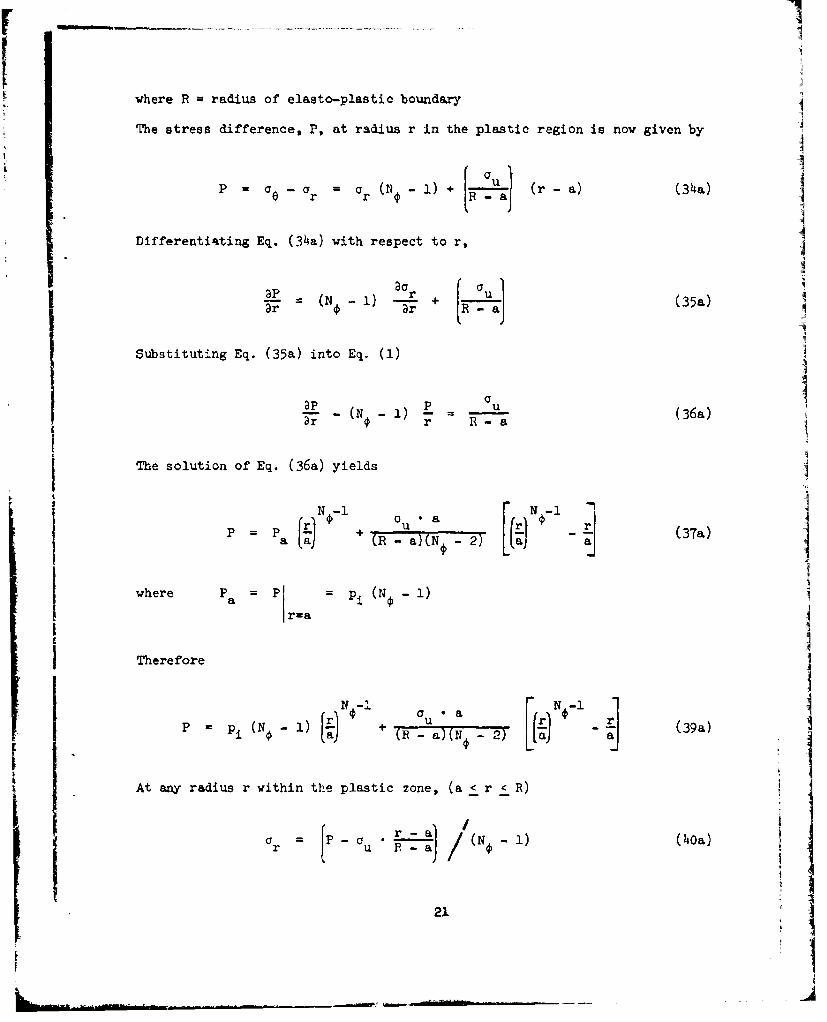
where R - radius of elasto-plastic boundary
The stress difference, P, at radius r in the plastic region is now given by ]
P = -a = a a (N - i) (r -a) (34a)0 r r 0
Differentiating Eq. (34a) with respect to r,
(aa_p (N 1) r + u (35a)- 0 Dr -R(al
Substituting Eq. (35a) into Eq. (i)
ap P p-(N 1) 7 T (36a)
The solution of Eq. (36a) yields
P P + 'u a - (37a)'a (La) R- a(N0 2)
where P Pr = P(N o -i)
r=a
Therefore
N au aFrN rlP= (No - i) + (B - a)(N 2) L - (39a)
At any radius r within the plastic zone, (a < r < R) i
a u ( -1) (0a)I
21

= 0 r •N¢ + u (33a)
Substitution of Eq. (39a) into Eq. (32) yields
N -1+ S (N +) = A r + B r (42a)
Dr
(N¢ 1 )2 pT•a
where A = N + ()-
C u '(N -i) I(43a)a N 1and = (R - )2 NT7
Solution of Eq. (142a) is of the form
N +2N¢+I ( 2A B r
Sr 2 r + N + 2 + C (44a)
where C is the constant of integration.
At r =R, S SRI
N +2
Therefore S = N +2 + C
Eliminating C from the above equation, Eq. (44a) can be rewritten as
• + A 2N 2N + B rN+2 - +21
2NRrN + I2R
+ S+R (51a)
22

I
At the elasto-plastic boundary (r=R)
2N (P + T) (N 1) (47)PR =N +-- 1-
According to Eq. (39a)
R (N -i) + a a(N¢ )[ - (45a)
Equating Eqs. (47) and (45a)
There is no closed solution of Eq. ((8a) for R/a. Eq. (48a) has to be solved for
R/a only by successive approximation.
2 (po + T)(N¢ 1 )At r R, S = = - (N +-) (47)
R (N T+ 1
Substituting this value of SR into Eq. (51a) and simplifying
N+ A 2N - 2N + B -N+2 N+21Sr = - [€ R +N+2 -
2 (p + T)(N -1) N.+1+ 0.(52a)
where A, B, and B are given by Eqs. (43a) and (48a). Eq. (52a) gives the value
of S at any radius r in the medium. The circumferential strain E0 can then be
calculated using Eq. (53).
23

In the elastic region (r > R) the stresses and strains are given by
Eqs. (19), (20), (5), (6) and (h6).
Data:
Unlined Tunnel: a = 8'
Po = 2000 psi
-6E - 6xl0 psi
= 1/3
Ou = 1200 psi
N =4
P = 0
Required: ?
Solution:
T 1200 40 psi (41)
3 21oo R 400 1 24ooWa - 2 - 2 = X- (48a)1 a 15
RtSolving R- 1.75 or R 1.75 x 8 = 14'
a
Note: If c is constant over the plastic region
a (2 x 40)1/Z = (5x 400 (48)
• R-- =1.34a
24

_ _ _ 2 _0 _400
(43a)
B0 - 020 • _ - 24ooa - 0.75 • a
At r- a
5 24o00 81 - 4 -A
S a 3 • R8
28400 x 5 (52a)5
Substitieing -- =1.75
II+ 28800 x 1.755
= 32200 psi
1 + (1 -) p
IS Jra
Note: If a is constant over the plastic zone
S =a 400 x .-g [3 +5 x 1.341 = 8300 psi (52) 1
and Ee = * (S+ ( - -pi) = 1.4 x Io25I
25 1

Case 3. Input Zarameters are the same as for Case 1 except that cohesion is
assumed to be lost in the entire plastic region, i.e..
Ou 0
The assumption of a complete loss of cohesion in the plastic region results
in the following modified equations:
Coulomb-Navier failure criteriu,..
oN= r (33b)
Stress difference P a r (N - 1) (34b)
P Pa " 4' (3m")
where P PI pi -±J-1
r=a
At any radius r within the plastic region
r P(N -1) (40b)
Ge = Or •N1 (33b I2
At r R, PP N + I o (N -1) (47b)
pi (N - )( (45b)
Thus R 48b)
26
ILI

Eq. (52) is now simplified as
s p + 1 N¢ [2N. (N -1) + (N¢ + 1)
Eq. (52b) can now be used to determine the tangential strain c6 at radius r.
In the elastic region, r > R, the stresses and strains are determined using
Eqs. (19), (20), (5) and (6) noting that aR = 2 p0/(N + 1).
Case 4. Input parameters are the same as Case 1 except that the quantities E
and p have Oifferent values in the elastic and plastic regions.
Let
E, E' - Young's modulus in the elastic and plastic regions
P, i. = Poisson's ratio in the elastic and plastic regions
k -E/E'
The tangential strain at the elasto-plastic boundary (r=R) must have the same
value in both the elastic and plastic regions. Since the values of the Young's
modulus are different in the two regions, there will be a discontinuity in the
tangential stress at r = R.
Let oR be the radial stress at the elasto-plastic boundary (r=R)
The circumferential strain at r = R due to stresses in the elastic
zone is
1 N +eR V u -
27

r?
The corresponding value at r R due to stresses in the elastic region
is
C - PO a PCOR E -R
Equating these two expre3sions for e
R k (N - ) + (i (46)
According to Eq. (h0) cR is also given by RJ
oR =(pi + T) (R - T (hOc)
Equating Eqs. (46c) and (40c) and solving for R/a:
R 2Po - 4 u
= k ) + + Tj1/N- ( 4 8c)
a Lk (N + (l +TJ (P
Eq. (48c) thus gives the radius of the elasto-plastic boundary.
For r - R (elastic zone)
r Po - (po a ) (19)
ce = + (Po-ar) (20)
1Ie (or pce) (6)
S(a - ir 2 (5)
28

For a < r < R (plastic zone)
= ( +T) T (40)ar --(i IT a]
=N • + a (33)
The circumferential strain Ee in the plastic region can be obtained from S which
is given by Eq. (52):
S N1) = i) + (N + 1) (52)pl + T,[!a 2No NO
E = 0 S + (l-')Or (53c)
Graphical Solution
The solution to Case 4 can also be obtained using the chart. In this case,
since the elastic and plastiv zones are assumed to have different material con-
stants, they will be treated as two different media arranged in a concentric
manner. For each medium (in this case for each zone) the appropriate chart will
have to be used.
Using the given data, the initial starting point is located in the chart of
one medium. Then the radial stress and the tangential strain at the boundary
between the two media are determined which are then used to locate the initial
starting point in the second2 medium. The same procedure can be repeated if there
are more than tio different media to deal with.
If the circumferertial strain and the radial stress are known at any
radius r in the medium, the procedure described above can be used directly to
29
estimate the free field pressure p0 or the modulus of the medium required to limit
the circumferential strain at the tunnel wall to a tolerable value under a given
value of p0 But very often the data may be insufficient to locate the initial
point in the chart for a graphical analysis, as for example, when it is required
to estimate the circumferential strain at r = a in Case 4 for a given value of po.
Under these conditions, it becomes necessary to use a successive approximation
procedure. For the example cited, an initial value of circumferential strain at
r = a is assumed and the graphical analysis is carried outward from the innermost
radius a and the value of p is estimated. If this value agrees with the value
given in the problem, the estimate of the circumferential strain at r = a is I
correct. If not, a revised value of the circumferential strain is assumed and the
procedure is repeated until the assumed circumferential strain is consistent with
the given data.
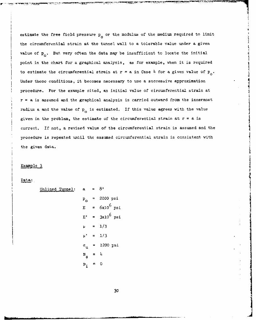
Example 3
Data:-
Unlined Tunnel: a = 8'
Po = 2000 psi
E = 6x10⁶ psi
E' = 3x10⁶ psi I= 1/3
p' = 1/3
a u = 1200 psi
No = 141
pi = 0
30
ma

Required: Ee r = ?r~a
Solution:
1200
- -- 400 psi (41)
k = E/E' 2
R =00 - 2Wo 0 + Woo 1 4oo] ( 4 8c)L-2 x3 2/ +/3 + 10 1/348¢
= 1.136 .
(Compare with the value 1.34 obtained for Example 2 with E = E' and au constant).
At r a
S 3 [r~ 8l= 4 - [3 + 5 (52)
7 [3+ 5 (1.136)8]
S : 2540 psi.
: - [2540 + 2/3 x 0] = 8.5 x 10 - 410
-4(Compare with the value 14xl0 " obtained for Ecample 2 with E E' and o u
constant).
31
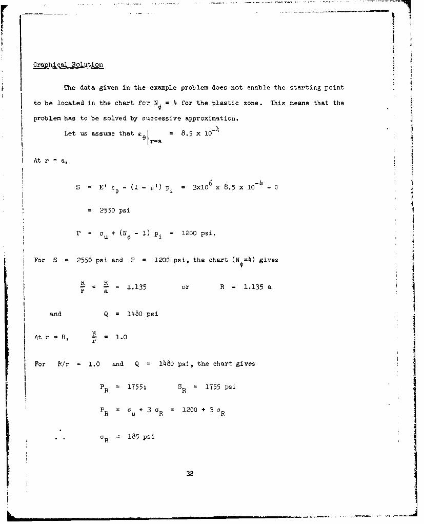
Graphical Solution
The data given in the example problem does not enable the starting point
to be located in the chart ffo:" No = 4 for the plastic zone. This means that the
problem has to be solved by successive approximation.
Let us assume that c. 8.5 x 0r~a
At r a,
S= E' - (1 - '. = 3x106 x 8.5 x 10- - 0
-2550 psi
P = U + (N 1) Pi = 1200 psi.
For S = 2550 psi and P = 1200 psi, the chart (N,=4) gives
R- - 1.135 or R = 1.135 ar a"
and Q = lh80 psi
Atr R, r = 1.0
For R/r = 1.0 and Q 1480 psi, the chart gives
PR 1 1755; S = 1755 psiIi RPR= u + 3R 1200 + 3 R
R 1 8 5 psi
32

SR O OR R
or OR = [ R + (R- ') ]
- 755 +- x 185I. - ~ ~3x107
= 626 x lo-6
Now in the elastic region
S R = E cOR (a R
= 6x1O6 x 626xi0- 6 x
= (3756 - 123) 10 = 3633 si
2po = SR + aR 4003 psi
Po = 2001.5 2000 psi (given)
This means that the initial assumed value of E.1 is correct.IIr=a
If the value of p obtained for aw assumed value of c.1 does not0 r=a1agree with the giver, value of po, the procedure has to be repeated with a second
trial value for £ . This repetitive procedure is continued until all theIIrIa
input data are satisfied.
33
33 1-- I

Case 5. In this case the tunnel is assumed to be initially surrounded with
circular zone of loosened materia. having elastic constants which are
different from those of the insitu material.
The case could represent a tunnel with a "destressed zone" from static
loading which is subseqaently loaded with another free-field stress such as a
dynamic loading over a large area.
Let a = radius of tunnel opening
R = radius of elasto-plastic boundary
R1 = radius of loosened zone
R = radius of elasto-plastic boundary in the loosened medium, if
any, when R > R
p 0 uniform free-field pressure
Pi= internal pressure at r = a
E = Young's modulus of intact medium
E = Young's modulus of loosened medium
= Poisson's ratio of intact medium.
ii' = Poisson's ratio of loosened medium.
= unconfined compressive strength of the medium (assumed to be
the same in both the intact and loosened zones)
1 + sin1 - sin 4
S= angle of shearing resistance of the mediun' (assumed to be
the same in both the intact and loosened zones)
In the analysis of tl.e t'esent problem, two distinct cases have to be
considered:
a) R < R b) R > R
34II

Case (a) R < RI
The elastic zone (r > R) in this case consists of two rings of material
with two different values of Young's modulus. Therefore the stresses and strains
in the elastic zone can be computed using the elastic solution obtained by
Sa in (1961),
For R r < R
a = oR + (po a- ) C1 (61)
CO = a +(po - aE) C2 (62)
where CI = [(1+ X2 ) (n 2- RI2/r2)] D (63)
X!1 / 2)]/
C, [(+ X,) (n 2 +a R 2/2 )/D (4
D =2 (a - 1)- n a 1) -(1 + x O (65)
X,=.~j- (66)
3--i (67)X2 = I+
n /R (68)
E(+'(69)
and R = r I
r=R
35

- I
For r > R,
i r = PO (po - aR) C3 (70)
= p + (po - aR) C3 (71)
l (n 2 + x) ( 2 Ewhere - 2 - (72)
L jr
The strains in the elastic zone can be obtained from the stresses as
follows:
For R< r < R1 r-E- ° (73)11
For< = E- (a0 - ii' Or) (73)E" rrE
_- =! (%r - 1') (74)
For r (> R -a ) (75)r r
Ce - 6 )- a r) (76)
However, in Eqs. (61), (62), (70) and (71), oR is still an unknown and
therefore has to be obtained before the stresses and strains can be determined in
the elastic region. This can be done by equating the circumferential strains at
r = R in both the elastic and plastic regions. Thus
l (a -i R ) = - (a p - p' R ) (77)
E 6 Rp R
36

r1
where a e 061 in the elastic region
r=R
aR p = 6 rR in the plastic region
Eq. (77) gives aene a 0 6RP !I
By Eq. (62) 0CRe R + (Po -R) C2 Ir -R
= aR + (Po OR) C (78)
2where C = (1 + x2 ) •2 n/D
In the plastic region
aRP = a R N 0 + au (79) j
Equating Eqs. (78) and (79), and simplifying J
OR N + uCj (80)
Eq. (80) can now be used in conjunction with Eqs. (61) through (76) to define
completely the stresses and strains in the elastic zone.
From Eq. (40) it is known that I
OR = (pi + T) a T)
Eqs. (80) and (81) can now be combined to yield
37I
37 1

II
a = -" + c + T pi + T) (82)
The value of R/a obtained from Eq. (82) should be less than Rl/a for the above1I
analysis to be valid. The analysis of the problem when R > H is considered
under Case (b).
The stresses in the plastic zone (a < r < R) are given by Eqs. (40) and
(33). The circumferential strains in the plastic zone can be determined from
Eq. (52) and
s = E' Ce" (1 - ) or (83)
i
Case (b) R > R1
When R > RI, the loosened zone may exist in any one of the following
three states, depending on the magnitude of the radial stress ael at r = Rl:
(i) Completely plastic
(ii) Partly plastic and partly elastic(iii) Completely elastic j
Therefore it is necessary to first determine the magnitude of cRl* The procedure
for determining aR1 is given below.
.ased on Eq. (48) it may be written that
l _ I2 p T
N+ 1 R1 +T (8) j_+TSimilarly from Eq. (52) it can be derived that
38
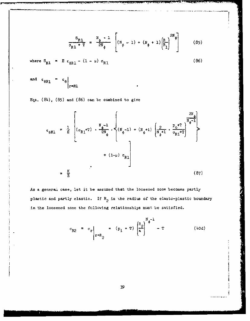
S R1 NN +1 +I 2N (85)I + T 2N
where SRl = E CR - (- ) OR1 (86)
and c R 1 = Ce1r R1
Eqs. (84), (85) and (86) can be combined to give
22I0i T ). ( N -I ) + C N + i ) 2_° T N -
£8R1 = E- ( R1+T) " N " + TJ
SK
(87)
As a genera case, let it be assumed that the loosened zone becomes partly
plastic and partly elastic. If R2 is The radius of the elasto-plastic boundaryin the loosened zone the following relationships must be satisfied.
N -i
(R2 = = (Pi+T) ] - T (40d)r=R2
39

a Rle = in the elastic loosened zone
r=R1
2 2RI + R2 21 2 2R2
a 0R1 2 2 R2R12 R2 2 (88)
1 2 1l - 2
eRl El ORle- i' o~) (5d)
Equating Eqs. (87) and (5d)
CeRl R = Ef K (89)
It can also be shown that
= ~ ~ 2 2 (01R1 " ]2 R2 2( N + i) oY + CTu 2 (9o))
R2RI -2 R21 2
Eqs. (89), (90) and (hOd) can now be solved to yield the values of the two
unknoWns a and RRI 2
If the loosened zone remains entirely elastic or entirely plastic,
Eqs. (hOd), (88) and (90) are not valid and cannot be used to determine 0
When the loosened zone is entirely elastic
U R1 (aI1 + a2 - Pi " 2 a2
0e21e = 2 2 (91)R -a
This value of cS~le can now be substituted into Eq. (89) to get the value of oRl.
Substitution of OR1 in Eq. (84) gives the value of R.
ho

When the loosened zone is entirely plastic, the values of R, a R and aR
can be obtained directly from the following equations-,
N-i-
[R 1
a=R (a R+ T) -T
The value of R obtained from the preceeiing equations should be greater
than R1 . If not, the procedure given under ce.se (a) has to be used.
Stresses and Strains
r R
ar = PO -p 0P - aCR) r](3
P+ (p -C R) (12 (94)
Cr a ~C -~ (95)
r (C (96)
where
C C =(2 p0 -Cr r N + 1u
~41

Rr r R
N ___
2 (p + T) R
= N + 1 T (97)
= N + a (98)e r T u
wh re S = E c0 - (I - ) r
a < r R1
Fully plastic
Cr (P i + T) a - T (100)
a r N + a (98)
SrV+1 (N - 1 ) 2 (p + T) 211 2N] + S IN +l (101)
Sr2 NF r ~' F.( 012N ra " Ri 1
where S E' ee - (i - ) 0r
S' E' -RI Ri - Rl
42

and eRl =C as obtained from Eq. (99).
Partly plastic and partly elastic
R 2 2r < R
aRl R 1 G R2 " 2 (aRi a R2 1 2102 2 2 2 2(102)RI - 2 (R1 -R R2)r
1 21 2C RI R12 - R2 R R22 (a RI - a R2) R 12 R 2 2
e =2 2 22 22 (10)
R R ( -R r1 2 1 2
Cr Ef r - '0 ) (io4)
Ce = 1 (ae - p'o) (105)
a< r <R 2
NO-1
Or = (pi + T) -T (100)
= • N, + a 98)
N +1 2NR 2N
he a T 2 L1i ) + (N. + I)[2 (106)
where S E' E (i - Or') r
43

pr -i - - .=i.---- -. w= .- * W wt h -rr' . w..r..crr..u-I -r-uP- rluP,,
Fully elastic
= A-B/r2 (107)
Ge = A + B/r2 (108)
where
2 2crR " Pi "a= 2(19)
1I 2
a2
RI Pi 1I
1
B = (ai-p)o)aB2 _2 (110)
(R - a)
1 _C r : l cr ( r o ) (104)
-c' ar) (105)El e rr(
The preceeding paragraphs thu-s give a complete and closed analytical
solution for Case 5. This problem can, however, be solved more readily by tne
graphical procedure using appropriate charts. The details of the procedure are
the same as explained at the end of Case 4.
Example 4
The input parameters for this example are the same as for Example 1 except
that the tunnel opening is surrounded by a loosened zone 8 feet thick having
the following properties:
44~

FL
E 2xO 6 psi
=1/3
=u 2000 psi
N = 24
Required: = ?
Solution: -J
This problem can be solved analytically using the relationships derived
for Case 5. But the procedure is long and time-consuming. Therefore the easier
graphical procedure is used in this example.
As has been explained earlier, the solution to this problem can only be
obtained by successive trials, the number of trials being dependent on how close
the first trial value is to the actual value. In the present case let us assume
Era 0.05
Then at r a O = 2000 psiuce = 0.05
E = 0 6
E =E' = XlO6 psi
' -- -- 1/3
1S x 0.05 - 0 105 psi (9)
P 2000 + 0 = 2000 psi (31)
For these values of S and P, read from Chart (N = 24)
145I

Q 8600 psiRI/I
-- = 1.725a
At r =R 1 = 2a (=16') R 0.863 A
Ri
R RFor Q - 8600 psi and - = . 0.863, read from the chartr R
(loosened medium) = 7700 psi
r=R1 1At < 1, the material is elastic at r = RI
2 Po -S 2 (Q -T)-S S i- = (Q--T) (19)
2 2 2r=IRI
-(8600 667) _ 7700 = h083 psi.
At r R in the loosened zone,
= + (1- ') r]
[7700 +-x 4083]I2x106 3 0
- 5211 x 10- 6
At r = R in the unloosened zone
46

W ,r T
S = Ee (- r (9)
- 6x106 x 5211 x 10- 6 x 4083
= 28544 psi
P = au + (N - 1) = 2000 + 3 x 4 083 (34)
= 14250 psi
For these values of S and P, the chart for N@ = 4 gives
Q = 16900 or Po = Q - T = 16900 - 667 16233 psi
This value is sufficiently close to the given value of p0 of 16400 psi. So the
assumed value of cel = 0.05 is very near the correct value and the calcula-
tions need not be repeate.
Case 6. Lined tunnel with a circular zone of loosened material.
A tunnel may be provided with a liner to limit the strains at the inner
surface of the tunnel within allowable limits. The linings may be of concrete
or steel or a combination of both. In this analysis the liner materials also will
be assumed to behave elasto-plastically. The analytical solution of the stresses
and strains in a tunnel system consisting of one or more sets of liners and a
loosened zone of material surrounding the liners, is very complex, lengthy and
cumbersome. However, the graphical solution, using the charts of the type
presented earlier, offers a relatively simple means rf solving the problem.
47

The analysis must proceed outward from an inner element or inward from an outer
element of the tunnel system. For each element of the system the chart with the
appropriate value of N has to be used. At least two quantitiessuch as the
circumferential strain or the radial stress, are required to locate the initial
starting point for the analysis of any one element. Once these quantities are
known, they can be used to estimate the values of the radial stress and circun-
ferential strain at the boundary with the next element, which are in turn used
to locate the starting point for the analysis of that next element. This process
can be repeated until the stresses and strains in the whole tunnel system are
known. The following example is worked out to illustrate the approach mentioned
above.
Example 5
The dimensions and rock properties assumed in this example (Fig. 8) are
the same as for Example 4 except that the tunnel opening is provided with a 12"
thick liner of concrete having the following properties:
E c = 4x10⁶ psi
= 1/3
C = 5000 psiu
Required: C0 L =
Sr=a
48!

Solution:
Let us consider the concrete liner first. Let us assue, as a first
-Itrial value,
Ce - 0.03
r=7'
It is known that at r 7'
=0r
s 4 x 106 x 0.03 - 0 1 .2 x 105 psi (9)
i 5000 + 0 5000 psi (34)
For these values of S and P, read from chart [N (concrete) = 4]
Q =16500 psi
R- = 1.57, thus R = 11'7
At r =8' R 1 1r = -g= 1.37'5
For Q = 16500 psi and = 1.375, readr
S = 64000 psi
P = 7600 psi = 5000 + 3 C (34)
Therefore at r = 8' Ir = 867 psi
49
I

1I
= . . (64ooo + 2/3 x 8671 (53)4x10
- 16147 x 106
Let us now consider the loosenei zone.
At r =8'
= 16147 x 10- and
= 867 psi
S = 2 x 106 x 16147 x 10- 6 2/3 x 867 (9)
=317?_0 psi
F = 2000 + 3 x 867 = 4600 psi (34)
For these values of S and P, read from the N = 4 chart for the loosened zone,
Q - 9250 psi
= 1.34 R - 10.72'
At r = 16' .67 10.7216
For Q = 9250 psi and R = 0.6'r, readr
S = 5000 psi
As 0.67 < 1, the value of P is not valid, bul car, be caicuated usingr
the relation
S= PO - wherePo = Q-T
50

Thus at r = 16'
a (Q-T) S (9250 667) 50oO
I1
= 6083 psi
£e = + 2 x 6o83] (53)0 2:707 L =
i0.6
= 4528 x
Let us now consider the intact (non loosened) medium.
At r 16'
6= 528 x 10-
0r = 6033 psi
" 21
s1= 6 x l0 6 x 4528 x 10-6 2 x 6083 (9)
= 23113 psi
P = 2000 + 3 x 6083 (34)I
= 20250 psi
For these values of S and P, IQ = 18200 psi
and PC = T 18200 -667 = 17533 psi
I
53.

But the value of p0 specified in the problem is 16400 psi. This means that the
assumed value of El r=71 = 0.03 is slightly on the high side.
So let us now assumn. that at r = 7'
Ce = 0.028
A similar analysis gives the following values:
At r = V' In concrete
S = 1.12 x l05 psi P = 5000 psi
At r = 8' In concrete
S = 5.95 x 10⁴ P = 7500 psi
= 833 ps-r :.
= 15014 x l0 - 6
In loosened zone
S = 29472 psi P = 4500 psi
At r = 16' In loosened zone
S 4.7 x 10 psi
a = 5883 psir
E = 4311 x 10- 6
52

In intact zone
S = 21944 psi P - 19650 psi
P0 = 16433 (- 16400) psi
Thus the assumed value of c (at r 7') 0.028 is very near the actual
value.
Note: For relatively thin steel liners, the analysis is slightly simplified
because the radial pressure exerted by the thin steel liner against the medium
next to it is given by
h ha E E or°ra a a 6 y
whichever is less. In the above equation
ara o radial pressure exerted by steel against the
adjacent medium
h = thickness of steel linings
O = yield stress of steel lining
a = radius to outside of steel lining
E = Young's modulus of steel lining
ce = circumferential strain of the steel liner
Case 7. Tunnel provided with back packing: Loosened zone present.
This case is very similar to Case 5, the only difference being that the
radial pressure pl at r = a is 0 0. The back packing material usually has a
53

very low yield value and serves to exert an equal all around pressure on the
inner surface of the tunnel over a considerable range of strain. The analysis
for the present case is illustrated by the following example problem and is very
similar to that of Example 4.
Example 6
The input parameters are the same as those of Example 4 except that the
radial pressure due to back packing is 150 psi (Pi = 150 psi).
Required: =?
r=-a
Solution:
Assume at r =a8', 0 = 0.04
Then at r = 8'
- ? x 106 x .04 - x 150 = 79900 psi (9)3
P = 2000 + 3 x 150 = 2450 psi (34)
For these values of S and P read from chart (11 =4)
R9000 p3i = 1.64'
R =13.12'
At r 16'
R 13.12 0.82 < ir 160..2o -1
54

For Q * 9000 psi, 0.82 S 7250 psir4
S
:i
- (9000 - 667) - 3625 1
a 4708 psi
.41 7 [250 .9x To8
" 5195 x 10-6
Now for the intact material ot r = 16'
4+708 psirI
C ... =5195 x 10
S1 6 x 5195 y - x 47O8 (9)
280o40 psi IP = 2000 + 3 x 4708 = 16124 psi (34)
For these values of S and P 1I18000 psi
Po - T = 17333 psi (in comparison vith the actual value of I164oo psi)
551

Therefore the assumed value of c,9 at r = a = 8' has to be revised. So let us now
assume at r =81 = 0.038.
A similar analysis leads to a value of p 0 =16633 psi. So '~y a slight
extrapolation it can be found that for p0 = 16400O psi,
Cel 0.03T3 or 3./"P
56

Chapter 3
Conclusions
General
The analysis presented in the previous chapter yields a means whereby
stresses and strains can be determined around a circular tunnel in a Coulomb-
Navier material which increases in volume at f2ilure. This analysis may be used
to design liners if the insitu rock properties are known. The results of the
analysis are dependent on the rock properties assumed; therefore, recommenda- Itions are given in this chapter on the selection of the approriate rock mass
properties to use in this analysis. The effects of a non-uniform system of
free-field stresses are also discussed.
I
Shear Strength Properties
The values of a and N to be used in the analysis are related to the
rroperties of the jointed rock mass surrounding the opening. N. is given by
1 + sin where the appropriate angle of frictional resistance should be taken1 - sin 4
as the angle of frictional resistance along the joints or discontinuities not
the angle of internal friction derived from triaxial tests on intact samples of
rock. The value of the uncoifined compressive strength of the rock mass, o , is
a function of the ratio of tunnel diameter to joint spacing as shown in Fig. 9.
The larger the ratio of tunnel diameter to joint spacing., D/S, the smaller the
value of a appropriate for design. If D/S is very small the value of a can
approach the unconfined strength, qu, of intact sAmples of the rock surrounding
the tunnel. Similarly if D/S is Very large au approaches zero and the shear I57,I

strength of the rock mass approaches the shear strength along the joints. Fig.
10 gives a straight line relationship between the ratio of au/qu and the ratio
of D/S which can be used to select a value of au for design if qu and D/S are
known. This relationship is based on field experience in locations where dis-
placement and strain measurements have been made.
Elastic Properties
The method of analysis presented in Chapter 2 is also quite dependent on
the "effective" modulus of elasticity, E, selected for the rock mass. A method
for selecting the deformation modulus of a rock mass has been given by Deere,
Hendron, Patton and Cording (1967). By this method the rock quality of the rock
mass must first be assessed quantitatively in terms of the Rock Quality Designa-
tion (RQD) or the Velocity Ratio as described by Deere et al (1967). After the
rock quality has been determined Fig. 11 should be entered on the abscissa using
the RQD value or the square of the velocity ratio and the reduction factor
E IE should be determined from the dotted line shown in Fig. 11. Ther seis
reduction factor is the ratio of the deformation modulus of the rock mass Er
to the dynamic value of Young's modulus Eseis calculated from P wave velocities
measured in seismic surveys. The deformation modulus of the jointed rock mass
can then be taken as the product of the reduction factor and E seis.
This analysis is not very sensitive to the value of Poisson's ratio
selected, which is fortunate because there is little known albout the selection
ot a Poizszon'ls ratio for an insitu rock mass. It is recommended that a Poisson's
. 0.3 be i,-ed.
58

Dilatancy
tI
Dilatancy of the rock mass at failure is accounted for in the elasto-
plastic analysis by the normality condition expressed by Eq. 24. Experimental
evidence however suggests that the increases in volume resulting from the
normality condition are too large compared to the behavior of real rocks. Thus
the radial displacements or tangential strains computed by this theory are
a conservative upper bound. On the other hand the charts developed by Newmark
(1969) are based upon no volume change due to the plastic strains at failure
and give radial displacements and tangential strains which are too small andL
should be taken as a lower bound. The charts given in Figs. 3-7 would be
identical to Newmark's charts if the lines of constant Q in the elastic region
are extended as straight lines into the plastic region. The proper amount of Idilatancy to include in calculating strains and displacements is somewhere
between that given by Newmark (1969) and the analysis given herein.I
Non-uniform Stress Conditions
For real design problems the free-field principal stresses in a plane
perpendicular to the tunnel axis may be a1 and 03 where cI is the major principal
free-field stress and a3 is the minor free-field principal stress. The solution
for this problem cannot be obtained in closed form as was done in this paper
for the case of a, = a3 = Po. Reyes (1966) has solved several problems for
unlined openings in a medium with Coulomb-Navier failure properties and
dilatancy, as described in this report, for non-uniform free-field stress con-
ditions. A comparison of the uniform, free-field stress solution presented
herein with the solutions presented by Reyes has shown that the maximum diametral
59

strain 6 r/r (max) across the tunnel in the non-uniform stress field (free-field
rIstresses = c and a3) is closely approximated by the solution given, herein if
PO is assumed to be equal to the major principal free-field stress, a1. The
distortion of the tunnel from a circular shape can also be approximated within
20 % if the minimum diametrdl strain 6 r/r (min) is taken as
6r a 3 6rr (rain) a 1 r (max)
Since the ratio of a3/1 for protective structures problems may range from
about 1/3 to 2/3 the minimum diametral strain of the tunnel may be approximated
for preliminary design purposes as being about 1/3 to 2/3 the maximum diametral
strain across the tunnel. Reyes solution has also shown that the maximum
diametral strain of the tunnel occurs across a diameter parallel to the
direction of a and the minimum diametral strain occurs across a diameter
parallel to a3*
For preliminary design purposes it is felt that the approximations
given in this section for estimating tunnel distortions for the non-uniform
stress field are at least as accurate as the initial assumption of the ratio
of C3/a1 appropriate for design problems in protective structures. If more
accurate estimates are desired, then time consuming and expensive finite
element calculations similar to those used by Reyes (1966) must be performed.
60

Deere, D. U., Hendron, A. J., Jr., Patton, F. D., and Cording, E. J., 1967,
4
"Design of Surface and Near-Surface Construction in Rock," Proceedings
of the Eighth Symposium on Rock Mechanics, Charles Fairhurst, Ed.,The Amer. Inst. of Mining, Metal. and Petroleum Engrs., Inc., New York,pp. 237-302.
Drucker, D. C., and Prager, W., 1953, "Limit Analysis of Two and Three-Dimensional Soil Mechanics Problems," J. Appl. Mech. and Phys. Sol.,Vol, 1, No. 4, pp. 21T-226.
Jaeger, J. C., 1956, "Elasticity, Fracture and Flaw," 208 pp., Methuen 4 Co..Lt d., Lon don.
JDeger, J. C., and Cook, . G. w., 1969, "Fundamentals of Rock Mechanics,"
513 pp., Methuen & Co. Ltd., London.
Newmark, N. m., 1969, "Design of Rock Silo and Rock Cavity Linings," TechnicalReport to Space and Missiles Systems Organization, Air Force Systems
Command, Norton Air Force Base on Contract No. FO 4701-69-C-0155.
Reyes, S. F., 1966, "Elastic-Plastic Analysis of Underground Openings By TheFinite Element Method", Ph.D. TheVis, University of Illinois, Dept. of
Civil Engineering.
Savn, G. N., 1961, "Stress Concentration Around Holes," Pergamon Press,
New York.
Sirieys, P. M., 1964, "Champs de Contraintes Autour des Tunnels Circulaires enElastoplastrcite," Rock Mechanics and Engineering Geology, Vol. II,5o. 1, pp. 68-75.
Terzarh, K., 1919, "Die Erddruckerscheinungen in rtlich beanspruchtenSchRttunge und e Entstehung yon Tragksrpern," AsterreichiesheWochenschrifto fr rffentlchen Baudenst, Nos. 1 7-19, pp. 194-!99,
2o6-210, 218-223.
Terzagi, K., 1943, "Theoretical Soil Mechnics," 510 PP., John Wiley & Sons,New York.
Westergaard, H. M. 194o,"h, "Plastic state of Stress Around a Deep Well,"Journal of the Boston Society of Civil Engineers, Vol. XXVII, No. I,Nanuary 1940.
61

r
bi
rr
FIG. I (a)
Pi ELASTIC-
FIG. I (b)
/ 62FIG. I C IRCULAR.. TUNJNEL SIJRJFCTED.TO, AN I1SOTMArflI FRF -Fl fl STOW

Iz
k. ______________________________________________________________________
0z
crz
0
ac
C-LNM -
-LJ
C%1
63

copyNp
100,000 J., J;; A!ffkff9
I LVP KIM i fIs M ;k 11 r
IL I tT11
2
40
PO.0009 le"i r
-7. _ 4
:YIDR
41i'
CL 1 4 :',t,
-lei1000 -F?%.L 1 09 ..... ......
71.
t -41 T 'I""
14 in
,4 44t
:1:N;j1,0
foc'000 t 6 7 8 9 i0,00C 2 5 5 6 7 a 9 100.000 2 6
S E#9 - ( )a,
FIG 3 GRAPHICAL ILLUSTRATION OF RELATIONS AMONG P, S, AND Q FOR N 2
64

1,om,,-Iablo COPY'
N
too.000 IH9 1.o +JjVrj...-" u
vir,4 1)ior- I . .....t -L-rT11A
AI .L
tt!-.
f
00.000
9
+14 -A Nt
M
+
blu Ir t
1000
r
'414 4
i T
2
'001000 2 3 5 6 a 910,000 2 3 5 6 7 8 9000,000 2 3 4 5 6 1.000,OW
S= Eta - I - L i (r,
FIG. 4 GRAPHICAL ILLUSTRATION OF RELATIONS AMONG P, S, AND Q FOR Noz 3
65
A

N -4
10,00
-- ,SEE - (XIFIG. 5~~~~~~~~~~ GRPHCA ILUTAIOOFRLTOSANGPSND0ORN-
1 1 4nromcopyN

rA-------
itt 4
-A V
bT
It
4T
0(A I 4 5 6701,0 4 5 6 * J'
4- is,
Flu AL LLUSTRAION OF ELATIOsAMN P' NDQF Nj
jijL44j

tco
0~0
9 Jmm A Et t 04(t
Fl~~~~~~~~~~ lAILUTRAINO EAIOSAOGP , N O

(,oncrfAe Liner ,o s n d o
ti;, Destressed" Zone hisituRock Moss
FIG. 8 GEOMETRY OF PROBLEM ASSUMED IN EXAMPLE 5
69

- - - - - - -- - - - -
(1 aN 2:rOIT
(2
FiG9 LLSTRTIN F NCC~FNDSRN SAFNTOOF~~~~ TUNE DIMEE T1 NON T33N
YOu u2fDs

w
wz
z
z
cI Iz
U) co01M'~-(0Oz
-Uw a:
CL
-19-
311 I<
= . 0 M I U) -j
a- c 0 0
ll7 0LM L -- -

IiI10
! _ _
- Ieo4e
0 ILi, -
C F.o 0.4
6'V' ~
00 0.2 0.4 0. 0.8 1.0
2
Rock Quality, (VF/VL), ROD
DYNAMIC TEST DATA0 CEDAR CITY TONALITE
0 QUARTZ MONZONITE -CLIMAX STOCK
A BUCKBOARO MESA BASALT
FIG. II RELATION BETWEEN ROCK QUALITY AND REDUCONFACTOR
J.