0dwhuldo (6, iru&khplfdo6flhqfh 7klv - the … redox cycling and luminescence on multiscale...
TRANSCRIPT
Self-Induced Redox Cycling and Luminescence on Multiscale Bipolar Electrodes S1
Supplemental Information for
Self-Induced Redox Cycling Coupled Luminescence on Nanopore Recessed Disk-Multiscale
Bipolar Electrodes
Chaoxiong Ma1, Lawrence P. Zaino III1, and Paul W. Bohn1,2*
1Department of Chemistry and Biochemistry, University of Notre Dame, Notre Dame, IN 46556
2Department of Chemical and Biomolecular Engineering, University of Notre Dame, Notre
Dame, IN 46556
1. Fabrication of Bipolar-Recessed Disk Electrode (BRDE) Nanoarrays
Using procedures similar to those developed previously to fabricate recessed ring-disk
electrode arrays,1 BRDE arrays were fabricated on glass slides using layer-by-layer deposition,
nanosphere lithography, and a reactive ion etching (RIE) process (Fig. S1)
a) After cleaning with piranha solution, the glass slides were patterned by photolithography
using AZ5214E photoresist (PR) to define an electrode area of 200 µm x 200 µm (WE in
layout). A 200-nm thick Au film, using 5 nm Cr as an adhesion layer, was deposited by
thermal evaporation. The undeveloped photoresist was then removed by rinsing with acetone.
b) A 100 nm silicon nitride (SiNx) layer was then deposited on the Au electrode by plasma-
enhanced chemical vapor deposition.
c) The substrates were then coated with a compact monolayer of polystyrene (PS) spheres to
template the electrode array using a nanosphere lithography approach reported previously.2
Briefly, 5.0 wt% PS solution (in 1:1 methanol/water) was spread onto the surface of water in
a petri dish, producing a monolayer of PS spheres at the air-water interface. This PS
Electronic Supplementary Material (ESI) for Chemical Science.This journal is © The Royal Society of Chemistry 2015
Self-Induced Redox Cycling and Luminescence on Multiscale Bipolar Electrodes S2
monolayer was transferred to the electrode surface by partially dipping the wetted substrate
into the water. The PS-decorated substrate was then exposed to an O2 plasma (50 W) for 8
min to reduce the size of the spheres to ca. 700 nm.
d) Using an Al mask, the top Au (50 nm) electrodes (Planar and CE/QRE in layout) were
deposited to overlap the bottom electrode covered by SiNx film and PS spheres.
e) The PS spheres were removed by ultrasonicating the substrates in CHCl3 for 5 min, followed
by a 10 min exposure to a strong (1500 W) O2 plasma was used to remove the PS spheres.
f) An additional 200 nm of SiNx was deposited over the entire substrate after removal of the PS.
g) Photolithography was then used to develop the areas of interest to be selectively exposed to
the following etching process. The first area (OA) of dimensions 100 µm x 100 µm was
opened over the nanopore BRDE array, and a second area (OP) with size varying from 100
µm x 100 µm to 1 mm x 5 mm was opened over the remote portion of the bipolar electrode.
The distance between OA and OP was either 0.5 mm or 6 mm. The contact pads of the
electrodes were defined by using PR as an etch mask (not shown in Fig S1).
h) The SiNx layer on the OA and OP contact pads was removed by reactive ion etching using a
mixture of CF4 (45 sccm) and O2 (5 sccm) at 50 mTorr and 50 W rf power for 3 min. Acetone
cleaning followed by exposure to a high power O2 plasma (1500 W, 10 min) were used to
remove the PR after etching.

Self-Induced Redox Cycling and Luminescence on Multiscale Bipolar Electrodes S3
Figure S1. Schematic illustration of the fabrication procedure and the layout for the BRDE
array. The colors are used to represent different layers: grey (glass), yellow (Au), blue
(SiNx), purple (polystyrene sphere), and brown (photoresist). OA and OP are the open
areas defined in the main text.
Self-Induced Redox Cycling and Luminescence on Multiscale Bipolar Electrodes S4
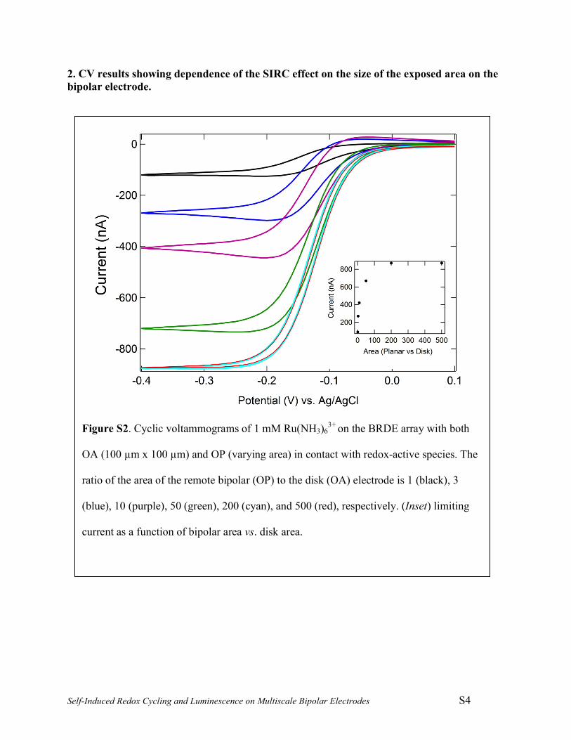
2. CV results showing dependence of the SIRC effect on the size of the exposed area on the bipolar electrode.
Figure S2. Cyclic voltammograms of 1 mM Ru(NH3)63+
on the BRDE array with both
OA (100 µm x 100 µm) and OP (varying area) in contact with redox-active species. The
ratio of the area of the remote bipolar (OP) to the disk (OA) electrode is 1 (black), 3
(blue), 10 (purple), 50 (green), 200 (cyan), and 500 (red), respectively. (Inset) limiting
current as a function of bipolar area vs. disk area.

Self-Induced Redox Cycling and Luminescence on Multiscale Bipolar Electrodes S5
3. Optical image of ECL measurement showing the change of the ECL intensities on the disk (OA) and bipolar electrode (OP) with concentration of TPA
Figure S3. Optical image of ECL measurements on the BRDE array in 5 mM Ru(bpy)32+
and 20 mM (a), 50 mM (b), and 100 mM (c) TPA.
(a)
(b)
(c)
OA OP

Self-Induced Redox Cycling and Luminescence on Multiscale Bipolar Electrodes S6
4. ECL measurements on microdisk electrode showing the change of ECL intensities with the concentration of TPA
Figure S4. (a) (Top) Potential modulated ECL on a microdisk electrode in 5 mM
Ru(bpy)32+ and 0 mM (black), 1 mM (blue), 5 mM (red), 20 mM (green), 50 mM (cyan)
and 100 mM (purple) TPA; (Bottom) Applied potential vs. QRE as a function of time.
(b) The maximum ECL intensity as a function of TPA concentration
Self-Induced Redox Cycling and Luminescence on Multiscale Bipolar Electrodes S7
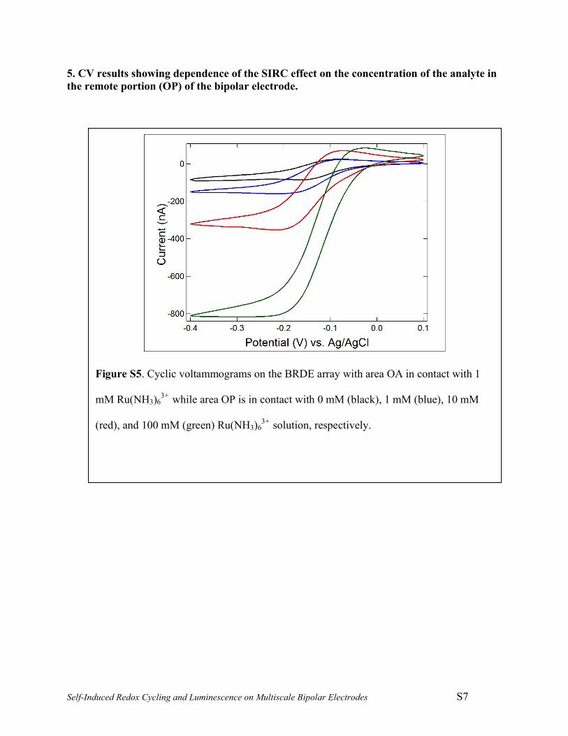
5. CV results showing dependence of the SIRC effect on the concentration of the analyte in the remote portion (OP) of the bipolar electrode.
Figure S5. Cyclic voltammograms on the BRDE array with area OA in contact with 1
mM Ru(NH3)63+
while area OP is in contact with 0 mM (black), 1 mM (blue), 10 mM
(red), and 100 mM (green) Ru(NH3)63+
solution, respectively.

Self-Induced Redox Cycling and Luminescence on Multiscale Bipolar Electrodes S8
References (1) Ma, C.; Contento, N. M.; Gibson, L. R.; Bohn, P. W. ACS Nano 2013, 7, 5483. (2) Li, H.; Wu, N. Nanotechnology 2008, 19, 275301/1.