09028 - coatings failures in plants and …rozup.ir/download/194337/09028.pdf · by the choice of...
TRANSCRIPT
2009
Copyright ©2009 by NACE International. Requests for permission to publish this manuscript in any form, in part or in whole must be in writing to NACE International, Copyright Division, 1440 South creek Drive, Houston, Texas 777084. The material presented and the views expressed in this paper are solely those of the author(s) and are not necessarily endorsed by the Association. Printed in the U.S.A.
COATINGS FAILURES IN PLANTS AND INDUSTRIAL ENVIRONMENTS
Oluwatoyin Ashiru and Mohammed Al-Sonidah
Saudi Basic Industries Corporation (SABIC)
SABIC Technology Center
P.O. Box 11669
Al-Jubail 31961
Saudi Arabia
ABSTRACT
Protective paintwork is an important item in construction and maintenance operations in
industrial plants. A properly selected and applied coating system will reduce the rate of corrosion and
therefore the costs associated with corrosion. In industrial plants, coating failures may occur if incorrect
coating material is used or the materials are poorly applied. Coating failures may appear during
application, during drying/curing, or after a certain period of service life. There are many reasons why
coatings fail and it requires a lot of experience to find the exact cause. In this paper, case studies of
coating failures that were experienced in industrial plants will be presented showing how the varied
causes of failure were established as well as the remedial actions that were undertaken. The goal is to
demonstrate how to specify the most cost effective coating systems and application procedure for
various requirements in plants.
Keywords: Protective paintwork, coating selection, corrosion under insulation, coating failures, coating
deterioration
INTRODUCTION
This paper describes investigations that were conducted on equipment in various industrial plants
to determine the causes of coating failures. Remedial measures were then proposed. The items that
were included in the corrosion survey include piping, storage tanks, equipment, supports, and insulation
systems. The items in the plants had undergone different levels of corrosion degradation varying from
moderate to severe.
Due to the environmental conditions under which these plants operate, atmospheric corrosion has
proven to be a major problem. During the turnaround maintenance of the plants, severe corrosion was
noticed in different areas. The situation threatened structural integrity of some of the structures in the
plants and in some cases presented safety concerns. Our team visited the plants over several months to
1
Paper No.
09028

assess the extent of corrosion of the plant structures. During this period, extensive survey and laboratory
analyses of corrosion products were carried out to establish the nature of the rust deposits.
Extensive visual inspection was conducted to establish the extent and causes of corrosion and
other forms of material degradation. Investigation of corrosion processes in the plants involved the
inspection of storage tanks, piping, supports, flanges, nozzles, joints, insulation systems, and other
auxiliary items. All the inspected structures had experienced different levels of corrosion varying from
minor to severe. Most of the inspection activities consisted of detailed visual examination of the
affected structures and photographing areas of interest. The general nature of the corrosion damage that
was seen in the plants and the corresponding recommended remedial measures are categorized in this
paper under three broad sub-headings as described below.
DISCUSSION
Case Study #1
Although a number of tanks in a plant had been recently painted, cracked coating material and
rusting were evident (Figure 1). None of the tanks suffered any significant paint failure or corrosion
problems. No serious occurrences of coating delamination (flaking) were observed. During
conversations with plant personnel, it became apparent that the storage tanks and associated piping had
all experienced external corrosion in the past. This was confirmed by a closer examination of the
surfaces of some of the structures - hairline cracks were observed in the topcoats.
Much of the piping showed coating deterioration which allowed some corrosion (Figure 2). The
exterior paint systems had completely failed in some localized areas. The failures were largely caused
by the choice of inappropriate coating materials and improper coating application procedures. Localized
flaking of paint films was observed on most flanges and auxiliary piping of varying diameters (Figure
2). Heavy rusting was noted on the exposed substrate after the coatings were removed. The rust
consisted of brownish deposits - an indication of prolonged corrosion. Subsequently, the rust flakes
were removed from the steel surface by knife for laboratory analysis. The rust deposit was examined by
X-ray diffraction (XRD). The results revealed a mixture of γ-FeOOH, α-FeOOH, and some α-Fe2O3.
But the predominant species in the deposit was α-FeOOH. The relative abundance of α-FeOOH
suggested that the corrosion process was at an advanced stage, that is, the corrosion product was fairly
old.
After removal of the coating from what looked to be a well coated area with intact coating, the
texture of the steel substrate was smooth with no evidence of there ever having been a blast profile. This
was a clear indication of poor surface preparation prior to coating application. Corrosion occurred
primarily as undercutting. While the areas with undercutting were minimal compared with the entire
coated surface, the remaining adjacent areas could still be susceptible to the same condition and failure
mechanism. The service life of coatings is largely dependent on the condition of the substrate at the
time of paint application. Thus, it was necessary that the entire existing coating system be removed
from the steel substrate in order to achieve the full benefits of the new coating system.
Another corrosion problem affecting painted surfaces was localized corrosion in the weld heat
affected zones of the coated items. This is illustrated variously in Figure 3. It is well known that
welding can modify the corrosion behavior of the metal. Weld metal has a cast structure as it solidifies.
There is a change in the microstructure of the metal as one moves from rolled plate into the weld metal
and then back into plate or pipe. Alloying elements may not be uniformly distributed across the weld
2

area. Susceptibility to corrosion may be enhanced. Premature corrosion of welded steel can also be due
to lack of surface grinding resulting in poor paint adhesion. Welded joints should be ground smooth or
flush to enable good coating adhesion and performance.
A primer is the first coat of a system and its principal functions are to provide adhesion and good
protection to the substrate. Where primer is not properly applied, premature coating failure can occur.
Generally, coatings should only be applied to fully and correctly prepared surfaces. Paint films are
known to be permeable to water and oxygen and this can affect their properties. Faster paint breakdown
may occur due to high temperatures, moisture-laden atmosphere and high ultra-violet solar radiation.
Fading and discoloration, chalking and cracking followed by peeling and general embrittlement can take
place rapidly.
The failure of the coating on some of the structures in the plants was generally due to a
combination of factors. It is essential that coating repair be executed in a timely fashion. It appeared
that had not been the case in many areas of the plants. It is our general practice to repaint steel surfaces
when 0.2-0.5% of the surface area shows evidence of rust. Delay in repainting may be a false economy,
since if rusting is extensive it may be necessary to clean down to bare metal before paint can be applied.
Considering the extent of coating deterioration, cleaning down to bare metal would be necessary
before the application of new coating. A continuous intact film of water-resistant coating forms an
effective barrier to ionic transport. The electrochemical corrosion circuit is completed by the migration
of ions in the electrolyte. Cations migrate to cathodic areas. Anions migrate to active anodic areas. The
coating protects by providing an electrical resistance to ion migration. Underfilm corrosion can only
occur if a path of electrolyte connecting anode and cathode can be established. Local adhesion failure
occurs most easily where broken scale or rust, or deposits of salts have impeded wetting of the metal
substrate by the film-forming constituents of the paint. Small traces of certain corrosion stimulants,
especially soluble chlorides and sulfates can maintain a continuing corrosion process under a paint film.
This is because chloride ion in particular, accelerates the initial dissolution of iron to yield ferrous ions
in solution. The ferrous ions eventually go to insoluble hydroxide and oxides, but the chloride ions
remain soluble, providing a good electrolyte.
Several of the structures in the plants were found to be undergoing active corrosion in some
areas. The corrosion damage is due to factors such as:
Coating deterioration caused by the use of inappropriate coating materials and improper coating
application.
Use of inappropriate insulation material and poor installation of insulation systems.
Contact between dissimilar metals (galvanic corrosion).
The corrosion damage in the plants had escalated to the point where the plant production processes
could have been adversely affected in the near future. Thus, immediate steps were taken to re-coat, re-
insulate, replace, or refurbish damaged structures as indicated below.
Our recommendations on the most effective repair and remedial measures were as follows:
Re-paint the plants: Most of the external corrosion problems were rectified by proper coating
selection, application, and regular maintenance. The facilities that required re-painting were all the
3

external part of the plants consisting of tanks, auxiliary pipes, flanges, and braces/stanchions.
Suggestions on coating choice and application procedures are indicated below:
Surface Preparation:
In order to execute the painting work properly, it was recommended that areas
not involved in the preparation, application of coating, and drying stages be
temporarily shut down from the processing operations. Items that would be
excluded from the blasting and painting operations were to be fully covered or
otherwise protected.
Any oil, grease and similar contaminants that were present on substrates were to
be removed by suitable degreasing/emulsifying agents, followed by high
pressure fresh water washing to remove water soluble contaminants. Surfaces
would be allowed to dry completely. Abrasive blasting to a minimum
cleanliness level of Sa 2 ½ (near-white metal) was required.
Coating System:
We proposed a three-coat system which would consist of:
(a.) Primer: A two component polyamide cured epoxy containing zinc phosphate as
corrosion inhibiting pigment applied at a thickness of 50 microns DFT.
(b.) Intermediate Coat: A high-build, high solids polyamide cured epoxy at a thickness of
100 microns DFT.
(c.) Topcoat: A two component polyurethane coating applied at a thickness of 50 microns
DFT.
Case Study #2
The existing thermal insulation on piping systems in the plants (Figure 4) was thoroughly examined
by visual inspection. Several locations were identified where corrosion under insulation (CUI) had
occurred. The underlying coating had failed. CUI is caused by the penetration of corrosive agents
through the insulation material to the metal surface. An example of CUI damage can be seen under the
brownish stained region that is depicted in the lower picture shown in Figure 4. All the cold insulation
systems in the plants had been insulated with glass wool insulation material, aluminum foil vapor
barrier, and aluminum cladding. It appears that during the installation of the existing insulation systems,
the screws that were used to secure the cladding punctured the vapor barrier foil. In some places, the
joints were not adequately sealed, thereby creating exposure to the atmosphere. On the pipe rack, the
low temperature piping was resting directly on the support shoe. No special care had been taken to
break the thermal conductance. CUI should be expected in this case due to condensation. The moisture
from condensation would be expected to penetrate through the vapor barrier or at the pipe support
locations.
The CUI problem in the plants could be prevented by improving the thermal insulation systems.
Considering the present state of the insulation systems in the plant we recommended that the following
steps should be carried out:
Preliminaries:
• The entire cold insulation system should be removed.
4

• The pipe surface should be completely inspected to identify if any replacement of pipe was
required.
• The pipe should be painted according to the procedure specified in the Case Study 1 (see
above).
• A thermal break should be introduced by using high-density polyurethane foam (PUF)
support blocks at the pipe supports.
Installation:
• Cold thermal insulation should beone of the following:
i. Cast-in-place PUF with aluminum cladding,
ii. Preform PUF pipe-section + vapor barrier coating + aluminum cladding,
iii. Preform PIR (Polyisocyanurate) pipe-section + vapor barrier coating + aluminum
cladding.
For PUF and PIR:
a. The density of PUF should be 40 kg/m³ minimum. The foam should be injected in the cavity
of 0.6 mm thick aluminum cladding and the piping. This will form a monolithic construction
thereby avoiding any construction joints and ensuring minimal exposure of piping to
atmosphere. All flanges and valves can also be insulated using this method. Considering the
frequency of maintenance, flanges and valves should be wrapped with fiberglass blanket
faced with aluminum foil prior to PUF injection. This will ease the removal of insulation for
maintenance purposes. No separate vapor barrier coating should be required, since the PUF
would form a thick layer and the cladding would resist moisture penetration.
b. Alternatively, install PUF or PIR with a minimum of 38 kg/m³ density. The insulation
should be applied using preformed pipe-section according to the pipe size and insulation
thickness required. All joints should be sealed to avoid any moisture penetration. Further, a
layer of mastic vapor barrier must be applied with open weave glass cloth reinforcement; this
will completely arrest the vapor permeation and thereby protect condensation corrosion.
Further, the insulation should be protected with aluminum cladding to safe guard the
insulation from physical or mechanical damage. Only banding should be used to secure the
cladding. No screws should be used.
Case Study #3
A large effort was expended on the inspection of external facilities at several plants. Most of the
items that were inspected had been installed only about 5 years earlier. The worst corrosion problems
were observed on two huge 13,000 liters capacity water storage tanks. The tanks contain raw bore-hole
water at temperatures ranging from 60 - 100°C. The water level was variable. The tanks were made of
galvanized steel. The most severe corrosion damage was observed at the upper regions of the tank
(Figure 5). There was no chemical treatment of the water in the tanks and no effective repair procedures
were undertaken to fix the corrosion damage. In contrast, the piping systems for water distribution were
generally free of significant corrosion damage.
The damage to the water tanks was mostly in the form of localized corrosion, which had
progressed to the stage where large holes were present in the tank shell, leading to water leaking from
5

the tanks (Figures 6). The corroded tanks showed patches of "white rust" commonly evidenced with the
deterioration of the zinc (Figure 7).
The corrosion products that were observed on the tanks were mostly red nodules with "white
rust" patches. The white rust is primarily zinc oxide and hydroxide corrosion product formed by the
oxidation of the zinc galvanizing coating. There were also some corrosion problems at the tank plate
joints, an indication of poor sealing of the tank components.
Efforts had been made to repair the tanks by local welding. Wooden plugs had been inserted into
the holes to stop leaks. These remedial measures were not effective.
Corrosion damage was observed within two years of commissioning one plant. For example, the
extent of pitting damages on the shells of a drum, dehydrating tower, crystallizer, filter feed drum, vent
gas and knock out drum was observed to be significant. In some instances, the pits progressed to
pinholes in some piping and nozzle locations resulting in leaks. There were safety implications resulting
in a shutdown and loss of production. Thus, an in-house investigation was initiated to determine the
root cause of the corrosion problem and to come up with remedial measures.
Galvanized steel is not suitable for tanks that contain hot water. When the water temperature is
higher than about 60°C, there may be a reversal of potential in the zinc/iron couple. Zinc is generally
anodic to steel and so it can provide galvanic protection to steel but that may not be the case for hot
water, depending somewhat on the water quality. A reversal of potential, with zinc becoming cathodic
to the steel may eventually lead to the formation of blisters and other defects which may expose the
steel. The exposed bare steel surfaces will be more readily attacked. Galvanized steel is not generally
recommended for water at temperatures much above 60°C.
The poor quality of galvanizing on the steel tanks, may have also contributed to the excessive
corrosion. In this case, the galvanized steel was attacked at defects. During the galvanizing process,
flux (zinc ammonium chloride) and zinc oxide may remain on the galvanized steel panels. When the
panels become wet, the flux becomes corrosive to steel. This type of corrosion is known as chloride
attack.
The water tanks were exposed to direct pollution from the fumes from the exhaust pipes from the
power generating house (Figure 8). The accumulation of pollutants like sulfur dioxide added to the
corrosion problem. Heavy fumes can lead to sulfurous and sulfuric acid on surfaces:
SO2 (fume)+ Vapor → H2SO3
The accumulation of such acid species on the tank was a major contributor to corrosion. The
wetness of the tank and what was essentially an acid rain condition was a significant factor in the
corrosion of zinc.
The absence of regular inspection contributed to the deplorable state of the tanks. The problems
should have been assessed and addressed much sooner. If regular preventive maintenance had been
carried out, the excessive corrosion could have been prevented.
The following can be concluded from the inspection:
i. All of the facilities were operating in environments that were mildly corrosive to severely
corrosive.
ii. Several of the structures examined were actively undergoing corrosion due to coating
deterioration.
The steps to be taken to salvage the two water tanks were as follows:
6
Temporary
• Drain the tank.
• Clean out all residues in tank.
• Then patch up all the corroded and damaged regions of the tank by covering with welded
steel plates.
• After weld repair, abrasive blast the tank and then apply a primer followed by glass flake
epoxy lining. An exterior paint system was to be applied.
• Apply cathodic protection to the inside of the tank by way of sacrificial anodes installed
inside the tank.
• Optional: Treat the water with oxygen scavenger and corrosion inhibitor.
• Remove all dissimilar metal bolts on the tank.
Permanent
• Scrap the tanks and construct new steel tanks.
• Use an epoxy lining.
• Apply cathodic protection to the inside of the tank by way of sacrificial anodes installed
inside the tank.
• Relocate the tanks or change the direction the exhaust from the power house.
CONCLUSION
Protective coatings are an important consideration in industrial plants. A properly selected and
applied coating system will reduce the rate of corrosion and therefore the costs associated with
corrosion. Coating failures may occur for any number of reasons or any combination of reasons. One of
the biggest problems seems to be neglect. Industry does not generally give protective coatings a lot of
attention during new construction or during scheduled maintenance. Other issues always seem to take
priority. And so coatings ends up being a place where we tend to make mistakes and have problems.
Everyone has success stories. It’s the problems that deserve our attention because those are the things
that need fixing.
7

REFERENCES
1. Romanoff, M (1957). Underground Corrosion. NBS 579, NTIS PB 168 350, National
Bureau of Standards.
2. Galvelle, J.R. (1978). Passivity of Metal. The Electrochemical Society. pp. 285-327.
3. Uhlig, H.H. and R.W. Revie (1985). Corrosion and Corrosion Control. 3rd ed., John Wiley
and Sons., pp. 111-114, 415-420.
4. Iverson, W.P. (1981). Underground Corrosion. American Society for Testing and Materials,
pp. 33-52.
5. Metals Handbook, 9th. ed., American Society of Metals, 1987, p.762
6. Skorchelleti, V.V. and S.E. Tukachinsky (1955). J. Appl. Chem. (USSR), vol. 28, p. 615,
7. Barton K. and Z. Bartonova (1970). Werk. Korr., vol. 21, No. 2, p. 85,
8. Rosenfield. I.L.(1962). Proc. 1st Int. Corr. Congress. (London), Butterworths
9. Fancut, F. and J.C. Hudson (1957). for the Protective Coatings (corrosion) Sub-committee of
B.I.S.R.A., Protective Painting of Structural Steel, Chapman and Hall, London.
10. Mansfeld, F., P.H. Hengstenberg, and J.V. Kenkel (1974). Corrosion. vol. 30, No. 10, pp.
343-353
11. Fontana, M.G. and N.D. Green (1978). Corrosion Engineering. McGraw-Hill Book
Company, New York.
8

Figure 1 Typical coating damage and exterior corrosion on tanks
9
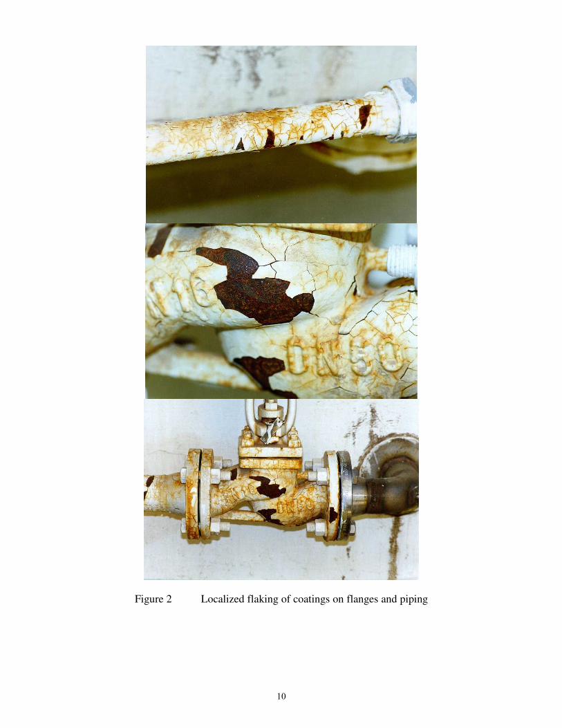
Figure 2 Localized flaking of coatings on flanges and piping
10

Figure 3 Coating deterioration and corrosion near welds
11
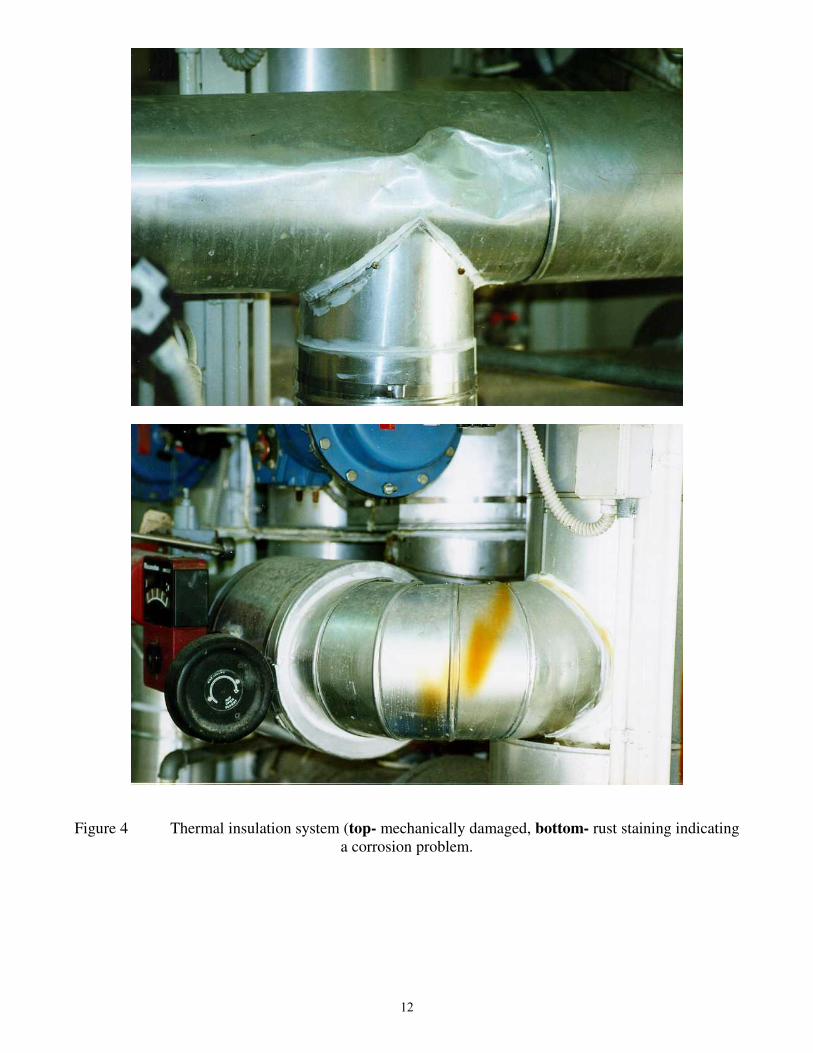
Figure 4 Thermal insulation system (top- mechanically damaged, bottom- rust staining indicating
a corrosion problem.
12

Figure 5 Severe corrosion attack of galvanized water tank.
Figure 6 Pitting corrosion and blisters with "white rust" zinc corrosion product.
13

Figure 7 Water spraying out from an ineffective leak repair location.
Figure 8 Exhaust pipes at the power house directing exhaust toward the water tanks.
14