08 slides cad site plan visual dictionary of architecture. van nostrandreinhold, 1995. ... microsoft...
TRANSCRIPT
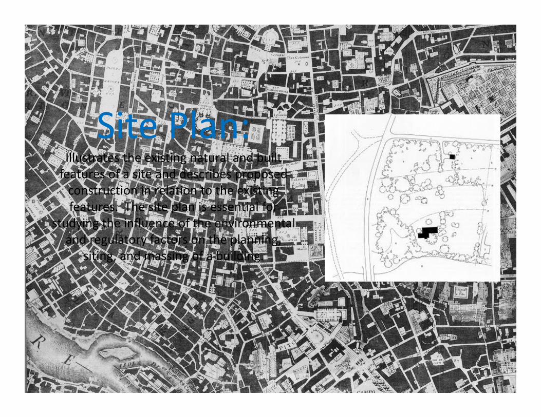
Site Plan:Illustrates the existing natural and built features of a site and describes proposed construction in relation to the existing features. The site plan is essential for
studying the influence of the environmental and regulatory factors on the planning,
siting, and massing of a building.

What is a Site Plan?A plan showing the form, location, and orientation of a building or group of buildings on a site; usually including the dimensions, contours, landscaping, and other significant features of the plot. Also call a plot plan. Ching, Francis. A Visual Dictionary of Architecture. Van Nostrand Reinhold, 1995.
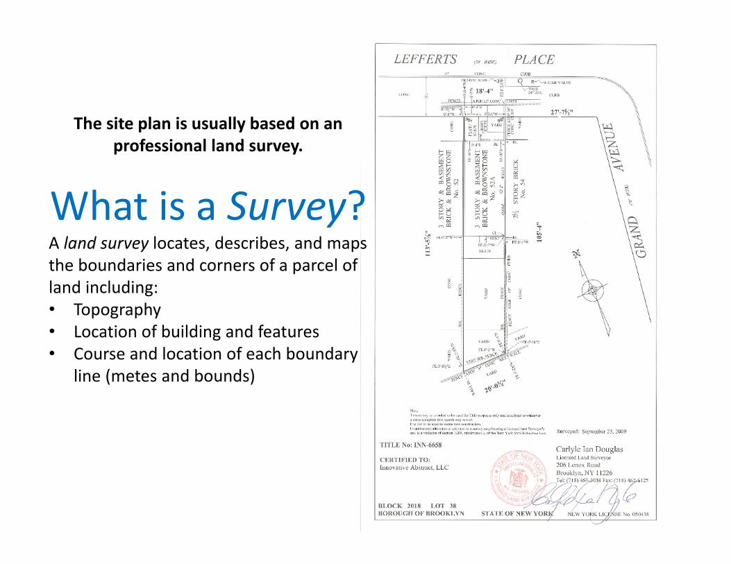
The site plan is usually based on an professional land survey.
What is a Survey?A land survey locates, describes, and maps the boundaries and corners of a parcel of land including:• Topography• Location of building and features• Course and location of each boundary
line (metes and bounds)

Zoning OrdinanceA site plan is used to demonstrate compliance with applicable codes and
zoning ordinances.
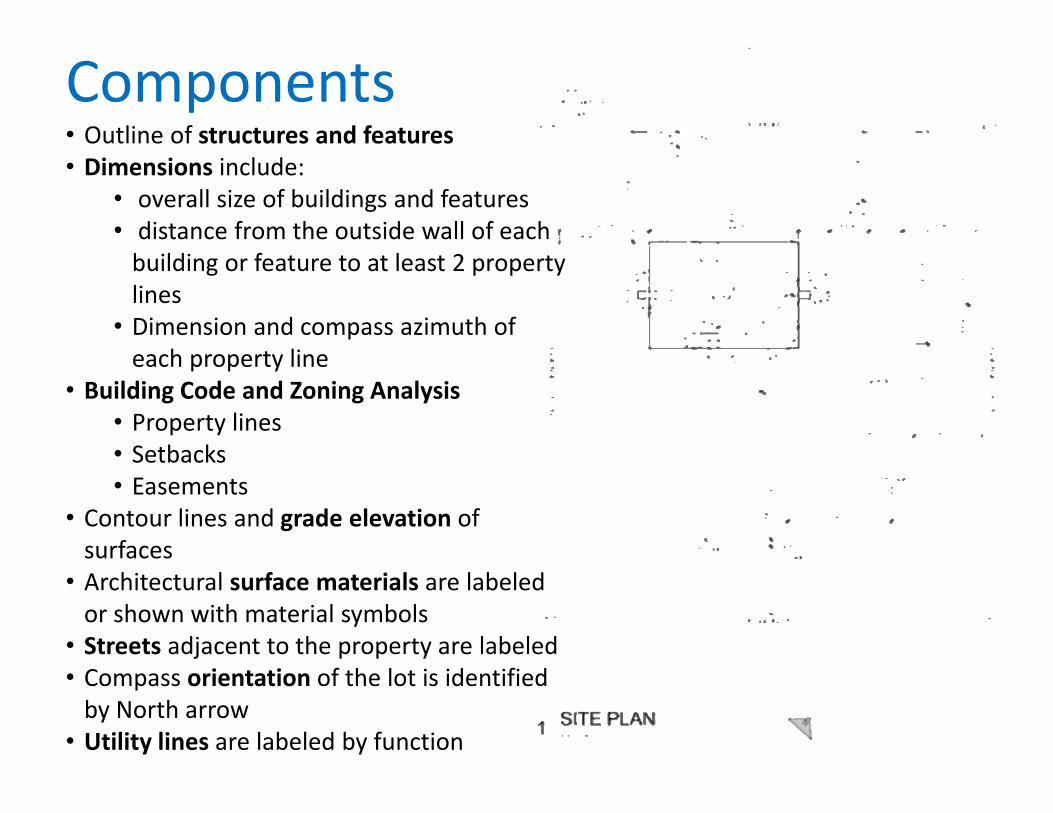
Components• Outline of structures and features• Dimensions include:
• overall size of buildings and features• distance from the outside wall of each building or feature to at least 2 property lines
• Dimension and compass azimuth of each property line
• Building Code and Zoning Analysis• Property lines• Setbacks• Easements
• Contour lines and grade elevation of surfaces
• Architectural surface materials are labeled or shown with material symbols
• Streets adjacent to the property are labeled• Compass orientation of the lot is identified by North arrow
• Utility lines are labeled by function

Margaret Esherick House, Louis Kahn, 1961.

Procedure1. Guidelines‐ layout page 2. Draft the objects • Start with guidelines• Complete with proper linewieghtsand linetypes
3. Annotation: Label and dimension the objects
4. Drawing Title and scale5. Titleblock and darken border6. Review
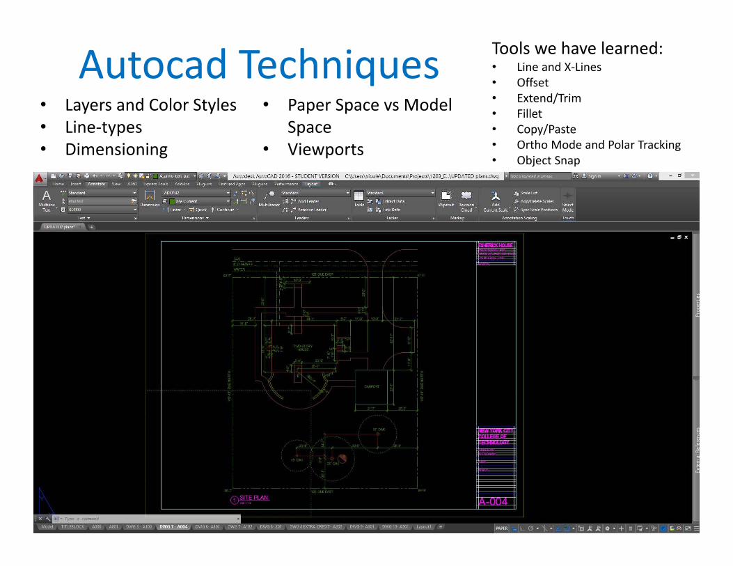
• Layers and Color Styles• Line‐types• Dimensioning
• Paper Space vs Model Space
• Viewports
Autocad Techniques Tools we have learned:• Line and X‐Lines• Offset• Extend/Trim• Fillet• Copy/Paste• Ortho Mode and Polar Tracking• Object Snap

Getting Started• Open a new drawing, save it!• Check your units: Architectural, Inches• You can customize your workspace with
options• Draft your linework in model space
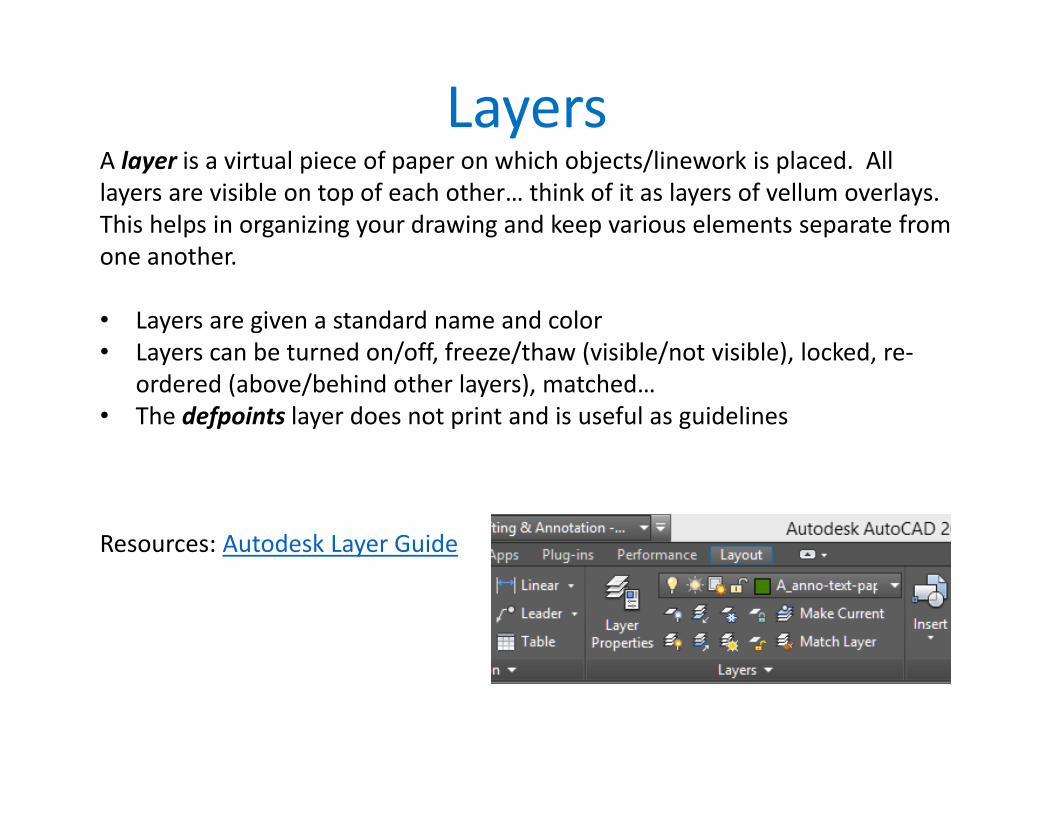
LayersA layer is a virtual piece of paper on which objects/linework is placed. All layers are visible on top of each other… think of it as layers of vellum overlays. This helps in organizing your drawing and keep various elements separate from one another.
• Layers are given a standard name and color• Layers can be turned on/off, freeze/thaw (visible/not visible), locked, re‐
ordered (above/behind other layers), matched…• The defpoints layer does not print and is useful as guidelines
Resources: Autodesk Layer Guide

Layer NamesFollow standard layer name formatting.

Layer ColorsLayers are assigned colors allowing for clear distinction between various elements.
Color can also be used to determine the plotted properties of lines. Colors can be assigned lineweights. See plot styles.

Line‐typesLayers are assigned line‐types, which function the same as with analog drafting techniques.
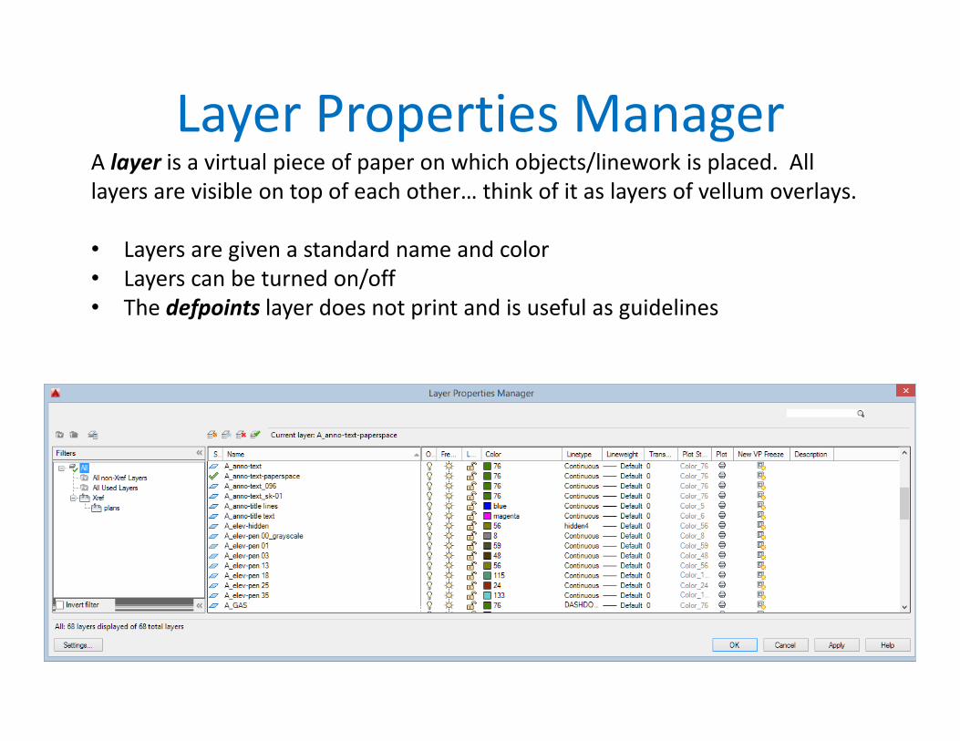
Layer Properties ManagerA layer is a virtual piece of paper on which objects/linework is placed. All layers are visible on top of each other… think of it as layers of vellum overlays.
• Layers are given a standard name and color• Layers can be turned on/off• The defpoints layer does not print and is useful as guidelines

Modifying PropertiesUse the Properties Palette (to open: select an object then right click)

DimensionsUse standard dimension techniques as discussed in regards to analog drafting. Autocad will help with the formatting.
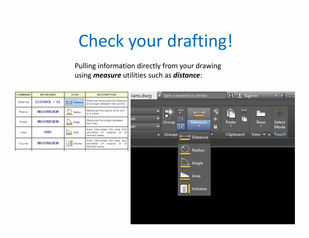
Check your drafting!Pulling information directly from your drawing using measure utilities such as distance:

Sheet Setup & Viewports• Use the Titleblock constructed in paper space for the previous assignment.• Use Page Setup Manager by right‐clicking paper space layout tab• Viewports create a view into
model space at a specific scale.

Scale FactorsWe draft at 1:1 in model space, full scale. We use drawing scales so that we can view an entire building or city block on a manageable sheet of paper.
Scale factors are the reciprocal of the drawing scale. We can use them for objects in model space that should appear the same size regardless of the scale of the drawing… text, dimensions, symbols.
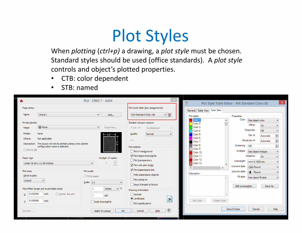
Plot StylesWhen plotting (ctrl+p) a drawing, a plot style must be chosen. Standard styles should be used (office standards). A plot style controls and object’s plotted properties.• CTB: color dependent • STB: named