072-090 models 180-240 models - lennoxpros.com · ahri certified to ahri standard 340/360-2007....
TRANSCRIPT
A I R C O N D I T I O N E R S
TST-CLASS™ SPLIT SYSTEM UNITS
R-410A - 60 HZ Bulletin No. 210524
September 2017 Supersedes November 2016
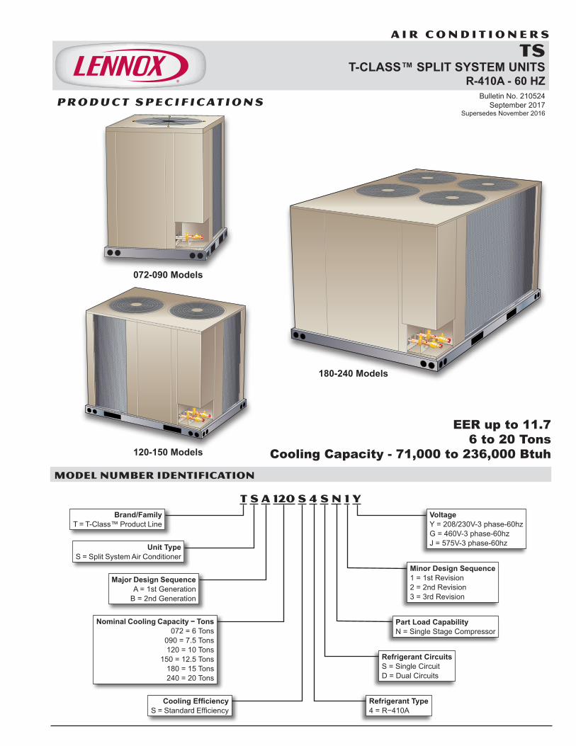
EER up to 11.76 to 20 Tons
Cooling Capacity - 71,000 to 236,000 BtuhMODEL NUMBER IDENTIFICATION
T S A 120 S 4 S N 1 Y
Major Design Sequence A = 1st Generation
B = 2nd Generation
Unit Type S = Split System Air Conditioner
Brand/Family T = T-Class™ Product Line
Cooling Efficiency S = Standard Efficiency
Minor Design Sequence 1 = 1st Revision 2 = 2nd Revision 3 = 3rd Revision
Voltage Y = 208/230V-3 phase-60hz G = 460V-3 phase-60hz J = 575V-3 phase-60hz
Nominal Cooling Capacity − Tons 072 = 6 Tons
090 = 7.5 Tons 120 = 10 Tons
150 = 12.5 Tons 180 = 15 Tons 240 = 20 Tons
Refrigerant Type 4 = R−410A
Refrigerant Circuits S = Single Circuit D = Dual Circuits
Part Load Capability N = Single Stage Compressor
072-090 Models
120-150 Models
180-240 Models
P R O D U C T S P E C I F I C AT I O N S
TS 6-20 TON AIR CONDITIONERS
TS 6 to 20 Ton R−410A Air Conditioners / Page 2
EQUIPMENT WARRANTY
Compressor - Limited warranty for five years in non-residential applications.All other covered components - One year in non-residential applications.Refer to Lennox Equipment Limited Warranty certificate for specific details.
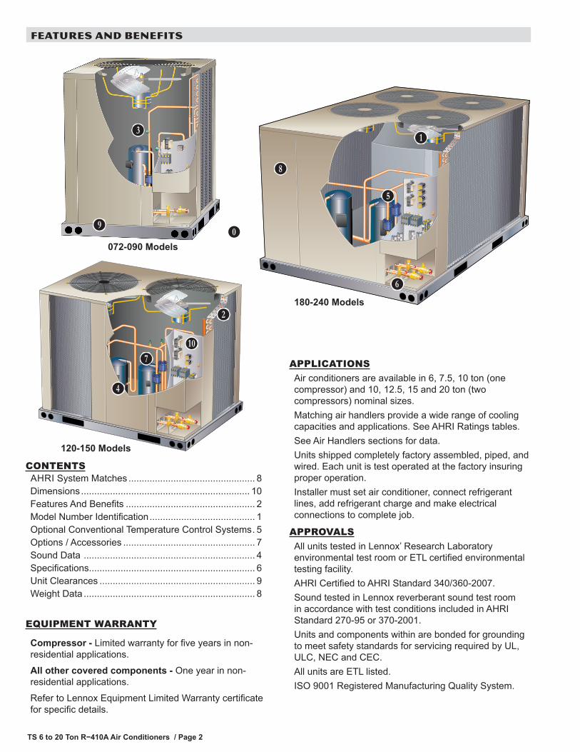
APPLICATIONSAir conditioners are available in 6, 7.5, 10 ton (one compressor) and 10, 12.5, 15 and 20 ton (two compressors) nominal sizes.Matching air handlers provide a wide range of cooling capacities and applications. See AHRI Ratings tables.See Air Handlers sections for data.Units shipped completely factory assembled, piped, and wired. Each unit is test operated at the factory insuring proper operation.Installer must set air conditioner, connect refrigerant lines, add refrigerant charge and make electrical connections to complete job.
APPROVALSAll units tested in Lennox’ Research Laboratory environmental test room or ETL certified environmental testing facility.AHRI Certified to AHRI Standard 340/360-2007.Sound tested in Lennox reverberant sound test room in accordance with test conditions included in AHRI Standard 270-95 or 370-2001.Units and components within are bonded for grounding to meet safety standards for servicing required by UL, ULC, NEC and CEC.All units are ETL listed.ISO 9001 Registered Manufacturing Quality System.
A
FEATURES AND BENEFITS
072-090 Models
120-150 Models
180-240 Models
B
C
D
E
F
G
H
I
J
K
CONTENTSAHRI System Matches ................................................ 8Dimensions ................................................................ 10Features And Benefits ................................................. 2Model Number Identification ........................................ 1Optional Conventional Temperature Control Systems . 5Options / Accessories .................................................. 7Sound Data ................................................................. 4Specifications............................................................... 6Unit Clearances ........................................................... 9Weight Data ................................................................. 8
TS 6 to 20 Ton R−410A Air Conditioners / Page 3
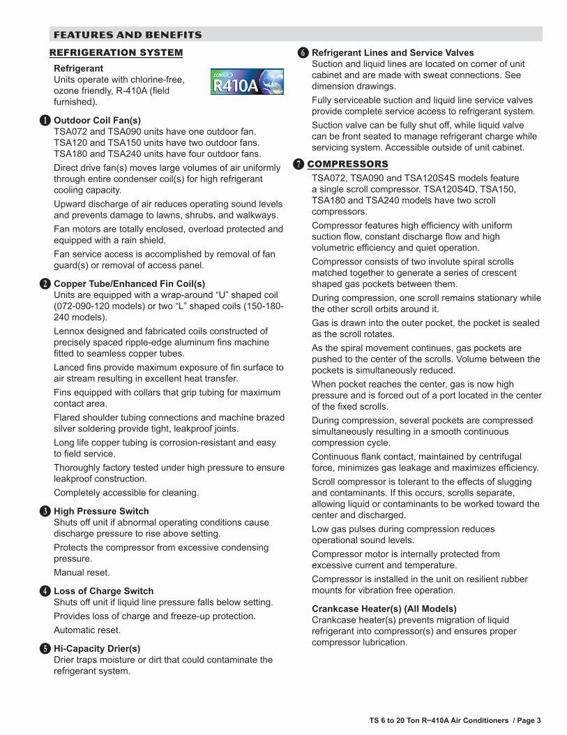
REFRIGERATION SYSTEMRefrigerantUnits operate with chlorine-free, ozone friendly, R-410A (field furnished).
Outdoor Coil Fan(s)TSA072 and TSA090 units have one outdoor fan. TSA120 and TSA150 units have two outdoor fans. TSA180 and TSA240 units have four outdoor fans.Direct drive fan(s) moves large volumes of air uniformly through entire condenser coil(s) for high refrigerant cooling capacity.Upward discharge of air reduces operating sound levels and prevents damage to lawns, shrubs, and walkways.Fan motors are totally enclosed, overload protected and equipped with a rain shield.Fan service access is accomplished by removal of fan guard(s) or removal of access panel.
Copper Tube/Enhanced Fin Coil(s)Units are equipped with a wrap-around “U” shaped coil (072-090-120 models) or two “L” shaped coils (150-180-240 models).Lennox designed and fabricated coils constructed of precisely spaced ripple-edge aluminum fins machine fitted to seamless copper tubes.Lanced fins provide maximum exposure of fin surface to air stream resulting in excellent heat transfer.Fins equipped with collars that grip tubing for maximum contact area.Flared shoulder tubing connections and machine brazed silver soldering provide tight, leakproof joints.Long life copper tubing is corrosion-resistant and easy to field service.Thoroughly factory tested under high pressure to ensure leakproof construction.Completely accessible for cleaning.
High Pressure SwitchShuts off unit if abnormal operating conditions cause discharge pressure to rise above setting.Protects the compressor from excessive condensing pressure.Manual reset.
Loss of Charge SwitchShuts off unit if liquid line pressure falls below setting.Provides loss of charge and freeze-up protection.Automatic reset.
Hi-Capacity Drier(s)Drier traps moisture or dirt that could contaminate the refrigerant system.
B
C
D
E
F
FEATURES AND BENEFITS
Refrigerant Lines and Service ValvesSuction and liquid lines are located on corner of unit cabinet and are made with sweat connections. See dimension drawings.Fully serviceable suction and liquid line service valves provide complete service access to refrigerant system.Suction valve can be fully shut off, while liquid valve can be front seated to manage refrigerant charge while servicing system. Accessible outside of unit cabinet.
COMPRESSORSTSA072, TSA090 and TSA120S4S models feature a single scroll compressor. TSA120S4D, TSA150, TSA180 and TSA240 models have two scroll compressors.Compressor features high efficiency with uniform suction flow, constant discharge flow and high volumetric efficiency and quiet operation.Compressor consists of two involute spiral scrolls matched together to generate a series of crescent shaped gas pockets between them.During compression, one scroll remains stationary while the other scroll orbits around it.Gas is drawn into the outer pocket, the pocket is sealed as the scroll rotates.As the spiral movement continues, gas pockets are pushed to the center of the scrolls. Volume between the pockets is simultaneously reduced.When pocket reaches the center, gas is now high pressure and is forced out of a port located in the center of the fixed scrolls.During compression, several pockets are compressed simultaneously resulting in a smooth continuous compression cycle.Continuous flank contact, maintained by centrifugal force, minimizes gas leakage and maximizes efficiency.Scroll compressor is tolerant to the effects of slugging and contaminants. If this occurs, scrolls separate, allowing liquid or contaminants to be worked toward the center and discharged.Low gas pulses during compression reduces operational sound levels.Compressor motor is internally protected from excessive current and temperature.Compressor is installed in the unit on resilient rubber mounts for vibration free operation.
Crankcase Heater(s) (All Models)Crankcase heater(s) prevents migration of liquid refrigerant into compressor(s) and ensures proper compressor lubrication.
G
H
TS 6 to 20 Ton R−410A Air Conditioners / Page 4
FEATURES AND BENEFITS
CABINETHeavy-gauge, pre-painted steel cabinet provides superior rust and corrosion protection.Removable panels allow access for unit servicing.Heavy duty steel base channels raise the unit off of mounting surface away from damaging moisture.Unit lifting holes and forklift slots furnished in base rails.See dimension drawings.
Control BoxControl box located in separate compartment in unit cabinet .All controls are pre-wired at the factory.Control box is large enough for field installed DDC or other field supplied control modules.
Options/Accessories
Factory InstalledCorrosion ProtectionPolymeric epoxy coating that is deposited by electrical transport (electrophoresis), using a process known as electrocoat (e-coat). Available for enhanced coil corrosion protection. Factory installed on the condenser coil. Painted base pan is provided with this option.
Field InstalledCombination Coil/Hail GuardsHeavy gauge steel frame painted to match cabinet with expanded metal mesh to protect the outdoor coil from damage.
I
J
K
CONTROLS
Options/Accessories
Field InstalledL Connection® NetworkComplete building automation control system for single or multi-zone applications. Options include local interface, software for local or remote communication, and hardware for networking other control functions.See L Connection Network Product Specifications Bulletin for details.
Network Thermostat ControllerRequired for use with the L Connection Network. Monitors and controls system operation.
Low Ambient ControlAir conditioning units operate satisfactorily down to 30ºF outdoor air temperature without any additional controls.Low Ambient Control Kit can be field installed, allowing unit operation down to 0ºF.
ThermostatThermostat is not furnished with unit and must be ordered extra.See page 5, individual Thermostat bulletins and Lennox Price Book.
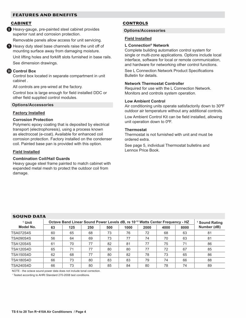
SOUND DATA 1 Unit
Model No.Octave Band Linear Sound Power Levels dB, re 10-12 Watts Center Frequency - HZ 1 Sound Rating
Number (dB)63 125 250 500 1000 2000 4000 8000TSA072S4S 60 65 68 73 76 72 68 63 81TSA090S4S 56 64 69 73 77 74 70 63 81TSA120S4S 61 70 77 82 81 77 75 71 86TSA120S4D 65 71 77 80 80 77 72 67 85TSA150S4D 62 68 77 80 82 78 73 65 86TSA180S4D 66 73 80 83 83 79 74 66 88TSA240S4D 66 73 80 85 84 80 78 74 89NOTE - the octave sound power data does not include tonal correction.1 Tested according to AHRI Standard 270-2008 test conditions.
TS 6 to 20 Ton R−410A Air Conditioners / Page 5
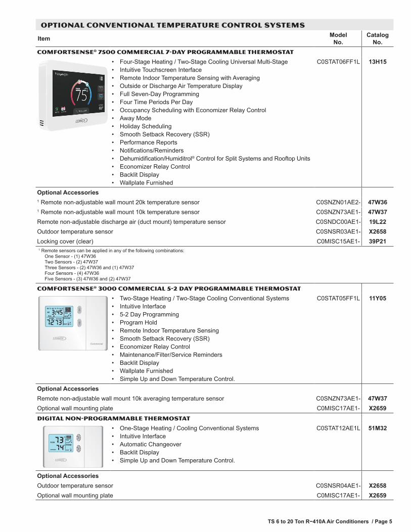
OPTIONAL CONVENTIONAL TEMPERATURE CONTROL SYSTEMS
Item Model No.
Catalog No.
COMFORTSENSE® 7500 COMMERCIAL 7-DAY PROGRAMMABLE THERMOSTAT
• Four-Stage Heating / Two-Stage Cooling Universal Multi-Stage• Intuitive Touchscreen Interface• Remote Indoor Temperature Sensing with Averaging• Outside or Discharge Air Temperature Display• Full Seven-Day Programming• Four Time Periods Per Day• Occupancy Scheduling with Economizer Relay Control• Away Mode• Holiday Scheduling• Smooth Setback Recovery (SSR)• Performance Reports• Notifications/Reminders• Dehumidification/Humiditrol® Control for Split Systems and Rooftop Units• Economizer Relay Control• Backlit Display• Wallplate Furnished
C0STAT06FF1L 13H15
Optional Accessories1 Remote non-adjustable wall mount 20k temperature sensor C0SNZN01AE2- 47W361 Remote non-adjustable wall mount 10k temperature sensor C0SNZN73AE1- 47W37Remote non-adjustable discharge air (duct mount) temperature sensor C0SNDC00AE1- 19L22Outdoor temperature sensor C0SNSR03AE1- X2658Locking cover (clear) C0MISC15AE1- 39P211 R emote sensors can be applied in any of the following combinations:
One Sensor - (1) 47W36 Two Sensors - (2) 47W37 Three Sensors - (2) 47W36 and (1) 47W37 Four Sensors - (4) 47W36 Five Sensors - (3) 47W36 and (2) 47W37
COMFORTSENSE® 3000 COMMERCIAL 5-2 DAY PROGRAMMABLE THERMOSTAT
MAINT
Commercial
• Two-Stage Heating / Two-Stage Cooling Conventional Systems• Intuitive Interface• 5-2 Day Programming• Program Hold• Remote Indoor Temperature Sensing• Smooth Setback Recovery (SSR)• Economizer Relay Control• Maintenance/Filter/Service Reminders• Backlit Display• Wallplate Furnished• Simple Up and Down Temperature Control.
C0STAT05FF1L 11Y05
Optional AccessoriesRemote non-adjustable wall mount 10k averaging temperature sensor C0SNZN73AE1- 47W37Optional wall mounting plate C0MISC17AE1- X2659DIGITAL NON-PROGRAMMABLE THERMOSTAT
• One-Stage Heating / Cooling Conventional Systems• Intuitive Interface• Automatic Changeover• Backlit Display• Simple Up and Down Temperature Control.
C0STAT12AE1L 51M32
Optional AccessoriesOutdoor temperature sensor C0SNSR04AE1- X2658Optional wall mounting plate C0MISC17AE1- X2659

TS 6 to 20 Ton R−410A Air Conditioners / Page 6
SPECIFICATIONS - 6 - 7.5 TONGeneral Data
Model No. TSA072S4S TSA090S4SNominal Size - Tons 6 7.5
Connections (sweat)
Liquid line - in. (o.d) (1) 5/8 (1) 5/8Suction line - in. (o.d) (1) 1-1/8 (1) 1-1/8
Refrigerant (R-410A) Factory installed R-410A holding charge (2 lb. per stage)1 Field provided charge with 25 ft. line set 10 lbs. 0 oz. 15 lbs. 0 oz.
Condenser Coil
Net face area - sq. ft. Outer coil 29.3 29.3Inner coil - - - 28.4
Tube diameter - in. & no. of rows 3/8 - 1 3/8 - 2Fins per inch 20 20
Condenser Fan(s)
Diameter - in. & no. of blades (1) 24 - 3 (1) 24 - 4Motor hp (1) 1/3 (1) 1/2
Total air volume - cfm 5100 5600Rpm 1075 1075
Watts 430 580ELECTRICAL DATA
Line voltage data - 60 hz - 3 phase 208/230V 460V 575V 208/230V 460V 575V2 Maximum Overcurrent Protection (amps) 45 20 15 50 25 20
3 Minimum circuit ampacity 27 14 11 35 17 13Compressor No. of Compressors 1 1 1 1 1 1
Rated load amps 19 9.7 7.4 25 12.2 9Locked rotor amps 123 62 50 164 100 78
Condenser Fan Motor (1 phase)
No. of motors 1 1 1 1 1 1Full load amps 2.4 1.3 1 3 1.5 1.2
Locked rotor amps 4.7 2.4 1.9 6 3 2.9NOTE - Extremes of operating range are plus and minus 10% of line voltage.1 Refer to the Lennox Refrigerant Piping Manual to determine refrigerant charge required with longer length refrigerant lines.2 HACR type circuit breaker or fuse.3 Refer to National or Canadian Electrical Code manual to determine wire, fuse and disconnect size requirements.
SPECIFICATIONS - 10 TONGeneral Data
Model No. TSA120S4S TSA120S4DNominal Size - Tons 10 10
Connections (sweat)
Liquid line - in. (o.d) (1) 5/8 (2) 5/8Suction line - in. (o.d) (1) 1-3/8 (2) 1-1/8
Refrigerant (R-410A) Factory installed R-410A holding charge (2 lb. per stage)1 Field provided charge with 25 ft. line set 16 lbs. 0 oz. 18 lbs. 0 oz.
Condenser Coil
Net face area - sq. ft. Outer coil 29.3 29.3Inner coil 28.4 28.4
Tube diameter - in. & no. of rows 3/8 - 2 3/8 - 2Fins per inch 20 20
Condenser Fan(s)
Diameter - in. & no. of blades (2) 24 - 3 (2) 24 - 3Motor hp (2) 1/3 (2) 1/3
Total air volume - cfm 8300 8300Rpm 1075 1075
Watts 830 830ELECTRICAL DATA
Line voltage data - 60 hz - 3 phase 208/230V 460V 575V 208/230V 460V 575V2 Maximum Overcurrent Protection (amps) 70 40 25 50 25 20
3 Minimum circuit ampacity 43 24 18 41 21 15Compressor No. of Compressors 1 1 1 2 2 2
Rated load amps (total) 30.1 16.7 12.2 18 (32) 7.8 (15.6) 5.7 (11.4)Locked rotor amps (total) 225 114 80 110 (220) 52 (104) 38.9 (77.8)
Condenser Fan Motor (1 phase)
No. of motors 2 2 2 2 2 2Full load amps (total) 2.4 (4.8) 1.3 (2.6) 1 (2) 2.4 (4.8) 1.3 (2.6) 1 (2)
Locked rotor amps (total) 4.7 (9.4) 2.4 (4.8) 1.9 (3.8) 4.7 (9.4) 2.4 (4.8) 1.9 (3.8)NOTE - Extremes of operating range are plus and minus 10% of line voltage.1 Refer to the Lennox Refrigerant Piping Manual to determine refrigerant charge required with longer length refrigerant lines.2 HACR type circuit breaker or fuse.3 Refer to National or Canadian Electrical Code manual to determine wire, fuse and disconnect size requirements.

TS 6 to 20 Ton R−410A Air Conditioners / Page 7
SPECIFICATIONS - 12.5 - 20 TONGeneral Data
Model No. TSA150S4D TSA180S4D TSA240S4DNominal Size - Tons 12.5 15 20
Connections (sweat)
Liquid line - in. (o.d) (2) 5/8 (2) 5/8 (2) 5/8Suction line - in. (o.d) (2) 1-1/8 (2) 1-1/8 (2) 1-3/8
Refrigerant (R-410A) Factory installed R-410A holding charge (2 lb. per stage)1 Field provided charge with 25 ft. line set 19 lbs. 0 oz. 27 lbs. 0 oz. 33 lbs. 0 oz.
Condenser Coil
Net face area - sq. ft. Outer coil 34.2 58.7 58.7Inner coil 33.3 57.7 57.7
Tube diameter - in. & no. of rows 3/8 - 2 3/8 - 2 3/8 - 2Fins per inch 20 20 20
Condenser Fan(s)
Diameter - in. & no. of blades (2) 24 - 4 (4) 24 - 3 (4) 24 - 3Motor hp (2) 1/2 (4) 1/3 (4) 1/3
Total air volume - cfm 10,300 16,600 16,600Rpm 1075 1075 1075
Watts 1130 1660 1660
ELECTRICAL DATALine voltage data - 60 hz - 3 phase 208/230V 460V 575V 208/230V 460V 575V 208/230V 460V 575V
2 Maximum Overcurrent Protection (amps) 60 30 25 90 40 30 100 50 403 Minimum circuit ampacity 49 25 20 66 33 25 78 43 32
Compressor No. of Compressors 2 2 2 2 2 2 2 2 2Rated load amps
(total)19
(38)9.7
(19.4)7.4
(14.8)25
(50)12.2
(24.4)9
(18)30.1 60.2)
16.7 (33.4)
12.2 (24.8)
Locked rotor amps (total)
123 (246)
62 (124)
50 (100)
164 (328)
100 (200)
78 (156)
225 (450)
114 (228)
80 (160)
Condenser Fan Motor (1 phase)
No. of motors 2 2 2 4 4 4 4 4 4Full load amps
(total)3
(6)1.5 (3)
1.2 (2.4)
2.4 (9.6)
1.3 (5.2)
1 (4)
2.4 (9.6)
1.3 (5.2)
1 (4)
Locked rotor amps (total)
6 (12)
3 (6)
2.9 (5.8)
4.7 (18.8)
2.4 (9.6)
1.9 (7.6)
4.7 (18.8)
2.4 (9.6)
1.9 (7.6)
NOTE - Extremes of operating range are plus and minus 10% of line voltage.1 Refer to the Lennox Refrigerant Piping Manual to determine refrigerant charge required with longer length refrigerant lines.2 HACR type circuit breaker or fuse.3 Refer to National or Canadian Electrical Code manual to determine wire, fuse and disconnect size requirements.
OPTIONS / ACCESSORIESItem Catalog
No.072S4S 090S4S 120S4S 120S4D 150S4D 180S4D 240S4D
CABINET
Combined Coil/Hail Guards T2GARD51L-1 13T29 X XT2GARD51M11 13T30 X XT2GARD51M21 13T32 XT2GARD51N-1 13T37 X X
Corrosion Protection Factory O O O O O O OCONTROLS
Low Ambient Control (0ºF) T2CWKT01LM1- 44W17 X X XT2CWKT02M-1- 44W18 X XT2CWKT03N-1- 44W19 X X
L Connection® Building Automation System - - - X X X X X X XNetwork Thermostat Controller C0CTRL07AE1L 17M10 X X X X X X XNOTE - The catalog and model numbers that appear here are for ordering field installed accessories only.O - Factory Installed with extended lead time.X - Field Installed
TS 6 to 20 Ton R−410A Air Conditioners / Page 8
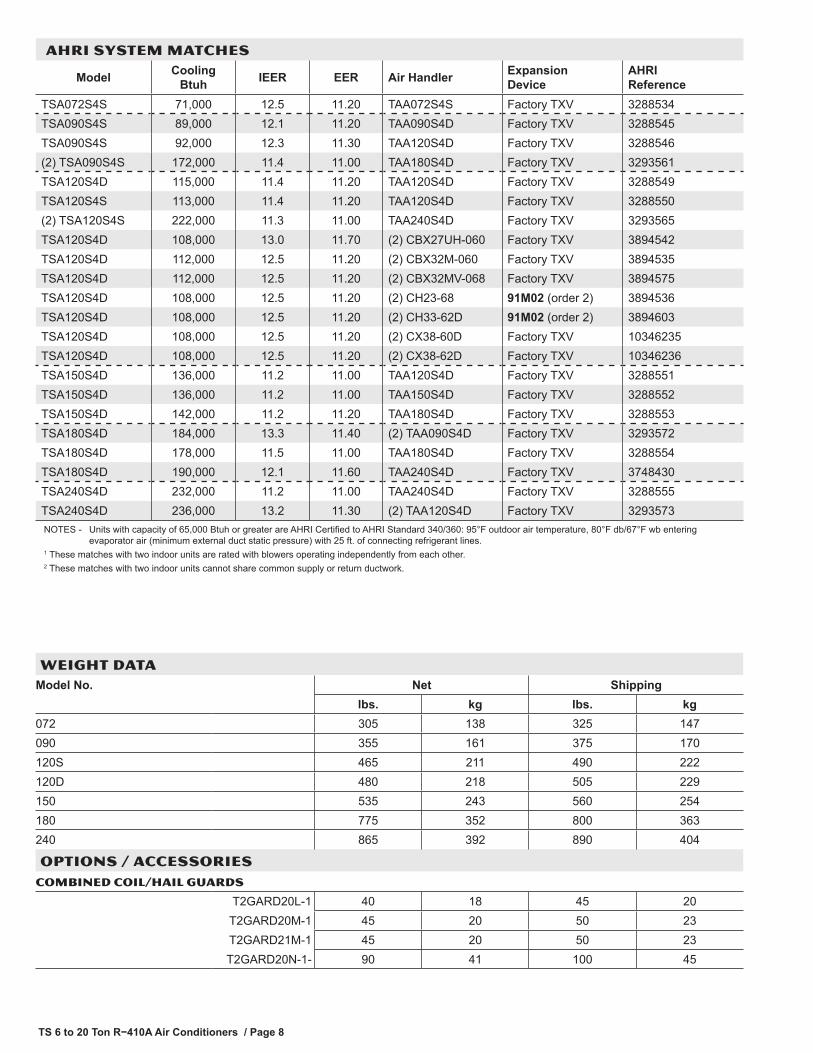
WEIGHT DATAModel No. Net Shipping
lbs. kg lbs. kg072 305 138 325 147090 355 161 375 170120S 465 211 490 222120D 480 218 505 229150 535 243 560 254180 775 352 800 363240 865 392 890 404
OPTIONS / ACCESSORIESCOMBINED COIL/HAIL GUARDS
T2GARD20L-1 40 18 45 20T2GARD20M-1 45 20 50 23T2GARD21M-1 45 20 50 23T2GARD20N-1- 90 41 100 45
AHRI SYSTEM MATCHES
Model Cooling Btuh IEER EER Air Handler Expansion
DeviceAHRI Reference
TSA072S4S 71,000 12.5 11.20 TAA072S4S Factory TXV 3288534TSA090S4S 89,000 12.1 11.20 TAA090S4D Factory TXV 3288545TSA090S4S 92,000 12.3 11.30 TAA120S4D Factory TXV 3288546(2) TSA090S4S 172,000 11.4 11.00 TAA180S4D Factory TXV 3293561TSA120S4D 115,000 11.4 11.20 TAA120S4D Factory TXV 3288549TSA120S4S 113,000 11.4 11.20 TAA120S4D Factory TXV 3288550(2) TSA120S4S 222,000 11.3 11.00 TAA240S4D Factory TXV 3293565TSA120S4D 108,000 13.0 11.70 (2) CBX27UH-060 Factory TXV 3894542TSA120S4D 112,000 12.5 11.20 (2) CBX32M-060 Factory TXV 3894535TSA120S4D 112,000 12.5 11.20 (2) CBX32MV-068 Factory TXV 3894575TSA120S4D 108,000 12.5 11.20 (2) CH23-68 91M02 (order 2) 3894536TSA120S4D 108,000 12.5 11.20 (2) CH33-62D 91M02 (order 2) 3894603TSA120S4D 108,000 12.5 11.20 (2) CX38-60D Factory TXV 10346235TSA120S4D 108,000 12.5 11.20 (2) CX38-62D Factory TXV 10346236TSA150S4D 136,000 11.2 11.00 TAA120S4D Factory TXV 3288551TSA150S4D 136,000 11.2 11.00 TAA150S4D Factory TXV 3288552TSA150S4D 142,000 11.2 11.20 TAA180S4D Factory TXV 3288553TSA180S4D 184,000 13.3 11.40 (2) TAA090S4D Factory TXV 3293572TSA180S4D 178,000 11.5 11.00 TAA180S4D Factory TXV 3288554TSA180S4D 190,000 12.1 11.60 TAA240S4D Factory TXV 3748430TSA240S4D 232,000 11.2 11.00 TAA240S4D Factory TXV 3288555TSA240S4D 236,000 13.2 11.30 (2) TAA120S4D Factory TXV 3293573NOTES - Units with capacity of 65,000 Btuh or greater are AHRI Certified to AHRI Standard 340/360: 95°F outdoor air temperature, 80°F db/67°F wb entering
evaporator air (minimum external duct static pressure) with 25 ft. of connecting refrigerant lines.1 These matches with two indoor units are rated with blowers operating independently from each other.2 These matches with two indoor units cannot share common supply or return ductwork.

TS 6 to 20 Ton R−410A Air Conditioners / Page 9
UNIT CLEARANCES - INCHES (MM)
TSA072 and TSA090
CONTROLBOX ACCESS
30(762)
SeeNOTES
36(914)
SeeNOTES
NOTES:Clearance to one of the remaining two sides may be 12 in.(305 mm) and the final side may be 6 in. (152 mm).A clearance of 24 in. (610 mm) must be maintained betweentwo units.48 in. (1219 mm) clearance required on top of unit.
TSA120 and TSA150
CONTROLBOX ACCESS
NOTES:Clearance to one of the remaining two sides may be 12in. (305 mm) and the final side may be 6 in. (152 mm).A clearance of 24 in. (610 mm) must be maintained be-tween two units.48 in. (1219 mm) clearance required on top of unit.
SeeNOTES
SeeNOTES
30(762)
36(914)
TSA180 and TSA240
CONTROLBOX ACCESS
NOTES:Clearance to one of the remaining two sides maybe 12 in. (305 mm) and the final side may be 6 in.(152 mm).A clearance of 24 in. (610 mm) must be main-tained between two units.48 in. (1219 mm) clearance required on top of unit.
SeeNOTES
SeeNOTES
36(914)
30(762)
TS 6 to 20 Ton R−410A Air Conditioners / Page 10
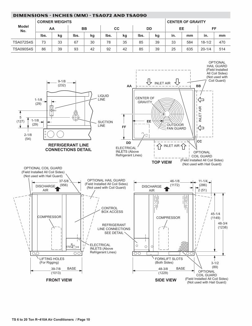
DIMENSIONS - INCHES (MM) - TSA072 AND TSA090
(Not used with Hail Guard)OPTIONAL COIL GUARD
(Field Installed All Coil Sides)(Not used with Hail Guard)
DISCHARGEAIR
48-3/8(1229)
46-1/8(1172)
39-7/8(1013)
9-1/8(232)
1-1/8(29)
2-1/8(54)
SUCTIONLINE
LIQUIDLINE
BBAA
CCDD
37-5/8(956)
48-3/4(1238)
3-1/2(89)
45-1/4(1149)
REFRIGERANTLINE CONNECTIONS
SEE DETAIL
REFRIGERANT LINECONNECTIONS DETAIL
EEFF
CONTROLBOX ACCESS
COMPRESSOR COMPRESSOR
CENTER OFGRAVITY
INLE
T A
IR
INLET AIR
DISCHARGEAIR
BASE
LIFTING HOLES(For Rigging)
FORKLIFT SLOTS(Both Sides)
TOP VIEW
WEIV EDISWEIV TNORF
OUTDOORFAN GUARD
1-1/8(29)
BASE
ELECTRICALINLETS (AboveRefrigerant Lines)
INLET AIR
5(127)
ELECTRICAL INLETS (Above Refrigerant Lines)
11-1/4(286)
2 (51)
OPTIONAL HAIL GUARD(Field Installed All Coil Sides)
(Not used with Coil Guard)
OPTIONALHAIL GUARD(Field InstalledAll Coil Sides)(Not used with
Coil Guard)
OPTIONALCOIL GUARD
(Field Installed All Coil Sides)
OPTIONALCOIL GUARD
(Field Installed All Coil Sides)(Not used with Hail Guard)
Model No.
CORNER WEIGHTS CENTER OF GRAVITY
AA BB CC DD EE FF
lbs. kg lbs. kg lbs. kg lbs. kg in. mm in. mm
TSA072S4S 73 33 67 30 78 35 85 39 33 584 18-1/2 470
TSA090S4S 86 39 93 42 92 42 85 39 25 635 20-1/4 514

TS 6 to 20 Ton R−410A Air Conditioners / Page 11
DIMENSIONS - INCHES (MM) - TSA120 AND TSA150
DISCHARGEAIR
REFRIGERANTLINE CONNECTIONS
SEE DETAIL
DISCHARGEAIR
41-3/8(1051)
LIFTING HOLES(For Rigging)
SIDE VIEW
43-5/8(1108)
48-3/4(1238)
3-1/2(89)
45-1/4(1149)
BASE60-1/8(1527)
57-7/8(1470)
COMPRESSOR
BASE
FRONT VIEW
FORKLIFT SLOTS(Both Sides)
CONTROLBOX ACCESS
ELECTRICAL INLETS (Above Refrigerant Lines)
TOP VIEW
FFEE IN
LET
AIR
INLET AIR
BBAA
CCDD
CENTER OFGRAVITY
ELECTRICALINLETS (AboveRefrigerant Lines)
OUTDOOR FANGUARDS (2)
INLET AIR
OPTIONALCOIL GUARD(Field InstalledAll Coil Sides)(Not used with
Hail Guard)
2(51)
OPTIONAL HAIL GUARD(Field Installed All Coil Sides)
(Not used with Coil Guard)
OPTIONAL HAIL GUARD(Field Installed All Coil Sides)
(Not used with Coil Guard)
5(127)
2-1/8(54)
9-1/8(232)
1-1/8(29)
3-3/4(95)
6-1/2(165)
SUCTIONLINES
LIQUIDLINES
SINGLE STAGETSA120S4S
STAGE 1TSA120S4DTSA150S4D
STAGE 2TSA120S4DTSA150S4D
1-1/8(29)
REFRIGERANT LINECONNECTIONS DETAIL
11-1/4(286)
(Not used withHail Guard)
OPTIONAL COIL GUARD(Field Installed All Coil Sides)
(Not used with Hail Guard)
OPTIONALCOIL GUARD(Field InstalledAll Coil Sides)
Model No.
CORNER WEIGHTS CENTER OF GRAVITY
AA BB CC DD EE FF
lbs. kg lbs. kg lbs. kg lbs. kg in. mm in. mm
TSA120S4S 136 62 121 55 96 44 108 49 20-1/2 521 33-1/2 851
TSA120S4D 120 54 112 51 124 56 133 60 21 533 28-1/2 724
TSA150S4D 152 69 117 53 117 53 152 69 19 483 30 762

TS 6 to 20 Ton R−410A Air Conditioners / Page 12
DIMENSIONS - INCHES (MM) - TSA180 AND TSA240
1-1/8(29)
DISCHARGEAIR
INLE
TA
IR
86-1/2(2197)
60-1/8(1527)
57-7/8(1470)
CONTROLBOX ACCESS
BASE
LIFTING HOLES(For Rigging)
FRONT VIEW
5(127)
2-1/8(54)
9-1/8(232)
1-1/8(29)
TOP VIEW
FORKLIFT SLOTS(Both Sides)
SIDE VIEW
88-3/4(2254)
48-3/4(1238)
3-1/2(89)
45-1/4(1149)
FF
EE
CENTER OFGRAVITY
AA BB
CCDD
3-3/4(95)
6-1/2(165)
BASE
COMPRESSOR
SUCTIONLINE (2)
LIQUIDLINE (2)
OUTDOOR FANGUARDS (4)
REFRIGERANT LINECONNECTIONS DETAIL
INLETAIR
INLETAIR
ELECTRICALINLETS (AboveRefrigerant Lines)
DISCHARGEAIR
REFRIGERANTLINE CONNECTIONS
SEE DETAIL
ELECTRICAL INLETS (Above Refrigerant Lines)
STAGE 1 STAGE 2
OPTIONAL COIL GUARD(Field Installed All Coil Sides)
(Not used with Hail Guard)
2(51)
OPTIONALHAIL GUARD(Field InstalledAll Coil Sides)(Not used with
Coil Guard)
OPTIONALHAIL GUARD(Field InstalledAll Coil Sides)(Not used with
Coil Guard)
11-1/4(286)
(Not used withHail Guard)OPTIONAL COIL GUARD
(Field Installed All Coil Sides)(Not used with Hail Guard)
OPTIONALCOIL GUARD(Field InstalledAll Coil Sides)
Model No.
CORNER WEIGHTS CENTER OF GRAVITY
AA BB CC DD EE FF
lbs. kg lbs. kg lbs. kg lbs. kg in. mm in. mm
TSA180S4D 223 101 166 75 178 81 238 108 29 737 38 965
TSA240S4D 265 120 197 89 197 89 265 120 30 762 38 965


REVISIONS
Sections Description of Change
AHRI System Matches Updated.
REVISIONS
NOTE - Due to Lennox’ ongoing commitment to quality, Specifications, Ratings and Dimensions subject to change without notice and without incurring liability. Improper installation, adjustment, alteration, service or maintenance can cause property damage or personal injury. Installation and service must be performed by a qualified installer and servicing agency. ©2017 Lennox Industries, Inc.
Visit us at www.lennox.com For the latest technical information, www.lennoxcommercial.com Contact us at 1-800-4-LENNOX