06411 micro nucleating bubble engine team members steven nathenson joseph pawelski joaquin pelaez...
Post on 21-Dec-2015
216 views
TRANSCRIPT

06411 Micro Nucleating Bubble Engine
Team MembersSteven NathensonJoseph PawelskiJoaquin PelaezAndrew PionessaBrian Thomson
Project SponsorsDr. CrassidisDr. Kandlikar
Project CoordinatorDr. Walter

Introduction / Project Goals
• Millimeter scale
• Piston like design
• Performance comparison
• Small budget
• Control bubble production
• Mobile
• TO GRADUATE

Alternate Designs
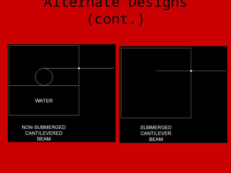
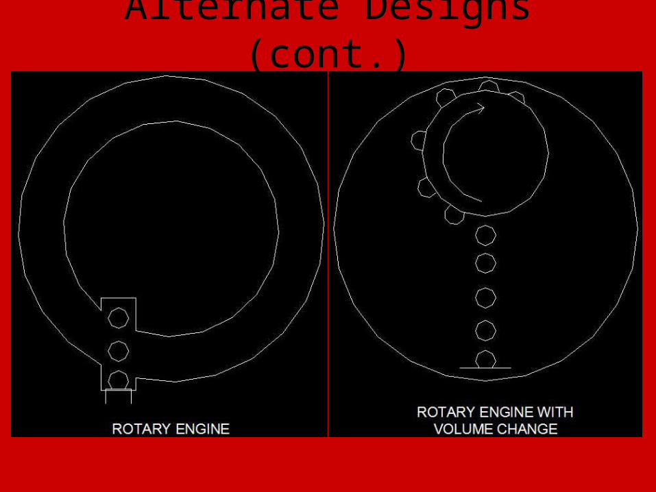
Alternate Designs (cont.)

Alternate Designs (cont.)
Alternate Designs (cont.)

Major / Critical Specifications• Customer Requirements / Objectives
– Be portable and lightweight– Work on principles of bubble nucleation to produce mechanical
oscillations of a piston• Determine appropriate fluid for ideal bubble behavior• Utilize a power supply or a battery in conjunction with a control system to
regulate heater and control bubble growth– Utilize a miniature heating element
• May need to be protected so it does not break or fracture• Must be easily replaced
– Stay within the budget– Create a millimeter-sized engine– Create a proof-of-concept
• Theoretically prove engine design• Create and test a working engine• Benchmark operational specifications, such as operational frequency,
efficiency, and operation time– Runtime
• Must run for about 20 seconds• The liquid reservoir might need be cooled via a heat exchanger to allow for
longer runtimes– Reduce friction between piston and casing

Major / Critical Specifications (cont.)• Functional Requirements
– Contained within (1 ft3) volume– Piston size of 5-10 mm– Must function at around 5-10 Hz
• Design Specifications to Date– Pyrex Cylinder
• ID: 0.218”• OD: .0375”• Operating Temp: -20°F to +446°F
– Teflon Piston– Platinum wire heating element
• OD: 0.002” • Resistivity: 10.6 x10⁻⁸ W·m• Length: 1-2 mm
– Base plate with two aluminum electrodes

Feasibility / Technical Concerns
• Piston design – most feasible– Easy to manufacture– Simple– Easy to test– Smallest time of development– Preferred design of sponsor– Risk assessment contained within Pre-Read Package
• QFD Analysis yields concerns– Bubble control– Piston displacement– Piston size– Power input– Accurate theoretical models*
*Not contained within QFD analysis

Heater• During the brainstorming portion of the project, there were several
heater ideas proposed. The initial concepts were:• Straight wire• Square wire• Circular wire• Concentric wire• Metal plate• Additionally, there were several implementation methods proposed
for this heating element. They are as follows:• Resistant wire• Protective plate• Other method…

Fluid bath: pipe flow
Air flow: two flat plateswith upper plate moving
r R
ay
xr0
x
Navier-Stokes Model
r
vr
rrg
dx
dp xx
1
2
1R
rVrvx
2
2
R
VrAFv
Assumptions
•Steady State•One dimensional flow•Fully developed flow•Pressure drop is constant•Constant properties•Laminar
Resulting equation
2
1
a
yg
dx
dp
a
VAF xr
2
2
y
vg
dx
dp xx

Systems ModelR
r
dy
x
hb
h*
Lx1
x2
M1
M2
x1
x2
SYSTEMS MODEL
B2
B1K1
)()()(
0)()(
12112222
2112121111
tfxxKxxBxm
xxKxxBxBxm

Systems Model (cont.)
)(
2)(
)(
2)(
)()(
2)(
212122
2112*
*
122
*
**
rR
rBxx
rR
rxxB
xxxxxdu
dy
du
rddAxxB
yx
yxA
yx
21
*2211
*2211
)(
)(*
rgkxrgxxk
dxrggdxxk
ww
x
ww
Find damper constant B2
Find spring constant K1
Spring constant is derived from the buoyancy force enacted by water on the piston.
• Damper constant B2 represents the shear between the piston and cylinder created by the change in velocity between the piston and water column.
• Shear velocity must be adjusted because of the change in area between the cylinder diameter and the piston based on the conservation of mass equation.
Assumptions:
•Shear forces due to air are negligible•Shear forces within rising water column are negligible *•Shear between the piston and cylinder is calculated assuming shear between infinite parallel plates.•Velocity distributions and vortices created by bubble propagation are negligible, for systems control volume flow is assumed laminar.
*Flow in the cylinder is not fully developed.
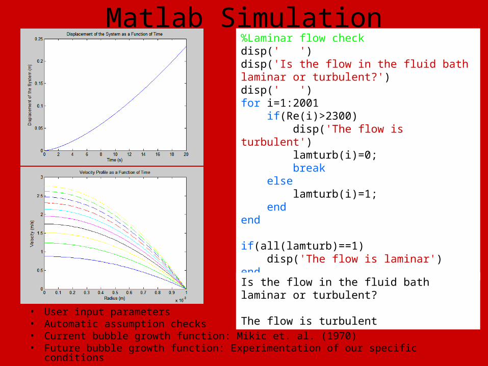
Matlab Simulation
• User input parameters• Automatic assumption checks• Current bubble growth function: Mikic et. al. (1970)• Future bubble growth function: Experimentation of our specific conditions
%Laminar flow checkdisp(' ')disp('Is the flow in the fluid bath laminar or turbulent?')disp(' ')for i=1:2001 if(Re(i)>2300) disp('The flow is turbulent') lamturb(i)=0; break else lamturb(i)=1; endend
if(all(lamturb)==1) disp('The flow is laminar')end
Is the flow in the fluid bath laminar or turbulent? The flow is turbulent

Electrical Circuit Diagram
R d
R L
Power Supply
MeasurementsControl System
P_delivered
P_lost
Heater System
Measurements
0
Filtering (if needed)
0

Control System ConceptsControl System Concept #1 – Analog to Digital Converter (A/D)
.
.
.
A/D Converter
N
2
1
AC PowerSupply
Control System Concept #2 – Pulse Width Modulator (PWM
Pulse Width Modulator
Adjustable Duty Cycle,Voltage Supply,Frequency
DCSupply
AC PowerSupply

Control System Concepts (cont.)Control System Concept #3– Oscillator
OscillatorDC PowerSupply
Fixed amplitude,Duty Cycle;Operable frequency range
Control System Concept #4– Function Generator with Bridging Circuitry
FunctionGenerator
Power Outlet(AC)
BridgingCircuitry
Adjustable Duty Cycle,Amplitude, Frequency
Maintains signals shape,Provides a physical meansto apply signal to Heater

Remainder of quarter
• Derive bubble growth equations
• Finalize design

Questions?