06.06.2005dipac 2005, b.dehning 1 beam loss monitor system for machine protection b. dehning cern...
TRANSCRIPT

06.06.2005 DIPAC 2005, B.Dehning 1
Beam loss monitor system for machine protection
B. DehningCERN AB/BDI

06.06.2005 DIPAC 2005, B.Dehning 2
Beam loss measurement design approach
Damage(system integrity)
Quench(operationalEfficiency)
Scaling:
frequency of events
xconsequence
FailsafeRedundancy
SurveyCheck
Meantime
between failures
Methods:
Stop of next injection
Extraction of beam
Reduction of operational efficiency
Safety ProtectionRisk Availability
SILALARP
Systems:
Beam loss Monitors
Quenchprotection
system
Interlocksystem
¨Dump system
Design issues:
Reliable components
Redundancy, voting
Monitoring of drifts1 10-8 to
1 10-7 1/h

06.06.2005 DIPAC 2005, B.Dehning 3
Damage example and LHC consequences
Tevatron, December 5, 2003 Fast beam loss A Roman Pot moved into beam due to a controls error damaging of 2 collimators and 2 spool pieces
LHC extrapolation Energy in beam 7 times Tevatron Intensity of beam 30 times Tevatron Number of LHC of moving elements in the LHC about 200
How many Magnets and … are damaged?

06.06.2005 DIPAC 2005, B.Dehning 4
Stored beam energies
0.01
0.10
1.00
10.00
100.00
1000.00
1 10 100 1000 10000Momentum [GeV/c]
En
erg
y st
ore
d in
th
e b
eam
[M
J] LHC topenergy
LHC injection(12 SPS batches)
ISR
SNSLEP2
SPS fixed target
HERA
TEVATRON
SPSppbar
SPS batch to LHC
Factor~200
RHIC proton
Damage and Quench threshold to first order identical =>LHC will be exceptional

06.06.2005 DIPAC 2005, B.Dehning 5
LHC Bending Magnet Quench Levels
LHC quench values are lowest
steady state W/cm3Tevatron 7.47E-02RHIC 7.47E-02LHC 5.29E-03
1.E-3
1.E-2
1.E-1
1.E+0
1.E+1
1.E+2
1.E+3
1.E+4
0.01 0.1 1 10 100 1000 10000 100000
loss duration [ms]
W/c
m3
1.E-4
1.E-3
1.E-2
1.E-1
1.E+0
1.E+1
1.E+2
1.E+3
Gy/
s
Quench Power 7 Tev
Quench Power 450 GeV
(values proportional)
13 us J/cm3Tevatron 4.50E-03RHIC 1.80E-02LHC 8.70E-04
DESY 2.6 – 6.6 E-03

06.06.2005 DIPAC 2005, B.Dehning 6
Quench Levels and Energy Dependence
Fast decrease of quench levels between 0.45 to 2 TeV Similar behaviour expected for damage levels

06.06.2005 DIPAC 2005, B.Dehning 7
Failure rate and checks
Systems parallel + survey + check:
1. in case of system failure dump beam (failsafe)
2. verification of functionality: simulate measurement and
comparison with expected result
0.00000001
0.0000001
0.000001
0.00001
0.0001
0.001
0.01
0 50 100 150 200 250 300
time [a.u.]
failu
re r
ate
[a
. u.]
constant f. r.
systems parallel
systems parallel + surv.
systems parallel + surv. + check
06.06.2005 DIPAC 2005, B.Dehning 8
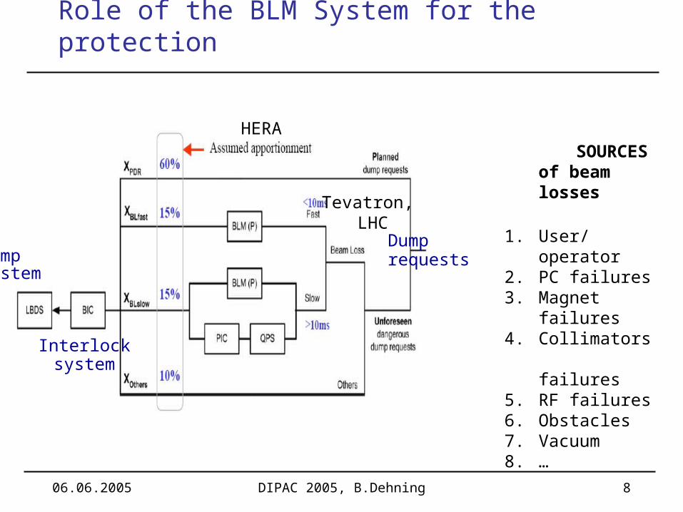
Role of the BLM System for the protection
SOURCES of beam losses
1. User/operator2. PC failures3. Magnet failures4. Collimators
failures5. RF failures6. Obstacles7. Vacuum8. …
HERA
Tevatron, LHC
Dumpsystem
Interlocksystem
Dumprequests

06.06.2005 DIPAC 2005, B.Dehning 9
Beam loss measurement system layouts
FNAL
LHC
Examples from:
SNS, LHC FNALLHC LHC

06.06.2005 DIPAC 2005, B.Dehning 10
Ionisation chamber SNS
Stainless steal Coaxial design, 3 cylinder
(outside for shielding) Low pass filter at the HV
input
Ar, N2 gas filling at 100
mbar over pressure Outer inner electrode
diameter 1.9 / 1.3 cm Length 40 cm Sensitive volume 0.1 l Voltage 2k V Ion collection time 72 us

06.06.2005 DIPAC 2005, B.Dehning 11
Ionisation chamber LHC
Stainless steal cylinder Parallel electrodes separated by
0.5 cm Al electrodes Low pass filter at the HV input
N2 gas filling at 100 mbar over
pressure Diameter 8.9 cm Length 60 cm Sensitive volume 1.5 l Voltage 1.5 kV Ion collection time 85 us

06.06.2005 DIPAC 2005, B.Dehning 12
Ionisation chamber measurements
Energy deposition (LHC)
Beam
scanned
Signal vs voltage (SNS)

06.06.2005 DIPAC 2005, B.Dehning 13
Ionisation chamber currents (1 litre, LHC)
450 GeV, quench levels (min)
100 s 12.5 nA
7 TeV, quench levels (min)
100 s 2 nA
Required 25 % rel. accuracy, error small against 25% => 5 %
100 pA
450 GeV, dynamic range min., used for tuning
10 s 10 pA
100 s 2.5 pA
7 TeV, dynamic range min.
10 s 160 pA
100s 80 pA

06.06.2005 DIPAC 2005, B.Dehning 14
Gain Variation of SPS Chambers
30 years of operation Measurements done with
installed electronic Relative accuracy
< 0.01 (for ring BLMs) < 0.05 (for Extr., inj.
BLMs) Gain variation only observed
in high radiation areas Consequences for LHC:
No gain variation expected in the straight section and ARC of LHC
Variation of gain in collimation possible for ionisation chambers
SPS BLMs
02468
101214161820
36 42 48 54 60 66M
ore
current [pA]
Fre
qu
en
cy
dis
trib
uti
on
0
20
40
60
80
100
120
140
160
Extr., inj. BLMs
Ring BLMs
Test with Cs137
Total received dose: ring 0.1 to 1 kGy/yearextr 0.1 to 10 MGy/year
06.06.2005 DIPAC 2005, B.Dehning 15
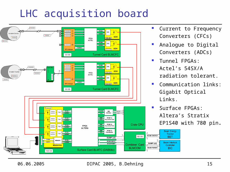
LHC acquisition board Current to Frequency
Converters (CFCs) Analogue to Digital
Converters (ADCs) Tunnel FPGAs:
Actel’s 54SX/A radiation tolerant.
Communication links:Gigabit Optical Links.
Surface FPGAs: Altera’s Stratix EP1S40 with 780 pin.

06.06.2005 DIPAC 2005, B.Dehning 16
LHC tunnel card Not very complicated design “simple” Large Dynamic Range (8 orders)
Current-to-Frequency Converter (CFC) Analogue-to-Digital Converter
Radiation tolerant (500 Gy, 1 107 p/s/cm2) Bipolar Customs ASICs Triple module redundancy
Reset time Integration time
V out
I +I -
ThresholdComparator
100 ns 100 ns to 100 s

06.06.2005 DIPAC 2005, B.Dehning 17
FNAL beam loss integrator and digitizer
Independent operation form crate CPU (FNAL, LHC)
Thresholds managed by control card over control bus (LHC combined)
VMEControl bus
Control bus
FNAL LHC
channels 4 16
Time resolution
21 s 40 s
# of running sums
3 11
windows 21 s to 1.4 s
80 s to 84 s
thresholds 4 12
Synchronized to machine timing
yes no
post mortem buffer
4k values
1k values

06.06.2005 DIPAC 2005, B.Dehning 18
FNAL abort concentrator
Measurements and threshold are compared every 21 s (fastest) (LHC 80 s)
Channels can be masked (LHC yes)
Aborts of particular type are counted and compared to the required multiplicity value for this type (LHC: single channel will trigger abort, channel can be masked depending on beam condition)
Ring wide concentration possible (LHC no)

06.06.2005 DIPAC 2005, B.Dehning 19
Beam loss measurement design approach
Damage(system integrity)
Quench(operationalEfficiency)
Scaling:
frequency of events
xconsequence
FailsafeRedundancy
SurveyCheck
Meantime
between failures
Methods:
Stop of next injection
Extraction of beam
Reduction of operational efficiency
Safety ProtectionRisk Availability
SILALARP
Systems:
Beam loss Monitors
Quenchprotection
system
Interlocksystem
¨Dump system
Design issues:
Reliable components
Redundancy, voting
Monitoring of drifts1 10-8 to
1 10-7 1/h

06.06.2005 DIPAC 2005, B.Dehning 20
Test Procedure of Analog Signal Chain
Basic concept: Automatic test measurements in between two fills
Measurement of dark current Modulation of high voltage supply of chambers
Check of components in Ionisation chamber (R, C) Check of capacity of chamber (insulation) Check of cabling Check of stable signal between few pA to some nA (quench level
region)
Not checked: gas gain of chamber (only once a year with source)
06.06.2005 DIPAC 2005, B.Dehning 21
CompareCRCs
Secondary B Signal(256 bits)
S/W & TTLoutput
Check CRCvalidity
DeMux
1 2 3 … 8
Truncateextra/redundant bits
(leave 160 bits)
Status10-bits
Primary A Signal (256 bits)
Only CRC
(4 byte)
Only CRC
(4 byte)
Signal Select(A or B)
ErrorError
Error
Error
Check CRCvalidity
Error
Reception______________ _ _
Tx Check&Signal Choice
______________ _ _
Tunnel Status Check______________ _ _
Format Data
______________ _ _
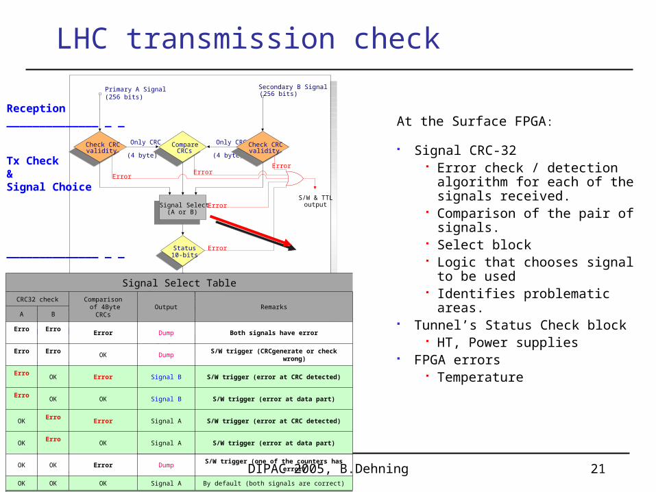
LHC transmission check
Signal Select Table
CRC32 check Comparison of 4Byte
CRCsOutput Remarks
A B
Error Error Error Dump Both signals have error
Error Error OK DumpS/W trigger (CRCgenerate or check
wrong)
Error OK Error Signal B S/W trigger (error at CRC detected)
Error OK OK Signal B S/W trigger (error at data part)
OK Error Error Signal A S/W trigger (error at CRC detected)
OK Error OK Signal A S/W trigger (error at data part)
OK OK Error DumpS/W trigger (one of the counters has
error)
OK OK OK Signal A By default (both signals are correct)
At the Surface FPGA:
Signal CRC-32 Error check / detection
algorithm for each of the signals received.
Comparison of the pair of signals.
Select block Logic that chooses signal to
be used Identifies problematic areas.
Tunnel’s Status Check block HT, Power supplies
FPGA errors Temperature

06.06.2005 DIPAC 2005, B.Dehning 22
Reliability Study (LHC)
False dumps per year
0%
10%
20%
30%
40%
jfet switch Power Supply monostable comparator integrator other
Lea
kag
e
General failure
Bre
akd
ow
n
Open
General
failure
Signal variation
Arc
Shorted input
Str
aig
ht
sect
ion
Open input
by G. Guaglio
Apportionment of yearly damage probability
0%
10%
20%
30%
40%
50%
Ion. Chamber Ion.C. cable Surface BLMTC Tunnel BLMCFC
Resistor shorted
Wrong energy signal?
Resistor increased
Capacitor decreased
Wire shorted changes
Solder joints
Mechanical divers
Insulation
Gas pressure
Dump switch
Memories
C open
Comparator
Integrator
Relative probability of a system component being responsible for a damage to an LHC magnet in the case of a loss.
Relative probability of a BLM component generating a false dump.
Most false dumps initiated by analog front end (98%) because:
1. Reduced check2. Quantity3. Harsh environment
Highest damage probability given by the Ionisation chamber (80%) because:
1. Reduced checks
2. Harsh environment

06.06.2005 DIPAC 2005, B.Dehning 23
Beam Loss Display
0
0.2
0.4
0.6
0.8
1
1.2
Mea
sure
d / T
hres
hold
Det
ecto
r 1
Det
ecto
r 2
Det
ecto
r 3
Det
ecto
r 4
Det
ecto
r 5
Det
ecto
r 6
. . .
Det
ecto
r40
00
R1
R2
R3
R4
R5
R6
War
ning
Dum
p
Inte
grat
ion
Tim
e In
terv
als

06.06.2005 DIPAC 2005, B.Dehning 24
Literature
SNS, Ion chamber, R.C. Witkover, BIW02 FNAL, BLM electronics, J.D. Lewis et al., IEEE 04 http://ab-div-bdi-bl-blm.web.cern.ch/ab-div-bdi-
bl-blm LHC
Reliability issues, G. Guaglio et al., BIW04, R. Filippini et al., PAC 05
Front end electronics, analog, thesis, W. Friesenbichler Digital signal transmission, thesis, R. Leitner Digital signal treatment, C. Zamantzas, this workshop

06.06.2005 DIPAC 2005, B.Dehning 25
Reserve slides

06.06.2005 DIPAC 2005, B.Dehning 26
Approximation of Quench Levels (LHC)
Dump level tables are loaded in a non volatile RAM Any curve approximation possible
Loss durations Energy dependence
Avarage approximation
1.E-10
1.E-09
1.E-08
1.E-07
1.E-06
1.E-05
1.E-04
1.E-03
1.E-02
0.01 0.1 1 10 100 1000 10000 100000 1000000
loss duration [ms]
Arc
cha
mbe
r cu
rren
t (1
litr
e) [
A]
7 TeV high 450 GeV lowApproximation Approximation
1.E-05
1.E-04
1 10 100
Relative error kept < 20 %
06.06.2005 DIPAC 2005, B.Dehning 27
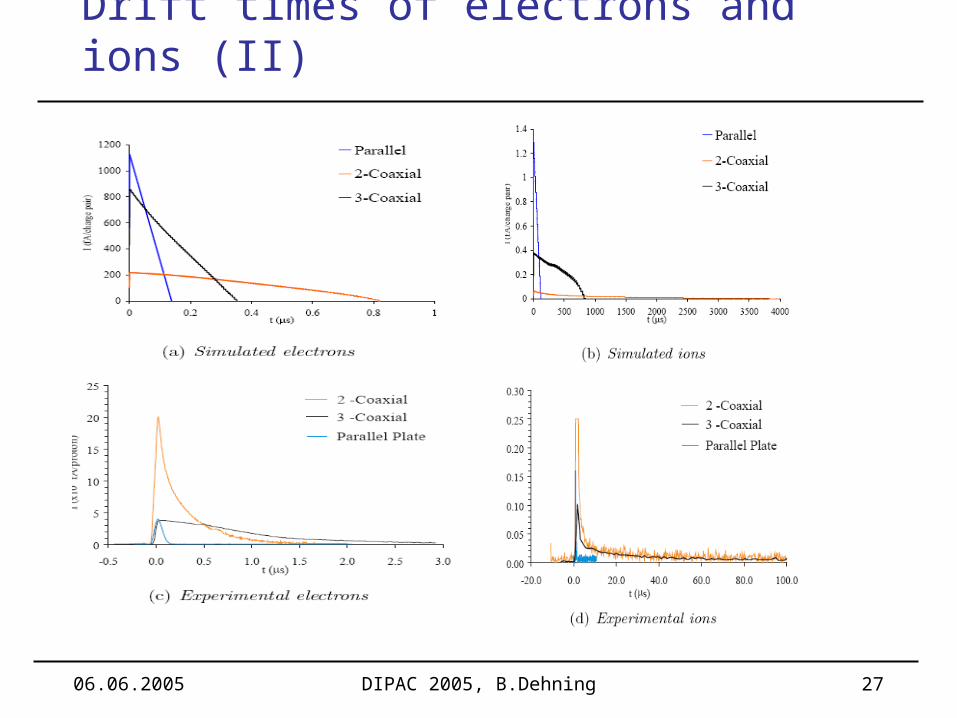
Drift times of electrons and ions (II)

06.06.2005 DIPAC 2005, B.Dehning 28
Drift times of electrons and ions (I)

06.06.2005 DIPAC 2005, B.Dehning 29
Response of ion chambers for different particle species
u+
u-
Gam
ma
e+
e-
pi+
pi-
neutr
on
pro
ton
Due to attenuation ofshower => increase of non linearity of chamber response
06.06.2005 DIPAC 2005, B.Dehning 30
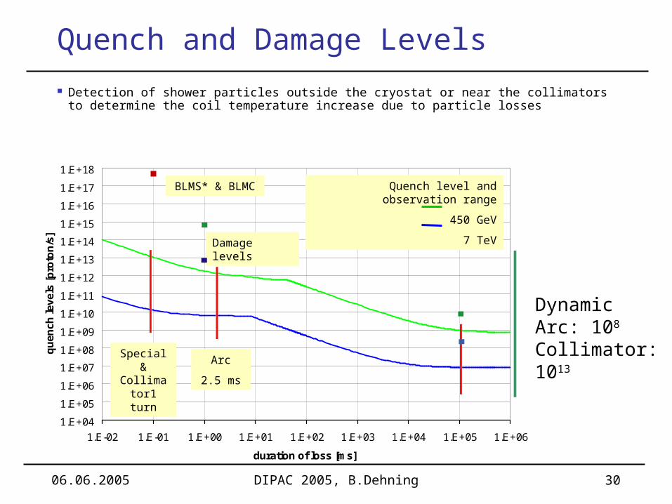
Quench and Damage Levels
Detection of shower particles outside the cryostat or near the collimators to determine the coil temperature increase due to particle losses
1.E+04
1.E+05
1.E+06
1.E+07
1.E+08
1.E+09
1.E+10
1.E+11
1.E+12
1.E+13
1.E+14
1.E+15
1.E+16
1.E+17
1.E+18
1.E-02 1.E-01 1.E+00 1.E+01 1.E+02 1.E+03 1.E+04 1.E+05 1.E+06
duration of loss [ms]
qu
ench
leve
ls [
pro
ton
/s]
Quench level and observation range
450 GeV
7 TeV
DynamicArc: 108
Collimator: 1013
Damage levels
Arc
2.5 ms
Special & Collimator
1 turn
BLMS* & BLMC
06.06.2005 DIPAC 2005, B.Dehning 31
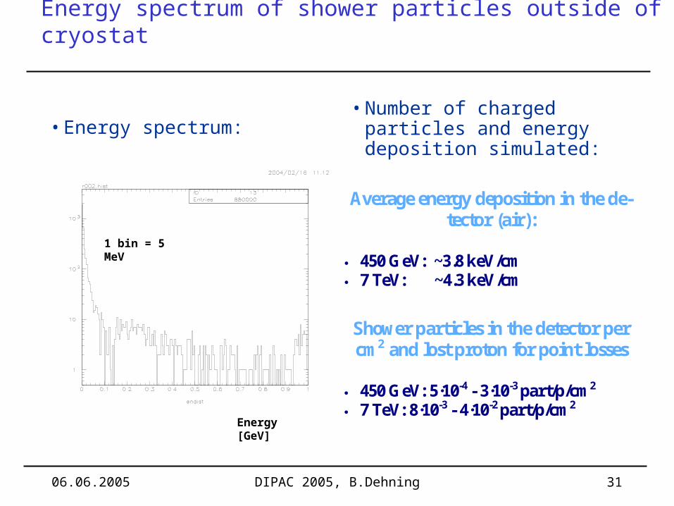
Energy spectrum of shower particles outside of cryostat
Energy [GeV]
1 bin = 5 MeV
• Energy spectrum:
Average energy deposition in the de-tector (air):
450 GeV: ~3.8 keV/cm 7 TeV: ~4.3 keV/cm
Shower particles in the detector per cm2 and lost proton for point losses
450 GeV: 5·10-4 - 3·10-3 part/p/cm2 7 TeV: 8·10-3 - 4·10-2 part/p/cm2
• Number of charged particles and energy deposition simulated:

06.06.2005 DIPAC 2005, B.Dehning 32
Ionisation Chamber Time Response Measurements (BOOSTER)
Chamber beam response Chamber current vs beam current
Intensity discrepancy by a factor two
Intensity density: - Booster 6 109 prot./cm2, two orders larger as in LHC
FWHMe-= 150 ns
length proton= 50 ns
80 % of signalin one turn

06.06.2005 DIPAC 2005, B.Dehning 33
Current to Frequency Converter and Radiation
Variation at the very low end of the dynamic range Insignificant variations at quench levels
CFC2-TOTAL-0Gy-1000Gy
1.0E-01
1.0E+00
1.0E+01
1.0E+02
1.0E+03
1.0E+04
1.0E+05
1.0E+06
1.0E+07
1.E-11 1.E-10 1.E-09 1.E-08 1.E-07 1.E-06 1.E-05 1.E-04 1.E-03
I in [A]
f o
ut
[Hz]
Ch2-CFC2-not-irr-1meas.Ch2-CFC2-not-irr-2meas.Ch2-CFC2-JFET-0GyCh2-CFC2-JFET-500GyCh2-CFC2-JFET-1000GyCh8-CFC2-not-irr-1meas.Ch8-CFC2-not-irr-2meas.Ch8-CFC2-JFETS-0GyCh8-CFC2-JFETS-300GyCh8-CFC2-JFETS-600GyCh4-CFC2-not-irr-1meas.Ch4-CFC2-not-irr-2meas.Ch4-CFC2-JFETS-0GyCh4-CFC2-JFETS-300GyCh4-CFC2-JFETS-600GyCh6-CFC2-not-irr-1meas.Ch6-CFC2-not-irr-2meas.Ch6-CFC2-JFETS-0GyCh6-CFC2-JFETS-300GyCh6-CFC2-JFETS-600GyCh8-CFC2-not-irr-1meas.Ch8-CFC2-not-irr-2meas.Ch8-CFC2-TOTAL-300GyCh8-not-irr-1meas.Ch8-not-irr-2meas.Ch7-not-irr-1meas.Ch7-not-irr-2meas.Ch5-not-irr-1meas.Ch5-not-irr-2meas.Ch3-not-irr-1meas.Ch3-not-irr-2meas.Ch1-not-irr-1meas.Ch1-not-irr-2meas.Ch1-CFC2-JFET-0Gy-not-irrCh1-CFC2-JFET-500Gy-not-irrCh1-CFC2-JFET-1000Gy-not-irrCh1-CFC2-JFETS-0Gy-not-irrCh1-CFC2-JFETS-300Gy-not-irrCh1-CFC2-JFETS-600Gy-not-irrCh1-CFC2-TOTA-300Gy-not-irr
Ch8-CFC2-TOTAL-0Gy-300Gy
1.0E-01
1.0E+00
1.0E+01
1.0E+02
1.0E+03
1.0E+04
1.E-11 1.E-10 1.E-09 1.E-08 1.E-07 1.E-06I in [A]
f o
ut
[Hz]
Ch8-CFC2-not-irr-1meas.Ch8-CFC2-not-irr-2meas.Ch8-CFC2-TOTAL-300Gy
Quench 7 TeV
Quench 7 TeV