05obd systemh(pzev&lev2) mod - star … extra info...obd-ii information summary sheet fuji heavy...
TRANSCRIPT
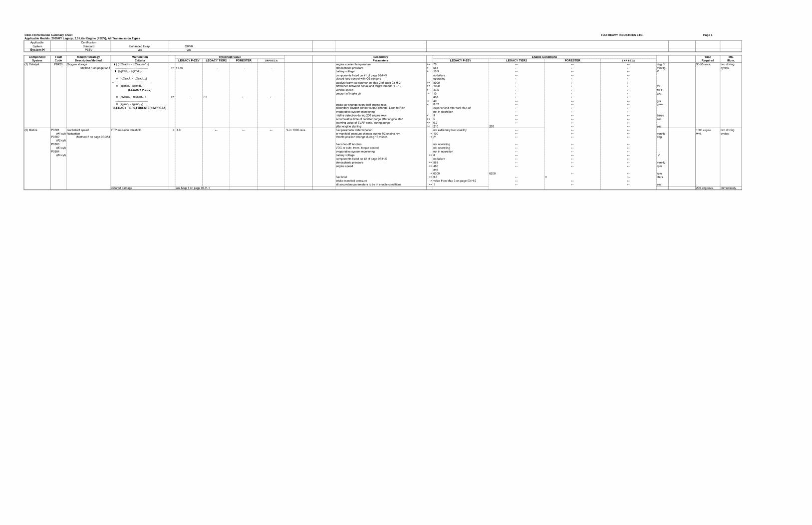
OBD-II Information Summary Sheet FUJI HEAVY INDUSTRIES LTD. Page 1Applicable Models: 2005MY Legacy; 2.5 Liter Engine (PZEV); All Transmission Types
Applicable CertificationSystem Standard Enhanced Evap. ORVR
System H PZEV yes yes
Component/ Fault Monitor Strategy Malfunction Secondary Time MILSystem Code Description/Method Criteria LEGACY P-ZEV LEGACY TIER2 FORESTER IMPREZA Parameters LEGACY P-ZEV LEGACY TIER2 FORESTER IMPREZA Required Illum.
(1) Catalyst P0420 Oxygen storage � | (ro2sadrn - ro2sadrn-1) | engine coolant temperature >= 70 ← ← ← deg C 30-55 secs. two driving/Method 1 on page 02-1 ---------------------------------- >= 11.16 - - - atmospheric pressure > 563 ← ← ← mmHg cycles
� (sglmdrn - sglmdrn-1) battery voltage > 10.9 ← ← ← Vcomponents listed on #1 of page 03-H-5 no failure ← ← ←
� (ro2sadln - ro2sadln-1) closed loop control with O2 sensors operating ← ← ← + ---------------------------------- catalyst warm-up counter on Map 2 of page 03-H-2 >= 8000 ← ← ← � (sglmdln - sglmdln-1) difference between actual and target lambda < 0.10 >= 1000 ← ← ← ms
(LEGACY P-ZEV) vehicle speed > 43.5 ← ← ← MPHamount of intake air >= 10 ← ← ← g/s
� (ro2sadn - ro2sadn-1) >= - 7.5 ← ← and ← ← ← ---------------------------------- < 40 ← ← ← g/s � (sglmdn - sglmdn-1) intake air change every half engine revs. < 0.02 ← ← ← g/rev
(LEGACY TIER2,FORESTER,IMPREZA) secondary oxygen sensor output change, Lean to Rich experienced after fuel shut-off ← ← ←evaporative system monitoring not in operation ← ← ←misfire detection during 200 engine revs. < 5 ← ← ← timesaccumulative time of canister purge after engine start >= 5 ← ← ← seclearning value of EVAP conc. during purge <= 0.2 ← ← ←after engine starting >= 210 205 ← ← sec
(2) Misfire P0301 crankshaft speed FTP emission threshold > 1.0 ← ← ← % in 1000 revs. fuel parameter determination not extremely low volatility ← ← ← 1000 engine two driving(#1 cyl) fluctuation in-manifold pressure change during 1/2 engine rev. < 100 ← ← ← mmHg revs. cycles
P0302 /Method 2 on page 02-3&4 throttle position change during 16 msecs. < 21 ← ← ← deg.(#2 cyl)
P0303 fuel shut-off function not operating ← ← ←(#3 cyl) VDC or auto. trans. torque control not operating ← ← ←
P0304 evaporative system monitoring not in operation ← ← ←(#4 cyl) battery voltage >= 8 ← ← ← V
components listed on #2 of page 03-H-5 no failure ← ← ←atmospheric pressure >= 563 ← ← ← mmHgengine speed >= 460 ← ← ← rpm
and< 6300 6200 ← ← rpm
fuel level >= 9.6 ← 9 <-- litersintake manifold pressure > value from Map 3 on page 03-H-2 ← ← ←all secondary parameters to be in enable conditions >= 1 ← ← ← sec
catalyst damage see Map 1 on page 03-H-1 200 eng.revs. immediately
Threshold Value Enable Conditions
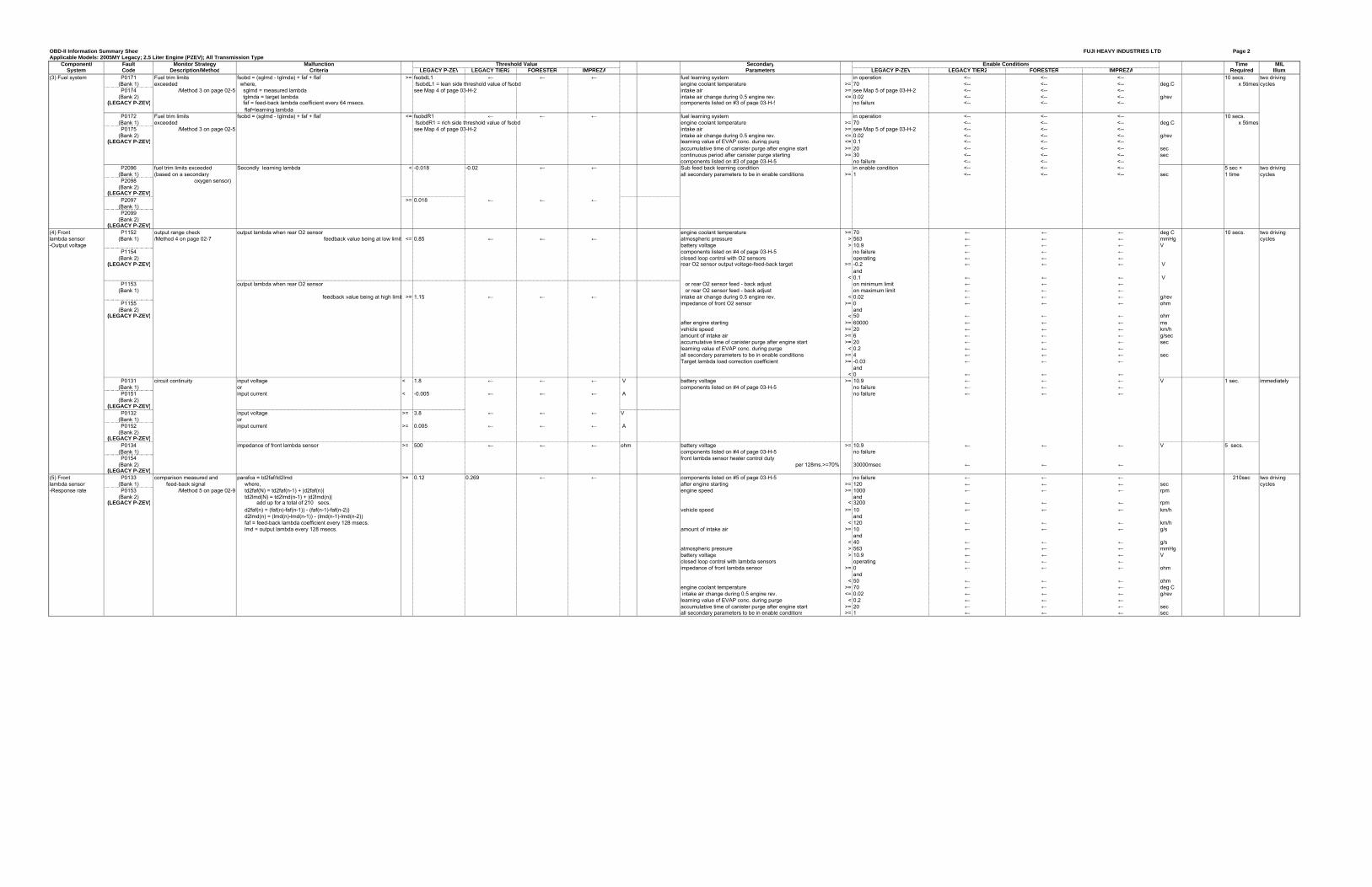
OBD-II Information Summary Sheet FUJI HEAVY INDUSTRIES LTD Page 2Applicable Models: 2005MY Legacy; 2.5 Liter Engine (PZEV); All Transmission Types
Component/ Fault Monitor Strategy Malfunction Secondary Time MILSystem Code Description/Method Criteria LEGACY P-ZEV LEGACY TIER2 FORESTER IMPREZA Parameters LEGACY P-ZEV LEGACY TIER2 FORESTER IMPREZA Required Illum.
(3) Fuel system P0171 Fuel trim limits fsobd = (sglmd - tglmda) + faf + flaf >= fsobdL1 ← ← ← fuel learning system in operation <-- <-- <-- 10 secs. two driving(Bank 1) exceeded where, fsobdL1 = lean side threshold value of fsobd engine coolant temperature >= 70 <-- <-- <-- deg.C x 5times cyclesP0174 /Method 3 on page 02-5 sglmd = measured lambda see Map 4 of page 03-H-2 intake air >= see Map 5 of page 03-H-2 <-- <-- <--
(Bank 2) tglmda = target lambda intake air change during 0.5 engine rev. <= 0.02 <-- <-- <-- g/rev(LEGACY P-ZEV) faf = feed-back lambda coefficient every 64 msecs. components listed on #3 of page 03-H-5 no failure <-- <-- <--
flaf=learning lambdaP0172 Fuel trim limits fsobd = (sglmd - tglmda) + faf + flaf <= fsobdR1 ← ← ← fuel learning system in operation <-- <-- <-- 10 secs.
(Bank 1) exceeded fsobdR1 = rich side threshold value of fsobd engine coolant temperature >= 70 <-- <-- <-- deg.C x 5timesP0175 /Method 3 on page 02-5 see Map 4 of page 03-H-2 intake air >= see Map 5 of page 03-H-2 <-- <-- <--
(Bank 2) intake air change during 0.5 engine rev. <= 0.02 <-- <-- <-- g/rev(LEGACY P-ZEV) learning value of EVAP conc. during purge <= 0.1 <-- <-- <--
accumulative time of canister purge after engine start >= 20 <-- <-- <-- seccontinuous period after canister purge starting >= 30 <-- <-- <-- seccomponents listed on #3 of page 03-H-5 no failure <-- <-- <--
P2096 fuel trim limits exceeded Secondly learning lambda < -0.018 -0.02 ← ← Sub feed back learning condition in enable condition <-- <-- <-- 5 sec × two driving(Bank 1) (based on a secondary all secondary parameters to be in enable conditions >= 1 <-- <-- <-- sec 1 time cyclesP2098 oxygen sensor)
(Bank 2)(LEGACY P-ZEV)
P2097 >= 0.018 ← ← ←(Bank 1)P2099
(Bank 2)(LEGACY P-ZEV)
(4) Front P1152 output range check output lambda when rear O2 sensor engine coolant temperature >= 70 ← ← ← deg C 10 secs. two drivinglambda sensor (Bank 1) /Method 4 on page 02-7 feedback value being at low limit <= 0.85 ← ← ← atmospheric pressure > 563 ← ← ← mmHg cycles-Output voltage battery voltage > 10.9 ← ← ← V
P1154 components listed on #4 of page 03-H-5 no failure ← ← ←(Bank 2) closed loop control with O2 sensors operating ← ← ←
(LEGACY P-ZEV) rear O2 sensor output voltage-feed-back target >= -0.2 ← ← ← V and
< 0.1 ← ← ← VP1153 output lambda when rear O2 sensor or rear O2 sensor feed - back adjust on minimum limit ← ← ←
(Bank 1) or rear O2 sensor feed - back adjust on maximum limit ← ← ←feedback value being at high limit >= 1.15 ← ← ← intake air change during 0.5 engine rev. < 0.02 ← ← ← g/rev
P1155 impedance of front O2 sensor >= 0 ← ← ← ohm(Bank 2) and
(LEGACY P-ZEV) < 50 ← ← ← ohmafter engine starting >= 60000 ← ← ← msvehicle speed >= 20 ← ← ← km/hamount of intake air >= 6 ← ← ← g/secaccumulative time of canister purge after engine start >= 20 ← ← ← seclearning value of EVAP conc. during purge < 0.2 ← ← ←all secondary parameters to be in enable conditions >= 4 ← ← ← secTarget lambda load correction coefficient >= -0.03 ← ← ←
and< 0 ← ← ←
P0131 circuit continuity input voltage < 1.8 ← ← ← V battery voltage >= 10.9 ← ← ← V 1 sec. immediately(Bank 1) or components listed on #4 of page 03-H-5 no failure ← ← ←P0151 input current < -0.005 ← ← ← A no failure ← ← ←
(Bank 2)(LEGACY P-ZEV)
P0132 input voltage >= 3.8 ← ← ← V(Bank 1) orP0152 input current >= 0.005 ← ← ← A
(Bank 2)(LEGACY P-ZEV)
P0134 impedance of front lambda sensor >= 500 ← ← ← ohm battery voltage >= 10.9 ← ← ← V 5 secs.(Bank 1) components listed on #4 of page 03-H-5 no failureP0154 front lambda sensor heater control duty
(Bank 2) per 128ms.>=70% 30000msec ← ← ←(LEGACY P-ZEV)
(5) Front P0133 comparison measured and parafca = td2faf/td2lmd >= 0.12 0.269 ← ← components listed on #5 of page 03-H-5 no failure ← ← ← 210sec two drivinglambda sensor (Bank 1) feed-back signal where, after engine starting >= 120 ← ← ← sec cycles-Response rate P0153 /Method 5 on page 02-9 td2faf(N) = td2faf(n-1) + |d2faf(n)| engine speed >= 1000 ← ← ← rpm
(Bank 2) td2lmd(N) = td2lmd(n-1) + |d2lmd(n)| and(LEGACY P-ZEV) add up for a total of 210 secs. < 3200 ← ← ← rpm
d2faf(n) = (faf(n)-faf(n-1)) - (faf(n-1)-faf(n-2)) vehicle speed >= 10 ← ← ← km/h d2lmd(n) = (lmd(n)-lmd(n-1)) - (lmd(n-1)-lmd(n-2)) and faf = feed-back lambda coefficient every 128 msecs. < 120 ← ← ← km/h lmd = output lambda every 128 msecs. amount of intake air >= 10 ← ← ← g/s
and< 40 ← ← ← g/s
atmospheric pressure > 563 ← ← ← mmHgbattery voltage > 10.9 ← ← ← Vclosed loop control with lambda sensors operating ← ← ←impedance of front lambda sensor >= 0 ← ← ← ohm
and< 50 ← ← ← ohm
engine coolant temperature >= 70 ← ← ← deg C intake air change during 0.5 engine rev. <= 0.02 ← ← ← g/rev learning value of EVAP conc. during purge < 0.2 ← ← ←accumulative time of canister purge after engine start >= 20 ← ← ← secall secondary parameters to be in enable conditions >= 1 ← ← ← sec
Threshold Value Enable Conditions
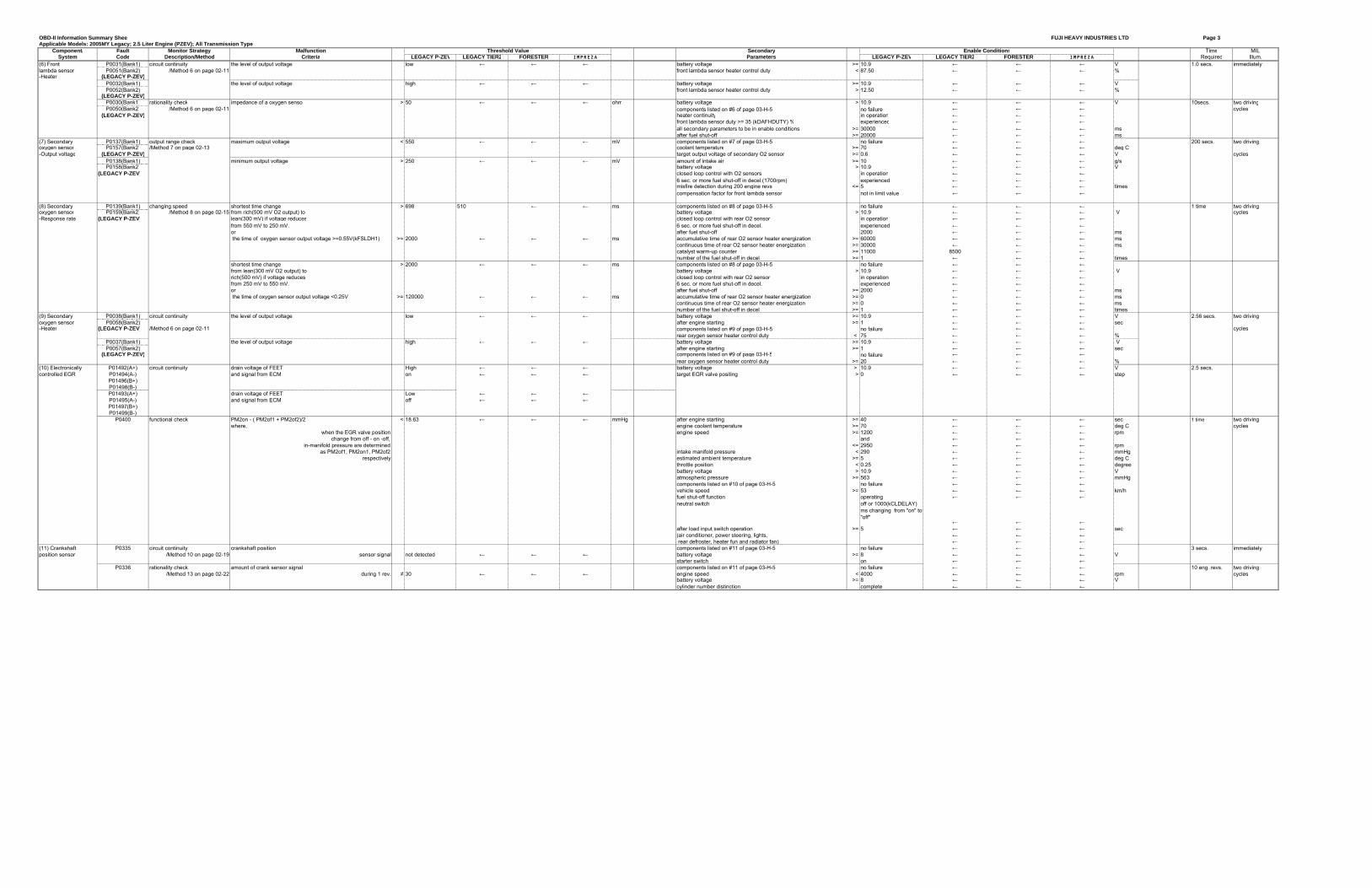
OBD-II Information Summary Sheet FUJI HEAVY INDUSTRIES LTD Page 3Applicable Models: 2005MY Legacy; 2.5 Liter Engine (PZEV); All Transmission Types
Component/ Fault Monitor Strategy Malfunction Secondary Time MILSystem Code Description/Method Criteria LEGACY P-ZEV LEGACY TIER2 FORESTER IMPREZA Parameters LEGACY P-ZEV LEGACY TIER2 FORESTER IMPREZA Required Illum.
(6) Front P0031(Bank1) circuit continuity the level of output voltage low ← ← ← battery voltage >= 10.9 ← ← ← V 1.0 secs. immediatelylambda sensor P0051(Bank2) /Method 6 on page 02-11 front lambda sensor heater control duty < 87.50 ← ← ← %-Heater (LEGACY P-ZEV)
P0032(Bank1) the level of output voltage high ← ← ← battery voltage >= 10.9 ← ← ← VP0052(Bank2) front lambda sensor heater control duty > 12.50 ← ← ← %
(LEGACY P-ZEV)P0030(Bank1) rationality check impedance of a oxygen sensor > 50 ← ← ← ohm battery voltage > 10.9 ← ← ← V 10secs. two drivingP0050(Bank2) /Method 6 on page 02-11 components listed on #6 of page 03-H-5 no failure ← ← ← cycles
(LEGACY P-ZEV) heater continuity in operation ← ← ←front lambda sensor duty >= 35 (kDAFHDUTY) % experienced ← ← ←all secondary parameters to be in enable conditions >= 30000 ← ← ← msafter fuel shut-off >= 20000 ← ← ← ms
(7) Secondary P0137(Bank1) output range check maximum output voltage < 550 ← ← ← mV components listed on #7 of page 03-H-5 no failure ← ← ← 200 secs. two drivingoxygen sensor P0157(Bank2) /Method 7 on page 02-13 coolant temperature >= 70 ← ← ← deg C-Output voltage (LEGACY P-ZEV) target output voltage of secondary O2 sensor >= 0.6 ← ← ← V cycles
P0138(Bank1) minimum output voltage > 250 ← ← ← mV amount of intake air >= 10 ← ← ← g/sP0158(Bank2) battery voltage > 10.9 ← ← ← V
(LEGACY P-ZEV) closed loop control with O2 sensors in operation ← ← ←6 sec. or more fuel shut-off in decel.(1700rpm) experienced ← ← ←misfire detection during 200 engine revs <= 5 ← ← ← timescompensation factor for front lambda sensor not in limit value ← ← ←
(8) Secondary P0139(Bank1) changing speed shortest time change > 698 510 ← ← ms components listed on #8 of page 03-H-5 no failure ← ← ← 1 time two drivingoxygen sensor P0159(Bank2) /Method 8 on page 02-15 from rich(500 mV O2 output) to battery voltage > 10.9 ← ← ← V cycles-Response rate (LEGACY P-ZEV) lean(300 mV) if voltage reduces closed loop control with rear O2 sensor in operation ← ← ←
from 550 mV to 250 mV. 6 sec. or more fuel shut-off in decel. experienced ← ← ←or after fuel shut-off 2000 ← ← ← ms the time of oxygen sensor output voltage >=0.55V(kFSLDH1) >= 2000 ← ← ← ms accumulative time of rear O2 sensor heater energization >= 60000 ← ← ← ms
continuous time of rear O2 sensor heater energization >= 30000 ← ← ← mscatalyst warm-up counter >= 11000 8500 ← ←number of the fuel shut-off in decel >= 1 ← ← ← times
shortest time change > 2000 ← ← ← ms components listed on #8 of page 03-H-5 no failure ← ← ←from lean(300 mV O2 output) to battery voltage > 10.9 ← ← ← Vrich(500 mV) if voltage reduces closed loop control with rear O2 sensor in operation ← ← ←from 250 mV to 550 mV. 6 sec. or more fuel shut-off in decel. experienced ← ← ←or after fuel shut-off >= 2000 ← ← ← ms the time of oxygen sensor output voltage <0.25V >= 120000 ← ← ← ms accumulative time of rear O2 sensor heater energization >= 0 ← ← ← ms
continuous time of rear O2 sensor heater energization >= 0 ← ← ← msnumber of the fuel shut-off in decel >= 1 ← ← ← times
(9) Secondary P0038(Bank1) circuit continuity the level of output voltage low ← ← ← battery voltage >= 10.9 ← ← ← V 2.56 secs. two drivingoxygen sensor P0058(Bank2) after engine starting >= 1 ← ← ← sec-Heater (LEGACY P-ZEV) /Method 6 on page 02-11 components listed on #9 of page 03-H-5 no failure ← ← ← cycles
rear oxygen sensor heater control duty < 75 ← ← ← %P0037(Bank1) the level of output voltage high ← ← ← battery voltage >= 10.9 ← ← ← VP0057(Bank2) after engine starting >= 1 ← ← ← sec
(LEGACY P-ZEV) components listed on #9 of page 03-H-5 no failure ← ← ←rear oxygen sensor heater control duty >= 20 ← ← ← %
(10) Electronically P01492(A+) circuit continuity drain voltage of FEET High ← ← ← battery voltage > 10.9 ← ← ← V 2.5 secs.controlled EGR P01494(A-) and signal from ECM on ← ← ← target EGR valve positing > 0 ← ← ← step
P01496(B+)P01498(B-)P01493(A+) drain voltage of FEET Low ← ← ←P01495(A-) and signal from ECM off ← ← ←P01497(B+)P01499(B-)
P0400 functional check PM2on - ( PM2of1 + PM2of2)/2 < 18.63 ← ← ← mmHg after engine starting >= 40 ← ← ← sec 1 time two drivingwhere, engine coolant temperature >= 70 ← ← ← deg C cycles
when the EGR valve position engine speed >= 1200 ← ← ← rpm change from off - on -off, and ← ← ←
in-manifold pressure are determined <= 2950 ← ← ← rpmas PM2of1, PM2on1, PM2of2 intake manifold pressure < 290 ← ← ← mmHg
respectively estimated ambient temperature >= 5 ← ← ← deg Cthrottle position < 0.25 ← ← ← degreebattery voltage > 10.9 ← ← ← Vatmospheric pressure >= 563 ← ← ← mmHgcomponents listed on #10 of page 03-H-5 no failure ← ← ←vehicle speed >= 53 ← ← ← km/hfuel shut-off function operating ← ← ←neutral switch off or 1000(kCLDELAY)
ms changing from "on" to "off"
← ← ←after load input switch operation >= 5 ← ← ← sec(air conditioner, power steering, lights, ← ← ← rear defroster, heater fun and radiator fan) ← ← ←
(11) Crankshaft P0335 circuit continuity crankshaft position components listed on #11 of page 03-H-5 no failure ← ← ← 3 secs. immediatelyposition sensor /Method 10 on page 02-19 sensor signal not detected ← ← ← battery voltage >= 8 ← ← ← V
starter switch on ← ← ←P0336 rationality check amount of crank sensor signal components listed on #11 of page 03-H-5 no failure ← ← ← 10 eng. revs. two driving
/Method 13 on page 02-22 during 1 rev. ≠ 30 ← ← ← engine speed < 4000 ← ← ← rpm cyclesbattery voltage >= 8 ← ← ← Vcylinder number distinction complete ← ← ←
Threshold Value Enable Conditions
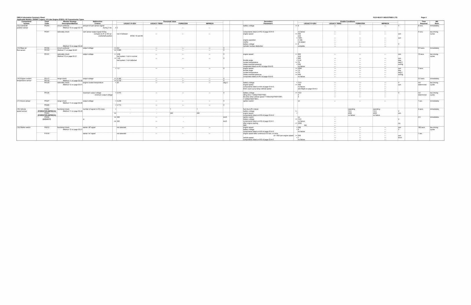
OBD-II Information Summary Sheet FUJI HEAVY INDUSTRIES LTD. Page 4Applicable Models: 2005MY Legacy; 2.5 Liter Engine (PZEV); All Transmission Types
Component/ Fault Monitor Strategy Malfunction Secondary Time MILSystem Code Description/Method Criteria LEGACY P-ZEV LEGACY TIER2 FORESTER IMPREZA Parameters LEGACY P-ZEV LEGACY TIER2 FORESTER IMPREZA Required Illum.
(12) Camshaft P0340 circuit continuity amount of cam sensor signal battery voltage >= 8 ← ← ← V 8 revs. immediatelyposition sensor /Method 10 on page 02-19 during 2 rev. ≠ 2 ← ← ←
P0341 rationality check cam sensor output signal timing components listed on #12 of page 03-H-5 no failure ← ← ← 4 revs. two drivingcompare to #1 or #3 cyl. not in between ← ← ← engine speed >= 550 ← ← ← rpm cycles
crankshaft position BTDC 10 and 80 and< 1000 ← ← ← rpm
engine operation in idle ← ← ←misfire not detect ← ← ←battery voltage >= 8 ← ← ← V
/Method 13 on page 02-22 cylinder number distinction complete ← ← ←(13) Mass air P0102 circuit continuity output voltage <= 0.2 ← ← ← V 0.5 secs. immediatelyflow sensor P0103 /Method 11 on page 02-20 >= 4.985 ← ← ← V
P0101 rationality check output voltage >= 2.66 ← ← ← V engine speed >= 600 ← ← ← rpm 10 secs. two driving/Method 12 on page 02-21 fuel system 1 rich in normal and cycles
>= 1.45 ← ← ← V < 900 ← ← ← rpmfuel system 1 rich defected throttle angle < 2.44 ← ← ← deg.
coolant temperature >= 70 ← ← ← deg Cintake manifold pressure < 300 ← ← ← mmHgcomponent listed on #13 of page 03-H-5 no failure ← ← ←
< 1.2 ← ← ← V engine speed >= 2000 ← ← ← rpm 3 secs.throttle angle >= 13 ← ← ← degcoolant temperature >= 70 ← ← ← deg Cintake manifold pressure >= 400 ← ← ← mmHgcomponent listed on #13 of page 03-H-5 no failure ← ← ←
(14) Engine coolant P0117 range check output voltage <= 0.165 ← ← ← V 0.5 secs. immediatelytemperature sensor P0118 /Method 11 on page 02-20 >= 4.716 ← ← ← V
P0125 rationality check engine coolant temperature < 20 ← ← ← deg C battery voltage > 10.9 ← ← ← V not two driving/Method 12 on page 02-21 engine speed >= 500 ← ← ← rpm determined cycles
components listed on #14 of page 03-H-5 no failure ← ← ←timer count up by temp./vehicle speed see Map6 on page 03-H-3 ← ← ←
← ← ←P0126 maximam output voltage < 0.015 ← ← ← V battery voltage >= 10.9 ← ← ← V not two driving
- minimum output voltage idling time >=20S(kTWSTTM2) 5��� ← ← ← determined cyclesthe time when vehicle speed >=30km/h(kTWSTVSP) 5��� ← ← ←>=20S(kTWSTTM1)
(17) Knock sensor P0327 range check output voltage < 0.238 ← ← ← V ignition switch on ← ← ← 1 sec. immediately/Method 11 on page 02-20
P0328 > 4.714 ← ← ← V
(18) Vehicle P0502 functional check number of signal in 472 msec. < - - 1 1 fuel shut-off in decel. � � operating operating 4 secs. immediatelyspeed sensor (FORESTER,IMPREZA) /Method 11 on page 02-20 battery voltage >= � � 10.9 10.9 V
P0503 >= - - 240 240 engine speed < � � 4000 4000 rpm(FORESTER,IMPREZA) components listed on #18 of page 03-H-5 � � no failure no failure
P0500 ����� >= 300 ← - � km/h ignition switch on ← � � 2.5 ����� immediately(LEGACY) or battery voltage >= 10.9 ← � � V
����� >= 300 ← - � km/h components listed on #18 of page 03-H-5 no failure ← � �after engine starting >= 2000 ← � � msABS��������� �����NG ← � �
(19) Starter switch P0512 functional check starter 'off' signal not detected ← ← ← engine speed > 500 ← ← ← rpm 180 secs. two driving/Method 12 on page 02-21 battery voltage > 8 ← ← ← V cycles
components listed on #19 of page 03-H-5 no failure ← ← ←P1518 starter 'on' signal not detected ← ← ← engine speed after continuous 0.8 sec. or more ← ← ← 1 sec.
of < 500 rpm engine speed >= 500 ← ← ← rpmvehicle speed < 1 ← ← ← km/h components listed on #19 of page 03-H-5 no failure ← ← ←
Threshold Value Enable Conditions

OBD-II Information Summary Shee FUJI HEAVY INDUSTRIES LTD. Page 5Applicable Models: 2005MY Legacy; 2.5 Liter Engine (PZEV); All Transmission Typ
Component/ Fault Monitor Strategy Malfunction Secondary Time MILSystem Code Description/Method Criteria LEGACY P-ZEV LEGACY TIER2 FORESTER IMPREZA Parameters LEGACY P-ZEV LEGACY TIER2 FORESTER IMPREZA Required Illum.
(23) Idle speed P0506 functional check actual - target eng. speed <= -100 ← ← ← rpm components listed on #23 of page 03-H-5 no failure ← ← ← 10 secs. two drivingcontrol (ISC) P0507 /Method 11 on page 02-20 actual - target eng. speed >= 200 ← ← ← rpm closed control in ISC in operation ← ← ← x 3 times cycles
feedback value for ISC reach in limits ← ← ←vehicle speed = 0 ← ← ← km/hengine coolant temperature >= 70 ← ← ← deg Catmospheric pressure > 563 ← ← ← mmHgfuel level >= 9.6 ← ← ← litersafter engine starting >= 10.5 ← ← ← secmeasured lambda >= 0.81 ← ← ←
and ← ← ←< 1.1 ← ← ←
after air condition switching on-off, off-on > 5.1 ← ← ← secbattery voltage >= 10.9 ← ← ← Vafter in-manifold pressure change more than 30 mmHg > 5.1 ← ← ← secafter neutral switch on - off event > 5.1 ← ← ← sec
P0519 functional check actual - target eng. speed > 2000 ← ← ← rpm battery voltage >= 10.9 ← ← ← V 2 secs. immediately/Method 11 on page 02-20 after engine starting >= 1000 ← ← ← ms
closed control in ISC in operation ← ← ←components listed on #23 of page 03-H-5 no failure ← ← ←vehicle speed < 4 ← ← ← km/hfeedback value for ISC <= 0 ← ← ←engine speed change every 180 degree engine rev. >= -5 ← ← ← rpm
(24) Solenoid valve P0458 functional check drain voltage of FET low ← ← ← battery voltage >= 10.9 ← ← ← V 2.5 secs. two drivingfor purge control /Method 12 on page 02-21 after engine starting 1 ← ← ← sec. or more
ignition switch on ← ← ← cyclesduty ratio of 'on' < 75 ← ← ← %
P0459 drain voltage of FET high ← ← ← battery voltage >= 10.9 ← ← ← Vafter engine starting 1 ← ← ← sec. or moreignition switch on ← ← ←duty ratio of 'off' >= 25 ← ← ← %
Threshold Value Enable Conditions
OBD-II Information Summary Sheet FUJI HEAVY INDUSTRIES LTD Page 6Applicable Models: 2005MY Legacy; 2.5 Liter Engine (PZEV); All Transmission Types
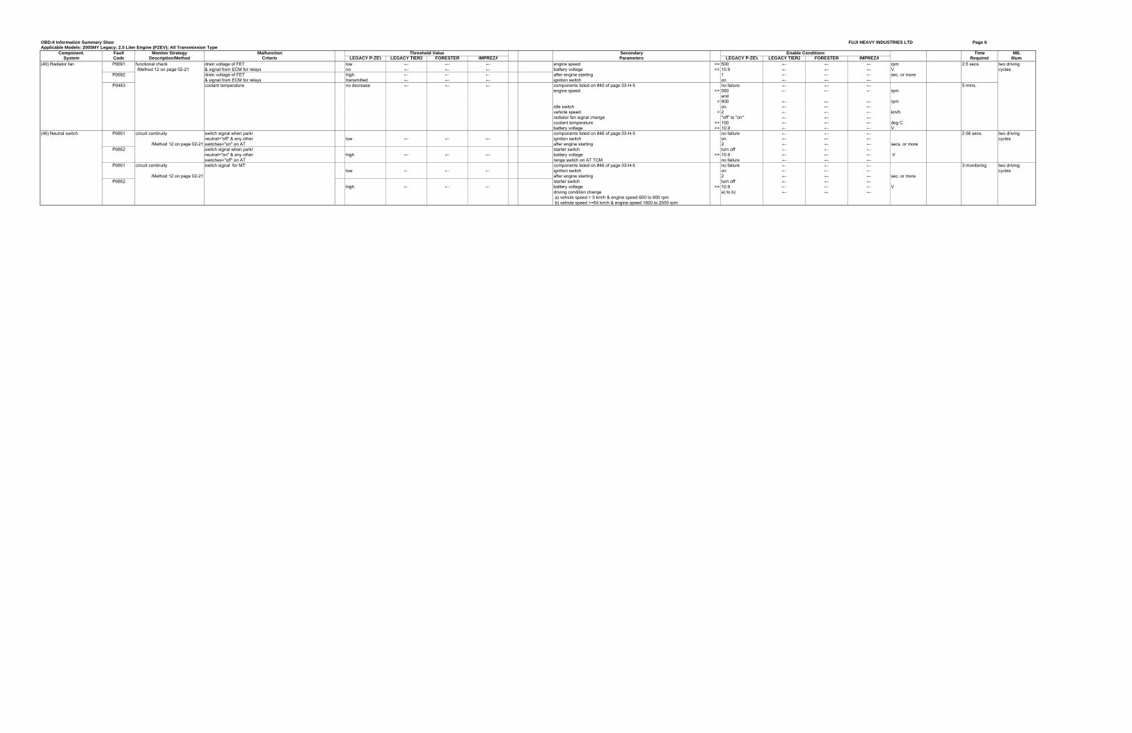
Component/ Fault Monitor Strategy Malfunction Secondary Time MILSystem Code Description/Method Criteria LEGACY P-ZEV LEGACY TIER2 FORESTER IMPREZA Parameters LEGACY P-ZEV LEGACY TIER2 FORESTER IMPREZA Required Illum.
(40) Radiator fan P0691 functional check drain voltage of FET low ← ← ← engine speed >= 500 ← ← ← rpm 2.5 secs. two driving /Method 12 on page 02-21 & signal from ECM for relays no ← ← ← battery voltage >= 10.9 ← ← ← V cycles
P0692 drain voltage of FET high ← ← ← after engine starting 1 ← ← ← sec. or more& signal from ECM for relays transmitted ← ← ← ignition switch on ← ← ←
P0483 coolant temperature no decrease ← ← ← components listed on #40 of page 03-H-5 no failure ← ← ← 5 mins. engine speed >= 560 ← ← ← rpm
and< 900 ← ← ← rpm
idle switch on ← ← ←vehicle speed < 2 ← ← ← km/hradiator fan signal change "off" to "on" ← ← ←coolant temperature >= 100 ← ← ← deg Cbattery voltage >= 10.9 ← ← ← V
(46) Neutral switch P0851 circuit continuity switch signal when park/ components listed on #46 of page 03-H-5 no failure ← ← ← 2.56 secs. two drivingneutral="off" & any other low ← ← ← ignition switch on ← ← ← cycles
/Method 12 on page 02-21 switches="on" on AT after engine starting 2 ← ← ← secs. or moreP0852 switch signal when park/ starter switch turn off ← ← ←
neutral="on" & any other high ← ← ← battery voltage >= 10.9 ← ← ← V switches="off" on AT range switch on AT TCM no failure ← ← ←
P0851 circuit continuity switch signal for MT components listed on #46 of page 03-H-5 no failure ← ← ← 3 monitoring two drivinglow ← ← ← ignition switch on ← ← ← cycles
/Method 12 on page 02-21 after engine starting 2 ← ← ← sec. or moreP0852 starter switch turn off ← ← ←
high ← ← ← battery voltage >= 10.9 ← ← ← V driving condition change a) to b) ← ← ← a) vehicle speed = 0 km/h & engine speed 600 to 900 rpm b) vehicle speed >=64 km/h & engine speed 1600 to 2550 rpm
Threshold Value Enable Conditions
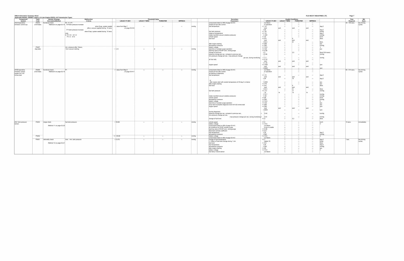
OBD-II Information Summary Sheet FUJI HEAVY INDUSTRIES LTD. Page 7Applicable Models: 2005MY Legacy; 2.5 Liter Engine (PZEV); All Transmission Types
Component/ Fault Monitor Strategy Malfunction Secondary Time MILSystem Code Description/Method Criteria LEGACY P-ZEV LEGACY TIER2 FORESTER IMPREZA Parameters LEGACY P-ZEV LEGACY TIER2 FORESTER IMPREZA Required Illum.
(49) Evaporative P0442 functional check P2 - K x P1 components listed on #49 of page 03-H-5 no failure ← ← ← 30 - 100 secs. two drivingemission control sys. (0.04-leak) /Method 8 on page 02-15 P2=tank pressure increase closed air fuel ratio control in operation ← ← ← cycles
when Evap. system sealed > value from Map 7 ← ← ← mmHg fuel temperature >= -10 ← ← ← deg C after a vacuum applied during 10 secs. on page 03-H-6 and and and and
P1=tank pressure increase < 45 ← ← ← deg Cwhen Evap. system sealed during 10 secs. fuel tank pressure >= -30 ← ← ← mmHg
note; intake air temperature >= -10 ← ← ← deg CK :P1>=0 : K=1.5 intake manifold vacuum (relative pressure) < -200 ← ← ← mmHg P1< 0 : K=0 vehicle speed >= 32 ← ← ← km/h
fuel level >= 9.6 ← 9 ← litersand and and and
< 54.4 ← 51 ← liters after engine starting >= 856 ← ← ← sec
atmospheric pressure >= 563 ← ← ← mmHgP0457 min. pressure after 10secs. battery voltage >= 10.9 ← ← ← V
(big leak) from vacuum starting > -2.5 ← -4 ← mmHg total time of canister purge operation >= 120 ← ← ← seclearning value of EVAP conc. during purge <= 0.08 ← ← ←change of fuel level < 3 ← 2.5 ← liters/128 msecs.pressure change per sec. compare to previous sec. < 0.96 ← ← ← mmHgmin-pressure change per sec.- max-pressure change
per sec. during monitoring < 1.7 ← ← ← mmHgair fuel ratio >= 0.76 ← ← ←
and and and and< 1.25 ← ← ←
engine speed >= 1050 ← ← ← rpmand and and and
< 6000 ← ← ← rpm(49')Evaporative P0456 functional check P1 > value from Map 8 ← ← ← mmHg components listed on #49 of page 03-H-5 no failure ← ← ← 65 - 514 secs. two drivingemission control (0.02-leak) /Method 8 on page 02-15 on page 03-H-7 closed air fuel ratio control in operation ← ← ← cyclessystem for 0.02 (at starting a diagnosis)inches leak fuel temperature >= -10 ← ← ← deg C
and and and and< 55 ← 70 ← deg C
or after engine start with coolant temperature of 40 deg C or below < 2400 ← ← ← secafter engine starting >= 770 ← ← ← secfuel level >= 9.6 ← 9 ← liters
and and and and< 54.4 ← 51 ← liters
fuel tank pressure >= -3.2 ← -5 ← mmHg to to to to
< 10.7 ← ← ← mmHgintake manifold vacuum (relative pressure) < -60 ← ← ← mmHg
vehicle speed >= 68 ← ← ← km/hatmospheric pressure >= 563 ← ← ← mmHgbattery voltage >= 10.9 ← ← ← Vtotal time of canister purge operation >= 120 ← ← ← secsince last incomplete diagnosis event of 0.02 inches leak >= 600 ← ← ← secengine speed >= 550 ← ← ← rpm
and and and and< 6000 ← ← ← rpm
(during diagnosis)pressure change per sec. compare to previous sec. < 0.44 ← ← ← mmHgmin-pressure change per sec.
- max-pressure change per sec. during monitoring < 0.51 ← ← ← mmHgchange of fuel level <= 5 ← 4.2 ← liters
(50) Tank pressure P0453 range check fuel tank pressure > 59.86 ← ← ← mmHg vehicle speed >= 2 ← ← ← km/h 15 secs. immediatelysensor battery voltage >= 10.9 ← ← ← V
/Method 11 on page 02-20 components listed on #50 of page 03-H-5 no failure ← ← ←all conditions for EVAP canister purge to be in enable ← ← ←learning value of EVAP conc. during purge <= 0.08 ← ← ←feed-back lambda coefficient >= 0.9 ← ← ←fuel temperature < 35 ← ← ← deg Catmospheric pressure > 563 ← ← ← mmHg
P0452 <= -55.86 ← ← ← mmHg battery voltage >= 10.9 ← ← ← Vcomponents listed on #50 of page 03-H-5 no failure ← ← ←
P0451 rationality check max. - min. tank pressure < 0.375 ← ← ← mmHg change of fuel temperature >= 7 ← ← ← deg C 1 sec. two driving>= 2liters of fuel level change during 1 min detect 16 ← ← ← times cycles
/Method 12 on page 02-21 fuel level >= 9.6 ← ← ← litersfuel temperature < 35 ← ← ← deg Catmospheric pressure > 563 ← ← ← mmHgafter engine starting >= 60 ← ← ← secbattery voltage >= 10.9 ← ← ← Vfuel temp. & level sensor no failure ← ← ←
Threshold Value Enable Conditions
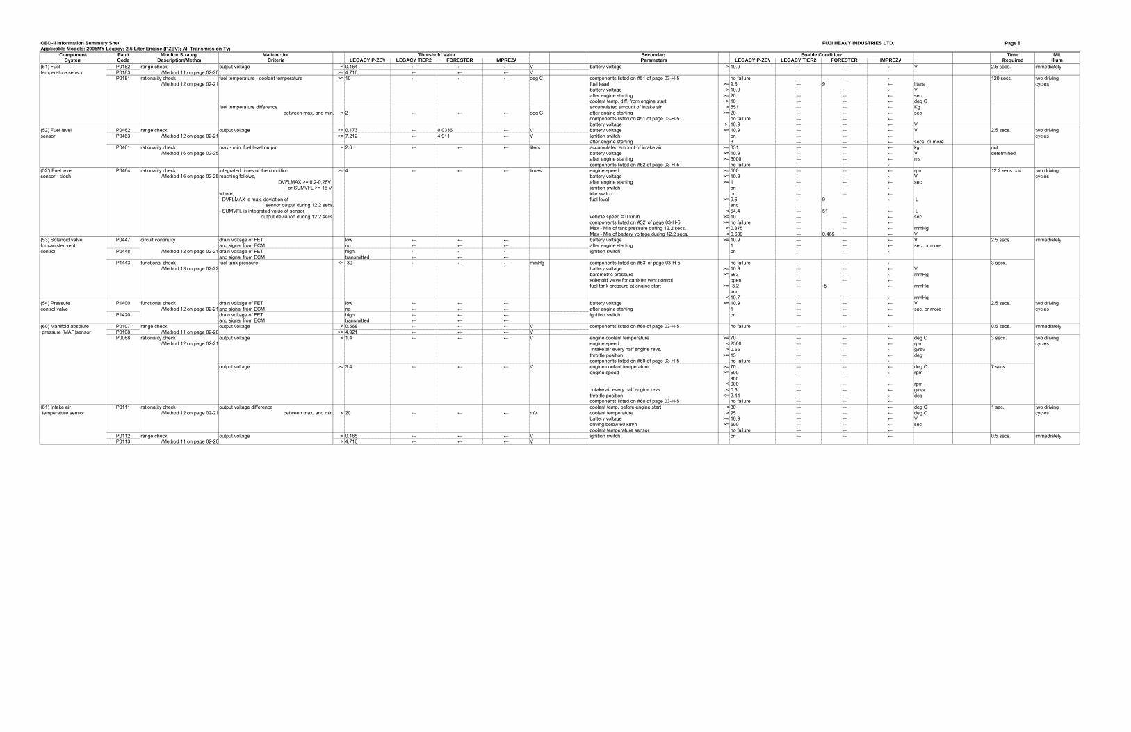
OBD-II Information Summary Shee FUJI HEAVY INDUSTRIES LTD. Page 8Applicable Models: 2005MY Legacy; 2.5 Liter Engine (PZEV); All Transmission Typ
Component/ Fault Monitor Strategy Malfunction Secondary Time MILSystem Code Description/Method Criteria LEGACY P-ZEV LEGACY TIER2 FORESTER IMPREZA Parameters LEGACY P-ZEV LEGACY TIER2 FORESTER IMPREZA Required Illum.
(51) Fuel P0182 range check output voltage < 0.164 ← ← ← V battery voltage > 10.9 ← ← ← V 2.5 secs. immediatelytemperature sensor P0183 /Method 11 on page 02-20 >= 4.716 ← ← ← V
P0181 rationality check fuel temperature - coolant temperature >= 10 ← ← ← deg C components listed on #51 of page 03-H-5 no failure ← ← ← 120 secs. two driving/Method 12 on page 02-21 fuel level >= 9.6 ← 9 ← liters cycles
battery voltage > 10.9 ← ← ← Vafter engine starting >= 20 ← ← ← seccoolant temp. diff. from engine start > 10 ← ← ← deg C
fuel temperature difference accumulated amount of intake air > 551 ← ← ← Kgbetween max. and min. < 2 ← ← ← deg C after engine starting >= 20 ← ← ← sec
components listed on #51 of page 03-H-5 no failure ← ← ←battery voltage > 10.9 ← ← ← V
(52) Fuel level P0462 range check output voltage <= 0.173 ← 0.0336 ← V battery voltage >= 10.9 ← ← ← V 2.5 secs. two drivingsensor P0463 /Method 12 on page 02-21 >= 7.212 ← 4.911 ← V ignition switch on ← ← ← cycles
after engine starting 3 ← ← ← secs. or moreP0461 rationality check max.- min. fuel level output < 2.6 ← ← ← liters accumulated amount of intake air >= 331 ← ← ← kg not
/Method 16 on page 02-25 battery voltage >= 10.9 ← ← ← V determinedafter engine starting >= 5000 ← ← ← ms
components listed on #52 of page 03-H-5 no failure ← ← ←(52') Fuel level P0464 rationality check integrated times of the condition >= 4 ← ← ← times engine speed >= 500 ← ← ← rpm 12.2 secs. x 4 two drivingsensor - slosh /Method 16 on page 02-25 reaching follows, battery voltage >= 10.9 ← ← ← V cycles
DVFLMAX >= 0.2-0.26V after engine starting >= 1 ← ← ← secor SUMVFL >= 16 V ignition switch on ← ← ←
where, idle switch on ← ← ←- DVFLMAX is max. deviation of fuel level >= 9.6 ← 9 ← L
sensor output during 12.2 secs. and- SUMVFL is integrated value of sensor < 54.4 ← 51 ← L
output deviation during 12.2 secs. vehicle speed = 0 km/h >= 10 ← ← ← seccomponents listed on #52' of page 03-H-5 >= no failure ← ← ←Max - Min of tank pressure during 12.2 secs. < 0.375 ← ← ← mmHgMax - Min of battery voltage during 12.2 secs. < 0.609 ← 0.465 ← V
(53) Solenoid valve P0447 circuit continuity drain voltage of FET low ← ← ← battery voltage >= 10.9 ← ← ← V 2.5 secs. immediatelyfor canister vent and signal from ECM no ← ← ← after engine starting 1 ← ← ← sec. or morecontrol P0448 /Method 12 on page 02-21drain voltage of FET high ← ← ← ignition switch on ← ← ←
and signal from ECM transmitted ← ← ←P1443 functional check fuel tank pressure <= -30 ← ← ← mmHg components listed on #53' of page 03-H-5 no failure ← ← ← 3 secs.
/Method 13 on page 02-22 battery voltage >= 10.9 ← ← ← Vbarometric pressure >= 563 ← ← ← mmHgsolenoid valve for canister vent control open ← ← ←fuel tank pressure at engine start >= -3.2 ← -5 ← mmHg
and< 10.7 ← ← ← mmHg
(54) Pressure P1400 functional check drain voltage of FET low ← ← ← battery voltage >= 10.9 ← ← ← V 2.5 secs. two drivingcontrol valve /Method 12 on page 02-21and signal from ECM no ← ← ← after engine starting 1 ← ← ← sec. or more cycles
P1420 drain voltage of FET high ← ← ← ignition switch on ← ← ←and signal from ECM transmitted ← ← ←
(60) Manifold absolute P0107 range check output voltage < 0.568 ← ← ← V components listed on #60 of page 03-H-5 no failure ← ← ← 0.5 secs. immediately pressure (MAP)sensor P0108 /Method 11 on page 02-20 >= 4.921 ← ← ← V
P0068 rationality check output voltage < 1.4 ← ← ← V engine coolant temperature >= 70 ← ← ← deg C 3 secs. two driving/Method 12 on page 02-21 engine speed < 2500 ← ← ← rpm cycles
intake air every half engine revs. > 0.55 ← ← ← g/revthrottle position >= 13 ← ← ← degcomponents listed on #60 of page 03-H-5 no failure ← ← ←
output voltage >= 3.4 ← ← ← V engine coolant temperature >= 70 ← ← ← deg C 7 secs.engine speed >= 600 ← ← ← rpm
and< 900 ← ← ← rpm
intake air every half engine revs. < 0.5 ← ← ← g/revthrottle position <= 2.44 ← ← ← degcomponents listed on #60 of page 03-H-5 no failure ← ← ←
(61) Intake air P0111 rationality check output voltage difference coolant temp. before engine start < 30 ← ← ← deg C 1 sec. two driving temperature sensor /Method 12 on page 02-21 between max. and min. < 20 ← ← ← mV coolant temperature > 95 ← ← ← deg C cycles
battery voltage >= 10.9 ← ← ← Vdriving below 60 km/h >= 600 ← ← ← seccoolant temperature sensor no failure ← ← ←
P0112 range check output voltage < 0.165 ← ← ← V ignition switch on ← ← ← 0.5 secs. immediatelyP0113 /Method 11 on page 02-20 > 4.716 ← ← ← V
Threshold Value Enable Conditions
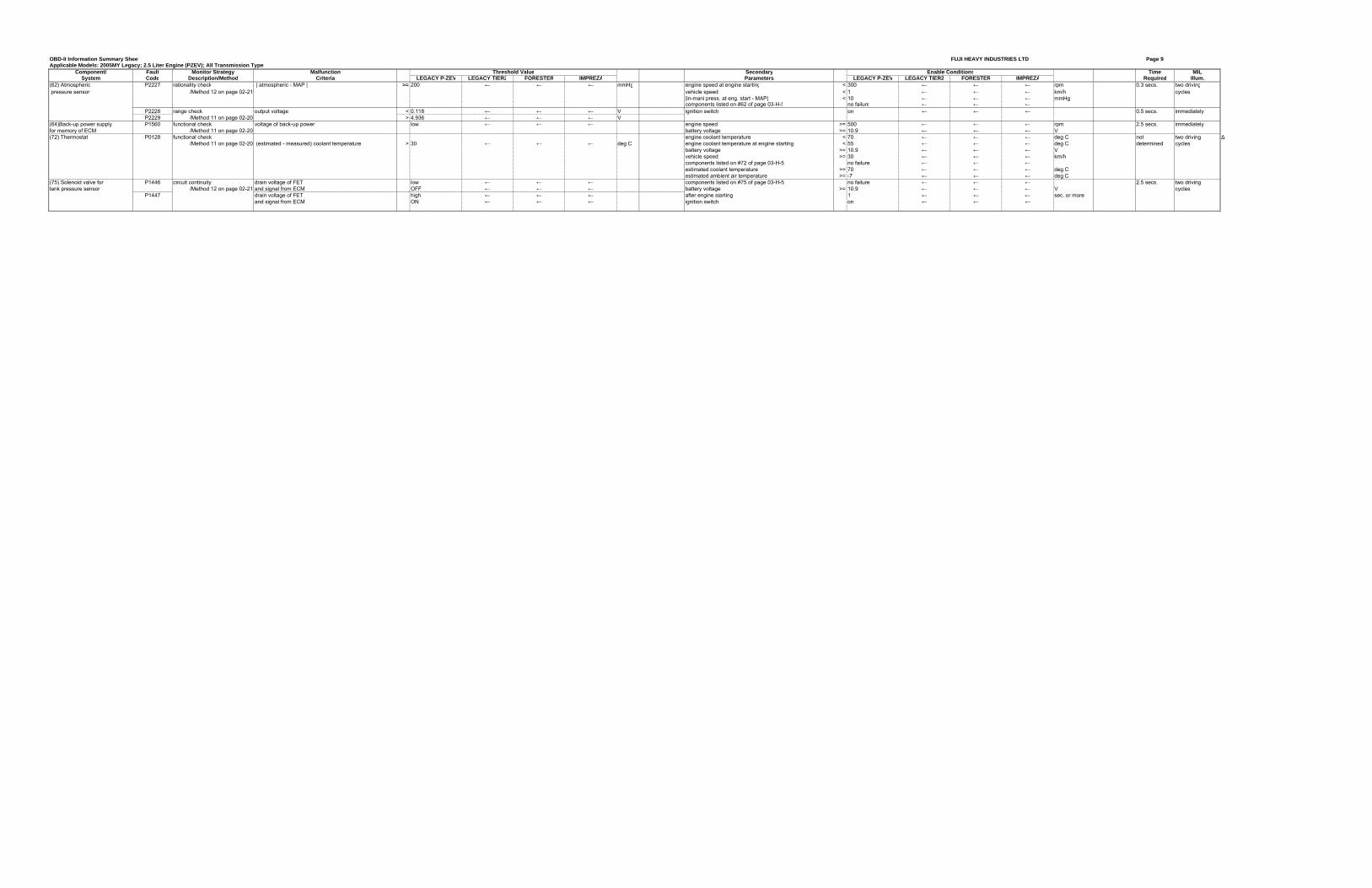
OBD-II Information Summary Sheet FUJI HEAVY INDUSTRIES LTD Page 9Applicable Models: 2005MY Legacy; 2.5 Liter Engine (PZEV); All Transmission Types
Component/ Fault Monitor Strategy Malfunction Secondary Time MILSystem Code Description/Method Criteria LEGACY P-ZEV LEGACY TIER2 FORESTER IMPREZA Parameters LEGACY P-ZEV LEGACY TIER2 FORESTER IMPREZA Required Illum.
(62) Atmospheric P2227 rationality check | atmospheric - MAP | >= 200 ← ← ← mmHg engine speed at engine starting < 300 ← ← ← rpm 0.3 secs. two driving pressure sensor /Method 12 on page 02-21 vehicle speed < 1 ← ← ← km/h cycles
|in-mani press. at eng. start - MAP| < 10 ← ← ← mmHgcomponents listed on #62 of page 03-H-5 no failure ← ← ←
P2228 range check output voltage < 0.118 ← ← ← V ignition switch on ← ← ← 0.5 secs. immediatelyP2229 /Method 11 on page 02-20 > 4.936 ← ← ← V
(64)Back-up power supply P1560 functional check voltage of back-up power low ← ← ← engine speed >= 500 ← ← ← rpm 2.5 secs. immediatelyfor memory of ECM /Method 11 on page 02-20 battery voltage >= 10.9 ← ← ← V(72) Thermostat P0128 functional check engine coolant temperature < 70 ← ← ← deg C not two driving ∆
/Method 11 on page 02-20 (estimated - measured) coolant temperature > 30 ← ← ← deg C engine coolant temperature at engine starting < 55 ← ← ← deg C determined cyclesbattery voltage >= 10.9 ← ← ← Vvehicle speed >= 30 ← ← ← km/hcomponents listed on #72 of page 03-H-5 no failure ← ← ←estimated coolant temperature >= 70 ← ← ← deg Cestimated ambient air temperature >= -7 ← ← ← deg C
(75) Solenoid valve for P1446 circuit continuity drain voltage of FET low ← ← ← components listed on #75 of page 03-H-5 no failure ← ← ← 2.5 secs. two drivingtank pressure sensor /Method 12 on page 02-21 and signal from ECM OFF ← ← ← battery voltage >= 10.9 ← ← ← V cycles
P1447 drain voltage of FET high ← ← ← after engine starting 1 ← ← ← sec. or moreand signal from ECM ON ← ← ← ignition switch on ← ← ←
Threshold Value Enable Conditions
OBD-II Information Summary Shee FUJI HEAVY INDUSTRIES LTD Page 10Applicable Models: 2005MY Legacy; 2.5 Liter Engine (PZEV); All Transmission Ty
Component/ Fault Monitor Strategy Malfunction Secondary Time MILSystem Code Description/Method Criteria LEGACY P-ZEV LEGACY TIER2 FORESTER IMPREZA Parameters LEGACY P-ZEV LEGACY TIER2 FORESTER IMPREZA Required Illum.
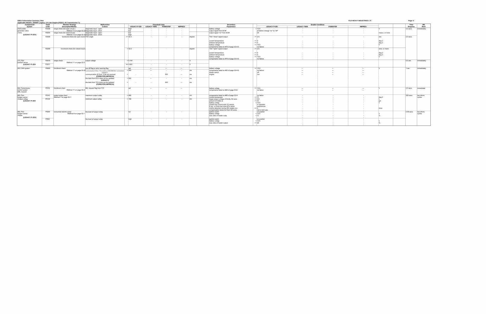
(76)Tumble P2006 range check (for open circuit ) diagnostic input - open high - - - battery voltage > 10.9 - - - V 3.5 secs. immediatelygenerator valve /Method 13 on page 02-22diagnostic input - short low - - - output signal from ECM at before change "on" to "off" - - -(TGV) P2004 range check (for short circuit) diagnostic input - open low - - - output signal "on" from ECM 20 - - - msecs. or more
(LEGACY P-ZEV) /Method 13 on page 02-22diagnostic input - short high - - -P2008 functional check (for open stuck)TGV angle >= 52.5 - - - degree TGV "close" signal output >= 2.5 - - - sec 2.5 secs.
coolant temperature >= 0 - - - deg Cambient temperature >= 0 - - - deg Cbattery voltage >= 10.9 - - - Vcomponents listed on #76 of page 03-H-5 no failure - - -
P2009 functional check (for closed stuck) < 52.5 - - - degree TGV "open" signal output >= 2.5 - - - secs. or more
coolant temperature >= 0 - - - deg Cambient temperature >= 0 - - - deg Cbattery voltage >= 10.9 - - - Vcomponents listed on #76 of page 03-H-5 no failure - - -
(77) TGV P2016 range check output voltage < 0.181 - - - V 0.5 sec. immediatelyposition sensor /Method 11 on page 02-20
(LEGACY P-ZEV) P2017 >= 4.843 - - - V
(83) CAN system P0600 functional check bus off flag or error warning flag set ← ← ← battery voltage >= 10.9 ← ← ← V 1 sec immediately/Method 11 on page 02-20 = 500 ← - - ms components listed on #83 of page 03-H-5 no failure ← ← ←
starter switch off ← ← ←communication ID from TCM not received = - - 500 ← ms engine run ← ← ←
(FORESTER,IMPREZA)the data from ECU does not be updated = 500 ← - - ms
(LEGACY)the data from TCU does not be updated = - - 500 ← ms
(FORESTER,IMPREZA)
(84) Transmission P0700 functional check MIL request flag from TCM set ← ← ← battery voltage >= 10.9 ← ← ← V 2.5 secs. immediatelycontrol system /Method 11 on page 02-20 components listed on #84 of page 03-E- no failure ← ← ←(MIL request)
(85) Third P0143 output range check maximum output voltag < 400 - - - mV components listed on #85 of page 03-H- no failure - - - 320 secs. two drivingoxygen senso /Method 7 on page 02-13 coolant temperature >= 70 - - - deg C cycles-Output voltage P0144 minimum output voltag > 150 - - - mV target output voltage of thirdly O2 senso >= 0.6 - - - V
(LEGACY P-ZEV) amount of intake ai >= 30 - - - g/sbattery voltage > 10.9 - - - Vclosed loop control with O2 sensors in operation - - -6 sec. or more fuel shut-off in decel experienced - - -misfire detection during 200 engine revs <= 5 - - - timescompensation factor for front O2 senso not in limit value - - -
(86) Third P0044 consumed electric powe the level of output voltag low - - - ignition switch on position - - - 2.56 secs. two drivingoxygen senso /Method 6 on page 02-11 battery voltage > 10.9 - - - V cycles-Heater duty ratio of heater outpu < 75 - - - %
(LEGACY P-ZEV) - - -P0043 the level of output voltag high - - - ignition switch on position - - -
battery voltage > 10.9 - - - Vduty ratio of heater output >= 20 - - - %
- - -
Threshold Value Enable Conditions
communication ID from TCU or ECU or VDC/ABS ECU not received (LEGACY)
OBD-II Information Summary Sheet FUJI HEAVY INDUSTRIES LTD Page 11Applicable Models: 2005MY Legacy; 2.5 Liter Engine (PZEV); All Transmission Types
Component/ Fault Monitor Strategy Malfunction Secondary Time MILSystem Code Description/Method Criteria LEGACY P-ZEV LEGACY TIER2 FORESTER IMPREZA Parameters LEGACY P-ZEV LEGACY TIER2 FORESTER IMPREZA Required Illum.
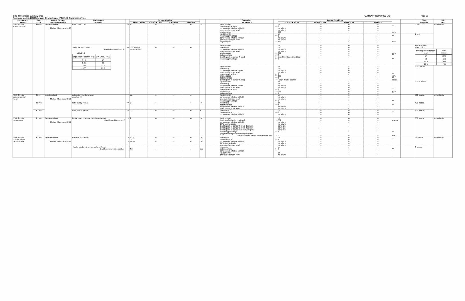
(201) Throttle P0638 functional check motor control Duty >= 95 ← ← ← % ignition switch on ← ← ← 5 sec. immediatelyactuator control motor supply voltage >= 6 ← ← ← V
/Method 11 on page 02-20 components listed on table 20 no failure ← ← ←previous diagnosis result no failure ← ← ←engine speed < 500 ← ← ← rpmignition switch on ← ← ← 2 sec.motor supply voltage >= 6 ← ← ← Vcomponents listed on table 20 no failure ← ← ←previous diagnosis result no failure ← ← ←engine speed >= 500 ← ← ← rpm
ignition switch on ← ← ← see table 21-2| target throttle position - >= ETCOMNG ← ← ← motor relay on ← ← ← table 21-2
throttle position sensor 1 | see table 21-1 components listed on table 20 no failure ← ← ←previous diagnosis result no failure ← ← ←
table 21-1 engine speed >= 500 ← ← ← rpmbattery voltage >= 6 ← ← ← Vthrottle position sensor 1 (deg) >= target throttle position (deg) ← ← ←motor supply voltage >= 6 ← ← ← V
ignition switch on ← ← ← 1000 msecs.motor relay on ← ← ←components listed on table20 no failure ← ← ←previous diagnosis result no failure ← ← ←motor supply voltage >= 6 ← ← ← Vengine speed >= 500 ← ← ← rpmbattery voltage >= 6 ← ← ← Vthrottle position sensor 1 (deg) < target throttle position ← ← ← (deg)ignition switch on ← ← ← 20000 msecs.motor relay on ← ← ←components listed on table20 no failure ← ← ←previous diagnosis result no failure ← ← ←motor supply voltage >= 6 ← ← ← Vengine speed < 500 ← ← ← rpmbattery voltage >= 6 ← ← ← V
(202) Throttle P2101 circuit continuity malfunction flag from motor set ← ← ← ignition switch on ← ← ← 496 msecs. immediatelyactuator control operation IC components listed on table 20 no failure ← ← ←motor /Method 11 on page 02-20 previous diagnosis result no failure ← ← ←
motor supply voltage >= 6 ← ← ← VP2102 motor supply voltage <= 5 ← ← ← V motor relay on ← ← ← 400 msecs.
battery voltage >= 6 ← ← ← Vcomponents listed on table 20 no failure ← ← ←previous diagnosis result no failure ← ← ←
P2103 motor supply voltage >= 5 ← ← ← V motor relay off ← ← ← 600 msecs.battery voltage >= 6 ← ← ← Vcomponents listed on table 20 no failure ← ← ←
(203) Throttle P1160 functional check throttle position sensor 1 at diagnosis start < 2 ← ← ← deg. ignition switch off ← ← ← 600 msecs. immediatelyreturn spring - throttle position sensor 1 the time after ignition switch off = 992 ← ← ← msecs.
/Method 11 on page 02-20 components listed on table 20 no failure ← ← ←CPU communication no failure ← ← ←throttle position sensor 1 circuit diagnosis complete ← ← ←throttle position sensor 2 circuit diagnosis complete ← ← ←throttle position sensor rationality diagnosis complete ← ← ←motor supply voltage >= 6 ← ← ← V| target throttle position at diagnosis start
- throttle position sensor 1 at diagnosis start | < 2 ← ← ← deg.(204) Throttle P2109 rationality check minimum stop position < 10.31 ← ← ← deg motor relay on ← ← ← 16 msecs. immediatelyposition sensor or battery voltage >= 6 ← ← ← Vminimum stop /Method 11 on page 02-20 > 19.69 ← ← ← deg components listed on table 20 no failure ← ← ←
CPU communication no failure ← ← ←previous diagnosis result no failure ← ← ←
| throttle position at ignition switch off to on motor relay on ← ← ← 8 msecs.- throttle minimum stop position < 1.8 ← ← ← deg battery voltage >= 6 ← ← ← V
components listed on table 20ignition switch on ← ← ←previous diagnosis result no failure ← ← ←
Threshold Value Enable Conditions
ETCOMNG (deg)
3.55.012.025.0
target throttle position (deg)
6.15
14.659.65
26.65
throttle position sensor1 (deg)
time msecs.
1000400300250
5.5
13.09.0
22.0
OBD-II Information Summary Sheet FUJI HEAVY INDUSTRIES LTD. Page 12Applicable Models: 2005MY Legacy; 2.5 Liter Engine (PZEV); All Transmission Types
Component/ Fault Monitor Strategy Malfunction Secondary Time MILSystem Code Description/Method Criteria LEGACY P-ZEV LEGACY TIER2 FORESTER IMPREZA Parameters LEGACY P-ZEV LEGACY TIER2 FORESTER IMPREZA Required Illum.
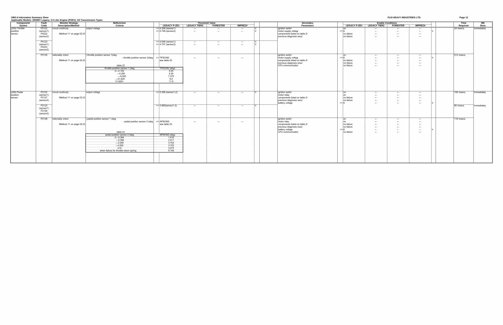
(205) Throttle P0122 circuit continuity output voltage <= 0.309 (sensor1) ← ← ← V ignition switch on ← ← ← 24 msecs. immediatelyposition (sensor1) <= 0.749 (sensor2) ← ← ← V motor supply voltage >= 6 ← ← ← Vsensor P0222 /Method 11 on page 02-20 components listed on table 20 no failure ← ← ←
(sensor2) previous diagnosis result no failure ← ← ←
P0123 >= 4.646 (sensor1) ← ← ← V(sensor1) >= 4.747 (sensor2) ← ← ← V
P0223(sensor2)
P2135 rationality check | throttle position sensor 1(deg) ignition switch on ← ← ← 212 msecs.- throttle position sensor 2(deg) >= TPSCNG ← ← ← motor supply voltage >= 6 ← ← ← V
/Method 11 on page 02-20 see table 22 components listed on table 20 no failure ← ← ←previous diagnosis result no failure ← ← ←
table 22 CPU communication no failure ← ← ←throttle position sensor 1 (deg) TPSCNG (deg)
0---2.125 4.25 ---4.250 5.25
---9.000 7.375 ---31.625 9.5 31.625< 11.5
(206) Pedal P2122 circuit continuity output voltage <= 0.308 (sensor1,2) ← ← ← V ignition switch on ← ← ← 100 msecs. immediatelyposition (sensor1) motor relay on ← ← ←sensor P2127 /Method 11 on page 02-20 components listed on table 20 no failure ← ← ←
(sensor2) previous diagnosis result no failure ← ← ←battery voltage >= 6 ← ← ← V
P2123 >= 4.865(sensor1,2) ← ← ← V 80 msecs. immediately(sensor1)
P2128(sensor2)
P2138 rationality check | pedal position sensor 1 (deg) ignition switch on ← ← ← 116 msecs.- pedal position sensor 2 (deg) >= APSCNG ← ← ← motor relay on ← ← ←
/Method 11 on page 02-20 see table 23 components listed on table 20 no failure ← ← ←previous diagnosis result no failure ← ← ←battery voltage >= 6 ← ← ← V
table 23 CPU communication no failure ← ← ←pedal position sensor 2 (deg) APSCNG (deg)
0---0.384 1.616 ---2.384 2.411---3.000 3.703---4.000 3.703
4.0< 3.073when failure for throttle return spring 9.109
Threshold Value Enable Conditions
OBD-II Information Summary Sheet FUJI HEAVY INDUSTRIES LTD. Page 13Applicable Models: 2005MY Legacy; 2.5 Liter Engine (PZEV); All Transmission Types
Component/ Fault Monitor Strategy Malfunction Secondary Time MILSystem Code Description/Method Criteria LEGACY P-ZEV LEGACY TIER2 FORESTER IMPREZA Parameters LEGACY P-ZEV LEGACY TIER2 FORESTER IMPREZA Required Illum.
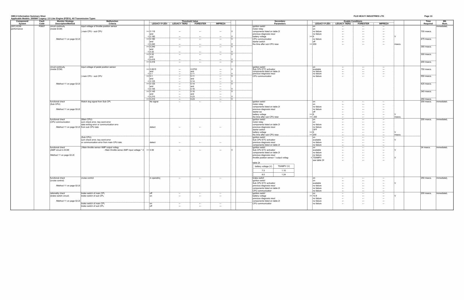
(207) ECM P0607 circuit continuity input voltage of throttle position sensor 1 ignition switch on ← ← ← immediatelyperformance (inside ECM) motor relay on ← ← ←
| main CPU - sub CPU >= 0.116 ← ← ← V components listed on table 20 no failure ← ← ← 700 msecs.and previous diagnosis result no failure ← ← ←
< 0.180 ← ← ← V battery voltage >= 6 ← ← ← V/Method 11 on page 02-20 >= 0.180 ← ← ← V CPU communication no failure ← ← ← 475 msecs.
and starter switch off ← ← ←< 0.240 ← ← ← V the time after sub CPU reset >= 200 ← ← ← msecs.
>= 0.240 ← ← ← V 350 msecs.and
< 0.32 ← ← ← V>= 0.32 ← ← ← V 300 msecs.
and< 0.416 ← ← ← V
>= 0.416 ← ← ← V 200 msecs.
circuit continuity input voltage of pedal position sensor 1 ignition switch on ← ← ←(inside ECM) >= 0.0615 ← 0.0703 ← V Sub CPU ETC activation available ← ← ← 750 msecs.
and ← and ← components listed on table 20 no failure ← ← ←< 0.1 ← 0.11 ← V previous diagnosis result no failure ← ← ←
| main CPU - sub CPU >= 0.1 ← 0.11 ← V CPU communication no failure ← ← ← 550 msecs.and ← and ←
< 0.125 ← 0.14 ← V/Method 11 on page 02-20 >= 0.125 ← 0.14 ← V 425 msecs.
and ← and ←< 0.145 ← 0.16 ← V
>= 0.145 ← 0.16 ← V 340 msecs.and ← and ←
< 0.210 ← 0.23 ← V>= 0.210 ← 0.23 ← V 250 msecs.
functional check Watch dog signal from Sub CPU No signal ← ← ← ignition switch on ← ← ← 200 msecs. immediately(Sub CPU) motor relay on ← ← ←
components listed on table 20 no failure ← ← ←/Method 11 on page 02-20 previous diagnosis result no failure ← ← ←
starter sw off ← ← ←battery voltage >= 6 ← ← ← Vthe time after sub CPU reset >= 200 ← ← ← msecs.
functional check (Main CPU) ignition switch on ← ← ← 200 msecs. immediately(CPU communication) sum check error, key word error, motor relay on ← ← ←
data writing error or communication erro components listed on table 20 no failure ← ← ←/Method 11 on page 02-20 from sub CPU data detect ← ← ← previous diagnosis result no failure ← ← ←
starter switch OFF ← ← ←battery voltage >= 6 ← ← ← Vthe time after sub CPU reset >= 200 ← ← ← msecs.
(Sub CPU) ignition switch on ← ← ←sum check error, key word error, Sub CPU ETC activation available ← ← ← Vor communication error from main CPU data detect ← ← ← previous diagnosis result no failure ← ← ←
components listed on table 20 no failure ← ← ←functional check | Main throttle sensor AMP output voltage ignition switch on ← ← ← 24 msecs. immediately(AMP circuit in ECM) - Main throttle senso AMP input voltage * 4 >= 0.56 ← ← ← V Sub CPU ETC activation available ← ← ← V
components listed on table 20 no failure ← ← ←/Method 11 on page 02-20 previous diagnosis result no failure ← ← ←
throttle position sensor 1 output voltage < TSAMPV ← ← ← Vsee table 24 ← ← ←
table 24
functional check cruise control in operating ← ← ← brake switch on ← ← ← 250 msecs. immediately(cruise control) ignition switch on ← ← ←
Sub CPU ETC activation available ← ← ← V/Method 11 on page 02-20 previous diagnosis result no failure ← ← ←
components listed on table 20 no failure ← ← ←CPU communication no failure ← ← ←
rationality check brake switch of main CPU off ← ← ← ignition switch on ← ← ← 200 msecs. immediately(brake switch circuit) brake switch of sub CPU on ← ← ← battery voltage >= 10.9 ← ← ← V
previous diagnosis result no failure ← ← ←/Method 11 on page 02-20 components listed on table 20 no failure ← ← ←
brake switch of main CPU on ← ← ← CPU communication no failure ← ← ←brake switch of sub CPU off ← ← ←
Enable ConditionsThreshold Value
battery voltage (V) TSAMPV (V)
7.5
8.0 1.24
1.10
OBD-II Information Summary Sheet FUJI HEAVY INDUSTRIES LTD. Page 14Applicable Models: 2005MY Legacy; 2.5 Liter Engine (PZEV); All Transmission Types
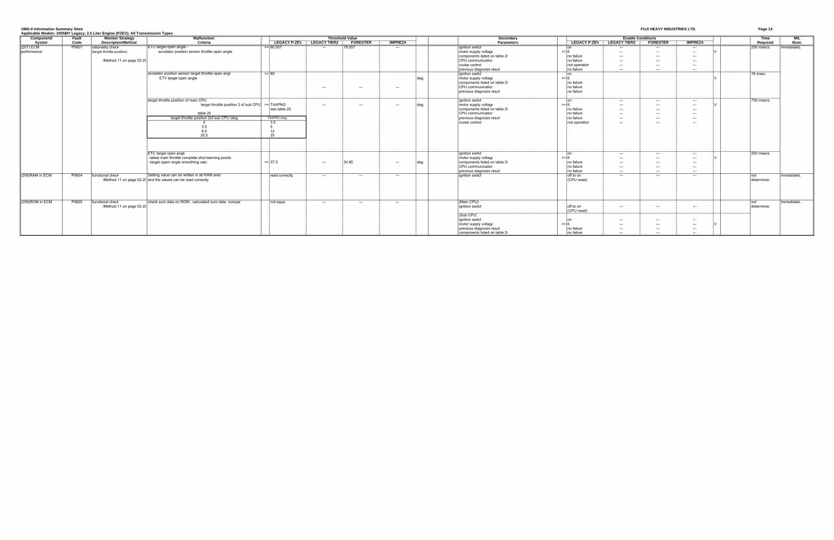
Component/ Fault Monitor Strategy Malfunction Secondary Time MILSystem Code Description/Method Criteria LEGACY P-ZEV LEGACY TIER2 FORESTER IMPREZA Parameters LEGACY P-ZEV LEGACY TIER2 FORESTER IMPREZA Required Illum.
(207) ECM P0607 rationality check >= 80.507 ← 78.057 ← ignition switch on ← ← ← 250 msecs. immediatelyperformance (target throttle position) motor supply voltage >= 6 ← ← ← V
components listed on table 20 no failure ← ← ←/Method 11 on page 02-20 CPU communication no failure ← ← ←
cruise control not operation ← ← ←previous diagnosis result no failure ← ← ←
>= 90 ignition switch on 16 msecdeg. motor supply voltage >= 6 V
components listed on table 20 no failure← ← ← CPU communication no failure
previous diagnosis result no failure
target throttle position of main CPU ignition switch on ← ← ← 750 msecs.target throttle position 2 of sub CPU >= TAAPNG ← ← ← deg. motor supply voltage >= 6 ← ← ← V
see table 25 components listed on table 20 no failure ← ← ←table 25 CPU communication no failure ← ← ←
target throttle position 2of sub CPU (deg ��TAAPNG (deg) previous diagnosis result no failure ← ← ←0 3.5 cruise control not operation ← ← ←
3.5 58.5 1220.5 25
�ETC target open angle ignition switch on ← ← ← 200 msecs.
� -latest main throttle complete shut learning positio motor supply voltage >= 6 ← ← ← V -target opem angle smoothing value >= 37.3 ← 34.85 ← deg components listed on table 20 no failure ← ← ←
CPU communication no failure ← ← ←previous diagnosis result no failure ← ← ←
(208)RAM in ECM P0604 functional check read correctly ← ← ← ignition switch off to on ← ← ← not immediately/Method 11 on page 02-20 (CPU reset) determined
(209)ROM in ECM P0605 functional check check sum data on ROM , calculated sum data compar not equa ← ← ← (Main CPU) not immediately/Method 11 on page 02-20 ignition switch off to on ← ← ← determined
(CPU reset)(Sub CPU) �
� ignition switch on ← ← ←motor supply voltage >= 6 ← ← ← Vprevious diagnosis result no failure ← ← ←components listed on table 20 no failure ← ← ←
Setting value can be written in all RAM areaand the values can be read correctly
Threshold Value Enable Conditions
ETC target open angle - accelator position sensor throttle open angle
accelator position sensor target throttle open angle ETV target open angle
OBD-II Information Summary Sheet FUJI HEAVY INDUSTRIES LTD. Page 15Applicable Models: 2005MY Legacy; 2.5 Liter Engine (PZEV); All Transmission Types
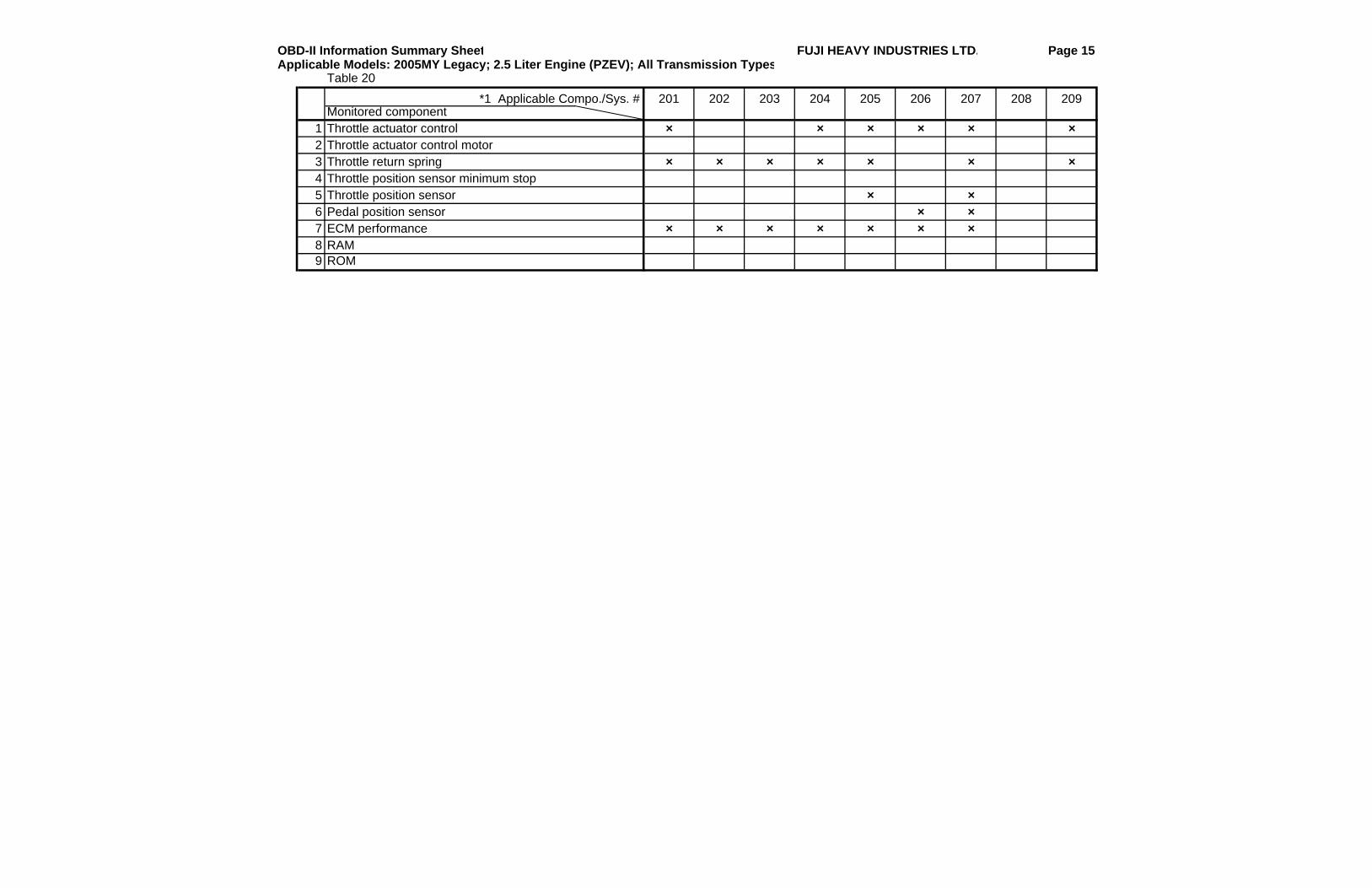
Table 20
*1 Applicable Compo./Sys. # 201 202 203 204 205 206 207 208 209Monitored component
1 Throttle actuator control × × × × × ×2 Throttle actuator control motor3 Throttle return spring × × × × × × ×4 Throttle position sensor minimum stop5 Throttle position sensor × ×6 Pedal position sensor × ×7 ECM performance × × × × × × ×8 RAM9 ROM
OBD-II Information Summary Sheet FUJI HEAVY INDUSTRIES LTD. Page 16Applicable Models: 2005MY Legacy; 2.5 Liter Engine (PZEV); All Transmission Types
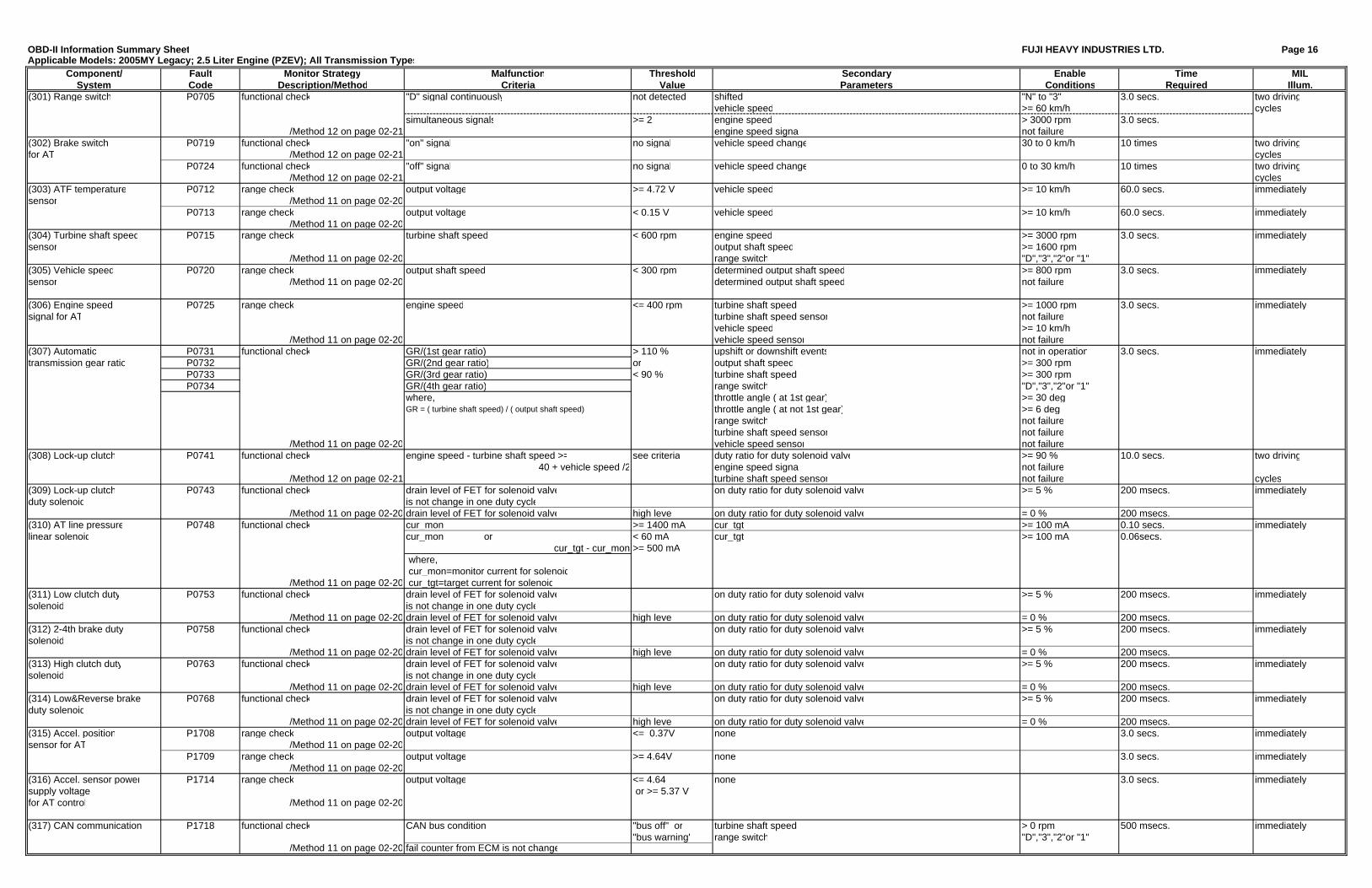
Component/ Fault Monitor Strategy Malfunction Threshold Secondary Enable Time MILSystem Code Description/Method Criteria Value Parameters Conditions Required Illum.
(301) Range switch P0705 functional check "D" signal continuously not detected shifted "N" to "3" 3.0 secs. two drivingvehicle speed >= 60 km/h cycles
simultaneous signals >= 2 engine speed > 3000 rpm 3.0 secs./Method 12 on page 02-21 engine speed signa not failure
(302) Brake switch P0719 functional check "on" signal no signal vehicle speed change 30 to 0 km/h 10 times two drivingfor AT /Method 12 on page 02-21 cycles
P0724 functional check "off" signal no signal vehicle speed change 0 to 30 km/h 10 times two driving/Method 12 on page 02-21 cycles
(303) ATF temperature P0712 range check output voltage >= 4.72 V vehicle speed >= 10 km/h 60.0 secs. immediatelysensor /Method 11 on page 02-20
P0713 range check output voltage < 0.15 V vehicle speed >= 10 km/h 60.0 secs. immediately/Method 11 on page 02-20
(304) Turbine shaft speed P0715 range check turbine shaft speed < 600 rpm engine speed >= 3000 rpm 3.0 secs. immediatelysensor output shaft speed >= 1600 rpm
/Method 11 on page 02-20 range switch "D","3","2"or "1"(305) Vehicle speed P0720 range check output shaft speed < 300 rpm determined output shaft speed >= 800 rpm 3.0 secs. immediatelysensor /Method 11 on page 02-20 determined output shaft speed not failure
(306) Engine speed P0725 range check engine speed <= 400 rpm turbine shaft speed >= 1000 rpm 3.0 secs. immediatelysignal for AT turbine shaft speed sensor not failure
vehicle speed >= 10 km/h/Method 11 on page 02-20 vehicle speed sensor not failure
(307) Automatic P0731 functional check GR/(1st gear ratio) > 110 % upshift or downshift events not in operation 3.0 secs. immediatelytransmission gear ratio P0732 GR/(2nd gear ratio) or output shaft speed >= 300 rpm
P0733 GR/(3rd gear ratio) < 90 % turbine shaft speed >= 300 rpmP0734 GR/(4th gear ratio) range switch "D","3","2"or "1"
where, throttle angle ( at 1st gear) >= 30 degGR = ( turbine shaft speed) / ( output shaft speed) throttle angle ( at not 1st gear) >= 6 deg
range switch not failureturbine shaft speed sensor not failure
/Method 11 on page 02-20 vehicle speed sensor not failure(308) Lock-up clutch P0741 functional check engine speed - turbine shaft speed >= see criteria duty ratio for duty solenoid valve >= 90 % 10.0 secs. two driving
40 + vehicle speed /2 engine speed signa not failure/Method 12 on page 02-21 turbine shaft speed sensor not failure cycles
(309) Lock-up clutch P0743 functional check drain level of FET for solenoid valve on duty ratio for duty solenoid valve >= 5 % 200 msecs. immediatelyduty solenoid is not change in one duty cycle
/Method 11 on page 02-20 drain level of FET for solenoid valve high leve on duty ratio for duty solenoid valve = 0 % 200 msecs.(310) AT line pressure P0748 functional check cur_mon >= 1400 mA cur_tgt >= 100 mA 0.10 secs. immediatelylinear solenoid cur_mon or < 60 mA cur_tgt >= 100 mA 0.06secs.
cur_tgt - cur_mon >= 500 mA where, cur_mon=monitor current for solenoid
/Method 11 on page 02-20 cur_tgt=target current for solenoid(311) Low clutch duty P0753 functional check drain level of FET for solenoid valve on duty ratio for duty solenoid valve >= 5 % 200 msecs. immediatelysolenoid is not change in one duty cycle
/Method 11 on page 02-20 drain level of FET for solenoid valve high leve on duty ratio for duty solenoid valve = 0 % 200 msecs.(312) 2-4th brake duty P0758 functional check drain level of FET for solenoid valve on duty ratio for duty solenoid valve >= 5 % 200 msecs. immediatelysolenoid is not change in one duty cycle
/Method 11 on page 02-20 drain level of FET for solenoid valve high leve on duty ratio for duty solenoid valve = 0 % 200 msecs.(313) High clutch duty P0763 functional check drain level of FET for solenoid valve on duty ratio for duty solenoid valve >= 5 % 200 msecs. immediatelysolenoid is not change in one duty cycle
/Method 11 on page 02-20 drain level of FET for solenoid valve high leve on duty ratio for duty solenoid valve = 0 % 200 msecs.(314) Low&Reverse brake P0768 functional check drain level of FET for solenoid valve on duty ratio for duty solenoid valve >= 5 % 200 msecs. immediatelyduty solenoid is not change in one duty cycle
/Method 11 on page 02-20 drain level of FET for solenoid valve high leve on duty ratio for duty solenoid valve = 0 % 200 msecs.(315) Accel. position P1708 range check output voltage <= 0.37V none 3.0 secs. immediatelysensor for AT /Method 11 on page 02-20
P1709 range check output voltage >= 4.64V none 3.0 secs. immediately/Method 11 on page 02-20
(316) Accel. sensor power P1714 range check output voltage <= 4.64 none 3.0 secs. immediatelysupply voltage or >= 5.37 Vfor AT control /Method 11 on page 02-20
(317) CAN communication P1718 functional check CAN bus condition "bus off" or turbine shaft speed > 0 rpm 500 msecs. immediately"bus warning" range switch "D","3","2"or "1"
/Method 11 on page 02-20 fail counter from ECM is not change