0471b0001a operating manual pherastar fs fs... · although these instructions were carefully...
TRANSCRIPT

Operating Manual
Revision A

PHERAstar FS Operating Manual BMG LABTECH
2/26 0471B0001A 2009-09-22
This manual was designed to guide PHERAstar FS users through the basic hardware features of the microplate reader instrument.
Although these instructions were carefully written and checked, we cannot accept responsibility for problems encountered when using this manual. Suggestions for improving this manual will be gratefully accepted.
BMG LABTECH reserves the right to change or update this manual at any time. The revision number is stated at the bottom of every page. For contact information please visit www.bmglabtech.com or send an email to [email protected]
Copyright 2009 BMG LABTECH. All rights reserved. All BMG LABTECH brand and product names are trademarks of BMG LABTECH. Other brand and product names are trademarks or registered trademarks of their respective holders.

BMG LABTECH PHERAstar FS Operating Manual
2009-09-22 0471B0001A 3/26
The PHERAstar FS is a multifunctional microplate reader that can perform a wide variety of applications for fluorescence intensity, fluorescence polarization, time-resolved fluorescence, HTRF®, luminescence, AlphaScreen® and full spectrum absorbance. The PHERAstar FS has high-end performance in all plate formats and in all detection modes. By using proprietary technology in a variety of important parts, the PHERAstar FS will deliver high-end results.
PHERAstar FS

PHERAstar FS Operating Manual BMG LABTECH
4/26 0471B0001A 2009-09-22
TABLE OF CONTENTS
1 TECHNICAL SPECIFICATIONS 5
2 OVERVIEW 7 2.1 FRONT AND RIGHT SIDE OF PHERASTAR FS 7 2.2 BACK OF PHERASTAR FS 8
3 INSTALLATION 9 3.1 TRANSPORT LOCKS 9 3.1.1 UNLOCKING THE PLATE CARRIER 9 3.1.2 LOCKING THE PLATE CARRIER 10 3.1.3 UNLOCKING AND REMOVING THE OPTIC MODULE TRANSPORT SYSTEM PROTECTION PLATE 10 3.1.4 INSERTING AND LOCKING THE OPTIC MODULE TRANSPORT SYSTEM PROTECTION PLATE 11 3.2 POWER AND COMMUNICATION CONNECTIONS 11
4 DESCRIPTION OF COMPONENTS AND PERIPHERALS 12 4.1 PHERASTAR FS OPERATING LAMP 12 4.2 PLATE CARRIER IN/OUT BUTTON 12 4.3 PHERASTAR FS SHIPMENT BOX 12 4.4 INSTALLING AND CHANGING OPTIC MODULES 13 4.4.1 BUILT-IN BARCODE READER FOR OPTIC MODULES 14 4.5 DESCRIPTION OF OPTIC MODULES 15 4.5.1 FLUORESCENCE INTENSITY AND TRF OPTIC MODULE 15 4.5.2 FLUORESCENCE POLARIZATION OPTIC MODULE 15 4.5.3 TIME-RESOLVED FLUORESCENCE OPTIC MODULE, FRET AND TR-FRET, FOR EXAMPLE HTRF® 16 4.5.4 LUMINESCENCE OPTIC MODULES 16 4.5.5 ALPHASCREEN® MODULE 17 4.6 REAGENT INJECTION SYSTEM 18 4.6.1 REAGENT INJECTORS 18 4.6.2 SLIDING DOOR 19 4.6.3 NEEDLE HOLDER 19 4.6.4 HOLDER FOR COMPOUND VESSELS 20 4.6.5 PUMP PRIMING 20 4.7 PHERASTAR FS - STACKER CONNECTION 22 4.8 AUTOMATIC HEIGHT SENSOR 23
5 TROUBLESHOOTING 23 5.1 LOCKING THE PLATE CARRIER MANUALLY 23 5.2 TRANSPORT SYSTEM OFFSET 24
6 INSTRUMENT DISINFECTION 25
BMG LABTECH PHERAstar FS Operating Manual
2009-09-22 0471B0001A 5/26
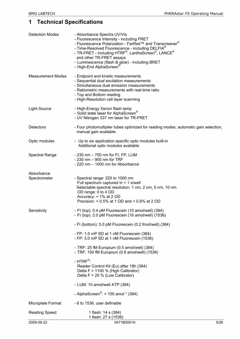
1 Technical Specifications Detection Modes - Absorbance Spectra UV/Vis - Fluorescence Intensity - including FRET - Fluorescence Polarization - FarRed™ and Transcreener® - Time-Resolved Fluorescence - including DELFIA® - TR-FRET - including HTRF®, LanthaScreen®, LANCE® and other TR-FRET assays
- Luminescence (flash & glow) - including BRET - High-End AlphaScreen®
Measurement Modes - Endpoint and kinetic measurements - Sequential dual excitation measurements - Simultaneous dual emission measurements - Ratiometric measurements with real-time ratio - Top and Bottom reading - High-Resolution cell layer scanning Light Source - High-Energy Xenon flash lamp - Solid state laser for AlphaScreen® - UV Nitrogen 337 nm laser for TR-FRET Detectors - Four photomultiplier tubes optimized for reading modes, automatic gain selection, manual gain available Optic modules - Up to six application specific optic modules built-in Additional optic modules available Spectral Range - 230 nm – 750 nm for FI, FP, LUM - 230 nm – 900 nm for TRF - 220 nm – 1000 nm for Absorbance Absorbance Spectrometer - Spectral range: 220 to 1000 nm Full spectrum captured in < 1 s/well Selectable spectral resolution: 1 nm, 2 nm, 5 nm, 10 nm OD range: 0 to 4 OD Accuracy: < 1% at 2 OD Precision: < 0.5% at 1 OD and < 0.8% at 2 OD Sensitivity - FI (top): 0.4 pM Fluorescein (10 amol/well) (384)
- FI (top): 2.0 pM Fluorescein (16 amol/well) (1536) - FI (bottom): 5.0 pM Fluorescein (0.2 fmol/well) (384) - FP: 1.0 mP SD at 1 nM Fluorescein (384) - FP: 3.0 mP SD at 1 nM Fluorescein (1536)
- TRF: 25 fM Europium (0.5 amol/well) (384) - TRF: 100 fM Europium (0.8 amol/well) (1536)
- HTRF®: Reader Control Kit (Eu) after 18h (384) Delta F > 1100 % (High Calibrator) Delta F > 25 % (Low Calibrator)
- LUM: 10 amol/well ATP (384)
- AlphaScreen®: < 100 amol * (384) Microplate Format - 6 to 1536, user definable Reading Speed 1 flash: 14 s (384) 1 flash: 27 s (1536)
PHERAstar FS Operating Manual BMG LABTECH
6/26 0471B0001A 2009-09-22
10 flashes: 38 s (384) 10 flashes: 1 min 52 s (1536) 50 flashes: 1 min 29 s (384) 50 flashes: 5 min 18 s (1536) Reagent Injectors Up to two built-in reagent injectors Injection at measurement position (6 to 384-well) Individual injection volumes for each well (3 to 350 µL) Variable injection speed (100 to 420 µL/s with a 500 µL syringe) Up to four injection events per well Reagent back flushing Gain control - Software selectable gain for F, FP, L, and AS. Height adjustment - Automatic Z-adjustment with curve monitoring Temperature Control - Incubation range from 5°C above ambient to 45°C - Temperature monitoring (with and without incubation) Plate Carrier - Auto lock microplate carrier All microplate formats up to 1536-well in all detection modes Microplates should adhere to the SBS specification and non-SBS formats should fit: (lxwxh) (mm) max: 128x86x20; min: length 124 Shaking - Double orbital, orbital and linear shaking - Programmable shake time and diameter Computer interface - USB 2.0, compatible to USB 1.1 Power requirements - 100 or 115 or 230 V, 50/60 Hz, auto ranging - Consumption: max. 300 VA Fuses - T 5A/250V for main power 100 - 240 V (use original type Wickmann only) Dimensions and weight - Height: 46 cm, width: 46 cm and depth 51 cm. Weight 50 kg max Ambient conditions - Operating temperature: 15°C to 35°C - Storage temperature: -10°C to 50°C - Humidity of atmosphere: 20 % to 80 % - Non-condensing environment. Instrument conformity - Over voltage category II; contamination class II; protection class I; Laser class I and IIIB Robotic capabilities - Easy to integrate into all existing robotic systems For medium level throughput, an optional BMG LABTECH Stacker with magazines for 50 microplates is available The fluorescence ratio associated with the HTRF® readout is a correction method developed by Cisbio international and covered by the US patent 5,527,684 and its foreign equivalents, for which Cisbio international has granted a license to BMG LABTECH. Its application is strictly limited to the use of HTRF® reagents and technology, excluding any other TR-FRET technologies. * Limit of detection < 100 amol of biotinylated and phosphorylated polypeptide (P-Tyr-100 assay kit, PerkinElmer, #6760620C), measured in white 384 small volume microplates (17 µL/well). AlphaScreen, DELFIA, and LANCE are registered trademarks of Perkin Elmer, Inc. HTRF is a registered trademark of Cisbio international. LanthaScreen is a registered trademark of Invitrogen Corp. Transcreener is a registered trademark of BellBrook Labs Specifications are subject to change without notice.

BMG LABTECH PHERAstar FS Operating Manual
2009-09-22 0471B0001A 7/26
2 Overview 2.1 Front and Right Side of PHERAstar FS
Figure 1: PHERAstar FS
Figure 2: Optic module door
Figure 3: Right side of the PHERAstar FS, showing the reagent injection system
Press the button on the grip and the optic module door can be slid aside.
Service lid for laser cartridge
Plate carrier in/out button
Optic module door
Operating lamp
Plate carrier door
Sliding Door
Magnetic Clamp Reagent
Injectors
Priming Buttons
Needle Holder
Waste Container
Holder for Compound Vessels
PHERAstar FS Operating Manual BMG LABTECH
8/26 0471B0001A 2009-09-22
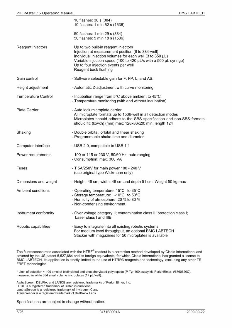
2.2 Back of PHERAstar FS
Figure 4: Back of PHERAstar FS
Figure 5: Back of PHERAstar FS
Main power on/off switch
Fan
Air inlet
Miscellaneous labeling such as serial Number, CE-marking, and voltage information
Main power on/off switch
USB connection to PC
RS-232 connection to Stacker
USB connection to PC

BMG LABTECH PHERAstar FS Operating Manual
2009-09-22 0471B0001A 9/26
3 Installation This chapter includes the initial important points that must be followed before a measurement can be performed. Please follow these steps.
When unpacking the instrument, please check to ensure that all parts are included. The shipping box should contain: PHERAstar FS instrument
• Control and evaluation software (CD ROM in a cover inside the manual) • Manual (also on CD ROM) • Power cord • USB cable • Shipment box containing:
Optic Modules 2 extra fuses-Wickmann original:
T 5A/250V for main power 100 - 240 V • Compound vessel holder type 1 and 2 • Waste container for pump priming
Call BMG LABTECH immediately if any of these items are missing.
The area designated for the instrument should be free of dust, liquids and acidic vapours. The table's surface should be flat and even. Avoid areas subject to vibrations and direct sunlight. Behind the instrument there should be a minimum distance of 10 cm.
The operator of the PHERAstar FS microplate reader is assumed to be trained in the correct operation of the instrument and the safety issues. Throughout this manual the word "you" refers to this trained operator.
Upon unpacking and positioning the reader, make sure to unlock the transport locks (section 3.1.1 and 3.1.3 below) before any power connection (section 3.2 Power and Communication Connections).
3.1 Transport Locks When the PHERAstar FS microplate reader is shipped, the transport lock for the plate carrier must be unlocked and the Optic Module transport system protection plate must be unlocked and removed.
If the PHERAstar FS has to be moved or shipped to another location, it is very important to lock and secure the two transport systems in order to avoid damage (see chapter 3.1.1 and 3.1.4 below).
3.1.1 Unlocking the Plate Carrier
The transport pin that locks the plate carrier can be accessed inside the instrument. Open the Optic Module door and you will see a silver screw for locking/unlocking the plate carrier. By hand, turn the screw counter-clockwise to unlock the pin of the plate carrier (figure 6). If the screw moves freely up and down then the plate carrier is unlocked and ready to be used. Once the PHERAstar FS has been turned on, press the In/Out button (figure 10) briefly and the plate carrier should move out.

PHERAstar FS Operating Manual BMG LABTECH
10/26 0471B0001A 2009-09-22
Figure 6: Unlocking the plate carrier
3.1.2 Locking the Plate Carrier
Upon closing the software or pushing the plate carrier in/out button for more than three seconds (figure 10), the plate carrier will move into the respective lock position. Push the screw down and turn it clockwise to lock the plate carrier (figure 7). The screw has to be tight and must not be moving as it was in the unlocked position.
Figure 7: Locking the plate carrier
Never open the plate carrier door during measuring.
3.1.3 Unlocking and Removing the Optic Module Transport System Protection Plate
Open the optic module door and unscrew the three screws and remove the (red) protection plate (figure 8). Because of a spring loading mechanism, the screws will stay connected to the protection plate. This plate is also used for offset determination of the optic module transport system. Store the protection plate in the shipment box (figure 11).
Figure 8: The optic module transport lock

BMG LABTECH PHERAstar FS Operating Manual
2009-09-22 0471B0001A 11/26
3.1.4 Inserting and Locking the Optic Module Transport System Protection Plate
Upon closing the software or pushing the plate carrier in/out button for more than three seconds (see figure 10), the Optic Module transport system will move into its respective reference and lock position. Hereafter, turn off the PHERAstar FS and you can position the red protection plate (with the spring loaded screws connected to it) in the position shown in figure 9. First position and fix (finger tight) the middle positioned screw; after that position and fix the two other screws. Figure 9: Carefully position the red protection plate and start fixing the screw in the middle position, thereafter the other two screws
Both the plate carrier transport and the optic module transport needs to be locked before moving or shipping the reader.
3.2 Power and Communication Connections
Check that the power switch on the back of the instrument is in the "OFF" position.
Inspect the voltage information on the label next to the power switch (see figure 4) to ensure that it corresponds to the local main power specifications. Also make sure the power cable is grounded. Hereafter, connect only the power cable to the instrument.
In order to make a ‘Connection check’, the Control Software needs to be installed before connecting the USB cable to the instrument. Please refer to the software manual part of this binder to install the software and how to perform a connection check.
Make sure the plate carrier and the optic module transport systems are unlocked (see chapter 3.1.1 and 3.1.3 above). Put the power switch in the “ON” position.
Connection check
Connect the USB cable to the USB port labelled “PC” located on the back of the PHERAstar FS and to the USB port on the PC. If a Stacker is included in the package, please see section 4.7 below. Once the USB cable is installed open the PHERAstar FS Control Software and perform the connection check.
Only connect a computer that corresponds to EN 60950 and UL 1950 for data processing instruments.

PHERAstar FS Operating Manual BMG LABTECH
12/26 0471B0001A 2009-09-22
4 Description of Components and Peripherals 4.1 PHERAstar FS Operating Lamp
The operating lamp (see figure 10) delivers a constant blue light when the instrument is turned on.
A flashing blue lamp (once per second) means the instrument is busy (e.g. performing a measurement, plate in/out, etc.).
A fast flashing lamp (five flashes per second) indicates that the reader has stopped for uncommon reasons.
The function of the plate carrier in/out button will be disabled during measurement and during Stacker operation!
When the plate carrier is out, the internal fan will reduce its speed, because the amount of air needed to maintain an acceptable inner environment can be acquired more easily through an open plate carrier door.
4.2 Plate Carrier In/Out Button
The plate carrier in/out button on the front (figure 10) is an easy way to get the plate carrier in and out. The plate carrier in/out button works independently from the PHERAstar FS Control Software.
Figure 10: Plate in/out button and operating lamp
Pressing the plate carrier in/out button for more than three seconds moves the transport systems of the plate carrier and the optic module to the reference positions in which they can be locked, as described in section 3.1.1 and 3.1.4 above.
4.3 PHERAstar FS Shipment Box
Figure 11: Shipment box
Optic Modules
Optic module transport lock and alignment tool
Extra bags and Allen keys
Fuses
Operating lamp
Plate in/out button
BMG LABTECH PHERAstar FS Operating Manual
2009-09-22 0471B0001A 13/26
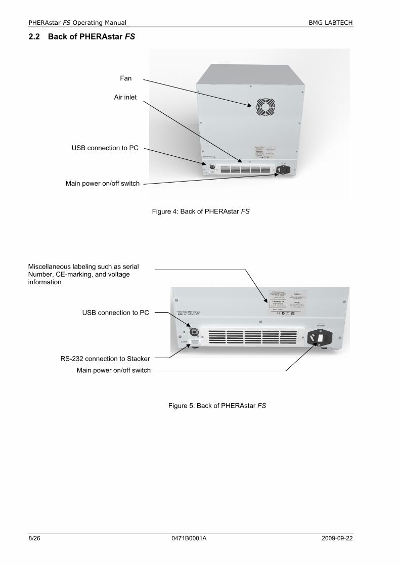
Figure 13: Hold the optic module by the handle
Figure 14: The groove of the optic module transport system
Figure 15: When installing or removing the optic module, hold the handle and move it up and out
4.4 Installing and Changing Optic Modules All PHERAstar FS readers can be equipped with six optic modules. Five optic modules can be exchanged and one optic module (Luminescence) is preinstalled.
In case of shipment or moving the PHERAstar FS, it is important to remove the optic modules from the optic module transport.
Figure 12: Optic module, front view and side view When the PHERAstar FS is in its permanent position and powered ON, the optic modules can be installed. The PHERAstar FS has five positions for optic modules. Once the optic module door has been opened the optic module transport will automatically move to a position where it can be accessed. Install the optic modules by holding it by the handle (figure 13) and then position the optic module positioning pin in the groove (figure 14 and figure 15).
Be careful not to touch any optical surfaces while handling the optic modules.
The various types of optic modules are described in more details in sections 4.5.1 to 4.5.4.
Optic module positioning pin
Excitation
Emission channel B
Handle to hold optic module
Emission channel A
Label with bar-code, measurement principle, wavelengths and batch-nr. code
PHERAstar FS Operating Manual BMG LABTECH
14/26 0471B0001A 2009-09-22
4.4.1 Built-in Barcode Reader for Optic Modules
With the built-in optic module barcode reader the PHERAstar FS will automatically detect the optic modules installed and automatically transfer the information into the optic module list. If changes have been made, they will automatically be recognized.
When no optic modules are in position, the barcode reader will detect an empty position and this information is then transferred to the optic module list.
If the optic module is a customer inter-changeable type, a message will appear informing you manually to type in wavelengths in the optic module table.
The barcode detection will be triggered by a) opening and closing the optic module door or b) performing a connection check. After turning on reader and control software this will always be done automatically.
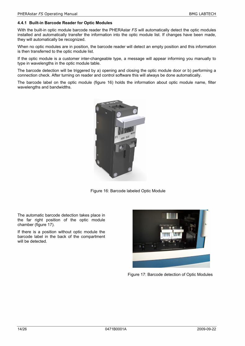
The barcode label on the optic module (figure 16) holds the information about optic module name, filter wavelengths and bandwidths.
Figure 16: Barcode labeled Optic Module
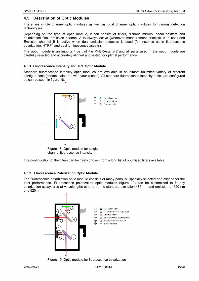
The automatic barcode detection takes place in the far right position of the optic module chamber (figure 17).
If there is a position without optic module the barcode label in the back of the compartment will be detected.
Figure 17: Barcode detection of Optic Modules
BMG LABTECH PHERAstar FS Operating Manual
2009-09-22 0471B0001A 15/26
4.5 Description of Optic Modules There are single channel optic modules as well as dual channel optic modules for various detection technologies.
Depending on the type of optic module, it can consist of filters, dichroic mirrors, beam splitters and polarization film. Emission channel A is always active (whatever measurement principle is in use) and Emission channel B is active when dual emission detection is used (for instance as in fluorescence polarization, HTRF® and dual luminescence assays).
The optic module is an important part of the PHERAstar FS and all parts used in the optic module are carefully selected and accurately aligned and tested for optimal performance.
4.5.1 Fluorescence Intensity and TRF Optic Module
Standard fluorescence intensity optic modules are available in an almost unlimited variety of different configurations (contact sales rep with your wishes). All standard fluorescence intensity optics are configured as can be seen in figure 18. Figure 18: Optic module for single channel fluorescence intensity The configuration of the filters can be freely chosen from a long list of optimized filters available.
4.5.2 Fluorescence Polarization Optic Module
The fluorescence polarization optic module consists of many parts, all specially selected and aligned for the best performance. Fluorescence polarization optic modules (figure 19) can be customized to fit any polarization assay, also at wavelengths other than the standard excitation 485 nm and emission at 520 nm and 520 nm. Figure 19: Optic module for fluorescence polarization

PHERAstar FS Operating Manual BMG LABTECH
16/26 0471B0001A 2009-09-22
4.5.3 Time-Resolved Fluorescence Optic Module, FRET and TR-FRET, for example HTRF®
The time-resolved fluorescence optic module (figure 20) is optimized for HTRF®. The beam splitters, dichoic mirror, as well as the filters, are all specially selected to give the very best performance. Figure 20: Optic module for time-resolved fluorescence, for example HTRF®
4.5.4 Luminescence Optic Modules
Luminescence assays are mostly towards light of unspecific wavelength and therefore the default optic module is an empty module. The empty module (figure 21) still needs to be there because it limits reflection and scatter.
Figure 21: Optic module for luminescence, wavelength not specified. The LUM+ Module is intended for microplate formats up to 384 wells.

BMG LABTECH PHERAstar FS Operating Manual
2009-09-22 0471B0001A 17/26
If the assay demands a specific wavelength to be measured, this can be carried out by having a filter in front of the measurement channel. And if the demand is to measure two different wavelengths, this can be carried out by including a dichroic mirror and a second filter in front of the emission channel B, for example BRET assays. (figure 22). Figure 22: Left: luminescence optic module to measure light of a specific wavelength Right: luminescence optic module to measure light of two specific wavelengths
4.5.5 AlphaScreen® Module
AlphaScreen® is a unique assay technology that measures the interaction of two molecules bioconjugated to donor and acceptor beads. When interactions occur between these molecules, the beads are brought close enough to cause a chemical reaction. Upon laser excitation at 680 nm, a singlet oxygen transfer occurs that leads to a strong light emission between 520 to 620 nm, which is directly proportional to the amount of binding (figure 23).
Figure 23: Optic Module for single channel AlphaScreen® measurement
PHERAstar FS Operating Manual BMG LABTECH
18/26 0471B0001A 2009-09-22
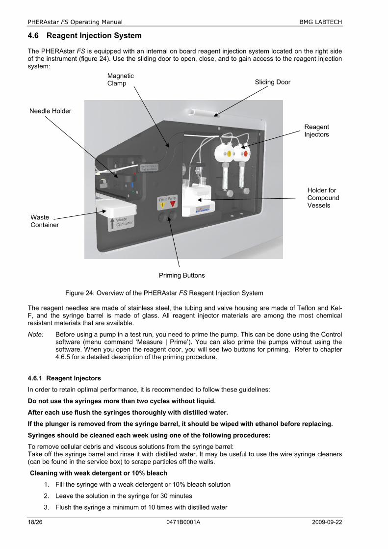
4.6 Reagent Injection System The PHERAstar FS is equipped with an internal on board reagent injection system located on the right side of the instrument (figure 24). Use the sliding door to open, close, and to gain access to the reagent injection system:
Figure 24: Overview of the PHERAstar FS Reagent Injection System The reagent needles are made of stainless steel, the tubing and valve housing are made of Teflon and Kel-F, and the syringe barrel is made of glass. All reagent injector materials are among the most chemical resistant materials that are available.
Note: Before using a pump in a test run, you need to prime the pump. This can be done using the Control software (menu command ‘Measure | Prime’). You can also prime the pumps without using the software. When you open the reagent door, you will see two buttons for priming. Refer to chapter 4.6.5 for a detailed description of the priming procedure.
4.6.1 Reagent Injectors
In order to retain optimal performance, it is recommended to follow these guidelines:
Do not use the syringes more than two cycles without liquid.
After each use flush the syringes thoroughly with distilled water.
If the plunger is removed from the syringe barrel, it should be wiped with ethanol before replacing.
Syringes should be cleaned each week using one of the following procedures:
To remove cellular debris and viscous solutions from the syringe barrel: Take off the syringe barrel and rinse it with distilled water. It may be useful to use the wire syringe cleaners (can be found in the service box) to scrape particles off the walls.
Cleaning with weak detergent or 10% bleach
1. Fill the syringe with a weak detergent or 10% bleach solution
2. Leave the solution in the syringe for 30 minutes
3. Flush the syringe a minimum of 10 times with distilled water
Sliding Door Magnetic Clamp
Reagent Injectors
Priming Buttons
Needle Holder
Waste Container
Holder for Compound Vessels

BMG LABTECH PHERAstar FS Operating Manual
2009-09-22 0471B0001A 19/26
Cleaning with acid / base (best procedure if cells are used in the syringe)
1. Fill the syringe with 0.1M NaOH and leave it in the syringe for 10 minutes.
2. Flush the syringe a minimum of 10 times with distilled water.
3. Fill the syringe with 0.1M HCl, and leave the solution in the syringe for 10 minutes.
4. Flush the syringe a minimum of 10 times with distilled water. 4.6.2 Sliding Door
The Sliding Door can be opened by pressing onto the two ends of the handle and sliding it upwards. The door will stay at the position it is released. The PHERAstar FS can not start a test run if the sliding door is in the open position. Thus always close the sliding door before starting a test run. 4.6.3 Needle Holder
The needle holder is an S-shaped device and houses one or two needles connected to the respective reagent injectors (figure 25). The arrangement of the needles and the architecture of the needle holder itself allow simultaneous injection and measurement for all detection modes except absorbance. The tubing coming from the syringe barrels are assembled together in a magnetic clamp to minimize dead volume and to guide them to the needle holder. The magnetic clamp can easily be removed by gently pulling it away from the instrument. In order to execute external priming, to exchange the needle holder or to clean the needles it is necessary to first pull away the magnetic clamp from the reader. The magnetic clamp is also equipped with a sensor which prevents the PHERAstar FS from executing a test run when the magnetic clamp and the needle holder are not properly installed.
Figure 25: Needle holder assembly
Figure 26: Waste container
The needle holder slides easily in and out off its reference position. Note that the tubing assembly, the magnetic tube clamp, and the needle holder always come as one unit. The waste container for internal priming comes as a unit but can be taken apart for cleaning as shown in figure 26. Two versions of the needle holder assembly are available. Needle holder A1 incorporates 2 needles and is used for the 96/384 square well plate format. Needle holder A2 has 1 needle and is used for the 96/384 round well plate format. Each version is recognized in the Control software by a sensor placed on the inside of the magnetic tube clamp.
Connection to the valves of the syringes
Magnetic Clamp
Needle holder with needles

PHERAstar FS Operating Manual BMG LABTECH
20/26 0471B0001A 2009-09-22
4.6.4 Holder for Compound Vessels
BMG LABTECH provides the PHERAstar FS user with two different compound holders (figure 27). They accommodate the most commonly used compound storage tubes, flasks, and even custom-made probe holders for small volumes.
Figure 27: Compound vessel holders type 1 and 2 for different storage vessels 4.6.5 Pump Priming
The reason for priming is to fill the tubing and needles of the reagent system with solution prior of executing a test run. This is necessary to avoid bubbles which could lead to false results. The priming procedure can be performed in two ways: internal or external priming: Internal priming requires that the waste container and the needle holder are installed (figure 28). The waste container must be placed underneath the needle holder and holds a total volume of max 15 ml. Once 15 ml solution volume has been reached an alert message will inform the user to take out the waste container and discard the solution. If further priming is required install the waste container again.
To start priming, place the waste container into its normal operating position, a compound solution into the compound vessel, and insert the tubing into the solution. Priming is then initiated either via the Control Software or by a double click of the respective priming buttons.
Figure 28: Internal priming conditions
Internal Priming will only start when the magnetic clamp, needle holder, and waste container are securely placed in the operating position. They are equipped with a sensor and hence priming will not start until operating position is in place.
BMG LABTECH PHERAstar FS Operating Manual
2009-09-22 0471B0001A 21/26
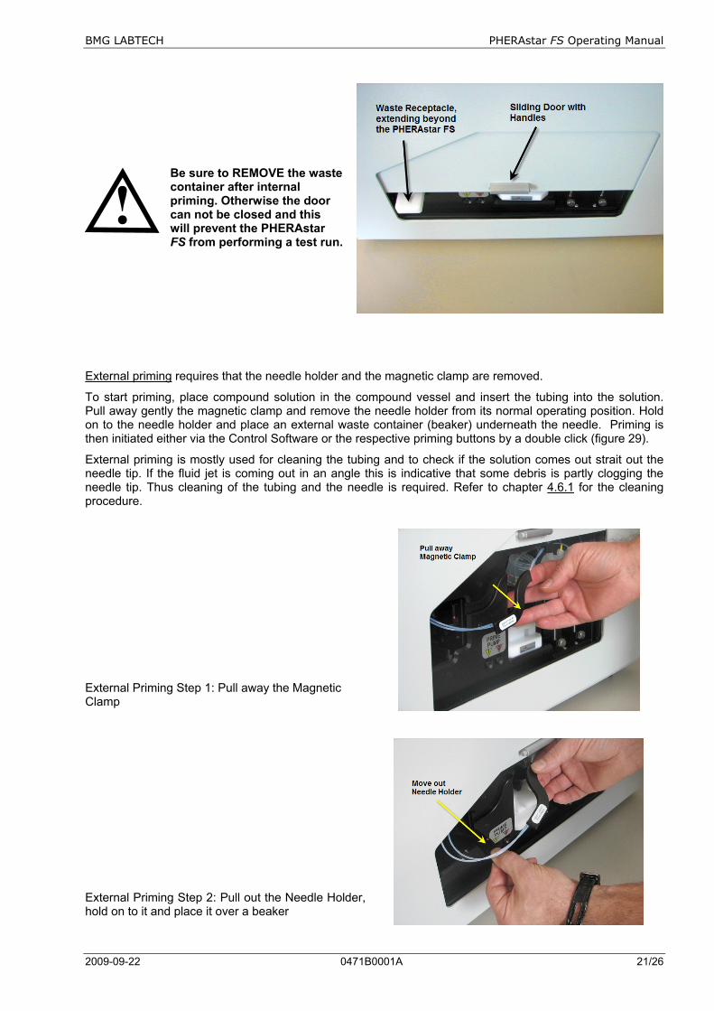
Be sure to REMOVE the waste container after internal priming. Otherwise the door can not be closed and this will prevent the PHERAstar FS from performing a test run.
External priming requires that the needle holder and the magnetic clamp are removed.
To start priming, place compound solution in the compound vessel and insert the tubing into the solution. Pull away gently the magnetic clamp and remove the needle holder from its normal operating position. Hold on to the needle holder and place an external waste container (beaker) underneath the needle. Priming is then initiated either via the Control Software or the respective priming buttons by a double click (figure 29).
External priming is mostly used for cleaning the tubing and to check if the solution comes out strait out the needle tip. If the fluid jet is coming out in an angle this is indicative that some debris is partly clogging the needle tip. Thus cleaning of the tubing and the needle is required. Refer to chapter 4.6.1 for the cleaning procedure.
External Priming Step 1: Pull away the Magnetic Clamp
External Priming Step 2: Pull out the Needle Holder, hold on to it and place it over a beaker

PHERAstar FS Operating Manual BMG LABTECH
22/26 0471B0001A 2009-09-22
External Priming Step 3: Double click on a priming button to start external priming
Figure 29: Steps for external priming End external priming by inserting the needle holder and placing the magnetic clamp to their respective operating positions. Close the sliding door for executing a measurement run. 4.7 PHERAstar FS - Stacker Connection On the back of the PHERAstar FS there are 2 connectors, one for the PC and one for the Stacker.
The respective cables are provided with the instruments. The USB cable will connect only the PC to the PHERAstar FS (‘Connection to PC‘) whereas the male-to-female RS232 cable (included with the Stacker) will connect only the PHERAstar FS to the Stacker.
If a Stacker is connected with a cable, it will automatically be detected by the PHERAstar FS and this independently of the Stacker being turned on or off.
The PHERAstar FS can be operated as a stand-alone plate reader also when connected to a Stacker, because the plate carrier can be reached through the opening of the Stacker.
Whenever the reader is connected to a Stacker (figure 30) both instruments must be turned on. If you want to use the reader with single plates, simply remove the magazines and the plate carrier of the reader can be accessed and used by pressing Plate in/ Plate out button or by using the control software.
Figure 30: PHERAstar FS with Stacker
BMG LABTECH PHERAstar FS Operating Manual
2009-09-22 0471B0001A 23/26
4.8 Automatic Height Sensor The PHERAstar FS measures the focusing in steps of 0.1 mm for both top and bottom reading modes. To make the focus alignment (also known as Z-focus) as fast as possible, an initial plate height monitoring takes place upon every plate-in command. For more information on the Z-focus see the PHERAstar FS quick guide and the software manual.
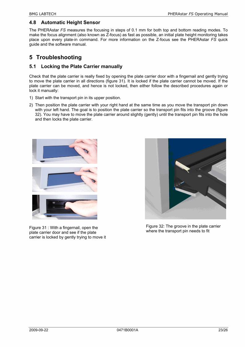
5 Troubleshooting 5.1 Locking the Plate Carrier manually Check that the plate carrier is really fixed by opening the plate carrier door with a fingernail and gently trying to move the plate carrier in all directions (figure 31). It is locked if the plate carrier cannot be moved. If the plate carrier can be moved, and hence is not locked, then either follow the described procedures again or lock it manually:
1) Start with the transport pin in its upper position.
2) Then position the plate carrier with your right hand at the same time as you move the transport pin down with your left hand. The goal is to position the plate carrier so the transport pin fits into the groove (figure 32). You may have to move the plate carrier around slightly (gently) until the transport pin fits into the hole and then locks the plate carrier.
Figure 31 : With a fingernail, open the plate carrier door and see if the plate carrier is locked by gently trying to move it
Figure 32: The groove in the plate carrier where the transport pin needs to fit

PHERAstar FS Operating Manual BMG LABTECH
24/26 0471B0001A 2009-09-22
5.2 Transport System Offset The offset values are unique for each instrument and are stored in the PHERAstar FS chipset (EEPROM) before shipment. No further actions are needed. However, wrong definitions of a microplate format can lead to cross-talk.
Increased cross-talk and drift (in a 1536-well plate with same fluorescein concentration) is an indication of incorrect or inaccurate dimensions of the microplate definition. Contact BMG LABTECH service personnel for procedures.
Figure 33: The various reader offsets; contact BMG LABTECH trained service personnel for procedures The PHERAstar FS has an automatic plate carrier offset determination which uses two small dots for positioning determination (figure 34). For more details, please contact BMG LABTECH service personnel as the determination should be carried out only by trained personnel.
Figure 34: Plate carrier adjustment dots
BMG LABTECH PHERAstar FS Operating Manual
2009-09-22 0471B0001A 25/26
6 Instrument Disinfection
If shipment of the PHERAstar FS is needed it is important to disinfect the PHERAstar FS and complete the disinfection certificate. If a disinfection certificate does not follow the reader the instrument shipment may be held by the customs authorities.
Please follow the instructions carefully for a successful disinfection of the PHERAstar FS.
All parts of the instrument, which have the possibility of contacting patient sera or positive samples, have to be handled as if they are hazardous. For this reason, it is recommended that gloves be worn while maintaining or working with the instrument.
It is very important that the instrument is thoroughly disinfected before maintenance or before removing the instrument from the laboratory. Be sure that the instrument is disinfected before you send it to your distributor or to the producer. For safety reasons, you have to fill out the Disinfection Certificate, or the instrument may not be accepted by the service centre or by customs authorities.
Use suitable disinfectants, e.g. Alcohol (70%)
Authorized personnel wearing disposable gloves and protective glasses and clothing should only perform the disinfection procedure. The location should be well ventilated.
Please note that formaldehyde may have influence on measurement results.
Disinfection Steps
1. Disconnect the instrument from the main power supply.
2. Remove the USB cable from the connector.
3. Clean all outside surfaces of the instrument carefully with cotton wool, which has been soaked in disinfecting solution.
4. Place the instrument in a large plastic bag along with the cotton wool that has been soaked in disinfection solution. Ensure that the wool does not touch the instrument.
5. Close and seal the bag.
6. Keep the instrument in the plastic bag for at least 24 hours.
7. After the disinfection time has lapsed, remove the instrument from the plastic bag and clean all outside surfaces of the instrument with cotton wool that has been soaked in alcohol solution.
8. Repeat the procedure for disinfection on any accessories, which will be returned with the instrument.
9. Complete the Disinfection Certificate.

Disinfection Certification This instrument and its inventory have never been in contact with any dangerous biological material, or if so, the instrument and its inventory have been disinfected according to the instructions given in the Operating Manual. Name: ________________________________________________ Firm: ________________________________________________ ________________________________________________ ________________________________________________ ________________________________________________ Date, Signature: ________________________