0401 - e120 - civil codes and inspection - 03 - site ... · training course on civil/structural...
TRANSCRIPT

Training Course onTraining Course onCivil/Structural Codes and Inspectionp
BMA Engineering, Inc.
1BMA Engineering, Inc. – 3000
Overall OutlineOverall Outline
1000. Introduction
2000. Federal Regulations, Guides, and Reports
3000. Site Investigation
4000. Loads, Load Factors, and Load Combinations
5000. Concrete Structures and Construction
6000. Steel Structures and Construction
7000. General Construction Methods
8000. Exams and Course Evaluation
9000. References and Sources
2BMA Engineering, Inc. – 3000
3000 Site Investigation3000. Site Investigation
• Objective and Scope– Present and discuss
• Site investigation for foundations of nuclear power plants
• Laboratory investigations and soil sampling of soils and rocks for engineering analysis and design of nuclear power plants
BMA Engineering, Inc. – 3000 3
3000 Site Investigation3000. Site Investigation
• Site Investigation for Foundations of N l P Pl t3100 Nuclear Power Plants
• Laboratory Investigations and Soil Sampling of Soils and Rocks for
3200Sampling of Soils and Rocks for Engineering Analysis and Design of Nuclear Power Plants
BMA Engineering, Inc. – 3000 4

3I00. Site Investigation for Foundations of Nuclear Power Plants
• Site investigation for foundations of nuclear power plants is based on Regulatory Guide p p g y1.132 [Revision 2 October 2003]
• Purpose• Purpose– To describe methods for conducting field investigations to acquire the needed geotechnical data for defining subsurface conditions and identifying potential geologic hazards at the site in order to design nuclear power plant foundations for safety and performance
BMA Engineering, Inc. – 3000 5
3I00. Site Investigation for Foundations of Nuclear Power Plants
• Types of Data to be Acquired
Lit t S h d R i• Literature Search and Reconnaissance
• Detailed Site Investigationg
• Groundwater Investigations
• Construction Mapping
• Support Functions
BMA Engineering, Inc. – 3000 6
3I00. Site Investigation for Foundations of Nuclear Power Plants
• Types of Data to be Acquired– Geological Conditionsg
– Engineering Properties of Soils and Rocks
Groundwater Conditions– Groundwater Conditions
– Man‐Induced Conditions
– Cultural and Environmental
– Related Considerations
BMA Engineering, Inc. – 3000 7
3I00. Site Investigation for Foundations of Nuclear Power Plants
• Types of Data to be Acquired
1 G l i l C diti1. Geological Conditions
• Types and structure of soils and rocks at the surface and in the b fsubsurface
• Degree and extent of weathering • Petrological characteristics (structure, texture, and composition)et o og ca c a acte st cs (st uctu e, te tu e, a d co pos t o )• Potential hazards (faulting, landslides, erosion, deposition)• Caverns formed by dissolution or mining activity• Ground subsidence• Soil shrinking, swelling, and liquefaction potential• Characteristics and orientation of bedding foliations or jointing
BMA Engineering, Inc. – 3000 8
• Characteristics and orientation of bedding, foliations, or jointing

3I00. Site Investigation for Foundations of Nuclear Power Plants
• Types of Data to be Acquired
2 Engineering Properties of Soils and Rocks2. Engineering Properties of Soils and Rocks• Density and seismic velocities• Parameters of strength elasticity and plasticity• Parameters of strength, elasticity, and plasticity• Details are covered in Section 3200 [RG 1.138]
3 Groundwater Conditions3. Groundwater Conditions• Groundwater conditions at the site that include:• Groundwater levels• Groundwater levels• Thickness of aquifers and confining beds• Groundwater flow patterns
BMA Engineering, Inc. – 3000 9
p• Transmissivities and storage coefficients
3I00. Site Investigation for Foundations of Nuclear Power Plants
• Types of Data to be Acquired
4. Man‐Induced Conditions
• Existing construction and infrastructure in the site• Existing construction and infrastructure in the site• Dams or reservoirs whose locations may cause a flooding hazard or produce loading effects at the site
• Mining or oil and gas production and other fluid extraction or injection
• Presence of former industrial sites, underground storage tanks, or , g g ,landfills
• potential for hazardous, toxic, or radioactive waste
BMA Engineering, Inc. – 3000 10
3I00. Site Investigation for Foundations of Nuclear Power Plants
• Types of Data to be Acquired
l l d i l id i5. Cultural and Environmental Considerations
• Compliance with Archaeological Resources Protection Act of 1979 and the Native American Graves Protection and Repatriation Act of 1990
• Compliance with Clean Water Act (33 U.S.C. 1344)
6. Related Considerations
• Guidance on seismicity and related seismic data and historical recordsGuidance on seismicity and related seismic data and historical records in Regulatory Guide 1.165
• Guidance on vibratory ground motion resulting from earthquakes
BMA Engineering, Inc. – 3000 11
3I00. Site Investigation for Foundations of Nuclear Power Plants
• Literature Search and Reconnaissance
Existing Literature and Field
R i Site SuitabilityMap Studies Reconnaissance y
BMA Engineering, Inc. – 3000 12

3I00. Site Investigation for Foundations of Nuclear Power Plants
Lit t S h d R i• Literature Search and Reconnaissance1. Existing Literature and Map Studies• Acquire existing knowledge of geological and other site conditions• Understanding of the regional geology• Published material and existing maps of topography, geology, hydrology, and soils
• Studying aerial photographs and other remote sensing imageryy g p g p g g y• Regional strain rates of Global Positioning System (GPS), if available• Plans held by utilities should be consulted to locate services such as
t l t i i ti li li twater, gas, electric, communication lines, power lines, access routes• Records on mining, oil, gas, and water wells, and oil exploration• Records on cultural resources
BMA Engineering, Inc. – 3000 13
3I00. Site Investigation for Foundations of Nuclear Power Plants
• Literature Search and Reconnaissance2. Field Reconnaissancee d eco a ssa ce• Perform a preliminary field reconnaissance of the site and its surrounding area using an appropriate topographic or geologic map for• special geologic features and conditions such as landslides, faults and past seismic activityand past seismic activity
• potential borrow areas, quarry sites, or water impoundment areas
3 Site Suitability3. Site Suitability• Make a preliminary determination of site suitability and formulate a plan for detailed site investigations
BMA Engineering, Inc. – 3000 14
plan for detailed site investigations
3I00. Site Investigation for Foundations of Nuclear Power Plants
Detailed Site Investigations
Site Information To Be Developed
Detailed Site Investigations
Topographic
Site Information To Be Developed
Topographic and Geologic
MapsPlot Plans Boring Logs
Maps
Geologic Profiles
Geophysical Data
BMA Engineering, Inc. – 3000 15
Detailed Site InvestigationsDetailed Site Investigations
Surface Investigations
Subsurface Investigations
Geophysical Investigations
Logs of Subsurface Investigations
BMA Engineering, Inc. – 3000 16

Detailed Site InvestigationsDetailed Site InvestigationsSurface Investigations
• Surface Investigations– Conducting detailed surface geological and g g ggeotechnical engineering investigations over the site area to assess all relevant soil and rock characteristics
– Preparing topographic maps at suitable scales toPreparing topographic maps at suitable scales to• Plot geologic, structural, and engineering details at the site andsite and
• Note related conditions in surrounding areas (borrow areas, quarries, or access roads), q , )
BMA Engineering, Inc. – 3000 17
Detailed Site InvestigationsDetailed Site InvestigationsSurface Investigations
• Surface Investigations (Cont…)– Features to be identified on the Mapp
• Hydrogeologic, and surface geologic features
• Rock outcrops, soil conditions, evidence of pastRock outcrops, soil conditions, evidence of past landslides or soil liquefaction, faults, fracture patterns, geologic contacts, and lineaments
• Local engineering geology and soil conditions
• Surface‐water features (rivers, streams, or lakes, surface drainage channels, ponds, springs)
BMA Engineering, Inc. – 3000 18
Detailed Site InvestigationsDetailed Site InvestigationsSubsurface Investigations
• Objectives of Subsurface Investigations– To expand the knowledge of the three‐p gdimensional distribution of both geologic conditions (soils, rocks, structure) and engineering ( , , ) g gproperties at the site and at borrow areas
– To gain further information on possible safetyTo gain further information on possible safety hazards such as underground cavities, hidden faults or contactsfaults, or contacts
BMA Engineering, Inc. – 3000 19
Subsurface InvestigationsSubsurface Investigations
In Situ Testing
Borings and Exploratory Excavations
Sampling Transportation d St f
Testing
Excavations and Storage of Samples
BMA Engineering, Inc. – 3000 20

Detailed Site InvestigationsDetailed Site InvestigationsSubsurface Investigations
• Borings and Exploratory Excavations– Boreholes are effective means of obtaining gdetailed information on geologic formations (identifying and classifying soil types, Obtaining ( y g y g yp , ggroundwater data) in the subsurface and their engineering properties beneath planned g g p p pfoundations
– Excavations in the form of test pits trenches andExcavations in the form of test pits, trenches, and exploratory shafts may be used to complement the borehole explorationthe borehole exploration
BMA Engineering, Inc. – 3000 21
Detailed Site InvestigationsDetailed Site InvestigationsSubsurface Investigations
Methods of Borings and Exploratory Excavations
Pits, trenches,
h f lAuger boring Hollow stem
auger boring Wash boringshafts, tunnels
g g auger boring g
Continuous
Rotary drilling Percussion drilling Cable drilling
Continuous sampling or displacement
BoringBoring
• Procedure, applicability and limitations are available in Appendix C of RG 1.132
BMA Engineering, Inc. – 3000 22
Detailed Site InvestigationsDetailed Site InvestigationsSubsurface Investigations
• Examples of Common Methods for Borings
Auger BoringsAuger Borings• Provide disturbed samples suitable for determining soil type, Atterberg limits, and Proctor compaction testingyp , g , p g
• Most useful for preliminary soil type investigations, advancing holes for other sampling methods, determining depth to top of bedrock and installingdepth to top of bedrock, and installing
Wash BoringsC bi ti f t i l ti d l i f th• Combination of water circulation and a loosening of the soils using various types of bits
• Preferred method for obtaining good quality samples or
BMA Engineering, Inc. – 3000 23
obtaining reliable measurements of penetration resistance
Detailed Site InvestigationsDetailed Site InvestigationsSubsurface Investigations
• Borings and Exploratory Excavations– Each safety‐related structure should have at least yone continuously sampled boring
– Spacing and depth of borings for a site of safety‐Spacing and depth of borings for a site of safetyrelated structures should be chosen according to the complexity of subsurface conditions andthe complexity of subsurface conditions and foundation requirements
Appendix D of RG 1 132 provides guidelines on– Appendix D of RG 1.132 provides guidelines on spacing of borings and minimum depth of penetration for different structurespenetration for different structures
BMA Engineering, Inc. – 3000 24

Detailed Site InvestigationsDetailed Site InvestigationsSubsurface Investigations
• Spacing For Boring of Safety‐related Foundations– At least one boring should be at the location of every safety‐related structureevery safety related structure
– Where variable conditions are found, spacing should be smallershould be smaller
– Where cavities or other discontinuities may occur, i h ld b ll h t d t t hspacing should be small enough to detect such
features
BMA Engineering, Inc. – 3000 25
Detailed Site InvestigationsDetailed Site InvestigationsSubsurface Investigations
• Depth of Penetration For Boring of Safety‐related Foundations– Should extend at least 10 m (33 ft) below the lowest part of the foundationlowest part of the foundation
– If competent rock is encountered at lesser depths than borings should penetrate to the greatestthan , borings should penetrate to the greatest depth where discontinuities or zones of weakness or alteration can affect foundations and shouldor alteration can affect foundations and should penetrate or at least 6 m (20 ft) into sound rock
BMA Engineering, Inc. – 3000 26
Detailed Site InvestigationsDetailed Site InvestigationsSubsurface Investigations
• Depth of Penetration For Boring of Safety‐related Foundations– Depth should be sufficient to define the site geology and to sample all materials that maygeology and to sample all materials that may swell, consolidate, be unstable under earthquake loading, or whose physical properties would affectloading, or whose physical properties would affect foundation behavior or stability
Maximum depth (where soils are very thick)– Maximum depth (where soils are very thick) should be where vertical stress change is less than 10% of the effective in situ overburden stress
BMA Engineering, Inc. – 3000 27
10% of the effective in situ overburden stress
Detailed Site InvestigationsDetailed Site InvestigationsSubsurface Investigations
B i S i d D th f P t ti• Boring Spacing and Depth of PenetrationBuildings, Retaining Walls, Concrete Dams
• Spacing• At least one boring beneath every safety‐related structure• at least one boring per 900 m2 (10,000 ft2)• One boring per 30 m (100 ft) for essentially linear structures• A number of borings along the periphery and at cornersA number of borings along the periphery and at corners
• Minimum Depth of Penetration• At least one‐fourth of the borings and a minimum of one boring per structure to
d k d hpenetrate into sound rock or to maximum depth• Others to a depth below foundation elevation equal to the width of structure or to a depth equal to the foundation depth below the original ground surface, whichever is greater
BMA Engineering, Inc. – 3000 28
whichever is greater

Detailed Site InvestigationsDetailed Site InvestigationsSubsurface Investigations
B i S i d D th f P t ti• Boring Spacing and Depth of Penetration
E th D Dik L E b k tEarth Dams, Dikes, Levees, Embankments
• Spacing• One per 30 m (100 ft) along axis of structure and at critical locations perpendicular to the axis to establish geological sections with groundwater conditions for analysiswith groundwater conditions for analysis
•Minimum Depth of Penetration• One per 60 m (200 ft) to maximum depthp ( ) p• Others should penetrate all strata whose properties would affect the performance of the foundation
BMA Engineering, Inc. – 3000 29
Detailed Site InvestigationsDetailed Site InvestigationsSubsurface Investigations
B i S i d D th f P t ti• Boring Spacing and Depth of PenetrationDeep Cuts, Canalsp
• Spacing• One per 30 m (100 ft) along axis of structure and at criticalOne per 30 m (100 ft) along axis of structure and at critical locations perpendicular to the axis to establish geological sections with groundwater conditions for analysis
Minim m Depth of Penetration•Minimum Depth of Penetration• One per 60 m (200 ft) to sound rock or to maximum depth• Others to cut depth or to below the lowest slope failure zone• Others to cut depth or to below the lowest slope failure zone • Penetrate previous strata below which groundwater may influence stability
BMA Engineering, Inc. – 3000 30
Detailed Site InvestigationsDetailed Site InvestigationsSubsurface Investigations
• Boring Spacing and Depth of PenetrationPipelines
• SpacingOne per 30 m (100 ft) for buried pipelines
Pipelines
– One per 30 m (100 ft) for buried pipelines– At least one boring for each footing for pipelines above ground
• Minimum Depth of Penetrationp– For buried pipelines, one of every three to penetrate sound rock
or to maximum depth– Others to 5 times pipe diameters below the elevation– Others to 5 times pipe diameters below the elevation– For pipelines above ground, depths as for foundation structures
BMA Engineering, Inc. – 3000 31
Detailed Site InvestigationsDetailed Site InvestigationsSubsurface Investigations
• Boring Spacing and Depth of PenetrationTunnels
• Spacing
Tunnels
– One per 30 m (100 ft)– May vary for rock tunnels, depending on rock typeMi i D th f P t ti• Minimum Depth of Penetration– One per 60 m (200 ft) to penetrate sound rock or to maximum depthmaximum depth
– Others to 5 times the tunnel diameters below the elevation
BMA Engineering, Inc. – 3000 32

Detailed Site InvestigationsDetailed Site InvestigationsSubsurface Investigations
• Boring Spacing and Depth of PenetrationReservoirs Impoundments
• Spacing
Reservoirs, Impoundments
– As per dams or dikes– Spacing varies with largest concentration near control structures coverage decreasing with distancestructures coverage decreasing with distance
• Minimum Depth of Penetration– At least one‐fourth to penetrate that portion of theAt least one fourth to penetrate that portion of the saturation zone that may influence seepage conditions or stabilityOthers to a depth of 7 5 m (25 ft) below reservoir
BMA Engineering, Inc. – 3000 33
– Others to a depth of 7.5 m (25 ft) below reservoir
Detailed Site InvestigationsDetailed Site InvestigationsSubsurface Investigations
• Borings and Exploratory Excavations – The borehole should be protected by drilling mud p y gor casing and the top of the hole should be protected by a suitable surface casing as neededp y g
– After use, each borehole should be grouted to prevent vertical movement of groundwaterprevent vertical movement of groundwater through the borehole
Borehole elevation should be measured to the– Borehole elevation should be measured to the nearest 3 cm (0.1 ft) and correlated to the elevation datum used for the siteelevation datum used for the site
BMA Engineering, Inc. – 3000 34
Detailed Site InvestigationsDetailed Site InvestigationsSubsurface Investigations
• Borings and Exploratory Excavations– Field inspector duties during drillingp g g
• Observing and describing drilling tools and procedures, geologic materials and their discontinuities, and drilling activities and groundwater measurements
• Selecting and preserving samples and performing field tests on core samples
• Photographing site conditions and cores
• Completing the drilling log and/or entering information into a cataloging system
• Recording information and data from in‐situ tests.
BMA Engineering, Inc. – 3000 35
Detailed Site InvestigationsDetailed Site InvestigationsSubsurface Investigations
• Sampling– Sampling of soils in boreholes should include, as a p g ,minimum, the recovery of samples at regular intervals and at changes in materialsg
– Alternating split spoon and undisturbed samples with depth is recommendedwith depth is recommended
– Color photographs of all cores should be taken soon after removal from the borehole tosoon after removal from the borehole to document the condition of the soils at the time of drillingdrilling
BMA Engineering, Inc. – 3000 36

Detailed Site InvestigationsDetailed Site InvestigationsSubsurface Investigations
H d Fi d i Hydraulic piston F i O d i
Methods of Sampling Soil or Rock
Hand cut or cylindrical sample
Fixed‐piston Sampler
Hydraulic piston sampler (Osterberg
Sampler)
Free‐piston Sampler
Open drive Sampler
Swedish Foil Sampler
Split‐barrel or splitspoon sampler Auger sampling Rotary core barrel Denison sampler
Shot core boring (Calyx)
Oriented integral sampling
Wash sampling or cuttings sampling
Submersible vibratory (Vibracore) sampler
Underwater piston corer
Gravity corer• Procedure, applicability and limitations are
available in Appendix C of RG 1.132
BMA Engineering, Inc. – 3000 37
Detailed Site InvestigationsDetailed Site InvestigationsSubsurface Investigations
S li
Sampling Rock
• Sampling
Sampling Rock
• Core samples are needed to observe and define rock composition, structure, bedding, jointing, fracturing, and weathering
• Rocks should be sampled to a depth below which rockRocks should be sampled to a depth below which rock characteristics do not influence foundation performance
• The nature, geometry, and spacing of any discontinuities or l h ld b d t i d b fanomalous zones should be determined by means of
suitable logging or in situ observation methods
BMA Engineering, Inc. – 3000 38
Detailed Site InvestigationsDetailed Site InvestigationsSubsurface Investigations
S li• SamplingSampling Coarse‐Grained Soils
– Samples should be obtained when changes in materials occur and at regular intervals in depth
p g
materials occur and at regular intervals in depth of
• 1 5 m (5 ft) until a depth of 15 m (50 ft) below• 1.5 m (5 ft) until a depth of 15 m (50 ft) below foundation level
• 3 m (10 ft) beyond 15 m (50 ft) below foundation level3 m (10 ft) beyond 15 m (50 ft) below foundation level
– One or more borings for each major structure should be continuously sampled
BMA Engineering, Inc. – 3000 39
should be continuously sampled
Detailed Site InvestigationsDetailed Site InvestigationsSubsurface Investigations
S li• SamplingSampling Coarse‐Grained Soils
– Split spoon sampling and standard penetration tests should be used to define the soil profile and
p g
tests should be used to define the soil profile and variations of soil conditions
When coarse grained soils contain gravels and– When coarse‐grained soils contain gravels and boulders, excavations like trenches or pits into the zones of interest may be required and percentagezones of interest may be required and percentage of boulders should be estimated
BMA Engineering, Inc. – 3000 40

Detailed Site InvestigationsDetailed Site InvestigationsSubsurface Investigations
• Sampling
Sampling Moderately Compressible or NormallySampling Moderately Compressible or Normally Consolidated Clay or Clayey Soils
– Undisturbed samples should be obtained and continuous throughout the compressible strata in one or more principal borings for each major structure
– Borings used for undisturbed sampling of soils should be at least 7.6 cm (3 in.) in diameter( )
BMA Engineering, Inc. – 3000 41
Soil SamplingSoil Sampling
• Principles, equipments, procedures, and limitations for obtaining, handling, and g, g,preserving soil samples
• Disturbed samples are primarily used for• Disturbed samples are primarily used for moisture content, Atterberg limits, specific gravity, sieve analysis or grain‐size distribution, and compaction characteristics
• Undisturbed samples are useful for strength, compressibility and permeability testscompressibility, and permeability tests
BMA Engineering, Inc. – 3000 42
Soil SamplingSoil Sampling
• Parameters that may affect sample disturbance duringg
samplingA ti C– Area ratio Ca
– frictionInside clearance
ratio Ci– Outside clearanceOutside clearance
ratio Co
BMA Engineering, Inc. – 3000 43
Soil SamplingSoil Sampling
• Parameters that may affect sample disturbance during sampling (Cont …)g p g ( )– Length‐to‐diameter ratio: should be 5‐10 for cohesionless soils and 10‐20 for cohesive soilscohesionless soils and 10 20 for cohesive soils
– Method of advancing the sample tube
St li f ( t d illi d i )– Stress relief (water, drilling mud, casing)
– Sample recovery
BMA Engineering, Inc. – 3000 44

Soil SamplingSoil Sampling
• Disturbance after sampling may be due to: – change of water content, g ,
– moisture migration within sample,
Penetration of voids by wax used to seal sample– Penetration of voids by wax used to seal sample
– vibration due to sample transportation,
– freezing of silt or clay samples,
– chemical reaction between sample and tube, p ,
– disturbance due to extruding sample from tube
BMA Engineering, Inc. – 3000 45
Soil SamplingSoil Sampling
• Selection of sampling apparatus p g ppto obtain undisturbed samplesundisturbed samples– Two basic types of sampling apparatus:sampling apparatus: push‐tube samplers and rotary coreand rotary core‐barrel samplers
BMA Engineering, Inc. – 3000 46
Soil SamplingSoil Sampling
• Push‐tube samplers include – open‐tube samplers and p p
– piston samplers (free‐, fixed‐, and retractable‐piston samplers)piston samplers)
• Rotary core‐barrel samplers include – single‐tube core‐barrel samplers,
– double‐tube core‐barrel samplers, and p ,
– triple‐tube core‐barrel samplers
BMA Engineering, Inc. – 3000 47
Soil SamplingSoil Sampling
• Sampling apparatus to obtain undisturbed samplesp– Undisturbed samples of medium to fine sands can be obtained by hand trimming or in situ freezingbe obtained by hand trimming or in situ freezing and core drilling
Fixed piston samplers in a mudded borehole can– Fixed‐piston samplers in a mudded borehole can be used for sand below the water table
Th l di t h ld d i ti th– The sample diameter should exceed six times the size of the largest particle size
BMA Engineering, Inc. – 3000 48

Drill Rigs and AppurtenantDrill Rigs and Appurtenant
• Drill rigs elements– Power source
– Fluid pump and accessoriesaccessories
– Drill head
i– Hoists
– Derrick
– Mounting platform
– Ancillary equipmentAncillary equipment
BMA Engineering, Inc. – 3000 49
Drill Rigs and AppurtenantDrill Rigs and Appurtenant
BMA Engineering, Inc. – 3000 50
Drill Rigs and AppurtenantDrill Rigs and Appurtenant
• Types of drills– Drills for wash borings
• Include chopping,Include chopping, jetting and washing
– Chunk drillsChunk drills• Up‐and‐down hammeringg
BMA Engineering, Inc. – 3000 51
Drill Rigs and AppurtenantDrill Rigs and Appurtenant
• Types of drills (cont..) – Rotary drillsy
• Rotary action coupled with downward pressure plus cleaning action of drilling fluid
• Used for drilling, sampling, bucket‐auger drilling, and reverse‐circulation drilling
• Truck mounted: can drill 200 to 1000 ft
• Hydraulic mounted: can drill 500 to 2500 ft
BMA Engineering, Inc. – 3000 52

Drill Rigs and AppurtenantDrill Rigs and Appurtenant
• Types of drills (cont..)– Hammer drills
• Either driving or rotating and driving a drill
• Borehole diameter range from 4 to 16 inchesBorehole diameter range from 4 to 16 inches
• Becker hammer drill: used in sand, gravel , and boulders
• Becker CRS drill: drill is hammered and rotated
• Electric reamer system: rotation plus percussiony p p
– Auger drills• Rotary drilling with other types of augers• Rotary drilling with other types of augers
BMA Engineering, Inc. – 3000 53
Drill Rigs and AppurtenantDrill Rigs and Appurtenant
BMA Engineering, Inc. – 3000 54
Drill Rigs and AppurtenantDrill Rigs and Appurtenant
BMA Engineering, Inc. – 3000 55
Drill Rigs and AppurtenantDrill Rigs and Appurtenant
• Accessories and appurtenant equipmentpp q p– Standard nomenclature
Drill rods– Drill rods
– Drill bits
– Casing
BMA Engineering, Inc. – 3000 56

Drill Rigs and AppurtenantDrill Rigs and Appurtenant
• Accessories and appurtenant pp
equipment (Cont…)P t bl– Portable sumps
– Surface casing
– Augers
– Bailers and sand pumpsBailers and sand pumps
– Fishing tools
Mi ll h d t l– Miscellaneous hand tools
BMA Engineering, Inc. – 3000 57
Drilling FluidDrilling Fluid
• Purpose: – cleaning and transporting the cuttingg p g g
– Cooling and lubricating the drill bit and rods
T f d illi fl id• Types of drilling fluid– Compressed air
– Foam
– Clear waterClear water
– Water‐based muds
BMA Engineering, Inc. – 3000 58
Drilling FluidDrilling Fluid
• Properties of water‐based muds– Viscosity
Density– Density
– Gel strength
– Filtration
BMA Engineering, Inc. – 3000 59
Drilling FluidDrilling Fluid
BMA Engineering, Inc. – 3000 60

Drilling FluidDrilling Fluid
• Mixing and handling– Affected by water quality and method of y q ymixing
BMA Engineering, Inc. – 3000 61
Drilling FluidDrilling Fluid
• Drilling and sampling problemsp– Hole stabilization
• Coving squeezing groundCoving, squeezing ground
– Control of hydrostatic pressurepressure
– Improved sample recovery
– Enhanced pump capacity
– Solids recirculation
BMA Engineering, Inc. – 3000 62
Drilling FluidDrilling Fluid
• Limitations and precautions– Hydraulic fracturingy g
• In earth dam embankments when drill fluid is used in the fill
– Formation permeability
– Environmental drilling– Environmental drilling
– Effect on strength testingh ld b f ll d f d ll d• Should be carefully inspected for drilling mud infiltration
BMA Engineering, Inc. – 3000 63
Detailed Site InvestigationsDetailed Site InvestigationsSubsurface Investigations
• Undisturbed Samples– Undisturbed samples are obtained using one of p gtwo methods: push samplers and rotary samplers
– These methods permit obtaining samples forThese methods permit obtaining samples for shear strength, consolidation, permeability, and density testsdensity tests
– Example push samplers: Hvorslev fixed‐ position sampler and Osterberg hydraulic piston samplersampler and Osterberg hydraulic piston sampler
– Example rotary samplers: Denison barrel and Pi h S lPitcher Sampler
BMA Engineering, Inc. – 3000 64

Detailed Site InvestigationsDetailed Site InvestigationsSubsurface Investigations
• Undisturbed Samples– Rotary samplers are more disruptive to soil y p pstructure
– Undisturbed samples can be sliced to permitUndisturbed samples can be sliced to permit detailed study of subsoil stratification
Can obtain undisturbed samples of clays and silts– Can obtain undisturbed samples of clays and silts and nearly undisturbed samples of some sands
C i i i di b d– Care is necessary in transporting undisturbed samples (sands and silts disturbance of vibration)
BMA Engineering, Inc. – 3000 65
Detailed Site InvestigationsDetailed Site InvestigationsSubsurface Investigations
• Undisturbed Samples of Cohesionless Soil– To prevent handling disturbance in cohesionless p gsoil, obtain 3 inch Shelby tube samples, drain them, and freeze them before transportation, p
– Chemical stabilization or impregnation can be used as to sample and preserve the naturalused as to sample and preserve the natural structure of cohesionless granular material
High quality block samples can be obtained by– High quality block samples can be obtained by means of hand‐carving oversized blocks of soil or hand advancing of thin walled tubeshand‐advancing of thin‐walled tubes
BMA Engineering, Inc. – 3000 66
Equipment for Undisturbed Soil Sampling in Borings
• Sampler types: – Push‐tube thin‐walled tube samplers (for soft p (to medium clays and fine sands)
• Open samplersOpen samplers
• Piston samplers
– Rotary core‐barrel samplers (for hard soil for– Rotary core‐barrel samplers (for hard soil for smooth penetration)
• Denison sampler• Denison sampler
• Pitcher sampler
• WES modified Denison sampler• WES modified Denison sampler
BMA Engineering, Inc. – 3000 67
Equipment for Undisturbed Soil Sampling in Borings
BMA Engineering, Inc. – 3000 68

Equipment for Undisturbed Soil Sampling in Borings
BMA Engineering, Inc. – 3000 69
Equipment for Undisturbed Soil Sampling in Borings
BMA Engineering, Inc. – 3000 70
Equipment for Undisturbed Soil Sampling in Borings
BMA Engineering, Inc. – 3000 71
Equipment for Undisturbed Soil Sampling in Borings
• Other samplers– Hollow‐stem auger samplerg p
– Sand samplers
BMA Engineering, Inc. – 3000 72

Equipment for Undisturbed Soil Sampling in Borings
BMA Engineering, Inc. – 3000 73
Equipment for Undisturbed Soil Sampling in Borings
BMA Engineering, Inc. – 3000 74
Equipment for Undisturbed Soil Sampling in Borings
BMA Engineering, Inc. – 3000 75
Equipment for Undisturbed Soil Sampling in Borings
• Sample tubes– Diameter
• 5 inch for cohesive and 3 inch for cohesionless soils
– Length (typically 3 ft)
– Area ratio (12% for 5 inch– Area ratio (12% for 5 inch and 10% for 3 inch tubes)
C tti d ( th h )– Cutting edge (smooth, sharp)
– Material (clean tubing and coating)
BMA Engineering, Inc. – 3000 76

Equipment for Undisturbed Soil Sampling in Borings
• Minimum sample diameter
BMA Engineering, Inc. – 3000 77
Equipment for Undisturbed Soil Sampling in Borings
BMA Engineering, Inc. – 3000 78
Procedures for Undisturbed Soil Sampling in Borings
• Advancing the borehole– Diameter of the borehole
• ¼ to ¾ inch greater than sampler diameter
– Methods of advanceMethods of advance• Rotary drilling
• Augers: for loose moderately cohesive moist soils• Augers: for loose, moderately cohesive, moist soils
• Hydraulic‐piston sampler
• Displacement methods• Displacement methods
• Percussion drilling
BMA Engineering, Inc. – 3000 79
Procedures for Undisturbed Soil Sampling in Borings
• Stabilizing the borehole– Drilling mudg
– Casing
Cl i th h l• Cleaning the hole before sampling– Cleaning with augers
– Cleaning with rotaryCleaning with rotary drilling methods
BMA Engineering, Inc. – 3000 80

Procedures for Undisturbed Soil Sampling in Borings
• Sampling procedures– Push samplersp
• Methods of advance
• Rate of penetrationRate of penetration
• Sampler withdrawal
• Open‐tube samplersOpen tube samplers
• Piston samplers
Core barrel samplers– Core‐barrel samplers
– Hollow‐stem auger sampler
BMA Engineering, Inc. – 3000 81
Procedures for Undisturbed Soil Sampling in Borings
• Preservation of samples– Storing samples in sampling g p p gtubes
– Removing samplers fromRemoving samplers from sampling tubes
BMA Engineering, Inc. – 3000 82
Procedures for Undisturbed Soil Sampling in Borings
• Boring and sampling records
• Shipment
of
SamplersSamplers
BMA Engineering, Inc. – 3000 83
Procedures for Undisturbed Soil Sampling in Borings
BMA Engineering, Inc. – 3000 84

Detailed Site InvestigationsDetailed Site InvestigationsSubsurface Investigations
• Sampling: Disturbance of Samples– Disturbance of samples can happen due to:p pp
• Moisture loss
• Moisture migration within the sampleMoisture migration within the sample
• Freezing
• Vibration or shock during transportation (CohesionlessVibration or shock during transportation (Cohesionless soil samples)
• Chemical reactions between samples and their pcontainers during storage
BMA Engineering, Inc. – 3000 85
Detailed Site InvestigationsDetailed Site InvestigationsSubsurface Investigations
• Sampling: Disturbance of Samples– Moisture loss should be kept to a minimump
– Moisture migration within the sample causes differential residual pore pressure to equalize withdifferential residual pore pressure to equalize with time
Clay/silt samples are highly affected by freezing– Clay/silt samples are highly affected by freezing
– Chemical reactions between samples and their i d i ff il l i icontainers during storage affect soil plasticity,
compressibility, or shear strength
BMA Engineering, Inc. – 3000 86
Equipment for Disturbed Soil Sampling in Borings
• Sampler type
• AugersAugers– Hand augers
B l– Barrel augers
– Helical augers
– Bucket augers
BMA Engineering, Inc. – 3000 87
Equipment for Disturbed Soil Sampling in Borings
BMA Engineering, Inc. – 3000 88

Equipment for Disturbed Soil Sampling in Borings
• Push or drive samplers– Open samplersp p
• Thin‐walled samplers
• Thick‐walled samplersThick walled samplers
– Piston samplers
Di l t l• Displacement samplers
• Vibratory samplersy p
BMA Engineering, Inc. – 3000 89
Equipment for Disturbed Soil Sampling in Borings
• Percussions samplers– Wireline samplersp
– Hammer drills
BMA Engineering, Inc. – 3000 90
Procedures for Disturbed Soil Sampling in Borings
• Advancing the boreholes– Diameter of the borehole
• At least ¼ inch greater than the sampler diameter
– Methods of advanceMethods of advance• Augering: where borehole remain open
• Rotary drilling: rotation and application of downward• Rotary drilling: rotation and application of downward pressure
• Displacement methodsDisplacement methods
• Percussion drilling
BMA Engineering, Inc. – 3000 91
Procedures for Disturbed Soil Sampling in Borings
• Sampling procedures– Augersg
– Drive samplers
Displacement samplers– Displacement samplers
– Vibratory samplers
– Percussion samplers
• Boring and sampling recordsBoring and sampling records– All pertinent data must be recorded
BMA Engineering, Inc. – 3000 92

Procedures for Disturbed Soil Sampling in Borings
• Preservation and shipment of samplers– Containers
• Glass jar, cloth bags, or other suitable container
– SealingSealing• Water content samples should be sealed
Id tifi ti l k d– Identification: properly marked
– Packing for shipment: protected from brokage
– Methods of shipment: • A vehicle loaded and driven to the laboratory
BMA Engineering, Inc. – 3000 93
Sampling Frozen SoilsSampling Frozen Soils
• Drilling equipment– Drill bit: designed to gresist impact loading the abrasive action of the soil
BMA Engineering, Inc. – 3000 94
• Drilling equipment (Cont…)– Augersg
• Air pressure should be lower than 26 to 28 ◦F
– Drilling fluids fluid pumps and refrigeration unitsDrilling fluids, fluid pumps, and refrigeration units• Drilling fluids at acceptable temperature, adequate pressure and rate of flowpressure and rate of flow
• Fluid pumps and air compressors for circulating liquid
• Refrigeration units to chill the fluidRefrigeration units to chill the fluid
– Other equipmentS lit i b k t t lift• Split‐ring or basket‐type core lifters
BMA Engineering, Inc. – 3000 95
Procedures for Disturbed Soil Sampling in Borings
• Drilling and sampling in frozen soil and ice– Advancing the boreholeg
• Augering
• Rotary drillingRotary drilling
– Sampling• Sampling with augers• Sampling with augers
• Sampling with core‐barrel samplers
BMA Engineering, Inc. – 3000 96

Underwater Sampling of SoilsUnderwater Sampling of Soils
• Depth of water 0‐150 ft
• Underwater sedimentsediment types need appropriate equipments
BMA Engineering, Inc. – 3000 97
Underwater Sampling of SoilsUnderwater Sampling of Soils
• Underwater samplers– Free samplersp
• Boomerang corer
• Driven operatedDriven operated hand‐held corers
• ROV samplersp
BMA Engineering, Inc. – 3000 98
Underwater Sampling of SoilsUnderwater Sampling of Soils
BMA Engineering, Inc. – 3000 99
Underwater Sampling of SoilsUnderwater Sampling of Soils
– Tethered samplers• Dredges and grab samplers
• Box corers
• Gravity corers
• Vibratory corers
– Drill‐string samplers
BMA Engineering, Inc. – 3000 100

Underwater Sampling of SoilsUnderwater Sampling of Soils
• Special considerations for underwater sampling
– Equipment cleanup to remove sediment
– Corrosion resistant materials
– Wire rope corrosion– Wire rope corrosion
– Sample liner damage
– Core catcher
– Location of the bottom
– Gas‐charges sediments
– Sampling logsSampling logs
BMA Engineering, Inc. – 3000 101
Sampling From Test Pits, Trenches, Accessible Borings, or Tunnels
BMA Engineering, Inc. – 3000 102
Sampling From Stockpiles and Bins, Transportation Units, or Conveyor Belts
• Sampling from:– Loaded freight cars or trucksg
• Power drilling and sampling equipment
– Conveyor beltsConveyor belts• Three points: points of material discharge to and from the belt and intermediate point of the beltthe belt and intermediate point of the belt
– Storage bins: Point of discharge from storage facilityfacility
BMA Engineering, Inc. – 3000 103
Sampling From Stockpiles and Bins, Transportation Units, or Conveyor Belts
• Sampling (cont…)– Stockpiles:
• Required volume of samplesp
• along periphery of stockpile
samples
– Roadways• Hand samplingHand sampling
– Quarries and borrow pitspits
• Site dependent
BMA Engineering, Inc. – 3000 104

Detailed Site InvestigationsDetailed Site InvestigationsSubsurface Investigations
• Sampling: Borrow Materials– Location and amount of available borrow materials should be determined using horizontal and vertical intervals
– Boundaries of unsuitable materials should be outlined by means of borings and representativeoutlined by means of borings and representative sampling and testing and used to define the required excavation limitsrequired excavation limits
BMA Engineering, Inc. – 3000 105
Detailed Site InvestigationsDetailed Site InvestigationsSubsurface Investigations
• Transportation and Storage of Samples– To minimize Transportation and storage impact on p g psamples
• Keep storage room temperature above 4 °C to avoidKeep storage room temperature above 4 C to avoid freezing of clay or silt samples
• Design transportation to avoid vibration or shockg p
• Keep samples in the same orientation as that in which they were sampled and well padded for isolation from vibration and impact
• Select the correct material of the sample container
BMA Engineering, Inc. – 3000 106
Handling and Storage of Samples and Sampling Records
• Handling and storage– Soil samples can be divided into four groupsp g p
• Group A: samples for visual classification
• Group B: samples for water content and classificationGroup B: samples for water content and classification tests
• Group C: undisturbed samplesp p
• Group D: fragile or highly sensitive undisturbed samples
– Removal of sample from sampling device withoutRemoval of sample from sampling device without shocks
Identification of samples– Identification of samples
BMA Engineering, Inc. – 3000 107
Handling and Storage of Samples and Sampling Records
• Handling and storageg– Labeling samples:
• Project nameProject name
• Boring Number
• Soils description• Soils description
• Lengths, orientation, and method ofand method of sampling
• Special instructionsp
BMA Engineering, Inc. – 3000 108

Handling and Storage of Samples and Sampling Records
• Handling and storage– Preserving samples by sealing them in a g p y gcontainer
• Group A: any type of containerGroup A: any type of container
• Group B: sealed moisture‐proof container
• Groups C&D: protected from changes in waterGroups C&D: protected from changes in water content, shock, vibration, temperature extremes, and chemical changes
BMA Engineering, Inc. – 3000 109
Handling and Storage of Samples and Sampling Records
• Handling and storage– Transporting samplesp g p
• Group A and B: in any type of transportation
• Groups C and D: in wood or metal with foam,Groups C and D: in wood or metal with foam, rubber, or polystrene under the supervision to prevent rolling and be protected against vibration, shock, and temperature extremes
– Storage• Moist, cool, frost‐free environmental room maintained at 100% relative humidity and 2‐4 ◦C
BMA Engineering, Inc. – 3000 110
Handling and Storage of Samples and Sampling Records
• Written Record –boring logsg g– Location and position of each boreholeof each borehole
– Material, samples obtainedobtained,
– depth and length of lsamples
– Equipment used, etc
BMA Engineering, Inc. – 3000 111
Handling and Storage of Samples and Sampling Records
BMA Engineering, Inc. – 3000 112

Detailed Site InvestigationsDetailed Site InvestigationsSubsurface Investigations
• In Situ Testing– Conducted using boreholes, excavations, test pits, g , , p ,and trenches for definition of foundation propertiesp p
– In situ tests are often the best means to determine the engineering properties ofdetermine the engineering properties of subsurface materials
Can be used for soils and rocks that cannot be– Can be used for soils and rocks that cannot be sampled and transport for laboratory analysis
BMA Engineering, Inc. – 3000 113
Detailed Site InvestigationsDetailed Site InvestigationsSubsurface Investigations
• In Situ Testing• Determine in situ stresses and deformation properties, including the shear strength of the jointed rock mass
• Measure strength and residual stresses along discontinuities or weak seams in the rock mass
– Direct shear strength tests in rock measure peak and residual direct shear strength as a function of normal stress on the shear plane
BMA Engineering, Inc. – 3000 114
Detailed Site InvestigationsDetailed Site InvestigationsSubsurface Investigations
• In Situ Testing– Tables showing methods of in situ testing of soil g gand rock to determine
• Shear strengthShear strength
• Stress conditions
• Deformation characteristicsDeformation characteristics
• Bearing capacity
• Relative densityRelative density
• Liquefaction susceptibility
BMA Engineering, Inc. – 3000 115
Detailed Site InvestigationsDetailed Site InvestigationsSubsurface Investigations
Standard Cone Fi ld D i i t Pl t b i Pl t b i
Methods of In Situ Testing of Soil and Rock
Penetration Test (SPT)
Penetration Test (CPT)
Field vane shear test
Drive point penetrometer
Plate bearing test (soil)
Plate bearing test
or Plate j ki t t Pressure Field pumping Borehole field
bilit Direct shear Pressure jacking test (rock)
essu emeter test
e d pu p gtest permeability
test
ect s eatest
essu etunnel test
Radial jacking Borehole jack Borehole deformation Inclusion Borehole
iHydraulic
f itest test deformation meter stressmeter strain gauge fracturing test
Crossholeseismic test
Uphole/ downholei i
Acoustic velocity log
3‐D velocity log
Electrical resistivity log Neutron logseismic test seismic test velocity log log resistivity log
Gamma‐gamma log (Density log)
Borehole cameras
Borehole televiewer
Procedure, applicability and limitations are available in
BMA Engineering, Inc. – 3000 116
(Density log) limitations are available in Appendix C of RG 1.132

Detailed Site InvestigationsDetailed Site Investigations
I Sit T tiSubsurface Investigations
In Situ Tests to Determine Shear Strength
• In Situ Testing Appendix F of RG 1.132
Test Soil Rock
Standard penetration test (SPT) X
g
Direct shear X X
Field vane shear X
Plate bearing X X
Uniaxial compression X
Cone penetration test (CPT) XCone penetration test (CPT) X
Borehole direct shear X
Pressuremeter X
Borehole jacking X
BMA Engineering, Inc. – 3000 117
Detailed Site InvestigationsDetailed Site Investigations
I Sit T tiSubsurface Investigations
In Situ Tests to Determine Stress Conditions
• In Situ Testing Appendix F of RG 1.132
Test Soil Rock
Hydraulic fracturing X Xy g
Vane shear X
Overcoring techniques X
Flatjacks X
Uniaxial (tunnel) jacking X X
Pressuremeter X X
Borehole jacking X
Chamber (gallery) pressure X
BMA Engineering, Inc. – 3000 118
Detailed Site InvestigationsDetailed Site Investigations
I Sit T tiSubsurface Investigations
In Situ Tests to Determine Deformation Characteristics
• In Situ Testing Appendix F of RG 1.132
Test Soil Rock
Geophysical refraction X Xp y
Pressuremeter X X
Chamber test X X
Flatjacks X
Uniaxial (tunnel) jacking X X
Plate bearing X X
Borehole jack X
Standard penetration test (SPT) X
BMA Engineering, Inc. – 3000 119
Detailed Site InvestigationsDetailed Site Investigations
I Sit T tiSubsurface Investigations
In Situ Tests to Determine Other Characteristics
• In Situ Testing Appendix F of RG 1.132
Purpose of Test Test Soil Rock
Bearing capacity Plate bearing X XBearing capacity Plate bearing X X
Standard penetration test (SPT) X
Relative density Standard penetration test (SPT) Xy p ( )
In situ sampling X
Liquefaction Standard penetration test (SPT) Xqsusceptibility
p
Cone penetration test (CPT) X
Shear wave velocity (vs) X
BMA Engineering, Inc. – 3000 120

Detailed Site InvestigationsDetailed Site InvestigationsSubsurface Investigations
• In Situ Testing – Standard penetration test (SPT) p ( )
• a soil index test used to obtain the resistance to penetration by counting the number of blows required to drive a steel tube of specific dimensions into the subsoil a specified distance using a hammer of a
ifi d i hspecified weight
• Used in determining shear strength, bearing capacity, mass deformability relative density and liquefactionmass deformability, relative density, and liquefaction susceptibility
BMA Engineering, Inc. – 3000 121
Video: Standard Penetration Test (SPT) Demonstration2
Detailed Site InvestigationsDetailed Site Investigations
• In Situ TestingSubsurface Investigations
• In Situ Testing– Cone penetration test (CPT)
• An in‐situ testing method for evaluating detailed soil stratigraphy as well as estimating geotechnical engineering propertiesproperties
• Involves pushing a 1.4‐inch‐diameter instrumented probe into the earth while performing two measurements: cone tip bearing resistance and sleeve friction resistance
• Provides continuous penetration resistance profiles for soils (d t t ft k l ) d tif d i d t th(detect soft or weak layers) and quantify undrained strength trends with depth
Primary Video: CPT testing with low cost unit2
BMA Engineering, Inc. – 3000 122Secondary Video: CPT (Cone Penetration Test) ‐ Soiltest Italia
Primary Video: CPT testing with low cost unit2
Detailed Site InvestigationsDetailed Site InvestigationsSubsurface Investigations
• In Situ Testing– Interpretation of in situ test results in soils, clay p , yshales, and moisture‐sensitive rocks requires consideration of drainage that may occur during g y gthe test that include
• unconsolidated‐ undrained conditions, unconsolidated undrained conditions,
• consolidated‐undrained conditions,
• consolidated‐drained conditions,consolidated drained conditions,
• unconsolidated‐drained conditions,
• intermediate conditions between these limiting statesintermediate conditions between these limiting states
BMA Engineering, Inc. – 3000 123
Detailed Site InvestigationsDetailed Site InvestigationsSubsurface Investigations
• In Situ Testing– In situ tests in rock are used to
• Determine in situ stresses and deformation properties, including the shear strength of the jointed rock mass
• Measure strength and residual stresses along discontinuities or weak seams in the rock mass
– Direct shear strength tests in rock measure peak and residual direct shear strength as a function of gnormal stress on the shear plane
BMA Engineering, Inc. – 3000 124

Detailed Site InvestigationsDetailed Site InvestigationsGeophysical Investigations
• Geophysical Investigation – Include surface geophysics, borehole logging, and g p y , gg g,cross‐borehole measurements
– Used to fill in information between surfaceUsed to fill in information between surface outcrops, trenches, and boreholes
Geophysical investigation methods can be used for– Geophysical investigation methods can be used for• Location and correlation of geologic features
I i f l i d li d d i i• In situ measurement of elastic moduli and densities
• Detection of hidden cultural features
BMA Engineering, Inc. – 3000 125
Detailed Site InvestigationsDetailed Site InvestigationsGeophysical Investigations
• Surface Geophysical Investigation Methods– Example surface geophysical methods: seismic p g p yrefraction, reflection surveys, surface electromagnetic, electrical resistivity surveys, g , y y ,gravity , magnetics, ground penetrating radar (GPR)( )
– Spectral Analysis of Surface Waves (SASW): used to measure shear‐wave velocity profiles andto measure shear wave velocity profiles and evaluate elastic moduli and layer thicknesses of soil profilessoil profiles
BMA Engineering, Inc. – 3000 126
Detailed Site InvestigationsDetailed Site InvestigationsGeophysical Investigations
Surface Geophysical Methods for Determination of Engineering Parametersg g
Refraction (seismic)
Reflection (seismic)
Rayleigh wave dispersion
Vibratory (seismic)
Reflection profiling (seismic‐
aco stic)( ) ( ) p ( ) acoustic)
Electrical resistivity
Acoustic (resonance)
Ground penetrating Gravity Magneticresistivity (resonance) radar(GPR)
Uphole/ downhole Crosshole
( i i )
Borehole spontaneous
Details on applications, advantages and limitations are available in Appendix E of RG 1 132
downhole(seismic) (seismic) spontaneous
potential
BMA Engineering, Inc. – 3000 127
Appendix E of RG 1.132
Detailed Site InvestigationsDetailed Site InvestigationsGeophysical Investigations
• Borehole Geophysical Investigation– Boreholes should be logged with a suitable suite ggof geophysical logging methods
– Borehole logs are useful for determiningBorehole logs are useful for determining lithological, hydrological, engineering properties of subsurface horizons and correlatingof subsurface horizons, and correlating stratigraphic horizons between boreholes
Tomographic methods can provide a detailed– Tomographic methods can provide a detailed picture of geophysical properties between boreholesboreholes
BMA Engineering, Inc. – 3000 128

Detailed Site InvestigationsDetailed Site InvestigationsGeophysical Investigations
• Borehole Geophysical Investigation– Crosshole geophysical measurements may be used g p y yto obtain detailed information on the region between two boreholes and to derive engineering g gand hydrogeologic properties, such as shear modulus, porosity, and permeability, p y, p y
– Used for measuring shear‐ and compressional‐wave velocities (most common)wave velocities (most common)
– Electrical resistivity and electromagnetic methods may be employedmay be employed
BMA Engineering, Inc. – 3000 129
Detailed Site InvestigationsDetailed Site InvestigationsGeophysical Investigations
Borehole Geophysical Methods for Determination of Engineering Parameters
Single‐point resistivity
Long and shortnormalresistivity
Lateral resistivity
Induction resistivity
Borehole imagery (acoustic)
Continuous sonic (3‐D) velocity
Natural gamma radiation
Gamma‐gamma density
Neutron porosity
Neutron activation
Borehole magnetic
Mechanical caliper
Acoustic caliper Temperature Fluid resistivity
Tracers Flowmeter Borehole dipmeter
Downholeflow meter
BMA Engineering, Inc. – 3000 130
Details on applications, advantages and limitations are available in Appendix E of RG 1.132
Detailed Site InvestigationsDetailed Site InvestigationsGeophysical Investigations
• Borehole Geophysical Investigation– Acoustic borehole logging in rock provide a gg g psuitable approximation of shear modulus even under higher strain conditionsg
– High strain shear‐wave methods (crosshole) in soil are usually ineffectiveare usually ineffective
BMA Engineering, Inc. – 3000 131
Detailed Site InvestigationsDetailed Site InvestigationsLogs of Subsurface Investigations
• Logs of Subsurface Investigations– The location of all explorations should be recorded pin the GIS and shown on geologic cross‐sections, together with elevations and important datag p
– Logs of exploratory trenches and other excavations should be presented in a graphicexcavations should be presented in a graphic format in which important components of the soil and rock are shown in sufficient detail to permitand rock are shown in sufficient detail to permit independent evaluation
Information to be included in boring logs– Information to be included in boring logs
BMA Engineering, Inc. – 3000 132

Detailed Site InvestigationsDetailed Site InvestigationsLogs of Subsurface Investigations
Information Contained in Boring logs
Boring date Boring location Boring depths Elevations of top and bottom of borings
Elevations of soil or rock strata boundariesbottom of borings rock strata boundaries
Classification and Blow count values obtained from Percent recovery of Quantity of core not
Water table level description of soil and rock layers
obtained from Standard Penetration
Tests
Percent recovery of rock core
yrecovered for each
core interval
Rock quality designation (RQD)
Results of field permeability tests and geophysical borehole
logging
Type of tools used in making the boring
Other special features or occurrences
Notes f everything significant to the interpretation of
subsurface conditions
BMA Engineering, Inc. – 3000 133
Detailed Site InvestigationsDetailed Site InvestigationsLogs of Subsurface Investigations
Example of b i lboring log
data representationrepresentation
BMA Engineering, Inc. – 3000 134
Groundwater InvestigationsGroundwater Investigations
• Groundwater conditions should be observed during the course of the site investigation, and measurements should be made of the water level in exploratory borings
• Knowledge of groundwater relationship to surface waters, and variations associated with seasons or tides
• Assessment of groundwater conditions are observed gin borings at the time they are made and in wells or piezometers at regular intervals p g
BMA Engineering, Inc. – 3000 135
Groundwater InvestigationsGroundwater Investigations
• The groundwater or drilling mud level in exploratory borings should be measured p y g– at the start of each workday for borings in progressprogress
– at the completion of drilling
h th t l l i th b i h– when the water levels in the borings have stabilized
BMA Engineering, Inc. – 3000 136

Groundwater InvestigationsGroundwater Investigations
• Groundwater level assessment tools– Existing wells located during field geologic g g g greconnaissance
– Water levels recorded on drilling logsWater levels recorded on drilling logs
– Installing piezometers and observation wells
l i fl d f– Water elevation, flow rate, and temperature of springs and surface water
– Tracer testing
– Geophysical methods such as seismic refractionp y
BMA Engineering, Inc. – 3000 137
Groundwater InvestigationsGroundwater Investigations
• Groundwater studies can be used to obtain information about: – Position and thickness of aquifers and confining beds (aquicludes)beds (aquicludes)
– Transmissivity, storage coefficient, location and nature of aquifer boundariesnature of aquifer boundaries
– Hydraulic characteristics of aquicludes
BMA Engineering, Inc. – 3000 138
Groundwater InvestigationsGroundwater Investigations
• Appendix G to this guide lists Types of instruments for measuring groundwater g gpressure and their advantages and limitations.
• ASTM D 5092 95 provides guidance on the• ASTM D 5092‐95 provides guidance on the design and installation of groundwater monitoring wells
BMA Engineering, Inc. – 3000 139
Groundwater InvestigationsGroundwater Investigations
Instruments for Measuring Groundwater Pressure
Observation well Open standpipe piezometer
Twin‐tube hydraulic piezometer
Pneumatic piezometerpiezometer piezometer piezometer
Vib i i Unbonded Bonded electrical MultipointVibrating wire piezometer
Unbondedelectrical resistance
piezometer
Bonded electrical resistance piezometer
Multipoint piezometer, with
packers
Multipoint piezometer,
surrounded with grout
Multipoint push‐in piezometer
Multipoint piezometer, with movable probe
BMA Engineering, Inc. – 3000 140
g
Groundwater InvestigationsGroundwater Investigations
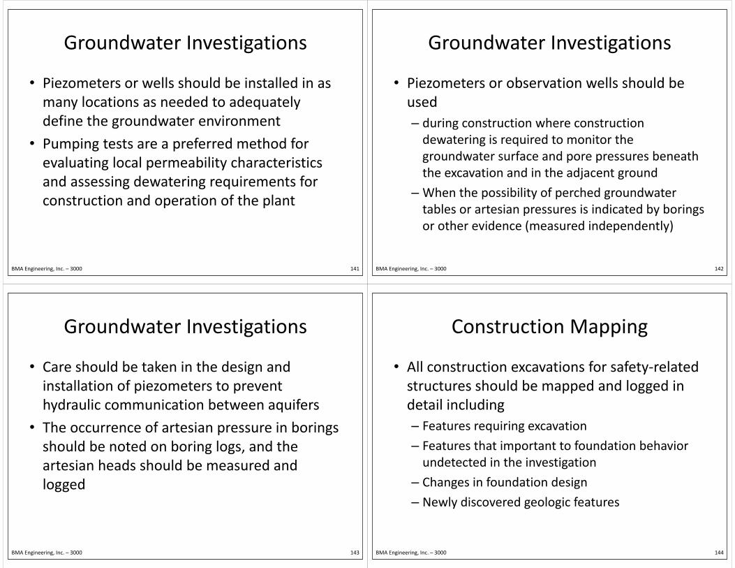
• Piezometers or wells should be installed in as many locations as needed to adequately y q ydefine the groundwater environment
• Pumping tests are a preferred method for• Pumping tests are a preferred method for evaluating local permeability characteristics
fand assessing dewatering requirements for construction and operation of the plant
BMA Engineering, Inc. – 3000 141
Groundwater InvestigationsGroundwater Investigations
• Piezometers or observation wells should be used – during construction where construction dewatering is required to monitor thedewatering is required to monitor the groundwater surface and pore pressures beneath the excavation and in the adjacent groundthe excavation and in the adjacent ground
– When the possibility of perched groundwater tables or artesian pressures is indicated by boringstables or artesian pressures is indicated by borings or other evidence (measured independently)
BMA Engineering, Inc. – 3000 142
Groundwater InvestigationsGroundwater Investigations
• Care should be taken in the design and installation of piezometers to prevent p phydraulic communication between aquifers
• The occurrence of artesian pressure in borings• The occurrence of artesian pressure in borings should be noted on boring logs, and the artesian heads should be measured and logged
BMA Engineering, Inc. – 3000 143
Construction MappingConstruction Mapping
• All construction excavations for safety‐related structures should be mapped and logged in pp ggdetail including– Features requiring excavation– Features requiring excavation
– Features that important to foundation behavior d t t d i th i ti tiundetected in the investigation
– Changes in foundation design
– Newly discovered geologic features
BMA Engineering, Inc. – 3000 144
Construction MappingConstruction Mapping
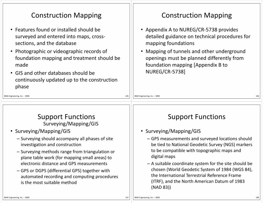
• Features found or installed should be surveyed and entered into maps, cross‐y p ,sections, and the database
• Photographic or videographic records of• Photographic or videographic records of foundation mapping and treatment should be made
• GIS and other databases should beGIS and other databases should be continuously updated up to the construction phasephase
BMA Engineering, Inc. – 3000 145
Construction MappingConstruction Mapping
• Appendix A to NUREG/CR‐5738 provides detailed guidance on technical procedures for g pmapping foundations
• Mapping of tunnels and other underground• Mapping of tunnels and other underground openings must be planned differently from ffoundation mapping [Appendix B to NUREG/CR‐5738]
BMA Engineering, Inc. – 3000 146
Support FunctionsSupport FunctionsSurveying/Mapping/GIS
• Surveying/Mapping/GIS– Surveying should accompany all phases of site y g p y pinvestigation and construction
– Surveying methods range from triangulation orSurveying methods range from triangulation or plane table work (for mapping small areas) to electronic distance and GPS measurementselectronic distance and GPS measurements
– GPS or DGPS (differential GPS) together with automated recording and computing proceduresautomated recording and computing procedures is the most suitable method
BMA Engineering, Inc. – 3000 147
Support FunctionsSupport Functions
• Surveying/Mapping/GIS– GPS measurements and surveyed locations should ybe tied to National Geodetic Survey (NGS) markers to be compatible with topographic maps and p p g p pdigital maps
– A suitable coordinate system for the site should beA suitable coordinate system for the site should be chosen (World Geodetic System of 1984 (WGS 84), the International Terrestrial Reference Framethe International Terrestrial Reference Frame (ITRF), and the North American Datum of 1983 (NAD 83))(NAD 83))
BMA Engineering, Inc. – 3000 148

Support FunctionsSupport Functions
• Database/Sample Repository/Quality Assurance– All data acquired during site investigation such as logs of operations, photographs, test results, andlogs of operations, photographs, test results, and engineering evaluations should be organized into suitable categories in accordance with qualitysuitable categories in accordance with quality assurance principles and procedures and entered into a GIS database to permit visual display ininto a GIS database to permit visual display in maps and cross sections
BMA Engineering, Inc. – 3000 149
Support FunctionsSupport Functions
• Database/Sample Repository/Quality Assurance– The site investigations should be included in the overall Quality Assurance program for plant designoverall Quality Assurance program for plant design and construction according to the guidance in Regulatory Guide 1.28 and the requirements ofRegulatory Guide 1.28 and the requirements of Appendix B to 10 CFR Part 50. Field operations and records preservation should, therefore, beand records preservation should, therefore, be conducted in accordance with quality assurance principles and proceduresprinciples and procedures
BMA Engineering, Inc. – 3000 150
3000 Site Investigation3000. Site Investigation
• Site Investigation for Foundations of N l P Pl t3100 Nuclear Power Plants
• Laboratory Investigations and Soil Sampling of Soils and Rocks for
3200Sampling of Soils and Rocks for Engineering Analysis and Design of Nuclear Power Plants
BMA Engineering, Inc. – 3000 151
3200. Laboratory Investigations of Soils and Rocks for Engineering Analysis and Design of
Nuclear Power PlantsNuclear Power Plants
• Laboratory Testing Program
• Soil Samples• Soil Samples
S l i d P i f T S i• Selection and Preparation of Test Specimens
• Testing Procedures For Determining Soil Properties
BMA Engineering, Inc. – 3000 152

3200. Laboratory Investigations of Soils and Rocks for Engineering Analysis and Design ofRocks for Engineering Analysis and Design of
Nuclear Power Plants • Laboratory Investigations of Soils and Rocks for Engineering Analysis and Design based on:g g y g– Regulatory Guide 1.138 that describes acceptable laboratory investigations and testing practices forlaboratory investigations and testing practices for determining soil and rock properties and characteristics needed for engineering analysischaracteristics needed for engineering analysis and design for foundations and earthworks for nuclear power plantsnuclear power plants
– NUREG/CR‐5739 (1999) that summarizes the processes required in a laboratory testing programprocesses required in a laboratory testing program
BMA Engineering, Inc. – 3000 153
3200. Laboratory Investigations of Soils and Rocks for Engineering Analysis and Design ofRocks for Engineering Analysis and Design of
Nuclear Power Plants • Purpose:
– To identify and classify soils and rocks and to y yevaluate their physical and engineering properties
BMA Engineering, Inc. – 3000 154
Laboratory Testing ProgramLaboratory Testing Program
• Laboratory facilities should have– Adequate test space, temperature controlled q p , pareas, and adequate ventilation and air flow
– Separate areas for dust‐ and vibration‐producingSeparate areas for dust and vibration producing activities such as sieve analyses, compaction tests, and sample processingand sample processing
– Separate room with about 100% relative humidity for storing samples if storage is neededfor storing samples if storage is needed
– Proper equipment to perform the tests
BMA Engineering, Inc. – 3000 155
Laboratory Testing ProgramLaboratory Testing Program
• Laboratory Equipment: – Test Apparatuspp
• Should conform to the standard specifications
• Description of essential characteristics if not standardDescription of essential characteristics if not standard
• Inspected and maintained regularly
– Calibration of Test Apparatus– Calibration of Test Apparatus• Pre‐service calibration of test apparatus
• Recalibration at intervals frequency according to the• Recalibration at intervals frequency according to the susceptibility to change and precision of measurement
BMA Engineering, Inc. – 3000 156

3200. Laboratory Investigations of Soils and Rocks for Engineering Analysis and Design of
Nuclear Power PlantsNuclear Power Plants
• Laboratory Testing Program
• Soil Samples• Soil Samples
S l i d P i f T S i• Selection and Preparation of Test Specimens
• Testing Procedures For Determining Soil Properties
BMA Engineering, Inc. – 3000 157
Soil SamplesSoil Samples
• Handling and Storage of Samples– Verifying the identification markings of all samples y g g pimmediately upon their arrival at the laboratory
– An inventory should be maintained of all samplesAn inventory should be maintained of all samples received
BMA Engineering, Inc. – 3000 158
Soil SamplesSoil Samples
• Handling and Storage of Disturbed Samples– Should be examined and tested after arrival in the laboratory
– Storage of the samples may be required forStorage of the samples may be required for several days or weeks for a large testing program
Samples to be used for fluid content– Samples to be used for fluid content determinations should be protected against change in water contentchange in water content
BMA Engineering, Inc. – 3000 159
Soil SamplesSoil Samples
• Handling and Storage of Undisturbed Samples– Should be protected from vibration, shock, p , ,significant temperature changes, and changes in water content
– Should be stored in humid rooms
Moisture seals should be checked periodically and– Moisture seals should be checked periodically and renewed as needed
Sh ld b i d f l i d– Should not be retained for long periods
BMA Engineering, Inc. – 3000 160

Soil SamplesSoil Samples
• Handling and Storage of Undisturbed Samples
– Duration of storage before
• Handling and Storage of Undisturbed Samples
Duration of storage before testing should be recorded for each sample testfor each sample test
– A sample compressor was found to be useful infound to be useful in prevent deterioration of clay samples during storageclay samples during storage (Brown and Chow (1988))
BMA Engineering, Inc. – 3000 161
Soil SamplesSoil Samples
• Handling and Storage of Rock Samples– Should be transported as fragile material and p gprotected from excessive changes in humidity and temperaturep
– Should be examined and tested as soon as possiblepossible
– May be stored for a large testing program and protected against damageprotected against damage
BMA Engineering, Inc. – 3000 162
Soil SamplesSoil Samples
• Initial Identification and Examination of Samplesp– ASTM D 2488: Practice for Description and Identification of SoilsIdentification of Soils
• Procedures for the description and identification of a soil sample based primarily on visual identification and soil sample based primarily on visual identification and manual test to aid in the evaluation of its significant properties for engineering
• Grouping similar soil samples so that only a minimum number of laboratory tests need be run
BMA Engineering, Inc. – 3000 163
Soil SamplesSoil Samples
• Initial Identification and Examination of Samplesp– ASTM D 4452: X‐Ray Radiography of Soil Samples
• Procedures for the detection of inherent abnormalitiesProcedures for the detection of inherent abnormalities and disturbances
• Enables the user to determine the effects of samplingEnables the user to determine the effects of sampling and natural variations within samples as identified by the extent of the relative penetration of X‐rays through soil samples
BMA Engineering, Inc. – 3000 164

Soil Samples• Initial Identification and Examination of Samples
– ASTM D 2487: Standard
Samples
Classification of Soils for Engineering Purposes (Unified Soil Classification System)
• soil groups and method of identification in a
if l ifi iuniform classification procedure
BMA Engineering, Inc. – 3000 165
Soil SamplesSoil Samples
• Initial Identification and Examination of Samplesp– RTH 102‐93: Rock Testing Handbook, 1993
• Procedures used in the petrographic examination ofProcedures used in the petrographic examination of rock core samples
• Determines the physical and chemical properties of aDetermines the physical and chemical properties of a material
• Describes and classifies a samplep
• Determines the amount of specific materials that may affect the specimen’s intended use
BMA Engineering, Inc. – 3000 166
3200. Laboratory Investigations of Soils and Rocks for Engineering Analysis and Design of
Nuclear Power PlantsNuclear Power Plants
• Laboratory Testing Program
• Soil Samples• Soil Samples
S l i d P i f T S i• Selection and Preparation of Test Specimens
• Testing Procedures For Determining Soil Properties
BMA Engineering, Inc. – 3000 167
Selection and Preparation of Test Specimens
• Selection of soil and rock specimens for laboratory testing requires careful y g qexamination of boring records and available samplessamples
• Test specimens should be accurately described fand representative of the soil or rock unit to
permit establishment of the soil profile
• Average and variability range of test values for material properties should be identifiedmaterial properties should be identified
BMA Engineering, Inc. – 3000 168

Selection and Preparation of Test Specimens
• Testing should be of the most representative samples, those with extreme properties and p , p pthose representative of critical zones
• High quality undisturbed samples are• High‐quality undisturbed samples are preferred for all tests of strength and dynamic
fresponses of in situ soils
• Undisturbed test samples should be preparedUndisturbed test samples should be prepared in a humid room to preserve the natural structure and water content of the materialstructure and water content of the material
BMA Engineering, Inc. – 3000 169
Selection and Preparation of Test Specimens
• Undisturbed Samples
• Reconstituted or Remolded SamplesReconstituted or Remolded Samples
• Scalping of Large Particles
• Laboratory Testing Program
BMA Engineering, Inc. – 3000 170
Selection and Preparation of Test Specimens
• Test Specimens of Undisturbed Samples– Undisturbed tube samples of soils should be pexamined for evidence of disturbance
– To minimize damage during the removal of aTo minimize damage during the removal of a sample from the sample tube, split the tube longitudinally by milling or saw the tubelongitudinally by milling, or saw the tube transversely into segments of sufficient length to extrude a single test specimen from each and trimextrude a single test specimen from each and trim off the ends
BMA Engineering, Inc. – 3000 171
Selection and Preparation of Test Specimens
• Undisturbed tube samples should satisfy the following criteria:g(1) The specific recovery ratio should be between 90 and 100 percentand 100 percent
(2) No visible distortions, planes of failure, pitting, discoloration or other signs of disturbance on thediscoloration, or other signs of disturbance on the surface of or in sliced sections of the sample
(3) N h i th l t l th d i ht(3) No change in the sample net length and weight and results of other control tests during shipment, t d h dlistorage, and handling
BMA Engineering, Inc. – 3000 172

Selection and Preparation of Test Specimens
• Test Specimens of Undisturbed Samples– Samples that have been subjected to violent p jmechanical shocks or to accidental freezing and thawing should not be considered to be gundisturbed
– Test specimens should be representative of eachTest specimens should be representative of each discrete soil or rock unit to be tested and should be accurately described on the basis ofbe accurately described on the basis of classification tests to permit establishment of the soil and geologic profilessoil and geologic profiles
BMA Engineering, Inc. – 3000 173
Selection and Preparation of Test Specimens
• Test Specimens of Undisturbed Samples– The best quality and most representative q y pundisturbed samples available should be used in physical and engineering property tests of in situ p y g g p p ysoils
– Trimming and shaping of test specimens of soilsTrimming and shaping of test specimens of soils require great care to prevent disturbance and changes in water contentchanges in water content
– Frozen samples should be prepared under conditions that will prevent premature thawingconditions that will prevent premature thawing
BMA Engineering, Inc. – 3000 174
Selection and Preparation of Test Specimens
• Test Specimens of Undisturbed Samples– EM 1110‐2‐1906: Laboratory Soils Testing y g
• Describes procedures for preparing soil samples for testing for making determinations of the soil properties
– ASTM D 4452: X‐Ray Radiography of Soil Samples• Can be used to determine the quality of a sampleCan be used to determine the quality of a sample before testing
– High‐quality undisturbed samples are preferredHigh quality undisturbed samples are preferred for all tests of strength and dynamic responses of in situ soils whether cohesive or cohesionlessin situ soils, whether cohesive or cohesionless
BMA Engineering, Inc. – 3000 175
Selection and Preparation of Test Specimens
• Test Specimens of Reconstituted or Remolded Samplesp– Used when representative undisturbed samples cannot be obtainedcannot be obtained
– Remolded samples are used as representative of compacted fill or backfill material for newcompacted fill or backfill material for new construction
U di t b d l f th fill t k f– Undisturbed samples of earth fill are taken for confirmatory testing during construction
BMA Engineering, Inc. – 3000 176

Selection and Preparation of Test Specimens
• Test Specimens of Reconstituted or Remolded Samplesp– Undisturbed samples are also taken in the testing and reevaluation of existing structuresg
– Reconstituted specimens representative of in situ material should be molded to the in situ density and ymoisture content as determined from actual field measurements
– Fill material samples should be molded to the range of densities and water contents under field conditions
BMA Engineering, Inc. – 3000 177
Selection and Preparation of Test Specimens
• Test Specimens of Reconstituted or Remolded Samplesp– Laboratory personnel should record a complete detailed description of the specimendetailed description of the specimen
• identification of the material, color, consistency, brittleness of the material, and indication of brittleness of the material, and indication of disturbance of boring samples
– Disturbed samples should not be used for any testDisturbed samples should not be used for any test other than classification, specific gravity, or water contentcontent
BMA Engineering, Inc. – 3000 178
Selection and Preparation of Test Specimens
• Scalping of Large Particles– Gravel and large particles are typically scalped, or g p yp y p ,removed from the total sample, and the finer fraction tested
– Laboratory investigations depend on the design requirements and nature of problemsrequirements and nature of problems encountered or suspected at the site
BMA Engineering, Inc. – 3000 179
Selection and Preparation of Test Specimens
• Laboratory Testing Program– Study of soil and rock mechanics includes yinvestigation, description, classification, testing, and analysis of soil and rock to determine their yinteraction with structures built in or upon them, or built with them
– Carrying out tests on samples of soil in a laboratory to determine physical properties oflaboratory to determine physical properties of soils and rocks
BMA Engineering, Inc. – 3000 180

Selection and Preparation of Test Specimens
• Laboratory Testing Program– Physical properties of soils and rocks should be y p pdetermined by carrying out two main categories of tests on samples of soil in a laboratoryp y
• Classification tests indicate general type of soil and engineering category to which it belongs
• Engineering properties tests require careful considerations of field conditions, various design loading conditions, material properties, and possible problems at the site.
BMA Engineering, Inc. – 3000 181
Selection and Preparation of Test Specimens
• Laboratory Testing Program– Investigation and evaluation of sites for nuclear gpower plants require the evaluation of
• Site response to earthquake loading and otherSite response to earthquake loading and other dynamic loading conditions and analysis of earthquake loading effects on the stability of slope and embankments
• Wave propagation characteristics of subsurface i l i h i i ff fmaterials with interaction effects of structures
• Analysis of the potential for soil liquefaction, settlement under dynamic loading andsettlement under dynamic loading, and
BMA Engineering, Inc. – 3000 182
Selection and Preparation of Test Specimens
• Laboratory Testing Program– Basic parameters required as input for dynamic p q p yresponse analyses of soils include
• Total mass density, relative density, Poisson’s ratio,Total mass density, relative density, Poisson s ratio, static soil strength, initial stress conditions, shear and compressional wave velocities, and the dynamic shear modulus and damping ratio
• Variation of strength, moduli, and damping with strain
BMA Engineering, Inc. – 3000 183
3200. Laboratory Investigations of Soils and Rocks for Engineering Analysis and Design of
Nuclear Power PlantsNuclear Power Plants
• Laboratory Testing Program
• Soil Samples• Soil Samples
S l i d P i f T S i• Selection and Preparation of Test Specimens
• Testing Procedures For Determining Soil Properties
BMA Engineering, Inc. – 3000 184

Testing Procedures For Determining Soil Properties
Testing Procedures For Determining Static Soil PropertiesSoil Properties
Testing Procedures For Determining Dynamic Soil Propertiesy p
Testing Procedures For DeterminingTesting Procedures For Determining Engineering Properties of Rock
BMA Engineering, Inc. – 3000 185
Testing Procedures For Determining Static Soil Properties
• Laboratory tests on soil and rock material should be thorough and of documented gquality to permit a realistic estimate of properties and subsurface conditionsproperties and subsurface conditions
• Laboratory Personnel should be responsible ffor handling samples, preparing test specimens, specifying testing procedures and operations, with all related Documentation
BMA Engineering, Inc. – 3000 186
Testing Procedures For Determining Static Soil Properties
• Soil Testing– Classification tests and determination of engineering properties should be performed according to an accepted and published method. g p p
– Laboratory procedures for some of the most common tests along with other relatedcommon tests, along with other related references, are shown in Appendix A to RG 1.138
BMA Engineering, Inc. – 3000 187
Testing Procedures For Determining Static Soil Properties
• Soil Testing: Most common soil tests include
Water Content PermeabilityWater Content PermeabilityUnit Weights ConsolidationVoid Ratio Direct Shear TestPorosity Triaxial Compression TestsSaturation Unconfined Compression TestsAtterberg Limits Relative DensitySpecific Gravity Grain Size AnalysisErodibility Tests CompactionErodibility Tests Compaction
BMA Engineering, Inc. – 3000 188
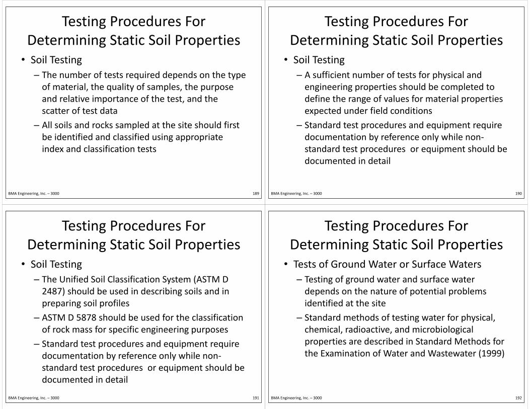
Testing Procedures For Determining Static Soil Properties
• Soil Testing– The number of tests required depends on the type q p ypof material, the quality of samples, the purpose and relative importance of the test, and the p ,scatter of test data
– All soils and rocks sampled at the site should firstAll soils and rocks sampled at the site should first be identified and classified using appropriate index and classification testsindex and classification tests
BMA Engineering, Inc. – 3000 189
Testing Procedures For Determining Static Soil Properties
• Soil Testing– A sufficient number of tests for physical and p yengineering properties should be completed to define the range of values for material properties g p pexpected under field conditions
– Standard test procedures and equipment requireStandard test procedures and equipment require documentation by reference only while non‐standard test procedures or equipment should bestandard test procedures or equipment should be documented in detail
BMA Engineering, Inc. – 3000 190
Testing Procedures For Determining Static Soil Properties
• Soil Testing– The Unified Soil Classification System (ASTM D y (2487) should be used in describing soils and in preparing soil profiles p p g p
– ASTM D 5878 should be used for the classification of rock mass for specific engineering purposesof rock mass for specific engineering purposes
– Standard test procedures and equipment require documentation by reference only while nondocumentation by reference only while non‐standard test procedures or equipment should be documented in detaildocumented in detail
BMA Engineering, Inc. – 3000 191
Testing Procedures For Determining Static Soil Properties
• Tests of Ground Water or Surface Waters– Testing of ground water and surface water g gdepends on the nature of potential problems identified at the site
– Standard methods of testing water for physical, chemical radioactive and microbiologicalchemical, radioactive, and microbiological properties are described in Standard Methods for the Examination of Water and Wastewater (1999)the Examination of Water and Wastewater (1999)
BMA Engineering, Inc. – 3000 192

Testing Procedures For Determining Static Soil Properties
• Tests of Ground Water or Surface Waters– The standard methods include methods of testing gpolluted water, wastewaters, effluents, bottom sediments, and sludges, g
– Standard testing methods should be used unless special problems are encountered that requirespecial problems are encountered that require modifications or alternative methods
BMA Engineering, Inc. – 3000 193
Testing Procedures For Determining Dynamic Soil Properties
• Before dynamic tests are performed, the initial state of stress in the soil should be determined, and a series of static consolidated‐drained and consolidated‐consolidated drained and consolidatedundrained triaxial compression tests should be made to determine static strengthmade to determine static strength
BMA Engineering, Inc. – 3000 194
Testing Procedures For Determining Dynamic Soil Properties
• Dynamic testing program should include tests to determine – Soil parameters needed as input for reference analyses and soil structure interaction studiesanalyses and soil structure interaction studies
– Dynamic strength characteristics and liquefaction potential of soilspotential of soils
• Dynamic soils property testing includes Cyclic Triaxial Tests and Resonant Column Tests
BMA Engineering, Inc. – 3000 195
Testing Procedures For Determining Dynamic Soil Properties
• Cyclic Triaxial Tests– Cyclic loading technique for investigating y g q g gliquefaction resistance factors
– Most common due to availability of equipmentMost common due to availability of equipment and ease of preparing undisturbed specimens
Lnability of the test to accurately represent field– Lnability of the test to accurately represent field earthquake stresses and boundary conditions
BMA Engineering, Inc. – 3000 196
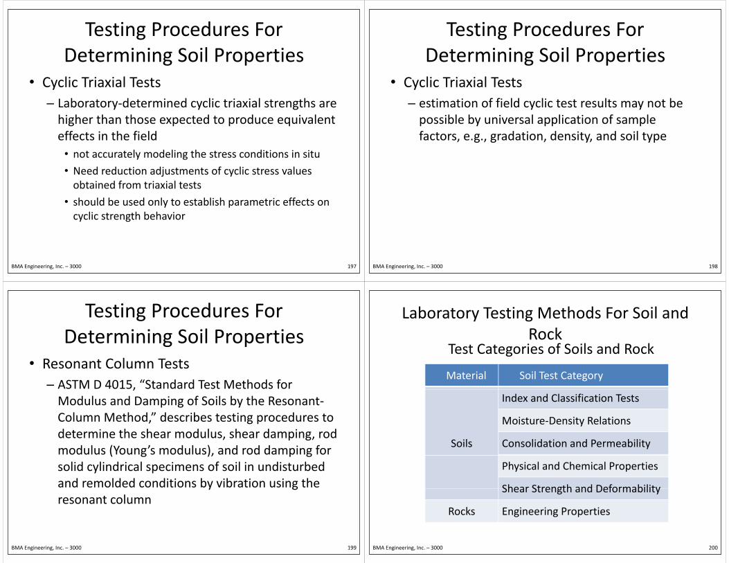
Testing Procedures For Determining Soil Properties
• Cyclic Triaxial Tests– Laboratory‐determined cyclic triaxial strengths are y y ghigher than those expected to produce equivalent effects in the field
• not accurately modeling the stress conditions in situ
• Need reduction adjustments of cyclic stress valuesNeed reduction adjustments of cyclic stress values obtained from triaxial tests
• should be used only to establish parametric effects on y pcyclic strength behavior
BMA Engineering, Inc. – 3000 197
Testing Procedures For Determining Soil Properties
• Cyclic Triaxial Tests– estimation of field cyclic test results may not be y ypossible by universal application of sample factors, e.g., gradation, density, and soil type, g , g , y, yp
BMA Engineering, Inc. – 3000 198
Testing Procedures For Determining Soil Properties
• Resonant Column Tests– ASTM D 4015, “Standard Test Methods for ,Modulus and Damping of Soils by the Resonant‐Column Method,” describes testing procedures to , g pdetermine the shear modulus, shear damping, rod modulus (Young’s modulus), and rod damping for ( g ), p gsolid cylindrical specimens of soil in undisturbed and remolded conditions by vibration using the y gresonant column
BMA Engineering, Inc. – 3000 199
Laboratory Testing Methods For Soil and Rock
Test Categories of Soils and Rock
Material Soil Test Category
g
Index and Classification Tests
Moisture‐Density Relations
Soils
Moisture Density Relations
Consolidation and Permeability
Physical and Chemical Properties
Shear Strength and DeformabilityShear Strength and Deformability
Rocks Engineering Properties
BMA Engineering, Inc. – 3000 200

Laboratory Testing Methods For Soil
S il f i i dSoil Test Category
Name of Test Properties or Parameters Determined
Gradation Particle size distributionAnalysis
Percent fines Percent of weight of material finer than No. 200 sieve
Index and Classification
AtterbergLimits
Liquid and plastic limit, plasticity index,shrinkage factor (limit)
S ifi S ifi i ifi iof Soils Specific Gravity
Specific gravity, apparent specific gravity,bulk unit weight sufficiently fine toeliminate internal voids in the intact rock
Radiography Qualitative test of sample quality
Description of Soil and Rock
Description of soil from visual‐manualexamination
BMA Engineering, Inc. – 3000 201
Laboratory Testing Methods For Soil
Soil Test Category
Name of Test Properties or Parameters Determined
Moisture‐
Bulk Unit Weight Bulk unit weight (bulk density)
Water (M i )
Water content as a percent of dry weightMoisture‐Density Relationsof Soil
(Moisture)Content
Relative Density Maximum and minimum density of of Soilcohesionless soils
Compaction Maximum dry unit weight of soil
Consolidatio Consolidation One dimensional compressibilityConsolidation and Permeability of Soil
Consolidation One‐dimensional compressibility, permeability of cohesive Soil
Permeability Permeabilityof Soil
BMA Engineering, Inc. – 3000 202
Laboratory Testing Methods For Soil
Soil Test Category
Name of Test Properties or Parameters Determined
Mineralogy Identification of minerals
Organic Content Organic and inorganic carbon content f d i h
Physical and Chemical Properties
as percent of dry weight
Soluble Salts Concentration of soluble salts in soil pore waterProperties
of Soil Erodibility Tests(Pinhole Test, Crumb Test, SCS Test,
Significant in evaluationof potential erosion or piping.
, ,Cylinder Dispersion)
BMA Engineering, Inc. – 3000 203
Laboratory Testing Methods For Soil
S il f i i dSoil Test Category
Name of Test Properties or Parameters Determined
Unconfined Strength of cohesive soil in uniaxialCompression compression
Direct Shear,Consolidated‐
Cohesion and angle of internal friction under drained conditions
Shear Strength and D f bili
drained
TriaxialCompression
Shear strength parameters; Cohesion and angle of internal friction for soilsDeformability
of Soil
Compression ,Unconsolidated‐Undrained
and angle of internal friction for soilsof low permeability
Triaxial Shear strength parameters; CohesionTriaxialCompression,Consolidated‐Drained
Shear strength parameters; Cohesionand angle of internal friction. For long‐term loading conditions
Drained
BMA Engineering, Inc. – 3000 204

Laboratory Testing Methods For Soil
S il f i i dSoil Test Category
Name of Test Properties or Parameters Determined
Triaxial Shear strength parameters; CohesionCompression,Consolidated‐Undrained
and angle of internal friction for consolidated soil. With pressuremeasurements, cohesion and friction
Shear Strength and Deformability (C ) f S il
may be obtained
Cyclic Triaxial Local strain, modulus and damping
Cyclic Simple Shear Shear modulus and damping values(Cont.) of Soil Cyclic Simple Shear Shear modulus and damping values and cyclic‐strength of cohesive andcohesionless soils
Resonant Column Shear modulus and damping inResonant Column Shear modulus and damping in cohesive and cohesionless soils
BMA Engineering, Inc. – 3000 205
Testing Procedures For Determining Engineering Properties of Rock
• Common tests include
Porosity Unconfined CompressionPorosity Unconfined CompressionPermeability Triaxial CompressionSeismic Velocity Slate DurabilitySeismic Velocity Slate DurabilityDirect Tensile Strength
Specific GravityDirect Shear
p yDirect Shear
BMA Engineering, Inc. – 3000 206
Laboratory Testing Methods For Rocks
k f i i dRock Test Category
Name of Test Properties or Parameters Determined
Water Content Water Content
Specific Gravity
Porosity Bulk unit weight, specific gravity, and total porosity (Melcher Method) or effective
Engineering P i
porosity (Melcher Method) or effective porosity (Simmons orWashburn‐Bunting Method)
bili bili f i kProperties of Rocks
Permeability Permeability of intact rock
Degradation Resistance
Percent of weight of rock greater than 3/4 in (19 mm)
Seismic Velocity Compressional and shear wave velocities in intact rock
Direct Tensile Uniaxial tensile strength of intact rockDirect Tensile Strength
Uniaxial tensile strength of intact rock
BMA Engineering, Inc. – 3000 207
Laboratory Testing Methods For Rocks
k f iRock Test Category
Name of Test Properties or Parameters Determined
Splitting Tensile Strength Indirect measure of tensile strength (“Brazilian Test”) of intact rock
Modulus of Rupture Indirect measure of tensile strength of intact rock
Engineering Properties of Rocks
UnconfinedCompression
Young’s moduli and unconfined compression strength of intact rock
U i i l C i Y ’ d li P i iof Rocks (Cont..)
Uniaxial Compression Young’s moduli, Possion ratio
Triaxial CompressionUndrained
Young’s moduli, cohesion frictionparameters of failure Envelope
Triaxial CompressionWithout Pore Pressure Measurements
Young’s moduli, cohesion frictionParameters
BMA Engineering, Inc. – 3000 208

Laboratory Testing Methods For Rocks
k f iRock Test Category
Name of Test Properties or Parameters Determined
Triaxial Compression Young’s moduli, cohesion frictionEngineering Properties of Rocks (C t )
With Pore Pressure Measurements
parameters of effective stress conditions
Slake Durability Index of resistance to Slaking(Cont..)
y g
Direct Shear Shear strength
BMA Engineering, Inc. – 3000 209
Completed Items of Overall OutlineCompleted Items of Overall Outline
1000. Introduction
2000. Federal Regulations, Guides, and Reports
3000. Site Investigation
4000. Loads, Load Factors, and Load Combinations
5000. Concrete Structures and Construction
6000. Steel Structures and Construction
7000. General Construction Methods
8000. Exams and Course Evaluation
9000. References and Sources
210BMA Engineering, Inc. – 3000
3000 Site Investigation3000. Site Investigation
• Objective and Scope Met– Present and discuss
• Site investigation for foundations of nuclear power plants
• Laboratory investigations and soil sampling of soils and rocks for engineering analysis and design of nuclear power plants
BMA Engineering, Inc. – 3000 211