04 udf scalar
TRANSCRIPT

Tutorial: UDFs for a User-Defined Scalar
Introduction
ANSYS FLUENT solves the the transport equation for a user-defined scalar (UDS) in thesame way as it solves the transport equation for a scalar in the core equations, such asa species mass fraction. The UDS capability can be used to implement a wide range ofphysical models in magnetohydrodynamics, electromagnetics, and more.
In this tutorial you will learn to solve a general scalar diffusion equation (1) with thepossible types of boundary condition (BC) at the boundary (or a part of the boundary) ofthe domain.
c∂φ
∂t−∇. (Γ∇φ) = Sφ, in Ω, t > 0 (1)
The possible types of boundary conditions are as follows:
• Dirichlet BC: φ = D0
• Neumann BC: −Γ(∂φ/∂n) = q0
• Mixed BC: −Γ(∂φ/∂n) = hc(φ− φ∞)
Here, D0, q0, hc, and φ∞ are constant values.
Prerequisites
This tutorial is written with the assumption that you have completed Tutorial 1 fromANSYS FLUENT 12.0 Tutorial Guide, and that you are familiar with the ANSYS FLUENTnavigation pane and menu structure. Some steps in the setup and solution procedure willnot be shown explicitly.
For more details about UDFs, see ANSYS FLUENT 12.0 UDF Manual.
Problem Description
As shown in the problem illustration, the problem is a 2D rectangle, with constant flux,constant value, and mixed boundary conditions along the boundary edges.
c© ANSYS, Inc. October 1, 2009 1

Tutorial: UDFs for a User-Defined Scalar
For the problem,
Γ = 0.162 W/(m K)Cp = Specific heat of the material [1650 J/(kg K)]φ∞ = 550oChC = 20 W/(m2K)
Figure 1: Schematic
Setup and Solution: Steady-State Solver
Preparation
1. Copy the files (laplace.msh, mixedbc.c, and transientMixedBC.c) to your workingfolder.
2. Use FLUENT Launcher to start the 2D version of ANSYS FLUENT.
For more information about FLUENT Launcher see Section 1.1.2, StartingANSYS FLUENT Using FLUENT Launcher in ANSYS FLUENT 12.0 User’s Guide.
3. Enable Double-Precision in the Options list.
4. Click the UDF Compiler tab and ensure that the Setup Compilation Environment forUDF is enabled.
The path to the .bat file which is required to compile the UDF will be displayed assoon as you enable Setup Compilation Environment for UDF.
If the UDF Compiler tab does not appear in the FLUENT Launcher dialog box by default,click the Show More >> button to view the additional settings.
2 c© ANSYS, Inc. October 1, 2009

Tutorial: UDFs for a User-Defined Scalar
The Display Options are enabled by default. Therefore, after you read in the mesh, itwill be displayed in the embedded graphics window.
Step 1: Mesh
1. Read the mesh file (laplace.msh).
File −→ Read −→Mesh...
As the mesh file is read, ANSYS FLUENT will report the progress in the console.
Step 2: General Settings
1. Retain the default solver settings.
General
2. Check the mesh.
General −→ Check
ANSYS FLUENT will perform various checks on the mesh and will report the progressin the console. Make sure the minimum volume reported is a positive number.
Step 3: User-Defined Functions
1. Set the UDS value.
Define −→ User-Defined −→Scalars...
(a) Set Number of User-Defined Scalars to 1.
(b) Select none from Flux Function drop-down list.
(c) Click OK to close User-Defined Scalars dialog box.
2. Compile the UDF (mixedbc.c).
Define −→ User-Defined −→ Functions −→Compiled...
c© ANSYS, Inc. October 1, 2009 3

Tutorial: UDFs for a User-Defined Scalar
(a) Click Add... and select the source file, mixedbc.c.
(b) Click Build to build the library.
A Warning dialog box opens, asking you to ensure that the UDF source files arein the same folder that contains the case and data files. Click OK.
(c) Click Load to load the newly created UDF library.
Step 4: Materials
1. Create a new material (mapel).
Materials −→ air −→ Create/Edit...
(a) Retain the default values for Density and Viscosity.
(b) Click Edit... for UDS Diffusivity and enter 0.162 for the Coefficient.
(c) Enter maple for the Name.
(d) Click Change/Create.
A Question dialog box appears, asking you whether to overwrite air. Click Yes.
(e) Close the Create/Edit Materials dialog box.
4 c© ANSYS, Inc. October 1, 2009

Tutorial: UDFs for a User-Defined Scalar
Step 5: Boundary Conditions
1. Set the boundary conditions for topwall.
Boundary Conditions −→ topwall −→ Edit...
(a) Click UDS tab.
(b) Select Specified Value from the User Scalar 0 drop-down list in the User-DefinedScalar Boundary Condition group box.
(c) Enter 80 for UDS Scalar 0 in the User-Defined Scalar Boundary Value group box.
(d) Click OK.
2. Set the boundary conditions for leftwall.
Boundary Conditions −→ leftwall −→ Edit...
(a) Click UDS tab.
(b) Ensure that Specified Flux is selected from the User Scalar 0 drop-down list.
(c) Retain 0 for UDS Scalar 0.
(d) Click OK.
3. Set the boundary conditions for rightwall.
Boundary Conditions −→ rightwall −→ Edit...
(a) Click UDS tab and select Specified Value from the User Scalar 0 drop-down listin the User-Defined Scalar Boundary Condition group box.
(b) Select udf scalarMixedBC::libudf from the User Scalar 0 drop-down list in the User-Defined Scalar Boundary Value group box.
c© ANSYS, Inc. October 1, 2009 5

Tutorial: UDFs for a User-Defined Scalar
(c) Click OK.
4. Set the similar boundary conditions for bottomwall. Repeat step 3 (previous step).
The following equation gives mixed boundary condition for rightwall and bottomwall.
−(
Γ∂φ
∂n
)w
= hC(φ− φ∞) (2)
where,Γ = UDS diffusivity [0.162]hC = 20φ∞ = 550
Step 6: Solution for Steady-State Solver
1. Deselect the Flow equation.
Solution Controls −→ Equations...
2. Disable Check Convergence for uds-0.
Monitors −→ Residuals −→ Edit...
3. Define a point monitor.
Surface −→Point...
(a) Enter 0.025 for x0 (m) and 0.05 for y0 (m).
(b) Enter middlepoint for the Name.
(c) Click Create and close Point Surface dialog box.
4. Enable the plotting of the point monitor.
Monitors (Surface Monitors)−→ Create...
(a) Enable Plot and Write.
(b) Retain the selection of Iteration from the X Axis and Every drop-down lists.
(c) Select Sum from the Report Type drop-down list.
(d) Select User Defined Scalars... and Scalar-0 from the Field Variable drop-down lists.
(e) Select middlepoint from the Surfaces list.
(f) Click OK to close the Surface Monitor dialog box.
5. Initialize the solution.
Solution Initialization
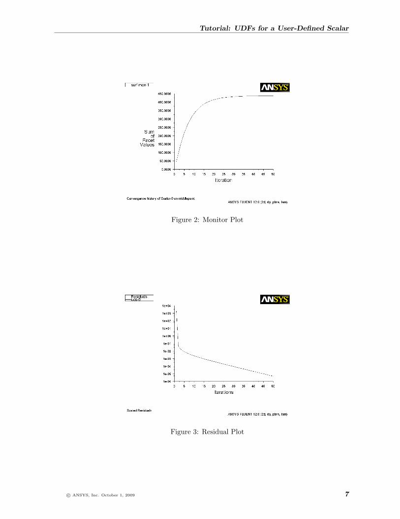
6. Run the calculation for 50 iterations (see Figures 2 and 3).
As the value of φ remains constant after 40 iterations (Figure 2), you can considerthat the solution as converged.
7. Save the case and data files (laplace.cas/dat.gz).
6 c© ANSYS, Inc. October 1, 2009
Tutorial: UDFs for a User-Defined Scalar
Figure 2: Monitor Plot
Figure 3: Residual Plot
c© ANSYS, Inc. October 1, 2009 7

Tutorial: UDFs for a User-Defined Scalar
Step 7: Postprocessing
Display the contours of φ.
1. Select User Defined Scalars... and Scalar-0 from the Contours of drop-down lists.
2. Click Display (see Figure 4).
Figure 4: Contours of φ
Since the problem is partially set up in the steady case, here only the unique steps for thesetup of the unsteady solver are mentioned.
Setup and Solution: Unsteady UDS Solver
The unsteady diffusion problem represented by equation 9 over the same rectangular domainis solved by a first-order implicit formulation. The boundary condition is also unchanged.The initial condition is φ = 80 through the domain.
Step 1: General Settings
1. Read the case file laplace.cas.gz.
2. Enable the transient solver.
General −→ Transient
Step 2: User-Defined Functions
1. Compile the UDF (transientMixedBC.c).
Define −→ User-Defined −→ Functions −→Compiled...
8 c© ANSYS, Inc. October 1, 2009

Tutorial: UDFs for a User-Defined Scalar
(a) Click Add... and select the source file, transientMixedBC.c.
(b) Enter libudf1 for the Library Name.
(c) Click Build to build the library.
A Warning dialog box opens, asking you to ensure that the UDF source files arein the same folder that contains the case and data files. Click OK.
(d) Click Load to load the newly created UDF library.
2. Select first-order unsteady UDF.
Define −→ User-Defined −→Scalars...
(a) Retain Number of User-Defined Scalars to 1.
(b) Retain the selection of none from Flux Function drop-down list.
(c) Select unst1storder::libudf1 from Unsteady Function drop-down list.
(d) Click OK to close User-Defined Scalars dialog box.
Step 3: Solution for Unsteady Solver
1. Initialize the solution by setting User Scalar 0 to 80.
Solution Initialization
2. Autosave the data files every 10 steps.
Calculation Activities
(a) Enter 10 for Autosave Every (Time Steps).
(b) Click Edit... to open Autosave dialog box.
i. Retain the default settings.
ii. Click OK to close the Autosave dialog box.
c© ANSYS, Inc. October 1, 2009 9

Tutorial: UDFs for a User-Defined Scalar
3. Set the time-stepping parameters.
Run Calculation
(a) Enter 0.1 s for Time Step Size.
(b) Enter 200 for Number of Time Steps.
(c) Enter 40 for Max Iterations/Time Step.
(d) Click Calculate.
Step 3: Postprocessing
1. Display the contours of φ at t = 1 s.
For displaying the contours t = 1 s, you need to read the data file (laplace-1-00010.dat).
(a) Select User Defined Scalars... and Scalar-0 from the Contours of drop-down lists.
(b) Click Display (see Figure 5).
Figure 5: Contours of φ at t = 1 s
2. Similarly, display contours of φ at t = 2 s, t = 3 s, and t = 4 s reading appropriatedata files (Figures 6–8).
The diffusion of φ into the domain due to high φ∞ in the ambient is clearly visiblevia the mixed (convective) boundary condition.
10 c© ANSYS, Inc. October 1, 2009

Tutorial: UDFs for a User-Defined Scalar
Figure 6: Contours of φ at t = 2 s
Figure 7: Contours of φ at t = 3 s
c© ANSYS, Inc. October 1, 2009 11

Tutorial: UDFs for a User-Defined Scalar
Figure 8: Contours of φ at t = 4 s
12 c© ANSYS, Inc. October 1, 2009

Tutorial: UDFs for a User-Defined Scalar
Appendix A: Steady-State Solver
Consider a steady-state scalar equation with constant Γ and zero source term (Sφ = 0) asfollows:
−∇ . (Γ∇φ) = 0 (3)
This is the Laplace’s equation. Solving the Laplaces’s equation using the ANSYS FLUENTUDS solver does not necessarily require user-defined functions (UDFs). You can activatethe UDS from the graphical user interface. ANSYS FLUENT UDS provides only Dirichletand Neumann conditions for the boundaries. Hence, you need to use the UDF to apply themixed boundary condition for the UDS equation.
Formulation of the Mixed Boundary Condition
Figure 9: Mixed Boundary Condition
For a generic cell c0 adjacent to the boundary, the diffusive flux across the boundary facef of the cell is expressed as follows:
−∫f
Γ(∂φ
∂n
)dS =
∫fhC(φ− φ∞)dS (4)
Using the mid-point rule of surface integral, the diffusive flux can be approximated as:
− Γf(∂φ
∂n
)fAf = hC(φf − φ∞)Af (5)
c© ANSYS, Inc. October 1, 2009 13

Tutorial: UDFs for a User-Defined Scalar
In ANSYS FLUENT, the diffusive flux is approximated in two parts:
1. The primary gradient is evaluated implicitly along the line connecting the cell centroidc0 to the centroid face f .
2. It is corrected by a secondary gradient (or cross diffusion) term evaluated explicitlyby the gradient obtained from the previous iteration (∇φ).
Γf(∂φ
∂n
)fAf ≈ Γf
(φf − φc0)dr
(−→A .−→A
−→A . −→es
)︸ ︷︷ ︸
primary
+ Γf
(∇φ . −→A − ∇φ . −→es
−→A .−→A
−→A . −→es
)︸ ︷︷ ︸
secondary
(6)
ANSYS FLUENT provides you with two macros:
• BOUNDARY FACE GEOMETRY(f, t, A, ds, es, A by es, dr0): a macro which definesthe necessary geometrical variables of the cell.
• BOUNDARY SECONDARY GRADIENT SOURCE(source,SV UDSI G(i),dG,es,A by es,k): amacro which calculates the secondary gradient term in equation 6.
If you designate the secondary gradient term in equation 6 as β0, and (−→A .−→A )/(−→A . −→es) as
Abe, equations 5 and 6 can be written as:
− hC(φf − φ∞)Af = Γf(φf − φc0)
drAbe + β0 (7)
φf can be expressed as follows:
φf =Γf (Abe/dr)φc0 − β0 + hCAfφ∞
hCAf + Γf (Abe/dr)(8)
The mixed boundary condition for the UDS is ready to be specified by boundary profile φfin equation 8 through the UDF macro DEFINED PROFILE().
14 c© ANSYS, Inc. October 1, 2009

Tutorial: UDFs for a User-Defined Scalar
UDF Code
The UDF code for steady state is as follows:
/***************************************************************************************/
/* Implementation of the mixed boundary condition for a UDS (or multiple): */
/* q = hC ( phi - PHI_inf) */
/***************************************************************************************/
#include "udf.h"
#include "sg.h" /* needed for the boundary and secondary gradient macros */
/*=====================================================================================*/
#define CP 1650.0 /* heat capacity for maple in (J/kg K) */
#define HTC 20.0 /* heat transfer coefficient for the problem */
#define TINF 550 /* ambient temperature of the problem */
/*=====================================================================================*/
/* Names of the user-defined scalar to be used */
enum
phi1,
N_REQUIRED_UDS
;
DEFINE_PROFILE(scalarMixedBC, thread, nv)
/*constants must be specified correctly for the mixed BC */
real hC, PHI1_inf;
/* ====================== */
face_t f;
real A[ND_ND], dG[ND_ND], dr0[ND_ND], es[ND_ND], dr, A_by_es;
real Af;
real beta0, gamma;
real temp1, temp2;
Thread *t0=thread->t0;
hC=HTC;
PHI1_inf=TINF;
begin_f_loop(f, thread)
/* identify the cell thread adjecent to the face thread f */
cell_t c0 = F_C0(f, thread);
BOUNDARY_FACE_GEOMETRY(f, thread, A, dr, es, A_by_es, dr0);
Af=NV_MAG(A);
gamma=C_UDST_DIFF(c0, t0, phi1);
if (NULLP(T_STORAGE_R_NV(t0, SV_UDST_G(phi1))))
beta0=0; /*if gradient is not allocated and stored yet,
bypass the following macro (it happens
when case/data files are being read */
else
BOUNDARY_SECONDARY_GRADIENT_SOURCE(beta0, SV_UDSI_G(phi1), dG,
es, A_by_es, gamma);
c© ANSYS, Inc. October 1, 2009 15

Tutorial: UDFs for a User-Defined Scalar
/* temporary variables used in the profile expression */
temp1=gamma*A_by_es/dr;
temp2=hC*Af;
F_PROFILE(f, thread, nv)
= (temp1*C_UDSI(c0, t0, phi1)- beta0 + temp2*PHI1_inf)/(temp2 + temp1);
end_f_loop(f, thread)
16 c© ANSYS, Inc. October 1, 2009

Tutorial: UDFs for a User-Defined Scalar
Appendix B: Unsteady Solver
The unsteady user-defined scalar equation is as follows:
c∂φ
∂t−∇ . (Γ∇φ) = 0, in Ω, t > 0 (9)
It has to be solved with the same boundary conditions and given initial condition. Whenthe transient term is ∂(ρφ)/∂t, ANSYS FLUENT can readily handle this unsteady UDS termwhen you enable the unsteady solver (either first or second-order). But if the transient termof the user’s equation is not the same as the given form, you must supply the unsteady termthrough the DEFINE UDS UNSTEADY() macro.
For example, in equation 9, c is a variable. For an unsteady heat conduction problem indimensional form it represents ρcp of the solid material.
First-Order Unsteady Formulation
In finite-volume methods, the transient term is first approximated by first or second-orderfinite-difference expression, then integrated with respect to the cell volume. The ANSYSFLUENT solver expects this transient term to be moved to the right-hand side of the gov-erning equation and included in the discretized equation as a source term.The first-order finite-difference backward differencing approximation gives:
∂φ
∂t≈ φn − φn−1
∆t(10)
where,
φn = the value of φ at the current time levelphin−1 = the value at the previous time level∆t = the time-step size
Hence,
−∫
c∂φ
∂tdV ≈
(−c∆V
∆t
)︸ ︷︷ ︸
Apu
φn + c∆V∆t︸ ︷︷ ︸Su
φn−1 (11)
where,
∆V = the volume of each individual cellApu = the coefficient multiplying φn (the implicit part)Su = the explicit part (because it is expressed by known values at the previous time-step)
c© ANSYS, Inc. October 1, 2009 17

Tutorial: UDFs for a User-Defined Scalar
You can rewrite the volume integral of the unsteady term as:
−∫c∂φ
∂tdV = Apu φ
n + Su (12)
and it is ready to be coded in the unsteady macro DEFINE UDS UNSTEADY().
UDF Code
The UDF code for unsteady solver is as follows:
/**************************************************************************************/
/* Implementation of */
/* */
/* the unsteady term for the user-defined scalar (1st-order) */
/* */
/**************************************************************************************/
DEFINE_UDS_UNSTEADY(unst1stOrder, c, t, i, apu, su)
/* if the unsteady term is different from the default term: d(rho*phi)
----------
dt
this macro is used to specify the appropriate unsteady term */
real volume, cp=CP, deltaTime=CURRENT_TIMESTEP;
volume=C_VOLUME(c, t);
/* the transient term is moved to the RHS of the equation and is split
into two parts---check the FVM algorithm for detail. First-order
backward differencing is implemented below: */
*apu = -cp*volume/deltaTime;
*su = cp*volume*C_UDSI_M1(c, t, i)/deltaTile;
Note: Before compiling the source code, add the program fragment to the code given inAppendix A. The complete UDF is in transientMixedBC.c.
18 c© ANSYS, Inc. October 1, 2009

Tutorial: UDFs for a User-Defined Scalar
Further Improvements
Second-Order Unsteady Formulation
It can be shown that the following finite-difference backward differencing approximation to∂φ/∂t is second-order accurate in time:
∂φ
∂t≈ 3φn − 4φn−1 + φn−2
2∆t(13)
It involves the values of φ at three different time levels: φn, φn−1, and φn−2.
You can use the first-order implicit UDF code in the appendix as a useful guide to come upwith your own second-order implicit unsteady UDF code. A few hints for the exercise:
• In the first step of unsteady simulation (n = 1), φn−2 is not available yet (φn−1 isthe initial condition). Therefore you can use the first-order formulation in this stepin order to advance to the second time step (n = 2).
• φn−2 is represented by C UDSI M2(c,t,i) for each cell.
• The transient term is moved to the right hand side of the equation as a source term.Hence, remember to get the signs right.
• Select second-order unsteady formulation before starting the iteration.
Non-Constant Source Term
You can implement a non-constant source term in equation 1. The macro, DEFINE SOURCE(name, c, t, dS, eqn) is called to represent Sφ. The finite-volume solver of ANSYS FLUENTexpects the source term to be linearized according to the following convention:
Sφ = A+Bφ =(S∗ −
(∂Sφ∂φ
)∗φ∗)
︸ ︷︷ ︸A
+(∂Sφ∂φ
)∗︸ ︷︷ ︸
B
φ (14)
where,
* = Value at the previous iterationA = sourceB = dS[eqn]
A and B can be coded explicitly by using currently known value of φ. The general UDFfor all variables is DEFINE SOURCE(). To use it for a UDS (φ), you need to hook it up inthe boundary condition dialog box to the cell zone where φ is be solved.
There are various ways to linearize a source term, but the general requirement is that B(the slope) should be non-positive to enhance convergence of the iterative solution process.The convergence is better with more negative slope.
c© ANSYS, Inc. October 1, 2009 19

Tutorial: UDFs for a User-Defined Scalar
Summary
In this tutorial, you modeled the UDS scalar diffusion equation by using UDFs in ANSYSFLUENT. Some details of the finite-volume method used by the solver were carefully dis-cussed when implementing terms in the governing equation and BC. However, treatment ofthe advective term ∇. −→F φ (−→F is the general flux vector), is not covered here.
20 c© ANSYS, Inc. October 1, 2009