03/12/2001 © bennett, mcrobb and farmer 2002 1 modelling concepts based on chapter 5 of bennett,...
TRANSCRIPT

03/12/2001 © Bennett, McRobb and Farmer 2002 1
Modelling ConceptsModelling Concepts
Based on Chapter 5 of Bennett, McRobb and Farmer: Object Oriented Systems Analysis and Design Using UML, (2nd Edition), McGraw Hill, 2002.

© Bennett, McRobb and Farmer 2002 2
In This Lecture You Will In This Lecture You Will Learn:Learn:
What is meant by a model The distinction between a model
and a diagram The UML concept of a model

© Bennett, McRobb and Farmer 2002 3
What is a ModelWhat is a Model
Like a map, a model represents something else
A useful model has the right level of detail and represents only what is important for the task in hand
Many things can be modelled: bridges, traffic flow, buildings, economic policy
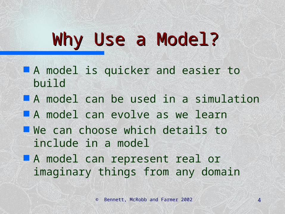
© Bennett, McRobb and Farmer 2002 4
Why Use a Model?Why Use a Model?
A model is quicker and easier to build
A model can be used in a simulation A model can evolve as we learn We can choose which details to
include in a model A model can represent real or
imaginary things from any domain

© Bennett, McRobb and Farmer 2002 5
Modelling OrganizationsModelling Organizations
Organizations are human activity systems.
The situation is complex Stakeholders have different views We have to model requirements
accurately, completely and unambiguously
The model must not prejudge the solution
© Bennett, McRobb and Farmer 2002 6
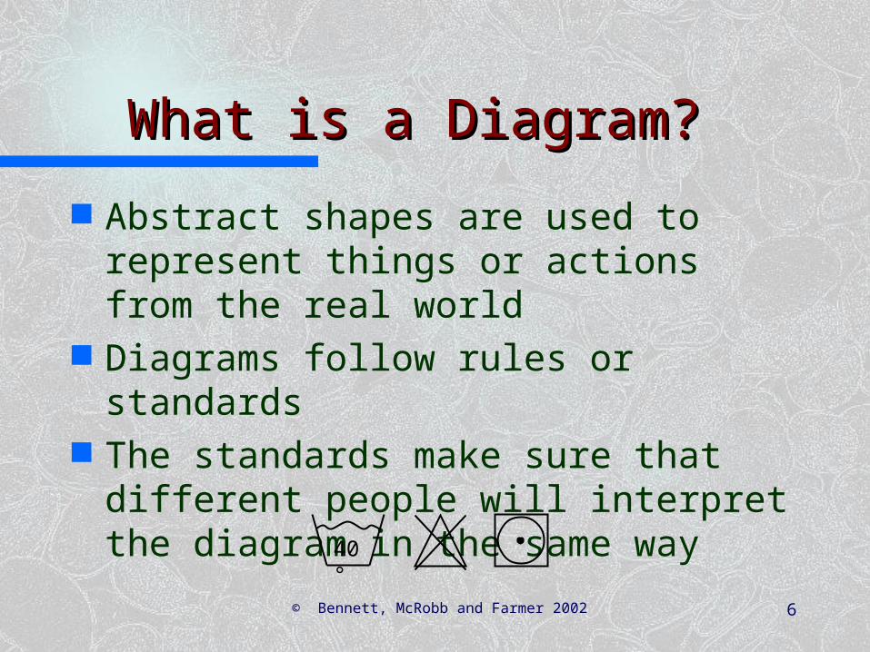
What is a Diagram?What is a Diagram?
Abstract shapes are used to represent things or actions from the real world
Diagrams follow rules or standards The standards make sure that
different people will interpret the diagram in the same way
40°

© Bennett, McRobb and Farmer 2002 7
An Example An Example of a Diagramof a Diagram
An activity diagram of the tasks involved in producing a book.
Write Chapter
Review Chapter
Author PrinterTypesetterReviewer
Typeset Book
Correct Proofs
Reset Book
Print Book
[book complete]
[book notcomplete]
Revise Chapter

© Bennett, McRobb and Farmer 2002 8
Write Chapter
Review Chapter
Author PrinterTypesetterReviewer
Typeset Book
Correct Proofs
Reset Book
Print Book
[book complete]
[book notcomplete]
Revise Chapter
Hiding Hiding DetailDetail
Plan Chapter
Produce First Draft
Revise Draft
[satisfied]
[not satisfied]
Add Exercises
Add Referencesto Bibliography
Write Chapter

© Bennett, McRobb and Farmer 2002 9
Diagrams in UMLDiagrams in UML
UML diagrams consist of:– icons– two-dimensional symbols– paths– Strings
UML diagrams are defined inthe UML specification.
Plan Chapter
Produce First Draft
Revise Draft
[satisfied]
[not satisfied]
Add Exercises
Add Referencesto Bibliography
Write Chapter
© Bennett, McRobb and Farmer 2002 10
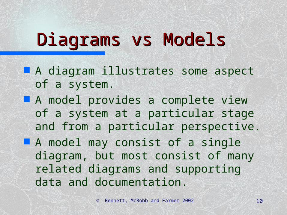
Diagrams vs Models Diagrams vs Models
A diagram illustrates some aspect of a system.
A model provides a complete view of a system at a particular stage and from a particular perspective.
A model may consist of a single diagram, but most consist of many related diagrams and supporting data and documentation.

© Bennett, McRobb and Farmer 2002 11
Examples of ModelsExamples of Models
Requirements Model– complete view of requirements– may include other models, such as a
Use Case Model– includes textual description as well as
sets of diagrams

© Bennett, McRobb and Farmer 2002 12
Examples of ModelsExamples of Models
Behavioural Model– shows how the system responds to
events in the outside world and the passage of time
– an initial model may just use Collaboration Diagrams
– a later model will include Sequence Diagrams and Statecharts

© Bennett, McRobb and Farmer 2002 13
Models in UMLModels in UML
A system is the overall thing that is being modelled
A sub-system is a part of a system consisting of related elements
A model is an abstraction of a system or sub-system from a particular perspective
A model is complete and consistent at the chosen level of abstraction
© Bennett, McRobb and Farmer 2002 14
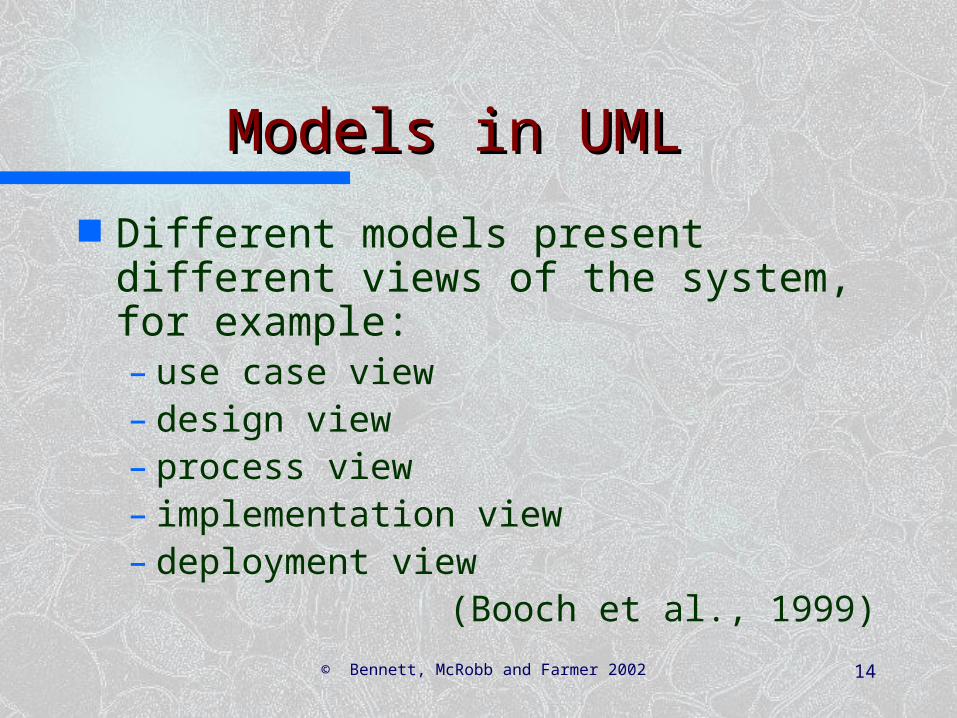
Models in UMLModels in UML
Different models present different views of the system, for example:– use case view– design view– process view– implementation view– deployment view
(Booch et al., 1999)

© Bennett, McRobb and Farmer 2002 15
Packages, Sub-systems and Packages, Sub-systems and ModelsModels
UML has notation for showing sub-systems and models, and also for packages, which are a mechanism for organising models (e.g. in CASE tools)
Use Cases Use CaseModel
CampaignManagement
Package ModelSub-system

© Bennett, McRobb and Farmer 2002 16
Developing ModelsDeveloping Models
During the life of a project using an iterative life cycle, models change along the dimensions of:– abstraction—they become more
concrete– formality—they become more formally
specified– level of detail—additional detail is
added as understanding improves

© Bennett, McRobb and Farmer 2002 17
Development of the Use Development of the Use Case ModelCase Model
Iteration 1Obvious use cases.Simple use case descriptions.
Iteration 2Additional use cases.Simple use case descriptions.Prototypes.
Iteration 3Structured use cases.Structured use case descriptions.Prototypes.
Assign staff to work on
a campaign
Campaign Manager
Add a new advert to
a campaign
Check campaign budget
Find campaign
Accountant
summary Print campaign
invoice
«include»
«extend» «extend»
Print campaign
«include»
«include»
Campaign Management
Assign staff to work on
a campaign
Campaign Manager
Add a new advert to
a campaign
Check campaign budget
Find campaign
Accountant
summary Print campaign
invoice
«include»
«extend» «extend»
Print campaign
«include»
«include»
Campaign Management
Calculate staff bonuses
Accountant
Add a new staff member
Add a new staff grade
Change the rate for a
staff grade
Change the grade for a
staff member
Staff Management
Calculate staff bonuses
Accountant
Add a new staff member
Add a new staff grade
Change the rate for a
staff grade
Change the grade for a
staff member
Staff Management
Calculate staff bonuses
Accountant
Add a new staff member
Add a new staff grade
Change the rate for a
staff grade
Change the grade for a
staff member
Staff Management
Calculate staff bonuses
Accountant
Add a new staff member
Add a new staff grade
Change the rate for a
staff grade
Change the grade for a
staff member
Staff Management
Calculate staff bonuses
Accountant
Add a new staff member
Add a new staff grade
Change the rate for a
staff grade
Change the grade for a
staff member
Staff Management
Assign staff to work on
a campaign
Campaign Manager
Add a new advert to
a campaign
Check campaign budget
Find campaign
Accountant
summary Print campaign
invoice
«include»
«extend» «extend»
Print campaign
«include»
«include»
Campaign Management
Spring Jewellery Campaign 1997Spring Jewellery Campaign 2001Spring Jewellery Campaign 2002Summer Collection 1998
OK Quit
Campaign:
Campaign Selection
Holborn MotorsLynch PropertiesYellow Partridge Zeta Systems
Client:
Yellow Partridge
Spring Jewellery Campaign 1997Spring Jewellery Campaign 2001Spring Jewellery Campaign 2002Summer Collection 1998
OK Quit
Campaign:
Campaign Selection
Holborn MotorsLynch PropertiesYellow Partridge Zeta Systems
Client:
Yellow Partridge
Spring Jewellery Campaign 2002
OK Quit
Campaign:
Campaign Selection
Holborn MotorsLynch PropertiesYellow Partridge Zeta Systems
Client:
Spring Jewellery Campaign 1997Spring Jewellery Campaign 2001Spring Jewellery Campaign 2002Summer Collection 1998
OK Quit
Campaign:
Campaign Selection
Holborn MotorsLynch PropertiesYellow Partridge Zeta Systems
Client:
Yellow Partridge
Spring Jewellery Campaign 1997Spring Jewellery Campaign 2001Spring Jewellery Campaign 2002Summer Collection 1998
OK Quit
Campaign:
Campaign Selection
Holborn MotorsLynch PropertiesYellow Partridge Zeta Systems
Client:
Yellow Partridge
Spring Jewellery Campaign 2002
OK Quit
Campaign:
Campaign Selection
Holborn MotorsLynch PropertiesYellow Partridge Zeta Systems
Client:
© Bennett, McRobb and Farmer 2002 18
SummarySummary
In this lecture you have learned about:
What is meant by a model The distinction between a model
and a diagram The UML concept of a model
© Bennett, McRobb and Farmer 2002 19
ReferencesReferences
Booch, Rumbaugh and Jacobson (1999)
(For full bibliographic details, see Bennett, McRobb and Farmer)

03/12/2001 © Bennett, McRobb and Farmer 2002 20
Activity DiagramsActivity Diagrams
Based on Chapter 5 of Bennett, McRobb and Farmer: Object Oriented Systems Analysis and Design Using UML, (2nd Edition), McGraw Hill, 2002.

© Bennett, McRobb and Farmer 2002 21
In This Lecture You Will In This Lecture You Will Learn:Learn:
The purpose of activity diagrams The notation of activity diagrams How to draw activity diagrams

© Bennett, McRobb and Farmer 2002 22
Drawing Activity DiagramsDrawing Activity Diagrams
Purpose– to model a task (for example in
business modelling)– to describe a function of a system
represented by a use case– to describe the logic of an operation– to model the activities that make up
the life cycle in the Unified Process

© Bennett, McRobb and Farmer 2002 23
Notation of Activity Notation of Activity DiagramsDiagrams
Activities– rectangle with rounded ends– meaningful name
Transitions– arrows with open
arrowheads
Add a New Client
Assign StaffContact

© Bennett, McRobb and Farmer 2002 24
Notation of Activity Notation of Activity DiagramsDiagrams
Start state– black circle
Decision points– diamond
Guard conditions– in square brackets
Final state– black circle in white circle
[campaign to add]
[no campaign to add]
Add a New Client
Assign StaffContact
Add New Campaign
© Bennett, McRobb and Farmer 2002 25
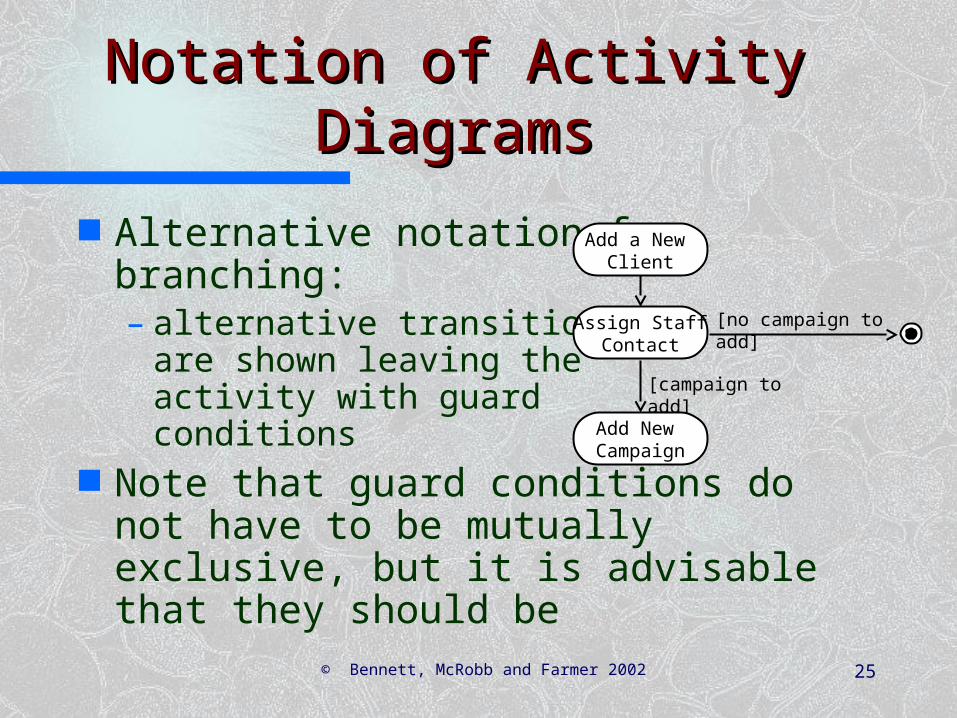
Notation of Activity Notation of Activity DiagramsDiagrams
Alternative notation for branching:– alternative transitions
are shown leaving theactivity with guardconditions
Note that guard conditions do not have to be mutually exclusive, but it is advisable that they should be
[campaign to add]
[no campaign to add]
Add a New Client
Assign StaffContact
Add New Campaign
© Bennett, McRobb and Farmer 2002 26
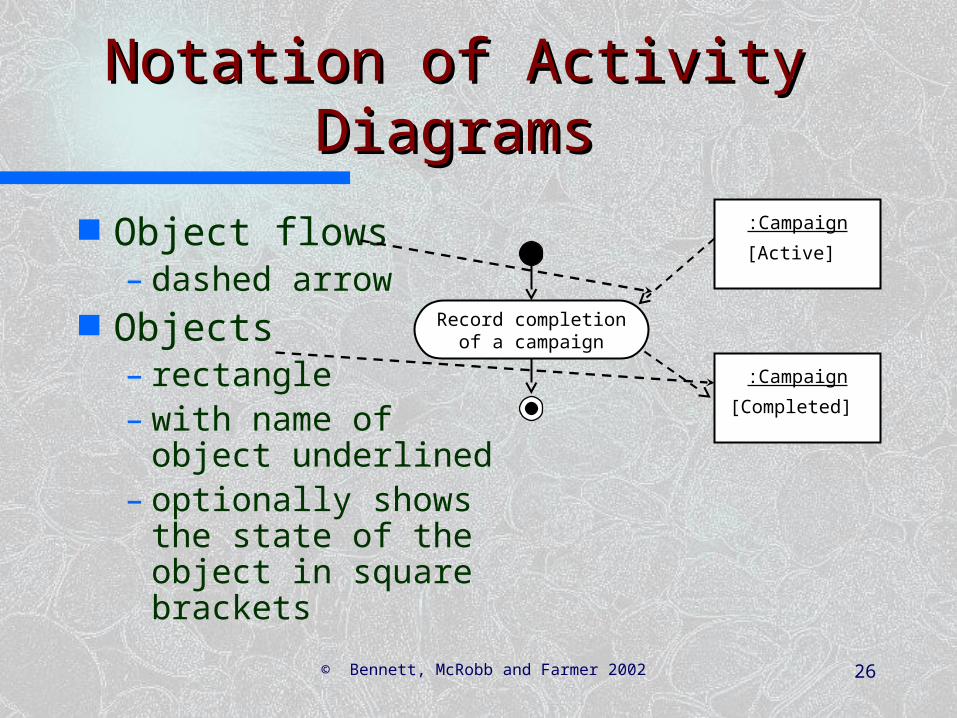
Notation of Activity Notation of Activity DiagramsDiagrams
Object flows– dashed arrow
Objects– rectangle– with name of object
underlined– optionally shows
the state of the object in square brackets
Record completionof a campaign
:Campaign
[Active]
:Campaign
[Completed]

© Bennett, McRobb and Farmer 2002 27
Notation of Activity Notation of Activity DiagramsDiagrams
Swimlanes– vertical columns – labelled with the
person, organisationor departmentresponsible for theactivities in thatcolumn
Record Completionof a campaign
Issue invoice
CampaignManager
ClientAccountant
Pay invoice
Record clientpayment
© Bennett, McRobb and Farmer 2002 28
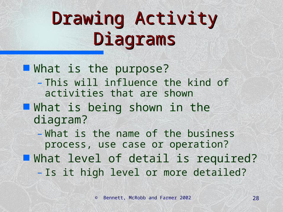
Drawing Activity DiagramsDrawing Activity Diagrams
What is the purpose?– This will influence the kind of
activities that are shown What is being shown in the
diagram?– What is the name of the business
process, use case or operation? What level of detail is required?
– Is it high level or more detailed?

© Bennett, McRobb and Farmer 2002 29
Drawing Activity DiagramsDrawing Activity Diagrams
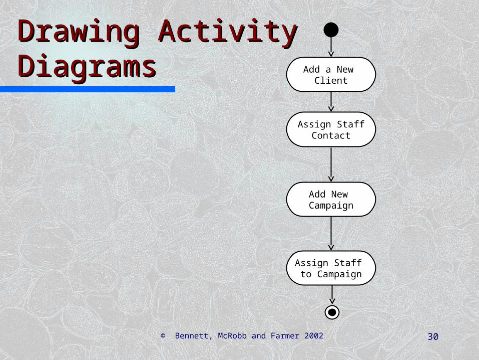
Identify activities– What happens when a new client is
added in the Agate system? Add a New Client Assign Staff Contact Add New Campaign Assign Staff to Campaign
Organise the activities in order with transitions
© Bennett, McRobb and Farmer 2002 30
Drawing Activity Drawing Activity DiagramsDiagrams Add a New
Client
Assign StaffContact
Add New Campaign
Assign Staff to Campaign

© Bennett, McRobb and Farmer 2002 31
Drawing Activity DiagramsDrawing Activity Diagrams
Identify any alternative transitions and the conditions on them– sometimes there is a new campaign
to add for a new client, sometimes not– sometimes they will want to assign
staff to the campaign, sometimes not Add transitions and guard
conditions to the diagram

© Bennett, McRobb and Farmer 2002 32
Drawing Activity Drawing Activity DiagramsDiagrams
[no staff to assign]
Add a New Client
Assign StaffContact
Add New Campaign
[campaign to add]
[no campaign to add]
Assign Staff to Campaign
[staff to assign]

© Bennett, McRobb and Farmer 2002 33
Drawing Activity DiagramsDrawing Activity Diagrams
Identify any processes that are repeated– they will want to assign staff to the
campaign until there are no more staff to add
Add transitions and guard conditions to the diagram

© Bennett, McRobb and Farmer 2002 34
Drawing Activity Drawing Activity DiagramsDiagrams
[no staff to assign]
[no more staff to assign]
Add a New Client
Assign StaffContact
Add New Campaign
[campaign to add]
[no campaign to add]
Assign Staff to Campaign
[staff to assign]
[more staff to assign]

© Bennett, McRobb and Farmer 2002 35
Drawing Activity DiagramsDrawing Activity Diagrams
Are all the activities carried out by the same person, organisation or department?
If not, then add swimlanes to show the responsibilities
Name the swimlanes Show each activity in the
appropriate swimlane

© Bennett, McRobb and Farmer 2002 36
[no staff to assign]
Add a New Client
Assign StaffContact
Add New Campaign
[campaign to add]
[no campaign to add]
Assign Staff to Campaign
[staff to assign]
Campaign ManagerAdministrator

© Bennett, McRobb and Farmer 2002 37
Drawing Activity DiagramsDrawing Activity Diagrams
Are there any object flows and objects to show?– these can be documents that are
created or updated in a business activity diagram
– these can be object instances that change state in an operation or a use case
Add the object flows and objects

© Bennett, McRobb and Farmer 2002 38
[no staff to assign]
Add a New Client
Assign StaffContact
Add New Campaign
[campaign to add]
[no campaign to add]
Assign Staff to Campaign
[staff to assign]
Campaign ManagerAdministrator
:Campaign
[Commissioned]
:Client[New]

© Bennett, McRobb and Farmer 2002 39
SummarySummary
In this lecture you have learned about:
The purpose of activity diagrams The notation of activity diagrams How to draw activity diagrams

© Bennett, McRobb and Farmer 2002 40
ReferencesReferences
Booch, Rumbaugh and Jacobson (1999)
Rumbaugh, Jacobson and Booch (1999)
(For full bibliographic details, see Bennett, McRobb and Farmer)

03/12/2001 © Bennett, McRobb and Farmer 2002 41
Development ProcessDevelopment Process
Based on Chapter 5 of Bennett, McRobb and Farmer: Object Oriented Systems Analysis and Design Using UML, (2nd Edition), McGraw Hill, 2002.
© Bennett, McRobb and Farmer 2002 42
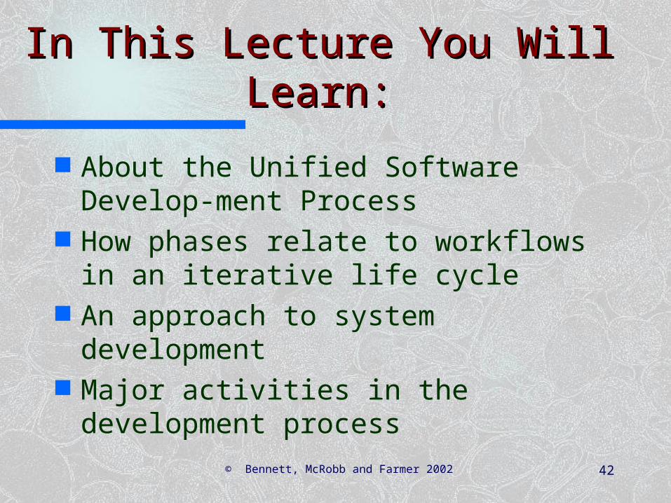
In This Lecture You Will In This Lecture You Will Learn:Learn:
About the Unified Software Develop-ment Process
How phases relate to workflows in an iterative life cycle
An approach to system development
Major activities in the development process

© Bennett, McRobb and Farmer 2002 43
Unified Software Unified Software Development ProcessDevelopment Process
Developed by the team that created UML
Embodies best practice in system development
Adopts an iterative approach with four main phases
Different tasks are captured in a series of workflows

© Bennett, McRobb and Farmer 2002 44
Best PracticeBest Practice
Iterative and incremental development
Component-based development Requirements-driven development Configurability Architecture-centrism Visual modelling techniques
© Bennett, McRobb and Farmer 2002 45
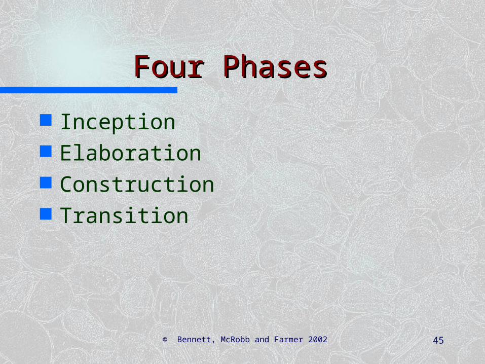
Four PhasesFour Phases
Inception Elaboration Construction Transition

© Bennett, McRobb and Farmer 2002 46
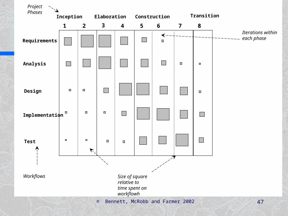
Phases, Workflows Phases, Workflows and Iterationsand Iterations
Within each phase activities are grouped into workflows
The balance of effort spent in each workflow varies from phase to phase
Within phases there may be more than one iteration
© Bennett, McRobb and Farmer 2002 47
Size of square relative to time spent on workflowh
Inception Elaboration Construction Transition
Project Phases
1 2 3 4 5 6 7 8Iterations within each phase
Requirements
Analysis
Design
Implementation
Test
Workflows
© Bennett, McRobb and Farmer 2002 48
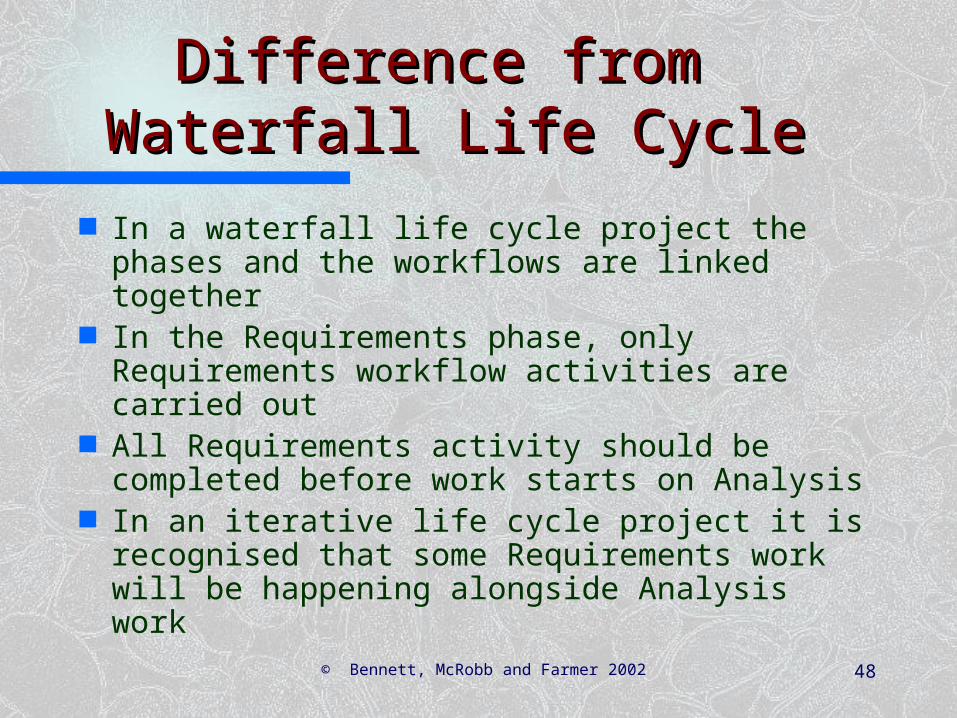
Difference from Difference from Waterfall Life CycleWaterfall Life Cycle
In a waterfall life cycle project the phases and the workflows are linked together
In the Requirements phase, only Requirements workflow activities are carried out
All Requirements activity should be completed before work starts on Analysis
In an iterative life cycle project it is recognised that some Requirements work will be happening alongside Analysis work

© Bennett, McRobb and Farmer 2002 49
Requirements
Analysis
Design
Implementation
Test
Requirements
Analysis
Design
Implementation
Test

© Bennett, McRobb and Farmer 2002 50
Major Activities of the Major Activities of the Development ProcessDevelopment Process
Activity Techniques Key Deliverables
Requirements Capture and Modelling
Requirements ElicitationUse Case ModellingPrototyping
Use Case ModelRequirements ListPrototypesGlossary

© Bennett, McRobb and Farmer 2002 51
Major Activities of the Major Activities of the Development ProcessDevelopment Process
Activity Techniques Key Deliverables
Requirements Analysis
Collaboration DiagramsClass and Object ModelsAnalysis Modelling
Analysis Models
© Bennett, McRobb and Farmer 2002 52
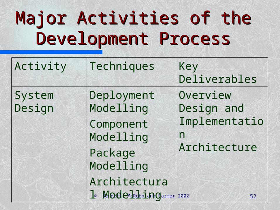
Major Activities of the Major Activities of the Development ProcessDevelopment Process
Activity Techniques Key Deliverables
System Design
Deployment ModellingComponent ModellingPackage ModellingArchitectural Modelling
Overview Design and Implementation Architecture

© Bennett, McRobb and Farmer 2002 53
Major Activities of the Major Activities of the Development ProcessDevelopment Process
Activity Techniques Key Deliverables
Class Design
Class and Object ModellingInteraction ModellingState ModellingDesign Patterns
Design Models

© Bennett, McRobb and Farmer 2002 54
Major Activities of the Major Activities of the Development ProcessDevelopment Process
Activity Techniques Key Deliverables
User Interface Design
Class and Object ModellingInteraction ModellingState ModellingPackage ModellingPrototypingDesign Patterns
Design Models with Interface Specification

© Bennett, McRobb and Farmer 2002 55
Major Activities of the Major Activities of the Development ProcessDevelopment Process
Activity Techniques Key Deliverables
Data Management Design
Class and Object ModellingInteraction ModellingState ModellingPackage ModellingDesign Patterns
Design Models with Database Specification
© Bennett, McRobb and Farmer 2002 56
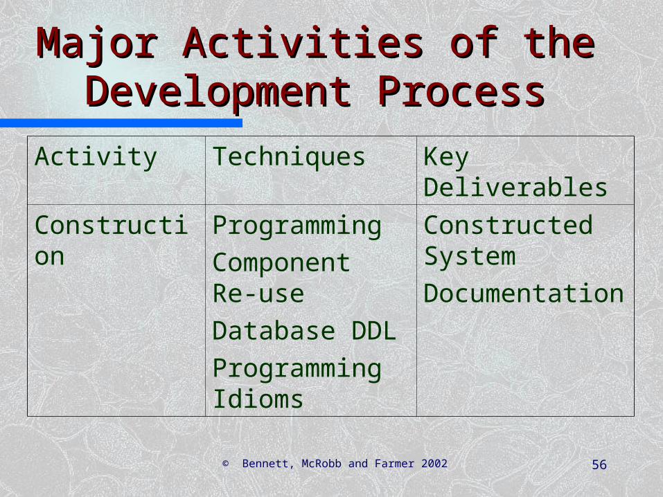
Major Activities of the Major Activities of the Development ProcessDevelopment Process
Activity Techniques Key Deliverables
Construction ProgrammingComponent Re-useDatabase DDLProgramming Idioms
Constructed SystemDocumentation

© Bennett, McRobb and Farmer 2002 57
Major Activities of the Major Activities of the Development ProcessDevelopment Process
Activity Techniques Key Deliverables
Testing ProgrammingTest Procedures
Tested System

© Bennett, McRobb and Farmer 2002 58
Major Activities of the Major Activities of the Development ProcessDevelopment Process
Activity Techniques Key Deliverables
Implementation
Installed System

© Bennett, McRobb and Farmer 2002 59
SummarySummary
In this lecture you have learned about: The Unified Software Development
Process How phases relate to workflows in an
iterative life cycle An approach to system development Major activities in the development
process

© Bennett, McRobb and Farmer 2002 60
ReferencesReferences
Jacobson, Booch and Rumbaugh (1999)
Kruchten (1999) Chapter 22 of Bennett, McRobb
and Farmer includes more detail about the Unified Process
(For full bibliographic details, see Bennett, McRobb and Farmer)