03002 manual
TRANSCRIPT
INST
RU
CT
ION
MA
NU
AL
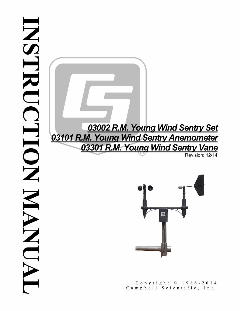
03002 R.M. Young Wind Sentry Set 03101 R.M. Young Wind Sentry Anemometer
03301 R.M. Young Wind Sentry Vane Revision: 12/14
C o p y r i g h t © 1 9 8 6 - 2 0 1 4 C a m p b e l l S c i e n t i f i c , I n c .


Limited Warranty “Products manufactured by CSI are warranted by CSI to be free from defects in materials and workmanship under normal use and service for twelve months from the date of shipment unless otherwise specified in the corresponding product manual. (Product manuals are available for review online at www.campbellsci.com.) Products not manufactured by CSI, but that are resold by CSI, are warranted only to the limits extended by the original manufacturer. Batteries, fine-wire thermocouples, desiccant, and other consumables have no warranty. CSI’s obligation under this warranty is limited to repairing or replacing (at CSI’s option) defective Products, which shall be the sole and exclusive remedy under this warranty. The Customer assumes all costs of removing, reinstalling, and shipping defective Products to CSI. CSI will return such Products by surface carrier prepaid within the continental United States of America. To all other locations, CSI will return such Products best way CIP (port of entry) per Incoterms ® 2010. This warranty shall not apply to any Products which have been subjected to modification, misuse, neglect, improper service, accidents of nature, or shipping damage. This warranty is in lieu of all other warranties, expressed or implied. The warranty for installation services performed by CSI such as programming to customer specifications, electrical connections to Products manufactured by CSI, and Product specific training, is part of CSI's product warranty. CSI EXPRESSLY DISCLAIMS AND EXCLUDES ANY IMPLIED WARRANTIES OF MERCHANTABILITY OR FITNESS FOR A PARTICULAR PURPOSE. CSI hereby disclaims, to the fullest extent allowed by applicable law, any and all warranties and conditions with respect to the Products, whether express, implied or statutory, other than those expressly provided herein.”

Assistance Products may not be returned without prior authorization. The following contact information is for US and international customers residing in countries served by Campbell Scientific, Inc. directly. Affiliate companies handle repairs for customers within their territories. Please visit www.campbellsci.com to determine which Campbell Scientific company serves your country.
To obtain a Returned Materials Authorization (RMA), contact CAMPBELL SCIENTIFIC, INC., phone (435) 227-9000. After an application engineer determines the nature of the problem, an RMA number will be issued. Please write this number clearly on the outside of the shipping container. Campbell Scientific’s shipping address is:
CAMPBELL SCIENTIFIC, INC. RMA#_____ 815 West 1800 North Logan, Utah 84321-1784
For all returns, the customer must fill out a “Statement of Product Cleanliness and Decontamination” form and comply with the requirements specified in it. The form is available from our web site at www.campbellsci.com/repair. A completed form must be either emailed to [email protected] or faxed to (435) 227-9106. Campbell Scientific is unable to process any returns until we receive this form. If the form is not received within three days of product receipt or is incomplete, the product will be returned to the customer at the customer’s expense. Campbell Scientific reserves the right to refuse service on products that were exposed to contaminants that may cause health or safety concerns for our employees.

Precautions DANGER — MANY HAZARDS ARE ASSOCIATED WITH INSTALLING, USING, MAINTAINING, AND WORKING ON OR AROUND TRIPODS, TOWERS, AND ANY ATTACHMENTS TO TRIPODS AND TOWERS SUCH AS SENSORS, CROSSARMS, ENCLOSURES, ANTENNAS, ETC. FAILURE TO PROPERLY AND COMPLETELY ASSEMBLE, INSTALL, OPERATE, USE, AND MAINTAIN TRIPODS, TOWERS, AND ATTACHMENTS, AND FAILURE TO HEED WARNINGS, INCREASES THE RISK OF DEATH, ACCIDENT, SERIOUS INJURY, PROPERTY DAMAGE, AND PRODUCT FAILURE. TAKE ALL REASONABLE PRECAUTIONS TO AVOID THESE HAZARDS. CHECK WITH YOUR ORGANIZATION'S SAFETY COORDINATOR (OR POLICY) FOR PROCEDURES AND REQUIRED PROTECTIVE EQUIPMENT PRIOR TO PERFORMING ANY WORK.
Use tripods, towers, and attachments to tripods and towers only for purposes for which they are designed. Do not exceed design limits. Be familiar and comply with all instructions provided in product manuals. Manuals are available at www.campbellsci.com or by telephoning (435) 227-9000 (USA). You are responsible for conformance with governing codes and regulations, including safety regulations, and the integrity and location of structures or land to which towers, tripods, and any attachments are attached. Installation sites should be evaluated and approved by a qualified engineer. If questions or concerns arise regarding installation, use, or maintenance of tripods, towers, attachments, or electrical connections, consult with a licensed and qualified engineer or electrician. General
• Prior to performing site or installation work, obtain required approvals and permits. Comply with all governing structure-height regulations, such as those of the FAA in the USA.
• Use only qualified personnel for installation, use, and maintenance of tripods and towers, and any attachments to tripods and towers. The use of licensed and qualified contractors is highly recommended.
• Read all applicable instructions carefully and understand procedures thoroughly before beginning work.
• Wear a hardhat and eye protection, and take other appropriate safety precautions while working on or around tripods and towers.
• Do not climb tripods or towers at any time, and prohibit climbing by other persons. Take reasonable precautions to secure tripod and tower sites from trespassers.
• Use only manufacturer recommended parts, materials, and tools.
Utility and Electrical • You can be killed or sustain serious bodily injury if the tripod, tower, or attachments you are
installing, constructing, using, or maintaining, or a tool, stake, or anchor, come in contact with overhead or underground utility lines.
• Maintain a distance of at least one-and-one-half times structure height, 20 feet, or the distance required by applicable law, whichever is greater, between overhead utility lines and the structure (tripod, tower, attachments, or tools).
• Prior to performing site or installation work, inform all utility companies and have all underground utilities marked.
• Comply with all electrical codes. Electrical equipment and related grounding devices should be installed by a licensed and qualified electrician.
Elevated Work and Weather • Exercise extreme caution when performing elevated work. • Use appropriate equipment and safety practices. • During installation and maintenance, keep tower and tripod sites clear of un-trained or non-
essential personnel. Take precautions to prevent elevated tools and objects from dropping. • Do not perform any work in inclement weather, including wind, rain, snow, lightning, etc.
Maintenance • Periodically (at least yearly) check for wear and damage, including corrosion, stress cracks,
frayed cables, loose cable clamps, cable tightness, etc. and take necessary corrective actions. • Periodically (at least yearly) check electrical ground connections.
WHILE EVERY ATTEMPT IS MADE TO EMBODY THE HIGHEST DEGREE OF SAFETY IN ALL CAMPBELL SCIENTIFIC PRODUCTS, THE CUSTOMER ASSUMES ALL RISK FROM ANY INJURY RESULTING FROM IMPROPER INSTALLATION, USE, OR MAINTENANCE OF TRIPODS, TOWERS, OR ATTACHMENTS TO TRIPODS AND TOWERS SUCH AS SENSORS, CROSSARMS, ENCLOSURES, ANTENNAS, ETC.

Table of Contents PDF viewers: These page numbers refer to the printed version of this document. Use the PDF reader bookmarks tab for links to specific sections.
1. Introduction ................................................................. 1
2. Cautionary Statements ............................................... 1
3. Initial Inspection ......................................................... 1
3.1 Ships With List .................................................................................... 2
4. Quickstart .................................................................... 2
4.1 Step 1—Mount the Sensor ................................................................... 2 4.2 Step 2 — Use SCWin Short Cut to Program Datalogger and
Generate Wiring Diagram ................................................................. 5
5. Overview ...................................................................... 7
6. Specifications ............................................................. 8
6.1 Wind Speed (Anemometer).................................................................. 9 6.2 Wind Direction (Vane) ......................................................................... 9 6.3 Wind Sentry Assembly ........................................................................ 9
7. Installation ................................................................... 9
7.1 Siting .................................................................................................. 10 7.2 Assembly and Mounting .................................................................... 10
7.2.1 03002 Wind Sentry Set ............................................................... 10 7.2.2 03101 Anemometer ..................................................................... 10 7.2.3 03301 Vane ................................................................................. 11
7.3 Wiring ................................................................................................ 12 7.4 Programming ...................................................................................... 13
7.4.1 Wind Speed ................................................................................. 13 7.4.2 Wind Direction ........................................................................... 14 7.4.3 Wind Vector Processing Instruction ........................................... 14 7.4.4 Long Lead Lengths ..................................................................... 15
8. Sensor Maintenance ................................................. 15
9. Troubleshooting........................................................ 15
9.1 Wind Direction ................................................................................... 15 9.2 Wind Speed ........................................................................................ 16
10. References ................................................................ 16
i
Table of Contents
Appendices
A. Importing Short Cut Code ...................................... A-1
A.1 Importing Short Cut Code into a Program Editor ............................ A-1
B. Example Programs .................................................. B-1
C. Wind Direction Sensor Orientation ....................... C-1
C.1 Determining True North and Sensor Orientation ............................ C-1
D. Wind Direction Measurement Theory .................... D-1
D.1 BRHalf Instruction .......................................................................... D-1
Figures 4-1. CM200-Series Crossarm with CM220 Right Angle Mounting
Bracket ............................................................................................. 3 4-2. 03002 mounted to CM200-Series Crossarm with CM220 .................. 4 4-3. 03002 mounted to a crossarm with pn 17953 ...................................... 4 7-1. The CM216 allows an 03002 or 03101 to mount atop the mast of
a CM110, CM115, or CM120 tripod ............................................. 10 7-2. 03101 mounted to a crossarm via a 1049 NU-RAIL ......................... 11 C-1. Magnetic declination for the contiguous United States (2004) ....... C-2 C-2. Declination angles east of True North are subtracted from 0 to
get True North .............................................................................. C-3 C-3. Declination angles west of True North are added to 0 to get
True North ................................................................................... C-3 D-1. 03002 and 03301 potentiometer in a half bridge circuit .................. D-1
Tables 5-1. Recommended Cable Lengths ............................................................. 8 7-1. 03002-L Wiring ................................................................................. 12 7-2. 03101 and 03301 Wiring ................................................................... 12 7-3. Wind Speed Multiplier (With Pulse Channel Configuration Set
to Low Level AC, Output “Hz”) .................................................... 14 7-4. Parameters for Wind Direction .......................................................... 14 B-1. Wiring for Example Programs using the 03002-L .......................... B-1
ii
R.M. Young Wind Sentry 1. Introduction
The 03002 Wind Sentry Set measures both wind speed and direction. It consists of a 3-cup anemometer and a wind vane mounted on a small crossarm. The anemometer (pn 03101) and vane (pn 03301) may be purchased separately.
This manual provides information only for CRBasic dataloggers. It is also compatible with the most of our retired Edlog dataloggers. For Edlog datalogger support, see an older manual at www.campbellsci.com/old-manuals or contact a Campbell Scientific application engineer for assistance.
2. Cautionary Statements • READ AND UNDERSTAND the Precautions section at the front of this
manual.
• The 03002 is a precision instrument. Please handle it with care.
• If the 03002 is to be installed at heights over 6 feet, be familiar with tower safety and follow safe tower climbing procedures.
• Danger — Use extreme care when working near overhead electrical wires. Check for overhead wires before mounting the 03002 or before raising a tower.
• The black outer jacket of the cable is Santoprene® rubber. This compound was chosen for its resistance to temperature extremes, moisture, and UV degradation. However, this jacket will support combustion in air. It is rated as slow burning when tested according to U.L. 94 H.B. and will pass FMVSS302. Local fire codes may preclude its use inside buildings.
3. Initial Inspection • Upon receipt of the 03002, inspect the packaging and contents for damage.
File damage claims with the shipping company. Immediately check package contents against the shipping documentation (see Section 3.1, Ships With List). Contact Campbell Scientific about any discrepancies.
• The model number and cable length are printed on a label at the connection end of the cable. Check this information against the shipping documents to ensure the expected product and cable length are received.
NOTE
1

R.M. Young Wind Sentry
3.1 Ships With List The 03002 Wind Sentry ships with:
(1) 03002 Wind Sentry including 03102 anemometer 03302 vane crossarm band clamp (pn 4919) (1) 1 inch IPS, 12 inch long, unthreaded aluminum pipe (pn 3659) (1) Allen wrench (pn 5201)
The 03101 anemometer ships with:
(1) 03101 anemometer (1) 3/4 inch IPS, 10 inch long, threaded aluminum pipe (pn 7623) (1) Allen wrench (pn 5201)
The 03301 vane ships with:
(1) 03301 vane (1) 3/4 inch IPS, 10 inch long threaded aluminum pipe (pn 7623); this assumes mounting option –P. (1) Allen wrench (pn 5201)
4. Quickstart 4.1 Step 1—Mount the Sensor
This quick start is for the 03002 wind set. Refer to Section 7, Installation, if installing just the 03101 anemometer or 03301 vane. Section 7, Installation, also provides siting information.
Tools required:
• 5/64 inch Allen wrench • Allen wrench provided with sensor • 1/2 inch open end wrench • compass and declination angle for the site (see Appendix C) • small screw driver provided with datalogger • UV resistant cable ties • small pair of diagonal-cutting pliers • 6 inch to 10 inch torpedo level
Install the 03002 using:
• Standard 1.0-in. IPS schedule 40 pipe (pn 3659) • CM220 Right-Angle Mounting Kit (FIGURE 4-1 and FIGURE 4-2),
or • 17953 1 x 1 inch NU-RAIL Crossover Fitting (FIGURE 4-3)
2
R.M. Young Wind Sentry
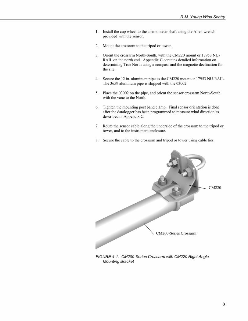
1. Install the cup wheel to the anemometer shaft using the Allen wrench provided with the sensor.
2. Mount the crossarm to the tripod or tower.
3. Orient the crossarm North-South, with the CM220 mount or 17953 NU-RAIL on the north end. Appendix C contains detailed information on determining True North using a compass and the magnetic declination for the site.
4. Secure the 12 in. aluminum pipe to the CM220 mount or 17953 NU-RAIL. The 3659 aluminum pipe is shipped with the 03002.
5. Place the 03002 on the pipe, and orient the sensor crossarm North-South with the vane to the North.
6. Tighten the mounting post band clamp. Final sensor orientation is done after the datalogger has been programmed to measure wind direction as described in Appendix C.
7. Route the sensor cable along the underside of the crossarm to the tripod or tower, and to the instrument enclosure.
8. Secure the cable to the crossarm and tripod or tower using cable ties.
FIGURE 4-1. CM200-Series Crossarm with CM220 Right Angle Mounting Bracket
CM220
CM200-Series Crossarm
3

R.M. Young Wind Sentry
FIGURE 4-2. 03002 mounted to CM200-Series Crossarm with CM220
FIGURE 4-3. 03002 mounted to a crossarm with pn 17953
CM220
CM200-Series Crossarm
Aluminum Pipe
CM200-Series Crossarm
Aluminum Pipe
Cable Tie
pn 17953 NU-RAIL
4

R.M. Young Wind Sentry
4.2 Step 2 — Use SCWin Short Cut to Program Datalogger and Generate Wiring Diagram
The simplest method for programming the datalogger to measure the 034B is to Short Cut is an easy way to program your datalogger to measure the 014A and assign datalogger wiring terminals. The following procedure shows using Short Cut to program the 014A.
9. Install Short Cut by clicking on the install file icon. Get the install file from either www.campbellsci.com, the ResourceDVD, or find it in installations of LoggerNet, PC200W, PC400, or RTDAQ software.
10. The Short Cut installation should place a shortcut icon on the desktop of your computer. To open Short Cut, click on this icon.
11. When Short Cut opens, select New Program.
5
R.M. Young Wind Sentry
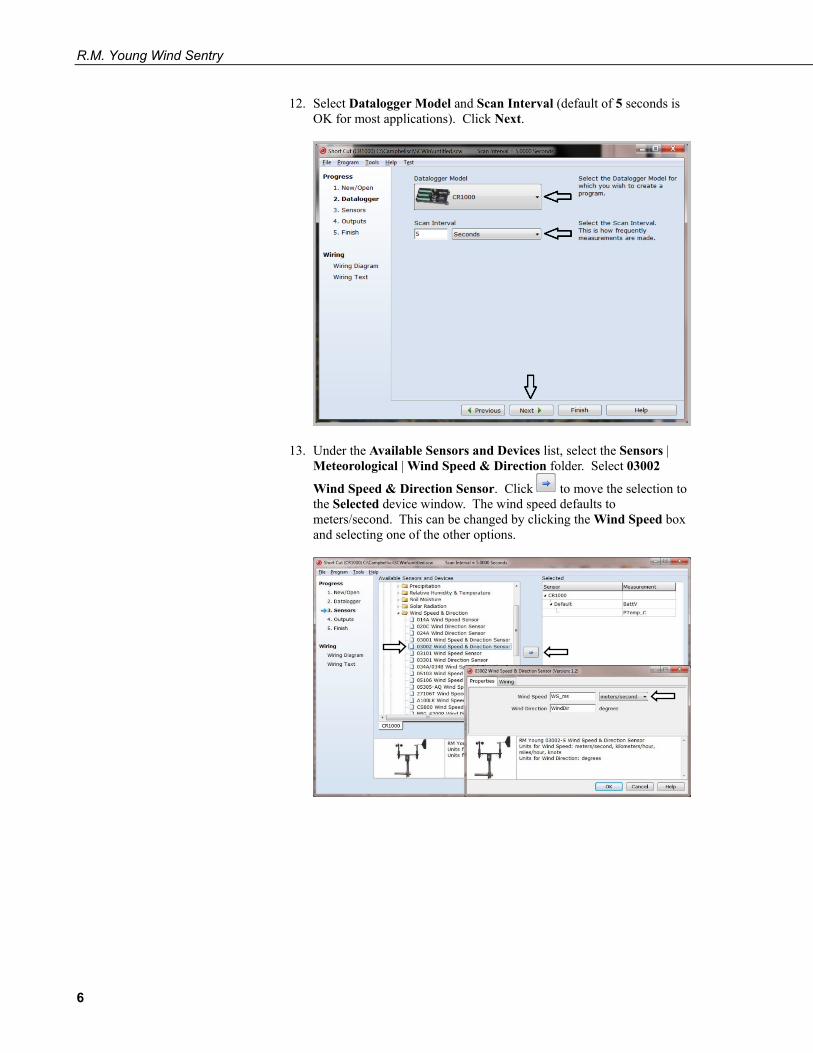
12. Select Datalogger Model and Scan Interval (default of 5 seconds is OK for most applications). Click Next.
13. Under the Available Sensors and Devices list, select the Sensors | Meteorological | Wind Speed & Direction folder. Select 03002
Wind Speed & Direction Sensor. Click to move the selection to the Selected device window. The wind speed defaults to meters/second. This can be changed by clicking the Wind Speed box and selecting one of the other options.
6
R.M. Young Wind Sentry
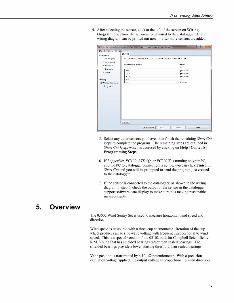
14. After selecting the sensor, click at the left of the screen on Wiring Diagram to see how the sensor is to be wired to the datalogger. The wiring diagram can be printed out now or after more sensors are added.
15. Select any other sensors you have, then finish the remaining Short Cut steps to complete the program. The remaining steps are outlined in Short Cut Help, which is accessed by clicking on Help | Contents | Programming Steps.
16. If LoggerNet, PC400, RTDAQ, or PC200W is running on your PC, and the PC to datalogger connection is active, you can click Finish in Short Cut and you will be prompted to send the program just created to the datalogger.
17. If the sensor is connected to the datalogger, as shown in the wiring diagram in step 6, check the output of the sensor in the datalogger support software data display to make sure it is making reasonable measurements.
5. Overview The 03002 Wind Sentry Set is used to measure horizontal wind speed and direction.
Wind speed is measured with a three cup anemometer. Rotation of the cup wheel produces an ac sine wave voltage with frequency proportional to wind speed. This is a special version of the 03102 built for Campbell Scientific by R.M. Young that has shielded bearings rather than sealed bearings. The shielded bearings provide a lower starting threshold than sealed bearings.
Vane position is transmitted by a 10-kΩ potentiometer. With a precision excitation voltage applied, the output voltage is proportional to wind direction.
7
R.M. Young Wind Sentry
The 03101 Anemometer and 03301 Vane can be ordered as separate sensors, which are also covered in this manual. These two sensors combined differ from the 03002 only by the absence of a junction box. The R.M. Young Instruction Manual includes additional information on the operating principles, installation, and maintenance of the sensor.
Cable length for the Wind Sentry is specified when the sensor is ordered. TABLE 5-1 gives the recommended lead length for mounting the sensor at the top of the tripod/tower with a CM200-series crossarm.
TABLE 5-1. Recommended Cable Lengths
CM106B CM110 CM115 CM120 UT10 UT20 UT30
12 ft 15 ft 20 ft 25 ft 15 ft 25 ft 38 ft
The 03002’s cable can terminate in:
• Pigtails that connect directly to a Campbell Scientific datalogger (option –PT).
• Connector that attaches to a prewired enclosure (option –PW). Refer to www.campbellsci.com/prewired-enclosures for more information.
• Connector that attaches to a CWS900 Wireless Sensor Interface (option –CWS). The CWS900 allows the 03002 to be used in a wireless sensor network. Refer to www.campbellsci.com/cws900 for more information.
6. Specifications Features:
• Designed for continuous, long term, unattended operation in adverse conditions
• Small size, simplicity, and rugged construction provide a quality instrument for a modest price
• Ideal for wind profile studies • Compatible with the LLAC4 4-channel Low Level AC Conversion
Module, which increases the number of anemometers one datalogger can measure
• Campbell Scientific version uses shielded bearings, which lowers the anemometer’s starting threshold
• Compatible with Campbell Scientific CRBasic dataloggers: CR6, CR200(X) series, CR800 series, CR1000, CR3000, CR5000, and CR9000X.
8
R.M. Young Wind Sentry
6.1 Wind Speed (Anemometer) Range: 0 to 50 m s–1 (112 mph), gust survival 60 m s–1 (134
mph) Sensor: 12 cm diameter cup wheel assembly, 40 mm
diameter hemispherical cups Accuracy: ±0.5 m s–1 (1.1 mph) Turning Factor: 75 cm (2.5 ft) Distance Constant (63% recovery): 2.3 m (7.5 ft) Threshold: 0.5 m s–1 (1.1 mph) Transducer: Stationary coil, 1300 ohm nominal resistance Output: AC sine wave signal induced by rotating magnet on
cup wheel shaft 100 mV peak-to-peak at 60 rpm; 6 V peak-to-peak
at 3600 rpm Output Frequency: 1 cycle per cup wheel revolution; 0.75 m s–1 per Hz Cup Wheel Diameter: 12 cm (4.7 in) Weight: 113 g (4 oz)
6.2 Wind Direction (Vane) Range: 360° mechanical, 352° electrical (8° open) Sensor: Balanced vane, 16 cm turning radius Accuracy: ±5° Damping Ratio: 0.2 Delay Distance (50% recovery): 0.5 m (1.6 ft) Threshold: 0.8 m s–1 (1.8 mph) at 10° displacement (1.8 m s–1 (4 mph) at 5° displacement) Transducer: Precision conductive plastic potentiometer;
10 kΩ resistance; 1.0% linearity; life expectancy 50 million revolutions
Rated 1 W at 40 °C, 0 W at 125 °C Transducer Excitation Requirement: Regulated dc voltage, 15 Vdc max Output: Analog dc voltage proportional to wind direction
angle with regulated excitation voltage supplied by the datalogger
Vane Length: 22 cm (8.7 in) Vane Weight: 170 g (6 oz)
6.3 Wind Sentry Assembly Operating Temperature: –50 to 50 °C assuming non-riming conditions Overall Height: 32 cm (12.6 in) Crossarm Length: 40 cm (15.7 in) between instruments (center-to-
center) Mounting Diameter: 34 mm (1.34 in), mounts on standard 1 in. IPS pipe
7. Installation If you are programming your datalogger with Short Cut, skip Section 7.3, Wiring, and Section 7.4, Programming. Short Cut does this work for you. See Section 4, Quickstart, for a Short Cut tutorial.
9
R.M. Young Wind Sentry
7.1 Siting Locate wind sensors away from obstructions (e.g., trees and buildings). As a general rule of thumb, there should be a horizontal distance of at least ten times the height of the obstruction between the wind set and the obstruction. If it is necessary to mount the sensors on the roof of a building, the height of the sensors above the roof, should be at least 1.5 times the height of the building. See Section 10, References, for a list of references that discuss siting wind speed and direction sensors.
7.2 Assembly and Mounting 7.2.1 03002 Wind Sentry Set
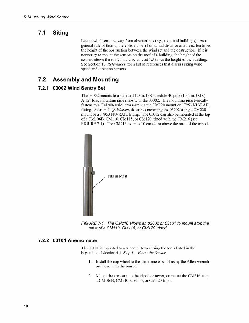
The 03002 mounts to a standard 1.0 in. IPS schedule 40 pipe (1.34 in. O.D.). A 12” long mounting pipe ships with the 03002. The mounting pipe typically fastens to a CM200-series crossarm via the CM220 mount or 17953 NU-RAIL fitting. Section 4, Quickstart, describes mounting the 03002 using a CM220 mount or a 17953 NU-RAIL fitting. The 03002 can also be mounted at the top of a CM106B, CM110, CM115, or CM120 tripod with the CM216 (see FIGURE 7-1). The CM216 extends 10 cm (4 in) above the mast of the tripod.
FIGURE 7-1. The CM216 allows an 03002 or 03101 to mount atop the mast of a CM110, CM115, or CM120 tripod
7.2.2 03101 Anemometer The 03101 is mounted to a tripod or tower using the tools listed in the beginning of Section 4.1, Step 1—Mount the Sensor.
1. Install the cup wheel to the anemometer shaft using the Allen wrench provided with the sensor.
2. Mount the crossarm to the tripod or tower, or mount the CM216 atop a CM106B, CM110, CM115, or CM120 tripod.
Fits in Mast
10
R.M. Young Wind Sentry
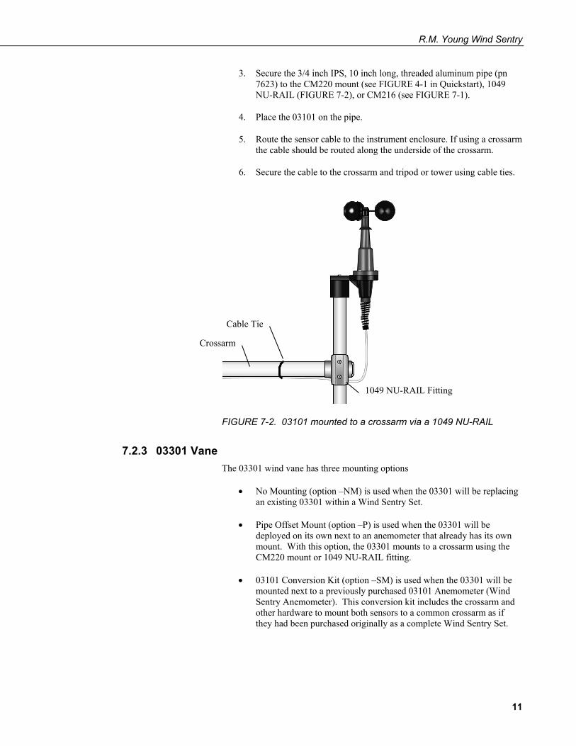
3. Secure the 3/4 inch IPS, 10 inch long, threaded aluminum pipe (pn 7623) to the CM220 mount (see FIGURE 4-1 in Quickstart), 1049 NU-RAIL (FIGURE 7-2), or CM216 (see FIGURE 7-1).
4. Place the 03101 on the pipe.
5. Route the sensor cable to the instrument enclosure. If using a crossarm the cable should be routed along the underside of the crossarm.
6. Secure the cable to the crossarm and tripod or tower using cable ties.
FIGURE 7-2. 03101 mounted to a crossarm via a 1049 NU-RAIL
7.2.3 03301 Vane The 03301 wind vane has three mounting options
• No Mounting (option –NM) is used when the 03301 will be replacing an existing 03301 within a Wind Sentry Set.
• Pipe Offset Mount (option –P) is used when the 03301 will be deployed on its own next to an anemometer that already has its own mount. With this option, the 03301 mounts to a crossarm using the CM220 mount or 1049 NU-RAIL fitting.
• 03101 Conversion Kit (option –SM) is used when the 03301 will be mounted next to a previously purchased 03101 Anemometer (Wind Sentry Anemometer). This conversion kit includes the crossarm and other hardware to mount both sensors to a common crossarm as if they had been purchased originally as a complete Wind Sentry Set.
Cable Tie
Crossarm
1049 NU-RAIL Fitting
11
R.M. Young Wind Sentry
7.3 Wiring Connections to CRBasic dataloggers are given in TABLE 7-1 and TABLE 7-2. To wire an Edlog datalogger, see an older manual at www.campbellsci.com/old-manuals, or contact a Campbell Scientific application engineer for assistance.
TABLE 7-1. 03002-L Wiring
Color
Description
CR6 CR800 CR5000 CR3000 CR1000
CR200(X)
Red Wind Spd. Signal Pulse P_LL
Black Wind Spd. Reference Clear Shield White Wind Dir. Reference Green Wind Dir. Signal SE Analog SE Analog
Blue Wind Dir. Excitation Excitation Excitation
TABLE 7-2. 03101 and 03301 Wiring
Color
Description
CR6 CR800 CR5000 CR3000 CR1000
CR200(X)
Black Wind Spd. Signal Pulse P_LL
White Wind Spd. Reference Clear Wind Spd. Shield
Red Wind Dir. Signal SE Analog SE Analog
Black Wind Dir. Excitation Excitation Excitation
White Wind Dir. Reference Clear Wind Dir. Shield
12

R.M. Young Wind Sentry
Wind Speed 03101 Wind Direction 03301
7.4 Programming Short Cut is the best source for up-to-date datalogger programming code. Programming code is needed,
• when creating a program for a new datalogger installation.
• when adding sensors to an existing datalogger program.
If your data acquisition requirements are simple and you are connecting the sensor to a pulse port, you can probably create and maintain a datalogger program exclusively with Short Cut. If your data acquisition needs are more complex, the files that Short Cut creates are a great source for programming code to start a new program or add to an existing custom program.
Short Cut cannot edit programs after they are imported and edited in CRBasic Editor.
A Short Cut tutorial is available in Section 4.2, Step 2 — Use SCWin to Program Datalogger and Generate Wiring Diagram. If you wish to import Short Cut code into CRBasic Editor to create or add to a customized program, follow the procedure in Appendix A.1, Importing Short Cut Code into a Program Editor. Programming basics for CRBasic dataloggers are provided in the following sections. Complete program examples for select CRBasic dataloggers can be found in Appendix B, Example Programs. Programming basics and programming examples for Edlog dataloggers are provided at www.campbellsci.com/old-manuals.
7.4.1 Wind Speed Wind speed is measured with the Pulse Count instruction (PulseCount() in CRBasic. Use the low level AC configuration.
The expression for wind speed (U) is:
U = MX + B
NOTE
13
R.M. Young Wind Sentry
where
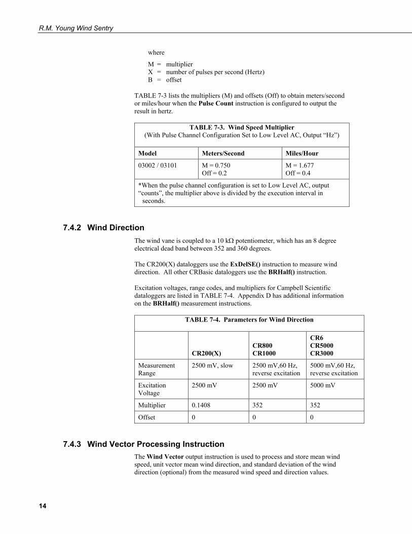
M = multiplier X = number of pulses per second (Hertz) B = offset
TABLE 7-3 lists the multipliers (M) and offsets (Off) to obtain meters/second or miles/hour when the Pulse Count instruction is configured to output the result in hertz.
TABLE 7-3. Wind Speed Multiplier (With Pulse Channel Configuration Set to Low Level AC, Output “Hz”)
Model Meters/Second Miles/Hour
03002 / 03101 M = 0.750 Off = 0.2
M = 1.677 Off = 0.4
*When the pulse channel configuration is set to Low Level AC, output “counts”, the multiplier above is divided by the execution interval in
seconds.
7.4.2 Wind Direction The wind vane is coupled to a 10 kΩ potentiometer, which has an 8 degree electrical dead band between 352 and 360 degrees.
The CR200(X) dataloggers use the ExDelSE() instruction to measure wind direction. All other CRBasic dataloggers use the BRHalf() instruction.
Excitation voltages, range codes, and multipliers for Campbell Scientific dataloggers are listed in TABLE 7-4. Appendix D has additional information on the BRHalf() measurement instructions.
TABLE 7-4. Parameters for Wind Direction
CR200(X)
CR800 CR1000
CR6 CR5000 CR3000
Measurement Range
2500 mV, slow 2500 mV,60 Hz, reverse excitation
5000 mV,60 Hz, reverse excitation
Excitation Voltage
2500 mV 2500 mV 5000 mV
Multiplier 0.1408 352 352
Offset 0 0 0
7.4.3 Wind Vector Processing Instruction The Wind Vector output instruction is used to process and store mean wind speed, unit vector mean wind direction, and standard deviation of the wind direction (optional) from the measured wind speed and direction values.
14
R.M. Young Wind Sentry
7.4.4 Long Lead Lengths When sensor lead length exceeds 100 feet, the settling time allowed for the measurement of the vane should be increased to 20 milliseconds.
For the CR200(X), increase the Settling Time parameter of the ExDelSE() instruction to 20 milliseconds (20,000 microseconds). For the other CRBasic dataloggers, increase the Settling Time parameter of the BRHalf() instruction to 20 milliseconds (20,000 microseconds).
The 60 Hz rejection option cannot be used with the Half Bridge instruction, when the delay is not zero. Do not use long lead lengths in electrically noisy environments.
8. Sensor Maintenance Every month do a visual/audio inspection of the anemometer at low wind speeds. Verify that the cup assembly and wind vane rotate freely. Inspect the sensor for physical damage.
Replace the anemometer bearings when they become noisy, or the wind speed threshold increases above an acceptable level. The condition of the bearings can be checked with a paper clip as described in the R.M. Young manual
The potentiometer has a life expectancy of fifty million revolutions. As it becomes worn, the element can produce noisy signals or become nonlinear. Replace the potentiometer when the noise or nonlinearity becomes unacceptable.
Refer to the Assistance page at the beginning of this document for the procedure of returning the sensor to Campbell Scientific for wind vane and bearing replacement.
9. Troubleshooting 9.1 Wind Direction
Symptom: NAN, –9999, or no change in direction
1. Check that the sensor is wired to the excitation and single-ended channel specified by the measurement instruction.
2. Verify that the excitation voltage and range code are correct for the datalogger type.
3. Disconnect the sensor from the datalogger and use an ohm meter to check the potentiometer. Resistance should be about 10 kΩ between the black and white wires. The resistance between either the black/red or white/red wires for the 03301 and blue/red or white/red for the 03002 should vary from 1 kΩ to 11 kΩ depending on vane position. Resistance when the vane is in the 8 degree dead band should be about 1 MΩ.
CAUTION
15

R.M. Young Wind Sentry
Symptom: Incorrect wind direction
1. Verify that the excitation voltage, range code, multiplier, and offset parameters are correct for the datalogger type.
2. Check orientation of sensor as described in Section 4.1, Step 1 — Mount the Sensor.
9.2 Wind Speed Symptom: No wind speed
1. Check that the sensor is wired to the pulse channel specified by the pulse count instruction.
2. Disconnect the sensor from the datalogger and use an ohm meter to check the coil. The resistance between the white and black wires for the 03101 and black and red wires for the 03002 should be a nominal 1300 ohms. Infinite resistance indicates an open coil; low resistance indicates a shorted coil.
3. Verify that the configuration code, and multiplier and offset parameters for the pulse count instruction are correct for the datalogger type.
10. References The following references give detailed information on siting wind speed and wind direction sensors.
EPA, 1989: Quality Assurance Handbook for Air Pollution Measurements System, Office of Research and Development, Research Triangle Park, NC, 27711.
EPA, 1987: On-Site Meteorological Program Guidance for Regulatory Modeling Applications, EPA-450/4-87-013, Office of Air Quality Planning and Standards, Research Triangle Park, NC 27711.
The State Climatologist, 1985: Publication of the American Association of State Climatologists: Height and Exposure Standards, for Sensors on Automated Weather Stations, vol. 9, No. 4.
WMO, 1983: Guide to Meteorological Instruments and Methods of Observation, World Meteorological Organization, No. 8, 5th edition, Geneva, Switzerland.
16

Appendix A. Importing Short Cut Code This tutorial shows:
• How to import a Short Cut program into a program editor for additional refinement.
• How to import a wiring diagram from Short Cut into the comments of a custom program.
A.1 Importing Short Cut Code into a Program Editor Short Cut creates files that can be imported into CRBasic Editor program editor. These files normally reside in the C:\campbellsci\SCWin folder and have the following extensions:
• .DEF (wiring and memory usage information) • .CR6 (CR6 datalogger code) • .CR2 (CR200(X) datalogger code) • .CR1 (CR1000 datalogger code) • .CR8 (CR800 datalogger code) • .CR3 (CR3000 datalogger code) • .CR9 (CR9000(X) datalogger code)
Use the following procedure to import Short Cut code into CRBasic Editor (CR6, CR200(X), CR1000, CR800, CR3000, CR5000 CR9000(X) dataloggers).
1. Create the Short Cut program following the procedure in Section 4, Quickstart. Finish the program and exit Short Cut. Make note of the file name used when saving the Short Cut program.
2. Open CRBasic Editor.
3. Click File | Open. Assuming the default paths were used when Short Cut was installed, navigate to C:\CampbellSci\SCWin folder. The file of interest has a “.CR6”, “.CR2”, “.CR1”, “.CR8”, “.CR3”, “.CR9”, or “.CR5” extension, for CR6, CR200(X), CR1000, CR800, CR3000, CR9000(X), or CR5000 dataloggers, respectively. Select the file and click Open.
4. Immediately save the file in a folder different from \Campbellsci\SCWin, or save the file with a different file name.
Once the file is edited with CRBasic Editor, Short Cut can no longer be used to edit the datalogger program. Change the name of the program file or move it, or Short Cut may overwrite it next time it is used.
5. The program can now be edited, saved, and sent to the datalogger.
6. Import wiring information to the program by opening the associated .DEF file. Copy and paste the section beginning with heading “-Wiring for
NOTE
A-1

Appendix A. Importing Short Cut Code
CRXXX–” into the CRBasic program, usually at the head of the file. After pasting, edit the information such that a ' character (single quotation mark) begins each line. This character instructs the datalogger compiler to ignore the line when compiling the datalogger code.
A-2

Appendix B. Example Programs This CR1000 program measures the 03002 every 5 seconds, and store mean wind speed, unit vector mean direction, and standard deviation of the direction every 60 minutes. Wiring for the examples is given in TABLE B-1.
TABLE B-1. Wiring for Example Programs using the 03002-L
Color Description CR1000
Red Wind Spd. Signal P1
Black Wind Spd. Reference Clear Wind Spd. Shield
Green Wind Dir. Signal SE 1
Blue Wind Dir. Excitation VX 1 or EX 1
White Wind Dir. Reference
'CR1000 'Declare Variables and Units Public Batt_Volt Public WS_ms Public WindDir Units Batt_Volt=Volts Units WS_ms=meters/second Units WindDir=Degrees 'Define Data Tables DataTable(Table1,True,-1) DataInterval(0,60,Min,10) WindVector (1,WS_ms,WindDir,FP2,False,0,0,0) FieldNames("WS_ms_S_WVT,WindDir_D1_WVT,WindDir_SD1_WVT") EndTable 'Main Program BeginProg Scan(5,Sec,1,0) 'Default Datalogger Battery Voltage measurement Batt_Volt: Battery(Batt_Volt) '03002 or 03101 RM Young Wind Sentry Wind Speed Sensor measurement - WS_ms: PulseCount(WS_ms,1,1,1,1,0.75,0.2) If WS_ms<0.21 Then WS_ms=0 '03002 or 03301 RM Young Wind Sentry Wind Direction Sensor measurement - WindDir: BrHalf(WindDir,1,mV2500,1,1,1,2500,True,0,_60Hz,352,0) 'Use mV5000 range and 5000 mV excitation for CR3000 and CR5000 dataloggers. If WindDir>=360 OR WindDir<0 Then WindDir=0 'Call Data Tables and Store Data CallTable(Table1) NextScan EndProg
B-1

Appendix B. Example Programs
B-2

Appendix C. Wind Direction Sensor Orientation C.1 Determining True North and Sensor Orientation
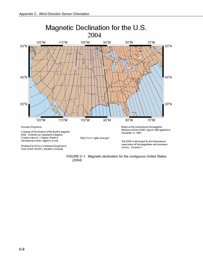
Orientation of the wind direction sensor is done after the datalogger has been programmed, and the location of True North has been determined. True North is usually found by reading a magnetic compass and applying the correction for magnetic declination; where magnetic declination is the number of degrees between True North and Magnetic North. The preferred method to obtain the magnetic declination for a specific site is to use a computer service offered by NOAA at www.ngdc.noaa.gov/geomag. Magnetic declination can also be obtained from a map or local airport. A general map showing magnetic declination for the contiguous United States is shown in FIGURE C-1.
Declination angles east of True North are considered negative, and are subtracted from 360 degrees to get True North as shown FIGURE C-2 (0° and 360° are the same point on a compass). Declination angles west of True North are considered positive, and are added to 0 degrees to get True North as shown in FIGURE C-3. For example, the declination for Logan, Utah is 14° East. True North is 360° – 14°, or 346° as read on a compass.
Orientation is most easily done with two people, one to aim and adjust the sensor, while the other observes the wind direction displayed by the datalogger.
1. Establish a reference point on the horizon for True North.
2. Sighting down the instrument center line, aim the nose cone, or counterweight at True North. Display the input location or variable for wind direction using a hand-held keyboard display, PC, or laptop.
3. Loosen the U-bolt on the CM220 or the set screws on the NU-RAIL that secure the base of the sensor to the crossarm. While holding the vane position, slowly rotate the sensor base until the datalogger indicates 0 degrees. Tighten the set screws.
C-1
Appendix C. Wind Direction Sensor Orientation
FIGURE C-1. Magnetic declination for the contiguous United States (2004)
C-2

Appendix C. Wind Direction Sensor Orientation
FIGURE C-2. Declination angles east of True North are subtracted from 0 to get True North
FIGURE C-3. Declination angles west of True North are added to 0 to get True North
C-3

Appendix C. Wind Direction Sensor Orientation
C-4
Appendix D. Wind Direction Measurement Theory
It is not necessary to understand the concepts in this section for the general operation of the 03002 with Campbell Scientific’s datalogger.
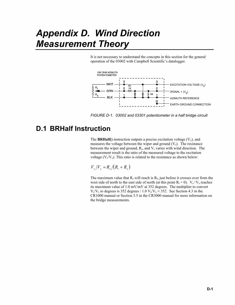
FIGURE D-1. 03002 and 03301 potentiometer in a half bridge circuit
D.1 BRHalf Instruction The BRHalf() instruction outputs a precise excitation voltage (Vx), and measures the voltage between the wiper and ground (Vs). The resistance between the wiper and ground, Rs, and Vs varies with wind direction. The measurement result is the ratio of the measured voltage to the excitation voltage (Vs/Vx). This ratio is related to the resistance as shown below:
( )stsxs RRRVV +=
The maximum value that Rs will reach is Rf, just before it crosses over from the west side of north to the east side of north (at this point Rt = 0). Vs / Vx reaches its maximum value of 1.0 mV/mV at 352 degrees. The multiplier to convert Vs/Vx to degrees is 352 degrees / 1.0 Vs/Vx = 352. See Section 4.3 in the CR1000 manual or Section 3.5 in the CR3000 manual for more information on the bridge measurements.
EXCITATION VOLTAGE (Vx)
SIGNAL + (Vs)
AZIMUTH REFERENCE
EARTH GROUND CONNECTION
Rt
Rs
D-1

Appendix D. Wind Direction Measurement Theory
D-2

METEOROLOGICAL INSTRUMENTS
INSTRUCTIONS
R.M. YOUNG COMPANY 2801 AERO PARK DRIVE, TRAVERSE CITY, MICHIGAN 49686, USATEL: (231) 946-3980 FAX: (231) 946-4772 WEB: www.youngusa.com
P/N: 03002-5-90 REV: D110210
WIND SENTRYMODEL 03002-5

Page 1
03002-5-90(D)
MODEL 03002-5WIND SENTRYINCLUDES MODELS 03102 & 03302
INTRODUCTIONThe Wind Sentry Anemometer and Vane measure horizontal wind speed and wind direction. The small size, simplicity, and corrosion resistant construction provide a professional quality instrument at a modest cost. The cup wheel and vane shafts use stainless steel precision instrument grade ball bearings which are lubricated with a wide temperature range high quality instrument oil. Standard bearings have light contacting seals to exclude contamination and help retain lubricant for longer service life.
Cup wheel rotation produces an AC sine wave voltage signal with frequency directly proportional to wind speed. This AC signal is induced in a stationary coil by a two pole ring magnet mounted on the cup wheel shaft. One complete sine wave cycle is produced for each cup wheel revolution.
Wind vane position is transmitted by a 10K ohm precision conductive plastic potentiometer which requires a regulated excitation voltage. With a constant voltage applied to the potentiometer, the output signal is an analog voltage directly proportional to wind direction angle.
The instrument mounts on standard 1 inch pipe, outside diameter 34mm (1.34") and is supplied with a crossarm and junction box for cable connections. Wind Sentry anemometers and windvanes are available separately with similar mounting and junction box.
INITIAL CHECK-OUTWhen the Wind Sentry is unpacked, check it carefully for any signs of shipping damage. Place the cup wheel on the anemometer shaft and secure it by tightening the set screw on the side of the hub. The instrument is aligned, balanced, and fully calibrated before shipment; however, it should be checked both mechanically and electrically before installation. The vane and cup wheel should easily rotate 360° without friction. Check vane balance by holding the instrument so the vane surface is horizontal. It should have near-neutral torque without any particular tendency to rotate. A slight imbalance will not degrade performance.
The wind direction potentiometer requires a stable DC excitation voltage. Do not exceed 15 volts. When the potentiometer wiper is in the 8° deadband region, the output signal is "floating" and may show varying or unpredictable values. To prevent false readings, signal conditioning electronics should clamp the signal to excitation or reference level when this occurs. Note: All YOUNG signal conditioning devices clamp the signal to excitation level. Avoid a short circuit between the wind direction signal line and either the excitation or ground reference lines. Although there is a current limiting resistor in series with the wiper for protection, damage to the potentiometer may occur if a short circuit condition exists.
Before installation, connect the instrument to a signal conditioning device as shown in the wiring diagram and check for proper wind speed and direction values. To check wind speed, temporarily remove the cup wheel and connect an Anemometer Drive to the cup wheel shaft. Details appear in the CALIBRATION section.
INSTALLATIONProper placement of the instrument is very important. Eddies from trees, buildings, or other structures can greatly influence wind speed and direction observations. To get meaningful data for most applications, locate the instrument well above or upwind of such obstructions. As a general rule, the air flow around a structure is disturbed to twice the height of the structure upwind, six times the height downwind, and twice the height of the structure above ground. For some observations it may not be practical or necessary to meet these guidelines.
WIND SPEED SPECIFICATION SUMMARY
Range 0 to 50 m/s (112 mph), gust survival 60 m/s (134 mph)
Sensor 12 cm diameter cup wheel assembly, 40 mm diameter hemispherical cupsTurning Factor 75 cm (2.46 ft)Distance Constant 2.3 m (7.5 ft) (63% recovery)Threshold 0.5 m/s (1.1 mph)Transducer Stationary coil, 1300 ohm nominal resistanceTransducer Output AC sine wave signal induced by rotating
magnet on cup wheel shaft 100 mV p-p at 60 rpm. 6V p-p at 3600 rpm.
Output Frequency 1 cycle per cup wheel revolution.
WIND DIRECTION (AZIMUTH) SPECIFICATION SUMMARY
Range 360° mechanical, 352° electrical (8° open)Sensor Balanced vane, 16 cm turning radius.Damping Ratio 0.2Delay Distance (50% recovery) 0.5 m (1.6 ft)Threshold 0.8 m/s (1.8 mph) at 10° displacementTransducer Precision conductive plastic potentiometer,
10K ohm ±20% resistance 1.0% linearity, life expectancy 50 million revolutions Rated 1 watt at 40°C, 0 watts at 125°C
Transducer Excitation Requirement Regulated DC voltage, 15 VDC max
Transducer Output Analog DC voltage proportional to wind direction angle with regulated excitation voltage applied across potentiometer
GENERAL
Operating Temperature -50 to 50°C (-58 to 122°F)
Page 2
03002-5-90(D)
FAILURE TO PROPERLY GROUND THE WIND SENTRY MAY RESULT IN ERRONEOUS SIGNALS
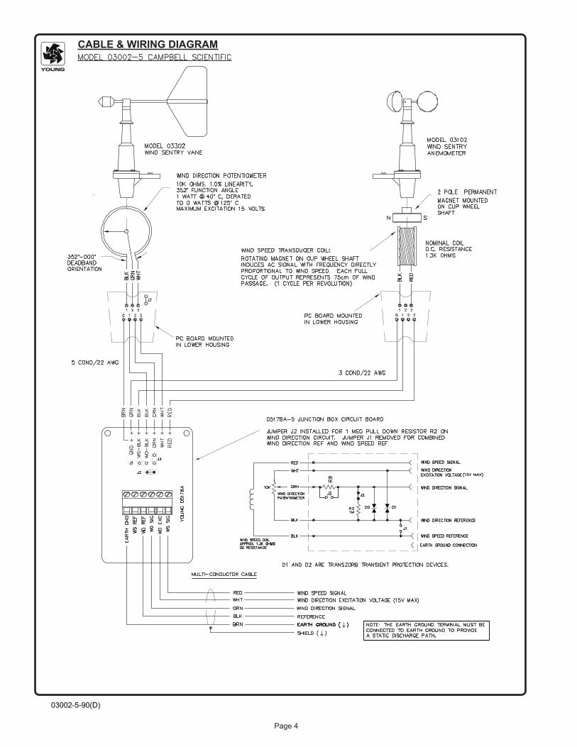
OR TRANSDUCER DAMAGE.
Grounding the Wind Sentry is vitally important. Without proper grounding, static electrical charge can build up during certain atmospheric conditions and discharge through the transducers. This discharge can cause erroneous signals or transducer failure. To direct the discharge away from the transducers, the instrument is made with a special anti-static plastic. It is very important that the instrument be connected to a good earth ground. There are two ways this may be accomplished. First, the Wind Sentry may be mounted on a metal pipe which is connected to earth ground. The mounting pipe should not be painted where the Wind Sentry is mounted. Towers or masts set in concrete should be connected to one or more grounding rods. If it is difficult to ground the mounting post in this manner, the following method should be used. Inside the junction box the terminal labeled EARTH GND is internally connected to the anti-static housings. This terminal should be connected to an earth ground (Refer to wiring diagram).
Initial installation is most easily done with two people; one to adjust the instrument position and the other to observe the indicating device. When anemometer and vane are mounted on the same cross arm (Model 03002), the azimuth potentiometer has been aligned at the factory such that the mounting cross arm should be oriented North-South with the vane on the North end.
To install the Wind Sentry, follow these steps:
1. MOUNT WIND SENTRY a) Connect sensor cable to Wind Sentry junction box. b) Place Wind Sentry on mounting post. Do Not tighten band clamp yet. c) Connect sensor cable to indicator.
2. ALIGN VANE a) Select a known azimuth reference point on the horizon. b) Sighting down vane centerline, point counterweight at reference point on horizon. c) While holding vane in position, slowly turn base until indicator displays proper value. d) Tighten mounting post band clamp.
CALIBRATIONThe Wind Sentry is fully calibrated before shipment and should require no adjustments. Recalibration may be necessary after some maintenance operations. Periodic calibration checks are desirable and may be necessary where the instrument is used in programs which require auditing of sensor performance.
For wind direction calibration, the following method can yield an accuracy of ±5° or better if carefully done. Begin by connecting the instrument to a signal conditioning circuit which indicates wind direction value. This may be an indicator which displays wind direction values in angular degrees or simply a voltmeter monitoring the output. Hold or mount the instrument so the vane center of rotation is over the center of a sheet of paper which has 30° or 45° crossmarkings. Position the instrument so the mounting crossarm is oriented north-south with the vane on the north and the anemometer on the south. With the counterweight pointing directly at the anemometer the wind direction signal should correspond to 180° or due south. Looking from above, visually align the vane with each of the crossmarkings and observe the indicator display. It should correspond to vane position within 5°. If not, it may be necessary to adjust the relative position of the vane skirt and shaft. See step 3 in the MAINTENANCE section under potentiometer replacement.
It is important to note that while the sensor mechanically rotates through 360°, the full scale wind direction signal from the signal
conditioning occurs at 352°. For example, in a circuit where 0 to 1.00 VDC represents 0° to 360°, the output must be adjusted for 0.978 VDC when the instrument is at 352° full scale. (352°/360° X 1.00 volts = 0.978 volts)
Wind speed calibration is determined by the cup wheel turning factor and the output characteristics of the transducer. Calibration formulas showing cup wheel rpm and frequency output vs. wind speed are included below.
To calibrate wind system electronics using an actual signal from the instrument, temporarily remove the cup wheel and connect an Anemometer Drive to the cup wheel shaft. Calculate wind speed by applying the appropriate calibration formula to the motor rpm and adjust the signal conditioning electronics for proper value. For example, with the cup wheel shaft turning at 1800 rpm, adjust the indicator to display 22.7 meters per second. ([(0.01250 X 1800) + 0.2] = 22.7)
CALIBRATION FORMULAS
Model 03102 Wind Sentry Anemometer
WIND SPEED vs CUP WHEEL RPM m/s = (0.01250 x rpm) + 0.2 knots = (0.02427 x rpm) + 0.4 mph = (0.02795 x rpm) + 0.4 km/hr = (0.04499 x rpm) + 0.7
WIND SPEED vs OUTPUT FREQUENCY - Hz m/s = (0.7500 x Hz) + 0.2 knots = (1.4562 x Hz) + 0.4 mph = (1.6770 x Hz) + 0.4 km/hr = (2.6994 x Hz) + 0.7
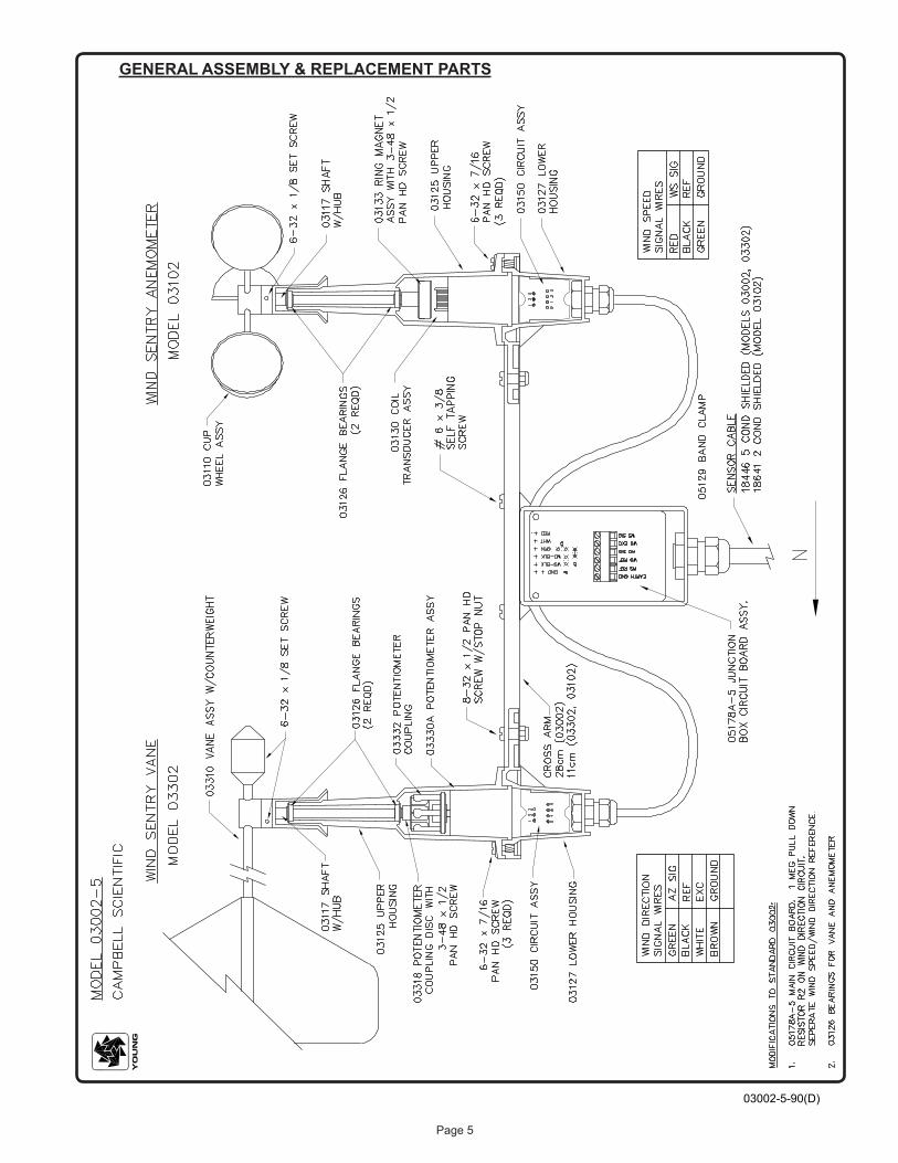
MAINTENANCEGiven proper care, the Wind Sentry should provide years of service. Because of its durable, corrosion resistant construction, the instrument requires little maintenance. The only components likely to require replacement due to normal wear are the precision ball bearings and the azimuth potentiometer. Replacement of these components should only be performed by a qualified instrument technician. If service facilities are not available, return the instrument to the factory. Refer to the accompanying drawings to become familiar with part names and locations. Maximum torque on all set screws is 80 oz-in.
POTENTIOMETER REPLACEMENT
The potentiometer has a life expectancy of fifty million revolutions. As it becomes worn, the element may produce noisy signals or become non-linear. When the signal noise or non-linearity become unacceptable, replace the potentiometer as follows:
1. REMOVE POTENTIOMETER a) Remove three screws which secure upper and lower
sections of main housing. b) Carefully remove upper housing exposing wiring connections
to circuit board. c) Unsolder potentiometer wires from circuit board.
Note color coding. d) Using a knife blade or similar instrument, loosen
potentiometer assembly from upper housing and slide it out. 2. INSTALL NEW POTENTIOMETER a) Slide new potentiometer cell into upper housing. Be sure to
engage cell key into housing notch. b) Solder potentiometer wires to circuit board.
Observe color code. c) Join two sections of main housing. Secure with screws
removed in step 1a.

Page 3
03002-5-90(D)
3. ALIGN VANE a) Connect excitation voltage and signal conditioning electronics to instrument according to wiring diagram. b) Loosen set screw in side of vane hub. c) Position instrument so crossarm is oriented north-south
with vane on north side. Orient vane to a known angular reference. (See CALIBRATION section.)
d) While holding vane in reference position, slowly turn vane skirt until signal conditioning system indicates proper value.
e) Tighten set screw on side of vane hub. Do not exceed 80 oz-in torque.
ANEMOMETER FLANGE BEARING REPLACEMENT
If anemometer bearings become noisy or wind speed threshold increases above an acceptable level, replace the bearings. Check bearing condition by hanging an ordinary paper clip (0.5 gm) on the outside edge of one cup while the instrument is held in a horizontal position. The cup should rotate downward. Failure to rotate due to the weight of the paper clip indicates anemometer bearings need replacement. Repeat this test at different positions to check full bearing rotation. Replace bearings as follows:
1. REMOVE BEARINGS a) Loosen set screw on side of cup wheel hub. Remove cup
wheel. b) Remove three screws which hold two sections of main housing. c) Carefully separate upper and lower housing. Remove
coil transducer assembly from upper housing. Do not disconnect from circuit board.
d) Loosen screw and remove ring magnet on end of shaft inside upper housing.
e) Slide shaft and skirt assembly out of both upper and lower bearings.
f) Using knife blade under bearing flange, carefully remove upper bearing.
g) Using a pencil, gently push out lower bearing from above.
2. INSTALL NEW BEARINGS a) Insert new upper bearing. Use care not to apply excessive
pressure. b) Slide cup wheel shaft through upper bearing. c) Slide lower bearing on shaft inside upper housing. d) Using ring magnet assembly, push lower bearing into its seat in upper housing. e) Secure ring magnet to shaft using screw removed in
step 1d. Use a small amount of sealant on screw to prevent it from loosening.
f) Join two housing sections. Secure using three screws removed in step 1b.
g) Place cup wheel on shaft. Tighten set screw on side of hub. Do not exceed 80 oz-in torque.
VANE FLANGE BEARING REPLACEMENT
If vane bearings become noisy or if wind direction threshold increases above an acceptable level, replace the bearings. Check bearing condition by adding two ordinary paper clips (0.5 gm each) to the back edge of the vane fin while the instrument and vane are held in a horizontal position. Gently release the vane. It should rotate downward. Failure to do so indicates the bearings need replacement. Repeat this test at various positions to check full bearing rotation.Since this procedure is similar to anemometer bearing replacement, only the major steps are shown here:
1. REMOVE BEARINGS (Remove coupling disc - same as ring magnet)2. INSTALL NEW BEARINGS3. ALIGN VANE (See CALIBRATION section)
WARRANTYThis product is warranted to be free of defects in materials and construction for a period of 12 months from date of initial purchase. Liability is limited to repair or replacement of defective item. A copy of the warranty policy may be obtained from R. M. Young Company.
CE COMPLIANCEThis product has been tested and shown to comply with European CE requirements for the EMC Directive. Please note that shielded cable must be used.
Declaration of Conformity
R. M. Young Company2801 Aero Park DriveTraverse City, MI 49686 USA
Models 03002, 03102, 03302
The undersigned hereby declares on behalf of R. M.Young Company that the above-referenced product, towhich this declaration relates, is in conformity with theprovisions of:
Council Directive 2004/108/EC (December 15, 2004)on Electromagnetic Compatibility
David PoinsettR&D Manager
Page 4
03002-5-90(D)
CABLE & WIRING DIAGRAM
Page 5
03002-5-90(D)
GENERAL ASSEMBLY & REPLACEMENT PARTS


Campbell Scientific Companies
Campbell Scientific, Inc. (CSI) 815 West 1800 North Logan, Utah 84321 UNITED STATES
www.campbellsci.com • [email protected]
Campbell Scientific Africa Pty. Ltd. (CSAf) PO Box 2450
Somerset West 7129 SOUTH AFRICA
www.csafrica.co.za • [email protected]
Campbell Scientific Australia Pty. Ltd. (CSA) PO Box 8108
Garbutt Post Shop QLD 4814 AUSTRALIA
www.campbellsci.com.au • [email protected]
Campbell Scientific (Beijing) Co., Ltd. 8B16, Floor 8 Tower B, Hanwei Plaza
7 Guanghua Road Chaoyang, Beijing 100004
P.R. CHINA www.campbellsci.com • [email protected]
Campbell Scientific do Brasil Ltda. (CSB) Rua Apinagés, nbr. 2018 Perdizes CEP: 01258-00 São Paulo SP
BRASIL www.campbellsci.com.br • [email protected]
Campbell Scientific Canada Corp. (CSC) 14532 – 131 Avenue NW Edmonton AB T5L 4X4
CANADA www.campbellsci.ca • [email protected]
Campbell Scientific Centro Caribe S.A. (CSCC) 300 N Cementerio, Edificio Breller
Santo Domingo, Heredia 40305 COSTA RICA
www.campbellsci.cc • [email protected]
Campbell Scientific Ltd. (CSL) Campbell Park
80 Hathern Road Shepshed, Loughborough LE12 9GX
UNITED KINGDOM www.campbellsci.co.uk • [email protected]
Campbell Scientific Ltd. (CSL France) 3 Avenue de la Division Leclerc
92160 ANTONY FRANCE
www.campbellsci.fr • [email protected]
Campbell Scientific Ltd. (CSL Germany) Fahrenheitstraße 13
28359 Bremen GERMANY
www.campbellsci.de • [email protected]
Campbell Scientific Spain, S. L. (CSL Spain) Avda. Pompeu Fabra 7-9, local 1
08024 Barcelona SPAIN
www.campbellsci.es • [email protected]
Please visit www.campbellsci.com to obtain contact information for your local US or international representative.