03 tt2550eu01al 01 frame signaling
DESCRIPTION
01 Frame SignalingTRANSCRIPT

2 Mbit/s Frame and Signaling Pulse Frame Siemens
TT2550EU01AL_011
Contents
1 Structure of the 3 Mbit/s Frame According to CCITT RecommendationG.704 3
2 Structure of the Signaling Pulse Frame According to CCITTRecommendation G.704 6
3 CRC4-Synchronization for Primary Multiplexer 9
4 Alarms 13
4.1 AIS Alarm Indication Signal 14
5 PCM Transmission Systems 16
6 Connecting Options of the Primary Multiplexer PCM30 19
7 Interfaces of PCM30H 21
8 Exercise 23
2 Mbit/s Frame and Signaling PulseFrame

Siemens 2 Mbit/s Frame and Signaling Pulse Frame
TT2550EU01AL_012

2 Mbit/s Frame and Signaling Pulse Frame Siemens
TT2550EU01AL_013
1 Structure of the 3 Mbit/s Frame Accordingto CCITT Recommendation G.704
Siemens 2 Mbit/s Frame and Signaling Pulse Frame
TT2550EU01AL_014
2-Mbit/s-Pulse frame
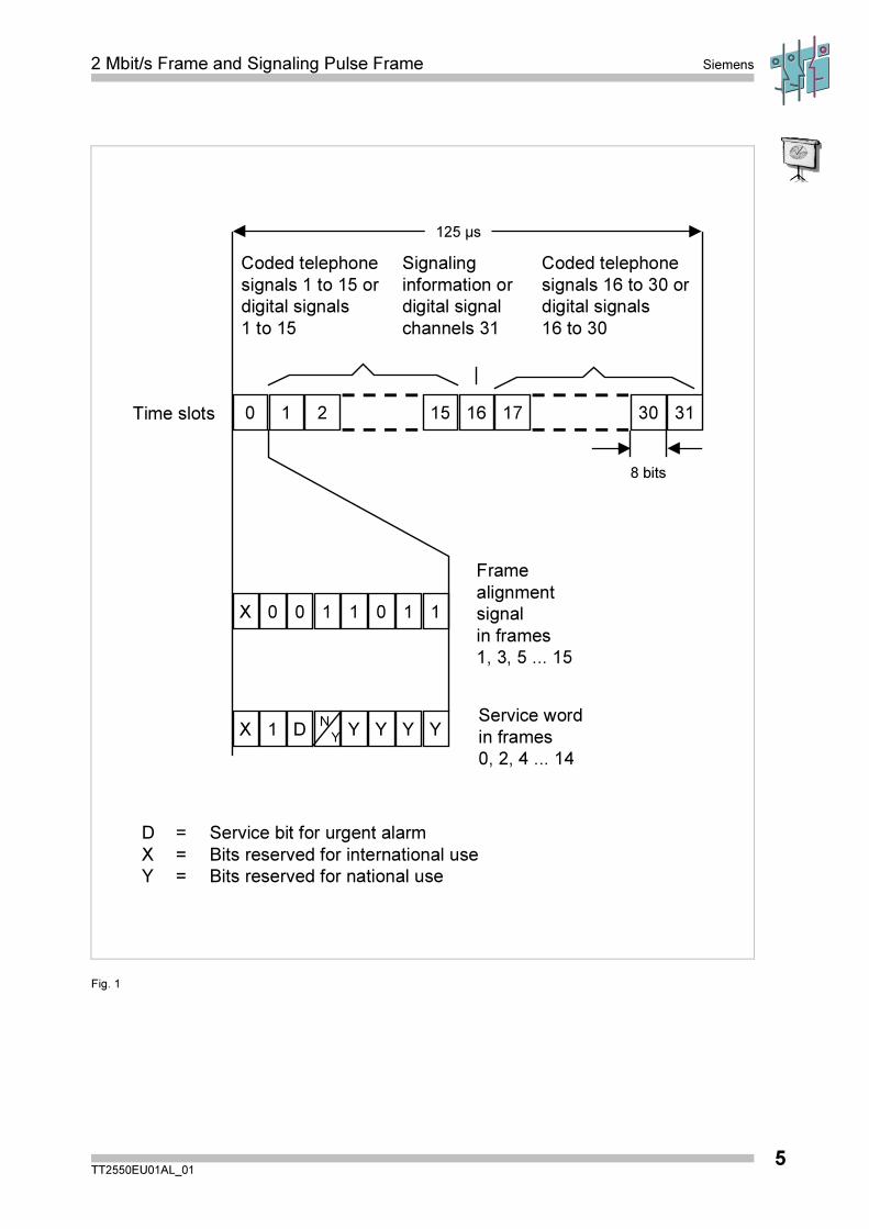
In the direction of transmission the primary multiplexer PCM30 transforms up to 30signals with different features into 64-kbit/s-digital signals and then combines them bythe time division multiplexing procedure to a 2048-kbit/s (2-Mbit/s)-signal, as shownin the pulse frame of fig. 1. The individual signals can be either LF-speech signalsconverted by pulse code modulation, or digital signals (e.g. data). In the receivedirection a demultiplexer isolates the individual signals out of the 2 Mbit/s signal. The64-kbit/s-digital signals are then converted again into analog signals.
The 2-Mbit/s pulse frame accord. to CCITT-recommendation G.704 consists of 32time intervals with 8 bits each (octets). In the intervals 1 to 15 and 17 to 31 speech ordigital signals are transmitted. Interval 16 contains the channel-associated signalinginformation (CAS) combined in one multiframe or, optionally, an additional device-specific data channel. In the interval 0 there is an alternate transmission of a framealignment signal (FAS) or a service word (SVW).
In order to isolate the individual signals out of the pulse frame the FAS is searchedfor in the received 2-Mbit/s-signal. As soon as the bit pattern is recognized, thedemultiplexer part of the central multiplexer synchronizes itself to time interval 0. Toadditionally ensure the synchronization the CRC4-procedure, which will be describedin the following, is applied. The service word is used for the transmission of urgentand non-urgent alarms (bit A and bit Sa4), for loop commands (bits Sa6 and Sa7)(CCITT-Redbook: bits D, N and Y1 to Y3).
2 Mbit/s Frame and Signaling Pulse Frame Siemens
TT2550EU01AL_015
Time slots
Coded telephone
signals 1 to 15 or
digital signals
1 to 15
Signaling
information or
digital signal
channels 31
Coded telephone
signals 16 to 30 or
digital signals
16 to 30
125 µs
8 bits
0 1 2 15 16 17 30 31
N
Y
X 0 0
1
1 0 1 1
Frame
alignment
signal
in frames
1, 3, 5 ... 15
X D Y Y Y YService word
in frames
0, 2, 4 ... 14
D = Service bit for urgent alarm
X = Bits reserved for international use
Y = Bits reserved for national use
1
Fig. 1
Siemens 2 Mbit/s Frame and Signaling Pulse Frame
TT2550EU01AL_016
2 Structure of the Signaling Pulse FrameAccording to CCITT RecommendationG.704
Signaling pulse frame
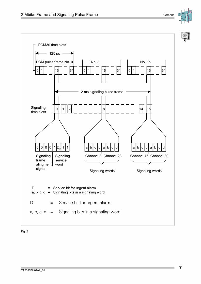
If analog signal insets are used the PCM30 transmits up to 30 speech signals in thetime intervals 1 to 15 and 17 to 31 of the 2-Mbit/s-pulse frame. It has to be ensuredthat the 64-kbit/s-signals in the time intervals 17 to 31 are counted as channels 16 to30. The individual channel-associated signaling information is coded with 4 bits (a, b,c, d) separate from the speech signal. The signaling of 30 channels can therefore becombined in 15 octets, which are supplemented by a code and service word of 8 bits,to a multiframe (signaling pulse frame). This multiframe is transmitted in time interval16 by 16 consecutive 2-Mbit/s-pulse frames (R0 to R15). The code and service wordcontained in interval R0 is necessary for the multiframe synchronization and for alarmmessages.
2 Mbit/s Frame and Signaling Pulse Frame Siemens
TT2550EU01AL_017
125 µs
0
DK
1 16 31 0 1 16 31 0 1 16 31
No. 8 No. 15PCM pulse frame No. 0
PCM30 time slots
2 ms signaling pulse frame
Signaling
time slots0 1 2 8 1514
0 0 0 0 1 1 1 ba b c d a dcba b c d a dc
Signaling
frame
alingment
signal
Signaling
service
word
Channel 8 Channel 23 Channel 15 Channel 30
Signaling words Signaling words
D = Service bit for urgent alarm
a, b, c, d = Signaling bits in a signaling word
D = Service bit for urgent alarm
a, b, c, d = Signaling bits in a signaling word
Fig. 2

Siemens 2 Mbit/s Frame and Signaling Pulse Frame
TT2550EU01AL_018
2 Mbit/s Frame and Signaling Pulse Frame Siemens
TT2550EU01AL_019
3 CRC4-Synchronization for PrimaryMultiplexer
Siemens 2 Mbit/s Frame and Signaling Pulse Frame
TT2550EU01AL_0110
With the data transmission of synchronous 64 kbit/s digital signals it is possible thatthe bit patterns of the FAS and the SVW are transmitted (either randomly or onpurpose) in the time intervals defined for user signals. If there is a synchronization ofthe receive side demultiplexer to this bit pattern, an isolation of the individual signalsis impossible. Therefore, the CRC4-procedure (Cyclic Redundancy Check by 4 bits)described in CCITT-recommendation G.704 is used in addition, to ensure thesynchronization.
For this, 16 consecutive 2-Mbit/s frames are combined to a CRC4 multiframeconsisting of 2 data blocks and of the multiframe parts I and II. The highest rating bitsof the service words in the first twelve 2-Mbit/s frames form the multiframe code word('001011'). Here, the synchronization is based on two criteria: finding the FAS of the2-Mbit/s frame and the FAS of a CRC4 multiframe.
To continually supervise the synchronization, a data block (e.g. block I) is modified ina data transmitter accord. to a certain algorithm, whereby a rest of 4 bits (the controlbits C1 and C4) is left over. These bits are transmitted as highest rating bits in the 2-Mbit frame alignment words of the following data block (block II). The data receiverprocesses the incoming data block according to the same algorithm as thetransmitter. Again, a rest of 4 bits is left over, which are compared individually to thecontrol bits received in the next data block (block II). In case of a correspondence,block I is considered to be error-free.
If 915 or more out of 1000 checked blocks were found to be faulty, a newsynchronization is started. A CRC4-error is indicated by two E-bits (CCITT-Redbook:Si-bits) at the transmit side; these two E-bits are transmitted as highest rating bits ofthe service words in the 2-Mbit/s frames 13 and 15 of the CRC4 multiframe. The BERof the 2-Mbit/s-signal can be derived from the number of faulty blocks. Thus, forexample, a number of 512 or more faulty blocks within a measuring interval of 1 sresults in a BER > 10-3.
2 Mbit/s Frame and Signaling Pulse Frame Siemens
TT2550EU01AL_0111
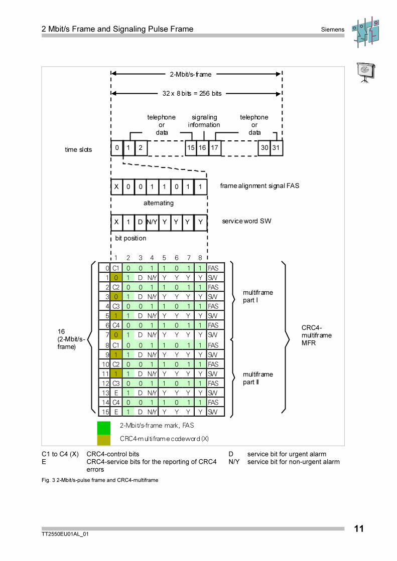
2-Mbit/s-frame
time slots
32 x 8 bits = 256 bits
telephoneor
data
signalinginformation
telephoneor
data
frame alignment signal FAS
service word SW
alternating
bit position
1 2 3 4 5 6 7 8
0 C1 0 0 1 1 0 1 1 FAS
1 0 1 D N/Y Y Y Y Y SW
2 C2 0 0 1 1 0 1 1 FAS
3 0 1 D N/Y Y Y Y Y SW
4 C3 0 0 1 1 0 1 1 FAS
5 1 1 D N/Y Y Y Y Y SW
6 C4 0 0 1 1 0 1 1 FAS
7 0 1 D N/Y Y Y Y Y SW
8 C1 0 0 1 1 0 1 1 FAS
9 1 1 D N/Y Y Y Y Y SW
10 C2 0 0 1 1 0 1 1 FAS
11 1 1 D N/Y Y Y Y Y SW
12 C3 0 0 1 1 0 1 1 FAS
13 E 1 D N/Y Y Y Y Y SW
14 C4 0 0 1 1 0 1 1 FAS
15 E 1 D N/Y Y Y Y Y SW
16(2-Mbit/s-frame)
multiframepart I
multiframepart II
CRC4-multiframeMFR
X 1 D N/Y Y Y Y Y
X 0 0 1 1 0 1 1
10 2 1615 17 3130
2-Mbit/s-frame mark, FAS
CRC4-multiframe codeword (X)
C1 to C4 (X) CRC4-control bits D service bit for urgent alarmE CRC4-service bits for the reporting of CRC4
errorsN/Y service bit for non-urgent alarm
Fig. 3 2-Mbit/s-pulse frame and CRC4-multiframe
2 Mbit/s Frame and Signaling Pulse Frame Siemens
TT2550EU01AL_0113
4 Alarms

Siemens 2 Mbit/s Frame and Signaling Pulse Frame
TT2550EU01AL_0114
4.1 AIS Alarm Indication Signal
D-Bit Service bit
AIS: Alarm indication signal
The AIS is an all-one-signal which, if an error occurs, is inserted as"replacement signal" only in forward direction.
� If a low bit rate signal (64 kbit/s) is lacking at the input, the AIS is inserted in thecorresponding time slot of the highest bit rate signal (2 Mbit/s), i.e. all other timeslots of the higher bit rate signal remain unaffected.
� If a faulty signal is received at the higher bit rate interface (2 Mbit/s), the AIS isinserted into all lower bit rate signals (64 kbit/s). A blocking signal evaluated by theoperator is inserted into telephone channels.
The higher bit rate signal is considered to be faulty if there is no signal available,the synchronizing word is not recognized (synchr. with the FAS or optionally withCRC4), or if the BER > 10-3.
In this case the D-bit is transmitted at the 2-Mbit/s output as feedback for thedistant end station (frame (SVW) TS0, bit 3).
� AIS can also be inserted if a device internal fault arises, such as an error in thetransmission clock. The error is determined device-specifically.
� If at the higher bit rate interface (2 Mbit/s) a signal with BER > 10-5/-6 is received,the N-bit can be transmitted optionally (i.e. device-specifically) at the 2 Mbit/soutput as feedback for the distant end station (frame (SVW) TS0, bit 4). In thiscase, no AIS is inserted.
� If the higher bit rate interface receives an AIS, this is through-connected to thelower bit rate signals (64 kbit/s) and the D-bit transmitted in backward direction.
� If the signaling multiplexer is out of order, it is possible to insert the AIS in time slot16 (multiframe AIS).
� If a multiframe AIS is received, the DK-bit is transmitted in backward direction.
� If the multiframe signaling word (TS0) (=TS16 of the frame) is not recognized, thespeech signals are blocked and the DK-bit transmitted in backward direction(multiframe TS0, bit 6).
� In case of a seizure acknowledgment alarm, the NK-bit is transmitted in backwarddirection (multiframe TS0, bit 7). This alarm occurs if the exchange receives noappropriate acknowledgment after a telephone channel has been seized.

2 Mbit/s Frame and Signaling Pulse Frame Siemens
TT2550EU01AL_0115
AIS Alarm Indication Signal
D-Bit Service bit D
Transmission of AIS and bit D
!!!
error
low bit rate
64 kbit/s
interface
higher bit rate
2 Mbit/s
interface
data signals:AIS
telephone blocked
channels
D-bit DK-bit
!!!
errorprimary multiplexer PCM 30
Fig. 5

Siemens 2 Mbit/s Frame and Signaling Pulse Frame
TT2550EU01AL_0115
5 PCM Transmission Systems
The transmission systems recommended by the CCITT and described below are thePCM30 system, with 2048 kbit/s (CCITT Recommendation G.732), and the PCM24system, with 1544 kbit/s (CCITT Recommendations G.733); these combine 30 and24 telephone channels per transmission direction respectively to form a time-divisionmultiplex signal. PCM30 transmission systems are used throughout Europe and inmay non-European countries; PCM24 transmission systems have been installedmainly in the USA, Canada and Japan. PCM30 and PCM24 are also known as"primary transmission systems" or basic systems. Their most important features aregiven in fig. 6.

2 Mbit/s Frame and Signaling Pulse Frame Siemens
TT2550EU01AL_0117
� Common characteristics PCM30 and PCM24
a Sampling frequency 8 kHz
b No. of samples per telephonesignal
8.000/s
c Pulse frame period 1 1
8 000125
b ss� � �
. /
d No. of bits in a PCM word 8 bits
e Bit rate of a telephone channel b.d = 8.000/s 8 bits = 64 kbit/s
� System-specific characteristics PCM30 PCM24
f Encoding/DecodingNo. of segments incharacteristic
A-law13
µ-law15
g Number of channel time slots perpulse frame
32 24
h Number of bits per pulse frame(* = additional bit)
d.g = 8 bits32 = 256 bits
d.g + 1* = 8 bits.24 + 1* = 193 bits
i Period of an 8-bit channel timeslot
c d
h
s. .�
��
125 8
256
aprox. 3.9 µs
c d
h
s. .�
��
125 8
193
aprox. 5.2 µs
k Bit rate of time division multiplexsignal
b.h =8.000/s. 256 bits =2.048 kbit/s
b.h. =8.000/s. 193 bits =1.544 kbit/s
Fig. 6 Characteristics of the PCM30 and PCM24 Transmission Systems

Siemens 2 Mbit/s Frame and Signaling Pulse Frame
TT2550EU01AL_0118
2 Mbit/s Frame and Signaling Pulse Frame Siemens
TT2550EU01AL_0119
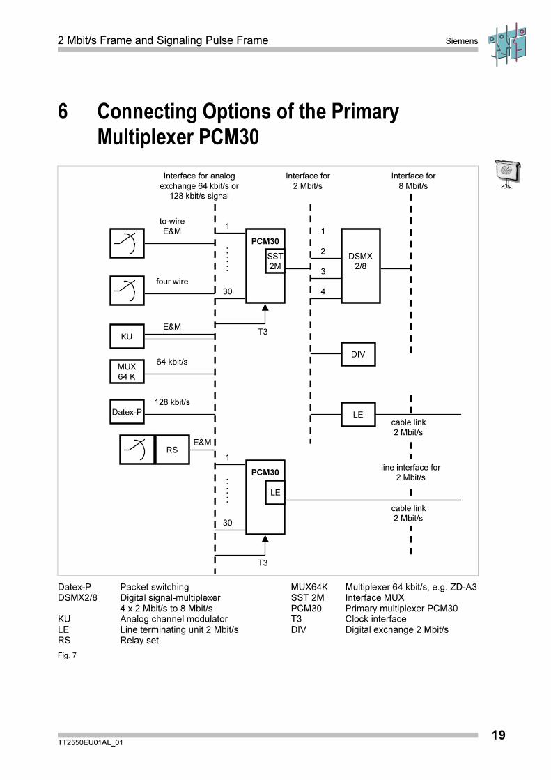
6 Connecting Options of the PrimaryMultiplexer PCM30
Interface for analog
exchange 64 kbit/s or
128 kbit/s signal
Interface for
2 Mbit/s
Interface for
8 Mbit/s
Datex-P
MUX
64 K
to-wire
E&M
four wire
KU
E&M
RS
128 kbit/s
64 kbit/s
E&M
1
PCM30
30
.
.
.
.
.
.
SST
2M
T3
1
PCM30
30
.
.
.
.
.
.LE
T3
1
DSMX
2/8
4
2
3
DIV
LE
line interface for
2 Mbit/s
cable link
2 Mbit/s
cable link
2 Mbit/s
Datex-P Packet switching MUX64K Multiplexer 64 kbit/s, e.g. ZD-A3DSMX2/8 Digital signal-multiplexer SST 2M Interface MUX
4 x 2 Mbit/s to 8 Mbit/s PCM30 Primary multiplexer PCM30KU Analog channel modulator T3 Clock interfaceLE Line terminating unit 2 Mbit/s DIV Digital exchange 2 Mbit/sRS Relay set
Fig. 7

Siemens 2 Mbit/s Frame and Signaling Pulse Frame
TT2550EU01AL_0120
2 Mbit/s Frame and Signaling Pulse Frame Siemens
TT2550EU01AL_0121
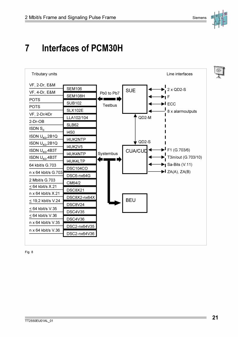
7 Interfaces of PCM30H
VF, 2-Dr, E&M
Tributary units Line interfaces
Pb0 to Pb7
Testbus
VF, 4-Dr, E&MSEM106
SEM108H
SUB102
SLX102E
LLA102/104
SLB62
I4S0
I4UK2NTP
I4UK2V5
I4UK4NTP
I4UK4LTP
DSC104CO
DSC6-nx64G
CM64/2
DSC8X21
DSC8X2-nx64X
2 x QD2-S
DSC8V24
DSC4V35
DSC4V36
DSC2-nx64V35
DSC2-nx64V36
POTS
POTS
VF, 2-Dr/4Dr
2-Dr-OB
ISDN S0
ISDN UK0
,2B1Q
ISDN UK0
,2B1Q
ISDN UK0
,4B3T
ISDN UK0
,4B3T
64 kbit/s G.703
n x 64 kbit/s G.703
2 Mbit/s G.703
< 19,2 kbit/s V.24
< 64 kbit/s V.35
< 64 kbit/s V.36
n x 64 kbit/s V.35
n x 64 kbit/s V.36
n x 64 kbit/s X.21
< 64 kbit/s X.21
SUE
QD2-M
F
ECC
8 x alarmoutputs
SystembusF1 (G.703/6)CUA/CUD
T3in/out (G.703/10)
Sa-Bits (V.11)
ZA(A), ZA(B)
QD2-S
BEU
Fig. 8

Siemens 2 Mbit/s Frame and Signaling Pulse Frame
TT2550EU01AL_0122
2 Mbit/s Frame and Signaling Pulse Frame Siemens
TT2550EU01AL_0123
8 Exercise
1. How many time slots does a frame consist of?
2. In which time slot is the voice channel 14 transmitted?
In which time slot is the data channel 25 transmitted?
3. What does the time slot 16 serve e for?
4. What does the time slot 0 serve for?
5. What does the D-bit serve for?
6. How many bits does the synchronization word contain and in which time slots is ittransmitted?
7. What is the duration for the transmission of one multi-frame?
8. What is the duration of one frame?
9. How many multi-frames are transmitted per second?
10. In which part of the multi-frame are the signaling bits of voice channel 22transmitted?
11. What does CRC4 mean?
12. What is the CRC4 code used for?
13. Is it possible to synchronize a primary multiplexer without CRC4 code?

Siemens 2 Mbit/s Frame and Signaling Pulse Frame
TT2550EU01AL_0124