03 g35 parking brake system
TRANSCRIPT
7/25/2019 03 G35 Parking Brake System
http://slidepdf.com/reader/full/03-g35-parking-brake-system 1/10PB-1
PARKING BRAKE SYSTEM
F BRAKES
CONTENTS
C
D
E
G
H
I
J
K
L
M
SECTION
A
B
PB
Revision; 2004 April 2003 G35 Sedan
PARKING BRAKE SYSTEM
PRECAUTIONS .......................................................... 2Precautions for Supplemental Restraint System
(SRS) “AIR BAG” and “SEAT BELT PRE-TEN-SIONER” .................................................................. 2
PARKING BRAKE SYSTEM ...................................... 3On-Vehicle Service (Foot Lever Type) ..................... 3
INSPECTION ........................................................ 3ADJUSTMENT ...................................................... 3
On-Vehicle Service (Hand Lever Type) .................... 4INSPECTION ........................................................ 4ADJUSTMENT ...................................................... 4
PARKING BRAKE CONTROL ................................... 5Components ............................................................. 5Removal and Installation .......................................... 6
REMOVAL ............................................................. 6INSTALLATION ..................................................... 6
Inspection ................................................................. 6PARKING BRAKE SHOE ........................................... 7
Components ............................................................. 7Removal and Installation .......................................... 7
REMOVAL ............................................................. 7INSPECTION AFTER REMOVAL ......................... 8INSTALLATION ..................................................... 8BREAKING IN DRUM AND LINING ...................... 9
SERVICE DATA AND SPECIFICATIONS (SDS) ...... 10Parking Drum Brake ............................................... 10Parking Brake Control ............................................ 10
7/25/2019 03 G35 Parking Brake System
http://slidepdf.com/reader/full/03-g35-parking-brake-system 2/10PB-2
PRECAUTIONS
Revision; 2004 April 2003 G35 Sedan
PRECAUTIONS PFP:00001
Precautions for Supplemental Restraint System (SRS) “AIR BAG” and “SEATBELT PRE-TENSIONER” AFS0021T
The Supplemental Restraint System such as “AIR BAG” and “SEAT BELT PRE-TENSIONER”, used alongwith a front seat belt, helps to reduce the risk or severity of injury to the driver and front passenger for certaintypes of collision. This system includes seat belt switch inputs and dual stage front air bag modules. The SRS
system uses the seat belt switches to determine the front air bag deployment, and may only deploy one frontair bag, depending on the severity of a collision and whether the front occupants are belted or unbelted.Information necessary to service the system safely is included in the SRS and SB section of this Service Man-ual.
WARNING: To avoid rendering the SRS inoperative, which could increase the risk of personal injury or death
in the event of a collision which would result in air bag inflation, all maintenance must be per-formed by an authorized NISSAN/INFINITI dealer.
Improper maintenance, including incorrect removal and installation of the SRS, can lead to per-sonal injury caused by unintentional activation of the system. For removal of Spiral Cable and AirBag Module, see the SRS section.
Do not use electrical test equipment on any circuit related to the SRS unless instructed to in this
Service Manual. SRS wiring harnesses can be identified by yellow and/or orange harnesses orharness connectors.
7/25/2019 03 G35 Parking Brake System
http://slidepdf.com/reader/full/03-g35-parking-brake-system 3/10
PARKING BRAKE SYSTEM
PB-3
C
D
E
G
H
I
J
K
L
M
A
B
PB
Revision; 2004 April 2003 G35 Sedan
PARKING BRAKE SYSTEM PFP:36010
On-Vehicle Service (Foot Lever Type) AFS0021L
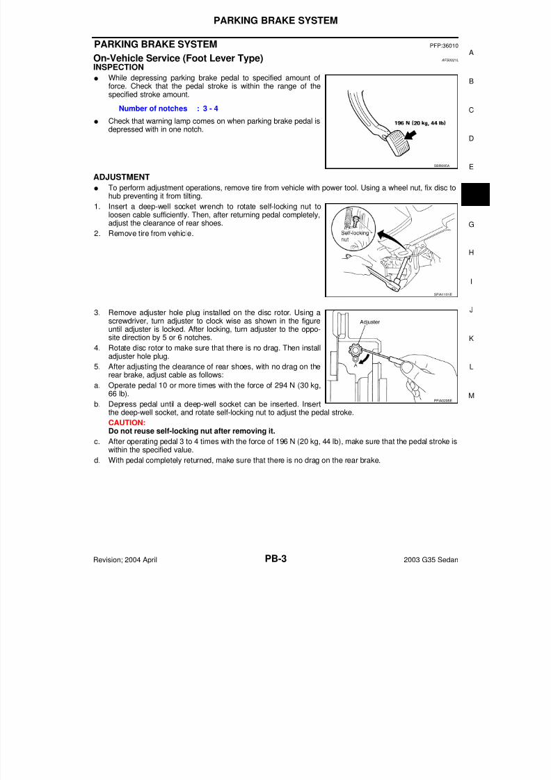
INSPECTION
While depressing parking brake pedal to specified amount offorce. Check that the pedal stroke is within the range of thespecified stroke amount.
Check that warning lamp comes on when parking brake pedal isdepressed with in one notch.
ADJUSTMENT
To perform adjustment operations, remove tire from vehicle with power tool. Using a wheel nut, fix disc tohub preventing it from tilting.
1. Insert a deep-well socket wrench to rotate self-locking nut to
loosen cable sufficiently. Then, after returning pedal completely,adjust the clearance of rear shoes.
2. Remove tire from vehicle.
3. Remove adjuster hole plug installed on the disc rotor. Using a
screwdriver, turn adjuster to clock wise as shown in the figureuntil adjuster is locked. After locking, turn adjuster to the oppo-site direction by 5 or 6 notches.
4. Rotate disc rotor to make sure that there is no drag. Then installadjuster hole plug.
5. After adjusting the clearance of rear shoes, with no drag on therear brake, adjust cable as follows:
a. Operate pedal 10 or more times with the force of 294 N (30 kg,66 lb).
b. Depress pedal until a deep-well socket can be inserted. Insertthe deep-well socket, and rotate self-locking nut to adjust the pedal stroke.
CAUTION:Do not reuse self-locking nut after removing it.
c. After operating pedal 3 to 4 times with the force of 196 N (20 kg, 44 lb), make sure that the pedal stroke iswithin the specified value.
d. With pedal completely returned, make sure that there is no drag on the rear brake.
Number of notches : 3 - 4
SBR695A
SFIA1101E
PFIA0295E
7/25/2019 03 G35 Parking Brake System
http://slidepdf.com/reader/full/03-g35-parking-brake-system 4/10PB-4
PARKING BRAKE SYSTEM
Revision; 2004 April 2003 G35 Sedan
On-Vehicle Service (Hand Lever Type) AFS0021M
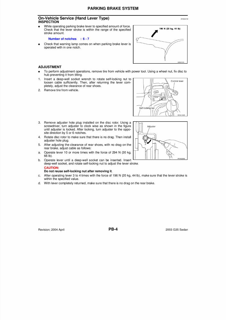
INSPECTION
While operating parking brake lever to specified amount of force.Check that the lever stroke is within the range of the specifiedstroke amount.
Check that warning lamp comes on when parking brake lever isoperated with in one notch.
ADJUSTMENT
To perform adjustment operations, remove tire from vehicle with power tool. Using a wheel nut, fix disc tohub preventing it from tilting.
1. Insert a deep-well socket wrench to rotate self-locking nut toloosen cable sufficiently. Then, after returning the lever com-pletely, adjust the clearance of rear shoes.
2. Remove tire from vehicle.
3. Remove adjuster hole plug installed on the disc rotor. Using ascrewdriver, turn adjuster to clock wise as shown in the figureuntil adjuster is locked. After locking, turn adjuster to the oppo-site direction by 5 or 6 notches.
4. Rotate disc rotor to make sure that there is no drag. Then installadjuster hole plug.
5. After adjusting the clearance of rear shoes, with no drag on therear brake, adjust cable as follows:
a. Operate lever 10 or more times with the force of 294 N (30 kg,66 lb).
b. Operate lever until a deep-well socket can be inserted. Insertdeep-well socket, and rotate self-locking nut to adjust the lever stroke.
CAUTION:Do not reuse self-locking nut after removing it.
c. After operating lever 3 to 4 times with the force of 196 N (20 kg, 44 lb), make sure that the lever stroke iswithin the specified value.
d. With lever completely returned, make sure that there is no drag on the rear brake.
Number of notches : 6 - 7
SBR073D
SFIA1102E
PFIA0295E
7/25/2019 03 G35 Parking Brake System
http://slidepdf.com/reader/full/03-g35-parking-brake-system 5/10
PARKING BRAKE CONTROL
PB-5
C
D
E
G
H
I
J
K
L
M
A
B
PB
Revision; 2004 April 2003 G35 Sedan
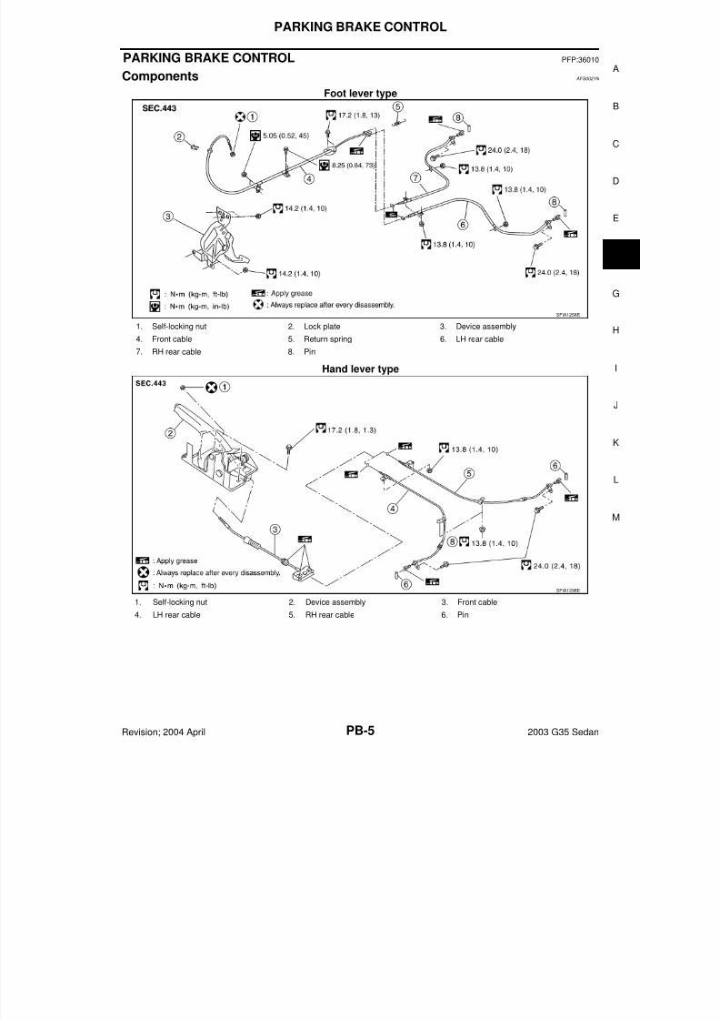
PARKING BRAKE CONTROL PFP:36010
Components AFS0021N
Foot lever type
Hand lever type
SFIA1258E
1. Self-locking nut 2. Lock plate 3. Device assembly
4. Front cable 5. Return spring 6. LH rear cable
7. RH rear cable 8. Pin
SFIA1298E
1. Self-locking nut 2. Device assembly 3. Front cable
4. LH rear cable 5. RH rear cable 6. Pin
7/25/2019 03 G35 Parking Brake System
http://slidepdf.com/reader/full/03-g35-parking-brake-system 6/10PB-6
PARKING BRAKE CONTROL
Revision; 2004 April 2003 G35 Sedan
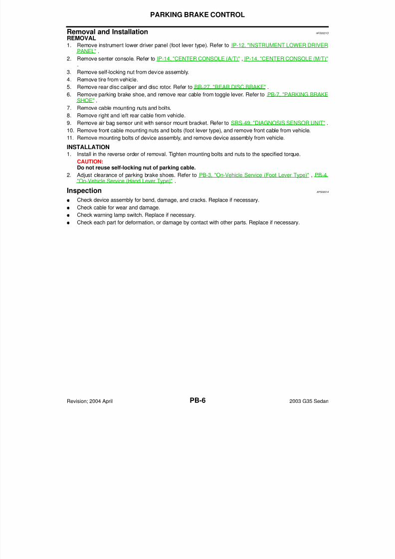
Removal and Installation AFS0021O
REMOVAL1. Remove instrument lower driver panel (foot lever type). Refer to IP-12, "INSTRUMENT LOWER DRIVER
PANEL" .
2. Remove senter console. Refer to IP-14, "CENTER CONSOLE (A/T)" , IP-14, "CENTER CONSOLE (M/T)".
3. Remove self-locking nut from device assembly.
4. Remove tire from vehicle.
5. Remove rear disc caliper and disc rotor. Refer to BR-27, "REAR DISC BRAKE" .
6. Remove parking brake shoe, and remove rear cable from toggle lever. Refer to PB-7, "PARKING BRAKESHOE" .
7. Remove cable mounting nuts and bolts.
8. Remove right and left rear cable from vehicle.
9. Remove air bag sensor unit with sensor mount bracket. Refer to SRS-49, "DIAGNOSIS SENSOR UNIT" .
10. Remove front cable mounting nuts and bolts (foot lever type), and remove front cable from vehicle.
11. Remove mounting bolts of device assembly, and remove device assembly from vehicle.
INSTALLATION
1. Install in the reverse order of removal. Tighten mounting bolts and nuts to the specified torque.CAUTION:Do not reuse self-locking nut of parking cable.
2. Adjust clearance of parking brake shoes. Refer to PB-3, "On-Vehicle Service (Foot Lever Type)" , PB-4,"On-Vehicle Service (Hand Lever Type)" .
Inspection AFS00014
Check device assembly for bend, damage, and cracks. Replace if necessary.
Check cable for wear and damage.
Check warning lamp switch. Replace if necessary.
Check each part for deformation, or damage by contact with other parts. Replace if necessary.
7/25/2019 03 G35 Parking Brake System
http://slidepdf.com/reader/full/03-g35-parking-brake-system 7/10
PARKING BRAKE SHOE
PB-7
C
D
E
G
H
I
J
K
L
M
A
B
PB
Revision; 2004 April 2003 G35 Sedan
PARKING BRAKE SHOE PFP:44060
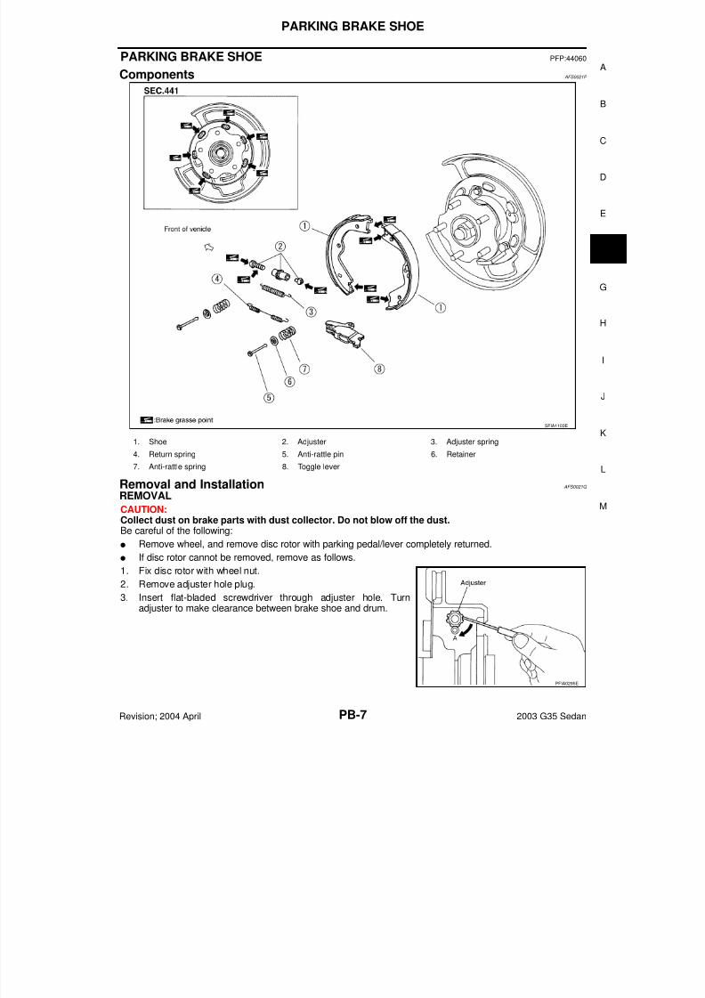
Components AFS0021P
Removal and Installation AFS0021Q
REMOVAL
CAUTION:Collect dust on brake parts with dust collector. Do not blow off the dust.Be careful of the following:
Remove wheel, and remove disc rotor with parking pedal/lever completely returned. If disc rotor cannot be removed, remove as follows.
1. Fix disc rotor with wheel nut.
2. Remove adjuster hole plug.
3. Insert flat-bladed screwdriver through adjuster hole. Turnadjuster to make clearance between brake shoe and drum.
SFIA1103E
1. Shoe 2. Adjuster 3. Adjuster spring
4. Return spring 5. Anti-rattle pin 6. Retainer
7. Anti-rattle spring 8. Toggle lever
PFIA0295E
7/25/2019 03 G35 Parking Brake System
http://slidepdf.com/reader/full/03-g35-parking-brake-system 8/10PB-8
PARKING BRAKE SHOE
Revision; 2004 April 2003 G35 Sedan
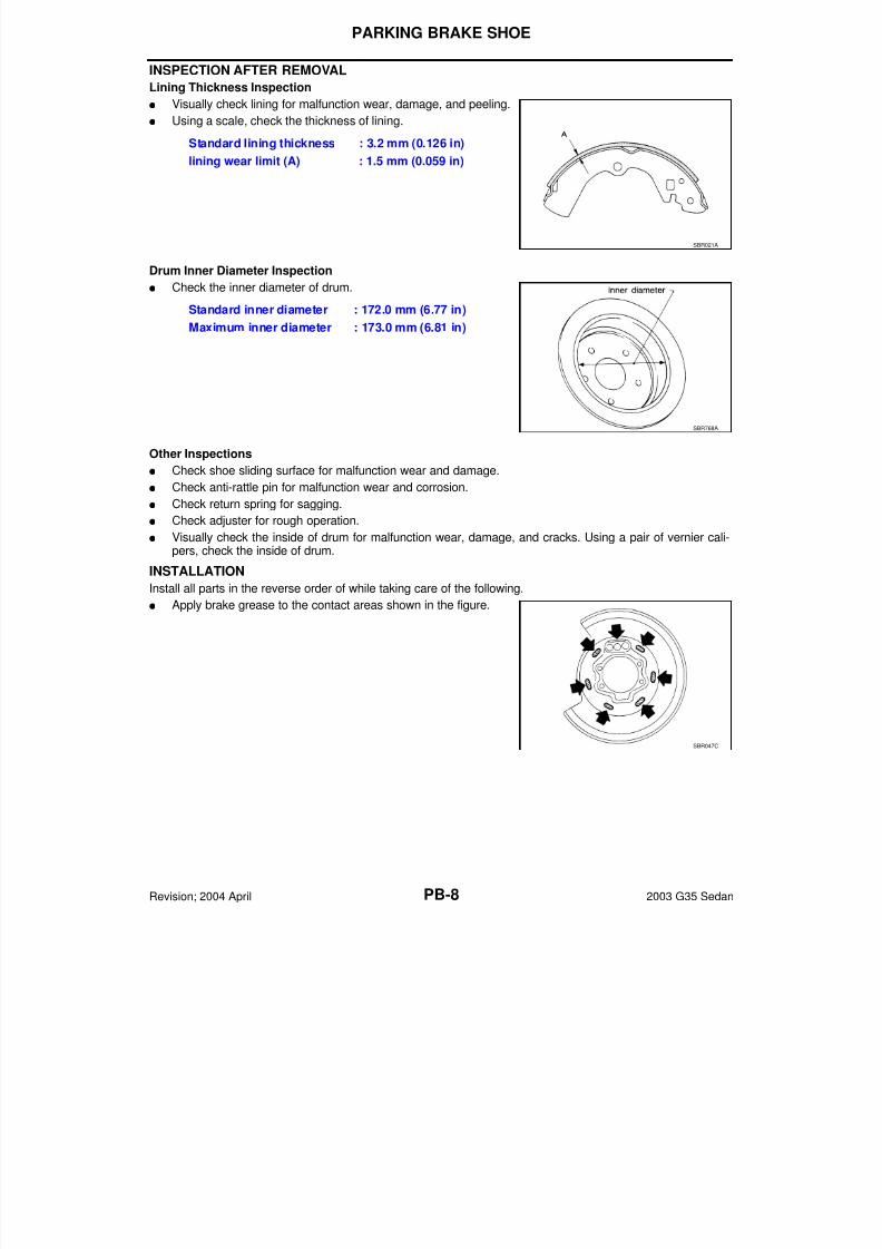
INSPECTION AFTER REMOVAL
Lining Thickness Inspection
Visually check lining for malfunction wear, damage, and peeling.
Using a scale, check the thickness of lining.
Drum Inner Diameter Inspection
Check the inner diameter of drum.
Other Inspections
Check shoe sliding surface for malfunction wear and damage.
Check anti-rattle pin for malfunction wear and corrosion.
Check return spring for sagging.
Check adjuster for rough operation.
Visually check the inside of drum for malfunction wear, damage, and cracks. Using a pair of vernier cali-pers, check the inside of drum.
INSTALLATION
Install all parts in the reverse order of while taking care of the following.
Apply brake grease to the contact areas shown in the figure.
Standard lining thickness : 3.2 mm (0.126 in)
lining wear limit (A) : 1.5 mm (0.059 in)
SBR021A
Standard inner diameter : 172.0 mm (6.77 in)
Maximum inner diameter : 173.0 mm (6.81 in)
SBR768A
SBR047C
7/25/2019 03 G35 Parking Brake System
http://slidepdf.com/reader/full/03-g35-parking-brake-system 9/10
PARKING BRAKE SHOE
PB-9
C
D
E
G
H
I
J
K
L
M
A
B
PB
Revision; 2004 April 2003 G35 Sedan
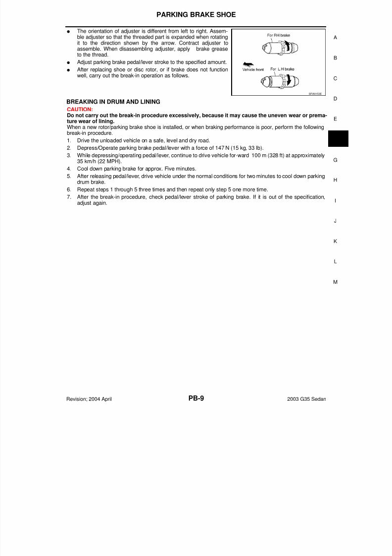
The orientation of adjuster is different from left to right. Assem-ble adjuster so that the threaded part is expanded when rotatingit to the direction shown by the arrow. Contract adjuster toassemble. When disassembling adjuster, apply brake greaseto the thread.
Adjust parking brake pedal/lever stroke to the specified amount.
After replacing shoe or disc rotor, or if brake does not function
well, carry out the break-in operation as follows.
BREAKING IN DRUM AND LINING
CAUTION:Do not carry out the break-in procedure excessively, because it may cause the uneven wear or prema-ture wear of lining.When a new rotor/parking brake shoe is installed, or when braking performance is poor, perform the followingbreak-in procedure.
1. Drive the unloaded vehicle on a safe, level and dry road.
2. Depress/Operate parking brake pedal/lever with a force of 147 N (15 kg, 33 lb).
3. While depressing/operating pedal/lever, continue to drive vehicle for-ward 100 m (328 ft) at approximately35 km/h (22 MPH).
4. Cool down parking brake for approx. Five minutes.
5. After releasing pedal/lever, drive vehicle under the normal conditions for two minutes to cool down parkingdrum brake.
6. Repeat steps 1 through 5 three times and then repeat only step 5 one more time.
7. After the break-in procedure, check pedal/lever stroke of parking brake. If it is out of the specification,adjust again.
SFIA0153E
7/25/2019 03 G35 Parking Brake System
http://slidepdf.com/reader/full/03-g35-parking-brake-system 10/10PB 10
SERVICE DATA AND SPECIFICATIONS (SDS)
SERVICE DATA AND SPECIFICATIONS (SDS) PFP:00030
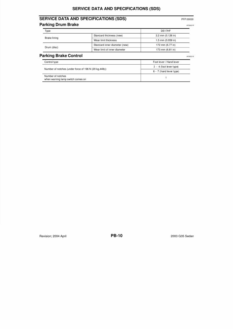
Parking Drum Brake AFS0021R
Parking Brake Control AFS0021S
Type DS17HF
Brake liningStandard thickness (new) 3.2 mm (0.126 in)
Wear limit thickness 1.5 mm (0.059 in)
Drum (disc) Standard inner diameter (new) 172 mm (6.77 in)
Wear limit of inner diameter 173 mm (6.81 in)
Control type Foot lever / Hand lever
Number of notches (under force of 196 N (20 kg,44lb))3 - 4 (foot lever type)
6 - 7 (hand lever type)
Number of notches
when warning lamp switch comes on1