【英03-2】【2018.01】tawers (tstmtl-wgⅢ) (e) welding parameter database developed through our...
TRANSCRIPT
TS series TM seriesSeparate Type Through-Arm Type External Type
TL series
Continuously Evolving TAWERS!
TAWERS 6 Axis Articulated Arc Welding Robots
January 2018
Series
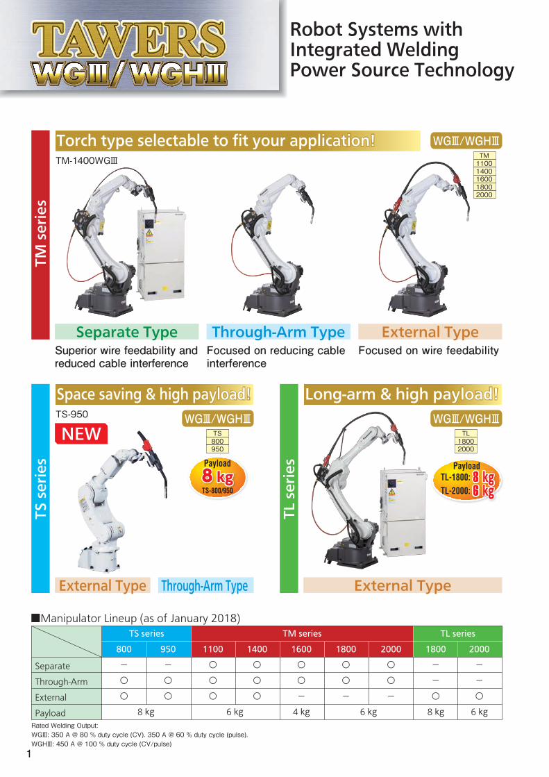
Rated Welding Output:WGⅢ: 350 A @ 80 % duty cycle (CV). 350 A @ 60 % duty cycle (pulse).WGHⅢ: 450 A @ 100 % duty cycle (CV/pulse)
TM-1400WGⅢ
TS-950
Through-Arm Type External Type
Through-Arm TypeExternal Type
Separate TypeFocused on reducing cable interference
Focused on wire feedabilitySuperior wire feedability and reduced cable interference
800950
WGⅢ/WGHⅢTS
■Manipulator Lineup (as of January 2018)
External Type
Robot Systems with Integrated Welding Power Source Technology
Torch type selectable to fit your application!Torch type selectable to fit your application!11001400160018002000
WGⅢ/WGHⅢTM
18002000
WGⅢ/WGHⅢTL
Separate
Through-Arm
External
Payload
1100
○
○
○
1400
○
○
○
6 kg
TM series
1600
○
○
-
4 kg
1800
-
-
○
8 kg
2000
-
-
○
6 kg
TL seriesTS series
1800
○
○
-
6 kg
2000
○
○
-
800
-
○
○
950
-
○
○
8 kg
TM series
TL series
TS series
Long-arm & high payload!Long-arm & high payload!Space saving & high payload!Space saving & high payload!
8 kgTL-1800: 88 kgkkg6 kgTL-2000:
Payload8 kgPayload
TS-800/950
1

New type welding robot achieveseven higher quality welds.
Power cable inter-ference can occur depending on the welding position.
An example of circumferential welding
Gentle curve of flexible conduit between wire feeder and torch body achieves stable wire feeding.
Interference
R=large
[Separate Type]
[Separate Type]
[Conventional Type]
[Conventional Type]
R=small
Reducedinterference
A variety of features specialized for arc weldingA variety of features specialized for arc welding
Featuree2
Featuree1 Enhanced Basic Performance Featuree3 Structure Specialized for Welding
Cantilever Structure
Increased Motion Speed
makes arm compact and improves accessibility to workpieces.
TM-1400: Speed of main 3 axes increased by 22 % on average. (approx. 42°/s more than TA type)
Extended ReachTM-1400: 1 437 mm (63 mm more than TA type)
Arm Specialized for Welding
Featuree1 External Flexible Conduit
Featuree2 Through-Arm Power Cable
Reduces target position error at weld start and end points!Through-arm power
cable reduces cable interference.
Suppressestwist of wire!
Torch cable
Flexible conduit
(TS/TM)
(TM/TL) (TM/TL)
[Option]Internal Flexible Conduit (for wire feed)**
Gas hose (with valve)
Welding power cable
[Option] Internal Flexible Conduit (for wire feed)**
**For use with drum packing wire only.
Manipulator-Controller cable (motor power)
Manipulator-Controller cable (control)
Clean Cable Management!
Revolutionary new type of arc welding robot with advantages of both Through-Arm Type and External Type.
A third choice̶Separate Type (TM series)In addition to Through-Arm Type and External Type,
itFlexible condui
.
High Wire FeedabilityLess Cable Interference
2
WGⅢ WGHⅢ
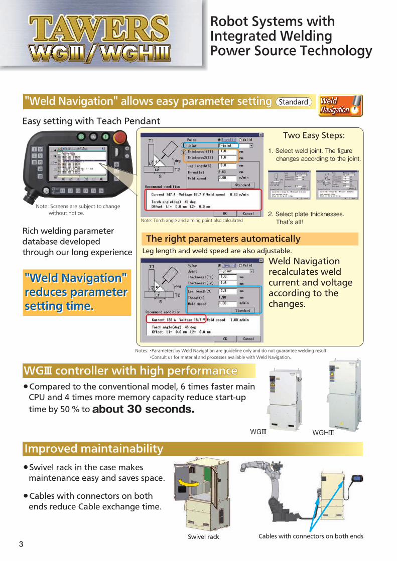
Swivel rack Cables with connectors on both ends
WGⅢ controller with high performance●Compared to the conventional model, 6 times faster main CPU and 4 times more memory capacity reduce start-up time by 50 % to about 30 seconds.
WGⅢ controller with high performance
"Weld Navigation" allows easy parameter setting
Easy setting with Teach Pendant
Leg length and weld speed are also adjustable.Weld Navigation recalculates weld current and voltage according to the changes.
Standard
1. Select weld joint. The figure changes according to the joint.
Two Easy Steps:
2. Select plate thicknesses. That's all!
Notes: ・Parameters by Weld Navigation are guideline only and do not guarantee welding result. ・Consult us for material and processes available with Weld Navigation.
The right parameters automatically
"Weld Navigation" reduces parameter setting time.
"Weld Navigation" allows easy parameter setting
"Weld Navigation" reduces parameter setting time.
①②
Note: Torch angle and aiming point also calculated
Note: Screens are subject to change without notice.
Improved maintainability●Swivel rack in the case makes maintenance easy and saves space.
●Cables with connectors on both ends reduce Cable exchange time.
Robot Systems with Integrated Welding Power Source Technology
Rich welding parameter database developed through our long experience
3
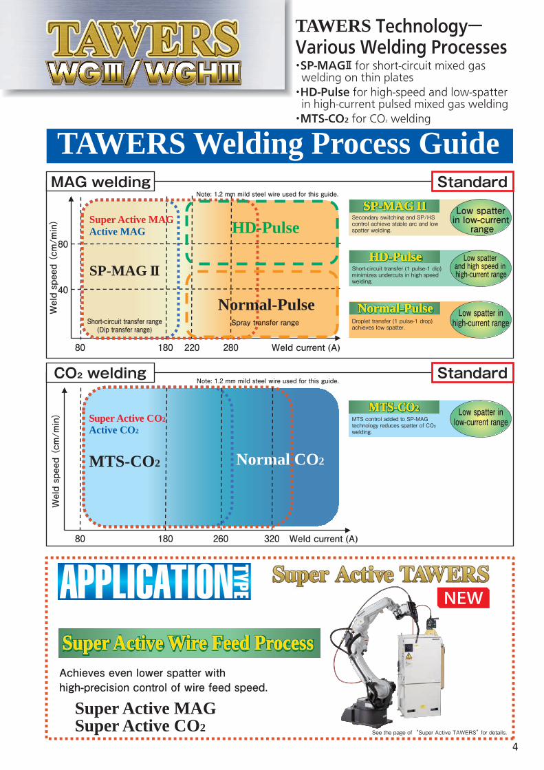
See the page of “Super Active TAWERS” for details.
MTS-CO2
Active CO2
Normal CO2
Super Active CO2
SP-MAG II
Active MAGSuper Active MAG
SP-MAG IISP-MAG IISP-MAG IISP-MAG IISP-MAG II
HD-Pulse
Normal-Pulse
Super Active MAGSuper Active CO2
TAWERS Welding Process Guide
MTS-CO2MTS-CO2MTS-CO2MTS-CO2MTS-CO2
HD-PulseHD-PulseHD-PulseHD-PulseHD-Pulse
Normal-PulseNormal-PulseNormal-PulseNormal-PulseNormal-Pulse
MAG welding
CO₂ welding
Standard
Standard
Short-circuit transfer range(Dip transfer range)
Secondary switching and SP/HS control achieve stable arc and low spatter welding.
Short-circuit transfer (1 pulse-1 dip) minimizes undercuts in high speedwelding.
Droplet transfer (1 pulse-1 drop) achieves low spatter.
MTS control added to SP-MAG technology reduces spatter of CO₂ welding.
80
80
40
180 220 Weld current (A)
Weld current (A)80 180 260
Weld speed
(cm/min
)
Weld speed
(cm/min
)
Spray transfer range
Note: 1.2 mm mild steel wire used for this guide.
Note: 1.2 mm mild steel wire used for this guide.
Low spatter in low-current range
Low spatter inlow-current range
Achieves even lower spatter with high-precision control of wire feed speed.
Low spatter inhigh-current range
Low spatter and high speed in high-current range
TAWERS Technology―Various Welding Processes・SP-MAGⅡ for short-circuit mixed gas welding on thin plates・HD-Pulse for high-speed and low-spatter in high-current pulsed mixed gas welding・MTS-CO₂ for CO₂ welding
Super Active Wire Feed ProcessSuper Active Wire Feed ProcessSuper Active Wire Feed ProcessSuper Active Wire Feed ProcessSuper Active Wire Feed Process
280
320
4
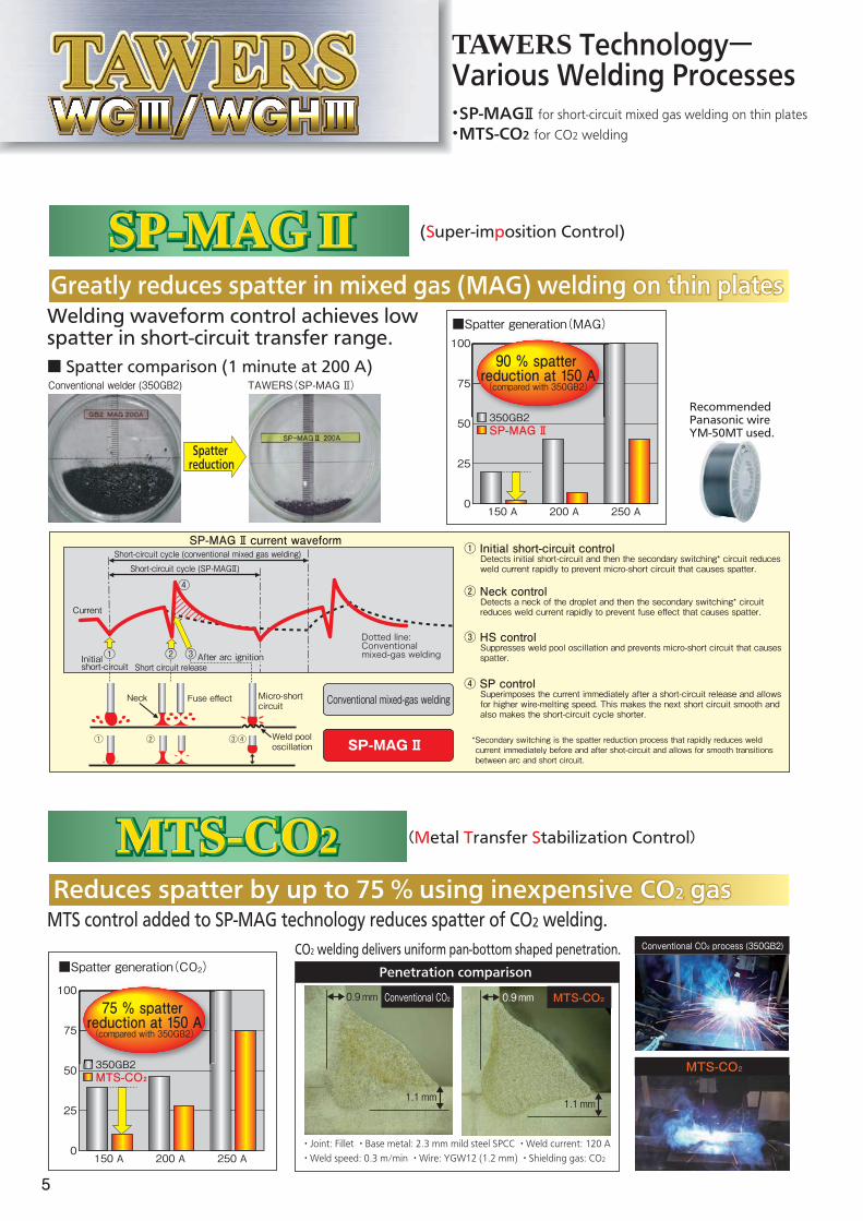
Greatly reduces spatter in mixed gas (MAG) welding on thin platesWelding waveform control achieves low spatter in short-circuit transfer range.
Reduces spatter by up to 75 % using inexpensive CO2 gasMTS control added to SP-MAG technology reduces spatter of CO2 welding.
CO2 welding delivers uniform pan-bottom shaped penetration.
(Super-imposition Control)
(Metal Transfer Stabilization Control)
SP-MAG IISP-MAG IISP-MAG IISP-MAG IISP-MAG II
・Joint: Fillet ・Base metal: 2.3 mm mild steel SPCC ・Weld current: 120 A・Weld speed: 0.3 m/min ・Wire: YGW12 (1.2 mm) ・Shielding gas: CO2
① Initial short-circuit control
② Neck control
③ HS control Suppresses weld pool oscillation and prevents micro-short circuit that causes spatter.
*Secondary switching is the spatter reduction process that rapidly reduces weld current immediately before and after shot-circuit and allows for smooth transitions between arc and short circuit.
④ SP control Superimposes the current immediately after a short-circuit release and allows for higher wire-melting speed. This makes the next short circuit smooth and also makes the short-circuit cycle shorter.
Detects initial short-circuit and then the secondary switching* circuit reduces weld current rapidly to prevent micro-short circuit that causes spatter.
Detects a neck of the droplet and then the secondary switching* circuit reduces weld current rapidly to prevent fuse effect that causes spatter.
SP-MAG Ⅱ current waveform
②
②
③
③
④
④
Micro-short circuit
Weld pool oscillation
Neck Fuse effect
Conventional CO₂ process (350GB2)
Penetration comparison
MTS-CO₂
0.9mm 0.9mm
1.1mm 1.1mm
Conventional CO₂ MTS-CO₂
■ Spatter comparison (1 minute at 200 A)
Recommended Panasonic wireYM-50MT used.
MTS-CO2MTS-CO2MTS-CO2MTS-CO2MTS-CO2
Spatter reduction
Short-circuit cycle (conventional mixed gas welding)Short-circuit cycle (SP-MAGⅡ)
①
①
Current
TAWERS Technology―Various Welding Processes・SP-MAGⅡ for short-circuit mixed gas welding on thin plates・MTS-CO2 for CO2 welding
Conventional welder (350GB2) TAWERS(SP-MAG Ⅱ)
Dotted line: Conventional mixed-gas welding
Greatly reduces spatter in mixed gas (MAG) welding on thin plates
Initial short-circuit Short circuit release
After arc ignition
Conventional mixed-gas welding
SP-MAG Ⅱ
Reduces spatter by up to 75 % using inexpensive CO2 gas
150 A 200 A 250 A0
25
50
75
100
90 % spatter reduction at 150 A(compared with 350GB2)
350GB2SP-MAG Ⅱ
■Spatter generation(MAG)
150 A 200 A 250 A0
25
50
75
100
350GB2MTS-CO₂
■Spatter generation(CO2)
350GB2
75 % spatter reduction at 150 A(compared with 350GB2)
5

Achieves high-speed pulsed welding
■HD-Pulse advantages:
Short and narrow arc prevents undercuts during high-speed welding.
(Hyper Dip-Pulse Control)HD-PulseHD-PulseHD-PulseHD-PulseHD-Pulse
●Preventing undercuts during high speed welding.
●Dip (Short circuit) transfer enabling lower heat input with better gap handling capability.
●Precisely controlled dip timing reducing spatter.
1 drop by 1 pulse (Drop transfer)
HD Pulse Normal Pulse
Normal Pulse
1 dip by 1 pulse (Short-circuit transfer)
●SP-MAG Ⅱ disadvantage: Spatter in high-current range.
●Normal-pulse disadvantage: Undercuts in high-speed welding.
HD Pulse
Gap:0.4 mm
Gap:1.5 mm
Undercut
Undercut
・Base metal thickness: 2.3 mm ・Weld current: 300 A ・Weld speed: 1.1 m/min
LongShortWideNarrow
DropDip(Short-circuit)
Concentrated arc
Weld process Normal-Pulse
good
excellent
good-fair
fair
fair
fair
fair
SP-MAG Ⅱ
goodWeld speed
Spatter
Penetration pattern
Undercut
Heat input
Gap handling
Overall
HD-Pulse
excellent
good
excellent
excellent
good
good
excellent
■High speed welding
■Type of the droplet transfer
Preventing undercuts with ideal penetration!
HD-Pulse process is ideal for high-current and high-speed welding.
TAWERS Technology―Various Welding Processes・Normal pulse for ultra-low spatter welding・HD-Pulse for high-speed and low-spatter welding
LongShortWideNarrow
good-fair
fair
fair
fair
fair
fair
■Spray transfer range: 280 A or more
6
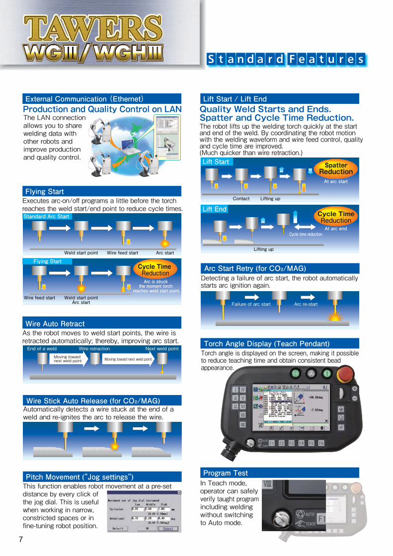
Detecting a failure of arc start, the robot automatically starts arc ignition again.
The LAN connection allows you to share welding data with other robots and improve production and quality control.
Automatically detects a wire stuck at the end of a weld and re-ignites the arc to release the wire.
Failure of arc start Arc re-start
Torch Angle Display (Teach Pendant)
Wire Auto RetractAs the robot moves to weld start points, the wire is retracted automatically; thereby, improving arc start.
Lift Start / Lift EndExternal Communication (Ethernet)
Program TestIn Teach mode, operator can safely verify taught program including welding without switching to Auto mode.
Pitch Movement ("Jog settings")
Moving toward next weld point
End of a weld Wire retraction Next weld point
Moving toward next weld point
Flying StartExecutes arc-on/off programs a little before the torch reaches the weld start/end point to reduce cycle times.
Wire Stick Auto Release (for CO₂/MAG)
Arc Start Retry (for CO₂/MAG)
Quality Weld Starts and Ends. Spatter and Cycle Time Reduction.The robot lifts up the welding torch quickly at the start and end of the weld. By coordinating the robot motion with the welding waveform and wire feed control, quality and cycle time are improved.(Much quicker than wire retraction.)
Contact Lifting up
Lifting up
Cycle time reduction
Lift Start
Lift End
Torch angle is displayed on the screen, making it possible to reduce teaching time and obtain consistent bead appearance.
This function enables robot movement at a pre-set distance by every click of the jog dial. This is useful when working in narrow, constricted spaces or in fine-tuning robot position.
Production and Quality Control on LAN
Standard Arc Start
Arc startWire feed startWeld start point
Flying Start
Wire feed start Weld start pointArc start
Arc is struck the moment torch
reaches weld start point.
Cycle Time Reduction
Cycle TimeReductionAt arc end
SpatterReductionAt arc start
7

Weld Data Management
Cooperative Multi-Robot ControlAllows cooperative control between two robots.
Compensates heat distortion or teaching error of odd-shaped work. Robots detects changes in wire extension and compensates automatically.
Big progress toward ideal production and quality control.Samples weld data with a interval of up to 50 micro seconds, allowing high-precision monitoring and status/error output. The data can be stored and used for quality control.
Monitors data such as weld current, voltage and wire feed speed constantly and warns when abnormality is detected.
Weld Monitor Standard
Auto Extension Control
Example of log data analysis
Available for defect rate reduction
Changes of average current/voltage
Wire target position misalignment caused by production lot change
9
120
110
100
90
Current (A)
80
70
6050
Voltage (V)
15
16
17
18
19
20
Output current
10 11 12Production time
14 15 16
Output voltage
More advanced welding system available Utilize features such as external communication and large capacity memory.
Condition A
Condition A
Condition B
Condition B・Weld current
・Wire feed speed
Torch movement【Spiral weaving movement】 ・Synchronizes weld current,
wire feed speed and weaving completely.
・Alternates condition A/B during weaving, which is ideal for welding of different thickness plates. (One for thin plate, the other for thick plate)
Synchronous Weaving Low Pulse (Spiral Weaving Included)
●Weld Monitoring (Expanded function) Up to 50 weld monitoring conditions can be defined.
●Weld Data Logging/Recording Data such as weld current, voltage and wire feed speed can be logged according to the preset triggers. The log data can be graphed on the teach pendant and recorded on SD memory card.
Weld Data Management Optional Software
Optional Software
Optional Software
Welding Data LogLogs data of weld sections. The log data can be saved for analysis.
8
15
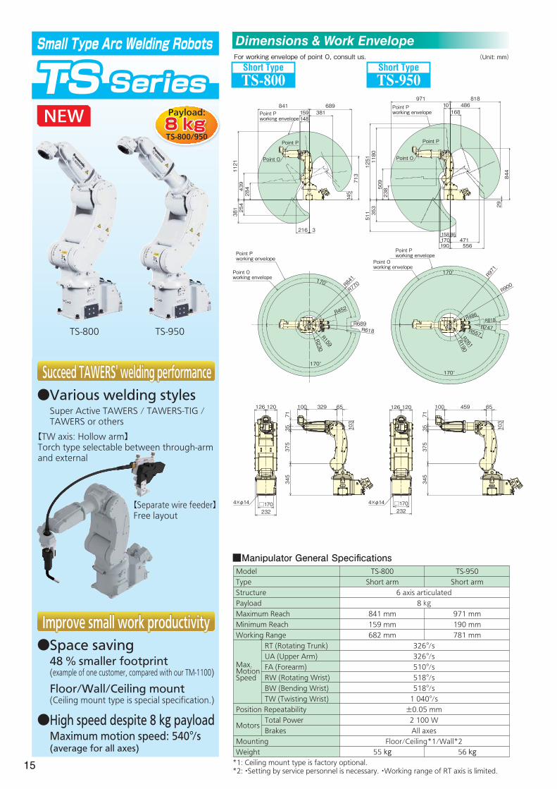
Small Type Arc Welding Robots
TS Series
TS-800 TS-950
Short Type
TS-800Short Type
TS-950
(Unit: mm)
■Manipulator General Specifications
For working envelope of point O, consult us.
*1: Ceiling mount type is factory optional. *2: ・Setting by service personnel is necessary. ・Working range of RT axis is limited.
841 689
1121
381
1251
511
1180
353
509
238
254
439
284
145
713 844
29
159148
381
216 3
Point P working envelope
971 818486
168101Point P
working envelope
158 86170 471190
170°
170°
170°
170°
556
126 120 100 329 65
□170232
□170232
4×φ14 4×φ14
345
375
35 103
100 459 65
103
71
345
375
3571
Point P working envelope
Point O working envelope
Point P working envelope
Point O working envelope
R841
R971
R900
R486 R818R747R557R261
R190
R770
R452
R689R618
R159
R230
Point P Point P
Point OPoint O
126 120
ModelTypeStructurePayloadMaximum ReachMinimum ReachWorking Range
Position Repeatability
Motors
MountingWeight
RT (Rotating Trunk)UA (Upper Arm)FA (Forearm)RW (Rotating Wrist)BW (Bending Wrist)TW (Twisting Wrist)
Total PowerBrakes
TS-800Short arm
841 mm159 mm682 mm
55 kg
TS-950Short arm
971 mm190 mm781 mm
56 kg
6 axis articulated8 kg
326°/s326°/s510°/s518°/s518°/s1 040°/s±0.05 mm2 100 WAll axes
Floor/Ceiling*1/Wall*2
Max. Motion Speed
Improve small work productivity●Space saving 48 % smaller footprint (example of one customer, compared with our TM-1100) Floor/Wall/Ceiling mount (Ceiling mount type is special specification.)●High speed despite 8 kg payload Maximum motion speed: 540°/s (average for all axes)
Succeed TAWERS' welding performance●Various welding styles Super Active TAWERS / TAWERS-TIG / TAWERS or others
【Separate wire feeder】Free layout
8 kgPayload:
TS-800/950
【TW axis: Hollow arm】Torch type selectable between through-arm and external
Dimensions & Work Envelope
16
170°
170°
Point Pworking range
Point Oworking range
R428R404
R1413
R1437
170°
170°
R418
R442 R1163R1139
Point Pworking range
Point Oworking range
170°
170°
R1785
R1489
R1465
R848R824R454R430 R1809
Point Oworking range
Point Pworking range
Point P
Point O
1437404200 210
5561117
244 291369 456
803 258 263
1034
50119
220
1697
256327
162179
1163 82441826130
2909351423
545 321
262
Point Pworking range
Point P
Point O
1809 1489
2069
1204
421
1121245
430375
545
445
824
223
Point P
Point Pworking range
Point O
R1319R1295
R1639R1615
R768R744
R537
R513
170°
170°
Point Pworking range
Point Oworking range
13191639
1899
1005
90361
513409 208
744
1245
446
69495Point P
working range
Point P
Point O
420
580
21024
125 850 160
20
□ 300φ370
181.4
131120 7563
70±0.2
4-φ18
4×M8×1.25 Depth: 20
420
580
160131120
125 640
24210
89
7563
□ 300
181.4
2070±0.2
4×M8×1.25 Depth: 20
φ3704-φ18
24210
131 125121
420
400
540 160
□ 300φ370
181.4
2070±0.2
4×M8×1.25 Depth: 20
4-φ18
24210
750
420
70±0.2
30
125 850 160
5875
89
4×M8×1.25
131120
196
□ 300φ370
4-φ18
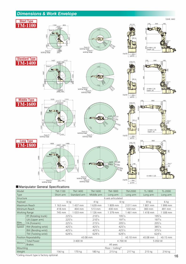
Short Type
TM-1100
Standard Type
TM-1400
Middle Type
TM-1600
Long Type
TM-1800
Dimensions & Work Envelope(Unit: mm)
Manipulator General SpecificationsModelTypeStructurePayloadMaximum ReachMinimum ReachWorking Range
Position Repeatability
Motors
MountingWeight
RT (Rotating trunk)UA (Upper arm)FA (Forearm)RW (Rotating wrist)BW (Bending wrist)TW (Twisting wrist)
Total PowerBrakes
TM-1100Short arm
1 163 mm 418 mm 745 mm
156 kg
TM-1400Standard arm
1 437 mm0 404 mm1 033 mm
3 400 W
170 kg
TM-1800Long arm
1 809 mm430 mm1 379 mm
215 kg
195°/s197°/s205°/s425°/s425°/s629°/s
6 kg
4 700 W
TM-2000Long arm
2 011 mm550 mm1 461 mm
±0.10 mm
217 kg
6 axis articulated
All axesFloor / Ceiling*
TM-1600Middle arm
4 kg1 639 mm513 mm1 126 mm210°/s210°/s215°/s425°/s425°/s629°/s
180 kg
±0.08 mm
TL-1800Long arm
8 kg1 801 mm383 mm1 418 mm
±0.08 mm
215 kg
195°/s197°/s205°/s385°/s375°/s624°/s
5 050 W
TL-2000Long arm
6 kg1 999 mm491 mm1 508 mm
±0.15 mm
216 kg
6 kg
225°/s225°/s225°/s425°/s425°/s629°/s
*Ceiling mount type is factory optional.
Max. Motion Speed

17
170°
170°
R1481
R1421
R1801R1741
R517R457R443R383
Point Oworking range
Point Pworking range
R1679
R1619
R1939
Point Oworking range
Point Pworking range
R1999
R662R602
R551R491
170°
170°
1801 1481
2061
1196311
992
38371
537
471
457
203
Point P
435390Point P
working range
Point O
1999 1679
2259
1394
406
1234
491
735
669
602
41
Point P
346390Point P
working range
Point O
60140
750
420
155 820 160
4×M8×1.25
70±0.230
□ 300φ370
141
196
4-φ18
60140
750
420
155 1020 160
4×M8×1.25
70±0.230
□ 300
φ370
141
196
4-φ18
Long Type
TL-1800
Long Type
TL-2000
Long Type
TM-2000
Dimensions & Work Envelope(Unit: mm)
■Controller / Welder Technical Specifications
*Protruding portions not included. **Teach pendant and connection cable not included. Note: For details on the power connection, refer to "Connecting primary power source" in the arc welding robot controller manual.
■Teach Pendant
■Controller (with power unit)553 550
178
290 76
1181(WGHⅢ=1407)
(mm)
(mm)
WGⅢ
WGHⅢ
WGⅢ
WGHⅢ
Model
Input Power
Input and Output
Memory Capacity
Position Control
External Memory
Control Axes
Welding ProcessOutput Current RangeOutput Voltage Range
Duty Cycle
Dimensions*Weight**
WGⅢ
3 phase, 200 V AC±20 V AC, 22 kVA, 50/60 Hz
3 phase, 200 V AC±20 V AC, 30.5 kVA, 50/60 Hz
40 000 points
Software servo control
Teach Pendant: one SD memory card slot, two USB 2.0 ports (USB 2.0. Hi-Speed not supported)
CO2 / MAG / Stainless steel MIG / Pulse MAG / Stainless pulse MIG50/60 Hz (Max. current at servo on: 246 A/5.6 ms)
6 axes simultaneously (Max. 27 axes)
Input: 40 points (Optionally expandable up to 2048 points)Output: 40 points (Optionally expandable up to 2048 points)
30 to 350 A DC12 to 36 V DC
CV: 80 % @ 350 A Pulse: 60 % @ 350 A
30 to 450 A DC12 to 42 V DC
100 %
W 553 mm x D 550 mm x H 1181 mmWGHⅢ
W 553 mm x D 550 mm x H 1407 mm135 kg 171 kg
2011 1691550
3761002
2271
1406522
1415
747
624
49
Point O
Point P
Point Pworking range
170°
170°
R550
R574
R1002
R1026
R1987
R2011
R1667
R1691
Point Oworking range
Point Pworking range φ370
196
120131
24210
750
420
125 1057
70±0.230
89
160
5875
□300
4×M8×1.25
4-φ18

18
Large Robot Series (GⅢ Controller)
Great material handling capability!
Coordinated multi-robot
movement for flexible
system without jig.
■Manipulator General Specifications
●Coordinated movement with WGⅢ/GⅢ robot(s)
Allows to build flexible system without jig.
Maximum configuration: ・Arc welding robot x 2・Large robot x 1
●GⅢ controller for large robotsSame operation, maintenance and options as conventional robots
ModelTypePayload
Position RepeatabilityWeight
Referenced from HorizontalReferenced from upper arm
WorkingRange
Max.MotionSpeed
HS-220GⅢ
220 kg±178 °
-65 °~ +80 °-130 °~ +230 °-73°~ +190 °±360 °±128 °±360 °120°/s105°/s110°/s145°/s145°/s220°/s
955 kg
YS-080GⅢ
80 kg±180 °
-80 °~ +155 °-140 °~ +230 °-80 °~ +180 °±360 °±125 °±360 °170°/s140°/s160°/s230°/s230°/s350°/s
645 kg
RT (Rotating trunk)UA (Upper arm)
FA (Forearm)
RW (Rotating wrist)BW (Bending wrist)TW (Twisting wrist)RT (Rotating trunk)UA (Upper arm)FA (Forearm)RW (Rotating wrist)BW (Bending wrist)TW (Twisting wrist)
Connection Diagram
*For use with drum packing wire only.
TM-1400WGⅢ (Separate Type)
Drum hood (optional)
Gas regulator (optional)
Manipulator-Controllercable unit
Welding power cable
*
Gas hose
Flexible conduit (for wire feed)
YS-080GⅢ HS-220GⅢ
6 axis articulated robot
±0.15 mm