02.point-to-point links, hdlc, ppp, and frame relay
DESCRIPTION
02.Point-To-Point Links, HDLC, PPP, And Frame RelayTRANSCRIPT
The Ultimate CCNA Study Package - ICND 2 Chris Bryant, CCIE #12933 http://www.thebryantadvantage.com
Back To Index
Point-To-Point Links, HDLC, PPP, AndFrame Relay
Overview
NOTE: As of July 1, 2009, it is strongly recommended to all CCENT test-takers that you study BOTH the Frame Relay material in the ICND1 andICND2 sections of this course.
HDLC And PPP
With a point-to-point WAN link, we've got two options for encapsulation -HDLC and PPP. (HDLC and PPP do not run on LANs, so you won't beconfiguring these on Ethernet interfaces.)
HDLC And PPP
PPP Features
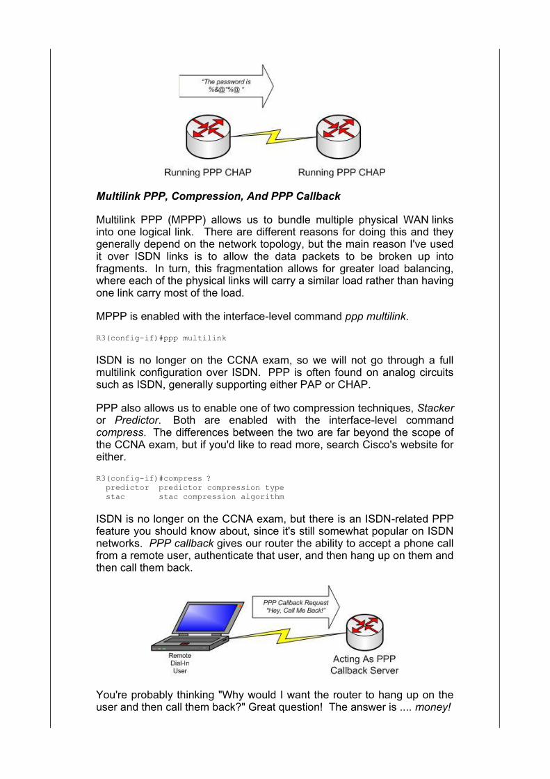
PAP And CHAP
Multilink PPP, Compression, And Callback
The Link Control Protocol
An Introduction To Frame Relay
Frame Relay LMI
DLCIs, Frame Maps, and Inverse ARP
Frame Subinterfaces And Split Horizon
FECN, BECN, and DE Bits
"Hot Spots And Gotchas"
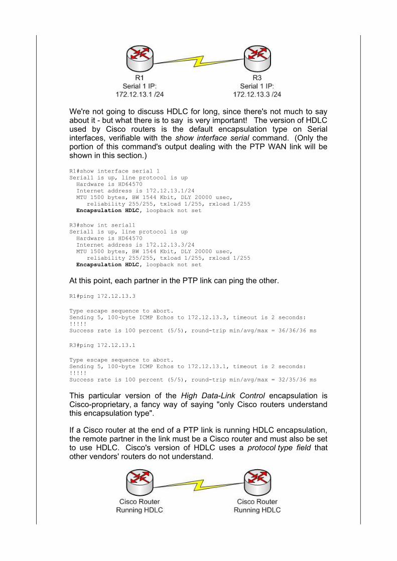
We're not going to discuss HDLC for long, since there's not much to sayabout it - but what there is to say is very important! The version of HDLCused by Cisco routers is the default encapsulation type on Serialinterfaces, verifiable with the show interface serial command. (Only theportion of this command's output dealing with the PTP WAN link will beshown in this section.)
R1#show interface serial 1Serial1 is up, line protocol is up Hardware is HD64570 Internet address is 172.12.13.1/24 MTU 1500 bytes, BW 1544 Kbit, DLY 20000 usec, reliability 255/255, txload 1/255, rxload 1/255 Encapsulation HDLC, loopback not set
R3#show int serial1Serial1 is up, line protocol is up Hardware is HD64570 Internet address is 172.12.13.3/24 MTU 1500 bytes, BW 1544 Kbit, DLY 20000 usec, reliability 255/255, txload 1/255, rxload 1/255 Encapsulation HDLC, loopback not set
At this point, each partner in the PTP link can ping the other.
R1#ping 172.12.13.3
Type escape sequence to abort.Sending 5, 100-byte ICMP Echos to 172.12.13.3, timeout is 2 seconds:!!!!!Success rate is 100 percent (5/5), round-trip min/avg/max = 36/36/36 ms
R3#ping 172.12.13.1
Type escape sequence to abort.Sending 5, 100-byte ICMP Echos to 172.12.13.1, timeout is 2 seconds:!!!!!Success rate is 100 percent (5/5), round-trip min/avg/max = 32/35/36 ms
This particular version of the High Data-Link Control encapsulation isCisco-proprietary, a fancy way of saying "only Cisco routers understandthis encapsulation type".
If a Cisco router at the end of a PTP link is running HDLC encapsulation,the remote partner in the link must be a Cisco router and must also be setto use HDLC. Cisco's version of HDLC uses a protocol type field thatother vendors' routers do not understand.
If one of the routers is running another encapsulation type, the physicalinterfaces will still be up, but the line protocol will go down and IPconnectivity will be lost. To illustrate, I'll change the encapsulation type onR3's Serial1 interface to the Point-To-Point Protocol (PPP).
R3(config-if)#exitR3(config)#int serial 1R3(config-if)#encapsulation ppp
A few seconds later, the line protocol goes down on R3.
2d04h: %SYS-5-CONFIG_I: Configured from console by console2d04h: %LINEPROTO-5-UPDOWN: Line protocol on Interface Serial1, changedstate to down
One way to detect an encapsulation mismatch is to look at theconfiguration itself. If you don't specifically see PPP or Frame Relaymentioned in the config, the interface is running the default - HDLC.
interface Serial0 < no encapsulation mentioned, is running HDLC > no ip address shutdown!interface Serial1 no ip address encapsulation ppp shutdown
A more efficient manner of detecting a mismatch is show interface serial,since this command gives you more interface-specific informationregarding the issue. Here, show interface serial 1 on both routers verifiesthat the physical interface is up, but the line protocol is down. IPconnectivity is lost.
R3#show interface serial 1Serial1 is up, line protocol is down
R3#ping 172.12.13.1
Type escape sequence to abort.Sending 5, 100-byte ICMP Echos to 172.12.13.1, timeout is 2 seconds:.....Success rate is 0 percent (0/5)
R1#show interface serial 1Serial1 is up, line protocol is down
R1#ping 172.12.13.3
Type escape sequence to abort.Sending 5, 100-byte ICMP Echos to 172.12.13.3, timeout is 2 seconds:.....Success rate is 0 percent (0/5)
The encapsulation mismatch has brought the line protocol down, and tobring it back up, we simply need to make the encapsulation types matchagain. Before doing so, let's take a detailed look at PPP.
PPP Features
Even thought the default setting of a Cisco serial interface is to use HDLC
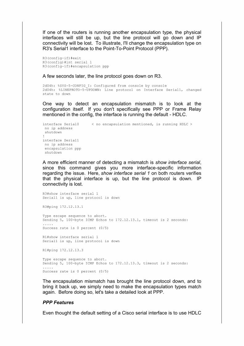
encapsulation, you're generally going to change that encap type to PPP. PPP is supported by non-Cisco vendors where HDLC is not, so if you'vegot a multivendor environment, you must use PPP instead of HDLC.
PPP offers many features that HDLC does not, including the following:
Authentication through the use of the Password AuthenticationProtocol (PAP) and the Challenge-Handshake AuthenticationProtocol (CHAP)
Compression capabilities through the use of Stacker or Predictor
PPP Multilink, the ability to bundle multiple physical channel into asingle logical channel
Support for error detection and error recovery features
Encapsulation for multiple routed protocols, including IP, Novell IPX,and AppleTalk
PPP Callback, a feature allowing a dial-in user to call in andauthenticate, at which time the connection is terminated and thenetwork calls the user back
Authentication, compression, multilink, and callback are all optionalfeatures that require additional configuration. Of these four, authenticationwith PAP and CHAP is likely to show up on your exam, so we'llconcentrate on those protocols first. We'll then take a quick look at theother features.
PAP And CHAP
PPP allows for the use of one or both of these authentication schemes. Before we configure each, we need to have PPP running over our PTPlink, so let's go to R1 and enter the encapsulation ppp command on theSerial1 interface.
R1(config)#int s1R1(config-if)#encap pppR1(config-if)#2d04h: %LINEPROTO-5-UPDOWN: Line protocol on Interface Serial1, changedstate to up
We'll verify with show interface serial 1 on both ends of the link and thenmove on!
R1#show int s1Serial1 is up, line protocol is up
R3#show int s1Serial1 is up, line protocol is up
To configure either PAP or CHAP, we need to do two things:
Create a local username / password database Configure the interface with the appropriate commands
Creating a database sounds complicated, but it's quite easy. We'll usethe username / password command to do so. Since you're going to be aCCNA soon, we'll use CCNA as the password; the router namesthemselves will be the passwords. To begin, we'll configure CHAPauthentication on R1.
R1(config)#username R3 password ccnaR1(config)#interface serial1R1(config-if)#ppp authentication chap
Since only one side is configured for authentication, the line protocol willgo down in just a few seconds.
R1(config)#int s1R1(config-if)#ppp authentication chapR1(config-if)#2d04h: %LINEPROTO-5-UPDOWN: Line protocol on Interface Serial1, changedstate to down
Let's go over to R3 and configure CHAP authentication with that samepassword, but before we run CHAP, we'll run debug authentication ppp sowe can see the actual authentication process take place.
R3(config)#username R1 password CCNA
R3#debug ppp authenticationPPP authentication debugging is on
R3(config)#int s1R3(config-if)#ppp authentication chap
Here's the result of the debug:
2d04h: Se1 CHAP: I CHALLENGE id 109 len 23 from "R1"2d04h: Se1 CHAP: O RESPONSE id 109 len 23 from "R3"2d04h: Se1 CHAP: I FAILURE id 109 len 25 msg is "MD/DES compare failed"
CHAP uses a three-way handshake in the authentication process, and aseries of challenges and responses. We see the initial challenge andresponse, and then a failure! Why is this config failing if both routers areusing the password CCNA? Let's take another look at the config on bothR1 and R3 and compare the passwords. The debug indicated that thereis a problem with a comparison - what is that problem?
R1#show configUsing 651 out of 32762 bytes
!version 12.2service timestamps debug uptimeservice timestamps log uptimeno service password-encryption!hostname "R1"!!username R3 password 0 ccna
R3#show configUsing 534 out of 32762 bytes!version 12.1no service single-slot-reload-enableservice timestamps debug uptimeservice timestamps log uptimeno service password-encryption!hostname R3!!username R1 password 0 CCNA
CCNA is in caps on R3 but in lower case on R1. That is a mismatch - notonly must the passwords be the same on both routers, but the case mustbe the same as well.
Let's change the password on R3 from lower to upper case and see whathappens.
R3(config)#no username R1 password CCNA
R3(config)#username R1 password ccna
2d04h: Se1 CHAP: O CHALLENGE id 82 len 23 from "R3"2d04h: Se1 CHAP: I CHALLENGE id 222 len 23 from "R1"2d04h: Se1 CHAP: O RESPONSE id 222 len 23 from "R3"2d04h: Se1 CHAP: I RESPONSE id 82 len 23 from "R1"2d04h: Se1 CHAP: O SUCCESS id 82 len 42d04h: Se1 CHAP: I SUCCESS id 222 len 4
2d04h: %LINEPROTO-5-UPDOWN: Line protocol on Interface Serial1, changedstate to up
Now we've got a series of challenges, responses, and successes - andthat's what we want with CHAP! The three-way handshake is successfuland the line protocol is back up on both routers' Serial1 interfaces.
R3#show int serial 1Serial1 is up, line protocol is up
R1#show int serial 1Serial1 is up, line protocol is up
The commands for PAP are much the same. PAP requires ausername/password database exactly like the one we've already built, sowe'll continue to use that one. We'll remove the CHAP configuration withthe no ppp authentication chap command on both routers' Serial1interfaces. (There are exceptions, but you can usually negate a Ciscocommand simply by repeating the command with the word no in front ofit.)
R1(config)#int s1R1(config-if)#no ppp authentication chap
R3(config)#int s1R3(config-if)#no ppp authentication chap
Now we'll put PAP into action on R1 first, and then run debug pppauthentication again while configuring PAP on R3.
R1(config)#int s1R1(config-if)#ppp authentication pap
R3(config)#int s1R3(config-if)#ppp authentication pap
Here's the result of the debug on R3:
2d05h: Se1 PAP: I AUTH-REQ id 1 len 12 from "R1"2d05h: Se1 PAP: O AUTH-REQ id 1 len 12 from "R3"2d05h: Se1 PAP: Authenticating peer R12d05h: Se1 PAP: O AUTH-ACK id 1 len 52d05h: Se1 PAP: I AUTH-ACK id 1 len 5
Note that with PAP, there is no series of challenges. As opposed to CHAP,PAP does not use a three-way handshake during authentication.
I'm always reminding you to use IOS Help even when you don't need to,just to see what other options a given command has. I used it at the endof the ppp authentication pap command, and here are the results:
R3(config)#int s1R3(config-if)#ppp authentication pap ? callback Authenticate remote on callback only callin Authenticate remote on incoming call only callout Authenticate remote on outgoing call only chap Challenge Handshake Authentication Protocol (CHAP) ms-chap Microsoft Challenge Handshake Authentication Protocol (MS-CHAP) optional Allow peer to refuse to authenticate <cr>
Note that we can configure CHAP with that command as well. Actually,both of the following options are valid on Cisco routers:
R3(config-if)#ppp authentication pap chapR3(config-if)#ppp authentication chap pap
This option allows the local router to attempt a secondary authenticationprotocol if the primary one (the first one listed) is not in use by the remoterouter.
This does not mean that the second protocol will be used if authenticationfails via the first protocol. Sorry for the mass use of italics, but this is avery important point. Let's take the first command as an example:
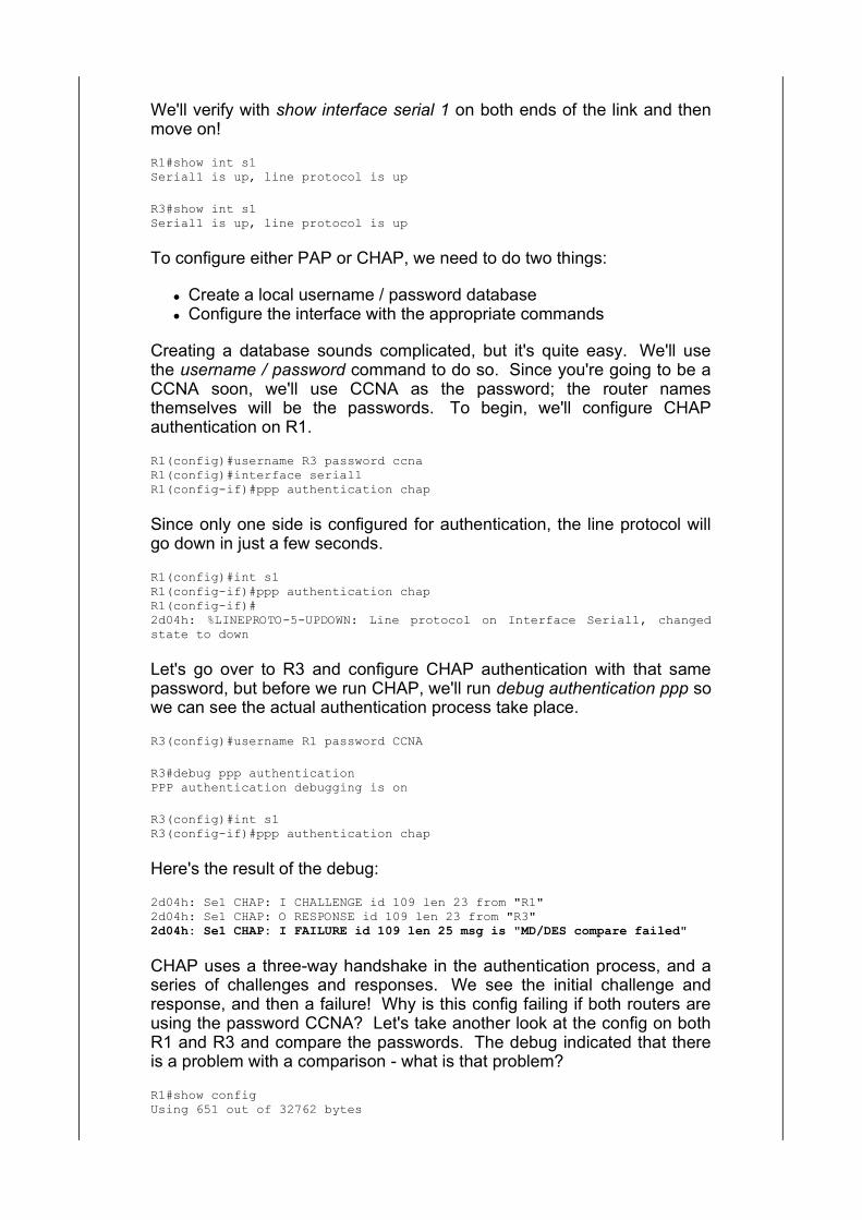
R3(config-if)#ppp authentication pap chap
If R3's remote partner is not using PAP, R3 will then send CHAPmessages.
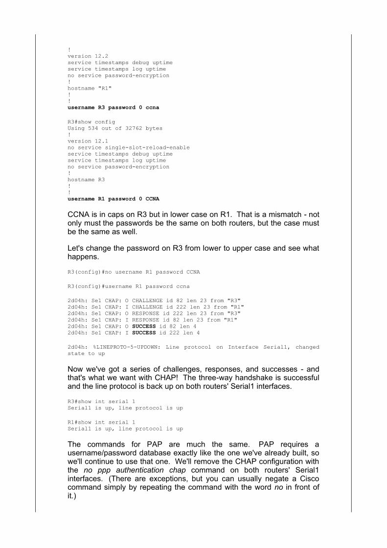
If R1 does respond to the PAP messages and the result is failedauthentication, R3 will *not* try CHAP.
Why You Should Choose CHAP Over PAP
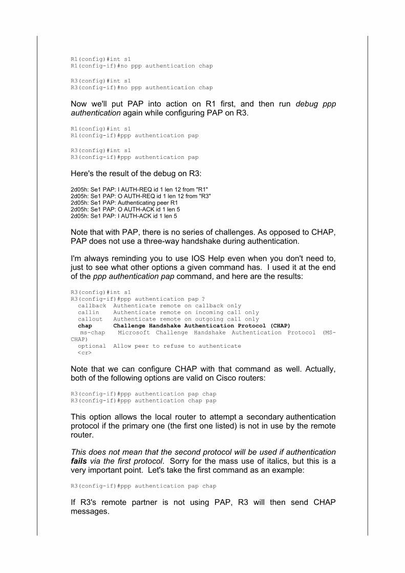
A natural question at this point is "If the configuration's about the same,why use one over the other?" The drawback with PAP is that the boththe username and password are sent over the WAN link in clear text. If apotential network intruder intercepts that information, they're going tobecome an actual network intruder in no time, since they can easily readthe username and password.
CHAP never sends the password over the WAN link. Instead, CHAP runsa mathematical formula against the password, resulting in a hash value. It is this hash value that is passed over the link. If a potential intruderdoes intercept this packet and takes a look at that hash, he's unlikely tocome up with the password from that hash.
Multilink PPP, Compression, And PPP Callback
Multilink PPP (MPPP) allows us to bundle multiple physical WAN linksinto one logical link. There are different reasons for doing this and theygenerally depend on the network topology, but the main reason I've usedit over ISDN links is to allow the data packets to be broken up intofragments. In turn, this fragmentation allows for greater load balancing,where each of the physical links will carry a similar load rather than havingone link carry most of the load.
MPPP is enabled with the interface-level command ppp multilink.
R3(config-if)#ppp multilink
ISDN is no longer on the CCNA exam, so we will not go through a fullmultilink configuration over ISDN. PPP is often found on analog circuitssuch as ISDN, generally supporting either PAP or CHAP.
PPP also allows us to enable one of two compression techniques, Stackeror Predictor. Both are enabled with the interface-level commandcompress. The differences between the two are far beyond the scope ofthe CCNA exam, but if you'd like to read more, search Cisco's website foreither.
R3(config-if)#compress ? predictor predictor compression type stac stac compression algorithm
ISDN is no longer on the CCNA exam, but there is an ISDN-related PPPfeature you should know about, since it's still somewhat popular on ISDNnetworks. PPP callback gives our router the ability to accept a phone callfrom a remote user, authenticate that user, and then hang up on them andthen call them back.
You're probably thinking "Why would I want the router to hang up on theuser and then call them back?" Great question! The answer is .... money!
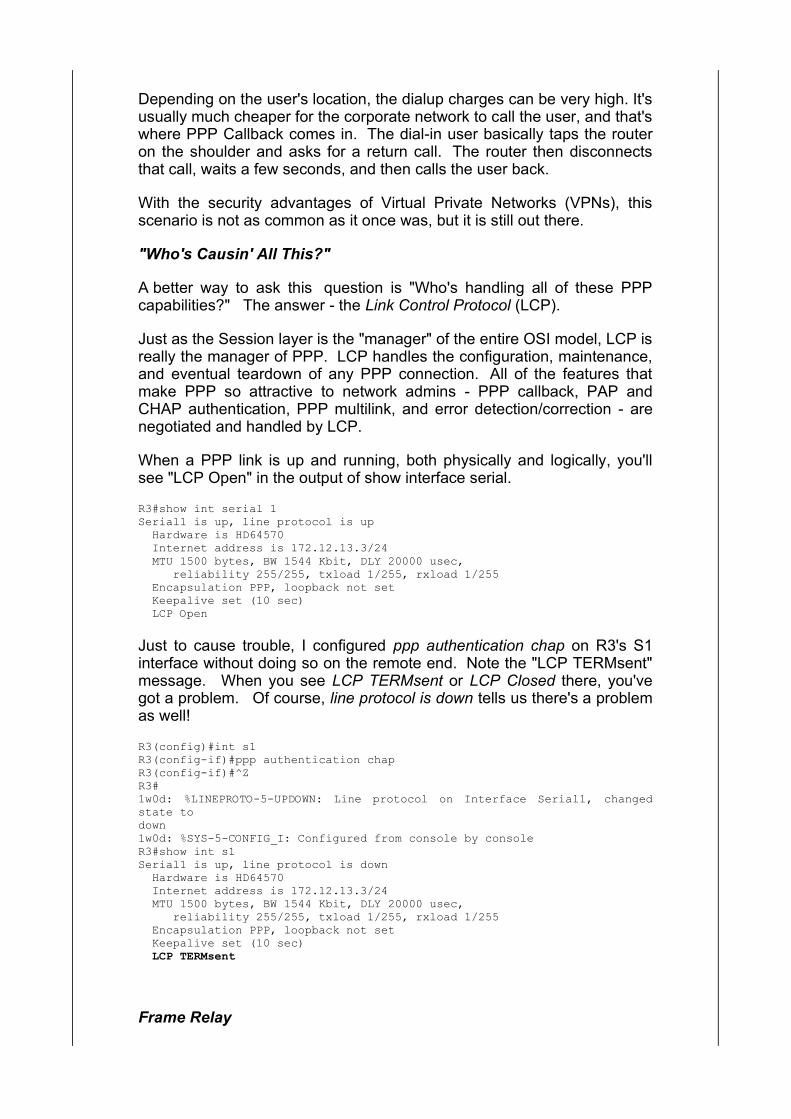
Depending on the user's location, the dialup charges can be very high. It'susually much cheaper for the corporate network to call the user, and that'swhere PPP Callback comes in. The dial-in user basically taps the routeron the shoulder and asks for a return call. The router then disconnectsthat call, waits a few seconds, and then calls the user back.
With the security advantages of Virtual Private Networks (VPNs), thisscenario is not as common as it once was, but it is still out there.
"Who's Causin' All This?"
A better way to ask this question is "Who's handling all of these PPPcapabilities?" The answer - the Link Control Protocol (LCP).
Just as the Session layer is the "manager" of the entire OSI model, LCP isreally the manager of PPP. LCP handles the configuration, maintenance,and eventual teardown of any PPP connection. All of the features thatmake PPP so attractive to network admins - PPP callback, PAP andCHAP authentication, PPP multilink, and error detection/correction - arenegotiated and handled by LCP.
When a PPP link is up and running, both physically and logically, you'llsee "LCP Open" in the output of show interface serial.
R3#show int serial 1Serial1 is up, line protocol is up Hardware is HD64570 Internet address is 172.12.13.3/24 MTU 1500 bytes, BW 1544 Kbit, DLY 20000 usec, reliability 255/255, txload 1/255, rxload 1/255 Encapsulation PPP, loopback not set Keepalive set (10 sec) LCP Open
Just to cause trouble, I configured ppp authentication chap on R3's S1interface without doing so on the remote end. Note the "LCP TERMsent"message. When you see LCP TERMsent or LCP Closed there, you'vegot a problem. Of course, line protocol is down tells us there's a problemas well!
R3(config)#int s1R3(config-if)#ppp authentication chapR3(config-if)#^ZR3#1w0d: %LINEPROTO-5-UPDOWN: Line protocol on Interface Serial1, changedstate todown1w0d: %SYS-5-CONFIG_I: Configured from console by consoleR3#show int s1Serial1 is up, line protocol is down Hardware is HD64570 Internet address is 172.12.13.3/24 MTU 1500 bytes, BW 1544 Kbit, DLY 20000 usec, reliability 255/255, txload 1/255, rxload 1/255 Encapsulation PPP, loopback not set Keepalive set (10 sec) LCP TERMsent
Frame Relay
Frame Relay's got three things going for it that endears it to networkadmins:
it's cheap ("cost-effective", "requires less investment", or whateversales department catchphrase you want to use)
it's reliable it's cheap and reliable (see above)
It also happens to be very prevalent in today's WANs, so it's a good ideato know about it for working with real-world production networks and yourCCENT and CCNA exams!
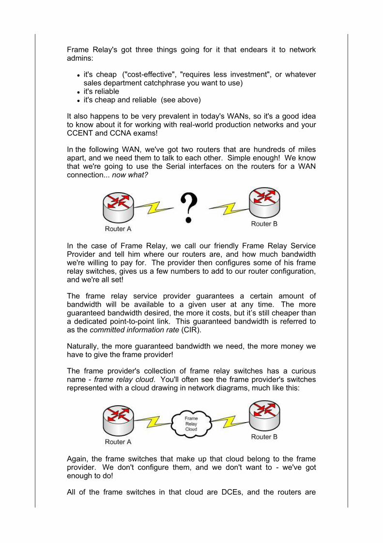
In the following WAN, we've got two routers that are hundreds of milesapart, and we need them to talk to each other. Simple enough! We knowthat we're going to use the Serial interfaces on the routers for a WANconnection... now what?
In the case of Frame Relay, we call our friendly Frame Relay ServiceProvider and tell him where our routers are, and how much bandwidthwe're willing to pay for. The provider then configures some of his framerelay switches, gives us a few numbers to add to our router configuration,and we're all set!
The frame relay service provider guarantees a certain amount ofbandwidth will be available to a given user at any time. The moreguaranteed bandwidth desired, the more it costs, but it’s still cheaper thana dedicated point-to-point link. This guaranteed bandwidth is referred toas the committed information rate (CIR).
Naturally, the more guaranteed bandwidth we need, the more money wehave to give the frame provider!
The frame provider's collection of frame relay switches has a curiousname - frame relay cloud. You'll often see the frame provider's switchesrepresented with a cloud drawing in network diagrams, much like this:
Again, the frame switches that make up that cloud belong to the frameprovider. We don't configure them, and we don't want to - we've gotenough to do!
All of the frame switches in that cloud are DCEs, and the routers are
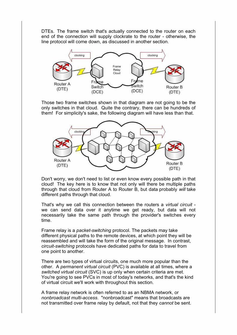
DTEs. The frame switch that's actually connected to the router on eachend of the connection will supply clockrate to the router - otherwise, theline protocol will come down, as discussed in another section.
Those two frame switches shown in that diagram are not going to be theonly switches in that cloud. Quite the contrary, there can be hundreds ofthem! For simplicity's sake, the following diagram will have less than that.
Don't worry, we don't need to list or even know every possible path in thatcloud! The key here is to know that not only will there be multiple pathsthrough that cloud from Router A to Router B, but data probably will takedifferent paths through that cloud.
That's why we call this connection between the routers a virtual circuit -we can send data over it anytime we get ready, but data will notnecessarily take the same path through the provider's switches everytime.
Frame relay is a packet-switching protocol. The packets may takedifferent physical paths to the remote devices, at which point they will bereassembled and will take the form of the original message. In contrast,circuit-switching protocols have dedicated paths for data to travel fromone point to another.
There are two types of virtual circuits, one much more popular than theother. A permanent virtual circuit (PVC) is available at all times, where aswitched virtual circuit (SVC) is up only when certain criteria are met. You're going to see PVCs in most of today's networks, and that's the kindof virtual circuit we'll work with throughout this section.
A frame relay network is often referred to as an NBMA network, ornonbroadcast multi-access. "nonbroadcast" means that broadcasts arenot transmitted over frame relay by default, not that they cannot be sent.
"multiaccess" means that the frame relay network will be shared bymultiple devices.
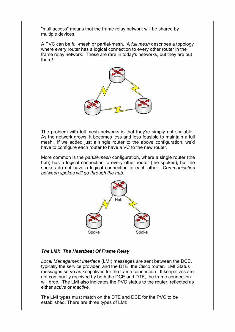
A PVC can be full-mesh or partial-mesh. A full mesh describes a topologywhere every router has a logical connection to every other router in theframe relay network. These are rare in today's networks, but they are outthere!
The problem with full-mesh networks is that they're simply not scalable. As the network grows, it becomes less and less feasible to maintain a fullmesh. If we added just a single router to the above configuration, we'dhave to configure each router to have a VC to the new router.
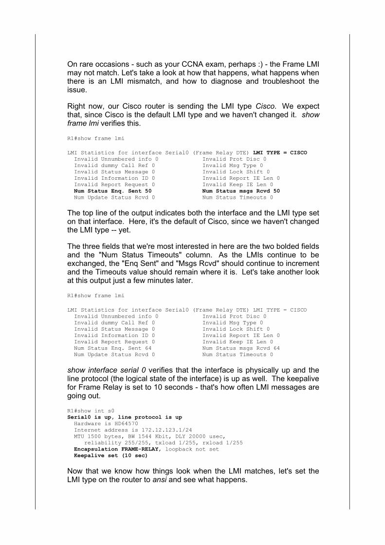
More common is the partial-mesh configuration, where a single router (thehub) has a logical connection to every other router (the spokes), but thespokes do not have a logical connection to each other. Communicationbetween spokes will go through the hub.
The LMI: The Heartbeat Of Frame Relay
Local Management Interface (LMI) messages are sent between the DCE,typically the service provider, and the DTE, the Cisco router. LMI Statusmessages serve as keepalives for the frame connection. If keepalives arenot continually received by both the DCE and DTE, the frame connectionwill drop. The LMI also indicates the PVC status to the router, reflected aseither active or inactive.
The LMI types must match on the DTE and DCE for the PVC to beestablished. There are three types of LMI:

Cisco (the default) ansi q933a
The LMI type can be changed with the frame lmi-type command. Beforedoing anything with the frame relay commands, though, we have toenable frame relay on the interface with the encapsulation frame-relaycommand. Remember, the default encapsulation type on a Cisco Serialinterface is HDLC.
R1(config)#interface serial0R1(config-if)#encapsulation ? atm-dxi ATM-DXI encapsulation frame-relay Frame Relay networks hdlc Serial HDLC synchronous lapb LAPB (X.25 Level 2) ppp Point-to-Point protocol smds Switched Megabit Data Service (SMDS) x25 X.25
R1(config-if)#encapsulation frame-relayR1(config-if)#frame-relay lmi-type ? cisco ansi q933a
We can hardcode the LMI type as shown in that example, and there'sanother way to get the LMI to match with the remote DCE. LMI Autosensehas the router send out an LMI Status message for all three LMI types.
The router then waits for a response for one of those LMI types from theDCE. When the router sees the response to its LMI Autosensemessages, the router will then send only the same LMI type it receivedfrom the DCE.
On rare occasions - such as your CCNA exam, perhaps :) - the Frame LMImay not match. Let's take a look at how that happens, what happens whenthere is an LMI mismatch, and how to diagnose and troubleshoot theissue.
Right now, our Cisco router is sending the LMI type Cisco. We expectthat, since Cisco is the default LMI type and we haven't changed it. showframe lmi verifies this.
R1#show frame lmi
LMI Statistics for interface Serial0 (Frame Relay DTE) LMI TYPE = CISCO Invalid Unnumbered info 0 Invalid Prot Disc 0 Invalid dummy Call Ref 0 Invalid Msg Type 0 Invalid Status Message 0 Invalid Lock Shift 0 Invalid Information ID 0 Invalid Report IE Len 0 Invalid Report Request 0 Invalid Keep IE Len 0 Num Status Enq. Sent 50 Num Status msgs Rcvd 50 Num Update Status Rcvd 0 Num Status Timeouts 0
The top line of the output indicates both the interface and the LMI type seton that interface. Here, it's the default of Cisco, since we haven't changedthe LMI type -- yet.
The three fields that we're most interested in here are the two bolded fieldsand the "Num Status Timeouts" column. As the LMIs continue to beexchanged, the "Enq Sent" and "Msgs Rcvd" should continue to incrementand the Timeouts value should remain where it is. Let's take another lookat this output just a few minutes later.
R1#show frame lmi
LMI Statistics for interface Serial0 (Frame Relay DTE) LMI TYPE = CISCO Invalid Unnumbered info 0 Invalid Prot Disc 0 Invalid dummy Call Ref 0 Invalid Msg Type 0 Invalid Status Message 0 Invalid Lock Shift 0 Invalid Information ID 0 Invalid Report IE Len 0 Invalid Report Request 0 Invalid Keep IE Len 0 Num Status Enq. Sent 64 Num Status msgs Rcvd 64 Num Update Status Rcvd 0 Num Status Timeouts 0
show interface serial 0 verifies that the interface is physically up and theline protocol (the logical state of the interface) is up as well. The keepalivefor Frame Relay is set to 10 seconds - that's how often LMI messages aregoing out.
R1#show int s0Serial0 is up, line protocol is up Hardware is HD64570 Internet address is 172.12.123.1/24 MTU 1500 bytes, BW 1544 Kbit, DLY 20000 usec, reliability 255/255, txload 1/255, rxload 1/255 Encapsulation FRAME-RELAY, loopback not set Keepalive set (10 sec)
Now that we know how things look when the LMI matches, let's set theLMI type on the router to ansi and see what happens.
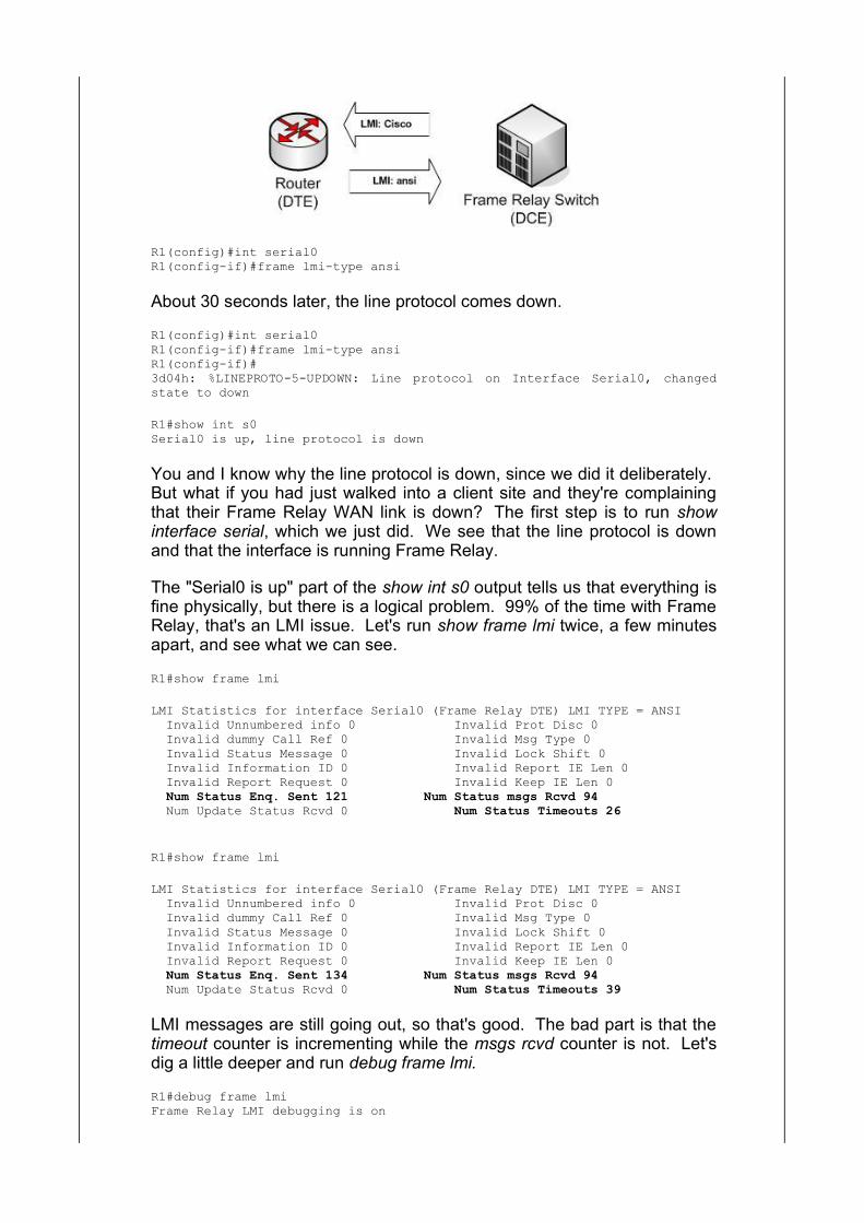
R1(config)#int serial0R1(config-if)#frame lmi-type ansi
About 30 seconds later, the line protocol comes down.
R1(config)#int serial0R1(config-if)#frame lmi-type ansiR1(config-if)#3d04h: %LINEPROTO-5-UPDOWN: Line protocol on Interface Serial0, changedstate to down
R1#show int s0Serial0 is up, line protocol is down
You and I know why the line protocol is down, since we did it deliberately. But what if you had just walked into a client site and they're complainingthat their Frame Relay WAN link is down? The first step is to run showinterface serial, which we just did. We see that the line protocol is downand that the interface is running Frame Relay.
The "Serial0 is up" part of the show int s0 output tells us that everything isfine physically, but there is a logical problem. 99% of the time with FrameRelay, that's an LMI issue. Let's run show frame lmi twice, a few minutesapart, and see what we can see.
R1#show frame lmi
LMI Statistics for interface Serial0 (Frame Relay DTE) LMI TYPE = ANSI Invalid Unnumbered info 0 Invalid Prot Disc 0 Invalid dummy Call Ref 0 Invalid Msg Type 0 Invalid Status Message 0 Invalid Lock Shift 0 Invalid Information ID 0 Invalid Report IE Len 0 Invalid Report Request 0 Invalid Keep IE Len 0 Num Status Enq. Sent 121 Num Status msgs Rcvd 94 Num Update Status Rcvd 0 Num Status Timeouts 26
R1#show frame lmi
LMI Statistics for interface Serial0 (Frame Relay DTE) LMI TYPE = ANSI Invalid Unnumbered info 0 Invalid Prot Disc 0 Invalid dummy Call Ref 0 Invalid Msg Type 0 Invalid Status Message 0 Invalid Lock Shift 0 Invalid Information ID 0 Invalid Report IE Len 0 Invalid Report Request 0 Invalid Keep IE Len 0 Num Status Enq. Sent 134 Num Status msgs Rcvd 94 Num Update Status Rcvd 0 Num Status Timeouts 39
LMI messages are still going out, so that's good. The bad part is that thetimeout counter is incrementing while the msgs rcvd counter is not. Let'sdig a little deeper and run debug frame lmi.
R1#debug frame lmiFrame Relay LMI debugging is on
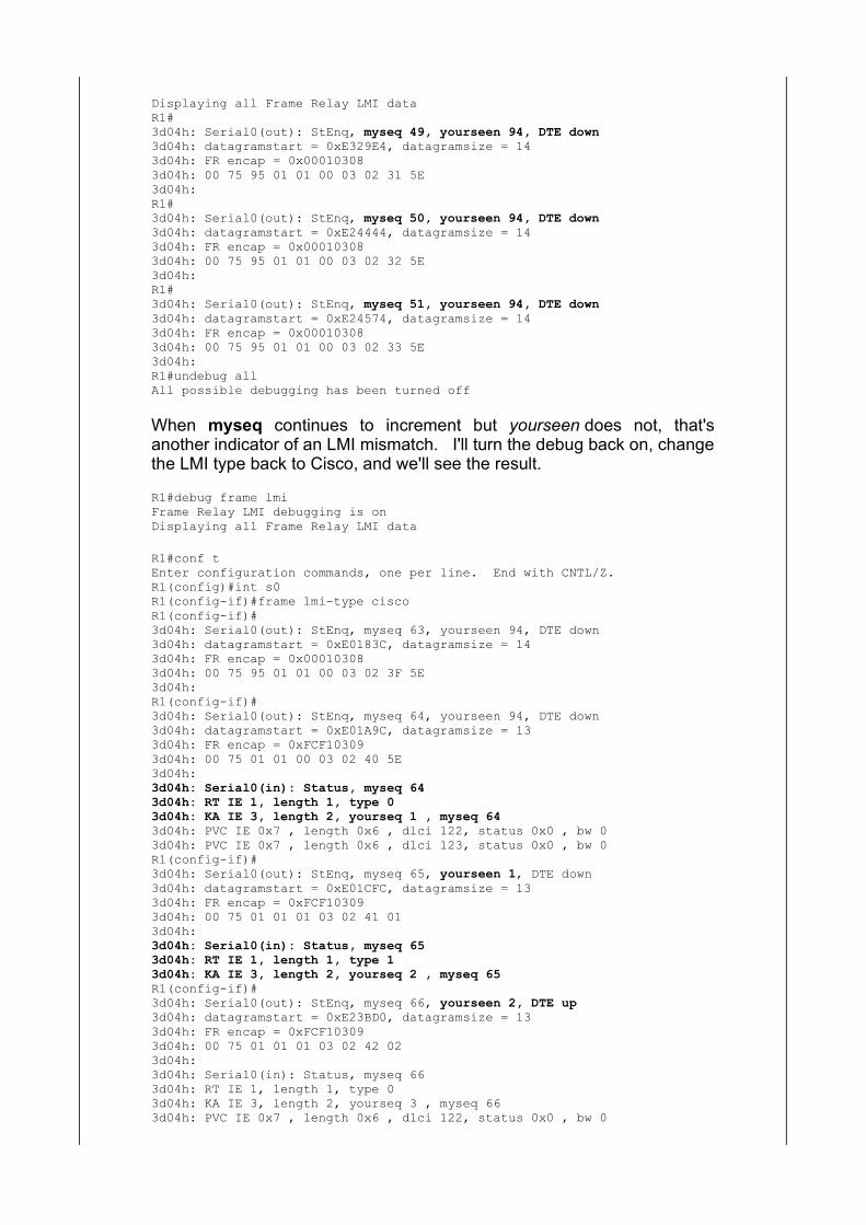
Displaying all Frame Relay LMI dataR1#3d04h: Serial0(out): StEnq, myseq 49, yourseen 94, DTE down3d04h: datagramstart = 0xE329E4, datagramsize = 143d04h: FR encap = 0x000103083d04h: 00 75 95 01 01 00 03 02 31 5E3d04h:R1#3d04h: Serial0(out): StEnq, myseq 50, yourseen 94, DTE down3d04h: datagramstart = 0xE24444, datagramsize = 143d04h: FR encap = 0x000103083d04h: 00 75 95 01 01 00 03 02 32 5E3d04h:R1#3d04h: Serial0(out): StEnq, myseq 51, yourseen 94, DTE down3d04h: datagramstart = 0xE24574, datagramsize = 143d04h: FR encap = 0x000103083d04h: 00 75 95 01 01 00 03 02 33 5E3d04h:R1#undebug allAll possible debugging has been turned off
When myseq continues to increment but yourseen does not, that'sanother indicator of an LMI mismatch. I'll turn the debug back on, changethe LMI type back to Cisco, and we'll see the result.
R1#debug frame lmiFrame Relay LMI debugging is onDisplaying all Frame Relay LMI data
R1#conf tEnter configuration commands, one per line. End with CNTL/Z.R1(config)#int s0R1(config-if)#frame lmi-type ciscoR1(config-if)#3d04h: Serial0(out): StEnq, myseq 63, yourseen 94, DTE down3d04h: datagramstart = 0xE0183C, datagramsize = 143d04h: FR encap = 0x000103083d04h: 00 75 95 01 01 00 03 02 3F 5E3d04h:R1(config-if)#3d04h: Serial0(out): StEnq, myseq 64, yourseen 94, DTE down3d04h: datagramstart = 0xE01A9C, datagramsize = 133d04h: FR encap = 0xFCF103093d04h: 00 75 01 01 00 03 02 40 5E3d04h:3d04h: Serial0(in): Status, myseq 643d04h: RT IE 1, length 1, type 03d04h: KA IE 3, length 2, yourseq 1 , myseq 643d04h: PVC IE 0x7 , length 0x6 , dlci 122, status 0x0 , bw 03d04h: PVC IE 0x7 , length 0x6 , dlci 123, status 0x0 , bw 0R1(config-if)#3d04h: Serial0(out): StEnq, myseq 65, yourseen 1, DTE down3d04h: datagramstart = 0xE01CFC, datagramsize = 133d04h: FR encap = 0xFCF103093d04h: 00 75 01 01 01 03 02 41 013d04h:3d04h: Serial0(in): Status, myseq 653d04h: RT IE 1, length 1, type 13d04h: KA IE 3, length 2, yourseq 2 , myseq 65R1(config-if)#3d04h: Serial0(out): StEnq, myseq 66, yourseen 2, DTE up3d04h: datagramstart = 0xE23BD0, datagramsize = 133d04h: FR encap = 0xFCF103093d04h: 00 75 01 01 01 03 02 42 023d04h:3d04h: Serial0(in): Status, myseq 663d04h: RT IE 1, length 1, type 03d04h: KA IE 3, length 2, yourseq 3 , myseq 663d04h: PVC IE 0x7 , length 0x6 , dlci 122, status 0x0 , bw 0
3d04h: PVC IE 0x7 , length 0x6 , dlci 123, status 0x0 , bw 03d04h: %LINEPROTO-5-UPDOWN: Line protocol on Interface Serial0, changedstate t upR1(config-if)#^ZR1#3d04h: Serial0(out): StEnq, myseq 67, yourseen 3, DTE up3d04h: datagramstart = 0xE23D00, datagramsize = 133d04h: FR encap = 0xFCF103093d04h: 00 75 01 01 01 03 02 43 033d04h:3d04h: Serial0(in): Status, myseq 673d04h: RT IE 1, length 1, type 13d04h: KA IE 3, length 2, yourseq 4 , myseq 67
R1#undebug allAll possible debugging has been turned off
As yourseq and yourseen begin to increment, the line protocol comesback up. Once you see that, you should be fine, but always stick aroundfor a minute or so and make sure the line protocol stays up. Once you'redone, always do two things....
Verify the line protocol is up with show interface serial. Note that you cansee other information relating to the LMI in this output.
R1#show int s0Serial0 is up, line protocol is up Hardware is HD64570 Internet address is 172.12.123.1/24 MTU 1500 bytes, BW 1544 Kbit, DLY 20000 usec, reliability 255/255, txload 1/255, rxload 1/255 Encapsulation FRAME-RELAY, loopback not set Keepalive set (10 sec) LMI enq sent 180, LMI stat recvd 114, LMI upd recvd 0, DTE LMI up LMI enq recvd 0, LMI stat sent 0, LMI upd sent 0 LMI DLCI 1023 LMI type is CISCO frame relay DTE
And before you leave the client site... turn off your debugs, eitherindividually or with the undebug all command.
R1#undebug allAll possible debugging has been turned off
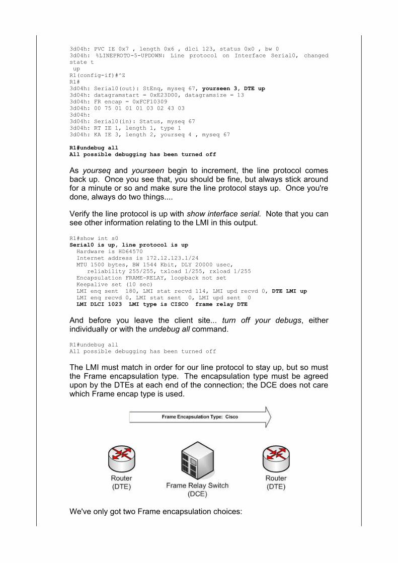
The LMI must match in order for our line protocol to stay up, but so mustthe Frame encapsulation type. The encapsulation type must be agreedupon by the DTEs at each end of the connection; the DCE does not carewhich Frame encap type is used.
We've only got two Frame encapsulation choices:

Cisco (the default - detecting a pattern here?) IETF (the industry standard)
Interestingly enough, IOS Help does not mention the Cisco default, onlythe option to change the Frame encap to IETF.
R1(config)#int s0R1(config-if)#encap frame ? ietf Use RFC1490/RFC2427 encapsulation <cr>
DLCIs, Frame Maps, and Inverse ARP
Frame Relay VCs use Data-Link Connection Identifiers (DLCIs) as theiraddresses. A DLCI is simply a Frame Relay Layer 2 address, but it's a bitdifferent from other addresses in that they can be reused from one routerto another.
The reason that DLCIs have local significance only is that DLCI numbersare not advertised to other routers, and other routers can use the sameDLCI numbers without causing connectivity issues.
I know this sounds odd, but it will become clearer after we work throughsome examples of Frame Relay mapping, both dynamic and static.
If you've read any of my other study guides or any of the tutorials on thewebsite, you know I'm all for the letting the routers and switches do theirwork dynamically whenever possible. Not only does that save ourvaluable time as network admins, but using dynamic address learningmethods is usually much more effective than static methods.
During our switching discussion, we learned that we've got a choicebetween letting the switches learn MAC addresses dynamically andconfiguring them statically. We also learned it's much more effective toallow dynamic learning rather than using static configs.
As you'll see during our routing discussions throughout this course, it'salso more effective to use dynamic routing protocols rather than a hugecollection of static routes.
But.... and you knew that was coming ... there are times when staticconfigurations are actually preferred over dynamic learning, and that'svery true of Frame Relay mapping statements.
Frame map statements are the core of Frame's operation, and we've gotto have them. We've got two choices when it comes to Frame mapping:
Use Inverse ARP (iARP) to enable dynamic mapping Use static frame map statements to create a static configuration
I'm quite sure you'll be asked about both of these on your CCNA exam, sowe'll discuss them both right now. Inverse ARP is easily enabled -actually, it's enabled by default - so we won't spend a great deal of timewith that protocol. Don't ignore it, though!
Frame map statements are a little more complex, and you should payparticular attention to the syntax of the command. Having said that, let'sjump in and take a look at our frame mapping options.
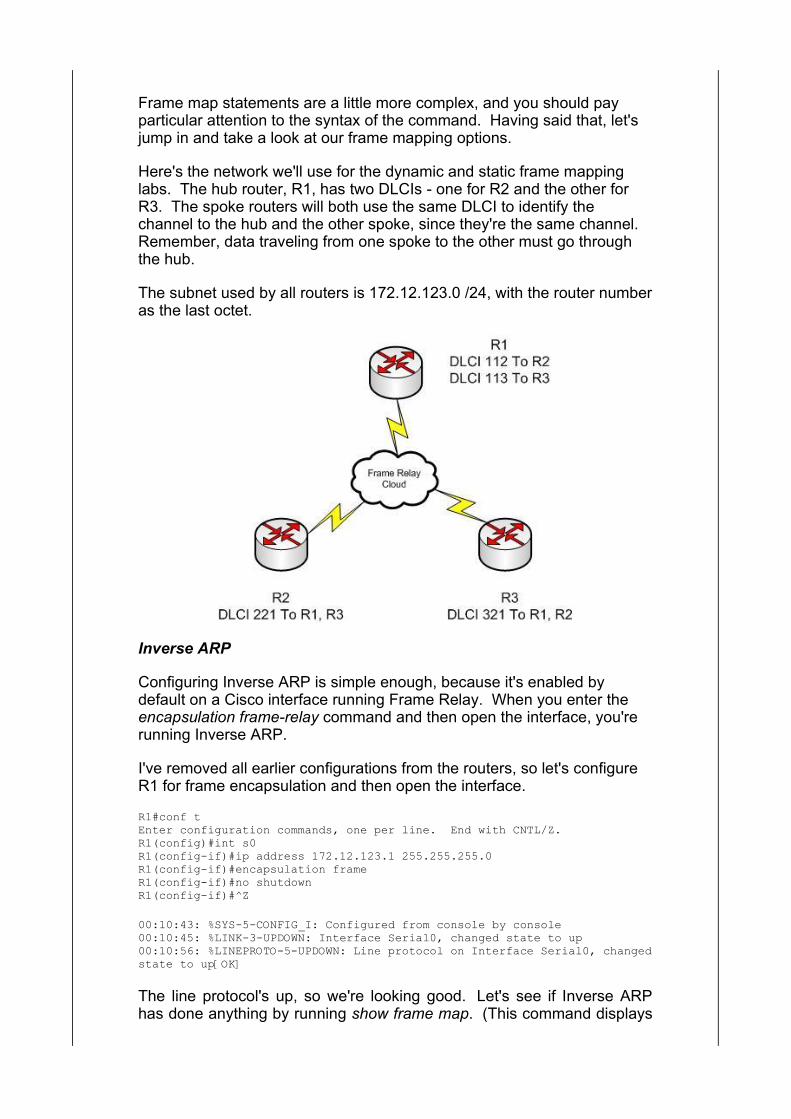
Here's the network we'll use for the dynamic and static frame mappinglabs. The hub router, R1, has two DLCIs - one for R2 and the other forR3. The spoke routers will both use the same DLCI to identify thechannel to the hub and the other spoke, since they're the same channel. Remember, data traveling from one spoke to the other must go throughthe hub.
The subnet used by all routers is 172.12.123.0 /24, with the router numberas the last octet.
Inverse ARP
Configuring Inverse ARP is simple enough, because it's enabled bydefault on a Cisco interface running Frame Relay. When you enter theencapsulation frame-relay command and then open the interface, you'rerunning Inverse ARP.
I've removed all earlier configurations from the routers, so let's configureR1 for frame encapsulation and then open the interface.
R1#conf tEnter configuration commands, one per line. End with CNTL/Z.R1(config)#int s0R1(config-if)#ip address 172.12.123.1 255.255.255.0R1(config-if)#encapsulation frameR1(config-if)#no shutdownR1(config-if)#^Z
00:10:43: %SYS-5-CONFIG_I: Configured from console by console00:10:45: %LINK-3-UPDOWN: Interface Serial0, changed state to up00:10:56: %LINEPROTO-5-UPDOWN: Line protocol on Interface Serial0, changedstate to up[OK]
The line protocol's up, so we're looking good. Let's see if Inverse ARPhas done anything by running show frame map. (This command displays
both static and dynamic mappings.)
R1#show frame mapSerial0 (up): ip 0.0.0.0 dlci 123(0x7B,0x1CB0) broadcast, CISCO, status defined, inactiveSerial0 (up): ip 0.0.0.0 dlci 122(0x7A,0x1CA0) broadcast, CISCO, status defined, inactive
This mapping to "0.0.0.0" occasionally happens with Inverse ARP. Thoseare the only mappings we have right now, and they're going to be the onlyones we do get in this particular situation.
Inverse ARP is one of those protocols that sound great in theory, but don'talways work in the real world. Most Frame Relay configurations don't useInverse ARP, using the more dependable static mappings instead.
It's a bad idea to mix static and dynamic mappings, so if you're going touse static mappings, turn Inverse ARP off with the no frame-relay inverse-arp command.
R1(config)#int s0R1(config-if)#no frame-relay inverse-arp
If you turn it off before opening the interface, you will not get thosemappings to 0.0.0.0. Those mappings really don't hurt anything, butturning Inverse ARP off after opening the interface will not get rid of them. I've always needed a reload to get rid of those annoying mappings.
If you decide to turn it back on, use the frame-relay inverse-arp command.
R1(config)#int s0R1(config-if)#frame inverse-arp
Frame Map Statements
It won't surprise you to learn that we'll use the frame map command tocreate frame maps, but you must be careful with the syntax of thiscommand. That goes for the exam room and working with the real thing!
Let's take another look at the network.
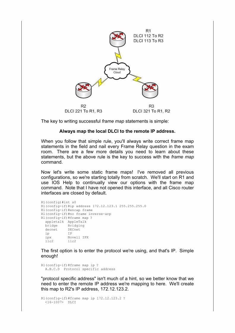
The key to writing successful frame map statements is simple:
Always map the local DLCI to the remote IP address.
When you follow that simple rule, you'll always write correct frame mapstatements in the field and nail every Frame Relay question in the examroom. There are a few more details you need to learn about thesestatements, but the above rule is the key to success with the frame mapcommand.
Now let's write some static frame maps! I've removed all previousconfigurations, so we're starting totally from scratch. We'll start on R1 anduse IOS Help to continually view our options with the frame mapcommand. Note that I have not opened this interface, and all Cisco routerinterfaces are closed by default.
R1(config)#int s0R1(config-if)#ip address 172.12.123.1 255.255.255.0R1(config-if)#encap frameR1(config-if)#no frame inverse-arpR1(config-if)#frame map ? appletalk AppleTalk bridge Bridging decnet DECnet ip IP ipx Novell IPX llc2 llc2
The first option is to enter the protocol we're using, and that's IP. Simpleenough!
R1(config-if)#frame map ip ? A.B.C.D Protocol specific address
"protocol specific address" isn't much of a hint, so we better know that weneed to enter the remote IP address we're mapping to here. We'll createthis map to R2's IP address, 172.12.123.2.
R1(config-if)#frame map ip 172.12.123.2 ? <16-1007> DLCI
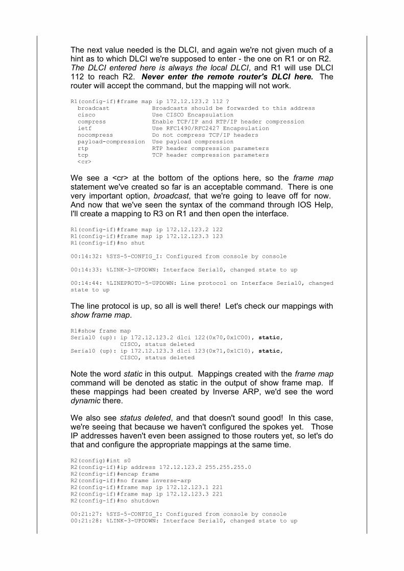
The next value needed is the DLCI, and again we're not given much of ahint as to which DLCI we're supposed to enter - the one on R1 or on R2. The DLCI entered here is always the local DLCI, and R1 will use DLCI112 to reach R2. Never enter the remote router's DLCI here. Therouter will accept the command, but the mapping will not work.
R1(config-if)#frame map ip 172.12.123.2 112 ? broadcast Broadcasts should be forwarded to this address cisco Use CISCO Encapsulation compress Enable TCP/IP and RTP/IP header compression ietf Use RFC1490/RFC2427 Encapsulation nocompress Do not compress TCP/IP headers payload-compression Use payload compression rtp RTP header compression parameters tcp TCP header compression parameters <cr>
We see a <cr> at the bottom of the options here, so the frame mapstatement we've created so far is an acceptable command. There is onevery important option, broadcast, that we're going to leave off for now. And now that we've seen the syntax of the command through IOS Help,I'll create a mapping to R3 on R1 and then open the interface.
R1(config-if)#frame map ip 172.12.123.2 122R1(config-if)#frame map ip 172.12.123.3 123R1(config-if)#no shut
00:14:32: %SYS-5-CONFIG_I: Configured from console by console
00:14:33: %LINK-3-UPDOWN: Interface Serial0, changed state to up
00:14:44: %LINEPROTO-5-UPDOWN: Line protocol on Interface Serial0, changedstate to up
The line protocol is up, so all is well there! Let's check our mappings withshow frame map.
R1#show frame map Serial0 (up): ip 172.12.123.2 dlci 122(0x70,0x1C00), static, CISCO, status deletedSerial0 (up): ip 172.12.123.3 dlci 123(0x71,0x1C10), static, CISCO, status deleted
Note the word static in this output. Mappings created with the frame mapcommand will be denoted as static in the output of show frame map. Ifthese mappings had been created by Inverse ARP, we'd see the worddynamic there.
We also see status deleted, and that doesn't sound good! In this case,we're seeing that because we haven't configured the spokes yet. ThoseIP addresses haven't even been assigned to those routers yet, so let's dothat and configure the appropriate mappings at the same time.
R2(config)#int s0R2(config-if)#ip address 172.12.123.2 255.255.255.0R2(config-if)#encap frameR2(config-if)#no frame inverse-arpR2(config-if)#frame map ip 172.12.123.1 221R2(config-if)#frame map ip 172.12.123.3 221R2(config-if)#no shutdown
00:21:27: %SYS-5-CONFIG_I: Configured from console by console00:21:28: %LINK-3-UPDOWN: Interface Serial0, changed state to up

00:21:38: %FR-5-DLCICHANGE: Interface Serial0 - DLCI 221 state changed toACTIVE00:21:39: %LINEPROTO-5-UPDOWN: Line protocol on Interface Serial0, changedstate to up
There's a message about DLCI 221 changing to ACTIVE, so let's runshow frame map and see what's going on.
R2#show frame mapSerial0 (up): ip 172.12.123.1 dlci 221(0xDD,0x34D0), static, CISCO, status defined, activeSerial0 (up): ip 172.12.123.3 dlci 221(0xDD,0x34D0), static, CISCO, status defined, active
Looks good! Let's configure R3 and then see where things stand.
R3(config)#int serial0R3(config-if)#ip address 172.12.123.3 255.255.255.0R3(config-if)#encap frameR3(config-if)#no frame inverR3(config-if)#frame map ip 172.12.123.1 321R3(config-if)#frame map ip 172.12.123.2 321R3(config-if)#no shutdown
00:24:38: %LINEPROTO-5-UPDOWN: Line protocol on Interface Serial0, changedstate to up
R3#show frame mapSerial0 (up): ip 172.12.123.1 dlci 321(0x141,0x5010), static, CISCO, status defined, activeSerial0 (up): ip 172.12.123.2 dlci 321(0x141,0x5010), static, CISCO, status defined, active
The mappings on both spokes are showing as active. Let's check the hub!
R1#show frame mapSerial0 (up): ip 172.12.123.2 dlci 122(0x7A,0x1CA0), static, CISCO, status defined, activeSerial0 (up): ip 172.12.123.3 dlci 123(0x7B,0x1CB0), static, CISCO, status defined, active
Each router can now ping the other, and we have basic IP connectivity.
R1#ping 172.12.123.2
Type escape sequence to abort.Sending 5, 100-byte ICMP Echos to 172.12.123.2, timeout is 2 seconds:!!!!!Success rate is 100 percent (5/5), round-trip min/avg/max = 68/68/68 ms
R1#ping 172.12.123.3
Type escape sequence to abort.Sending 5, 100-byte ICMP Echos to 172.12.123.3, timeout is 2 seconds:!!!!!Success rate is 100 percent (5/5), round-trip min/avg/max = 68/70/72 ms
R2#ping 172.12.123.1
Type escape sequence to abort.Sending 5, 100-byte ICMP Echos to 172.12.123.1, timeout is 2 seconds:!!!!!Success rate is 100 percent (5/5), round-trip min/avg/max = 68/68/68 ms
R2#ping 172.12.123.3
Type escape sequence to abort.Sending 5, 100-byte ICMP Echos to 172.12.123.3, timeout is 2 seconds:!!!!!Success rate is 100 percent (5/5), round-trip min/avg/max = 132/134/144 ms
R3#ping 172.12.123.1
Type escape sequence to abort.Sending 5, 100-byte ICMP Echos to 172.12.123.1, timeout is 2 seconds:!!!!!Success rate is 100 percent (5/5), round-trip min/avg/max = 68/68/68 msR3#ping 172.12.123.2
Type escape sequence to abort.Sending 5, 100-byte ICMP Echos to 172.12.123.2, timeout is 2 seconds:!!!!!Success rate is 100 percent (5/5), round-trip min/avg/max = 128/131/132 ms
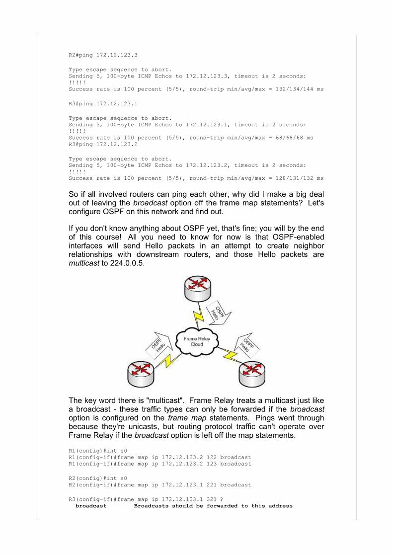
So if all involved routers can ping each other, why did I make a big dealout of leaving the broadcast option off the frame map statements? Let'sconfigure OSPF on this network and find out.
If you don't know anything about OSPF yet, that's fine; you will by the endof this course! All you need to know for now is that OSPF-enabledinterfaces will send Hello packets in an attempt to create neighborrelationships with downstream routers, and those Hello packets aremulticast to 224.0.0.5.
The key word there is "multicast". Frame Relay treats a multicast just likea broadcast - these traffic types can only be forwarded if the broadcastoption is configured on the frame map statements. Pings went throughbecause they're unicasts, but routing protocol traffic can't operate overFrame Relay if the broadcast option is left off the map statements.
R1(config)#int s0R1(config-if)#frame map ip 172.12.123.2 122 broadcastR1(config-if)#frame map ip 172.12.123.2 123 broadcast
R2(config)#int s0R2(config-if)#frame map ip 172.12.123.1 221 broadcast
R3(config-if)#frame map ip 172.12.123.1 321 ? broadcast Broadcasts should be forwarded to this address
cisco Use CISCO Encapsulation compress Enable TCP/IP and RTP/IP header compression ietf Use RFC1490/RFC2427 Encapsulation nocompress Do not compress TCP/IP headers payload-compression Use payload compression rtp RTP header compression parameters tcp TCP header compression parameters <cr>
R3(config-if)#frame map ip 172.12.123.1 321 broadcast
If you're having trouble with routing protocol Hellos or other multicasts andbroadcasts not being received by routers on a Frame Relay network, I canpractically guarantee you that the problem is a missing broadcaststatement.
Note that I didn't rewrite the frame map command on R2 that mappedDLCI 221 to R3, nor did I rewrite the frame map command on R3 thatmapped DLCI 321 to R2. Routers do not forward broadcasts, so it'simpossible for R2 to send a broadcast to R3, and vice versa. It doesn'thurt to put the broadcast option on spoke-to-spoke mappings anyway, andmost networks do just that.
So while this is fine on the spokes....
R2:
interface Serial0 ip address 172.12.123.2 255.255.255.0 encapsulation frame-relay frame-relay map ip 172.12.123.1 221 broadcast frame-relay map ip 172.12.123.3 221 no frame-relay inverse-arp
R3:
interface Serial0 ip address 172.12.123.3 255.255.255.0 encapsulation frame-relay frame-relay map ip 172.12.123.1 321 broadcast frame-relay map ip 172.12.123.2 321 no frame-relay inverse-arp
.... you'll usually see the broadcast statement on the end of all frame mapstatements. Just make sure they're on the map statements referring to thehub's IP address, and if you're having trouble getting routing updates and /or routing protocol keepalives across your WAN, check this first!
Subinterfaces And Frame Relay
In the previous examples, we've used physical Serial interfaces for ourFrame Relay networks. Using a physical Serial interface can lead to somerouting complications, particularly on the hub router. One of thosecomplications is Split Horizon.
Split Horizon is a distance-vector routing protocol behavior. If we'rerunning OSPF on our network, there's no problem. On RIP networks, splithorizon can be a problem, as illustrated by the following network topology.
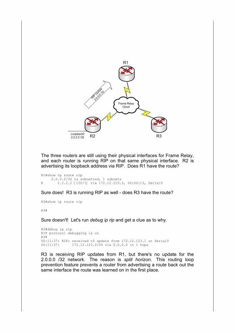
The three routers are still using their physical interfaces for Frame Relay,and each router is running RIP on that same physical interface. R2 isadvertising its loopback address via RIP. Does R1 have the route?
R1#show ip route rip 2.0.0.0/32 is subnetted, 1 subnetsR 2.2.2.2 [120/1] via 172.12.123.3, 00:00:13, Serial0
Sure does! R3 is running RIP as well - does R3 have the route?
R3#show ip route rip
R3#
Sure doesn't! Let's run debug ip rip and get a clue as to why.
R3#debug ip ripRIP protocol debugging is onR3#00:11:37: RIP: received v2 update from 172.12.123.1 on Serial000:11:37: 172.12.123.0/24 via 0.0.0.0 in 1 hops
R3 is receiving RIP updates from R1, but there's no update for the2.0.0.0 /32 network. The reason is split horizon. This routing loopprevention feature prevents a router from advertising a route back out thesame interface the route was learned on in the first place.
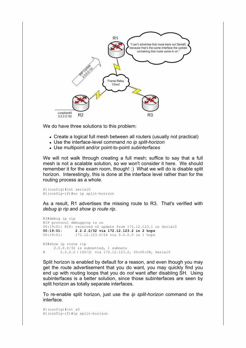
We do have three solutions to this problem:
Create a logical full mesh between all routers (usually not practical) Use the interface-level command no ip split-horizon Use multipoint and/or point-to-point subinterfaces
We will not walk through creating a full mesh; suffice to say that a fullmesh is not a scalable solution, so we won't consider it here. We shouldremember it for the exam room, though! :) What we will do is disable splithorizon. Interestingly, this is done at the interface level rather than for therouting process as a whole.
R1(config)#int serial0R1(config-if)#no ip split-horizon
As a result, R1 advertises the missing route to R3. That's verified withdebug ip rip and show ip route rip.
R3#debug ip ripRIP protocol debugging is on00:19:01: RIP: received v2 update from 172.12.123.1 on Serial000:19:01: 2.2.2.2/32 via 172.12.123.2 in 2 hops00:19:01: 172.12.123.0/24 via 0.0.0.0 in 1 hops
R3#show ip route rip 2.0.0.0/32 is subnetted, 1 subnetsR 2.2.2.2 [120/2] via 172.12.123.2, 00:00:08, Serial0
Split horizon is enabled by default for a reason, and even though you mayget the route advertisement that you do want, you may quickly find youend up with routing loops that you do not want after disabling SH. Usingsubinterfaces is a better solution, since those subinterfaces are seen bysplit horizon as totally separate interfaces.
To re-enable split horizon, just use the ip split-horizon command on theinterface.
R1(config)#int s0R1(config-if)#ip split-horizon
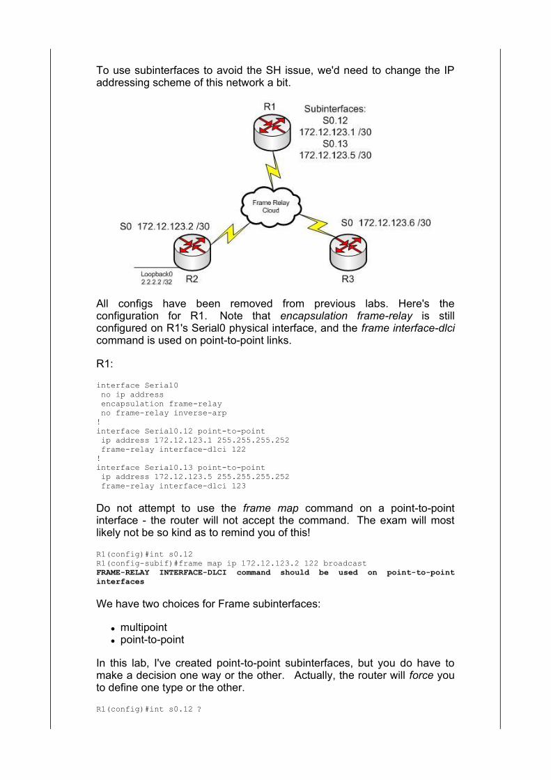
To use subinterfaces to avoid the SH issue, we'd need to change the IPaddressing scheme of this network a bit.
All configs have been removed from previous labs. Here's theconfiguration for R1. Note that encapsulation frame-relay is stillconfigured on R1's Serial0 physical interface, and the frame interface-dlcicommand is used on point-to-point links.
R1:
interface Serial0 no ip address encapsulation frame-relay no frame-relay inverse-arp!interface Serial0.12 point-to-point ip address 172.12.123.1 255.255.255.252 frame-relay interface-dlci 122!interface Serial0.13 point-to-point ip address 172.12.123.5 255.255.255.252 frame-relay interface-dlci 123
Do not attempt to use the frame map command on a point-to-pointinterface - the router will not accept the command. The exam will mostlikely not be so kind as to remind you of this!
R1(config)#int s0.12R1(config-subif)#frame map ip 172.12.123.2 122 broadcastFRAME-RELAY INTERFACE-DLCI command should be used on point-to-pointinterfaces
We have two choices for Frame subinterfaces:
multipoint point-to-point
In this lab, I've created point-to-point subinterfaces, but you do have tomake a decision one way or the other. Actually, the router will force youto define one type or the other.
R1(config)#int s0.12 ?
multipoint Treat as a multipoint link point-to-point Treat as a point-to-point link
R1(config)#int s0.12 < no subinterface type specified >% Incomplete command.
R1(config)#interface s0.12 point-to-pointR1(config-subif)#
The configurations on R2 and R3 are much the same, except there are nospoke-to-spoke mappings.
R2:
interface Serial0 ip address 172.12.123.2 255.255.255.252 encapsulation frame-relay frame-relay map ip 172.12.123.1 221 broadcast no frame-relay inverse-arp
R2#show frame mapSerial0 (up): ip 172.12.123.1 dlci 221(0xDD,0x34D0), static, broadcast, CISCO, status defined, active
R3:
interface Serial0 ip address 172.12.123.6 255.255.255.252 encapsulation frame-relay frame-relay map ip 172.12.123.1 321 broadcast no frame-relay inverse-arp
R3#show frame mapSerial0 (up): ip 172.12.123.5 dlci 321(0x141,0x5010), static, broadcast, CISCO, status defined, active
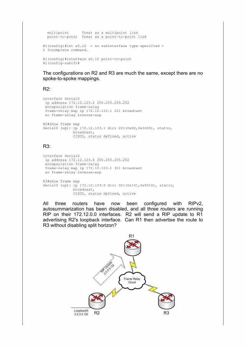
All three routers have now been configured with RIPv2,autosummarization has been disabled, and all three routers are runningRIP on their 172.12.0.0 interfaces. R2 will send a RIP update to R1advertising R2's loopback interface. Can R1 then advertise the route toR3 without disabling split horizon?

R1 has the route and can ping 2.2.2.2, as verified by show ip route rip andping.
R1#show ip route rip 2.0.0.0/32 is subnetted, 1 subnetsR 2.2.2.2 [120/1] via 172.12.123.2, 00:00:05, Serial0.12R1#ping 2.2.2.2
Type escape sequence to abort.Sending 5, 100-byte ICMP Echos to 2.2.2.2, timeout is 2 seconds:!!!!!Success rate is 100 percent (5/5), round-trip min/avg/max = 68/68/68 ms
What about R3? Let's check R3's RIP table and find out!
R3#show ip route rip 2.0.0.0/32 is subnetted, 1 subnetsR 2.2.2.2 [120/2] via 172.12.123.5, 00:00:20, Serial0 172.12.0.0/30 is subnetted, 2 subnetsR 172.12.123.0 [120/1] via 172.12.123.5, 00:00:20, Serial0R3#ping 2.2.2.2
Type escape sequence to abort.Sending 5, 100-byte ICMP Echos to 2.2.2.2, timeout is 2 seconds:!!!!!Success rate is 100 percent (5/5), round-trip min/avg/max = 128/131/132 ms
R3 has the route and can ping 2.2.2.2. R1 has no problem advertising theroute to R3, because split horizon never comes into play. Why? Becausethe route came in on R1's s0.12 subinterface and then left on s0.13. Splithorizon considers subinterfaces on the same physical interface to betotally separate interfaces, so there's no reason for split horizon to preventR1 from receiving a route on one subinterface and then advertising it backout another subinterface.
Whew! To recap, we have three ways to circumvent the rule of SplitHorizon:
Create a logical full mesh Disable split horizon at the interface level with no ip split-horizon
Use subinterfaces, either point-to-point or multipoint
Generally, you'll use the last method, but it's always a good idea to knowmore than one way to do things in CiscoLand!
Configuring Multipoint Subinterfaces
Had I chosen to configure multipoint subinterfaces in that lab, I wouldhave configured them with the same command I use with physicalinterfaces - frame map. I'll create an additional subinterface to illustrate:
R1(config)#int s0.14 multipointR1(config-subif)#ip address 172.12.123.18 255.255.255.252R1(config-subif)#frame map ip 172.12.123.17 144 broadcast
When it comes to deciding whether a subinterface should be point-to-point or multipoint, it really depends on the network topology and thenumber of remote routers a subinterface will be communicating with. There's no "one size fits all" answer to that question, but for both examroom and server room success, it's vital to know:
Subinterfaces are often used to work around split horizon You have to define multipoint or point-to-point Always, always, always use the frame interface-dlci command with
ptp subinterfaces
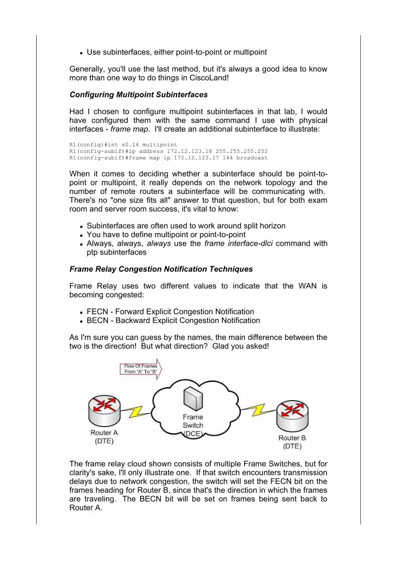
Frame Relay Congestion Notification Techniques
Frame Relay uses two different values to indicate that the WAN isbecoming congested:
FECN - Forward Explicit Congestion Notification BECN - Backward Explicit Congestion Notification
As I'm sure you can guess by the names, the main difference between thetwo is the direction! But what direction? Glad you asked!
The frame relay cloud shown consists of multiple Frame Switches, but forclarity's sake, I'll only illustrate one. If that switch encounters transmissiondelays due to network congestion, the switch will set the FECN bit on theframes heading for Router B, since that's the direction in which the framesare traveling. The BECN bit will be set on frames being sent back toRouter A.

When a frame arrives at a router with the FECN bit set, that meanscongestion was encountered in the direction in which the frame wastraveling.
When a frame arrives at a router with the BECN bit set, congestion wasencountered in the opposite direction in which the frame was traveling.
The Discard Eligible bit is considered a Frame Relay congestionnotification bit, but the purpose is a bit different from the BECN andFECN. Frames are sometimes dropped as a result of congestion, andframes with the DE bit set will be dropped before frames without that bitset. Basically, setting the DE bit on a frame indicates data that'sconsidered less important than data without the DE bit set.
The FECN, BECN, and DE values can be seen with show frame pvc.
R1#show frame pvc
PVC Statistics for interface Serial0 (Frame Relay DTE)
Active Inactive Deleted Static Local 2 0 0 0 Switched 0 0 0 0 Unused 0 0 0 0
DLCI = 122, DLCI USAGE = LOCAL, PVC STATUS = ACTIVE, INTERFACE = Serial0
input pkts 30 output pkts 0 in bytes 2280 out bytes 0 dropped pkts 0 in FECN pkts 0 in BECN pkts 0 out FECN pkts 0 out BECN pkts 0 in DE pkts 0 out DE pkts 0 out bcast pkts 0 out bcast bytes 0 pvc create time 00:07:45, last time pvc status changed 00:06:55
And speaking of PVC Status messages....
PVC Status Messages
When you check PVCs with show frame-relay pvc, you'll see one of threestatus messages for each PVC:
active inactive deleted
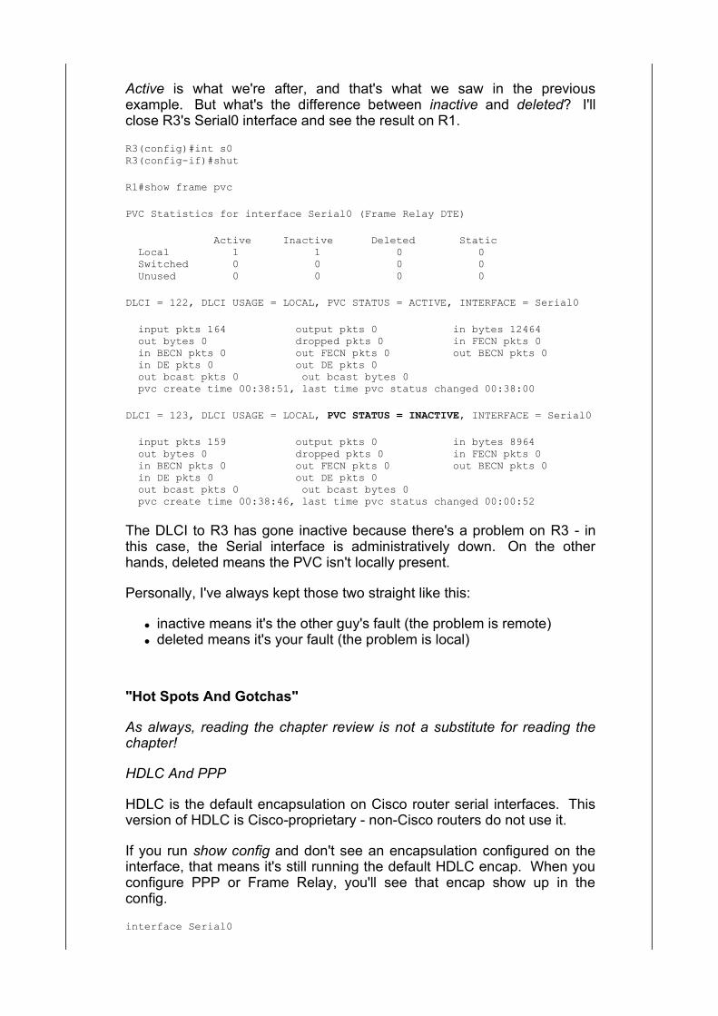
Active is what we're after, and that's what we saw in the previousexample. But what's the difference between inactive and deleted? I'llclose R3's Serial0 interface and see the result on R1.
R3(config)#int s0R3(config-if)#shut
R1#show frame pvc
PVC Statistics for interface Serial0 (Frame Relay DTE)
Active Inactive Deleted Static Local 1 1 0 0 Switched 0 0 0 0 Unused 0 0 0 0
DLCI = 122, DLCI USAGE = LOCAL, PVC STATUS = ACTIVE, INTERFACE = Serial0
input pkts 164 output pkts 0 in bytes 12464 out bytes 0 dropped pkts 0 in FECN pkts 0 in BECN pkts 0 out FECN pkts 0 out BECN pkts 0 in DE pkts 0 out DE pkts 0 out bcast pkts 0 out bcast bytes 0 pvc create time 00:38:51, last time pvc status changed 00:38:00
DLCI = 123, DLCI USAGE = LOCAL, PVC STATUS = INACTIVE, INTERFACE = Serial0
input pkts 159 output pkts 0 in bytes 8964 out bytes 0 dropped pkts 0 in FECN pkts 0 in BECN pkts 0 out FECN pkts 0 out BECN pkts 0 in DE pkts 0 out DE pkts 0 out bcast pkts 0 out bcast bytes 0 pvc create time 00:38:46, last time pvc status changed 00:00:52
The DLCI to R3 has gone inactive because there's a problem on R3 - inthis case, the Serial interface is administratively down. On the otherhands, deleted means the PVC isn't locally present.
Personally, I've always kept those two straight like this:
inactive means it's the other guy's fault (the problem is remote) deleted means it's your fault (the problem is local)
"Hot Spots And Gotchas"
As always, reading the chapter review is not a substitute for reading thechapter!
HDLC And PPP
HDLC is the default encapsulation on Cisco router serial interfaces. Thisversion of HDLC is Cisco-proprietary - non-Cisco routers do not use it.
If you run show config and don't see an encapsulation configured on theinterface, that means it's still running the default HDLC encap. When youconfigure PPP or Frame Relay, you'll see that encap show up in theconfig.
interface Serial0

no ip address (running default setting of HDLC)
!interface Serial1 no ip address encapsulation ppp (obviously NOT running the default)
If your network requires any of the following services, you're "limited" toPPP, because HDLC will not support any of these features:
PPP callback PAP or CHAP for authentication and increased security PPP multilink (logical bundling of physical links) Compression (Stacker or Predictor) Error Detection and Correction Encapsulation capabilities for multiple routed protocols (AppleTalk
and IPX in addition to IP)
The Link Control Protocol (LCP) handles almost all of the negotiations forPPP regarding those features.
An encapsulation mismatch - one end configured for HDLC, the other forPPP - will result in the line protocol going down and IP connectivitybetween the points being lost.
CHAP requires passwords to match, so if each router in a PTP link isusing a different password, authentication will fail. debug ppp negotiationcan help you spot this issue, as will debug ppp authentication.
CHAP uses a three-way handshake during the authentication process.PAP does not.
HDLC, PPP, PAP, CHAP, and Frame Relay are all for use on Cisco serialinterfaces only; you will not use them on Ethernet or Loopback interfaces.
Cisco routers are DTEs by default. You can configure them as DCEs forhome lab use, but in production networks the DCEs will likely beCSU/DSUs or even a modem. Whether it's a modem or CSU/DSU, it'sthat device that must supply clock rate to the DTE. Without the clockrate,the line protocol will go down.
Frame Relay
Frame Relay's biggest advantage over other WAN technologies is its lowcost.
The "big five" Frame Relay troubleshooting commands - be familiar withtheir output!
show frame lmi show frame pvc show frame map show ip interface show interface serial
Frame Relay is a non-broadcast multi-access network (NBMA), packet-
switching technology that is commonly used with hub-and-spoke networkslike the one you saw here in this chapter.
For total connectivity in a Frame Relay multipoint network, all routers stillhave to be on the same subnet; FR is a Layer 2 technology, so there's norouting going on at that level. You should still use the frame-relay mapcommand to create frame mappings on multipoint interfaces.
Always use the frame-relay interface-dlci command on point-to-pointsubinterfaces. The router will not allow you to use the frame-relay mapcommand on point-to-point interfaces:
R1(config)#int s0.1 point-to-pointR1(config-subif)#frame map ip 172.12.123.1 122 broadcastFRAME-RELAY INTERFACE-DLCI command should be used on point-to-pointinterfaces
Frame Relay DLCIs are locally significant only; you can use DLCIs onmultiple routers in the same network, though most real-world networks donot do so. That helps avoid confusion. :) Using the same DLCI numbersthroughout the network is sometimes called global addressing.
The DLCI is simply a local numeric identifier between the local router andthe downstream FR switch. When writing frame map statements, alwaysmap the local DLCI to the remote IP address.
To avoid Split Horizon issues, we basically have three choices.
Use point-to-point interfaces (recommended over the other options) Disable SH with the no ip split-horizon interface-level command Configure a logical full mesh between all routers (not scalable)
The broadcast option in frame map statements is not required, but it isgenerally configured as this option allows broadcast and multicast trafficto cross the frame cloud correctly. Since these broadcasts and multicastsinclude routing protocol updates and Hello packets, it's a good idea to usethis option!
The show frame map command shows you whether a frame mapping wascreated statically or dynamically. If you see static, that map was createdwith the frame map command. If you see dynamic, Inverse ARP createdit. If you see a map to 0.0.0.0, that was also created by Inverse ARP. Itreally doesn't hurt anything, but I've always had to reload the router to getrid of it. Usually not worth the trouble. :)
The Frame Relay encapsulation types are Cisco (the default) and IETF. Ifyou are using non-Cisco routers in the dreaded multivendor environment,you must use IETF.
R1(config)#int s0R1(config-if)#encap frame ? ietf Use RFC1490/RFC2427 encapsulation <cr>
The Frame Relay LMI types are:
Cisco (the default) ansi q933a
If the LMI does not match between the DTE and the DCE, the lineprotocol will go down and IP connectivity goes with it.
The "big three" Frame Relay congestion notification values:
FECN (Forward Explicit Congestion Notification) BECN (Backward Explicit Congestion Notification) DE (Discard Eligible)
FECNs indicate that congestion was encountered in the direction theframe was traveling. BECNs indicate congestion was encountered in theopposite direction in which the frame was traveling. When the DE bit isset, that indicates a frame that should be dropped first in case framesneed to be dropped due to network congestion.
The LMI Autosense feature allows a Cisco router to figure out what LMItype the Frame Switch is using. It's a three-step process:
The DTE sends three LMI messages, one of each type The DCE (Frame Switch) responds with an LMI of one of those three
types The DTE then starts sending only the matching LMI type
When you check PVCs with show frame-relay pvc, you'll see one of threestatus messages for each PVC:
active inactive ( something's wrong on the remote end of the connection) deleted (something's wrong on the local end of the connection)
Back To Index
Copyright © 2011 The Bryant Advantage. All Rights Reserved.