02ic(interface configuration guide)
DESCRIPTION
(Interface Configuration Guide)TRANSCRIPT

User Manual - Configuration Guide (Volume 1)Versatile Routing Platform Table of Contents
i
Table of Contents
Chapter 1 Interface Configuration Overview ....................................................................... 1-1
1.1 Interface Overview .................................................................................................... 1-1
1.2 Interface Configuration.............................................................................................. 1-1
1.2.1 Interface Configuration Mode ........................................................................... 1-1
1.2.2 Set Interface Description.................................................................................. 1-21.2.3 Set Time Interval for Flow Control Statistics...................................................... 1-2
1.3 Interface Configuration Method .................................................................................. 1-2
1.4 Interface Monitoring and Maintenance........................................................................ 1-3
Chapter 2 Configuring LAN Interface .................................................................................. 2-1
2.1 Ethernet Interface ..................................................................................................... 2-1
2.1.1 Ethernet Interface Overview............................................................................. 2-1
2.1.2 Configuring Ethernet Interface.......................................................................... 2-1
2.1.3 Monitoring and Maintenance of Ethernet Interface............................................. 2-42.1.4 Typical Ethernet Interface Configuration Example ............................................. 2-4
2.1.5 Fault Diagnosis and Troubleshooting of Ethernet Interface................................. 2-5
Chapter 3 Configuring WAN Interface ................................................................................. 3-1
3.1 Asynchronous Serial Port .......................................................................................... 3-13.1.1 Asynchronous Serial Ports Overview................................................................ 3-1
3.1.2 Configuring Asynchronous Serial Port .............................................................. 3-1
3.2 AUX Interface........................................................................................................... 3-7
3.2.1 Introduction to AUX Interface ........................................................................... 3-7
3.2.2 AUX Interface Configuration............................................................................. 3-73.2 Synchronous Serial Port ............................................................................................ 3-7
3.2.1 Synchronous Serial Ports Overview.................................................................. 3-7
3.2.2 Configuring Synchronous Serial Port ................................................................ 3-8
3.3 ISDN BRI Interface.................................................................................................. 3-13
3.3.1 ISDN BRI Interface Overview......................................................................... 3-133.3.2 Configuring ISDN BRI Interface...................................................................... 3-14
3.4 cE1/PRI Interface.................................................................................................... 3-14
3.4.1 cE1/PRI Overview ......................................................................................... 3-14
3.4.2 Configuring cE1/PRI Interface........................................................................ 3-15
3.4.3 Monitoring and Maintenance of cE1/PRI Interface ........................................... 3-19
Chapter 4 Configuring Logic Interface ................................................................................ 4-1
4.1 Dialer Interface ......................................................................................................... 4-1
4.1.1 Dialer Interface Overview................................................................................. 4-14.1.2 Configuring Dialer Interface.............................................................................. 4-1

User Manual - Configuration Guide (Volume 1)Versatile Routing Platform Table of Contents
ii
4.2 Sub-Interface............................................................................................................ 4-1
4.2.1 Sub-Interface Overview ................................................................................... 4-1
4.2.2 Configuring Sub-Interface................................................................................ 4-2
4.3 Backup Center Logic Channel.................................................................................... 4-54.3.1 Backup Center Logic Channel Overview........................................................... 4-5
4.3.2 Configuring Backup Center Logic Channel........................................................ 4-5
4.4 Virtual-Template and Virtual Interface......................................................................... 4-5
4.4.1 Virtual-Template and Virtual Interface Overview ................................................ 4-5
4.4.2 Configuring Virtual-Template............................................................................ 4-54.4.3 Monitoring and Maintenance of Virtual-Template and Virtual Interface................ 4-7
4.4.4 Fault Diagnosis and Troubleshooting of Virtual-Template................................... 4-7
User Manual - Configuration Guide (Volume 1)Versatile Routing Platform
Chapter 1Interface Configuration Overview
1-1
Chapter 1 Interface Configuration Overview
1.1 Interface Overview
The router interface refers to the part through which the router system exchanges dataand interacts with other devices in the network. It functions to implement dataexchange between the router and other network devices.
VRP supports physical interface and logic interface on the router.
Physical interface is an interface actually exists and can be supported bycorresponding devices, such as the Ethernet interface and synchronous/asynchronousserial port. There are two types of physical interfaces. One is LAN interface, whichmainly refers to the Ethernet interface through which the router can exchange data withthe network devices in LAN. The other is WAN interface includingsynchronous/asynchronous serial port, asynchronous serial port, AUX interface,cE1/PRI, ISDN BRI and voice interface, etc. Through the WAN interface, the router canexchange data with the network devices in the external network.
Logic interface is an interface doesn’t physically exist and needs to be establishedthrough configuration, and can also exchange data. Logic interface includes the Dialerinterface, sub-interface, backup center logic channel and virtual-template.
1.2 Interface Configuration
1.2.1 Interface Configuration Mode
To facilitate configuration and maintenance of the interface, the interface configurationmode is set in VRP software. Interface commands will be effective only when used inthe configuration mode of relevant interfaces.
I. Entering the interface configuration mode.
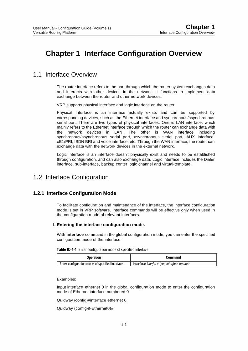
With interface command in the global configuration mode, you can enter the specifiedconfiguration mode of the interface.
Table IC-1-1 Enter configuration mode of specified interface
Operation Command
Enter configuration mode of specified interface interface interface-type interface-number
Examples:
Input interface ethernet 0 in the global configuration mode to enter the configurationmode of Ethernet interface numbered 0.
Quidway (config)#interface ethernet 0
Quidway (config-if-Ethernet0)#

User Manual - Configuration Guide (Volume 1)Versatile Routing Platform
Chapter 1Interface Configuration Overview
1-2
& Note:
In VRP, the command to enter E1 interface configuration mode is controller e1, which is different from thecommand of other interfaces.
II. Exiting the interface configuration mode.
In the interface configuration mode, input exit to return to the global configurationmode.
1.2.2 Set Interface Description
VRP has a configuration item of interface description for router’s physical interface.Interface description is mainly used to help identify the usage of interface. Please usethis command in interface configuration mode.
Table IC-1-2 Set interface description
Operation Command
Set interface description description interface-descriptionRecover default interface description. no description
1.2.3 Set Time Interval for Flow Control Statistics
VRP system counts interface flow every interval time and calculates unit flow as thereference for backup center. Other flow control methods (including the dialerthreshold command of DDR-MP) need this parameter. This command is used to setthe time interval for performing flow statistics on interfaces. It can be used on anyinterfaces.
Perform the following task in global configuration mode.
Table IC-1-3 Set interface description
Operation Command
Set interval time for flow control on the interface flow-interval interval-time
Interval time is 5 minutes by default.
1.3 Interface Configuration Method
Before configuring an interface, it is necessary to have a clear idea about thenetworking requirement and networking diagram. Following operations must beimplemented at least for the interface configuration.
l If this interface is a physical interface, be clear about the connection state, workingmode of the physical interface to be selected and related working parameters.
l If this interface is a WAN interface, appoint the encapsulated link layer protocoland working parameters that should be abided by for the opposite port connectedwith this interface.

User Manual - Configuration Guide (Volume 1)Versatile Routing Platform
Chapter 1Interface Configuration Overview
1-3
l Configure network protocol (such as IP) address of this interface.l Configure the static route that can reach the destination network via this interface,
or configure working parameters of the dynamic route protocol on this interface.l If this interface supports dial, please configure dial mapping, DDR working
parameters and management to Modem.l If this interface acts as the main interface or backup interface at the backup center,
please configure related working parameters of the backup center.l If the firewall is to be established on this interface, please configure parameters
about related message filtering or address conversion.There are lots of parameters to be configured in the interface mode. So, this part willmainly introduce configurations of some parameters special for the physical interface,and briefly introduce the logic interface definition. Configurations about the link layerprotocol, network layer protocol, parameter and some special functions (such as dial,backup center, and firewall) will be introduced specially in other parts of this manualand no further details are provided here.
1.4 Interface Monitoring and Maintenance
Please use the following commands in relevant configuration mode.
Table IC-1-4 Interface monitoring and maintenance
Operation Command
Show current running state and statistic information of theinterface (in any configuration mode) show interface [interface-type interface-number]
Clear interface statistic information (in privileged user mode) clear port [interface-type interface-number]Shut down interface (in interface configuration mode) shutdownRestart interface (in interface configuration mode) no shutdown
These commands are described respectively as follows:1) show interface command displays current running state and statistic information
of the interface If relevant interface name is not specified, the running states andstatistic information of all interfaces will be displayed. That is:
To view information of all interfaces, enter:
Quidway#show interface
To view information of specific interface, such as Serial 0, enter:
Quidway#show interface serial 0
For example: after executing the command show interface serial 0, the followinginformation is displayed:Serial0 is down, line protocol is downDescript: HUAWEI, Quidway Router, Serial InterfaceThe Maximum Transmit Unit is 1500. The keepalive is 10(sec)Internet Address is 10.110.10.15/21Encapsulation is PPPLCP initialQueueing strategy: FIFOOutput queue: (size/max/drops) 0/75/0Interface is no cable, baudrate is 64000 5 minutes input rate 0 bytes/sec, 0 packets/sec 5 minutes output rate 0 bytes/sec, 0 packets/sec 0 packets input, 0 bytes 0 input error 0 packets output, 0 bytes
User Manual - Configuration Guide (Volume 1)Versatile Routing Platform
Chapter 1Interface Configuration Overview
1-4
0 output errorDCD=DOWN DTR=DOWN DSR=DOWN RTS=DOWN CTS=DOWN
The above information includes:
l Physical state and protocol state of the interface.l Interface physical features (synchronous/asynchronous, DTE/DCE, clock
selection, baud rate and external cable).l Interface IP address.l Interface-encapsulated link layer protocol, link layer protocol running state and
statistic information.l Statistic information of input/output message of interface2) clear port command is used to clear the statistic information of input/output
message of the interface. If relevant interface name is not specified, the statisticinformation of all interfaces will be cleared.
3) shutdown/no shutdown command is used to shut down and restart interface.Sometimes, the modification of interface parameters can not take effectimmediately. In this case, the new parameters can not take effect unless theinterface is shut down first and then restarted.
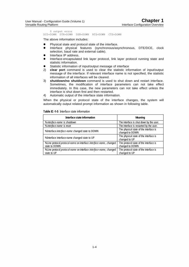
4) Automatic output of the interface state information.When the physical or protocol state of the interface changes, the system willautomatically output related prompt information as shown in following table.
Table IC-1-5 Interface state information
Interface state information Meaning
% interface-name is shutdown The interface is shut down by the user.% interface-name is reset The interface is restarted by the user.
%Interface interface-name changed state to DOWN The physical state of the interface ischanged to DOWN
%Interface interface-name changed state to UP The physical state of the interface ischanged to UP
%Line protocol protocol-name on interface interface-name , changedstate to DOWN
The protocol state of the interface ischanged to DOWN
%Line protocol protocol-name on interface interface-name, changedstate to UP
The protocol state of the interface ischanged to UP

User Manual - Configuration Guide (Volume 1)Versatile Routing Platform
Chapter 2Configuring LAN Interface
2-1
Chapter 2 Configuring LAN Interface
The local area network (LAN) mainly includes Ethernet and Token-Ring network.Currently, Ethernet has become the most important LAN networking technology thanksto its high flexibility, relative simplicity and easy implementation.
Presently, VRP-supported LAN interface is Ethernet interface, including conventionalEthernet interface and fast Ethernet interface.
2.1 Ethernet Interface
2.1.1 Ethernet Interface Overview
Ethernet interface of Quidway series router comprises conventional Ethernet interfaceand fast Ethernet interface.
The conventional Ethernet interface complies with 10Base-T physical layerspecifications, working at 10Mbit/s and in two modes: full duplex and half duplex.
The fast Ethernet interface complies with 100Base-T and also 10Base-T physical layerspecifications, working at 10Mbit/s or 100Mbit/s, and in two modes: half duplex and fullduplex. With the auto-negotiation capability, it can consult other network devices todetermine and automatically select the optimum working mode and rate, thus greatlysimplifying the configuration and management of the system.
The configuration of conventional Ethernet interface is basically the same as that of fastEthernet interface. But the former is simpler, and has less configuration items.Therefore, this chapter mainly introduces the configuration of fast Ethernet interface.
2.1.2 Configuring Ethernet Interface
I. Configuration task list of Ethernet interface
l Enter configuration mode of specified Ethernet interfacel Set network protocol addressl Set frame format of sending messagel Set MTUl Select working rate of fast Ethernet interfacel Select working mode of Ethernet interfacel Enable or disable internal loopback.The specified Ethernet interface can not be configured unless you enter itsconfiguration mode. It's necessary to configure IP address. For other parameters, it'srecommended to use default values, which can ensure the system to work normally inmost cases.
II. Entering configuration mode of specified Ethernet interface
Please use the following command in the global configuration mode.

User Manual - Configuration Guide (Volume 1)Versatile Routing Platform
Chapter 2Configuring LAN Interface
2-2
Table IC-2-1 Enter configuration mode of specified Ethernet interface
Operation Command
Enter configuration mode of specified Ethernet interface interface ethernet interface-number
III. Setting network protocol address
VRP supports IP and IPX at Ethernet interface. Therefore, it is necessary to configureIP or IPX network address. Please refer to “Network Protocol Configuration” part in thismanual.
Please use the following commands in Ethernet interface configuration mode.
Table IC-2-2 Set IP network protocol address
Operation Command
Set IP network protocol address ip address ip-address ip-mask [secondary]Cancel IP network protocol address no ip address ip-address ip-mask [secondary]
When an Ethernet interface is configured with two or more IP addresses, use keyword"secondary" to identify them.
Table IC-2-3 Set IPX network protocol address
Operation Command
Specify IPX network node value ipx routing [node]Delete IPX network node value. no ipx routingSpecify IPX network number ipx network network-numberDelete IPX network number no ipx network
node value is the MAC address of the first Ethernet interface in the router by default.
The ipx routing command and no ipx routing command should be used in globalconfiguration mode.
IV. Setting frame format of sending message
Both Ethernet_ II and Ethernet_ SNAP can support IP and IPX. The Ethernet interfacecan identify these two formats out of received frame, but can only choose one frameformat for the sent frame.
Please use the following commands in Ethernet interface configuration mode.
Table IC-2-4 Set frame format of sending message
Operation Command
Set frame format of sending message send-frame-type {Ethernet_II | Ethernet_SNAP}Recover default frame format of sending message no send-frame-type
The frame format of sending message is Ethernet_II by default.

User Manual - Configuration Guide (Volume 1)Versatile Routing Platform
Chapter 2Configuring LAN Interface
2-3
V. Setting MTU
Maximum transmission unit (MTU) will influence the fragmentation and reassembling ofnetwork message.
Please use the following commands in Ethernet interface configuration mode.
Table IC-2-5 Set MTU
Operation Command
Set MTU mtu ethernet-mtuRecover MTU default value no mtu
Value ranges and default values of MTUs with different link layer encapsulation formatsare different. When Ethernet_II frame format is adopted, MTU value range will be 46-1500 with default value 1500, and when Ethernet_SNAP frame format is adopted, MTUvalue range will be 46-1492 with default value 1492.
VI. Selecting working rate of fast Ethernet interface
As described before, the fast Ethernet interface can work at rates of 10Mbit/s and100Mbit/s. Therefore, it is possible to select interface working rate with followingcommand in Ethernet interface configuration mode.
Table IC-2-6 Select working rate of fast Ethernet interface
Operation Command
Select working rate of fast Ethernet interface speed {auto | 100 | 10}
The default is “Auto”, i.e. the system automatically chooses an optimum working rate.The user can also specify the interface working rate. But the rate specified must be thesame as that of the actually connected network.
VII. Selecting working mode of Ethernet interface
As described above, the Ethernet interface can work in full duplex or half duplex mode.The router Ethernet interface should work in half duplex mode when connected withHUB and in full duplex mode when connected with LANSwitch. Therefore, it is possibleto select working mode with the following command in Ethernet interface configurationmode.
Table IC-2-7 Select working mode of Ethernet interface
Operation Command
Select working mode of Ethernet interface duplex {auto | full | half}
The default is “Auto”, i.e. the system automatically chooses an optimum working mode.
VIII. Enabling or disabling internal loopback.
When performing special function test to Ethernet interface, it needs to be set asinternal loopback sometimes. Therefore, it is possible to enable internal loopback withthe following commands in Ethernet interface configuration mode.

User Manual - Configuration Guide (Volume 1)Versatile Routing Platform
Chapter 2Configuring LAN Interface
2-4
Table IC-2-8 Enable or diable internal sel-loop
Operation Command
Enable internal loopback loopbackEnable internal loopback no loopback
The default is to disable internal loopback.
2.1.3 Monitoring and Maintenance of Ethernet Interface
The following command can be used to specify the state of Ethernet interface inprivileged user mode, so that specified Ethernet interface can be monitored andmaintained.
Table IC-2-9 Show the state of specified Ethernet interface
Operation Command
Show the state of specified Ethernet interface show interface ethernet interface-number
For example:
! Show the state of Ethernet 0
Quidway#show interface ethernet 0
The system displays:Ethernet0 is up, line protocol is down Hardware address is 00-e0-fc-00-00-00 Auto-Negotiation is enabled, Duplex AUTO, Speed AUTO Internet address is 10.111.0.8 255.255.0.0 10.111.255.255 Description: Quidway Router, ethernet interface IP Sending Frames' Format is Ethernet_II the Maximum Transmission Unit is 1500 5 minutes input rate 0.00 bytes/sec, 0.00 packets/sec 5 minutes output rate 0.00 bytes/sec, 0.00 packets/sec Input queue: (size/max/drops) 0/1000/0 Queueing strategy: FIFO Output Queue: (size/max/drops) 0/75/0 0 packets input, 0 bytes, 0 no buffers 0 packets output, 0 bytes, 0 no buffers 0 input errors, 0 CRC, 0 frame errors 0 overrunners, 0 aborted sequences, 0 input no buffers
The information displayed above includes the physical state, line state, networkprotocol address, frame encapsulation format and statistic information abouttransceiving message of this Ethernet interface.
2.1.4 Typical Ethernet Interface Configuration Example
I. Networking requirement
As shown below, the Ethernet interfaces of routers A, B, and C are connectedrespectively to IP networks 10.24.40.0, 129.102.0.0 and 202.38.165.0. And these threerouters are connected together via frame relay network.

User Manual - Configuration Guide (Volume 1)Versatile Routing Platform
Chapter 2Configuring LAN Interface
2-5
II. Networking diagram
EthernetEthernet
Router A
Interface address:
Router B Router C
Frame Relay Network
k
Network address:131.109.1.0
Network address:129.125.1. 0
Interface address :Interface address:
Network address:
Interface address:129.102.0.0
Network address:
Ethernet
202.38.165.1
202.38.165.2
10.24.40.0
10.24.40.1
129.102.0. 1
Figure IC-2-1 Networking diagram of Ethernet configuration example
III. Configuration procedure
1) Configure Router A
! Specify the IP address as 10.24.40.1 and the mask as 255.255.255.0.
Quidway (config-if-Ethernet0)#ip address 10.24.40.1 255.255.255.0
! Set MTU of the interface to 1492 bytes and frame format to Ethernet_II.
Quidway(config-if-Ethernet0)# mtu 1492
Quidway(config-if-Ethernet0)# send-frame-type Ethernet_II
2) Configure Router B
! Specify the IP address as 202.38.165.1 and the mask as 255.255.255.0.
Quidway (config-if-Ethernet0)#ip address 202.38.165.1 255.255.255.0
! Set MTU of the interface to 1492 bytes and frame format to Ethernet_II.
Quidway(config-if-Ethernet0)# mtu 1492
Quidway(config-if-Ethernet0)# send-frame-type Ethernet_II3) Configure Router C
! Specify the IP address to be 129.102.0.1 and the mask to be 255.255.255.0.
Quidway (config-if-Ethernet0)#ip address 129.102.0.1 255.255.255.0
! Set MTU of the interface to 1492 bytes and frame format to Ethernet_II.
Quidway(config-if-Ethernet0)# mtu 1492
Quidway(config-if-Ethernet0)# send-frame-type Ethernet_II
2.1.5 Fault Diagnosis and Troubleshooting of Ethernet Interface
The following test methods can be used to judge whether Ethernet interface is faulty:
l Ping the Ethernet interface from the host located in the same LAN as the router toobserve whether the returned messages are correct.

User Manual - Configuration Guide (Volume 1)Versatile Routing Platform
Chapter 2Configuring LAN Interface
2-6
l View the statistic information of two ends of the connection (such as the router andswitch) to observe whether the statistic number of the received error framesincreases quickly.
If either test fails to pass, it indicates that the Ethernet interface of the router or theconnected Ethernet is abnormal.
After confirming the fault, proceed as follows:
Step 1: View whether the LAN connection between the host and router is correct.
If the Ethernet is connected with HUB or LAN Switch, please check the status ofrelevant link indicators on HUB or LAN Switch. If the indicators are on, it means that theEthernet interfaces of the host & router and the network cable are physically correct.Otherwise, please replace such physical equipment as the network adapter, networkcable, router or relevant interface module.
When the Ethernet is connected with unshielded twisted pair and at least one of theconnection parties supports 100Base-TX, rate matching must be taken intoconsideration. If the working rates of two parties do not match, i.e. one works in100Mbit/s mode while the other works in 10Mbit/s mode, then the fault is that the partywith 100Mbit/s configuration shows no connection, while the party with 10Mbit/sconnection shows the connection has been established. Furthermore, the activityindicator of the physical layer blink quickly and messages can’t be received ortransmitted normally.
On checking the connection of fast Ethernet interface of Quidway series router, thefollowing prompt information is very helpful. Both these two pieces of information areoutput on the control console when the user is executing the rate selection command orconnecting the network cable.Ethernet 0: Warning--the link partner do not support 100M modeEthernet 0: Warning--the link partner may not support 10M mode
Here, the first piece of prompt information indicates that the opposite end, which isdetected by the Ethernet interface of Quidway series router, does not support100Mbit/s working rate, while the local end is working at 100Mbit/s rate by force. At thistime, the user should ensure the opposite has been configured correspondingly and isworking in rate of 100Mbit/s. The second prompt information indicates that the opposite,detected by the Ethernet interface of Quidway series router, may not support 10Mbit/sworking rate, while the local end is forced to work in 10Mbit/s rate. Now, the user shouldensure the opposite end to work at the rate of 10Mbit/s. However, when the Ethernetinterface of Quidway series router is connecting 10/100Mbit/s adaptive port of HUB,this information doesn’t mean setting is incorrect.
Step 2: View whether IP addresses of the Ethernet interfaces of the host and router arewithin the same sub-net. That is the network addresses must be the same, only thehost addresses are different. If they are not in the same sub-net, please re-set the IPaddress.
Step 3: Check whether the link layer protocols match one another.
Take for example two link layer protocol standards supporting IP protocol, Ethernet_IIand Ethernet_SNAP: these two link layer protocols have different encapsulationformats and MTUs. MTU of the former has 1500 bytes and MTU of the latter has 1492bytes. Two Ethernet devices can’t communicate reliably unless they are connected withthe same link layer protocol. The Ethernet interface of Quidway series router cansimultaneously receive data frames with Ethernet_II and Ethernet_SNAP formats.However, the format of sending data frame must be in accordance with eitherEthernet_II or Ethernet_SNAP specified by the user. Therefore, please confirmwhether the data frame sending format of the router is the same as that of other hosts.

User Manual - Configuration Guide (Volume 1)Versatile Routing Platform
Chapter 2Configuring LAN Interface
2-7
When the protocols do not match, the cables and interfaces are physically normal, butcan’t be pinged through.
Step 4: View whether the working mode of the Ethernet interface is correct.
When connecting the Ethernet with unshielded twisted pair or fiber, there are twoworking modes: full duplex and half duplex, specified in 10Base-T/100Base-TX/100Base-FX standard. When using HUB, the half-duplex working mode should beselected. When using LAN Switch, if LAN Switch works in half duplex mode, theEthernet interface of the router also works in half duplex mode. If LAN Switch works infull duplex mode, the Ethernet interface of the router works in full duplex mode too. Ifthe working mode is incorrect, i.e. one party of the connection works in full duplex modewhile the other party in half duplex mode, fault will occur. That is, when network flowincreases, the party working in half duplex mode shows frequent network collisions (forexample, if HUB is connected, all the other devices on the whole network segment willshow serious network collisions), while the party working in full duplex mode showslarge amount of error messages received, accompanied with serious message lossesat both parties. In this case, use show interface ethernet command to view the errorratio of transceiving messages of the Ethernet interface. Usually, the collision can beobserved through the status indicator of the network interface.

User Manual - Configuration Guide (Volume 1)Versatile Routing Platform
Chapter 3Configuring WAN Interface
3-1
Chapter 3 Configuring WAN Interface
The wide area network (WAN) can be divided into X.25 network, frame relay network,ATM network and ISDN network according to the line type. Accordingly, the router hassynchronous/asynchronous serial port, ATM interface, ISDN BRI and cE1/PRI.
Presently, VRP-supported WAN interfaces include asynchronous serial port, AUXinterface, synchronous serial port, ISDN BRI and cE1/PRI interfaces.
3.1 Asynchronous Serial Port
3.1.1 Asynchronous Serial Ports Overview
There are two asynchronous serial ports in VRP. One is Serial, which sets thesynchronous/asynchronous serial port to work in asynchronous mode. The other isAsync, a special asynchronous serial port.
You can set asynchronous serial port to dedicated line mode or dialup mode, and thelatter is in more common use. When the asynchronous serial port is connected withModem or ISDN terminal adapter (TA) externally, it can serve as a dialup interface,encapsulating link layer protocol SLIP or PPP, and supporting IP and IPX.
3.1.2 Configuring Asynchronous Serial Port
I. Configuration task list of asynchronous serial port
The configuration task of asynchronous serial port includes:l Set the synchronous/asynchronous serial port to work in asynchronous mode.l Enter the configuration mode of specified asynchronous serial portl Set the asynchronous serial port to work in dialup or dedicated line mode.l Set encapsulation formatl Set baud ratel Set link establishment mode.l Set the interactive check model set stop bit in interactive model Set data bit in interactive model Set flow control model Enable or disable level detectionl Enable or disable internal loopback.l Set MTUThe asynchronous serial port may also need to be configured with SLIP parameter,PPP parameter, DDR parameter, IP address, firewall and backup center parameter asrequired. Please see relevant chapters in this manual for details.

User Manual - Configuration Guide (Volume 1)Versatile Routing Platform
Chapter 3Configuring WAN Interface
3-2
II. Setting the synchronous/asynchronous serial port to work in asynchronousmode
If the physical interface to be configured is synchronous/asynchronous serial port, itmust be set to work in asynchronous mode by executing the following commands. Ifthis physical interface is a special asynchronous serial port, proceed to Step 3.
Please use the following command in the configuration mode ofsynchronous/asynchronous serial port
Table IC-3-1 Set the synchronous/asynchronous serial port to work in asynchronous mode
Operation Command
Set the synchronous/asynchronous serial port to work in asynchronous mode. physical-layer async
The synchronous/asynchronous serial port works in synchronous mode by default.
III. Entering the configuration mode of specified asynchronous serial port
Please use the following commands to enter the configuration mode of the specifiedserial port in global configuration mode.
Table IC-3-2 Enter configuration mode of specified asynchronous interface
Operation Command
Enter the configuration mode of specified asynchronous serial port interface async numberEnter the configuration mode of the specifiedsynchronous/asynchronous serial port (which has been set to workin asynchronous mode)
interface serial number
IV. Setting the asynchronous serial port to work in dialup or dedicated linemode.
For special asynchronous serial port or the asynchronous serial port set fromsynchronous/asynchronous serial port, it is possible to dialup with modem command.Please see “DDR Configuration” part in this manual for other settings and detailedinstructions in dialup mode. In dedicated line mode, ensure that modem command isnot configured, i.e. disable dial with no modem command.
Please use the following commands in the configuration mode of asynchronous serialport.
Table IC-3-3 Set the working mode of asynchronous serial port
Operation Command
Set the asynchronous serial port to work in dial mode. modem {in | out}Set the asynchronous serial port to work in dedicated line mode. no modem
The asynchronous serial port works in dial mode by default, i.e. modem command isconfigured by default. Both calling in and calling out are allowed with modem in andmodem out command.

User Manual - Configuration Guide (Volume 1)Versatile Routing Platform
Chapter 3Configuring WAN Interface
3-3
V. Setting encapsulation format
The encapsulation format refers to the link layer frame format of the data passing by theasynchronous serial port. It can be set as SLIP and PPP.
Please use the following command in the configuration mode of the asynchronousserial port.
Table IC-3-4 Set the encapsulation format of asynchronous serial port
Operation Command
Set the encapsulation format of the asynchronous serial port encapsulation { slip | ppp }
The default encapsulation format is PPP.
VI. Setting baud rate
Please use following command in the configuration mode of the asynchronous serialport.
Table IC-3-5 Set the baud rate of asynchronous serial port
Operation Command
Set baud rate of the asynchronous serial port baudrate baudrate
Default value is 9600bit/s.
When the asynchronous serial port is used in dialup mode, the baud rate only refers tothe communication rate between the asynchronous serial port of the router and Modem.And the rate between two Modems must be determined according to the line qualityafter mutual consultation. Therefore, baud rate settings of asynchronous serial ports oftwo routers at two ends of the line can be inconsistent.
When the asynchronous serial port is used in dedicated line mode, the baud ratesetting must be consistent with the opposite equipment.
& Note:
After the synchronous/asynchronous serial port is set to work in asynchronous mode, the router willautomatically change the baud rate to 9600bit/s.
VII. Setting link establishment mode
There are three link establishment modes for the asynchronous serial port:l Dedicated: after successful dialing, the local end directly uses the set link layer
protocol parameter to establish link with the opposite end. Dedicated mode isusually used when asynchronous serial ports are directly connected.
l Interactive: also called the flow mode, which means two ends of the link interactwith each other after successful dialing. The calling end sends configurationcommand to the receiving end (with the same effect as the user inputsconfiguration command remotely), sets working parameters of the link layer

User Manual - Configuration Guide (Volume 1)Versatile Routing Platform
Chapter 3Configuring WAN Interface
3-4
protocol at the receiving end and then establishes the link. This mode is usuallyused for such man-machine interactions as dumb terminal and dialing, etc.
Please use the following commands in the configuration mode of the asynchronousserial port.
Table IC-3-6 Set the link establishment mode of asynchronous serial port
Operation Command
Set the asynchronous serial port to establish the link in dedicated mode async mode dedicateSet the asynchronous serial port to establish the link in interactive mode async mode interactive
Establish the link in dedicated mode by default.
VIII. Setting flow control mode
When the serial interface sets up a link in interactive mode, there are two flow controlmethods – hardware flow control and software flow control.
In hardware flow control, data sending on the asynchronous serial port is controlled byhardware signal. While sending data, the serial interface auto-detects the CTS signal. Itwill normally send the data when a CTS signal is detected. If no CTS signal is detected,it stops sending the data. In software flow control, data sending on the asynchronousserial port is controlled by software signal. On receipt of the flow control characterXOFF (0x13), the async serial interface will shut down data sending on local interface;on receipt of the flow control character XON (0x11), it will start data sending of localinterface.
If the flow control method is set to normal, the asynchronous serial interface will onlystart software flow control. If the flow control method is set to auto, the interface willstart hardware flow control and software flow control.
Please use the following command in the configuration mode of the asynchronousserial port.
Table IC-3-7 Set the flow control mode of asynchronous serial port
Operation Command
Set the flow control mode of the asynchronous serial port. flowcontrol {normal | auto}
The default flow control mode is auto.
IX. Set the interactive check mode
When the link establishment mode of async serial port is interactive or Tty, the two endsof the link will interact with each other after a successful dial. The calling end will sendconfiguration command to the receiving end and set the interactive parameters of linklayer protocol on the receiving end before the establishment of the link. In practicalapplication (such as terminal server), the router will send configuration command to theterminal and transmit interactive operating parameters of the link layer which are set atlocal end to the opposite end.
This command is used to set the interactive operating parameter of the link layerprotocol ---check mode.

User Manual - Configuration Guide (Volume 1)Versatile Routing Platform
Chapter 3Configuring WAN Interface
3-5
Please perform the following configuration in asynchronous serial interfaceconfiguration mode.
Table IC-3-8 Set the check mode when the async serial port works in interactive mode
Operation Command
Set the check mode when the async serial port works ininteractive mode parity { even | mark | none | odd | space }
By default, none is adopted for nonparity check.
X. set stop bit in interactive mode
This command is used to set another interactive operating parameter of the link layerprotocol---stop bit.
Please perform the following configuration in asynchronous serial interfaceconfiguration mode.
Table IC-3-9 Set the stop bit when the asynchronous serial port works in interactive mode
Operation Command
Set the stop bit when the asynchronous serial port works ininteractive mode stopbits { 1 | 1.5 | 2
By default, there is only 1 stop bit.
XI. Set data bit in interactive mode
This command is used to set another interactive operating parameter of the link layerprotocol---data bit.
Please perform the following configuration in asynchronous serial interfaceconfiguration mode.
Table IC-3-10 Set the data bit when the asynchronous serial port works in interactive mode
Operation Command
Set the data bit when the asynchronous serial port works ininteractive mode databits { 5 | 6 | 7 | 8 }
5, 6, 7 and 8 stand for 5, 6, 7 and 8 data bits respectively. By default, there are 8 databits.
IX. Enabling or disabing level detection
If the level detection is disabled for the asynchronous serial port, the system will onlydetect whether the asynchronous serial port connects cables externally andautomatically report its state (UP or DOWN) to the user. If the level detection is enabled,the system will detect DSR signal in addition to the above-mentioned detection. Onlywhen this signal is effective will the system regard the asynchronous serial port as UP.Otherwise, DOWN.

User Manual - Configuration Guide (Volume 1)Versatile Routing Platform
Chapter 3Configuring WAN Interface
3-6
Please use the following commands in the configuration mode of the asynchronousserial port.
Table IC-3-11 Enable or disable the level detection for the asynchronous serial port
Operation Command
Enable the level detection for the asynchronous serial port. detect dsr-dtrDisable the level detection for the asynchronous serial port. no detect dsr-dtr
By default the level detection is enabled for the asynchronous serial port.
X. Enabling or disabling internal loopback.
On performing special function test, the internal loopback is enabled for theasynchronous serial port.
Please use following commands in the configuration mode of the asynchronous serialport.
Table IC-3-12 Enable or disable internal loopback for the asynchronous serial port
Operation Command
Enable internal loopback for the asynchronous serial port. loopbackDisable internal loopback for the asynchronous serial port. no loopback
The internal loopback is disabled by default.
XI. Setting MTU
MTU of asynchronous serial port influences the fragmentation and reassembling of IPnetwork protocol message on this interface.
Please use the following commands in the configuration mode of the asynchronousserial port.
Table IC-3-13 Set MTU of asynchronous serial port
Operation Command
Set MTU of asynchronous serial port mtu mtuRecover MTU default no mtu
The unit of mtu is byte, ranging 128 to 1500, with 1500 as default.
The asynchronous serial port is used in dialup service or dedicated line service. Fordetails about its monitoring, maintenance, typical configuration example, faultdiagnosis and troubleshooting, please see related chapters of “03 WAN ProtocolConfiguration” and “06 DDR Configuration” in this manual.

User Manual - Configuration Guide (Volume 1)Versatile Routing Platform
Chapter 3Configuring WAN Interface
3-7
3.2 AUX Interface
3.2.1 Introduction to AUX Interface
AUX interface is a fixed port provided by Quidway router. It can be used as a commonasynchronous serial interface with the highest speed of 115200bps. With AUX interface,the functions like remote configuration of the router and line backup can beimplemented.
3.2.2 AUX Interface Configuration
I. Entering AUX interface configuration mode
Perform the following configuration in global configuration mode.
Table IC-3-14 Entering AUX interface configuration mode
Operation Command
Enter AUX interface configuration mode interface aux 0
II. AUX interface parameter configuration
AUX interface is configured in a similar way as that of the common asynchronous serialport. Notice that:
1) By default, AUX interface works in Interactive mode.2) When configuring the databits of AUX interface, the parameter of the databits
command cannot be set to 5, that is to say, AUX interface does not support thedatabits to be 5.
3) When configuring the stopbits of AUX interface, the parameter of the stopbitscommand cannot be set to 1.5, that is to say, AUX interface does not support thestopbits to be 1.5.
4) On some Quidway routers of old type, AUX interface does not support thechecking of DSR signal. When using AUX interface, if the interface cannot checkwhether the cable of the peer router has been properly connected, configure theno detect dsr-dtr command to disable the level checking of AUX. And then AUXwill stay UP.
In addition to the above points, AUX interface is configured in the same way as that ofthe asynchronous serial interface. For other relevant configurations, refer to“Asynchronous Serial Interface Configuration” of this manual.
3.2 Synchronous Serial Port
3.2.1 Synchronous Serial Ports Overview
Features of synchronous serial port:
l It can work in two modes: DTE and DCE. Usually, the synchronous serial portserves as DTE and receives DCE-provided clock.

User Manual - Configuration Guide (Volume 1)Versatile Routing Platform
Chapter 3Configuring WAN Interface
3-8
l The synchronous serial port can connect multiple cables externally, such as V.24and V.35. VRP can automatically detect types of cables connected externally andselect electrical characters. There is no need to configure manually.
l The link layer protocols supported by synchronous serial port include PPP, framerelay, LAPB and X.25.
l It supports IP and IPX network layer protocol.l Type of external cable and the working mode (DTE/DCE) of the synchronous
serial port can be viewed with show interface serial command. value the voice output attenuation ranging –14.0 to 14.0 in dB with one digit after thedecimal point.
3.2.2 Configuring Synchronous Serial Port
I. Configuration task list of synchronous serial port
Configuration tasks of the synchronous serial port include:
l Set the synchronous/asynchronous serial port to work in synchronous mode.l Enter the configuration mode of specified synchronous serial port.l Set encapsulation formatl Set line coding mode.l Set baud rate.l Select working clockl Set clock inversionl Enable or disable internal loopback/external echol Enable or disable level detectionl Set MTUPPP/X.25/FR parameters, DDR parameters, IP address, firewall parameters andbackup center parameters should be configured on the synchronous serial interface ifneeded. Refer to the relevant chapters in this manual for details.
II. Setting the synchronous/asynchronous serial port to work in synchronousmode.
Before further configuration, please set the synchronous/asynchronous serial port towork in synchronous mode with the following command in the configuration mode ofsynchronous/asynchronous serial port.
Table IC-3-15 Set the synchronous/asynchronous serial port to work in synchronous mode
Operation Command
Set the synchronous/asynchronous serial port in synchronous mode. physical-layer sync
The synchronous/asynchronous serial port works in synchronous mode by default.
III. Entering the configuration mode of the specified synchronous serial port
In global configuration mode, enter the configuration mode of the specifiedsynchronous serial port with the following command.
User Manual - Configuration Guide (Volume 1)Versatile Routing Platform
Chapter 3Configuring WAN Interface
3-9
Table IC-3-16 Enter configuration mode of specified synchronous interface
Operation Command
Enter the configuration mode of the specified synchronous/asynchronousserial port (which has been set to work in synchronous mode) interface serial number
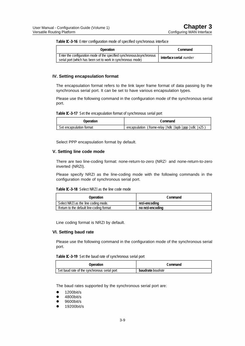
IV. Setting encapsulation format
The encapsulation format refers to the link layer frame format of data passing by thesynchronous serial port. It can be set to have various encapsulation types.
Please use the following command in the configuration mode of the synchronous serialport.
Table IC-3-17 Set the encapsulation format of synchronous serial port
Operation Command
Set encapsulation format encapsulation { frame-relay | hdlc | lapb | ppp | sdlc | x25 }
Select PPP encapsulation format by default.
V. Setting line code mode
There are two line-coding format: none-return-to-zero (NRZ and none-return-to-zeroinverted (NRZI).
Please specify NRZI as the line-coding mode with the following commands in theconfiguration mode of synchronous serial port.
Table IC-3-18 Select NRZI as the line code mode
Operation Command
Select NRZI as the line coding mode. nrzi-encodingReturn to the default line-coding format no nrzi-encoding
Line coding format is NRZI by default.
VI. Setting baud rate
Please use the following command in the configuration mode of the synchronous serialport.
Table IC-3-19 Set the baud rate of synchronous serial port
Operation Command
Set baud rate of the synchronous serial port baudrate baudrate
The baud rates supported by the synchronous serial port are:
l 1200bit/sl 4800bit/sl 9600bit/sl 19200bit/s

User Manual - Configuration Guide (Volume 1)Versatile Routing Platform
Chapter 3Configuring WAN Interface
3-10
l 38400bit/sl 64000bit/sl 72000bit/sl 115200bit/sl 128000bit/sl 384000bit/sl 2048000bit/sFor different physical electrical procedure, the range of baud rate supported by thesynchronous serial port are different.
l V.24DTE/DCE: 1200bit/s-64000bit/sl V.35DCE/DCE, X.21DTE/DCE, EIA/TIA-449DTE/DCE and EIA-530DTE /DCE:
1200bit/s-2048000bit/sWhen two synchronous serial ports are connected, the baud rate on line is determinedat DCE-side. Therefore, when the synchronous serial ports are working in DCE mode,the baud rate is to be set. However, if the ports act as DTE, then the baud rate needn’tbe configured. Default baud rate of synchronous serial port is 64000bit/s.
& Note:
After the synchronous/asynchronous serial port is set to synchronous mode from asynchronous mode, thesystem will automatically change the default baud rate to 64000bit/s.
VII. Selecting working clock
The synchronous serial port works in two modes: DTE and DCE. Different workingmodes has different working clocks.
l If the synchronous serial port is used as DCE, it is necessary to provide clock tothe opposite DTE by choosing DCEclk.
l If the synchronous serial port is used as DTE, the clock provided by the oppositeDCE needs to be accepted. As the receiving clock and transmitting clock of thesynchronous equipment are independent, the receiving clock of DTE can be thetransmitting clock or receiving clock of DCE, or the sending clock of DTE can bethe transmitting clock or receiving clock of DCE. Thus, there will be fourcombinations, i.e. four kinds of clock selections are available at DTE side.
DCE DTE
TxClk
RxClk
Figure IC-3-1 Schematic diagram of synchronous serial port clock selection

User Manual - Configuration Guide (Volume 1)Versatile Routing Platform
Chapter 3Configuring WAN Interface
3-11
Table IC-3-20 Selection method with synchronous serial port serving as DTE-side clock
Selection method Meaning
DTE1 TxClk = TxClk, RxClk = RxClkDTE2 TxClk = TxClk, RxClk = TxClkDTE3 TxClk = RxClk, RxClk = TxClkDTE4 TxClk = RxClk, RxClk = RxClk
& Note:
TxClk stands for transmitting clock, RxClk for receiving clock, the clock before “=” is DTE-side clock, andthat behind “=” is DCE-side clock.
Please use the following commands in the configuration mode of the synchronousserial port.
Table IC-3-21 Select working clock
Operation Command
Select DCE-side synchronous serial port clock clock-select DCEclkSelect DTE-side synchronous serial port clock. clock-select {DTE1 | DTE2 | DTE3 | DTE4}
The clock of DCE-side synchronous serial port is DCEclk by default, and that of DTEside is DTE3 by default.
VIII. Setting clock inversion
In some special cases, the clock will generate half-period delay on the line, which maycause failed interconnection of equipment at two ends or large amount of messagesdiscarded. In this case, the receiving clock signal of DTE-side synchronous serial portcan be inverted to eliminate the influence of delay.
Please use the following commands in the configuration mode of the synchronousserial port.
Table IC-3-22 Set clock inversion
Operation Command
Enable the inversion of receiving clock signal of DTE-side synchronous serial port invert transmit-clockDisable the inversion of receiving clock signal of DTE-side synchronous serial port no invert transmit-clock
The inversion is disabled by default.
& Note:
This command is only effective to certain clock signals provided by some DCEs. Usually, clock inversionshould not be set.

User Manual - Configuration Guide (Volume 1)Versatile Routing Platform
Chapter 3Configuring WAN Interface
3-12
IX. Enabling or disabling level detection
If level detection is disabled for the synchronous serial port, the system will only detectwhether the synchronous serial port connects cables externally and automaticallyreport its state (UP or DOWN) to the user. If level detection is enabled, the system willfurther detect DSR and DCD signals. Only when these two signals are effective will thesystem regard the synchronous serial port as UP.
Please use the following commands in the configuration mode of the synchronousserial port.
Table IC-3-23 Enable or disable level detection for the synchronous serial port
Operation Command
Enable level detection for the synchronous serial port. detect dsr-dtrDisable level detection for the synchronous serial port. no detect dsr-dtr
Level detection is enabled for the synchronous serial port by default.
X. Enable or disable internal loopback/external echo
To perform special function test, the internal loopback/external echo is enabled for thesynchronous serial port.
Please use the following commands in the configuration mode of the synchronousserial port.
Table IC-3-24 Enable/disable internal loopback/external echo for the synchronous serial port
Operation Command
Enable the internal loopback/external echo for the synchronous serial port. loopbackDisable the internal loopback/external echo for the synchronous serial port. no loopback
The internal loopback/external echo is disabled by default.
XI. Configuring MTU
MTU of synchronous serial port affects the fragmentation and reassembling of IPnetwork protocol message on this interface.
Please use the following commands in the configuration mode of the synchronousserial port.
Table IC-3-25 Set MTU of synchronous serial port
Operation Command
Set MTU of synchronous serial port mtu mtuRecover the default value of MTU no mtu
The unit of mtu is byte, ranging between 128-1500, with 1500 as default.
The synchronous serial port is mainly used in dialup service. For details about itsmonitoring and maintenance, typical configuration example, fault diagnosis andtroubleshooting, please see “DDR Configuration” part in this manual.
User Manual - Configuration Guide (Volume 1)Versatile Routing Platform
Chapter 3Configuring WAN Interface
3-13
3.3 ISDN BRI Interface
3.3.1 ISDN BRI Interface Overview
I. Technical background
Integrated services digital network (ISDN) is a new technology developed since 1970’s.It can provide all-digital services from terminal user to terminal user, and fulfill an all-digital transmission mode integrating such services as voice, data, graphics and video.
ISDN is different from conventional PSTN. In conventional PSTN, information is sent tothe switch via analog user loop, converted to digital signal through A/D conversion, andthen resumed to analog signal when reaching the destination user. ISDN realizes thedigital transmission of user loop, implements digital end-to-end communication, andenables various digital and analog information to transmit via the standard digitalinterface. Besides, ITU-T standardizes ISDN services and formulates such protocolsas I.430, Q.921 and Q.931 to make any equipment complying with relevant ISDNstandard of ITU-T able to access ISDN easily.
User-network interface specification of ISDN:
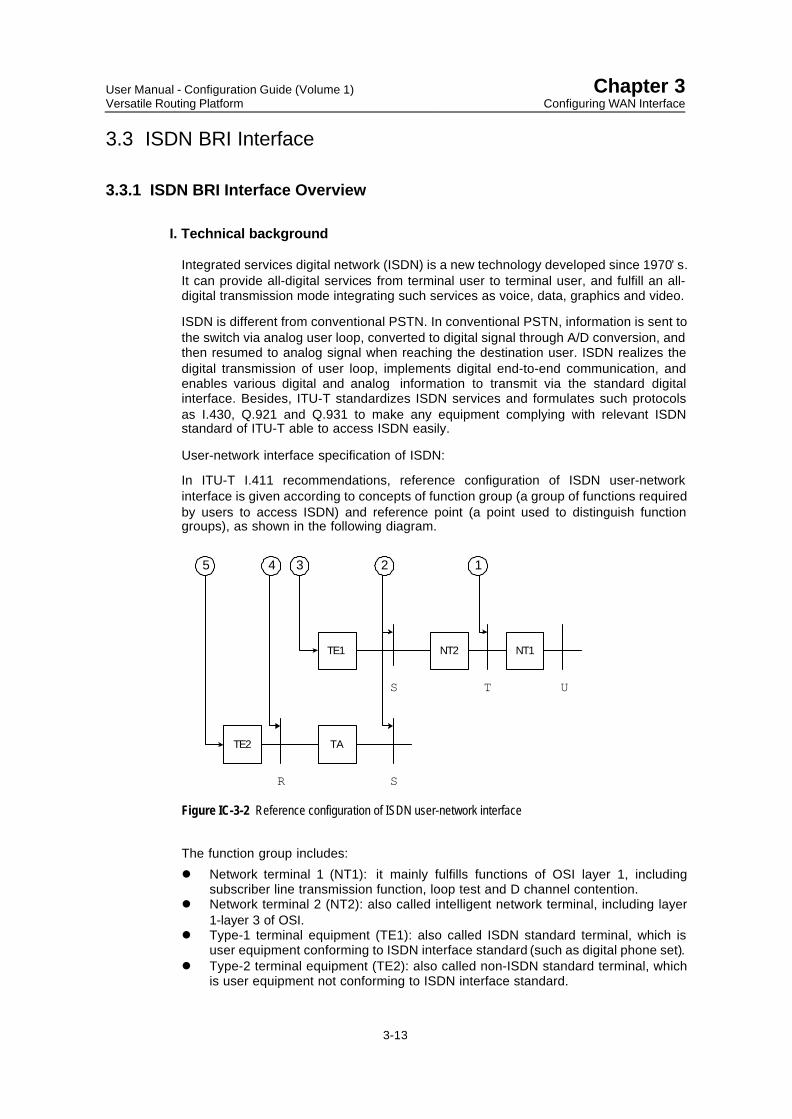
In ITU-T I.411 recommendations, reference configuration of ISDN user-networkinterface is given according to concepts of function group (a group of functions requiredby users to access ISDN) and reference point (a point used to distinguish functiongroups), as shown in the following diagram.
TE2 TA
TE1
S
SR
2345
NT2 NT1
UT
1
Figure IC-3-2 Reference configuration of ISDN user-network interface
The function group includes:
l Network terminal 1 (NT1): it mainly fulfills functions of OSI layer 1, includingsubscriber line transmission function, loop test and D channel contention.
l Network terminal 2 (NT2): also called intelligent network terminal, including layer1-layer 3 of OSI.
l Type-1 terminal equipment (TE1): also called ISDN standard terminal, which isuser equipment conforming to ISDN interface standard (such as digital phone set).
l Type-2 terminal equipment (TE2): also called non-ISDN standard terminal, whichis user equipment not conforming to ISDN interface standard.

User Manual - Configuration Guide (Volume 1)Versatile Routing Platform
Chapter 3Configuring WAN Interface
3-14
l Terminal adapter (TA): it implements adaptation function, making TE2 to accessISDN standard interface.
The reference point includes:
l R reference point: it is between non-ISDN equipment and TAl S reference point: it is between user terminal and NT2.l T reference point: it is between NT1 and NT2.l U reference point: it is between NT1 and line terminal.
II. Preparations before configuration
Be clear about the following items before the configuration:l Whether the interface provided by telecom service provider is ISDN BRI U
interface or ISDN BRI S/T interface: In ITU-T I.411 recommendation, the referencemodel of ISDN user-network interface is given. However, there is worldwidedispute about the position of division point between the user and network. And Uinterface or S/T interface is used according to different nations. In this case, beforepurchasing the router, the user must ensure whether the interface provided by thetelecom server is ISDN BRI U interface or ISDN BRI S/T interface.
l Whether digital service is provided: ISDN can provide integrated services likedigital service or voice service. Since the router is to perform digitalcommunication, the ISDN line that the user applies for must support digital callingservice. Otherwise, data communication can’t be realized.
l Whether to select Point-to-Point connection or Point-to-Multipoint connection(optional): ISDN supports semi-permanent connection function. If the user onlyuses ISDN to connect fixed points, ISDN dedicated line can be used. Otherwise,Point-to-Multipoint connection is required.
l Caller Identification function (optional): On ISDN with CID function, the callernumber can be filtered, so that only a group of user lines can dial in this router,enhancing the security of the network.
3.3.2 Configuring ISDN BRI Interface
Please enter the configuration mode of the specified ISDN BRI interface with thefollowing command in global configuration mode.
Table IC-3-26 Enter the configuration mode of the specified ISDN BRI interface
Operation Command
Enter the configuration mode of the specified ISDN BRI interface interface bri interface-number
Please dial before using ISDN BRI interface. See “06 DDR Configuration” part in thismanual for detailed description of configuration, monitoring and maintenance, typicalconfiguration example, fault diagnosis and troubleshooting of ISDN BRI interface.
3.4 cE1/PRI Interface
3.4.1 cE1/PRI Overview
cE1/PRI interface works in two modes — E1 working mode and cE1/PRI working mode.
In E1 mode, it works like an interface without timeslot whose data bandwidth is 2Mbit/s.It has the same logic features as the synchronous serial port, supports such link layer
User Manual - Configuration Guide (Volume 1)Versatile Routing Platform
Chapter 3Configuring WAN Interface
3-15
protocols as PPP, frame relay, LAPB and X.25 and such network protocols as IP andIPX.
In cE1/PRI mode, it is physically divided into 32 timeslots, respectively correspondingto numbers 0-31. This interface is used in two ways:
l When used as cE1 interface, it can divide all timeslots into random groups. Eachgroup of timeslots, whose logic features are the same as those of synchronousserial port, is bound to serve as a channel-group interface, supporting such linklayer protocols as PPP, frame relay, LAPB and X.25, and network protocols suchas IP and IPX.
l When used as PRI interface, since the timeslot numbered 16 is used as D channelfor signaling transmission, it can only select a group of timeslots out of thosetimeslots except timeslot 16, and bind this group to serve as a pri-group interface.Its logic features are the same as those of ISDN dialing interface that supportsPPP link layer protocol and such network protocols as IP and IPX. In addition,parameters link DDR can also be configured.
3.4.2 Configuring cE1/PRI Interface
I. Configuration task list of cE1/PRI Interface
The configuration tasks of cE1/PRI interface include:
l Enter the configuration mode of the specified cE1/PRIl Set line CODEC formatl Set line clockl Enable or disable internal loopback.l Switch-over of E1 and cE1/PRIl Set frame check model Set timeslot binding mode of cE1/PRI interfacel Set working parameters of channel-groupl Set working parameters of pri-groupl Set working parameters of E1
II. Entering the configuration mode of the specified cE1/PRI interface
Enter the configuration mode of the specified cE1/PRI interface with the followingcommand in global configuration mode.
Table IC-3-27 Enter the configuration mode of the specified cE1/PRI interface
Operation Command
Enter the configuration mode of the specified cE1/PRI interface controller e1 number
III. Setting line CODEC format
cE1/PRI interface supports two line CODEC formats:
AMI format
HDB3 format
Please use the following commands in the configuration mode of cE1/PRI interface.

User Manual - Configuration Guide (Volume 1)Versatile Routing Platform
Chapter 3Configuring WAN Interface
3-16
Table IC-3-28 Set the line CODEC format for cE1/PRI interface
Operation Command
Set the line CODEC format of cE1/PRI interface linecode { ami | hdb3 }Restore the default line CODEC format of cE1/PRI interface no linecode
The default is HDB3 format.
IV. Setting line clock
When cE1/PRI is used as synchronous interface, there are also two working modes:DTE and DCE, and it is also necessary to select line clock. When cE1/PRIs of tworouters are connected directly, two ends must work in DTE and DCE modesrespectively. When cE1/PRI of the router is connected with the switch, the switch worksas DCE, and cE1/PRI of the router should then work in DTE mode. Used as asynchronous interface, cE1/PRI works in DTE mode by default.
Please use following commands in configuration mode of cE1/PRI.
Table IC-3-29 Set the line clock of cE1/PRI interface
Operation Command
Set the line clock of cE1/PRI interface clock { dce | line }Restore the default line clock of cE1/PRI interface no clock
By default, Select DTE clock, i.e., the line clock, on cE1/PRI interface.
V. Enabling or disabling internal loopback.
Please use the following commands in the configuration mode of cE1/PRI interface.
Table IC-3-30 Enable or disable internal loopback of cE1/PRI interface
Operation Command
Enable loopback of cE1/PRI interface loopbackDisable loopback of cE1/PRI interface no loopback
The internal loopback is disabled by default.
VI. Switching-over of working modes of E1 and cE1/PRI
cE1/PRI interface works in two modes: E1 and cE1/PRI.
Please use the following commands in the configuration mode of cE1/PRI interface.
Table IC-3-31 Set the working modes of cE1/PRI interface
Operation Command
Set cE1/PRI interface to work in E1 mode using e1Set cE1/PRI interface to work in cE1/PEI mode using ce1
The default is cE1/PRI working mode.

User Manual - Configuration Guide (Volume 1)Versatile Routing Platform
Chapter 3Configuring WAN Interface
3-17
VII. Setting frame check mode
Working in cE1/PRI mode, cE1/PRI interface supports 4-bit CRC to physical frame.
Please use the following commands in the configuration mode of cE1/PRI interface.
Table IC-3-32 Set frame check mode of cE1/PRI interface
Operation Command
Set the frame check mode of cE1/PRI interface to 4-byte CRC framing crc4Disable frame check to cE1/PRI interface. no framing or framing no-crc4
Frame check is disabled by default.
VIII. Setting timeslot binding mode of cE1/PRI interface
cE1/PRI interface has 32 timeslots. In cE1/PRI mode, it supports two timeslot bindingmodes: channel-group and pri-group. In E1 mode, only pri-group is supported.
Please use the following commands in the configuration mode of cE1/PRI interface.
Table IC-3-33 Set timeslot binding mode of cE1/PRI interface
Operation Command
Bind timeslots of cE1 interface to channel-group channel-group channel-group-number timeslots {number |number1-number2 } [,number | number1-number2...]
Cancel timeslot binding of channel-group no channel-group channel-group
Bind timeslots of cE1 interface to pri-grouppri-group [ timeslots{number | number1-number2}[,number | number1-number2...]]
Cancel timeslot binding of pri-group no pri-group
Here, channel-group-number is the group number of channel, ranging 0 to 30, andnumber is channel number ranging 1 to 31.
On a cE1/PRI interface, up to 31 channel-groups can be bound, but only one pri-groupcan be bound. When bound as pri-group, if no timeslot is specified, all timeslots excepttimeslot 16 will be bound, forming an ISDN PRI interface similar to 30B+D. If timeslot 16is included in the bound timeslots, it will be omitted. If only timeslot 16 is to be bound,binding will be unsuccessful.
Besides, only one timeslot binding mode is supported on a cE1/PRI interface on thesame time, i.e. there can not be channel-group and pri-group at the same time.
IX. Setting working parameters of channel-group
channel-group can be used as a synchronous serial port.
Please enter the corresponding configuration mode with the following command in theconfiguration mode of cE1/PRI interface.
Table IC-3-34 Enter the configuration mode of the synchronous serial port
Operation Command
Enter the configuration mode of the synchronous serial port interface serial interface-number:channel-group-number

User Manual - Configuration Guide (Volume 1)Versatile Routing Platform
Chapter 3Configuring WAN Interface
3-18
Here, interface-number stands for the number of Serial interface added in the systemwhen channel-group is set for cE1/PRI interface, and channel-group-number is the setchannel group number.
The main setting includes:l Working parameters of such link layer protocols as PPP, frame relay, LAPB or
X.25.l IP addressl If the interface serves as main interface or backup interface of the backup center,
it is necessary to set working parameters of the backup center.l To build up firewall on this interface, it is required to set address translation and
bit/s filtering rules.
Please see related parts in this manual for detailed information.
X. Setting working parameters of pri-group
pri-group can be used as an ISDN dialup interface.
Please use the following command to enter the corresponding configuration mode incE1/PRI configuration mode.
Table IC-3-35 Enter the configuration mode of ISDN interface
Operation Command
Enter configuration mode of ISDN interface interface serial interface-number:15
Here, interface-number stands for the number of Serial interface added in the systemwhen pri-group is set for cE1/PRI interface.
The main setting includes:l DDR working parametersl Encapsulation link protocol PPP and its authentication parametersl IP addressl If the interface serves as the main interface or backup interface of the backup
center, it is necessary to configure working parameters of the backup center.l To build up firewall on this interface, it is required to configure the firewall
Please see related parts in this manual for detailed information.
XI. Setting working parameters of E1
E1 can be used as a synchronous serial port.
Please use the following command to enter the corresponding configuration modes incE1/PRI configuration mode (which has been set to E1 mode).
Table IC-3-36 Enter the configuration mode of the synchronous serial port
Operation Command
Enter the configuration mode of the synchronous serial port interface serial interface-number:0
Here, interface-number stands for the number of Serial interface added in the systemwhen pri-group is set for cE1/PRI interface.
The main setting includes:

User Manual - Configuration Guide (Volume 1)Versatile Routing Platform
Chapter 3Configuring WAN Interface
3-19
l Working parameters of such link layer protocols as PPP, frame relay, LAPB orX.25.
l IP addressl If the interface serves as main interface or backup interface of the backup center,
it is necessary to configure working parameters of the backup center.l To build up firewall on this interface, it is required to configure address translation
and bit/s filtering rules.
Please see relevant parts in this manual for detailed information.
3.4.3 Monitoring and Maintenance of cE1/PRI Interface
Please use the following commands to display the state and relevant information ofcE1/PRI interface in privileged user mode, so as to monitor and maintain cE1/PRIinterface
Table IC-3-37 Monitor and maintenance cE1/PRI interface
Operation Command
Show the working state of cE1/PRI interface show controller e1 interface-numberShow the working state of channel-group or pri-group show interface serial interface-number:number
Example 1:
! Show the working state of cE1/PRI interface
Quidway#show controller e1 1
The system displays:E1 1-1 is down. Applique type is E1 - 75 OHM unbalanced Framing is NO-CRC4, Line Code is HDB3, Source Clock is Line.
The information displayed above includes the physical state, application mode, framecheck mode, line CODEC format, and line clock selection.
Example 2:
! Show working state of pri-group
Quidway#show interface serial 9:15
The system displays:Serial9:15 is down, line protocol is down physical layer is E1, baudrate is 1920000 bps Encapsulation is PPP 5 minutes input rate 0.00 bytes/sec, 0.00 packets/sec 5 minutes output rate 0.00 bytes/sec, 0.00 packets/sec Input queue :(size/max/drops) 0/50/0 Queueing strategy: FIFO Output Queue :(size/max/drops) 0/50/0 0 packets input, 0 bytes, 0 no buffers 0 packets output, 0 bytes, 0 no buffers 0 input errors, 0 CRC, 0 frame errors 0 overrunners, 0 aborted sequences, 0 input no buffersTimeslot(s) Used: 1-31

User Manual - Configuration Guide (Volume 1)Versatile Routing Platform
Chapter 3Configuring WAN Interface
3-20
The information displayed above includes the physical state, line state, frameencapsulation format, application mode and statistic information of transceivingmessage of pri-group.
cE1/PRI interface is usually used in dialup service or dedicated line service. For itstypical configuration example, fault diagnosis and troubleshooting, please see relatedchapters of “03 Link Layer Configuration” and “10 DDR Configuration” in this manual.

User Manual - Configuration Guide (Volume 1)Versatile Routing Platform
Chapter 4Configuring Logic Interface
4-1
Chapter 4 Configuring Logic Interface
As described above, the logic interface refers to the interface that can exchange data,but does not exist physically and needs to be established through configuration,including the Dialer interface, sub-interface, backup center logic channel and virtual-template.
4.1 Dialer Interface
4.1.1 Dialer Interface Overview
Dialer interface is a dialup interface. Dial-supporting interfaces on Quidway seriesrouter include synchronous serial port, asynchronous serial port, ISDN BRI interfaceand ISDN PRI interface. VRP realizes the Dial on Demand Routing (DDR) function, andprovides two DDR configuration methods: standard DDR and flexible DDR. Please see"DDR Configuration” part in this manual for detailed information about concepts ofstandard DDR and flexible DDR.
4.1.2 Configuring Dialer Interface
According to different DDR modes, configurations of Dialer interface are:l Configure Dialer interface for standard DDRl Configure Dialer interface for flexible DDRPlease see related chapters in “06 DDR Configuration” part in this manual for detaileddescription, monitoring and maintenance, typical configuration example, fault diagnosisand troubleshooting of the configurations of standard and flexible DDR.
4.2 Sub-Interface
4.2.1 Sub-Interface Overview
VRP provides the concept of sub-interface, which enables user to configure multiplesub-interfaces on single physical interface of Quidway series router.
Sub-interface implements multiple logic interfaces on a physical interface, i.e. toassociate multiple logic interfaces with one physical interface. The logic interfaces thatbelong to the same physical interface will share physical configuration parametersduring work, and they also have independent link layer and network layer configurationparameters.
In Quidway series router, the physical interfaces supporting sub-interface featuresinclude:
l Ethernet interface: when the sub-interface of Ethernet has not been configuredwith VLAN id, it can only support IPX network protocol. After configured with VLANid, it will be able to support both IPX and IP protocols.
l WAN interface of encapsulation frame relay: its sub-interface can support IP andIPX network protocols.

User Manual - Configuration Guide (Volume 1)Versatile Routing Platform
Chapter 4Configuring Logic Interface
4-2
l WAN interface of encapsulation X.25: its sub-interface can support IP and IPXnetwork protocols.
4.2.2 Configuring Sub-Interface
I. Configuration task list of sub-interface
According to different physical interfaces, the configuration tasks of sub-interfacesinclude:
l Configure sub-interfaces of Ethernet interfacel Configure sub-interfaces of WAN interface of encapsulation frame relayl Configure sub-interfaces of WAN interface of encapsulation X.25
II. Configuring sub-interfaces of Ethernet interface
1) Create and delete Ethernet sub-interfaces
Please use the following commands in global configuration mode.
Table IC-4-1 Create and delete Ethernet interface
Operation Command
Create Ethernet sub-interface and enter its configurationmode
rinterface ethernet interface-number.subinterface-number
Delete the specified Ethernet sub-interface no interface ethernet interface-number.subinterface-number
When using the above commands, if corresponding Ethernet sub-interface has beencreated (the same as subinterface-number), enter the configuration mode of this sub-interface directly. Otherwise, first create Ethernet sub-interface with subinterface-number as the specified one, and then enter the configuration mode of this sub-interface.
2) Configure relevant working parametersIf the sub-interface of Ethernet has not been configured with VLAN id, it can onlysupport IPX network protocol. Therefore, only IPX network address and other IPXworking parameters can be configured on this sub-interface. The detailed configurationprocedure and method are similar to those of the Ethernet interface. Please see LANinterface configuration in “Interface Configuration” and IPX configuration in “NetworkProtocol Configuration” of this manual.
After configured with VLAN id, the sub-interface of Ethernet can support IP and IPX.For relevant configuration, refer to LAN interface configuration in “InterfaceConfiguration” and IP configuration in “Network Protocol Configuration” of this manual.
III. Configuring sub-interfaces of WAN interface of encapsulation frame relay
1) Create and delete WAN sub-interfaces
Please use the following commands in global configuration mode.

User Manual - Configuration Guide (Volume 1)Versatile Routing Platform
Chapter 4Configuring Logic Interface
4-3
Table IC-4-2 Create and delete WAN sub-interface
Operation Command
Create WAN sub-interface and enter itsconfiguration mode
interface { serial | async } interface-number.subinterface-number [multipoint | point-to-point ]
Delete specified WAN sub-interfaceno interface { serial | async } interface-number.subinterface-number [ multipoint | point-to-point ]
When using the above commands, if corresponding WAN sub-interface has beencreated (the same as subinterface-number), enter the configuration mode of this sub-interface directly. Otherwise, first create WAN sub-interface with subinterface-numberas the specified one, and then enter the configuration mode of this sub-interface.
2) Configure relevant working parametersThe following items can be configured on the sub-interface of WAN interface ofencapsulation frame relay:
l Frame relay address mapping different from the affiliated WAN interface (i.e. themain interface)
l IP address which is not in the same network segment as the affiliated WANinterface
l IPX network number different from that of the affiliated WAN interface, and otherIPX working parameters
l Virtual circuit of the sub-interfacePlease see chapters in “WAN Protocol Configuration” and “Network ProtocolConfiguration” in this manual for details about the above configurations.
IV. Configuring sub-interfaces of WAN interface of encapsulation X.25
1) Create and delete WAN sub-interfaces
The command is the same as above.2) Configure relevant working parametersThe following items can be configured on the sub-interface of WAN interface ofencapsulation X.25:
l X.25 address mapping different from the affiliated WAN interface (i.e. the maininterface)
l IP address which is not in the same network segment as the affiliated WANinterface
l IPX network number different from that of the affiliated WAN interface, and otherIPX working parameters
l Virtual circuit of the sub-interfacePlease see chapters in “WAN Protocol Configuration” and “Network ProtocolConfiguration” in this manual for details about the above configurations, and sub-interface monitoring and maintenance. No further details are provided here.
V. Typical WAN sub-interface configuration example
1) Networking requirementsAs shown below, WAN interface Serial0 of router A is connected with router B androuter C via public frame relay network. By configuring sub-interfaces on Serial0 ofrouter A, LAN 1 can simultaneously access LAN 2 and LAN 3 via Serial0.
2) Networking diagram

User Manual - Configuration Guide (Volume 1)Versatile Routing Platform
Chapter 4Configuring Logic Interface
4-4
Router A
Router B
Router C
Frame relay
Ethernet 1 Serial0
DLCI=50202.38.160.1
202.38.161.2
129.9.0.0 Ethernet 3
Ethernet 2
DLCI=60
DLCI=70
DLCI=80
202.38.160.2
202.38.161.1
129.10.0.0
129.11.0.0
Figure IC-4-1 Networking diagram of WAN sub-interface configuration example
3) Configuration procedure
! Enter the configuration mode of WAN interface Serial0 of router A
Quidway(config)#interface serial 0
! Select frame relay encapsulation format
Quidway(config-if-Serial0)#encapsulation frame-relay
! Specify DTE as its frame relay terminal type
Quidway(config-if-Serial0)#frame-relay intf-type dte
! Create sub-interface Serial 0.1 on WAN interface Serial0 of router A in point-to pointmode, and enter its configuration mode
Quidway(config)#interface serial 0.1 point-to-point
! Set its IP address to 202.38.160.1 and address mask to 255.255.255.0.
Quidway(config-if-Serial0.1)#ip address 202.38.160.1 255.255.255.0
! Allocate a virtual circuit with DLCI 50 to it.
Quidway(config-if-Serial0.1)#frame-relay interface-dlci 50
! Create sub-interface Serial 0.2 on WAN interface Serial0 of router A in point-to pointmode, and enter its configuration mode
Quidway(config)#interface serial 0.2 point-to-point
! Set its IP address to 202.38,161.1 and address mask to 255.255.255.0.
Quidway(config-if-Serial0.2)#ip address 202.38.161.1 255.255.255.0
! Allocate a virtual circuit with DLCI 60 to it.
Quidway(config-if-Serial0.2)#frame-relay interface-dlci 60
! Configure the static route from router A to LAN2 and LAN3.
Quidway(config)#ip route 129.10.0.0 255.255.0.0 202.38.160.2
Quidway(config)#ip route 129.11.0.0 255.255.0.0 202.38.161.2
Configurations of router B and router C are omitted here. For fault diagnosis andtroubleshooting of sub-interface, please see chapters in “03-Link Layer ProtocolConfiguration” and “04-Network Protocol Configuration” in this manual.

User Manual - Configuration Guide (Volume 1)Versatile Routing Platform
Chapter 4Configuring Logic Interface
4-5
4.3 Backup Center Logic Channel
4.3.1 Backup Center Logic Channel Overview
The backup center not only provides mutual backup between respective interfaces, butalso chooses a certain virtual circuit belonging to X.25 or frame relay as the maininterface or backup interface of the backup center. Please see relevant chapters fordetails about the backup center.
To facilitate configuration, the user can specify relevant logic channel for the above-mentioned virtual circuit and configure working parameters of the backup center in thelogic channel.
4.3.2 Configuring Backup Center Logic Channel
For detailed description, monitoring and maintenance, typical configuration example,fault diagnosis and troubleshooting oriented to the configurations of the backup centerlogic channel, please see “Configuration of Backup Center” in “ReliabilityConfiguration” in this manual.
4.4 Virtual-Template and Virtual Interface
4.4.1 Virtual-Template and Virtual Interface Overview
Virtual-template, just as the name implies, is a template used to configure a virtualinterface, mainly used in VPN and MP.
After setting up the connection of VPN session, it is necessary to create a virtualinterface to exchange data with the opposite end. At this time, the system will choose avirtual-template according to the user’s configuration, and dynamically create a virtualinterface based on the configuration parameters of the template. Please see relatedchapters in “08-VPN Configuration” in this manual for the configuration of VPN.
Similarly, after multiple PPP links are bound as MP, a virtual interface also needs to becreated to exchange data with the opposite end. At this time, select an interfacetemplate to dynamically create a virtual interface.
4.4.2 Configuring Virtual-Template
I. Configuration task list of virtual-interface
In VPN and MP application environments, the system automatically creates anddeletes virtual interface, which is completely transparent to the user. The user onlyneeds to configure VPN or MP at corresponding physical interface, creates andconfigures virtual-template, and then builds up relation between the virtual-templateand relevant physical interface.
The configuration tasks of virtual-template include:l Create and delete virtual-templatel Set working parameters of the virtual-template

User Manual - Configuration Guide (Volume 1)Versatile Routing Platform
Chapter 4Configuring Logic Interface
4-6
l Build up corresponding relation between the virtual-template and relevant physicalinterface.
II. Creating and deleting virtual-template
Please use the following commands in global configuration mode.
Table IC-4-3 Create and delete virtual-template
Operation Command
Create virtual-template and enter its configuration mode interface virtual-template numberDelete the virtual-template no interface virtual-template number
Here, number stands for template number of virtual-template ranging 1 to 25, i.e. theuser can create up to 25 virtual-templates.
In executing interface virtual-template command, if corresponding virtual-templatehas been created, then directly enter the configuration mode of this virtual-template.Otherwise, first create the virtual-template with specified template number.
In deleting the virtual-template, make sure that all of its derived virtual interfaces havebeen removed and this virtual-template is not in use any more.
III. Setting working parameters of virtual-template
Compared with normal physical interface, the virtual-template has the followingfeatures: the link layer protocol only supports PPP, and the network protocol supportsIP and IPX. Therefore, the following working parameters can be set:
l Set working parameters of PPPl Set IP address of virtual interfacel Set IP address (or IP address pool) allocated to PPP opposite endl Set bit/s filtering rules on the virtual interfaceSettings of these parameters on virtual-template are the same as those on normalinterface. Please see related chapters of PPP configuration in “03-WAN ProtocolConfiguration”, IP address configuration in “04-Network Protocol Configuration” andRadius configuration in “07-Security Configuration” in this manual for configurationdetails.
IV. Create corresponding relation between the virtual-template and relatedphysical interface.
In VPN application environment, it is necessary to build up corresponding relationsbetween VPDN group and virtual-template. In MP application environment, it isnecessary to build up corresponding relations between MP and virtual-template.
Please use the following commands in relevant configuration mode.
Table IC-4-4 Create corresponding relation between the virtual-template and related physical interface
Operation Command
Build up corresponding relation between VPDNgroup and virtual-template (in configuration modeof VPDN group)
accept dialin l2tp virtual-template virtual-template-number [remote remote-name]
Build up corresponding relation between MP userand virtual-template (in global configuration mode) multilink-user user-name bind virtual-template number

User Manual - Configuration Guide (Volume 1)Versatile Routing Platform
Chapter 4Configuring Logic Interface
4-7
Please see chapters in “VPN Configuration” and “WAN Protocol Configuration” in thismanual for details about the above commands.
4.4.3 Monitoring and Maintenance of Virtual-Template and Virtual Interface
The virtual interface, automatically created by the system if necessary, will work byusing parameters of related virtual-template. So, it's unnecessary for manualconfiguration. The virtual interface will be deleted because of low-layer linkdisconnection or user intervention.
The following command can be used to specify the state of virtual-template inprivileged user mode.
Table IC-4-5 Show state of the specified virtual-template
Operation Command
Show the state of the specified virtual-template Show interface virtual-template virtual-template-number
For example:
! Show the state of Virtual-Template 1.
Quidway#show interface virtual-template 1
The system displays:Virtual- Template1 is up, line protocol is up physical layer is Virtual Template Encapsulation is PPP 0 packets input, 0 bytes 0 input errors, 0 broadcast, 0 drops 0 packets output, 0 bytes 0 output errors, 0 broadcast, 0 no protocol
The information displayed above includes the physical state, circuit state, frameencapsulation format and statistic information of transceiving message of this virtual-template.
Please see related chapters of “VPN Configuration” and “WAN Protocol Configuration”in this manual for typical configuration examples of virtual-template.
4.4.4 Fault Diagnosis and Troubleshooting of Virtual-Template
Before checking and eliminating faults of virtual-template, first find out the virtual-template is used to create VPN virtual access interface or MP virtual interface, thenlocate the fault of the virtual-template in actual application environment.
Fault 1: fail to create virtual interface.
Troubleshooting: the reasons may be as follows:l The virtual-template is not configured with IP address. Therefore, PPP
consultation fails and the virtual interface can’t turn to Up state.l The virtual-template is not configured with IP address (or IP address pool)
allocated to the opposite end. If it is required to allocate addresses to the oppositeend in actual application, the virtual interface can not meet the requirement, norturn to Up state.
l PPP authentication parameter is set incorrectly. If the opposite end is not the userdefined by the router, PPP consultation will also fail.

User Manual - Configuration Guide (Volume 1)Versatile Routing Platform
Chapter 4Configuring Logic Interface
4-8
Please see related chapters of “VPN Configuration” and “WAN Protocol Configuration”in this manual for more methods of fault diagnosis and troubleshooting of virtual-template.