01|2016 - ringfeder€¦ · · 2016-02-04locking assemblies & locking elements ... couplings...
TRANSCRIPT
US0 1 | 2 0 1 6
Locking Assemblies & Locking Elements
Partner for Performancewww.ringfeder.com
LOC
KIN
G A
SS
EM
BLI
ES
& L
OC
KIN
G E
LEM
EN
TS ·
US
08
|20
14

Today’s RINGFEDER POWER TRANSMISSION GMBH was founded in 1922 in Krefeld, Germany as patent exploitation company for Friction Springs. Today we are a global supplier of top-quality products for the power transmission- and damp- ing technology industries.
RINGFEDER POWER TRANS-MISSION is one of the leading
companies in selected market niches. Through our sustainable, or-ganic growth, targeted acquisitions and attentive proximity to our customers, we are constantly supplementing and developing our range of products in cooperation with our customers and deliver service for the future. Beyond that, RINGFEDER POWER TRANS-MISSION is one of the prime addresses in regard to technical know-how for our discerning customers.
Welcome to your system supplier for every aspect of power transmission
2

Mars Rover: Courtesy NASA/JPL-Caltech
Our world-renowned German brands RINGFEDER, TSCHAN and GERWAH stand for customer-oriented solutions that fulfil the high-est requirements and guarantee our customers a trouble-free sys-tem operation. Under the brand name ECOLOC we offer reliable products off the shelf.
The brand RINGFEDER is world’s leading in the sector of lock- ing devices and damping technology. The GERWAH brand stands for torsionally rigid, elastic couplings as well as safety couplings in the lower torque range, whereas TSCHAN stands for non-shiftable elastic, highly-elastic and torsionally rigid shaft couplings in the higher torque range. The ECOLOC brand includes cost-efficient alternatives from the premium range available for standard use.
Hence, the product portfolio comprises high-quality products with the best cost-benefit ratio, covering all aspects of power trans- mission.
3

Content
Content
Locking Assemblies
Characteristics ................................................................. ......................... Page 8
RINGFEDER® RfN 7012-IN/7012 ........................... ......................... Page 10
RINGFEDER® RfN 7012.2 ........................................... ......................... Page 16
RINGFEDER® RfN 7013.0-IN/7013.0.................... ......................... Page 20
RINGFEDER® RfN 7013.1-IN/7013.1.................... ......................... Page 24
RINGFEDER® RfN 7014 ............................................... ......................... Page 28
RINGFEDER® RfN 7015.0 ........................................... ......................... Page 30
RINGFEDER® RfN 7015.1 ........................................... ......................... Page 32
RINGFEDER® RfN 7515 ............................................... ......................... Page 34
All technical details and information are non-binding and cannot be used as a basis for legal
claims. The user is obligated to determine whether the represented products meet his requi-
rements. We reserve the right at all times to carry out modifications in the interests of technical
progress. Upon the issue of this catalogue all previous brochures and questionnaires on the
products displayed are no longer valid.
Locking Assemblies for bending loadsCharacteristics ................................................................. ......................... Page 48
RINGFEDER® RfN 7012 ............................................... ......................... Page 50
RINGFEDER® RfN 7012.2 ........................................... ......................... Page 54
RINGFEDER® RfN 7015.0 ........................................... ......................... Page 56
RINGFEDER® RfN 7015.1 ........................................... ......................... Page 58
RINGFEDER® RfN 7515 ............................................... ......................... Page 60
Locking Assemblies with central lock nutRINGFEDER® RfN 7070 ............................................... ........................ Page 38
RINGFEDER® RfN 7075 ............................................... ........................ Page 40
RINGFEDER® RfN 7085 ............................................... ........................ Page 42
RINGFEDER® RfN 7090 stainless steel ...................... ................... Page 44
4

Content
Content
ContentLocking Elements
Characteristics ................................................................. ......................... Page 64
RINGFEDER® RfN 8006 ............................................... ......................... Page 66 RINGFEDER® RfN 8006 GSA ................................... ......................... Page 70
Special SolutionsSpecial Locking Assemblies .................................... ........................ Page 88
Installation and removal instructions
Locking Assemblies ....................................................... .......................... Page 94
Locking Elements ............................................................ .......................... Page 108
Locking Assemblies
Characteristics ................................................................. ......................... Page 74
RINGFEDER® RfN 7012-IN/7012 ........................... ......................... Page 76
RINGFEDER® RfN 7013.1 ........................................... ......................... Page 80
RINGFEDER® RfN 7061 ............................................... ......................... Page 82
RINGFEDER® RfN 7110 ............................................... ......................... Page 84
RINGFEDER® RfN 8006 ............................................... ......................... Page 86
Locking Elements
Calculation of hub and shaft Page 92
STAINLESS STEEL
5

RINGFEDER® Locking Assemblies
6

RfN 7012 RfN 7012.2
RfN 7014RfN 7013.0 RfN 7013.1
RfN 7015.0 RfN 7015.1 RfN 7515
7
Characteristics
Inexpensive manufacture – the large tolerances that are possible and the simple turning process guarantee inexpensive manufacture.
Simple installation – only a few screws need to be tightened, alignment to precise angles between the hub and shaft is possible in any position, no fitting work is required.
Simple dismantling – RINGFEDER® Locking Assemblies are fitted with threaded extraction holes, so that no additional auxiliary equipment is necessary, series RfN 7012 is self-releasing.
Large constant reverse-torsion fatigue strength – shaft and hub are ungrooved, so that there is no weakening of these components. Shaft and hub can be designed to be considerably smaller (light, cost and space-saving design possible).
No danger of deflection – RINGFEDER® Locking Assemblies are absolutely backlash-free.
Effect similar to overload protection – after the set frictional connection force has been exceeded the Locking Assemblies simply slide. Valuable machine parts are protected. The Locking Assemblies are subject to the same laws as any other connection with force transmission by friction - not suitable as sliding clutch.
Completely maintenance-free – no follow-up costs.
RINGFEDER® Locking Assemblies
8

Explanations to tables
Basic dimensions when screws are not tightened
d = Inner diameter (decimal notation)
d = Inner ring diameter
D = Outer diameter
DB1 = Collar outer diameter L = Overall length L1 = Overall length without screws L3 = Width of inner ring L4 = Installation length up to collar T = Transmissible torque at given TA
Fax = Transmissible axial force
pW = Surface pressure on shaft at given TA pN = Surface pressure on hub at given TA nSc = Quantity of screws
DG = Thread
SW = Wrench size
TA = Max. tightened torque of the clamping screws
DN min = Min. hub outer diameter depending of the given hub yield point (Rp0,2)
Tmax = Maximum transmissible torque
Gw = Weight
9

ø D
N
LN ≥ 2 · L3
Locking Assembly RfN 7012 · Belt pulley
L
d
D
L3
L1
Locking Assembly RfN 7012 · Dimensions
Locking Assembly RfN 7012 · Location · Calculation of hubs see on page 92-93 (Calculation possible for other hub forms in our calculation program)
RINGFEDER® Locking Assemblies RfN 7012-IN
Characteristics
As the industry standard, the RfN 7012/RfN 7012-IN Locking Assembly is suitable for most applications.
Transmission of high loads – up to 4 RfN 7012/RfN 7012-IN Locking Assemblies can be used in series, the transmis-sible torques and axial forces are added. (Please contact our specialists for assistance).
Bending moment and radial loads – Combined loads can be transmitted. (Please contact our specialists for assistance).
Simplified manufacture – RfN 7012/RfN 7012-IN Locking Assemblies can bridge large clearances without the loss of trans-mission values.
Low risk to contamination – During the tightening process the functional surfaces of the device are under pressure, sufficient enough to keep contaminants out, thereby preserving the integ-rity of the device.
Adjustable transmission values – The screw tightening torque can be varied, thus allowing for different torque trans-mission values. RfN 7012/RfN 7012-IN Locking Assemblies can be tightened and released repeatedly.
Example applications:
Sprockets, gears, coupling hubs, conveyor pulleys, idler wheels, sheaves
10

To continue see next page
RfN 7012-IN
Explanations to tables: Page 9
Locking Assembly dimensions Transmissible torques Surface pressure Locking screws DN min at
or axial forces ISO 4762-12.9 Rp0,2
Shaft Hub 200 300 400
d d x D L L1 L3 T Fax pW pN nSc DG SW TA Gw DHG [N/mm2]
inch inch inch ft-lbs lbs psi pcs. mm ft-lbs lbs inch inch
0.750 3/4 x 1.850 1.083 0.787 0.669 225 7200 35000 14200 8 M 6 x 18 5 13 0.5 8 2.565 2.395 2.227
1.000 1 x 1.969 1.083 0.787 0.669 337 8088 33000 16800 9 M 6 x 18 5 13 0.6 8 2.915 2.679 2.454
1.125 1 1/8 x 2.165 1.083 0.787 0.669 424 9045 30000 15600 9 M 6 x 18 5 13 0.7 8 3.108 2.878 2.655
1.1875 1 3/16 x 2.159 1.108 0.813 0.669 445 8994 31000 17100 9 M 6 x 18 5 13 0.7 8 3.221 2.955 2.702
1.250 1 1/4 x 2.362 1.083 0.787 0.669 459 8813 35000 18600 12 M 6 x 18 5 13 0.7 8 3.666 3.330 3.017
1.375 1 3/8 x 2.365 1.071 0.776 0.669 622 10857 32000 18700 12 M 6 x 18 5 13 0.7 8 3.681 3.341 3.025
1.4375 1 7/16 x 2.559 1.083 0.787 0.669 748 12488 35000 19700 15 M 6 x 18 5 13 0.8 8 4.092 3.689 3.318
1.500 1 1/2 x 2.559 1.083 0.787 0.669 782 12512 33500 19700 15 M 6 x 18 5 13 0.8 8 4.092 3.689 3.318
1.625 1 5/8 x 2.953 1.319 0.945 0.787 1273 18801 39000 21500 12 M 8 x 22 6 30 1.3 10 4.968 4.417 3.926
1.6875 1 11/16 x 2.953 1.319 0.945 0.787 1320 18773 34000 19500 12 M 8 x 22 6 30 1.3 10 4.696 4.240 3.819
1.750 1 3/4 x 2.953 1.319 0.945 0.787 1368 18761 36000 21400 12 M 8 x 22 6 30 1.3 10 4.953 4.408 3.921
1.875 1 7/8 x 3.150 1.319 0.945 0.787 1454 18611 34000 20300 12 M 8 x 22 6 30 1.4 10 5.122 4.597 4.119
1.9375 1 15/16 x 3.150 1.319 0.945 0.787 1498 18556 32000 19700 12 M 8 x 22 6 30 1.4 10 5.037 4.541 4.085
2.000 2 x 3.346 1.319 0.945 0.787 1808 21696 37000 22200 14 M 8 x 22 6 30 1.4 10 5.744 5.079 4.493
2.125 2 1/8 x 3.346 1.319 0.945 0.787 1919 21673 35000 22300 14 M 8 x 22 6 30 1.4 10 5.761 5.090 4.499
2.1875 2 3/16 x 3.543 1.319 0.945 0.787 1971 21625 34000 21000 14 M 8 x 22 6 30 1.5 10 5.875 5.245 4.678
2.250 2 1/4 x 3.543 1.319 0.945 0.787 2023 21579 32000 20400 14 M 8 x 22 6 30 1.5 10 5.777 5.181 4.639
2.375 2 3/8 x 3.531 1.370 0.996 0.787 2127 21494 30500 20600 14 M 8 x 22 6 30 1.5 10 5.790 5.184 4.636
2.4375 2 7/16 x 3.740 1.319 0.945 0.787 2497 24586 34000 22200 16 M 8 x 22 6 30 1.6 10 6.421 5.677 5.022
2.500 2 1/2 x 3.740 1.319 0.945 0.787 2556 24538 33000 22100 16 M 8 x 22 6 30 1.6 10 6.402 5.665 5.015
2.5625 2 9/16 x 3.737 1.333 0.959 0.787 2617 24510 32000 22000 16 M 8 x 22 6 30 1.6 10 6.378 5.649 5.004
2.625 2 5/8 x 4.331 1.555 1.102 0.945 3775 34514 37000 22500 14 M 10 x 25 8 61 2.8 12 7.502 6.616 5.840
2.6875 2 11/16 x 4.331 1.555 1.102 0.945 3866 34524 36000 22400 14 M 10 x 25 8 61 2.8 12 7.479 6.602 5.832
2.750 2 3/4 x 4.337 1.532 1.079 0.945 4017 35057 36000 22900 14 M 10 x 25 8 61 2.8 12 7.602 6.681 5.881
2.875 2 7/8 x 4.528 1.555 1.102 0.945 4175 34852 34500 22000 14 M 10 x 25 8 61 2.9 12 7.728 6.844 6.063
2.9375 2 15/16 x 4.528 1.555 1.102 0.945 4262 34821 34000 22100 14 M 10 x 25 8 61 2.9 12 7.751 6.859 6.071
3.000 3 x 4.724 1.555 1.102 0.945 4332 34656 33000 21000 14 M 10 x 25 8 61 3.1 12 7.834 6.993 6.237
3.125 3 1/8 x 4.724 1.555 1.102 0.945 4515 34675 31000 20600 14 M 10 x 25 8 61 3.1 12 7.746 6.936 6.203
3.250 3 1/4 x 4.921 1.555 1.102 0.945 5355 39545 33000 21800 16 M 10 x 25 8 61 3.3 12 8.350 7.407 6.571
3.375 3 3/8 x 4.921 1.555 1.102 0.945 5558 39524 34000 23400 16 M 10 x 25 8 61 3.3 12 8.757 7.663 6.720
3.4375 3 7/16 x 5.118 1.555 1.102 0.945 5601 39105 32000 21500 16 M 10 x 25 8 61 3.4 12 8.609 7.655 6.805
3.500 3 1/2 x 5.118 1.555 1.102 0.945 5706 39127 31000 21200 16 M 10 x 25 8 61 3.4 12 8.536 7.608 6.776
3.750 3 3/4 x 5.305 1.594 1.142 0.945 6914 44250 34000 24100 18 M 10 x 25 8 61 3.6 12 9.646 8.387 7.317
3.9375 3 15/16 x 5.708 1.852 1.301 1.024 8402 51212 33000 22800 14 M 12 x 30 10 107 4.4 14 9.975 8.775 7.729
4.000 4 x 5.843 1.850 1.299 1.024 8489 50934 32000 22000 14 M 12 x 30 10 107 4.4 14 9.973 8.832 7.823
4.4375 4 7/16 x 6.496 1.850 1.299 1.024 10498 56778 34000 23300 16 M 12 x 30 10 107 5.2 14 11.525 10.093 8.859
4.500 4 1/2 x 6.496 1.850 1.299 1.024 10652 56811 33000 22900 16 M 12 x 30 10 107 5.2 14 11.386 10.007 8.809
4.9375 4 15/16 x 7.087 2.047 1.496 1.339 14493 70447 29000 20300 20 M 12 x 35 10 107 7.7 14 11.523 10.342 9.267
5.000 5 x 7.087 2.047 1.496 1.339 14672 70426 29000 20500 20 M 12 x 35 10 107 7.7 14 11.588 10.384 9.293
5.500 5 1/2 x 7.492 2.000 1.449 1.339 17804 77690 29000 21300 22 M 12 x 35 10 107 8.5 14 12.531 11.160 9.934
6.000 6 x 8.268 2.047 1.496 1.339 22762 91048 30500 22200 26 M 12 x 35 10 107 9.5 14 14.194 12.550 11.102
6.500 6 1/2 x 8.858 2.362 1.732 1.496 28336 104625 29000 21300 22 M 14 x 40 12 170 13 14 14.816 13.195 11.745
7.000 7 x 9.252 2.362 1.732 1.496 33220 113897 29000 22000 24 M 14 x 40 12 170 13 14 15.791 13.985 12.388
7.500 7 1/2 x 9.823 2.756 2.126 1.811 41369 132381 26500 20300 28 M 14 x 45 12 170 18 14 15.972 14.334 12.844
7.875 7 7/8 x 10.235 2.681 2.051 1.811 46707 142345 26500 20400 30 M 14 x 45 12 170 19 14 16.688 14.966 13.402
11

ø D
N
LN ≥ 2 · L3
Locking Assembly RfN 7012 · Dimensions
Locking Assembly RfN 7012 · Location · Calculation of hubs see on page 92-93 (Calculation possible for other hub forms in our calculation program)
RINGFEDER® Locking Assemblies RfN 7012
L
d
D
L3
L1
12

To continue see next page
RfN 7012
Explanations to tables: Page 9
Locking Assembly dimensions Transmissible torques Surface pressure Locking screws DN min at
or axial forces ISO 4762-12.9 Rp0,2
Shaft Hub 200 300 400
d x D d x D L L1 L3 T Fax pW pN nSc DG TA Gw [N/mm2] Tmax
mm inch inch ft-lbs lbs psi pcs. ft-lbs lbs inch ft-lbs
19 x 47 0.748 x 1.850 1.083 0.787 0.669 226 7194 38406 15507 8 M 6 x 18 13 0.5 2.638 2.323 2.205 263
20 x 47 0.787 x 1.850 1.083 0.787 0.669 237 7194 36377 15507 8 M 6 x 18 13 0.5 2.638 2.323 2.205 276
22 x 47 0.866 x 1.850 1.083 0.787 0.669 259 7194 32899 15362 8 M 6 x 18 13 0.5 2.598 2.323 2.205 304
24 x 50 0.945 x 1.969 1.083 0.787 0.669 316 8093 33623 16232 9 M 6 x 18 13 0.6 2.835 2.520 2.362 373
25 x 50 0.984 x 1.969 1.083 0.787 0.669 329 8093 32319 16087 9 M 6 x 18 13 0.6 2.835 2.520 2.362 388
28 x 55 1.102 x 2.165 1.083 0.787 0.669 366 7868 28551 14493 9 M 6 x 18 13 0.7 2.992 2.677 2.559 435
30 x 55 1.181 x 2.165 1.083 0.787 0.669 390 7868 26522 14493 9 M 6 x 18 13 0.6 2.992 2.677 2.559 466
32 x 60 1.260 x 2.362 1.083 0.787 0.669 552 10566 33043 17681 12 M 6 x 18 13 0.7 3.504 3.071 2.874 663
35 x 60 1.378 x 2.362 1.083 0.787 0.669 601 10566 30145 17536 12 M 6 x 18 13 0.7 3.504 3.071 2.874 725
38 x 65 1.496 x 2.559 1.083 0.787 0.669 812 13039 34493 20145 15 M 6 x 18 13 0.8 4.016 3.425 3.189 984
40 x 65 1.575 x 2.559 1.083 0.787 0.669 851 13039 32609 20145 15 M 6 x 18 13 0.7 4.016 3.425 3.189 1036
42 x 75 1.654 x 2.953 1.319 0.945 0.787 1304 18884 38551 21594 12 M 8 x 22 30 1.3 4.803 4.055 3.740 1592
45 x 75 1.772 x 2.953 1.319 0.945 0.787 1391 18884 35797 21449 12 M 8 x 22 30 1.3 4.803 4.055 3.740 1705
48 x 80 1.890 x 3.150 1.319 0.945 0.787 1478 18659 33478 20000 12 M 8 x 22 30 1.4 4.921 4.213 3.937 1819
50 x 80 1.969 x 3.150 1.319 0.945 0.787 1536 18659 32029 20000 12 M 8 x 22 30 1.3 4.921 4.213 3.937 1894
55 x 85 2.165 x 3.346 1.319 0.945 0.787 1959 21807 33768 21884 14 M 8 x 22 30 1.4 5.512 4.606 4.252 2431
60 x 90 2.362 x 3.543 1.319 0.945 0.787 2125 21582 30725 20580 14 M 8 x 22 30 1.5 5.630 4.803 4.449 2652
65 x 95 2.559 x 3.740 1.319 0.945 0.787 2618 24504 32319 22174 16 M 8 x 22 30 1.6 6.142 5.157 4.764 3284
70 x 110 2.756 x 4.331 1.555 1.102 0.945 4006 34846 35507 22609 14 M 10 x 25 61 2.8 7.244 6.024 5.551 5048
75 x 115 2.953 x 4.528 1.555 1.102 0.945 4274 34846 33043 21594 14 M 10 x 25 61 2.9 7.362 6.181 5.709 5409
80 x 120 3.150 x 4.724 1.555 1.102 0.945 4540 34621 30870 20580 14 M 10 x 25 61 3.1 7.480 6.378 5.906 5769
85 x 125 3.346 x 4.921 1.555 1.102 0.945 5493 39342 33043 22464 16 M 10 x 25 61 3.3 8.189 6.811 6.260 7005
90 x 130 3.543 x 5.118 1.555 1.102 0.945 5795 39342 31014 21449 16 M 10 x 25 61 3.4 8.307 6.969 6.457 7418
95 x 135 3.740 x 5.315 1.555 1.102 0.945 5795 39342 31014 21449 18 M 10 x 25 61 3.6 9.016 7.441 6.811 7418
100 x 145 3.937 x 5.709 1.850 1.299 1.024 8206 50133 32899 22754 14 M 12 x 30 107 4.4 9.567 7.953 7.283 10573
110 x 155 4.331 x 6.102 1.850 1.299 1.024 8973 49683 29710 21159 14 M 12 x 30 107 4.7 9.803 8.268 7.677 11630
120 x 165 4.724 x 6.496 1.850 1.299 1.024 11126 56427 31014 22464 16 M 12 x 30 107 5.2 10.787 8.976 8.268 14500
130 x 180 5.118 x 7.087 2.047 1.496 1.339 14992 70366 27246 19710 20 M 12 x 35 107 7.7 10.984 9.409 8.740 19635
140 x 190 5.512 x 7.480 2.047 1.496 1.339 17677 76885 27681 20435 22 M 12 x 35 107 8.5 11.772 10.039 9.331 23260
150 x 200 5.906 x 7.874 2.047 1.496 1.339 20573 83629 27971 21014 24 M 12 x 35 107 9 12.598 10.669 9.843 27187
160 x 210 6.299 x 8.268 2.047 1.496 1.339 23678 90149 28406 21594 26 M 12 x 35 107 9.5 13.425 11.299 10.433 31416
170 x 225 6.693 x 8.858 2.362 1.732 1.496 29006 104087 27536 20870 22 M 14 x 40 170 12.7 14.094 11.969 11.063 38632
180 x 235 7.087 x 9.252 2.362 1.732 1.496 33384 113079 28261 21594 24 M 14 x 40 170 13.3 15.157 12.795 11.811 44622
190 x 250 7.480 x 9.843 2.677 2.047 1.811 40974 131514 25652 19565 28 M 14 x 45 170 18.2 15.157 13.031 12.126 54952
200 x 260 7.874 x 10.236 2.677 2.047 1.811 46063 140506 25362 19565 30 M 14 x 45 170 19.1 15.984 13.661 12.677 61976
220 x 285 8.661 x 11.220 2.913 2.205 1.969 58913 163212 25362 19565 26 M 16 x 50 262 24.7 17.283 14.843 13.819 79739
240 x 305 9.449 x 12.008 2.913 2.205 1.969 73754 187267 26667 21014 30 M 16 x 50 262 26.9 19.173 16.220 15.000 100370
260 x 325 10.236 x 12.795 2.913 2.205 1.969 90101 211321 27826 22174 34 M 16 x 50 262 29.1 21.063 17.598 16.220 123232
280 x 355 11.024 x 13.976 3.406 2.598 2.362 109731 238973 24348 19130 32 M 18 x 60 358 42.3 21.299 18.346 17.126 150777
300 x 375 11.811 x 14.764 3.406 2.598 2.362 131696 267524 25362 20290 36 M 18 x 60 358 45.2 23.150 19.724 18.307 181740
320 x 405 12.598 x 15.945 3.957 3.071 2.835 181724 346207 25652 20290 36 M 20 x 70 509 65.3 25.000 21.299 19.764 251794
340 x 425 13.386 x 16.732 3.957 3.071 2.835 192352 344859 24058 19275 36 M 20 x 70 509 68.6 25.551 22.008 20.512 267531
360 x 455 14.173 x 17.913 4.567 3.543 3.307 248362 420620 23768 18841 36 M 22 x 80 686 93.1 27.087 23.425 21.85 346668
380 x 475 14.961 x 18.701 4.567 3.543 3.307 274146 417697 21304 17246 36 M 22 x 80 686 97 27.677 24.134 22.598 385186
400 x 495 15.748 x 19.488 4.567 3.543 3.307 274146 417697 21304 17246 36 M 22 x 80 686 101.4 28.346 24.882 23.386 385186
420 x 515 16.535 x 20.276 4.567 3.543 3.307 318863 462884 22464 18261 40 M 22 x 80 686 110.3 30.236 26.26 24.606 449384
440 x 545 17.323 x 21.457 5.118 4.016 3.780 391948 542916 22029 17681 40 M 24 x 90 885 142.4 31.535 27.559 25.866 553992
460 x 565 18.110 x 22.244 5.118 4.016 3.780 408627 541567 21014 17101 40 M 24 x 90 885 148.6 32.244 28.346 26.654 579173
480 x 585 18.898 x 23.031 5.118 4.016 3.780 446523 566971 21014 17246 42 M 24 x 90 885 156.6 27.638 29.409 27.638 634573
500 x 605 19.685 x 23.819 5.118 4.016 3.780 486036 592599 21159 17391 44 M 24 x 90 885 160.1 34.764 30.472 28.622 692490
520 x 630 20.472 x 24.803 5.118 4.016 3.780 515700 604514 20725 17101 45 M 24 x 90 885 176.4 35.945 31.575 29.685 736558
13

RINGFEDER® Locking Assemblies RfN 7012
Characteristics
Slimmest design, especially suitable for applications where space is limited. The not self-centering Locking Assembly RfN 7012 compensates small tolerance deviations and compensates small mounting errors.
Large transmittable forces and moments – several Locking Assemblies RfN 7012 can be placed one behind the other. The transmissible torque and axial forces are added - please take in this respect consulting with our technical experts.
Bending moment and radial loads – combined loads can be transmitted. (Please contact our technical department for
assistance).
Easy installation – Locking Assemblies RfN 7012 can bridge large clearances without the loss of transmission values.
Low risk to contamination – during the tightening process the functional surfaces of the device and connection are pressed to-gether generating a surface pressure that does not allow the ingress of contamination.
Free from wear – the Locking Assembly RfN 7012 works with-out moving parts on shaft and hub, through this, abrasive wear and backlash are avoided. Thus, RfN 7012 can be repeatedly clamped and released.
Example applications:
Chain wheels, levers, pulleys, slip-on gear mechanisms, belt drums, running wheels, cable sheaves
14

RfN 7012
More sizes on requestExplanations to tables: Page 9
Mounting of Locking Assembly The Locking Assemblies are supplied slightly oiled and ready-to-use. The values for T, Fax, pW and pN apply to Locking Assemblies in delivery condition.
Surface finishes For shafts and hub bores Ra ≤ 3,2 µm
Tolerances We recommend the following mounting tolerances
Shaft: k9-h9; Hub: N9-H9 Max. permissible: Shaft: k11-h11; Hub: N11-H11
To avoid excessive deformations of the relatively thick-walled thrust rings, the Locking Assembly should be located as sym- metrically as possible between shaft and hub bore. If the shaft is smaller than nominal d, the bore should exceed nominal D to the same extent and vice versa. The concentricity quality is determined by the direct centering between shaft and hub.
Arrangement of several Locking Assemblies RfN 7012 If several Locking Assemblies are to be installed the transmission values of the table can be added, when the Locking Assemblies are located within a distance of 4 · L .
Change of screw tightening torques The Locking Assemblies are equipped with 12.9 grade screws. A reduction of the screw tightening torque is possible. The lowest allowable screw tightening torque results from the multiplication of the TA-value by 0.5. There is an approximate linear relationship between T, TA , Fax, pW and pN.
Auxiliary threads To facilitate removal, the front thrust rings have auxiliary threads.
Series d D
RfN 7012 7.874 10.236
Ordering example: RfN 7012
Locking Assembly dimensions Transmissible torques Surface pressure Locking screws DN min at
or axial forces ISO 4762-12.9 Rp0,2
Shaft Hub 200 300 400
d x D d x D L L1 L3 T Fax pW pN nSc DG TA Gw [N/mm2] Tmax
mm inch inch ft-lbs lbs psi pcs. ft-lbs lbs inch ft-lbs
540 x 650 21.260 x 25.591 5.118 4.016 3.780 534273 603165 19855 16522 45 M 24 x 90 885 180.8 36.575 32.323 30.472 764886
560 x 670 22.047 x 26.378 5.118 4.016 3.780 589656 866643 20435 17101 48 M 24 x 90 885 187.4 38.228 33.583 31.575 846097
580 x 690 22.835 x 27.165 5.118 4.016 3.780 634768 667236 20435 17246 50 M 24 x 90 885 194 39.488 34.646 32.559 912828
600 x 710 23.622 x 27.953 5.118 4.016 3.780 655266 665663 19710 16667 50 M 24 x 90 885 200.7 40.079 35.354 33.307 944304
620 x 730 24.409 x 28.740 5.118 4.016 3.780 702751 691066 19855 16957 52 M 24 x 90 885 205.1 41.378 36.457 34.291 1014813
640 x 750 25.197 x 29.528 5.118 4.016 3.780 751828 716020 20000 16957 54 M 24 x 90 885 211.7 42.638 37.520 35.315 1087839
660 x 770 25.984 x 30.315 5.118 4.016 3.780 802494 741199 20000 17101 56 M 24 x 90 885 218.3 43.937 38.583 36.299 1163383
680 x 790 26.772 x 31.102 5.118 4.016 3.780 825271 739850 19420 16667 56 M 24 x 90 885 224.9 44.606 39.331 37.047 1198638
700 x 810 27.559 x 31.890 5.118 4.016 3.780 908577 791331 20145 17391 60 M 24 x 90 885 229.3 46.535 40.787 38.307 1322027
720 x 830 28.346 x 32.677 5.118 4.016 3.780 932893 789758 19565 16957 60 M 24 x 90 885 235.9 47.205 41.496 39.055 1359799
740 x 850 29.134 x 33.465 5.118 4.016 3.780 989071 814712 19565 17101 62 M 24 x 90 885 242.6 83.937 42.598 40.039 1444156
760 x 870 29.921 x 34.252 5.118 4.016 3.780 1046825 839665 19710 17246 64 M 24 x 90 885 249.2 49.803 43.701 41.063 1531033
780 x 890 30.709 x 35.039 5.118 4.016 3.780 1089390 851356 19420 17101 65 M 24 x 90 885 255.8 50.748 44.606 41.929 1595875
800 x 910 31.496 x 35.827 5.118 4.016 3.780 1132719 863046 19275 16957 66 M 24 x 90 885 260.2 51.732 45.512 42.835 1661976
820 x 930 32.283 x 36.614 5.118 4.016 3.780 1194375 888000 19275 16957 68 M 24 x 90 885 266.8 52.874 46.496 43.740 1755148
840 x 950 33.071 x 37.402 5.118 4.016 3.780 1257596 912729 19420 17101 70 M 24 x 90 885 273.4 54.173 47.598 44.764 1850837
860 x 970 33.858 x 38.189 5.118 4.016 3.780 1322379 937233 19420 17246 72 M 24 x 90 885 280 55.512 48.701 45.787 1949045
880 x 990 34.646 x 38.976 5.118 4.016 3.780 1388723 961962 19420 17246 74 M 24 x 90 885 284.4 56.654 49.724 46.732 2049771
900 x 1010 35.433 x 39.764 5.118 4.016 3.780 1437457 973652 19275 17101 75 M 24 x 90 885 291.1 57.598 50.630 47.598 2124686
920 x 1030 36.220 x 40.551 5.118 4.016 3.780 1486949 985342 19130 17101 76 M 24 x 90 885 297.7 58.740 51.614 48.543 2200859
940 x 1050 37.008 x 41.339 5.118 4.016 3.780 1557160 1009847 19130 17101 78 M 24 x 90 885 304.3 59.882 52.638 49.488 2307880
960 x 1070 37.795 x 42.126 5.118 4.016 3.780 1628922 1034351 19130 17246 80 M 24 x 90 885 308.7 61.220 53.740 50.512 2417420
980 x 1090 38.583 x 42.913 5.118 4.016 3.780 1681476 1046041 18986 17101 81 M 24 x 90 885 315.3 62.165 54.606 51.378 2498630
1000 x 1110 39.370 x 43.701 5.118 4.016 3.780 1734782 1057506 18841 16957 82 M 24 x 90 885 321.9 63.110 55.512 52.205 2581099
15

RINGFEDER® Locking Assemblies RfN 7012.2
ø D
N
LN ≥ 2 · L3
L
d
D
L3
L1
Locking Assembly RfN 7012.2 · Dimensions
Locking Assembly RfN 7012.2 · Location · Calculation of hubs see on page 92-93 (Calculation possible for other hub forms in our calculation program)
16

RfN 7012.2
Series d D
RfN 7012.2 7.874 10.236
Ordering example: RfN 7012.2
More sizes on requestExplanations to tables: Page 9
Locking Assembly dimensions Transmissible torques Surface pressure Special locking screws DN min at
or axial forces Rp0,2
Shaft Hub 200 300 400
d x D d x D L L1 L3 T Fax pW pN nSc DG TA Gw [N/mm2] Tmax
mm inch inch ft-lbs lbs psi pcs. ft-lbs lbs inch ft-lbs
100 x 145 3.937 x 5.709 1.850 1.299 1.024 8905 54179 35652 24638 13 M 12 x 30 107 4.4 10.039 8.189 7.441 11474
110 x 155 4.331 x 6.102 1.850 1.299 1.024 9738 53954 32319 22899 13 M 12 x 30 107 4.7 10.236 8.504 7.795 12622
120 x 165 4.724 x 6.496 1.850 1.299 1.024 12191 57776 33913 24638 15 M 12 x 30 107 5.2 11.457 9.291 8.465 15888
130 x 180 5.118 x 7.087 2.047 1.496 1.339 16646 78009 30145 21739 19 M 12 x 35 107 7.7 11.575 9.724 8.937 21801
140 x 190 5.512 x 7.480 2.047 1.496 1.339 19722 85877 30870 22754 23 M 12 x 35 107 8.5 12.520 10.394 9.528 25950
150 x 200 5.906 x 7.874 2.047 1.496 1.339 23043 93746 31449 23478 23 M 12 x 35 107 9.0 13.465 11.063 10.118 30451
160 x 210 6.299 x 8.268 2.047 1.496 1.339 26609 101389 31884 24348 25 M 12 x 35 107 9.5 14.409 11.772 10.709 35306
170 x 225 6.693 x 8.858 2.362 1.732 1.496 32359 116002 30725 23188 21 M 14 x 40 170 12.7 15.000 12.402 11.339 43099
180 x 235 7.087 x 9.252 2.362 1.732 1.496 37393 126568 31594 24203 23 M 14 x 40 170 13.3 16.102 13.150 12.008 49980
190 x 250 7.480 x 9.843 2.677 2.047 1.811 46178 148150 28986 22029 27 M 14 x 45 170 18.2 16.142 13.504 12.441 61932
200 x 260 7.874 x 10.236 2.677 2.047 1.811 50247 153096 28406 21884 28 M 14 x 45 170 19.1 16.732 14.016 12.913 67606
220 x 285 8.661 x 11.220 2.913 2.205 1.969 66207 183445 28551 22029 25 M 16 x 50 262 24.7 18.386 15.394 14.173 89611
240 x 305 9.449 x 12.008 2.913 2.205 1.969 74707 189740 27101 21304 26 M 16 x 50 262 26.9 19.291 16.299 15.079 101668
260 x 325 10.236 x 12.795 2.913 2.205 1.969 92918 217841 28696 22899 30 M 16 x 50 262 29.1 21.457 17.795 16.339 127085
280 x 355 11.024 x 13.976 3.406 2.598 2.362 116226 253136 25797 20290 29 M 18 x 60 358 42.3 21.929 18.701 17.323 159701
300 x 375 11.811 x 14.764 3.406 2.598 2.362 128267 260555 24783 19855 30 M 18 x 60 358 45.2 22.874 19.567 18.228 177009
320 x 405 12.598 x 15.945 3.957 3.071 2.835 176994 337215 25072 19710 30 M 20 x 70 509 65.3 24.685 21.142 19.646 245240
340 x 425 13.386 x 16.732 3.957 3.071 2.835 193590 347107 24203 19420 31 M 20 x 70 509 68.6 25.630 22.047 20.551 269253
360 x 455 14.173 x 17.913 4.567 3.543 3.307 258023 436806 24638 19565 32 M 22 x 80 686 93 27.559 23.661 22.047 360153
380 x 475 14.961 x 18.701 4.567 3.543 3.307 279921 448946 24058 19275 33 M 22 x 80 686 97 28.543 24.606 22.913 392042
400 x 495 15.748 x 19.488 4.567 3.543 3.307 302611 461085 23478 18986 34 M 22 x 80 686 101.4 29.567 25.512 23.819 425181
420 x 515 16.535 x 20.276 4.567 3.543 3.307 344725 500427 24203 19710 37 M 22 x 80 686 110.2 31.378 26.850 25.000 485831
440 x 545 17.323 x 21.457 5.118 4.016 3.780 423737 586979 23768 19130 37 M 24 x 90 885 142.4 30.276 28.189 26.299 598924
460 x 565 18.110 x 22.244 5.118 4.016 3.780 453709 601367 23333 18986 38 M 24 x 90 885 148.6 33.701 29.134 27.165 643071
480 x 585 18.898 x 23.031 5.118 4.016 3.780 484602 615530 22899 18696 39 M 24 x 90 885 156.5 34.724 30.039 28.071 688689
500 x 605 19.685 x 23.819 5.118 4.016 3.780 529329 645430 23043 18986 41 M 24 x 90 885 160.1 36.142 31.181 29.094 754173
520 x 630 20.472 x 24.803 5.118 4.016 3.780 562548 659368 22609 18696 42 M 24 x 90 885 176.4 37.323 32.323 30.197 803470
540 x 650 21.260 x 25.591 5.118 4.016 3.780 596685 673531 22174 18406 43 M 24 x 90 885 180.8 38.307 33.228 31.102 854239
560 x 670 22.047 x 26.378 5.118 4.016 3.780 646095 703206 22319 18696 45 M 24 x 90 885 187.4 39.724 34.370 32.126 927081
580 x 690 22.835 x 27.165 5.118 4.016 3.780 697379 732881 22464 18986 47 M 24 x 90 885 194 41.142 35.512 33.150 1002866
600 x 710 23.622 x 27.953 5.118 4.016 3.780 735217 747044 22174 18696 48 M 24 x 90 885 200.6 42.126 36.457 34.055 1059521
620 x 730 24.409 x 28.740 5.118 4.016 3.780 773964 760982 21884 18551 49 M 24 x 90 885 205 43.150 37.402 34.961 1117648
640 x 750 25.197 x 29.528 5.118 4.016 3.780 846164 805944 22464 19130 52 M 24 x 90 885 211.6 44.961 38.740 36.142 1224335
660 x 770 25.984 x 30.315 5.118 4.016 3.780 904428 835394 22609 19275 54 M 24 x 90 885 218.3 46.339 39.882 37.165 1311157
680 x 790 26.772 x 31.102 5.118 4.016 3.780 930097 833820 21884 18841 54 M 24 x 90 885 224.9 46.929 40.591 37.913 1350890
700 x 810 27.559 x 31.890 5.118 4.016 3.780 955720 832247 21159 18261 54 M 24 x 90 885 229.3 47.559 41.339 38.661 1390622
720 x 830 28.346 x 32.677 5.118 4.016 3.780 981297 830898 20580 17826 54 M 24 x 90 885 235.9 48.189 42.047 39.409 1430354
740 x 850 29.134 x 33.465 5.118 4.016 3.780 1044120 860123 20725 17971 56 M 24 x 90 885 242.5 49.567 43.189 40.472 1524533
760 x 870 29.921 x 34.252 5.118 4.016 3.780 1108787 889349 20870 18261 58 M 24 x 90 885 249.1 50.945 44.331 41.496 1621656
780 x 890 30.709 x 35.039 5.118 4.016 3.780 1155708 903287 20580 18116 59 M 24 x 90 885 255.7 51.969 45.236 42.402 1693027
800 x 910 31.496 x 35.827 5.118 4.016 3.780 1203526 917000 20435 17971 60 M 24 x 90 885 260.1 52.953 46.181 43.268 1765869
17

RINGFEDER® Locking Assemblies RfN 7012.2
Characteristics
Slimmest design, especially suitable for applications where space is limited. The not self-centering Locking Assembly RfN 7012.2 compensates small tolerance deviations and compensates small mounting errors.
Large transmittable forces and moments – several Locking Assemblies RfN 7012.2 can be placed one behind the other. The transmissible torque and axial forces are added - please take in this respect consulting with our technical experts.
Bending moment and radial loads – combined loads can be transmitted. (Please contact our technical department for assistance).
Easy installation – Locking Assemblies RfN 7012.2 can bridge large clearances without the loss of transmission values.
Low risk to contamination – during the tightening process the functional surfaces of the device and connection are pressed together generating a surface pressure that does not allow the ingress of contamination.
Free from wear – the Locking Assembly RfN 7012.2 works without moving parts on shaft and hub, through this, abrasive wear and backlash are avoided. Thus, RfN 7012.2 can be repeatedly clamped and released.
Example applications:
Chain wheels, levers, pulleys, slip-on gear mechanisms, belt drums, running wheels, cable sheaves
18

RfN 7012.2
Mounting of Locking Assembly The Locking Assemblies are supplied slightly oiled and ready-
to-use. The values for T, Fax, pW and pN apply to Locking Assemblies in delivery condition.
Surface finishes
For shafts and hub bores Ra ≤ 3,2 µm
Tolerances We recommend the following mounting tolerances Shaft: k9-h9; Hub: N9-H9 Max. permissible: Shaft: k11-h11; Hub: N11-H11 To avoid excessive deformations of the relatively thickwalled
thrust rings, the Locking Assembly should be located as symmetrically as possible between shaft and hub bore. If the shaft is smaller than nominal d, the bore should exceed nominal D to the same extent and vice versa. The concentricity quality is determined by the direct centering between shaft and hub.
Arrangement of several Locking Assemblies RfN 7012.2 If several Locking Assemblies are to be installed
the transmission values of the table can be added when the Locking Assemblies are located within a distance of 4 · L .
Change of screw tightening torques The Locking Assemblies are equipped with 12.9 grade
screws. A reduction of the screw tightening torque is possible. The lowest allowable screw tightening torque results from the multiplication of the TA-value by 0.5. There is an approximate linear relationship between T, TA , Fax, pW and pN.
Auxiliary threads To facilitate removal, the front thrust rings have auxiliary threads.
19

RINGFEDER® Locking Assemblies RfN 7013.0-IN
LN ≥ 2 · L3
ø D
N
Characteristics
Excellent concentricity and very easy to dismantle – these Locking Assemblies provide particularly good concentricity bet-ween the clamped parts. The flange is reinforced at the critical point. This prevents a bending and lifting of the inner ring during installation and therefore a good dismantling is ensured.
High rotation speed – the Locking Assemblies remain true-to-form during assembly and so they are suitable in applications with higher rotational speeds.
High radial loads – the material strength of the RfN 7013 Lo-cking Assemblies makes them especially suitable for applications with high radial loads.
Example applications:
Crane running wheels, couplings, gear wheels, flywheels, fan wheels
L
L1
L3
d
D
Locking Assembly RfN 7013.0 · Dimensions
Locking Assembly RfN 7013.0 · Location / Calculation of hubs see on Page 92-93Calculation possible for other hub forms in our calculation program
Locking Assembly RfN 7013.0 · Gear wheels Calculation possible for other hub forms in our calculation program
20
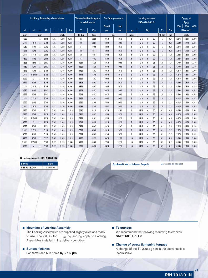
Locking Assembly dimensions Transmissible torques Surface pressure Locking screws DN min at
or axial forces ISO 4762-12.9 Rp0,2
Shaft Hub 200 300 400
d d x D L L1 L3 T Fax pW pN nSc DG TA Gw [N/mm2]
inch inch inch ft-lbs lbs psi pcs. ft-lbs lbs inch
1.000 1 x 1.969 1.457 1.220 0.854 323 7752 40170 15070 5 M 6 x 20 13 0.7 2.875 2.591 2.398
1.1875 1 3/16 x 2.165 1.457 1.220 0.854 385 7781 33800 13650 5 M 6 x 20 13 0.8 3.000 2.773 2.587
1.250 1 1/4 x 2.362 1.457 1.220 0.854 531 10195 38560 15070 6 M 6 x 20 13 0.9 3.375 3.108 2.876
1.375 1 3/8 x 2.362 1.457 1.220 0.854 585 10211 35055 15070 6 M 6 x 20 13 0.9 3.375 3.108 2.876
1.4375 1 7/16 x 2.559 1.457 1.220 0.854 620 10351 33495 13935 6 M 6 x 20 13 1.0 3.625 3.296 3.069
1.500 1 1/2 x 2.559 1.457 1.220 0.854 647 10352 32100 13935 6 M 6 x 20 13 1.0 3.625 3.296 3.069
1.625 1 5/8 x 2.953 1.811 1.496 0.996 1234 18225 43870 19055 6 M 8 x 25 30 1.7 4.750 4.202 3.796
1.750 1 3/4 x 2.953 1.811 1.496 0.996 1329 18226 40740 19055 6 M 8 x 25 30 1.7 4.750 4.202 3.796
1.875 1 7/8 x 3.150 1.811 1.496 0.996 1426 18253 38070 17915 6 M 8 x 25 30 1.8 4.875 4.381 3.986
1.9375 1 15/16 x 3.150 1.811 1.496 0.996 1473 18246 36840 17915 6 M 8 x 25 30 1.8 4.875 4.381 3.986
2.000 2 x 3.150 1.811 1.496 0.996 1521 18252 35690 17915 6 M 8 x 25 30 1.8 4.875 4.381 3.986
2.125 2 1/8 x 3.346 1.811 1.496 0.996 1803 20363 39125 19625 7 M 8 x 25 30 1.8 5.500 4.816 4.335
2.1875 2 3/16 x 3.346 1.811 1.496 0.996 1856 20363 38005 19625 7 M 8 x 25 30 1.8 5.500 4.816 4.335
2.250 2 1/4 x 3.543 1.811 1.496 0.996 1908 20352 36875 18485 7 M 8 x 25 30 1.9 5.500 4.984 4.518
2.375 2 3/8 x 3.543 1.811 1.496 0.996 2014 20352 34935 18485 7 M 8 x 25 30 1.9 5.500 4.984 4.518
2.4375 2 7/16 x 3.740 1.811 1.496 0.996 2466 24281 38965 20050 8 M 8 x 25 30 2.1 6.125 5.430 4.873
2.500 2 1/2 x 3.740 1.811 1.496 0.996 2530 24288 37990 20050 8 M 8 x 25 30 2.1 6.125 5.430 4.873
2.5625 2 9/16 x 3.740 1.811 1.496 0.996 2593 24286 37065 20050 8 M 8 x 25 30 2.1 6.125 5.430 4.873
2.750 2 3/4 x 4.331 2.362 1.969 1.315 3680 32116 34770 18200 7 M 10 x 35 61 4.6 6.750 6.058 5.502
2.875 2 7/8 x 4.528 2.362 1.969 1.315 3845 32097 33300 16920 7 M 10 x 35 61 4.9 6.875 6.176 5.653
2.9375 2 15/16 x 4.528 2.362 1.969 1.315 3929 32101 32590 16920 7 M 10 x 35 61 4.9 6.875 6.176 5.653
3.000 3 x 4.528 2.362 1.969 1.315 4012 32096 31910 16920 7 M 10 x 35 61 4.9 6.875 6.176 5.653
3.375 3 3/8 x 4.921 2.362 1.969 1.315 5434 38642 32430 18345 8 M 10 x 35 61 5.3 7.625 6.903 6.264
3.4375 3 7/16 x 5.118 2.362 1.969 1.315 5543 38700 31810 17630 8 M 10 x 35 61 5.7 7.875 7.079 6.451
3.500 3 1/2 x 5.118 2.362 1.969 1.315 5644 38702 31240 17630 8 M 10 x 35 61 5.7 7.875 7.079 6.451
3.750 3 3/4 x 5.315 2.362 1.969 1.315 7180 45952 36450 21190 10 M 10 x 35 61 6.0 9.000 7.899 7.036
3.9375 3 15/16 x 5.709 2.677 2.283 1.606 7957 48500 27300 16210 10 M 10 x 35 61 8.2 8.500 7.680 7.059
4.000 4 x 5.709 2.677 2.283 1.606 8083 48498 26870 16210 10 M 10 x 35 61 8.2 8.500 7.680 7.059
RfN 7013.0-IN
Mounting of Locking AssemblyThe Locking Assemblies are supplied slightly oiled and ready-to-use. The values for T, Fax, pW and pN apply to Locking Assemblies installed in the delivery condition.
Surface finishesFor shafts and hub bores Ra ≤ 1,6 µm
TolerancesWe recommend the following mounting tolerancesShaft: h8; Hub: H8
Change of screw tightening torquesA change of the TA-values given in the above table is inadmissible.
More sizes on requestExplanations to tables: Page 9Series Size
RfN 7013.0-IN 1 15/16
Ordering example: RfN 7013.0-IN
21

RINGFEDER® Locking Assemblies RfN 7013.0
LN ≥ 2 · L3
ø D
N
Characteristics
Excellent concentricity and very easy to dismantle – these Locking Assemblies provide particularly good concentricity bet-ween the clamped parts. The flange is reinforced at the critical point. This prevents a bending and lifting of the inner ring during installation and therefore a good dismantling is ensured.
High rotation speed – the Locking Assemblies remain true-to-form during assembly and so they are suitable in applications with higher rotational speeds.
High radial loads – the material strength of the RfN 7013 Lo-cking Assemblies makes them especially suitable for applications with high radial loads.
Example applications:
Crane running wheels, couplings, gear wheels, flywheels, fan wheels
L
L1
L3
d
D
Locking Assembly RfN 7013.0 · Dimensions
Locking Assembly RfN 7013.0 · Location / Calculation of hubs see on Page 92-93Calculation possible for other hub forms in our calculation program
Locking Assembly RfN 7013.0 · Gear wheels Calculation possible for other hub forms in our calculation program
22

Mounting of Locking AssemblyThe Locking Assemblies are supplied slightly oiled and ready-to-use. The values for T, Fax, pW and pN apply to Locking Assemblies installed in the delivery condition.
Surface finishesFor shafts and hub bores Ra ≤ 1,6 µm
TolerancesWe recommend the following mounting tolerancesShaft: h8; Hub: H8
Change of screw tightening torquesA change of the TA-values given in the above table is inadmissible.
More sizes on requestExplanations to tables: Page 9
RfN 7013.0
Series d D
RfN 7013.0 1.496 2.559
Ordering example: RfN 7013.0
Locking Assembly dimensions Transmissible torques Surface pressure Locking screws DN min at
or axial forces ISO 4762-12.9 Rp0,2
Shaft Hub 200 300 400
d x D d x D L L1 L3 T Fax pW pN nSc DG TA Gw [N/mm2] Tmax
mm inch inch ft-lbs lbs psi pcs. ft-lbs lbs inch ft-lbs
19 x 47 0.748 x 1.850 1.457 1.220 0.854 210 6744 43478 13043 4 M 6 x 20 13 0.64 2.756 2.402 2.244 236
20 x 47 0.787 x 1.850 1.457 1.220 0.854 221 6744 42029 13043 4 M 6 x 20 13 0.64 2.756 2.402 2.244 251
22 x 47 0.866 x 1.850 1.457 1.220 0.854 243 6744 37681 13043 4 M 6 x 20 13 0.6 2.756 2.402 2.244 272
24 x 50 0.945 x 1.969 1.457 1.220 0.854 310 8992 43478 15942 5 M 6 x 20 13 0.68 3.150 2.677 2.480 354
25 x 50 0.984 x 1.969 1.457 1.220 0.854 325 8992 42029 15942 5 M 6 x 20 13 0.66 3.150 2.677 2.480 369
28 x 55 1.102 x 2.165 1.457 1.220 0.854 361 8992 37681 14493 5 M 6 x 20 13 0.79 3.268 2.835 2.677 413
30 x 55 1.181 x 2.165 1.457 1.220 0.854 391 8992 34783 14493 5 M 6 x 20 13 0.75 3.268 2.835 2.677 443
32 x 60 1.260 x 2.362 1.457 1.220 0.854 546 11241 39130 15942 6 M 6 x 20 13 0.9 3.740 3.189 2.953 627
35 x 60 1.378 x 2.362 1.457 1.220 0.854 597 11241 36232 15942 6 M 6 x 20 13 0.84 3.740 3.189 2.953 686
38 x 65 1.496 x 2.559 1.457 1.220 0.854 656 11241 33333 14493 6 M 6 x 20 13 0.97 3.898 3.386 3.150 752
40 x 65 1.575 x 2.559 1.457 1.220 0.854 693 11241 31884 14493 6 M 6 x 20 13 0.9 3.898 3.386 3.150 797
42 x 75 1.654 x 2.953 1.811 1.496 0.996 1276 17985 43478 18841 6 M 8 x 25 30 1.7 5.394 4.331 3.937 1460
45 x 75 1.772 x 2.953 1.811 1.496 0.996 1372 17985 42029 18841 6 M 8 x 25 30 1.5 5.394 4.331 3.937 1571
48 x 80 1.890 x 3.150 1.811 1.496 0.996 1460 17985 39130 18841 6 M 8 x 25 30 1.8 5.512 4.488 4.134 1674
50 x 80 1.969 x 3.150 1.811 1.496 0.996 1527 17985 37681 18841 6 M 8 x 25 30 1.7 5.512 4.488 4.134 1755
55 x 85 2.165 x 3.346 1.811 1.496 0.996 1873 20233 39130 20290 7 M 8 x 25 30 1.8 6.260 4.961 4.488 2154
60 x 90 2.362 x 3.543 1.811 1.496 0.996 2043 20233 36232 18841 7 M 8 x 25 30 1.9 6.339 5.118 4.646 2345
65 x 95 2.559 x 3.740 1.811 1.496 0.996 2641 24729 37681 20290 8 M 8 x 25 30 2.1 7.126 5.591 5.039 3031
70 x 110 2.756 x 4.331 2.362 1.969 1.315 3762 31473 34783 18841 7 M 10 x 35 61 4.6 7.677 6.220 5.669 4322
75 x 115 2.953 x 4.528 2.362 1.969 1.315 4027 31473 33333 17391 7 M 10 x 35 61 4.9 7.638 6.339 5.827 4625
80 x 120 3.150 x 4.724 2.362 1.969 1.315 4315 31473 30435 15942 7 M 10 x 35 61 5.1 7.677 6.457 5.984 4956
85 x 125 3.346 x 4.921 2.362 1.969 1.315 5495 40466 33333 18841 8 M 10 x 35 61 5.3 8.740 7.087 6.457 6314
90 x 130 3.543 x 5.118 2.362 1.969 1.315 5827 40466 31884 17391 8 M 10 x 35 61 5.7 8.858 7.244 6.614 6697
95 x 135 3.740 x 5.315 2.362 1.969 1.315 7302 47210 37681 21739 10 M 10 x 35 61 6.0 10.591 8.150 7.283 8394
100 x 145 3.937 x 5.709 2.677 2.283 1.606 8113 49458 27536 15942 10 M 10 x 35 61 8.2 9.370 7.835 7.244 9330
110 x 155 4.331 x 6.102 2.677 2.283 1.606 8925 49458 26087 15942 10 M 10 x 35 61 8.8 9.685 8.228 7.638 10260
120 x 165 4.724 x 6.496 2.677 2.283 1.606 11580 58451 27536 17391 12 M 10 x 35 61 9.5 10.984 9.094 8.346 13313
130 x 180 5.118 x 7.087 3.031 2.559 1.787 15268 71939 27536 17391 10 M 12 x 40 107 13 12.008 9.921 9.094 17554
140 x 190 5.512 x 7.480 3.031 2.559 1.787 16595 71939 26087 15942 10 M 12 x 40 107 14 12.283 10.276 9.488 19081
150 x 200 5.906 x 7.874 3.031 2.559 1.787 21021 85428 28986 18841 12 M 12 x 40 107 15 14.055 11.339 10.315 24170
23

RINGFEDER® Locking Assemblies RfN 7013.1-IN
LN ≥ 2 · L3
ø D
N
Ld
D
L1
L4
DB
1
L3
Locking Assembly RfN 7013.1 · Location / Calculation of hubs see on Page 92-93Calculation possible for other hub forms in our calculation program
Locking Assembly RfN 7013.1 · Bevel gear wheel
Locking Assembly RfN 7013.1 · Dimensions
Characteristics
Excellent concentricity and very easy to dismantle – these Locking Assemblies provide particularly good concentricity bet-ween the clamped parts. The flange is reinforced at the critical point, preventing bending or lifting of the inner ring during assem-bly and thereby ensuring easy dismantling.
High rotation speed – the dimensional accuracy of the RfN 7013 Locking Assemblies allows their use in applications with higher rotational speeds.
High radial loads – the material strength of the RfN 7013 Locking Assemblies makes them especially suitable for applications with high radial loads.
Axial hub positioning – the increased outer diameter of the flange prevents the axial movement of the hub during assembly and improves the run-out ability of the Locking Assembly.
High torque – the increased number of clamping screws ensures the same transmission values as the RfN 7013.0.
24

Locking Assembly dimensions Transmissible torques Surface pressure Locking screws min. DN
or axial forces ISO 4762-12.9 Rp0,2 [N/mm2]
Shaft Hub
d d x D DB1 L L1 L3 L4 T Fax pW pN nSc DG SW TA 200 300 400 Gw
inch inch inch inch ft-lbs lbs psi pcs. mm ft-lbs inch lbs
1.000 1 x 1.969 2.205 1.457 1.220 0.854 1.012 323 7752 40170 15070 7 M 6 x 20 5 13 2.875 2.591 2.398 0.7
1.500 1 1/2 x 2.559 2.874 1.457 1.220 0.854 1.012 647 10352 32100 13935 10 M 6 x 20 5 13 3.625 3.296 3.069 1.0
1.250 1 1/4 x 2.362 2.677 1.457 1.220 0.854 1.012 531 10195 38560 15070 9 M 6 x 20 5 13 3.375 3.108 2.876 0.9
1.9375 1 15/16 x 3.150 3.465 1.811 1.496 0.996 1.193 1473 18246 36840 17915 9 M 8 x 25 6 30 4.875 4.381 3.986 1.8
1.1875 1 3/16 x 2.165 2.441 1.457 1.220 0.854 1.012 385 7781 33800 13650 7 M 6 x 20 5 13 3.000 2.773 2.587 0.8
1.750 1 3/4 x 2.953 3.268 1.811 1.496 0.996 1.193 1329 18226 40740 19055 9 M 8 x 25 6 30 4.750 4.202 3.796 1.7
1.375 1 3/8 x 2.362 2.677 1.457 1.220 0.854 1.012 585 10211 35055 15070 9 M 6 x 20 5 13 3.375 3.108 2.876 0.9
1.4375 1 4/9 x 2.559 2.874 1.457 1.220 0.854 1.012 620 10351 33495 13935 10 M 6 x 20 5 13 3.625 3.296 3.069 1.0
1.625 1 5/8 x 2.953 3.268 1.811 1.496 0.996 1.193 1234 18225 43870 19055 9 M 8 x 25 6 30 4.750 4.202 3.796 1.7
1.875 1 7/8 x 3.150 3.465 1.811 1.496 0.996 1.193 1426 18253 38070 17915 9 M 8 x 25 6 30 4.875 4.381 3.986 1.8
2.000 2 x 3.150 3.465 1.811 1.496 0.996 1.193 1521 18252 35690 17915 9 M 8 x 25 6 30 4.875 4.381 3.986 1.8
2.500 2 1/2 x 3.740 4.134 1.811 1.496 0.996 1.193 2530 24288 37990 20050 12 M 8 x 25 6 30 6.125 5.430 4.873 2.1
2.250 2 1/4 x 3.543 3.937 1.811 1.496 0.996 1.193 1908 20352 36875 18485 10 M 8 x 25 6 30 5.500 4.984 4.518 1.9
2.125 2 1/8 x 3.346 3.740 1.811 1.496 0.996 1.193 1803 20363 39125 19625 10 M 8 x 25 6 30 5.500 4.816 4.335 1.8
2.9375 2 15/16 x 4.528 4.921 2.362 1.969 1.315 1.591 3929 32101 32590 16920 10 M 10 x 35 8 61 6.875 6.176 5.653 4.9
2.1875 2 3/16 x 3.346 3.740 1.811 1.496 0.996 1.193 1856 20363 38005 19625 10 M 8 x 25 6 30 5.500 4.816 4.335 1.8
2.750 2 3/4 x 4.331 4.724 2.362 1.969 1.315 1.591 3680 32116 34770 18200 10 M 10 x 35 8 61 6.750 6.058 5.502 4.6
2.375 2 3/8 x 3.543 3.937 1.811 1.496 0.996 1.193 2014 20352 34935 18485 10 M 8 x 25 6 30 5.500 4.984 4.518 1.9
2.5625 2 4/7 x 3.740 4.134 1.811 1.496 0.996 1.193 2593 24286 37065 20050 12 M 8 x 25 6 30 6.125 5.430 4.873 2.1
2.4375 2 7/16 x 3.740 4.134 1.811 1.496 0.996 1.193 2466 24281 38965 20050 12 M 8 x 25 6 30 6.125 5.430 4.873 2.1
2.875 2 7/8 x 4.528 4.921 2.362 1.969 1.315 1.591 3845 32097 33300 16920 10 M 10 x 35 8 61 6.875 6.176 5.653 4.9
3.000 3 x 4.528 4.921 2.362 1.969 1.315 1.591 4012 32096 31910 16920 10 M 10 x 35 8 61 6.875 6.176 5.653 4.9
3.500 3 1/2 x 5.118 5.512 2.362 1.969 1.315 1.591 5644 38702 31240 17630 12 M 10 x 35 8 61 7.875 7.079 6.451 5.7
3.9375 3 15/16 x 5.709 6.102 2.677 2.283 1.606 1.882 7957 48500 27300 16210 15 M 10 x 35 8 61 8.500 7.680 7.059 8.2
3.750 3 3/4 x 5.315 5.709 2.362 1.969 1.315 1.591 7180 45952 36450 21190 15 M 10 x 35 8 61 9.000 7.899 7.036 6.0
3.375 3 3/8 x 4.921 5.315 2.362 1.969 1.315 1.591 5434 38642 32430 18345 12 M 10 x 35 8 61 7.625 6.903 6.264 5.3
3.4375 3 4/9 x 5.118 5.512 2.362 1.969 1.315 1.591 5543 38700 31810 17630 12 M 10 x 35 8 61 7.875 7.079 6.451 5.7
4.000 4 x 5.709 6.102 2.677 2.283 1.606 1.882 8083 48498 26870 16210 15 M 10 x 35 8 61 8.500 7.680 7.059 8.2
RfN 7013.1-IN
Mounting of Locking AssemblyThe Locking Assemblies are supplied slightly oiled and ready-to-use. The values for T, Fax, pW and pN apply to Locking Assemblies installed in the delivery condition.
Surface finishesFor shafts and hub bores Ra ≤ 1,6 µm
TolerancesWe recommend the following mounting tolerancesShaft: h8; Hub: H8
Arrangement of several Locking Assemblies RfN 7013.1Arrangement only possible from 2 sides. If several Locking Assemblies are used to increase the transmission values, the clamping systematization has to be considered.
Change of screw tightening torquesA change of the TA-values given in the above table is not admissible.
More sizes on requestExplanations to tables: Page 9Series Size
RfN 7013.1-IN 1 7/8
Ordering example: RfN 7013.1-IN
25

RINGFEDER® Locking Assemblies RfN 7013.1
LN ≥ 2 · L3
ø D
N
Ld
D
L1
L4
DB
1
L3
Locking Assembly RfN 7013.1 · Location / Calculation of hubs see on Page 92-93Calculation possible for other hub forms in our calculation program
Locking Assembly RfN 7013.1 · Bevel gear wheel
Locking Assembly RfN 7013.1 · Dimensions
Characteristics
Excellent concentricity and very easy to dismantle – these Locking Assemblies provide particularly good concentricity bet-ween the clamped parts. The flange is reinforced at the critical point, preventing bending or lifting of the inner ring during assem-bly and thereby ensuring easy dismantling.
High rotation speed – the dimensional accuracy of the RfN 7013 Locking Assemblies allows their use in applications with higher rotational speeds.
High radial loads – the material strength of the RfN 7013 Locking Assemblies makes them especially suitable for applications with high radial loads.
Axial hub positioning – the increased outer diameter of the flange prevents the axial movement of the hub during assemblyand improves the run-out ability of the Locking Assembly.
High torque – the increased number of clamping screws ensures the same transmission values as the RfN 7013.0.
26

Locking Assembly dimensions Transmissible torques Surface pressure Locking screws DN min at
or axial forces ISO 4762-12.9 Rp0,2
Shaft Hub 200 300 400
d x D d x D DB1 L L1 L3 L4 T Fax pW pN nSc DG TA Gw [N/mm2] Tmax
mm inch inch inch ft-lbs lbs psi pcs. ft-lbs lbs inch ft-lbs
19 x 47 0.748 x 1.85 2.087 1.457 1.220 0.854 1.012 210 6744 43478 13043 6 M 6 x 20 13 0.64 2.756 2.402 2.244 229
20 x 47 0.787 x 1.85 2.087 1.457 1.220 0.854 1.012 221 6744 42029 13043 6 M 6 x 20 13 0.64 2.756 2.402 2.244 243
22 x 47 0.866 x 1.85 2.087 1.457 1.220 0.854 1.012 243 6744 37681 13043 6 M 6 x 20 13 0.6 2.756 2.402 2.244 266
24 x 50 0.945 x 1.969 2.205 1.457 1.220 0.854 1.012 310 8992 43478 15942 7 M 6 x 20 13 0.7 3.150 2.677 2.480 339
25 x 50 0.984 x 1.969 2.205 1.457 1.220 0.854 1.012 325 8992 42029 15942 7 M 6 x 20 13 0.7 3.150 2.677 2.480 354
28 x 55 1.102 x 2.165 2.441 1.457 1.220 0.854 1.012 361 8992 37681 14493 7 M 6 x 20 13 0.8 3.268 2.835 2.677 391
30 x 55 1.181 x 2.165 2.441 1.457 1.220 0.854 1.012 391 8992 34783 14493 7 M 6 x 20 13 0.75 3.268 2.835 2.677 428
32 x 60 1.260 x 2.362 2.677 1.457 1.220 0.854 1.012 546 11241 39130 15942 9 M 6 x 20 13 0.9 3.740 3.189 2.953 597
35 x 60 1.378 x 2.362 2.677 1.457 1.220 0.854 1.012 597 11241 36232 15942 9 M 6 x 20 13 0.84 3.740 3.189 2.953 656
38 x 65 1.496 x 2.559 2.874 1.457 1.220 0.854 1.012 656 11241 33333 14493 10 M 6 x 20 13 1.0 3.898 3.386 3.150 715
40 x 65 1.575 x 2.559 2.874 1.457 1.220 0.854 1.012 693 11241 31884 14493 10 M 6 x 20 13 0.9 3.898 3.386 3.150 760
42 x 75 1.654 x 2.953 3.268 1.811 1.496 0.996 1.193 1276 17985 43478 18841 9 M 8 x 25 30 1.7 5.394 4.331 3.937 1401
45 x 75 1.772 x 2.953 3.268 1.811 1.496 0.996 1.193 1372 17985 40580 18841 9 M 8 x 25 30 1.5 5.394 4.331 3.937 1505
48 x 80 1.890 x 3.150 3.465 1.811 1.496 0.996 1.193 1460 17985 39130 18841 9 M 8 x 25 30 1.8 5.512 4.488 4.134 1601
50 x 80 1.969 x 3.150 3.465 1.811 1.496 0.996 1.193 1527 17985 37681 18841 9 M 8 x 25 30 1.7 5.512 4.488 4.134 1674
55 x 85 2.165 x 3.346 3.740 1.811 1.496 0.996 1.193 1873 20233 39130 20290 10 M 8 x 25 30 1.8 6.260 4.961 4.488 2058
60 x 90 2.362 x 3.543 3.937 1.811 1.496 0.996 1.193 2043 20233 36232 18841 10 M 8 x 25 30 1.9 6.339 5.118 4.646 2242
65 x 95 2.559 x 3.740 4.134 1.811 1.496 0.996 1.193 2641 24729 37681 20290 12 M 8 x 25 30 2.1 7.126 5.591 5.039 2899
70 x 110 2.756 x 4.331 4.724 2.362 1.969 1.315 1.591 3762 31473 34783 18841 10 M 10 x 35 61 4.6 7.677 6.220 5.669 4138
75 x 115 2.953 x 4.528 4.921 2.362 1.969 1.315 1.591 4027 31473 33333 17391 10 M 10 x 35 61 4.9 7.638 6.339 5.827 4425
80 x 120 3.150 x 4.724 5.118 2.362 1.969 1.315 1.591 4315 31473 30435 15942 10 M 10 x 35 61 5.1 7.677 6.457 5.984 4743
85 x 125 3.346 x 4.921 5.315 2.362 1.969 1.315 1.591 5495 40466 33333 18841 12 M 10 x 35 61 5.3 8.740 7.087 6.457 6041
90 x 130 3.543 x 5.118 5.512 2.362 1.969 1.315 1.591 5827 40466 31884 17391 12 M 10 x 35 61 5.7 8.858 7.244 6.614 6409
95 x 135 3.740 x 5.315 5.709 2.362 1.969 1.315 1.591 7302 47210 37681 21739 15 M 10 x 35 61 6.0 10.591 8.150 7.283 8032
100 x 145 3.937 x 5.709 6.102 2.677 2.283 1.606 1.882 8113 49458 27536 15942 15 M 10 x 35 61 8.2 9.370 7.835 7.244 8925
110 x 155 4.331 x 6.102 6.496 2.677 2.283 1.606 1.882 8925 49458 26087 15942 15 M 10 x 35 61 8.8 9.685 8.228 7.638 9817
120 x 165 4.724 x 6.496 6.890 2.677 2.283 1.606 1.882 11580 58451 27536 17391 18 M 10 x 35 61 9.5 10.984 9.094 8.346 12738
130 x 180 5.118 x 7.087 7.480 3.031 2.559 1.787 2.063 15268 71939 27536 17391 15 M 12 x 40 107 13 12.008 9.921 9.094 16795
140 x 190 5.512 x 7.480 7.874 3.031 2.559 1.787 2.063 16595 71939 26087 15942 15 M 12 x 40 107 14 12.283 10.276 9.488 18255
150 x 200 5.906 x 7.874 8.268 3.031 2.559 1.787 2.063 21021 85428 28986 18841 18 M 12 x 40 107 15 14.055 11.339 10.315 23123
RfN 7013.1
Mounting of Locking AssemblyThe Locking Assemblies are supplied slightly oiled and ready-to-use. The values for T, Fax, pW and pN apply to Locking Assemblies installed in the delivery condition.
Surface finishesFor shafts and hub bores Ra ≤ 1,6 µm
TolerancesWe recommend the following mounting tolerancesShaft: h8; Hub: H8
Arrangement of several Locking Assemblies RfN 7013.1Arrangement only possible from 2 sides. If several Locking Assemblies are used to increase the transmission values, the clamping systematization has to be considered.
Change of screw tightening torquesA change of the TA-values given in the above table is not admissible.
More sizes on requestExplanations to tables: Page 9Series d D
RfN 7013.1 1.378 2.362
Ordering example: RfN 7013.1
27

RINGFEDER® Locking Assemblies RfN 7014
LN ≥ L1 + 2 · (L - L1)
ø D
N
L
L1
D
d
L3
Locking Assembly RfN 7014 · Location / Calculation of hubs see on Page 92-93 Calculation possible for other hub forms in our calculation program
Locking Assembly RfN 7014 · Gear wheel fastening
Locking Assembly RfN 7014 · Dimensions
Characteristics
Large transmittable peripheral forces – due to the long, flat cones it is possible to transmit maximum torques and axial forces with one Locking Assembly RfN 7014.
Maximum reliability – due to the flat cones and the relatively wide construction (large guide lengths) the Locking Assemblies RfN 7014 centre themselves. During installation the Locking Assembly, shaft and hub remain in position to one another. The shaft and hub are loaded by pressure, providing additional safety compared to 3-part versions.
Example applications:
Heavy pulleys, construction of heavy machinery, couplings, cable sheaves
28

Mounting of Locking AssemblyThe values for T, Fax, pW and pN apply to Locking Assemblies installed in oiled condition.
Surface finishesFor shafts and hub bores Ra ≤ 3,2 µm
TolerancesWe recommend the following mounting tolerancesShaft: k9-h9; Hub: N9-H9
Arrangement of several Locking Assemblies RfN 7014Max. two RfN 7014 Locking Assemblies can be used in series, the trans missible torques and axial forces are added.
Pay attention: For the removal of the Locking Assembly a step in the hub or shaft is required (see location drawing page 22).
Change of screw tightening torquesA reduction of the contact pressures and the transmission va-lues by reducing the tightening torque of the screws is possi-ble. The admissible lower limit results from the multiplication of the TA-values of the above table by 0.8. There is an approxi-mate linear relationship between T, TA, Fax, pW and pN.
RfN 7014
More sizes on requestExplanations to tables: Page 9Series d D
RfN 7014 4.724 0.186
Ordering example: RfN 7014
Locking Assembly dimensions Transmissible torques Surface pressure Locking screws DN min at
or axial forces ISO 4762-12.9 Rp0,2
Shaft Hub 200 300 400
d x D d x D L L1 L3 T Fax pW pN nSc DG TA Gw [N/mm2] Tmax
mm inch inch ft-lbs lbs psi pcs. ft-lbs lbs inch ft-lbs
70 x 120 2.756 x 0.109 2.913 2.441 2.205 5052 44063 28986 16957 8 M 12 x 55 107 7.3 7.756 6.496 6.063 5951
80 x 130 3.150 x 0.124 2.913 2.441 2.205 8593 65420 38116 23478 12 M 12 x 55 107 8.2 9.054 8.465 7.441 10188
90 x 140 3.543 x 0.140 2.913 2.441 2.205 9588 64970 33913 21739 12 M 12 x 55 107 8.8 12.205 8.661 7.717 11436
100 x 160 3.937 x 0.155 3.701 3.150 2.913 14530 88575 30870 19275 12 M 14 x 70 170 15.9 12.283 9.409 8.543 17421
110 x 170 4.331 x 0.171 3.701 3.150 2.913 19619 108808 35072 22754 14 M 14 x 70 170 17 11.841 11.181 9.764 23635
120 x 180 4.724 x 0.186 3.701 3.150 2.913 21316 108358 32174 21449 15 M 14 x 70 170 18.3 16.378 11.299 10.039 25791
130 x 190 5.118 x 0.202 3.701 3.150 2.913 23012 107909 29710 20290 15 M 14 x 70 170 19.4 15.709 11.496 10.354 27956
140 x 200 5.512 x 0.217 3.701 3.150 2.913 29650 129041 32899 23043 17 M 14 x 70 170 20.5 13.930 13.268 11.575 36154
150 x 210 5.906 x 0.233 3.701 3.150 2.913 31642 128591 30725 21884 18 M 14 x 70 170 22 20.079 13.386 11.850 38714
160 x 230 6.299 x 0.248 4.331 3.701 3.465 47205 179848 32899 22899 17 M 16 x 80 262 32.8 16.019 15.354 13.346 57942
170 x 240 6.693 x 0.264 4.331 3.701 3.465 50007 179398 31014 22029 18 M 16 x 80 262 34.6 16.013 15.512 13.661 61570
180 x 250 7.087 x 0.279 4.331 3.701 3.465 61218 207275 34058 24493 20 M 16 x 80 262 36.2 18.214 17.835 15.118 75589
190 x 260 7.480 x 0.295 4.331 3.701 3.465 64906 208174 32319 23623 21 M 16 x 80 262 37.9 18.109 17.874 15.354 80356
200 x 270 7.874 x 0.310 4.331 3.701 3.465 77445 236051 35072 25942 23 M 16 x 80 262 41.4 20.623 20.630 16.969 96128
220 x 300 8.661 x 0.341 5.276 4.567 4.331 90721 251338 27391 20145 21 M 18 x 100 358 61.1 26.063 18.504 16.535 113146
240 x 320 9.449 x 0.372 5.276 4.567 4.331 112849 286633 28696 21449 24 M 18 x 100 358 65.7 21.350 20.748 18.228 141356
260 x 340 10.236 x 0.403 5.276 4.567 4.331 137188 321703 29710 22754 26 M 18 x 100 358 70.5 23.682 23.071 19.921 172533
280 x 370 11.024 x 0.434 6.142 5.354 5.118 169642 369363 27826 21014 24 M 20 x 120 509 101.4 24.687 23.858 20.984 214138
300 x 390 11.811 x 0.465 6.142 5.354 5.118 180705 367115 25942 20000 24 M 20 x 120 509 108 34.409 24.173 21.575 228894
29

RINGFEDER® Locking Assemblies RfN 7015.0
LN ≥ L + 2 · (L - L1)
ø D
N
Locking Assembly RfN 7015.0 · Location / Calculation of hubs see on Page 92 - 93Calculation possible for other hub forms in our calculation program
Drive unit for high-speed elevatorwith Locking Assembly
L
L1
d
D
L3
Locking Assembly RfN 7015 · Dimensions
Characteristics
Precision Locking Assembly for the transmission of maximum torques and axial forces with special demands on the concentricity of the parts of the clamped, as well as for applications subjected to bending moments.
Large transmittable peripheral forces – due to the long, flat cones it is possible to transmit maximum torques and axial forces with one RfN 7015.0 Locking Assembly. During installation the Locking As-sembly, shaft and hub remain in position to one another. Compared to 3-part versions, thus an additional safety is provided. Shaft and hub are only compression-loaded.
Bending moment and radial loads – combined loads can be trans-mitted (Please contact our technical department for assistance).
Excellent centering ability – with a relatively wide design and the precentering web the RfN 7015.0 Locking Assembly has excellent centering ability.
Example applications:
Belt drums, crusher rotors, press drives
30

Locking Assembly dimensions Transmissible torques Surface pressure Locking screws DN min at
or axial forces ISO 4762-12.9 Rp0,2
Shaft Hub 200 300 400
d x D d x D L L1 L3 T Fax pW pN nSc DG TA Gw [N/mm2] Tmax
mm inch inch ft-lbs lbs psi pcs. ft-lbs lbs inch ft-lbs
100 x 145 3.937 x 5.709 3.031 2.559 2.362 10506 64071 28696 19710 10 M 12 x 55 107 9 11.299 8.583 7.795 12359
110 x 155 4.331 x 6.102 3.031 2.559 2.362 11556 64071 26087 18406 10 M 12 x 55 107 9.7 11.142 8.858 8.110 13596
120 x 165 4.724 x 6.496 3.031 2.559 2.362 15128 76885 28696 20870 12 M 12 x 55 107 10.6 13.937 10.079 9.055 17798
130 x 180 5.118 x 7.087 3.386 2.913 2.677 20486 95994 28551 20580 15 M 12 x 60 107 14.3 15.354 11.024 9.882 24101
140 x 190 5.512 x 7.480 3.386 2.913 2.677 26474 115328 31884 23478 18 M 12 x 60 107 15.4 13.233 12.874 11.142 31146
150 x 200 5.906 x 7.874 3.386 2.913 2.677 28366 115328 29710 22319 18 M 12 x 60 107 16.3 13.344 12.953 11.378 33371
160 x 210 6.299 x 8.268 3.386 2.913 2.677 35299 134436 32464 24783 21 M 12 x 60 107 17.2 15.300 14.961 12.677 41528
170 x 225 6.693 x 8.858 3.740 3.189 2.953 43974 157592 32174 24348 18 M 14 x 65 170 22 15.671 15.709 13.425 51734
180 x 235 7.087 x 9.252 3.740 3.189 2.953 46561 157592 30435 23333 18 M 14 x 65 170 23.4 16.368 15.748 13.661 54777
190 x 250 7.480 x 9.843 4.252 3.701 3.465 54608 175127 26957 20435 20 M 14 x 75 170 31.5 22.126 15.512 13.858 64245
200 x 260 7.874 x 10.236 4.252 3.701 3.465 68979 210197 30580 23623 24 M 14 x 75 170 33.1 18.109 18.150 15.512 81152
220 x 285 8.661 x 11.220 4.724 4.094 3.858 77899 215818 27391 21159 18 M 16 x 90 262 43.7 27.283 18.189 16.063 91646
240 x 305 9.449 x 12.008 4.724 4.094 3.858 113309 287757 33478 26377 24 M 16 x 90 262 47.2 23.297 24.449 19.646 133304
260 x 325 10.236 x 12.795 4.724 4.094 3.858 127865 299897 32174 25797 25 M 16 x 90 262 50.7 23.677 25.236 20.591 150430
280 x 355 11.024 x 13.976 5.669 4.961 4.724 159684 347556 28986 22899 24 M 18 x 110 358 77.6 23.685 24.646 21.102 187863
300 x 375 11.811 x 14.764 5.669 4.961 4.724 178219 362169 28261 22609 25 M 18 x 110 358 82.5 25.021 25.669 22.087 209669
320 x 405 12.598 x 15.945 6.378 5.591 5.315 245860 468279 28841 22754 25 M 20 x 120 509 113.1 27.022 27.992 23.976 289247
340 x 425 13.386 x 16.732 6.378 5.591 5.315 261226 468279 27101 21739 25 M 20 x 120 509 119.3 27.210 28.110 24.528 307325
360 x 455 14.173 x 17.913 7.362 6.496 6.220 341726 578661 26957 21304 25 M 22 x 130 686 166.2 29.131 29.961 26.181 402031
380 x 475 14.961 x 18.701 7.362 6.496 6.220 360711 578661 25507 20435 25 M 22 x 130 686 174.2 45.236 30.236 26.732 424366
400 x 495 15.748 x 19.488 7.362 6.496 6.220 379695 578661 24203 19565 25 M 22 x 130 686 182.5 43.307 30.591 27.323 446701
420 x 515 16.535 x 20.276 7.362 6.496 6.220 478416 694438 27681 22609 30 M 22 x 130 686 190.7 34.362 35.709 30.591 562843
440 x 545 17.323 x 21.457 8.031 7.087 6.772 589783 817184 27826 22464 30 M 24 x 150 885 242.5 34.894 37.559 32.244 693862
460 x 565 18.110 x 22.244 8.031 7.087 6.772 616591 817184 26667 21739 30 M 24 x 150 885 251.3 36.174 37.677 32.756 725401
480 x 585 18.898 x 23.031 8.031 7.087 6.772 686293 871589 27246 22319 32 M 24 x 150 885 262.3 37.454 40.079 34.488 807403
500 x 605 19.685 x 23.819 8.031 7.087 6.772 714889 871589 26232 21594 32 M 24 x 150 885 271.2 38.735 40.236 35.000 841045
520 x 630 20.472 x 24.803 8.937 7.874 7.480 831290 974552 25072 20725 30 M 27 x 160 1180 326.3 60.906 40.276 35.551 977988
540 x 650 21.260 x 25.591 8.937 7.874 7.480 863262 974552 24203 20145 30 M 27 x 160 1180 339.5 58.661 40.591 36.142 1015603
560 x 670 22.047 x 26.378 8.937 7.874 7.480 895235 974552 23333 19565 30 M 27 x 160 1180 352.7 57.126 40.984 36.732 1053217
580 x 690 22.835 x 27.165 8.937 7.874 7.480 927208 974552 22464 18986 30 M 27 x 160 1180 363.8 56.063 41.457 37.362 1090833
600 x 710 23.622 x 27.953 8.937 7.874 7.480 1023126 1039522 23188 19565 32 M 27 x 160 1180 374.8 61.220 43.622 39.055 1203678
620 x 730 24.409 x 28.740 8.937 7.874 7.480 1057230 1039522 22464 19130 32 M 27 x 160 1180 390.2 60.079 44.055 39.685 1243801
640 x 750 25.197 x 29.528 8.937 7.874 7.480 1193647 1136864 23768 20290 35 M 27 x 160 1180 401.2 69.252 47.205 41.890 1404290
660 x 770 25.984 x 30.315 8.937 7.874 7.480 1230949 1136864 23043 19855 35 M 27 x 160 1180 412.3 67.441 47.598 42.520 1448175
680 x 790 26.772 x 31.102 8.937 7.874 7.480 1304486 1169462 23043 19855 36 M 27 x 160 1180 425.5 69.528 48.898 43.661 1534689
700 x 810 27.559 x 31.890 8.937 7.874 7.480 1342853 1169462 22464 19420 36 M 27 x 160 1180 436.5 68.189 49.331 44.291 1579827
720 x 830 28.346 x 32.677 8.937 7.874 7.480 1534669 1299395 24239 21046 40 M 27 x 160 1180 449.7 --- 53.504 47.087 1805492
740 x 850 29.134 x 33.465 8.937 7.874 7.480 1577299 1299395 23513 20465 40 M 27 x 160 1180 460.8 79.921 53.819 47.677 1855645
760 x 870 29.921 x 34.252 8.937 7.874 7.480 1619928 1299395 22933 20030 40 M 27 x 160 1180 474.0 77.913 54.173 48.268 1905798
780 x 890 30.709 x 35.039 8.937 7.874 7.480 1662558 1299395 22352 19595 40 M 27 x 160 1180 485.0 76.378 54.567 48.898 1955950
800 x 910 31.496 x 35.827 8.937 7.874 7.480 1790447 1364365 22933 20175 42 M 27 x 160 1180 496.0 82.126 56.811 50.591 2106408
Mounting of Locking AssemblyThe values for T, Fax, pW and pN apply to Locking Assemblies installed in oiled condition.
Surface finishesFor shafts and hub bores Ra ≤ 3,2 µm
TolerancesWe recommend the following mounting tolerancesShaft: h8 · Hub: H8
Arrangement of several Locking Assemblies RfN 7015.0Max. two RfN 7015 Locking Assemblies can be used in series, the trans missible torques and axial forces are added.
Change of screw tightening torquesA reduction of the contact pressures and the transmission values by reducing the tightening torque of the screws is pos-sible. The admissible lower limit results from the multiplication of the TA-values of the above table by 0.5. There is an approxi-mate linear relationship between T, TA , Fax, pW and pN.
RfN 7015.0
More sizes on requestExplanations to tables: Page 9Series d D
RfN 7015.0 17.323 21.457
Ordering example: RfN 7015.0
31

RINGFEDER® Locking Assemblies RfN 7015.1
LN ≥ L + 2 · (L - L1)
ø D
N
Locking Assembly RfN 7015.1 · Location / Calculation of hubs see on Page 92-93Calculation possible for other hub forms in our calculation program
Jaw crusher
L
L1
d
D
L3
Locking Assembly RfN 7015.1 · Dimensions
Characteristics
Locking Assembly for transmission of torques, axial forces and high bending moments at reduced contact pressures, with special requirements to the true running of the clamped pieces.
Special featuresWith the long and flat angle of the cones, the required loads can be transferred with one Locking Assembly RfN 7015.1. During moun-ting Locking Assembly, shaft and hub remain to each other in posi-tion. Compared to three-part construction types, thus an additional safety is provided. Shaft and hub are only compression loaded.
Bending moment and radial loads – combined loads can be transmitted (Please contact our technical department for assistance).
Excellent centering ability – with a relatively wide design and the precentering web the RfN 7015.1 Locking Assembly has excellent centering ability.
Example applications:
Belt drums, gear wheels
32

Locking Assembly dimensions Transmissible torques Surface pressure Locking screws DN min at
or axial forces ISO 4762-12.9 Rp0,2
Shaft Hub 200 300 400
d x D d x D L L1 L3 T Fax pW pN nSc DG TA Gw [N/mm2] Tmax
mm inch inch ft-lbs lbs psi pcs. ft-lbs lbs inch ft-lbs
100 x 145 3.937 x 5.709 2.953 2.559 2.362 4850 29675 13188 9130 9 M 10 x 55 61 9 7.244 6.732 6.535 5706
110 x 155 4.331 x 6.102 2.953 2.559 2.362 5928 32822 13333 9420 10 M 10 x 55 61 10 7.835 7.244 7.008 6974
120 x 165 4.724 x 6.496 2.953 2.559 2.362 7760 39342 14638 10725 12 M 10 x 55 61 11 8.661 7.913 7.598 9129
130 x 180 5.118 x 7.087 3.307 2.913 2.677 10508 49233 14638 10580 15 M 10 x 60 61 14 9.449 8.622 8.307 12362
140 x 190 5.512 x 7.480 3.307 2.913 2.677 11317 49233 13623 10000 15 M 10 x 60 61 15 9.764 9.016 8.701 13313
150 x 200 5.906 x 7.874 3.307 2.913 2.677 12933 52606 13623 10145 16 M 10 x 60 61 16 10.354 9.528 9.173 15215
160 x 210 6.299 x 8.268 3.307 2.913 2.677 15519 59125 14348 10870 18 M 10 x 60 61 17 11.102 10.118 9.724 18258
170 x 225 6.693 x 8.858 3.661 3.189 2.953 20174 72389 15217 11594 15 M 12 x 65 107 22 12.165 10.984 10.512 23734
180 x 235 7.087 x 9.252 3.661 3.189 2.953 22785 77110 15362 11739 16 M 12 x 65 107 23 12.795 11.535 11.024 26806
190 x 250 7.480 x 9.843 4.173 3.701 3.465 27057 86777 13913 10580 18 M 12 x 75 107 32 13.976 12.047 11.575 31832
200 x 260 7.874 x 10.236 4.173 3.701 3.465 31646 96444 14638 11304 20 M 12 x 75 107 33 14.094 12.717 12.165 37230
220 x 285 8.661 x 11.220 4.567 4.094 3.858 36551 101389 12899 10000 21 M 12 x 80 107 44 14.803 13.583 13.071 43001
240 x 305 9.449 x 12.008 4.567 4.094 3.858 45570 115777 13478 10580 24 M 12 x 80 107 47 16.220 14.764 14.134 53613
260 x 325 10.236 x 12.795 4.567 4.094 3.858 55539 130165 14058 11159 27 M 12 x 80 107 51 17.677 15.945 15.236 65340
280 x 355 11.024 x 13.976 5.512 4.961 4.724 84846 184794 15362 12174 28 M 14 x 100 170 78 20.157 17.874 16.969 99819
300 x 375 11.811 x 14.764 5.512 4.961 4.724 90906 184794 14348 11594 28 M 14 x 100 170 82 20.748 18.583 17.717 106949
320 x 405 12.598 x 15.945 6.220 5.591 5.315 132735 252911 15942 12609 28 M 16 x 110 262 113 23.346 20.551 19.488 156159
340 x 425 13.386 x 16.732 6.220 5.591 5.315 141030 252911 14928 12029 28 M 16 x 110 262 119 23.898 21.260 20.236 165918
360 x 455 14.173 x 17.913 7.205 6.496 6.220 154611 261904 12174 9710 24 M 18 x 140 358 166 23.543 21.654 20.827 181896
380 x 475 14.961 x 18.701 7.205 6.496 6.220 183602 294501 13043 10435 27 M 18 x 140 358 174 25.276 22.992 22.008 216002
400 x 495 15.748 x 19.488 7.205 6.496 6.220 229054 349130 14638 11884 32 M 18 x 140 358 183 27.795 24.764 23.543 269476
420 x 515 16.535 x 20.276 7.205 6.496 6.220 240507 349130 13913 11304 32 M 18 x 140 358 191 28.386 25.472 24.291 282950
440 x 545 17.323 x 21.457 7.874 7.087 6.772 274948 380828 13188 10725 27 M 20 x 140 509 243 29.213 26.496 25.354 323468
460 x 565 18.110 x 22.244 7.874 7.087 6.772 287446 380828 12609 10290 27 M 20 x 140 509 251 29.882 27.205 26.102 338172
480 x 585 18.898 x 23.031 7.874 7.087 6.772 333270 423317 13478 11014 30 M 20 x 140 509 262 31.772 28.661 27.402 392083
500 x 605 19.685 x 23.819 7.874 7.087 6.772 347157 423317 12899 10725 30 M 20 x 140 509 271 32.441 29.409 28.150 408419
520 x 630 20.472 x 24.803 8.661 7.874 7.480 385112 451419 11594 9565 32 M 20 x 150 509 326 32.559 29.921 28.819 453073
540 x 650 21.260 x 25.591 8.661 7.874 7.480 399925 451419 11159 9275 32 M 20 x 150 509 340 33.268 30.669 29.567 470499
560 x 670 22.047 x 26.378 8.661 7.874 7.480 466578 507846 12174 10145 36 M 20 x 150 509 353 35.315 32.205 30.906 548916
580 x 690 22.835 x 27.165 8.661 7.874 7.480 483242 507846 11739 9855 36 M 20 x 150 509 364 35.984 32.953 31.693 568520
600 x 710 23.622 x 27.953 8.661 7.874 7.480 499906 507846 11304 9565 36 M 20 x 150 509 375 36.693 33.701 32.441 588124
620 x 730 24.409 x 28.740 8.661 7.874 7.480 516569 507846 11014 9275 36 M 20 x 150 509 386 37.362 34.449 33.228 607728
640 x 750 25.197 x 29.528 8.661 7.874 7.480 533233 507846 10580 9130 36 M 20 x 150 509 397 38.071 35.197 33.976 627332
660 x 770 25.984 x 30.315 8.661 7.874 7.480 549896 507846 10290 8841 36 M 20 x 150 509 428 38.78 35.984 34.724 646937
680 x 790 26.772 x 31.102 8.661 7.874 7.480 566560 507846 10000 8551 36 M 20 x 150 509 439 39.488 36.732 35.512 666541
700 x 810 27.559 x 31.890 8.661 7.874 7.480 583223 507846 9710 8406 36 M 20 x 150 509 452 40.197 37.480 36.299 686145
720 x 830 28.346 x 32.677 8.661 7.874 7.480 599886 507846 9420 8261 36 M 20 x 150 509 463 40.906 38.228 37.047 705749
740 x 850 29.134 x 33.465 8.661 7.874 7.480 616550 507846 9275 7971 36 M 20 x 150 509 476 41.654 39.016 37.835 725353
760 x 870 29.921 x 34.252 8.661 7.874 7.480 633214 507846 8986 7826 36 M 20 x 150 509 487 42.362 39.764 38.583 744957
780 x 890 30.709 x 35.039 8.661 7.874 7.480 649878 507846 8696 7681 36 M 20 x 150 509 500 43.110 40.512 39.37 764562
800 x 910 31.496 x 35.827 8.661 7.874 7.480 666541 507846 8551 7536 36 M 20 x 150 509 511 43.858 41.299 40.157 784166
Mounting of Locking AssemblyThe values for T, Fax, pW and pN apply to Locking Assemblies installed in oiled condition.
Surface finishesFor shafts and hub bores Ra ≤ 3,2 µm
TolerancesWe recommend the following mounting tolerancesShaft: h8; Hub: H8
Arrangement of several Locking Assemblies RfN 7015.1Max. two RfN 7015.1 Locking Assemblies can be used in se-ries, the trans missible torques and axial forces are added.
Change of screw tightening torquesA reduction of the contact pressures and the transmission va-lues by reducing the tightening torque of the screws is possi-ble. The admissible lower limit results from the multiplication of the TA-values of the above table by 0.5. There is an approxi-mate linear relationship between T, TA , Fax, pW and pN.
RfN 7015.1
More sizes on requestExplanations to tables: Page 9Series d D
RfN 7015.1 5.512 7.480
Ordering example: RfN 7015.1
33

RINGFEDER® Locking Assemblies RfN 7515
LN ≥ L + 2 · (L - L1)
ø D
N
Locking Assembly RfN 7515 · Location / Calculation of hubs see on Page 92-93Calculation possible for other hub forms in our calculation program
d
D
L
L1
L3
Locking Assembly RfN 7515 · Dimensions
Ready-for-shipping conveyor pulleys with Locking Assemblies
Characteristics
Precision Locking Assembly for transmission of torques, axial forces and special optimised for the transmission of bending mo-ments, with special requirements to the true running of the clamped pieces.
Special featuresThrough the long and flat cones one Locking Assembly RfN 7515 can transmit torques and axial forces and bending loads. During mounting occurs a slight axial movement from Locking Assembly and hub.
Bending moment and radial loads – combined loads can be transmitted (Please contact our technical department for assistance).
Excellent centering ability – with a relatively wide design.
Example applications:
Belt drums, gear wheels
34

Locking Assembly dimensions Transmissible torques Surface pressure Locking screws DN min at
or axial forces ISO 4762-12.9 Rp0,2
Shaft Hub 200 300 400
d x D d x D L L1 L3 T Fax pW pN nSc DG TA Gw [N/mm2]
mm inch inch ft-lbs lbs psi pcs. ft-lbs lbs inch
60 x 95 2.362 x 3.740 2.283 1.969 1.654 3171 32148 26957 17101 9 M 8 x 40 30 3.3 5.433 4.803 4.528
70 x 110 2.756 x 4.331 2.756 2.362 1.969 5370 46760 28551 18116 8 M 10 x 50 61 6 6.457 5.630 5.276
80 x 120 3.150 x 4.724 2.756 2.362 1.969 7670 58451 31304 20870 10 M 10 x 50 61 6 7.520 6.378 5.906
90 x 130 3.543 x 5.118 2.756 2.362 1.969 9492 64296 30580 21159 11 M 10 x 50 61 6.4 8.228 6.969 6.417
100 x 145 3.937 x 5.709 3.228 2.756 2.362 13926 85877 30290 20870 10 M 12 x 60 107 9.5 9.094 7.717 7.165
110 x 155 4.331 x 6.102 3.228 2.756 2.362 15319 84978 27536 19565 10 M 12 x 60 107 10.4 9.409 8.071 7.520
120 x 165 4.724 x 6.496 3.228 2.756 2.362 18383 93296 27681 20145 11 M 12 x 60 107 11 10.157 8.701 8.071
130 x 180 5.118 x 7.087 3.583 3.110 2.559 25346 118925 30000 21739 14 M 12 x 70 107 14.6 11.535 9.685 8.937
140 x 190 5.512 x 7.480 3.583 3.110 2.559 29245 127242 29855 22029 15 M 12 x 70 107 15.4 12.283 10.276 9.488
150 x 200 5.906 x 7.874 3.583 3.110 2.559 31334 127242 27971 20870 15 M 12 x 70 107 15.7 12.559 10.630 9.843
160 x 210 6.299 x 8.268 3.583 3.110 2.559 35651 135785 27971 21304 16 M 12 x 70 107 17.4 13.307 11.220 10.394
170 x 225 6.693 x 8.858 4.173 3.622 3.071 48525 174003 28261 21304 15 M 14 x 80 170 24.5 14.252 12.047 11.142
180 x 235 7.087 x 9.252 4.173 3.622 3.071 51379 174003 26667 20435 15 M 14 x 80 170 25.6 14.567 12.402 11.496
190 x 250 7.480 x 9.843 4.567 4.016 3.465 57849 185693 23913 18116 16 M 14 x 80 170 32.6 14.646 12.756 11.929
200 x 260 7.874 x 10.236 4.567 4.016 3.465 68506 208849 25507 19565 18 M 14 x 80 170 34 15.787 13.543 12.598
220 x 285 8.661 x 11.220 4.961 4.331 3.780 85897 238074 25072 19275 15 M 16 x 90 262 43.4 13.780 14.764 17.165
240 x 305 9.449 x 12.008 4.882 4.252 3.780 124940 317432 30580 24058 20 M 16 x 90 262 46.7 20.787 17.008 15.512
260 x 325 10.236 x 12.795 5.000 4.370 3.780 135350 317432 25546 20465 20 M 16 x 90 262 50.5 20.630 17.402 16.063
280 x 355 11.024 x 13.976 5.157 4.370 3.780 169788 369588 29710 23478 15 M 20 x 90 509 63.7 23.780 19.567 17.953
300 x 375 11.811 x 14.764 5.157 4.370 3.780 194044 394317 29565 23623 16 M 20 x 90 509 67.5 25.276 20.748 18.976
320 x 405 12.598 x 15.945 6.142 5.354 4.882 258725 492784 27391 21739 20 M 20 x 110 509 102.1 25.906 21.732 20.079
340 x 425 13.386 x 16.732 6.142 5.354 4.882 274896 492784 25797 20725 20 M 20 x 110 509 107.8 26.457 22.480 20.827
360 x 455 14.173 x 17.913 6.890 6.102 5.512 359608 609010 25217 19855 20 M 22 x 130 686 148.8 27.795 23.780 22.126
380 x 475 14.961 x 18.701 6.890 6.102 5.512 379587 609010 23768 19130 20 M 22 x 130 686 153.2 28.425 24.528 22.874
400 x 495 15.748 x 19.488 6.890 6.102 5.512 439521 669934 24928 20145 22 M 22 x 130 686 160.3 30.394 25.945 24.094
420 x 515 16.535 x 20.276 6.890 6.102 5.512 503452 730633 25942 21159 24 M 22 x 130 686 167.3 32.441 27.402 25.354
440 x 535 17.323 x 21.063 6.890 6.102 5.512 527426 730633 24638 20290 24 M 22 x 130 686 174.6 33.031 28.150 26.102
460 x 555 18.110 x 21.850 6.890 6.102 5.512 551400 730633 23623 19565 24 M 22 x 130 686 183 33.622 28.858 26.890
480 x 575 18.898 x 22.638 6.890 6.102 5.512 599347 761207 23623 19710 25 M 22 x 130 686 189.6 34.921 29.961 27.874
500 x 595 19.685 x 23.425 6.890 6.102 5.512 624320 761207 22609 18986 25 M 22 x 130 686 198.4 35.551 30.669 28.622
520 x 615 20.472 x 24.213 6.890 6.102 5.512 727208 852480 24348 20580 28 M 22 x 130 686 205 38.228 32.480 30.118
540 x 635 21.260 x 25.000 6.890 6.102 5.512 755178 852480 23478 20000 28 M 22 x 130 686 211.6 38.819 33.228 30.866
560 x 655 22.047 x 25.787 6.890 6.102 5.512 839086 913403 24203 20725 30 M 22 x 130 686 217.6 40.827 34.646 32.126
580 x 675 22.835 x 26.575 6.890 6.102 5.512 869054 913403 23478 20145 30 M 22 x 130 686 224.9 41.457 35.394 32.874
600 x 695 23.622 x 27.362 6.890 6.102 5.512 899021 913403 22609 19565 30 M 22 x 130 686 238.1 42.047 36.102 33.622
620 x 715 24.409 x 28.150 6.890 6.102 5.512 928988 913403 21884 18986 30 M 22 x 130 686 246.9 42.677 36.850 34.409
640 x 735 25.197 x 28.937 6.890 6.102 5.512 958956 913403 21159 18551 30 M 22 x 130 686 246.9 43.346 37.598 35.157
RfN 7515
Change of screw tightening torquesA reduction of the contact pressures and the transmission va-lues by reducing the tightening torque of the screws is possi-ble. The admissible lower limit results from the multiplication of the TA-values of the above table by 0.5. There is an approxi-mate linear relationship between T, TA , Fax, pW and pN.
Mounting of Locking AssemblyThe values for T, Fax, pW and pN apply to Locking Assemblies installed in oiled condition.
Surface finishesFor shafts and hub bores Ra ≤ 1,6 µm
TolerancesWe recommend the following mounting tolerancesShaft: h8; Hub: H8
More sizes on requestExplanations to tables: Page 9Series d D
RfN 7515 7.087 9.252
Ordering example: RfN 7515
35

Characteristics
Easy to connect and to release – no seizures along the shaft
Perfect for engaged connections
Excellent concentricity and radial run
Single locking nut for quick installation and settings
Minimal external diameter for assembling thin-walled components
Suitable for grooveless and keyless shafts
Lightweight, low mass moment of inertia
RINGFEDER® Locking Assemblies with central lock nut
36

RfN 7085 RfN 7090
RfN 7070 RfN 7075
37

RINGFEDER® Locking Assemblies RfN 7070
Locking Assembly RfN 7070 · Dimensions
A
A
L
L3
SW
L1
d D
SW
A
A
L
L3
SW
L1
ød øD
SW
A
A
L
L3
SW
L1
ød øD
SW
Locking Assembly RfN 7070 · Location
Locking Assembly RfN 7070 · Dimensions
38

Series d D
RfN 7070 0.394 0.906
Ordering example: RfN 7070
Explanations to tablesBasic dimensions when screws are not tightened
d = Inner diameter
D = Outer diameter L = Overall length L1 = Installation length without clamping nut L3 = Width of inner ring
SW = Wrench size
T = Transmissible torque at given TA
Fax = Transmissible axial force pN = Surface pressure on hub at given TA
TA = Max. tightened torque of the clamping screws
Gw = Weight
RfN 7070
Locking Assembly dimensions Transmissible torques Surface pressure
or axial forces
Hub
d x D d D L L1 L3 SW T Fax pN TA Gw
mm inch inch inch inch mm ft-lbs lbs psi ft-lbs lbs
5 x 16 0.197 x 0.630 0.748 0.630 0.374 13 7 899 15966 13 0.03
6 x 16 0.236 x 0.630 0.748 0.630 0.374 13 10 967 15966 13 0.03
7 x 20 0.276 x 0.787 0.866 0.748 0.433 16 10 832 9434 15 0.06
8 x 20 0.315 x 0.787 0.866 0.748 0.433 16 11 843 9434 15 0.06
9 x 20 0.354 x 0.787 0.866 0.748 0.433 16 13 899 9434 15 0.06
10 x 23 0.394 x 0.906 1.004 0.807 0.492 19 17 1034 7983 18 0.09
11 x 23 0.433 x 0.906 1.004 0.807 0.492 19 18 1012 7983 18 0.09
12 x 23 0.472 x 0.906 1.004 0.807 0.492 19 21 1034 7983 18 0.09
14 x 26 0.551 x 1.024 1.122 0.925 0.63 22 34 1484 9289 37 0.12
15 x 26 0.591 x 1.024 1.122 0.925 0.63 22 36 1481 9289 37 0.12
16 x 26 0.63 x 1.024 1.122 0.925 0.63 22 38 1461 9289 37 0.12
Surface finishes For shafts and hub bores Ra ≤ 1,6 µm
TolerancesWe recommend the following mounting tolerancesShaft: h8; Hub: H8
39

RINGFEDER® Locking Assemblies RfN 7075
Locking Assembly RfN 7075 · Dimensions
L
SW
L1
e
d D
L8
SW
Locking Assembly RfN 7075 · Location
L
SW
L1
eød øD
L8
SW
L
SW
L1
e
ød øD
L8
SW
Locking Assembly RfN 7075 · Dimensions
40

RfN 7075
Series d D
RfN 7075 0.945 1.496
Ordering example: RfN 7075
Explanations to tablesBasic dimensions when screws are not tightened
d = Inner diameter
D = Outer diameter L = Overall length L1 = Installation lenght without clamping nut
L8 = Overhang length
SW = Wrench size
e = Width across corners
T = Transmissible torque at given TA pN = Surface pressure on hub at given TA
TA = Max. tightened torque of the clamping screws
Gw = Weight
Locking Assembly dimensions Transmissible torques Surface pressure
or axial forces
Hub
d x D d D L L1 L8 SW e T pN TA Gw
mm inch inch inch inch mm inch ft-lbs psi ft-lbs lbs
17 x 32 0.669 x 1.260 1.299 0.827 0.433 30 33.5 128 14493 100 0.44
18 x 32 0.709 x 1.260 1.299 0.827 0.433 30 33.5 146 13333 100 0.42
19 x 32 0.748 x 1.260 1.299 0.827 0.433 30 33.5 164 12319 100 0.42
20 x 35 0.787 x 1.378 1.378 0.906 0.433 32 35.7 190 11884 170 0.60
22 x 35 0.866 x 1.378 1.378 0.906 0.433 32 35.7 216 11594 170 0.55
24 x 38 0.945 x 1.496 1.378 0.906 0.433 36 40.0 243 12609 170 0.73
25 x 38 0.984 x 1.496 1.378 0.906 0.433 36 40.0 271 13623 221 0.66
28 x 45 1.102 x 1.772 1.457 0.984 0.433 46 51.3 338 14638 221 0.79
30 x 45 1.181 x 1.772 1.457 0.984 0.433 46 51.3 405 15652 221 0.75
32 x 50 1.26 x 1.969 1.614 1.102 0.472 50 55.8 454 14493 243 0.82
35 x 50 1.378 x 1.969 1.614 1.102 0.472 50 55.8 502 13188 243 0.77
Surface finishes For shafts and hub bores Ra ≤ 1,6 µm
TolerancesWe recommend the following mounting tolerancesShaft: h8; Hub: H8
41

RINGFEDER® Locking Assemblies RfN 7085
Self- centering Locking Assembly · RfN 7085 Dimensions
d D
Self- centering Locking Assembly · RfN 7085 Location
A
l3
L
Self- centering Locking Assembly · RfN 7085
Dimensions
42

Series d D
RfN 7085 24 38
Ordering example: RfN 7085
Explanations to tablesBasic dimensions when screws are not tightened
d = Inner diameterD = Outer diameterL = Overall lengthl3 = Clamping lengthSW = Wrench sizeT = Transmissible torque at given TA Fax = Transmissible axial forcepW = Surface pressure on shaft at given TA pN = Surface pressure on hub at given TATA = Max. tightened torque of the locking nutGw = Weight
RfN 7085
Surface finishes For shafts and hub bores Ra ≤ 1,6 µm
TolerancesWe recommend the following mounting tolerancesShaft: h8; Hub: H8
Locking Assembly dimensions Wrench size Transmissible torques
or axial forces
Surface pressure Locking nut
Shaft Hub
d x D d x D L l3 SW T Fax pW pN TA Gw
mm mm inch inch inch mm ft-lbs lbs psi ft-lbs lbs
5 x 12 0.197 x 0.472 0.748 0.354 14 7.4 899 38316 17271 7.3 0.035
6 x 12 0.236 x 0.472 0.748 0.354 14 8.9 899 31930 17271 7.3 0.033
7 x 14 0.276 x 0.551 0.866 0.433 16 15 1304 29753 17562 13 0.051
8 x 14 0.315 x 0.551 0.866 0.433 16 17 1304 26125 17562 13 0.046
9 x 18 0.354 x 0.709 0.945 0.472 22 32 2181 35704 20900 26 0.104
10 x 18 0.394 x 0.709 0.945 0.472 22 35 2181 32075 20900 26 0.097
11 x 20 0.433 x 0.787 0.945 0.472 22 44 2428 32656 21045 32 0.104
12 x 20 0.472 x 0.787 0.945 0.472 22 48 2428 30044 21045 32 0.097
14 x 24 0.551 x 0.945 1.102 0.591 27 69 2990 25980 17126 48 0.168
15 x 24 0.591 x 0.945 1.102 0.591 27 73 2990 24238 17126 48 0.159
16 x 24 0.630 x 0.945 1.102 0.591 27 78 2990 22642 17126 48 0.148
17 x 26 0.669 x 1.024 1.339 0.630 32 120 4316 27141 21480 81 0.269
18 x 30 0.709 x 1.181 1.417 0.669 36 164 5575 32511 22496 119 0.388
19 x 30 0.748 x 1.181 1.417 0.669 36 173 5575 30914 22496 119 0.373
20 x 30 0.787 x 1.181 1.417 0.669 36 183 5575 29318 22496 119 0.357
22 x 38 0.866 x 1.496 1.614 0.787 46 257 7126 28592 19448 185 0.745
24 x 38 0.945 x 1.496 1.614 0.787 46 281 7126 26270 19448 185 0.694
25 x 38 0.984 x 1.496 1.614 0.787 46 293 7126 25254 19448 185 0.670
28 x 42 1.102 x 1.654 1.732 0.906 50 417 9060 25254 19448 262 0.816
30 x 42 1.181 x 1.654 1.732 0.906 50 446 9060 23657 19448 242 0.761
32 x 50 1.260 x 1.969 2.008 1.102 55 564 10723 24093 16255 361 1.217
35 x 50 1.378 x 1.969 2.008 1.102 55 617 10723 22061 16255 361 1.091
38 x 58 1.496 x 2.283 2.283 1.260 65 841 13534 22496 16836 516 1.876
40 x 58 1.575 x 2.283 2.283 1.260 65 885 13534 21335 16836 516 1.766
42 x 60 1.654 x 2.362 2.480 1.457 65 922 13399 17417 13643 546 1.854
45 x 60 1.772 x 2.362 2.480 1.457 65 988 13399 16255 13643 546 1.634
43

RINGFEDER® Locking Assemblies
Self- centering Locking Assembly · RfN 7090 Dimensions
d D
Self- centering Locking Assembly · RfN 7090 Location
A
LL1
Self- centering Locking Assembly · RfN 7090
Dimensions
RfN 7090stainless steel
STAINLESS STEEL
44

Series d D
RfN 7090 16 23
Ordering example: RfN 7090
Explanations to tablesBasic dimensions when screws are not tightened
d = Inner diameter
D = Outer diameter
L = Overall length L1 = Installation length without clamping nut SW = Wrench size T = Transmissible torque at given TA
TA = Max. tightened torque of the locking nut Gw = Weight
RfN 7090
Surface finishes For shafts and hub bores Ra ≤ 1,6 µm
TolerancesWe recommend the following mounting tolerancesShaft: h8; Hub: H8
Locking Assembly dimensions Wrench size Transmissible torques
or axial forces
Locking nut
d x D d x D L L1 SW T TA Gw
mm inch inch inch mm ft-lbs ft-lbs lbs
4 x 8 0.157 x 0.315 0.591 0.492 8 2.2 3.0 0.009
5 x 10 0.197 x 0.394 0.591 0.492 10 3.0 3.7 0.015
6 x 10 0.236 x 0.394 0.591 0.492 10 5.2 5.9 0.013
6,35 x 10 0.250 x 0.394 0.591 0.492 10 5.2 5.9 0.011
7 x 12 0.276 x 0.472 0.591 0.472 12 5.9 6.7 0.013
8 x 14 0.315 x 0.551 0.866 0.748 17 10 11 0.037
9 x 14 0.354 x 0.551 0.866 0.748 17 10 11 0.033
9,52 x 14 0.375 x 0.551 0.866 0.748 17 10 11 0.029
10 x 17 0.394 x 0.669 0.866 0.728 19 13 14 0.064
11 x 17 0.433 x 0.669 0.866 0.728 19 13 14 0.062
12 x 17 0.472 x 0.669 0.866 0.728 19 13 14 0.057
14 x 20 0.551 x 0.787 1.102 0.906 22 18 18 0.077
15 x 20 0.591 x 0.787 1.102 0.906 22 18 18 0.079
15,88 x 23 0.625 x 0.906 1.102 0.906 27 19 20 0.106
16 x 23 0.630 x 0.906 1.102 0.906 27 19 20 0.110
17 x 23 0.669 x 0.906 1.102 0.906 27 19 20 0.099
19 x 25 0.748 x 0.984 1.102 0.906 27 21 22 0.104
20 x 28 0.787 x 1.102 1.102 0.906 30 23 24 0.148
45

RINGFEDER® Locking Assemblies for Bending Moments
46

RfN 7012.2RfN 7012
RfN 7015.1RfN 7015.0
RfN 7515
47
RINGFEDER® Locking Assemblies for Bending Moments
Characteristics
One of the most demanding challenges of our promise of performance is the conveyor pulley application field. The extreme loads which such components are subject to, espe-cially the high bending moment, coupled with the simultaneous indispensable reliability and longest possible service life, require the highest of engineering know-how. Our internati-onal development team, which has already set benchmarks in quality Locking Assemblies for the RfN 7012, RfN 7012.2, RfN 7015.0 and RfN 7015.1 products, is here setting a further milestone.
The new development of the RfN 7515 Locking Assemblies has set a new bench-mark in this segment with its quality, performance and price range.
Quality means: high-quality materials and material services and the most precise work-manship, guarantee sustainable product usage.
Performance means: reliability and long service life means: minimization of machine downtime and maximization of service life.
Price means: not just the newest, but also the most economical RINGFEDER® Locking Assemblies product at the high level of performance you are used to.
48

Explanations to tables Basic dimensions when screws are not tightened
d = Inner diameter
D = Outer diameter
L = Overall length
L1 = Overall length without screws
L3 = Width of inner ring
nSc = Quantity of screws
DG = Thread
TA red. = Reduced tightened torque of the
screws under bending load
T = Transmissible torque
at given TA
pW = Surface pressure on shaft
at given TA
pN = Surface pressure on hub
at given TA
Mbmax. = Max. bending moment under
the specified TA
Tres. at Mbmax. = Remaining transmissible
torque at indicated Mbmax. and
specified torque
pWmax. at Mbmax. = Max. surface pressure on shaft at
max. bending moment
pNmax. at Mbmax. = Max. surface pressure on hub at
max. bending moment
pWmin. at Mbmax. = Min. surface pressure on shaft at
max. bending moment
pNmin. at Mbmax. = Min. surface pressure on hub at
max. bending moment
Fax at Mbmax. = Transmissible axial force at
max. bending moment
Gw = Weight
49

RINGFEDER® Locking Assemblies for Bending Moments
Typical belt drum application
The bending moment acting on the hub/shaft connection is the main load to evaluate in a belt drum or similar application. Excessive bending moments can cause overstress in the webs between the screw holes in the Locking Assembly. In the case of additional loads (bending moments/radial loads) screw tightening torques may have to be reduced. To limit the influence of the bending load on the locking assembly connection we use the two following criteria during the belt drum design process:
a) Shaft deflection from the bending moments may only have a maximum deflection fm < 1/2000 · L (bearing centre distance).b) The permissible bending load values as shown in the following tables.
RfN 7012
L
d
D
L3
L1
Locking Assembly RfN 7012 · Dimensions
50

Remark! The values of the shaft- and hub pressures have been calculated with the screw tightening shown in the tables. Reduction of the screw tightening torque results in different calculation values! The specified pressures at Mbmax. are sometimes very low. An operation near these limit values may therefore lead to in-creased fretting corrosion! More options with reduced bending moments (Mb 20% - Mb 80%) can be found on our website.
RINGFEDER® Locking Assemblies for Bending Moments
RfN 7012
More sizes on requestExplanations to tables: Page 49
Locking Assembly dimensions Locking screws
ISO 4762-12.9 Tres. pWmax pNmax pWmin pNmin Fax
at at
Mbmax.
at
Mbmax.
at
Mbmax.
Gwd x D d x D L L1 L3 nSc DG TAred. T pW pN Mbmax. Mbmax.
mm inch inch pcs. ft-lbs ft-lbs psi ft-lbs psi psi psi lbs lbs
100 x 145 3.937 x 5.709 1.850 1.299 1.024 14 M12 x 30 92 7074 28406 19565 5318 4665 47971 33043 8696 5942 28326 4.4
110 x 155 4.331 x 6.102 1.850 1.299 1.024 14 M12 x 30 92 7736 25652 18261 5783 5138 45072 32029 6232 4348 28551 4.7
120 x 165 4.724 x 6.496 1.850 1.299 1.024 16 M12 x 30 92 9591 26667 19420 6609 6952 47101 34203 6377 4638 35295 5.2
130 x 180 5.118 x 7.087 2.047 1.496 1.339 20 M12 x 35 92 12924 23478 16957 8342 9871 41304 29855 5507 4058 46311 7.7
140 x 190 5.512 x 7.480 2.047 1.496 1.339 22 M12 x 35 92 15239 23768 17536 7494 13270 38841 28551 8841 6522 57776 8.5
150 x 200 5.906 x 7.874 2.047 1.496 1.339 24 M12 x 35 92 17736 24203 18116 6653 16440 36522 27391 11739 8841 66769 9.0
160 x 210 6.299 x 8.268 2.047 1.496 1.339 26 M12 x 35 92 20412 24493 18696 5805 19569 34638 26377 14348 10870 74637 9.5
170 x 225 6.693 x 8.858 2.362 1.732 1.496 22 M14 x 40 140 23961 22754 17246 15909 17917 42174 31884 3188 2464 64296 12.7
180 x 235 7.087 x 9.252 2.362 1.732 1.496 24 M14 x 40 140 27579 23333 17826 13984 23770 39565 30290 7101 5507 80482 13.3
190 x 250 7.480 x 9.843 2.677 2.047 1.811 28 M14 x 45 140 33847 21304 16087 17753 28818 35072 26667 7391 5652 92397 18.2
200 x 260 7.874 x 10.236 2.677 2.047 1.811 30 M14 x 45 140 38051 21594 16522 15600 34707 33043 25507 10000 7681 105886 19.1
220 x 285 8.661 x 11.220 2.913 2.205 1.969 26 M16 x 50 218 48956 21159 16232 24096 42615 35072 27101 7101 5507 118025 24.7
240 x 305 9.449 x 12.008 2.913 2.205 1.969 30 M16 x 50 218 61288 22174 17391 14995 59425 30145 23768 14203 11159 150848 26.9
260 x 325 10.236 x 12.795 2.913 2.205 1.969 34 M16 x 50 218 74872 23043 18406 12399 73839 29130 23333 16957 13623 173104 29.1
280 x 355 11.024 x 13.976 3.406 2.598 2.362 32 M18 x 60 299 91631 20290 16087 28352 87134 29565 23333 11014 8696 189740 42.3
300 x 375 11.811 x 14.764 3.406 2.598 2.362 36 M18 x 60 299 109973 21159 16957 18307 108438 26812 21449 15652 12464 220314 45.2
320 x 405 12.598 x 15.945 3.957 3.071 2.835 36 M20 x 70 428 152754 21594 17101 27452 150267 27246 21449 15942 12609 286183 65.3
340 x 425 13.386 x 16.732 3.957 3.071 2.835 36 M20 x 70 428 161688 20290 16232 42720 155942 28406 22754 12029 9565 279664 68.6
360 x 455 14.173 x 17.913 4.567 3.543 3.307 36 M22 x 80 575 208304 20000 15797 55045 200899 27391 21739 12464 9855 340138 93.0
380 x 475 14.961 x 18.701 4.567 3.543 3.307 36 M22 x 80 575 219134 18841 15072 64169 209528 27101 21739 10580 8406 336091 97.0
400 x 495 15.748 x 19.488 4.567 3.543 3.307 36 M22 x 80 575 229929 17826 14348 110975 201375 31449 25362 4203 3333 306866 101.4
420 x 515 16.535 x 20.276 4.567 3.543 3.307 40 M22 x 80 575 267434 18841 15362 69022 258374 26957 21884 10725 8696 374983 110.2
440 x 545 17.323 x 21.457 5.118 4.016 3.780 40 M24 x 90 738 326623 18261 14783 83449 315783 25507 20580 11014 8986 437480 142.4
460 x 565 18.110 x 22.244 5.118 4.016 3.780 40 M24 x 90 738 340522 17536 14203 130794 314402 28261 23043 6667 5362 416573 148.6
480 x 585 18.898 x 23.031 5.118 4.016 3.780 42 M24 x 90 738 372103 17536 14348 124015 350828 27391 22464 7681 6232 445573 156.5
500 x 605 19.685 x 23.819 5.118 4.016 3.780 44 M24 x 90 738 405030 17536 14493 117244 387689 26522 21884 8696 7101 472776 160.1
520 x 630 20.472 x 24.803 5.118 4.016 3.780 45 M24 x 90 738 429750 17246 14203 143443 405103 27826 22899 6667 5507 474799 176.4
540 x 650 21.260 x 25.591 5.118 4.016 3.780 45 M24 x 90 738 445227 16522 13768 190788 402278 30000 24928 3043 2609 454116 180.8
560 x 670 22.047 x 26.378 5.118 4.016 3.780 48 M24 x 90 738 491380 16957 14203 156955 465639 27681 23188 6377 5217 506947 187.4
580 x 690 22.835 x 27.165 5.118 4.016 3.780 50 M24 x 90 738 528973 17101 14348 150177 507208 26957 22609 7246 6087 533025 194.0
600 x 710 23.622 x 27.953 5.118 4.016 3.780 50 M24 x 90 738 546055 16522 13913 197522 509080 28986 24493 3913 3333 517288 200.6
620 x 730 24.409 x 28.740 5.118 4.016 3.780 52 M24 x 90 738 585626 16522 14058 190743 553692 28261 24058 4783 4058 544490 205.0
640 x 750 25.197 x 29.528 5.118 4.016 3.780 54 M24 x 90 738 626524 16667 14203 183972 598904 27536 23478 5652 4783 570343 211.6
660 x 770 25.984 x 30.315 5.118 4.016 3.780 56 M24 x 90 738 668745 16667 14348 177194 644842 26957 23043 6377 5507 595522 218.3
680 x 790 26.772 x 31.102 5.118 4.016 3.780 56 M24 x 90 738 687725 16087 13913 224532 650040 28696 24783 3623 3043 582708 224.9
700 x 810 27.559 x 31.890 5.118 4.016 3.780 60 M24 x 90 738 757148 16812 14493 163645 739251 25652 22174 7826 6812 643856 229.3
720 x 830 28.346 x 32.677 5.118 4.016 3.780 60 M24 x 90 738 777410 16232 14058 210982 748234 27391 23768 5072 4493 633515 235.9
740 x 850 29.134 x 33.465 5.118 4.016 3.780 62 M24 x 90 738 824226 16377 14203 204212 798528 26812 23333 5797 5072 657794 242.5
760 x 870 29.921 x 34.252 5.118 4.016 3.780 64 M24 x 90 738 872354 16377 14348 197433 849718 26377 23043 6522 5652 681624 249.1
780 x 890 30.709 x 35.039 5.118 4.016 3.780 65 M24 x 90 738 907825 16232 14203 217716 881331 26812 23478 5507 4928 688818 255.7
800 x 910 31.496 x 35.827 5.118 4.016 3.780 66 M24 x 90 738 943932 16087 14058 238000 913436 27391 24058 4638 4058 696012 260.1
Surface finishes For shafts and hub bores Ra ≤ 3,2 µm
Tolerances We recommend the following mounting tolerances
Shaft h9 · Hub H9
51

L
d
D
L3
L1
Locking Assembly RfN 7012 · Dimensions
Surface roughness measurement
RINGFEDER® Locking Assemblies for Bending Moments RfN 7012
Special surfaces for RINGFEDER® premium products
All premium products are smooth-ground as standard using a process specially developed for us. Account to this special quality feature, a consistent reproducible coefficient of friction is achieved for all Locking Assembly contact surfaces.
52

RINGFEDER® Locking Assemblies for Bending Moments
RfN 7012
Remark! The values of the shaft- and hub pressures have been calculated with the screw tightening shown in the tables. Reduction of the screw tightening torque results in different calculation values! The specified pressures at Mbmax. are sometimes very low. An operation near these limit values may therefore lead to in-creased fretting corrosion! More options with reduced bending moments (Mb 20% - Mb 80%) can be found on our website.
Surface finishes For shafts and hub bores Ra ≤ 3,2 µm
Tolerances We recommend the following mounting tolerances
Shaft: h9; Hub: H9
Locking Assembly dimensions Locking screws
ISO 4762-12.9 Tres. pWmax pNmax pWmin pNmin Fax
at at
Mbmax.
at
Mbmax.
at
Mbmax.
Gwd x D d x D L L1 L3 nSc DG TAred. T pW pN Mbmax. Mbmax.
mm inch inch pcs. ft-lbs ft-lbs psi ft-lbs psi psi psi lbs lbs
820 x 930 32.283 x 36.614 5.118 4.016 3.780 68 M24 x 90 738 995312 16087 14203 231229 968081 26812 23623 5362 4638 719617 266.8
840 x 950 33.071 x 37.402 5.118 4.016 3.780 70 M24 x 90 738 1047997 16087 14203 224451 1023679 26377 23333 5942 5217 742997 273.4
860 x 970 33.858 x 38.189 5.118 4.016 3.780 72 M24 x 90 738 1101983 16232 14348 217680 1080269 25797 22899 6522 5797 765703 280.0
880 x 990 34.646 x 38.976 5.118 4.016 3.780 74 M24 x 90 738 1157269 16232 14493 210901 1137889 25362 22609 7101 6232 788184 284.4
900 x 1010 35.433 x 39.764 5.118 4.016 3.780 75 M24 x 90 738 1197881 16087 14348 231185 1175361 25797 23043 6232 5507 796052 291.0
920 x 1030 36.220 x 40.551 5.118 4.016 3.780 76 M24 x 90 738 1239124 15942 14203 251468 1213339 26377 23478 5507 4928 803921 297.6
940 x 1050 37.008 x 41.339 5.118 4.016 3.780 78 M24 x 90 738 1297633 15942 14348 244689 1274355 25942 23188 6087 5362 826402 304.2
960 x 1070 37.795 x 42.126 5.118 4.016 3.780 80 M24 x 90 738 1357435 15942 14348 237919 1336423 25507 22899 6522 5797 848658 308.6
980 x 1090 38.583 x 42.913 5.118 4.016 3.780 81 M24 x 90 738 1401230 15797 14203 258202 1377236 25942 23333 5797 5217 856751 315.3
1000 x 1110 39.370 x 43.701 5.118 4.016 3.780 82 M24 x 90 738 1445652 15652 14203 278485 1418576 26377 23768 5072 4638 864844 321.9
More sizes on requestExplanations to tables: Page 49Series d D
RfN 7012 6.299 8.268
Ordering example: RfN 7012
53

RINGFEDER® Locking Assemblies for Bending Moments RfN 7012.2
A special bolt for type RfN 7012.2 has been developed by RINGFEDER® for the increased requirements occurring when subject to loading by bending moments.These special bolts guarantee loadings above strength class 12.9 at simultaneous higher expansion with regard to tensile strength and yield strength.These bolts were manufactured specially for RINGFEDER® with qualified steel analysis.Every bolt is labelled with RPT-B and the batch number. This allows every bolt to be traced back to manufacture.The benefit of this bolt is the considerably increased fracture resis-tance under additional bending stress.
NEW: The new Locking Assembly series RINGFEDER® RfN 7012.2 is specially designed to fulfil the requirements of constantly increasing bending moments for conveyor pulleys. The challenge was to develop a product with the same dimensions as the standard RINGFEDER® RfN 7012 to fit into existing end discs – yield point of end disc has to be checked – so that also material handling equipment at hand can be upgraded. At the same time the Locking Assembly should carry a multiple of the bending moments of the standard RINGFEDER® RfN 7012.To comply with these requirements, we have collected the experiences of our customers and our knowledges of supplying to the market of heavy industry for more than 90 years. The result is the brand new RINGFEDER® RfN 7012.2, according to the table on page 51.
L
d
D
L3
L1
Locking Assembly RfN 7012.2 · Dimensions
54

RINGFEDER® Locking Assemblies for Bending Moments
Remark! The values of the shaft- and hub pressures have been calculated with the screw tightening shown in the tables. Reduction of the screw tightening torque results in different calculation values! The specified pressures at Mbmax. are sometimes very low. An operation near these limit values may therefore lead to in-creased fretting corrosion! More options with reduced bending moments (Mb 20% - Mb 80%) can be found on our website.
RfN 7012.2
More sizes on requestExplanations to tables: Page 49Series d D
RfN 7012.2 7.874 10.236
Ordering example: RfN 7012.2
Locking Assembly dimensions Special locking
screws Tres. pWmax pNmax pWmin pNmin Fax
at at
Mbmax.
at
Mbmax.
at
Mbmax.
Gwd x D d x D L L1 L3 nSc DG TAred. T pW pN Mbmax. Mbmax.
mm inch inch pcs. ft-lbs ft-lbs psi ft-lbs psi psi psi lbs lbs
100 x 145 3.937 x 5.709 1.850 1.299 1.024 13 M12 x 30 92 7677 30725 21159 7597 1108 58841 40580 2754 1884 6744 4.4
110 x 155 4.331 x 6.102 1.850 1.299 1.024 13 M12 x 30 92 8395 27826 19710 8261 1495 55507 39420 145 0 8318 4.7
120 x 165 4.724 x 6.496 1.850 1.299 1.024 15 M12 x 30 92 10510 29275 21304 9500 4496 58551 42609 0 0 22931 5.2
130 x 180 5.118 x 7.087 2.047 1.496 1.339 19 M12 x 35 92 14349 26087 18841 12096 7720 52029 37536 0 0 36194 7.7
140 x 190 5.512 x 7.480 2.047 1.496 1.339 23 M12 x 35 92 18620 29174 21481 7154 17191 43398 32077 14950 11031 74861 8.5
150 x 200 5.906 x 7.874 2.047 1.496 1.339 23 M12 x 35 92 19865 27101 20290 10835 16650 47246 35362 6957 5217 67668 9.0
160 x 210 6.299 x 8.268 2.047 1.496 1.339 25 M12 x 35 92 22939 27536 20870 9869 20707 44638 34058 10290 7826 78908 9.5
170 x 225 6.693 x 8.858 2.362 1.732 1.496 21 M14 x 40 140 26732 25362 19130 20711 16901 50725 38406 0 0 60699 12.7
180 x 235 7.087 x 9.252 2.362 1.732 1.496 23 M14 x 40 140 30890 26087 20000 21286 22384 50725 38841 1594 1159 75761 13.3
190 x 250 7.480 x 9.843 2.677 2.047 1.811 27 M14 x 45 140 38146 23913 18261 27290 26654 45217 34348 2754 2029 85428 18.2
200 x 260 7.874 x 10.236 2.677 2.047 1.811 28 M14 x 45 140 41508 23478 18116 29636 29063 45507 34928 1594 1159 88575 19.1
220 x 285 8.661 x 11.220 2.913 2.205 1.969 25 M16 x 50 218 55017 23768 18261 37203 40531 45362 34928 2029 1594 112405 24.7
240 x 305 9.449 x 12.008 2.913 2.205 1.969 26 M16 x 50 218 62081 22464 17681 42115 45610 44928 35362 0 0 115777 26.9
260 x 325 10.236 x 12.795 2.913 2.205 1.969 30 M16 x 50 218 77213 23768 18986 36075 68268 41594 33188 6087 4783 160065 29.1
280 x 355 11.024 x 13.976 3.406 2.598 2.362 29 M18 x 60 299 97054 21449 16957 65769 71372 43043 33913 0 0 155344 42.3
300 x 375 11.811 x 14.764 3.406 2.598 2.362 30 M18 x 60 299 107109 20725 16522 67746 82964 41304 33043 0 0 168608 45.2
320 x 405 12.598 x 15.945 3.957 3.071 2.835 30 M20 x 70 428 148778 21014 16667 102818 107533 42029 33188 0 0 204802 65.3
340 x 425 13.386 x 16.732 3.957 3.071 2.835 31 M20 x 70 428 162728 20435 16377 105842 123604 40725 32609 0 0 221663 68.6
360 x 455 14.173 x 17.913 4.567 3.543 3.307 32 M22 x 80 575 216407 20725 16377 131583 171807 38696 30580 2754 2174 290904 93.0
380 x 475 14.961 x 18.701 4.567 3.543 3.307 33 M22 x 80 575 234773 20145 16087 150981 179786 39710 31739 725 580 288431 97.0
400 x 495 15.748 x 19.488 4.567 3.543 3.307 34 M22 x 80 575 253803 19710 15942 160289 196783 39420 31884 0 0 299897 101.4
420 x 515 16.535 x 20.276 4.567 3.543 3.307 37 M22 x 80 575 289125 20290 16522 144431 250465 37246 30435 3478 2754 363518 110.2
440 x 545 17.323 x 21.457 5.118 4.016 3.780 37 M24 x 90 738 353114 19855 15942 185831 300260 35942 28986 3768 3043 415899 142.4
460 x 565 18.110 x 22.244 5.118 4.016 3.780 38 M24 x 90 738 378090 19420 15797 209102 315006 36812 29855 2029 1739 417472 148.6
480 x 585 18.898 x 23.031 5.118 4.016 3.780 39 M24 x 90 738 403835 18986 15652 232409 330257 37536 30725 580 435 419496 156.5
500 x 605 19.685 x 23.819 5.118 4.016 3.780 41 M24 x 90 738 441108 19130 15797 224369 379782 36232 30000 2029 1739 463109 160.1
520 x 630 20.472 x 24.803 5.118 4.016 3.780 42 M24 x 90 738 468790 18841 15507 254499 393694 37536 31014 145 145 461535 176.4
540 x 650 21.260 x 25.591 5.118 4.016 3.780 43 M24 x 90 738 497238 18551 15362 262133 422530 37101 30725 0 0 477047 180.8
560 x 670 22.047 x 26.378 5.118 4.016 3.780 45 M24 x 90 738 538413 18696 15652 269730 465976 36957 30870 290 290 507171 187.4
580 x 690 22.835 x 27.165 5.118 4.016 3.780 47 M24 x 90 738 581150 18696 15797 261691 518896 35942 30290 1594 1304 545389 194.0
600 x 710 23.622 x 27.953 5.118 4.016 3.780 48 M24 x 90 738 612681 18551 15652 284998 542359 36667 30870 435 290 551009 200.6
620 x 730 24.409 x 28.740 5.118 4.016 3.780 49 M24 x 90 738 644970 18261 15507 296135 572967 36377 31014 0 0 563374 205.0
640 x 750 25.197 x 29.528 5.118 4.016 3.780 52 M24 x 90 738 705136 18696 15942 268919 651844 34783 29565 2609 2319 620925 211.6
660 x 770 25.984 x 30.315 5.118 4.016 3.780 54 M24 x 90 738 753689 18841 16087 260879 707100 33913 28986 3768 3188 653073 218.3
680 x 790 26.772 x 31.102 5.118 4.016 3.780 54 M24 x 90 738 775081 18261 15652 263874 728781 33043 28406 3333 2899 653298 224.9
700 x 810 27.559 x 31.890 5.118 4.016 3.780 54 M24 x 90 738 796433 17681 15217 263881 751447 32029 27681 3333 2899 654422 229.3
720 x 830 28.346 x 32.677 5.118 4.016 3.780 54 M24 x 90 738 817747 17101 14928 261595 774777 31014 26812 3333 2899 655996 235.9
740 x 850 29.134 x 33.465 5.118 4.016 3.780 56 M24 x 90 738 870100 17246 15072 271183 826761 31159 27246 3333 2899 681174 242.5
760 x 870 29.921 x 34.252 5.118 4.016 3.780 58 M24 x 90 738 923990 17391 15217 279724 880631 31449 27391 3333 2899 706353 249.1
780 x 890 30.709 x 35.039 5.118 4.016 3.780 59 M24 x 90 738 963090 17246 15072 284445 920128 31159 27246 3333 2899 719167 255.7
800 x 910 31.496 x 35.827 5.118 4.016 3.780 60 M24 x 90 738 1002938 16957 14928 289239 960327 30870 27101 3188 2899 731757 260.1
Surface finishes For shafts and hub bores Ra ≤ 3,2 µm
Tolerances We recommend the following mounting tolerances
Shaft h9 · Hub H9
55

RINGFEDER® Locking Assemblies for Bending Moments RfN 7015.0
Explanations to tables RfN 7012, RfN 7012.2, RfN 7015.0, RfN 7015.1 and RfN 7515
A bending moment, created by radial forces, results in an additional load for the Locking Assembly, shaft and hub. This load creates an additional pressure, works in rotation and has to be superpositioned with the pressure resulting from the Locking Assembly.For a viable connection, a minimum surface pressure at the contact areas between Locking Assembly, shaft and hub must be maintained, as soon as shaft and hub have to take up the maximal pressures.Additionally, the listed torque values (T) have been reduced due to the additional bending moments. To achieve lower stresses for the Locking Assemblies RfN 7012, RfN 7012.2 and RfN 7015.0, the screw tightening torques (TA) have also been reduced.
L
L1
d
D
L3
Locking Assembly RfN 7015.0 · Dimensions
LN ≥ L1 + 2 · (L - L1)
ø D
N
Locking Assembly RfN 7015.0 · Location (Calculation possible for other hub forms in our calculation program)
56

RINGFEDER® Locking Assemblies for Bending Moments
RfN 7015.0
More sizes on requestExplanations to tables: Page 49Series d D
RfN 7015.0 9.449 12.008
Ordering example: RfN 7015.0
Locking Assembly dimensions Special locking
screws Tres. pWmax pNmax pWmin pNmin Fax
at at
Mbmax.
at
Mbmax.at
Mbmax.
Gwd x D d x D L L1 L3 nSc DG TAred. T pW pN Mbmax. Mbmax.
mm inch inch pcs. ft-lbs ft-lbs psi ft-lbs psi psi psi lbs lbs
100 x 145 3.937 x 5.709 3.031 2.559 2.362 10 M12 x 55 85 8332 22754 15652 8261 1087 31159 21449 14203 9855 6519 9.0
110 x 155 4.331 x 6.102 3.031 2.559 2.362 10 M12 x 55 85 9165 20580 14638 9072 1303 29130 20725 12174 8696 7194 9.7
120 x 165 4.724 x 6.496 3.031 2.559 2.362 12 M12 x 55 85 11998 22754 16522 11875 1716 32899 23913 12609 9130 8768 10.6
130 x 180 5.118 x 7.087 3.386 2.913 2.677 15 M12 x 60 85 16247 22609 16377 16153 1752 32464 23478 12899 9275 8318 14.3
140 x 190 5.512 x 7.480 3.386 2.913 2.677 18 M12 x 60 85 20997 25217 18551 15932 13677 34203 25217 16377 12029 59575 15.4
150 x 200 5.906 x 7.874 3.386 2.913 2.677 18 M12 x 60 85 22497 23623 17681 22348 2578 32464 26522 11884 8841 10566 16.3
160 x 210 6.299 x 8.268 3.386 2.913 2.677 21 M12 x 60 85 27996 25797 19710 16595 22547 33913 25942 17681 13478 85877 17.2
170 x 225 6.693 x 8.858 3.740 3.189 2.953 18 M14 x 65 136 35370 25942 19565 24561 25452 35362 26667 16522 12464 91273 22.0
180 x 235 7.087 x 9.252 3.740 3.189 2.953 18 M14 x 65 136 37451 24493 18696 36731 7309 37681 28841 11159 8551 24729 23.4
190 x 250 7.480 x 9.843 4.252 3.701 3.465 20 M14 x 75 136 43924 21594 16377 43000 8961 32464 24638 10725 8261 28776 31.5
200 x 260 7.874 x 10.236 4.252 3.701 3.465 24 M14 x 75 136 55483 24638 18986 22791 50586 30145 23188 19130 14783 154220 33.1
220 x 285 8.661 x 11.220 4.724 4.094 3.858 18 M16 x 90 210 62539 22029 16957 62177 6717 33333 25797 10725 8261 18659 43.7
240 x 305 9.449 x 12.008 4.724 4.094 3.858 24 M16 x 90 210 90966 26957 21159 38723 82312 33333 26232 20435 16087 209073 47.2
260 x 325 10.236 x 12.795 4.724 4.094 3.858 25 M16 x 90 210 102652 25797 20725 38280 95248 31739 25362 20000 15942 223236 50.7
280 x 355 11.024 x 13.976 5.669 4.961 4.724 24 M18 x 110 288 128405 23333 18406 91901 89678 32319 25507 14348 11304 195135 77.6
300 x 375 11.811 x 14.764 5.669 4.961 4.724 25 M18 x 110 288 143309 22754 18116 102670 99982 32174 25652 13333 10580 203228 82.5
320 x 405 12.598 x 15.945 6.378 5.591 5.315 25 M20 x 120 406 195975 23043 18116 126346 149810 31304 24783 14638 11594 285284 113.1
340 x 425 13.386 x 16.732 6.378 5.591 5.315 25 M20 x 120 406 208224 21594 17391 169494 120950 32174 25797 11159 8841 216942 119.3
360 x 455 14.173 x 17.913 7.362 6.496 6.220 25 M22 x 130 549 273748 21594 17101 217805 165828 31014 24493 12174 9565 280788 166.2
380 x 475 14.961 x 18.701 7.362 6.496 6.220 25 M22 x 130 549 288956 20435 16377 287506 28921 32319 25797 8696 6957 46311 174.2
400 x 495 15.748 x 19.488 7.362 6.496 6.220 25 M22 x 130 549 304165 19420 15652 302626 30558 31159 25217 7681 6232 46536 182.5
420 x 515 16.535 x 20.276 7.362 6.496 6.220 30 M22 x 130 549 383248 22174 18116 229606 306854 30725 25072 13623 11159 445349 190.7
440 x 545 17.323 x 21.457 8.031 7.087 6.772 30 M24 x 150 708 471826 22319 17971 307567 357802 31304 25362 13188 10725 495706 242.5
460 x 565 18.110 x 22.244 8.031 7.087 6.772 30 M24 x 150 708 493273 21304 17391 358312 339014 31449 25652 11159 9130 449170 251.3
480 x 585 18.898 x 23.031 8.031 7.087 6.772 32 M24 x 150 708 549035 21739 17826 329031 439519 30725 25217 12899 10580 558203 262.4
500 x 605 19.685 x 23.819 8.031 7.087 6.772 32 M24 x 150 708 571910 20870 17246 350199 452153 30000 24783 11884 9855 551234 271.2
520 x 630 20.472 x 24.803 8.937 7.874 7.480 30 M27 x 160 1062 748161 22609 18696 452500 595809 31739 26232 13478 11159 698485 326.3
540 x 650 21.260 x 25.591 8.937 7.874 7.480 30 M27 x 160 1062 776936 21739 18116 497787 596522 31449 26087 12174 10000 673306 339.5
560 x 670 22.047 x 26.378 8.937 7.874 7.480 30 M27 x 160 1062 805712 21014 17536 504647 628095 30435 25507 11594 9710 683647 352.7
580 x 690 22.835 x 27.165 8.937 7.874 7.480 30 M27 x 160 1062 834487 20290 17101 656808 514754 32174 26957 8406 7101 541118 363.8
600 x 710 23.622 x 27.953 8.937 7.874 7.480 32 M27 x 160 1062 920814 20870 17681 588804 707961 31159 26377 10580 8986 719392 374.8
620 x 730 24.409 x 28.740 8.937 7.874 7.480 32 M27 x 160 1062 951508 20290 17246 740965 596940 32754 27826 7681 6522 586979 390.2
640 x 750 25.197 x 29.528 8.937 7.874 7.480 35 M27 x 160 1062 1074282 21449 18261 480454 960857 29275 25072 13623 11594 915202 401.2
660 x 770 25.984 x 30.315 8.937 7.874 7.480 35 M27 x 160 1062 1107854 20725 17826 569774 950104 29855 25507 11739 10000 877434 412.3
680 x 790 26.772 x 31.102 8.937 7.874 7.480 36 M27 x 160 1062 1174037 20725 17826 321286 1129220 25652 22174 15797 13623 1012320 425.5
700 x 810 27.559 x 31.890 8.937 7.874 7.480 36 M27 x 160 1062 1208568 20145 17391 473447 1111973 27246 23623 13043 11304 968257 436.5
720 x 830 28.346 x 32.677 8.937 7.874 7.480 40 M27 x 160 1062 1381201 21772 18869 475875 1296635 28696 24928 14950 12918 1097742 449.7
740 x 850 29.134 x 33.465 8.937 7.874 7.480 40 M27 x 160 1062 1419569 21191 18433 482734 1334969 28013 24384 14369 12482 1099765 460.8
760 x 870 29.921 x 34.252 8.937 7.874 7.480 40 M27 x 160 1062 1457935 20611 17998 489594 1373271 27432 23949 13934 12192 1101564 474.0
780 x 890 30.709 x 35.039 8.937 7.874 7.480 40 M27 x 160 1062 1496301 20175 17708 496453 1411543 26852 23513 13498 11757 1103137 485.0
800 x 910 31.496 x 35.827 8.937 7.874 7.480 42 M27 x 160 1062 1611402 20611 18143 573750 1505798 28158 24675 13063 11466 1147425 496.0
Remark! The values of the shaft- and hub pressures have been calculated with the screw tightening shown in the tables. Reduction of the screw tightening torque results in different calculation values! The specified pressures at Mbmax. are sometimes very low. An operation near these limit values may therefore lead to in-creased fretting corrosion! More options with reduced bending moments (Mb 20% - Mb 80%) can be found on our website.
Surface finishes For shafts and hub bores Ra ≤ 3,2 µm
Tolerances We recommend the following mounting tolerances
Shaft h9 · Hub H9
57

RINGFEDER® Locking Assemblies for Bending Moments RfN 7015.1
Characteristics
Version of the Locking Assembly RfN 7015.0 with lower surface pressure for reduction of the stresses at soft end discs.
Conveyor pulley with locking assemblies and a shrink disc on the drive side
L
L1
d
D
L3
Locking Assembly RfN 7015.1 · Dimensions
LN ≥ L1 + 2 · (L - L1)
ø D
N
Locking Assembly RfN 7015.1 · Location (Calculation possible for other hub forms in our calculation program)
58

Locking Assembly dimensions Locking screws
ISO 4762-12.9 Tres. pWmax pNmax pWmin pNmin Fax
at at
Mbmax.
at
Mbmax.
at
Mbmax.d x D d x D L L1 L3 nSc DG TA T pW pN Mbmax. Mbmax.
mm inch inch pcs. ft-lbs psi ft-lbs psi psi psi lbs
100 x 145 3.937 x 5.709 2.953 2.559 2.362 9 M10 x 55 61 4850 13188 9130 4824 0 18116 12464 8261 5652 3147
110 x 155 4.331 x 6.102 2.953 2.559 2.362 10 M10 x 55 61 5928 13333 9420 5827 1088 18841 13333 7971 5652 6070
120 x 165 4.724 x 6.496 2.953 2.559 2.362 12 M10 x 55 61 7760 14638 10725 7715 832 21304 15507 8116 5942 4271
130 x 180 5.118 x 7.087 3.307 2.913 2.677 15 M10 x 60 61 10508 14638 10580 10451 1089 21014 15217 8406 6087 5171
140 x 190 5.512 x 7.480 3.307 2.913 2.677 15 M10 x 60 61 11317 13623 10000 11255 1172 20000 14638 7246 5362 5171
150 x 200 5.906 x 7.874 3.307 2.913 2.677 16 M10 x 60 61 12933 13623 10145 12863 1339 20290 15217 6812 5072 5395
160 x 210 6.299 x 8.268 3.307 2.913 2.677 18 M10 x 60 61 15519 14348 10870 15437 1593 21884 16667 6667 5072 6070
170 x 225 6.693 x 8.858 3.661 3.189 2.953 15 M12 x 65 107 20174 15217 11594 20069 2056 23043 17391 7536 5652 7419
180 x 235 7.087 x 9.252 3.661 3.189 2.953 16 M12 x 65 107 22785 15362 11739 22666 2331 23768 18116 7101 5362 7868
190 x 250 7.480 x 9.843 4.173 3.701 3.465 18 M12 x 75 107 27057 13913 10580 26921 2710 20870 15797 6957 5362 8768
200 x 260 7.874 x 10.236 4.173 3.701 3.465 20 M12 x 75 107 31646 14638 11304 31487 3170 22319 17246 6957 5362 9667
220 x 285 8.661 x 11.220 4.567 4.094 3.858 21 M12 x 80 107 36551 12899 10000 36362 3712 19565 15072 6232 4783 10341
240 x 305 9.449 x 12.008 4.567 4.094 3.858 24 M12 x 80 107 45570 13478 10580 45339 4591 21014 16522 5942 4638 11690
260 x 325 10.236 x 12.795 4.567 4.094 3.858 27 M12 x 80 107 55539 14058 11159 55259 5570 22464 17971 5507 4348 13039
280 x 355 11.024 x 13.976 5.512 4.961 4.724 28 M14 x 100 170 84846 15362 12174 84415 8537 23768 18696 7101 5652 18659
300 x 375 11.811 x 14.764 5.512 4.961 4.724 28 M14 x 100 170 90906 14348 11594 90448 9110 22754 18116 6087 4928 18434
320 x 405 12.598 x 15.945 6.220 5.591 5.315 28 M16 x 110 262 132735 15942 12609 132062 13345 24783 19565 7101 5652 25404
340 x 425 13.386 x 16.732 6.220 5.591 5.315 28 M16 x 110 262 141030 14928 12029 140323 14110 23768 18986 6087 4928 25404
360 x 455 14.173 x 17.913 7.205 6.496 6.220 24 M18 x 140 358 154611 12174 9710 153835 15473 18841 14928 5507 4348 26303
380 x 475 14.961 x 18.701 7.205 6.496 6.220 27 M18 x 140 358 183602 13043 10435 182674 18425 20435 16377 5507 4348 29450
400 x 495 15.748 x 19.488 7.205 6.496 6.220 32 M18 x 140 358 229054 14638 11884 227902 22941 23478 18986 5797 4638 35070
420 x 515 16.535 x 20.276 7.205 6.496 6.220 32 M18 x 140 358 240507 13913 11304 239298 24085 22754 18551 5072 4058 34846
440 x 545 17.323 x 21.457 7.874 7.087 6.772 27 M20 x 140 509 274948 13188 10725 273565 27539 21304 17246 5072 4058 38218
460 x 565 18.110 x 22.244 7.874 7.087 6.772 27 M20 x 140 509 287446 12609 10290 286001 28784 20725 16957 4493 3623 38218
480 x 585 18.898 x 23.031 7.874 7.087 6.772 30 M20 x 140 509 333270 13478 11014 331539 33931 22464 18406 4348 3623 43164
500 x 605 19.685 x 23.819 7.874 7.087 6.772 30 M20 x 140 509 347157 12899 10725 345405 34831 21884 18116 3913 3188 42489
520 x 630 20.472 x 24.803 8.661 7.874 7.480 32 M20 x 150 509 385112 11594 9565 383169 38645 19420 15942 3913 3188 45412
540 x 650 21.260 x 25.591 8.661 7.874 7.480 32 M20 x 150 509 399925 11159 9275 397846 40718 18986 15797 3478 2899 45861
560 x 670 22.047 x 26.378 8.661 7.874 7.480 36 M20 x 150 509 466578 12174 10145 464228 46778 20870 17391 3478 2899 51032
580 x 690 22.835 x 27.165 8.661 7.874 7.480 36 M20 x 150 509 483242 11739 9855 480816 48365 20435 17246 3043 2609 50807
600 x 710 23.622 x 27.953 8.661 7.874 7.480 36 M20 x 150 509 499906 11304 9565 497396 50024 20000 16957 2609 2319 50807
620 x 730 24.409 x 28.740 8.661 7.874 7.480 36 M20 x 150 509 516569 11014 9275 513977 51685 19710 16667 2319 1884 50807
640 x 750 25.197 x 29.528 8.661 7.874 7.480 36 M20 x 150 509 533233 10580 9130 520015 117987 19130 16377 2174 1884 112405
660 x 770 25.984 x 30.315 8.661 7.874 7.480 40 M20 x 150 509 610996 11449 9855 577740 198827 20580 17681 2319 2029 183670
680 x 790 26.772 x 31.102 8.661 7.874 7.480 40 M20 x 150 509 629511 11159 9565 577740 250001 20000 17246 2174 1884 224136
700 x 810 27.559 x 31.890 8.661 7.874 7.480 40 M20 x 150 509 648026 10870 9275 577740 293520 19420 16812 2174 1884 255609
720 x 830 28.346 x 32.677 8.661 7.874 7.480 40 M20 x 150 509 666541 10580 9130 577740 332405 18986 16377 2174 1884 281462
740 x 850 29.134 x 33.465 8.661 7.874 7.480 42 M20 x 150 509 719309 10725 9420 606653 386494 19275 16812 2174 1884 318331
760 x 870 29.921 x 34.252 8.661 7.874 7.480 42 M20 x 150 509 738749 10435 9130 606653 421572 18841 16377 2029 1884 338114
780 x 890 30.709 x 35.039 8.661 7.874 7.480 42 M20 x 150 509 758190 10145 8986 606653 454779 18406 16087 2029 1739 355425
800 x 910 31.496 x 35.827 8.661 7.874 7.480 42 M20 x 150 509 777631 10000 8696 606653 486500 17826 15652 2029 1739 370712
RINGFEDER® Locking Assemblies for Bending Moments
RfN 7015.1
More sizes on requestExplanations to tables: Page 49Series d D
RfN 7015.1 24.409 28.740
Ordering example: RfN 7015.1
Remark! The values of the shaft- and hub pressures have been calculated with the screw tightening shown in the tables. Reduction of the screw tightening torque results in different calculation values! The specified pressures at Mbmax. are sometimes very low. An operation near these limit values may therefore lead to in-creased fretting corrosion! More options with reduced bending moments (Mb 20% - Mb 80%) can be found on our website.
Surface finishes For shafts and hub bores Ra ≤ 3,2 µm
Tolerances We recommend the following mounting tolerances
Shaft h9 · Hub H9
59
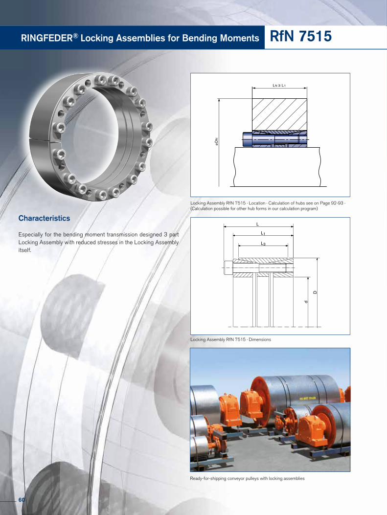
RINGFEDER® Locking Assemblies for Bending Moments RfN 7515
Characteristics
Especially for the bending moment transmission designed 3 part Locking Assembly with reduced stresses in the Locking Assembly itself.
Ready-for-shipping conveyor pulleys with locking assemblies
d
D
L
L1
L3
Locking Assembly RfN 7515 · Dimensions
LN ≥ L1
ø D
N
Locking Assembly RfN 7515 · Location · Calculation of hubs see on Page 92-93 · (Calculation possible for other hub forms in our calculation program)
60

RINGFEDER® Locking Assemblies for Bending Moments
Remark! The values of the shaft- and hub pressures have been calculated with the screw tightening shown in the tables. Reduction of the screw tightening torque results in different calculation values! The specified pressures at Mbmax. are sometimes very low. An operation near these limit values may therefore lead to in-creased fretting corrosion! More options with reduced bending moments (Mb 20% - Mb 80%) can be found on our website.
RfN 7515
More sizes on requestExplanations to tables: Page 49Series d D
RfN 7515 11.811 14.764
Ordering example: RfN 7515
Locking Assembly dimensions Locking screws
ISO 4762-12.9 Tres. pWmax pNmax pWmin pNmin Fax
at at
Mbmax.
at
Mbmax.
at
Mbmax. Gwd x D d x D L L1 L3 nSc DG TA T pW pN Mbmax.Mbmax.
mm inch inch pcs. ft-lbs ft-lbs psi ft-lbs psi psi psi lbs lbs
60 x 95 2.362 x 3.740 2.283 1.969 1.654 8 M8 x 1.575 30 3171 26957 17101 2065 2406 33043 20870 21014 13188 24523 3.3
70 x 110 2.756 x 4.331 2.756 2.362 1.969 8 M10 x 1.969 61 5370 28551 18116 3717 3874 35072 22319 22029 14058 33747 6.0
80 x 120 3.150 x 4.724 2.756 2.362 1.969 10 M10 x 1.969 61 7670 31304 20870 5318 5527 39420 26232 23043 15362 42071 6.0
90 x 130 3.543 x 5.118 2.756 2.362 1.969 11 M10 x 1.969 61 9492 30580 21159 6557 6863 39420 27391 21594 14928 46571 6.4
100 x 145 3.937 x 5.709 3.228 2.756 2.362 10 M12 x 2.362 107 13926 30290 20870 7435 11775 36812 25362 23623 16232 71769 9.5
110 x 155 4.331 x 6.102 3.228 2.756 2.362 10 M12 x 2.362 107 15319 27536 19565 8165 12961 34058 24203 20870 14783 71994 9.9
120 x 165 4.724 x 6.496 3.228 2.756 2.362 11 M12 x 2.362 107 18383 27681 20145 10687 14956 35652 25942 19855 14348 76044 11.0
130 x 180 5.118 x 7.087 3.583 3.110 2.559 14 M12 x 2.756 107 25346 30000 21739 14538 20763 37971 27536 22029 15942 97417 14.6
140 x 190 5.512 x 7.480 3.583 3.110 2.559 15 M12 x 2.756 107 29245 29855 22029 14338 25489 37246 27391 22609 16667 111141 15.4
150 x 200 5.906 x 7.874 3.583 3.110 2.559 15 M12 x 2.756 107 31334 27971 20870 20114 24026 37536 28116 18406 13768 97642 16.5
160 x 210 6.299 x 8.268 3.583 3.110 2.559 16 M12 x 2.756 107 35651 27971 21304 16263 31725 35270 26852 20756 15821 120947 17.4
170 x 225 6.693 x 8.858 4.173 3.622 3.071 15 M14 x 3.150 170 48525 28261 21304 22791 42840 35270 26562 21336 16111 153544 24.0
180 x 235 7.087 x 9.252 4.173 3.622 3.071 15 M14 x 3.150 170 51379 26667 20435 33058 39332 36232 27681 17101 13043 133312 25.1
190 x 250 7.480 x 9.843 4.567 4.016 3.465 16 M14 x 3.150 170 57849 23913 18116 40168 61660 32803 24965 15095 11466 138033 32.2
200 x 260 7.874 x 10.236 4.567 4.016 3.465 18 M14 x 3.150 170 68506 25507 19565 29849 62003 31787 24530 19304 14805 180522 32.6
220 x 285 8.661 x 11.220 4.961 4.331 3.780 15 M16 x 3.543 262 85897 25072 19275 55960 65167 34203 26377 15797 12174 180660 43.9
240 x 305 9.449 x 12.008 4.882 4.252 3.780 20 M16 x 3.543 262 124940 30580 24058 32054 120757 35561 28013 25546 20175 306639 47.4
260 x 325 10.236 x 12.795 5 4.370 3.780 20 M16 x 3.543 262 142120 26667 21449 49719 125888 32077 25691 18869 15095 295174 50.5
280 x 355 11.024 x 13.976 5.157 4.370 3.780 15 M20 x 3.543 509 169788 29710 23478 82711 148280 40205 31739 19304 15240 322826 73.0
300 x 375 11.811 x 14.764 5.157 4.370 3.780 16 M20 x 3.543 509 194044 29565 23623 92403 170631 40495 32367 18724 14950 346655 67.5
320 x 405 12.598 x 15.945 6.142 5.354 4.882 20 M20 x 4.331 509 258725 27391 21739 125422 226288 36577 28884 18288 14515 431183 102.1
340 x 425 13.386 x 16.732 6.142 5.354 4.882 20 M20 x 4.331 509 274896 25797 20725 152545 228687 36232 28986 15362 12319 410365 107.8
360 x 455 14.173 x 17.913 6.890 6.102 5.512 20 M22 x 5.118 686 359608 25217 19855 196024 301484 34638 27391 15652 12319 510932 145.9
380 x 475 14.961 x 18.701 6.890 6.102 5.512 20 M22 x 5.118 686 379587 23768 19130 258755 277726 35797 28551 11884 9565 445912 153.2
400 x 495 15.748 x 19.488 6.890 6.102 5.512 22 M22 x 5.118 686 439521 24928 20145 272363 344960 36812 29710 12899 10435 526006 161.8
420 x 515 16.535 x 20.276 6.890 6.102 5.512 24 M22 x 5.118 686 503452 25942 21159 211235 456987 34690 28303 17127 13934 663186 168.7
440 x 535 17.323 x 21.063 6.890 6.102 5.512 24 M22 x 5.118 686 527426 24638 20290 286034 443120 36141 29710 13333 10886 613953 176.4
460 x 555 18.110 x 21.850 6.890 6.102 5.512 24 M22 x 5.118 686 551400 23623 19565 342184 432370 36722 30480 10596 8854 573038 183.0
480 x 575 18.898 x 22.638 6.890 6.102 5.512 25 M22 x 5.118 686 599347 23623 19710 322446 505209 35415 29610 11757 9870 641605 189.6
500 x 595 19.685 x 23.425 6.890 6.102 5.512 25 M22 x 5.118 686 624320 22609 18986 322179 534758 33964 28594 11321 9580 651946 198.4
520 x 615 20.472 x 24.213 6.890 6.102 5.512 28 M22 x 5.118 686 727208 24348 20580 373472 623968 37012 31351 11757 10015 731528 205.0
540 x 635 21.260 x 25.000 6.890 6.102 5.512 28 M22 x 5.118 686 755178 23478 20000 464375 595524 38551 32754 8406 7101 672693 211.6
560 x 655 22.047 x 25.787 6.890 6.102 5.512 30 M22 x 5.118 686 839086 24203 20725 399464 737886 36867 31496 11757 10015 803242 222.7
580 x 675 22.835 x 26.575 6.890 6.102 5.512 30 M22 x 5.118 686 869054 23478 20145 490405 717452 38318 32948 8564 7402 754009 229.3
600 x 695 23.622 x 27.362 6.890 6.102 5.512 30 M22 x 5.118 686 899021 22609 19565 577020 689395 39479 34109 5806 4935 700505 238.1
620 x 715 24.409 x 28.150 6.890 6.102 5.512 30 M22 x 5.118 686 928988 21884 18986 670564 642915 40870 35415 2899 2613 632163 246.9
640 x 735 25.197 x 28.937 6.890 6.102 5.512 30 M22 x 5.118 686 958956 21159 18551 466034 838083 33964 29610 8418 7402 798296 255.7
Surface finishes For shaft bores Ra ≤ 1,6 µm For hub bores Ra ≤ 3,2 µm
Tolerances We recommend the following mounting tolerances Shaft h8 · Hub H8
61

RINGFEDER® Locking Elements
62

RfN 8006solid
RfN 8006slit
63

CharacteristicsCustomized application – by varying the number of Locking Elements, size and quantity of clamping screws, the connection can be adapted to fit most applications concerning surface pressures, materials, hub/shaft dimensions and available mounting space.
Transmission of high loads – to increase the transmissible torque and axial forces up to 4 Locking Elements can be used in series (see page 68).
Maximum reliability – no matter whether the connection is subjected to static, pulsating, dynamic or intermittent loads.
Simple manufacture – shaft and hub are designed without keyway. Apart from this,relatively large tolerances are admissible.
Easy adjustability – Locking Elements work without positive connection. So they can be adjusted at any place to any position by following the simple installation and removal instructions.
Backlash-free – the locking element connection is a mechanical shrink fit and will not wear or loosen in service provided that the maximum transmissible values for the connec-tion are not exceeded.
High fatigue strength under alternating torsional stresses – as neither the shaft nor the hub have grooves the notch effect is minimized and a higher polar section modulus is given, enabling the use of smaller diameters.
Simple installation – in comparison to cross-press fits temperature treatments and fitting are eliminated. Screws have to be tightened with standard tools.
Easy removal – Locking Elements are self releasing no additional measures or auxiliary equipment is required.
Wear and maintenance-free – unlimited lifetime if designed and used correctly.
RINGFEDER® Locking Elements
64

Explanations to tables
Basic dimensions when screws are not tightened
d = Inner diameter
D = Outer diameter
L = Overall length
L3 = Width of inner ring
At = Bearing surface = π · d · L3
T100 = Transmissible torque based on p=14500 psi
Fax100 = Transmissible axial force based on 14500 psi
X (n) = Min. distance to thrust flange for (n) Locking Element(s). Any reduction of this value could cause that the required transmission value is not achieved.
F0 = Clamping force for gap filling to establish
manufacturing tolerances - not for slit version
FA = Needed clamping force to get a shaft pressure of 14500 psi
dS1 = Diameter spacer sleeve inside
DS1 = Diameter spacer sleeve outside
Tmax = Max. transmissible torque
Gw = Weight
65

RINGFEDER® Locking Elements RfN 8006
solid
slit
L
L3D
d
X
d S1
DS
1
d
D
RINGFEDER® Locking Element RfN 8006 · Location
RINGFEDER® Locking Elements RfN 8006 · Dimensions
V-belt pulley
66

* Generally slit. At Locking Elements in slit version FO is eliminated in the calculation. To continue see next page
RfN 8006
Explanations to tables: Page 65
Locking Element dimensions Clamping force Transmissible torques Locking element Diameter spacer
or axial forces sleeve
1 2 3 4 inside outside
d x D d D L L3 At F0 FA T100 Fax100 x Gw dS1 DS1 Tmax
inch mm mm inch inch2 lbs ft-lbs lbs inch lbs inch ft-lbs* 0.236 x 0.354 *6 9 0.177 0.146 0.107 - 832 1.8 187 0.079 0.079 0.118 0.118 0.0033 0.240 0.350 5.8* 0.276 x 0.394 *7 10 0.177 0.146 0.124 - 989 2.5 218 0.079 0.079 0.118 0.118 0.0031 0.280 0.390 7.6* 0.315 x 0.433 *8 11 0.177 0.146 0.140 - 1124 3.2 247 0.079 0.079 0.118 0.118 0.0033 0.319 0.429 9.70.354 x 0.472 9 12 0.177 0.146 0.163 1709 1281 4.2 286 0.079 0.079 0.118 0.118 0.004 0.358 0.469 6.40.394 x 0.512 10 13 0.177 0.146 0.180 1563 1416 5.2 315 0.079 0.079 0.118 0.118 0.004 0.398 0.508 8.90.433 x 0.551 11 14 0.177 0.146 0.198 1686 1551 5.9 337 0.079 0.079 0.118 0.118 0.004 0.437 0.547 10.80.472 x 0.591 12 15 0.177 0.146 0.215 1551 1686 7.4 375 0.079 0.079 0.118 0.118 0.005 0.476 0.587 13.80.512 x 0.630 13 16 0.177 0.146 0.234 1439 1844 8.9 407 0.118 0.079 0.118 0.118 0.005 0.516 0.626 17.20.551 x 0.709 14 18 0.248 0.209 0.361 2518 2833 14.8 629 0.118 0.118 0.157 0.197 0.011 0.555 0.705 25.00.591 x 0.748 15 19 0.248 0.209 0.388 2406 3035 17.0 674 0.118 0.118 0.157 0.197 0.012 0.594 0.744 30.00.630 x 0.787 16 20 0.248 0.209 0.412 2271 3237 19.2 717 0.118 0.118 0.157 0.197 0.012 0.634 0.783 36.00.669 x 0.827 17 21 0.248 0.209 0.439 2136 3440 21.4 764 0.118 0.118 0.157 0.197 0.013 0.673 0.823 42.00.709 x 0.866 18 22 0.248 0.209 0.465 2046 3642 24.0 809 0.118 0.118 0.157 0.197 0.014 0.713 0.862 48.00.748 x 0.945 19 24 0.248 0.209 0.490 2833 3844 27.0 852 0.118 0.118 0.157 0.197 0.017 0.756 0.937 67.00.787 x 0.984 20 25 0.248 0.209 0.516 2698 4047 30.0 899 0.118 0.118 0.157 0.197 0.018 0.795 0.976 76.00.866 x 1.024 22 26 0.248 0.209 0.567 2023 4451 35.0 989 0.118 0.118 0.157 0.197 0.016 0.874 1.016 73.00.945 x 1.102 24 28 0.248 0.209 0.620 1866 4856 43.0 1079 0.118 0.118 0.157 0.197 0.017 0.953 1.094 90.00.984 x 1.181 25 30 0.248 0.209 0.645 2226 5058 46.0 1124 0.118 0.118 0.157 0.197 0.022 0.992 1.173 126.01.102 x 1.260 28 32 0.248 0.209 0.722 1664 5665 58.0 1259 0.118 0.118 0.157 0.197 0.020 1.110 1.252 126.01.181 x 1.378 30 35 0.248 0.209 0.773 1911 6070 66.0 1349 0.118 0.118 0.157 0.197 0.027 1.189 1.370 186.01.260 x 1.417 32 36 0.248 0.209 0.826 1754 6475 75.0 1439 0.118 0.118 0.157 0.197 0.022 1.268 1.409 164.01.378 x 1.575 35 40 0.276 0.236 1.021 2271 8004 102.0 1776 0.118 0.118 0.157 0.197 0.044 1.386 1.567 250.01.417 x 1.654 36 42 0.276 0.236 1.051 2608 8228 108.0 1844 0.118 0.118 0.157 0.197 0.044 1.425 1.646 324.01.496 x 1.732 38 44 0.276 0.236 1.110 2473 8701 120.0 1933 0.118 0.118 0.157 0.197 0.044 1.504 1.724 363.01.575 x 1.772 40 45 0.315 0.260 1.285 3103 10117 147.0 2237 0.118 0.157 0.197 0.236 0.044 1.583 1.764 316.01.654 x 1.890 42 48 0.315 0.260 1.349 3507 10567 162.0 2338 0.118 0.157 0.197 0.236 0.066 1.661 1.882 428.01.772 x 2.047 45 52 0.394 0.339 1.883 5868 14838 242.0 3282 0.118 0.157 0.197 0.236 0.110 1.780 2.039 553.01.890 x 2.165 48 55 0.394 0.339 2.009 5531 15737 275.0 3507 0.118 0.157 0.197 0.236 0.110 1.898 2.157 638.01.969 x 2.244 50 57 0.394 0.339 2.093 5283 16412 299.0 3642 0.118 0.157 0.197 0.236 0.110 1.976 2.236 699.02.165 x 2.441 55 62 0.394 0.339 2.302 4901 17986 361.0 4002 0.118 0.157 0.197 0.236 0.110 2.173 2.433 859.02.205 x 2.520 56 64 0.472 0.409 2.835 6610 22257 454.0 4946 0.118 0.157 0.197 0.276 0.154 2.213 2.512 1007.02.362 x 2.677 60 68 0.472 0.409 3.036 6160 23831 520.0 5283 0.118 0.157 0.197 0.276 0.154 2.370 2.669 1170.02.480 x 2.795 63 71 0.472 0.409 3.188 5913 24955 575.0 5576 0.118 0.157 0.197 0.276 0.176 2.488 2.787 1299.02.559 x 2.874 65 73 0.472 0.409 3.291 5710 25854 612.0 5755 0.118 0.157 0.197 0.276 0.176 2.567 2.866 1389.02.756 x 3.110 70 79 0.551 0.480 4.157 6969 32599 826.0 7194 0.118 0.197 0.236 0.276 0.243 2.768 3.098 1816.02.795 x 3.150 71 80 0.551 0.480 4.216 6969 33049 856.0 7329 0.118 0.197 0.236 0.276 0.243 2.807 3.138 1869.02.953 x 3.307 75 84 0.551 0.480 4.453 7779 34847 952.0 7734 0.157 0.197 0.236 0.276 0.265 2.965 3.295 2067.03.150 x 3.583 80 91 0.669 0.591 5.840 10791 45638 1335.0 10117 0.157 0.197 0.236 0.315 0.265 3.161 3.571 2882.03.346 x 3.780 85 96 0.669 0.591 6.206 10252 48561 1505.0 10791 0.157 0.197 0.236 0.315 0.441 3.358 3.768 3277.03.543 x 3.976 90 101 0.669 0.591 6.570 9757 51484 1689.0 11466 0.157 0.197 0.236 0.315 0.441 3.555 3.965 3696.03.740 x 4.173 95 106 0.669 0.591 6.936 9263 54406 1881.0 12140 0.157 0.197 0.236 0.315 0.485 3.752 4.161 4141.03.937 x 4.488 100 114 0.827 0.736 9.102 13647 71268 2596.0 15737 0.157 0.236 0.276 0.354 0.882 3.949 4.476 5866.04.331 x 4.882 110 124 0.827 0.736 10.011 14838 78462 3135.0 17311 0.157 0.236 0.276 0.354 0.882 4.343 4.870 7060.04.724 x 5.276 120 134 0.827 0.736 10.921 13534 85432 3725.0 18885 0.197 0.236 0.276 0.354 1.103 4.736 5.264 8472.05.118 x 5.827 130 148 1.102 0.996 16.008 21628 125450 5938.0 27878 0.197 0.276 0.354 0.433 1.874 5.134 5.811 12794.05.512 x 6.220 140 158 1.102 0.996 17.239 20009 134892 6897.0 30126 0.197 0.276 0.354 0.433 2.007 5.528 6.205 14930.05.906 x 6.614 150 168 1.102 0.996 18.470 18997 144559 7893.0 32149 0.197 0.276 0.354 0.433 2.139 5.921 6.598 17199.06.299 x 7.008 160 178 1.102 0.996 19.702 17648 154227 8999.0 34285 0.236 0.276 0.354 0.433 2.249 6.315 6.992 19648.06.693 x 7.520 170 191 1.299 1.181 24.822 26416 194469 12023.0 43165 0.236 0.315 0.394 0.472 3.308 6.713 7.500 25739.07.087 x 7.913 180 201 1.299 1.181 26.282 25000 205935 13499.0 45863 0.236 0.315 0.394 0.472 3.528 7.106 7.894 28951.07.480 x 8.307 190 211 1.299 1.181 27.742 23606 217176 15048.0 48112 0.236 0.315 0.394 0.472 3.749 7.500 8.287 32352.07.874 x 8.819 200 224 1.496 1.370 33.874 30126 265288 19326.0 58903 0.236 0.315 0.433 0.512 5.072 7.898 8.795 41035.08.268 x 9.213 210 234 1.496 1.370 35.568 28552 278552 21318.0 61826 0.236 0.315 0.433 0.512 5.513 8.291 9.189 45348.08.661 x 9.606 220 244 1.496 1.370 37.262 27428 291817 23383.0 64748 0.236 0.315 0.433 0.512 5.513 8.685 9.583 49751.09.055 x 10.118 230 257 1.693 1.555 44.217 37095 346223 29063.0 76888 0.236 0.354 0.472 0.551 7.497 9.079 10.094 61131.09.449 x 10.512 240 267 1.693 1.555 46.139 35409 361960 31718.0 80486 0.276 0.354 0.472 0.551 7.718 9.472 10.488 66689.09.843 x 11.024 250 280 1.890 1.732 53.785 42716 420414 38357.0 93300 --- 0.394 0.512 0.630 10.364 9.874 10.992 80543.010.236 x 11.417 260 290 1.890 1.732 55.955 40917 438399 41676.0 97797 0.276 0.394 0.512 0.630 10.584 10.268 11.386 87249.010.630 x 11.811 270 300 1.890 1.732 58.125 39793 456385 44996.0 101169 0.276 0.394 0.512 0.630 10.805 10.661 11.780 94157.011.024 x 12.323 280 313 2.087 1.929 66.805 46313 523831 53479.0 116906 0.276 0.433 0.551 0.669 13.892 11.055 12.291 111663.011.417 x 12.717 290 323 2.087 1.929 69.130 49910 541817 57167.0 120279 0.276 0.433 0.551 0.669 14.333 11.449 12.685 119337.0
* Generally slit. At Locking Elements in slit version FO is eliminated in the calculation.
67

Locking screw calculationLocking screw tableThe torque transmission capacity of a RINGFEDER® Locking Element connection is directly proportional to the effective clam-ping force FA. As clamping elements normally locking srews are used which act on the Locking Elements via a thrust flange. According to the required tension force, the selection according to screw quality, size and quantity can be done according to the chart below.
RINGFEDER® Locking Elements RfN 8006
Regular thread 1), metric
8.8 10.9 12.9 dG TA FV TA FV TA FV
M 4 2.9 3 900 4.1 5 450 4.9 6 550 M 5 6.0 6 350 8.5 8 950 10 10 700 M 6 10 9 000 14 12 600 17 15 100
M 8 25 16 500 35 23 200 41 27 900
M 10 49 26 200 69 36 900 83 44 300 M 12 86 38 300 120 54 000 145 64 500 M 14 135 52 500 190 74 000 230 88 500
M 16 210 73 000 295 102 000 355 123 000 M 18 290 88 000 405 124 000 485 148 000 M 20 410 114 000 580 160 000 690 192 000
M 22 550 141 000 780 199 000 930 239 000 M 24 710 164 000 1000 230 000 1200 276 000 M 27 1050 215 000 1500 302 000 1800 363 000
M 30 1450 262 000 2000 368 000 2400 442 000
1 Nm = 0.738 lb-ft1 N = 0.225 lb
Regular thread, inch
BOLT SIZE
BOLT DIA.
FV TABOLT SIZE
BOLT DIA.
FV TA
Inch Inch lbs lb-in Inch Inch lbs lb-ft
4-40 0.112 540 12 1/4"-20 0.25 2850 12
4-48 0.112 600 13 1/4"-28 0.25 3250 14
6-32 0.138 820 23 5/16"-18 0.3125 4700 25
6-40 0.138 920 25 5/16"-24 0.3125 5200 25
8-32 0.164 1260 41 3/8"-16 0.375 6950 45
8-36 0.164 1320 43 3/8"-24 0.375 7900 50
10-24 0.19 1580 60 7/16"-14 0.4375 9600 70
10-32 0.19 1800 68 7/16"-20 0.4375 10700 80
1/2"-13 0.5 12800 110
1/2"-20 0.5 14400 120
9/16"-12 0.5625 16400 150
9/16"-18 0.5625 18300 170
ConcentricityThe relatively narrow RINGFEDER® RfN 8006 Locking Elements mainly serve the purpose of transmitting large torques and axial forces. They are not self-centering. The concentricity accuracy of the clamped hub therefore depends on the centering and care of the installation. Lo-cking Elements RfN 8006 can centre themselves within the framework of their production accuracy if they are ab-solutely plane-parallel when pressed together.
68

Mounting of Locking ElementThe values for T and Fax, apply to Locking Elements installed in oiled condition.
Surface finishesFor shafts and hub bores Ra ≤ 1 µm
Required screw tension force for Locking Elements solid: FA = FA´ + F0for Locking Elements slit: FA = FA´
Where n-Locking Elements are used one behind the other (series), the following applies to the increase in T und Fax :
Tn = T1 · m and Faxn = Fax1 · m
Retaining the values for T and Fax it is possible to reduce FA´ and p when using elements in series:
FA´n = FA´/m and PN = p/m
With 2 / 3 / 4 Locking Elements, m = 1.555 / 1.86 / 2.03
1) Approx. values
The fits specified have given excellent service in practical operations. Naturally, the shafts and the bores can feature other clearances. (Please contact our technical department for assistance).
RfN 8006
d Element1) Shaft Bore
up to 38 E7/f7 h6 H7
above 38 E8/e8 h8 H8
Explanations to tables: Page 65 More sizes on request
Ordering example: RfN 8006 slit
Series d D Further details
RfN 8006 11.811 13.110 G (= slit)
Ordering example: RfN 8006 unslit
Series d D
RfN 8006 11.811 13.110
Locking Element dimensions Clamping force Transmissible torques Locking element Diameter spacer
or axial forces sleeve
1 2 3 4 inside outside
d x D d D L L3 At F0 FA T100 Fax100 x Gw dS1 DS1 Tmax
inch mm mm inch inch2 lbs ft-lbs lbs inch lbs inch ft-lbs11.811 x 13.110 300 333 2.087 1.929 71.610 48112 559802 61224.0 124775 0.276 0.433 0.551 0.669 14.774 11.843 13.079 127854.012.598 x 14.173 320 360 2.559 2.323 91.915 65647 719424 84090.0 159622 0.394 0.591 0.787 0.984 24.035 12.638 14.134 177231.013.386 x 14.961 340 380 2.559 2.323 97.650 61151 764388 94786.0 169739 0.394 0.591 0.787 0.984 25.358 13.425 14.921 200420.014.173 x 15.748 360 400 2.559 2.323 103.385 58004 809353 106219.0 179856 0.394 0.591 0.787 0.984 26.901 14.213 15.709 224858.014.961 x 16.535 380 420 2.559 2.323 109.120 60477 854317 118390.0 189973 0.394 0.591 0.787 0.984 28.224 15.000 16.496 249923.015.748 x 17.323 400 440 2.559 2.323 115.010 57554 899281 131299.0 200090 0.394 0.591 0.787 0.984 29.768 15.787 17.283 277097.016.535 x 18.110 420 460 2.559 2.323 120.590 54856 944245 144576.0 210207 0.394 0.591 0.787 0.984 31.091 16.575 18.071 305640.017.323 x 18.898 440 480 2.559 2.323 126.325 52608 989209 158592.0 220324 0.394 0.591 0.787 0.984 32.414 17.362 18.858 335509.018.110 x 19.685 460 500 2.559 2.323 132.215 50341 1123685 188817.9 249677 0.394 0.591 0.787 0.984 36.597 19.724 21.220 366572.318.898 x 20.472 480 520 2.559 2.323 137.950 53712 1123685 253724.1 321367 0.394 0.591 0.787 0.984 36.597 19.724 21.220 366572.319.685 x 21.260 500 540 2.559 2.323 143.530 51465 1123685 205044.5 249677 0.394 0.591 0.787 0.984 36.597 19.724 21.220 432216.020.472 x 22.441 520 570 3.150 2.874 184.450 75961 1449554 275113.6 322041 0.472 0.709 0.945 1.181 59.304 20.512 22.402 432216.021.260 x 23.228 540 590 3.150 2.874 192.200 73264 1505738 296503.1 1578967 0.472 0.709 0.945 1.181 61.509 21.299 23.189 633572.622.047 x 24.016 560 610 3.150 2.874 198.400 70567 1561922 318630.2 346986 0.472 0.709 0.945 1.181 63.493 22.087 23.976 681514.722.835 x 24.803 580 630 3.150 2.874 206.150 68320 1618106 342232.5 359346 0.472 0.709 0.945 1.181 65.698 22.874 24.764 730931.923.622 x 25.591 600 650 3.150 2.874 213.900 74388 1674291 366572.3 372156 0.472 0.709 0.945 1.181 67.902 23.661 25.551 780349.124.409 x 26.378 620 670 3.150 2.874 220.100 72141 1730475 391229.3 384516 0.472 0.709 0.945 1.181 70.107 24.449 26.339 832716.525.197 x 27.165 640 690 3.150 2.874 227.850 69893 1786659 416727.1 397101 0.472 0.709 0.945 1.181 72.312 25.236 27.126 887296.725.984 x 27.953 660 710 3.150 2.874 234.050 67871 1842843 443279.6 409462 0.472 0.709 0.945 1.181 74.516 26.024 27.913 943352.026.772 x 28.740 680 730 3.150 2.874 241.800 66073 1899028 470569.7 422047 0.472 0.709 0.945 1.181 76.500 26.811 28.701 1001620.127.559 x 29.528 700 750 3.150 2.874 248.000 64275 1955212 499076.0 434470 0.472 0.709 0.945 1.181 78.926 27.598 29.488 1061519.628.346 x 30.315 720 770 3.150 2.874 255.750 62477 2011396 528086.1 446955 0.472 0.709 0.945 1.181 80.910 28.386 30.276 1122906.829.134 x 31.102 740 790 3.150 2.874 263.500 60904 2067580 557915.6 459440 0.472 0.709 0.945 1.181 83.114 29.173 31.063 1185957.229.921 x 31.890 760 810 3.150 2.874 269.700 66522 2123765 588565.4 471925 0.472 0.709 0.945 1.181 85.319 29.961 31.850 1248738.530.709 x 32.677 780 830 3.150 2.874 277.450 64949 2179949 620033.8 484409 0.472 0.709 0.945 1.181 87.965 30.748 32.638 1315181.731.496 x 33.465 800 850 3.150 2.874 283.650 63151 2224896 649044.6 494397 0.472 0.709 0.945 1.181 89.728 31.535 33.425 1383412.832.283 x 34.252 820 870 3.150 2.874 291.400 61803 2281081 682070.1 506882 0.472 0.709 0.945 1.181 91.933 32.323 34.213 1453234.233.071 x 35.039 840 890 3.150 2.874 299.150 60230 2337265 715915.7 519367 0.472 0.709 0.945 1.181 93.917 33.110 35.000 1524844.133.858 x 35.827 860 910 3.150 2.874 305.350 59106 2393449 750580.7 531852 0.472 0.709 0.945 1.181 96.122 33.898 35.787 1598035.434.646 x 36.614 880 930 3.150 2.874 313.100 57533 2449633 786064.5 544336 0.472 0.709 0.945 1.181 98.547 34.685 36.575 1673086.135.433 x 37.402 900 950 3.150 2.874 319.300 56184 2505818 822368.4 556821 0.472 0.709 0.945 1.181 100.531 35.472 37.362 1749784.536.220 x 38.189 920 970 3.150 2.874 327.050 55285 2562002 859491.8 569306 0.472 0.709 0.945 1.181 102.735 36.260 38.150 1828052.537.008 x 38.976 940 990 3.150 2.874 334.800 53937 2618186 897434.6 581791 0.472 0.709 0.945 1.181 104.940 37.047 38.937 1908185.837.795 x 39.764 960 1010 3.150 2.874 341.000 60679 2674370 936197.6 594275 0.472 0.709 0.945 1.181 107.145 37.835 39.724 1987206.138.583 x 40.551 980 1030 3.150 2.874 348.750 59331 2730555 975779.3 606760 0.472 0.709 0.945 1.181 109.129 38.622 40.512 2070718.239.370 x 41.339 1000 1050 3.150 2.874 354.950 58207 2786739 1016180.4 619245 0.472 0.709 0.945 1.181 111.554 39.409 41.299 2155867.7
69

Hub bolted clamp plate (hub axially adjustable)
Shaft bolted clamp plate (hub axially fixed)
Explanations
d = Inner diameterd = Inner diameter (metric)D = Outer diameterCd = Machining tolerances for shaftCD = Machining tolerances for counter boreL = Overall lengthL3 = Width of inner ringF0 = Clamping force for gap filling to establish manufacturing tolerances - not for slit versionFA10 = Needed clamping force to get a shaft pressure of 10,000 psiT10 = Transmissible torque based on 10,000 psiFax10 = Transmissible axial force based on p=10,000 psiGw = Weight
70
RINGFEDER® Locking ElementsAluminum Alloy*RfN 8006 GSA
GSA

* Stainless steel available upon request. * Delivery on request; other sizes stocked. Contact RINGFEDER CORPORATION for additional sizes and information.
Series Size d
GSA GSA -812 0.8125
Ordering example: GSA
Selection Guide
1. Determine the shaft diameter to be used and the maximum torque (T) to be transmitted.
T= 63,000 (lb-in) x HP RPM
2. Select a locking element from the specification table for the shaft diameter. Verify that the transmissible torque (T) for the element meets the torque requirement.
Note: Required peak torque should never exceed specified transmissible torque (T ). Higher torque capacitites can be obtained by increasing the locking force.
3. Determine the required locking force (FA’). A pre-load (FO) is required to bridge the clearance for the specified fits. The total required locking force is FA=FO + FA’. The locking force is normally obtained by using one or more screws and a clamp plate.
4. Refer to screw tables on page 64 to determine the number, size and grade of screws needed for the required locking force and individual screw clamp load.
Clamp load/screw = required locking force (FA) or FA’ number of screws (z)
Locking Element dimensions Clamping force
d d x D Cd CD L L3 F0 FA10 T10 Fax10 Gw
mm inch inch inch inch lbs ft-lbs lbs lbs6.35 0.2500 x 0.3750 0 / -0.0005 0.0005 /0 0.126 0.094 580 450 1.2 112 0.76 / 10007,94 0.3125 x 0.4375 0 / -0.0005 +0.0005 /0 0.143 0.112 686 670 2.2 166 1.04 / 10009.53 0.3750 x 0.5000 0 / -0.0005 +0.0005 /0 0.160 0.128 673 920 3.6 229 1.35 / 100011.11 0.4375 x 0.5937 0 / -0.0005 +0.0005 /0 0.176 0.143 796 1196 5.4 297 2.20 / 100012.70 0.5000 x 0.6562 0 / -0.001 +0.001 /0 0.193 0.158 944 1512 7.8 376 2.69 / 100014.29 0.5625 x 0.7500 0 / -0.001 +0.001 /0 0.210 0.174 1259 1872 11 469 3.97 / 100015,88 0.6250 x 0.8125 0 / -0.001 +0.001 /0 0.226 0.178 1231 2237 15 560 4.69 / 100017.46 0.6875 x 0.8750 0 / -0.001 +0.0015 /0 0.243 0.203 1414 2670 19 669 5.47 / 100019.05 0.7500 x 0.9375 0 / -0.001 +0.0015 /0 0.260 0.219 1413 3145 25 295 6.33 / 100020.64 0.8125 x 1.0312 0 / -0.001 +0.0015 /0 0.276 0.234 1617 3637 31 911 8.56 / 100022.23 0.8750 x 1.0937 0 / -0.001 +0.0015 /0 0.293 0.250 1611 4188 38 1047 10.14 / 100023.81 0.9375 x 1.1875 0 / -0.001 +0.0015 /0 0.310 0.267 2087 4790 47 1197 12.36 / 100025.4 1.0000 x 1.2500 0 / -0.001 +0.0015 /0 0.326 0.284 2090 5437 57 1360 14.05 / 100028.58 1.1250 x 1.4060 0 / -0.0015 +0.0015 /0 0.359 0.312 2220 6620 70 1493 19.55 / 100031.75 1.2500 x 1.5310 0 / -0.0015 +0.0015 /0 0.393 0.344 2240 8150 95 1824 23.54 / 100034.93 1.3750 x 1.6870 0 / -0.002 + 0.002 /0 0.426 0.376 2745 9750 126 2196 31.22 / 100038.1 1.5000 x 1.8120 0 / -0.002 +0.002 /0 0.459 0.407 3030 11510 162 2587 36.38 / 100041.28 1.6250 x 1.9680 0 / -0.002 +0.002 /0 0.492 0.437 3295 13390 204 3015 46.43 / 100044.45 1.7500 x 2.1250 0 / -0.002 +0.002 /0 0.526 0.469 3585 15475 254 3480 58.53 / 100047.63 1.8750 x 2.2500 0 / -0.002 +0.002 /0 0.559 0.500 3595 17675 311 3979 66.22 / 100050.8 2.0000 x 2.4060 0 / -0.003 +0.003 /0 0.592 0.528 5365 19910 373 4480 81.09 / 100057.15 2.2500 x 2.6560 0 / -0.003 +0.003 /0 0.592 0.528 4795 22400 472 5461 90.30 / 100061.91 2.4375 x 2.8430 0 / -0.003 +0.003 /0 0.592 0.528 4430 24260 544 5461 97.07 / 100063.50 2.5000 x 2.9060 0 / -0.003 +0.003 /0 0.592 0.528 4330 24885 583 5600 99.50 / 100068.26 2.6875 x 3.0930 0 / -0.003 +0.003 /0 0.592 0.528 4035 26750 674 6020 106.26 /100069.85 2.7500 x 3.1560 0 / -0.003 +0.003 /0 0.592 0.528 3950 27370 706 6160 108.7 / 100076.2 3.0000 x 3.4060 0 / -0.003 +0.003/0 0.592 0.528 3890 29860 840 6720 117.9 / 1000
71
GSA

STAINLESS STEEL
RINGFEDER® Stainless steel products
72

Locking Assemblies Locking Elements
RfN 7110stainless steel
RfN 7012stainless steel
RfN 7061stainless steel
RfN 8006solid
stainless steel
RfN 8006slit
stainless steel
73
Characteristics
Inexpensive manufacture – the large tolerances that are possible and the simple turning process guarantee inexpensive manufacture.
Simple installation – only a few screws need to be tightened, alignment to precise angles between the hub and shaft is possible in any position, no fitting at assembly required.
Simple dismantling – RINGFEDER® Locking Assemblies are fitted with threaded ex-traction holes, so that no additional auxiliary equipment is necessary, series RfN 7012 is self-releasing.
Large constant reverse-torsion fatigue strength – shaft and hub are ungrooved, so that there is no weakening of these components. Shaft and hub can be designed to be considerably smaller (light, cost and space-saving design possible).
No danger of deflection – RINGFEDER® Locking Assemblies are absolutely backlash- free.
Effect similar to overload protection – after the set frictional connection force has been exceeded the Locking Assemblies simply slide. Valuable machine parts are protected. The Locking Assemblies are subject to the same laws as any other connection with force transmission by friction - not suitable as sliding clutch.
Completely maintenance-free – no follow-up costs.
RINGFEDER® Stainless steel products
74

STAINLESS STEEL
Explanations to tables
Basic dimensions when screws are not tightened
d = Inner diameter (decimal notation)
d = Inner diameter
D = Outer diameter
DB1 = Collar outer diameter L = Overall length L1 = Overall length without screws L3 = Width of inner ring L4 = Installation length up to collar T = Transmissible torque at given TA
Fax = Transmissible axial force
pW = Surface pressure on shaft at given TA pN = Surface pressure on hub at given TA nSc = Quantity of screws
DG = Thread
TA = Max. tightened torque of the clamping screws
DN min = Min. hub outer diameter depending of the given hub yield point (Rp0,2)
Tmax = Maximum transmissible torque
Gw = Weight
75

stainless steelRINGFEDER® Locking Assemblies RfN 7012-IN
Characteristics
Slimmest design, especially suitable for applications where space is limited. The Locking Assembly RfN 7012 stainless steel compen-sates small tolerance deviations and compensates small mounting errors.
Large transmittable forces and moments – several Locking Assemblies RfN 7012 stainless steel can be placed one behind the other. The transmissible torque and axial forces are added - please take in this respect consulting with our technical experts.
Easy installation – in comparison to cross-press fits temperature treatments and fitting are eliminated. Locking Assemblies RfN 7012 stainless steel can cover a big fitting clearance.
Low risk to contamination – during tightening process the func-tional surfaces of the device and connection are pressed together generating a surface pressure that does not allow the ingress of contamination.
Adjustable transmission values – the locking screw torque can be changed giving a corresponding change in transmission values. RfN 7012 stainless steel Locking Assemblies can be tightened and released repeatedly.
Example applications:
Chain wheels, levers, pulleys, slip-on gear mechanisms, belt drums, running wheels, cable sheaves
L
d
D
L3
L1
Locking Assembly RfN 7012 stainless steel · Dimensions
STAINLESS STEEL
76

Locking Assembly dimensions Transmissible torques Surface pressure Locking screws DN min.
or axial forces ISO 4762-A2-70 Rp0,2 [N/mm2]
Shaft Hub
d d x D L L1 L3 T Fax pW pN nSc DG TA Gw DHG 200 300 400
inch inch inch ft-lbs lbs psi pcs. ft-lbs lbs inch inch
0.750 3/4 x 1850 0.787 1083 0.669 185 5920 28450 11500 8 M 6 x 18 6 0.5 M 8 2404 2278 2149
1.000 1 x 1969 0.787 1083 0.669 275 6600 27000 13700 9 M 6 x 18 6 0.6 M 8 2697 2525 2355
1.125 1 1/8 x 2165 0.787 1083 0.669 345 7360 23720 12300 10 M 6 x 18 6 0.7 M 8 2868 2705 2542
1.1875 1 3/16 x 2159 0.813 1108 0.669 362 7316 24900 13700 10 M 6 x 18 6 0.7 M 8 2956 2768 2581
1.250 1 1/4 x 2362 0.787 1083 0.669 459 8813 28000 14800 12 M 6 x 18 6 0.7 M 8 3325 3093 2866
1.375 1 3/8 x 2365 0.776 1071 0.669 506 8832 25600 14900 12 M 6 x 18 6 0.7 M 8 3335 3101 2873
1.4375 1 7/16 x 2559 0.787 1083 0.669 608 10151 28450 16000 15 M 6 x 18 6 0.8 M 8 3710 3427 3155
1.500 1 1/2 x 2559 0.787 1083 0.669 636 10176 27000 15800 15 M 6 x 18 6 0.8 M 8 3695 3417 3148
1.625 1 5/8 x 2953 0.945 1319 0.787 1070 15803 32700 18000 12 M 8 x 22 10 1.3 M 10 4510 4114 3741
1.6875 1 11/16 x 2953 0.945 1319 0.787 1109 15772 28430 16200 12 M 8 x 22 10 1.3 M 10 4310 3975 3653
1.750 1 3/4 x 2953 0.945 1319 0.787 1150 15771 30000 17800 12 M 8 x 22 10 1.3 M 10 4484 4096 3730
1.875 1 7/8 x 3150 0.945 1319 0.787 1222 15642 28450 16900 12 M 8 x 22 10 1.4 M 10 4679 4298 3933
1.9375 1 15/16 x 3150 0.945 1319 0.787 1259 15595 27000 16600 12 M 8 x 22 10 1.4 M 10 4640 4270 3916
2.000 2 x 3346 0.945 1319 0.787 1519 18228 30600 18300 14 M 8 x 22 10 1.4 M 10 5151 4689 4256
2.125 2 1/8 x 3346 0.945 1319 0.787 1613 18217 29150 18500 14 M 8 x 22 10 1.4 M 10 5181 4710 4269
2.1875 2 3/16 x 3543 0.945 1319 0.787 1656 18169 28450 17600 14 M8 x 22 10 1.5 M 10 5350 4894 4462
2.250 2 1/4 x 3543 0.945 1319 0.787 1700 18133 27000 17100 14 M 8 x 22 10 1.5 M 10 5292 4854 4437
2.375 2 3/8 x 3531 0.996 1370 0.787 1787 18058 25600 17200 14 M 8 x 22 10 1.5 M 10 5284 4844 4426
2.4375 2 7/16 x 3740 0.945 1319 0.787 2098 20657 28450 18500 16 M 8 x 22 10 1.6 M 10 5796 5267 4773
2.500 2 1/2 x 3740 0.945 1319 0.787 2148 20621 27750 18500 16 M 8 x 22 10 1.6 M 10 5797 5268 4774
2.5625 2 9/16 x 3737 0.959 1333 0.787 2199 20596 27000 18500 16 M 8 x 22 10 1.6 M 10 5787 5260 4768
2.625 2 5/8 x 4331 1102 1555 0.945 3120 28526 30514 18500 14 M 10 x 25 19 2.8 M 12 6703 6094 5524
2.6875 2 11/16 x 4331 1102 1555 0.945 3195 28532 29804 18500 14 M 10 x 25 19 2.8 M 12 6703 6094 5524
2.750 2 3/4 x 4337 1079 1532 0.945 3320 28975 29850 18900 14 M 10 x 25 19 2.8 M 12 6791 6155 5565
2.875 2 7/8 x 4528 1102 1555 0.945 3450 28800 28450 18000 14 M 10 x 25 19 2.9 M 12 6928 6317 5742
2.9375 2 15/16 x 4528 1102 1555 0.945 3522 28775 27750 18000 14 M 10 x 25 19 2.9 M 12 6917 6309 5737
RfN 7012-IN
Arrangement of several Locking Assemblies RfN 7012 stainless steel
If several Locking Assemblies are to be installed the trans-mission values of the table can be added when the Lo-cking Assemblies are located within a distance of 4 · L .
Change of screw tightening torquesThe Locking Assemblies are generally equipped with A2-70 grade screws. A reduction of the screw tightening torque is possible. (Please contact our specialists for assistance).
Auxiliary ThreadsTo facilitate removal, the front thrust rings have auxiliary threads.
Calculation hub outer diameter Factor C=6 see page 92
Series d D Further details
RfN 7012-IN 2 3346 SST (= stainless steel)
Ordering example: RfN 7012-IN Surface finishes for shafts and hub bores Ra ≥ 3,2 µm
More sizes on requestExplanations to tables: Page 75
Mounting of Locking Assembly The Locking Assemblies are supplied slightly oiled and ready-to-use. The values for T, Fax, pW and pN apply to Locking Assemblies in delivery condition.
Surface finishes for shafts and hub bores Ra ≤ 3,2 µm
TolerancesWe recommend the following mounting tolerancesShaft: k9-h9; Hub: N9-H9Max. permissible: Shaft: k11-h11; Hub: N11-H11To avoid excessive deformations of the relatively thickwalled thrust rings, the Locking Assembly should be located as sym-metrically as possible between shaft and hub bore. If the shaft is smaller than nominal d, the bore should exceed nominal D to the same extent and vice versa. The concentricity quality is de-termined by the direct centering between shaft and hub.
77

RINGFEDER® Locking Assemblies RfN 7012stainless steel
Characteristics
Slimmest design, especially suitable for applications where space is limited. The Locking Assembly RfN 7012 stainless steel compen-sates small tolerance deviations and compensates small mounting errors.
Large transmittable forces and moments – several Locking Assemblies RfN 7012 stainless steel can be placed one behind the other. The transmissible torque and axial forces are added - please take in this respect consulting with our technical experts.
Easy installation – in comparison to cross-press fits temperature treatments and fitting are eliminated. Locking Assemblies RfN 7012 stainless steel can cover a big fitting clearance.
Low risk to contamination – during tightening process the func-tional surfaces of the device and connection are pressed together generating a surface pressure that does not allow the ingress of contamination.
Adjustable transmission values – the locking screw torque can be changed giving a corresponding change in transmission values. RfN 7012 stainless steel Locking Assemblies can be tightened and released repeatedly.
Example applications:
Chain wheels, levers, pulleys, slip-on gear mechanisms, belt drums, running wheels, cable sheaves
L
d
D
L3
L1
Locking Assembly RfN 7012 stainless steel · Dimensions
STAINLESS STEEL
78

Locking Assembly dimensions Transmissible torques Surface pressure High-strength special screw min. DN
or axial forces acc. ISO 4762 Rp0,2 [N/mm2]
Shaft Hub
d x D d x D L L1 L3 T Fax pW pN nSc DG TA Gw 200 300 400 Tmax
mm inch inch ft-lbs lbs psi pcs. ft-lbs lbs inch ft-lbs
19 x 47 0.748 x 1.850 1.083 0.787 0.669 186 6070 31594 12754 8 M 6 x 18 10 0.5 2.480 2.244 2.165 198
20 x 47 0.787 x 1.850 1.083 0.787 0.669 195 5845 29855 12754 8 M 6 x 18 10 0.5 2.480 2.244 2.165 236
22 x 47 0.866 x 1.850 1.083 0.787 0.669 213 5845 27101 12754 8 M 6 x 18 10 0.5 2.480 2.244 2.165 258
24 x 50 0.945 x 1.969 1.083 0.787 0.669 260 6519 27681 13333 9 M 6 x 18 10 0.6 2.638 2.402 2.283 316
25 x 50 0.984 x 1.969 1.083 0.787 0.669 271 6519 26522 13333 9 M 6 x 18 10 0.6 2.638 2.283 2.402 328
28 x 55 1.102 x 2.165 1.083 0.787 0.669 301 6519 23478 12029 9 M 6 x 18 10 0.7 2.835 2.598 2.480 365
30 x 55 1.181 x 2.165 1.083 0.787 0.669 321 6519 21884 12029 9 M 6 x 18 10 0.6 2.835 2.598 2.480 389
32 x 60 1.260 x 2.362 1.083 0.787 0.669 455 8768 27246 14493 12 M 6 x 18 10 0.7 3.268 2.953 2.795 552
35 x 60 1.378 x 2.362 1.083 0.787 0.669 495 8543 24783 14493 12 M 6 x 18 10 0.7 3.268 2.953 2.795 601
38 x 65 1.496 x 2.559 1.083 0.787 0.669 668 10791 28406 16522 15 M 6 x 18 10 0.8 3.701 3.268 3.071 811
40 x 65 1.575 x 2.559 1.083 0.787 0.669 701 10791 26812 16522 15 M 6 x 18 10 0.7 3.701 3.268 3.071 850
42 x 75 1.654 x 2.953 1.319 0.945 0.787 1113 16186 32899 18406 12 M 8 x 22 26 1.3 4.449 3.858 3.622 1303
45 x 75 1.772 x 2.953 1.319 0.945 0.787 1187 16186 30580 18406 12 M 8 x 22 26 1.3 4.449 3.858 3.622 1390
48 x 80 1.890 x 3.150 1.319 0.945 0.787 1261 15962 28551 17101 12 M 8 x 22 26 1.4 4.606 4.055 3.819 1477
50 x 80 1.969 x 3.150 1.319 0.945 0.787 1311 15962 27391 17101 12 M 8 x 22 26 1.3 4.606 4.055 3.819 1535
55 x 85 2.165 x 3.346 1.319 0.945 0.787 1672 18434 28841 18696 14 M 8 x 22 26 1.4 5.079 4.409 4.094 1958
60 x 90 2.362 x 3.543 1.319 0.945 0.787 1814 18434 26232 17536 14 M 8 x 22 26 1.5 5.236 4.567 4.291 2124
65 x 95 2.559 x 3.740 1.319 0.945 0.787 2235 20907 27536 18841 16 M 8 x 22 26 1.6 5.669 4.921 4.606 2618
70 x 110 2.756 x 4.331 1.555 1.102 0.945 3379 29450 30000 19130 14 M 10 x 25 52 2.8 6.614 5.709 5.315 4006
75 x 115 2.953 x 4.528 1.555 1.102 0.945 3605 29225 27826 18116 14 M 10 x 25 52 2.9 6.772 5.906 5.512 4274
80 x 120 3.150 x 4.724 1.555 1.102 0.945 3829 29225 25942 17391 14 M 10 x 25 52 3.1 6.929 6.063 5.709 4540
85 x 125 3.346 x 4.921 1.555 1.102 0.945 4633 33272 27826 18986 16 M 10 x 25 52 3.3 7.480 6.457 6.024 5492
90 x 130 3.543 x 5.118 1.555 1.102 0.945 4888 33047 26232 18116 16 M 10 x 25 52 3.4 7.638 6.654 6.220 5794
95 x 135 3.740 x 5.315 1.555 1.102 0.945 5785 37094 27826 19565 18 M 10 x 25 52 3.6 8.228 7.047 6.575 5794
100 x 145 3.937 x 5.709 1.850 1.299 1.024 7074 43164 28406 19565 14 M 12 x 30 92 4.4 8.819 7.559 7.047 8205
110 x 155 4.331 x 6.102 1.850 1.299 1.024 7736 42939 25652 18261 14 M 12 x 30 92 4.7 9.094 7.913 7.441 8973
120 x 165 4.724 x 6.496 1.850 1.299 1.024 9591 48784 26667 19420 16 M 12 x 30 92 5.2 10.000 8.583 7.992 14991
130 x 180 5.118 x 7.087 2.047 1.496 1.339 12924 60699 23478 16957 20 M 12 x 35 92 7.7 10.276 9.016 8.504 14991
140 x 190 5.512 x 7.480 2.047 1.496 1.339 15239 66319 23768 17536 22 M 12 x 35 92 8.5 10.984 9.606 9.016 17677
150 x 200 5.906 x 7.874 2.047 1.496 1.339 17736 72164 24203 18116 24 M 12 x 35 92 9.0 11.732 10.197 9.567 20572
RfN 7012
Series d D Further details
RfN 7012 1.575 2.559 SST (= stainless steel)
Ordering example: RfN 7012
More sizes on requestExplanations to tables: Page 75
Arrangement of several Locking Assemblies RfN 7012 stainless steel
If several Locking Assemblies are to be installed the trans-mission values of the table can be added when the Lo-cking Assemblies are located within a distance of 4 · L .
Change of screw tightening torquesThe Locking Assemblies are generally equipped with A2-70 grade screws. A reduction of the screw tightening torque is possible. (Please contact our specialists for assistance).
Auxiliary ThreadsTo facilitate removal, the front thrust rings have auxiliary threads.
Calculation hub outer diameter Factor C=6 see page 92
Mounting of Locking Assembly The Locking Assemblies are supplied slightly oiled and ready-to-use. The values for T, Fax, pW and pN apply to Lo- cking Assemblies in delivery condition.
Surface finishes for shafts and hub bores Ra ≤ 3,2 µm
TolerancesWe recommend the following mounting tolerancesShaft: k9-h9; Hub: N9-H9Max. permissible: Shaft: k11-h11; Hub: N11-H11To avoid excessive deformations of the relatively thickwalled thrust rings, the Locking Assembly should be located as sym-metrically as possible between shaft and hub bore. If the shaft is smaller than nominal d, the bore should exceed nominal D to the same extent and vice versa. The concentricity quality is de-termined by the direct centering between shaft and hub.
79

L
d
D
L1
L4
DB
1
L3
RINGFEDER® Locking Assemblies RfN 7013.1stainless steel
STAINLESS STEEL
Characteristics
Excellent concentricity and very easy to dismantle – these self-centering Locking Assemblies provide particularly good concentricity between the clamped parts. The flange is reinforced at the critical point, preventing bending or lifting of the inner ring during assembly and thereby ensuring easy dismantling.
High rotation speed – the dimensional accuracy allows their use in applications with higher rotational speeds.
High radial loads – the material strength makes them especially suitable for applications with high radial loads.
Axial hub positioning – the increased outer diameter of the flange prevents the axial movement of the hub during assembly and improves the run-out ability of the locking assembly.
Example applications:
Chain wheels, levers, pulleys, slip-on gear mechanisms, belt drums, running wheels, cable sheaves
Locking Assembly RfN 7013.1 stainless steel · Dimensions
80

Locking Assembly dimensions Transmissible torques Surface pressure High-strength special screw
or axial forces acc. ISO 4762
Shaft Hub
d x D d x D L L1 L3 L4 DB1 T Fax pW pN nSc DG TA Gw Tmax
mm inch inch inch ft-lbs lbs psi pcs. ft-lbs lbs ft-lbs
19 x 47 0.748 x 1.850 1.457 1.220 0.854 1.012 2.087 147 4721 33623 10000 6 M 6 x 20 10 0.6 183
20 x 47 0.787 x 1.850 1.457 1.220 0.854 1.012 2.087 155 4721 32464 10000 6 M 6 x 20 10 0.6 193
22 x 47 0.866 x 1.850 1.457 1.220 0.854 1.012 2.087 170 4721 29130 10000 6 M 6 x 20 10 0.6 212
24 x 50 0.945 x 1.969 1.457 1.220 0.854 1.012 2.205 217 6295 29130 10000 7 M 6 x 20 10 0.7 271
25 x 50 0.984 x 1.969 1.457 1.220 0.854 1.012 2.205 227 6295 32464 12319 7 M 6 x 20 10 0.7 284
28 x 55 1.102 x 2.165 1.457 1.220 0.854 1.012 2.441 253 6295 29130 11159 7 M 6 x 20 10 0.8 316
30 x 55 1.181 x 2.165 1.457 1.220 0.854 1.012 2.441 274 6295 26957 11159 7 M 6 x 20 10 0.7 341
32 x 60 1.260 x 2.362 1.457 1.220 0.854 1.012 2.677 382 7868 30290 12319 9 M 6 x 20 10 0.9 477
35 x 60 1.378 x 2.362 1.457 1.220 0.854 1.012 2.677 418 7868 27971 12319 9 M 6 x 20 10 0.8 522
38 x 65 1.496 x 2.559 1.457 1.220 0.854 1.012 2.874 460 7868 25797 11159 10 M 6 x 20 10 1.0 574
40 x 65 1.575 x 2.559 1.457 1.220 0.854 1.012 2.874 505 7868 24638 11159 10 M 6 x 20 10 0.9 606
42 x 75 1.654 x 2.953 1.811 1.496 0.996 1.193 3.268 893 12589 33623 14493 9 M 8 x 25 25 1.7 1116
45 x 75 1.772 x 2.953 1.811 1.496 0.996 1.193 3.268 960 12589 31449 14493 9 M 8 x 25 25 1.5 1200
48 x 80 1.890 x 3.150 1.811 1.496 0.996 1.193 3.465 1022 12589 30290 14493 9 M 8 x 25 25 1.8 1277
50 x 80 1.969 x 3.150 1.811 1.496 0.996 1.193 3.465 1069 12589 29130 14493 9 M 8 x 25 25 1.7 1336
55 x 85 2.165 x 3.346 1.811 1.496 0.996 1.193 3.740 1311 14163 30290 15652 10 M 8 x 25 25 1.8 1639
60 x 90 2.362 x 3.543 1.811 1.496 0.996 1.193 3.937 1430 14163 27971 14493 10 M 8 x 25 25 1.9 1787
65 x 95 2.559 x 3.740 1.811 1.496 0.996 1.193 4.134 1848 17310 29130 15652 12 M 8 x 25 25 2.1 2310
70 x 110 2.756 x 4.331 2.362 1.969 1.315 1.591 4.724 2633 22031 26957 14493 10 M 10 x 35 49 4.6 3291
75 x 115 2.953 x 4.528 2.362 1.969 1.315 1.591 4.921 2819 22031 25797 13478 10 M 10 x 35 49 4.9 3523
80 x 120 3.150 x 4.724 2.362 1.969 1.315 1.591 5.118 3020 22031 23478 12319 10 M 10 x 35 49 5.1 3775
85 x 125 3.346 x 4.921 2.362 1.969 1.315 1.591 5.315 3846 28326 25797 14493 12 M 10 x 35 49 5.3 4807
90 x 130 3.543 x 5.118 2.362 1.969 1.315 1.591 5.512 4079 28326 24638 13478 12 M 10 x 35 49 5.7 5098
95 x 135 3.740 x 5.315 2.362 1.969 1.315 1.591 5.709 5111 33047 29130 16812 15 M 10 x 35 49 6.0 6389
100 x 145 3.937 x 5.709 2.677 2.283 1.606 1.882 6.102 5679 34621 21304 12319 15 M 10 x 35 49 8.2 7099
110 x 155 4.331 x 6.102 2.677 2.283 1.606 1.882 6.496 6247 34621 20145 12319 15 M 10 x 35 49 8.8 7809
120 x 165 4.724 x 6.496 2.677 2.283 1.606 1.882 6.890 8106 40915 21304 13478 18 M 10 x 35 49 9.5 10132
130 x 180 5.118 x 7.087 3.031 2.559 1.787 2.063 7.480 10687 50357 21304 13478 15 M 12 x 40 85 13.0 13359
140 x 190 5.512 x 7.480 3.031 2.559 1.787 2.063 7.874 11617 50357 20145 12319 15 M 12 x 40 85 13.9 14521
150 x 200 5.906 x 7.874 3.031 2.559 1.787 2.063 8.268 14715 59799 22464 14493 18 M 12 x 40 85 14.8 18393
RfN 7013.1
More sizes on requestExplanations to tables: Page 75Series d D Further details
RfN 7013.1 1.260 2.362 SST (= stainless steel)
Ordering example: RfN 7013.1
Mounting of locking assemblyThe locking assemblies are supplied slightly oiled and ready-to-use. The values for T, Fax, pW and pN apply to locking assemblies installed in the delivery condition.
Surface finishesFor shafts and hub boresRa ≤ 1,6 µm
TolerancesWe recommend the following mounting tolerancesShaft: h8; Hub: H8
Arrangement of several Locking Assemblies RfN 7013.1 stainless steel
Arrangement only possible from 2 sides. If several locking assemblies are used to increase the transmission values the clamping systematization has to be considered.
Change of screw tightening torquesA change of the TA-values given in the above table is not ad-missible.
81

RINGFEDER® Locking Assemblies RfN 7061stainless steel
LN ≥ 2 · L - L1
A
A
DN
Characteristics
Self-centering 2-piece Locking Assem blies for medium torques. During mount ing, minor axial displacement of the hub occurs in opposite direction of the screw head. Due to the small number of screws, cost savings during mounting are ensured. For disas-sembly only few release screws are required.
Locking Assembly RfN 7061 · Location · Calculation of hubs see on page 92-93 (Calculation possible for other hub forms in our calculation program)
L
L1
d
D
Locking Assembly RfN 7061 · Dimensions
STAINLESS STEEL
82

Locking Assembly dimensions Transmissible torques Surface pressure High-strength special screws
or axial forces acc. ISO 4762
Shaft Hub
d x D d x D L L1 T Fax pW pN nSc DG* TA Gw
mm inch inch ft-lbs lbs psi pcs. ft-lbs lbs
6 x 16 0.236 x 0.630 0.531 0.433 2.2 202 7101 2754 3 M 2.5 0.4 0.03
6.35 x 16 0.250 x 0.630 0.531 0.433 2.2 202 7101 2754 3 M 2.5 0.4 0.03
7 x 17 0.276 x 0.669 0.531 0.433 2.2 202 6087 2464 3 M 2.5 0.4 0.03
8 x 18 0.315 x 0.709 0.531 0.433 3.0 202 5362 2464 3 M 2.5 0.4 0.03
9 x 20 0.354 x 0.787 0.610 0.512 4.4 270 5362 2464 4 M 2.5 0.4 0.04
9.53 x 20 0.375 x 0.787 0.610 0.512 4.4 270 5362 2464 4 M 2.5 0.4 0.04
10 x 20 0.394 x 0.787 0.610 0.512 4.4 270 4783 2464 4 M 2.5 0.4 0.04
11 x 22 0.433 x 0.866 0.610 0.512 5.2 270 4348 2174 4 M 2.5 0.4 0.05
12 x 22 0.472 x 0.866 0.610 0.512 5.2 270 3768 2174 4 M 2.5 0.4 0.05
14 x 26 0.551 x 1.024 0.787 0.669 14.0 562 8261 4348 4 M 3 1.0 0.09
15 x 28 0.591 x 1.102 0.787 0.669 16.2 562 7971 3913 4 M 3 1.0 0.10
16 x 32 0.630 x 1.260 0.827 0.669 28.0 899 10290 5072 4 M 4 2.1 0.15
17 x 35 0.669 x 1.378 0.984 0.827 30.2 899 9565 4783 4 M 4 2.1 0.20
18 x 35 0.709 x 1.378 0.984 0.827 32.5 899 9130 4783 4 M 4 2.1 0.19
19 x 35 0.748 x 1.378 0.984 0.827 33.9 899 8696 4783 4 M 4 2.1 0.19
20 x 38 0.787 x 1.496 1.024 0.827 60.5 1798 11159 5942 4 M 5 4.2 0.22
22 x 40 0.866 x 1.575 1.024 0.827 64.9 1574 10290 5507 4 M 5 4.2 0.24
24 x 47 0.945 x 1.850 1.260 1.024 142.4 3372 15652 5942 4 M 6 10.3 0.44
25 x 47 0.984 x 1.850 1.260 1.024 148.3 3372 15072 5942 4 M 6 10.3 0.42
25.4 x 47 1.000 x 1.850 1.260 1.024 151.2 3372 14493 5942 4 M 6 10.3 0.42
28 x 50 1.102 x 1.969 1.260 1.024 251.5 5171 20725 7971 6 M 6 10.3 0.44
30 x 55 1.181 x 2.165 1.260 1.024 268.5 5171 19565 7536 6 M 6 10.3 0.60
32 x 55 1.260 x 2.165 1.378 1.024 285.4 5171 18406 7536 6 M 6 10.3 0.55
35 x 60 1.378 x 2.362 1.378 1.142 416.7 5171 18406 7536 8 M 6 10.3 0.79
38 x 65 1.496 x 2.559 1.378 1.142 457.3 6969 17391 7101 8 M 6 10.3 0.95
40 x 65 1.575 x 2.559 1.378 1.142 480.2 6969 16232 7101 8 M 6 10.3 0.88
42 x 75 1.654 x 2.953 1.732 1.417 685.9 9442 18406 7101 6 M 8 25.1 1.65
45 x 75 1.772 x 2.953 1.732 1.417 742.7 9442 17391 7101 6 M 8 25.1 1.54
48 x 80 1.890 x 3.150 1.732 1.417 1056.9 13039 21884 9130 8 M 8 25.1 1.76
50 x 80 1.969 x 3.150 1.732 1.417 1085.7 13039 20725 9130 8 M 8 25.1 1.68
Series d D Further details
RfN 7061 0.787 1.496 SST (= stainless steel)
Ordering example: RfN 7061
RfN 7061
More sizes on requestExplanations to tables: Page 75
*REMARK! Size M 2,5 locking screws ISO 4762 - A2 - 70.
Surface finishes For shafts and hub bores Ra ≤ 3,2 µm
TolerancesWe recommend the following mounting tolerancesShaft: h8; Hub: H8
83

RINGFEDER® Locking Assemblies RfN 7110stainless steel
D
d
L
L1
L4
DB
1Characteristics
Specially small dimensioned self-centering Locking Assembly without axial displacement. As the locking srews are located out of the actual clamping area and the pressures are relatively low, the hub can be designed economically small.
Locking Assembly RfN 7110 · Dimensions
STAINLESS STEEL
84

Locking Assembly dimensions High-strength special screws acc. ISO 4762
Transmissible torques Surface pressure
or axial forces
Shaft Hub
d x D d x D L L1 L4 DB1 T Fax pW pN nSc DG TA Gw
mm inch inch inch ft-lbs lbs psi pcs. ft-lbs lbs
8 x 15 0.315 x 0.591 1.102 0.945 0.472 1.063 12 854 18261 9565 4 M 4 2 0.13
9 x 16 0.354 x 0.630 1.220 1.063 0.551 1.102 13 854 13478 7971 4 M 4 2 0.15
10 x 16 0.394 x 0.630 1.220 1.063 0.551 1.102 15 854 12754 7971 4 M 4 2 0.13
11 x 18 0.433 x 0.709 1.220 1.063 0.551 1.260 21 1236 14348 8696 4 M 4 2 0.15
12 x 18 0.472 x 0.709 1.220 1.063 0.551 1.260 22 1236 12319 8696 4 M 4 2 0.15
13 x 23 0.512 x 0.906 1.220 1.063 0.551 1.496 24 1236 11884 6667 4 M 4 2 0.26
14 x 23 0.551 x 0.906 1.220 1.063 0.551 1.496 26 1236 11159 6667 4 M 4 2 0.26
15 x 24 0.591 x 0.945 1.654 1.417 0.630 1.732 63 2923 14348 9130 3 M 6 10 0.46
16 x 24 0.630 x 0.945 1.654 1.417 0.630 1.732 69 2923 13478 9130 3 M 6 10 0.44
17 x 26 0.669 x 1.024 1.732 1.496 0.709 1.772 94 3822 15072 10725 4 M 6 10 0.49
18 x 26 0.709 x 1.024 1.732 1.496 0.709 1.850 103 3822 14348 10725 4 M 6 10 0.53
19 x 27 0.748 x 1.063 1.732 1.496 0.709 1.890 108 3822 13478 9855 4 M 6 10 0.55
20 x 28 0.787 x 1.102 1.732 1.496 0.709 1.929 114 3822 11884 9130 4 M 6 10 0.55
22 x 32 0.866 x 1.260 2.008 1.772 0.984 2.087 131 3597 9130 6377 4 M 6 10 0.75
24 x 34 0.945 x 1.339 2.008 1.772 0.984 2.165 145 3597 8261 5942 4 M 6 10 0.79
25 x 34 0.984 x 1.339 2.008 1.772 0.984 2.165 145 3597 7971 5942 4 M 6 10 0.77
28 x 39 1.102 x 1.535 2.008 1.772 0.984 2.362 211 5395 8696 6377 5 M 6 10 0.95
30 x 41 1.181 x 1.614 2.008 1.772 0.984 2.441 271 5395 9855 7101 6 M 6 10 0.95
32 x 43 1.260 x 1.693 2.205 1.969 1.181 2.520 288 5395 7536 5942 6 M 6 10 1.01
35 x 47 1.378 x 1.850 2.205 1.969 1.181 2.677 423 7194 9565 7101 8 M 6 10 1.15
38 x 50 1.496 x 1.969 2.205 1.969 1.181 2.795 457 7194 8696 6667 8 M 6 10 1.34
40 x 53 1.575 x 2.087 2.283 2.047 1.260 2.913 543 9217 8696 6667 9 M 6 10 1.48
42 x 55 1.654 x 2.165 2.283 2.047 1.260 3.031 569 13489 8261 6377 9 M 6 10 1.63
45 x 59 1.772 x 2.323 2.835 2.520 1.575 3.346 1000 13489 10290 7971 8 M 8 25 2.47
48 x 62 1.890 x 2.441 2.835 2.520 1.575 3.425 1069 13489 9565 7536 8 M 8 25 2.51
50 x 65 1.969 x 2.559 3.228 2.913 1.969 3.622 1389 16861 9130 7101 10 M 8 25 2.87
RfN 7110
Series d D Further details
RfN 7110 1.260 1.693 SST (= stainless steel)
Ordering example: RfN 7110
More sizes on requestExplanations to tables: Page 75
Surface finishes
For shaft bores Ra ≤ 3,2 µm For hub bores Ra ≤ 1,6 µm
TolerancesWe recommend the following mounting tolerancesShaft: h8; Hub: H8
85

RINGFEDER® Locking Elements RfN 8006stainless steel
L
L3D
d
X
d S1
DS
1
d
D
V-belt pulley
RINGFEDER® Locking Element RfN 8006 stainless steel · Location
RINGFEDER® Locking Elements RfN 8006 stainless steel · Dimensions
solid
slit
STAINLESS STEEL
86

RfN 8006
Series d D Further details
RfN 8006 0.709 0.866 SST-G (= stainless steel, slit)
Ordering example: RfN 8006 slit
Series d D Further details
RfN 8006 0.709 0.866 SST (= stainless steel)
Ordering example: RfN 8006 solid
* Generally slit. At Locking Elements in slit version FO is eliminated in the calculation.
More sizes on requestExplanations to tables on page 75
Locking Element dimensions Clamping force Transmissible torques Locking element Diameter spacer
or axial forces sleeve
1 2 3 4 inside outside
d D d x D L L3 At F0 FA T100 Fax100 x Gw dS1 DS1 Tmax
mm mm inch inch inch2 lbs ft-lbs lbs inch lbs inch ft-lbs*6 9 * 0.236 x 0.354 0.177 0.146 0.107 - 832 1.5 149 0.079 0.079 0.118 0.118 0.00331 0.240 0.350 4.6*7 10 * 0.276 x 0.394 0.177 0.146 0.124 - 989 2.0 174 0.079 0.079 0.118 0.118 0.00309 0.280 0.390 6.0*8 11 * 0.315 x 0.433 0.177 0.146 0.140 - 1124 2.6 198 0.079 0.079 0.118 0.118 0.00331 0.319 0.429 7.79 12 0.354 x 0.472 0.177 0.146 0.163 1709 1281 3.4 228 0.079 0.079 0.118 0.118 0.00375 0.358 0.469 5.210 13 0.394 x 0.512 0.177 0.146 0.180 1551 1416 4.1 252 0.079 0.079 0.118 0.118 0.00397 0.398 0.508 7.211 14 0.433 x 0.551 0.177 0.146 0.198 1686 1551 4.7 270 0.079 0.079 0.118 0.118 0.00441 0.437 0.547 8.612 15 0.472 x 0.591 0.177 0.146 0.215 1551 1686 5.9 300 0.079 0.079 0.118 0.118 0.00485 0.476 0.587 11.113 16 0.512 x 0.630 0.177 0.146 0.234 1439 1844 7.1 326 0.079 0.079 0.118 0.118 0.00507 0.516 0.626 13.714 18 0.551 x 0.709 0.248 0.209 0.361 2518 2833 11.8 504 0.118 0.118 0.157 0.197 0.0108 0.555 0.705 20.215 19 0.591 x 0.748 0.248 0.209 0.388 2406 3035 13.6 540 0.118 0.118 0.157 0.197 0.0117 0.594 0.744 2416 20 0.630 x 0.787 0.248 0.209 0.412 2271 3237 15.3 574 0.118 0.118 0.157 0.197 0.0121 0.634 0.783 2917 21 0.669 x 0.827 0.248 0.209 0.439 2136 3440 17.1 612 0.118 0.118 0.157 0.197 0.0128 0.673 0.823 3318 22 0.709 x 0.866 0.248 0.209 0.465 2046 3642 19.5 647 0.118 0.118 0.157 0.197 0.0135 0.713 0.862 3819 24 0.748 x 0.945 0.248 0.209 0.490 2833 3844 21.2 682 0.118 0.118 0.157 0.197 0.0172 0.756 0.937 5420 25 0.787 x 0.984 0.248 0.209 0.516 2698 4047 24 719 0.118 0.118 0.157 0.197 0.0181 0.795 0.976 6122 26 0.866 x 1.024 0.248 0.209 0.567 2023 4451 28 791 0.118 0.118 0.157 0.197 0.0159 0.874 1.016 5824 28 0.945 x 1.102 0.248 0.209 0.620 1866 4856 34 863 0.118 0.118 0.157 0.197 0.0174 0.953 1.094 7225 30 0.984 x 1.181 0.248 0.209 0.645 2226 5058 37 899 0.118 0.118 0.157 0.197 0.0221 0.992 1.173 10028 32 1.102 x 1.260 0.248 0.209 0.722 1664 5665 46 1007 0.118 0.118 0.157 0.197 0.0198 1.110 1.252 10030 35 1.181 x 1.378 0.248 0.209 0.773 1911 6070 53 1079 0.118 0.118 0.157 0.197 0.0265 1.189 1.370 14832 36 1.260 x 1.417 0.248 0.209 0.826 1754 6475 60 1151 0.118 0.118 0.157 0.197 0.0221 1.268 1.409 13135 40 1.378 x 1.575 0.276 0.236 1.021 2271 8004 81 1421 0.118 0.118 0.157 0.197 0.0441 1.386 1.567 19936 42 1.417 x 1.654 0.276 0.236 1.051 2698 8228 87 1475 0.118 0.118 0.157 0.197 0.0441 1.425 1.646 25938 44 1.496 x 1.732 0.276 0.236 1.110 2473 8701 96 1547 0.118 0.118 0.157 0.197 0.0441 1.504 1.724 29040 45 1.575 x 1.772 0.315 0.260 1.285 3147 10117 117 1790 0.118 0.157 0.197 0.236 0.0441 1.583 1.764 25242 48 1.654 x 1.890 0.315 0.260 1.349 3507 10567 129 1871 0.118 0.157 0.197 0.236 0.066 1.661 1.882 34245 52 1.772 x 2.047 0.394 0.339 1.883 5868 14838 194 2626 0.118 0.157 0.197 0.236 0.110 1.780 2.039 44248 55 1.890 x 2.165 0.394 0.339 2.009 5531 15737 220 2806 0.118 0.157 0.197 0.236 0.110 1.898 2.157 51050 57 1.969 x 2.244 0.394 0.339 2.093 5283 16412 239 2914 0.118 0.157 0.197 0.236 0.110 1.976 2.236 55955 62 2.165 x 2.441 0.394 0.339 2.302 4901 17986 289 3201 0.118 0.157 0.197 0.236 0.110 2.173 2.433 68556 64 2.205 x 2.520 0.472 0.409 2.835 6610 22257 363 3957 0.118 0.157 0.197 0.276 0.154 2.213 2.512 79760 68 2.362 x 2.677 0.472 0.409 3.036 6160 23831 416 4227 0.118 0.157 0.197 0.276 0.154 2.370 2.669 92963 71 2.480 x 2.795 0.472 0.409 3.188 5913 24955 460 4460 0.118 0.157 0.197 0.276 0.176 2.488 2.787 103365 73 2.559 x 2.874 0.472 0.409 3.291 5710 25854 490 4604 0.118 0.157 0.197 0.276 0.176 2.567 2.866 110670 79 2.756 x 3.110 0.551 0.480 4.157 6969 32599 661 5755 0.118 0.197 0.236 0.276 0.243 2.768 3.098 144671 80 2.795 x 3.150 0.551 0.480 4.216 6969 33049 685 5863 0.118 0.197 0.236 0.276 0.243 2.807 3.138 149075 84 2.953 x 3.307 0.551 0.480 4.453 7779 34847 761 6187 0.118 0.197 0.236 0.276 0.265 2.965 3.295 165280 91 3.150 x 3.583 0.669 0.591 5.840 10791 45638 1068 8094 0.157 0.197 0.236 0.315 0.265 3.161 3.571 230185 96 3.346 x 3.780 0.669 0.591 6.206 10252 48561 1204 8633 0.157 0.197 0.236 0.315 0.441 3.358 3.768 261990 101 3.543 x 3.976 0.669 0.591 6.570 9757 51484 1351 9173 0.157 0.197 0.236 0.315 0.441 3.555 3.965 295195 106 3.740 x 4.173 0.669 0.591 6.936 9263 54406 1505 9712 0.157 0.197 0.236 0.315 0.485 3.752 4.161 3305100 114 3.937 x 4.488 0.827 0.736 9.102 13647 71268 2077 12590 0.157 0.236 0.276 0.354 0.882 3.949 4.476 4691110 124 4.331 x 4.882 0.827 0.736 10.011 14838 78462 2508 13849 0.157 0.236 0.276 0.354 0.882 4.343 4.870 5643120 134 4.724 x 5.276 0.827 0.736 10.921 13534 85432 2980 15108 0.157 0.236 0.276 0.354 1.103 4.736 5.264 6771130 148 5.118 x 5.827 1.102 0.996 16.008 21628 125450 4750 22302 0.197 0.276 0.354 0.433 1.874 5.134 5.811 10231140 158 5.512 x 6.220 1.102 0.996 17.239 20009 134892 5518 24101 0.197 0.276 0.354 0.433 2.007 5.528 6.205 11942150 168 5.906 x 6.614 1.102 0.996 18.470 18997 144559 6314 25719 0.197 0.276 0.354 0.433 2.139 5.921 6.598 13750
87

Special Solutions
88

RfN 7006.2
RfN 7012
Locking Assemblies
89

RfN 7006.2
Special Solution Locking Assemblies Where the use of standard Locking Assemblies is not sufficient we develop special solu-tions optimised to specific customer requirements so that the parts are ideal for the specific application. In this way it is possible to make use of applications which previously were not possible.
Special Solutions
90

Special Solution Locking AssembliesWhere the use of standard Locking Assemblies is not sufficient we develop special so-lutions optimised to specific customer requirements so that the parts are ideal for the specific application. In this way it is possible to make use of applications which previously were not possible.
Special Solutions
RfN 7012
91

Calculation of hub and shaft
Equations for thick-walled cylinders give good service in the estimation of the tangential (tension) stresses occurring in the hub and hollow shaft. Exact determination of the true stresses and deformations (expanding, contraction) is very difficult in view of the wide scatter of the coefficients of friction and because of the differing hub and hollow shaft configurations. Constructions in which Locking Assemblies are intended to be arranged under or above bearings should therefore be avoided as far as possible, or be more closely investigated (e. g. test clamping).
Hub calculation
Calculation
Hollow shaft calculation
LN
Rp0,2 N
Rp0,2 W
Streckgrenzen/Yield strength
L
L3d dBDDN
∆dB
2
∆DN
2pN
pW
pNdD
pW ·
aN =DN
D
tiN =pN (aN2+1)
aN2-1 ; LN = L3
taN = 2 · pN
; LN = L3
; LN > 2L3
; LN > 2L3
tiN =C3
. pN . (aN2+1) aN2-1
aN2-1taN =C3
. pN. 2
D . Rp0,2N
Rp0,2N
+C3. pN
_ C3. pN
DNDN · taN
pN zul.·
DN2 _ D2
DN2 + D2
aN2-1
DN
D . Rp0,2N
Rp0,2N
+ C3. pN
_ C3. pN
DN +2DG
EN
Rp0,2N
C3
2)
1)
3)
4)
5)
6)
7)
8)
9)
10)
a)
b)
c)
a)
pW
p zul.1 –
C3 · 2
dB
d
2
dpW · d · (m – 1)
EW · m
dB
dB · tiW
EW
d · – – 2DG
dB
dB
d · _
taW pW · ·
tiW 2 · pW · ·
aW =ddB
aW2
aW2 _1
aW2+1
aW2 _1
C3
C3
Rp0,2W
Rp0,2W
Rp0,2W
Rp0,2W
Rp0,2W
Rp0,2W 2 · pW · C3
2 · pW · C3
2)
1)
3)
4)
5)
6)
7)
8)
9)
a)
b)
c)
c)
a)
92

Calculation of hub and shaft
Sectional view
a) Cross section of the hub above the Locking Assembly, unweakened. C3 = 0,6 for one Locking Assembly and LN ≥ 2· L3 C3 = 0,8 for two or more Locking Assemblies and LN ≥ L · (1 + n); n = number of Locking Assemblies C3 = 1 for one or more Locking Assemblies and LN = L3 or LN = L · n
Explanation
b) If bores or threads (dG) in the hub. C3 = 0,8 if B ≥ 2· L3 or B ≥ L · (1 + n) C3 = 1 if B = L3 or B = L · n
c) Approximated value. A higher scatter range is possible, as the value depends on the actual coefficient of friction and the shape of the hub.
C3 = 0,6
LN ≥ 2 L3
n = 1
.
C3 = 0,8
C3 = 0,6
C3 = 1
C3 = 0,8n ≥ 2
LN ≥ L (1 + n). LN ≥ L (1 + n)
C3 = 0,8n ≥ 1
.
DG
C3 = 1
LN = L3
n = 1C3 = 1
n ≥ 1
LN ≥ L. n
DG
93
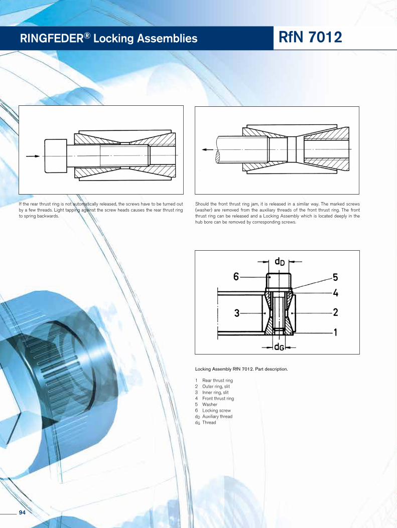
RINGFEDER® Locking Assemblies RfN 7012
If the rear thrust ring is not automatically released, the screws have to be turned out by a few threads. Light tapping against the screw heads causes the rear thrust ring to spring backwards.
Should the front thrust ring jam, it is released in a similar way. The marked screws (washer) are removed from the auxiliary threads of the front thrust ring. The front thrust ring can be released and a Locking Assembly which is located deeply in the hub bore can be removed by corresponding screws.
Locking Assembly RfN 7012. Part description.
1 Rear thrust ring 2 Outer ring, slit3 Inner ring, slit4 Front thrust ring5 Washer 6 Locking screwdD Auxiliary threaddG Thread
94

RfN 7012
Installation and removal instructions
Locking Assembly RfN 7012, RfN 7012 stainless steel
Installation
Since the force is transmitted by contact pressure and fric-tion between functional surfaces, condition of contact sur-faces and proper tightening of the locking screws are of great importance.
1. All contact surfaces, including screw threads and screw head bearing surfaces, must be clean and slightly oiled (Do not use Molybdenum Disulphide!). In this condition, the shaft, hub and Locking Assemblies are to be assembled.
2. Tighten locking screws lightly and align hub.
3. Tighten screws evenly in diametrically opposite sequence and do this in two or three stages up to the indicated ti-ghtening torque TA.
4. Recheck tightening torque by applying it to all screws all the way around. When no screw will turn anymore, the as-sembly is completed.
Removal
Locking Assemblies RINGFEDER® RfN 7012 are not self- locking. The taper of the individual rings is such that the inner and outer rings spring apart. After loosening the last screw the connection is usually disengaged.
The washers under the screws protect the auxiliary (removal) threads against damage.
If relatively great forces are needed to extract a Locking Assembly that has already been loosened (e. g. if the Lock-ing Assembly has to be pushed against the weight of a heavy boss or hub), any type of removal device may be used, but the screws must only be slackened and not screwed out too far. As long as this instruction is followed, there is no objec-tion against the use of a removal device, provided the forces applied are kept low.
The auxiliary threads have only about 3-5 effective courses and are not cut right through. Do not use these holes for jack screws.
Dismount and clean dirty undamaged Locking Assemblies before re-use.
95

Mounting of a Locking Assembly RfN 7013.0
Mounting of a Locking Assembly RfN 7013.1
Removing of a Locking Assembly RfN 7013.0
Removing of a Locking Assembly RfN 7013.1
RINGFEDER® Locking Assemblies RfN 7013
96

RfN 7013
Installation and removal instructions
Locking Assembly RfN 7013.0, RfN 7013.1
Installation
Since the force is transmitted by contact pressure and fric-tion between functional surfaces, condition of contact sur-faces and proper tightening of the locking screws are of great importance.
1. All contact surfaces, including screw threads and screw head bearing surfaces, must be clean and slightly oiled (Do not use Molybdenum Disulphide!). In this condition, the shaft, hub and Locking Assemblies are to be assembled.
2. Tighten locking screws lightly and align hub.
3. Tighten screws evenly in diametrically opposite sequence and do this in two or three stages up to the indicated tightening torque TA.
4. Recheck tightening torque by applying it to all screws all the way around. If all screws have reached the max. tightening torque TA, the assembly is completed.
Removal
The Locking Assemblies RfN 7013 are to be removed in the following sequence:
1. Loosen all screws by a few turns.
2. Remove the screws adjacent to each threaded bore and screw them into these bores pressing off the outer ring. The connection is then released.
3. The connection can be either readjusted or disassembled. Remove the jack screws only after the Locking Assembly has been taken out of the hub.
Dismount and clean dirty undamaged Locking Assemblies before re-use.
97

RINGFEDER® Locking Assemblies RfN 7014
34
2
5 1
dG
Locking Assembly not tightened
Locking Assembly with a screw in one of the release threads
1 Rear thrust ring 2 Outer ring, slit3 Inner ring, slit4 Front thrust ring5 Locking screwdG Thread
98

RfN 7014
Installation and removal instructions
Locking Assembly RfN 7014 Installation
Since the force is transmitted by contact pressure and fric-tion between the functional surfaces, the condition of the contact surfaces and correct tightening of the locking screws are of great importance.
1. When originally packed, Locking Assemblies are fitted with small metal packing pieces located in the slits of the inner and outer rings. These are for shipping purposes only and MUST be removed prior to installation.
2. All contact surfaces, including screw threads and screw head bearing surfaces, must be clean and slightly oiled (Do not use Molybdenum Disulphide!). In this condition, the shaft, hub and Locking Assemblies are to be assembled.
3. Tighten locking screws lightly and align hub.
4. Tighten screws evenly in diametrically opposite sequence and do this in two or three stages up to the indicated final tightening torque TA.
5. Recheck tightening torque by applying it to all the screws. If all screws have reached the max. tightening torque TA, the assembly is completed.
Removal
The Locking Assemblies RfN 7014 are to be removed as follows:
1. Loosen all screws by a few threads.
2. Remove the screws adjacent to each threaded release hole and screw them into these holes. Since the rear thrust ring rests against either shaft or hub shoulder, the jack screws will automatically push apart both tapers, thus releasing the connection.
3. The connection can be either re-adjusted or disassembled. Remove the jack screws only after the Locking Assembly has been taken out of the hub.
Used Locking Assemblies have to be replaced and slightly oiled prior to reinstallation. Note that the release threads of the front thrust ring have to be positioned opposite to undrilled spaces of the rear thrust ring. These threads are used for removal.
99

Figure 2: Removal front thrust ring
Figure 1: Locking Assembly RfN 7015. Part description.
Figure 3: Removal rear thrust ring
RINGFEDER® Locking Assemblies
Figures for RfN 7515 see page 102
RfN 7015/7515
1 Rear thrust ring 2 Outer ring, slit3 Inner ring, slit4 Front thrust ring5 Locking screwdG Thread
Figures for RfN 7015
100

Installation and removal instructions
Locking Assembly RfN 7015.0, 7015.1, 7515 Installation
Since the force is transmitted by contact pressure and fric-tion between functional surfaces, condition of contact sur-faces and proper tightening of the locking screws are of great importance (see point 1).
1. All contact surfaces, including screw threads and screw head bearing surfaces, must be clean and slightly oiled (Do not use Molybdenum Disulphide!). In this condition, the shaft, hub and Locking Assemblies are to be assembled.
1.1 Unscrew all locking screws far enough so that only few threads are engaged in the rear thrust ring. For shipping purposes, these screws have been screwed in quite deep.
1.2 With larger Locking Assemblies, it is advantageous to insert several locking screws into the corresponding threads of the front thrust ring according to Fig. 2 and push against them.
2. After the Locking Assembly is placed in position, slightly tighten all locking screws (screwed into the rear thrust ring) and make final alignment and adjustment of the con- nection.
3. Tighten screws evenly in diametrically opposite se- quence and do this in two or three steps up to the indicated tightening torque TA.
4. Recheck tightening torque by applying it to all screws all the way around. If all screws have reached the max. tightening torque TA, the assembly is completed.
Used Locking Assemblies have to be cleaned and slightly oiled prior to installation and re-assembled according to Fig. 1
When reassembling, it is important to make sure that all threaded holes of the rear thrust ring (1) are in line with the holes in web of inner ring (3) and front thrust ring (4). Threaded removal holes in front thrust ring must be located opposite blanc spaces in web of inner ring, and the threaded removal holes in web of inner ring must be located opposite blanc spaces of rear thrust ring, see Fig. 1.
RfN 7015/7515101
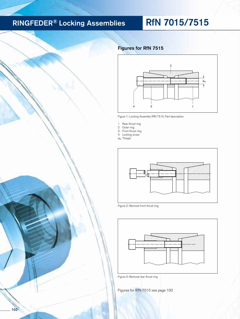
dG
134
2
Figure 1: Locking Assembly RfN 7515. Part description.
RINGFEDER® Locking Assemblies RfN 7015/7515
Figure 2: Removal front thrust ring
Figure 3: Removal rear thrust ring
Figures for RfN 7015 see page 100
1 Rear thrust ring 2 Outer ring3 Front thrust ring4 Locking screwdG Thread
Figures for RfN 7515
102

RfN 7015/7515
Locking Assembly RfN 7015.0, 7015.1, 7515
Removal
The Locking Assemblies RfN 7015 are to be removed as follows:
1. Loosen all screws by a few turns.
2. Remove the screws adjacent to each threaded bore and screw them into these bores.
2.1 The front thrust ring is released by having the jack screws pressed against the web of the inner ring (see Fig. 2).
2.2 The rear thrust ring is released by having the jack screws inserted in the threaded bore of the inner ring web and thus pushing it out (Fig. 3).
3. Pull or push hub and Locking Assemblies off the shaft. The jack screws should be removed only after the Locking Assembly has been taken out of the hub.
Disassemble and clean dirty, undamaged Locking Assemblies before re-use.
Installation and removal instructions
103

A
A
RINGFEDER® Locking Assemblies RfN 7061stainless steel
Fogure 1: Mounting of a Locking Assembly RfN 7061
Figure 2: Removal of a Locking Assembly RfN 7061
104

RfN 7061
Installation and removal instructions
Locking Assembly RfN 7061 stainless steel
Installation
Since the force is transmitted by contact pressure and friction between functional surfaces, the condition of the contact surfaces and proper tightening of the locking screws are of great importance (see point 1).
1. All contact surfaces, including screw threads and screw head bearing surfaces, must be clean and slightly oiled (Do not use Molybdenum Disulphide!). In this condition, the shaft, hub and Locking Assemblies are to be assembled.
2. Tighten locking screws lightly and align hub.
3. Tighten screws evenly in diametrically opposite sequence and do so in two or three steps up to the indicated tightening torque.
4. Recheck tightening torque by applying it to all screws all the way around. If all screws have reached the max. tightening torque TA, the assembly is completed.
Removal
The Locking Assemblies RfN 7061 are to be removed in the following sequence:
1. Loosen all screws by a few turns.
2. Remove the screws adjacent to each threaded jacking hole and screw them into these bores.
3. Tighten the jacking screws, starting with the positions furthest away from the slit first, in several steps until the connection is released.
4. The connection can then either be readjusted or disas- sembled. Remove the jacking screws only after the Locking Assembly has been removed from the hub.
Dismount and clean dirty undamaged Locking Assemblies before re-use and slightly oil them as described in point 1 of the mounting instructions.
105

This connection is shown in mounted condition. During mounting, the V-belt pulley is supported by the spacer bushing at the inner ring of the Locking Assembly RfN 7110 and thus also stays axially clearly positioned.
Bevel gear mounted with one Locking Assembly RfN 7110. During mounting the axial position of the bevel gear remains unchanged.
RINGFEDER® Locking Assemblies RfN 7110stainless steel
106

RfN 7110
Installation and removal instructions
Locking Assembly RfN 7110 stainless steel
Installation Since the force is transmitted by contact pressure and friction between functional surfaces, the condition of the contact surfaces and proper tightening of the locking screws are of great importance (see point 1).
1. All contact surfaces, including screw threads and screw head bearing surfaces, must be clean and slightly oiled (Do not use Molybdenum Disulphide!). In this condition, the shaft, hub and Locking Assemblies are to be assembled.
2. Tighten locking screws lightly and align hub.
3. Tighten screws evenly in diametrically opposite sequence and do so in two or three steps up to the indicated tightening torque.
4. Recheck tightening torque by applying it to all screws all the way around. If all screws have reached the max. tightening torque TA, the assembly is completed.
Removal
The Locking Assemblies RfN 7110 are to be removed in the following sequence:
1. Loosen all screws by a few turns.
2. Remove the screws adjacent to each threaded jacking hole and screw them into these bores.
3. Tighten the jacking screws, starting with the positions furthest away from the slit first, in several steps until the con- nection is released.
4. The connection can then either be readjusted or disas- sembled. Remove the jacking screws only after the Locking Assembly has been removed from the hub.
Dismount and clean dirty undamaged Locking Assemblies before re-use and slightly oil them as described in point 1 of the mounting instructions.
107

Tightening of the locking screws and distance x
Locking Element RfN 8006 · View and section
RINGFEDER® Locking Elements RfN 8006
108

RfN 8006
Installation and removal instructions
Since the force is transmitted by contact pressure and friction between functional surfaces, condition of contact surfaces and proper tightening of the lo-cking screws are of great importance (see point 1).
Installation
1. All contact surfaces, including screw threads and screw head contact surface, must be clean and slightly oiled.
2. Fit the parts in the following order: A = Hub Insert the Locking Element rings (B) according to the
assembly drawing (both parts must be easy to install and must not jam under any circumstances).
C = Insert compression flange (distance sleeve if necessary) or compression flange with collar. Ensure that both parts are easy to move.
D = Locking screws Carefully oil the locking screws before fitting. This applies in particular to the screw head seat. ATTENTION: Do not use Molybdenum Disulphide! The screws must turn easily and to an adequate depth. Do not use spring washers or serrated locking washers.
3. Tighten locking screws lightly and align hub.
4. Tighten screws evenly in diametrically opposite sequence and do this with a torque wrench in several stages up to the indicated tightening torque ( TA) .
5. Recheck tightening torque by applying it to all screws all the way around. If all screw have reached the max. tightening torque TA , the assembly is completed.
6. Check distance x: The thrust ring must never contact the face of the hub.
The gap between thrust ring and hub face should be as uniform as possible.
Removal
1. Loosen all screws one after the other in several steps.
2. Remove the flange.
3. Take out the Locking Elements – the Locking Elements release automatically after the screws have been loosened. If not, light tapping is enough to start the releasing process.
109

Online Service
In order to meet the complex requirements on the correct design and selection of RINGFEDER® products under practise-relevant demands, RINGFEDER POWER TRANSMISSION GMBH has de-veloped a calculation program.
This calculation program offers the engineer a valuable aid in his or her daily work and simplifies the calculation of a wide range of tasks.
Once a product and the desired product size have been selected the program carries out the calculation, taking into account additional user input e.g. transmissible torque and axial forces, resulting hub and shaft pressure, the outer diameter of the hub, the inner diameter of the hollow shaft and for special tasks even the forces and loads under bending moment loads.
Interested? Visit our Website at www.ringfeder.com!
Calculation program for Locking Assemblies and Locking Elements
110

www.ringfeder.com
Our WebsiteEasily accessible information. RINGFEDER POWER TRANSMISSION – one of the top addresses for drive and damping technology in mechanical engineering. You can find first-hand service details and informa-tion on our website. It contains both details on our entire range of products and numerous documents such as product catalo-gues, data sheets and assembly instruction for you to download. Visit www.ringfeder.com to get right up to date.
Available instructions for Installation, Removal and Maintaining
Download area Product Range and catalogues
111
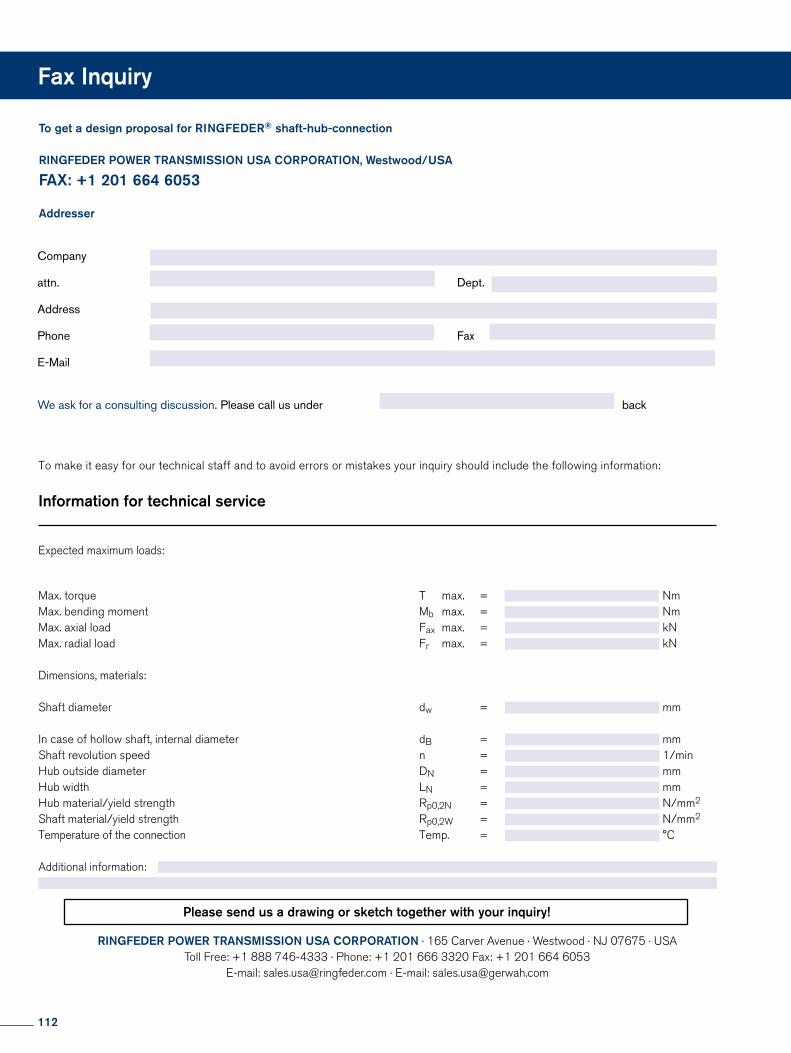
To get a design proposal for RINGFEDER® shaft-hub-connection
RINGFEDER POWER TRANSMISSION USA CORPORATION, Westwood/USA
FAX: +1 201 664 6053 Addresser
Company
attn. Dept.
Address
Phone Fax
We ask for a consulting discussion. Please call us under back
RINGFEDER POWER TRANSMISSION USA CORPORATION · 165 Carver Avenue · Westwood · NJ 07675 · USA Toll Free: +1 888 746-4333 · Phone: +1 201 666 3320 Fax: +1 201 664 6053
E-mail: [email protected] · E-mail: [email protected]
To make it easy for our technical staff and to avoid errors or mistakes your inquiry should include the following information:
Information for technical service
Expected maximum loads:
Max. torque T max. = NmMax. bending moment Mb max. = NmMax. axial load Fax max. = kNMax. radial load Fr max. = kN
Dimensions, materials:
Shaft diameter dw = mm
In case of hollow shaft, internal diameter dB = mmShaft revolution speed n = 1/minHub outside diameter DN = mmHub width LN = mmHub material/yield strength Rp0,2N = N/mm2
Shaft material/yield strength Rp0,2W = N/mm2
Temperature of the connection Temp. = °C
Additional information:
Please send us a drawing or sketch together with your inquiry!
Fax Inquiry
112

113

Locking Devices
Locking Assemblies
Locking Elements
Special Solutions
Damping Technology
Locking Assemblies – Stainless steel
Locking Assemblies for ben-ding moments
Shrink Discs
Friction Springs DEFORM plus® RDEFORM plus®
Locking Assemblies
Flange Couplings
Shaft Couplings
RINGFEDER POWER TRANSMISSION
114

Locking Devices
Locking Assemblies
Locking Elements
Special Solutions
Damping Technology
Locking Assemblies – Stainless steel
Locking Assemblies for ben-ding moments
Shrink Discs
Friction Springs DEFORM plus® RDEFORM plus®
Locking Assemblies
Flange Couplings
Shaft Couplings
RINGFEDER POWER TRANSMISSION
Couplings
Servo-Insert CouplingsMetal Bellows Couplings
Line Shafts Torsionally Rigid Disc Couplings
Safety Couplings
Couplings
Torsionally Flexible Couplings Torsionally Flexible CouplingsTorsionally Flexible Couplings
Torsionally Rigid Gear Couplings Torsionally Rigid Barrel Coupling Couplings with variable Stiffness
Partner for Performance
115

www.ringfeder.comRINGFEDER POWER TRANSMISSION
RINGFEDER POWER TRANSMISSION GMBHWerner-Heisenberg-Straße 18, D-64823 Groß-Umstadt, Germany · Phone: +49 (0) 6078 9385-0 · Fax: +49 (0) 6078 9385-100 E-mail: [email protected]
RINGFEDER POWER TRANSMISSION TSCHAN GMBHZweibrücker Strasse 104, D-66538 Neunkirchen, Germany · Phone: +49 (0) 6821 866-0 · Fax: +49 (0) 6821 866-4111 E-mail: [email protected]
RINGFEDER POWER TRANSMISSION USA CORPORATION165 Carver Avenue, Westwood, NJ 07675, USA · Toll Free: +1 888 746-4333 · Phone: +1 201 666 3320Fax: +1 201 664 6053 · E-mail: [email protected]
HENFEL INDÚSTRIA METALÚRGICA LTDA.Av. Major Hilário Tavares Pinheiro, 3447 · Cer 14871 300 · Jaboticabal - SP - Brazil · Phone: +55 16 3209-3422Fax: +55 16 3202-3563 · E-mail: [email protected]
RINGFEDER POWER TRANSMISSION INDIA PRIVATE LIMITEDPlot No. 4, Door No. 220, Mount - Poonamallee Road, Kattupakkam, Chennai – 600 056, IndiaPhone: +91 (0) 44-2679 1411 · Fax: +91 (0) 44-2679 1422 · E-mail: [email protected]
KUNSHAN RINGFEDER POWER TRANSMISSION COMPANY LIMITEDNo. 10 Dexin Road, Zhangpu Town 215321, Kunshan, ChinaPhone: +86 (0) 512-5745-3960 · Fax: +86 (0) 512-5745-3961 · E-mail: [email protected]