01/2014 technical information mdt knx rf+ - knx-mdt.grknx-mdt.gr/mdt/data/m31_rf+_eng.pdfthe knx rf+...
TRANSCRIPT

MDT technologies GmbH • 51766 Engelskirchen • Papiermühle 1
Tel.: +49-2263-880 • Fax: +49-2263-4588 • [email protected] • www.mdt.de
01/2014
Technical Information
MDT KNX RF+

Technisches Informationen MDT KNX RF+
MDT technologies GmbH • 51766 Engelskirchen • Papiermühle 1
Tel.: +49-2263-880 • Fax: +49-2263-4588 • [email protected] • www.mdt.de 2
2
1 Content 1 Content ................................................................................................................................................. 2
2 Introduction .......................................................................................................................................... 3
3 Functionality of KNX RF+ ...................................................................................................................... 4
4 Topology RF+ TP .................................................................................................................................. 5
4.1 Overview ........................................................................................................................................ 5
4.2 Components .................................................................................................................................. 6
4.3 Installation & Planning .................................................................................................................. 7
4.3.1 Basic information for broadening .......................................................................................... 7
4.3.2 Range of Radio signals ............................................................................................................ 9
4.3.3 Conclusion for mounting ...................................................................................................... 10
4.3.4 Recommended mounting in buildings ................................................................................. 13
4.4 Settings in the ETS ....................................................................................................................... 15
4.4.1 Installation of the project ..................................................................................................... 15
4.4.2 Approach at startup.............................................................................................................. 17
5 Index ................................................................................................................................................... 19
5.1 List of Illustrations ....................................................................................................................... 19
5.2 List of tables................................................................................................................................. 19

Technisches Informationen MDT KNX RF+
MDT technologies GmbH • 51766 Engelskirchen • Papiermühle 1
Tel.: +49-2263-880 • Fax: +49-2263-4588 • [email protected] • www.mdt.de 3
3
2 Introduction By introducing the new KNX RF+ Devices, the improvement of accommodation or back fittings becomes much easier and is possible without chiseling. So every building can benefit from the modern KNX bus system. The new KNX RF+ Push Buttons/ Glass Push Buttons with integrated actuator replace conventional push buttons/ switches and can be connected to the KNX bus system via the KNX RF+ Line Coupler. The KNX RF+ Devices are connected to the bus system KNX via the RF+ Line Coupler. By coupling KNX RF+ and KNX TP (Twisted Pair), a lot of advantages are offered:
No chiseling work necessary
Easy, fast back fitting and modernization von buildings in use
Using of the variety of TP-devices from every manufacturer
Parameterization of the KNX RF+ Devices via ETS
Easy replacement of conventional switches by KNX RF+ push buttons with integrated actuator (neutral conductor necessary)
The RF+ Line Coupler operates like a normal Line Coupler
Supplying of the RF+ Devices from the 230V Grid (no batteries)
Every device can work as Repeater
Technisches Informationen MDT KNX RF+
MDT technologies GmbH • 51766 Engelskirchen • Papiermühle 1
Tel.: +49-2263-880 • Fax: +49-2263-4588 • [email protected] • www.mdt.de 4
4
3 Functionality of KNX RF+ The physical transmission behavior of KNX RF+ is specified to EU-Rules for short distance devices. It works with a center frequency of 868.3MHz. The data transmission happens by variation of the frequency by +- 50 kHz, the so called FSK-modulation. The frequency band of 868Mhz is especially useful for the communication in buildings, because the transmission capacity is much lower than e.g. WLAN due to the lower frequency. The short KNX telegrams are still transmitted safely and fast. The maximum of the transmission distance is 150m at the open air test site. In buildings, the transmission path depends to the situation and the assembly. Realistic Reaches can be extracted or calculated from the chapter 4.3 Installation & . All MDT RF+ Devices communicate by the new KNX RF+ protocol in System mode. The new protocol is similar to the existing Twisted Pair protocol and addresses its communication partner directly via group addresses. So a transfer from serial number addressing to group address addressing via additional gateway is no longer necessary. The assignment of the devices to their lines is done by Domain-Address. So extensive databases, like normal TP-devices, can be transmitted to the RF+ Devices – in contrast to existing KNX RF standards. The RF+ Line Coupler connects KNX RF+ Lines with KNX TP Lines. RF+ Devices in one line can communicate completely on their own without any additional Repeater or Gateway. So the RF+ Line Coupler is only for the connection from KNX RF+ to KNX TP and vice versa. Safety notes: RF+ runs on a Sub line, which is separated from the TP main line by a filtering table such as the outdoor line at a normal Line Coupler. The RF+ Line Coupler controls, via the filtering table, which telegrams are forwarded from RF+ to TP and vice versa. Group addresses which open doors or garage doors should not be controlled via RF! RF+ uses an extended Group Address which also contains the Domain Address of the RF+ line. So it is not possible to send telegrams from another RF+ line into this line.

Technisches Informationen MDT KNX RF+
MDT technologies GmbH • 51766 Engelskirchen • Papiermühle 1
Tel.: +49-2263-880 • Fax: +49-2263-4588 • [email protected] • www.mdt.de 5
5
4 Topology RF+ TP
4.1 Overview The following illustration shows an overview, how an integration of KNX RF+ Devices to an existing KNX installation can look like:
Figure 1: Overview Topology
The topology at the installation of KNX RF+ Devices is in principle the same as using normal TP Devices. For coupling the TP line to the RF+ line, a KNX RF+ Line Coupler is necessary. Every TP Line must have an own bus power supply. There is no limitation of 64 devices per line. At KNX RF+, only the bus load at the radio-channel is the limitation for the size of installations. The MDT RF+ Devices work without battery and can be connected directly to 230V AC.

Technisches Informationen MDT KNX RF+
MDT technologies GmbH • 51766 Engelskirchen • Papiermühle 1
Tel.: +49-2263-880 • Fax: +49-2263-4588 • [email protected] • www.mdt.de 6
6
4.2 Components For every connection from KNX with Radio a KNX RF+ Line Coupler is necessary. The communication between the devices is directly, that means it does not go the detour via the Line Coupler. So KNX RF+ can also work without Line Coupler. Only for the programming and the coupling with TP devices, the KNX RF+ Line Coupler is necessary. The following MDT KNX RF+ Devices are at the moment available:
KNX RF+ Line Coupler: RF-LK001.01 o for connecting a TP(Twisted-Pair) and a RF+ line o supplied from the KNX bus
KNX RF+ Glass Push Buttons o Push Buttons in modern glass appearance with RF+ communication o LED-lighting and extensive logic options o as 4-fold or 8-fold push button in black or white available o with integrated actuator, which can be adjusted as switching output or shutter
output o also with integrated temperature sensor available o Power supply: 230V AC (neutral conductor necessary)
KNX RF+ Push Button o Standard Push Button with LED-lightning and extensive logic options o also with integrated actuator available, which can be adjusted as switching output or
as shutter output o Power supply: 230V AC (neutral conductor necessary)
KNX RF+ Switch actuator o as 1-fold or 2-fold switch actuator available o flush-mounted o Power supply: 230V AC (neutral conductor necessary)
KNX RF+ Shutter actuator o Shutter actuator flush mounting with RF+ communication o Power supply: 230V AC (neutral conductor necessary)
KNX RF+ Socket o RF-Socket for the easy integration of normal sockets into the KNX-Network o Also with active power measurement available
The detailed specifications and descriptions of the devices can be seen in the actual pricelist at http://www.mdt.de/download/MDT_Pricelist.pdf.

Technisches Informationen MDT KNX RF+
MDT technologies GmbH • 51766 Engelskirchen • Papiermühle 1
Tel.: +49-2263-880 • Fax: +49-2263-4588 • [email protected] • www.mdt.de 7
7
4.3 Installation & Planning
4.3.1 Basic information for broadening Electromagnetic waves are the information carrier for the radio transmission. The broadening of the electromagnetic waves is circular respectively ellipsoidal:
Figure 2: Broadening of electromagnetic waves
As shown at the upper illustration, the electromagnetic wave broadens circular from its radio transmitter. The strength of the lines demonstrates the signal strength. This is reduced quadratic to the distance from the transmitter. If the signal strength is in the nominal range at the distance x, it will be reduced by 1/4 at a distance of 2x and 1/16 at a distance of 4x. Thereby, the broadening of the electromagnetic waves is much better in the direction of mounting than backwards. Additional barriers like walls can weaken the signal strength:

Technisches Informationen MDT KNX RF+
MDT technologies GmbH • 51766 Engelskirchen • Papiermühle 1
Tel.: +49-2263-880 • Fax: +49-2263-4588 • [email protected] • www.mdt.de 8
8
Figure 3: Broadening of electromagnetic waves with barriers
The upper image shows that an electromagnetic wave is weakened by every interfuse of a wall additional to the normal approval by distance. At this example, it is act on the assumption of solid walls of cement. Here a decrease occurs with every pass through a wall, so the signal strength is already decimated after the second wall(shown by the dashed lines).

Technisches Informationen MDT KNX RF+
MDT technologies GmbH • 51766 Engelskirchen • Papiermühle 1
Tel.: +49-2263-880 • Fax: +49-2263-4588 • [email protected] • www.mdt.de 9
9
4.3.2 Range of Radio signals As described in the chapter before, the signal strength is weakened by barriers. Thereby different material have different absorptions. Consecutively some examples of different materials:
Material Range reduction in opposite to free field
Wooden Wall, sheetrock wall, glass (without metal)
0-10%
Stone wall, Wall of press board 5-35%
Cement with reinforcement of iron 10-90%
Metal, Alu (Underfloor heating Alu) almost complete barrier Table 1: Reduction of range
Furthermore the geometric figure of the room is essential for the broadening of the electromagnetic waves. So a waves has its best characteristics in almost quadratic, big rooms. A bad broadening can be observed in long, tighten rooms as corridors. This is founded in the circular broadening of electromagnetic waves ( have a look at: 4.3.1 ). What can we say now about the realistic range of the radio communication? The Range of radio signals in buildings is often specified with 30m. But because of the normal absorption in buildings, this statement must be proofed in every case. The following chart gives a approximated guide line for planning the range of radio signals:
about 30m at good requirements: Big free room, good mounting position of the transmitter and almost no disturbance sources in the radio transmission channel, e.g. big conference
Planning reliability: o about 20m with persons in the room and transmission through some
sheetrock walls or up to 2 stone walls o about 10m in tighten corridors
Vertical passage of ceilings must be proofed in every case Table 2: Practical values for the maximum range
Metal areas reflect the electromagnetic wave. Due to repeatedly reflection (at every barrier a piece of the electromagnetic waves is reflected back) a radio transmission can also work in such an environment. But in such a case significant limitations must be anticipated. In contrast, single metal parts or metal strips have almost no influence to the signal strength. By selective positioning of the transmitter, many barriers can be avoided and dead zone can be avoided (have a look at 4.3.3 ).

Technisches Informationen MDT KNX RF+
MDT technologies GmbH • 51766 Engelskirchen • Papiermühle 1
Tel.: +49-2263-880 • Fax: +49-2263-4588 • [email protected] • www.mdt.de 10
10
4.3.3 Conclusion for mounting For the mounting of the devices can be concluded, that a vertical angle of intersection through walls and other barriers would be ideal. Furthermore the range of radio signals can be increased by positioning transmitter and receiver not in the dead zone of barriers:
Figure 4: Dead zone of barriers
The upper illustration shows the effect of a barrier to the transmission path. So, a radio signal cannot be transmitted certainly, when a barrier is in the function line of the transmission path. Repositioning the device from place 1(Receiver 1) to place 2 (Receiver 2) can correct this problem. The placement of the dead zone behind a barrier can be seen at the following picture:
Figure 5: Calculation dead zone
Technisches Informationen MDT KNX RF+
MDT technologies GmbH • 51766 Engelskirchen • Papiermühle 1
Tel.: +49-2263-880 • Fax: +49-2263-4588 • [email protected] • www.mdt.de 11
11
Barriers, which can create such a dead zone, are:
Metal walls
Cavity walls with insulation on metal film
Ceilings with panels of metal or carbon fiber
Furniture made of steel
Glass with metal cover Other reasons for range reductions are:
Mounting a switch on a metal wall
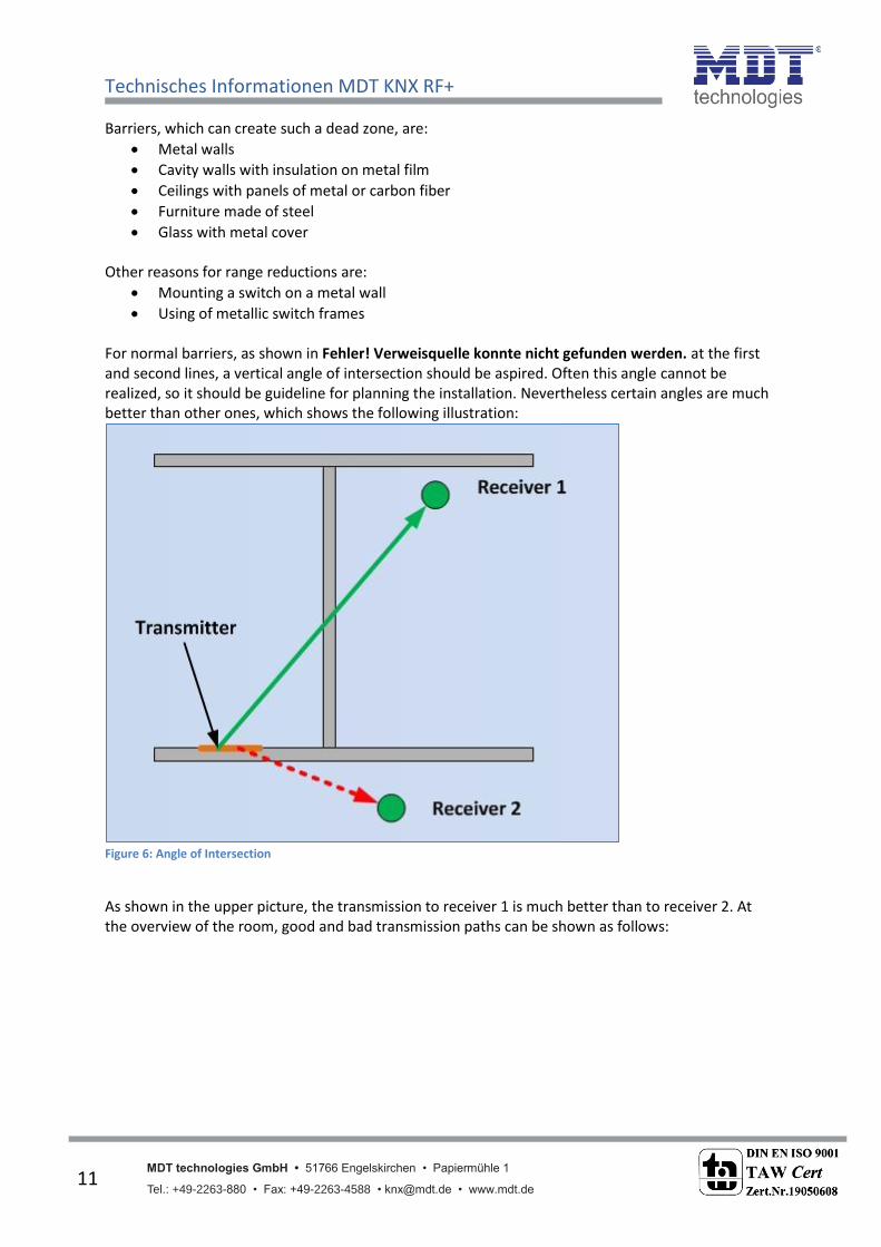
Using of metallic switch frames For normal barriers, as shown in Fehler! Verweisquelle konnte nicht gefunden werden. at the first and second lines, a vertical angle of intersection should be aspired. Often this angle cannot be realized, so it should be guideline for planning the installation. Nevertheless certain angles are much better than other ones, which shows the following illustration:
Figure 6: Angle of Intersection
As shown in the upper picture, the transmission to receiver 1 is much better than to receiver 2. At the overview of the room, good and bad transmission paths can be shown as follows:

Technisches Informationen MDT KNX RF+
MDT technologies GmbH • 51766 Engelskirchen • Papiermühle 1
Tel.: +49-2263-880 • Fax: +49-2263-4588 • [email protected] • www.mdt.de 12
12
Figure 7: Installation in the overview
As shown in the overview of the room, two transmitter/receiver should not be placed on a line, when they shall communicate with each other. All in all the following mounting guideline can be formulated:
a vertical intersection angle should be targeted
no metal barriers should be placed in the transmission path
transmitter and receiver should not be on a line and placed in the optimum in vertical angle
im Funkübertragungsweg sollten sich keine Metall-Abschottungen befinden
transmitter and receiver should be mounted a the middle of the room or in the middle of the room at mounting on the ceiling, because of the circular broadening of the radio signals
devices should not be mounted near source of disturbances like computer, audio or video equipment, electronic control gears for
Important at this considerations is, that these facts are the aspired state. Also at a not ideal mounting, a good communication is possible. But it should be considered, that not more than one aspect of the guideline is disregarded at once. Furthermore the radio transmission should be proofed at a not ideal mounting before commissioning.
Technisches Informationen MDT KNX RF+
MDT technologies GmbH • 51766 Engelskirchen • Papiermühle 1
Tel.: +49-2263-880 • Fax: +49-2263-4588 • [email protected] • www.mdt.de 13
13
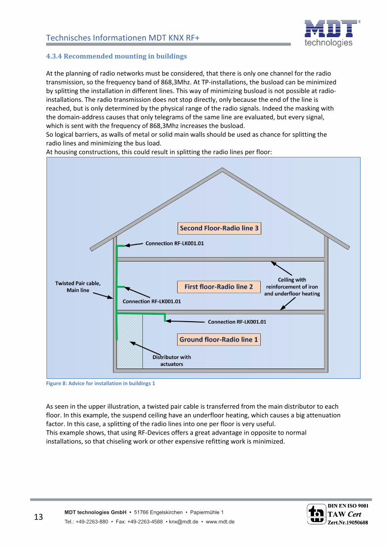
4.3.4 Recommended mounting in buildings At the planning of radio networks must be considered, that there is only one channel for the radio transmission, so the frequency band of 868,3Mhz. At TP-installations, the busload can be minimized by splitting the installation in different lines. This way of minimizing busload is not possible at radio-installations. The radio transmission does not stop directly, only because the end of the line is reached, but is only determined by the physical range of the radio signals. Indeed the masking with the domain-address causes that only telegrams of the same line are evaluated, but every signal, which is sent with the frequency of 868,3Mhz increases the busload. So logical barriers, as walls of metal or solid main walls should be used as chance for splitting the radio lines and minimizing the bus load. At housing constructions, this could result in splitting the radio lines per floor:
Figure 8: Advice for installation in buildings 1
As seen in the upper illustration, a twisted pair cable is transferred from the main distributor to each floor. In this example, the suspend ceiling have an underfloor heating, which causes a big attenuation factor. In this case, a splitting of the radio lines into one per floor is very useful. This example shows, that using RF-Devices offers a great advantage in opposite to normal installations, so that chiseling work or other expensive refitting work is minimized.

Technisches Informationen MDT KNX RF+
MDT technologies GmbH • 51766 Engelskirchen • Papiermühle 1
Tel.: +49-2263-880 • Fax: +49-2263-4588 • [email protected] • www.mdt.de 14
14
If the apartment house has „permeable” ceilings, e.g. made of wood, it will be also possible to use only one Line Coupler:
Figure 9: Advice for installation in buildings 1
In this case, the Line Coupler should be placed in the middle of the room for reaching every area of the house. In every case, the range of the radio signals should be proofed at a new installation and must be adapted if necessary or the Repeater function some devices must be activated.

Technisches Informationen MDT KNX RF+
MDT technologies GmbH • 51766 Engelskirchen • Papiermühle 1
Tel.: +49-2263-880 • Fax: +49-2263-4588 • [email protected] • www.mdt.de 15
15
4.4 Settings in the ETS
4.4.1 Installation of the project The project is identical with projects with Twisted Pair Line Coupler, but every connection from TP to radio can only be realized by using the Line Coupler RF-LK001.01. Our example has the following topology:
Figure 10: Topology Example
At the ETS, the topology looks like this:
Figure 11: Topology ETS
Technisches Informationen MDT KNX RF+
MDT technologies GmbH • 51766 Engelskirchen • Papiermühle 1
Tel.: +49-2263-880 • Fax: +49-2263-4588 • [email protected] • www.mdt.de 16
16
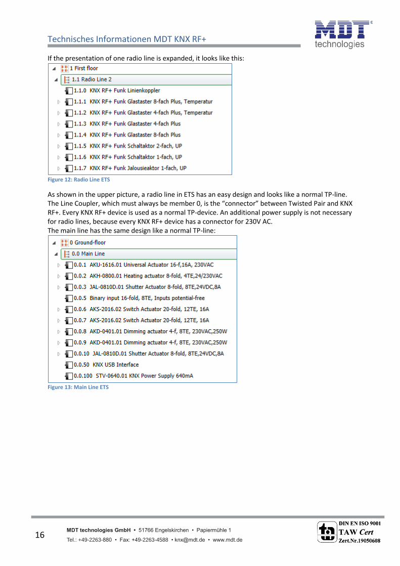
If the presentation of one radio line is expanded, it looks like this:
Figure 12: Radio Line ETS
As shown in the upper picture, a radio line in ETS has an easy design and looks like a normal TP-line. The Line Coupler, which must always be member 0, is the “connector” between Twisted Pair and KNX RF+. Every KNX RF+ device is used as a normal TP-device. An additional power supply is not necessary for radio lines, because every KNX RF+ device has a connector for 230V AC. The main line has the same design like a normal TP-line:
Figure 13: Main Line ETS

Technisches Informationen MDT KNX RF+
MDT technologies GmbH • 51766 Engelskirchen • Papiermühle 1
Tel.: +49-2263-880 • Fax: +49-2263-4588 • [email protected] • www.mdt.de 17
17
4.4.2 Approach at startup After all devices are integrated in the project, appropriate the right topology like described in 4.4.1 , the devices can be parameterized according to the own wishes. It is recommended to use the RF-LK001.01 with the default settings. The right course of action at the startup is very important, because otherwise the exchange of data between TP and radio cannot be guaranted.
1. Programming the Line Coupler By programming the Line Coupler, the current settings are load into the Line Coupler. Furthermore the current Filter table is loaded into the Line Coupler. A preview of the current Filter table can be seen as follows:
Figure 14: Preview Filter table
For that purpose, you click with the right mouse button at the Line Coupler. Now you can choose the entry “Preview Filter table…” in the context menu. The Filter table shows every group address, which will be transmitted from TP to radio and vice versa:
Figure 15: Preview Filter table 2

Technisches Informationen MDT KNX RF+
MDT technologies GmbH • 51766 Engelskirchen • Papiermühle 1
Tel.: +49-2263-880 • Fax: +49-2263-4588 • [email protected] • www.mdt.de 18
18
2. Programming of the MDT RF+ Devices By programming the KNX RF+ Devices the parameter settings are load in the memory of the devices. This procedure is the same at radio devices as at TP-devices. Furthermore the programming of the KNX RF+ devices writes the domain address into the KNX RF+ devices. This domain address is unique for each line and guarantees that all device of a line can communicate with each other, but devices out of the lines does not disturb this devices.
Important: At every change of the project, the Line Coupler must be load again(Download Application). Afterwards every device, which is changed, must be programmed again. If Changes at the topology of the project are made, at first the Line Coupler must be downloaded and afterwards every device, which is involved of the change of the topology, must be downloaded again.

Technisches Informationen MDT KNX RF+
MDT technologies GmbH • 51766 Engelskirchen • Papiermühle 1
Tel.: +49-2263-880 • Fax: +49-2263-4588 • [email protected] • www.mdt.de 19
19
5 Index
5.1 List of Illustrations Figure 1: Overview Topology ................................................................................................................... 5 Figure 2: Broadening of electromagnetic waves ..................................................................................... 7 Figure 3: Broadening of electromagnetic waves with barriers ............................................................... 8 Figure 4: Dead zone of barriers ............................................................................................................. 10 Figure 5: Calculation dead zone ............................................................................................................ 10 Figure 6: Angle of Intersection .............................................................................................................. 11 Figure 7: Installation in the overview .................................................................................................... 12 Figure 8: Advice for installation in buildings 1 ...................................................................................... 13 Figure 9: Advice for installation in buildings 1 ...................................................................................... 14 Figure 10: Topology Example ................................................................................................................ 15 Figure 11: Topology ETS ........................................................................................................................ 15 Figure 12: Radio Line ETS ...................................................................................................................... 16 Figure 13: Main Line ETS ....................................................................................................................... 16 Figure 14: Preview Filter table .............................................................................................................. 17 Figure 15: Preview Filter table 2 ............................................................................................................ 17
5.2 List of tables Table 1: Reduction of range .................................................................................................................... 9 Table 2: Practical values for the maximum range ................................................................................... 9