0071455914_ar027
TRANSCRIPT

CHAPTER 8.3UOP UNIONFINING
TECHNOLOGY
Peter KokayeffUOP LLC
Des Plaines, Illinois
INTRODUCTION
Hydrotreating is one of the most mature technologies found in the refinery, rivaling the his-tory and longevity of the thermal process. In 1952, UOP and Union Oil Co. of Californiabegan licensing hydrotreating under the name of the Unifining process. The partnershipsand the development of this technology have gone through a series of changes over theyears, and in 1995 the acquisition of the Unocal Process Technology and Licensing groupby UOP resulted in the merger of two premier hydroprocessing companies and the com-bination of their expertise under the UOP* Unionfining* banner.
Generally speaking, the hydrotreating process removes objectionable materials frompetroleum distillates by selectively reacting these materials with hydrogen in a catalyst bedat elevated temperature. These objectionable materials include sulfur, nitrogen, olefins,and aromatics. Lighter materials such as naphtha are generally treated for subsequent pro-cessing in catalytic reforming units, and the heavier distillates, ranging from jet fuel toheavy vacuum gas oils, are treated to meet strict product-quality specifications or for useas feedstocks elsewhere in the refinery. Many of the product-quality specifications aredriven by environmental regulations that are becoming more stringent each year. This pushtoward more environmentally friendly products is resulting in the addition of hydropro-cessing units in refineries throughout the world.
PROCESS CHEMISTRY
The chemistry behind the hydrotreating process can be divided into a number of reactioncategories: (hydro)desulfurization, (hydro)denitrification, saturation of olefins, and satura-tion of aromatics. For each of these reactions, hydrogen is used to improve the quality ofthe petroleum fraction.
8.31
*Trademark and/or service mark of UOP.
Source: HANDBOOK OF PETROLEUM REFINING PROCESSES
Downloaded from Digital Engineering Library @ McGraw-Hill (www.digitalengineeringlibrary.com)Copyright © 2004 The McGraw-Hill Companies. All rights reserved.
Any use is subject to the Terms of Use as given at the website.
Desulfurization
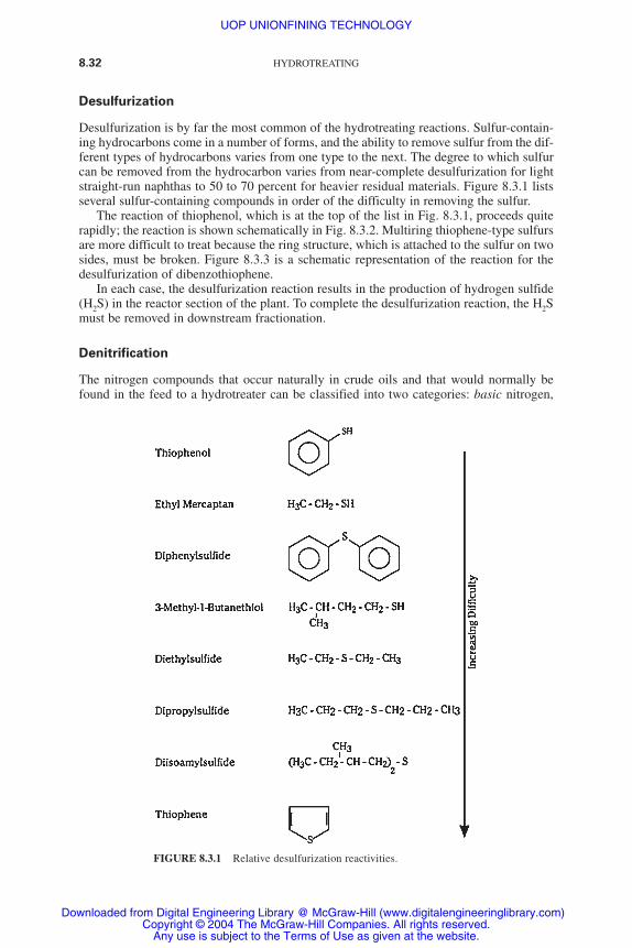
Desulfurization is by far the most common of the hydrotreating reactions. Sulfur-contain-ing hydrocarbons come in a number of forms, and the ability to remove sulfur from the dif-ferent types of hydrocarbons varies from one type to the next. The degree to which sulfurcan be removed from the hydrocarbon varies from near-complete desulfurization for lightstraight-run naphthas to 50 to 70 percent for heavier residual materials. Figure 8.3.1 listsseveral sulfur-containing compounds in order of the difficulty in removing the sulfur.
The reaction of thiophenol, which is at the top of the list in Fig. 8.3.1, proceeds quiterapidly; the reaction is shown schematically in Fig. 8.3.2. Multiring thiophene-type sulfursare more difficult to treat because the ring structure, which is attached to the sulfur on twosides, must be broken. Figure 8.3.3 is a schematic representation of the reaction for thedesulfurization of dibenzothiophene.
In each case, the desulfurization reaction results in the production of hydrogen sulfide(H2S) in the reactor section of the plant. To complete the desulfurization reaction, the H2Smust be removed in downstream fractionation.
Denitrification
The nitrogen compounds that occur naturally in crude oils and that would normally befound in the feed to a hydrotreater can be classified into two categories: basic nitrogen,
8.32 HYDROTREATING
FIGURE 8.3.1 Relative desulfurization reactivities.
UOP UNIONFINING TECHNOLOGY
Downloaded from Digital Engineering Library @ McGraw-Hill (www.digitalengineeringlibrary.com)Copyright © 2004 The McGraw-Hill Companies. All rights reserved.
Any use is subject to the Terms of Use as given at the website.

UOP UNIONFINING TECHNOLOGY 8.33
which is generally associated with a six-member ring, and neutral nitrogen, which is gen-erally associated with a five-member ring. Examples of these two types of nitrogen areshown in Fig. 8.3.4. The complexity of the nitrogen compounds makes denitrificationmore difficult than desulfurization.
The denitrification reaction first proceeds through a step that saturates the aromaticring. This saturation is an equilibrium reaction and normally sets the rate at which the den-itrification reaction can occur. Figure 8.3.5 is a schematic representation of a denitrifica-tion reaction. The combination of aromatic saturation followed by denitrification results inan increase in the amount of hydrogen required compared to desulfurization. This
FIGURE 8.3.2 Desulfurization of thiophenol.
FIGURE 8.3.3 Desulfurization of dibenzothiophene.
FIGURE 8.3.4 Types of nitrogen compounds.
UOP UNIONFINING TECHNOLOGY
Downloaded from Digital Engineering Library @ McGraw-Hill (www.digitalengineeringlibrary.com)Copyright © 2004 The McGraw-Hill Companies. All rights reserved.
Any use is subject to the Terms of Use as given at the website.
increased hydrogen consumption also translates to an increase in the amount of heat gen-erated.
The denitrification reaction results in the generation of ammonia (NH3). To completethe processing, this NH3 must be removed in downstream fractionation.
Olefin Saturation
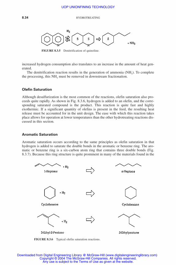
Although desulfurization is the most common of the reactions, olefin saturation also pro-ceeds quite rapidly. As shown in Fig. 8.3.6, hydrogen is added to an olefin, and the corre-sponding saturated compound is the product. This reaction is quite fast and highlyexothermic. If a significant quantity of olefins is present in the feed, the resulting heatrelease must be accounted for in the unit design. The ease with which this reaction takesplace allows for operation at lower temperatures than the other hydrotreating reactions dis-cussed in this section.
Aromatic Saturation
Aromatic saturation occurs according to the same principles as olefin saturation in thathydrogen is added to saturate the double bonds in the aromatic or benzene ring. The aro-matic or benzene ring is a six-carbon atom ring that contains three double bonds (Fig.8.3.7). Because this ring structure is quite prominent in many of the materials found in the
8.34 HYDROTREATING
FIGURE 8.3.5 Denitrification of quinoline.
FIGURE 8.3.6 Typical olefin saturation reactions.
UOP UNIONFINING TECHNOLOGY
Downloaded from Digital Engineering Library @ McGraw-Hill (www.digitalengineeringlibrary.com)Copyright © 2004 The McGraw-Hill Companies. All rights reserved.
Any use is subject to the Terms of Use as given at the website.

refinery, the symbol for this benzene ring is simplified and indicated as a hexagon with acircle inside.
Figure 8.3.8 schematically shows three typical aromatic saturation reactions. The Sinside the ring represents a six-member carbon ring that has had all the double bonds sat-urated. Because these aromatic-saturation reactions are highly exothermic, maintaining aproper temperature profile in the reactor is important. As the catalyst deactivates, the tem-peratures are raised to maintain conversion until end-of-run (EOR) conditions areapproached. In the case of aromatic saturation, EOR occurs when the equilibrium nolonger favors aromatic saturation.
Metals Removal
In addition to the previously mentioned typical hydroprocessing functions, theUnionfining unit may be designed to remove low levels of metals from the feed. The met-als to be removed include nickel and vanadium, which are native to the crude oil, as well
UOP UNIONFINING TECHNOLOGY 8.35
FIGURE 8.3.7 Benzene ring.
FIGURE 8.3.8 Typical aromatic saturation reactions.
UOP UNIONFINING TECHNOLOGY
Downloaded from Digital Engineering Library @ McGraw-Hill (www.digitalengineeringlibrary.com)Copyright © 2004 The McGraw-Hill Companies. All rights reserved.
Any use is subject to the Terms of Use as given at the website.
as silicon and lead-containing materials that are added elsewhere in the refinery. Thesemetals are poisons to downstream processing units and can pose environmental problemsif they are contained in a fuel product that will eventually combust. In the past, refinerswould operate their hydrotreating unit until the hydrotreating catalyst had no more capac-ity to absorb metals. In a hydrotreating unit, the reactor is loaded with a catalyst that isdesigned specifically to have a high capacity for metals removal if the feed metals areanticipated to be high.
CATALYST
The primary function of the catalyst used in the hydrotreating reaction is to change the rateof reactions. The suitability of a catalyst depends on a variety of factors related to the feedquality and processing objectives. The catalysts used in the UOP Unionfining processesare typically a high-surface-area base loaded with highly dispersed active metals.
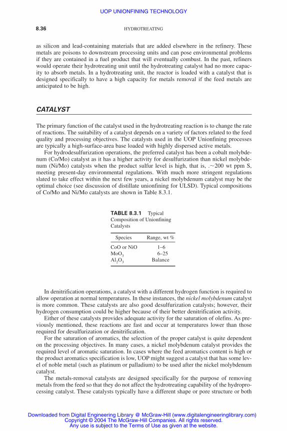
For hydrodesulfurization operations, the preferred catalyst has been a cobalt molybde-num (Co/Mo) catalyst as it has a higher activity for desulfurization than nickel molybde-num (Ni/Mo) catalysts when the product sulfur level is high, that is, .�200 wt ppm S,meeting present-day environmental regulations. With much more stringent regulationsslated to take effect within the next few years, a nickel molybdenum catalyst may be theoptimal choice (see discussion of distillate unionfining for ULSD). Typical compositionsof Co/Mo and Ni/Mo catalysts are shown in Table 8.3.1.
In denitrification operations, a catalyst with a different hydrogen function is required toallow operation at normal temperatures. In these instances, the nickel molybdenum catalystis more common. These catalysts are also good desulfurization catalysts; however, theirhydrogen consumption could be higher because of their better denitrification activity.
Either of these catalysts provides adequate activity for the saturation of olefins. As pre-viously mentioned, these reactions are fast and occur at temperatures lower than thoserequired for desulfurization or denitrification.
For the saturation of aromatics, the selection of the proper catalyst is quite dependenton the processing objectives. In many cases, a nickel molybdenum catalyst provides therequired level of aromatic saturation. In cases where the feed aromatics content is high orthe product aromatics specification is low, UOP might suggest a catalyst that has some lev-el of noble metal (such as platinum or palladium) to be used after the nickel molybdenumcatalyst.
The metals-removal catalysts are designed specifically for the purpose of removingmetals from the feed so that they do not affect the hydrotreating capability of the hydropro-cessing catalyst. These catalysts typically have a different shape or pore structure or both
8.36 HYDROTREATING
TABLE 8.3.1 TypicalComposition of UnionfiningCatalysts
Species Range, wt %
CoO or NiO 1–6MoO3 6–25Al2O3 Balance
UOP UNIONFINING TECHNOLOGY
Downloaded from Digital Engineering Library @ McGraw-Hill (www.digitalengineeringlibrary.com)Copyright © 2004 The McGraw-Hill Companies. All rights reserved.
Any use is subject to the Terms of Use as given at the website.
than the normal hydrotreating catalyst and are often designed to have some reduced levelof desulfurization or denitrification activity.
PROCESS FLOW
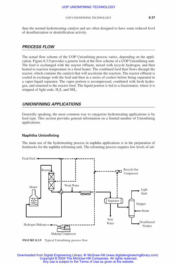
The actual flow scheme of the UOP Unionfining process varies, depending on the appli-cation. Figure 8.3.9 provides a generic look at the flow scheme of a UOP Unionfining unit.The feed is exchanged with the reactor effluent, mixed with recycle hydrogen, and thenheated to reaction temperature in a fired heater. The combined feed then flows through thereactor, which contains the catalyst that will accelerate the reaction. The reactor effluent iscooled in exchange with the feed and then in a series of coolers before being separated ina vapor-liquid separator. The vapor portion is recompressed, combined with fresh hydro-gen, and returned to the reactor feed. The liquid portion is fed to a fractionator, where it isstripped of light ends, H2S, and NH3.
UNIONFINING APPLICATIONS
Generally speaking, the most common way to categorize hydrotreating applications is byfeed type. This section provides general information on a limited number of Unionfiningapplications.
Naphtha Unionfining
The main use of the hydrotreating process in naphtha applications is in the preparation offeedstocks for the naphtha reforming unit. The reforming process requires low levels of sul-
UOP UNIONFINING TECHNOLOGY 8.37
Fresh Feed
Heater
Reactor
Wash Water
Separator
Recycle GasCompressor
LightEnds
Stripper
Steam
DesulfurizedProduct
SourWaterHydrogen Makeup
Makeup Compressor
FIGURE 8.3.9 Typical Unionfining process flow.
UOP UNIONFINING TECHNOLOGY
Downloaded from Digital Engineering Library @ McGraw-Hill (www.digitalengineeringlibrary.com)Copyright © 2004 The McGraw-Hill Companies. All rights reserved.
Any use is subject to the Terms of Use as given at the website.

fur, nitrogen, and metals in the feed. The Unionfining process reduces the sulfur and nitro-gen to less than 0.5 wt ppm and the metals to nondetectable levels. For olefinic feeds, theUnionfining process is also used to stabilize the naphtha by completely saturating the olefins.
A comparison of the typical processing conditions of the various hydroprocessing oper-ations indicates that naphtha feeds are typically the easiest to hydrotreat. Table 8.3.2 pro-vides a list of typical operating conditions for the applications discussed in this section.
Distillate Unionfining
A distillate Unionfining process is typically used to improve the quality of kerosene, jetfuel, and diesel oils. While the usual objective is to effect a desired degree of desulfuriza-tion, process conditions, and catalyst choice can be adjusted to achieve a desired improve-ment in other properties such as cetane number (smoke point for jet fuels), stability, color,odor, or aromatics content of the product.
Distillate Unionfining for ULSD (Ultralow-Sulfur Diesel)
Recent environmental regulations will require a quantum leap in the reduction of sulfur indiesel fuels. While present regulations mandate a sulfur content of 500 wt ppm (U.S.) and350 wt ppm (Europe), recently enacted legislation requires that the sulfur level be reducedto 15 wt ppm (by 2006 in the United States) and 10 wt ppm (by 2007 in Europe) beforethe end of the decade. To meet these more stringent regulations, new, more active catalystsare required as well as more severe operating conditions.
To achieve these very low levels of sulfur, the catalyst must be able to desulfurize themost difficult sulfur species—sterically hindered dibenzothiophenes. These compoundscontain alkyl groups in the 4- and 6-positions, thus greatly restricting access to the sulfuratom. An illustration of the difficulty of desulfurizing these types of compounds is givenin Fig. 8.3.10.
Since the difficult sulfur species are thiophenic, let’s consider the relative reaction ratesshown in Fig. 8.3.10, starting with thiophene which is assigned a desulfurization rate of100. As the thiophene molecule becomes more complex and bulky with the addition of anaromatic ring, as in benzothiophene, the desulfurization rate drops to 60. With the additionof another aromatic ring, dibenzothiophene, the rate of desulfurization decreases by anorder of magnitude to 5. Addition of substituents to the rings at positions far removed fromthe sulfur atom, as in 2,8-dimenthyldibenzothiophene, do not affect the rate of desulfur-ization. On the other hand, addition of substituents at positions adjacent to the sulfur atom,as in 4,6-dimenthyldibenzothiophene, greatly reduces the rate of desulfurization to a rela-tive rate of 0.5. the difficulty in desulfurizing 4,6-dimethyldibenzothiophene (and com-
8.38 HYDROTREATING
TABLE 8.3.2 Typical Hydrotreating Operating Conditions
Middle Light HeavyOperating conditions Naphtha distillate gas oil* gas oil
LHSV 1.0–5.0 1.0–4.0 0.7–1.5 0.75–2.0H2 /HC ratio, N m3/mm3 (SCF/B) 50 (300) 135 (800) 255 (1500) 337 (2000)H2 partial pressure, kg/cm2 (psia) 14 (200) 38 (400) 49 (700) 55 (800)SOR temperature, °C (°F) 290 (555) 330 (625) 355 (670) 355 (670)
Note: LHSV � liquid hourly space velocity, N � standard temperature and pressure, SCFB � stan-dard cubic feet per barrel.
*Conditions to desulfurize light gas oil to ULSD specifications (� 10 wt ppm sulfur).
UOP UNIONFINING TECHNOLOGY
Downloaded from Digital Engineering Library @ McGraw-Hill (www.digitalengineeringlibrary.com)Copyright © 2004 The McGraw-Hill Companies. All rights reserved.
Any use is subject to the Terms of Use as given at the website.
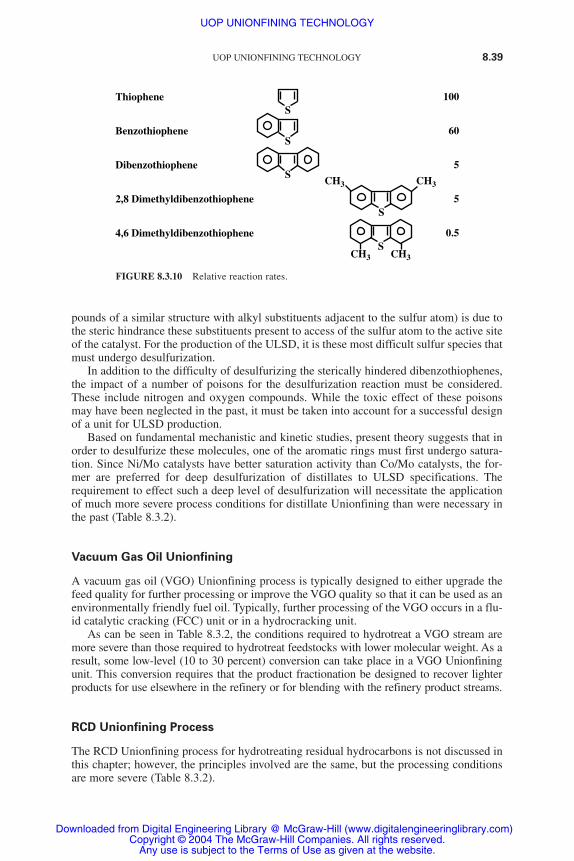
pounds of a similar structure with alkyl substituents adjacent to the sulfur atom) is due tothe steric hindrance these substituents present to access of the sulfur atom to the active siteof the catalyst. For the production of the ULSD, it is these most difficult sulfur species thatmust undergo desulfurization.
In addition to the difficulty of desulfurizing the sterically hindered dibenzothiophenes,the impact of a number of poisons for the desulfurization reaction must be considered.These include nitrogen and oxygen compounds. While the toxic effect of these poisonsmay have been neglected in the past, it must be taken into account for a successful designof a unit for ULSD production.
Based on fundamental mechanistic and kinetic studies, present theory suggests that inorder to desulfurize these molecules, one of the aromatic rings must first undergo satura-tion. Since Ni/Mo catalysts have better saturation activity than Co/Mo catalysts, the for-mer are preferred for deep desulfurization of distillates to ULSD specifications. Therequirement to effect such a deep level of desulfurization will necessitate the applicationof much more severe process conditions for distillate Unionfining than were necessary inthe past (Table 8.3.2).
Vacuum Gas Oil Unionfining
A vacuum gas oil (VGO) Unionfining process is typically designed to either upgrade thefeed quality for further processing or improve the VGO quality so that it can be used as anenvironmentally friendly fuel oil. Typically, further processing of the VGO occurs in a flu-id catalytic cracking (FCC) unit or in a hydrocracking unit.
As can be seen in Table 8.3.2, the conditions required to hydrotreat a VGO stream aremore severe than those required to hydrotreat feedstocks with lower molecular weight. As aresult, some low-level (10 to 30 percent) conversion can take place in a VGO Unionfiningunit. This conversion requires that the product fractionation be designed to recover lighterproducts for use elsewhere in the refinery or for blending with the refinery product streams.
RCD Unionfining Process
The RCD Unionfining process for hydrotreating residual hydrocarbons is not discussed inthis chapter; however, the principles involved are the same, but the processing conditionsare more severe (Table 8.3.2).
UOP UNIONFINING TECHNOLOGY 8.39
Thiophene
Benzothiophene
Dibenzothiophene
2,8 Dimethyldibenzothiophene
4,6 Dimethyldibenzothiophene
100
60
5
5
0.5
S
S
S
S
CH3
CH3 CH3
CH3
S
FIGURE 8.3.10 Relative reaction rates.
UOP UNIONFINING TECHNOLOGY
Downloaded from Digital Engineering Library @ McGraw-Hill (www.digitalengineeringlibrary.com)Copyright © 2004 The McGraw-Hill Companies. All rights reserved.
Any use is subject to the Terms of Use as given at the website.
INVESTMENT
The investment associated with the installation of a hydrotreating unit depends on the feedcharacteristics and the product specifications. Generally speaking, as the feed gets heavieror the individual product specifications are reduced, the processing requirements areincreased. These more severe processing conditions can result in more pieces of equip-ment, larger equipment, and higher operating pressure, all of which increase the cost of theunit. The required capital investment for a hydrotreating unit can vary from $500 to $2000U.S. per barrel per stream-day of capacity.
UOP HYDROPROCESSING EXPERIENCE
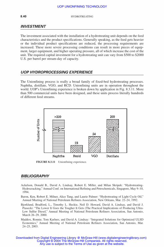
The Unionfining process is really a broad family of fixed-bed hydrotreating processes.Naphtha, distillate, VGO, and RCD. Unionfining units are in operation throughout theworld. UOP’s Unionfining experience is broken down by application in Fig. 8.3.11. Morethan 500 commercial units have been designed, and these units process literally hundredsof different feed streams.
8.40 HYDROTREATING
FIGURE 8.3.11 Unionfining experience.
BIBLIOGRAPHY
Ackelson, Donald B., David A. Lindsay, Robert E. Miller, and Milan Skripek: “Hydrotreating-Hydrocracking,” Annual Conf. on International Refining and Petrochemicals, Singapore, May 9–10,1994.
Baron, Ken, Robert E. Milner, Alice Tang, and Laurie Palmer: “Hydrotreating of Light Cycle Oil,”Annual Meeting of National Petroleum Refiners Association, New Orleans, Mar. 22–24, 1992.
Bjorklund, Bradford, L., Timothy L. Heckie, Neil D. Howard, David A. Lindsay, and David J.Piasecki: “The Lower It Goes the Tougher It Gets (The Practical Implications of Producing Ultra-Low Sulfur Diesel,” Annual Meeting of National Petroleum Refiners Association, San Antonio,March 26–29, 2000.
Maddox, Ronnie, Tom Karlnes, and David A. Lindsay: “Integrated Solutions for Optimized ULSDEconomics,” Annual Meeting of National Petroleum Refiners Association, San Antonio, Mar.24–25, 2003.
UOP UNIONFINING TECHNOLOGY
Downloaded from Digital Engineering Library @ McGraw-Hill (www.digitalengineeringlibrary.com)Copyright © 2004 The McGraw-Hill Companies. All rights reserved.
Any use is subject to the Terms of Use as given at the website.
Nguyen, Tuan A., and Milan Skripek: “Reducing Sulfur in FCC Gasoline via Hydrotreating,” AIChESpring National Meeting, Apr. 17–21, 1994.
Nguyen, Tuan, and Milan Skripek: “VGO Unionfining: Technical Case Studies,” HydrocarbonTechnology International, Sterling Publications Ltd., London, 1993.
UOP UNIONFINING TECHNOLOGY 8.41
UOP UNIONFINING TECHNOLOGY
Downloaded from Digital Engineering Library @ McGraw-Hill (www.digitalengineeringlibrary.com)Copyright © 2004 The McGraw-Hill Companies. All rights reserved.
Any use is subject to the Terms of Use as given at the website.

UOP UNIONFINING TECHNOLOGY
Downloaded from Digital Engineering Library @ McGraw-Hill (www.digitalengineeringlibrary.com)Copyright © 2004 The McGraw-Hill Companies. All rights reserved.
Any use is subject to the Terms of Use as given at the website.