005 e v29 - standard.no online/rettelser til... · imposed thermo-mechanical influence which causes...
TRANSCRIPT

EN 13445-3:2002 (E) Issue 29 (2007-10)
5
Foreword
This document (EN 13445-3:2002, EN 13445-3:2002/A4:2005, EN 13445-3:2002/A5:2006, EN 13445-3:2002/A6:2006, EN 13445-3:2002/A8:2006, EN 13445-3:2002/A11:2006, EN 13445-3:2002/A2:2007, EN 13445-3:2002/A3:2007, EN 13445-3:2002/A1:2007 and EN 13445-3:2002/A17:2007) has been prepared by Technical Committee CEN/TC 54 “Unfired pressure vessels”, the secretariat of which is held by BSI.
EN 13445-3:2002 shall be given the status of a national standard, either by publication of an identical text or by endorsement, at the latest by November 2002, and conflicting national standards shall be withdrawn at the latest by November 2002. EN 13445-3:2002/A4:2005 shall be given the status of a national standard, either by publication of an identical text or by endorsement, at the latest by January 2006, and conflicting national standards shall be withdrawn at the latest by January 2006. EN 13445-3:2002/A5:2006 and EN 13445-3:2002/A6:2006 shall be given the status of a national standard, either by publication of an identical text or by endorsement, at the latest by August 2006, and conflicting national standards shall be withdrawn at the latest by August 2006. EN 13445-3:2002/A8:2006 shall be given the status of a national standard, either by publication of an identical text or by endorsement, at the latest by October 2006, and conflicting national standards shall be withdrawn at the latest by October 2006. EN 13445-3:2002/A11:2006 shall be given the status of a national standard, either by publication of an identical text or by endorsement, at the latest by June 2007, and conflicting national standards shall be withdrawn at the latest by June 2007. EN 13445-3:2002/A2:2007 shall be given the status of a national standard, either by publication of an identical text or by endorsement, at the latest by October 2007, and conflicting national standards shall be withdrawn at the latest by October 2007. EN 13445-3:2002/A3:2007 shall be given the status of a national standard, either by publication of an identical text or by endorsement, at the latest by October 2007, and conflicting national standards shall be withdrawn at the latest by October 2007. EN 13445-3:2002/A1:2007 shall be given the status of a national standard, either by publication of an identical text or by endorsement, at the latest by December 2007, and conflicting national standards shall be withdrawn at the latest by December 2007. EN 13445-3:2002/A17:2007 shall be given the status of a national standard, either by publication of an identical text or by endorsement, at the latest by April 2008, and conflicting national standards shall be withdrawn at the latest by April 2008.
NOTE Issue 25 of EN 13445-3:2002 does not contain the specific provisions of EN 13445-3:2002/A2:2007 concerning non-destructive testing of welded joints and final assessment for vessels designed by experimental methods, which are incorporated in issue 25 of EN 13445-5:2002.
Attention is drawn to the possibility that some of the elements of this document may be the subject of patent rights. CEN [and/or CENELEC] shall not be held responsible for identifying any or all such patent rights.
This document has been prepared under a mandate given to CEN by the European Commission and the European Free Trade Association, and supports essential requirements of EU Directive 97/23/EC.
For relationship with EU Directive(s), see informative Annex ZA, which is an integral part of this document.
In this standard the Annexes A, B, C, E, F, G, J, P and Q are normative and the Annexes D, H, I, K, L, M, N, O, R and S are informative.
This European Standard consists of the following Parts:
― Part 1: General. ― Part 2: Materials. ― Part 3: Design. ― Part 4: Fabrication. ― Part 5: Inspection and Testing. ― Part 6: Requirements for the design and fabrication of pressure vessels and pressure parts constructed from spheroidal graphite cast iron. CR 13445-7, Unfired pressure vessels - Part 7: Guidance on the use of conformity assessment procedures.
According to the CEN/CENELEC Internal Regulations, the national standards organizations of the following countries are bound to implement this European Standard: Austria, Belgium, Bulgaria, Cyprus, Czech Republic, Denmark, Estonia, Finland, France, Germany, Greece, Hungary, Iceland, Ireland, Italy, Latvia, Lithuania, Luxembourg, Malta, Netherlands, Norway, Poland, Portugal, Romania, Slovakia, Slovenia, Spain, Sweden, Switzerland and United Kingdom.
EN 13445-3:2002 (E) Issue 27 (2007-06)
6
1 Scope
This Part of this European Standard specifies requirements for the design of unfired pressure vessels covered by EN 13445-1:2002 and constructed of steels in accordance with EN 13445-2:2002.
EN 13445-5:2002, Annex C specifies requirements for the design of access and inspection openings, closing mechanisms and special locking elements.
NOTE This Part applies to design of vessels before putting into service. It may be used for in service calculation or analysis subject to appropriate adjustment.
2 Normative references
This European Standard incorporates by dated or undated reference, provisions from other publications. These normative references are cited at the appropriate places in the text and the publications are listed hereafter. For dated references, subsequent amendments to or revisions of any of these publications apply to this European Standard only when incorporated in it by amendment or revision. For undated references, the latest edition of the publication referred to applies (including amendments).
EN 286-2:1992, Simple unfired pressure vessels designed to contain air or nitrogen — Part 2: Pressure vessels for air braking and auxiliary systems for motor vehicles and their trailers.
EN 288-8:1995, Specification and approval of welding procedures for metallic materials — Part 8: Approval by a pre-production welding test.
EN 764-1:2004, Pressure equipment — Terminology — Part 1: Pressure, temperature, volume, nominal size
EN 764-2:2002, Pressure equipment — Part 2: Quantities, symbols and units
EN 764-3:2002, Pressure equipment — Part 3: Definition of parties involved
EN 837-1, Pressure gauges – Part 1: Bourdon tube pressure gauges - Dimensions, metrology, requirements and testing
EN 837-3, Pressure gauges –Part 3: Diaphragm and capsule pressure gauges - Dimensions, metrology, requirements and testing
EN 1092, Flanges and their joints. Circular flanges for pipes, valves, fittings and accessories, PN-designated.
EN 1591-1:2001, Flanges and their joints - Design rules for gasketed circular flange connections – Calculation method.
EN 1708-1:1999, Welding - Basic weld joint details in steel – Part 1: Pressurized components
EN 10222-1:1998, Steel forgings for pressure purposes — Part 1: General requirements for open die forgings
EN ISO 4014:2000, Hexagon head bolts — Product grades A and B (ISO 4014:1999).
EN ISO 4016:2000, Hexagon head bolts — Product grade C (ISO 4016:1999).
ISO 261:1998, ISO general purpose metric screw threads — General plan.
3 Terms and definitions
For the purposes of this Part of this European Standard, the terms and definitions given in EN 13445-1:2002, EN 13445-2:2002 and the following apply:
3.1 action imposed thermo-mechanical influence which causes stress and/or strain in a structure, e.g. an imposed pressure, force, temperature
3.2 analysis thickness effective thickness available to resist the loadings in corroded condition
EN 13445-3:2002 (E)Issue 1 (2002-05)
641
PPTT
dd CCdd CC
PPTT
dd 11
dd SS
PSS
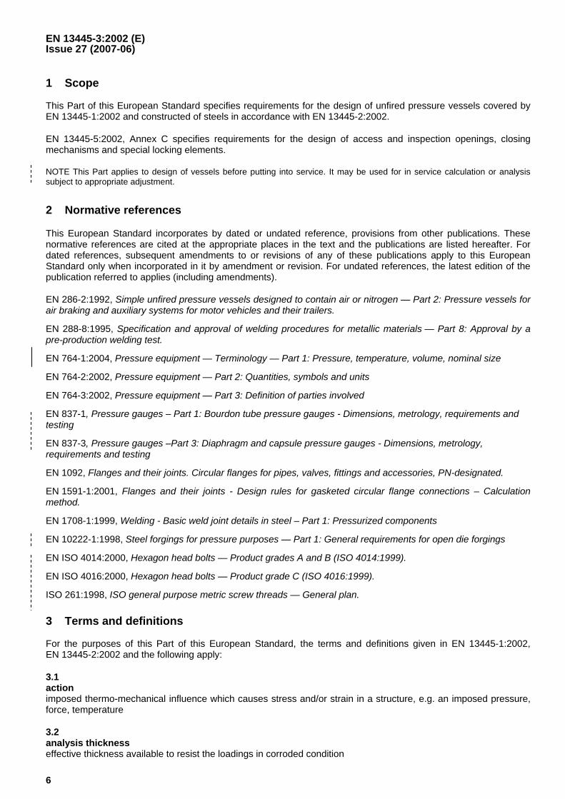
Figure J-6 • Fixed tubesheets without expansion bellows
J.3.2 Subscripts
NOTE Large latin letters reffer to components or regions of components or kinds of values.Small latin letters specify properties or kinds of loadings or kinds of reactions.
A for Outer zone of the tubed region {C: German: "Außenbereich"};
B for Bolts; orBaffle;
C for Channel;
D for Difference of values;
E for Effective values;
F for Flange;
G for Gasket;
I for Inner zone of the tubed region {C: German: "Innenbereich"};
J for Expansion bellows {C: Clause 13};
K for Compensation {C: German: "Kompensation"};
M for Moment related values;
P for Plate (tubesheet); orPressure related values;
Q for General load related values {C: Similar to "P" and "R"};
R for Resultant load; orTubebundle {C: German: "Rohrbündel"}, tubed region ; orany value between "Q" and "S";
S for Shell;
EN 13445-3:2002 (E) Issue 29 (2007-10)
642
T for Tubes or tube side (channel side);
U for Untubed region;
W for Weight; or Weld;
X for Tube-tubesheet-connection;
av for average value;
b for bending;
c for compressive (stress or force);
e for external (pressure); or effective;
i for internal (pressure);
l for longitudinal;
min for minimum value;
max for maximum value;
opt for optimum value;
red for reduced value;
t for tensile (stress or force); or total, true.
J.3.3 Symbols
NOTE Units are given in square brackets; [1] indicates a "dimensionless" quantity;
AR is the cross-sectional area of the tubed region, [mm2];
AR(min) is the minimum area of the tubed region, [mm2], see J.5.1.1.3.2;
AX is the cross-sectional area of the connection between tube and tubesheet, [mm2];
aT is the effective throat thickness of the tube end weld [mm], specified as follows: aT,P at the plate (tubesheet); aT,T at the tube; aT,R between plate and tube;
B0 is the determinant of all compliances [1];
BR1, BR2, BR3 are the compliances for the tubebundle [1];
BS1, BS2, BS3 are the compliances for shell and channel [1];
bF is the true width of a flange like part of the tubesheet [mm], see Figures J-10 to J-13;
bR is the average width of the untubed rim subject to pressure on both sides [mm], see J.5.1;
bS is the true width of the untubed rim subject to pressure on one side only [mm], may be positive or negative; see J.5.1;
bU is the maximum width of the untubed rim [mm], obtained from the tubesheet layout; see Figure J-7 and J.9.3;
C0, CA, CC, CAA, CAC, CCC are coefficients [1] to determine the buckling length, see J.7.1.3;
C1, C2 are factors for the fatigue design [1], see Figure J-15;

EN 13445-3:2002 (E) Issue 29 (2007-10)
643
DJ is the inside diameter of the expansion bellows [mm]; see sublause 13.5;
dC, dS are the inside diameters of the channel (C), of the shell (S), [mm];
d0, d0,e is the tubehole diameter [mm], d0 is the real value, d0,e is the effective value;
d1 is the average outside diameter of the tubed region [mm], see J.5.1;
d1(av) is the average of ( )min1d and ( )max1d , [mm], see J.5.1.1.4;
d1(max) is the maximum value of 1d , [mm], see J.5.1.1.2;
d1(min) is the minimum value of 1d , [mm], see J.5.1.1.3;
d2 is the true outside diameter [mm] over which PS and PT act;
d3, d3,e is the bolt pitch circle diameter [mm]; d3 for the real value, d3,e for the effective value;
dGC, dGS are the effective gasket diameters [mm] for channel side (C), shell side (S);
dK is the diameter for compensation of axial forces [mm]; for floating heads this is the diameter of the sliding face at a packed gland or an O-ring seal; for expansion bellows this is the mean inside diameter of the bellows: dK = DJ + hJ ;
dT is the tube outside diameter [mm];
EP, ET are the elastic moduli of the tubesheet (P = plate), of the tubes (T), [MPa];
EC, ES are the elastic moduli of the channel (C), of the shell (S), [MPa];
E* is the effective elastic modulus of the tubesheet [MPa], see Figures 13.7.6-1, 13.7.6-2;
eC is the analysis thicknesses of the channel adjacent to the tubesheet [mm];
eF is the average thickness of a flange like part of the tubesheet [mm], see Figures J-10 to J-13;
eP is the analysis thickness of the tubesheet (plate) [mm] in the tubed region and the untubed rim;
eP,red is a possibly reduced thickness of the tubesheet (plate) at its outer periphery [mm]; eP,red ≤ eP ;
eS is the analysis thicknesses of the shell adjacent to the tubesheet [mm];
eS,av is the average thicknesses of the shell over the total length LT [mm];
eT is the tube thickness [mm];
eU is the analysis thickness of the tubesheet in its greatest ubtubed region [mm]; normally eU = eP ;
FB is the total force applied by the bolts (total force for one flange connection) [N], see Annex G;
FG,C, FG,S are the total gasket reaction forces [N], channel side (C), shell side (S);
[Ft], [Fc] are the allowable total axial forces in the shell [N], [Ft] for tension, [Fc] for compression, see J.7.5;
FR is the total axial force acting on tubebundle and shell [N], see J.7.5;
FW is the total weight acting as a force on a tubesheet [N], see J.9.4;
fC is the nominal design stress for the channel adjacent to the tubesheet [MPa];
fF is the nominal design stress for the flange like part of tubesheet (plate) [MPa]; normally fF = fP ;
fP is the nominal design stress for the tubesheet (plate) [MPa];
fS is the nominal design stress for the shell adjacent to the tubesheet [MPa];
fT is the nominal design stress for the tubes [MPa];
fT,t is the allowable longitudinal stress for the tubes in tension [MPa]; see J.7.3;

EN 13445-3:2002 (E) Issue 29 (2007-10)
644
fT,c is the allowable longitudinal stress for tubes in compression [MPa]; see J.7.3;
fX is the calculated design stress for the tube-to-tubesheet connection [MPa]; see J.7.3; fX,E and fX,W are special values of fX ;
H1, H2, H3 are factors (compliances) used in the fatigue design [1], see Figure J-15;
hJ is the inside height of the expansion bellows [mm]; see sublause 13.5;
j is an integer to identify any trapezoidal area (tubed or untubed);
k is an integer to identify an untubed (pass partition) zone;
Ke1, Ke2, Ke3 are effective stress-strain concentration factors [1] used in the fatigue design, see J.10;
L1 , L2 , L3 are loading parameters [1], used in the calculation of a load ratio, see J.9.1;
LT is the true total length of the tubes [mm]; in Figure J-9 shown between outer faces of tubesheets;
lA is the length of tubes [mm] between the first tubesheet and the first supporting baffle, see Figure J-9;
lB is the length of tubes [mm] between two adjacent supporting baffles, see Figure J-9. If along one tube more than one lB exist, all lB are presupposed to be equal;
lC is the length of tubes [mm] between the last supporting baffle and the second tubesheet, see Figure J-9;
lR is a characterisitc length of the tubebundle [mm], used for fatigue design, see J.10.3;
lT,K is the buckling length of tubes [mm], see J.7.1;
lX is the length of the strength attachement between tube and tubesheet [mm], see J.5.2.1;
M1 is the resultant bending moment [Nmm/mm] at the diameter d1 ;
M2 is the resultant bending moment [Nmm/mm] at the diameter d2 ;
MA is the active bolt load bending moment [Nmm/mm] at the diameter d2 , see J.8.1;
MB is the active fluid pressure bending moment [Nmm/mm] at the diameter d2 , see J.8.2;
MC is the reactive bending moment [Nmm/mm] from connected components, see J.8.3;
MD is the reactive bending moment [Nmm/mm] limitation at the diameter d2 , see J 8.4;
NB is the number of baffles [1]; NB,t is the true total number, NB,e is the effective number;
NC is the number of load cycles [1];.
NI Number of ideal possible, not real existing tubes (general) [1]; see J.5.1;
NI(min) is the total minimum number of potential extra tubes for the whole tubed area, [1], see J.5.1.1.3.2;
NI(k) is the number of potential extra tubes in a given untubed trapezoidal area, [1], see J.5.1.1.3.2;
NI(r) is the number of potential extra tubes in a given row, [1], see J.5.1.1.3.2;
NT is the number of real existing tubes [1]; in a U-tube type the number of tubeholes [1];
nB is the number of bolts [1] in a flange connection;
PA, PI are the resultants of active and reactive axial forces per area unit in the tubebundle in the tubed region [N/mm2 = MPa] ; PA in the outer zone, PI in the inner zone; see J.7.6;
PD is the direct difference between tube side and shell side fluid pressure [MPa], see J.6.2, J.7.2;
EN 13445-3:2002 (E) Issue 29 (2007-10)
645
PE is the effective difference pressure in the tubed region [MPa], see J.7.2;
PM is a "pressure" [MPa], representing the resultant bending moment M1 (resultant of active and reactive moments, may be zero) at the outer boundary of the tubed region, see J.8.6;
PQ is a "pressure" [MPa], representing the resultant effective axial force (resultant of active and reactive forces, may be zero) at the outer boundary of the tubed region [MPa], see J.6.3, J.7.6;
PR is a "pressure" [MPa], representing the resultant active axial shear force at the outer boundary of the tubed region [MPa], see J.6.2, J.7.5;
p is the tube pitch in the tubed region [mm], see Figure J-7;
pb is the tube pitch in relation to the height of the trapezoidal area, [mm];
pc is the tube pitch in relation to the width of the trapezoidal area, [mm];
QA, QI are reactive axial forces per area unit of the tubebundle in the tubed region [N/mm2 = MPa]; QA in the outer zone, QI in the inner zone; see J.7.4;
[Qt], [Qc] are the allowable axial forces per area unit of the tubebundle in the tubed region [N/mm2]; [Qt] for tensiom, [Qc] for compression; see J.7.3;
q is a parameter for the tube support [1], see J.9.3;
r is an integer to identify a tube row;
ro is the radius of the outermost tube hole centre [mm]; see Figure J-7(a) and NOTE in J.5.1.1.2 (also Figure 13.7-1);
tS, tT are temperature ranges [K] between maximum and minimum temperature for shell (S), tubes (T). For their calculation, the assembly temperature shall be assumed to be +20oC;
u, v, w are auxiliary values [1], used in J.7.6;
xS, xT are relative areas of the tubesheet [1] subject to PS and PT respectively; see J.7.1;
Y is an auxiliary value [1], used in J.7.1;
αS, αT are the thermal expansion coefficients of shell, the tubes [K-1];
β is an auxiliary parameter given by equation (J.10.2-3);
γR is the rigidity factor for the untubed rim, see J.10.3;
Δd(act) is the actual difference between ( )max1d and ( )min1d , [mm];
Δd(all) is the allowable difference between ( )max1d and ( )min1d , [mm];
ΔM1, ΔM2 are ranges of bending moments in the tubesheet [Nmm/mm], used for fatigue check;
ΔPF, ΔPS, ΔPT are ranges of pressures [MPa], used for a fatigue check, see J.10.2;
ΔS1, ΔS2 are ranges of shear forces in the tubesheet [N/mm], used for fatigue check, see J.10.3;
Δσb1, Δσb2 are ranges of calculated bending stresses in the tubesheet [Nmm2], used for fatigue check, see J.10.3;
ΔσlT is the range of calculated longitudinal stress in the tubes [Nmm2], used for fatigue check;
ΔσR is the allowable stress range in the tubesheet (plate) [Nmm2], used for fatigue check;
δX is a factor for tube to tubesheet relative strength [1], see J.5.2;
ζ is the force distribution parameter [1] for supported tubesheets; this is the relative radius of the boundary between the reactions QI and QA, see J.7.1.1 and J.7.6.2;
η is the moment distribution parameter [1] for all tubesheets; this is the relative radius of the boundary between constant and variable tangential bending moment in the tubesheet, see J.6.3, J.7.1.1 and J.7.6.3;
ϑ is the relative cross-sectional area of the tubes [1]; see J.7.1;

EN 13445-3:2002 (E)Issue 1 (2002-05)
646
�P is the relative shear strength of the tubesheet [1], see J.5.2;
�A , �C are geometric parameters for tube buckling [1], see J.7.1;
�R , �S are geometric parameters for untubed rims [1], see J.5.1;
�X is the coefficient of friction [1] for the tube-to-tubesheet connection by expansion, see J.7.3;
�* is the tubesheet ligament efficiency in bending (clause 13); it is in this annex replaced by �P ;
�P is the Poissons ratio for the undrilled tubesheet (plate) [1];
�S is the Poissons ratio for the shell [1];
�T is the Poissons ratio for the tubes [1];
�* is the effective Poissons ratio for the drilled tubesheet [1], obtained from subclause 13.7;
� is an active stress general [Nmm2], to be specified by subscripts, see J.7.3, �T(P) ;
[�] is an allowable stress general [Nmm2], to be specified by subscripts, see J.7.5;
�T(P) is an average longitudinal stress in the tubes [MPa], divided by safety factor 1,50, see J.7.3;
�B , �S , �U , �W and �P,t are load ratios [1], see J.2.2 and J.9;
�P is the relative bending strength of the tubesheet [1], see J.5.2;
� is a parameter for the untubed region at the boundary [1], see J.9.3;.
E is the stiffness parameter for the tubed region [1], see J.10.3;
R is the rigity factor for the tubed region [1], see J.10.3.
J.4 General
J.4.1 Conditions of applicability
J.4.1.1 Geometry and materials
The method applies for tubebundles (and some connected components) under the following conditions:
- The whole tubebundle (as the main component of a tubesheet heat exchanger) is axisymmetric.Permitted deviations from the axisymmetry are defined and limited below.
- Each tubesheet (also called "plate", subscript P) has only one central tubed region (nearly circular).Within the tubed region there are permitted small untubed areas, e.g. for pass partitions and tie-rods.The outer boundary of the tubed region needs not to be exact circular, but shall it be approximately.
- The tubesheet thickness eP and the pitch p are the same (constant) for the whole tubed region.For a second tubesheet within the tubebundle the thickness may be different, but again constant.
- Outside the tubed region the plate has an untubed region, beeing not too large.Their outside boundary shall be exact circular, as all other components outside also (with the onlysmall deviations due to the finite number of flange bolts).
- All (inner) tubes have the same cross section dT• eT and are from the same material.
- For tubebundles with two tubesheets all tubes have the same straight lengt LT ; no tie rod is connectedto both tubesheets. (For a tubebundle with only one tubesheet the lengths of the curved tubes may bearbitrary different. If a tubebundle with two tubesheets has curved tubes, it shall be calculated as anU-tube type, where each tubesheet is to be calculated separate.)

EN 13445-3:2002 (E)Issue 1 (2002-05)
649
J.4.3.2 Load cases to be calculated
J.4.3.2.1 Load limit calculations (J.5 to J.9) shall be provided
- for all types of tubebundles
- using all real possible combinations of design pressures and additional design loads.
NOTE 1 A restriction to one calculation for the absolute maximum �PT - PS� in general is not sufficient.
NOTE 2 Observe the real possible design loads (not normal acting operating loads) are to be used.
J.4.3.2.2 Fatigue asessment (J.10) shall be provided
- for fixed tubesheets without expansion bellows only
- using all normal simultaneously acting operating pressures, additional loads and temperatures .
NOTE 3 In many cases it is sufficient to calculate for the worst load change only, which is given by the highestvalue ��PF� from eqation (J.10.2-2). But in other cases with different comparable load changes, especially ifslightely higher load values are connected with only slightely lower numbers of load cycles, it may be necessaryto calculate several times and to check the acceptance by subclause 17.7.
NOTE 4 Observe the normal acting operating loads (not real possible design loads) are to be used.
J.4.3.3 Working with the method
J.4.3.3.1 Basic rules
The calculation shall be made in the corroded condition. Several iterations may be required.
Where the two tubesheets in a tubebundle differ in dimension, material or edge support condition,separate calculations shall be made for each tubesheet.
The calculation starts with J.5.1. At least in J.5.2 a value shall be assumed for the tubesheet thicknesseP. Then - depending on the heat exchanger type - either subclause J.6 or subclause J.7 is to be used.Clauses J.8 and J.9 always are to be applied.
NOTE Many calculations within J.5 to J.7 are independent of eP ; however it is to be observed, that lX and eF may tobe changed if eP is changed; also fP and FB may depend on eP. Therefore, to be safe, it is recommended after eachchange of eP to repeat the calculations starting from J.5.2.
J.4.3.3.2 Main conclusions
If the calculated total load ratio �P,t is less than 1,0, the result is acceptable; but the real requiredtubesheet thickness may be less than the assumed and the calculation should be repeated using asmaller eP.
If the calculated total load ratio �P,t is greater than 1,0, the result is not acceptable, the assumedtubesheet thickness eP must be increased and the calculation is to be repeated.
J.4.3.3.3 Additional rules
If for tubebundles with fixed tubesheets without expansion bellows the fatigue criteria are govern, thedesign shall be based on subclause J.10 Fatigue asessment. In these cases not only a greater tubesheetthickness may lead to acceptable results, e.g. a less stiff design in some cases also may be a sufficientbetter design.

EN 13445-3:2002 (E) Issue 29 (2007-10)
J.5 Parameters for all types
J.5.1 Diameters and widths
J.5.1.1 Outside diameter d1 of tubed region
J.5.1.1.1 General
The procedure for calculating 1d is given below.
NOTE Upper and lower limits for 1d can be established by considering the space within the tubed area which is available
for additional tubes. 1d is calculated from the limits.
J.5.1.1.2 Maximum diameter ( )max1d
Determine ( )max1d as follows:
( ) To drd += 2max1 (J.5.1-1)
NOTE If an isolated tube or small group of tubes lies outside the main tubed region (by a distance of more than one pitch) it should be ignored when determining or and dT.
J.5.1.1.3 Minimum diameter ( )min1d
J.5.1.1.3.1 Defining trapezoidal areas
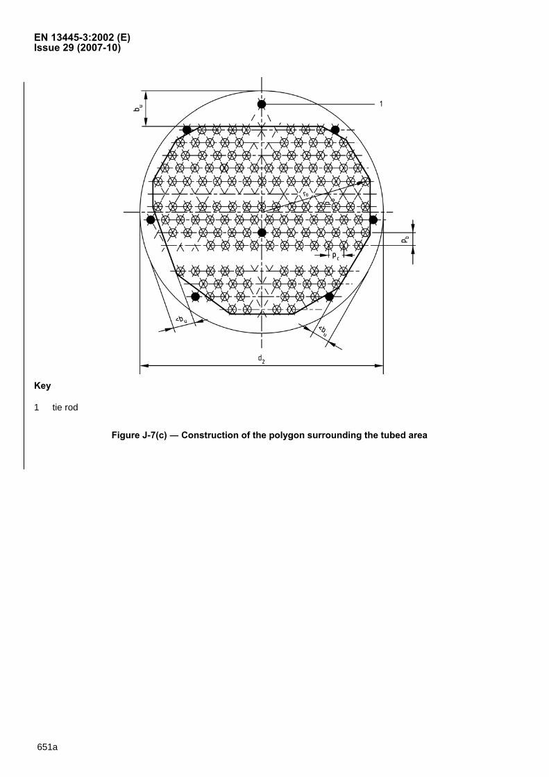
Draw the tangent lines to the outside tubes to enclose the tubed region within a polygon. The positions of the tie rods shall be ignored.
NOTE 1 An example is shown in Figures J-7(c) and J-7(d).
NOTE 2 For simplicity, where two tangent lines have nearly equal slopes, they can be replaced by a single tangent line if this line lies outside the centres of any tubes it crosses (i.e. it cuts less than half tube sections). (See area of height 7b in Figure J-7(b).)
Divide the tubed region into (perforated or un-perforated) trapezoidal areas by drawing straight lines parallel to the tube rows.
Where the intersection of the tangent lines which form the polygon lies closer to the tube centreline, the construction line shall be through the tube centres (see Figure J-7(d)). Where the intersection of the tangent lines which form the polygon lies closer to the tangent line than to the tube centreline, the construction line shall be the tangent to the tube row (see Figure J-7(b)). This also applies when the intersection is mid-way between the tube centre line and the tube tangent line. Extend the construction lines to the enclosing polygon to form trapezoidal areas. Denote the heights of the trapezoidal areas by jb (j = 1,2, ..,) and widths by jc (j = 0, 1, 2, .,).
J.5.1.1.3.2 Determination of ( )minRA
Determine ( )minRA by one of the following three methods.
(a) Tube counting
Determine the total number of potential extra tubes ( )minIN as follows.
Calculate the tube pitches bp and cp as follows:
650
EN 13445-3:2002 (E) Issue 29 (2007-10)
On triangular pitch:
ppb 0,866= (J.5.1-2)
and
ppc = (J.5.1-3)
On square pitch:
ppb = (J.5.1-4)
and
ppc = (J.5.1-5)
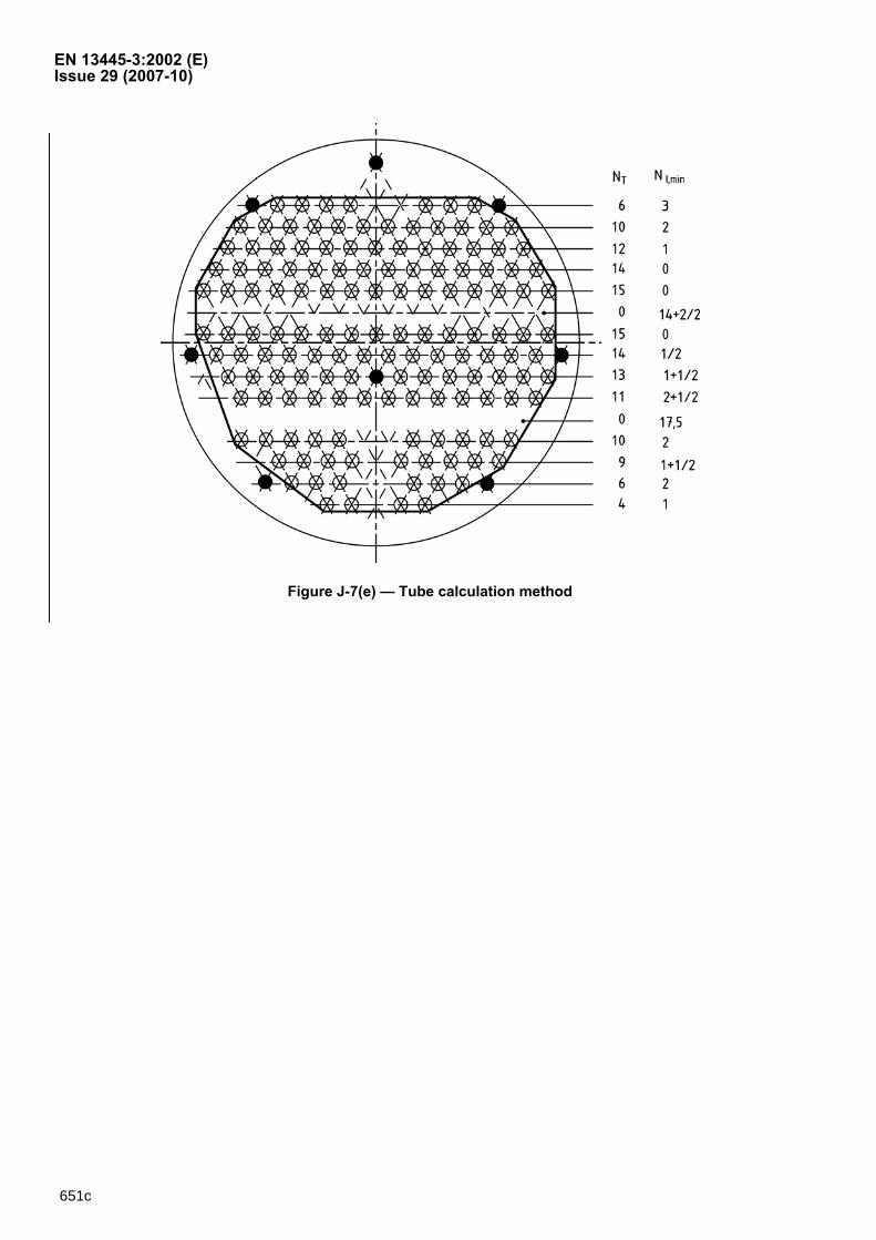
For each tube row, count all unfilled positions within the row. For unfilled positions at the ends of the row, multiples of half a tube may be added when the tangent line lies inside the centre of the potential extra tube. This gives
( )rIN for each row.
NOTE An example of this is shown in Figure J-7(e).
For a pass partition zone where the distance between the adjacent tube rows equals an integral number of tube pitches, count all the potential extra tube positions to obtain )(kIN for that zone.
NOTE Area of height 3b in Figure J-7(d) is one where the distance between the adjacent tube rows equals an integral number of tube pitches.
For a pass partition zone or other untubed area, with arbitrary distances to the adjacent tube rows, calculate )(kIN for that zone as follows:
( )[ ]( )
cb
pkpkbpkkI pp
ccpbN
⋅
++= −
2,,1, (J.5.1-6)
In Equation J.5.1-6, pbk , is the distance between the centrelines of adjacent tube rows and bp is the corresponding (vertical) pitch; pck ,1− and pck , are the (upper and lower) widths of the trapezoidal area respectively; and cp is the corresponding (horizontal) pitch, see Figure J-7(d). The calculated number ( )kIN for each partition zone of this type shall be rounded up to the nearest half tube.
NOTE The area of height pb ,5 in Figure J-7(b) is an untubed area with an arbitrary distance between the adjacent tube rows.
( )minIN is the sum of all the potential extra tubes from the rows, ( )rIN , and all the potential extra tubes from the
pass partition zones, ( )kIN . In extreme cases (where the layout is fully packed) ( )minIN may equal zero.
Calculate area ( )minRA as follows:
( )( ) cbITR ppNNA ⋅⋅+= min(min) (J.5.1-7)
(b) Calculation of all the trapezoidal areas
650a

EN 13445-3:2002 (E) Issue 29 (2007-10) Calculate the values of Jb and Jc for each of the trapezoidal areas (see FigureJ-7(d)) as follows:
⎯ in the perforated zones, the heights Jb are to be calculated as the nearest multiple of bp and 2Td .
The widths Jc are similarly to be calculated as the nearest multiple of cp and 2Td . In case of doubt,
always assume the smaller value.
⎯ for any pass partition zones, the height of the zone, whether or not it is an exact multiple of bp , is inserted in Equation J.5.1-8.
Calculate ( )minRA to include all perforated and un-perforated areas as follows:
( ) ( ) ( ){ } ( )∑=
=− ⋅+⋅=⋅++⋅++⋅+⋅=
max
11332221110(min) 5,0.....5,0
jj
jjjjR bccbccbccbccA (J.5.1-8)
(c) Measurement of area
Measure area ( )minRA
NOTE This could be done by computer or other device.
J.5.1.1.3.3 Calculation of ( )min1d
Calculate ( )min1d from ( )minRA as follows:
( ) π(min)
min14 RA
d = (J.5.1-9)
NOTE If ( )min1d exceeds ( )max1d , the calculation is incorrect and should be checked.
J.5.1.1.4 Average diameter ( )avd1
Calculate ( )avd1 as follows:
( )( ) ( )[ ]
2max1min1
1dd
d av+
= (J.5.1-10)
J.5.1.1.5 Calculation of outside diameter d1
Compare the calculated diameter difference and the allowable diameter tolerance as follows:
( ) ( ) ( )min1max1 ddd act −=Δ (J.5.1-11)
( ) ( ){ }avall dpd 103,0;0,1min=Δ (J.5.1-12)
If the following condition is met:
( ) ( )allact dd ΔΔ ≤ (J.5.1-13)
In all following calculations, put
( )avdd 11 = (J.5.1-14)
650b
EN 13445-3:2002 (E) Issue 29 (2007-10)
If the condition Equation (J.5.1-13) is not met, calculate M as follows:
( )( )
1+⎟⎟⎠
⎞⎜⎜⎝
⎛=
all
act
dd
IntegerMΔΔ
(J.5.1-15)
where
( )( ) ⎟
⎟⎠
⎞⎜⎜⎝
⎛
all
actdd
IntegerΔΔ
is the integer below or equal to the value of ( )( ) ⎟
⎟⎠
⎞⎜⎜⎝
⎛
all
act
ddΔΔ
.
Make all subsequent calculations M times with values of 1d given by:
( )( ) ( )( )( )1
min1max1min11 −
−+=
Mdd
ndd (J.5.1-16)
where n = 0,1,2..M -1
The result with the greatest load ratio, and hence the greatest required tube plate thickness, shall be taken as the required tube sheet thickness.
NOTE The repeated calculations are necessary to minimize the error from calculations for which assume symmetry on components which are non-axisymmetric.
650c


EN 13445-3:2002 (E) Issue 29 (2007-10)
NTT NNI,min NNI,max
7 0 0
6 0 1
5 0 1
4 0 1
0 0 3
6 0 1
5 0 1
4 0 1
2 1 1
39 1 10
NTT NNI,min NNI,max
0 0 4
6 0 0
6 0 1
0 6 7
6 0 1
6 0 0
4 0 0
28 6 13dd11
dd11
pp
pp
dd22
bb UUbb UU
dd22
Figure J-7(b) ― Tubesheet drilling, square pattern; examples for NT, NI, d1 and bU
Figure J-7(a) ― Tubesheet drilling, triangular pattern; examples for NT, NI, d1 and bU
651
EN 13445-3:2002 (E) Issue 29 (2007-10)
Key
1 tie rod
Figure J-7(c) ― Construction of the polygon surrounding the tubed area
651a

EN 13445-3:2002 (E) Issue 29 (2007-10)
Key
1 pass partition with a height which equals multiple tube pitches
2 pass partition with an arbitary height
Note The equations to calculate the dimensions in Figure J-7(d) are:
Area 1 2
80T
cdpc += ; bpb =1
Area 2 2
111T
cdpc += ;
232
Tb
dpb +=
Area 3 ⎟⎠⎞
⎜⎝⎛+=
22142
Tc
dpc ; bpb 23 =
Area 4 ⎟⎠⎞
⎜⎝⎛+=
22143
Tc
dpc ; bpb 24 =
Area 5 ⎟⎠⎞
⎜⎝⎛+=
22134
Tc
dpc ; pb bpb ,55 +=
Area 6 ⎟⎠⎞
⎜⎝⎛+=
22115
Tc
dpc ; 26T
bdpb +=
Area 7 ⎟⎠⎞
⎜⎝⎛+=
2296
Tc
dpc ; bpb 27 = ;
2
47T
cdpc +=
Figure J-7(d) — Construction of trapezoidal areas
651b
EN 13445-3:2002 (E) Issue 29 (2007-10)
Figure J-7(e) — Tube calculation method
651c

EN 13445-3:2002 (E) Issue 29 (2007-10)
653
J.5.1.2 Other diameters, widths and parameters
The outside diameter of the tubesheet region subject to fluid pressure on both sides shall be calculated from
d2 = min{ max(dC , dGC ); max(dS , dGS )} (J.5.1-17)
Then the following shall be calculated:
bR = (d2 - d1 )/2 (J.5.1-18)
λR = 2·bR/d1 (J.5.1-19)
bS = { max(dC ; dGC ) - max(dS ; dGS ) }/2 (J.5.1-20)
λS = 2·bS/d2 (J.5.1-21)
NOTE: bS and λS may be positive or negative as well and the sign must be strictly observed.
J.5.2 Tubesheet perforation
J.5.2.1 Effective tube holes
The effective diameter of the tube holes shall be determined from:
d0,e = max{ d0 - 2·δX·AX/eP ; dT - 2·eT } (J.5.2-1)
in which:
δX = min{ 1,0 ; fT/fP } (J.5.2-2)
TTTXX )··( eedlA += (J.5.2-3)
For welded tube-tubesheet-connections the length lX is the weld height hT at the tube; for expanded tubes it is the expanded length lX ; both are shown in Figure J-8.
NOTE: Eq.(J.5.3-1) can be evaluated only if eP is known; therefore first eP must be assumed.
J.5.2.2 Parameters of equivalent weakened plate
The relative bending strength and the relative shear strength κP are to be calculated thus:
ϕP = 1 - d0,e/p (J.5.2-4)
For ϕP < 0,50:
)1( PPP ϕϕκ −⋅= (J.5.2-5)
For ϕP ≥ 0,50:
κP = 0,50 (J.5.2-6)
J.6 Tubesheets unsupported by tubes
J.6.1 General
NOTE 1 Heat exchangers in which the tubesheet derives no support from the tubes are as follows: U-tube type (Figure J-1); exchangers with capped tubes and a single tubesheet, e.g. electric heaters; exchangers with general curved tubes and one, two or more tubesheets.
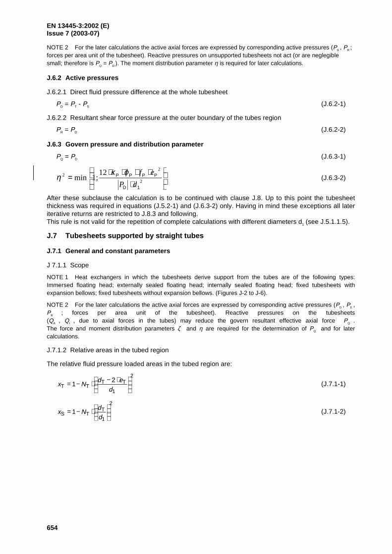
EN 13445-3:2002 (E)Issue 7 (2003-07)
654
NOTE 2 For the later calculations the active axial forces are expressed by corresponding active pressures (PD , PR ;forces per area unit of the tubesheet). Reactive pressures on unsupported tubesheets not act (or are neglegiblesmall; therefore is PQ = PD ). The moment distribution parameter η is required for later calculations.
J.6.2 Active pressures
J.6.2.1 Direct fluid pressure difference at the whole tubesheet
PD = PT - PS (J.6.2-1)
J.6.2.2 Resultant shear force pressure at the outer boundary of the tubes region
PR = PD (J.6.2-2)
J.6.3 Govern pressure and distribution parameter
PQ = PD (J.6.3-1)
⋅⋅⋅⋅⋅
=2
22 12
;1min1D
PPPP
dP
efϕκη (J.6.3-2)
After these subclause the calculation is to be continued with clause J.8. Up to this point the tubesheetthickness was required in equations (J.5.2-1) and (J.6.3-2) only. Having in mind these exceptions all lateriterative returns are restricted to J.8.3 and following.This rule is not valid for the repetition of complete calculations with different diameters d1 (see J.5.1.1.5).
J.7 Tubesheets supported by straight tubes
J.7.1 General and constant parameters
J 7.1.1 Scope
NOTE 1 Heat exchangers in which the tubesheets derive support from the tubes are of the following types:Immersed floating head; externally sealed floating head; internally sealed floating head; fixed tubesheets withexpansion bellows; fixed tubesheets without expansion bellows. (Figures J-2 to J-6).
NOTE 2 For the later calculations the active axial forces are expressed by corresponding active pressures (PD , PE ,PR ; forces per area unit of the tubesheet). Reactive pressures on the tubesheets(QA , Q
I , due to axial forces in the tubes) may reduce the govern resultant effective axial force PQ .
The force and moment distribution parameters ζ and η are required for the determination of PQ and for latercalculations.
J.7.1.2 Relative areas in the tubed region
The relative fluid pressure loaded areas in the tubed region are:
2
1
TTTT
21
⋅−⋅−=d
edNx (J.7.1-1)
2
1
TTS 1
⋅−=
dd
Nx (J.7.1-2)