0020017507 00int 122005
TRANSCRIPT

ecoLEVEL
GB; DE; AT; CH; BE; NL; IT; PL


1Operating manual ecoLEVEL GB
Contents
1 Notes on the documentation . . . . . . . . . . . . . . 21.1 Storage of the documents . . . . . . . . . . . . . . . . . . . 21.2 Symbols used . . . . . . . . . . . . . . . . . . . . . . . . . . . . . . 2
2 Safety instructions and regulations . . . . . . . . 2
3 Instructions on operation . . . . . . . . . . . . . . . . . 33.1 Vaillant warranty . . . . . . . . . . . . . . . . . . . . . . . . . . . 33.2 Intended use . . . . . . . . . . . . . . . . . . . . . . . . . . . . . . . 33.3 Care . . . . . . . . . . . . . . . . . . . . . . . . . . . . . . . . . . . . . . 33.4 Recycling and disposal . . . . . . . . . . . . . . . . . . . . . . 3
4 Operation and maintenance . . . . . . . . . . . . . . . 34.1 General information . . . . . . . . . . . . . . . . . . . . . 34.2 Display of operating status . . . . . . . . . . . . . . . . . . 34.3 Maintenance . . . . . . . . . . . . . . . . . . . . . . . . . . . . . . . 3
For the owner
Operating manual
ecoLEVEL
Condensate pump

2 Operating manual ecoLEVEL
1 Notes on the documentation
The following information is intended to help you throughout the entire documentation.Further documents apply in combination with this oper-ating, installation, and maintenance manual.We accept no liability for any damage caused by non-observance of these instructions.
Other applicable documentsPlease observe the operating manuals for all system components and auxiliary components when operating the ecoLEVEL condensate pump. These operating manu-als are attached to the respective system components and auxiliary components.
1.1 Storage of the documentsPlease store this operating, installation, and mainte-nance manual, and all related documents, in a safe place in case they are needed for future reference. If you move out or sell the appliance, pass on the docu-ments to the new owner.
1.2 Symbols usedPlease observe the safety instructions in this operating manual when operating the appliance!
Danger!Risk of fatal electric shock!
Danger!Immediate risk of serious injury or death!
Caution!Potentially dangerous situations for the prod-uct and environment!
Note!Useful information and instructions.
• Symbol for a necessary task
2 Safety instructions and regulations
In general, modifications to the ecoLEVEL condensate pump are forbidden. For modifications to the environ-ment, you must refer to a suitably qualified heating engineer who is responsible for it.
Caution!Risk of damage due to improper modifications!Under no circumstances should you ever attempt to make modifications to the pump or other parts of the system.
Installation, start-up, and operation
Danger!Danger of death due to high voltage!Lethal voltage is present in both the appliance, and the power supply lines. For this reason, the appliance may only be installed or opened by a suitably qualified heating engineer.
This engineer also assumes responsibility for installing and commissioning the appliance properly. He is also responsible for the inspection and maintenance of the ecoLEVEL condensate pump.- Do not use the pump to pump out combustible or
explosive liquids such as petrol, heating oil, etc.! There is a danger of being burned, or injured by explosions.
- Do not operate the pump in a potentially explosive environment, as this could cause an explosion.
CondensateThe condensate in the pump can be harmful if it comes into contact with the eyes. Make sure the ecoLEVEL con-densate pump is operated out of the reach of children.
1 Notes on the documentation2 Safety instructions and regulations
3Operating manual ecoLEVEL GB
Instructions on operation 3Operation and maintenance 4
3 Instructions on operation
3.1 Vaillant warrantyWe only grant a Vaillant manufacturers warranty if a suitably qualified engineer has installed the system in accordance with Vaillant instructions. The system owner will be granted a warranty in accordance with the Vaillant terms and conditions. All requests for work dur-ing the guarantee period must be made to Vaillant Service Solutions (0870 6060 777).
3.2 Intended useThe ecoLEVEL condensate pump may only be used in connection Vaillant system components, in which con-densate accumulates as a byproduct. This includes all Vaillant condensing gas heating appliances. The pump, and all of its components, are designed for the removal of condensate from condensing boilers. The intake of rainwater into the system through the exhaust has been taken into consideration. This also applies for the permissible amount, as well as the composition and quantity of solid particles in the condensate.The condensate pump is not suitable for the extraction of other liquids or solid media. In particular, any type of waste water, chemicals, or oil-bearing emulsions may not be fed into the condensate pump. Any use other than those which are outlined here, espe-cially the extraction of non-approved media, is consid-ered improper. The manufacturer or supplier is not liable for any damage resulting from improper use. The user alone bears any risk.Intended use includes the observance of operating, installation, and maintenance manuals.
Caution!Any improper use is forbidden.
3.3 CareClean the exterior with a damp cloth. Do not use any caustic cleaning agents!
3.4 Recycling and disposalBoth the pump and its packaging are primarily made of recyclable raw materials.
ApplianceNeither the pump, or any of its accessories belong in the household waste. Make sure the old appliance and any related accessories are disposed of properly.
PackagingPlease leave the disposal of the transport packaging to the technician who installed the appliance.
4 Operation and maintenance
4.1 General informationThe ecoLEVEL condensate pump is used for the extrac-tion of condensate which accumulates in condensing boilers. The condensate generated by boiler flows through a feed hose and into the pump‘s reservoir.The condensate level is constantly monitored, and when it reaches maximum capacity the pump switches on automatically and pumps the condensate out through a discharge hose.The ecoLEVEL condensate pump is equipped with an overflow safety switch. If there is a malfunction, the safety switch (when properly connected) automatically switches off the boiler to prevent condensate from over-flowing.
Note!Once the pump has been installed and put into service, operation is self-regulating and does not require further attendance.
4.2 Display of operating statusOn the front edge of the housing there are two integrat-ed diodes which indicate the operating status of the ecoLEVEL condensate pump.When the pump is provided with a 230 V power supply, the green LED is illuminated. This indicates that the pump is ready for operation.The red LED indicates that the condensate level has exceeded the highest permissible limit, and that the overflow safety switch has been activated.If the required connection to the boiler has been installed, it will be switched off in order to prevent fur-ther accumulation of condensate.
Note!If the red LED lights up or flashes for a lengthy period, there is a fault in the installation or a defect in the pump.Contact a qualified heating engineer to inspect the pump and restore operation.
4.3 MaintenanceHave the ecoLEVEL condensate pump inspected and cleaned by a qualified heating engineer at least once every two years.

1Installation and maintenance manual ecoLEVEL GB
Contents
1 Notes on the documentation . . . . . . . . . . . . . . 21.1 Attachment and storage of the documents . . . . 21.2 Symbols used . . . . . . . . . . . . . . . . . . . . . . . . . . . . . . 21.3 CE label . . . . . . . . . . . . . . . . . . . . . . . . . . . . . . . . . . . 21.4 Data badge . . . . . . . . . . . . . . . . . . . . . . . . . . . . . . . . 2
2 Safety instructions and regulations . . . . . . . . 2
3 Information on installation and operation . . . . 33.1 Vaillant warranty . . . . . . . . . . . . . . . . . . . . . . . . . . . 33.2 Intended use . . . . . . . . . . . . . . . . . . . . . . . . . . . . . . . 33.3 Recycling and disposal . . . . . . . . . . . . . . . . . . . . . . 3
4 Mounting . . . . . . . . . . . . . . . . . . . . . . . . . . . . . . 44.1 Scope of delivery . . . . . . . . . . . . . . . . . . . . . . . . . . . 44.2 Selecting the installation site . . . . . . . . . . . . . . . . 44.3 Dimensions and clearances . . . . . . . . . . . . . . . . . . 44.4 Installing the wall bracket . . . . . . . . . . . . . . . . . . . . 4
5 Installation . . . . . . . . . . . . . . . . . . . . . . . . . . . . . 55.1 Connecting the feed hose . . . . . . . . . . . . . . . . . . . 5
5.2 Connecting and laying the discharge hose . . . . . 65.3 Connecting to the boiler . . . . . . . . . . . . . . . . . . . . . 6
6 Electrical connection . . . . . . . . . . . . . . . . . . . . 76.1 General information . . . . . . . . . . . . . . . . . . . . . . . . . 76.2 Connecting the 230 V mains voltage . . . . . . . . . . 76.3 Connecting the overflow safety switch . . . . . . . . 7
7 Start-up . . . . . . . . . . . . . . . . . . . . . . . . . . . . . . . 107.1 Display of operating status . . . . . . . . . . . . . . . . . . 10
8 Maintenance . . . . . . . . . . . . . . . . . . . . . . . . . . . . 10
9 Troubleshooting . . . . . . . . . . . . . . . . . . . . . . . . . 109.1 Problems . . . . . . . . . . . . . . . . . . . . . . . . . . . . . . . . . . 109.2 Fault diagnosis . . . . . . . . . . . . . . . . . . . . . . . . . . . . . 10
10 Customer service . . . . . . . . . . . . . . . . . . . . . . . 11
11 Technical data . . . . . . . . . . . . . . . . . . . . . . . . . . 11
For the heating engineer
Installation and maintenance manual
ecoLEVEL
Condensate pump

2 Installation and maintenance manual ecoLEVEL
1 Notes on the documentation
The following information is intended to help you throughout the entire documentation.Further documents apply in combination with this oper-ating, installation, and maintenance manual.We accept no liability for any damage caused by non-observance of these instructions.
Other applicable documentsPlease observe the assembly and operating manuals for all system and auxiliary components when installing the ecoLEVEL condensate pump. These instructions are delivered with the respective system and auxiliary com-ponents.
1.1 Attachment and storage of the documentsPlease pass on this operating, installation, and mainte-nance manual to the owner of the system. The owner shall ensure that the manuals are properly stored so that they are available whenever required.
1.2 Symbols usedPlease observe the safety instructions in this manual when installing or servicing the condensate pump.
Danger!Risk of fatal electric shock!
Danger!Immediate risk of serious injury or death!
Caution!Potentially dangerous situations for the prod-uct and environment!
Note!Useful information and instructions.
• Symbol for a necessary task
1.3 CE labelCE labelling shows that the ecoLEVEL condensate pump complies with the requirements of the following applica-ble directives as stated on the data badge:- Permissible voltages (directives EN 60 335-1 and EN
60 335-2-41)- Electromagnetic compatibility (directives EN 55 014-1
and EN 55 014-2)
1.4 Data badgeThe data badge which lists the serial number, protection class, supply voltage, the frequency, and the CE label, is located on the underside of the ecoLEVEL condensate pump.
2 Safety instructions and regulations
Danger!Danger of death due to high voltage!Lethal voltage is present in both the appliance, and the power supply lines. For this reason, the appliance may only be installed or opened by a heating engineer.
Standards and regulationsIEC 60364-7-712 Electrical installations of buildings - Part 7-712EMV test procedures in accordance with EN50081-1:1992,EN50082-1:1997Emission interference: EN 55014-1: 1993 Interference resistance: EN 55014-2: 1997
Engineering rulesThe installation must correspond to the site conditions, to local regulations and, last but not least, to the engi-neering rules.
Accident prevention regulationsThe condensate pump must be installed by a suitably qualified heating engineer, who is responsible for the observance of all applicable standards and regulations.Proper transport, appropriate storage, professional setup and installation, as well as careful operation and maintenance, are all prerequisites for the safe and sound operation of the appliance.
Only heating engineers who are familiar with all of the safety, installation, operation, and maintenance instruc-tions contained in this operating and installation manual may work on this appliance. When the appliance is operating, some components con-tain dangerous levels of voltage which can result in seri-ous bodily injury or death.The following safety precautions must be taken in order to minimise the danger of serious injury or death:1. The appliance must be installed in accordance with
safety regulations, as well as all other relevant local or state regulations. Proper grounding, adequate electri-cal wiring, and sufficient short circuit protection must be provided in order to ensure safe operation.
2. The bottom cover should only be opened by a qualified heating engineer. The floor cover may only be opened if all electrical connections are disconnected from the pump.
3. Ensure that the power supply has been switched off and secured against reconnection before conducting visual inspections and maintenance work. The electri-cal connection area should never be touched if meas-urements are being taken while the power supply is switched on. Remove all wrist and finger jewellery. Ensure that the test equipment is in good operating condition.
1 Notes on the documentation2 Safety instructions and regulations

3Installation and maintenance manual ecoLEVEL GB
4. Stand on insulated flooring when working on the appli-ance if it is switched on (i.e., ensure no grounding is possible).
5. Adhere strictly to the instructions contained in this operating, installation, and maintenance manual, and observe all danger and caution warnings.
6. This list is not a comprehensive representation of all the required measures for the safe operation of the appliance. If the owner does not have specific enough information to handle particular problems that may arise, please contact your heating engineer for assist-ance.
Safety instructions- Do not use the pump to pump out combustible or
explosive liquids such as petrol, heating oil, etc.! There is a danger of being burned, or injured by explosions.
- Do not operate the pump in a potentially explosive environment, as this could cause an explosion.
- The pump connection is equipped with a ground wire.Make sure that the power supply is grounded accord-ing to legal regulations.
- Connect an alarm or a power interruptor to the safety switch in order to prevent damage from condensate leakage or damage to the boiler from occurring if the pump should malfunction.
- Ensure that the pump is stable and secure during operation, or that it is fixed to a wall. Otherwise, the pump may malfunction. This can result in damage to the pump or boiler.
- Do not connect the pump‘s discharge hose too tightly with the waste water line.Danger of poisoning due to the leakage of exhaust gas! The internal siphon in the boiler could be sucked completely dry.
- If the condensate drain pipe needs to be extended dur-ing installation, only use DIN 1986-4 compliant drain pipes. The use of improper drain pipes can result in leakage, and thus cause damage from condensate leaking out.
ModificationsIn general, modifications to the pump are forbidden. Modifications to the environment are only permissible if done in accordance with national standards.
Caution!Risk of damage due to improper modifications!Under no circumstances should you ever attempt to make modifications to the pump or other parts of the system.
3 Information on installation and operation
3.1 Vaillant warrantyWe only grant a Vaillant manufacturers warranty if a suitably qualified engineer has installed the system in accordance with Vaillant instructions. The system owner will be granted a warranty in accordance with the Vaillant terms and conditions. All requests for work dur-ing the guarantee period must be made to Vaillant Service Solutions (0870 6060 777).
3.2 Intended useThis condensate pump may only be used in connection Vaillant system components, in which condensate accu-mulates as a byproduct. This includes all Vaillant calorif-ic value heating appliances. The pump, and all of its components, are designed for the removal of condensate from heating systems. The intake of rainwater into the system through the exhaust has been taken into consideration. This also applies for the permissible amount, as well as the composition and quantity of solid particles in the condensate.The condensate pump is not suitable for the extraction of other liquids or solid media. In particular, any type of waste water, chemicals, or oil-bearing emulsions may not be fed into the condensate pump. Any use other than those which are outlined here, espe-cially the extraction of non-approved media, is consid-ered improper. The manufacturer or supplier is not liable for any damage resulting from improper use. The user alone bears any risk.Intended use includes the observance of the installation and maintenance manuals.
Caution!Any improper use is forbidden.
3.3 Recycling and disposalBoth the pump and its packaging are primarily made of recyclable raw materials.
ApplianceNeither the pump, or any of its accessories belong in the household waste. Make sure the old appliance and any related accessories are disposed of properly.
PackagingPlease leave the disposal of the transport packaging to the technician who installed the appliance.
Safety instructions and regulations 2Information on installation and operation 3

4 Installation and maintenance manual ecoLEVEL
4 Mounting
4.1 Scope of delivery
Description Dimensions Quantity
Condensate pump 180 x 160 x 100 mm 1
Wall plugs 5 mm 2
Screws 4 x 35 mm 2
Feed hose Ø 24 mm x 1.15 m 1
Discharge hose Ø 10 mm x 6 m 1
Wall bracket - 1
Wall bracket for drain hose - 6
Operating, Installation, and maintenance manuals
- 1
Table 4.1 Scope of delivery
The following tools are required for installation:- Drill- Drill bit (5 mm)- Slot head screwdriver- Water-level- Cutting blade- Tools for making electrical connections
4.2 Selecting the installation siteThe ecoLEVEL condensate pump should be installed in the room where the boiler is located. The ambient room temperature must be between 5 °C and 60 °C.The pump should be fixed to a wall that is suitable for installation using the provided mounting hardware. If a suitable wall is not available, a suitable mounting surface must be prepared. The ecoLEVEL condensate pump should not be used as a storage shelf.
4.3 Dimensions and clearances
100 mm
90 mm
165 mm
115
mm
150
mm
175 mm
min
. 20
0 m
m
min. 5 mm min. 5 mm
min
. 20
0 m
m
min. 5 mm min. 5 mm
Fig. 4.1 Dimensions and installation spaces
4.4 Installing the wall bracket• Slide the pre-assembled wall bracket downward and
out of the condensate pump housing. • Install the wall bracket (as shown in Fig. 4.2) in a suita-
ble position below the point where the condensate drains out of the boiler.The wall bracket must be installed in a level position! Use a spirit-level!
• From above, slide the condensate pump straight down along the guiding edges of the wall bracket.A small hook at the lowest position catches the pump and secures it in the wall bracket.
Note!The condensate pump can be fastened to the wall bracket (as shown in Fig. 4.1) either on its narrow or on its wide side.
4 Mounting

5Installation and maintenance manual ecoLEVEL GB
A
B
Fig. 4.2 Installing the wall bracket
5 Installation
Caution!Remove the non-return valve (1) and the cover (2) before connecting the hoses.The pump and wall bracket can be damaged dur-ing assembly if excessive force is used.
5.1 Connecting the feed hose
Caution!The feed hose must be connected to the boiler in such a way that a constant slope is main-tained, and without any loops or kinks in the hose to ensure that condensate can flow unob-structed into the pump.
• Determine the required length of the hose.• When shortening the hose, allow a min. of 10 mm extra
length for the insertion depth of the hose in the pump‘s cover.
• Rotate the non-return valve (1) one quarter turn to the left (anticlockwise) in order to open the cover (2) on the pump.This unlocks both the cover and the return valve.
• Pull off the cover and return valve by lifting them upwards.
1
3
4 2
Fig. 5.1 Removing the return valve and cover
• Push the feed hose into one of the feed openings (3) on the removed cover until it catches.
Mounting 4Installation 5

6 Installation and maintenance manual ecoLEVEL
Note!If a second hose is to be connected, remove the plug from the second feed opening (4) and con-nect the additional hose as shown above.
• Put the cover back onto the ecoLEVEL condensate pump from above.
5.2 Connecting and laying the discharge hose• Push the discharge hose onto the removed non-return
valve as far as it will go.• Insert the non-return valve back into the cover, and
lock it into place by rotating it a quarter turn to the right (clockwise).
Laying the discharge hose:The pump‘s discharge hose should be connected to the building‘s waste water system.• Guide the discharge hose directly from the pump far
enough upwards so that the height difference between the pump‘s outflow and the drainage point can be compensated for, and so that a slope in the hose can be created between the deflection point and the drain-age point when the hose is laid.
Caution!Observe the pump‘s maximum delivery height of 4 m!
• Then lay the discharge hose with a constant slope down to the drainage point.
• Position the discharge hose with a U-shape at the highest point to prevent backflow.
m
ax. 4
.0 m
ca 3˚
Fig. 5.2 Laying the discharge hose
5.3 Connecting to the boilerUsing the feed hose supplied, the ecoLEVEL condensate pump can be connected to the siphon of any Vaillant condensing gas heating appliance.• If the condensate drainage hose on the boiler is long
enough, it can be connected directly to the pump (see Sec. 5.1).
If the hose on the boiler is too short, you can replace it with the feed hose supplied.• Connect the feed hose to the boiler‘s condensate out-
let. • Connect the feed hose to the ecoLEVEL condensate
pump as shown in Fig. 5.1.
5 Installation
7Installation and maintenance manual ecoLEVEL GB
6 Electrical connection
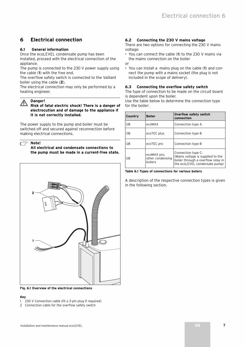
6.1 General informationOnce the ecoLEVEL condensate pump has been installed, proceed with the electrical connection of the appliance.The pump is connected to the 230 V power supply using the cable (1) with the free end.The overflow safety switch is connected to the Vaillant boiler using the cable (2).The electrical connection may only be performed by a heating engineer.
Danger!Risk of fatal electric shock! There is a danger of electrocution and of damage to the appliance if it is not correctly installed.
The power supply to the pump and boiler must be switched off and secured against reconnection before making electrical connections.
Note!All electrical and condensate connections to the pump must be made in a current-free state.
1
2
Fig. 6.1 Overview of the electrical connections
Key1 230 V Connection cable (fit a 3-pin plug if required)2 Connection cable for the overflow safety switch
6.2 Connecting the 230 V mains voltageThere are two options for connecting the 230 V mains voltage:• You can connect the cable (1) to the 230 V mains via
the mains connection on the boileror• You can install a mains plug on the cable (1) and con-
nect the pump with a mains socket (the plug is not included in the scope of delivery).
6.3 Connecting the overflow safety switchThe type of connection to be made on the circuit board is dependent upon the boiler.Use the table below to determine the connection type for the boiler:
Country BoilerOverflow safety switch connection
GB ecoMAX Connection type A
GB ecoTEC plus Connection type B
GB ecoTEC pro Connection type B
GBecoMAX pro, other condensing boilers
Connection type C:(Mains voltage is supplied to the boiler through a overflow relay in the ecoLEVEL condensate pump)
Table 6.1 Types of connections for various boilers
A description of the respective connection types is given in the following section.
Electrical connection 6

8 Installation and maintenance manual ecoLEVEL
Connection type A (ecoMAX):Connect the overflow safety switch to the boiler‘s low voltage circuit in the following manner: • Open the boiler electrical box.• Remove the cable bridge from the blue slot (“Anl-
Therm”) on the circuit board. • Plug the blue Pro E plug on the end of the ecoLEVEL
condensate cable into this slot.
98
75
43
NL
NL
Pu
mp
e 2
. Pu
mp
eA
nl -
Th
erm
L N
24
V I
23
0V
RT
24
V2
30
VR
T 2
30
V
X 10
X 7
X 8
X 2
13
11
1
1
Co
die
rwid
erstan
d
1
2
Fig. 6.2 Connecting the overflow safety switch, connection
type A
6 Electrical connection

9Installation and maintenance manual ecoLEVEL GB
Electrical connection 6
Connection type B (ecoTEC):Connect the overflow safety switch to the boiler‘s low voltage circuit in the following manner: • Open the boiler electrical box.• Plug the matching plug into the X40 slot on the boiler
PCB.
If the boiler has a built-in 2 from 7 multi-func-tion module (item no. 00 2001 7744), the X40 connection is already assigned. In this case, plug the connector to X40B on the 2 from 7 multi-function module.See also the multi-function module instruc-tions.
1
Fig. 6.3 Connecting the overflow safety switch,
connection type B
Connection type C:When installed as shown here, the condensate pump will isolate the boiler in the event that the pump fails or in the event that the overflow safety switch in the pump is activated, e.g. if it is blocked. This will prevent the boiler from continuing to produce condensate and prevent the risk of flooding.Connect the overflow safety switch to the boiler in the following manner: • Using a suitable cutting tool, cut off both plugs at the
end of the cable (2, Fig. 6.1) and remove the insulation from the ends of the wires.
• Connect with the mains voltage connection on the boiler as shown in Fig. 6.4.
• Connect to the 230 V mains voltage connection on the ecoLEVEL condensate pump as shown in Sec. 6.2.
PE L1 N230 V ~
230 V ~
Boiler
Fig. 6.4 Connecting the overflow safety switch, connection
type C

10 Installation and maintenance manual ecoLEVEL
7 Start-up
Once the ecoLEVEL condensate pump has been mechanically and electrically installed, it is ready for operation. The green LED lights up.
Note!Once the pump has been installed and put into service, operation is self-regulating and does not require further attendance.
7.1 Display of operating statusOn the front edge of the housing there are two integrat-ed diodes which indicate the operating status of the ecoLEVEL condensate pump.The green LED signals the following statuses:
Green LED Red LED Meaning
Lights up Off Pump has 230 V mains voltage supply
Flashes OffPump is operating and pumping out condensate
If the red LED lights up or flashes, a malfunc-tion has occurred. See section 9.
8 Maintenance
Danger!Risk of fatal electric shock from touching live connections. Always switch off the power sup-ply to the pump and boiler first. You may only proceed with the maintenance once this has been done.
• Make sure that the inflow and outflow are unobstruct-ed.
• Remove the cover from the pump and inspect the con-densate reservoir for contamination. If necessary, clean the condensate reservoir with warm water and a mild cleaning agent.
• Disassemble the non-return valve and clean it under running water.
• Inspect the feed and discharge hoses and clean them if necessary.
• In order to ensure an unobstructed flow, make sure that the hoses are not kinked.
Note!Maintenance on the pump can be scheduled to coincide with the maintenance intervals for the boiler. The pump should be serviced at least once a year.
9 Troubleshooting
9.1 ProblemsThe ecoLEVEL condensate pump can rectify temporary faults during normal operation by itself. The red LED sig-nals the following operating conditions:
Green LED Red LED Meaning
Flashes Lights upThe maximum water level in the pump has been exceeded.The container is pumped out.
Flashes FlashesThe pump remains in an idle state for a defined period, then starts up again automatically.
If the LED lights up or flashes, the water level has exceeded the maximum level and the overflow switch has been triggered. Either a zero-potential contact or the circuit is opened in order to switch off the boiler.If the required connection to the boiler has been installed, it will be switched off in order to prevent the further accumulation of condensate.
9.2 Fault diagnosisIf the red LED lights up or flashes for a lengthy period, there is a fault in the installation or a defect in the pump. Check the following points when troubleshooting:
Cause Troubleshooting
Pump is not discharging condensate:Runout hose is kinked
Remove the kink
Motor blockedVisually inspect the feed area: look for foreign objects and remove if found
Motor is defective Replace the condensate pump
Pump not being filled
Check the position of the hose, inspect for blockage, make sure it is properly attached to the pump, correct the problem if found
Water guage float is blocked
Ensure the float can move freely
7 Start-up8 Maintenance9 Troubleshooting

11Installation and maintenance manual ecoLEVEL GB
Customer service 10Technical data 11
10 Customer service
Vaillant customer serviceTo ensure regular servicing, it is strongly recommended that arrangements are made for a Maintenance Agreement. Please contact Vaillant Service Solutions (0870 6060 777) for further details.
11 Technical data
Technical data Units ecoLEVEL
Design Appliance for wall-mounted installation
Nominal capacity l 0,5
Mains voltage V 230
Max. current consumption A 1
Frequency Hz 50
Max. power rating W 22
Max. pump head m 4
Volume flow l/h 150
Dimensions Height mm 160
Width mm 180
Depth mm 100
Weight when filled with water kg 1,8
Feed hose (max. outside diameter) mm 24
Discharge hose (min. inside diameter) mm 10
Water infeed temperature °C 1 ... 60
Ambient temperature °C 5 ... 60
Safety Radio-shielded, non-interacting with the mains supply
Overflow circuit breaker 5 mA ...4 A; 230 V
Level of protection according to EN 60529 IP 44
Table 11.1 Technical data

1Bedienungsanleitung ecoLEVEL DE; AT;CHDE; BEDE
Inhaltsverzeichnis
1 Hinweise zur Dokumentation . . . . . . . . . . . . . 21.1 Aufbewahrung der Unterlagen . . . . . . . . . . . . . . . 21.2 Verwendete Symbole . . . . . . . . . . . . . . . . . . . . . . . . 2
2 Sicherheitshinweise und Vorschriften . . . . . . 2
3 Hinweise zum Betrieb . . . . . . . . . . . . . . . . . . . 33.1 Werksgarantie und Haftung . . . . . . . . . . . . . . . . . . 33.2 Bestimmungsgemäße Verwendung . . . . . . . . . . . 33.3 Pflege . . . . . . . . . . . . . . . . . . . . . . . . . . . . . . . . . . . . . 33.4 Recycling und Entsorgung . . . . . . . . . . . . . . . . . . . 3
4 Bedienung und Wartung . . . . . . . . . . . . . . . . . 34.1 Allgemeine Informationen . . . . . . . . . . . . . . . . 34.2 Anzeige des Betriebsstatus . . . . . . . . . . . . . . . . . . 34.3 Wartung . . . . . . . . . . . . . . . . . . . . . . . . . . . . . . . . . . . 4
Für den Betreiber
Bedienungsanleitung
ecoLEVEL
Kondenswasserpumpe

2 Bedienungsanleitung ecoLEVEL
1 Hinweise zur Dokumentation
Die folgenden Hinweise sind ein Wegweiser durch die Gesamtdokumentation.In Verbindung mit dieser Bedienungs-, Installations- und Wartungs anleitung sind weitere Unterlagen gültig.Für Schäden, die durch Nichtbeachtung dieser Anlei-tungen entstehen, übernehmen wir keine Haftung.
Mitgeltende UnterlagenBitte beachten Sie bei der Bedienung der Kondens-wasserpumpe ecoLEVEL alle Bedienungs anleitungen von Bauteilen und Kompo nenten der Anlage. Diese Bedienungsanleitungen sind den jeweiligen Bauteilen der Anlage sowie ergänzen den Komponenten beigefügt.
1.1 Aufbewahrung der UnterlagenBewahren Sie bitte diese Bedienungs-, Installations- und Wartungs anleitung sowie alle mitgeltenden Unterlagen so auf, dass sie bei Bedarf zur Verfügung stehen. Übergeben Sie bei Auszug oder Verkauf die Unterlagen an den Nachfolger.
1.2 Verwendete SymboleBeachten Sie bitte bei der Bedienung die Sicherheitshin-weise in dieser Bedienungsanlei tung!
Gefahr!Lebensgefahr durch Stromschlag!
Gefahr!Unmittelbare Gefahr für Leib und Leben!
Achtung!Mögliche gefährliche Situation für Produkt und Umwelt!
Hinweis!Nützliche Informationen und Hinweise.
• Symbol für eine erforderliche Aktivität
2 Sicherheitshinweise und Vorschriften
Änderungen an der Kondenswasserpumpe ecoLEVEL sind generell verboten. Für Änderungen im Umfeld müssen Sie einen zuständigen Fachhandwerksbetrieb hinzuziehen.
Achtung!Beschädigungsgefahr durch unsachgemäße Veränderungen!Nehmen Sie unter keinen Umständen Eingriffe oder Manipulationen an der Pumpe oder an anderen Teilen der Anlage vor.
Installation, Inbetriebnahme und Betrieb
Gefahr!Gefahr durch lebensgefährliche Spannungen!Im Gerät und an den Zuleitungen sind lebensgefährliche Spannungen vorhanden. Das Gerät darf deshalb ausschließlich von einem Fachhandwerksbetrieb installiert oder geöffnet werden.
Dieser übernimmt auch die Verantwortung für die ordnungsgemäße Installation und Inbetriebnahme. Er ist ebenfalls für die Inspektion/Wartung der Kondens-wasserpumpe ecoLEVEL zuständig.- Benutzen Sie die Pumpe nicht zum Abpumpen von
brennbaren und explosiven Flüssigkeiten wie Benzin, Heizöl etc.! Es besteht die Gefahr von Verbrennungen und Explosionen.
- Benutzen Sie die Pumpe nicht in einer explosiven Atmosphäre, da es beim Betrieb der Pumpe zu einer Explosion kommen könnte.
KondensatDas in der Pumpe geförderte Kondensat stellt bei Berührung eine Gefahr für die Augen dar. Beachten Sie, dass die Kondenswasserpumpe ecoLEVEL außerhalb der Reichweite von Kindern betrieben werden sollte.
1 Hinweise zur Dokumentation2 Sicherheitshinweise und Vorschriften

3Bedienungsanleitung ecoLEVEL DE; AT;CHDE; BEDE
3 Hinweise zum Betrieb
3.1 Werksgarantie und HaftungWerksgarantie gewähren wir nur bei Installation durch einen anerkannten Fachhandwerksbetrieb. Dem Eigen-tümer des Gerätes räumen wir eine Werksgarantie von 2 Jahren ein. Garantiearbeiten werden grundsätzlich nur von unserem Werkskundendienst ausgeführt. Wir können Ihnen daher etwaige Kosten, die Ihnen bei der Durchführung von Arbeiten an dem Gerät während der Garantiezeit entstehen, nur dann erstatten, wenn wir Ihnen einen entsprechenden Auftrag erteilt haben und es sich um einen Garantiefall handelt.
3.2 Bestimmungsgemäße VerwendungDie Kondenswasserpumpe ecoLEVEL ist nur in Verbin-dung mit Vaillant Systemkomponenten zu verwenden, in denen betriebsbedingt Kondenswasser als Nebenprodukt anfällt. Hierunter fallen alle Vaillant Brennwert-Heiz-geräte. Die Pumpe ist in all ihren Komponenten auf die Förde-rung von Kondenswasser aus Heizungsan lagen ausge-legt. Hierbei ist bereits die abgassystem bedingte Ein-bringung von Regenwasser in das System berücksichtigt. Dies bezieht sich sowohl auf die zulässige Menge, die Zusammen setzung als auch auf die Festkörperbestand-teile im Kondensat.Die Kondenswasserpumpe ist nicht dazu geeignet andere flüssige oder feste Medien zu fördern. Insbesondere Abwässer jeglicher Art, Chemikalien sowie ölhaltige Emulsionen dürfen nicht in die Kondenswasser -pumpe eingeleitet werden. Eine andere Benutzung, als die hier beschriebene, insbesondere die Förderung nicht zugelassener Medien, gilt als nicht bestimmungsgemäß. Für hieraus resultierende Schäden haftet der Hersteller/Lieferant nicht. Das Risiko trägt allein der Betreiber.Zur bestimmungsgemäßen Verwendung gehört auch die Beachtung der Bedienungs-, Installations- und Wartungs -anleitung.
Achtung!Jede missbräuchliche Verwendung ist untersagt.
3.3 PflegeReinigen Sie die Oberfläche mit einem feuchten Tuch. Verwenden Sie keine scharfen Reinigungsmittel!
3.4 Recycling und EntsorgungSowohl die Pumpe als auch die zugehörige Transport-verpackung bestehen zum überwiegenden Teil aus recyclefähigen Rohstoffen.
GerätDefekte Pumpen wie auch alle Zubehöre gehören nicht in den Hausmüll. Sorgen Sie dafür, dass das Alt gerät und
ggf. vorhandene Zubehöre einer ordnungsgemäßen Entsorgung für Elektrogeräte zugeführt werden.
VerpackungDie Entsorgung der Transportverpackung überlassen Sie bitte dem Fachhandwerksbetrieb, der das Gerät installiert hat.
4 Bedienung und Wartung
4.1 Allgemeine InformationenDie Kondenswasserpumpe ecoLEVEL wird zum Ab -pumpen von anfallendem Kondenswasser bei Brennwert-Heizungs anlagen eingesetzt. Das anfallende Kondens-wasser der Brennwertanlage gelangt durch einen Ein-laufschlauch in den Behälter der Pumpe.Durch eine kontinuierliche Messung des Wasserstandes wird die Pumpe bei Erreichen des höchsten Füllstandes selbsttätig eingeschaltet und das Kondensat durch den Auslaufschlauch abgepumpt.Die Kondenswasserpumpe ecoLEVEL verfügt über einen Sicherheits-Überlaufschalter. Dieser schaltet das Heiz-gerät bei entsprechendem Anschluss automatisch ab, um im Falle einer Störung das Überlaufen von Kondens-wasser zu verhindern.
Hinweis!Nach der Installation und Inbetriebnahme der Pumpe ist der Betrieb selbstregelnd und bedarf keiner weiteren Bedienung.
4.2 Anzeige des BetriebsstatusIn der vorderen Kante des Gehäuses sind zwei Dioden integriert, welche den Betriebsstatus der Kondens-wasserpumpe ecoLEVEL anzeigen.Wenn die Pumpe mit der 230 V Netzspannung versorgt ist, leuchtet die grüne LED. Dies bedeutet, dass die Pumpe betriebsbereit ist.Die rote LED zeigt an, dass der Wasserstand den höch-sten zulässigen Wert überschritten hat und der Sicherheits-Überlaufschalter ausgelöst wurde.Sofern eine entsprechende Verbindung zum Heizgerät installiert wurde, wird dieses ausgeschaltet, um die Entstehung von weiterem Kondenswasser zu verhindern.
Hinweis!Falls die rote LED über einen längeren Zeitraum blinkt oder leuchtet, liegt ein Fehler in der Installation oder ein Defekt der Pumpe vor.Beauftragen Sie einen Fachhandwerksbe trieb mit der Über prüfung und Instandsetzung der Pumpe.
Hinweise zum Betrieb 3Bedienung und Wartung 4

4 Bedienungsanleitung ecoLEVEL
4.3 WartungLassen Sie die Kondenswasserpumpe ecoLEVEL mindestens alle 2 Jahre von einem Fachhandwerks-betrieb überprüfen und reinigen.
4 Bedienung und Wartung

1Installations- und Wartungsanleitung ecoLEVEL DE; AT;CHDE; BEDE
Inhaltsverzeichnis
1 Hinweise zur Dokumentation . . . . . . . . . . . . . 21.1 Anbringung und Aufbewahrung der Unterlagen 21.2 Verwendete Symbole . . . . . . . . . . . . . . . . . . . . . . . . 21.3 CE-Kennzeichnung . . . . . . . . . . . . . . . . . . . . . . . . . . 21.4 Typenschild . . . . . . . . . . . . . . . . . . . . . . . . . . . . . . . . 2
2 Sicherheitshinweise und Vorschriften . . . . . . 2
3 Hinweise zu Installation und Betrieb . . . . . . . 33.1 Werksgarantie und Haftung . . . . . . . . . . . . . . . . . . 33.2 Bestimmungsgemäße Verwendung . . . . . . . . . . . 33.3 Recycling und Entsorgung . . . . . . . . . . . . . . . . . . . 4
4 Montage . . . . . . . . . . . . . . . . . . . . . . . . . . . . . . 44.1 Lieferumfang . . . . . . . . . . . . . . . . . . . . . . . . . . . . . . 44.2 Auswahl des Montageortes . . . . . . . . . . . . . . . . . . 44.3 Abmessungen und Montagefreiräume . . . . . . . . . 44.4 Wandhalter montieren . . . . . . . . . . . . . . . . . . . . . . 4
5 Installation . . . . . . . . . . . . . . . . . . . . . . . . . . . . 55.1 Anschluss des Einlaufschlauchs . . . . . . . . . . . . . . 5
5.2 Anschluss und Verlegung des Auslauf-schlauches . . . . . . . . . . . . . . . . . . . . . . . . . . . . . . . . . 6
5.3 Anschluss an das Heizgerät . . . . . . . . . . . . . . . . . . 6
6 Elektrischer Anschluss . . . . . . . . . . . . . . . . . . 76.1 Allgemeines . . . . . . . . . . . . . . . . . . . . . . . . . . . . . . . . 76.2 Anschluss der 230 V Netzspannung . . . . . . . . . . . 76.3 Anschluss des Sicherheits-Überlaufschalter . . . . 7
7 Inbetriebnahme . . . . . . . . . . . . . . . . . . . . . . . . 107.1 Anzeige des Betriebsstatus . . . . . . . . . . . . . . . . . . 10
8 Wartung . . . . . . . . . . . . . . . . . . . . . . . . . . . . . . 10
9 Diagnose und Störungsbehebung . . . . . . . . . . 109.1 Störungen . . . . . . . . . . . . . . . . . . . . . . . . . . . . . . . . . 109.2 Fehlerdiagnose . . . . . . . . . . . . . . . . . . . . . . . . . . . . . 10
10 Kundendienst . . . . . . . . . . . . . . . . . . . . . . . . . . 11
11 Technische Daten . . . . . . . . . . . . . . . . . . . . . . 11
Für den Fachhandwerker
Installations- und Wartungsanleitung
ecoLEVEL
Kondenswasserpumpe

2 Installations- und Wartungsanleitung ecoLEVEL
1 Hinweise zur Dokumentation
Die folgenden Hinweise sind ein Wegweiser durch die Gesamtdokumentation.In Verbindung mit dieser Bedienungs-, Installations- und Wartungs anleitung sind weitere Unterlagen gültig.Für Schäden, die durch Nichtbeachtung dieser Anlei-tungen entstehen, übernehmen wir keine Haftung.
Mitgeltende UnterlagenBitte beachten Sie bei der Installation der Kondens-wasserpumpe alle Montage- und Installationsanleitungen von Bauteilen und Kompo nenten der Anlage. Diese Anleitungen sind den jeweiligen Bauteilen der Anlage sowie ergänzen den Komponenten beigefügt.
1.1 Anbringung und Aufbewahrung der UnterlagenGeben Sie bitte diese Bedienungs-, Installations- und Wartungsan leitung an den Anlagen betreiber weiter. Dieser über nimmt die Aufbewahrung, damit die Anleitungen bei Bedarf zur Verfügung stehen.
1.2 Verwendete SymboleBeachten Sie bitte bei der Installation und Wartung der Kondenswasserpumpe die Sicherheits-Hinweise in dieser Anlei tung!
Gefahr!Lebensgefahr durch Stromschlag!
Gefahr!Unmittelbare Gefahr für Leib und Leben!
Achtung!Mögliche gefährliche Situation für Produkt und Umwelt!
Hinweis!Nützliche Informationen und Hinweise.
• Symbol für eine erforderliche Aktivität
1.3 CE-KennzeichnungMit der CE-Kennzeichnung wird dokumentiert, dass die Kondenswasserpumpe ecoLEVEL gemäß dem Typen-schild die grundlegenden Anforderungen folgender einschlägiger Richt linien erfüllt:- Zulässige Spannungen (Richtlinien EN 60 335-1 und
EN 60 335-2-41)- Elektromagnetische Verträglichkeit (Richtlinien
EN 55 014-1 und EN 55 014-2)
1.4 TypenschildDas Typenschild mit der Serialnummer, der Schutzklasse, der Versorgungs spannung, der Frequenz und der CE Kennzeichnung befindet sich auf der Unterseite der Kondenswasserpumpe ecoLEVEL.
2 Sicherheitshinweise und Vorschriften
Achtung!Gefahr durch lebensgefährliche Spannungen!Im Gerät und an den Zuleitungen sind lebensgefährliche Spannungen vorhanden. Das Gerät darf deshalb ausschließlich von einem Fachhandwerksbetrieb installiert und geöffnet werden.
Normen und VorschriftenIEC 60364-7-712 Electrical installations of buildings - Part 7-712EMV-Prüfverfahren gemäß EN50081-1:1992,EN50082-1:1997 Störaussendung: EN 55014-1: 1993 Störfestigkeit: EN 55014-2: 1997
Regeln der TechnikDie Montage muss den bauseitigen Bedingungen, den örtlichen Vorschriften und nicht zuletzt den Regeln der Technik entsprechen. Hier sind insbesondere zu nennen:- Elektrischer Anschluss
VDE 0100 Errichten von Starkstromanlagen mit Nennspannungen bis 1000 Volt,VDE 0105 Teil 100 Betrieb von elektrischen AnlagenDIN 18382 Elektrische Kabel- und Leitungsanlage in Gebäuden (gilt nur in Deutschland)
UnfallverhütungsvorschriftenDie Kondenswasserpumpe muss von einem anerkannten Fachhandwerksbetrieb installiert werden. Dieser ist für die Beachtung bestehender Normen und Vorschriften verantwortlich.Der einwandfreie und sichere Betrieb dieses Gerätes setzt sachgemäßen Transport, fachgerechte Lagerung, Aufstellung und Montage sowie sorgfältige Bedienung und Instandhaltung voraus.
Nur Fachhandwerker, die sich zuvor mit allen in dieser Bedienungs- und Installationsanleitung enthaltenen Sicherheitshinwei sen sowie Montage-, Betriebs- und Wartungsanweisun gen vertraut gemacht haben, dürfen an diesem Gerät arbeiten.Beim Betrieb dieses Gerätes stehen zwangsläufig bestimmte Geräteteile unter gefährlicher Spannung, die zu schweren Körperverletzungen oder zum Tod führen kann.Die folgenden Vorsichtsmaßnahmen müssen befolgt werden, um die Gefahr für das Leben bzw. die Verlet-zungs gefahr zu verringern:1. Die Montage des Gerätes muss in Übereinstimmung
mit den Sicherheitsvorschriften sowie allen anderen relevanten staatlichen oder örtlichen Vorschriften erfolgen. Es muss für ordnungsgemäße Erdung, Leiterdimensionierung und entsprechenden Kurz-schluss schutz gesorgt sein, um die Betriebssicher heit zu gewährleisten.
1 Hinweise zur Dokumentation2 Sicherheitshinweise und Vorschriften

3Installations- und Wartungsanleitung ecoLEVEL DE; AT;CHDE; BEDE
2. Das Öffnen des Bodendeckels ist nur durch Fach-personal zulässig. Der Bodendeckel darf nur geöffnet werden, wenn alle elek trischen Verbindungen von der Pumpe getrennt sind.
3. Vor der Durchführung von Sichtprüfungen und War-tungsarbeiten sicherstellen, dass die Stromversorgung abgeschaltet und gegen Wiedereinschalten gesichert ist. Wenn Messungen bei eingeschalteter Stromversorgung durchgeführt werden müssen, keinesfalls die elektrischen Anschluss stellen berühren. Allen Schmuck von Handgelenken und Fingern abnehmen. Sicherstellen, dass die Prüfmittel in gutem, betriebssicherem Zustand sind.
4. Bei Arbeiten am eingeschalteten Gerät auf isoliertem Untergrund stehen, also sicherstellen, dass keine Erdung vorliegt.
5. Die in dieser Bedienungs- und Installations- und Wartungsanleitung gegebenen Anweisun gen genau befolgen und alle Gefahren-, Warn- und Vorsichts-hinweise beachten.
6. Diese Liste stellt keine vollständige Aufzählung aller für den sicheren Betrieb des Gerätes erforderlichen Maßnahmen dar. Sollten spezielle Probleme auftreten, die für die Zwecke des Käufers nicht ausführlich genug behandelt werden, wenden Sie sich bitte an Ihren Fachhändler.
Sicherheitshinweise- Benutzen Sie die Pumpe nicht zum Abpumpen von
brennbaren und explosiven Flüssigkeiten wie Benzin, Heizöl etc.! Es besteht die Gefahr von Verbrennungen und Explosionen.
- Benutzen Sie die Pumpe nicht in einer explosiven Atmosphäre, da es beim Betrieb der Pumpe zu einer Explosion kommen könnte.
- Der Pumpenanschluss verfügt über einen Schutzleiter.Stellen Sie sicher, dass die Stromversorgung gemäß der gesetzlichen Bestimmungen geerdet ist.
- Schließen Sie an den Sicherheitsschalter eine Strom -unterbrechung oder einen Alarm an, um bei einem Defekt an der Pumpe Schäden durch austretendes Kondenswasser oder Schäden am Heizgerät zu ver-meiden.
- Stellen Sie sicher, dass die Pumpe während des Betriebs einen sicheren Stand hat oder an der Wand befestigt ist, da es sonst zu Funktionsstörungen der Pumpe kommen kann. Diese können zu Schäden an der Pumpe oder am Heizgerät führen.
- Verbinden Sie den Kondenswasserauslaufschlauch der Pumpe nicht dicht mit der Abwasserleitung.Vergiftungsgefahr durch Abgasaustritt! Der interne Siphon des Heizgeräts könnte leergesaugt werden.
- Muss bei der Installation die Kondenswasserablauf-leitung verlängert werden, sind nur zulässige Ablaufrohre nach DIN 1986-4 zu verwenden. Bei Verwendung von ungeeigneten Ablaufrohren kann es zu Undichtigkeiten und Schäden durch Austretendes Kondenswasser kommen.
VeränderungenÄnderungen an der Pumpe sind generell verboten. Änderungen im Umfeld sind nur zulässig, sofern sie den nationalen Normen entsprechen.
Achtung!Beschädigungsgefahr durch unsachgemäße Veränderungen!Nehmen Sie unter keinen Umständen Eingriffe oder Manipulationen an der Pumpe oder an anderen Teilen der Anlage vor.
3 Hinweise zu Installation und Betrieb
3.1 Werksgarantie und HaftungWerksgarantie gewähren wir nur bei Installation durch einen anerkannten Fachhandwerksbetrieb. Dem Eigen-tümer des Gerätes räumen wir eine Werksgarantie von 2 Jahren ein. Garantiearbeiten werden grundsätzlich nur von unserem Werkskundendienst ausgeführt. Wir können Ihnen daher etwaige Kosten, die Ihnen bei der Durchführung von Arbeiten an dem Gerät während der Garantiezeit entstehen, nur dann erstatten, wenn wir Ihnen einen entsprechenden Auftrag erteilt haben und es sich um einen Garantiefall handelt.
3.2 Bestimmungsgemäße VerwendungDiese Kondenswasserpumpe ist nur in Verbindung mit Vaillant Systemkomponenten zu verwenden, in denen betriebsbedingt Kondenswasser als Nebenprodukt anfällt. Hierunter fallen alle Vaillant Brennwert-Heiz-geräte. Die Kondenswasserpumpe ist in all ihren Komponenten auf die Förderung von Kondenswasser aus Heizungsan-lagen ausgelegt. Hierbei ist bereits die abgassystem -bedingte Einbringung von Regenwasser in das System berücksichtigt. Dies bezieht sich sowohl auf die zulässige Menge, die Zusammensetzung als auch auf die Festkörperbestandteile im Kondensat.Die Kondenswasserpumpe ist nicht dazu geeignet, andere flüssige oder feste Medien zu fördern. Insbesondere Abwässer jeglicher Art, Chemikalien sowie ölhaltige Emulsionen dürfen nicht in die Kondens-wasserpumpe eingeleitet werden. Eine andere Benutzung, als die hier beschriebene, insbesondere die Förderung nicht zugelassener Medien, gilt als nicht bestimmungsgemäß. Für hieraus resultierende Schäden haftet der Hersteller/Lieferant nicht. Das Risiko trägt allein der Betreiber.Zur bestimmungsgemäßen Verwendung gehört auch die Beachtung der Installations- und Wartungsanleitung.
Achtung!Jede missbräuchliche Verwendung ist unter-sagt.
Sicherheitshinweise und Vorschriften 2Hinweise zu Installation und Betrieb 3

4 Installations- und Wartungsanleitung ecoLEVEL
3.3 Recycling und EntsorgungSowohl die Pumpe als auch die zugehörige Transport-verpackung bestehen zum überwiegenden Teil aus recyclefähigen Rohstoffen.
GerätDefekte Pumpen wie auch alle Zubehöre gehören nicht in den Hausmüll. Sorgen Sie dafür, dass das Alt gerät und ggf. vorhandene Zubehöre einer ordnungsgemäßen Entsorgung für Elektrogeräte zugeführt werden.
VerpackungDie Entsorgung der Transportverpackung überlassen Sie bitte dem Fachhandwerksbetrieb, der das Gerät installiert hat.
4 Montage
4.1 Lieferumfang
Bezeichnung Abmessungen Anzahl
Kondenswasserpumpe 180 x 160 x 100 mm 1
Montagedübel 5 mm 2
Schrauben 4 x 35 mm 2
Einlaufschlauch Ø 24 mm x 1,15 m 1
Auslaufschlauch Ø 10 mm x 6 m 1
Wandhalter - 1
Wandhalter für Auslauf-schlauch
- 6
Bedienungs-, Installations- und Wartungsanleitung
- 1
Tab. 4.1 Lieferumfang
Sie benötigen zur Montage folgende Werkzeuge:- Bohrmaschine- Bohrer (5 mm)- Schlitzschraubendreher- Wasserwaage- Schneidklinge- Werkzeuge zum elektrischen Anschluss
4.2 Auswahl des MontageortesDie Kondenswasserpumpe ecoLEVEL ist für die Installation im Aufstellraum des Heizgerätes vorge sehen. Die Umgebungstemperatur muss zwischen 5 °C und 60 °C liegen.Der Aufstellungraum sollte eine Wandbeschaffenheit aufweisen, welche den Einsatz der mitgelieferten Verbindungselemente ermöglicht. Sollte dieses nicht gewährleistet sein, so müssen Sie eine entsprechende Montagefläche schaffen. Die Kondenswasserpumpe ecoLEVEL sollte nicht als Ablage für Gegenstände dienen.
4.3 Abmessungen und Montagefreiräume
100 mm
90 mm
165 mm
115
mm
150
mm
175 mm
min
. 20
0 m
m
min. 5 mm min. 5 mm
min
. 20
0 m
m
min. 5 mm min. 5 mm
Abb. 4.1 Abmessungen und Montagefreiräume
4.4 Wandhalter montieren• Führen Sie den vormontierten Wandhalter nach unten
aus dem Gehäuse der Kondenswasserpumpe heraus.• Montieren Sie den Wandhalter gemäß Abbildung 4.2
an einer geeigneten Stelle unterhalb der Kondensat-aus laufstelle des Heizgerätes.Der Wandhalter muss waagerecht montiert werden! Verwenden Sie eine Wasserwaage!
• Schieben Sie die Kondenswasserpumpe gerade von oben auf die Führungskanten des Wandhalters.In der untersten Position arretiert ein kleiner Haken die Pumpe am Halter.
Hinweis!Die Kondenswasserpumpe kann sowohl an der schmalen Seite als auch an der breiten Rück-seite gemäß Abb. 4.1 im Halter befestigt werden.
3 Hinweise zu Installation und Betrieb4 Montage

5Installations- und Wartungsanleitung ecoLEVEL DE; AT;CHDE; BEDE
A
B
Abb. 4.2 Montage des Wandhalters
5 Installation
Achtung!Schließen Sie die Schläuche an, wenn das Rückschlagventil (1) und der Deckel (2) demontiert sind.Pumpe und Wandhalter können durch zu hohe Kräfte bei der Montage beschädigt werden.
5.1 Anschluss des Einlaufschlauchs
Achtung!Der Einlaufschlauch muss mit konstantem Gefälle ohne Schlaufen im Schlauch vom Heizgerät zur Kondens wasserpumpe ecoLEVEL verlegt werden, da das Kondenswasser sonst nicht ungehindert in die Pumpe abfließen kann.
• Bestimmen Sie die erforderliche Länge des Schlauches.
• Kürzen Sie den Schlauch so, dass noch mindestens 10 mm Einstecktiefe in den Deckel der Pumpe am Schlauchende verbleiben.
• Drehen Sie das Rückschlagventil (1) eine Viertel-drehung nach links, um den Deckel (2) der Pumpe zu öffnen.Danach sind sowohl der Deckel als auch das Rück-schlag ventil entriegelt.
• Ziehen Sie den Deckel und das Rückschlagventil nach oben ab.
1
3
4 2
Abb. 5.1 Rückschlagventil und Deckel demontieren
• Stecken Sie den Einlaufschlauch in eine Einlauföffnung (3) des abgenommenen Deckels, bis der Einlauf-schlauch einrastet.
Hinweis!Falls ein zweiter Schlauch angeschlossen werden soll, entfernen Sie den Stopfen von der zweiten Einlauföffnung (4) und schließen Sie den zusätzlichen Schlauch an, wie oben be -schrieben.
• Setzen Sie den Deckel von oben auf die Kondens-wasserpumpe ecoLEVEL auf.
Montage 4Installation 5

6 Installations- und Wartungsanleitung ecoLEVEL
5.2 Anschluss und Verlegung des Auslaufschlauches
• Stecken Sie den Auslaufschlauch bis zum Anschlag auf das demontierte Rückschlagventil.
• Führen Sie das Rückschlagventil in den Deckel ein und arretieren es durch eine Vierteldrehung nach rechts.
Verlegung des Auslaufschlauchs:Der Auslaufschlauch der Pumpe sollte im Abwasser-system des Aufstellungsgebäudes münden.• Führen Sie den Auslaufschlauch direkt von der Pumpe
weit genug nach oben, um den Höhen unterschied zwischen dem Ausgang der Pumpe und der Ablauf -stelle zu über winden und den Auslaufschlauch nach der Umlenkung mit Gefälle zur Ablaufstelle verlegen zu können.
Achtung!Beachten Sie die maximale Förderhöhe der Pumpe von 4 m!
• Verlegen Sie den Auslaufschlauch dann mit stetigem Gefälle bis zu einer geeigneten Ablaufstelle.
• Verlegen Sie den Auslaufschlauch an der höchsten Stelle U-förmig zu einer Rückflusssicherung.
m
ax. 4
,0 m
ca 3˚
Abb. 5.2 Verlegung des Auslaufschlauchs
5.3 Anschluss an das HeizgerätMit Hilfe des mitgelieferten Einlaufschlauches kann die Kondenswasserpumpe ecoLEVEL an den Siphon aller Vaillant Brennwert-Heizgeräte angeschlossen werden.• Falls der Kondenswasser-Auslaufschlauch des Heiz-
gerätes lang genug ist, können Sie diesen direkt an die Pumpe anschließen (siehe Abschnitt 5.1).
Falls der Schlauch des Heizgerätes zu kurz sein sollte, ersetzen Sie ihn durch den mitgelieferten Einlauf-schlauch.• Schließen Sie den Einlaufschlauch an den Kondens-
wasser auslauf des Heizgerätes an.• Schließen den Einlaufschlauch gemäß Abschnitt 5.1 an
die Kondenswasserpumpe ecoLEVEL an.
5 Installation
7Installations- und Wartungsanleitung ecoLEVEL DE; AT;CHDE; BEDE
6 Elektrischer Anschluss
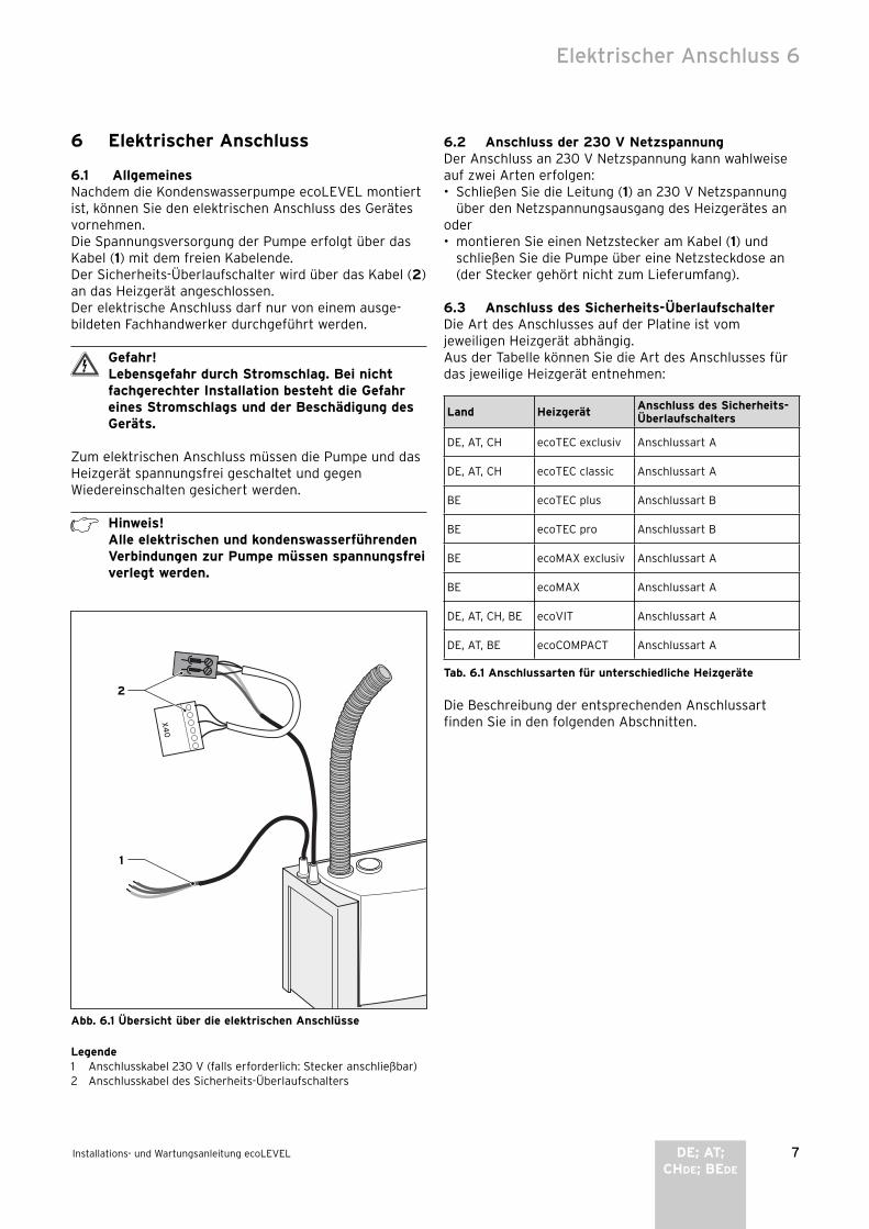
6.1 AllgemeinesNachdem die Kondenswasserpumpe ecoLEVEL montiert ist, können Sie den elek trischen Anschluss des Gerätes vornehmen.Die Spannungsversorgung der Pumpe erfolgt über das Kabel (1) mit dem freien Kabelende.Der Sicherheits-Überlaufschalter wird über das Kabel (2) an das Heizgerät angeschlossen.Der elektrische Anschluss darf nur von einem ausge-bildeten Fachhandwerker durchgeführt werden.
Gefahr!Lebensgefahr durch Stromschlag. Bei nicht fachgerechter Installation besteht die Gefahr eines Stromschlags und der Beschädigung des Geräts.
Zum elektrischen Anschluss müssen die Pumpe und das Heizgerät spannungsfrei geschaltet und gegen Wiederein schalten gesichert werden.
Hinweis!Alle elektrischen und kondenswasserführenden Verbindungen zur Pumpe müssen spannungsfrei verlegt werden.
1
2
Abb. 6.1 Übersicht über die elektrischen Anschlüsse
Legende1 Anschlusskabel 230 V (falls erforderlich: Stecker anschließbar)2 Anschlusskabel des Sicherheits-Überlaufschalters
6.2 Anschluss der 230 V NetzspannungDer Anschluss an 230 V Netzspannung kann wahlweise auf zwei Arten erfolgen:• Schließen Sie die Leitung (1) an 230 V Netzspannung
über den Netzspannungsausgang des Heizgerätes anoder• montieren Sie einen Netzstecker am Kabel (1) und
schließen Sie die Pumpe über eine Netzsteckdose an (der Stecker gehört nicht zum Lieferumfang).
6.3 Anschluss des Sicherheits-ÜberlaufschalterDie Art des Anschlusses auf der Platine ist vom jeweiligen Heizgerät abhängig.Aus der Tabelle können Sie die Art des Anschlusses für das jeweilige Heizgerät entnehmen:
Land HeizgerätAnschluss des Sicherheits-Überlaufschalters
DE, AT, CH ecoTEC exclusiv Anschlussart A
DE, AT, CH ecoTEC classic Anschlussart A
BE ecoTEC plus Anschlussart B
BE ecoTEC pro Anschlussart B
BE ecoMAX exclusiv Anschlussart A
BE ecoMAX Anschlussart A
DE, AT, CH, BE ecoVIT Anschlussart A
DE, AT, BE ecoCOMPACT Anschlussart A
Tab. 6.1 Anschlussarten für unterschiedliche Heizgeräte
Die Beschreibung der entsprechenden Anschlussart finden Sie in den folgenden Abschnitten.
Elektrischer Anschluss 6
8 Installations- und Wartungsanleitung ecoLEVEL
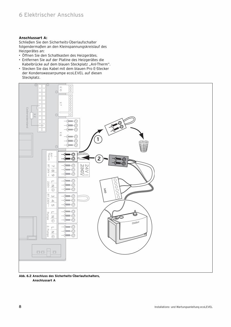
Anschlussart A:Schließen Sie den Sicherheits-Überlaufschalter folgendermaßen an den Kleinspannungskreislauf des Heizgerätes an:• Öffnen Sie den Schaltkasten des Heizgerätes.• Entfernen Sie auf der Platine des Heizgerätes die
Kabelbrücke auf dem blauen Steckplatz „Anl-Therm“. • Stecken Sie das Kabel mit dem blauen Pro E-Stecker
der Kondenswasserpumpe ecoLEVEL auf diesen Steckplatz.
98
75
43
NL
NL
Pu
mp
e 2
. Pu
mp
eA
nl -
Th
erm
L N
24
V I
23
0V
RT
24
V2
30
VR
T 2
30
V
X 10
X 7
X 8
X 2
13
11
1
1
Co
die
rwid
erstan
d
1
2
Abb. 6.2 Anschluss des Sicherheits-Überlaufschalters,
Anschlussart A
6 Elektrischer Anschluss

9Installations- und Wartungsanleitung ecoLEVEL DE; AT;CHDE; BEDE
Anschlussart B:Schließen Sie den Sicherheits-Überlaufschalter folgendermaßen an den Kleinspannungskreislauf des Heizgerätes an:• Öffnen Sie den Schaltkasten des Heizgerätes.• Stecken Sie den passenden Stecker auf den Rand-
steckplatz X40.
1
Abb. 6.3 Anschluss des Sicherheits-Überlaufschalters,
Anschlussart B
Hinweis!Ist im Heizgerät ein Multifunktionsmodul 2 aus 7 (Art.-Nr. 00 2001 7744) eingebaut, ist der Anschluss X40 bereits belegt. In diesem Fall wird der Stecker auf den Anschluss X40B des Multifunktionsmodul 2 aus 7 aufgesteckt.Siehe hierzu auch die Anleitung des Multi fun k-tions moduls.
Elektrischer Anschluss 6

10 Installations- und Wartungsanleitung ecoLEVEL
7 Inbetriebnahme
Nachdem die Kondenswasserpumpe ecoLEVEL mecha-nisch und elektrisch installiert wurde, ist sie betriebs-bereit. Die grüne LED leuchtet.
Hinweis!Nach der Installation und Inbetriebnahme der Pumpe ist der Betrieb selbstregelnd und bedarf keiner weiteren Bedienung.
7.1 Anzeige des BetriebsstatusIn der vorderen Kante des Gehäuses sind zwei Dioden intergriert, welche den Betriebsstatus der Kondens-wasserpumpe anzeigen.Die folgenden Statusanzeigen werden von der grünen LED signalisiert:
LED grün LED rot Bedeutung
Leuchtet AusPumpe ist mit 230 V Netzspannung versorgt
Blinkt AusPumpe ist in Betrieb und fördert Kondensat ab
Wenn die rote LED blinkt oder leuchtet, liegt eine Störung vor. Siehe Kapitel 9.
8 Wartung
Gefahr!Lebensgefahr durch Stromschlag an spannungs-führenden Anschlüssen. Schalten Sie immer zuerst die Stromzufuhr zur Pumpe und zum Heizgerät ab. Erst im Anschluss daran dürfen Sie die Wartung vornehmen.
• Stellen Sie sicher, dass die Zu- und Abflüsse frei sind.• Entfernen Sie den Pumpendeckel und kontrollieren Sie
den Kondensatbehälter auf Verunreinigungen. Falls notwendig, reinigen Sie den Kondensatbehälter mit warmem Wasser und einem milden Reiniger.
• Demontieren Sie das Rückschlagventil und reinigen dieses durch Spülen in einem Wasserstrahl.
• Kontrollieren Sie die Zu- und Abflussleitungen und reinigen diese, falls erforderlich.
• Stellen Sie sicher, dass die Leitungen nicht geknickt sind, um einen ungehinderten Durchfluss zu gewähr-leisten.
Hinweis!Die Wartung der Pumpe kann sich an die Wartungsintervalle des Heizgerätes anlehnen. Mindestens sollte die Pumpe einmal jährlich gewartet werden.
9 Diagnose und Störungsbehebung
9.1 StörungenDie Kondenswasserpumpe ecoLEVEL kann kurz fristige Störungen des normalen Funktionsablaufes selbsttätig beheben. Die folgenden Betriebszustände werden von der roten LED signalisiert:
LED grün LED rot Bedeutung
Blinkt LeuchtetDer höchste zulässige Wasserpegel in der Pumpe ist überschritten.Der Behälter wird leer gepumpt.
Blinkt BlinktDie Pumpe befindet sich für einen definierten Zeitraum in Ruhestellung und läuft selbsttätig wieder an.
Wenn die rote LED leuchtet oder blinkt, dann hat der Wasserstand den höch sten zulässigen Wert über-schritten und der Sicherheits-Überlaufschalter wurde ausgelöst. Es öffnet sich ein potentialfreier Kontakt bzw. der Stromkreis, um das Heizgerät abzuschalten.Sofern eine entsprechende Verbindung zum Heizgerät installiert wurde, wird das Heizgerät ausgeschaltet, um die Entstehung von weiterem Kondenswasser zu ver-hindern.
9.2 FehlerdiagnoseFalls die rote LED über einen längeren Zeitraum blinkt oder leuchtet, liegt ein Fehler in der Installation oder ein Defekt der Pumpe vor. Überprüfen Sie zur Störungsbehebung die folgenden Punkte:
Ursache Störungsbehebung
Pumpe fördert nicht:Auslaufschlauch geknickt
Knick beseitigen
Motor blockiertVisuelle Prüfung des Motoreinlaufes: Auf Fremdkörper kontrollieren und ggf. Fremdkörper entfernen
Motor defekt Kondenswasserpumpe austauschen
Pumpe wird nicht gefüllt
Einlaufschläuche auf Verlegung, Verstopfung und Sitz in der Pumpe kontrollieren, gegebenenfalls Fehler beseitigen
Hilfsschwimmer blockiert Hilfsschwimmer freigängig machen
7 Inbetriebnahme8 Wartung9 Diagnose und Störungsbehebung

11Installations- und Wartungsanleitung ecoLEVEL DE; AT;CHDE; BEDE
10 Kundendienst
Werkskundendienst DeutschlandVaillant Profi-Hotline 018 05/9 99-120
Werkskundendienst Vaillant GmbH (Österreich)Der Vaillant Werkskundendienst ist 365 Tage im Jahr von 0 bis 24.00 Uhr zum Ortstarif österreichweit unter 05 7050-2000 erreichbar.
Vaillant GmbH Werks kundendienst (Schweiz)Dietikon Tel.: (044) 744 29-39 Fax.: (044) 744 29-38Fribourg Tel.: (026) 409 72-17 Fax.: (026) 409 72-19
Vaillant GmbHPostfach 86Riedstr. 10CH-8953 DietikonTel.: (044) 744 29-29Fax: (044) 744 29-28
Werks kundendienst (Belgien)Vaillant sa-nvGolden Hopestraat 151620 DrogenbosTel : 02 334 93 52
11 Technische Daten
Technische Daten Einheiten ecoLEVEL
Bauform Gerät für Wandmontage
Nenninhalt l 0,5
Netzspannung V 230
Max. Strom A 1
Frequenz Hz 50
max. Nennleistung W 22
max. Förderhöhe m 4
Fördervolumen l/h 150
Abmessungen Höhe mm 160
Breite mm 180
Tiefe mm 100
Gewicht mit Wasserfüllung kg 1,8
Einlaufschlauch (max. Außendurchmesser) mm 24
Auslaufschlauch (min. Innendurchmesser) mm 10
Wassereinlauftemperatur °C 1 ... 60
Umgebungstemperatur °C 5 ... 60
Sicherheit funkentstört, netzrückwirkungsfrei
Überlauf-Schutzschalter 5 mA ...4 A; 230 V
Schutzart nach EN 60529 IP 44
Tab. 11.1 Technische Daten
Kundendienst 10Technische Daten 11


1Notice d‘emploi ecoLEVEL CHFR; BEFR
Table des matières
1 Remarques relatives à la documentation . . . . 21.1 Conservation des documents . . . . . . . . . . . . . . . . 21.2 Symboles utilisés . . . . . . . . . . . . . . . . . . . . . . . . . . . 2
2 Consignes et prescriptions de sécurité . . . . . . 2
3 Remarques relatives au fonctionnement . . . . 33.1 Garantie constructeur et responsabilité . . . . . . . 33.2 Utilisation conforme de l‘appareil . . . . . . . . . . . . . 33.3 Entretien . . . . . . . . . . . . . . . . . . . . . . . . . . . . . . . . . . 33.4 Recyclage et mise au rebut . . . . . . . . . . . . . . . . . . 3
4 Commande et entretien . . . . . . . . . . . . . . . . . . 34.1 Informations générales . . . . . . . . . . . . . . . . . . . 34.2 Affichage de l‘état de service . . . . . . . . . . . . . . . . 34.3 Maintenance . . . . . . . . . . . . . . . . . . . . . . . . . . . . . . . 4
Pour l‘utilisateur
Notice d‘emploi
ecoLEVEL
Pompe à eau de condensation

2 Notice d‘emploi ecoLEVEL
1 Remarques relatives à la documentation
Les indications suivantes vous guideront à travers l‘en-semble de la documentation.D‘autres documents doivent être observés en plus de la présente notice d‘emploi, d‘installation et d‘entretien.Nous déclinons toute responsabilité pour les domma-ges liés au non respect des présentes notices.
Documents associésLors de l‘utilisation de la pompe à eau de condensation ecoLEVEL, veuillez respecter les instructions stipulées dans toutes les notices d‘emploi des composants de l‘installation. Ces notices d‘emploi sont fournies avec les composants respectifs de l‘installation ainsi qu‘avec les composants complémentaires.
1.1 Conservation des documentsVeuillez toujours conserver cette notice d‘emploi, d‘ins-tallation et d‘entretien ainsi que tous les documents associés à portée de main. En cas de déménagement ou de vente de l‘appareil, remettez les documents au nouveau propriétaire/à votre successeur.
1.2 Symboles utilisésLors de l‘utilisation, veuillez observer les consignes de sécurité spécifiées dans la présente notice d‘emploi !
Danger !Risque de mort par électrocution !
Danger !Danger de mort et risque de blessures !
Attention !Danger potentiel pour le produit et l‘environne-ment !
Remarque !Informations et remarques utiles.
• Ce symbole indique une opération nécessaire
2 Consignes et prescriptions de sécurité
De manière générale, il est interdit de modifier la pompe à eau de condensation ecoLEVEL. Pour les modifications à proximité, faire appel à un installateur qualifié.
Attention !Risque de détériorations en cas de modifica-tions non conformes !Ne procédez jamais vous-même à des interven-tions ou à des manipulations sur le kit de régu-lation ou sur d‘autres éléments de l‘installation.
Installation, mise en fonctionnement et exploitation
Danger !Risque d‘électrocution !La tension sur l‘appareil et les conduites d‘ali-mentation mettent en danger la vie des person-nes. C‘est la raison pour laquelle seul un instal-lateur qualifié est habilité à effectuer l‘installa-tion ou à ouvrir l‘appareil.
Celui-ci assume également la responsabilité pour une installation et une mise en fonctionnement conformes. Celui-ci est également responsable de l‘inspection/entre-tien de la pompe à eau de condensation ecoLEVEL.- N‘utilisez pas la pompe pour pomper des liquides
inflammables ou explosifs tels que l‘essence, le mazout, etc. ! Risque de brûlures et d‘explosions.
- N‘utilisez pas la pompe dans un environnement explo-sif, une explosion risquerait sinon de survenir.
Eau de condensationL‘eau de condensation convoyée dans la pompe repré-sente un danger pour les yeux en cas de contact. Observez le fait que la pompe à eau de condensation ecoLEVEL doit être exploitée hors de la portée des enfants.
1 Remarques relatives à la documentation2 Consignes et prescriptions de sécurité

3Notice d‘emploi ecoLEVEL CHFR; BEFR
3 Remarques relatives au fonctionnement
3.1 Garantie constructeur et responsabilitéSi vous souhaitez bénéficier de la garantie constructeur, l‘appareil doit impérativement avoir été installé par un installateur qualifié et agréé. Nous accordons une garan-tie constructeur de 2 ans au propriétaire de l‘appareil. Seul notre service après-vente est habilité à procéder à des travaux s‘inscrivant dans le cadre de la garantie. Nous remboursons de ce fait les coûts liés aux travaux sur l‘appareil pendant la période de garantie à condition que nous ayons transmis l‘ordre correspondant et qu‘il s‘agisse d‘un cas couvert par la garantie.
3.2 Utilisation conforme de l‘appareilLa pompe à eau de condensation ecoLEVEL ne doit être utilisée qu‘en liaison avec les composants des systèmes Vaillant dans lesquels de l‘eau de condensation est pro-duite accessoirement. Tous les appareils de chauffage à technologie de condensation Vaillant sont compatibles. La pompe et tous ses composants ont été conçus pour le convoyage d‘eau de condensation provenant d‘instal-lations de chauffage. L‘apport d‘eau de pluie lié au systè-me d‘évacuation des produits de combustion entre en ligne de compte dans le système. Cela se rapporte aussi bien à la quantité admissible, la composition qu‘aux élé-ments solides dans l‘eau de condensation.La pompe à eau de condensation ne convient pas pour convoyer d‘autres fluides ou solides. Notamment les eaux usées en tous genres, les produits chimiques ainsi que les émulsions à base d‘huile ne doivent pas être introduits dans la pompe à eau de condensation. Toute utilisation autre que celle décrite à cet emplace-ment notamment le convoyage de fluides non autorisés est considérée comme non conforme à l‘usage. Le cons-tructeur/fournisseur décline toute responsabilité pour les dommages en résultant. Le risque incombe exclusive-ment à l‘utilisateur.Le respect des notices d‘emploi, d‘installation et d‘entre-tien ainsi que des conditions d‘inspection et de mainte-nance fait également partie de l‘utilisation conforme.
Attention !Toute utilisation abusive est interdite.
3.3 EntretienNettoyez la surface à l‘aide d‘un chiffon humide. N‘employez pas de détergents agressifs !
3.4 Recyclage et mise au rebutVotre pompe se compose, au même titre que son embal-lage de transport, principalement de matières premières recyclables.
AppareilLes pompes défectueuses tout comme leurs accessoires ne doivent pas être éliminés dans les ordures ménagè-
res. Veillez à ce que l‘appareil usagé et ses accessoires soient recyclés conformément aux prescriptions en vigueur pour les appareils électriques.
EmballageVeuillez confier le recyclage de l‘emballage de transport à l‘installateur sanitaire qui a installé l‘appareil.
4 Commande et entretien
4.1 Informations généralesLa pompe à eau de condensation ecoLEVEL s‘emploie pour le pompage de l‘eau de condensation issue des in stallations de chauffage à technologie de condensa-tion. L‘eau de condensation issue de l‘installation de chauffage à technologie de condensation s‘écoule à tra-vers un tube d‘admission dans le réservoir de la pompe.La mesure constante du niveau d‘eau permet d‘éteindre automatiquement la pompe dès le niveau maximal est atteint et de pomper l‘eau de condensation à travers le tube d‘écoulement.La pompe à eau de condensation ecoLEVEL est munie d‘un coupe-circuit automatique de trop-plein. Ce dernier éteint automatiquement l‘appareil de chauffage afin d‘éviter le débordement du réservoir d‘eau de condensa-tion en cas d‘incident.
Remarque !Après l‘installation et la mise en fonctionne-ment de la pompe, cette dernière fonctionne automatiquement et ne nécessite aucune autre manipulation.
4.2 Affichage de l‘état de serviceDeux diodes sont intégrées dans l‘arête avant du boîtier, elles indiquent l‘état de service de la pompe à eau de condensation ecoLEVEL.Lorsque la pompe est alimentée en courant 230 V, la DEL verte est allumée. Cela signifie que la pompe est opérationnelle.La DEL rouge indique que le niveau d‘eau a dépassé la valeur maximale admissible et que le coupe-circuit auto-matique de trop-plein s‘est déclenché.Dans la mesure où un dispositif adéquat a été installé sur l‘appareil de chauffage, ce dernier est également éteint afin d‘éviter la formation d‘eau de condensation supplémentaire.
Remarque !Si la DEL rouge est allumée ou clignote pendant une période prolongée, il y a une panne dans l‘installation ou la pompe est défectueuse.Faites appel à un installateur agréé et deman-dez-lui de contrôler et de réparer la pompe.
Remarques relatives au fonctionnement 3Commande et entretien 4
4 Notice d‘emploi ecoLEVEL
4.3 MaintenanceDemandez au plus tard tous les 2 ans à un installateur agréé de contrôler et de nettoyer la pompe à eau de condensation ecoLEVEL.
4 Commande et entretien

1Notice d‘installation et d‘entretien ecoLEVEL CHFR; BEFR
Table des matières
1 Remarques relatives à la documentation . . . . 21.1 Rangement et conservation des documents . . . 21.2 Symboles utilisés . . . . . . . . . . . . . . . . . . . . . . . . . . . 21.3 Marquage CE . . . . . . . . . . . . . . . . . . . . . . . . . . . . . . . 21.4 Plaque signalétique . . . . . . . . . . . . . . . . . . . . . . . . . 2
2 Consignes et prescriptions de sécurité . . . . . . 2
3 Remarques relatives à l‘installation et au fonctionnement . . . . . . . . . . . . . . . . . . . . . . . . . 3
3.1 Garantie constructeur et responsabilité . . . . . . . 33.2 Utilisation conforme de l‘appareil . . . . . . . . . . . . . 33.3 Recyclage et mise au rebut . . . . . . . . . . . . . . . . . . 4
4 Montage . . . . . . . . . . . . . . . . . . . . . . . . . . . . . . . 44.1 Etendue de livraison . . . . . . . . . . . . . . . . . . . . . . . . 44.2 Détermination de l‘emplacement de montage . . 44.3 Dimensions et espaces libres pour le montage . 44.4 Montage du support mural . . . . . . . . . . . . . . . . . . . 4
5 Installation . . . . . . . . . . . . . . . . . . . . . . . . . . . . . 55.1 Raccordement du tube d‘admission . . . . . . . . . . . 55.2 Raccord et pose du tube d‘évacuation . . . . . . . . . 6
5.3 Raccordement à l‘appareil de chauffage . . . . . . . 6
6 Raccordement électrique . . . . . . . . . . . . . . . . . 76.1 Généralités . . . . . . . . . . . . . . . . . . . . . . . . . . . . . . . . 76.2 Raccordement de la tension du secteur 230 V . 76.3 Raccordement du coupe-circuit automatique
de trop-plein . . . . . . . . . . . . . . . . . . . . . . . . . . . . . . . 7
7 Mise en fonctionnement . . . . . . . . . . . . . . . . . . 107.1 Affichage de l‘état de service . . . . . . . . . . . . . . . . 10
8 Maintenance . . . . . . . . . . . . . . . . . . . . . . . . . . . . 10
9 Diagnostic et dépannage . . . . . . . . . . . . . . . . . 109.1 Pannes . . . . . . . . . . . . . . . . . . . . . . . . . . . . . . . . . . . . 109.2 Détection des pannes . . . . . . . . . . . . . . . . . . . . . . . 10
10 Service après-vente . . . . . . . . . . . . . . . . . . . . . 11
11 Caractéristiques techniques . . . . . . . . . . . . . . 11
Pour l‘installateur
Notice d‘installation et d‘entretien
ecoLEVEL
Pompe à eau de condensation

2 Notice d‘installation et d‘entretien ecoLEVEL
1 Remarques relatives à la documentation
Les indications suivantes vous guideront à travers l‘en-semble de la documentation.D‘autres documents doivent être observés en plus de la présente notice d‘emploi, d‘installation et d‘entretien.Nous déclinons toute responsabilité pour les domma-ges liés au non respect des présentes notices.
Documents associésLors de l‘installation de la pompe à eau de condensation, veuillez observer toutes les instructions stipulées dans les notices de montage et d‘installation des composants de l‘installation. Ces notices sont fournies avec les com-posants respectifs de l‘installation ainsi qu‘avec les com-posants complémentaires.
1.1 Rangement et conservation des documentsVeuillez remettre la présente notice d‘emploi, d‘installa-tion et d‘entretien à l‘utilisateur. Ce dernier la conserve-ra afin de pouvoir la consulter en cas de besoin.
1.2 Symboles utilisésLors de l‘installation et de l‘entretien de la pompe à eau de condensation, veuillez observer les consignes de sécurité spécifiées dans la présente notice !
Danger !Risque de mort par électrocution !
Danger !Danger de mort et risque de blessures !
Attention !Danger potentiel pour le produit et l‘environne-ment !
Remarque !Informations et remarques utiles.
• Ce symbole indique une opération nécessaire
1.3 Marquage CELe marquage CE atteste que la pompe à eau de conden-sation ecoLEVEL satisfait aux exigences élémentaires des directives applicables conformément à la plaque signalétique.- Tensions admissibles (directives EN 60 335-1 et
EN 60 335-2-41)- Compatibilité électromagnétique (directives EN 55 014-1
et EN 55 014-2)
1.4 Plaque signalétiqueLa plaque signalétique comportant le numéro de série, la classe de protection, la tension d‘alimentation, la fré-quence et le marquage CE se trouve à l‘arrière de la pompe à eau de condensation ecoLEVEL.
2 Consignes et prescriptions de sécurité
Attention !Risque d‘électrocution !La tension sur l‘appareil et les conduites d‘ali-mentation mettent en danger la vie des person-nes. C‘est la raison pour laquelle seul un instal-lateur qualifié est habilité à effectuer l‘installa-tion et à ouvrir l‘appareil.
Normes et prescriptionsIEC 60364-7-712 Installations électriques dans les bâti-ments - partie 7-712Méthode d‘essai de la compatibilité électromagnétique selon EN50081-1:1992, EN50082-1:1997 Emission d‘interférences : EN 55014-1:1993 Résistance aux interférences : EN 55014-2:1997
Règles techniquesProcédez au montage en tenant impérativement compte des conditions locales, des directives locales et surtout des réglementations techniques.
Prévention des accidentsSeul un professionnel est habilité à installer la pompe à eau de condensation. Le respect des normes et prescrip-tions en vigueur incombe à ce dernier.Le fonctionnement irréprochable et sûr de cet appareil implique un transport correct, un stockage approprié, un montage ainsi qu‘une commande et une réparation consciencieux.
Seuls les installateurs agréés ayant pris connaissance des instructions de sécurité, de montage, de service et d‘entretien stipulées dans la présente notice sont habili-tés à réaliser des travaux sur cet appareil.Durant le fonctionnement de l‘appareil, certains compo-sants sont automatiquement traversés par des tensions dangereuses pouvant occasionner des blessures ou la mort.Les mesures de précaution suivantes doivent impérative-ment être suivies afin de réduire les risques encourus :1. Le montage de l‘appareil doit être conforme aux pres-
criptions de sécurité ainsi qu‘à toutes les autres consi-gnes nationales et locales applicables. Il faut s‘assurer de la mise à la terre correcte, du dimensionnement correct des conducteurs et de la présence de disposi-tifs de protection contre les court-circuits appropriés.
2. Seul le personnel qualifié est habilité le couvercle du fond. Le couvercle du fond doit uniquement être ouvert lors-que toutes les connexions électriques de la pompe sont déconnectées.
3. Avant de réaliser les contrôles visuels ainsi que les tra-vaux d‘entretien, s‘assurer que l‘alimentation électri-que est interrompue et la bloquer afin d‘éviter toute remise en marche involontaire. Lorsque des mesures doivent être réalisées sous tension, ne jamais toucher les raccords électriques. Retirer tous les bijoux des
1 Remarques relatives à la documentation2 Consignes et prescriptions de sécurité

3Notice d‘installation et d‘entretien ecoLEVEL CHFR; BEFR
poignets et mains. S‘assurer que l‘agent d‘essai est en bon état.
4. Lorsque des travaux sont réalisés et que l‘appareil est sous tension, se tenir sur un sol isolé. Il faut donc s‘as-surer qu‘il y a une terre.
5. Suivre à la lettre les instructions fournies dans la pré-sente notice d‘emploi, d‘installation et d‘entretien et tenir compte de toutes les indications de danger, d‘avertissement et de précaution.
6. La liste n‘est pas une nomenclature exhaustive de tou-tes les mesures indispensables pour une exploitation sûre de l‘appareil. Lorsque des problèmes particuliers qui ne sont pas traités de manière suffisamment détaillée surviennent, adressez-vous à votre revendeur spécialisé.
Consignes de sécurité- N‘utilisez pas la pompe pour pomper des liquides
inflammables ou explosifs tels que l‘essence, le mazout, etc. ! Risque de brûlures et d‘explosions.
- N‘utilisez pas la pompe dans un environnement explo-sif, une explosion risquerait sinon de survenir.
- Le raccord de la pompe est muni d‘un conducteur de protection.Assurez-vous que l‘alimentation électrique est mise à la terre conformément aux dispositions légales.
- Branchez un interrupteur ou une alarme au niveau du coupe-circuit automatique afin d‘éviter d‘endommager l‘appareil de chauffage en présence d‘une panne de la pompe.
- Durant le fonctionnement, assurez-vous que la pompe repose sur un sol stable ou qu‘elle est fixée au mur. Des dysfonctionnements pourraient sinon survenir sur la pompe. Ils risqueraient d‘endommager la pompe ou l‘appareil de chauffage.
- Ne raccordez pas le tube d‘évacuation de l‘eau de con-densation de manière étanche avec la conduite des eaux usées.Risque d‘empoisonnement en raison d‘émanations de gaz ! Le contenu du siphon interne de l‘appareil de chauffage pourrait être complètement aspiré.
- Lorsque la conduite d‘évacuation de l‘eau de conden-sation doit être rallongée lors de l‘installation, seuls les tuyaux d‘évacuation selon DIN 1986-4 doivent être employés. Lorsque des tubes d‘évacuation inappro-priés sont employés, des fuites et des dommages peu-vent survenir en raison de l‘eau de condensation s‘écoulant.
ModificationsDe manière générale, il est interdit de réaliser des modi-fications sur la pompe à eau de condensation. Les modi-fications à proximité sont uniquement autorisées dans la mesure où elles sont conformes aux normes nationales.
Attention !Risque de détériorations en cas de modifica-tions non conformes !Ne procédez jamais vous-même à des interven-tions ou à des manipulations sur le kit de régu-lation ou sur d‘autres éléments de l‘installation.
3 Remarques relatives à l‘installation et au fonctionnement
3.1 Garantie constructeur et responsabilitéSi vous souhaitez bénéficier de la garantie constructeur, l‘appareil doit impérativement avoir été installé par un installateur qualifié et agréé. Nous accordons une garan-tie constructeur de 2 ans au propriétaire de l‘appareil. Seul notre service après-vente est habilité à procéder à des travaux s‘inscrivant dans le cadre de la garantie. Nous remboursons de ce fait les coûts liés aux travaux sur l‘appareil pendant la période de garantie à condition que nous ayons transmis l‘ordre correspondant et qu‘il s‘agisse d‘un cas couvert par la garantie.
3.2 Utilisation conforme de l‘appareilCette pompe à eau de condensation ne doit être utilisée qu‘en liaison avec les composants des systèmes Vaillant dans lesquels de l‘eau de condensation est produite accessoirement. Tous les appareils de chauffage à tech-nologie de condensation Vaillant sont compatibles. La pompe à eau de condensation et tous ses compo-sants ont été conçus pour le convoyage d‘eau de con-densation provenant d‘installations de chauffage. L‘apport d‘eau de pluie lié au système d‘évacuation des produits de combustion entre en ligne de compte dans le système. Cela se rapporte aussi bien à la quantité admis-sible, la composition qu‘aux éléments solides dans l‘eau de condensation.La pompe à eau de condensation ne convient pas pour convoyer d‘autres fluides ou solides. Notamment les eaux usées en tous genres, les produits chimiques ainsi que les émulsions à base d‘huile ne doivent pas être introduits dans la pompe à eau de condensation. Toute utilisation autre que celle décrite à cet emplace-ment notamment le convoyage de fluides non autorisés est considérée comme non conforme à l‘usage. Le con-structeur/fournisseur décline toute responsabilité pour les dommages en résultant. Le risque incombe exclusive-ment à l‘utilisateur.Le respect de la notice d‘installation et d‘entretien fait également partie de l‘utilisation conforme.
Attention !Toute utilisation abusive est interdite.
Consignes et prescriptions de sécurité 2Remarques relatives à l‘installation et au fonctionnement 3

4 Notice d‘installation et d‘entretien ecoLEVEL
3.3 Recyclage et mise au rebutVotre pompe se compose, au même titre que son embal-lage de transport, principalement de matières premières recyclables.
AppareilLes pompes défectueuses tout comme leurs accessoires ne doivent pas être éliminés dans les ordures ménagè-res. Veillez à ce que l‘appareil usagé et ses accessoires soient recyclés conformément aux prescriptions en vigueur pour les appareils électriques.
EmballageVeuillez confier le recyclage de l‘emballage de transport à l‘installateur sanitaire qui a installé l‘appareil.
4 Montage
4.1 Etendue de livraison
Désignation Dimensions Quantité
Pompe à eau de condensation
180 x 160 x 100 mm 1
Chevilles de montage 5 mm 2
Vis 4 x 35 mm 2
Tube d‘admission Ø 24 mm x 1,15 m 1
Tube d‘évacuation Ø 10 mm x 6 m 1
Support mural - 1
Support mural pour flexible d‘évacuation
- 6
Notice d‘emploi, d‘installation et d‘entretien
- 1
Tabl. 4.1 Etendue de livraison
Pour le montage, les outils suivants sont nécessaires :- perceuse- foret (5 mm)- tournevis- niveau à bulle- lame- outils nécessaires pour le raccordement électrique.
4.2 Détermination de l‘emplacement de montageLa pompe à eau de condensation ecoLEVEL s‘installe dans la pièce d‘installation de l‘appareil de chauffage. La température ambiante doit être comprise entre 5 et 60 °C.La structure des murs de la pièce d‘installation doit répondre aux exigences des éléments de fixation fournis. Le cas contraire, une surface de montage appropriée doit être créée. La pompe à eau de condensation ecoLEVEL ne doit pas servir de support à d‘autres objets.
4.3 Dimensions et espaces libres pour le montage
100 mm
90 mm
165 mm
115
mm
150
mm
175 mm
min
. 20
0 m
m
min. 5 mm min. 5 mm
min
. 20
0 m
m
min. 5 mm min. 5 mm
Fig. 4.1 Dimensions et espaces libres pour le montage
4.4 Montage du support mural• Retirez le support mural prémonté du boîtier de la
pompe à eau de condensation par le bas.• Montez le support mural conformément à la figure 4.2
à un emplacement approprié au-dessous du point d‘évacuation de l‘eau de condensation de l‘appareil de chauffage.Le support mural doit être monté à l‘horizontale ! Utilisez un niveau à bulle !
• Enfoncez la pompe à eau de condensation par le haut sur les arêtes de guidage du support mural.En position inférieure, un petit crochet retient la pompe sur le support.
Remarque !La pompe à eau de condensation se fixe aussi bien sur la face étroite que la face arrière con-formément à la fig. 4.1 sur le support.
3 Remarques relatives à l‘installation et au fonctionnement4 Montage

5Notice d‘installation et d‘entretien ecoLEVEL CHFR; BEFR
A
B
Fig. 4.2 Montage du support mural
5 Installation
Attention !Raccordez tous les tubes lorsque le clapet anti-retour (1) et le couvercle (2) sont démontés.La pompe et le support mural peuvent être endommagés lorsqu‘ils sont exposés à des for-ces trop importantes lors du montage.
5.1 Raccordement du tube d‘admission
Attention !Le tube d‘admission doit être posé en veillant à observer une inclinaison sans boucle dans le tube entre l‘appareil de chauffage et la pompe à eau de condensation ecoLEVEL étant donné que l‘eau de condensation ne peut sinon pas s‘écou-ler librement.
• Déterminez la longueur de tube nécessaire.• Raccourcissez le tube de manière à ce qu‘au moins
10 mm soient disponibles à l‘extrémité pour enfoncer le tube dans le couvercle de la pompe.
• Tournez le clapet anti-retour (1) d‘un quart de tour vers la gauche pour ouvrir le couvercle (2) de la pompe.Le couvercle et le clapet anti-retour sont alors déver-rouillés.
• Retirez le couvercle et le clapet anti-retour vers le haut.
1
3
4 2
Fig. 5.1 Démontage du clapet anti-retour et du couvercle
• Enfoncez le tube d‘admission dans un orifice d‘admis-sion (3) du couvercle retiré jusqu‘à ce que le tube s‘en-cliquette.
Remarque !Lorsqu‘un deuxième tube doit être raccordé, retirez le bouchon du deuxième orifice d‘admis-sion (4) puis raccordez le tube supplémentaire comme décrit plus haut.
• Remettez le couvercle en place par le haut sur la pompe à eau de condensation ecoLEVEL.
Montage 4Installation 5

6 Notice d‘installation et d‘entretien ecoLEVEL
5.2 Raccord et pose du tube d‘évacuation• Enfoncez le tube d‘évacuation à fond sur le clapet
anti-retour démonté.• Introduisez le clapet anti-retour dans le couvercle puis
verrouillez-le en le tournant d‘un quart de tour vers la droite.
Pose du tube d‘évacuation :Le tube d‘évacuation de la pompe doit aboutir dans le système des eaux usées du bâtiment où la pompe est installée.• Passez le tube d‘évacuation directement à hauteur
suffisante à partir de la pompe afin de compenser la différence de hauteur entre la sortie de la pompe et l‘emplacement d‘écoulement et de pouvoir poser le tube d‘évacuation en l‘inclinant après la déviation.
Attention ! Respectez la hauteur de refoulement maximale de la pompe qui s‘élève à 4 m !
• Posez ensuite le tube d‘évacuation avec une inclinai-son constante jusqu‘au prochain point d‘écoulement appproprié.
• Posez le tube d‘évacuation en forme de U au point le plus élevé de manière à former une protection pour le reflux.
m
ax. 4
,0 m
ca 3˚
Fig. 5.2 Pose du tube d‘évacuation
5.3 Raccordement à l‘appareil de chauffageLe tube d‘admission permet de raccorder la pompe à eau de condensation ecoLEVEL sur le siphon de tous les appareils de chauffage à technologie de condensation Vaillant.• Dans la mesure où le tube d‘évacuation de l‘eau de
condensation de l‘appareil de chauffage est assez long, vous pouvez le brancher directement sur la pompe (cf. section 5.1).
Lorsque le tube de l‘appareil de chauffage est trop court, remplacez-le par le tube d‘admission fourni.• Raccordez le tube d‘admission à l‘évacuation d‘eau de
condensation de l‘appareil de chauffage.• Raccordez le tube d‘admission à la pompe à eau de
condensation ecoLEVEL conformément à la section 5.1.
5 Installation

7Notice d‘installation et d‘entretien ecoLEVEL CHFR; BEFR
6 Raccordement électrique
6.1 GénéralitésAprès le montage de la pompe à eau de condensation ecoLEVEL, vous pouvez procéder aux raccordements électriques de l‘appareil.L‘alimentation électrique de la pompe s‘effectue à l‘aide du câble (1) dont une extrémité est libre.Le coupe-circuit automatique de trop-plein se raccorde via câble (2) à l‘appareil de chauffage.Seul un spécialiste ayant suivi une formation est habilité à effectuer le raccordement électrique.
Danger !Danger de mort par électrocution. Si l‘installa-tion n‘est pas conforme aux règles de l‘art, vous risquez d‘être électrocuté et d‘endommager l‘appareil.
Pour le raccordement électrique, la pompe et l‘appareil de chauffage doivent être exempts de tension et proté-gés contre une remise en marche involontaire.
Remarque !Tous les raccords électriques et conducteurs d‘eau de condensation à destination de la pompe doivent être exempts de tension lors de la pose.
1
2
Fig. 6.1 Vue d‘ensemble des raccords électriques
Légende1 Câble de raccordement 230 V (le cas échéant : connecteur
enfichable)2 Câble de raccordement du coupe-circuit automatique de trop-
plein
6.2 Raccordement de la tension du secteur 230 VLe raccordement de la tension secteur 230 V peut être effectué de deux manières :• raccordez la ligne (1) sur la tension 230 V par le biais
de la sortie de la tension du réseau de l‘appareil de chauffage
ou• montez une fiche sur le câble (1) puis branchez la
pompe sur une prise électrique (la fiche n‘est pas four-nie).
6.3 Raccordement du coupe-circuit automatique de trop-plein
Le type de raccord sur la platine dépend de l‘appareil de chauffage respectif.Le type de raccord pour les différents appareils de chauffage est indiqué dans le tableau ci-dessous :
PaysAppareil de chauffage
Raccord du coupe-circuit automatique de trop-plein
CH ecoTEC exclusiv Type de raccord A
CH ecoTEC classic Type de raccord A
BE ecoTEC plus Type de raccord B
BE ecoTEC pro Type de raccord B
BE ecoMAX exclusiv Type de raccord A
BE ecoMAX Type de raccord A
CH, BE ecoVIT Type de raccord A
BE ecoCOMPACT Type de raccord A
Tabl. 6.1 Types de raccords pour les différents appareils de
chauffage
Les différents types de raccords sont décrits dans les sections suivantes.
Raccordement électrique 6

8 Notice d‘installation et d‘entretien ecoLEVEL
Type de raccord A :Raccordez le coupe-circuit automatique de trop-plein sur le circuit basse tension de l‘appareil de chauffage en procédant comme suit :• Ouvrez le boîtier de commande de l‘appareil de chauf-
fage.• Retirez la jonction de câbles de la prise bleue
« Anl-Therm » de la platine de l‘appareil de chauffage. • Raccordez le câble avec la fiche bleue ProE de la
pompe à eau de condensation ecoLEVEL sur cette prise.
98
75
43
NL
NL
Pu
mp
e 2
. Pu
mp
eA
nl -
Th
erm
L N
24
V I
23
0V
RT
24
V2
30
VR
T 2
30
V
X 10
X 7
X 8
X 2
13
11
1
1
Co
die
rwid
erstan
d
1
2
Fig. 6.2 Raccord du coupe-circuit automatique de trop-plein,
type de raccord A
6 Raccordement électrique

9Notice d‘installation et d‘entretien ecoLEVEL CHFR; BEFR
Raccordement électrique 6
Type de raccord B :Raccordez le coupe-circuit automatique de trop-plein sur le circuit basse tension de l‘appareil de chauffage en procédant comme suit :• Ouvrez le boîtier de commande de l‘appareil de chauf-
fage.• Enfoncez la fiche appropriée dans la prise X40.
1
Fig. 6.3 Raccord du coupe-circuit automatique de trop-plein,
type de raccord B
Remarque !!Si un module multifonctions 2 sur 7 (réf. 00 2001 7744) est monté dans l‘appareil de chauffage, le raccord X40 n‘est plus disponible. Dans ce cas, le connecteur est branché sur le raccord X40B du module multifonctions 2 sur 7.A ce sujet, voir également la notice du module multifonctions.

10 Notice d‘installation et d‘entretien ecoLEVEL
7 Mise en fonctionnement
Une fois que l‘installation mécanique et électrique de la pompe d‘eau de condensation ecoLEVEL est réalisée, celle-ci est opérationnelle. La DEL verte s‘allume.
Remarque !Après l‘installation et la mise en fonctionne-ment de la pompe, cette dernière fonctionne automatiquement et ne nécessite aucune autre manipulation.
7.1 Affichage de l‘état de serviceDeux diodes sont intégrées dans l‘arête avant du boîtier, elles indiquent l‘état de service de la pompe à eau de condensation ecoLEVEL.Les affichages d‘état suivants sont signalisés par la DEL verte :
DEL verte DEL rouge Signification
S‘allume EteinteLa pompe est alimentée par la tension du secteur 230 V
Clignote EteinteLa pompe fonctionne et évacue le condensat
Lorsque la DEL rouge est allumée ou clignote, il y a un incident. Voir chapitre 9.
8 Maintenance
Danger !Danger de mort par électrocution au niveau des raccords conducteurs de tension. Eteignez tou-jours d‘abord l‘alimentation électrique de la pompe et de l‘appareil de chauffage. Les travaux de maintenance peuvent ensuite être réalisés.
• Assurez-vous que les arrivées et les écoulements ne sont pas bouchés.
• Retirez le couvercle de la pompe puis assurez-vous de l‘absence d‘impuretés dans le réservoir d‘eau de con-densation. Le cas échéant, nettoyez le réservoir à l‘aide d‘eau chaude et d‘un produit de nettoyage doux.
• Démontez le clapet anti-retour puis nettoyez-le en le rinçant sous l‘eau.
• Contrôlez les conduites d‘alimentation et d‘évacuation puis nettoyez-les le cas échéant.
• Assurez-vous que les conduites ne sont pas pliées afin de garantir l‘écoulement correct.
Remarque !La maintenance de la pompe correspond aux intervalles de maintenance de l‘appareil de chauffage. Des travaux de maintenance doivent être réalisés au moins une fois par an sur la pompe.
9 Diagnostic et dépannage
9.1 PannesLa pompe à eau de condensation ecoLEVEL peut résou-dre automatiquement de courtes pannes du fonctionne-ment normal. Les états de fonctionnement suivants sont signalisés par la DEL rouge :
DEL verte DEL rouge Signification
Clignote S‘allumeLe niveau d‘eau maximum admissible dans la pompe est dépassé.Le conteneur est vidé.
Clignote ClignoteLa pompe se trouve en position de repos pour une période définie et redémarre automatiquement.
Si la DEL rouge s‘allume ou clignote, le niveau d‘eau a dépassé la valeur maximale admissible et le coupe-cir-cuit automatique de trop-plein s‘est déclenché. Un con-tact sans potentiel ou bien le circuit électrique s‘ouvre pour déconnecter l‘appareil de chauffage.Si un dispositif adéquat a été installé sur l‘appareil de chauffage, ce dernier est également éteint afin d‘éviter la formation d‘eau de condensation supplémentaire.
9.2 Détection des pannesSi la DEL rouge est allumée ou clignote pendant une période prolongée, il y a une panne dans l‘installation ou la pompe est défectueuse. Pour le dépannage, contrôlez les points suivants :
Origine Dépannage
La pompe ne refoule pas :tube d‘évacuation est plié
Supprimer le pli
Moteur bloqué
Contrôle visuel de l‘entrée du moteur : s‘assurer de l‘absence de corps étrangers et les retirer le cas échéant
Moteur défectueuxRemplacer la pompe à eau de condensation
La pompe n‘est pas remplie
Contrôler la pose, le bourrage et le positionnement des tubes d‘admission dans la pompe, éliminer les problèmes le cas échéant
Flotteur auxiliaire bloqué Dégager le flotteur auxiliaire
7 Mise en fonctionnement8 Maintenance9 Diagnostic et dépannage

11Notice d‘installation et d‘entretien ecoLEVEL CHFR; BEFR
Service après-vente 10Caractéristiques techniques 11
10 Service après-vente
Vaillant GmbH Werkskundendienst (Suisse)Dietikon Tél. : (044) 744 29-39 Fax : (044) 744 29-38Fribourg Tél. : (026) 409 72-17 Fax : (026) 409 72-19
Vaillant GmbHBoîte postale 86Riedstr. 10CH-8953 DietikonTél. : (044) 744 29-29Fax: (044) 744 29-28
Service après-vente (Belgique)Vaillant sa-nvGolden Hopestraat 151620 DrogenbosTél. : 02 334 93 52
11 Caractéristiques techniques
Caractéristiques techniques Unités ecoLEVEL
Construction Appareil pour montage mural
Capacité nominale l 0,5
Tension réseau V 230
Courant maxi A 1
Fréquence Hz 50
Puissance nominale maxi W 22
Hauteur de refoulement maxi m 4
Volume de refoulement l/h 150
Dimensions Hauteur mm 160
Largeur mm 180
Profondeur mm 100
Poids rempli d‘eau kg 1,8
Tube d‘admission (diamètre ext. maxi) mm 24
Tube d‘évacuation (diamètre int. mini) mm 10
Température d‘admission de l‘eau °C 1 ... 60
Température ambiante °C 5 ... 60
Sécurité antiparasité, exempt de rétroaction
Coupe-circuit de trop-plein 5 mA ...4 A ; 230 V
Classe de protection selon EN 60529 IP 44
Tabl. 11.1 Caractéristiques techniques

1Bedieningshandleiding ecoLEVEL NL; BENL
Inhoudsopgave
1 Aanwijzingen bij de documentatie . . . . . . . . . . 21.1 Bewaren van de documenten . . . . . . . . . . . . . . . . . 21.2 Gebruikte symbolen . . . . . . . . . . . . . . . . . . . . . . . . . 2
2 Veiligheidsaanwijzingen en voorschriften . . . . 2
3 Aanwijzingen voor het gebruik . . . . . . . . . . . . . 33.1 Fabrieksgarantie en aansprakelijkheid . . . . . . . . . 33.2 Gebruik conform de voorschriften . . . . . . . . . . . . 33.3 Onderhoud . . . . . . . . . . . . . . . . . . . . . . . . . . . . . . . . 33.4 Recycling en afvoer . . . . . . . . . . . . . . . . . . . . . . . . . 3
4 Bediening en onderhoud . . . . . . . . . . . . . . . . . . 34.1 Algemene informatie . . . . . . . . . . . . . . . . . . . . . . . . 34.2 Weergave van de bedrijfsstatus . . . . . . . . . . . . . . 34.3 Onderhoud . . . . . . . . . . . . . . . . . . . . . . . . . . . . . . . . 3
Voor de gebruiker
Bedieningshandleiding
ecoLEVEL
Condenswaterpomp

2 Bedieningshandleiding ecoLEVEL
1 Aanwijzingen bij de documentatie
De volgende aanwijzingen dienen als wegwijzer door de volledige documentatie.In combinatie met deze bedienings-, installatie- en onderhoudshandleiding zijn nog andere documenten van toepassing.Voor schade die door het niet naleven van deze hand-leidingen ontstaat, kan Vaillant niet aansprakelijk gesteld worden.
Aanvullend geldende documentenNeem bij de bediening van de condenswaterpomp eco-LEVEL alle bedieningshandleidingen van onderdelen en componenten van de installatie in acht. Deze zijn meege-leverd bij de betreffende onderdelen van de installatie en de aanvullende componenten.
1.1 Bewaren van de documentenU dient deze bedienings-, installatie- en onderhouds-handleiding en alle andere van toepassing zijnde docu-menten zodanig te bewaren dat ze direct ter beschikking staan. Geef de documenten bij verhuizing of verkoop aan de volgende eigenaar.
1.2 Gebruikte symbolenNeem bij de bediening de veiligheidsaanwijzingen in deze bedieningshandleiding in acht!
Gevaarlijk!Levensgevaar door elektrocutie!
Gevaarlijk!Onmiddellijk gevaar voor lichamelijk letsel!
Attentie!Mogelijk gevaarlijke situatie voor product en omgeving!
Aanwijzing!Toepassingsaanbeveling.
• Symbool voor een vereiste activiteit
2 Veiligheidsaanwijzingen en voorschriften
Wijzigingen aan de condenswaterpomp ecoLEVEL zijn in het algemeen verboden. Wijzigingen in de omgeving mogen alleen door een erkend installateur worden uitge-voerd.
Attentie!Gevaar voor beschadiging door ondeskundige veranderingen!Voer in geen geval wijzigingen of handelingen aan de pomp of aan andere delen van de instal-latie uit.
Installatie, inbedrijfname en bediening
Gevaarlijk!Gevaar door levensgevaarlijke spanning!In het toestel en aan de toevoerleidingen zijn levensgevaarlijke spanningen aanwezig. Het toe-stel mag daarom uitsluitend door een erkend installateur worden geïnstalleerd of geopend.
Die is ook verantwoordelijk voor de deskundige installa-tie en inbedrijfname. Deze voert ook de inspectie en het onderhoud van de condenswaterpomp ecoLEVEL uit.- Gebruik de pomp niet voor het afpompen van brand-
bare en explosieve vloeistoffen zoals benzine, stook-olie enz.! Er bestaat gevaar voor verbrandingen en explosies.
- Gebruik de pomp niet in een explosieve atmosfeer, aangezien bij het gebruik van de pomp een explosie zou kunnen plaatsvinden.
CondensaatHet condensaat in de pomp vormt bij aanraking een gevaar voor de ogen. Let erop dat de condenswater-pomp ecoLEVEL niet in het bereik van kinderen wordt gebruikt.
1 Aanwijzingen bij de documentatie2 Veiligheidsheidsaanwijzingen en voorschriften

3Bedieningshandleiding ecoLEVEL NL; BENL
Aanwijzingen voor het gebruik 3Bediening en onderhoud 4
3 Aanwijzingen voor het gebruik
3.1 Fabrieksgarantie en aansprakelijkheidFabrieksgarantie verlenen we alleen bij installatie door een erkend installateur. De eigenaar van het toestel bie-den wij een fabrieksgarantie van 2 jaar. Garantiewerkzaamheden worden principieel enkel door onze fabrieksservice uitgevoerd. We kunnen daarom eventuele kosten, die u tijdens de garantietijd maakt bij het uitvoeren van werkzaamheden aan het toestel, alleen vergoeden als we u hiertoe de opdracht hebben gegeven en als het om een garantiege-val gaat.
3.2 Gebruik conform de voorschriftenDe condenswaterpomp ecoLEVEL mag alleen worden gebruikt in combinatie met Vaillant systeemcomponen-ten, waarbij door het gebruik condenswater als bijpro-duct ontstaat. Hieronder vallen alle hoog rendement gasketels van Vaillant. De pomp is in al haar componenten gemaakt voor de afvoer van condenswater uit cv-installaties. Hierbij is al rekening gehouden met de door de verbrandingsgasaf-voer veroorzaakte invoer van regenwater in het systeem. Dit heeft betrekking op de toegestane hoeveelheid, de samenstelling en de concentratie van vaste deeltjes in het condensaat.De condenswaterpomp is niet geschikt voor het pompen van andere vloeistoffen of vast materiaal. In het bijzon-der mogen geen enkele vorm van rioolwater, chemische stoffen en oliehoudende emulsies in de condenswater-pomp terechtkomen. Een ander dan hier beschreven gebruik, in het bijzonder het pompen van niet toegestaan materiaal geldt niet als gebruik conform de voorschriften. Voor de hierdoor ont-stane schade kan de fabrikant/leverancier niet aanspra-kelijk gesteld worden. De gebruiker draagt hiervoor zelf het risico.Tot het gebruik conform de voorschriften hoort ook het in acht nemen van de bedienings-, installatie- en onder-houdshandleiding.
Attentie!Elk misbruik is verboden.
3.3 OnderhoudReinig het oppervlak met een vochtige doek. Gebruik geen bijtend reinigingsmiddel!
3.4 Recycling en afvoerDe pomp en de bijbehorende transportverpakking bestaan voor het grootste deel uit herbruikbaar materi-aal.
ToestelDefecte pompen en alle garnituren zijn geen huisvuil. Zorg ervoor dat het oude toestel en eventuele garnitu-
ren op een voor elektrische apparaten juiste manier wor-den afgevoerd.
VerpakkingHet afvoeren van de transportverpakking kunt u het best overlaten aan de gespecialiseerde firma die het toestel geïnstalleerd heeft.
4 Bediening en onderhoud
4.1 Algemene informatieDe condenswaterpomp ecoLEVEL wordt gebruikt voor het afpompen van condenswater bij hoog rendement gasketels. Het condenswater van de HR-installatie komt via een toevoerslang in het reservoir van de pomp.Door continue meting van de waterstand wordt de pomp automatisch ingeschakeld bij het bereiken van de maxi-male stand en het condensaat wordt afgepompt door de afvoerslang.De condenswaterpomp ecoLEVEL beschikt over een overloop-veiligheidsschakelaar. Deze schakelt het ver-warmingstoestel automatisch af in het geval van storing om het overlopen van het condenswater te voorkomen.
Aanwijzing!Na de installatie en inbedrijfname werkt de pomp automatisch en hoeft niet verder te wor-den bediend.
4.2 Weergave van de bedrijfsstatusAan de voorkant van de behuizing zijn twee dioden geïn-tegreerd, die de bedrijfsstatus weergeven van de con-denswaterpomp ecoLEVEL.Als de pomp met 230 V netspanning wordt gevoed, brandt de groene LED. Dit betekent dat de pomp gebruiksklaar is.De rode LED geeft aan dat de waterstand de maximaal toegestane waarde heeft overschreden en de overloop-veiligheidsschakelaar is geactiveerd.Als er een verbinding met het verwarmingstoestel is geïnstalleerd wordt het toestel uitgeschakeld om het ontstaan van meer condenswater te voorkomen.
Aanwijzing!Als de rode LED voor een langere tijd knippert of brandt, is er een storing opgetreden in de installatie of is de pomp defect.Neem contact op met een installateur om de pomp te controleren en te repareren.
4.3 OnderhoudLaat de condenswaterpomp ecoLEVEL tenminste een keer per twee jaar door een installateur controleren en reinigen.


1Installatie- en onderhoudshandleiding ecoLEVEL NL; BENL
Inhoudsopgave
1 Aanwijzingen bij de documentatie . . . . . . . . . . 21.1 Opbergen en bewaren van de documenten . . . . 21.2 Gebruikte symbolen . . . . . . . . . . . . . . . . . . . . . . . . . 21.3 CE-markering . . . . . . . . . . . . . . . . . . . . . . . . . . . . . . 21.4 Typeplaatje . . . . . . . . . . . . . . . . . . . . . . . . . . . . . . . . 2
2 Veiligheidsaanwijzingen en voorschriften . . . . 2
3 Aanwijzingen bij installatie en gebruik . . . . . . 33.1 Fabrieksgarantie en aansprakelijkheid . . . . . . . . . 33.2 Gebruik conform de voorschriften . . . . . . . . . . . . 33.3 Recycling en afvoer . . . . . . . . . . . . . . . . . . . . . . . . . 4
4 Montage . . . . . . . . . . . . . . . . . . . . . . . . . . . . . . . 44.1 Omvang van de levering . . . . . . . . . . . . . . . . . . . . . 44.2 Keuze van de montageplaats . . . . . . . . . . . . . . . . . 44.3 Afmetingen en vrije montageruimte . . . . . . . . . . 44.4 Wandhouder monteren . . . . . . . . . . . . . . . . . . . . . . 4
5 Installatie . . . . . . . . . . . . . . . . . . . . . . . . . . . . . 55.1 Aansluiting van de toevoerslang . . . . . . . . . . . . . . 55.2 Aansluiten en leggen van de afvoerslang . . . . . . 6
5.3 Aansluiting op het verwarmingstoestel . . . . . . . . 6
6 Elektrische aansluiting . . . . . . . . . . . . . . . . . . . 76.1 Algemeen . . . . . . . . . . . . . . . . . . . . . . . . . . . . . . . . . 76.2 Aansluiting van de 230 V netspanning . . . . . . . . 76.3 Aansluiting van de overloop-veiligheids-
schakelaar . . . . . . . . . . . . . . . . . . . . . . . . . . . . . . . . . 7
7 Inbedrijfname . . . . . . . . . . . . . . . . . . . . . . . . . . . 107.1 Weergave van de bedrijfsstatus . . . . . . . . . . . . . . 10
8 Onderhoud . . . . . . . . . . . . . . . . . . . . . . . . . . . . . 10
9 Diagnose en verhelpen van storingen . . . . . . . 109.1 Storingen . . . . . . . . . . . . . . . . . . . . . . . . . . . . . . . . . . 109.2 Storingsdiagnose . . . . . . . . . . . . . . . . . . . . . . . . . . . 10
10 Servicedienst . . . . . . . . . . . . . . . . . . . . . . . . . . . 11
11 Technische gegevens . . . . . . . . . . . . . . . . . . . . . 11
Voor de installateur
Installatie- en onderhoudshandleiding
ecoLEVEL
Condenswaterpomp
2 Installatie- en onderhoudshandleiding ecoLEVEL
1 Aanwijzingen bij de documentatie
De volgende aanwijzingen dienen als wegwijzer door de volledige documentatie.In combinatie met deze bedienings-, installatie- en onderhoudshandleiding zijn nog andere documenten van toepassing.Voor schade die door het niet naleven van deze hand-leidingen ontstaat, kan Vaillant niet aansprakelijk gesteld worden.
Aanvullend geldende documentenNeem bij de instalatie van de condenswaterpomp alle montage- en installatiehandleidingen van onderdelen en componenten van de installatie in acht. Deze handleidin-gen zijn meegeleverd bij de betreffende onderdelen van de installatie en de aanvullende componenten.
1.1 Opbergen en bewaren van de documentenDeze bedienings-, installatie- en onderhoudshandleiding doorgeven aan de gebruiker van de installatie. Die zorgt voor de bewaring, zodat de handleidingen indien nodig ter beschikking staan.
1.2 Gebruikte symbolenNeem bij de installatie en het onderhoud van de con-denswaterpomp de veiligheidsaanwijzingen in deze handleiding in acht!
Gevaarlijk!Levensgevaar door elektrocutie!
Gevaarlijk!Onmiddellijk gevaar voor lichamelijk letsel!
Attentie!Mogelijk gevaarlijke situatie voor product en omgeving!
Aanwijzing!Toepassingsaanbeveling.
• Symbool voor een vereiste activiteit
1.3 CE-markeringMet de CE-markering wordt aangegeven dat de condens-waterpomp ecoLEVEL volgens het typeplaatje voldoet aan de fundamentele vereisten van de volgende gelden-de richtlijnen:- toegestane spanningen (richtlijnen EN 60 335-1 en
EN 60 335-2-41)- elektromagnetische compatibiliteit (richtlijnen
EN 55 014-1 en EN 55 014-2)
1.4 TypeplaatjeHet typeplaatje met het seriële nummer, de bescher-mingsklasse, de voedingsspanning, de frequentie en de CE-aanduiding bevindt zich aan de onderkant van de condenswaterpomp ecoLEVEL.
2 Veiligheidsaanwijzingen en voorschriften
Attentie!Gevaar door levensgevaarlijke spanning!In het toestel en aan de toevoerleidingen zijn levensgevaarlijke spanningen aanwezig. Het toe-stel mag daarom uitsluitend door een erkend installateur worden geïnstalleerd en geopend.
Normen en voorschriftenIEC 60364-7-712 Elektrische installatie van gebouwen - deel 7-712EMC-controleprocedure volgens EN50081-1:1992,EN50082-1:1997 Radiostoringen: EN 55014-1: 1993 Storingsvastheid: EN 55014-2: 1997
Technische voorschriftenDe montage moet aan de plaatselijke omstandigheden, de plaatselijke voorschriften en voor aan de regels van de techniek voldoen.
OngevalpreventievoorschriftenDe condenswaterpomp moet worden geïnstalleerd door een erkend installateur. Deze is verantwoordelijk voor het in acht nemen van de bestaande normen en voor-schriften.Voor een storingsvrije en veilige werking van dit toestel zijn een deskundig transport, een vakkundige opslag, opstelling, montage en een zorgvuldige bediening en onderhoud vereist.
Alleen installateurs, die vooraf kennis hebben genomen van alle veiligheidsaanwijzingen en montage-, bedie-nings- en onderhoudsaanwijzingen in deze bedienings- en installatiehandleiding, mogen aan het toestel werken.Bij het gebruik van dit toestel staan onvermijdelijk bepaalde toestelcomponenten onder gevaarlijke span-ning, die kan leiden tot ernstig lichamelijk letsel of de dood.De volgende veiligheidsmaatregelen moeten in acht wor-den genomen om het gevaar voor leven en/of lichamelijk letsel te verlagen.1. De montage van het toestel moet plaatsvinden volgens
de veiligheidsvoorschriften en alle andere relevante nationale en regionale voorschriften. Er moet worden gezorgd voor de voorgeschreven aarding, leidingdi-mensionering en bescherming tegen kortsluiting om de veiligheid bij het gebruik te garanderen.
2. Het openen van het gronddeksel is alleen toegestaan voor installateurs. Het gronddeksel mag uitsluitend worden geopend als alle elektrische verbindingen van de pomp zijn verbroken.
3. Voordat visuele controles en onderhoudswerkzaamhe-den worden uitgevoerd moet ervoor gezorgd worden dat de stroomverzorging is uitgeschakeld en is bevei-ligd tegen opnieuw inschakelen. Als metingen moeten worden uitgevoerd bij ingeschakelde stroomverzorging
1 Aanwijzingen bij de documentatie2 Veiligheidsaanwijzingen en voorschriften

3Installatie- en onderhoudshandleiding ecoLEVEL NL; BENL
mogen elektrische aansluitpunten in geen geval wor-den aangeraakt. Alle sierraden van polsen en vingers verwijderen. Zorg ervoor dat testmiddelen in een goede en veilige toestand zijn.
4. Sta bij werkzaamheden aan het ingeschakelde toestel op een geïsoleerde ondergrond en zorg ervoor dat er geen aarding is.
5. De in deze bedienings-, installatie- en onderhouds-handleiding beschreven aanwijzingen precies opvolgen en alle waarschuwings- en veiligheidsaanwijzingen in acht nemen.
6. Deze lijst is geen volledige opsomming van alle voor een veilig gebruik van het toestel vereiste maatrege-len. Neem, als er speciale problemen optreden, die voor de doelen van de koper niet voldoende uitvoerig zijn behandeld, contact op met uw installateur.
Veiligheidsinstructies- Gebruik de pomp niet voor het afpompen van brand-
bare en explosieve vloeistoffen zoals benzine, stook-olie enz.! Er bestaat het gevaar voor verbrandingen en explosies.
- Gebruik de pomp niet in een explosieve atmosfeer, aangezien bij het gebruik van de pomp een explosie zou kunnen plaatsvinden.
- De pompaansluiting beschikt over een aardleiding.Zorg ervoor dat de stroomverzorging volgens de wet-telijke bepalingen is geaard.
- Sluit aan de veiligheidsschakelaar een stroomonder-breker of een alarm aan om bij een defect aan de pomp schade door uitstromend condenswater of beschadiging van het verwarmingstoestel te voorko-men.
- Zorg ervoor dat de pomp tijdens de werking veilig staat of aan de wand is bevestigd, omdat er anders functiestoringen van de pomp kunnen optreden. Deze kunnen leiden tot beschadiging van de pomp of het verwarmingstoestel.
- De condenswaterafvoerbuis mag geen gesloten verbin-ding hebben met de waterafvoerleiding.Vergiftigingsgevaar door het ontsnappen van verbran-dingsgas! De interne sifon van het verwarmingstoestel kan worden leeggezogen.
- Als bij de installatie de condenswaterafvoerleiding moet worden verlengd, dan mogen uitsluitend afvoer-buizen volgens DIN 1986-4 worden gebruikt. Bij het gebruik van ongeschikte afvoerbuizen kunnen lekka-ges en schade door lekkend condenswater ontstaan.
WijzigingenWijzigingen aan de pomp zijn in het algemeen verboden. Wijzigingen in de omgeving zijn alleen toegestaan, voor zover zij voldoen aan de nationale normen.
Attentie!Gevaar voor beschadiging door ondeskundige veranderingen!Voer in geen geval wijzigingen of handelingen aan de pomp of aan andere delen van de instal-latie uit.
3 Aanwijzingen bij installatie en gebruik
3.1 Fabrieksgarantie en aansprakelijkheidFabrieksgarantie verlenen we alleen bij installatie door een erkend installateur. De eigenaar van het toestel bie-den wij een fabrieksgarantie van 2 jaar. Garantiewerkzaamheden worden principieel enkel door onze fabrieksservice uitgevoerd. We kunnen daarom eventuele kosten, die u tijdens de garantietijd maakt bij het uitvoeren van werkzaamheden aan het toestel, alleen vergoeden als we u hiertoe de opdracht hebben gegeven en als het om een garantiege-val gaat.
3.2 Gebruik conform de voorschriftenDe condenswaterpomp mag alleen worden gebruikt in combinatie met Vaillant-systeemcomponenten, waarbij door het gebruik condenswater als bijproduct ontstaat. Hieronder vallen alle hoog rendement gasketels van Vaillant. De condenswaterpomp is in alle componenten gemaakt voor de afvoer van condenswater uit cv-installaties. Hierbij is al rekening gehouden met de door de verbran-dingsgasafvoer veroorzaakte invoer van regenwater in het systeem. Dit heeft betrekking op de toegestane hoe-veelheid, de samenstelling en de concentratie van vaste deeltjes in het condensaat.De condenswaterpomp is niet geschikt voor het pompen van andere vloeistoffen of vast materiaal. In het bijzon-der mogen geen enkele vorm van rioolwater, chemische stoffen en oliehoudende emulsies in de condenswater-pomp terechtkomen. Een ander dan hier beschreven gebruik, in het bijzonder het pompen van niet toegestaan materiaal geldt niet als gebruik conform de voorschriften. Voor de hierdoor ont-stane schade kunnen de fabrikant/leverancier niet aan-sprakelijk gesteld worden. De gebruiker draagt hiervoor zelf het risico.Tot het gebruik conform de voorschriften hoort ook het in acht nemen van de installatie- en onderhoudshandlei-ding.
Attentie!Elk misbruik is verboden.
Veiligheidsaanwijzingen en voorschriften 2Aanwijzingen bij installatie en gebruik 3

4 Installatie- en onderhoudshandleiding ecoLEVEL
3.3 Recycling en afvoerDe pomp en de bijbehorende transportverpakking bestaan voor het grootste deel uit herbruikbaar materi-aal.
ToestelDefecte pompen en alle garnituren zijn geen huisvuil. Zorg ervoor dat het oude toestel en eventuele garnitu-ren op een voor elektrische apparaten juiste manier wor-den afgevoerd.
VerpakkingHet afvoeren van de transportverpakking kunt u het best overlaten aan de gespecialiseerde firma die het toestel geïnstalleerd heeft.
4 Montage
4.1 Omvang van de levering
Aanduiding Afmetingen Aantal
Condenswaterpomp 180 x 160 x 100 mm 1
Montagepluggen 5 mm 2
Schroeven 4 x 35 mm 2
Toevoerslang Ø 24 mm x 1,15 m 1
Afvoerslang Ø 10 mm x 6 m 1
Wandhouder - 1
Ophangbeugel voor afvoerslang
- 6
Bedienings-, installatie- en onderhoudshandleiding
- 1
Tabel 4.1 Omvang van de levering
U heeft voor de montage de volgende gereedschappen nodig:- boormachine- boor (5 mm)- platte schroevendraaier- waterpas- mesje- gereedschappen voor de elektrische aansluiting
4.2 Keuze van de montageplaatsDe condenswaterpomp ecoLEVEL is bedoeld voor instal-latie in de opstellingsruimte van het verwarmingstoestel. De omgevingstemperatuur moet liggen tussen de 5 °C en 60 °C.De wand in de opstellingsruimte moet voldoende sterk zijn voor het gebruik van de meegeleverde verbindings-elementen. Als dit niet is gegarandeerd, moet u een geschikt montage-oppervlak maken. Gebruik de condenswaterpomp ecoLEVEL niet om voor-werpen op te leggen.
4.3 Afmetingen en vrije montageruimte
100 mm
90 mm
165 mm
115
mm
150
mm
175 mm
min
. 20
0 m
m
min. 5 mm min. 5 mm
min
. 20
0 m
m
min. 5 mm min. 5 mm
Afb. 4.1 Afmetingen en vrije montageruimte
4.4 Wandhouder monteren• Neem de voorgemonteerde wandhouder naar onderen
toe uit de behuizing van de condenswaterpomp.• Monteer de wandhouder volgens afbeelding 4.2 op
een geschikte plaats onder het condensaat-afvoerpunt van het verwarmingstoestel.De wandhouder moet horizontaal worden gemonteerd! Gebruik een waterpas!
• Schuif de condenswaterpomp van boven recht op de geleidingsranden van de wandhouder.In de onderste positie vergrendelt een kleine haak de pomp aan de houder.
Aanwijzing!De condenswaterpomp kan aan de smalle zijde en aan de brede achterzijde zoals in afb. 4.1 worden bevestigd in de houder.
3 Aanwijzingen bij installatie en gebruik4 Montage
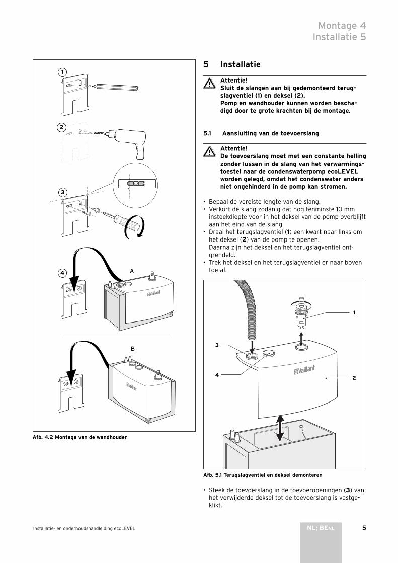
5Installatie- en onderhoudshandleiding ecoLEVEL NL; BENL
A
B
Afb. 4.2 Montage van de wandhouder
5 Installatie
Attentie!Sluit de slangen aan bij gedemonteerd terug-slagventiel (1) en deksel (2).Pomp en wandhouder kunnen worden bescha-digd door te grote krachten bij de montage.
5.1 Aansluiting van de toevoerslang
Attentie!De toevoerslang moet met een constante helling zonder lussen in de slang van het verwarmings-toestel naar de condenswaterpomp ecoLEVEL worden gelegd, omdat het condenswater anders niet ongehinderd in de pomp kan stromen.
• Bepaal de vereiste lengte van de slang.• Verkort de slang zodanig dat nog tenminste 10 mm
insteekdiepte voor in het deksel van de pomp overblijft aan het eind van de slang.
• Draai het terugslagventiel (1) een kwart naar links om het deksel (2) van de pomp te openen.Daarna zijn het deksel en het terugslagventiel ont-grendeld.
• Trek het deksel en het terugslagventiel er naar boven toe af.
1
3
4 2
Afb. 5.1 Terugslagventiel en deksel demonteren
• Steek de toevoerslang in de toevoeropeningen (3) van het verwijderde deksel tot de toevoerslang is vastge-klikt.
Montage 4Installatie 5
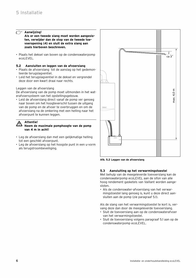
6 Installatie- en onderhoudshandleiding ecoLEVEL
Aanwijzing!Als er een tweede slang moet worden aangeslo-ten, verwijder dan de stop van de tweede toe-voeropening (4) en sluit de extra slang aan zoals hierboven beschreven.
• Plaats het deksel van boven op de condenswaterpomp ecoLEVEL.
5.2 Aansluiten en leggen van de afvoerslang• Plaats de afvoerslang tot de aanslag op het gedemon-
teerde terugslagventiel.• Leid het terugslagventiel in de deksel en vergrendel
deze door een kwart draai naar rechts.
Leggen van de afvoerslangDe afvoerslang van de pomp moet uitmonden in het wat-erafvoersysteem van het opstellingsgebouw.• Leid de afvoerslang direct vanaf de pomp ver genoeg
naar boven om het hoogteverschil tussen de uitgang van de pomp en de afvoer te overbruggen en om de afvoerslang na de omkering met een helling naar het afvoerpunt te kunnen leggen.
Attentie!Neem de maximale pomphoogte van de pomp van 4 m in acht!
• Leg de afvoerslang dan met een gelijkmatige helling tot een geschikt afvoerpunt.
• Leg de afvoerslang op het hoogste punt in een u-vorm als terugstroombeveiliging.
m
ax. 4
,0 m
ca 3˚
Afb. 5.2 Leggen van de afvoerslang
5.3 Aansluiting op het verwarmingstoestelMet behulp van de meegeleverde toevoerslang kan de condenswaterpomp ecoLEVEL aan de sifon van alle hoog rendement gasketels van Vaillant worden aange-sloten.• Als de condenswater-afvoerslang van het verwar-
mingstoestel lang genoeg is, kunt u deze direct aan-sluiten aan de pomp (zie paragraaf 5.1).
Als de slang van het verwarmingstoestel te kort is, ver-vang deze dan door de meegeleverde toevoerslang.• Sluit de toevoerslang aan op de condenswaterafvoer
van het verwarmingstoestel.• Sluit de toevoerslang volgens paragraaf 5.1 aan op de
condenswaterpomp ecoLEVEL.
5 Installatie

7Installatie- en onderhoudshandleiding ecoLEVEL NL; BENL
6 Elektrische aansluiting
6.1 AlgemeenNadat de condenswaterpomp ecoLEVEL is gemonteerd kunt u beginnen met de elektrische aansluiting van het toestel.De voedingsspanning van de pomp vindt plaats via de kabel (1) met het vrije kabeleinde.De overloop-veiligheidsschakelaar wordt met de kabel (2) aangesloten op het verwarmingstoestel.De elektrische aansluiting mag enkel door een erkende installateur uitgevoerd worden.
Gevaar!Levensgevaar door elektrocutie. Bij een ondes-kundige installatie bestaat er gevaar voor elek-trocutie en beschadiging van het toestel.
De pomp en het verwarmingstoestel moeten voor de elektrische aansluiting spanningsvrij worden geschakeld en tegen herinschakelen worden beveiligd.
Aanwijzing!Alle elektrische en condenswatervoerende ver-bindingen naar de pomp moeten spanningsvrij worden gelegd.
1
2
Afb. 6.1 Overzicht van de elektrische aansluitingen
Legenda1 Aansluitkabel 230 V (indien nodig: stekker aansluitbaar)2 Aansluitkabel van de overloop-veiligheidsschakelaar
6.2 Aansluiting van de 230 V netspanningDe 230 V netspanning kan naar keuze op twee manieren worden aangesloten:• sluit de leiding (1) aan op 230 V netspanning via de
netspanningsuitgang van het verwarmingstoestelof• monteer een netstekker aan de kabel (1) en sluit de
pomp aan via een netcontactdoos (de stekker is niet bij de levering inbegrepen).
6.3 Aansluiting van de overloop-veiligheidsschakelaar
De wijze van aansluiting op de platine is afhankelijk van het verwarmingstoestel.In de tabel vindt u de wijze van aansluiting voor het betreffende verwarmingstoestel.
Land VerwarmingstoestelAansluiting van de over-loop-veiligheidsschakelaar
BE ecoTEC plus Aansluitwijze B
BE ecoTEC pro Aansluitwijze B
BE ecoMAX exclusiv Aansluitwijze A
BE ecoMAX Aansluitwijze A
BE ecoVIT Aansluitwijze A
BE ecoCOMPACT Aansluitwijze A
NL hrEXCLUSIEF Aansluitwijze A
NL hrSOLIDE Aansluitwijze B
NL hrPRO Aansluitwijze B
Tabel 6.1 Aansluitwijzen voor verschillende verwarmings-
toestellen
De beschrijving van de betreffende aansluitwijze vindt u in de volgende paragrafen.
Elektrische aansluiting 6

8 Installatie- en onderhoudshandleiding ecoLEVEL
Aansluitwijze ASluit de overloop-veiligheidsschakelaar als volgt aan op het laagspanningscircuit van het verwarmingstoestel:• open de schakelkast van het verwarmingstoestel• verwijder de kabelbrug op de platine van het verwar-
mingstoestel op de blauwe aansluitplaats „Anl-Therm" • plaats op deze aansluitplaats de kabel met de blauwe
Pro E-stekker van de condenswaterpomp ecoLEVEL.
98
75
43
NL
NL
Pu
mp
e 2
. Pu
mp
eA
nl -
Th
erm
L N
24
V I
23
0V
RT
24
V2
30
VR
T 2
30
V
X 10
X 7
X 8
X 2
13
11
1
1
Co
die
rwid
erstan
d
1
2
Afb. 6.2 Aansluiting van de overloop-veiligheidsschakelaar, aan-
sluitwijze A
6 Elektrische aansluiting

9Installatie- en onderhoudshandleiding ecoLEVEL NL; BENL
Elektrische aansluiting 6
Aansluitwijze BSluit de overloop-veiligheidsschakelaar op de volgende manier aan op het laagspanningscircuit van het verwar-mingstoestel:• open de schakelkast van het verwarmingstoestel• plaats de passende stekker op rand-aansluitplaats X40
1
Afb. 6.3 Aansluiting van de overloop-veiligheidsschakelaar, aan-
sluitwijze B
Aanwijzing!Als in het cv-toestel een multifunctionele module 2 van 7 (art.-nr. 00 2001 7744) is gemonteerd, dan is de aansluiting X40 al in gebruik. In dit geval wordt de stekker aangeslo-ten op aansluiting X40B van de multifunctione-le module 2 van 7.Zie hiervoor ook de handleiding van de multi-functionele module.

10 Installatie- en onderhoudshandleiding ecoLEVEL
7 Inbedrijfname
Nadat de condenswaterpomp ecoLEVEL mechanisch en elektrisch is geïnstalleerd is deze bedrijfsklaar. De groe-ne LED brandt.
Aanwijzing!Na de installatie en inbedrijfname werkt de pomp automatisch en hoeft niet verder te wor-den bediend.
7.1 Weergave van de bedrijfsstatusAan de voorkant van de behuizing zijn twee dioden geïn-tegreerd, die de bedrijfsstatus weergeven van de con-denswaterpomp.De volgende statusindicaties worden door de groene LED gesignaleerd:
LED groen LED rood Betekenis
Brandt UitPomp wordt voorzien van 230 V netspanning
Knippert Uit Pomp is in bedrijf en pompt condensaat.
Als de rode LED knippert of brandt is er een storing. Zie hoofdstuk 9.
8 Onderhoud
Gevaarlijk!Levensgevaar door elektrocutie aan spannings-voerende aansluitingen. Schakel altijd eerst de stroomtoevoer naar de pomp en naar het ver-warmingstoestel uit. Pas daarna mag u de het onderhoud uitvoeren.
• Zorg ervoor dat de toe- en afvoer vrij is.• Verwijder het pompdeksel en controleer het conden-
saat-reservoir op vervuiling. Reinig indien nodig het condensaat-reservoir met warm water en een milde reiniger.
• Demonteer het terugslagventiel en reinig deze door te spoelen met een waterstraal.
• Controleer de toe- en afvoerleidingen en reinig deze indien nodig.
• Zorg ervoor dat de leidingen niet geknikt zijn om een ongehinderde doorstroom te garanderen.
Aanwijzing!Het onderhoud van de pomp kan worden meege-nomen bij de onderhoudsintervallen van het verwarmingstoestel. De pomp moet tenminste een keer per jaar een onderhoudsbeurt krijgen.
9 Diagnose en verhelpen van storingen
9.1 StoringenDe condenswaterpomp ecoLEVEL kan korte storingen in de normale werking automatisch verhelpen. De volgende situaties worden door de groene LED gesignaleerd:
LED groen LED rood Betekenis
Knippert BrandtHet maximaal toegestane waterpeil in de pomp is overschreden.De boiler wordt leeggepompt.
Knippert KnippertDe pomp bevindt zich voor een vastgestelde tijd in de ruststand en gaat automatisch weer in bedrijf.
Als de rode LED brandt of knippert, dan heeft de water-stand de maximaal toegestane waarde overschreden en is de overloop-veiligheidsschakelaar geactiveerd. Er wordt een potentiaalvrij contact resp. het elektriciteits-circuit geopend om het verwarmingstoestel uit te scha-kelen.Als er een verbinding met het verwarmingstoestel is geïnstalleerd wordt het verwarmingstoestel uitgescha-keld om het ontstaan van meer condenswater te voorko-men.
9.2 StoringsdiagnoseAls de rode LED voor een langere tijd knippert of brandt, is er een storing opgetreden in de installatie of is de pomp defect. Controleer voor het verhelpen van de sto-ring de volgende punten.
Oorzaak Verhelpen van storingen
Pomp pompt niet:afvoerslang geknikt
Knik verwijderen
Motor blokkeert
Visuele controle van de motortoevoer: controleren op vreemde voorwerpen en evt. vreemde voorwerpen verwijderen
Motor defect Condenswaterpomp vervangen
Pomp wordt niet gevuld
Toevoerslangen controleren op ligging, verstopping en aansluiting aan de pomp, indien nodig fout verhelpen
Vlotter blokkeert Vlotter vrijmaken
7 Inbedrijfname8 Onderhoud9 Diagnose en verhelpen van storingen

11Installatie- en onderhoudshandleiding ecoLEVEL NL; BENL
Servicedienst 10Technische gegevens 11
10 Servicedienst
Servicedienst (België)Vaillant sa-nvGolden Hopestraat 151620 DrogenbosTel : 02 334 93 52
Servicedienst (Nederland)De servicedienst is er ter ondersteuning van de installa-teur en tijdens kantooruren te bereiken op nummer (020) 565 92 00.
11 Technische gegevens
Technische gegevens Units ecoLEVEL
Bouwvorm Toestel voor wandmontage
Nominale inhoud l 0,5
Netspanning V 230
Max. stroom A 1
Frequentie Hz 50
Max. nominaal vermogen W 22
Max. pomphoogte m 4
Pompvolume l/h 150
Afmetingen Hoogte mm 160
Breedte mm 180
Diepte mm 100
Gewicht met watervulling kg 1,8
Toevoerslang (max. buitendiameter) mm 24
Afvoerslang (min. binnendiameter) mm 10
Watertoevoertemperatuur °C 1 ... 60
Omgevingstemperatuur °C 5 ... 60
Veiligheid storing-immuniteit voor IR en netvoeding
Overloop-veiligheidsschakelaar 5 mA ...4 A; 230 V
Beschermingsklasse volgens EN 60529 IP 44
Tabel 11.1 Technische gegevens


1Istruzioni per l‘uso per ecoLEVEL IT; CHIT
Indice
1 Avvertenze sulla documentazione . . . . . . . . . . 21.1 Conservazione della documentazione . . . . . . . . . 21.2 Simboli impiegati . . . . . . . . . . . . . . . . . . . . . . . . . . . 2
2 Avvertenze per la sicurezza e norme . . . . . . . 2
3 Avvertenze per l‘uso . . . . . . . . . . . . . . . . . . . . . 33.1 Garanzia e responsabilità . . . . . . . . . . . . . . . . . . . . 33.2 Impiego conforme alla destinazione . . . . . . . . . . . 33.3 Cura . . . . . . . . . . . . . . . . . . . . . . . . . . . . . . . . . . . . . . 33.4 Riciclaggio e smaltimento . . . . . . . . . . . . . . . . . . . 3
4 Uso e manutenzione . . . . . . . . . . . . . . . . . . . . . 34.1 Informazioni generali . . . . . . . . . . . . . . . . . . . . 34.2 Indicazione dello stato di funzionamento . . . . . . 34.3 Manutenzione . . . . . . . . . . . . . . . . . . . . . . . . . . . . . . 4
Per l‘utente
Istruzioni per l’uso
ecoLEVEL
Pompa per lo scarico della condensa

2 Istruzioni per l‘uso per ecoLEVEL
1 Avvertenze sulla documentazione
Le seguenti avvertenze sono indicative per tutta la docu-mentazione.Consultare anche le altre documentazioni valide in com-binazione con queste istruzioni per l‘uso, l‘installazione e la manutenzione.Non ci assumiamo alcuna responsabilità per danni insorti a causa della mancata osservanza di queste istruzioni.
Documentazione integrativaPer l‘uso della pompa per lo scarico della condensa ecoLEVEL si prega di osservare tutte le istruzioni per l‘uso delle parti costruttive e dei componenti dell‘impian-to. Queste istruzioni per l‘uso sono in dotazione con le parti costruttive dell‘impianto e con i componenti di volta in volta integrati.
1.1 Conservazione della documentazioneCustodire il manuale di istruzioni per l‘uso, l‘installazione e la manutenzione con tutta la documentazione integra-tiva in un luogo facilmente accessibile, perché sia sem-pre a portata di mano per ogni evenienza. In caso di cambio di utente, consegnare la documenta-zione al proprietario successivo.
1.2 Simboli impiegatiPer l‘uso si prega di osservare le avvertenze per la sicu-rezza contenute in queste istruzioni per l‘uso!
Pericolo!Pericolo di morte per scarica elettrica.
Pericolo!Immediato pericolo di morte.
Attenzione!Possibili situazioni di pericolo per il prodotto e per l‘ambiente.
Avvertenza!Informazioni e avvertenze utili.
• Simbolo per un intervento necessario
2 Avvertenze per la sicurezza e norme
Eventuali modifiche alla pompa per lo scarico della con-densa ecoLEVEL sono in linea generale vietate. Per modifiche alle parti dell‘apparecchio incaricare un tecni-co abilitato e qualificato.
Attenzione!Pericolo di danneggiamento a causa di modifi-che non a regola d‘arte!Non effettuare mai interventi o modifiche alla pompa o ad altre parti dell‘impianto.
Installazione, messa in servizio e funzionamento
Pericolo!Pericolo dovuto a tensioni che possono provoca-re la morte.Nell‘apparecchio e sulle linee di alimentazione sono presenti tensioni che possono provocare la morte. Pertanto l‘apparecchio deve essere installato oppure aperto esclusivamente da un tecnico abilitato.
Questi si assume anche la responsabilità dell‘installazio-ne e la messa in servizio conformi alle vigenti norme. Egli è anche responsabile dell‘ispezione/manutenzione della pompa per lo scarico della condensa ecoLEVEL.- Non utilizzare la pompa per rimuovere liquidi infiam-
mabili ed esplosivi quali: benzina, olio combustibile ecc. Può sussistere il pericolo di ustioni ed esplosioni.
- Non utilizzare la pompa in un‘atmosfera esplosiva poi-ché durante l‘uso della pompa potrebbe verificarsi un‘esplosione.
CondensaIl contatto con la condensa convogliata dalla pompa può rappresentare un pericolo per gli occhi. Assicurarsi che la pompa per lo scarico della condensa ecoLEVEL venga messa in funzione fuori dalla portata dei bambini.
1 Avvertenze sulla documentazione2 Indicazioni sulla sicurezza e norme

3Istruzioni per l‘uso per ecoLEVEL IT; CHIT
Avvertenze per l‘uso 3Uso e manutenzione 4
3 Avvertenze per l‘uso
3.1 Garanzia e responsabilitàLa garanzia del costruttore ha valore solo se l‘installa-zione è stata effettuata da un tecnico abilitato e qualifi-cato ai sensi della legge. L‘acquirente dell‘apparecchio può avvalersi di una garanzia di fabbrica di 2 anni. I lavo-ri coperti da garanzia vengono effettuati, di regola, uni-camente dal nostro servizio di assistenza. I costi per lavori sull‘apparecchio effettuati nel periodo di validità della garanzia verranno rimborsati solo se è stato stipulato un contratto corrispondente e se il tipo di intervento è contemplato dalla garanzia.
3.2 Impiego conforme alla destinazioneLa pompa per lo scarico della condensa ecoLEVEL può essere utilizzata esclusivamente in combinazione con i componenti di sistema Vaillant nei quali, in seguito all‘esercizio, viene a formarsi condensa come sottopro-dotto. In questa categoria rientrano tutte le caldaie a basamento Vaillant. La pompa e i suoi componenti sono stati ideati per tra-sportare la condensa dagli impianti di riscaldamento. Questo modello è già corredato di sistema di scarico fumi dell‘acqua piovana. Questo si riferisce sia alla quan-tità ammessa che alla composizione e ai componenti dei corpi solidi presenti nella condensa.La pompa per lo scarico della condensa non è adatta per convogliare altri prodotti liquidi o solidi. Soprattutto sca-richi di qualsiasi tipo, prodotti chimici o emulsioni oleose non devono essere convogliati nella pompa per la con-densa. Qualsiasi altro utilizzo diverso da quello descritto in que-sta sede, soprattutto il trasporto di prodotti non autoriz-zati, è da considerarsi non conforme. Il produttore/forni-tore non si assume la responsabilità per danni causati da uso improprio. La responsabilità ricade unicamente sul-l‘utilizzatore.Un impiego conforme alla destinazione comprende anche l’osservanza delle rispettive istruzioni per l‘uso, l‘installazione e la manutenzione.
Attenzione!Ogni altro scopo è da considerarsi improprio e quindi non ammesso.
3.3 CuraPulire la superficie con un panno umido. Non utilizzare detergenti corrosivi!
3.4 Riciclaggio e smaltimentoLa pompa e l‘imballo sono costituiti principalmente da materiali riciclabili.
ApparecchioLa pompa difettosa e tutti i suoi accessori devono essere smaltiti adeguatamente. Provvedere a smaltire l‘appa-
recchio vecchio e gli accessori differenziandoli opportu-namente.
ImballoDelegare lo smaltimento dell‘imballo usato per il traspor-to dell‘apparecchio all'azienda qualificata, responsabile dell'installazione.
4 Uso e manutenzione
4.1 Informazioni generaliLa pompa per lo scarico della condensa ecoLEVEL viene impiegata per rimuovere la condensa presente in impian-ti di riscaldamento a combustione. La condensa presente nell‘impianto di riscaldamento viene convogliata, mediante un tubo di drenaggio, nel serbatoio della pompa.Grazie ad una misurazione costante del livello dell‘acqua, una volta raggiunto il livello di riempimento massimo, la pompa viene attivata automaticamente svuotando così, mediante un flessibile di travaso, la condensa.La pompa per lo scarico della condensa ecoLEVEL dispo-ne di un interruttore di sicurezza per troppopieno. Per impedire in caso di disturbo che la condensa fuoriesca, questo interruttore spegne in modo automatico l‘appa-recchio di riscaldamento, se provvisto di raccordo corri-spondente.
Avvertenza!Eseguita l‘installazione e la messa in funzione della pompa il funzionamento viene regolato automaticamente e non necessita di un coman-do ulteriore.
4.2 Indicazione dello stato di funzionamentoNel bordo anteriore dell‘alloggiamento sono integrati due diodi che indicano lo stato di funzionamento della pompa per lo scarico della condensa ecoLEVEL.Se la pompa viene alimentata con una tensione di rete di 230 V, il LED verde è acceso. Questo significa che la pompa è pronta per il funzionamento.Il LED rosso indica che il livello dell‘acqua ha superato il valore massimo ammesso e che l‘interruttore di sicurez-za per troppopieno è stato attivato.A condizione che sia stato installato un collegamento per tale scopo, l‘apparecchio di riscaldamento viene spento, per impedire la formazione di ulteriore conden-sa.
Avvertenza!Se il LED rosso lampeggia o rimane acceso per un lungo intervallo di tempo, significa che è pre-sente un errore di installazione o un guasto nella pompa.Richiedere l‘intervento di un tecnico abilitato per il controllo e la riparazione della pompa.
4 Istruzioni per l‘uso per ecoLEVEL
4.3 ManutenzioneFare controllare e pulire la pompa per lo scarico della condensa ecoLEVEL almeno ogni 2 anni da un tecnico abilitato.
4 Uso e manutenzione

1Istruzioni per l‘installazione e la manutenzione di ecoLEVEL IT; CHIT
Indice
1 Avvertenze sulla documentazione . . . . . . . . . . 21.1 Collocazione e conservazione della
documentazione . . . . . . . . . . . . . . . . . . . . . . . . . . . . 21.2 Simboli impiegati . . . . . . . . . . . . . . . . . . . . . . . . . . . 21.3 Marcatura CE . . . . . . . . . . . . . . . . . . . . . . . . . . . . . . 21.4 Targhetta . . . . . . . . . . . . . . . . . . . . . . . . . . . . . . . . . . 2
2 Avvertenze per la sicurezza e norme . . . . . . . 2
3 Avvertenze per l‘installazione e il funzionamento . . . . . . . . . . . . . . . . . . . . . . . . . . 3
3.1 Garanzia e responsabilità . . . . . . . . . . . . . . . . . . . . 33.2 Impiego conforme alla destinazione . . . . . . . . . . . 33.3 Riciclaggio e smaltimento . . . . . . . . . . . . . . . . . . . 4
4 Montaggio . . . . . . . . . . . . . . . . . . . . . . . . . . . . . 44.1 Fornitura . . . . . . . . . . . . . . . . . . . . . . . . . . . . . . . . . . 44.2 Scelta del luogo di montaggio . . . . . . . . . . . . . . . . 44.3 Dimensioni e spazi liberi per il montaggio . . . . . 44.4 Montaggio per il supporto a muro . . . . . . . . . . . . 4
5 Installazione . . . . . . . . . . . . . . . . . . . . . . . . . . . 55.1 Collegamento del tubo di drenaggio . . . . . . . . . . 5
5.2 Collegamento e posa del flessibile di travaso . . . 65.3 Allacciamento all‘apparecchio di riscaldamento 6
6 Allacciamento elettrico . . . . . . . . . . . . . . . . . . 76.1 Generalità . . . . . . . . . . . . . . . . . . . . . . . . . . . . . . . . . 76.2 Collegamento della tensione di rete di 230 V . . . 76.3 Collegamento dell‘interruttore di sicurezza per
troppopieno . . . . . . . . . . . . . . . . . . . . . . . . . . . . . . . . 7
7 Messa in servizio . . . . . . . . . . . . . . . . . . . . . . . . 107.1 Indicazione dello stato di funzionamento . . . . . . 10
8 Manutenzione . . . . . . . . . . . . . . . . . . . . . . . . . . 10
9 Diagnosi ed eliminazione dei disturbi . . . . . . . 109.1 Disturbi . . . . . . . . . . . . . . . . . . . . . . . . . . . . . . . . . . . . 109.2 Diagnosi degli errori . . . . . . . . . . . . . . . . . . . . . . . . 10
10 Servizio di assistenza clienti . . . . . . . . . . . . . . 11
11 Dati tecnici . . . . . . . . . . . . . . . . . . . . . . . . . . . . 11
Per il tecnico abilitato
Istruzioni per l‘installazione e la manutenzione
ecoLEVEL
Pompa per lo scarico della condensa

2 Istruzioni per l‘installazione e la manutenzione di ecoLEVEL
1 Avvertenze sulla documentazione
Le seguenti avvertenze sono indicative per tutta la docu-mentazione.Consultare anche le altre documentazioni valide in com-binazione con queste istruzioni per l‘uso, l‘installazione e la manutenzione.Non ci assumiamo alcuna responsabilità per danni insorti a causa della mancata osservanza di queste istruzioni.
Documentazione integrativaPer l‘installazione della pompa per lo scarico della con-densa si prega di osservare le istruzioni per il montaggio e l‘installazione delle parti costruttive e dei componenti della stessa. Queste istruzioni sono in dotazione con le parti costruttive dell‘impianto e con i componenti di volta in volta integrati.
1.1 Collocazione e conservazione della documentazione
Consegnare queste istruzioni per l‘uso, l‘installazione e la manutenzione all‘utente dell‘impianto. Egli si assume la responsabilità per la conservazione delle istruzioni in modo da poterle utilizzare in caso di necessità.
1.2 Simboli impiegatiDurante l‘installazione e la manutenzione della pompa per lo scarico della condensa, osservare le avvertenze per la sicurezza contenute in questo manuale.
Pericolo!Pericolo di morte per scarica elettrica.
Pericolo!Immediato pericolo di morte.
Attenzione!Possibili situazioni di pericolo per il prodotto e per l‘ambiente.
Avvertenza!Informazioni e avvertenze utili.
• Simbolo per un intervento necessario
1.3 Marcatura CECon la marcatura CE viene certificato che la pompa per lo scarico della condensa ecoLEVEL, con i dati riportati sulla targhetta, soddisfa i requisiti fondamentali delle direttive in vigore riportate qui di seguito.- Tensioni ammesse (direttive EN 60 335-1 e EN 60 335-2-41)- Compatibilità elettromagnetica (direttive EN 55 014-1 e
EN 55 014-2)
1.4 TarghettaLa targhetta con il numero seriale, la classe di protezio-ne, la tensione di alimentazione, la frequenza e la marca-
tura CE si trovano sul lato inferiore della pompa per lo scarico della condensa ecoLEVEL.
2 Avvertenze per la sicurezza e norme
Attenzione!Pericolo dovuto a tensioni che possono provoca-re la morte.Nell‘apparecchio e sulle linee di alimentazione sono presenti tensioni che possono provocare la morte. Pertanto l‘apparecchio deve essere installato e aperto esclusivamente da un tecni-co abilitato.
Norme e direttiveIEC 60364-7-712 Electrical installations of buildings - Part 7-712Metodi di prova per la compatibilità elettronica confor-memente a EN 50081-1:1992,EN 50082-1:1997 Emissione di disturbi: EN 55014-1 1993 Immunità ai disturbi: EN 55014-2 1997
Norme tecnicheIl montaggio deve avvenire in conformità delle condizio-ni del luogo, delle norme locali e delle norme tecniche.
Norme antinfortunisticheLa pompa per lo scarico della condensa deve essere installata ad opera di un‘azienda specializzata ricono-sciuta che è responsabile del rispetto delle norme e delle direttive in vigore.Condizione essenziale per il funzionamento corretto e sicuro di questo apparecchio sono: un trasporto appro-priato, uno stoccaggio, installazione e montaggio ade-guati nonché una manutenzione e un uso corretti.
Solo i tecnici abilitati che hanno acquisito col tempo familiarità con tutte le indicazioni di sicurezza, nonché con le indicazioni di montaggio, funzionamento e manu-tenzione contenute in queste istruzioni per l‘uso e l‘in-stallazione possono operare con questo apparecchio.Durante il funzionamento di questo apparecchio deter-minati componenti sono inevitabilmente soggetti ad una tensione pericolosa che può causare gravi ferite o addi-rittura la morte.Per minimizzare il pericolo legato all‘incolumità fisica, osservare le seguenti misure di sicurezza.1. Il montaggio dell‘apparecchio deve essere effettuato in
conformità alle disposizioni di sicurezza, nonché a tutte le altre norme statali o locali rilevanti. Per garan-tire la sicurezza di esercizio è necessario provvedere ad una messa a terra corretta, ad un dimensionamento dei conduttori e ad una corrispondente protezione da corto circuito.
2. L‘apertura del coperchio del fondo è consentita solo a personale specializzato.
1 Avvertenze sulla documentazione2 Avvertenze per la sicurezza e norme
3Istruzioni per l‘installazione e la manutenzione di ecoLEVEL IT; CHIT
Il coperchio del fondo deve essere aperto solo quando tutti i collegamenti elettrici sono staccati dalla pompa.
3. Prima di effettuare controlli visivi e lavori di manuten-zione assicurarsi che l‘alimentazione di corrente sia spenta e che non possa essere reinserita accidental-mente. Qualora debbano essere effettuate misurazioni con alimentazione di corrente inserita, non toccare in nessun caso i punti di collegamento elettrici. Non indossare gioielli alle dita e ai polsi. Assicurarsi che i mezzi utilizzati per la verifica siano in buone condizio-ni di esercizio.
4. Effettuare i lavori con apparecchio acceso, operando su una base isolata, assicurarsi in pratica che non vi sia una messa a terra.
5. Seguire scrupolosamente le istruzioni per l‘uso, l‘in-stallazione e la manutenzione contenute in questo manuale e osservare tutte le indicazioni di pericolo, avvertimento e cautela.
6. Questa lista non rappresenta un elenco completo di tutte le misure necessarie per il funzionamento sicuro dell‘apparecchio. Qualora dovessero presentarsi pro-blemi speciali che per gli scopi del compratore non sono stati trattati in modo sufficientemente esaurien-te, rivolgersi al rivenditore specializzato di riferimento.
Avvertenze per la sicurezza- Non utilizzare la pompa per rimuovere liquidi infiam-
mabili ed esplosivi quali: benzina, olio combustibile ecc. Può sussistere il pericolo di ustioni ed esplosioni.
- Non utilizzare la pompa in un‘atmosfera esplosiva poi-ché durante l‘uso della pompa potrebbe verificarsi un‘esplosione.
- Il raccordo della pompa dispone di un conduttore di terra.Assicurarsi che l‘alimentazione di corrente sia messa a terra in conformità delle disposizioni di legge.
- Per impedire una fuoriuscita di condensa o danni all‘apparecchio di riscaldamento dovuti ad un guasto della pompa, collegare all‘interruttore di sicurezza, un interruttore di corrente o un allarme.
- Assicurarsi che la pompa lavori in condizioni sicure o che sia fissata alla parete altrimenti potrebbero insor-gere dei disturbi di funzionamento alla pompa che potrebbero causare danni alla pompa o all‘apparecchio di riscaldamento.
- Non collegare il flessibile di travaso per la condensa della pompa direttamente al tubo di scarico.Pericolo di intossicazione per fughe di gas combusti! Il sifone interno dell‘apparecchio di riscaldamento potrebbe venire prosciugato.
- Se l‘installazione dovesse richiedere un tubo di scarico per la condensa più lungo, impiegare solo tubi di scari-co omologati secondo DIN 1986-4. Nel caso di utilizzo di tubi di scarico non adatti possono crearsi perdite e danni dovuti alla fuoriuscita di condensa.
Modifiche
Eventuali modifiche alla pompa sono in linea generale vietate. Sono ammesse modifiche alle parti dell‘apparec-chio purché conformi alle norme nazionali.
Attenzione!Pericolo di danneggiamento a causa di modifi-che non a regola d‘arte!Non effettuare mai interventi o modifiche alla pompa o ad altre parti dell‘impianto.
3 Avvertenze per l‘installazione e il funzionamento
3.1 Garanzia e responsabilitàLa garanzia del costruttore ha valore solo se l‘installa-zione è stata effettuata da un tecnico abilitato e qualifi-cato ai sensi della legge. L‘acquirente dell‘apparecchio può avvalersi di una garanzia di fabbrica di 2 anni. I lavo-ri coperti da garanzia vengono effettuati, di regola, uni-camente dal nostro servizio di assistenza. I costi per lavori sull‘apparecchio effettuati nel periodo di validità della garanzia verranno rimborsati solo se è stato stipulato un contratto corrispondente e se il tipo di intervento è contemplato dalla garanzia.
3.2 Impiego conforme alla destinazioneQuesta pompa per lo scarico della condensa può essere utilizzata esclusivamente in combinazione con i compo-nenti di sistema Vaillant nei quali, in seguito all‘esercizio, viene a formarsi condensa come sottoprodotto. In que-sta categoria rientrano tutte le caldaie a basamento Vaillant. La pompa per la condensa e i suoi componenti sono stati ideati per scaricare la condensa dagli impianti di riscaldamento. Questo modello è già corredato di siste-ma di scarico fumi dell‘acqua piovana. Questo si riferisce sia alla quantità ammessa che alla composizione e ai componenti dei corpi solidi presenti nella condensa.La pompa per la condensa non è adatta per convogliare altri prodotti liquidi o solidi. Soprattutto scarichi di qual-siasi tipo, prodotti chimici o emulsioni oleose non devo-no essere convogliati nella pompa per la condensa. Qualsiasi altro utilizzo diverso da quello descritto in que-sta sede, soprattutto il trasporto di prodotti non autoriz-zati, è da considerarsi non conforme. Il produttore/forni-tore non si assume la responsabilità per danni causati da uso improprio. La responsabilità ricade unicamente sul-l‘utilizzatore.Un impiego conforme alla destinazione comprende anche l’osservanza delle rispettive istruzioni per l‘instal-lazione e la manutenzione.
Attenzione!Ogni altro scopo è da considerarsi improprio e quindi non ammesso.
Avvertenze per la sicurezza e norme 2Avvertenze per l‘installazione e il funzionamento 3

4 Istruzioni per l‘installazione e la manutenzione di ecoLEVEL
3.3 Riciclaggio e smaltimentoLa pompa e l‘imballo sono costituiti principalmente da materiali riciclabili.
ApparecchioLa pompa difettosa e tutti i suoi accessori devono essere smaltiti adeguatamente. Provvedere a smaltire l‘appa-recchio vecchio e gli accessori differenziandoli opportu-namente.
ImballoDelegare lo smaltimento dell‘imballo usato per il traspor-to dell‘apparecchio all'azienda qualificata, responsabile dell'installazione.
4 Montaggio
4.1 Fornitura
Denominazione Dimensioni Quantità
Pompa per lo scarico della condensa
180 x 160 x 100 mm 1
Dadi per il montaggio 5 mm 2
Viti 4 x 35 mm 2
Tubo di drenaggio Ø 24 mm x 1,15 m 1
Flessibile di travaso Ø 10 mm x 6 m 1
Supporto a parete - 1
Supporto a muro per flessibile di travaso
- 6
Istruzioni l‘uso, l‘installazione e la manutenzione
- 1
Tab. 4.1 Dotazione alla consegna
Per il montaggio sono necessari i seguenti utensili:- trapano- punta da trapano (5 mm)- cacciavite ad intaglio- livella ad acqua- tagliente- utensili per l‘allacciamento elettrico
4.2 Scelta del luogo di montaggioLa pompa per lo scarico della condensa ecoLEVEL è pre-vista per l‘installazione nel relativo locale dell‘apparec-chio di riscaldamento. La temperatura ambiente deve essere compresa fra 5 °C e 60 °C.Il locale previsto per l‘installazione deve disporre di una parete che permetta di utilizzare gli elementi di raccordo in dotazione. Qualora non fosse possibile, occorre creare una superficie di montaggio corrispondente. La pompa per lo scarico della condensa ecoLEVEL non deve servire come ripiano per oggetti.
4.3 Dimensioni e spazi liberi per il montaggio
100 mm
90 mm
165 mm
115
mm
150
mm
175 mm
min
. 20
0 m
m
min. 5 mm min. 5 mm
min
. 20
0 m
m
min. 5 mm min. 5 mm
Fig. 4.1 Dimensioni e spazi liberi per il montaggio
4.4 Montaggio per il supporto a muro• Estrarre verso il basso il supporto a muro premontato
dall‘alloggiamento della pompa per lo scarico della condensa.
• Montare il supporto a parete come da fig. 4.2 nel punto previsto al di sotto dello scarico della condensa dell‘apparecchio di riscaldamento.Il supporto a muro deve essere montato orizzontal-mente. Impiegare una livella ad acqua.
• Spingere la pompa per la condensa dall‘alto in modo diritto sugli spigoli della guida del supporto a muro.Nella posizione più in basso un piccolo gancio blocca la pompa al supporto a muro.
Avvertenza!La pompa per lo scarico della condensa può essere fissata sia sul lato stretto che sul lato posteriore largo del supporto come illustrato nella fig. 4.1.
3 Avvertenze per l‘installazione e il funzionamento4 Montaggio

5Istruzioni per l‘installazione e la manutenzione di ecoLEVEL IT; CHIT
A
B
Fig. 4.2 Montaggio del supporto a muro
5 Installazione
Attenzione!Collegare i tubi flessibili quando la valvola di non ritorno (1) e il coperchio (2) sono smontati.La pompa e il supporto a parete possono essere danneggiati se sottoposti ad una forza consi-stente.
5.1 Collegamento del tubo di drenaggio
Attenzione!Il tubo di drenaggio deve essere posato con una pendenza costante e senza nodi nel tubo flessi-bile fra l'apparecchio di riscaldamento e la pompe per lo scarico della condensa ecoLEVEL, poiché altrimenti la condensa non può scorrere liberamente nella pompa.
• Determinare la lunghezza necessaria del flessibile.• Ridurre il tubo flessibile in modo che rimangano alme-
no 10 mm di profondità di inserimento nel coperchio della pompa sull‘estremità del tubo, sbloccando così sia il coperchio che la valvola di non ritorno.
• Per aprire il coperchio (2) della pompa, ruotare la val-vola di non ritorno (1) di un quarto di giro verso sini-stra.
• Rimuovere il coperchio e la valvola di non ritorno verso l‘alto.
1
3
4 2
Fig. 5.1 Smontaggio della valvola di non ritorno e del coperchio
Montaggio 4Installazione 5

6 Istruzioni per l‘installazione e la manutenzione di ecoLEVEL
• Inserire il tubo di drenaggio nella rispettiva apertura (3) del coperchio rimosso finché il tubo di drenaggio non si innesta.
Avvertenza!Nel caso in cui sia collegato un secondo tubo flessibile, rimuovere il tappo dalla seconda aper-tura di drenaggio (4) e collegare il tubo flessibi-le supplementare come descritto sopra.
• Applicare il coperchio dall‘alto sulla pompa per la con-densa ecoLEVEL.
5.2 Collegamento e posa del flessibile di travaso• Inserire il flessibile di travaso fino all‘arresto sulla val-
vola di non ritorno smontata.• Inserire la valvola di non ritorno nel coperchio e bloc-
carla con un quarto di giro verso destra.
Posa del flessibile di traverso:Il flessibile di travaso della pompa dovrebbe confluire nel sistema delle acque di scarico dell‘edificio di installazio-ne.• Alzare il flessibile di travaso, partendo direttamente
dalla pompa, ad una distanza sufficiente per superare la differenza di altezza fra l‘uscita della pompa e il punto di scarico e per poter posare il flessibile di tra-vaso dopo il gomito con la pendenza al punto di scari-co.
Attenzione!Osservare la prevalenza massima della pompa di 4 m!
• Posare poi il flessibile di travaso con una pendenza costante fino al punto di scarico adatto.
• Posare il flessibile di travaso sul punto più alto a forma di U per garantire un riflusso sicuro.
m
ax. 4
,0 m
ca 3˚
Fig. 5.2 Posa del flessibile di travaso
5.3 Allacciamento all‘apparecchio di riscaldamentoCon l‘ausilio del tubo di drenaggio in dotazione è possibi-le collegare la pompa per lo scarico della condensa ecoLEVEL di Vaillant al sifone di tutte le caldaie a basa-mento compatte Vaillant.• Se il flessibile di travaso della condensa dell‘apparec-
chio di riscaldamento è sufficientemente lungo, è possibile collegarlo direttamente alla pompa (vedi capitolo 5.1).
Se il tubo flessibile dell‘apparecchio di riscaldamento dovesse risultare troppo corto, sostituirlo con il tubo di travaso in dotazione.• Collegare il tubo di drenaggio all‘uscita della condensa
dell‘apparecchio di riscaldamento.• Collegare il tubo di drenaggio come illustrato al capito-
lo 5.1 alla pompa per lo scarico della condensa ecoLEVEL.
5 Installazione

7Istruzioni per l‘installazione e la manutenzione di ecoLEVEL IT; CHIT
6 Allacciamento elettrico
6.1 GeneralitàDopo aver montato la pompa per lo scarico della con-densa ecoLEVEL è possibile eseguire il collegamento elettrico dell‘apparecchio.L‘alimentazione della pompa avviene mediante il cavo (1) con l‘estremità libera.L‘interruttore di sicurezza per troppopieno viene collega-to mediante il cavo (2) all‘apparecchio di riscaldamento.Il collegamento elettrico può essere effettuato unica-mente da un tecnico abilitato.
Pericolo!Pericolo di morte per scarica elettrica. Un‘installazione non a regola d‘arte comporta il pericolo di scarica elettrica e di danneggiamen-to dell‘apparecchio.
Per l‘allacciamento elettrico la pompa e l‘apparecchio di riscaldamento devono essere attivati in assenza di ten-sione e assicurati contro la riaccensione accidentale.
Avvertenza!Tutti i collegamenti elettrici e portatori di con-densa della pompa devono essere posati in assenza di tensione.
1
2
Fig. 6.1 Schema dei collegamenti elettrici
Legenda1 Cavo di collegamento da 230 V (se necessario: connettore
collegabile)2 Cavo di collegamento dell‘interruttore di sicurezza per
troppopieno
6.2 Collegamento della tensione di rete di 230 VIl collegamento sulla tensione di rete di 230 V può avve-nire in due modi a scelta:• collegare la linea (1) alla tensione di rete di 230 V
mediante l‘uscita della tensione di rete dell‘apparec-chio di riscaldamento
oppure• montare una spina sul cavo (1) e collegare la pompa
mediante una presa di rete (il connettore non è com-preso nella fornitura).
6.3 Collegamento dell‘interruttore di sicurezza per troppopieno
Il tipo di collegamento sulla scheda dipende dall‘apparec-chio di riscaldamento.Rilevare dalla tabella il tipo di collegamento per l‘appa-recchio di riscaldamento corrispondente:
PaeseApparecchio di riscaldamento
Collegamento dell‘interruttore di sicurezza per troppopieno
CH ecoTEC exclusiv Tipo di collegamento A
CH ecoTEC classic Tipo di collegamento A
IT ecoBLOCK Tipo di collegamento A
IT ecoBLOCK plus Tipo di collegamento B
IT ecoBLOCK pro Tipo di collegamento B
CH, IT ecoVIT Tipo di collegamento A
IT ecoCOMPACT Tipo di collegamento A
Tab. 6.1 Tipi di collegamento per diversi apparecchi di
riscaldamento
Per la descrizione del rispettivo tipo di collegamento consultare i seguenti paragrafi.
Allacciamento dell’energia elettrica 6

8 Istruzioni per l‘installazione e la manutenzione di ecoLEVEL
Tipo di collegamento A:Collegare l‘interruttore di sicurezza per troppopieno al circuito di bassa pressione dell‘apparecchio di riscalda-mento nel modo seguente.• Aprire la scatola comandi dell‘apparecchio di riscalda-
mento.• Rimuovere sulla scheda elettronica dell‘apparecchio di
riscaldamento il ponticello del cavo sullo slot blu “Anl-Therm”.
• Inserire il cavo con il connettore blu ProE della pompa per lo scarico della condensa ecoLEVEL su questo slot.
98
75
43
NL
NL
Pu
mp
e 2
. Pu
mp
eA
nl -
Th
erm
L N
24
V I
23
0V
RT
24
V2
30
VR
T 2
30
V
4X
10X
7X
8
X 2
13
11
11
1
Co
die
rwid
erstan
d
1
2
Fig. 6.2 Collegamento dell‘interruttore di sicurezza per
troppopieno, tipo di collegamento A
6 Allacciamento elettrico

9Istruzioni per l‘installazione e la manutenzione di ecoLEVEL IT; CHIT
Allacciamento elettrico 6
Tipo di collegamento BCollegare l‘interruttore di sicurezza per troppopieno al circuito di bassa pressione dell‘apparecchio di riscalda-mento nel modo seguente.• Aprire la scatola comandi dell‘apparecchio di riscalda-
mento.• Inserire il connettore adeguato sullo slot periferico
X40.
1
Fig. 6.3 Collegamento dell‘interruttore di sicurezza per
troppopieno, tipo di collegamento B
Avvertenza!Se nell‘apparecchio di riscaldamento è montato un modulo multifunzionale 2 da 7 (n. art. 00 2001 7744) significa che il raccordo X40 è già occupato. In questo caso il connettore è inserito nel raccordo X40B del modulo multi-funzionale 2 da 7.A tal fine consultare anche il manuale del modulo multifunzionale.

10 Istruzioni per l‘installazione e la manutenzione di ecoLEVEL
7 Messa in servizio
Una volta installata la pompa per lo scarico della con-densa ecoLEVEL dal punto di vista meccanico ed elettri-co, essa è pronta per il funzionamento. Il LED verde è acceso.
Avvertenza!Eseguita l‘installazione e la messa in funzione della pompa, il funzionamento viene regolato automaticamente e non necessita di un coman-do ulteriore.
7.1 Indicazione dello stato di funzionamentoNel bordo anteriore dell‘alloggiamento sono integrati due diodi che indicano lo stato di funzionamento della pompa per lo scarico della condensa.Le seguenti indicazioni di stato vengono segnalate dal LED verde:
LED verde LED rosso Significato
È acceso OffLa pompa viene alimentata con tensione di rete da 230 V
Lampeggia OffLa pompa è in funzione e scarica condensa
Se il LED rosso lampeggia o è acceso, è presen-te un guasto. Vedi capitolo 9.
8 Manutenzione
Pericolo!Pericolo di morte causato da scarica elettrica su collegamenti sotto tensione. Come prima operazione staccare sempre la pompa all‘appa-recchio di riscaldamento. Solo dopo questa ope-razione è possibile effettuare la manutenzione.
• Assicurarsi che l‘immissione e il deflusso siano liberi.• Rimuovere il coperchio della pompa e controllare che il
serbatoio della condensa sia pulito. Se necessario, puli-re il serbatoio della condensa con acqua calda e un detergente delicato.
• Smontare la valvola di non ritorno e pulirla sciacquan-dola con un getto d‘acqua.
• Controllare i tubi di alimentazione e di scarico e pulirli, se necessario.
• Per assicurare un flusso scorrevole, assicurarsi che i tubi non siano piegati.
Avvertenza!La manutenzione della pompa può orientarsi agli intervalli di manutenzione dell‘apparecchio di riscaldamento. La pompa dovrebbe essere sottoposta almeno una volta all‘anno a manu-tenzione.
9 Diagnosi ed eliminazione dei disturbi
9.1 DisturbiLa pompa per lo scarico della condensa ecoLEVEL è in grado di eliminare da sola disturbi temporanei verificati-si durante il normale ciclo di funzionamento. Le seguenti indicazioni di stato vengono segnalate dal LED rosso:
LED verde LED rosso Significato
Lampeggia È acceso
Il livello dell‘acqua nella pompa ha superato il massimo valore ammesso.Il contenitore viene svuotato con la pompa.
Lampeggia Lampeggia
La pompa viene a trovarsi per un intervallo di tempo definito nella posizione di riposo e si riavvia automaticamente.
Se il LED rosso è acceso o lampeggia, significa che il livello dell‘acqua ha superato il valore massimo ammesso e che l‘interruttore di sicurezza per troppopieno è stato attivato. Per spegnere l‘apparecchio di riscaldamento si apre un contatto a potenziale zero, ovvero il circuito elettrico.A condizione che sia stato installato un collegamento corrispondente per l‘apparecchio di riscaldamento, que-sto viene spento, per impedire la formazione di ulteriore condensa.
9.2 Diagnosi degli erroriSe il LED rosso lampeggia o rimane acceso per un lungo intervallo di tempo, significa che è presente un errore nell’installazione o un guasto nella pompa.Per l‘elimina-zione dei disturbi controllare i seguenti punti:
Causa Eliminazione dei disturbi
La pompa non trasporta:flessibile di travaso piegato
Eliminare la piegatura
Motore bloccato
Verifica visiva del rodaggio del motore: controllare la presenza di eventuali corpi estranei e se necessario rimuoverli.
Motore guasto Sostituire la pompa per la condensa
La pompa non viene riempita
Controllare la posa, eventuali intasamenti e la posizione dei tubi di drenaggio della pompa, se necessario eliminare il guasto
Galleggiante ausiliario bloccato
Liberare il galleggiante ausiliario.
7 Messa in servizio8 Manutenzione9 Diagnosi ed eliminazione dei disturbi
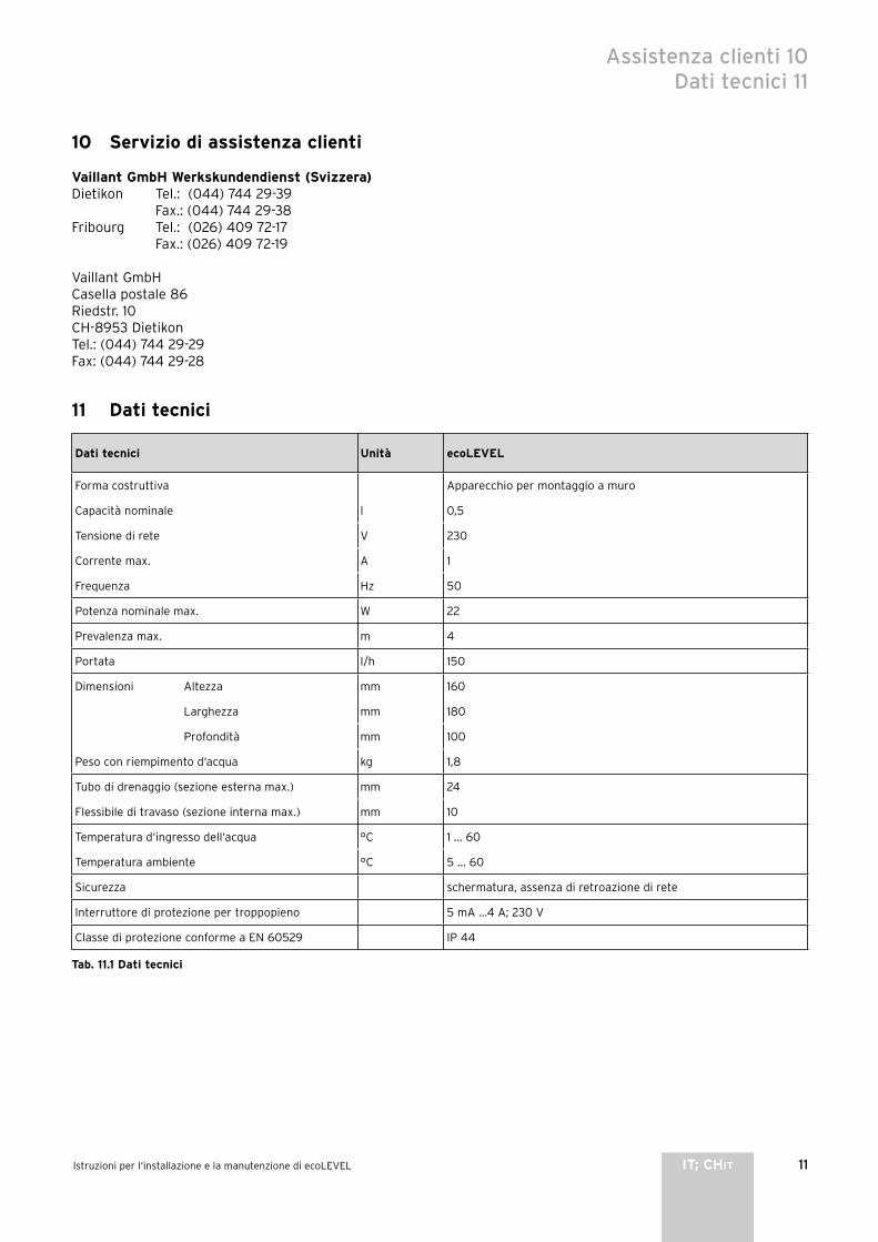
11Istruzioni per l‘installazione e la manutenzione di ecoLEVEL IT; CHIT
Assistenza clienti 10Dati tecnici 11
10 Servizio di assistenza clienti
Vaillant GmbH Werkskundendienst (Svizzera)Dietikon Tel.: (044) 744 29-39 Fax.: (044) 744 29-38Fribourg Tel.: (026) 409 72-17 Fax.: (026) 409 72-19
Vaillant GmbHCasella postale 86Riedstr. 10CH-8953 DietikonTel.: (044) 744 29-29Fax: (044) 744 29-28
11 Dati tecnici
Dati tecnici Unità ecoLEVEL
Forma costruttiva Apparecchio per montaggio a muro
Capacità nominale l 0,5
Tensione di rete V 230
Corrente max. A 1
Frequenza Hz 50
Potenza nominale max. W 22
Prevalenza max. m 4
Portata l/h 150
Dimensioni Altezza mm 160
Larghezza mm 180
Profondità mm 100
Peso con riempimento d‘acqua kg 1,8
Tubo di drenaggio (sezione esterna max.) mm 24
Flessibile di travaso (sezione interna max.) mm 10
Temperatura d‘ingresso dell‘acqua °C 1 ... 60
Temperatura ambiente °C 5 ... 60
Sicurezza schermatura, assenza di retroazione di rete
Interruttore di protezione per troppopieno 5 mA ...4 A; 230 V
Classe di protezione conforme a EN 60529 IP 44
Tab. 11.1 Dati tecnici


1Instrukcja obsługi ecoLEVEL PL
Spis treści
1 Informacje dotyczące instrukcji . . . . . . . . . . . . 21.1 Przechowywanie dokumentów . . . . . . . . . . . . . . . 21.2 Stosowane symbole . . . . . . . . . . . . . . . . . . . . . . . . . 2
2 Wskazówki i przepisy bezpieczeństwa . . . . . . . 2
3 Informacje dotyczące użytkowania . . . . . . . . . 33.1 Gwarancja fabryczna i odpowiedzialność . . . . . . 33.2 Przeznaczenie . . . . . . . . . . . . . . . . . . . . . . . . . . . . . . 33.3 Czyszczenie i konserwacja . . . . . . . . . . . . . . . . . . . 33.4 Recykling i usuwanie odpadów . . . . . . . . . . . . . . . 3
4 Obsługa i konserwacja . . . . . . . . . . . . . . . . . . . 34.1 Informacje ogólne . . . . . . . . . . . . . . . . . . . . . . . 34.2 Wskazania stanu pracy . . . . . . . . . . . . . . . . . . . . . . 34.3 Konserwacja . . . . . . . . . . . . . . . . . . . . . . . . . . . . . . . 4
Dla użytkownika
Instrukcja obsługi
ecoLEVEL
Pompa kondensatu
2 Instrukcja obsługi ecoLEVEL
1 Informacje dotyczące instrukcji
Przedstawione poniżej informacje stanowią pomoc w korzystaniu z instrukcji.Wraz z niniejszą instrukcją obsługi, instalacji i konserwacji obowiązują też pozostałe dokumenty.Za szkody spowodowane nieprzestrzeganiem tych instrukcji i dokumentów nie ponosimy odpowiedzialności.
Dokumenty dodatkowePodczas obsługi pompy kondensatu ecoLEVEL należy uwzględnić wszystkie instrukcje obsługi części i podzespołów instalacji. Instrukcje te dołączone są do poszczególnych części instalacji oraz podzespołów uzupełniających.
1.1 Przechowywanie dokumentówProsimy o staranne przechowywanie niniejszej instrukcji obsługi, instalacji i konserwacji oraz wszystkich innych obowiązujących dokumentów, aby w razie potrzeby można było w każdej chwili z nich skorzystać. W razie przeprowadzki lub sprzedaży pompy należy przekazać dokumentację nowemu użytkownikowi/ właścicielowi.
1.2 Stosowane symbolePodczas obsługi pompy należy przestrzegać wskazówek dotyczących bezpieczeństwa zawartych w niniejszej instrukcji obsługi!
Niebezpieczeństwo!Niebezpieczeństwo dla życia w wyniku porażenia prądem elektrycznym!
Niebezpieczeństwo!Bezpośrednie zagrożenie zdrowia i życia!
Uwaga!Możliwe zagrożenie dla urządzenia i środowiska naturalnego!
Wskazówka!Pożyteczne informacje i wskazówki.
• Symbol sygnalizujący konieczność działania
2 Wskazówki i przepisy bezpieczeństwa
Generalnie zabrania się dokonywania modyfikacji pompy kondensatu ecoLEVEL. Przeprowadzanie ewentualnych zmian lub modyfikacji w pompie lub w jej otoczeniu należy zawsze zlecać wykwalifikowanemu i autoryzowanemu instalatorowi.
Uwaga!Niebezpieczeństwo uszkodzenia w wyniku niewłaściwych modyfikacji!W żadnym wypadku nie wolno dokonywać zmian lub modyfikacji pompy lub innych części instalacji.
Instalowanie, uruchamianie i obsługa
Niebezpieczeństwo!Ostrzeżenie przed zagrażającym życiu napięciem elektrycznym!W pompie i na przewodach zasilających występują napięcia elektryczne zagrażające życiu. Dlatego instalacji lub otwarcia pompy może dokonać tylko wykwalifikowany i autoryzowany instalator.
Jest on odpowiedzialny za prawidłowy montaż i uruchomienie zgodnie z obowiązującymi przepisami. Odpowiada on również za przeprowadzanie przeglądu/ konserwacji pompy ecoLEVEL.- Pompy nie wolno używać do odpompowywania płynów
zapalnych i wybuchowych takich jak benzyna, olej opałowy itp.! Istnieje niebezpieczeństwo poparzenia lub wybuchu.
- Pompy nie należy używać w środowisku atmosfery wybuchowej, gdyż może to doprowadzić do wybuchu.
KondensatTłoczony przez pompę kondensat stanowi zagrożenie dla oczu w przypadku bezpośredniego kontaktu. Należy uważać, aby dzieci nie miały dostępu do pompy kondensatu ecoLEVEL.
1 Informacje dotyczące instrukcji2 Wskazówki i przepisy bezpieczeństwa

3Instrukcja obsługi ecoLEVEL PL
Informacje dotyczące użytkowania 3Obsługa i konserwacja 4
3 Informacje dotyczące użytkowania
3.1 Gwarancja fabryczna i odpowiedzialnośćGwarancji fabrycznej udzielamy tylko w przypadku instalacji wykonanej przez autoryzowany zakład serwisowy. Użytkownikowi pompy udzielamy dwuletniej gwarancji fabrycznej. Świadczenia gwarancyjne wykonywane są zasadniczo przez nasz personel serwisowy. Wszelkie koszty związane z przeprowadzeniem prac naprawczych w okresie obowiązywania gwarancji zostaną zwrócone tylko wtedy, gdy użytkownik otrzymał od nas odpowiednie zlecenie na przeprowadzenie tych prac i zaistniało roszczenie z tytułu gwarancji.
3.2 PrzeznaczeniePompę kondensatu ecoLEVEL należy używać tylko w połączeniu z elementami systemu firmy Vaillant, w których na skutek warunków eksploatacji jako produkt uboczny powstaje kondensat. Zalicza się do nich wszystkie kotły kondensacyjne marki Vaillant. Pompa we wszystkich jej komponentach przystosowana jest do tłoczenia kondensatu z instalacji grzewczych. Uwzględniono już przy tym wnikanie do systemu wody deszczowej przez układ spalinowy. Odnosi się to również do dozwolonej ilości, składu oraz zawartości ciał stałych w kondensacie.Pompa kondensatu nie jest przystosowana do tłoczenia innych płynnych lub stałych substancji. W szczególności wszelkiego rodzaju ścieki, chemikalia jak i emulsje zawierające oleje nie mogą być wprowadzane do pompy kondensatu. Inne stosowanie niż opisane wyżej, w szczególności tłoczenie niedozwolonych substancji, uważane jest za niezgodne z przeznaczeniem. Za wynikłe z tego powodu szkody producent lub dostawca nie ponoszą żadnej odpowiedzialności. Ryzyko takiego postępowania spoczywa wyłącznie na użytkowniku.Do użytkowania zgodnego z przeznaczeniem należy też przestrzeganie instrukcji obsługi i instalacji oraz warunków przeprowadzania konserwacji.
Uwaga!Zabrania się wszelkiego użytkowania niezgodnego z przeznaczeniem.
3.3 Czyszczenie i konserwacjaCzyścić powierzchnie zewnętrzne pompy nawilżoną ściereczką. Nie używać żadnych ostrych środków czyszczących!
3.4 Recykling i usuwanie odpadów Zarówno pompa, jak i opakowanie transportowe składają się w dużym stopniu z części wykonanych z materiałów nadających się do recyklingu.
PompaUszkodzonej pompy oraz innych części wyposażenia nie wolno wyrzucać do pojemników na odpady domowe. Zużytą pompę oraz części wyposażenia należy poddać recyklingowi zgodnie z obowiązującymi przepisami.
OpakowanieUsunięcie opakowania transportowego zlecić instalatorowi, który zainstalował pompę.
4 Obsługa i konserwacja
4.1 Informacje ogólnePompa kondensatu ecoLEVEL używana jest do odpompowywania skroplin powstających w kondensacyjnych instalacjach grzewczych. Powstające w kotłach kondensacyjnych skropliny dostają się przewodem wlotowym do pojemnika pompy.Dzięki stałemu pomiarowi poziomu wody, po osiągnięciu najwyższego poziomu napełnienia pompa włącza się samoczynnie i odpompowuje kondensat przewodem wylotowym.Pompa kondensatu ecoLEVEL wyposażona jest w przelewowy wyłącznik bezpieczeństwa. Przy odpowiednim podłączeniu wyłącza on kocioł, aby zapobiec przelewaniu się kondensatu w razie zakłócenia.
Wskazówka!Po zainstalowaniu i uruchomieniu pompy nie wymaga ona dodatkowej obsługi i pracuje automatycznie.
4.2 Wskazania stanu pracyW przedniej krawędzi obudowy pompy umieszczone są dwie diody, które sygnalizują stan pracy pompy kondensatu ecoLEVEL.Jeżeli pompa zasilana jest napięciem 230 V, świeci się zielona dioda LED. Oznacza to, że pompa jest gotowa do pracy.Czerwona dioda LED sygnalizuje, że woda przekroczyła najwyższy dopuszczalny poziom i włączył się przelewowy wyłącznik bezpieczeństwa.Jeżeli połączony jest on z kotłem, kocioł zostaje wyłączony, aby zapobiec powstawaniu dodatkowej ilości kondensatu.
Wskazówka!Jeżeli czerwona dioda LED pulsuje lub świeci się przez dłuższy okres, oznacza to, że nastąpiła awaria w instalacji lub uszkodzona jest pompa.Ustalenie przyczyny zakłócenia i naprawę pompy należy zlecić autoryzowanemu instalatorowi.

4 Instrukcja obsługi ecoLEVEL
4.3 KonserwacjaPompa kondensatu ecoLEVEL powinna być przynajmniej co 2 lata kontrolowana i czyszczona przez autoryzowanego instalatora.
4 Obsługa i konserwacja

1Instrukcja instalacji i konserwacji ecoLEVEL PL
Spis treści
1 Informacje dotyczące instrukcji . . . . . . . . . . . . 21.1 Przekazywanie i przechowywanie instrukcji . . . . 21.2 Stosowane symbole . . . . . . . . . . . . . . . . . . . . . . . . . 21.3 Oznaczenie CE . . . . . . . . . . . . . . . . . . . . . . . . . . . . . 21.4 Tabliczka znamionowa . . . . . . . . . . . . . . . . . . . . . . . 2
2 Wskazówki i przepisy bezpieczeństwa . . . . . . . 2
3 Informacje dotyczące instalowania i obsługi . 33.1 Gwarancja fabryczna i odpowiedzialność . . . . . . 33.2 Przeznaczenie . . . . . . . . . . . . . . . . . . . . . . . . . . . . . . 33.3 Recykling i usuwanie odpadów . . . . . . . . . . . . . . . 4
4 Montaż . . . . . . . . . . . . . . . . . . . . . . . . . . . . . . . . 44.1 Zakres dostawy . . . . . . . . . . . . . . . . . . . . . . . . . . . . 44.2 Wybór miejsca montażu . . . . . . . . . . . . . . . . . . . . . 44.3 Wymiary i wymagania przestrzenne . . . . . . . . . . . 44.4 Montaż uchwytu ściennego . . . . . . . . . . . . . . . . . . 4
5 Instalowanie . . . . . . . . . . . . . . . . . . . . . . . . . . . . 55.1 Podłączanie przewodu wlotowego . . . . . . . . . . . . 5
5.2 Podłączanie i poprowadzenie przewodu wylotowego . . . . . . . . . . . . . . . . . . . . . . . . . . . . . . . . 6
5.3 Podłączanie do kotła grzewczego . . . . . . . . . . . . . 6
6 Podłączanie do instalacji elektrycznej . . . . . . 76.1 Informacje ogólne . . . . . . . . . . . . . . . . . . . . . . . . . . 76.2 Podłączanie napięcia sieciowego 230 V . . . . . . . 76.3 Podłączanie przelewowego wyłącznika
bezpieczeństwa . . . . . . . . . . . . . . . . . . . . . . . . . . . . 7
7 Uruchamianie . . . . . . . . . . . . . . . . . . . . . . . . . . . 107.1 Wskazania stanu pracy . . . . . . . . . . . . . . . . . . . . . . 10
8 Konserwacja . . . . . . . . . . . . . . . . . . . . . . . . . . . . 10
9 Diagnoza i usuwanie zakłóceń . . . . . . . . . . . . . 109.1 Zakłócenia . . . . . . . . . . . . . . . . . . . . . . . . . . . . . . . . . 109.2 Diagnozowanie usterek . . . . . . . . . . . . . . . . . . . . . . 10
10 Serwis . . . . . . . . . . . . . . . . . . . . . . . . . . . . . . . . . 11
11 Dane techniczne . . . . . . . . . . . . . . . . . . . . . . . . 11
Dla instalatora
Instrukcja instalacji i konserwacji
ecoLEVEL
Pompa kondensatu

2 Instrukcja instalacji i konserwacji ecoLEVEL
1 Informacje dotyczące instrukcji
Przedstawione poniżej informacje stanowią pomoc w korzystaniu z instrukcji.Wraz z niniejszą instrukcją obsługi, instalacji i konserwacji obowiązują też pozostałe dokumenty.Za szkody spowodowane nieprzestrzeganiem tych instrukcji i dokumentów nie ponosimy odpowiedzialności.
Dokumenty dodatkowePodczas montażu i instalowania pompy kondensatu należy uwzględnić wszystkie instrukcje montażu i instalacji części i podzespołów instalacji. Instrukcje te dołączone są do poszczególnych części instalacji oraz podzespołów uzupełniających.
1.1 Przekazywanie i przechowywanie instrukcjiNiniejszą instrukcję obsługi, instalacji i konserwacji należy wręczyć użytkownikowi. Na nim spoczywa obowiązek starannego przechowywania instrukcji i udostępnienia jej w razie potrzeby.
1.2 Stosowane symbolePodczas instalacji i konserwacji pompy kondensatu należy przestrzegać wskazówek bezpieczeństwa zawartych w niniejszej instrukcji!
Niebezpieczeństwo!Niebezpieczeństwo dla życia w wyniku porażenia prądem elektrycznym!
Niebezpieczeństwo!Bezpośrednie zagrożenie zdrowia i życia!
Uwaga!Możliwe zagrożenie dla urządzenia i środowiska naturalnego!
Wskazówka!Pożyteczne informacje i wskazówki.
• Symbol sygnalizujący konieczność działania
1.3 Oznaczenie CEOznaczenie CE dokumentuje, iż zgodnie z tabliczką znamionową pompa kondensatu ecoLEVEL spełnia podstawowe wymagania następujących dyrektyw:- dopuszczalne napięcia elektryczne (dyrektywy EN 60
335-1 i EN 60 335-2-41),- kompatybilność elektromagnetyczna (dyrektywy EN
55 014-1 i EN 55 014-2).
1.4 Tabliczka znamionowaTabliczka znamionowa z numerem seryjnym klasą ochrony, napięciem zasilania, częstotliwością i oznakowaniem CE znajduje się pod spodem pompy ecoLEVEL.
2 Wskazówki i przepisy bezpieczeństwa
Niebezpieczeństwo!Ostrzeżenie przed zagrażającym życiu napięciem elektrycznym!W pompie i na przewodach zasilających występują napięcia elektryczne zagrażające życiu. Dlatego instalacji lub otwarcia pompy może dokonać tylko wykwalifikowany i autoryzowany instalator.
Normy i przepisyIEC 60364-7-712 Instalacje elektryczne w budynkach - część 7-712Procedura kontrolna EMC zgodnie z EN50081-1:1992,EN50082-1:1997 Emisja zakłóceń: EN 55014-1: 1993 Odporność na zakłócenia: EN 55014-2: 1997
Przepisy techniczneMontaż musi odpowiadać miejscowym uwarunkowaniom, przepisom i obowiązującym zasadom techniki.
Przepisy bhpPompę kondensatu może zainstalować tylko autoryzowany instalator. Odpowiada on za przestrzeganie obowiązujących norm i przepisów.Prawidłowa i bezpieczna praca pompy uzależniona jest od prawidłowego transportu, prawidłowego przechowywania, ustawienia i montażu oraz starannej obsługi i konserwacji.
Tylko instalatorzy, którzy zapoznali się ze wszystkimi wskazówkami bezpieczeństwa oraz zaleceniami dotyczącymi montażu, obsługi i konserwacji zawartymi w instrukcji obsługi i instalacji, mogą wykonywać prace przy pompie kondensatu.Podczas pracy pompy niektóre elementy pompy znajdują się pod niebezpiecznym napięciem elektrycznym, które może doprowadzić do obrażeń ciała lub śmierci.Celem zmniejszenia niebezpieczeństwa dla zdrowia i życia należy przestrzegać następujących środków bezpieczeństwa:1. Montaż pompy musi być wykonany zgodnie z zasadami
bezpieczeństwa oraz innymi obowiązującymi przepisami krajowymi lub lokalnymi. Należy zatroszczyć się o prawidłowe wykonanie uziemienia, prawidłowe obliczenie długości i przekrojów przewodów oraz wykonanie właściwego zabezpieczenia przeciwzwarciowego, tak aby zapewnić bezpieczne działanie pompy.
2. Otwarcia dolnej pokrywy dokonać może tylko autoryzowany instalator. Pokrywę dolną można otworzyć tylko wtedy, gdy wszystkie połączenia elektryczne zostaną odłączone.
3. Przed przeprowadzeniem kontroli wzrokowej i prac konserwacyjnych należy upewnić się, czy zasilanie elektryczne jest wyłączone i zabezpieczone przed
1 Informacje dotyczące instrukcji2 Wskazówki i przepisy bezpieczeństwa

3Instrukcja instalacji i konserwacji ecoLEVEL PL
ponownym włączeniem. Jeżeli konieczne jest wykonanie pomiarów przy włączonym zasilaniu elektrycznym, w żadnym wypadku nie wolno dotykać przyłączy. Należy przy tym zdjąć wszelkie ozdoby z rąk i palców. Należy sprawdzić stan przyrządów kontrolnych.
4. Podczas prac przy włączonej pompie należy stanąć na izolowanym podłożu, a więc zapewnić, aby nie było ono uziemione.
5. Należy przestrzegać poleceń zawartych w tej instrukcji obsługi, instalacji i konserwacji i stosować się do wszystkich wskazówek bezpieczeństwa i ostrzeżeń.
6. Lista ta nie zawiera pełnego zestawienia koniecznych środków bezpieczeństwa zapewniających bezpieczną pracę pompy. Jeżeli wystąpią specjalne problemy, które dla ułatwienia nie są wystarczająco szczegółowo opisane, należy zwrócić się do autoryzowanego sprzedawcy.
Wskazówki dotyczące bezpieczeństwa- Pompy nie wolno używać do odpompowywania płynów
zapalnych i wybuchowych takich jak benzyna, olej opałowy itp.! Istnieje niebezpieczeństwo poparzenia lub wybuchu.
- Pompy nie należy używać w środowisku atmosfery wybuchowej, gdyż może to doprowadzić do wybuchu.
- Przyłącze pompy wyposażone jest w przewód ochronny uziemiający.Należy upewnić się, czy zasilanie elektryczne zostało uziemione zgodnie z ustawowymi przepisami.
- Do wyłącznika bezpieczeństwa należy podłączyć urządzenie przerywające dopływ prądu lub alarmowe, aby w przypadku uszkodzenia pompy uniknąć szkód z powodu wypływu kondensatu lub uszkodzenia kotła.
- Upewnić się, czy pompa w czasie pracy stoi na stabilnym podłożu lub przymocowana jest do ściany, gdyż w przeciwnym razie może dojść do zakłóceń w działaniu pompy. Może to doprowadzić do uszkodzenia pompy lub kotła.
- Przewód odpływowy kondensatu nie może być połączony szczelnie z przewodem kanalizacyjnym.Niebezpieczeństwo zatrucia spalinami! Zawartość wewnętrznego syfonu kotła może zostać całkowicie wyssana.
- Jeśli podczas instalowania kotła okaże się, że przewód odpływowy kondensatu musi zostać przedłużony, to należy stosować wyłącznie rury odpływowe dopuszczone przez normę DIN 1986-4. Używanie niewłaściwych rur odpływowych może doprowadzić do nieszczelności i powstania szkód spowodowanych wypływającym kondensatem.
Zmiany i modyfikacjeGeneralnie zabrania się dokonywania modyfikacji pompy. Dokonywanie zmian w otoczeniu pompy jest dozwolone tylko wtedy, gdy odpowiadają one normom krajowym.
Uwaga!Niebezpieczeństwo uszkodzenia w wyniku niewłaściwych modyfikacji!W żadnym wypadku nie wolno dokonywać zmian lub modyfikacji pompy lub innych części instalacji.
3 Informacje dotyczące instalowania i obsługi
3.1 Gwarancja fabryczna i odpowiedzialnośćGwarancji fabrycznej udzielamy tylko w przypadku instalacji wykonanej przez autoryzowany zakład serwisowy. Użytkownikowi pompy udzielamy dwuletniej gwarancji fabrycznej. Świadczenia gwarancyjne wykonywane są zasadniczo przez nasz personel serwisowy. Wszelkie koszty związane z przeprowadzeniem prac naprawczych w okresie obowiązywania gwarancji zostaną zwrócone tylko wtedy, gdy użytkownik otrzymał od nas odpowiednie zlecenie na przeprowadzenie tych prac i zaistniało roszczenie z tytułu gwarancji.
3.2 PrzeznaczeniePompę kondensatu należy używać tylko w połączeniu z elementami systemu firmy Vaillant, w których na skutek warunków eksploatacji jako produkt uboczny powstaje kondensat. Zalicza się do nich wszystkie kotły kondensacyjne marki Vaillant. Pompa we wszystkich jej komponentach przystosowana jest do tłoczenia kondensatu z instalacji grzewczych. Uwzględniono już przy tym wnikanie do systemu wody deszczowej przez układ spalinowy. Odnosi się to również do dozwolonej ilości, składu oraz zawartości ciał stałych w kondensacie.Pompa kondensatu nie jest przystosowana do tłoczenia innych płynnych lub stałych substancji. W szczególności wszelkiego rodzaju ścieki, chemikalia jak i emulsje zawierające oleje nie mogą być wprowadzane do pompy kondensatu. Inne stosowanie niż opisane wyżej, w szczególności tłoczenie niedozwolonych substancji, uważane jest za niezgodne z przeznaczeniem. Za wynikłe z tego powodu szkody producent lub dostawca nie ponoszą żadnej odpowiedzialności. Ryzyko takiego postępowania spoczywa wyłącznie na użytkowniku.Do użytkowania zgodnego z przeznaczeniem należy też przestrzeganie instrukcji obsługi i instalacji oraz warunków przeprowadzania konserwacji.
Uwaga!Zabrania się wszelkiego użytkowania niezgodnego z przeznaczeniem.
Wskazówki i przepisy bezpieczeństwa 2Informacje dotyczące instalowania i obsługi 3
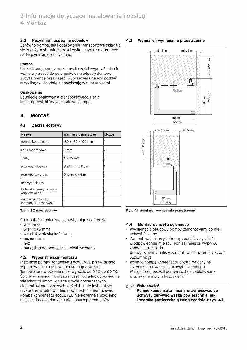
4 Instrukcja instalacji i konserwacji ecoLEVEL
3.3 Recykling i usuwanie odpadów Zarówno pompa, jak i opakowanie transportowe składają się w dużym stopniu z części wykonanych z materiałów nadających się do recyklingu.
PompaUszkodzonej pompy oraz innych części wyposażenia nie wolno wyrzucać do pojemników na odpady domowe. Zużytą pompę oraz części wyposażenia należy poddać recyklingowi zgodnie z obowiązującymi przepisami.
OpakowanieUsunięcie opakowania transportowego zlecić instalatorowi, który zainstalował pompę.
4 Montaż
4.1 Zakres dostawy
Nazwa Wymiary gabarytowe Liczba
pompa kondensatu 180 x 160 x 100 mm 1
kołki montażowe 5 mm 2
śruby 4 x 35 mm 2
przewód wlotowy Ø 24 mm x 1,15 m 1
przewód wylotowy Ø 10 mm x 6 m 1
uchwyt ścienny - 1
Uchwyt ścienny do węża odpływowego
- 6
instrukcja obsługi, instalacji i konserwacji
- 1
Tab. 4.1 Zakres dostawy
Do montażu konieczne są następujące narzędzia:- wiertarka- wiertło (5 mm)- wkrętak z płaską końcówką- poziomnica- nóż- narzędzia do podłączania elektrycznego
4.2 Wybór miejsca montażuInstalację pompy kondensatu ecoLEVEL przewidziano w pomieszczeniu ustawienia kotła grzewczego. Temperatura otoczenia musi wynosić od 5 °C do 60 °C.Ściany w miejscu montażu muszą posiadać odpowiednie właściwości umożliwiające użycie dostarczanych elementów montażowych. Jeżeli tak nie jest, należy przygotować odpowiednie powierzchnie montażowe. Pompa kondensatu ecoLEVEL nie powinna służyć jako miejsce do odkładania na niej innych przedmiotów.
4.3 Wymiary i wymagania przestrzenne
100 mm
90 mm
165 mm
115
mm
150
mm
175 mm
min
. 20
0 m
m
min. 5 mm min. 5 mm
min
. 20
0 m
m
min. 5 mm min. 5 mm
Rys. 4.1 Wymiary i wymagania przestrzenne
4.4 Montaż uchwytu ściennego• Wyciągnąć z obudowy pompy zamontowany do niej
uchwyt ścienny.• Zamontować uchwyt ścienny zgodnie z rys. 4.2
w odpowiednim miejscu, poniżej miejsca wypływu kondensatu z kotła.Uchwyt ścienny należy zamontować poziomo! Używać poziomnicy!
• Wsunąć pompę kondensatu prosto od góry na krawędzie prowadzące uchwytu ściennego.W najniższej pozycji pompa zostaje zablokowana w uchwycie małym haczykiem.
Wskazówka!Pompę kondensatu można przymocować do uchwytu zarówno wąską powierzchnią, jak i szeroką powierzchnią tylną zgodnie z rys. 4.1.
3 Informacje dotyczące instalowania i obsługi4 Montaż

5Instrukcja instalacji i konserwacji ecoLEVEL PL
A
B
Rys. 4.2 Montaż uchwytu ściennego
5 Instalowanie
Uwaga!Przewody podłączyć dopiero wtedy, gdy zawór zwrotny (1) i pokrywa (2) są zdemontowane.Wywieranie nadmiernej siły w czasie montażu można uszkodzić pompę i uchwyt ścienny.
5.1 Podłączanie przewodu wlotowego
Uwaga!Przewód wlotowy należy poprowadzić od kotła do pompy kondensatu ecoLEVEL ze stałym spadkiem i bez pętli, gdyż w przeciwnym razie skropliny nie będą mogły bez przeszkód spływać do pompy.
• Określić odpowiednią długość przewodu.• Przewód skracać tak, aby zostało co najmniej 10 mm
na końcu przewodu do wprowadzenia w pokrywę pompy.
• Przekręcić zawór zwrotny (1) o jedną czwartą obrotu w lewo, aby otworzyć pokrywę (2) pompy.Powoduje to odblokowanie pokrywy i zaworu zwrotnego.
• Wyciągnąć pokrywę i zawór zwrotny do góry.
1
3
4 2
Rys. 5.1 Demontaż zaworu zwrotnego i pokrywy
• Włożyć do oporu przewód wlotowy do otworu wlotowego (3) zdjętej pokrywy.
Wskazówka!Jeżeli ma być podłączony drugi przewód, należy usunąć zatyczkę z drugiego otworu wlotowego (4) i podłączyć przewód zgodnie z opisem wyżej.
• Nałożyć ponownie pokrywę pompy kondensatu ecoLEVEL.
Montaż 4Instalowanie 5

6 Instrukcja instalacji i konserwacji ecoLEVEL
5.2 Podłączanie i poprowadzenie przewodu wylotowego
• Nałożyć przewód wylotowy do oporu na zdemontowany zawór zwrotny.
• Włożyć zawór zwrotny w pokrywę i zablokować poprzez obrót o jedną czwartą w prawo.
Poprowadzenie przewodu wylotowego:Koniec przewodu wylotowego pompy powinien być włożony do kanalizacji budynku.• Przewód wylotowy pompy poprowadzić bezpośrednio
z pompy do góry na dostateczną wysokość, aby zniwelować różnicę wysokości pomiędzy wyjściem pompy a odpływem i po zawróceniu go poprowadzić spadkiem do odpływu.
Uwaga!Przestrzegać maksymalnej wysokości tłoczenia pompy 4 m!
• Poprowadzić przewód odpływowy ze stałym spadkiem do odpowiedniego odpływu.
• Poprowadzić przewód odpływowy w najwyższym miejscu w kształcie litery U do zabezpieczenia przed strumieniem powrotnym.
m
ax. 4
,0 m
ca 3˚
Rys. 5.2 Poprowadzenie przewodu wylotowego
5.3 Podłączanie do kotła grzewczegoZa pomocą dostarczanego przewodu wlotowego można podłączyć pompę kondensatu ecoLEVEL do syfonu wszystkich kotłów kondensacyjnych firmy Vaillant.• Jeżeli przewód wylotowy kondensatu kotła jest
wystarczająco długi, można go podłączyć bezpośrednio do pompy (patrz rozdział 5.1).
Jeżeli przewód kotła jest za krótki, należy go zastąpić dostarczonym przewodem wlotowym.• Przewód ten należy podłączyć do wylotu kondensatu
kotła.• Przewód wlotowy należy podłączyć do pompy
kondensatu ecoLEVEL zgodnie z rozdziałem 5.1.
5 Instalowanie

7Instrukcja instalacji i konserwacji ecoLEVEL PL
6 Podłączanie do instalacji elektrycznej
6.1 Informacje ogólnePo zamontowaniu pompy kondensatu ecoLEVEL można przystąpić do podłączenia zasilania elektrycznego.Zasilanie elektryczne pompy doprowadzane jest przewodem (1) z wolną końcówką.Przelewowy wyłącznik bezpieczeństwa podłączany jest do kotła kablem (2).Podłączenie instalacji elektrycznej może wykonać tylko wykwalifikowany elektryk.
Niebezpieczeństwo!Niebezpieczeństwo dla życia w wyniku porażenia prądem elektrycznym! W przypadku niewłaściwej instalacji istnieje niebezpieczeństwo porażenia prądem elektrycznym i uszkodzenia urządzenia.
Podczas wykonywania podłączenia zasilania elektrycznego należy odłączyć pompę i kocioł od napięcia elektrycznego i zabezpieczyć przed ponownym włączeniem.
Wskazówka!Wszystkie połączenia elektryczne i przewodzące kondensat do pompy muszą być wolne od napięcia elektrycznego.
1
2
Rys. 6.1 Przegląd przyłączy elektrycznych
Legenda1 przewód zasilający 230 V (w razie potrzeby: możliwość
podłączenia wtyczki)2 przewód przyłączeniowy przelewowego wyłącznika
bezpieczeństwa
6.2 Podłączanie napięcia sieciowego 230 VPodłączenie napięcia sieciowego 230 V można wykonać na dwa sposoby:• podłączyć przewód (1) do sieci 230 V poprzez wyjście
zasilania sieciowego kotłalub• zamontować wtyczkę sieciową do przewodu (1)
i podłączyć pompę poprzez gniazdo wtykowe (wtyczka nie należy do zakresu dostawy).
6.3 Podłączanie przelewowego wyłącznika bezpieczeństwa
Sposób podłączenia na płytce elektronicznej zależy od typu kotła.Sposób podłączenia w zależności od typu kotła można odczytać z poniższej tabeli:
Kraj Kocioł grzewczyPodłączanie przelewowego wyłącznika bezpieczeństwa
PL ecoTEC sposób podłączenia A
PL ecoTEC plus sposób podłączenia B
PL ecoTEC pro sposób podłączenia B
PL ecoVIT sposób podłączenia A
PL ecoCOMPACT sposób podłączenia A
Tab. 6.1 Sposoby podłączania dla różnych typów kotła
Opis odpowiednich sposobów podłączania podany jest w kolejnych rozdziałach.
Podłączanie do instalacji elektrycznej 6

8 Instrukcja instalacji i konserwacji ecoLEVEL
Sposób podłączenia A:Podłączyć przelewowy wyłącznik bezpieczeństwa do obwodu niskonapięciowego kotła w następujący sposób:• Otworzyć skrzynkę rozdzielczą kotła.• Usunąć z płytki elektronicznej kotła mostek kablowy na
niebieskim gnieździe wtykowym „termostatu przylgowego“.
• Do gniazda tego podłączyć przewód pompy kondensatu ecoLEVEL z niebieskim wtykiem Pro E.
98
75
43
NL
NL
Pu
mp
e 2
. Pu
mp
eA
nl -
Th
erm
L N
24
V I
23
0V
RT
24
V2
30
VR
T 2
30
V
X 10
X 7
X 8
X 2
13
11
1
1
Co
die
rwid
erstan
d
1
2
Rys. 6.2 Podłączanie przelewowego wyłącznika bezpieczeństwa,
sposób podłączenia A
6 Podłączanie do instalacji elektrycznej

9Instrukcja instalacji i konserwacji ecoLEVEL PL
Podłączanie do instalacji elektrycznej 6
Sposób podłączenia B:Podłączyć przelewowy wyłącznik bezpieczeństwa do obwodu niskonapięciowego kotła w następujący sposób:• Otworzyć skrzynkę rozdzielczą kotła.• Podłączyć pasującą wtyczkę do krawędziowego
gniazda wtykowego X40.
1
Rys. 6.3 Podłączanie przelewowego wyłącznika bezpieczeństwa,
sposób podłączenia B
Wskazówka!Jeżeli w kotle grzewczym wbudowany jest moduł wielo funkcyjny 2 z 7 (nr wyrobu 00 2001 7744), gniaz do wtykowe X40 jest już zajęte. W takim wypadku wtyk podłącza się do gniazda X40B modułu wielo funkcyjnego 2 z 7.Patrz instrukcja modułu wielofunkcyjnego.

10 Instrukcja instalacji i konserwacji ecoLEVEL
7 Uruchamianie
Po mechanicznym i elektrycznym zainstalowaniu pompy kondensatu ecoLEVEL jest ona gotowa do pracy. Świeci się zielona dioda LED.
Wskazówka!Po zainstalowaniu i uruchomieniu pompy nie wymaga ona dodatkowej obsługi i pracuje automatycznie.
7.1 Wskazania stanu pracyW przedniej krawędzi obudowy pompy umieszczone są dwie diody, które sygnalizują stan pracy pompy kondensatu.Następujące stany pracy sygnalizowane są przez zieloną diodę LED:
Zielona dioda LED
Czerwona dioda LED
Znaczenie
świeci się wył.pompa jest zasilana napięciem sieciowym 230 V
pulsuje wył.pompa pracuje i odpompowuje kondensat
Jeżeli czerwona dioda LED pulsuje lub świeci się, ozna cza to, że nastąpiło zakłócenie. Patrz rozdział 9.
8 Konserwacja
Uwaga!Niebezpieczeństwo dla życia w wyniku porażenia prądem elektrycznym na przyłączach pod napięciem. Przed pracami zawsze odłączyć najpierw dopływ prądu do pompy i do kotła. Dopiero potem można przystąpić do konserwacji.
• Upewnić się, czy dopływy i odpływy nie są zatkane.• Usunąć pokrywę pompy i skontrolować pojemnik
kondensatu, czy nie jest zanieczyszczony. W razie potrzeby wyczyścić pojemnik kondensatu ciepłą wodą i łagodnym środkiem czyszczącym.
• Wymontować zawór zwrotny i oczyścić go, przepłukując strumieniem wody.
• Sprawdzić przewody dopływu i odpływu i ewentualnie wyczyścić.
• Upewnić się, czy przewody nie są zgięte, aby zapewnić swobodny przepływ kondensatu.
Wskazówka!Konserwacja pompy może być połączona z częstością przeprowadzania prac konserwacyjnych kotła. Pompę należy czyścić przynajmniej raz w roku.
9 Diagnoza i usuwanie zakłóceń
9.1 ZakłóceniaPompa kondensatu ecoLEVEL usuwa samoczynnie krótkotrwałe zakłócenia funkcji. Następujące stany pracy sygnalizowane są przez czerwoną diodę LED:
Zielona dioda LED
Czerwona dioda LED
Znaczenie
pulsuje świeci sięNajwyższy dozwolony poziom wody w pompie jest przekroczony.Zbiornik jest odpompowywany.
pulsuje pulsuje
Pompa znajduje się przez zaprogramowany okres w pozycji spoczynku i ponownie uruchamia się samoczynnie.
Jeżeli czerwona dioda LED świeci się lub pulsuje, oznacza to, że woda przekroczyła najwyższy dopuszczalny poziom i włączył się przelewowy wyłącznik bezpieczeństwa. Otwiera się zestyk bezpotencjałowy, wzgl. przerywany jest obwód prądu, aby wyłączyć kocioł.Jeżeli połączony jest on z kotłem, kocioł zostaje wyłączony, aby zapobiec powstawaniu dodatkowej ilości kondensatu.
9.2 Diagnozowanie usterekJeżeli czerwona dioda LED pulsuje lub świeci się przez dłuższy okres, oznacza to, że nastąpiła awaria w instalacji lub uszkodzona jest pompa.Celem usunięcia zakłócenia należy sprawdzić następujące punkty:
Przyczyna Usuwanie zakłóceń
pompa nie tłoczy:zgięty przewód wylotowy pompy
usunąć zagięcie
silnik zablokowanykontrola wzrokowa wlotu silnika: skontrolować obecność ciał obcych i ewent. usunąć
uszkodzony silnik wymienić pompę
pompa nie napełnia się
skontrolować przewody wlotowe pod kątem sposobu poprowadzenia, zatkania i stabilnego zamocowania w pompie, ewent. usunąć zakłócenie
pływak pomocniczy zablokowany
odblokować pływak pomocniczy
7 Uruchamianie8 Konserwacja9 Diagnoza i usuwanie zakłóceń

11Instrukcja instalacji i konserwacji ecoLEVEL PL
Serwis 11Dane techniczne 10
10 SerwisW przypadku pytań dotyczących instalacji urządzenia lub spraw serwisowych, prosimy o kontakt z Infolinią Vaillant : 0 801 804 444
11 Dane techniczne
Dane techniczneJednostki miary
ecoLEVEL
Typ konstrukcyjny pompa do montażu na ścianie
Pojemność znamionowa l 0,5
Napięcie sieciowe V 230
Maks. prąd A 1
Częstotliwość Hz 50
Maks. moc znamionowa W 22
Maks. wysokość tłoczenia m 4
Wydajność tłoczenia l/h 150
Wymiary gabarytowe Wysokość
mm 160
Szerokość mm 180
Głębokość mm 100
Ciężar pompy napełnionej wodą kg 1,8
Przewód wlotowy (maks. średnica zewnętrzna) mm 24
Przewód wylotowy (min. średnica wewnętrzna) mm 10
Temperatura wody na zasilaniu °C 1 ... 60
Temperatura otoczenia °C 5 ... 60
Bezpieczeństwowyeliminowane zakłócenia radiowe, brak wstecznego oddziaływania na sieć elektryczną
Przelewowy wyłącznik bezpieczeństwa 5 mA ...4 A; 230 V
Stopień ochrony według EN 60529 IP 44
Tab. 11.1 Dane techniczne


00
20
017
50
7_0
0 G
B; D
E; A
T; C
H; B
E; N
L; I
T; P
L
12
20
05