0 r spartan-3e fpga family: complete data...
TRANSCRIPT

DS312 March 21, 2005 www.xilinx.com 1
© 2005 Xilinx, Inc. All rights reserved. XILINX, the Xilinx logo, and other designated brands included herein are trademarks of Xilinx, Inc. All other trademarks are the property of their respective owners.
Module 1: Introduction and Ordering InformationDS312-1 (v1.1) March 21, 20056 pages
• Introduction • Features • Architectural Overview • Package Marking• Ordering Information
Module 2: Functional DescriptionDS312-2 (v1.1) March 21, 200596 pages
• Input/Output Blocks (IOBs)- Overview - SelectIO™ Signal Standards
• Configurable Logic Block (CLB)• Block RAM • Dedicated Multipliers • Digital Clock Manager (DCM) • Clock Network • Configuration • Powering Spartan-3E FPGAs
Module 3: DC and Switching CharacteristicsDS312-3 (v1.0) March 1, 200518 pages
• DC Electrical Characteristics - Absolute Maximum Ratings - Supply Voltage Specifications- Recommended Operating Conditions - DC Characteristics
• Switching Characteristics - DCM Timing- Configuration and JTAG Timing
Module 4: Pinout DescriptionsDS312-4 (v1.1) March 21, 200572 pages
• Pin Descriptions • Package Overview • Pinout Tables • Footprint Diagrams
IMPORTANT NOTE: The Spartan™-3E FPGA data sheet is created and published in separate modules. This completeversion is provided for easy downloading and searching of the complete document. Page, figure, and table numbers beginat 1 for each module, and each module has its own Revision History at the end. Use the PDF "Bookmarks" for easynavigation in this volume.
0
Spartan-3E FPGA Family: Complete Data Sheet
DS312 March 21, 2005 0 0
R

IntroductionThe Spartan™-3E family of Field-Programmable GateArrays (FPGAs) is specifically designed to meet the needsof high volume, cost-sensitive consumer electronic applica-tions. The five-member family offers densities ranging from100,000 to 1.6 million system gates, as shown in Table 1.
The Spartan-3E family builds on the success of the earlierSpartan-3 family by increasing the amount of logic per I/O,significantly reducing the cost per logic cell. New featuresimprove system performance and reduce the cost of config-uration. These Spartan-3E enhancements, combined withadvanced 90 nm process technology, deliver more function-ality and bandwidth per dollar than was previously possible,setting new standards in the programmable logic industry.
Because of their exceptionally low cost, Spartan-3E FPGAsare ideally suited to a wide range of consumer electronicsapplications, including broadband access, home network-ing, display/projection, and digital television equipment.
The Spartan-3E family is a superior alternative to mask pro-grammed ASICs. FPGAs avoid the high initial cost, thelengthy development cycles, and the inherent inflexibility ofconventional ASICs. Also, FPGA programmability permitsdesign upgrades in the field with no hardware replacementnecessary, an impossibility with ASICs.
Features• Very low cost, high-performance logic solution for
high-volume, consumer-oriented applications• Proven advanced 90-nanometer process technology• Multi-voltage, multi-standard SelectIO™ interface pins
- Up to 376 I/O pins or 156 differential signal pairs- LVCMOS, LVTTL, HSTL, and SSTL single-ended
signal standards
- True LVDS, RSDS, mini-LVDS differential I/O- 3.3V, 2.5V, 1.8V, 1.5V, and 1.2V signaling- Enhanced Double Data Rate (DDR) support
• Abundant, flexible logic resources- Densities up to 33,192 logic cells, including
optional shift register or distributed RAM support- Efficient wide multiplexers, wide logic- Fast look-ahead carry logic- Enhanced 18 x 18 multipliers with optional pipeline- IEEE 1149.1/1532 JTAG programming/debug port
• Hierarchical SelectRAM™ memory architecture- Up to 648 Kbits of fast block RAM - Up to 231 Kbits of efficient distributed RAM
• Up to eight Digital Clock Managers (DCMs)- Clock skew elimination (delay locked loop)- Frequency synthesis, multiplication, division- High-resolution phase shifting- Wide frequency range (5 MHz to over 300 MHz)
• Eight global clocks and eight clocks for each half of device, plus abundant low-skew routing
• Configuration interface to industry-standard PROMs- Low-cost, space-saving SPI serial Flash PROM- x8 or x8/x16 parallel NOR Flash PROM- Low-cost Xilinx Platform Flash with JTAG
• Complete Xilinx ISE™, WebPACK™ development system support
• MicroBlaze™, PicoBlaze™ embedded processor cores• Fully compliant 32-/64-bit 33/66 MHz PCI support • Low-cost QFP and BGA packaging options
- Common footprints support easy density migration- Pb-free packaging options
06
Spartan-3E FPGA Family: Introduction and Ordering Information
DS312-1 (v1.1) March 21, 2005 0 0 Advance Product Specification
R
Table 1: Summary of Spartan-3E FPGA Attributes
DeviceSystem Gates
Equivalent Logic Cells
CLB Array (One CLB = Four Slices)
Distributed RAM bits(1)
Block RAM bits(1)
Dedicated Multipliers DCMs
Maximum User I/O
Maximum Differential
I/O PairsRows ColumnsTotalCLBs
TotalSlices
XC3S100E 100K 2,160 22 16 240 960 15K 72K 4 2 108 40
XC3S250E 250K 5,508 34 26 612 2,448 38K 216K 12 4 172 68
XC3S500E 500K 10,476 46 34 1,164 4,656 73K 360K 20 4 232 92
XC3S1200E 1200K 19,512 60 46 2,168 8,672 136K 504K 28 8 304 124
XC3S1600E 1600K 33,192 76 58 3,688 14,752 231K 648K 36 8 376 156
Notes: 1. By convention, one Kb is equivalent to 1,024 bits.
DS312-1 (v1.1) March 21, 2005 www.xilinx.com 1Advance Product Specification
© 2005 Xilinx, Inc. All rights reserved. XILINX, the Xilinx logo, and other designated brands included herein are trademarks of Xilinx, Inc. All other trademarks are the property of their respective owners.

Introduction and Ordering InformationR
Architectural OverviewThe Spartan-3E family architecture consists of five funda-mental programmable functional elements:
• Configurable Logic Blocks (CLBs) contain flexible Look-Up Tables (LUTs) that implement logic plus storage elements used as flip-flops or latches. CLBs perform a wide variety of logical functions as well as store data.
• Input/Output Blocks (IOBs) control the flow of data between the I/O pins and the internal logic of the device. Each IOB supports bidirectional data flow plus 3-state operation. Supports a variety of signal standards, including four high-performance differential standards. Double Data-Rate (DDR) registers are included.
• Block RAM provides data storage in the form of 18-Kbit dual-port blocks.
• Multiplier Blocks accept two 18-bit binary numbers as inputs and calculate the product.
• Digital Clock Manager (DCM) Blocks provide self-calibrating, fully digital solutions for distributing, delaying, multiplying, dividing, and phase-shifting clock signals.
These elements are organized as shown in Figure 1. A ringof IOBs surrounds a regular array of CLBs. Each device hastwo columns of block RAM except for the XC3S100E, whichhas one column. Each RAM column consists of several18-Kbit RAM blocks. Each block RAM is associated with adedicated multiplier. The DCMs are positioned in the centerwith two at the top and two at the bottom of the device. TheXC3S100E has only one DCM at the top and bottom, whilethe XC3S1200E and XC3S1600E add two DCMs in themiddle of the left and right sides.
The Spartan-3E family features a rich network of traces thatinterconnect all five functional elements, transmitting sig-nals among them. Each functional element has an associ-ated switch matrix that permits multiple connections to therouting.
Figure 1: Spartan-3E Family Architecture
Notes: 1. The XC3S1200E and XC3S1600E have two additional DCMs on both the left and right sides as
indicated by the dashed lines. The XC3S100E has only one DCM at the top and one at the bottom.
2 www.xilinx.com DS312-1 (v1.1) March 21, 2005Advance Product Specification

Introduction and Ordering InformationR
ConfigurationSpartan-3E FPGAs are programmed by loading configura-tion data into robust, reprogrammable, static CMOS config-uration latches (CCLs) that collectively control all functionalelements and routing resources. The FPGA’s configurationdata is stored externally in a PROM or some other non-vol-atile medium, either on or off the board. After applyingpower, the configuration data is written to the FPGA usingany of seven different modes:
• Master Serial from a Xilinx Platform Flash PROM• Serial Peripheral Interface (SPI) from an
industry-standard SPI serial Flash• Byte Peripheral Interface (BPI) Up or Down from an
industry-standard x8 or x8/x16 parallel NOR Flash• Slave Serial, typically downloaded from a processor• Slave Parallel, typically downloaded from a processor• Boundary Scan (JTAG), typically downloaded from a
processor or system tester.
I/O CapabilitiesThe Spartan-3E FPGA SelectIO interface supports manypopular single-ended and differential standards. Table 2shows the number of user I/Os as well as the number of dif-ferential I/O pairs available for each device/package combi-nation.
Spartan-3E FPGAs support the following single-endedstandards:
• 3.3V, low-voltage TTL, LVTTL• Low-voltage CMOS (LVCMOS) at 3.3V, 2.5V, 1.8V,
1.5V, or 1.2V• 3.3V PCI at 33 MHz and 66 MHz• HSTL I and III at 1.8V, typically for memory applications• SSTL I at 1.8V and 2.5V, typically for memory
applications
Spartan-3E FPGAs support the following differential stan-dards:
• LVDS• Bus LVDS• mini-LVDS• RSDS
Table 2: Available User I/Os and Differential (Diff) I/O Pairs
Device
VQ100VQG100
CP132CPG132
TQ144TQG144
PQ208PQG208
FT256FTG256
FG320FGG320
FG400FGG400
FG484FGG484
User Diff User Diff User Diff User Diff User Diff User Diff User Diff User Diff
XC3S100E 66 30 - - 108 40 - - - - - - - - - -
XC3S250E 66 30 92 41 108 40 158 65 172 68 - - - - - -
XC3S500E - - 92 41 - - 158 65 190 77 232 92 - - - -
XC3S1200E - - - - - - - - 190 77 250 99 304 124 - -
XC3S1600E - - - - - - - - - - 250 99 304 124 376 156
Notes: 1. All Spartan-3E devices in the same package are pin-compatible.
DS312-1 (v1.1) March 21, 2005 www.xilinx.com 3Advance Product Specification

Introduction and Ordering InformationR
Package MarkingFigure 2 provides a top marking example for Spartan-3EFPGAs in the quad-flat packages. Figure 3 shows the topmarking for Spartan-3E FPGAs in BGA packages exceptthe 132-ball chip-scale package (CP132 and CPG132). Themarkings for the BGA packages are nearly identical to thosefor the quad-flat packages, except that the marking isrotated with respect to the ball A1 indicator. Figure 4 shows
the top marking for Spartan-3E FPGAs in the CP132 andCPG132 packages.
Use the seven digits of the Lot Code to access additionalinformation for a specific device using the Xilinx web-basedGenealogy Viewer.
Figure 2: Spartan-3E QFP Example Package Marking
Lot Code
Date Code
Mask Revision Code
Process Technology
XC3S250ETM
PQ208AGQ0525D1234567A
4C
SPARTANDevice Type
Package
Speed Grade
Temperature Range
Fabrication Code
Pin P1
R
R
DS312-1_06_032105
Figure 3: Spartan-3E BGA Example Package Marking
Lot CodeDate Code
XC3S250ETM
4C
SPARTANDevice Type
BGA Ball A1
Package
Speed Grade
Temperature Range
R
R
DS312-1_02_032105
FT256AGQ0525D1234567A
Mask Revision Code
Process CodeFabrication Code
Figure 4: Spartan-3E CP132 and CPG132 Example Package Marking
Date Code
Temperature Range
Speed Grade
3S250E
C5AGQ 4C
Device TypeBall A1
Lot Code
PackageC5 = CP132C6 = CPG132
Mask Revision Code Fabrication CodeDS312-1_05_032105
F1234567-0525
PHILIPPINES
Process Code
4 www.xilinx.com DS312-1 (v1.1) March 21, 2005Advance Product Specification

Introduction and Ordering InformationR
Ordering InformationSpartan-3E FPGAs are available in both standard and Pb-free packaging options for all device/package combinations. ThePb-free packages include a ‘G’ character in the ordering code.
Standard Packaging
Pb-Free Packaging
XC3S250E -4 FT 256 C
Device Type
Speed Grade
Temperature Range:C = Commercial (TJ = 0oC to 85oC)I = Industrial (TJ = -40oC to 100oC)
Package Type Number of Pins
Example:
DS312_03_011405
XC3S250E -4 FT 256 C
Device Type
Speed Grade
Temperature Range:C = Commercial (TJ = 0oC to 85oC)I = Industrial (TJ = -40oC to 100oC)
Package TypeNumber of PinsPb-free
GExample:
DS312_04_011405
Device Speed Grade Package Type / Number of Pins Temperature Range (TJ)
XC3S100E –4 Standard Performance VQ(G)100 100-pin Very Thin Quad Flat Pack (VQFP) C Commercial (0°C to 85°C)
XC3S250E –5 High Performance CP(G)132 132-ball Chip-Scale Package (CSP) I Industrial (–40°C to 100°C)
XC3S500E TQ(G)144 144-pin Thin Quad Flat Pack (TQFP)
XC3S1200E PQ(G)208 208-pin Plastic Quad Flat Pack (PQFP)
XC3S1600E FT(G)256 256-ball Fine-Pitch Thin Ball Grid Array (FTBGA)
FG(G)320 320-ball Fine-Pitch Ball Grid Array (FBGA)
FG(G)400 400-ball Fine-Pitch Ball Grid Array (FBGA)
FG(G)484 484-ball Fine-Pitch Ball Grid Array (FBGA)
Notes: 1. The –5 speed grade is exclusively available in the Commercial temperature range.
DS312-1 (v1.1) March 21, 2005 www.xilinx.com 5Advance Product Specification

Introduction and Ordering InformationR
Revision HistoryThe following table shows the revision history for this document.
The Spartan-3E Family Data SheetDS312-1, Spartan-3E FPGA Family: Introduction and Ordering Information (Module 1)
DS312-2, Spartan-3E FPGA Family: Functional Description (Module 2)
DS312-3, Spartan-3E FPGA Family: DC and Switching Characteristics (Module 3)
DS312-4, Spartan-3E FPGA Family: Pinout Descriptions (Module 4)
Date Version Revision
03/01/05 1.0 Initial Xilinx release.
03/21/05 1.1 Added XC3S250E in CP132 package to Table 2. Corrected number of differential I/O pairs for CP132 package. Added package markings for QFP packages (Figure 2) and CP132/CPG132 packages (Figure 4).
6 www.xilinx.com DS312-1 (v1.1) March 21, 2005Advance Product Specification

IntroductionAs described in Architectural Overview, the Spartan™-3EFPGA architecture consists of five fundamental functionalelements:
• Input/Output Blocks (IOBs)• Configurable Logic Block (CLB) and Slice
Resources• Block RAM• Dedicated Multipliers• Digital Clock Managers (DCMs)
The following sections provide detailed information on eachof these functions. In addition, this section also describesthe following functions:
• Clocking Infrastructure• Interconnect• Configuration• Powering Spartan-3E FPGAs
Input/Output Blocks (IOBs)
IOB Overview The Input/Output Block (IOB) provides a programmable,unidirectional or bidirectional interface between a packagepin and the FPGA’s internal logic. The IOB is similar to thatof the Spartan-3 family with the following differences:
• Input-only blocks are added• Programmable input delays are added to all blocks• DDR flip-flops can be shared between adjacent IOBs
The unidirectional input-only block has a subset of the fullIOB capabilities. Thus there are no connections or logic foran output path. The following paragraphs assume that anyreference to output functionality does not apply to theinput-only blocks. The number of input-only blocks varieswith device size, but is never more than 25% of the total IOBcount.
Figure 1, page 2 is a simplified diagram of the IOB’s internalstructure. There are three main signal paths within the IOB:the output path, input path, and 3-state path. Each path hasits own pair of storage elements that can act as either regis-ters or latches. For more information, see Storage ElementFunctions. The three main signal paths are as follows:
• The input path carries data from the pad, which is bonded to a package pin, through an optional programmable delay element directly to the I line. After
the delay element, there are alternate routes through a pair of storage elements to the IQ1 and IQ2 lines. The IOB outputs I, IQ1, and IQ2 lead to the FPGA’s internal logic. The delay element can be set to ensure a hold time of zero (see Input Delay Functions).
• The output path, starting with the O1 and O2 lines, carries data from the FPGA’s internal logic through a multiplexer and then a three-state driver to the IOB pad. In addition to this direct path, the multiplexer provides the option to insert a pair of storage elements.
• The 3-state path determines when the output driver is high impedance. The T1 and T2 lines carry data from the FPGA’s internal logic through a multiplexer to the output driver. In addition to this direct path, the multiplexer provides the option to insert a pair of storage elements.
• All signal paths entering the IOB, including those associated with the storage elements, have an inverter option. Any inverter placed on these paths is automatically absorbed into the IOB.
096
Spartan-3E FPGA Family: Functional Description
DS312-2 (v1.1) March 21, 2005 0 0 Advance Product Specification
R
DS312-2 (v1.1) March 21, 2005 www.xilinx.com 1Advance Product Specification
© 2005 Xilinx, Inc. All rights reserved. XILINX, the Xilinx logo, and other designated brands included herein are trademarks of Xilinx, Inc. All other trademarks are the property of their respective owners.

Functional DescriptionR
Figure 1: Simplified IOB Diagram
TFF1
Three-state Path
T
T1
TCE
T2TFF2
Q
SR
DDRMUX
REV
Q
SR REV
OFF1
Output Path
O1
OCE
O2
OFF2
Q
SR
DDRMUX
KeeperLatch
VCCO
VREFPin
I/O Pin fromAdjacentIOB
DS312-2_19_030105
I/OPin
Program-mableOutputDriver
ESDPull-Up
Pull-Down
ESD
REV
Q
SR REV
OTCLK1
OTCLK2
IFF1
Input Path
IDDRIN1
I
ODDROUT2
ICE
IFF2
Q
SR
ProgrammableDelay
LVCMOS, LVTTL, PCI
Single-ended Standardsusing VREF
Differential Standards
REV
D
CE
CK
D
CE
CK
D
CE
CK
D
CE
CK
D
CE
CK
D
CE
CK
Q
SR REV
IDDRIN2
ODDRIN2
ICLK1
ICLK2
SR
REV
IQ1
IQ2
ODDRIN1
ODDROUT1
Notes: 1. All IOB signals communicating with the FPGA’s internal logic have the option of inverting polarity inside the IOB.2. Signals shown with dashed lines connect to the adjacent IOB in a differential pair only, not to the FPGA fabric.
2 www.xilinx.com DS312-2 (v1.1) March 21, 2005Advance Product Specification

Functional DescriptionR
Input Delay FunctionsEach IOB has a programmable delay block that can delaythe input signal from 0 to nominally 4000 ps. In Figure 2, thesignal is first delayed by either 0 or 2000 ps (nominal) and isthen applied to an 8 tap delay line. This delay line has anominal value of 250 ps per tap. All 8 taps are available viaa multiplexer for use as an asynchronous input directly intothe FPGA fabric. In this way, the delay is programmablefrom 0 to 4000 ps in 250 ps steps. Four of the 8 taps arealso available via a multiplexer to the D inputs of the syn-chronous storage elements. The delay inserted in the pathto the storage element can be varied from 0 to 4000 ps in500 ps steps. The first, coarse delay element is common toboth asynchronous and synchronous paths, and must beeither used or not used for both paths.
The delay values are set up in the silicon once at configura-tion time—they are non-modifiable in device operation.
The primary use for the input delay element is as an ade-quate delay to ensure that there is no hold time requirementwhen using the input flip-flop(s) with a global clock. Thenecessary value for this function is chosen by the Xilinx soft-ware tools and depends on device size. If the design isusing a DCM in the clock path, then the delay element canbe safely set to zero in the user's design, and there is still nohold time requirement.
Both asynchronous and synchronous values can be modi-fied by the user, which is useful where extra delay isrequired on clock or data inputs, for example, in interfaces tovarious types of RAM.
See Module 3 of the Spartan-3E data sheet for exact valuesfor the delay elements.
Figure 2: Input Delay Elements
PAD
Asynchronous input (I)
Synchronous input (IQ2)
Synchronous input (IQ1)
D Q
D Q
DS312-2_18_022205
DS312-2 (v1.1) March 21, 2005 www.xilinx.com 3Advance Product Specification

Functional DescriptionR
Storage Element Functions There are three pairs of storage elements in each IOB, onepair for each of the three paths. It is possible to configureeach of these storage elements as an edge-triggeredD-type flip-flop (FD) or a level-sensitive latch (LD).
The storage-element pair on either the Output path or theThree-State path can be used together with a special multi-plexer to produce Double-Data-Rate (DDR) transmission.
This is accomplished by taking data synchronized to theclock signal’s rising edge and converting it to bits syn-chronized on both the rising and the falling edge. The com-bination of two registers and a multiplexer is referred to as aDouble-Data-Rate D-type flip-flop (ODDR2).
Table 1 describes the signal paths associated with the stor-age element.
As shown in Figure 1, the upper registers in both the outputand three-state paths share a common clock. The OTCLK1clock signal drives the CK clock inputs of the upper registerson the output and three-state paths. Similarly, OTCLK2drives the CK inputs for the lower registers on the outputand three-state paths. The upper and lower registers on theinput path have independent clock lines: ICLK1 and ICLK2.
The OCE enable line controls the CE inputs of the upperand lower registers on the output path. Similarly, TCE con-
trols the CE inputs for the register pair on the three-statepath and ICE does the same for the register pair on theinput path.
The Set/Reset (SR) line entering the IOB controls all sixregisters, as is the Reverse (REV) line.
In addition to the signal polarity controls described in IOBOverview, each storage element additionally supports thecontrols described in Table 2.
Table 1: Storage Element Signal Description
Storage Element Signal Description Function
D Data input Data at this input is stored on the active edge of CK and enabled by CE. For latch operation when the input is enabled, data passes directly to the output Q.
Q Data output The data on this output reflects the state of the storage element. For operation as a latch in transparent mode, Q mirrors the data at D.
CK Clock input Data is loaded into the storage element on this input’s active edge with CE asserted.
CE Clock Enable input When asserted, this input enables CK. If not connected, CE defaults to the asserted state.
SR Set/Reset input This input forces the storage element into the state specified by the SRHIGH/SRLOW attributes. The SYNC/ASYNC attribute setting determines if the SR input is synchronized to the clock or not. If both SR and REV are active at the same time, the storage element gets a value of 0.
REV Reverse input This input is used together with SR. It forces the storage element into the state opposite from what SR does. The SYNC/ASYNC attribute setting determines whether the REV input is synchronized to the clock or not. If both SR and REV are active at the same time, the storage element gets a value of 0.
Table 2: Storage Element Options
Option Switch Function Specificity
FF/Latch Chooses between an edge-triggered flip-flop or a level-sensitive latch
Independent for each storage element
SYNC/ASYNC Determines whether the SR set/reset control is synchronous or asynchronous
Independent for each storage element
4 www.xilinx.com DS312-2 (v1.1) March 21, 2005Advance Product Specification

Functional DescriptionR
Double-Data-Rate Transmission Double-Data-Rate (DDR) transmission describes the tech-nique of synchronizing signals to both the rising and fallingedges of the clock signal. Spartan-3E devices use registerpairs in all three IOB paths to perform DDR operations.
The pair of storage elements on the IOB’s Output path(OFF1 and OFF2), used as registers, combine with a spe-cial multiplexer to form a DDR D-type flip-flop (ODDR2).This primitive permits DDR transmission where output databits are synchronized to both the rising and falling edges ofa clock. DDR operation requires two clock signals (usually50% duty cycle), one the inverted form of the other. Thesesignals trigger the two registers in alternating fashion, asshown in Figure 3. The Digital Clock Manager (DCM) gen-erates the two clock signals by mirroring an incoming signal,and then shifting it 180 degrees. This approach ensuresminimal skew between the two signals. Alternatively, theinverter inside the IOB can be used to invert the clock sig-nal, thus only using one clock line and both rising and fallingedges of that clock line as the two clocks for the DDRflip-flops.
The storage-element pair on the Three-State path (TFF1and TFF2) also can be combined with a local multiplexer toform a DDR primitive. This permits synchronizing the outputenable to both the rising and falling edges of a clock. ThisDDR operation is realized in the same way as for the outputpath.
The storage-element pair on the input path (IFF1 and IFF2)allows an I/O to receive a DDR signal. An incoming DDRclock signal triggers one register, and the inverted clock sig-nal triggers the other register. The registers take turns cap-turing bits of the incoming DDR data signal. The primitive toallow this functionality is called IDDR2.
Aside from high bandwidth data transfers, DDR outputs alsocan be used to reproduce, or mirror, a clock signal on theoutput. This approach is used to transmit clock and data sig-nals together (source synchronously). A similar approach isused to reproduce a clock signal at multiple outputs. Theadvantage for both approaches is that skew across the out-puts is minimal.
SRHIGH/SRLOW Determines whether SR acts as a Set, which forces the storage element to a logic "1" (SRHIGH) or a Reset, which forces a logic "0" (SRLOW)
Independent for each storage element, except when using ODDR2. In the latter case, the selection for the upper element will apply to both elements.
INIT1/INIT0 When Global Set/Reset (GSR) is asserted or after configuration this option specifies the initial state of the storage element, either set (INIT1) or reset (INIT0). By default, choosing SRLOW also selects INIT0; choosing SRHIGH also selects INIT1.
Independent for each storage element, except when using ODDR2, which uses two IOBs. In the ODDR2 case, selecting INIT0 for one IOBs applies to both elements within the IOB, although INIT1 could be selected for the elements in the other IOB.
Table 2: Storage Element Options
Option Switch Function Specificity
Figure 3: Two Methods for Clocking the DDR Register
DS312-2_20_021105
D1
CLK1
DDR MUX
DCM
Q1
FDDR
D2
CLK2
Q2
180˚ 0˚
Q
D1
CLK1
DDR MUX
DCM
Q1
FDDR
D2
CLK2
Q2
0˚
Q
DS312-2 (v1.1) March 21, 2005 www.xilinx.com 5Advance Product Specification

Functional DescriptionR
Register Cascade FeatureIn the Spartan-3E family, one of the IOBs in a differentialpair can cascade either its input or output storage elementswith those in the other IOB of the differential pair. This isintended to make DDR operation at high speed much sim-pler to implement. The new DDR connections that are avail-able are shown in Figure 1 (dashed lines), and are onlyavailable for routing between IOBs and are not accessible tothe FPGA fabric. Note that this feature is only availablewhen using differential I/O.
IDDR2As a DDR input pair, the master IOB registers incomingdata on the rising edge of ICLK1 (= D1) and the rising edgeof ICLK2 (= D2), which is typically the same as the fallingedge of ICLK1. This data is then transferred into the FPGAfabric. At some point, both signals must be brought into thesame clock domain, typically ICLK1. This can be difficult athigh frequencies because the available time is only one halfof a clock cycle assuming a 50% duty cycle. See Figure 4for a graphical illustration of this function.
In the Spartan-3E device, the signal D2 can be cascadedinto the storage element of the adjacent slave IOB. There itis re-registered to ICLK1, and only then fed to the FPGAfabric where it is now already in the same time domain asD1. Here, the FPGA fabric uses only the clock ICLK1 to pro-cess the received data. See Figure 5 for a graphical illustra-tion of this function.
ODDR2As a DDR output pair, the master IOB registers data comingfrom the FPGA fabric on the rising edge of OCLK1 (= D1)and the rising edge of OCLK2 (= D2), which is typically thesame as the falling edge of OCLK1. These two bits of dataare multiplexed by the DDR mux and forwarded to the out-put pin. At some point in the FPGA fabric, the signal D2must be brought into the clock domain OCLK2 from thedomain OCLK1. This can be difficult at high frequencies,because the time available is only one half a clock cycle.See Figure 6 for a graphical illustration of this function.
In the Spartan-3E device, the signal D2 can be cascadedvia the storage element of the adjacent slave IOB. Here, it isregistered by OCLK1 and then forwarded to the master IOBwhere it is re-registered to OCLK2, selected as usual by theDDR multiplexer, and then forwarded to the output pin. Thisway the data for transmission can be processed using justthe clock OCLK1 in the FPGA fabric. See Figure 7 for agraphical illustration of this function.
Figure 4: Input DDR (without Cascade Feature)
ICLK2
To FabricPAD
D1
D2
dPAD
ICLK1
D1
D2
d d+2 d+4 d+6 d+8
d+8d+7d+6d+5d+4d+3d+2d+1
d-1 d+1 d+3 d+5 d+7
D Q
ICLK1
ICLK2
DS312-2_21_021105
D Q
Figure 5: Input DDR Using Spartan-3E Cascade Feature
D Q
ICLK1
To FabricPAD
D1
D2
PAD
ICLK2
D Q
ICLK1
ICLK2
D QIQ2 IDDRIN2
D1
D2 d-1 d+1 d+3 d+5 d+7
d d+2 d+4 d+6 d+8
d d+8d+7d+6d+5d+4d+3d+2d+1
DS312-2_22_030105
6 www.xilinx.com DS312-2 (v1.1) March 21, 2005Advance Product Specification

Functional DescriptionR
SelectIO Signal Standards The Spartan-3E I/Os feature inputs and outputs that sup-port a wide range of I/O signaling standards (Table 3 andTable 4). The majority of the I/Os also can be used to formdifferential pairs to support any of the differential signalingstandards (Table 4).
To define the I/O signaling standard in a design, set theIOSTANDARD attribute to the appropriate setting. Xilinxprovides a variety of different methods for applying theIOSTANDARD for maximum flexibility. For a full descriptionof different methods of applying attributes to controlIOSTANDARD, refer to “Entry Strategies for Xilinx Con-straints” in the Xilinx Software Manuals and Help.
Spartan-3E FPGAs provide additional input flexibility byallowing I/O standards to be mixed in different banks. Spe-cial care must be taken to ensure the input voltages do notexceed VCCO (see Module 3 for the specifications). For aparticular VCCO voltage, Table 3 and Table 4 list all of theIOSTANDARDs that can be combined and if the IOSTAN-DARD is supported as an input only or can be used for bothinputs and outputs.
Figure 6: Output DDR (without Cascade Feature)
D Q
OCLK1
FromFabric
PAD
D2
D1
d+4d+3d+2d+1dPAD
OCLK1
D1
D2
OCLK2
D Q
OCLK2
DS312-2_23_030105
d+1 d+3 d+5 d+7
d d+2 d+4 d+6
d+8
d+9
d+8 d+10
d+5 d+6 d+7
Figure 7: Output DDR Using Spartan-3E Cascade Feature
D Q
OCLK1
FromFabric
PAD
D2
D1
d+4d+3d+2d+1dPAD
OCLK1
OCLK2
D Q
OCLK2
DS312-2_36_030105
D QODDROUT1
ODDRIN2
D1
D2 d+1 d+3 d+5 d+7 d+9
d d+2 d+4 d+6 d+8
d+5 d+6 d+7 d+8
DS312-2 (v1.1) March 21, 2005 www.xilinx.com 7Advance Product Specification

Functional DescriptionR
Table 3: Single-Ended IOSTANDARD Bank Compatibility
Single-Ended IOSTANDARD
VCCO Supply/Compatibility Input Requirements
1.2 V 1.5 V 1.8 V 2.5 V 3.0 V 3.3 V
VREF for Inputs
Board Termination Voltage (VTT)
LVTTL - - - - -Input/Output
N/R N/R
LVCMOS33 - - - - -Input/Output
N/R N/R
LVCMOS25 - - -Input/Output
Input Input N/R N/R
LVCMOS18 - -Input/Output
Input Input Input N/R N/R
LVCMOS15 -Input/Output
Input Input Input Input N/R N/R
LVCMOS12Input/Output
Input Input Input Input Input N/R(1) N/R
PCI33_3 - - - -Input/Output
Input N/R N/R
PCI66_3 - - - -Input/Output
Input N/R N/R
PCIXInput/Output
Input N/R N/R
HSTL_I_18 - -Input/Output
Input Input Input 0.9 0.9
HSTL_III_18 - -Input/Output
Input Input Input 1.1 1.8
SSTL18_I - -Input/Output
Input Input Input 0.9 0.9
SSTL2_I - - -Input/Output
Input Input 1.25 1.25
Notes: 1. N/R - Not required for input operation.
8 www.xilinx.com DS312-2 (v1.1) March 21, 2005Advance Product Specification

Functional DescriptionR
HSTL and SSTL inputs use the Reference Voltage (VREF) tobias the input-switching threshold. Once a configurationdata file is loaded into the FPGA that calls for the I/Os of agiven bank to use HSTL/SSTL, a few specifically reservedI/O pins on the same bank automatically convert to VREFinputs. For banks that do not contain HSTL or SSTL, VREFpins remain available for user I/Os or input pins.
Differential standards employ a pair of signals, one theopposite polarity of the other. The noise canceling proper-ties (for example, Common-Mode Rejection) of these stan-dards permit exceptionally high data transfer rates. Thissubsection introduces the differential signaling capabilitiesof Spartan-3E devices.
Each device-package combination designates specific I/Opairs specially optimized to support differential standards.Differential pairs can be shown in the Pin and Area Con-straints Editor (PACE) with the “Show Differential Pairs”option. A unique L-number, part of the pin name, identifiesthe line-pairs associated with each bank (see Module 4).For each pair, the letters P and N designate the true andinverted lines, respectively. For example, the pin namesIO_L43P_3 and IO_L43N_3 indicate the true and invertedlines comprising the line pair L43 on Bank 3.
VCCO provides current to the outputs and additionally pow-ers the On-Chip Differential Termination. VCCO must be2.5V when using the On-Chip Differential Termination. TheVREF lines are not required for differential operation.
To further understand how to combine multiple IOSTAN-DARDs within a bank, refer to IOBs Organized into Banks,page 10.
On-Chip Differential TerminationSpartan-3E devices provide an on-chip 100Ω differentialtermination across the input differential receiver terminals
(See Module 3 for the specific range). The on-chip input dif-ferential termination in Spartan-3E devices eliminates theexternal 100Ω termination resistor commonly found in dif-ferential receiver circuits. Use differential termination forLVDS, mini-LVDS, and BLVDS as applications permit.
On-chip Differential Termination is available in banks withVCCO = 2.5V and is not supported on dedicated input pins.Set the DIFF_TERM attribute to TRUE to enable DifferentialTermination on a differential I/O pin pair.
The DIFF_TERM attribute uses the following syntax in theUCF file:
INST <I/O_BUFFER_INSTANTIATION_NAME> DIFF_TERM = “<TRUE/FALSE>”;
Pull-Up and Pull-Down Resistors Pull-up and pull-down resistors inside each IOB optionallyforce a floating I/O pin to a determined state. Pull-up and
Table 4: Differential IOSTANDARD Bank Compatibility
Differential IOSTANDARD
VCCO SupplyInput Requirements: VREF2.5V 3.3V
LVDS_25Input,
On-chip Differential Termination,Output(1)
Input
N/R
(Not Required)
RSDS_25Input,
On-chip Differential Termination,Output(1)
Input
MINI_LVDS_25Input,
On-chip Differential Termination,Output(1)
Input
LVPECL_25Input,
On-chip Differential TerminationInput
BLVDS_25Input,
On-chip Differential Termination,Output
Input
Notes: 1. Each bank can support any two of the following: LVDS_25 outputs, MINI_LVDS_25 outputs, RSDS_25 outputs.
Figure 8: Differential Inputs and Outputs
100Ω
100Ω
Spartan-3EDifferential Input
Z0 = 50Ω
Z0 = 50Ω
Spartan-3EDifferential
Output
Spartan-3EDifferential Input
with On-ChipDifferentialTerminator
Z0 = 50Ω
Z0 = 50Ω
Spartan-3EDifferential
Output
DS312-2_24_021505
DS312-2 (v1.1) March 21, 2005 www.xilinx.com 9Advance Product Specification

Functional DescriptionR
pull-down resistors are commonly applied to unused I/Os,inputs, and three-state outputs, but can be used on any I/O.The pull-up resistor connects an I/O to VCCO through aresistor. The resistance value depends on the VCCO voltage(see Module 3 for the specifications). The pull-down resistorsimilarly connects an I/O to ground with a resistor. The PUL-LUP and PULLDOWN attributes and library primitives turnon these optional resistors.
By default, PULLDOWN resistors terminate all unused I/Os.Unused I/Os can alternatively be set to PULLUP or FLOAT.To change the unused I/O Pad setting, set the BitstreamGenerator (BitGen) option UnusedPin to PULLUP, PULL-DOWN, or FLOAT. The UnusedPin option is accessedthrough the Properties for Generate Programming File inISE.
During configuration a Low logic level on HSWAP activatesthe pull-up resistors for all I/Os not used directly in theselected configuration mode.
Keeper Circuit Each I/O has an optional keeper circuit (see Figure 9) thatkeeps bus lines from floating when not being actively driven.The KEEPER circuit retains the last logic level on a line afterall drivers have been turned off. Apply the KEEPERattribute or use the KEEPER library primitive to use theKEEPER circuitry. Pull-up and pull-down resistors overridethe KEEPER settings.
Slew Rate Control and Drive Strength Each IOB has a slew-rate control that sets the outputswitching edge-rate for LVCMOS and LVTTL outputs. TheSLEW attribute controls the slew rate and can either be setto SLOW (default) or FAST.
Each LVCMOS and LVTTL output additionally supports upto six different drive current strengths as shown in Table 5.
To adjust the drive strength for each output set the DRIVEattribute to the desired drive strength: 2, 4, 6, 8, 12, and 16.
High output current drive strength and FAST output slewrates generally result in fastest I/O performance. However,these same settings generally also result in transmissionline effects on the printed circuit board (PCB) for all but theshortest board traces. Each IOB has independent slew rateand drive strength controls. Use the slowest slew rate andlowest output drive current that meets the performancerequirements for the end application.
Likewise, due to lead inductance, a given package supportsa limited number of simultaneous switching outputs (SSOs)when using fast, high-drive outputs. Only use fast,high-drive outputs when required by the application.
IOBs Organized into Banks The Spartan-3E architecture organizes IOBs into four I/Obanks as shown in Figure 10. Each bank maintains sepa-rate VCCO and VREF supplies. The separate supplies alloweach bank to independently set VCCO. Similarly, the VREFsupplies may be set for each bank. Refer to Table 3 andTable 4 for VCCO and VREF requirements.
When working with Spartan-3E devices, most of the differ-ential I/O standards are compatible and can be combinedwithin any given bank. Each bank can support any two ofthe following differential standards: LVDS_25 outputs,MINI_LVDS_25 outputs, and RSDS_25 outputs. As anexample, LVDS_25 outputs, RSDS_25 outputs, and anyother differential inputs while using on-chip differential ter-mination are a valid combination. A combination not allowedis a single bank with LVDS_25 outputs, RSDS_25 outputs,and MINI_LVDS_25 outputs.
Figure 9: Keeper Circuit
Weak Pull-up
Weak Pull-down
Input Path
Output Path
Keeper
DS312-2_25_022805
Table 5: Programmable Output Drive Current
Signal Standard
Output Drive Current (mA)
2 4 6 8 12 16
LVTTL
LVCMOS33
LVCMOS25 -
LVCMOS18 - -
LVCMOS15 - - -
LVCMOS12 - - - - -
10 www.xilinx.com DS312-2 (v1.1) March 21, 2005Advance Product Specification

Functional DescriptionR
I/O Banking RulesWhen assigning I/Os to banks, these VCCO rules must befollowed:
1. All VCCO pins on the FPGA must be connected even if a bank is unused.
2. All VCCO lines associated within a bank must be set to the same voltage level.
3. The VCCO levels used by all standards assigned to the I/Os of any given bank must agree. The Xilinx development software checks for this. Table 3 and Table 4 describe how different standards use the VCCO
supply.
4. If a bank does not have any VCCO requirements, connect VCCO to an available voltage, such as 2.5V or 3.3V. Some configuration modes might place additional VCCO requirements. Refer to Configuration, page 56 for more information.
If any of the standards assigned to the Inputs of the bankuse VREF, then the following additional rules must beobserved:
1. All VREF pins must be connected within a bank.
2. All VREF lines associated with the bank must be set to the same voltage level.
3. The VREF levels used by all standards assigned to the Inputs of the bank must agree. The Xilinx development software checks for this. Table 3 describes how different standards use the VREF supply.
If VREF is not required to bias the input switching thresholds,all associated VREF pins within the bank can be used asuser I/Os or input pins.
Package Footprint Compatibility Sometimes, applications outgrow the logic capacity of aspecific Spartan-3E FPGA. Fortunately, the Spartan-3Efamily is designed so that multiple part types are available inpin-compatible package footprints, as described in Module4. In some cases, there are subtle differences betweendevices available in the same footprint. These differences
are outlined for each package, such as pins that are uncon-nected on one device but connected on another in the samepackage or pins that are dedicated inputs on one packagebut full I/O on another. When designing the printed circuitboard (PCB), plan for potential future upgrades and pack-age migration.
The Spartan-3E family is not pin-compatible with any previ-ous Xilinx FPGA family.
Dedicated InputsDedicated Inputs are IOBs used only as inputs. Pin namesdesignate a Dedicated Input if the name starts with IP, forexample, IP or IP_Lxxx_x. Dedicated inputs retain the fullfunctionality of the IOB for input functions with a singleexception for differential inputs (IP_Lxxx_x). For the differ-ential Dedicated Inputs, the on-chip differential terminationis not available. To replace the on-chip differential termina-tion, choose a differential pair that supports outputs(IO_Lxxx_x) or use an external 100Ω termination resistor onthe board.
ESD Protection Clamp diodes protect all device pads against damage fromElectro-Static Discharge (ESD) as well as excessive voltagetransients. Each I/O has two clamp diodes: one diodeextends P-to-N from the pad to VCCO and a second diodeextends N-to-P from the pad to GND. During operation,these diodes are normally biased in the off state. Theseclamp diodes are always connected to the pad, regardlessof the signal standard selected. The presence of diodes lim-its the ability of Spartan-3E I/Os to tolerate high signal volt-ages. The VIN absolute maximum rating in Table 1 ofModule 3 specifies the voltage range that I/Os can tolerate.
Supply Voltages for the IOBs The IOBs are powered by three supplies:
1. The VCCO supplies, one for each of the FPGA’s I/O banks, power the output drivers. The voltage on the VCCO pins determines the voltage swing of the output signal.
2. VCCINT is the main power supply for the FPGA’s internal logic.
3. VCCAUX is an auxiliary source of power, primarily to optimize the performance of various FPGA functions such as I/O switching.
The I/Os During Power-On, Configuration, and User Mode All I/Os have ESD clamp diodes to their respective VCCOsupply and from GND, as shown in Figure 1. The VCCINT(1.2V), VCCAUX (2.5V), and VCCO supplies can be applied inany order. Before the FPGA can start its configuration pro-cess, VCCINT, VCCO Bank 2, and VCCAUX must havereached their respective minimum recommended operating
Figure 10: Spartan-3E I/O Banks (top view)
DS312-2_26_021205
Bank 0
Bank 2
Ban
k 3
Ban
k 1
DS312-2 (v1.1) March 21, 2005 www.xilinx.com 11Advance Product Specification

Functional DescriptionR
levels (see Table 2 of Module 3). At this time, all I/O driversare in a high-impedance state. VCCO Bank 2, VCCINT, andVCCAUX serve as inputs to the internal Power-On Reset cir-cuit (POR).
A Low level applied to the HSWAP input enables pull-upresistors on User I/Os from power-on throughout configura-tion. A High level on HSWAP disables the pull-up resistors,allowing the I/Os to float. HSWAP contains a weak pull-upand defaults to High if left floating. As soon as power isapplied, the FPGA begins initializing its configuration mem-ory. At the same time, the FPGA internally asserts the Glo-bal Set-Reset (GSR), which asynchronously resets all IOBstorage elements to a default Low state.
Upon the completion of initialization and the beginning ofconfiguration, INIT_B goes High, sampling the M0, M1, andM2 inputs to determine the configuration mode. At this pointin time, the configuration data is loaded into the FPGA. TheI/O drivers remain in a high-impedance state (with or with-out pull-up resistors, as determined by the HSWAP input)throughout configuration.
At the end of configuration, the GSR net is released, placingthe IOB registers in a Low state by default, unless the
loaded design reverses the polarity of their respective SRinputs.
The Global Three State (GTS) net is released duringStart-Up, marking the end of configuration and the begin-ning of design operation in the User mode. After the GTSnet is released, all user I/Os go active while all unused I/Osare weakly pulled down (PULLDOWN). The designer cancontrol how the unused I/Os are terminated after GTS isreleased by setting the Bitstream Generator (BitGen) optionUnusedPin to PULLUP, PULLDOWN, or FLOAT.
One clock cycle later (default), the Global Write Enable(GWE) net is released allowing the RAM and registers tochange states. Once in User mode, any pull-up resistorsenabled by HSWAP revert to the user settings and HSWAPis available as a general-purpose I/O. For more informationon PULLUP and PULLDOWN, see Pull-Up and Pull-DownResistors.
JTAG Boundary-Scan CapabilityAll Spartan-3E IOBs support boundary-scan testing com-patible with IEEE 1149.1/1532 standards. See JTAG Mode,page 86 for more information on programming via JTAG.
12 www.xilinx.com DS312-2 (v1.1) March 21, 2005Advance Product Specification

Functional DescriptionR
Configurable Logic Block (CLB) and Slice Resources
CLB Overview The Configurable Logic Blocks (CLBs) constitute the mainlogic resource for implementing synchronous as well ascombinatorial circuits. Each CLB contains four slices, andeach slice contains two Look-Up Tables (LUTs) to imple-ment logic and two dedicated storage elements that can beused as flip-flops or latches. The LUTs can be used as a16x1 memory (RAM16) or as a 16-bit shift register (SRL16),
and additional multiplexers and carry logic simplify widelogic and arithmetic functions. Most general-purpose logicin a design is automatically mapped to the slice resources inthe CLBs. Each CLB is identical, and the Spartan-3E familyCLB structure is identical to that for the Spartan-3 family.
CLB ArrayThe CLBs are arranged in a regular array of rows and col-umns as shown in Figure 11.
Each density varies by the number of rows and columns ofCLBs (see Table 6).
SlicesEach CLB comprises four interconnected slices, as shownin Figure 13. These slices are grouped in pairs. Each pair isorganized as a column with an independent carry chain.The left pair supports both logic and memory functions andits slices are called SLICEM. The right pair supports logiconly and its slices are called SLICEL. Therefore half the
LUTs support both logic and memory (including bothRAM16 and SRL16 shift registers) while half support logiconly, and the two types alternate throughout the array col-umns. The SLICEL reduces the size of the CLB and lowersthe cost of the device, and can also provide a performanceadvantage over the SLICEM.
Figure 11: CLB Locations
DS312-2_31_021205
Spartan-3EFPGA
X0Y1 X1Y1
X0Y0 X1Y0
IOBs
CLBSlice
X2Y1 X3Y1
X2Y0 X3Y0
X0Y3 X1Y3
X0Y2 X1Y2
X2Y3 X3Y3
X2Y2 X3Y2
Table 6: Spartan-3E CLB Resources
DeviceCLB
RowsCLB
ColumnsCLB
Total(1) SlicesLUTs /
Flip-FlopsEquivalent Logic Cells
RAM16 / SRL16
Distributed RAM Bits
XC3S100E 22 16 240 960 1920 2160 960 15360
XC3S250E 34 26 612 2448 4896 5508 2448 39168
XC3S500E 46 34 1164 4656 9312 10476 4656 74496
XC3S1200E 60 46 2168 8672 17344 19512 8672 138752
XC3S1600E 76 58 3688 14752 29504 33192 14752 236032
Notes: 1. The number of CLBs is less than the multiple of the rows and columns because the block RAM/multiplier blocks and the DCMs are
embedded in the array (see Module 1, Figure 1).
DS312-2 (v1.1) March 21, 2005 www.xilinx.com 13Advance Product Specification

Functional DescriptionR
.
Figure 12: Simplified Diagram of the Left-Hand SLICEM
WF[4:1]
DS312-2_32_021205
Notes: 1. Options to invert signal polarity as well as other options that enable lines for various functions are not shown. 2. The index i can be 6, 7, or 8, depending on the slice. The upper SLICEL has an F8MUX, and the upper SLICEM has
an F7MUX. The lower SLICEL and SLICEM both have an F6MUX.
14 www.xilinx.com DS312-2 (v1.1) March 21, 2005Advance Product Specification

Functional DescriptionR
Slice Location Designations The Xilinx development software designates the location ofa slice according to its X and Y coordinates, starting in thebottom left corner, as shown in Figure 11. The letter ’X’ fol-lowed by a number identifies columns of slices, increment-ing from the left side of the die to the right. The letter ’Y’followed by a number identifies the position of each slice ina pair as well as indicating the CLB row, incrementing fromthe bottom of the die. Figure 13 shows the CLB located inthe lower left-hand corner of the die. The SLICEM alwayshas an even ’X’ number, and the SLICEL always has an odd’X’ number.
Slice OverviewA slice includes two LUT function generators and two stor-age elements, along with additional logic, as shown inFigure 14.
Both SLICEM and SLICEL have the following elements incommon to provide logic, arithmetic, and ROM functions:
• Two 4-input LUT function generators, F and G• Two storage elements• Two wide-function multiplexers, F5MUX and FiMUX• Carry and arithmetic logic
Figure 13: Arrangement of Slices within the CLB
DS099-2_05_082104
Interconnectto Neighbors
Left-Hand SLICEM(Logic or Distributed RAM
or Shift Register)
Right-Hand SLICEL(Logic Only)
CIN
SLICEX0Y1
SLICEX0Y0
SwitchMatrix
COUT
CLB
COUT
SHIFTOUTSHIFTIN
CIN
SLICEX1Y1
SLICEX1Y0
Figure 14: Resources in a Slice
FiMUX
F5MUX
RegisterCarry
Carry Register
Arithmetic Logic
SLICEM SLICEL
SRL16RAM16
LUT4 (G)
SRL16RAM16
LUT4 (F)
FiMUX
F5MUX
RegisterCarry
Carry Register
Arithmetic Logic
LUT4 (G)
LUT4 (F)
DS312-2_13_020905
DS312-2 (v1.1) March 21, 2005 www.xilinx.com 15Advance Product Specification

Functional DescriptionR
The SLICEM pair supports two additional functions:
• Two 16x1 distributed RAM blocks, RAM16• Two 16-bit shift registers, SRL16
Each of these elements is described in more detail in the fol-lowing sections.
Logic CellsThe combination of a LUT and a storage element is knownas a "Logic Cell". The additional features in a slice, such asthe wide multiplexers, carry logic, and arithmetic gates, addto the capacity of a slice, implementing logic that would oth-erwise require additional LUTs. Benchmarks have shownthat the overall slice is equivalent to 2.25 simple logic cells.This calculation provides the equivalent logic cell countshown in Table 6.
Slice DetailsFigure 16 is a detailed diagram of the SLICEM. It representsa superset of the elements and connections to be found inall slices. The dashed and gray lines (blue when viewed incolor) indicate the resources found only in the SLICEM andnot in the SLICEL.
Each slice has two halves, which are differentiated as topand bottom to keep them distinct from the upper and lowerslices in a CLB. The control inputs for the clock (CLK), Clock
Enable (CE), Slice Write Enable (SLICEWE1), andReset/Set (RS) are shared in common between the twohalves.
The LUTs located in the top and bottom portions of the sliceare referred to as "G" and "F", respectively, or the "G-LUT"and the "F-LUT". The storage elements in the top and bot-tom portions of the slice are called FFY and FFX, respec-tively.
Each slice has two multiplexers with F5MUX in the bottomportion of the slice and FiMUX in the top portion. Dependingon the slice, the FiMUX takes on the name F6MUX,F7MUX, or F8MUX, according to its position in the multi-plexer chain. The lower SLICEL and SLICEM both have anF6MUX. The upper SLICEM has an F7MUX, and the upperSLICEL has an F8MUX.
The carry chain enters the bottom of the slice as CIN andexits at the top as COUT. Five multiplexers control the chain:CYINIT, CY0F, and CYMUXF in the bottom portion andCY0G and CYMUXG in the top portion. The dedicated arith-metic logic includes the exclusive-OR gates XORF andXORG (bottom and top portions of the slice, respectively)as well as the AND gates FAND and GAND (bottom and topportions, respectively).
See Table 7 for a description of all the slice input and outputsignals.
Table 7: Slice Inputs and Outputs
Name Location Direction Description
F[4:1] SLICEL/M Bottom Input F-LUT and FAND inputs
G[4:1] SLICEL/M Top Input G-LUT and GAND inputs or Write Address (SLICEM)
BX SLICEL/M Bottom Input Bypass to or output (SLICEM) or storage element, or control input to F5MUX, input to carry logic, or data input to RAM (SLICEM)
BY SLICEL/M Top Input Bypass to or output (SLICEM) or storage element, or control input to FiMUX, input to carry logic, or data input to RAM (SLICEM)
BXOUT SLICEM Bottom Output BX bypass output
BYOUT SLICEM Top Output BY bypass output
ALTDIG SLICEM Top Input Alternate data input to RAM
DIG SLICEM Top Output ALTDIG or SHIFTIN bypass output
SLICEWE1 SLICEM Common Input RAM Write Enable
F5 SLICEL/M Bottom Output Output from F5MUX; direct feedback to FiMUX
FXINA SLICEL/M Top Input Input to FiMUX; direct feedback from F5MUX or another FiMUX
FXINB SLICEL/M Top Input Input to FiMUX; direct feedback from F5MUX or another FiMUX
Fi SLICEL/M Top Output Output from FiMUX; direct feedback to another FiMUX
CE SLICEL/M Common Input FFX/Y Clock Enable
SR SLICEL/M Common Input FFX/Y Set or Reset or RAM Write Enable (SLICEM)
16 www.xilinx.com DS312-2 (v1.1) March 21, 2005Advance Product Specification

Functional DescriptionR
Main Logic PathsCentral to the operation of each slice are two nearly identi-cal data paths at the top and bottom of the slice. Thedescription that follows uses names associated with the bot-tom path. (The top path names appear in parentheses.) Thebasic path originates at an interconnect switch matrix out-side the CLB. See Interconnect for more information on theswitch matrix and the routing connections.
Four lines, F1 through F4 (or G1 through G4 on the upperpath), enter the slice and connect directly to the LUT. Onceinside the slice, the lower 4-bit path passes through a LUT"F" (or "G") that performs logic operations. The LUT Dataoutput, "D", offers five possible paths:
1. Exit the slice via line "X" (or "Y") and return to interconnect.
2. Inside the slice, "X" (or "Y") serves as an input to the DXMUX (or DYMUX) which feeds the data input, "D", of the FFY (or FFX) storage element. The "Q" output of the storage element drives the line XQ (or YQ) which exits the slice.
3. Control the CYMUXF (or CYMUXG) multiplexer on the carry chain.
4. With the carry chain, serve as an input to the XORF (or XORG) exclusive-OR gate that performs arithmetic operations, producing a result on "X" (or "Y").
5. Drive the multiplexer F5MUX to implement logic functions wider than four bits. The "D" outputs of both the F-LUT and G-LUT serve as data inputs to this multiplexer.
In addition to the main logic paths described above, thereare two bypass paths that enter the slice as BX and BY.Once inside the FPGA, BX in the bottom half of the slice (or
BY in the top half) can take any of several possiblebranches:
1. Bypass both the LUT and the storage element, and then exit the slice as BXOUT (or BYOUT) and return to interconnect.
2. Bypass the LUT, and then pass through a storage element via the D input before exiting as XQ (or YQ).
3. Control the wide function multiplexer F5MUX (or FiMUX).
4. Via multiplexers, serve as an input to the carry chain.
5. Drive the DI input of the LUT.
6. BY can control the REV inputs of both the FFY and FFX storage elements. See Storage Element Functions.
7. Finally, the DIG_MUX multiplexer can switch BY onto the DIG line, which exits the slice.
The control inputs CLK, CE, SR, BX and BY have program-mable polarity. The LUT inputs do not need programmablepolarity because their function can be inverted inside theLUT.
The sections that follow provide more detail on individualfunctions of the slice.
Look-Up Tables The Look-Up Table or LUT is a RAM-based function gener-ator and is the main resource for implementing logic func-tions. Furthermore, the LUTs in each SLICEM pair can beconfigured as Distributed RAM or a 16-bit shift register, asdescribed later.
Each of the two LUTs (F and G) in a slice have four logicinputs (A1-A4) and a single output (D). Any four-variableBoolean logic operation can be implemented in one LUT.Functions with more inputs can be implemented by cascad-
CLK SLICEL/M Common Input FFX/Y Clock or RAM Clock (SLICEM)
SHIFTIN SLICEM Top Input Data input to G-LUT RAM
SHIFTOUT SLICEM Bottom Output Shift data output from F-LUT RAM
CIN SLICEL/M Bottom Input Carry chain input
COUT SLICEL/M Top Output Carry chain output
X SLICEL/M Bottom Output Combinatorial output
Y SLICEL/M Top Output Combinatorial output
XB SLICEL/M Bottom Output Combinatorial output from carry or F-LUT SRL16 (SLICEM)
YB SLICEL/M Top Output Combinatorial output from carry or G-LUT SRL16 (SLICEM)
XQ SLICEL/M Bottom Output FFX output
YQ SLICEL/M Top Output FFY output
Table 7: Slice Inputs and Outputs (Continued)
Name Location Direction Description
DS312-2 (v1.1) March 21, 2005 www.xilinx.com 17Advance Product Specification

Functional DescriptionR
ing LUTs or by using the wide function multiplexers that aredescribed later.
The output of the LUT can connect to the wide multiplexerlogic, the carry and arithmetic logic, or directly to a CLB out-put or to the CLB storage element. See Figure 15.
Wide MultiplexersWide-function multiplexers effectively combine LUTs inorder to permit more complex logic operations. Each slicehas two of these multiplexers with F5MUX in the bottom por-tion of the slice and FiMUX in the top portion. The F5MUXmultiplexes the two LUTs in a slice. The FiMUX multiplexestwo CLB inputs which connect directly to the F5MUX andFiMUX results from the same slice or from other slices. SeeFigure 16.
Depending on the slice, FiMUX takes on the name F6MUX,F7MUX, or F8MUX. The designation indicates the numberof inputs possible without restriction on the function. Forexample, an F7MUX can generate any function of seveninputs. Figure 17 shows the names of the multiplexers ineach position in the Spartan-3E CLB. The figure alsoincludes the direct connections within the CLB, along withthe F7MUX connection to the CLB below.
Each mux can create logic functions of more inputs thanindicated by its name. The F5MUX, for example, can gener-
ate any function of five inputs, with four inputs duplicated totwo LUTs and the fifth input controlling the mux. Becauseeach LUT can implement independent 2:1 muxes, theF5MUX can combine them to create a 4:1 mux, which is asix-input function. If the two LUTs have completely indepen-dent sets of inputs, some functions of all nine inputs can beimplemented. Table 8 shows the connections for each mul-tiplexer and the number of inputs possible for different typesof functions.
Figure 15: LUT Resources in a Slice
A[4:1]F[4:1]4
DS312-2_33_022205
F-LUT
G[4:1] DA[4:1] YQ
Y
G-LUTFFY
FFXD XQ
X
Figure 16: Dedicated Multiplexers in Spartan-3E CLB
FiMUX
FX (Local Feedback to FXIN)
Y (General Interconnect)
YQ
0
1
0
1
FXINA
FXINB
F[4:1]
G[4:1]
D Q
F5MUX
BY
BX
F5 (Local Feedback to FXIN)
X (General Interconnect)
XQD Q
LUT
LUT
x312-2_34_021205
18 www.xilinx.com DS312-2 (v1.1) March 21, 2005Advance Product Specification

Functional DescriptionR
Figure 17: Muxes and Dedicated Feedback in Spartan-3E CLB
DS312-2_38_021305
F5
F8
F5
F6
F5
F7
F5
F6
F5
FX
F5
FX
F5
XFXINA
FXINB
FXINA
FXINB
FXINA
FXINB
FXINA
FXINB
F5
FX
Table 8: Mux Capabilities
Mux Usage Input Source
Total Number of Inputs per Function
For Any Function For Mux
For Limited Functions
F5MUX F5MUX LUTs 5 6 (4:1 mux) 9
FiMUX F6MUX F5MUX 6 11 (8:1 mux) 19
F7MUX F6MUX 7 20 (16:1 mux) 39
F8MUX F7MUX 8 37 (32:1 mux) 79
DS312-2 (v1.1) March 21, 2005 www.xilinx.com 19Advance Product Specification

Functional DescriptionR
The wide multiplexers can be used by the automatic tools orinstantiated in a design using a component such as theF5MUX. The symbol, signals, and function are describedbelow. The description is similar for the F6MUX, F7MUX,and F8MUX. Each has versions with a general output, localoutput, or both.
For more details on using the multiplexers, see XAPP466:"Using Dedicated Multiplexers in Spartan-3 FPGAs".
Carry and Arithmetic LogicThe carry chain, together with various dedicated arithmeticlogic gates, support fast and efficient implementations ofmath operations. The carry logic is automatically used formost arithmetic functions in a design. The gates and multi-plexers of the carry and arithmetic logic can also be used forgeneral-purpose logic, including simple wide Boolean func-tions.
The carry chain enters the slice as CIN and exits as COUT,controlled by several multiplexers. The carry chain connectsdirectly from one CLB to the CLB above. The carry chaincan be initialized at any point from the BX (or BY) inputs.
The dedicated arithmetic logic includes the exclusive-ORgates XORF and XORG (upper and lower portions of theslice, respectively) as well as the AND gates GAND andFAND (upper and lower portions, respectively). These gateswork in conjunction with the LUTs to implement efficientarithmetic functions, including counters and multipliers, typ-ically at two bits per slice. See Figure 19 and Table 11.
Figure 18: F5MUX with Local and General Outputs
Table 9: F5MUX Inputs and Outputs
Signal Function
I0 Input selected when S is Low
I1 Input selected when S is High
S Select input
LO Local Output that connects to the F5 or FX CLB pins, which use local feedback to the FXIN inputs to the FiMUX for cascading
O General Output that connects to the general-purpose combinatorial or registered outputs of the CLB
O
I0
I1
0
1
S
LO
DS312-2_35_021205
Table 10: F5MUX Function
Inputs Outputs
S I0 I1 O LO
0 1 X 1 1
0 0 X 0 0
1 X 1 1 1
1 X 0 0 0
20 www.xilinx.com DS312-2 (v1.1) March 21, 2005Advance Product Specification

Functional DescriptionR
Figure 19: Carry Logic
Table 11: Carry Logic Functions
Function Description
CYINIT Initializes carry chain for a slice. Fixed selection of:• CIN carry input from the slice below• BX input
CY0F Carry generation for bottom half of slice. Fixed selection of:• F1 or F2 inputs to the LUT (both equal 1 when a carry is to be generated)• FAND gate for multiplication• BX input for carry initialization• Fixed "1" or "0" input for use as a simple Boolean function
CY0G Carry generation for top half of slice. Fixed selection of:• G1 or G2 inputs to the LUT (both equal 1 when a carry is to be generated)• GAND gate for multiplication• BY input for carry initialization• Fixed "1" or "0" input for use as a simple Boolean function
CYMUXF Carry generation or propagation mux for bottom half of slice. Dynamic selection via CYSELF of:• CYINIT carry propagation (CYSELF = 1)• CY0F carry generation (CYSELF = 0)
CY0F
CYSELF
1
XORF
D
A[4:1]F[4:1]4 CYMUXF
CYINIT
XB
XQ
X
01
CIN DS312-2_14_021305
FAND
F1 F2
BX
F-LUT
FFX
G[4:1]
CY0G
CYSELG
1
XORG
D
A[4:1]CYMUXG
YB
COUT
YQ
Y
01GAND
G1 G2
BY
G-LUT
FFY
DS312-2 (v1.1) March 21, 2005 www.xilinx.com 21Advance Product Specification

Functional DescriptionR
The basic usage of the carry logic is to generate a half-sumin the LUT via an XOR function, which generates or propa-gates a carry out COUT via the carry mux CYMUXF (orCYMUXG), and then complete the sum with the dedicatedXORF (or XORG) gate and the carry input CIN. This struc-ture allows two bits of an arithmetic function in each slice.The CYMUXF (or CYMUXG) can be instantiated using theMUXCY element, and the XORF (or XORG) can be instan-tiated using the XORCY element.
The FAND (or GAND) gate is used for partial product multi-plication and can be instantiated using the MULT_ANDcomponent. Partial products are generated by two-inputAND gates and then added. The carry logic is efficient forthe adder, but one of the inputs must be outside the LUT asshown in Figure 20. The FAND (or GAND) gate is used toduplicate one of the partial products, while the LUT gener-ates both partial products and the XOR function, as shownin Figure 21.
CYMUXG Carry generation or propagation mux for top half of slice. Dynamic selection via CYSELF of:• CYMUXF carry propagation (CYSELG = 1)• CY0G carry generation (CYSELG = 0)
CYSELF Carry generation or propagation select for bottom half of slice. Fixed selection of:• F-LUT output (typically XOR result)• Fixed "1" to always propagate
CYSELG Carry generation or propagation select for top half of slice. Fixed selection of:• G-LUT output (typically XOR result)• Fixed "1" to always propagate
XORF Sum generation for bottom half of slice. Inputs from:• F-LUT• CYINIT carry signal from previous stage
Result is sent to either the combinatorial or registered output for the top of the slice.
XORG Sum generation for top half of slice. Inputs from:• G-LUT • CYMUXF carry signal from previous stage
Result is sent to either the combinatorial or registered output for the top of the slice.
FAND Multiplier partial product for bottom half of slice. Inputs:• F-LUT F1 input• F-LUT F2 input
Result is sent through CY0F to become the carry generate signal into CYMUXF
GAND Multiplier partial product for top half of slice. Inputs:• G-LUT G1 input• G-LUT G2 input
Result is sent through CY0G to become the carry generate signal into CYMUXG
Table 11: Carry Logic Functions (Continued)
Function Description
Figure 20: Using the MUXCY and XORCY in the Carry Logic
XORCY
LUT
MUXCY
B
A
Sum
CINDS312-2_37_021305
COUT
Figure 21: Using the MULT_AND for Multiplication in Carry Logic
Bn+1
Am
Bn
Am+1
Pm+1
CIN DS312-2_39_021305
COUTLUT
MULT_AND
22 www.xilinx.com DS312-2 (v1.1) March 21, 2005Advance Product Specification

Functional DescriptionR
The MULT_AND is useful for small multipliers. Larger multi-pliers can be built using the dedicated 18x18 multiplierblocks (see Dedicated Multipliers).
Storage ElementsThe storage element, which is programmable as either aD-type flip-flop or a level-sensitive transparent latch, pro-vides a means for synchronizing data to a clock signal,among other uses. The storage elements in the top and bot-
tom portions of the slice are called FFY and FFX, respec-tively. FFY has a fixed multiplexer on the D input selectingeither the combinatorial output Y or the bypass signal BY.FFX selects between the combinatorial output X or thebypass signal BX.
The functionality of a slice storage element is identical tothat described earlier for the I/O storage elements. All sig-nals have programmable polarity; the default active-Highfunction is described.
The control inputs R, S, CE, and C are all shared betweenthe two flip-flops in a slice.
Table 12: Storage Element Signals
Signal Description
D Input. For a flip-flop data on the D input is loaded when R and S (or CLR and PRE) are Low and CE is High during the Low-to-High clock transition. For a latch, Q reflects the D input while the gate (G) input and gate enable (GE) are High and R and S (or CLR and PRE) are Low. The data on the D input during the High-to-Low gate transition is stored in the latch. The data on the Q output of the latch remains unchanged as long as G or GE remains Low.
Q Output. Toggles after the Low-to-High clock transition for a flip-flop and immediately for a latch.
C Clock for edge-triggered flip-flops.
G Gate for level-sensitive latches.
CE Clock Enable for flip-flops.
GE Gate Enable for latches.
S Synchronous Set (Q = High). When the S input is High and R is Low, the flip-flop is set, output High, during the Low-to-High clock (C) transition. A latch output is immediately set, output High.
R Synchronous Reset (Q = Low); has precedence over Set.
PRE Asynchronous Preset (Q = High). When the PRE input is High and CLR is Low, the flip-flop is set, output High, during the Low-to-High clock (C) transition. A latch output is immediately set, output High.
CLR Asynchronous Clear (Q = Low); has precedence over Preset to reset Q output Low
SR CLB input for R, S, CLR, or PRE
REV CLB input for opposite of SR. Must be asynchronous or synchronous to match SR.
Figure 22: FD Flip-Flop Component with Synchronous Reset, Set, and Clock Enable
FDRSED Q
CEC
R
S
DS312-2_40_021305
Table 13: FD Flip-Flop Functionality with Synchronous Reset, Set, and Clock Enable
Inputs Outputs
R S CE D C Q
1 X X X ↑ 0
0 1 X X ↑ 1
0 0 0 X X No Change
0 0 1 1 ↑ 1
0 0 1 0 ↑ 0
DS312-2 (v1.1) March 21, 2005 www.xilinx.com 23Advance Product Specification

Functional DescriptionR
InitializationThe CLB storage elements are initialized at power-up, dur-ing configuration, by the global GSR signal, and by the indi-vidual SR or REV inputs to the CLB.
Distributed RAMThe LUTs in the SLICEM can be programmed as distributedRAM. This type of memory affords moderate amounts ofdata buffering anywhere along a data path. One SLICEMLUT stores 16 bits (RAM16). The four LUT inputs F[4:1] orG[4:1] become the address lines labeled A[4:1] in thedevice model and A[3:0] in the design components, provid-
ing a 16x1 configuration in one LUT. Multiple SLICEM LUTscan be combined in various ways to store larger amounts ofdata, including 16x4, 32x2, or 64x1 configurations in oneCLB. The fifth and sixth address lines required for the32-deep and 64-deep configurations, respectively, areimplemented using the BX and BY inputs, which connect tothe write enable logic for writing and the F5MUX andF6MUX for reading.
Writing to distributed RAM is always synchronous to theSLICEM clock (WCLK for distributed RAM) and enabled bythe SLICEM SR input which functions as the active-HighWrite Enable (WE). The read operation is asynchronous,and, therefore, during a write, the output initially reflects theold data at the address being written.
The distributed RAM outputs can be captured using theflip-flops within the SLICEM element. The WE write-enablecontrol for the RAM and the CE clock-enable control for theflip-flop are independent, but the WCLK and CLK clockinputs are shared. Because the RAM read operation isasynchronous, the output data always reflects the currentlyaddressed RAM location.
A dual-port option combines two LUTs so that memoryaccess is possible from two independent data lines. Thesame data is written to both 16x1 memories but they haveindependent read address lines and outputs. The dual-portfunction is implemented by cascading the G-LUT addresslines, which are used for both read and write, to the F-LUTwrite address lines (WF[4:1] in Figure 12), and by cascad-ing the G-LUT data input D1 through the DIF_MUX inFigure 12 and to the D1 input on the F-LUT. One CLB pro-vides a 16x1 dual-port memory as shown in Figure 23.
Any write operation on the D input and any read operationon the SPO output can occur simultaneously with and inde-pendently from a read operation on the second read-onlyport, DPO.
Table 14: Slice Storage Element Initialization
Signal Description
SR Set/Reset input. Forces the storage element into the state specified by the attribute SRHIGH or SRLOW. SRHIGH forces a logic “1” when SR is asserted. SRLOW forces a logic “0”. For each slice, set and reset can be set to be synchronous or asynchronous.
REV Reverse of Set/Reset input. A second input (BY) forces the storage element into the opposite state. The reset condition is predominant over the set condition if both are active. Same synchronous/asynchronous setting as for SR.
GSR Global Set/Reset. GSR defaults to active High but can be inverted by adding an inverter in front of the GSR input of the STARTUP_SPARTAN3E element. The initial state after configuration or GSR is defined by a separate INIT0 and INIT1 attribute. By default, setting the SRLOW attribute sets INIT0, and setting the SRHIGH attribute sets INIT1.
Figure 23: RAM16X1D Dual-Port Usage
D
A[3:0]
WE
WCLK
SPO
DPO
DPRA[3:0]
16x1LUTRAM(Read/Write)
16x1LUTRAM(ReadOnly)
OptionalRegister
OptionalRegister
SLICEM
DS312-2_41_021305
24 www.xilinx.com DS312-2 (v1.1) March 21, 2005Advance Product Specification

Functional DescriptionR
The INIT attribute can be used to preload the memory withdata during FPGA configuration. The default initial contentsfor RAM is all zeros. If the WE is held Low, the element canbe considered a ROM. The ROM function is possible evenin the SLICEL.
The global write enable signal, GWE, is asserted automati-cally at the end of device configuration to enable all writableelements. The GWE signal guarantees that the initializeddistributed RAM contents are not disturbed during the con-figuration process.
The distributed RAM is useful for smaller amounts of mem-ory. Larger memory requirements can use the dedicated18Kbit RAM blocks (see Block RAM).
For more information on distributed RAM, see XAPP464:"Using Look-Up Tables as Distributed RAM in Spartan-3FPGAs".
Shift RegistersIt is possible to program each SLICEM LUT as a 16-bit shiftregister (see Figure 25). Used in this way, each LUT candelay serial data anywhere from 1 to 16 clock cycles withoutusing any of the dedicated flip-flops. The resulting program-mable delays can be used to balance the timing of datapipelines.
The SLICEM LUTs cascade from the G-LUT to the F-LUTthrough the DIFMUX (see Figure 12). SHIFTIN andSHIFTOUT lines cascade a SLICEM to the SLICEM belowto form larger shift registers. The four SLICEM LUTs of asingle CLB can be combined to produce delays up to 64clock cycles. It is also possible to combine shift registersacross more than one CLB.
Figure 24: Dual-Port RAM Component
Table 15: Dual-Port RAM Function
Inputs Outputs
WE (mode) WCLK D SPO DPO
0 (read) X X data_a data_d
1 (read) 0 X data_a data_d
1 (read) 1 X data_a data_d
1 (write) ↑ D D data_d
1 (read) ↓ X data_a data_d
Notes: 1. data_a = word addressed by bits A3-A0.2. data_d = word addressed by bits DPRA3-DPRA0.
Table 16: Distributed RAM Signals
Signal Description
WCLK The clock is used for synchronous writes. The data and the address input pins have setup times referenced to the WCLK pin. Active on the positive edge by default with built-in programmable polarity.
WE The enable pin affects the write functionality of the port. An inactive Write Enable prevents any writing to memory cells. An active Write Enable causes the clock edge to write the data input signal to the memory location pointed to by the address inputs. Active High by default with built-in programmable polarity.
RAM16X1DWE SPO
DWCLK
A0A1A2A3
DPRA0DPRA1DPRA2DPRA3
DPO
DS312-2_42_021305
A0, A1, A2, A3 (A4, A5)
The address inputs select the memory cells for read or write. The width of the port determines the required address inputs.
D The data input provides the new data value to be written into the RAM.
O, SPO, and DPO
The data output O on single-port RAM or the SPO and DPO outputs on dual-port RAM reflects the contents of the memory cells referenced by the address inputs. Following an active write clock edge, the data out (O or SPO) reflects the newly written data.
Table 16: Distributed RAM Signals (Continued)
Signal Description
DS312-2 (v1.1) March 21, 2005 www.xilinx.com 25Advance Product Specification

Functional DescriptionR
Each shift register provides a shift output MC15 for the lastbit in each LUT, in addition to providing addressable accessto any bit in the shift register through the normal D output.The address inputs A[3:0] are the same as the distributedRAM address lines, which come from the LUT inputs F[4:1]or G[4:1]. At the end of the shift register, the CLB flip-flopcan be used to provide one more shift delay for the addres-sable bit.
The shift register element is known as the SRL16 (ShiftRegister LUT 16-bit), with a ‘C’ added to signify a cascadeability (Q15 output) and ‘E’ to indicate a Clock Enable. SeeFigure 26 for an example of the SRLC16E component.
I
The functionality of the shift register is shown in Table 17.The SRL16 shifts on the rising edge of the clock input whenthe Clock Enable control is High. This shift register cannotbe initialized either during configuration or during operationexcept by shifting data into it. The clock enable and clockinputs are shared between the two LUTs in a SLICEM. Theclock enable input is automatically kept active if unused.
For more information on the SRL16, refer to XAPP465:"Using Look-Up Tables as Shift Registers (SRL16) in Spartan-3 FPGAs".
Figure 25: Logic Cell SRL16 Structure
A[3:0]
SHIFTIN
SHIFTOUTor YB
DI (BY)
D
MC15
DI
WSG
CE (SR)CLK
SRLC16
D Q
SHIFT-REG
WECK
A[3:0] Output
RegisteredOutput
(optional)
4
X465_03_040203
WS
Figure 26: SRL16 Shift Register Component with Cascade and Clock Enable
Table 17: SRL16 Shift Register Function
Inputs Outputs
Am CLK CE D Q Q15
Am X 0 X Q[Am] Q[15]
Am ↑ 1 D Q[Am-1] Q[15]
Notes: 1. m = 0, 1, 2, 3.
SRLC16ED Q
CECLK
A0A1A2A3
Q15
DS312-2_43_021305
26 www.xilinx.com DS312-2 (v1.1) March 21, 2005Advance Product Specification

Functional DescriptionR
Block RAMSpartan-3E devices incorporate 4 to 36 dedicated blockRAMs, which are organized as dual-port configurable18 Kbit blocks. Functionally, the block RAM is identical tothe Spartan-3 architecture block RAM. Block RAM synchro-nously stores large amounts of data while distributed RAM,previously described, is better suited for buffering smallamounts of data anywhere along signal paths. This sectiondescribes basic block RAM functions. For detailed imple-mentation information, refer to XAPP463: "Using BlockRAM in Spartan-3 Series FPGAs".
Each block RAM is configurable by setting the content’s ini-tial values, default signal value of the output registers, portaspect ratios, and write modes. Block RAM can be used insingle-port or dual-port modes.
Arrangement of RAM Blocks on Die The block RAMs are located together with the multipliers onthe die in one or two columns depending on the size of thedevice. The XC3S100E has one column of block RAM. TheSpartan-3E devices ranging from the XC3S250E toXC3S1600E have two columns of block RAM. Table 18shows the number of RAM blocks, the data storage capac-ity, and the number of columns for each device. Row(s) ofCLBs are located above and below each block RAM col-umn.
Immediately adjacent to each block RAM is an embedded18x18 hardware multiplier. The upper 16 bits of the blockRAM's Port A Data input bus are shared with the upper 16bits of the A multiplicand input bus of the multiplier. Similarly,the upper 16 bits of Port B's data input bus are shared withthe B multiplicand input bus of the multiplier. Details on the
block RAM’s shared connectivity with the multipliers arelocated in XAPP463.
The Internal Structure of the Block RAM The block RAM has a dual port structure. The two identicaldata ports called A and B permit independent access to thecommon block RAM, which has a maximum capacity of18,432 bits, or 16,384 bits with no parity bits (see parity bitsdescription in Table 19). Each port has its own dedicatedset of data, control, and clock lines for synchronous readand write operations. There are four basic data paths, asshown in Figure 27:
1. Write to and read from Port A
2. Write to and read from Port B
3. Data transfer from Port A to Port B
4. Data transfer from Port B to Port A
Number of Ports A choice among primitives determines whether the blockRAM functions as dual- or single-port memory. A name ofthe form RAMB16_S[wA]_S[wB] calls out the dual-port prim-itive, where the integers wA and wB specify the total datapath width at ports A and B, respectively. Thus, aRAMB16_S9_S18 is a dual-port RAM with a 9-bit Port Aand an 18-bit Port B. A name of the form RAMB16_S[w]identifies the single-port primitive, where the integer wspecifies the total data path width of the lone port A. ARAMB16_S18 is a single-port RAM with an 18-bit port.
Port Aspect Ratios Each port of the block RAM can be configured indepen-dently to select a number of different possible widths for thedata input (DI) and data output (DO) signals as shown inTable 19.
Table 18: Number of RAM Blocks by Device
Device
Total Number of
RAM Blocks
Total Addressable
Locations (bits)
Number of
Columns
XC3S100E 4 73,728 1
XC3S250E 12 221,184 2
XC3S500E 20 368,640 2
XC3S1200E 28 516,096 2
XC3S1600E 36 663,552 2
Figure 27: Block RAM Data PathsDS312-2_01_020705
Spartan-3EDual-Port
Block RAM
Read 3
Read
Write
Write
Read
Write
Write
Read
Por
t A
Por
t B
21
4
DS312-2 (v1.1) March 21, 2005 www.xilinx.com 27Advance Product Specification

Functional DescriptionR
If the data bus width of Port A differs from that of Port B, theblock RAM automatically performs a bus-matching functionas described in Figure 28. When data is written to a portwith a narrow bus and then read from a port with a wide bus,the latter port effectively combines “narrow” words to form“wide” words. Similarly, when data is written into a port witha wide bus and then read from a port with a narrow bus, thelatter port divides “wide” words to form “narrow” words. Par-
ity bits are not available if the data port width is configuredas x4, x2, or x1. For example, if a x36 data word (32 data, 4parity) is addressed as two x18 halfwords (16 data, 2 par-ity), the parity bits associated with each data byte aremapped within the block RAM to the appropriate parity bits.The same effect happens when the x36 data word ismapped as four x9 words.
Table 19: Port Aspect Ratios
Total Data Path Width
(w bits)
DI/DO Data Bus Width (w-p bits)1
DIP/DOP Parity Bus
Width (p bits)
ADDR Bus
Width (r bits)2
DI/DO[w-p-1:0]
DIP/DOP[p-1:0]
ADDR[r-1:0]
No. of Addressable
Locations (n)3
Block RAM Capacity
(w*n bits)4
1 1 0 14 [0:0] - [13:0] 16,384 16,384
2 2 0 13 [1:0] - [12:0] 8,192 16,384
4 4 0 12 [3:0] - [11:0] 4,096 16,384
9 8 1 11 [7:0] [0:0] [10:0] 2,048 18,432
18 16 2 10 [15:0] [1:0] [9:0] 1,024 18,432
36 32 4 9 [31:0] [3:0] [8:0] 512 18,432
Notes: 1. The width of the total data path (w) is the sum of the DI/DO bus width (w-p) and any parity bits (p).2. The width selection made for the DI/DO bus determines the number of address lines (r) according to the relationship expressed as:
r = 14 – [log(w–p)/log(2)].3. The number of address lines delimits the total number (n) of addressable locations or depth according to the following equation: n = 2r. 4. The product of w and n yields the total block RAM capacity.
28 www.xilinx.com DS312-2 (v1.1) March 21, 2005Advance Product Specification

Functional DescriptionR
Block RAM Port Signal Definitions Representations of the dual-port primitiveRAMB16_S[wA]_S[wB] and the single-port primitiveRAMB16_S[w] with their associated signals are shown inFigure 29a and Figure 29b, respectively. These signals are
defined in Table 20. The control signals (WE, EN, CLK, andSSR) on the block RAM are active High. However, optionalinverters on the control signals change the polarity of theactive edge to active Low.
Figure 28: Data Organization and Bus-matching Operation with Different Port Widths on Port A and Port B
Byte 0Byte 1Byte 2Byte 3
Byte 0Byte 1
Byte 2Byte 3
Byte 0
Byte 1
Byte 2
Byte 3
0123
4567Byte 3
0
01
0123
01
67
01
23
45
67
Byt
e 0
01
2345
67
Byt
e 3
0123
P0
P2
P0P1P2P3
P2P3
P0P1
P3
P1
0
1
2
3
Byt
e 0
4
5
6
7
Byt
e 3
0123
CDEF
1C1D1E1F
1617 815
08162432333435 31 23 15 7
07
078
23
0123
4567yte 0
01
01
0
Address
512x36
1Kx18
2Kx9
4Kx4
8Kx2
16Kx1
Parity Data
B
DS312-2_02_020705
No
Par
ity
(16K
bits
dat
a)
Parity Optional
(16Kbits data,
2Kbits parity)
DS312-2 (v1.1) March 21, 2005 www.xilinx.com 29Advance Product Specification

Functional DescriptionR
Figure 29: Block RAM Primitives
DS312-2_03_021305
WEAENA
SSRACLKA
ADDRA[rA–1:0]DIA[wA–pA–1:0]
DIPA[pA–1:0]
DOPA[pA–1:0]
DOA[wA–pA–1:0]
RAMB16_wA_wB
(a) Dual-Port (b) Single-Port
DOPB[pB–1:0]
DOB[wB–pB–1:0]
WEBENB
SSRBCLKB
ADDRB[rB–1:0]DIB[wB–pB–1:0]
DIPB[pB–1:0]
WEEN
SSRCLK
ADDR[r–1:0]DI[w–p–1:0]
DIP[p–1:0]
DOP[p–1:0]
DO[w–p–1:0]
RAMB16_Sw
Notes: 1. wA and wB are integers representing the total data path width (i.e., data bits plus parity bits) at Ports A and B, respectively. 2. pA and pB are integers that indicate the number of data path lines serving as parity bits. 3. rA and rB are integers representing the address bus width at ports A and B, respectively. 4. The control signals CLK, WE, EN, and SSR on both ports have the option of inverted polarity.
Table 20: Block RAM Port Signals
Signal Description
Port A Signal Name
Port B Signal Name Direction Function
Address Bus ADDRA ADDRB Input The Address Bus selects a memory location for read or write operations. The width (w) of the port’s associated data path determines the number of available address lines (r), as per Table 18.
Data Input Bus DIA DIB Input Data at the DI input bus is written to the RAM location specified by the address input bus (ADDR) during the active edge of the CLK input, when the clock enable (EN) and write enable (WE) inputs are active.
It is possible to configure a port’s DI input bus width (w-p) based on Table 18. This selection applies to both the DI and DO paths of a given port.
Parity Data Input(s)
DIPA DIPB Input Parity inputs represent additional bits included in the data input path. Although referred to herein as “parity” bits, the parity inputs and outputs have no special functionality for generating or checking parity and can be used as additional data bits. The number of parity bits ‘p’ included in the DI (same as for the DO bus) depends on a port’s total data path width (w). See Table 18.
30 www.xilinx.com DS312-2 (v1.1) March 21, 2005Advance Product Specification

Functional DescriptionR
Block RAM Attribute Definitions A block RAM has a number of attributes that control itsbehavior as shown in Table 21.
Data Output Bus DOA DOB Output Data is written to the DO output bus from the RAM location specified by the address input bus, ADDR. See the DI signal description for DO port width configurations.
Basic data access occurs on the active edge of the CLK when WE is inactive and EN is active. The DO outputs mirror the data stored in the address ADDR memory location. Data access with WE active if the WRITE_MODE attribute is set to the value: WRITE_FIRST, which accesses data after the write takes place. READ_FIRST accesses data before the write occurs. A third attribute, NO_CHANGE, latches the DO outputs upon the assertion of WE. See Block RAM Data Operations for details on the WRITE_MODE attribute.
Parity Data Output(s)
DOPA DOPB Output Parity outputs represent additional bits included in the data input path. The number of parity bits ‘p’ included in the DI bus (same as for the DO bus) depends on a port’s total data path width (w). See the DIP signal description for configuration details.
Write Enable WEA WEB Input When asserted together with EN, this input enables the writing of data to the RAM. When WE is inactive with EN asserted, read operations are still possible. In this case, a latch passes data from the addressed memory location to the DO outputs.
Clock Enable ENA ENB Input When asserted, this input enables the CLK signal to perform read and write operations to the block RAM. When inactive, the block RAM does not perform any read or write operations.
Set/Reset SSRA SSRB Input When asserted, this pin forces the DO output latch to the value of the SRVAL attribute. It is synchronized to the CLK signal.
Clock CLKA CLKB Input This input accepts the clock signal to which read and write operations are synchronized. All associated port inputs are required to meet setup times with respect to the clock signal’s active edge. The data output bus responds after a clock-to-out delay referenced to the clock signal’s active edge.
Table 20: Block RAM Port Signals (Continued)
Signal Description
Port A Signal Name
Port B Signal Name Direction Function
Table 21: Block RAM Attributes
Function Attribute Possible Values
Initial Content for Data Memory, Loaded during Configuration
INITxx (INIT_00 through INIT3F)
Each initialization string defines 32 hex values of the 16384-bit data memory of the block RAM.
Initial Content for Parity Memory, Loaded during Configuration
INITPxx (INITP_00 through INITP0F)
Each initialization string defines 32 hex values of the 2048-bit parity data memory of the block RAM.
Data Output Latch Initialization INIT (single-port) INITA, INITB (dual-port)
Hex value the width of the chosen port.
DS312-2 (v1.1) March 21, 2005 www.xilinx.com 31Advance Product Specification

Functional DescriptionR
Block RAM Data Operations Writing data to and accessing data from the block RAM aresynchronous operations that take place independently oneach of the two ports. Table 22 describes the data opera-tions of each port as a result of the block RAM control sig-nals in their default active-High edges.
The waveforms for the write operation are shown in the tophalf of Figure 30, Figure 31, and Figure 32. When the WEand EN signals enable the active edge of CLK, data at theDI input bus is written to the block RAM location addressedby the ADDR lines.
Data Output Latch Synchronous Set/Reset Value
SRVAL (single-port)SRVAL_A, SRVAL_B
(dual-port)
Hex value the width of the chosen port.
Data Output Latch Behavior during Write (see Block RAM Data Operations)
WRITE_MODE WRITE_FIRST, READ_FIRST, NO_CHANGE
Table 21: Block RAM Attributes (Continued)
Function Attribute Possible Values
Table 22: Block RAM Function Table
Input Signals Output Signals RAM Data
GSR EN SSR WE CLK ADDR DIP DI DOP DO Parity Data
Immediately After Configuration
Loaded During Configuration X X INITP_xx INIT_xx
Global Set/Reset Immediately After Configuration
1 X X X X X X X INIT INIT No Chg No Chg
RAM Disabled
0 0 X X X X X X No Chg No Chg No Chg No Chg
Synchronous Set/Reset
0 1 1 0 ↑ X X X SRVAL SRVAL No Chg No Chg
Synchronous Set/Reset During Write RAM
0 1 1 1 ↑ addr pdata Data SRVAL SRVAL RAM(addr) ← pdata
RAM(addr) ← data
Read RAM, no Write Operation
0 1 0 0 ↑ addr X X RAM(pdata) RAM(data) No Chg No Chg
Write RAM, Simultaneous Read Operation
0 1 0 1 ↑ addr pdata Data WRITE_MODE = WRITE_FIRST
pdata data RAM(addr) ← pdata
RAM(addr) ← data
WRITE_MODE = READ_FIRST
RAM(data) RAM(data) RAM(addr) ← pdata
RAM(addr) ← pdata
WRITE_MODE = NO_CHANGE
No Chg No Chg RAM(addr) ← pdata
RAM(addr) ← pdata
32 www.xilinx.com DS312-2 (v1.1) March 21, 2005Advance Product Specification

Functional DescriptionR
There are a number of different conditions under which datacan be accessed at the DO outputs. Basic data accessalways occurs when the WE input is inactive. Under thiscondition, data stored in the memory location addressed bythe ADDR lines passes through a output latch to the DOoutputs. The timing for basic data access is shown in the
portions of Figure 30, Figure 31, and Figure 32 duringwhich WE is Low.
Data also can be accessed on the DO outputs when assert-ing the WE input based on the value of the WRITE_MODEattribute as described in Table 23.
Setting the WRITE_MODE attribute to a value ofWRITE_FIRST, data is written to the addressed memorylocation on an enabled active CLK edge and is also passedto the DO outputs. WRITE_FIRST timing is shown in theportion of Figure 30 during which WE is High.
Setting the WRITE_MODE attribute to a value ofREAD_FIRST, data already stored in the addressed loca-tion passes to the DO outputs before that location is over-written with new data from the DI inputs on an enabledactive CLK edge. READ_FIRST timing is shown in the por-tion of Figure 31 during which WE is High.
Table 23: WRITE_MODE Effect on Data Output Latches During Write Operations
Write Mode Effect on Same PortEffect on Opposite Port
(dual-port only with same address)
WRITE_FIRSTRead After Write
Data on DI and DIP inputs is written into specified RAM location and simultaneously appears on DO and DOP outputs.
Invalidates data on DO and DOP outputs.
READ_FIRSTRead Before Write
Data from specified RAM location appears on DO and DOP outputs.
Data on DI and DIP inputs is written into specified location.
Data from specified RAM location appears on DO and DOP outputs.
NO_CHANGENo Read on Write
Data on DO and DOP outputs remains unchanged.
Data on DI and DIP inputs is written into specified location.
Invalidates data on DO and DOP outputs.
Figure 30: Waveforms of Block RAM Data Operations with WRITE_FIRST Selected
CLK
WE
DI
ADDR
DO
EN
DISABLED READ
XXXX 1111 2222 XXXX
aa bb cc dd
0000 MEM(aa) 1111 2222 MEM(dd)
READWRITEMEM(bb)=1111
WRITEMEM(cc)=2222
DS312-2_05_020905
Data_inInternal Memory
DO Data_out = Data_inDI
DS312-2 (v1.1) March 21, 2005 www.xilinx.com 33Advance Product Specification

Functional DescriptionR
Setting the WRITE_MODE attribute to a value ofNO_CHANGE, puts the DO outputs in a latched state whenasserting WE. Under this condition, the DO outputs retain
the data driven just before WE is asserted. NO_CHANGEtiming is shown in the portion of Figure 32 during which WEis High.
Figure 31: Waveforms of Block RAM Data Operations with READ_FIRST Selected
CLK
WE
DI
ADDR
DO
EN
DISABLED READ
XXXX 1111 2222 XXXX
aa bb cc dd
0000 MEM(aa) old MEM(bb) old MEM(cc) MEM(dd)
READWRITEMEM(bb)=1111
WRITEMEM(cc)=2222
DS312-2_06_020905
Data_inInternal Memory
DO Prior stored dataDI
Figure 32: Waveforms of Block RAM Data Operations with NO_CHANGE Selected
CLK
WE
DI
ADDR
DO
EN
DISABLED READ
XXXX 1111 2222 XXXX
aa bb cc dd
0000 MEM(aa) MEM(dd)
READWRITEMEM(bb)=1111
WRITEMEM(cc)=2222
DS312-2_07_020905
Data_inInternal Memory
DO No change during writeDI
34 www.xilinx.com DS312-2 (v1.1) March 21, 2005Advance Product Specification

Functional DescriptionR
Dedicated MultipliersThe Spartan-3E devices provide 4 to 36 dedicated multiplierblocks per device. The multipliers are located together withthe block RAM in one or two columns depending on devicedensity. See Arrangement of RAM Blocks on Die fordetails on the location of these blocks and their connectivity.
The multiplier blocks primarily perform two’s complementnumerical multiplication but can also perform some lessobvious applications such as simple data storage and barrelshifting. Logic slices also implement efficient small multipli-ers and thereby supplement the dedicated multipliers. TheSpartan-3E dedicated multiplier blocks have additional fea-tures beyond those provided in Spartan-3 FPGAs.
Each multiplier performs the principle operation P = A × B,where ‘A’ and ‘B’ are 18-bit words in two’s complementform, and ‘P’ is the full-precision 36-bit product, also in two’scomplement form. The 18-bit inputs represent values rang-ing from -131,07210 to +131,07110 with a resulting productranging from -17,179,738,11210 to +17,179,869,18410.
Implement multipliers with inputs less than 18 bits bysign-extending the inputs (i.e., replicating the most-signifi-cant bit). Wider multiplication operations are performed bycombining the dedicated multipliers and slice-based logic inany viable combination or by time-sharing a single multi-plier. Perform unsigned multiplication by restricting theinputs to the positive range. Tie the most-significant bit Lowand represent the unsigned value in the remaining 17lesser-significant bits.
As shown in Figure 33, each multiplier block has optionalregisters on each of the multiplier inputs and the output. Theregisters are named AREG, BREG, and PREG and can beused in any combination. The clock input is common to allthe registers within a block, but each register has an inde-pendent clock enable and synchronous reset controls mak-ing them ideal for storing data samples and coefficients.When used for pipelining, the registers boost the multiplierclock rate, beneficial for higher performance applications.
Figure 33 illustrates the principle features of the multiplierblock.
Use the MULT18X18SIO primitive shown in Figure 34 toinstantiate a multiplier within a design. Although high-levellogic synthesis software usually automatically infers a multi-plier, adding the pipeline registers usually requires theMULT18X18SIO primitive. Connect the appropriate signals
to the MULT18X18SIO multiplier ports and set the individualAREG, BREG, and PREG attributes to ‘1’ to insert the asso-ciated register, or to 0 to remove it and make the signal pathcombinatorial.
Figure 33: Principle Ports and Functions of Dedicated Multiplier Blocks
X
CECEA
AREG(Optional)
BREG(Optional)
RSTA
A[17:0]
P[35:0]
D Q
RSTCECEP
PREG(Optional)
RSTP
D Q
RSTCECEB
RSTB
B[17:0]
CLK
D Q
RST
DS312-2_27_021205
DS312-2 (v1.1) March 21, 2005 www.xilinx.com 35Advance Product Specification

Functional DescriptionR
The MULT18X18SIO primitive has two additional portscalled BCIN and BCOUT to cascade or share the multi-plier’s ‘B’ input among several multiplier bocks. The 18-bitBCIN "cascade" input port offers an alternate input sourcefrom the more typical ‘B’ input. The B_INPUT attribute spec-ifies whether the specific implementation uses the BCIN or‘B’ input path. Setting B_INPUT to DIRECT chooses the ‘B’input. Setting B_INPUT to CASCADE selects the alternateBCIN input. The BREG register then optionally holds theselected input value, if required.
BCOUT is an 18-bit output port that always reflects thevalue that is applied to the multiplier’s second input, which iseither the ‘B’ input, the cascaded value from the BCIN input,or the output of the BREG if it is inserted.
Figure 35 illustrates the four possible configurations usingdifferent settings for the B_INPUT attribute and the BREGattribute.
Figure 34: MULT18X18SIO Primitive
MULT18X18SIOA[17:0] P[35:0]
BCOUT[17:0]
B[17:0]
CEA
CEB
CEP
CLKRSTA
RSTB
RSTP
BCIN[17:0]
DS312-2_28_021205
Figure 35: Four Configurations of the B Input
XCECEB
RSTB
BCIN[17:0] BCIN[17:0]
CLK
D Q
RST
BCOUT[17:0]
BREG = 1B_INPUT = CASCADE
BREG = 0B_INPUT = CASCADE
XCECEB
RSTB
B[17:0]
BREG
BREG
CLK
D Q
RST
BCOUT[17:0]
BREG = 1B_INPUT = DIRECT
X
BCOUT[17:0]
B[17:0]
BREG = 0B_INPUT = DIRECT
X
BCOUT[17:0]
DS312-2_29_021505
36 www.xilinx.com DS312-2 (v1.1) March 21, 2005Advance Product Specification

Functional DescriptionR
The BCIN and BCOUT ports have associated dedicatedrouting that connects adjacent multipliers within the samecolumn. Via the cascade connection, the BCOUT port ofone multiplier block drives the BCIN port of the multiplierblock directly above it. There is no connection to the BCINport of the bottom-most multiplier block in a column or aconnection from the BCOUT port of the top-most block in acolumn. As an example, Figure 36 shows the multiplier cas-cade capability within the XC3S100E FPGA, which has asingle column of multiplier, four blocks tall. For clarity, thefigure omits the register control inputs.
When using the BREG register, the cascade connectionforms a shift register structure typically used in DSP algo-rithms such as direct-form FIR filters. When the BREG reg-ister is omitted, the cascade structure essentially feeds thesame input value to more than one multiplier. This parallelconnection serves to create wide-input multipliers, imple-ment transpose FIR filters, and is used in any applicationthat requires that several multipliers have the same inputvalue.
Figure 36: Multiplier Cascade Connection
BCOUT
BCINB_INPUT = CASCADE
AP
B
A
B
A
B
A
B
DS312-2_30_021505
BCOUT
BCINB_INPUT = CASCADE
P
BCOUT
BCINB_INPUT = CASCADE
P
BCOUT
BCINB_INPUT = DIRECT
P
DS312-2 (v1.1) March 21, 2005 www.xilinx.com 37Advance Product Specification

Functional DescriptionR
Table 24 defines each port of the MULT18X18SIO primitive.
Table 24: MULT18X18SIO Embedded Multiplier Primitives Description
Signal Name Direction Function
A[17:0] Input The primary 18-bit two’s complement value for multiplication. The block multiplies by this value asynchronously if the optional AREG and PREG registers are omitted. When AREG and/or PREG are used, the value provided on this port is qualified by the rising edge of CLK, subject to the appropriate register controls.
B[17:0] Input The second 18-bit two’s complement value for multiplication if the B_INPUT attribute is set to DIRECT. The block multiplies by this value asynchronously if the optional BREG and PREG registers are omitted. When BREG and/or PREG are used, the value provided on this port is qualified by the rising edge of CLK, subject to the appropriate register controls.
BCIN[17:0] Input The second 18-bit two’s complement value for multiplication if the B_INPUT attribute is set to CASCADE. The block multiplies by this value asynchronously if the optional BREG and PREG registers are omitted. When BREG and/or PREG are used, the value provided on this port is qualified by the rising edge of CLK, subject to the appropriate register controls.
P[35:0] Output The 36-bit two’s complement product resulting from the multiplication of the two input values applied to the multiplier. If the optional AREG, BREG and PREG registers are omitted, the output operates asynchronously. Use of PREG causes this output to respond to the rising edge of CLK with the value qualified by CEP and RSTP. If PREG is omitted, but AREG and BREG are used, this output responds to the rising edge of CLK with the value qualified by CEA, RSTA, CEB, and RSTB. If PREG is omitted and only one of AREG or BREG is used, this output responds to both asynchronous and synchronous events.
BCOUT[17:0] Output The value being applied to the second input of the multiplier. When the optional BREG register is omitted, this output responds asynchronously in response to changes at the B[17:0] or BCIN[17:0] ports according to the setting of the B_INPUT attribute. If BREG is used, this output responds to the rising edge of CLK with the value qualified by CEB and RSTB.
CEA Input Clock enable qualifier for the optional AREG register. The value provided on the A[17:0] port is captured by AREG in response to a rising edge of CLK when this signal is High, provided that RSTA is Low.
RSTA Input Synchronous reset for the optional AREG register. AREG content is forced to the value zero in response to a rising edge of CLK when this signal is High.
CEB Input Clock enable qualifier for the optional BREG register. The value provided on the B[17:0] or BCIN[17:0] port is captured by BREG in response to a rising edge of CLK when this signal is High, provided that RSTB is Low.
RSTB Input Synchronous reset for the optional BREG register. BREG content is forced to the value zero in response to a rising edge of CLK when this signal is High.
CEP Input Clock enable qualifier for the optional PREG register. The value provided on the output of the multiplier port is captured by PREG in response to a rising edge of CLK when this signal is High, provided that RSTP is Low.
RSTP Input Synchronous reset for the optional PREG register. PREG content is forced to the value zero in response to a rising edge of CLK when this signal is High.
Notes: 1. The control signals CLK, CEA, RSTA, CEB, RSTB, CEP, and RSTP have the option of inverted polarity.
38 www.xilinx.com DS312-2 (v1.1) March 21, 2005Advance Product Specification

Functional DescriptionR
Digital Clock Managers (DCMs)
Differences from the Spartan-3 Architecture• Spartan-3E FPGAs have two, four, or eight DCMs,
depending on device size.• The Spartan-3E DCM has a maximum phase shift
range of ±180°. The Spartan-3 DCM range is ±360°. • The Spartan-3E DLL supports lower input frequencies,
down to 5 MHz. Spartan-3 DLLs supports down to 24 MHz.
OverviewSpartan-3E Digital Clock Managers (DCMs) provide flexi-ble, complete control over clock frequency, phase shift andskew. To accomplish this, the DCM employs a Delay-LockedLoop (DLL), a fully digital control system that uses feedbackto maintain clock signal characteristics with a high degree ofprecision despite normal variations in operating tempera-ture and voltage. This section provides a fundamentaldescription of the DCM. See XAPP462: "Using Digital ClockManagers (DCMs) in Spartan-3 Series FPGAs" for furtherinformation.
The XC3S100E FPGA has two DCMs, one at the top andone at the bottom of the device. The XC3S250E andXC3S500E FPGAs each include four DCMs, two at the topand two at the bottom. The XC3S1200E and XC3S1600EFPGAs contain eight DCMs with two on each edge (seealso Figure 42). The DCM in Spartan-3E FPGAs is sur-rounded by CLBs within the logic array and is no longerlocated at the top and bottom of a column of block RAM asin the Spartan-3 architecture,. The Digital Clock Manager isinstantiated into a design as the “DCM” primitive.
The DCM supports three major functions:
• Clock-skew Elimination: Clock skew describes the extent to which clock signals may, under normal
circumstances, deviate from zero-phase alignment. It occurs when slight differences in path delays cause the clock signal to arrive at different points on the die at different times. This clock skew can increase set-up and hold time requirements as well as clock-to-out time, which may be undesirable in applications operating at a high frequency, when timing is critical. The DCM eliminates clock skew by aligning the output clock signal it generates with another version of the clock signal that is fed back. As a result, the two clock signals establish a zero-phase relationship. This effectively cancels out clock distribution delays that might lie in the signal path leading from the clock output of the DCM to its feedback input.
• Frequency Synthesis: Provided with an input signal, the DCM can generate a wide range of different output clock frequencies. This is accomplished by either multiplying and/or dividing the frequency of the input clock signal by any of several different factors.
• Phase Shifting: The DCM provides the ability to shift the phase of all its output clock signals with respect to its input clock signal.
The DCM has four functional components: theDelay-Locked Loop (DLL), the Digital Frequency Synthe-sizer (DFS), the Phase Shifter (PS), and the Status Logic.Each component has its associated signals, as shown inFigure 37.
Figure 37: DCM Functional Blocks and Associated Signals
DS099-2_07_040103
PSINCDECPSEN
PSCLK
CLKIN
CLKFB
RSTSTATUS [7:0]
LOCKED8
CLKFX180
CLKFX
CLK0
PSDONE
ClockDistribution
DelayCLK90CLK180CLK270CLK2XCLK2X180CLKDV
StatusLogic
DFSDLL
PhaseShifter
Del
ay T
aps
Out
put S
tage
Inpu
t Sta
ge
DCM
DS312-2 (v1.1) March 21, 2005 www.xilinx.com 39Advance Product Specification

Functional DescriptionR
Delay-Locked Loop (DLL) The most basic function of the DLL component is to elimi-nate clock skew. The main signal path of the DLL consists ofan input stage, followed by a series of discrete delay ele-ments or taps, which in turn leads to an output stage. Thispath together with logic for phase detection and controlforms a system complete with feedback as shown inFigure 38. In Spartan-3E FPGAs, the DLL is implementedusing a counter-based delay line.
The DLL component has two clock inputs, CLKIN andCLKFB, as well as seven clock outputs, CLK0, CLK90,CLK180, CLK270, CLK2X, CLK2X180, and CLKDV asdescribed in Table 25. The clock outputs drive simulta-
neously. Signals that initialize and report the state of theDLL are discussed in the Status Logic Component section.
The clock signal supplied to the CLKIN input serves as areference waveform. The DLL seeks to align the rising-edgeof feedback signal at the CLKFB input with the rising-edgeof CLKIN input. When eliminating clock skew, the commonapproach to using the DLL is as follows: The CLK0 signal ispassed through the clock distribution network to all the reg-isters it synchronizes. These registers are either internal orexternal to the FPGA. After passing through the clock distri-bution network, the clock signal returns to the DLL via afeedback line called CLKFB. The control block inside theDLL measures the phase error between CLKFB and CLKIN.
Figure 38: Simplified Functional Diagram of DLLDS099-2_08_041103
CLKINDelay
n
CLKFB
RST
CLK0
CLK90
CLK180
CLK270
CLK2X
CLK2X180
CLKDV
Out
put S
ectio
n
Control
Delayn-1
PhaseDetection
LOCKED
Delay2
Delay1
Table 25: DLL Signals
Signal Direction Description
CLKIN Input Accepts original clock signal.
CLKFB Input Accepts either CLK0 or CLK2X as the feedback signal. (Set CLK_FEEDBACK attribute accordingly).
CLK0 Output Generates a clock signal with same frequency and phase as CLKIN.
CLK90 Output Generates a clock signal with same frequency as CLKIN, only phase-shifted 90°.
CLK180 Output Generates a clock signal with same frequency as CLKIN, only phase-shifted 180°.
CLK270 Output Generates a clock signal with same frequency as CLKIN, only phase-shifted 270°.
CLK2X Output Generates a clock signal with same phase as CLKIN, only twice the frequency.
CLK2X180 Output Generates a clock signal with twice the frequency of CLKIN, phase-shifted 180° with respect to CLKIN.
CLKDV Output Divides the CLKIN frequency by CLKDV_DIVIDE value to generate lower frequency clock signal that is phase-aligned to CLKIN.
40 www.xilinx.com DS312-2 (v1.1) March 21, 2005Advance Product Specification

Functional DescriptionR
This phase error is a measure of the clock skew that theclock distribution network introduces. The control block acti-vates the appropriate number of delay elements to cancelout the clock skew. Once the DLL has brought the CLK0 sig-nal in phase with the CLKIN signal, it asserts the LOCKEDoutput, indicating a lock on to the CLKIN signal.
DLL Attributes and Related Functions A number of different functional options can be set for theDLL component through the use of the attributes describedin Table 26. Each attribute is described in detail in the sec-tions that follow:
DLL Clock Input Connections An external clock source enters the FPGA using a GlobalClock Input Buffer (IBUFG), which directly accesses the glo-bal clock network or via an Input Buffer (IBUF). Clock sig-nals within the FPGA drive a global clock net using a GlobalClock Multiplexer Buffer (BUFGMUX). The global clock netconnects directly to the CLKIN input. The internal and exter-nal connections are shown in Figure 39a and Figure 39c,respectively. A differential clock (e.g., LVDS) can serve asan input to CLKIN.
DLL Clock Output and Feedback Connections As many as four of the nine DCM clock outputs can simulta-neously drive four of the BUFGMUX buffers on the same dieedge. All DCM clock outputs can simultaneously drive gen-eral routing resources, including interconnect leading toOBUF buffers.
The feedback loop is essential for DLL operation and isestablished by driving the CLKFB input with either the CLK0or the CLK2X signal so that any undesirable clock distribu-tion delay is included in the loop. It is possible to use eitherof these two signals for synchronizing any of the seven DLLoutputs: CLK0, CLK90, CLK180, CLK270, CLKDV, CLK2X,or CLK2X180. The value assigned to the CLK_FEEDBACKattribute must agree with the physical feedback connection:a value of 1X for the CLK0 case, 2X for the CLK2X case. Ifthe DCM is used in an application that does not require theDLL — that is, only the DFS is used — then there is norequired feedback loop so CLK_FEEDBACK is set toNONE.
There are two basic cases that determine how to connectthe DLL clock outputs and feedback connections: on-chipsynchronization and off-chip synchronization, which areillustrated in Figure 39a through Figure 39d.
Table 26: DLL Attributes
Attribute Description Values
CLK_FEEDBACK Chooses either the CLK0 or CLK2X output to drive the CLKFB input
NONE, 1X, 2X
CLKIN_DIVIDE_BY_2 Halves the frequency of the CLKIN signal just as it enters the DCM
TRUE, FALSE
CLKDV_DIVIDE Selects the constant used to divide the CLKIN input frequency to generate the CLKDV output frequency
1.5, 2, 2.5, 3, 3.5, 4, 4.5, 5, 5.5, 6.0, 6.5, 7.0, 7.5, 8, 9, 10, 11, 12, 13, 14, 15, and 16
DUTY_CYCLE_CORRECTION Enables 50% duty cycle correction for the CLK0, CLK90, CLK180, and CLK270 outputs
TRUE, FALSE
DS312-2 (v1.1) March 21, 2005 www.xilinx.com 41Advance Product Specification

Functional DescriptionR
In the on-chip synchronization case in Figure 39a andFigure 39b, it is possible to connect any of the DLL’s sevenoutput clock signals through general routing resources tothe FPGA’s internal registers. Either a Global Clock Buffer(BUFG) or a BUFGMUX affords access to the global clocknetwork. As shown in Figure 39a, the feedback loop is cre-ated by routing CLK0 (or CLK2X, in Figure 39b to a globalclock net, which in turn drives the CLKFB input.
In the off-chip synchronization case in Figure 39c andFigure 39d, CLK0 (or CLK2X) plus any of the DLL’s otheroutput clock signals exit the FPGA using output buffers(OBUF) to drive an external clock network plus registers onthe board. As shown in Figure 39c, the feedback loop isformed by feeding CLK0 (or CLK2X, in Figure 39d) backinto the FPGA using an IBUFG, which directly accesses theglobal clock network, or an IBUF. Then, the global clock netis connected directly to the CLKFB input.
Accommodating High Input Frequencies If the frequency of the CLKIN signal is high such that itexceeds the maximum permitted, divide it down to anacceptable value using the CLKIN_DIVIDE_BY_2 attribute.When this attribute is set to TRUE, the CLKIN frequency isdivided by a factor of two just as it enters the DCM.
Coarse Phase Shift Outputs of the DLL Compo-nent In addition to CLK0 for zero-phase alignment to the CLKINsignal, the DLL also provides the CLK90, CLK180, andCLK270 outputs for 90°, 180°, and 270° phase-shifted sig-nals, respectively. These signals are described in Table 25.Their relative timing is shown in Figure 40. For control infiner increments than 90°, see Phase Shifter (PS).
Basic Frequency Synthesis Outputs of the DLL Component The DLL component provides basic options for frequencymultiplication and division in addition to the more flexiblesynthesis capability of the DFS component, described in alater section. These operations result in output clock signalswith frequencies that are either a fraction (for division) or amultiple (for multiplication) of the incoming clock frequency.The CLK2X output produces an in-phase signal that is twicethe frequency of CLKIN. The CLK2X180 output also dou-bles the frequency, but is 180° out-of-phase with respect toCLKIN. The CLKDIV output generates a clock frequencythat is a predetermined fraction of the CLKIN frequency.The CLKDV_DIVIDE attribute determines the factor used todivide the CLKIN frequency. The attribute can be set to var-
Figure 39: Input Clock, Output Clock, and Feedback Connections for the DLLDS099-2_09_082104
CLK90CLK180CLK270CLKDVCLK2X
CLK2X180
CLK0
CLK0
ClockNet Delay
BUFGMUX
BUFGMUX
BUFG
FPGA
(a) On-Chip with CLK0 Feedback
CLKIN
DCM
CLKFB
CLK90CLK180CLK270CLKDVCLK2X
CLK2X180
CLK0
CLK0
ClockNet Delay
IBUFG
IBUFG
FPGA
(c) Off-Chip with CLK0 Feedback
CLKIN
DCM
CLKFB
OBUF
OBUF
CLK2X
CLK2X
IBUFG
IBUFG
FPGA
(d) Off-Chip with CLK2X Feedback
CLKIN
DCM
CLKFB
OBUF
OBUF
CLK0CLK90
CLK180CLK270CLKDV
CLK2X180
CLK2X
CLK2X
ClockNet Delay
ClockNet Delay
BUFGMUX
BUFGMUX
BUFG
FPGA
(b) On-Chip with CLK2X Feedback
CLKIN
DCM
CLKFB
CLK0CLK90
CLK180CLK270CLKDV
CLK2X180
42 www.xilinx.com DS312-2 (v1.1) March 21, 2005Advance Product Specification

Functional DescriptionR
ious values as described in Table 26. The basic frequencysynthesis outputs are described in Table 25.
Duty Cycle Correction of DLL Clock Outputs The CLK2X(1), CLK2X180, and CLKDV(2) output signalsordinarily exhibit a 50% duty cycle – even if the incomingCLKIN signal has a different duty cycle. Fifty-percent dutycycle means that the High and Low times of each clockcycle are equal. The DUTY_CYCLE_CORRECTIONattribute determines whether or not duty cycle correction isapplied to the CLK0, CLK90, CLK180, and CLK270 outputs.If DUTY_CYCLE_CORRECTION is set to TRUE, then theduty cycle of these four outputs is corrected to 50%. IfDUTY_CYCLE_CORRECTION is set to FALSE, then theseoutputs exhibit the same duty cycle as the CLKIN signal.Figure 40 compares the characteristics of the DLL’s outputsignals to those of the CLKIN signal.
The CLK2X output generates a 25% duty cycle clock at thesame frequency as the CLKIN signal until the DLL hasachieved lock.
The duty cycle of the CLKDV outputs may differ somewhatfrom 50% (i.e., the signal is High for less than 50% of theperiod) when the CLKDV_DIVIDE attribute is set to anon-integer value and the DLL is operating in the High Fre-quency mode.
Digital Frequency Synthesizer (DFS) The DFS component generates clock signals the frequencyof which is a product of the clock frequency at the CLKINinput and a ratio of two user-determined integers. Becauseof the wide range of possible output frequencies such a ratiopermits, the DFS feature provides still further flexibility thanthe DLL’s basic synthesis options as described in the pre-ceding section. The DFS component’s two dedicated out-puts, CLKFX and CLKFX180, are defined in Table 28.
The signal at the CLKFX180 output is essentially an inver-sion of the CLKFX signal. These two outputs always exhibita 50% duty cycle. This is true even when the CLKIN signaldoes not. These DFS clock outputs are driven at the sametime as the DLL’s seven clock outputs.
The numerator of the ratio is the integer value assigned tothe attribute CLKFX_MULTIPLY and the denominator is theinteger value assigned to the attribute CLKFX_DIVIDE.These attributes are described in Table 27.
The output frequency (fCLKFX) can be expressed as a func-tion of the incoming clock frequency (fCLKIN) as follows:
fCLKFX = fCLKIN*(CLKFX_MULTIPLY/CLKFX_DIVIDE) (3)
Regarding the two attributes, it is possible to assign anycombination of integer values, provided that two conditionsare met:
1. The two values fall within their corresponding ranges, as specified in Table 27.
2. The fCLKFX frequency calculated from the above expression accords with the DCM’s operating frequency specifications.
For example, if CLKFX_MULTIPLY = 5 and CLKFX_DIVIDE= 3, then the frequency of the output clock signal is 5/3 thatof the input clock signal.
DFS With or Without the DLL The DFS component can be used with or without the DLLcomponent: Without the DLL, the DFS component multi-plies or divides the CLKIN signal frequency according to therespective CLKFX_MULTIPLY and CLKFX_DIVIDE values,
Figure 40: Characteristics of the DLL Clock Outputs
Output Signal - Duty Cycle is Always Corrected
Output Signal - Attribute Corrects Duty Cycle
Phase:
Input Signal (30% Duty Cycle)
0o 90o 180o 270o 0o 90o 180o 270o 0o
DUTY_CYCLE_CORRECTION = FALSE
DUTY_CYCLE_CORRECTION = TRUE
DS099-2_10_031303
CLK2X
CLK2X180
CLKIN
CLKDV(1)
CLK0
CLK90
CLK180
CLK270
CLK0
CLK90
CLK180
CLK270
t
DS312-2 (v1.1) March 21, 2005 www.xilinx.com 43Advance Product Specification

Functional DescriptionR
generating a clock with the new target frequency on theCLKFX and CLKFX180 outputs. Though classified asbelonging to the DLL component, the CLKIN input is sharedwith the DFS component. This case does not employ feed-back loop. Therefore, it cannot correct for clock distributiondelay.
With the DLL, the DFS operates as described in the preced-ing case, only with the additional benefit of eliminating theclock distribution delay. In this case, a feedback loop fromthe CLK0 output to the CLKFB input must be present.
The DLL and DFS components work together to achievethis phase correction as follows: Given values for theCLKFX_MULTIPLY and CLKFX_DIVIDE attributes, the DLLselects the delay element for which the output clock edgecoincides with the input clock edge whenever mathemati-cally possible. For example, when CLKFX_MULTIPLY = 5and CLKFX_DIVIDE = 3, the input and output clock edgescoincide every three input periods, which is equivalent intime to five output periods.
Smaller CLKFX_MULTIPLY and CLKFX_DIVIDE valuesachieve faster lock times. With no factors common to thetwo attributes, alignment occurs once with every number ofcycles equal to the CLKFX_DIVIDE value. Therefore, it isrecommended that the user reduce these values by factor-ing wherever possible. For example, givenCLKFX_MULTIPLY = 9 and CLKFX_DIVIDE = 6, removinga factor of three yields CLKFX_MULTIPLY = 3 andCLKFX_DIVIDE = 2. While both value-pairs result in themultiplication of clock frequency by 3/2, the latter value-pairenables the DLL to lock more quickly.
DFS Clock Output Connections There are two basic cases that determine how to connectthe DFS clock outputs: on-chip and off-chip, which are illus-trated in Figure 39a and Figure 39c, respectively. This issimilar to what has already been described for the DLL com-ponent. See DLL Clock Output and Feedback Connec-tions.
In the on-chip case, it is possible to connect either of theDFS’s two output clock signals through general routingresources to the FPGA’s internal registers. Either a GlobalClock Buffer (BUFG) or a BUFGMUX affords access to theglobal clock network. The optional feedback loop is formedin this way, routing CLK0 to a global clock net, which in turndrives the CLKFB input.
In the off-chip case, the DFS’s two output clock signals, plusCLK0 for an optional feedback loop, can exit the FPGAusing output buffers (OBUF) to drive a clock network plusregisters on the board. The feedback loop is formed byfeeding the CLK0 signal back into the FPGA using anIBUFG, which directly accesses the global clock network, oran IBUF. Then the global clock net is connected directly tothe CLKFB input.
Phase Shifter (PS) The DCM provides two approaches to controlling the phaseof a DCM clock output signal relative to the CLKIN signal:First, there are nine clock outputs that employ the DLL toachieve a desired phase relationship: CLK0, CLK90,CLK180, CLK270, CLK2X, CLK2X180, CLKDV CLKFX, andCLKFX180. These outputs afford “coarse” phase control.
The second approach uses the PS component described inthis section to provide a still finer degree of control. The PScomponent accomplishes this by introducing a "fine phaseshift" (TPS) between the CLKFB and CLKIN signals insidethe DLL component. The user can control this fine phaseshift down to a resolution of 1/512 of a CLKIN cycle or onetap delay (DCM_TAP), whichever is greater. When in use,the PS component shifts the phase of all nine DCM clockoutput signals together. If the PS component is usedtogether with a DCM clock output such as the CLK90,CLK180, CLK270, CLK2X180, and CLKFX180, then thefine phase shift of the former gets added to the coarsephase shift of the latter.
PS Component Enabling and Mode Selection The CLKOUT_PHASE_SHIFT attribute enables the PScomponent for use in addition to selecting between twooperating modes. As described in Table 29, this attributehas three possible values: NONE, FIXED, and VARIABLE.When CLKOUT_PHASE_SHIFT is set to NONE, the PScomponent is disabled and its inputs, PSEN, PSCLK, andPSINCDEC, must be tied to GND. The set of waveforms inFigure 41a shows the disabled case, where the DLL main-tains a zero-phase alignment of signals CLKFB and CLKINupon which the PS component has no effect. The PS com-
Table 27: DFS Attributes
Attribute Description Values
CLKFX_MULTIPLY Frequency multiplier constant
Integer from 2 to 32, inclusive
CLKFX_DIVIDE Frequency divisor constant
Integer from 1 to 32, inclusive
Table 28: DFS Signals
Signal Direction Description
CLKFX Output Multiplies the CLKIN frequency by the attribute-value ratio (CLKFX_MULTIPLY/CLKFX_DIVIDE) to generate a clock signal with a new target frequency.
CLKFX180 Output Generates a clock signal with same frequency as CLKFX, only shifted 180° out-of-phase.
44 www.xilinx.com DS312-2 (v1.1) March 21, 2005Advance Product Specification

Functional DescriptionR
ponent is enabled by setting the attribute to either theFIXED or VARIABLE values, which select the Fixed Phase
mode and the Variable Phase mode, respectively. Thesetwo modes are described in the sections that follow.
Determining the Fine Phase Shift The user controls the phase shift of CLKFB relative toCLKIN by setting and/or adjusting the value of thePHASE_SHIFT attribute. This value must be an integerranging from –255 to +255. This corresponds to a phaseshift range of –180 to +180 degrees, which is different fromthe original Spartan-3 DCM. The PS component uses thisvalue to calculate the desired fine phase shift (TPS) as afraction of the CLKIN period (TCLKIN). Given values forPHASE_SHIFT and TCLKIN, it is possible to calculate TPSas follows:
TPS = (PHASE_SHIFT/512) * TCLKIN (4)
Both the Fixed Phase and Variable Phase operating modesemploy this calculation. If the PHASE_SHIFT value is zero,then CLKFB and CLKIN are in phase, the same as when thePS component is disabled. When the PHASE_SHIFT valueis positive, the CLKFB signal is shifted later in time withrespect to CLKIN. If the attribute value is negative, theCLKFB signal is shifted earlier in time with respect toCLKIN.
The Fixed Phase Mode This mode fixes the desired fine phase shift to a fraction ofthe TCLKIN, as determined by Equation (4) and itsuser-selected PHASE_SHIFT value P. The set of wave-forms in Figure 41b illustrates the relationship betweenCLKFB and CLKIN in the Fixed Phase mode. In the FixedPhase mode, the PSEN, PSCLK, and PSINCDEC inputsare not used and must be tied to GND.
In Figure 41:
• P represents the integer value ranging from –255 to +255 to which the PHASE_SHIFT attribute is assigned. (P = approximately -90 as shown)
• N is an integer value ranging from (P – 255) to (+255 – P) that represents the net phase shift effect from a series of increment and/or decrement operations.
• N = Total number of increments – Total number of decrements provided the user does not try to increment past + 255 or decrement past -255. A positive value for N indicates a net increment; a negative value indicates a net decrement.
Table 29: PS Attributes
Attribute Description Values
CLKOUT_PHASE_SHIFT Disables the PS component or chooses between Fixed Phase and Variable Phase modes.
NONE, FIXED, VARIABLE
PHASE_SHIFT Determines size and direction of initial fine phase shift.
Integers from –255 to +255
DS312-2 (v1.1) March 21, 2005 www.xilinx.com 45Advance Product Specification

Functional DescriptionR
The Variable Phase Mode The Variable Phase mode dynamically adjusts the finephase shift over time using three inputs to the PS compo-
nent (PSEN, PSCLK, and PSINCDEC), as defined inTable 30.
Figure 41: Phase Shifter Waveforms
DS312-2_61_021505
CLKIN
CLKFB
* TCLKINP
512
b. CLKOUT_PHASE_SHIFT = FIXED
* TCLKINP
512
Shift Range over all P Values: –255 +255
Shift Range over all P Values: 0
0
–255 +255
Shift Range over all N Values:
CLKIN
CLKFB beforeIncrement
c. CLKOUT_PHASE_SHIFT = VARIABLE
CLKFB afterIncrement
* TCLKINN
512
CLKIN
CLKFB
a. CLKOUT_PHASE_SHIFT = NONE
Table 30: Signals for Variable Phase Mode
Signal Direction Description
PSEN(1) Input Enables PSCLK for variable phase adjustment.
PSCLK(1) Input Clock to synchronize phase shift adjustment.
PSINCDEC(1) Input Chooses between increment and decrement for phase adjustment. It is synchronized to the PSCLK signal.
PSDONE Output Goes High to indicate that present phase adjustment is complete and PS component is ready for next phase adjustment request. It is synchronized to the PSCLK signal.
Notes: 1. It is possible to program this input for either a true or inverted polarity.
46 www.xilinx.com DS312-2 (v1.1) March 21, 2005Advance Product Specification

Functional DescriptionR
Just following device configuration, the PS component ini-tially determines TPS by evaluating Equation (4) for thevalue assigned to the PHASE_SHIFT attribute. Then todynamically adjust that phase shift, use the three PS inputsto increase or decrease the fine phase shift.
PSINCDEC is synchronized to the PSCLK clock signal,which is enabled by asserting PSEN. It is possible to drivethe PSCLK input with the CLKIN signal or any other clocksignal. A request for phase adjustment is entered as follows:For each PSCLK cycle that PSINCDEC is High, the PScomponent adds 1/512 of a CLKIN cycle to TPS. Similarly,for each enabled PSCLK cycle that PSINCDEC is Low, thePS component subtracts 1/512 of a CLKIN cycle from TPS.The phase adjustment may require as many as 100 CLKINcycles plus three PSCLK cycles to take effect, at whichpoint the output PSDONE goes High for one PSCLK cycle.This pulse indicates that the PS component has finished thepresent adjustment and is now ready for the next request.
Asserting the Reset (RST) input, returns TPS to its originalshift time, as determined by the PHASE_SHIFT attributevalue. The set of waveforms in Figure 41c illustrates therelationship between CLKFB and CLKIN in the VariablePhase mode.
The Status Logic Component The Status Logic component not only reports on the state ofthe DCM but also provides a means of resetting the DCM toan initial known state. The signals associated with the Sta-tus Logic component are described in Table 31.
As a rule, the Reset (RST) input is asserted only upon con-figuring the device or changing the CLKIN frequency. ADCM reset does not affect attribute values (e.g.,CLKFX_MULTIPLY and CLKFX_DIVIDE). If not used, tieRST to GND.
The eight bits of the STATUS bus are defined in Table 32.
Table 31: Status Logic Signals
Signal Direction Description
RST Input A High resets the entire DCM to its initial power-on state. Initializes the DLL taps for a delay of zero. Sets the LOCKED output Low. This input is asynchronous.
STATUS[7:0] Output The bit values on the STATUS bus provide information regarding the state of DLL and PS operation
LOCKED Output Indicates that the CLKIN and CLKFB signals are in phase by going High. The two signals are out-of-phase when Low.
Table 32: DCM Status Bus
Bit Name Description
0 Reserved -
1 CLKIN Stopped A value of 1 indicates that the CLKIN input signal is not toggling. A value of 0 indicates toggling. This bit functions only when the CLKFB input is connected.(1)
2 CLKFX Stopped A value of 1 indicates that the CLKFX output is not toggling. A value of 0 indicates toggling. This bit functions only when the CLKFX or CLKFX180 output are connected.
3-6 Reserved -
Notes: 1. If only the DFS clock outputs are used, but none of the DLL clock outputs, this bit does not go High when the CLKIN signal stops.
DS312-2 (v1.1) March 21, 2005 www.xilinx.com 47Advance Product Specification

Functional DescriptionR
Stabilizing DCM Clocks Before User Mode The STARTUP_WAIT attribute shown in Table 33 optionallydelays the end of the FPGA’s configuration process untilafter the DCM locks to the incoming clock frequency. Thisoption ensures that the FPGA remains in the Startup phaseof configuration until all clock outputs generated by theDCM are stable. When all the DCMs with theirSTARTUP_WAIT attribute set to TRUE assert the LOCKEDsignal, then the FPGA completes its configuration processand proceeds to user mode. The associated bitstream gen-erator (BitGen) option LCK_cycle specifies one of the sixcycles in the Startup phase. The selected cycle defines thepoint at which configuration halts until the all the LOCKEDoutputs go High. Also see Start-Up, page 91.
Clocking InfrastructureThe Spartan-3E clocking infrastructure, shown in Figure 42,provides a series of low-capacitance, low-skew interconnectlines well-suited to carrying high-frequency signals through-out the FPGA. The infrastructure also includes the clockinputs and BUFGMUX clock buffers/multiplexers. The XilinxPlace-and-Route (PAR) software automatically routeshigh-fanout clock signals using these resources.
Clock InputsClock pins accept external clock signals and connect directlyto DCMs and BUFGMUX elements. Each Spartan-3E FPGAhas:
• 16 Global Clock inputs (GCLK0 through GCLK15) located along the top and bottom edges of the FPGA
• 8 Right-Half Clock inputs (RHCLK0 through RHCLK7) located along the right edge
• 8 Left-Half Clock inputs (LHCLK0 through LHCLK7) located along the left edge
Clock inputs optionally connect directly to DCMs using ded-icated connections. Table 35 shows the clock inputs thatfeed a specific DCM within a given Spartan-3E part number.Different Spartan-3E FPGA densities have different num-bers of DCMs.
Each clock input is also optionally a user-I/O pin and con-nects to internal interconnect. Some clock pad pins areinput-only pins as indicated in Module 4 of the Spartan-3EData Sheet.
Clock Buffers/MultiplexersClock Buffers/Multiplexers either drive clock input signalsdirectly onto a clock line (BUFG) or optionally provide a mul-tiplexer to switch between two unrelated, possibly asynchro-nous clock signals (BUFGMUX).
Each BUFGMUX element, shown in Figure 43, is a 2-to-1multiplexer. The select line, S, chooses which of the twoinputs, I0 or I1, drives the BUFGMUX’s output signal, O, asdescribed in Table 34. The switching from one clock to theother is glitch-less, and done in such a way that the outputHigh and Low times are never shorter than the shortestHigh or Low time of either input clock.
The BUFG clock buffer primitive drives a single clock signalonto the clock network and is essentially the same elementas a BUFGMUX, just without the clock select mechanism.Similarly, the BUFGCE primitive creates an enabled clockbuffer using the BUFGMUX select mechanism.
The I0 and I1 inputs to an BUFGMUX element originatefrom clock input pins, DCMs, or Double-Line interconnect,as shown in Figure 43. As shown in Figure 42, there are 24BUFGMUX elements distributed around the four edges ofthe device. Clock signals from the four BUFGMUX elementsat the top edge and the four at the bottom edge are truly glo-bal and connect to all clocking quadrants. The eightleft-edge BUFGMUX elements only connect to the two clockquadrants in the left half of the device. Similarly, the eightright-edge BUFGMUX elements only connect to the righthalf of the device.
BUFGMUX elements are organized in pairs and share I0and I1 connections with adjacent BUFGMUX elements froma common clock switch matrix as shown in Figure 43. Forexample, the input on I0 of one BUFGMUX also a sharedinput to I1 of the adjacent BUFGMUX.
The clock switch matrix for the left- and right-edge BUFG-MUX elements receive signals from any of the three follow-ing sources: an LHCLK or RHCLK pin as appropriate, aDouble-Line interconnect, or a DCM in the XC3S1200E andXC3S1600E devices.
By contrast, the clock switch matrixes on the top and bottomedges receive signals from any of the five following sources:two GCLK pins, two DCM outputs, or one Double-Line inter-connect.
Table 36 indicates permissible connections between clockinputs and BUFGMUX elements. The four BUFGMUX ele-ments on the top edge are paired together and share inputsfrom the eight global clock inputs along the top edge. Each
Table 33: STARTUP_WAIT Attribute
Attribute Description Values
STARTUP_WAIT Delays transition from configuration to user mode until DCM locks to input clock.
TRUE, FALSE
Table 34: BUFGMUX Select Mechanism
S Input O Output
0 I0 Input
1 I1 Input
48 www.xilinx.com DS312-2 (v1.1) March 21, 2005Advance Product Specification

Functional DescriptionR
BUFGMUX pair connects to four of the eight global clockinputs, as shown in Figure 42. This optionally allows differ-ential inputs to the global clock inputs without wasting aBUFGMUX element.
The connections for the bottom-edge BUFGMUX elementsis similar to the top-edge connections.
On the left and right edges, only two clock inputs feed eachpair of BUFGMUX elements.
Figure 42: Spartan-3E Internal Quadrant-Based Clock Network (Top View)
888 8
4
8
88
8
Left Spine
Top Left Quadrant (TL) Top Right Quadrant (TR)
Bottom Right Quadrant (BR)Bottom Left Quadrant (BL)
Right SpineHorizontal Spine
Top
Spi
neB
otto
m S
pine
4
•
•
•
•
•
•
•
•
•
•
•
•
DS312-2_04_030205
DCMXC3S250E (X0Y1)XC3S500E (X0Y1)
XC3S1200E (X1Y3)XC3S1600E (X1Y3)
4
4
DCMXC3S250E (X0Y0)XC3S500E (X0Y0)
XC3S1200E (X1Y0)XC3S1600E (X1Y0)
4
4
4
4
4
DCMXC3S100E (X0Y1)XC3S250E (X1Y1)XC3S500E (X1Y1)XC3S1200E (X2Y3)XC3S1600E (X2Y3)
4
DCMXC3S100E (X0Y0)XC3S250E (X1Y0)XC3S500E (X1Y0)XC3S1200E (X2Y0)XC3S1600E (X2Y0)
X1Y10 X1Y11 X2Y10 X2Y11
GCLK6GCLK10
GCLK7GCLK11
GCLK4GCLK8
GCLK5GCLK9
X1Y0 X1Y1 X2Y0 X2Y1
GCLK15GCLK3
GCLK14GCLK2
GCLK13GCLK1
GCLK12GCLK0
X0Y
6X
0Y7
X0Y
8X
0Y9
LHC
LK2
LHC
LK3
LHC
LK0
LHC
LK1
X0Y
2X
0Y3
X0Y
4X
0Y5
LHC
LK6
LHC
LK7
LHC
LK4
LHC
LK5
X3Y
5X
3Y4
X3Y
3X
3Y2
RH
CLK
2R
HC
LK3
RH
CLK
0R
HC
LK1
X3Y
9X
3Y8
X3Y
7X
3Y6
RH
CLK
6R
HC
LK7
RH
CLK
4R
HC
LK5
44
44
44
44
44
44
DCMXC3S1200E (X0Y2)XC3S1600E (X0Y2)
44
44
DCMXC3S1200E (X0Y1)XC3S1600E (X0Y1)
DCMXC3S1200E (X3Y1)XC3S1600E (X3Y1)
DCMXC3S1200E (X3Y2)XC3S1600E (X3Y2)
Global Clock Inputs
Global Clock Inputs
Lef
t-H
alf
Clo
ck In
pu
ts Rig
ht-H
alf Clo
ck Inp
uts
BUFGMUX
BUFGMUX
H
G
B
A
D
C
F
E
AC
H
G
B
A
D
C
F
E
BD
EG FH
pair Clock Linein Quadrant
Figure 44a
Figure 44a
Figure 44b
Figure 44b
Notes: 1. Number of DCMs and locations of these DCM varies for different device densities. 2. The left and right DCMs are only in the XC3S1200E and XC3S1600E. The XC3S100E has only two DCMs, one on the top right
and one on the bottom right of the die.
DS312-2 (v1.1) March 21, 2005 www.xilinx.com 49Advance Product Specification

Functional DescriptionR
Table 35: Direct Connections from Clock Inputs to DCMs and Associated DCM Location String
Clock Input XC3S100E XC3S250E/XC3S500E XC3S1200E/XC3S1600E
GCLK[3:0] DCM_X0Y0 DCM_X1Y0 DCM_X2Y0
RHCLK[3:0] N/A N/A DCM_X3Y1
RHCLK[7:4] N/A N/A DCM_X3Y2
GCLK[7:4] DCM_X0Y1 DCM_X1Y1 DCM_X2Y2
GCLK[11:8] N/A DCM_X0Y1 DCM_X1Y3
LHCLK[3:0] N/A N/A DCM_X0Y2
LHCLK[7:4] N/A N/A DCM_X0Y1
GCLK[15:12] N/A DCM_X0Y0 DCM_X1Y0
Table 36: Connections from Clock Inputs to BUFGMUX Elements and Associated Quadrant Clock
Quadrant Clock Line(1)
Left-Half BUFGMUX Top or Bottom BUFGMUX Right-Half BUFGMUX
Location(2) I0 Input I1 Input Location(2) I0 Input I1 Input Location(2) I0 Input I1 Input
A X0Y2 LHCLK7 LHCLK6 X2Y1GCLK0 or GCLK12
GCLK1 or GCLK13
X3Y2 RHCLK0 RHCLK1
B X0Y3 LHCLK6 LHCLK7 X2Y0GCLK1 or GCLK13
GCLK0 or GCLK12
X3Y3 RHCLK1 RHCLK0
C X0Y4 LHCLK5 LHCLK4 X1Y1GCLK2 or GCLK14
GCLK3 or GCLK15
X3Y4 RHCLK2 RHCLK3
D X0Y5 LHCLK4 LHCLK5 X1Y0GCLK3 or GCLK15
GCLK2 or GCLK14
X3Y5 RHCLK3 RHCLK2
E X0Y6 LHCLK3 LHCLK2 X2Y11GCLK4 or
GCLK8GCLK5 or
GCLK9X3Y6 RHCLK4 RHCLK5
F X0Y7 LHCLK2 LHCLK3 X2Y10GCLK5 or
GCLK9GCLK4 or
GCLK8X3Y7 RHCLK5 RHCLK4
G X0Y8 LHCLK1 LHCLK0 X1Y11GCLK6 or GCLK10
GCLK7 or GCLK11
X3Y8 RHCLK6 RHCLK7
H X0Y9 LHCLK0 LHCLK1 X1Y10GCLK7 or GCLK11
GCLK6 or GCLK10
X3Y9 RHCLK7 RHCLK6
Notes: 1. See Quadrant Clock Routing for connectivity details for the eight quadrant clocks.2. See Figure 42 for specific BUFGMUX locations and Figure 44 for information on how BUFGMUX elements drive onto a specific clock line
within a quadrant.
50 www.xilinx.com DS312-2 (v1.1) March 21, 2005Advance Product Specification

Functional DescriptionR
Quadrant Clock RoutingThe clock routing within the FPGA is quadrant-based, asshown in Figure 42. Each clock quadrant supports eighttotal clock signals, labeled ‘A’ through ‘H’ in Table 36 andFigure 44. The clock source for an individual clock line orig-inates either from a global BUFGMUX element along thetop and bottom edges or from a BUFGMUX element alongthe associated edge, as shown in Figure 44. The clock linesfeed the synchronous resource elements (CLBs, IOBs,block RAM, multipliers, and DCMs) within the quadrant.
The four quadrants of the device are:
• Top Right (TR)• Bottom Right (BR)• Bottom Left (BL)• Top Left (TL)
Note that the quadrant clock notation (TR, BR, BL, TL) isseparate from that used for similar IOB placement con-straints.
Figure 43: Clock Switch Matrix to BUFGMUX Pair Connectivity
BUFGMUX
LHCLK orRHCLK input
Double Line
DCM output*
Left-/Right-Half BUFGMUX
CLK SwitchMatrix
S
O
O
S
I1
I0
I1
I0
BUFGMUX
Top/Bottom (Global) BUFGMUX
CLK SwitchMatrix
S
O
O
S
I1
I0
I1
I0
1st GCLK pin
2nd GCLK pin
1st DCM output
2nd DCM output
Double Line
DS312-2_16_022505
0
1
0
1
0
1
0
1
*(XC3S1200E andand XC3S1600E only)
DS312-2 (v1.1) March 21, 2005 www.xilinx.com 51Advance Product Specification

Functional DescriptionR
The outputs of the top or bottom BUFGMUX elements con-nect to two vertical spines, each comprising four verticalclock lines as shown in Figure 42. At the center of the die,these clock signals connect to the eight-line horizontal clockspine.
Outputs of the left and right BUFGMUX elements are routedonto the left or right horizontal spines, each comprisingeight horizontal clock lines.
Each of the eight clock signals in a clock quadrant deriveseither from a global clock signal or a half clock signal. Inother words, there are up to 24 total potential clock inputs tothe FPGA, eight of which can connect to clocked elements
in a single clock quadrant. Figure 44 shows how the clocklines in each quadrant are selected from associated BUFG-MUX sources. For example, if quadrant clock ‘A’ in the bot-tom left (BL) quadrant originates from BUFGMUX_X2Y1,then the clock signal from BUFGMUX_X0Y2 is unavailablein the bottom left quadrant. However, the top left (TL) quad-rant clock ‘A’ can still solely use the output from eitherBUFGMUX_X2Y1 or BUFGMUX_X0Y2 as the source.
To minimize the dynamic power dissipation of the clock net-work, the Xilinx development software automatically dis-ables all clock segments not in use.
Figure 44: Clock Sources for the Eight Clock Lines within a Clock Quadrant
X2Y1 (Global)A
B
C
D
E
F
G
H
X0Y2 (Left Half)
X2Y0 (Global)
X0Y3 (Left Half)
X1Y1 (Global)
X0Y4 (Left Half)
X1Y0 (Global)
X0Y5 (Left Half)
X2Y11 (Global)
X0Y6 (Left Half)
X2Y10 (Global)
X0Y7 (Left Half)
X1Y11 (Global)
X0Y8 (Left Half)
X1Y10 (Global)
X0Y9 (Left Half)
BUFGMUX Output Clock Line
X2Y1 (Global)A
B
C
D
E
F
G
H
X3Y2 (Right Half)
X2Y0 (Global)
X3Y3 (Right Half)
X1Y1 (Global)
X3Y4 (Right Half)
X1Y0 (Global)
X3Y5 (Right Half)
X2Y11 (Global)
X3Y6 (Right Half)
X2Y10 (Global)
X3Y7 (Right Half)
X1Y11 (Global)
X3Y8 (Right Half)
X1Y10 (Global)
X3Y9 (Right Half)
BUFGMUX Output
DS312-2_17_030105
a. Left (TL and BL Quadrants) Half of Die b. Right (TR and BR Quadrants) Half of Die
Clock Line
52 www.xilinx.com DS312-2 (v1.1) March 21, 2005Advance Product Specification

Functional DescriptionR
InterconnectInterconnect is the programmable network of signal path-ways between the inputs and outputs of functional elementswithin the FPGA, such as IOBs, CLBs, DCMs, block RAM,etc.
Interconnect, also called routing, is segmented for optimalconnectivity. Functionally, interconnect resources are identi-cal to that of the Spartan-3 architecture. There are fourkinds of interconnects: long lines, hex lines, double lines,and direct lines. The Xilinx Place and Route (PAR) softwareexploits the rich interconnect array to deliver optimal systemperformance and the fastest compile times.
The switch matrix connects to the different kinds of intercon-nects across the device. An interconnect tile, shown inFigure 45, is defined as a single switch matrix connected toa functional element, such as a CLB, IOB, or DCM. If a func-tional element spans across multiple switch matrices suchas the block RAM or multipliers, then an interconnect tile isdefined by the number of switch matrices connected to thatfunctional element. A Spartan-3E device can be repre-sented as an array of interconnect tiles where interconnectresources are for the channel between any two adjacentinterconnect tile rows or columns as shown in Figure 46.
Figure 45: Four Types of Interconnect Tiles (CLBs, IOBs, DCMs, and Block RAM/Multiplier)
SwitchMatrix
SwitchMatrix
SwitchMatrix
SwitchMatrix
SwitchMatrix
CLB
18KbBlockRAM
MULT18 x 18
SwitchMatrix IOB
SwitchMatrix DCM
DS312_08_020905
Figure 46: Array of Interconnect Tiles in Spartan-3E FPGA
SwitchMatrix
IOB SwitchMatrix
IOB SwitchMatrix
IOB SwitchMatrix
SwitchMatrix
SwitchMatrix
IOB SwitchMatrix
CLB SwitchMatrix
CLB SwitchMatrix
SwitchMatrix
SwitchMatrix
IOB SwitchMatrix
CLB SwitchMatrix
CLB SwitchMatrix
SwitchMatrix
SwitchMatrix
IOB SwitchMatrix
CLB SwitchMatrix
CLB SwitchMatrix
SwitchMatrix
SwitchMatrix
IOB SwitchMatrix
CLB SwitchMatrix
CLB
IOB
CLB
CLB
CLB
CLBSwitchMatrix
SwitchMatrix
DS312_09_020905
DS312-2 (v1.1) March 21, 2005 www.xilinx.com 53Advance Product Specification

Functional DescriptionR
There are four type of general-purpose interconnect avail-able in each channel, as shown in Figure 47 and describedbelow.
Long LinesEach set of 24 long line signals spans the die both horizon-tally and vertically and connects to one out of every six inter-connect tiles. At any tile, four of the long lines drive orreceive signals from a switch matrix. Because of their lowcapacitance, these lines are well-suited for carryinghigh-frequency signals with minimal loading effects (e.g.skew). If all global clock lines are already committed andadditional clock signals remain to be assigned, long linesserve as a good alternative.
Hex LinesEach set of eight hex lines are connected to one out ofevery three tiles, both horizontally and vertically. Thirty-twohex lines are available between any given interconnect tile.Hex lines are only driven from one end of the route.
Double LinesEach set of eight double lines are connected to every othertile, both horizontally and vertically. in all four directions.Thirty-two double lines available between any given inter-connect tile. Double lines are more connections and moreflexibility, compared to long line and hex lines.
Direct ConnectionsDirect connect lines route signals to neighboring tiles: verti-cally, horizontally, and diagonally. These lines most oftendrive a signal from a "source" tile to a double, hex, or longline and conversely from the longer interconnect back to adirect line accessing a "destination" tile.
Global Controls (STARTUP_SPARTAN3E)In addition to the general-purpose interconnect, Spartan-3EFPGAs have two global logic control signals, as describedin Table 37. These signals are available to the FPGA appli-cation via the STARTUP_SPARTAN3E primitive.
The Global Set/Reset (GSR) signal replaces the globalreset signal included in many ASIC-style designs. Use theGSR control instead of a separate global reset signal in thedesign to free up CLB inputs, resulting in a smaller, moreefficient design. Similarly, the GSR signal is asserted auto-matically during the FPGA configuration process, guaran-teeing that the FPGA starts-up in a known state.
The STARTUP_SPARTAN3E primitive also includes twoother signals used specifically during configuration. TheMBT signals are for Dynamically Loading Multiple Con-figuration Images Using MultiBoot Option, page 78. TheCLK input is an alternate clock for configuration Start-Up,page 91.
Table 37: Spartan-3E Global Logic Control Signals
Global Control Input
Description
GSR
When driven High, asynchronously places all registers and flip-flops in their initial state (see Initialization, page 24). Asserted automatically during the FPGA configuration process (see Start-Up, page 91).
GTSWhen driven High, asynchronously forces all I/O pins to a high-impedance state (Hi-Z, three-state).
Horizontal and Vertical Long Lines(horizontal channel shown as an example)
Horizontal and Vertical Hex Lines(horizontal channel shown as an example)
Figure 47: Interconnect Types between Two Adjacent Interconnect Tiles
• • •CLB CLB • • •CLB CLB • • •CLB CLB
6 6 6 6 6
• • •CLB CLB• • •CLB CLB
DS312-2_10_022305
24
CLB CLB CLB CLB CLB CLBCLB
8
DS312-2_11_020905
54 www.xilinx.com DS312-2 (v1.1) March 21, 2005Advance Product Specification

Functional DescriptionR
Horizontal and Vertical Double Lines(horizontal channel shown as an example)
Direct Connections
Figure 47: Interconnect Types between Two Adjacent Interconnect Tiles
CLB
8
CLB CLB
DS312-2_15_022305
CLBCLB CLB
CLBCLB CLB
CLBCLB CLB
DS312-2_12_020905
DS312-2 (v1.1) March 21, 2005 www.xilinx.com 55Advance Product Specification

Functional DescriptionR
Configuration
Differences from Spartan-3 FPGAsIn general, Spartan-3E FPGA configuration modes are asuperset to those available in Spartan-3 FPGAs. Two newmodes added in Spartan-3E FPGAs provide a glue-lessconfiguration interface to industry-standard parallel NORFlash and SPI serial Flash memories. Unlike Spartan-3FPGAs, nearly all of the Spartan-3E configuration pinsbecome available as user I/Os after configuration.
Configuration ProcessThe function of a Spartan-3E FPGA is defined by loadingapplication-specific configuration data into the FPGA’sinternal, reprogrammable CMOS configuration latches(CCLs), similar to the way a microprocessor’s function isdefined by its application program. For FPGAs, this configu-ration process uses a subset of the device pins, some ofwhich are dedicated to configuration; other pins are merely
borrowed and returned to the application as general-pur-pose user I/Os after configuration completes.
Spartan-3E FPGAs offer several configuration options tominimize the impact of configuration on the overall systemdesign. In some configuration modes, the FPGA generatesa clock and loads itself from an external memory source,either serially or via a byte-wide data path. Alternatively, anexternal host such as a microprocessor downloads theFPGA’s configuration data using a simple synchronousserial interface or via a byte-wide peripheral-style interface.Furthermore, multiple-FPGA designs share a single config-uration memory source, creating a structure called a daisychain.
Three FPGA pins—M2, M1, and M0—select the desiredconfiguration mode. The mode pin settings appear inTable 38. The mode pin values are sampled during the startof configuration when the FPGA’s INIT_B output goes High.After the FPGA completes configuration, the mode pins areavailable as user I/Os.
Table 38: Spartan-3E Configuration Mode Pin Settings
Master Serial SPI BPI Slave Parallel Slave Serial JTAG
M[2:0] mode pin settings
<0:0:0> <0:0:1> <0:1:0>=Up<0:1:1>=Down
<1:1:0> <1:1:1> <1:0:1>
Data width Serial Serial Byte-wide Byte-wide Serial Serial
Configuration memory source
Xilinx Platform
Flash
Industry-standard SPI Serial Flash
Industry-standard parallel NOR
Flash
Any source via microcontroller,
CPU, Xilinx parallel
Platform Flash, etc.
Any source via microcontroller,
CPU, Xilinx Platform Flash,
etc.
Any source via microcontroller, CPU, etc. and
System Ace CF
Clock source Internal oscillator
Internal oscillator Internal oscillator External clock on CCLK pin
External clock on CCLK pin
External clock on TCK pin
Total I/O pins borrowed during configuration
8 13 46 21 8 0
Configuration mode for downstream daisy-chained FPGAs
Slave Serial Slave Serial Slave Parallel Slave Parallel or Memory
Mapped
Slave Serial JTAG
Self-configuring applications (no external download host)
Possible using XCFxxP Platform
Flash, which optionally
generates CCLK
Possible using XCFxxP Platform
Flash, which optionally
generates CCLK
Uses low-cost, industry-standard Flash
56 www.xilinx.com DS312-2 (v1.1) March 21, 2005Advance Product Specification

Functional DescriptionR
A specific Spartan-3E part type always requires a constantnumber of configuration bits, regardless of design complex-ity, as shown in Table 39. The configuration file size for amultiple-FPGA daisy-chain design equals the sum of theindividual file sizes.
Pin Behavior During Configuration Table 40 shows how various pins behave during the FPGAconfiguration process. The actual behavior depends on thevalues applied to the M2, M1, and M0 mode select pins andthe HSWAP pin. The mode select pins determine which ofthe I/O pins are borrowed during configuration and how theyfunction. In JTAG configuration mode, no user-I/O pins areborrowed for configuration.
All I/O pins are high impedance (floating, three-stated, Hi-Z)during the configuration process. These pins are indicatedin Table 40 as shaded table entries or cells. If the HSWAPinput is Low, these pins have a pull-up resistor to their asso-ciated VCCO supply that is active throughout configuration.After configuration, pull-up and pull-down resistors areavailable in the FPGA application as described in Pull-Upand Pull-Down Resistors, page 9.
Spartan-3E FPGAs have only six dedicated configurationpins, including the DONE and PROG_B pins, and the fourJTAG boundary-scan pins: TDI, TDO, TMS, and TCK.
Table 39: Number of Bits to Program a Spartan-3E FPGA (Uncompressed Bitstreams)
DeviceNumber of Configuration
Bits
XC3S100E 581,344
XC3S250E 1,352,192
XC3S500E 2,267,136
XC3S1200E 3,832,320
XC3S1600E 5,957,760
Table 40: Pin Behavior during Configuration
Pin NameMaster Serial
SPI (Serial Flash)
BPI (Parallel NOR Flash) JTAG
Slave Parallel Slave Serial
Supply/I/O Bank
TDI TDI TDI TDI TDI TDI TDI VCCAUX
TMS TMS TMS TMS TMS TMS TMS VCCAUX
TCK TCK TCK TCK TCK TCK TCK VCCAUX
TDO TDO TDO TDO TDO TDO TDO VCCAUX
PROG_B PROG_B PROG_B PROG_B PROG_B PROG_B PROG_B VCCAUX
DONE DONE DONE DONE DONE DONE DONE VCCAUX
HSWAP HSWAP HSWAP HSWAP HSWAP HSWAP HSWAP 0
M2 0 0 0 1 1 1 2
M1 0 0 1 0 1 1 2
M0 0 1 0 = Up
1 = Down
1 0 1 2
CCLK CCLK (O) CCLK (O) CCLK (O) CCLK (I) CCLK (I) 2
INIT_B INIT_B INIT_B INIT_B INIT_B INIT_B 2
CSO_B CSO_B CSO_B CSO_B 2
DOUT/BUSY DOUT DOUT BUSY BUSY DOUT 2
MOSI/CSI_B MOSI CSI_B CSI_B 2
D7 D7 D7 2
D6 D6 D6 2
D5 D5 D5 2
D4 D4 D4 2
DS312-2 (v1.1) March 21, 2005 www.xilinx.com 57Advance Product Specification

Functional DescriptionR
D3 D3 D3 2
D2 D2 D2 2
D1 D1 D1 2
D0/DIN DIN DIN D0 D0 DIN 2
RDWR_B RDWR_B RDWR_B 2
A23 A23 2
A22 A22 2
A21 A21 2
A20 A20 2
A19/VS2 VS2 A19 2
A18/VS1 VS1 A18 2
A17/VS0 VS0 A17 2
A16 A16 1
A15 A15 1
A14 A14 1
A13 A13 1
A12 A12 1
A11 A11 1
A10 A10 1
A9 A9 1
A8 A8 1
A7 A7 1
A6 A6 1
A5 A5 1
A4 A4 1
A3 A3 1
A2 A2 1
A1 A1 1
A0 A0 1
LDC0 LDC0 LDC0 1
LDC1 LDC1 LDC1 1
LDC2 LDC2 LDC2 1
HDC HDC HDC 1
Table 40: Pin Behavior during Configuration (Continued)
Pin NameMaster Serial
SPI (Serial Flash)
BPI (Parallel NOR Flash) JTAG
Slave Parallel Slave Serial
Supply/I/O Bank
58 www.xilinx.com DS312-2 (v1.1) March 21, 2005Advance Product Specification

Functional DescriptionR
Table 41 shows the default I/O standard setting for the vari-ous configuration pins during the configuration process. Theconfiguration interface is designed primarily for 2.5V opera-tion when the VCCO_2 (and VCCO_1 in BPI mode) con-nects to 2.5V.
The configuration pins also operate at other voltages by set-ting VCCO_2 (and VCCO_1 in BPI mode) to either 3.3V or1.8V. The change on the VCCO supply also changes the I/O
drive characteristics. For example, with VCCO = 3.3V, theoutput current when driving High, IOH, increases to approx-imately 12 to 16 mA, while the current when driving Low,IOL, remains 8 mA. At VCCO = 1.8V, the output currentwhen driving High, IOH, decreases slightly to approximately6 to 8 mA. Again, the current when driving Low, IOL, remains8 mA.
Master Serial Mode In Master Serial mode (M[2:0] = <0:0:0>), the Spartan-3EFPGA configures itself from an attached Xilinx PlatformFlash PROM, as illustrated in Figure 48. The FPGA sup-plies the CCLK output clock from its internal oscillator to the
attached Platform Flash PROM. In response, the PlatformFlash PROM supplies bit-serial data to the FPGA’s DINinput and the FPGA accepts this data on each rising CCLKedge.
Table 41: Default I/O Standard Setting During Configuration (VCCO_2 = 2.5V)
Pin(s) I/O Standard Output Drive Slew Rate
All, including CCLK LVCMOS25 8 mA Slow
Figure 48: Master Serial Mode using Platform Flash PROM
TDI TDO
TMS
TCK
VCCINT
VCCAUX +2.5V
INIT_B
VCCO_2
CCLK
DIN
PROG_B DONE
GND
+1.2V
D0
CF
VCCINT
CLK
HSWAP VCCO_0P VCCO_0
Spartan-3E
+2.5VJTAG
PROG_BRecommendopen-drain
driver
TDI
TMS
TCK
TDO
XCFxxS = +3.3VXCFxxP = +1.8V
CE
M2
M1
‘0’
‘0’
M0
Serial MasterMode
‘0’
DOUT
OE/RESET
V
V
GND
TDI
TMS
TCK
TDO
VCCJ +2.5V
VCCO V
CEO
Platform FlashXCFxx33
0
+2.5V
4.7k
4.
7k
DS312-2_44_021405
DS312-2 (v1.1) March 21, 2005 www.xilinx.com 59Advance Product Specification

Functional DescriptionR
The mode select pins, M[2:0], must all be Low when sam-pled, when the FPGA’s INIT_B output goes High. After con-figuration, when the FPGA’s DONE output goes High, themode select pins are available as full-featured user-I/O pins.
Similarly, the FPGA’s HSWAP pin must be Low toenable pull-up resistors on all user-I/O pins during configu-ration or High to disable the pull-up resistors. The HSWAPcontrol must remain at a constant logic level throughout
FPGA configuration. After configuration, when the FPGA’sDONE output goes High, the HSWAP pin is available asfull-featured user-I/O pin and is powered by the VCCO_0supply.
The FPGA's DOUT pin is used in daisy-chain applications,described later. In a single-FPGA application, the FPGA’sDOUT pin is not used but is actively driving during the con-figuration process.
P
Table 42: Serial Master Mode Connections
Pin Name FPGA Direction Description During Configuration After Configuration
HSWAP Input User I/O Pull-Up Control. When Low during configuration, enables pull-up resistors in all I/O pins to respective I/O bank VCCO input.
0: Pull-ups during configuration
1: No pull-ups
Drive at valid logic level throughout configuration.
User I/O
M[2:0] Input Mode Select. Selects the FPGA configuration mode.
M2 = 0, M1 = 0, M0 = 0. Sampled when INIT_B goes High.
User I/O
DIN Input Serial Data Input. Receives serial data from PROM’s D0 output.
User I/O
CCLK Output Configuration Clock. Generated by FPGA internal oscillator. Frequency controlled by ConfigRate bitstream generator option. If CCLK PCB trace is long or has multiple connections, terminate this output to maintain signal integrity.
Drives PROM’s CLK clock input.
User I/O
DOUT Output Serial Data Output. Actively drives. Not used in single-FPGA designs. In a daisy-chain configuration, this pin connects to DIN input of the next FPGA in the chain.
User I/O
INIT_B Open-drain bidirectional I/O
Initialization Indicator. Active Low. Goes Low at start of configuration during Initialization memory clearing process. Released at end of memory clearing, when mode select pins are sampled. Requires external 4.7 kΩ pull-up resistor to VCCO_2.
Connects to PROM’s OE/RESET input. FPGA clears PROM’s address counter at start of configuration, enables outputs during configuration. PROM also holds FPGA in Initialization state until PROM reaches Power-On Reset (POR) state. If CRC error detected during configuration, FPGA drives INIT_B Low.
User I/O
P
60 www.xilinx.com DS312-2 (v1.1) March 21, 2005Advance Product Specification

Functional DescriptionR
Voltage CompatibilityThe PROM’s VCCINT supply must be either 3.3V for theserial XCFxxS Platform Flash PROMs or 1.8V for theserial/parallel XCFxxP PROMs.
The FPGA’s VCCO_2 supply input and the PlatformFlash PROM’s VCCO supply input must be the same volt-age, ideally +2.5V. Both devices also support 1.8V and 3.3Vinterfaces but the FPGA’s PROG_B and DONE pins requirespecial attention as they are powered by the FPGA’sVCCAUX supply, nominally 2.5V. See application noteXAPP453: "The 3.3V Configuration of Spartan-3 FPGAs"for additional information.
Supported Platform Flash PROMsTable 43 shows the smallest available Platform FlashPROM to program a single Spartan-3E FPGA. A multi-ple-FPGA daisy-chain application requires a Platform FlashPROM large enough to contain the sum of the variousFPGA file sizes.
The XC3S1600E requires an 8 Mbit PROM. There are twopossible solutions. Either use a single 8 Mbit XCF08P par-allel/serial PROM or cascade two 4 Mbit XCF04S serialPROMs. The two XCF04S PROMs use a 3.3V VCCINT sup-ply while the XCF08P requires a 1.8V VCCINT supply. If theboard does not already have a 1.8V supply available, thetwo cascaded XCF04S PROM solution is recommended.
CCLK FrequencyIn Master Serial mode, the FPGA’s internal oscillator gener-ates the configuration clock frequency. The FPGA providesthis clock on its CCLK output pin, driving the PROM’s CLKinput pin. The FPGA starts configuration at its lowest fre-quency and increases its frequency for the remainder of theconfiguration process if so specified in the configuration bit-stream. The maximum frequency is specified using theConfigRate bitstream generator option. Table 44 shows themaximum ConfigRate settings, approximately equal toMHz, for various Platform Flash devices and I/O voltages.For the serial XCFxxS PROMs, the maximum frequencyalso depends on the interface voltage.
DONE Open-drain bidirectional I/O
FPGA Configuration Done. Low during configuration. Goes High when FPGA successfully completes configuration. Requires external 330 Ω pull-up resistor to 2.5V.
Connects to PROM’s chip-enable (CE) input. Enables PROM during configuration. Disables PROM after configuration.
Pulled High via external pull-up. When High, indicates that the FPGA successfully configured.
PROG_B Input Program FPGA. Active Low. When asserted Low for 300 ns or longer, forces the FPGA to restart its configuration process by clearing configuration memory and resetting the DONE and INIT_B pins once PROG_B returns High. Requires external 4.7 kΩ pull-up resistor to 2.5V. If driving externally, use an open-drain or open-collector driver.
Must be High during configuration to allow configuration to start. Connects to PROM’s CF pin, allowing JTAG PROM programming algorithm to reprogram the FPGA.
Drive PROG_B Low and release to reprogram FPGA.
Table 42: Serial Master Mode Connections (Continued)
Pin Name FPGA Direction Description During Configuration After Configuration
Table 43: Number of Bits to Program a Spartan-3E FPGA and Smallest Platform Flash PROM
Device
Number of Configuration
BitsSmallest Available
Platform Flash
XC3S100E 581,344 XCF01S
XC3S250E 1,352,192 XCF02S
XC3S500E 2,267,136 XCF04S
XC3S1200E 3,832,320 XCF04S
XC3S1600E 5,957,760 XCF08Por 2 x XCF04S
V
Table 44: Maximum ConfigRate Settings for Platform Flash
Platform Flash Part Number
I/O Voltage (VCCO_2, VCCO)
Maximum ConfigRate
Setting
XCF01SXCF02SXCF04S
3.3V or 2.5V 25
1.8V 12
XCF08PXCF16PXCF32P
3.3V, 2.5V, or 1.8V 25
DS312-2 (v1.1) March 21, 2005 www.xilinx.com 61Advance Product Specification

Functional DescriptionR
Daisy-ChainingIf the application requires multiple FPGAs with different con-figurations, then configure the FPGAs using a daisy chain,as shown in Figure 49. Use Master Serial mode(M[2:0] = <0:0:0>) for the FPGA connected to the PlatformFlash PROM and Slave Serial mode (M[2:0] = <1:1:1>) forall other FPGAs in the daisy-chain. After the masterFPGA—the FPGA on the left in the diagram—finishes load-ing its configuration data from the Platform Flash, the mas-ter device supplies data using its DOUT output pin to thenext device in the daisy-chain, on the falling CCLK edge.
JTAG InterfaceBoth the Spartan-3E FPGA and the Platform Flash PROMhave a four-wire IEEE 1149.1/1532 JTAG port. Both devicesshare the TCK clock input and the TMS mode select input.The devices may connect in either order on the JTAG chainwith the TDO output of one device feeding the TDI input ofthe following device in the chain. The TDO output of the lastdevice in the JTAG chain drives the JTAG connector.
The JTAG interface on Spartan-3E FPGAs is powered bythe 2.5V VCCAUX supply. Consequently, the PROM’s VCCJsupply input must also be 2.5V. To create a 3.3V JTAG inter-face, please refer to application note XAPP453: "The 3.3VConfiguration of Spartan-3 FPGAs" for additional informa-tion.
In-System Programming SupportBoth the FPGA and the Platform Flash PROM are in-systemprogrammable via the JTAG chain. Download support is
provided by the Xilinx iMPACT programming software andthe associated Xilinx Parallel Cable IV, MultiPRO, or Plat-form Cable USB programming cables.
Storing Additional User Data in Platform FlashAfter configuration, the FPGA application can continue touse the Master Serial interface pins to communicate withthe Platform Flash PROM. If desired, use a larger PlatformFlash PROM to hold additional non-volatile application data,such as MicroBlaze processor code, or other user data suchas serial numbers and Ethernet MAC IDs. The FPGA firstconfigures from Platform Flash PROM. Then using FPGAlogic after configuration, the FPGA copies MicroBlaze codefrom Platform Flash into external DDR SDRAM for codeexecution.
See XAPP694: "Reading User Data from ConfigurationPROMs" and XAPP482: "MicroBlaze Platform Flash/PROMBoot Loader and User Data Storage" for specific details onhow to implement such an interface.
SPI Serial Flash ModeIn SPI Serial Flash mode (M[2:0] = <0:0:0>), the Spartan-3EFPGA configures itself from an attached industry-standardSPI serial Flash PROM, as illustrated in Figure 50 andFigure 52. The FPGA supplies the CCLK output clock fromits internal oscillator to the clock input of the attached SPIFlash PROM.
Figure 49: Daisy-Chaining from Master Serial Mode
+2.5V
TDI TDO
TMS
TCK
VCCINT
VCCAUX +2.5V
INIT_B
VCCO_2
CCLK
DIN
PROG_B DONE
GND
+1.2V
D0
CF
VCCINT
CLK
HSWAP VCCO_0P
TDI TDO
TMS
TCK
VCCINT
VCCAUX
DIN
DOUT
VCCO_2
INIT_B
PROG_B DONE
GND
+1.2V
M2
M1
‘1’
‘1’
M0
HSWAP VCCO_0P
+2.5V
‘1’
VCCO_0
SlaveSerialMode
Spartan-3EFPGA
Spartan-3EFPGA
+2.5VJTAG
CCLK
INIT_B
DONE
PROG_B
TCK
TMS
PROG_BRecommendopen-drain
driver
VCCO_0
TDI
TMS
TCK
TDO
XCFxxS = +3.3VXCFxxP = +1.8V
CE
M2
M1
‘0’
‘0’
M0
Serial MasterMode
‘0’
DOUT DOUT
CCLK
OE/RESET
V
VGND
TDI
TMS
TCK
TDO
VCCJ +2.5V
VCCO V
CEO
Platform FlashXCFxx
4.7k
4.7k
330
V
DS312-2_45_021405
62 www.xilinx.com DS312-2 (v1.1) March 21, 2005Advance Product Specification

Functional DescriptionR
Although SPI is a standard four-wire interface, variousavailable SPI Flash PROMs use different command proto-cols. The FPGA’s variant select pins, VS[2:0], define howthe FPGA communicates with the SPI Flash, includingwhich SPI Flash command the FPGA issues to start theread operation and the number of dummy bytes insertedbefore the FPGA expects to receive valid data from the SPIFlash. Table 45 shows the available SPI Flash PROMsexpected to operate with Spartan-3E FPGAs. Other com-patible devices might work but have not been tested for suit-ability with Spartan-3E FPGAs. All other VS[2:0] values arereserved for future use.
Figure 50 shows the general connection diagram for thoseSPI Flash PROMs that support the 0x03 READ commandor the 0x0B FAST READ commands.
Figure 51 shows the connection diagram for AtmelDataFlash serial PROMs, which also use an SPI-based pro-tocol.
Figure 54 demonstrates how to configure multiple FPGAswith different configurations, all stored in a single SPI Flash.The diagram uses standard SPI Flash memories but thesame general technique applies for Atmel DataFlash.
Figure 50: SPI Flash PROM Interface for PROMs Supporting READ (0x03) and FAST_READ (0x0B)DS312-2_46_021405
TDI TDO
TMS
TCK
VCCINT
VCCAUX +2.5V
CSO_B
VCCO_2
INIT_B
DIN
MOSI
PROG_B DONE
GND
+1.2V
DATA_IN
SELECT
VCC
DATA_OUT
CLOCK
GND
HSWAP VCCO_0P
CCLK
VCCO_0
Spartan-3EFPGA
+2.5VJTAG
SPISerialFlash
PROG_BRecommendopen-drain
driver
TDI
TMS
TCK
TDO
+3.3V
+3.3V
HOLD‘1’
M2
M1
‘0’
‘0’
M0
SPI Mode
‘1’
VS2
VS1
‘1’
VS0
Variant Select
‘1’S
DOUT
WR_PROTECTW
PI 4.
7k
+3.3V
4.7k
+2.5V
4.7k
330
S
DS312-2 (v1.1) March 21, 2005 www.xilinx.com 63Advance Product Specification

Functional DescriptionR
Figure 51: Atmel SPI-based DataFlash Configuration Interface
TDI TDO
TMS
TCK
VCCINT
VCCAUX +2.5V
CSO_B
VCCO_2
INIT_B
DIN
MOSI
PROG_B DONE
GND
SI
CS
VCC
SO
SCK
GND
HSWAP VCCO_0P
CCLK
VCCO_0
Spartan-3EFPGA
+2.5VJTAG
AtmelAT45DB
DataFlash
PROG_BRecommendopen-drain
driver
TDI
TMS
TCK
TDO
+3.3V
+3.3V
RESET‘1’
M2
M1
‘0’
‘0’
M0
SPI Mode
‘1’
VS2
VS1
‘1’
VS0
Variant Select
‘0’
DOUT
WPW
PI 4.
7k
+3.3V
4.7k
Ω
+2.5V
4.7k
Ω
330Ω
‘1’
RDY/BUSY
+1.2V
Power-OnMonitor
+3.3V
Power-OnMonitor
+3.3V
or
Power-on monitor is only required if+3.3V (VCCO_2) supply is last supplyin power-on sequence, after VCCINTand VCCAUX. Must delay FPGAconfiguration for > 20 ms after SPIDataFlash reaches its minimum VCC. Force FPGA INIT_B input or PROG_Binput Low with an open-drain or open-collector driver.
INIT_B
PROG_B
DS312-2_50a_022305
64 www.xilinx.com DS312-2 (v1.1) March 21, 2005Advance Product Specification

Functional DescriptionR
Table 46 shows the connections between the SPI FlashPROM and the FPGA’s SPI configuration interface. EachSPI Flash PROM vendor uses slightly different signal nam-ing. The SPI Flash PROM’s write protect and hold controls
are not used by the FPGA during configuration. However,the HOLD pin must be High during the configuration pro-cess. The PROM’s write protect input must be High in orderto write or program the Flash memory.
Table 45: Variant Select Codes for SPI Serial Flash PROMs
VS2 VS1 VS0SPI Read Command
Dummy Bytes SPI Serial Flash Vendor SPI Flash Family
1 1 1FAST READ (0x0B)
(see Figure 50)1
STMicroelectronics (ST) M25Pxx
NexFlash NX25Pxx
Silicon Storage Technology (SST)SST25LFxxxA
SST25VFxxxA
Programmable Microelectronics Corp. (PMC) Pm25LVxxx
1 0 1READ (0x03)
(see Figure 50)0
STMicroelectronics (ST) M25Pxx
NexFlash NX25Pxx
Silicon Storage Technology (SST)
SST25LFxxxA
SST25VFxxxA
SST25VFxxx
Programmable Microelectronics Corp. (PMC) Pm25LVxxx
1 1 0READ ARRAY (0xE8)(see Figure 51)
3 Atmel Corporation AT45DB DataFlash
Others Reserved
W
Table 46: SPI Flash PROM Connections and Pin Naming
SPI Flash Pin FPGA Connection STMicro NexFlash
Silicon Storage
TechnologyAtmel
DataFlash
DATA_IN MOSI D DI SI SI
DATA_OUT DIN Q DO SO SO
SELECT CSO_B S CS CE# CS
CLOCK CCLK C CLK SCK SCK
WR_PROTECTNot required for FPGA configuration. Must be High to program SPI Flash. Optional connection to FPGA user I/O after configuration.
W WP WP# WP
HOLD
(see Figure 50)
Not required for FPGA configuration but must be High during configuration. Optional connection to FPGA user I/O after configuration. Not applicable to Atmel DataFlash.
HOLD HOLD HOLD# N/A
W
DS312-2 (v1.1) March 21, 2005 www.xilinx.com 65Advance Product Specification

Functional DescriptionR
The mode select pins, M[2:0], and the variant select pins,VS[2:0] are sampled when the FPGA’s INIT_B output goesHigh and must be at defined logic levels during this time.After configuration, when the FPGA’s DONE output goesHigh, these pins are all available as full-featured user-I/Opins.
Similarly, the FPGA’s HSWAP pin must be Low toenable pull-up resistors on all user-I/O pins or High to dis-
able the pull-up resistors. The HSWAP control must remainat a constant logic level throughout FPGA configuration.After configuration, when the FPGA’s DONE output goesHigh, the HSWAP pin is available as full-featured user-I/Opin and is powered by the VCCO_0 supply.
In a single-FPGA application, the FPGA’s DOUT pin is notused but is actively driving during the configuration process.
RESET
(see Figure 51)
Only applicable to Atmel DataFlash. Not required for FPGA configuration but must be High during configuration. Optional connection to FPGA user I/O after configuration. Do not connect to FPGA’s PROG_B as this will prevent direct programming of the DataFlash.
N/A N/A N/A RESET
RDY/BUSY
(see Figure 51)
Only applicable to Atmel DataFlash and only available on certain packages. Not required for FPGA configuration. Output from DataFlash PROM. Optional connection to FPGA user I/O after configuration.
N/A N/A N/A RDY/BUSY
Table 46: SPI Flash PROM Connections and Pin Naming (Continued)
SPI Flash Pin FPGA Connection STMicro NexFlash
Silicon Storage
TechnologyAtmel
DataFlash
P
Table 47: Serial Peripheral Interface (SPI) Connections
Pin Name FPGA Direction Description During Configuration After Configuration
HSWAP Input User I/O Pull-Up Control. When Low during configuration, enables pull-up resistors in all I/O pins to respective I/O bank VCCO input.
0: Pull-ups during configuration
1: No pull-ups
Drive at valid logic level throughout configuration.
User I/O
M[2:0] Input Mode Select. Selects the FPGA configuration mode.
M2 = 0, M1 = 0, M0 = 1. Sampled when INIT_B goes High.
User I/O
VS[2:0] Input Variant Select. Instructs the FPGA how to communicate with the attached SPI Flash PROM.
Must be at the logic levels shown in Table 45. Sampled when INIT_B goes High.
User I/O
MOSI Output Serial Data Output. FPGA sends SPI Flash memory read commands and starting address to the PROM’s serial data input.
User I/O
DIN Input Serial Data Input. FPGA receives serial data from PROM’s serial data output.
User I/O
P
S
66 www.xilinx.com DS312-2 (v1.1) March 21, 2005Advance Product Specification

Functional DescriptionR
Voltage CompatibilityAvailable SPI Flash PROMs use a single 3.3V supply volt-age. All of the FPGA’s SPI Flash interface signals are within
I/O Bank 2. Consequently, the FPGA’s VCCO_2 supply volt-age must also be 3.3V to match the SPI Flash PROM.
CSO_B Output Chip Select Output. Active Low. Connects to the SPI Flash PROM’s chip-select input. If HSWAP = 1, connect this signal to a 4.7 kΩ pull-up resistor to 3.3V.
Drive CSO_B High after configuration to disable the SPI Flash and reclaim the MOSI, DIN, and CCLK pins. Optionally, re-use this pin and MOSI, DIN, and CCLK to continue communicating with SPI Flash.
CCLK Output Configuration Clock. Generated by FPGA internal oscillator. Frequency controlled by ConfigRate bitstream generator option. If CCLK PCB trace is long or has multiple connections, terminate this output to maintain signal integrity.
Drives PROM’s clock input. User I/O
DOUT Output Serial Data Output. Actively drives. Not used in single-FPGA designs. In a daisy-chain configuration, this pin connects to DIN input of the next FPGA in the chain.
User I/O
INIT_B Open-drain bidirectional I/O
Initialization Indicator. Active Low. Goes Low at start of configuration during Initialization memory clearing process. Released at end of memory clearing, when mode select pins are sampled. In daisy-chain applications, this signal requires an external 4.7 kΩ pull-up resistor to VCCO_2.
Active during configuration. If SPI Flash PROM requires > 2 ms to awake after powering on, hold INIT_B Low until PROM is ready. If CRC error detected during configuration, FPGA drives INIT_B Low.
User I/O
DONE Open-drain bidirectional I/O
FPGA Configuration Done. Low during configuration. Goes High when FPGA successfully completes configuration. Requires external 330 Ω pull-up resistor to 2.5V.
Low indicates that the FPGA is not yet configured.
Pulled High via external pull-up. When High, indicates that the FPGA successfully configured.
PROG_B Input Program FPGA. Active Low. When asserted Low for 300 ns or longer, forces the FPGA to restart its configuration process by clearing configuration memory and resetting the DONE and INIT_B pins once PROG_B returns High. Requires external 4.7 kΩ pull-up resistor to 2.5V. If driving externally, use an open-drain or open-collector driver.
Must be High to allow configuration to start.
Drive PROG_B Low and release to reprogram FPGA. Hold PROG_B to force FPGA I/O pins into Hi-Z, allowing direct programming access to SPI Flash PROM pins.
Table 47: Serial Peripheral Interface (SPI) Connections (Continued)
Pin Name FPGA Direction Description During Configuration After Configuration
DS312-2 (v1.1) March 21, 2005 www.xilinx.com 67Advance Product Specification

Functional DescriptionR
Power-On Precautions if 3.3V Supply is Last in SequenceSpartan-3E FPGAs have a built-in power-on reset (POR)circuit, as shown in Figure 63. The FPGA waits for its threepower supplies — VCCINT, VCCAUX, and VCCO to I/OBank 2 (VCCO_2) — to reach their respective power-onthresholds before beginning the configuration process.
The SPI Flash PROM is powered by the same voltage sup-ply feeding the FPGA's VCCO_2 voltage input, typically3.3V. SPI Flash PROMs specify that they cannot beaccessed until their VCC supply reaches its minimum datasheet voltage, followed by an additional delay. For somedevices, this additional delay is as little as 10 µs as shown inTable 48. For other vendors, it is as much as 20 ms.
In many systems, the 3.3V supply feeding the FPGA'sVCCO_2 input is valid before the FPGA's other VCCINTand VCCAUX supplies, and consequently, there is no issue.However, if the 3.3V supply feeding the FPGA's VCCO_2supply is last in the sequence, a potential race occursbetween the FPGA and the SPI Flash PROM, as shown inFigure 52.
If the FPGA's VCCINT and VCCAUX supplies are alreadyvalid, then the FPGA waits for VCCO_2 to reach its mini-mum threshold voltage before starting configuration. Thisthreshold voltage is labeled as VCCO2T in Module 3 andranges from approximately 0.4V to 1.0V, substantially lowerthan the SPI Flash PROM's minimum voltage. Once allthree FPGA supplies reach their respective Power OnReset (POR) thresholds, the FPGA starts the configurationprocess and begins initializing its internal configurationmemory. Initialization requires approximately 1 ms (TPOR,
minimum in Module 3), after which the FPGA deassertsINIT_B, selects the SPI Flash PROM, and starts sendingthe appropriate read command. The SPI Flash PROM mustbe ready for read operations at this time.
If the 3.3V supply is last in the sequence and does not rampfast enough, or if the SPI Flash PROM cannot be readywhen required by the FPGA, delay the FPGA configurationprocess by holding either the FPGA's PROG_B input orINIT_B input Low, as highlighted in Figure 51. Release theFPGA when the SPI Flash PROM is ready. For example, asimple R-C delay circuit attached to the INIT_B pin forcesthe FPGA to wait for a preselected amount of time. Alter-nately, a Power Good signal from the 3.3V supply or a sys-tem reset signal accomplishes the same purpose. Use anopen-drain or open-collector output when driving PROG_Bor INIT_B.
Table 48: Example Minimum Power-On to Select Times for Various SPI Flash PROMs
VendorSPI Flash PROM
Part Number
Data Sheet Minimum Time from VCC, min. to Select = Low
Symbol Value Units
STMicroelectronics M25Pxx TVSL 10 µs
NexFlash NX25xx TVSL 10 µs
Silicon Storage Technology SST25LFxx TPU-READ 10 µs
Programmable Microelectronics Corporation
Pm25LVxxx TVCS 50 µs
Atmel Corporation AT45DBxx 20 ms
Figure 52: SPI Flash PROM/FPGA Power-On Timing if 3.3V Supply is Last in Power-On Sequence
FPGA VCCO_2 minimumPower On Reset Voltage
(VCCO2T)
SPI Flash PROMminimum voltage
SPI Flash available forread operations
SPI Flash
(tVSL)
SPI Flash cannot be selected
FPGA initializes configurationmemory
3.3V Supply
FPGA accessesSPI Flash PROM
Time
SPI Flash PROM mustbe ready for FPGA
access otherwise delay FPGA configuration
DS312-2_50b_022405
(TPOR)(VCCINT, VCCAUXalready valid)
PROM CSdelay
68 www.xilinx.com DS312-2 (v1.1) March 21, 2005Advance Product Specification

Functional DescriptionR
SPI Flash PROM Density RequirementsTable 49 shows the smallest usable SPI Flash PROM toprogram a single Spartan-3E FPGA. Commercially avail-able SPI Flash PROMs range in density from 1 Mbit to 128Mbits. A multiple-FPGA daisy-chained application requiresa SPI Flash PROM large enough to contain the sum of theFPGA file sizes. An application can also use a larger-den-sity SPI Flash PROM to hold additional data beyond justFPGA configuration data. For example, the SPI FlashPROM can also store application code for a MicroBlaze™RISC processor core integrated in the Spartan-3E FPGA.See Using the SPI Flash Interface after Configuration.
CCLK FrequencyIn SPI Flash mode, the FPGA’s internal oscillator generatesthe configuration clock frequency. The FPGA provides thisclock on its CCLK output pin, driving the PROM’s clock inputpin. The FPGA starts configuration at its lowest frequencyand increases its frequency for the remainder of the config-uration process if so specified in the configuration bitstream.The maximum frequency is specified using the ConfigRatebitstream generator option. The maximum frequency sup-ported by the FPGA configuration logic depends on the tim-
ing for the SPI Flash device. Without examining the timingfor a specific SPI Flash PROM, use ConfigRate = 12,which is approximately 12 MHz. SPI Flash PROMs that sup-port the FAST READ command support higher data rates.Some such PROMs support up to ConfigRate = 25 andbeyond but require careful data sheet analysis.
Using the SPI Flash Interface after ConfigurationAfter the FPGA successfully completes configuration, all ofthe pins connected to the SPI Flash PROM are available asuser-I/O pins.
If not using the SPI Flash PROM after configuration, driveCSO_B High to disable the PROM. The MOSI, DIN, andCCLK pins are then available to the FPGA application.
Because all the interface pins are user I/O after configura-tion, the FPGA application can continue to use the SPIFlash interface pins to communicate with the SPI FlashPROM, as shown in Figure 53. SPI Flash PROMs offer ran-dom-accessible, byte-addressable, read/write, non-volatilestorage to the FPGA application.
SPI Flash PROMs are available in densities ranging from1 Mbit up to 128 Mbits. However, a single Spartan-3E FPGArequires less than 6 Mbits. If desired, use a larger SPI FlashPROM to contain additional non-volatile application data,such as MicroBlaze processor code, or other user data suchas serial numbers and Ethernet MAC IDs. In the exampleshown in Figure 53, the FPGA configures from SPI FlashPROM. Then using FPGA logic after configuration, theFPGA copies MicroBlaze code from SPI Flash into externalDDR SDRAM for code execution. Similarly, the FPGA appli-cation can store non-volatile application data within the SPIFlash PROM.
The FPGA configuration data is stored starting at location 0.Store any additional data beginning in the next available SPIFlash PROM sector or page. Do not mix configuration dataand user data in the same sector or page.
Table 49: Number of Bits to Program a Spartan-3E FPGA and Smallest SPI Flash PROM
Device
Number of Configuration
BitsSmallest Usable SPI Flash PROM
XC3S100E 581,344 1 Mbit
XC3S250E 1,352,192 2 Mbit
XC3S500E 2,267,136 4 Mbit
XC3S1200E 3,832,320 4 Mbit
XC3S1600E 5,957,760 8 Mbit
DS312-2 (v1.1) March 21, 2005 www.xilinx.com 69Advance Product Specification

Functional DescriptionR
Similarly, the SPI bus can be expanded to additional SPIperipherals. Because SPI is a common industry-standardinterface, there are a variety of SPI-based peripherals avail-able, including analog-to-digital (A/D) converters, digi-tal-to-analog (D/A) converters, CAN controllers, andtemperature sensors.
The MOSI, DIN, and CCLK pins are common to all SPIperipherals. Connect the select input on each additional SPIperipheral to one of the FPGA user I/O pins. If HSWAP = 0during configuration, the FPGA holds the select line High. IfHSWAP = 1, connect the select line to +3.3V via an external4.7 kΩ pull-up resistor to avoid spurious read or write oper-ations. After configuration, drive the select line Low to selectthe desired SPI peripheral. Refer to the individual SPI
peripheral data sheet for specific interface and communica-tion protocol requirements.
Daisy-ChainingIf the application requires multiple FPGAs with different con-figurations, then configure the FPGAs using a daisy chain,as shown in Figure 54. Use SPI Flash mode(M[2:0] = <0:0:1>) for the FPGA connected to the PlatformFlash PROM and Slave Serial mode (M[2:0] = <1:1:1>) forall other FPGAs in the daisy-chain. After the masterFPGA—the FPGA on the left in the diagram—finishes load-ing its configuration data from the SPI Flash PROM, themaster device uses its DOUT output pin to supply data tothe next device in the daisy-chain, on the falling CCLK edge.
Figure 53: Using the SPI Flash Interface After Configuration
MOSI
DIN
CCLK
CSO_B
DATA_IN
DATA_OUT
CLOCK
SELECT
DATA_IN
DATA_OUT
CLOCK
SELECT
SPI Serial Flash PROM
FPGAConfiguration
MicroBlazeCode
User Data
0
FFFFF
SPI Peripherals• A/D Converter• D/A Converter• CAN Controller• Temperature Sensor• Displays• Temperature Sensor• Microcontroller• ASSP
FPGA-basedSPI Master
User-I/O
4.7k
Ω
+3.3V
To other SPI slave peripherals
Spartan-3E FPGA
DD
R SD
RAM
DS312-2_47_022205
70 www.xilinx.com DS312-2 (v1.1) March 21, 2005Advance Product Specification

Functional DescriptionR
In-System Programming Support In a production application, the SPI Flash PROM is usu-
ally pre-programmed before it is mounted on the printed cir-cuit board. In-system programming support is availablefrom some third-party PROM programmers using a socketadapter with attached wires. To gain access to the SPIFlash signals, drive the FPGA’s PROG_B input Low with anopen-drain driver. This action places all FPGA I/O pins,including those attached to the SPI Flash, in high-imped-ance (Hi-Z). If the HSWAP input is High, the I/Os havepull-up resistors to the VCCO input on their respective I/Obank. The external programming hardware then has directaccess to the SPI Flash pins. The programming accesspoints are highlighted in the gray box in Figure 50,Figure 51, and Figure 54.
Byte-Wide Peripheral Interface (BPI) Parallel Flash ModeIn Byte-wide Peripheral Interface (BPI) mode(M[2:0] = <0:1:0> or <0:1:1>), a Spartan-3E FPGA config-ures itself from an industry-standard parallel NOR FlashPROM, as illustrated in Figure 55. The FPGA generates up
to a 24-bit address lines to access an attached parallelFlash. Only 20 address lines are generated for Spartan-3EFPGAs in the TQ144 package. The BPI mode is not avail-able for Spartan-3E FPGAs in the VQ100 package.
The interface is designed for standard parallel NOR FlashPROMs and supports both byte-wide (x8) andbyte-wide/halfword (x8/x16) PROMs. The interface does notsupport halfword-only (x16) PROMs. The interface worksequally wells with other memories that use a similar inter-face such as SRAM, NVRAM, EEPROM, EPROM, ormasked ROM but is primarily designed for Flash memory.
There is another type of Flash memory called NAND Flash,which is commonly used in memory cards for digital cam-eras, etc. Spartan-3E FPGAs do not configure directly fromNAND Flash memories.
The FPGA’s internal oscillator controls the interface timingand the FPGA supplies the clock on the CCLK output pin.However, the CCLK signal is not used in single FPGA appli-cations. Similarly, the FPGA drives three pins Low duringconfiguration (LDC[2:0]) and one pin High during configura-tion (HDC) to the PROM’s control inputs.
Figure 54: Daisy-Chaining from SPI Flash Mode
+2.5V
TDI TDO
TMS
TCK
VCCINT
VCCAUX +2.5V
CSO_B
VCCO_2
INIT_B
DIN
MOSI
PROG_B DONE
GND
+1.2V
DATA_IN
SELECT
VCC
DATA_OUT
CLOCK
GND
HSWAP VCCO_0P
CCLK
TDI TDO
TMS
TCK
VCCINT
VCCAUX
DIN DOUT
VCCO_2
INIT_B
PROG_B DONE
GND
+1.2V
M2
M1
‘1’
‘1’
M0
HSWAP VCCO_0P
+3.3V
+2.5V
‘1’
VCCO_0
4.7k
SlaveSerialMode
+2.5VJTAG
CCLK
INIT_B
DONE
PROG_B
TCK
TMS
SPISerialFlash
PROG_BRecommendopen-drain
driver
VCCO_0
TDI
TMS
TCK
TDO
+3.3V
+3.3V
HOLD‘1’
M2
M1
‘0’
‘0’
M0
SPI Mode
‘1’
VS2
VS1
‘1’
VS0
Variant Select
‘1’S
DOUT
Spartan-3EFPGA
Spartan-3EFPGA
DOUTCCLK
WR_PROTECTW
+3.3V
P
4.7k
330
I 4.7k
DS312-2_48_021405
I
DS312-2 (v1.1) March 21, 2005 www.xilinx.com 71Advance Product Specification

Functional DescriptionR
During configuration, the value of the M0 mode pindetermines how the FPGA generates addresses, as shownTable 50. When M0 = 0, the FPGA generates addressesstarting at 0 and increments the address on every fallingCCLK edge. Conversely, when M0 = 1, the FPGA gener-ates addresses starting at 0xFF_FFFF (all ones) and decre-ments the address on every falling CCLK edge.
This addressing flexibility allows the FPGA to share the par-allel Flash PROM with an external or embedded processor.
Depending on the specific processor architecture, the pro-cessor boots either from the top or bottom of memory. TheFPGA is flexible and boots from the opposite end of mem-ory from the processor. Only the processor or the FPGA canboot at any given time. The FPGA can configure first, hold-ing the processor in reset or the processor can boot first,asserting the FPGA’s PROG_B pin.
The mode select pins, M[2:0], are sampled when theFPGA’s INIT_B output goes High and must be at definedlogic levels during this time. After configuration, when theFPGA’s DONE output goes High, the mode pins are avail-able as full-featured user-I/O pins.
Similarly, the FPGA’s HSWAP pin must be Low toenable pull-up resistors on all user-I/O pins or High to dis-able the pull-up resistors. The HSWAP control must remainat a constant logic level throughout FPGA configuration.After configuration, when the FPGA’s DONE output goes
Figure 55: Byte-wide Peripheral Interface (BPI) Mode Configured from Parallel NOR Flash PROMs
TDI TDO
TMS
TCK
VCCINT
VCCAUX +2.5V
HDC
CCLK
CSO_B
VCCO_1
INIT_B
CSI_B
D[7:0]
LDC1
LDC0
‘0’
A[16:0]
PROG_B DONE
GND
VCCO_2
+1.2V
DQ[7:0]
A[n:0]
CE#
WE#
VCCO
OE#
BYTE#
DQ[15:7]
GND
M2
M1
‘0’
‘1’
M0
HSWAP VCCO_0
AA[23:17]
P
LDC2
VCCO_0
V
V
V
BPI Mode
+2.5VJTAG
x8 orx8/x16FlashPROM
PROG_BRecommendopen-drain
driver
TDI
TMS
TCK
TDO
RDWR_B‘0’
Spartan-3EFPGA
BUSY
I
Not availablein VQ100package
V
4.7kΩ
+2.5V
4.7k
Ω
3 30 Ω
DS312-2_49_022305
D
Table 50: BPI Addressing Control
M2 M1 M0 Start Address Addressing
0 10 0 Incrementing
1 0xFF_FFFF Decrementing
A
P
72 www.xilinx.com DS312-2 (v1.1) March 21, 2005Advance Product Specification

Functional DescriptionR
High, the HSWAP pin is available as full-featured user-I/Opin and is powered by the VCCO_0 supply.
The RDWR_B and CSI_B must be Low throughout the con-figuration process. After configuration, these pins alsobecome user I/O.
In a single-FPGA application, the FPGA’s CSO_B andCCLK pins are not used but are actively driving during theconfiguration process. The BUSY pin is not used but also
actively drives during configuration and is available as auser I/O after configuration.
After configuration, all of the interface pins except DONEand PROG_B are available as user I/Os. Furthermore, thebidirectional SelectMAP configuration peripheral interface(see Slave Parallel Mode) is available after configuration.To continue using SelectMAP mode, set the Persist bit-stream generator option to Yes. An external host can thenread and verify configuration data.
Table 51: Byte-Wide Peripheral Interface (BPI) Connections
Pin Name FPGA Direction Description During Configuration After Configuration
HSWAP Input User I/O Pull-Up Control. When Low during configuration, enables pull-up resistors in all I/O pins to respective I/O bank VCCO input.
0: Pull-ups during configuration
1: No pull-ups
Drive at valid logic level throughout configuration.
User I/O
M[2:0] Input Mode Select. Selects the FPGA configuration mode.
M2 = 0, M1 = 1. Set M0 = 0 to start at address 0, increment addresses. Set M0 = 1 to start at address 0xFFFFFF and decrement addresses. Sampled when INIT_B goes High.
User I/O
CSI_B Input Chip Select Input. Active Low. Must be Low throughout configuration.
User I/O. If bitstream option Persist=Yes, becomes part of SelectMap parallel peripheral interface.
RDWR_B Input Read/Write Control. Active Low write enable. Read functionality typically only used after configuration, if bitstream option Persist=Yes.
Must be Low throughout configuration.
User I/O. If bitstream option Persist=Yes, becomes part of SelectMap parallel peripheral interface.
LDC0 Output PROM Chip Enable Connect to PROM chip-select input (CE#). FPGA drives this signal Low throughout configuration.
User I/O
LDC1 Output PROM Output Enable Connect to PROM output-enable input (OE#). FPGA drives this signal Low throughout configuration.
User I/O
HDC Output PROM Write Enable Connect to PROM write-enable input (WE#). FPGA drives this signal High throughout configuration.
User I/O
LDC2 Output PROM Byte Mode This signal is not used for x8 PROMs. For PROMs with a x8/x16 data width control, connect to PROM byte-mode input (BYTE#). See Precautions Using x8/x16 Flash PROMs. FPGA drives this signal Low throughout configuration.
User I/O. Drive this pin High after configuration to use a x8/x16 PROM in x16 mode.
P
A
D
DS312-2 (v1.1) March 21, 2005 www.xilinx.com 73Advance Product Specification

Functional DescriptionR
A[23:0] Output Address Connect to PROM address inputs. High order address lines may not be available in all packages and not all may be required. Number of address lines required depends on the size of the attached Flash PROM. FPGA address generation controlled by M0 mode pin. Addresses presented on falling CCLK edge.
Only 20 address lines are available in TQ144 package.
User I/O
D[7:0] Input Data Input FPGA receives byte-wide data on these pins in response the address presented on A[23:0]. Data captured by FPGA
User I/O If bitstream option Persist=Yes, becomes part of SelectMap parallel peripheral interface.
CSO_B Output Chip Select Output. Active Low. Not used in single FPGA applications. In a daisy-chain configuration, this pin connects to the CSI_B pin of the next FPGA in the chain. Actively drives.
User I/O
BUSY Output Busy Indicator. Typically only used after configuration, if bitstream option Persist=Yes.
Not used during configuration but actively drives.
User I/O. If bitstream option Persist=Yes, becomes part of SelectMap parallel peripheral interface.
CCLK Output Configuration Clock. Generated by FPGA internal oscillator. Frequency controlled by ConfigRate bitstream generator option. If CCLK PCB trace is long or has multiple connections, terminate this output to maintain signal integrity.
Not used in single FPGA applications but actively drives. In a daisy-chain configuration, drives the CCLK inputs of all other FPGAs in the daisy-chain.
User I/O If bitstream option Persist=Yes, becomes part of SelectMap parallel peripheral interface.
INIT_B Open-drain bidirectional I/O
Initialization Indicator. Active Low. Goes Low at start of configuration during Initialization memory clearing process. Released at end of memory clearing, when mode select pins are sampled. In daisy-chain applications, this signal requires an external 4.7 kΩ pull-up resistor to VCCO_2.
Active during configuration. If CRC error detected during configuration, FPGA drives INIT_B Low.
User I/O
Table 51: Byte-Wide Peripheral Interface (BPI) Connections (Continued)
Pin Name FPGA Direction Description During Configuration After Configuration
74 www.xilinx.com DS312-2 (v1.1) March 21, 2005Advance Product Specification

Functional DescriptionR
Voltage Compatibility The FPGA’s parallel Flash interface signals are within
I/O Banks 1 and 2. The majority of parallel Flash PROMsuse a single 3.3V supply voltage. Consequently, in mostcases, the FPGA’s VCCO_1 and VCCO_2 supply voltagesmust also be 3.3V to match the parallel Flash PROM. Thereare some 1.8V parallel Flash PROMs available and theFPGA interfaces with these devices if the VCCO_1 andVCCO_2 supplies are also 1.8V.
Supported Parallel NOR Flash PROM DensitiesTable 52 indicates the smallest usable parallel Flash PROMto program a single Spartan-3E FPGA. Parallel Flash den-sity is specified in bits but addressed as bytes. The FPGApresents up to 24 address lines during configuration but notall are required for single FPGA applications. Table 52
shows the minimum required number of address linesbetween the FPGA and parallel Flash PROM. The actualnumber of address line required depends on the density ofthe attached parallel Flash PROM.
A multiple-FPGA daisy-chained application requires a par-allel Flash PROM large enough to contain the sum of theFPGA file sizes. An application may also use a larger-den-sity parallel Flash PROM to hold additional data beyond justFPGA configuration data. For example, the parallel FlashPROM could also contain the application code for a Micro-Blaze RISC processor core implemented within the Spar-tan-3E FPGA. After configuration, the MicroBlaze processorcould execute directly from external Flash or could copy thecode to other, faster system memory before executing thecode.
CCLK FrequencyIn BPI mode, the FPGA’s internal oscillator generates theconfiguration clock frequency that controls all the interfacetiming. The FPGA starts configuration at its lowest fre-quency and increases its frequency for the remainder of theconfiguration process if so specified in the configuration bit-
stream. The maximum frequency is specified using theConfigRate bitstream generator option. Table 53 shows themaximum ConfigRate settings, approximately equal toMHz, for various PROM read access times. Despite usingslower ConfigRate settings, BPI mode is equally fast as theother configuration modes. In BPI mode, data is accessed
DONE Open-drain bidirectional I/O
FPGA Configuration Done. Low during configuration. Goes High when FPGA successfully completes configuration. Requires external 330 Ω pull-up resistor to 2.5V.
Low indicates that the FPGA is not yet configured.
Pulled High via external pull-up. When High, indicates that the FPGA successfully configured.
PROG_B Input Program FPGA. Active Low. When asserted Low for 300 ns or longer, forces the FPGA to restart its configuration process by clearing configuration memory and resetting the DONE and INIT_B pins once PROG_B returns High. Requires external 4.7 kΩ pull-up resistor to 2.5V. If driving externally, use an open-drain or open-collector driver.
Must be High to allow configuration to start.
Drive PROG_B Low and release to reprogram FPGA. Hold PROG_B to force FPGA I/O pins into Hi-Z, allowing direct programming access to Flash PROM pins.
Table 51: Byte-Wide Peripheral Interface (BPI) Connections (Continued)
Pin Name FPGA Direction Description During Configuration After Configuration
V
Table 52: Number of Bits to Program a Spartan-3E FPGA and Smallest Parallel Flash PROM
DeviceUncompressedFile Sizes (bits)
Smallest Usable Parallel Flash PROM
Minimum Required Address Lines
XC3S100E 581,344 1 Mbit A[16:0]
XC3S250E 1,352,192 2 Mbit A[17:0]
XC3S500E 2,267,136 4 Mbit A[18:0]
XC3S1200E 3,832,320 4 Mbit A[18:0]
XC3S1600E 5,957,760 8 Mbit A[19:0]
DS312-2 (v1.1) March 21, 2005 www.xilinx.com 75Advance Product Specification

Functional DescriptionR
at the ConfigRate frequency and internally serialized withan 8X clock frequency.
Using the BPI Interface after ConfigurationAfter the FPGA successfully completes configuration, all ofthe pins connected to the parallel Flash PROM are availableas user I/Os.
If not using the parallel Flash PROM after configuration,drive LDC0 High to disable the PROM’s chip-select input.The remainder of the BPI pins then become available to theFPGA application, including all 24 address lines, the eightdata lines, and the LDC2, LDC1, and HDC control pins.
Because all the interface pins are user I/Os after configura-tion, the FPGA application can continue to use the interfacepins to communicate with the parallel Flash PROM. ParallelFlash PROMs are available in densities ranging from 1 Mbitup to 128 Mbits and beyond. However, a single Spartan-3EFPGA requires less than 6 Mbits for configuration. Ifdesired, use a larger parallel Flash PROM to contain addi-tional non-volatile application data, such as MicroBlaze pro-cessor code, or other user data such as serial numbers,Ethernet MAC IDs, etc. In such an example, the FPGA con-figures from parallel Flash PROM. Then using FPGA logicafter configuration, a MicroBlaze processor embeddedwithin the FPGA can either execute code directly from par-allel Flash PROM or copy the code to external DDRSDRAM and execute from DDR SDRAM. Similarly, theFPGA application can store non-volatile application datawithin the parallel Flash PROM.
The FPGA configuration data is stored starting at either atlocation 0 or the top of memory (addresses all ones) or atboth locations for MultiBoot mode. Store any additional databeginning in other available parallel Flash PROM sectors.Do not mix configuration data and user data in the samesector.
Similarly, the parallel Flash PROM interface can beexpanded to additional parallel peripherals.
The address, data, and LDC1 (OE#) and HDC (WE#) con-trol signals are common to all parallel peripherals. Connectthe chip-select input on each additional peripheral to one ofthe FPGA user I/O pins. If HSWAP = 0 during configuration,the FPGA holds the chip-select line High via an internalpull-up resistor. If HSWAP = 1, connect the select line to+3.3V via an external 4.7 kΩ pull-up resistor to avoid spuri-
ous read or write operations. After configuration, drive theselect line Low to select the desired peripheral. Refer to theindividual peripheral data sheet for specific interface andcommunication protocol requirements.
The FPGA optionally supports a 16-bit peripheral interfaceby driving the LDC2 (BYTE#) control pin High after configu-ration. See Precautions Using x8/x16 Flash PROMs foradditional information.
The FPGA provides up to 24 address lines during configu-ration, addressing up to 128 Mbits (16 Mbytes). If using alarger parallel PROM, connect the upper address lines toFPGA user I/O. During configuration, the upper addresslines will be pulled High if HSWAP = 0. Otherwise, useexternal pull-up or pull-down resistors on these addresslines to define their values during configuration.
Precautions Using x8/x16 Flash PROMs Most low- to mid-density PROMs are byte-wide (x8)
only. Many higher-density Flash PROMs support bothbyte-wide (x8) and halfword-wide (x16) data paths andinclude a mode input called BYTE# that switches betweenx8 or x16. During configuration, Spartan-3E FPGAs onlysupport byte-wide data. However, after configuration, theFPGA supports either x8 or x16 modes. In x16 mode, up toeight additional user I/O pins are required for the upper databits, D[15:8].
Connecting a Spartan-3E FPGA to a x8/x16 Flash PROM issimple, but does require a precaution. Various Flash PROMvendors use slightly different interfaces to support both x8and x16 modes. Some vendors (Intel, Micron, some STMi-croelectronics devices) use a straightforward interface withpin naming that matches the FPGA connections. However,the PROM’s A0 pin is wasted in x16 applications and a sep-arate FPGA user-I/O pin is required for the D15 data line.Fortunately, the FPGA A0 pin is still available as a user I/Oafter configuration, even though it connects to the FlashPROM.
Other vendors (AMD, Atmel, Silicon Storage Technology,some STMicroelectronics devices) use a pin-efficient inter-face but change the function of one pin, called IO15/A-1,depending if the PROM is in x8 or x16 mode. In x8 mode,BYTE# = 0, this pin is the least-significant address line. TheA0 address line selects the halfword location. The A-1address line selects the byte location. When in x16 mode,BYTE# = 1, the IO15/A-1 pin becomes the most-significantdata bit, D15 because byte addressing is not required in thismode. Check to see if the Flash PROM has a pin named“IO15/A-1" or "DQ15/A-1". If so, be careful to connectx8/x16 Flash PROMs correctly, as shown in Table 54. Also,remember that the D[14:8] data connections require FPGAuser I/O pins but that the D15 data is already connected forthe FPGA’s A0 pin.
Table 53: Maximum ConfigRate Settings for Parallel Flash PROMs
Flash Read Access TimeMaximum ConfigRate
Setting
< 200 ns 3
< 90 ns 6
D
76 www.xilinx.com DS312-2 (v1.1) March 21, 2005Advance Product Specification

Functional DescriptionR
Daisy-ChainingIf the application requires multiple FPGAs with different con-figurations, then configure the FPGAs using a daisy chain,as shown in Figure 56. Use BPI mode (M[2:0] = <0:1:0> or<0:1:1>) for the FPGA connected to the parallel NOR FlashPROM and Slave Parallel mode (M[2:0] = <1:1:0>) for allother FPGAs in the daisy-chain. After the masterFPGA—the FPGA on the left in the diagram—finishes load-ing its configuration data from the parallel Flash PROM, themaster device continues generating addresses to the FlashPROM and asserts its CSO_B output Low, enabling the
next FPGA in the daisy-chain. The next FPGA then receivesparallel configuration data from the Flash PROM. The mas-ter FPGA’s CCLK output synchronizes data capture.
The downstream devices in Slave Parallel mode alsoactively drive their LDC[2:0] and HDC outputs during config-uration, although these signal are not used for configura-tion. These pins are in I/O Bank 1, powered by VCCO_1.Because these pins do not connect elsewhere in the config-uration circuit, the voltage on VCCO_1 can be whatever isrequired by the end application.
Table 54: FPGA Connections to Flash PROM with "IO15/A-1" Pin
FPGA PinConnection to Flash PROM with
IO15/A-1 Pinx8 Flash PROM Interface After
FPGA Configurationx16 Flash PROM Interface After
FPGA Configuration
LDC2 BYTE# Drive LDC2 Low or leave unconnected and tie PROM BYTE# input to GND
Drive LCD2 High
LDC1 OE# Active-Low Flash PROM output-enable control
Active-Low Flash PROM output-enable control
LDC0 CS# Active-Low Flash PROM chip-select control
Active-Low Flash PROM chip-select control
HDC WE# Flash PROM write-enable control
Flash PROM write-enable control
A[23:1] A[n:0] A[n:0] A[n:0]
A0 IO15/A-1 IO15/A-1 is least-significant address input
IO15/A-1 is most-significant data line, IO15
D[7:0] IO[7:0] IO[7:0] IO[7:0]
User I/O Upper data lines IO[14:8] not required unless used as x16 Flash interface after configuration
Upper data lines IO[14:8] not required
IO[14:8]
DS312-2 (v1.1) March 21, 2005 www.xilinx.com 77Advance Product Specification

Functional DescriptionR
In-System Programming Support In a production application, the parallel Flash PROM is
usually preprogrammed before it is mounted on the printedcircuit board. In-system programming support is availablefrom third-party boundary-scan tool vendors and from somethird-party PROM programmers using a socket adapter withattached wires. To gain access to the parallel Flash signals,drive the FPGA’s PROG_B input Low with an open-draindriver. This action places all FPGA I/O pins, including thoseattached to the parallel Flash, in high-impedance (Hi-Z). Ifthe HSWAP input is High, the I/Os have pull-up resistors tothe VCCO input on their respective I/O bank. The externalprogramming hardware then has direct access to the paral-lel Flash pins. The programming access points are high-lighted in the gray boxes in Figure 55 and Figure 56.
The FPGA itself can also be used as a parallel Flash PROMprogrammer during development and test phases. Initially,an FPGA-based programmer is downloaded into the FPGAvia JTAG. Then the FPGA performs the Flash PROM pro-gramming algorithms and receives programming data fromthe host via the FPGA’s JTAG interface. See Chapter 11 in"Embedded System Tools Reference Manual".
Dynamically Loading Multiple Configuration Images Using MultiBoot OptionAfter the FPGA configures itself using BPI mode from oneend of the parallel Flash PROM, then the FPGA can triggera MultiBoot event and reconfigure itself from the oppositeend of the parallel Flash PROM. MultiBoot is only availablewhen using BPI mode and only for applications with a singleSpartan-3E FPGA.
By default, MultiBoot mode is disabled. To trigger a Multi-Boot event, assert a Low pulse lasting at least 300 ns on theMultiBoot Trigger (MBT) input to the STARTUP_SPARTAN3Elibrary primitive. Figure 57 shows an example usage. Atpower up, the FPGA loads itself from the attached parallelFlash PROM. In this example, the M0 mode pin is Low sothe FPGA starts at address 0 and increments through theFlash PROM memory locations. After the FPGA completesconfiguration, the application loaded into the FPGA per-forms a board-level or system test using FPGA logic. If thetest is successful, the FPGA triggers a MultiBoot event,causing the FPGA to reconfigure from the opposite end ofthe Flash PROM memory. This second configuration con-tains the FPGA application for normal operation.
Figure 56: Daisy-Chaining from BPI Flash Mode
+2.5V
TDI TDO
TMS
TCK
VCCINT
VCCAUX +2.5V
HDC
CCLK
CSO_B
VCCO_1
INIT_B
CSI_B
D[7:0]
LDC1
LDC0
‘0’
A[16:0]
PROG_B DONE
GND
VCCO_2
+1.2V
DQ[7:0]
A[n:0]
CE#
WE#
VCC
OE#
BYTE#
DQ[15:7]
GND
M2
M1
‘0’
‘1’
M0
HSWAP VCCO_0
AA[23:17]
P
LDC2
TDI TDO
TMS
TCK
VCCINT
VCCAUX
HDC
CCLK
CSO_B
VCCO_1
INIT_B
CSI_B
D[7:0]
LDC1
LDC0
PROG_B DONE
GND
VCCO_2
+1.2V
M2
M1
‘1’
‘1’
M0
HSWAP VCCO_0P
LDC2
VCCO_1
+2.5V
‘0’
VCCO_0
V
V V
V
D
V
BPI Mode
SlaveParallelMode
2.5VJTAG
CCLK
D[7:0]
INIT_B
DONE
PROG_B
TCK
TMS
x8 orx8/x16FlashPROM
PROG_BRecommendopen-drain
driver
VCCO_0
TDI
TMS
TCK
TDO
RDWR_B‘0’
CSO_B
RDWR_B‘0’
BUSYSpartan-3EFPGA
Spartan-3EFPGA
BUSY
I
330
4.7k
4.7k
Not availablein VQ100package
DS312-2_50_021405
I
78 www.xilinx.com DS312-2 (v1.1) March 21, 2005Advance Product Specification

Functional DescriptionR
Similarly, the general FPGA application could trigger aMultiBoot event at any time to reload the diagnostics design.
In another potential application, the initial design loaded intothe FPGA image contains a “golden” or “fail-safe” configura-tion image, which then communicates with the outside worldand checks for a newer image. If there is a new configura-tion revision and the new image verifies as good, the“golden” configuration triggers a MultiBoot event to load thenew image.
When a MultiBoot event is triggered, the FPGA then againdrives its configuration pins as described in Table 51. How-
ever, the FPGA does not assert the PROG_B pin. The sys-tem design must ensure that no other device drives onthese same pins during the reconfiguration process. TheFPGA’s DONE, LDC[2:0], or HDC pins can temporarily dis-able any conflicting drivers during reconfiguration.
Slave Parallel Mode In Slave Parallel mode (M[2:0] = <1:1:0>), an external hostsuch as a microprocessor or microcontroller writesbyte-wide configuration data into the FPGA, using a typicalperipheral interface as shown in Figure 58.
Figure 57: Use MultiBoot to Load Alternate Configuration Images
GSR
GTS
MBT
CLK
STARTUP_SPARTAN3E
0
FFFFFF
GeneralFPGA
Application
DiagnosticsFPGA
Application
Parallel Flash PROM
> 300 ns
User Area
0
FFFFFF
GeneralFPGA
Application
DiagnosticsFPGA
Application
Parallel Flash PROM
User Area
First Configuration Second Configuration
Reconfigure
DS312-2_51_021405
DS312-2 (v1.1) March 21, 2005 www.xilinx.com 79Advance Product Specification

Functional DescriptionR
The external download host starts the configuration processby pulsing PROG_B and monitoring that the INIT_B pingoes High, indicating that the FPGA is ready to receive itsfirst data. The host asserts the active-Low chip-select signal(CSI_B) and the active-Low Write signal (RDWR_B). Thehost then continues supplying data and clock signals untileither the FPGA’s DONE pin goes High, indicating a suc-cessful configuration, or until the FPGA’s INIT_B pin goesLow, indicating a configuration error.
The FPGA captures data on the rising CCLK edge. If theCCLK frequency exceeds 50 MHz, then the host must alsomonitor the FPGA’s BUSY output. If the FPGA assertsBUSY High, the host must hold the data for an additionalclock cycle, until BUSY returns Low. If the CCLK frequency
is 50 MHz or below, the BUSY pin may be ignored butactively drives during configuration.
The configuration process requires more clock cycles thanindicated from the configuration file size. Additional clocksare required during the FPGA’s start-up sequence, espe-cially if the FPGA is programmed to wait for selected DigitalClock Managers (DCMs) to lock to their respective clockinputs (see Start-Up, page 91).
If the Slave Parallel interface is only used to configure theFPGA, never to read data back, then the RDWR_B signalcan also be eliminated from the interface. However,RDWR_B must remain Low during configuration.
Figure 58: Slave Parallel Configuration Mode
+2.5V
PROG_BRecommendopen-drain
driver+2.5VJTAG
TDI
TMS
TCK
TDO
D[7:0]
BUSY
SELECT
READ/WRITECLOCK
PROG_B
INIT_B
DONE
TDI TDO
TMS
TCK
VCCINT
VCCAUX
HDC
CSO_B
VCCO_1
INIT_B
CSI_B
LDC1
LDC0
PROG_B DONE
GND
VCCO_2
+1.2V
M2
M1
‘1’
‘1’
M0
HSWAP VCCO_0P
LDC2
CCLK
D[7:0]
‘0’
VCCO_0
V
RDWR_B
Spartan-3EFPGA
BUSY
SlaveParallelMode
VCCO_1
V
V
4.7k
+2.5V
330Ω
4.7k
Ω
VCC
GND
ConfigurationMemorySource
• Internal memory • Disk drive • Over network • Over RF link
IntelligentDownload Host
• Microcontroller• Processor• Tester• Computer
DS312-2_52_022205
80 www.xilinx.com DS312-2 (v1.1) March 21, 2005Advance Product Specification

Functional DescriptionR
After configuration, all of the interface pins except DONEand PROG_B are available as user I/Os. Alternatively, thebidirectional SelectMAP configuration interface is availableafter configuration. To continue using SelectMAP mode, setthe Persist bitstream generator option to Yes. The externalhost can then read and verify configuration data.
The Slave Parallel mode is also used with BPI mode to cre-ate multi-FPGA daisy-chains. The lead FPGA is set for BPImode configuration; all the downstream daisy-chain FPGAsare set for Slave Parallel configuration, as highlighted inFigure 56.
Table 55: Slave Parallel Mode Connections
Pin Name FPGA Direction Description During Configuration After Configuration
HSWAP Input User I/O Pull-Up Control. When Low during configuration, enables pull-up resistors in all I/O pins to respective I/O bank VCCO input.
0: Pull-ups during configuration
1: No pull-ups
Drive at valid logic level throughout configuration.
User I/O
M[2:0] Input Mode Select. Selects the FPGA configuration mode.
M2 = 1, M1 = 1, M0 = 0 Sampled when INIT_B goes High.
User I/O
D[7:0] Input Data Input. Byte-wide data provided by host. FPGA captures data on rising CCLK edge.
User I/O. If bitstream option Persist=Yes, becomes part of SelectMap parallel peripheral interface.
BUSY Output Busy Indicator. If CCLK frequency is < 50 MHz, this pin may be ignored. When High, indicates that the FPGA is not ready to receive additional configuration data. Host must hold data an additional clock cycle.
User I/O. If bitstream option Persist=Yes, becomes part of SelectMap parallel peripheral interface.
CSI_B Input Chip Select Input. Active Low. Must be Low throughout configuration.
User I/O. If bitstream option Persist=Yes, becomes part of SelectMap parallel peripheral interface.
RDWR_B Input Read/Write Control. Active Low write enable.
Must be Low throughout configuration.
User I/O. If bitstream option Persist=Yes, becomes part of SelectMap parallel peripheral interface.
CCLK Input Configuration Clock. If CCLK PCB trace is long or has multiple connections, terminate this output to maintain signal integrity.
External clock. User I/O If bitstream option Persist=Yes, becomes part of SelectMap parallel peripheral interface.
LDC[2:0] Output Low During Configuration. These pins are not used during configuration. Low throughout configuration.
User I/O
HDC Output High During Configuration. This pin is not used during configuration. High throughout configuration.
User I/O
DS312-2 (v1.1) March 21, 2005 www.xilinx.com 81Advance Product Specification

Functional DescriptionR
Voltage Compatibility Most Slave Parallel interface signals are within the
FPGA’s I/O Bank 2, supplied by the VCCO_2 supply input.The VCCO_2 voltage can be 1.8V, 2.5V, or 3.3V to matchthe requirements of the external host, ideally 2.5V. Using1.8V or 3.3V requires additional design considerations asthe DONE and PROG_B pins are powered by the FPGA’s2.5V VCCAUX supply. See application note XAPP453: "The3.3V Configuration of Spartan-3 FPGAs" for additional infor-mation.
The LDC[2:0] and HDC signal are active in I/O Bank 1 butare not used in the interface. Consequently, VCCO_1 canbe set the appropriate voltage for the application.
Daisy-ChainingIf the application requires multiple FPGAs with different con-figurations, then configure the FPGAs using a daisy chain.Use Slave Parallel mode (M[2:0] = <1:1:0>) for all FPGAs inthe daisy-chain. The schematic in Figure 59 is optimized forFPGA downloading and does not support the SelectMAPread interface. The FPGA’s RDWR_B pin must be Low dur-ing configuration.
After the lead FPGA is filled with its configuration data, thelead FPGA enables the next FPGA in the daisy-chain byasserting is chip-select output, CSO_B.
CSO_B Output Chip Select Output. Active Low. Not used in single FPGA applications. In a daisy-chain configuration, this pin connects to the CSI_B pin of the next FPGA in the chain. Actively drives.
User I/O
INIT_B Open-drain bidirectional I/O
Initialization Indicator. Active Low. Goes Low at start of configuration during Initialization memory clearing process. Released at end of memory clearing, when mode select pins are sampled. In daisy-chain applications, this signal requires an external 4.7 kΩ pull-up resistor to VCCO_2.
Active during configuration. If CRC error detected during configuration, FPGA drives INIT_B Low.
User I/O
DONE Open-drain bidirectional I/O
FPGA Configuration Done. Low during configuration. Goes High when FPGA successfully completes configuration. Requires external 330 Ω pull-up resistor to 2.5V.
Low indicates that the FPGA is not yet configured.
Pulled High via external pull-up. When High, indicates that the FPGA successfully configured.
PROG_B Input Program FPGA. Active Low. When asserted Low for 300 ns or longer, forces the FPGA to restart its configuration process by clearing configuration memory and resetting the DONE and INIT_B pins once PROG_B returns High. Requires external 4.7 kΩ pull-up resistor to 2.5V. If driving externally, use an open-drain or open-collector driver.
Must be High to allow configuration to start.
Drive PROG_B Low and release to reprogram FPGA.
Table 55: Slave Parallel Mode Connections (Continued)
Pin Name FPGA Direction Description During Configuration After Configuration
V
82 www.xilinx.com DS312-2 (v1.1) March 21, 2005Advance Product Specification

Functional DescriptionR
Slave Serial ModeIn Slave Serial mode (M[2:0] = <1:1:1>), an external hostsuch as a microprocessor or microcontroller writes serialconfiguration data into the FPGA, using the synchronousserial interface shown in Figure 60. The serial configurationdata is presented on the FPGA’s DIN input pin with suffi-cient setup time before each rising edge of the externallygenerated CCLK clock input.
The intelligent host starts the configuration process by puls-ing PROG_B and monitoring that the INIT_B pin goes High,
indicating that the FPGA is ready to receive its first data.The host then continues supplying data and clock signalsuntil either the DONE pin goes High, indicating a successfulconfiguration, or until the INIT_B pin goes Low, indicating aconfiguration error. The configuration process requiresmore clock cycles than indicated from the configuration filesize. Additional clocks are required during the FPGA’sstart-up sequence, especially if the FPGA is programmed towait for selected Digital Clock Managers (DCMs) to lock totheir respective clock inputs (see Start-Up, page 91).
Figure 59: Daisy-Chaining using Slave Parallel Mode
+2.5V
PROG_BRecommendopen-drain
driver2.5VJTAG
TDI
TMS
TCK
TDO
DATA[7:0]
BUSYSELECT
READ/WRITE
CLOCK
PROG_B
INIT_B
DONE
INIT_B
DONE
PROG_B
TCK
TMS
CSO_B
TDI TDO
TMS
TCK
VCCINT
VCCAUX
HDC
CSO_B
VCCO_1
INIT_B
CSI_B
LDC1
LDC0
PROG_B DONE
GND
VCCO_2
+1.2V
M2
M1
‘1’
‘1’
M0
HSWAP VCCO_0P
LDC2
CCLK
D[7:0]
‘0’
VCCO_0
V
RDWR_B
BUSY
SlaveParallelMode
VCCO_1
TDI TDO
TMS
TCK
VCCINT
VCCAUX
HDC
CSO_B
VCCO_1
INIT_B
CSI_B
LDC1
LDC0
PROG_B DONE
GND
VCCO_2
+1.2V
M2
M1
‘1’
‘1’
M0
HSWAP VCCO_0P
LDC2
CCLK
D[7:0]
‘0’
VCCO_0
V
RDWR_B
Spartan-3EFPGA
Spartan-3EFPGA
BUSY
SlaveParallelMode
VCCO_1
+2.5V
V
D[7:0]
CCLK
+2.5V
330 Ω
4.7k
Ω
VCC
GND
ConfigurationMemorySource
• Internal memory• Disk drive• Over network• Over RF link
IntelligentDownload Host
•Microcontroller •Processor •Tester
‘0’ ‘0’
V
4.7k
Ω
DS312-2_53_022305
DS312-2 (v1.1) March 21, 2005 www.xilinx.com 83Advance Product Specification

Functional DescriptionR
The mode select pins, M[2:0], are sampled when theFPGA’s INIT_B output goes High and must be at definedlogic levels during this time. After configuration, when theFPGA’s DONE output goes High, the mode pins are avail-able as full-featured user-I/O pins.
Similarly, the FPGA’s HSWAP pin must be Low toenable pull-up resistors on all user-I/O pins or High to dis-able the pull-up resistors. The HSWAP control must remainat a constant logic level throughout FPGA configuration.After configuration, when the FPGA’s DONE output goesHigh, the HSWAP pin is available as full-featured user-I/Opin and is powered by the VCCO_0 supply.
Figure 60: Slave Serial Configuration
+2.5V
TDI TDO
TMS
TCK
VCCINT
VCCAUX +2.5V
VCCO_2
INIT_B
PROG_B DONE
GND
+1.2V
HSWAP VCCO_0P VCCO_0
4.7k
Ω
Spartan-3EFPGA
+2.5VJTAG
PROG_BRecommendopen-drain
driver
TDI
TMS
TCK
TDO
M2
M1
‘1’
‘1’
M0‘1’
DOUT
330Ω
DIN
CCLK
VSlaveSerialMode
4.7k
Ω
V
CLOCK
SERIAL_OUT
PROG_B
INIT_BDONE
V
VCC
GND
ConfigurationMemorySource
• Internal memory• Disk drive• Over network• Over RF link
IntelligentDownload Host
• Microcontroller• Processor• Tester• Computer
DS312-2_54_022305
P
84 www.xilinx.com DS312-2 (v1.1) March 21, 2005Advance Product Specification

Functional DescriptionR
Voltage Compatibility Most Slave Serial interface signals are within the
FPGA’s I/O Bank 2, supplied by the VCCO_2 supply input.The VCCO_2 voltage can be 3.3V, 2.5V, or 1.8V to matchthe requirements of the external host, ideally 2.5V. Using3.3V or 1.8V requires additional design considerations asthe DONE and PROG_B pins are powered by the FPGA’s2.5V VCCAUX supply. See application note XAPP453: "The3.3V Configuration of Spartan-3 FPGAs" for additional infor-mation.
Daisy-ChainingIf the application requires multiple FPGAs with different con-figurations, then configure the FPGAs using a daisy chain,as shown in Figure 61. Use Slave Serial mode(M[2:0] = <1:1:1>) for all FPGAs in the daisy-chain. Afterthe lead FPGA is filled with its configuration data, the leadFPGA passes configuration data via its DOUT output pin tothe next FPGA on the falling CCLK edge.
Table 56: Slave Serial Mode Connections
Pin Name FPGA Direction Description During Configuration After Configuration
HSWAP Input User I/O Pull-Up Control. When Low during configuration, enables pull-up resistors in all I/O pins to respective I/O bank VCCO input.
0: Pull-up during configuration
1: No pull-ups
Drive at valid logic level throughout configuration.
User I/O
M[2:0] Input Mode Select. Selects the FPGA configuration mode.
M2 = 1, M1 = 1, M0 = 1 Sampled when INIT_B goes High.
User I/O
DIN Input Data Input. Serial data provided by host. FPGA captures data on rising CCLK edge.
User I/O
CCLK Input Configuration Clock. If CCLK PCB trace is long or has multiple connections, terminate this output to maintain signal integrity.
External clock. User I/O
INIT_B Open-drain bidirectional I/O
Initialization Indicator. Active Low. Goes Low at start of configuration during Initialization memory clearing process. Released at end of memory clearing, when mode select pins are sampled. In daisy-chain applications, this signal requires an external 4.7 kΩ pull-up resistor to VCCO_2.
Active during configuration. If CRC error detected during configuration, FPGA drives INIT_B Low.
User I/O
DONE Open-drain bidirectional I/O
FPGA Configuration Done. Low during configuration. Goes High when FPGA successfully completes configuration. Requires external 330 Ω pull-up resistor to 2.5V.
Low indicates that the FPGA is not yet configured.
Pulled High via external pull-up. When High, indicates that the FPGA successfully configured.
PROG_B Input Program FPGA. Active Low. When asserted Low for 300 ns or longer, forces the FPGA to restart its configuration process by clearing configuration memory and resetting the DONE and INIT_B pins once PROG_B returns High. Requires external 4.7 kΩ pull-up resistor to 2.5V. If driving externally, use an open-drain or open-collector driver.
Must be High to allow configuration to start.
Drive PROG_B Low and release to reprogram FPGA.
V
DS312-2 (v1.1) March 21, 2005 www.xilinx.com 85Advance Product Specification

Functional DescriptionR
JTAG ModeThe Spartan-3E FPGA has a dedicated four-wire IEEE1149.1/1532 JTAG port that is always available any time theFPGA is powered and regardless of the mode pin settings.However, when the FPGA mode pins are set for JTAG mode(M[2:0] = <1:0:1>), the FPGA waits to be configured via theJTAG port after a power-on event or when PROG_B isasserted. Selecting the JTAG mode simply disables the
other configuration modes. No other pins are required aspart of the configuration interface.
Figure 62 illustrates a JTAG-only configuration interface.The JTAG interface is easily cascaded to any number ofFPGAs by connecting the TDO output of one device to theTDI input of the next device in the chain. The TDO output ofthe last device in the chain loops back to the port connector.
Figure 61: Daisy-Chaining using Slave Serial Mode
+2.5V
TDI TDO
TMS
TCK
VCCINT
VCCAUX +2.5V
VCCO_2
INIT_B
PROG_B DONE
GND
+1.2V
HSWAP VCCO_0P
TDI TDO
TMS
TCK
VCCINT
VCCAUX
DIN DOUT
VCCO_2
INIT_B
PROG_B DONE
GND
+1.2V
M2
M1
‘1’
‘1’
M0
HSWAP VCCO_0P
VCCO_2
+2.5V
‘1’
VCCO_0
4.7k
+2.5VJTAG
CCLK
INIT_B
DONE
PROG_B
TCK
TMS
PROG_BRecommendopen-drain
driver
VCCO_0
TDI
TMS
TCK
TDO
M2
M1
‘1’
‘1’
M0‘1’
DOUT
Spartan-3EFPGA
Spartan-3EFPGA
DOUT
CCLK
330
DIN
CCLK
V SlaveSerialMode
SlaveSerialMode
4.7k
V
CLOCK
SERIAL_OUT
PROG_B
INIT_B
DONE
V
VCC
GND
ConfigurationMemorySource
• Internal memory• Disk drive•Over network•Over RF link
IntelligentDownload Host
• Microcontroller•Processor• Tester• Computer
DS312-2_55_022305
86 www.xilinx.com DS312-2 (v1.1) March 21, 2005Advance Product Specification

Functional DescriptionR
Voltage CompatibilityThe 2.5V VCCAUX supply powers the JTAG interface. All ofthe user I/Os are separately powered by their respectiveVCCO_# supplies.
When connecting the Spartan-3E JTAG port to a 3.3V inter-face, the JTAG input pins must be current-limited to 10 mAor less using series resistors. Similarly, the TDO pin is aCMOS output powered from +2.5V. The TDO output candirectly drive a 3.3V input but with reduced noise immunity.See application note XAPP453: "The 3.3V Configuration ofSpartan-3 FPGAs" for additional information.
Maximum Bitstream Size for Daisy-ChainsThe maximum bitstream length supported by Spartan-3EFPGAs in serial daisy-chains is 4,294,967,264 bits (4Gbits), roughly equivalent to a daisy-chain with 720XC3S1600E FPGAs. This is a limit only for serialdaisy-chains where configuration data is passed via theFPGA’s DOUT pin. There is no such limit for JTAG chains.
Configuration Sequence The Spartan-3E configuration process is three-stage pro-cess that begins after the FPGA powers on (a POR event)
or after the PROG_B input is asserted. Power-On Reset(POR) occurs after the VCCINT, VCCAUX, and the VCCO Bank2 supplies reach their respective input threshold levels.After either a POR or PROG_B event, the three-stage con-figuration process begins.
1. The FPGA clears (initializes) the internal configuration memory.
2. Configuration data is loaded into the internal memory.
3. The user-application is activated by a start-up process.
Figure 63 is a generalized block diagram of the Spartan-3Econfiguration logic, showing the interaction of differentdevice inputs and Bitstream Generator (BitGen) options. Aflow diagram for the configuration sequence of the Serialand Parallel modes appears in Figure 64. Figure 65 showsthe Boundary-Scan or JTAG configuration sequence.
InitializationConfiguration automatically begins after power-on or afterasserting the FPGA PROG_B pin, unless delayed using theFPGA’s INIT_B pin. The FPGA holds the open-drain INIT_Bsignal Low while it clears its internal configuration memory.Externally holding the INIT_B pin Low forces the configura-tion sequencer to wait until INIT_B again goes High.
Figure 62: JTAG Configuration Mode
TDI TDO
TMS
TCK
VCCINT
VCCAUX +2.5V
VCCO_2
PROG_B DONE
GND
+1.2V
HSWAP VCCO_0P VCCO_0
Spartan-3EFPGA
+2.5VJTAG
TCK
TMS
Spartan-3EFPGA
TDI
TMS
TCK
TDO
M2
M1
‘1’
‘0’
M0‘1’
JTAGMode
VCCO_2
TDI TDO
TMS
TCK
VCCINT
VCCAUX +2.5V
VCCO_2
PROG_B DONE
GND
+1.2V
HSWAP VCCO_0P VCCO_0
M2
M1
‘1’
‘0’
M0‘1’
JTAGMode
VCCO_2
DS312-2_56_021405
DS312-2 (v1.1) March 21, 2005 www.xilinx.com 87Advance Product Specification

Functional DescriptionR
Figure 63: Generalized Spartan-3E FPGA Configuration Logic Block DiagramDS312-2_57_022405
VC
CO
_2
VC
CO
2T
VC
CIN
T
VC
CIN
TT
VC
CA
UX
VC
CA
UX
T
PR
OG
_B
CC
LK
TC
K
Inte
rnal
Osc
illat
orM
1
M2
Con
figR
ate
RE
SE
TR
ES
ET
EN
AB
LE
RE
SE
T
EN
AB
LE
DO
NE
GT
S
GS
R
GW
E
DO
NE
_cyc
le
GW
E_c
ycle
GT
S_c
ycle
DC
Ms_
LOC
KE
D
Sta
rtup
Clk
0
01
1
INIT
IAL
IZA
TIO
NC
ON
FIG
UR
AT
ION
STA
RT
UP
US
ER
_CLO
CK
INT
ER
NA
L_C
ON
FIG
UR
ATIO
N_C
LOC
K
JTA
G_C
LOC
K
Cle
ar in
tern
al C
MO
Sco
nfig
urat
ion
latc
hes
Load
app
licat
ion
data
into
CM
OS
conf
igur
atio
n la
tche
s
Ena
ble
appl
icat
ion
logi
c an
dI/O
pin
s
INIT
_B
EN
AB
LE
Con
figur
atio
n E
rror
Det
ectio
n(C
RC
Che
cker
)
EN
AB
LEC
RC
ER
RO
R
PO
WE
R_G
OO
D
Opt
ion
= B
itstr
eam
Gen
erat
or (
BitG
en)
Opt
ion
DC
M in
Use
rA
pplic
atio
n
LOC
KE
D
STA
RT
UP
_WA
IT=
TR
UE
LCK
_cyc
le
Dri
veD
one
Don
ePip
e
Opt
ion
= D
esig
n A
ttrib
ute
All
DC
Ms
WA
ITDO
NE
DO
NE
CLE
AR
ING
_ME
MO
RY
Glit
ch F
ilter
DO
NE
WA
IT
For
ce a
ll I/O
s H
i-Z
Hol
d al
l sto
rage
elem
ents
res
et
Dis
able
writ
eop
erat
ions
tost
orag
e el
emen
ts
GT
S_I
N
GS
R_I
N
US
ER
US
ER
* *
**
The
se c
onne
ctio
ns a
re a
vaila
ble
via
the
STA
RT
UP
_SPA
RTA
N3E
libr
ary
prim
itive
.EN
EN
Po
wer
On
Res
et (
PO
R)
88 www.xilinx.com DS312-2 (v1.1) March 21, 2005Advance Product Specification

Functional DescriptionR
Figure 64: General Configuration Process
Sample mode pins
No
No
No
Yes
Yes
YesClear configuration memory
Power-On Set PROG_B Lowafter Power-On
Yes
NoCRCcorrect?
YesNoReconfigure?
Load configurationdata frames
INIT_B goes Low.Abort Start-Up
Start-Upsequence
User mode
INIT_ B = High?
PROG_B = Low
DS312-2_58_021404
VCCINT >1Vand VCCAUX > 2V
and VCCO Bank 4 > 1V
M[2:0] and VS[2:0]pins are sampled onINIT_B rising edge
DONE pin goes High,signaling end ofconfiguration
DS312-2 (v1.1) March 21, 2005 www.xilinx.com 89Advance Product Specification

Functional DescriptionR
Figure 65: Boundary-Scan Configuration Flow Diagram
Samplemode pins
(JTAG port becomesavailable)
Clearconfiguration
memory
No
No
No
Yes
Yes
Yes
Yes
No
No
Power-On
CRCcorrect?
Load CFG_INinstruction
Reconfigure?
Load JSTARTinstruction
SynchronousTAP reset
(Clock five 1'son TMS)
Start-Upsequence
User mode
INIT_B = High?
PROG_B = Low
LoadJPROG
instruction
Yes
Load configurationdata frames
VCCINT >1Vand VCCAUX > 2V
and VCCO Bank 4 > 1V
INIT_B goes Low.Abort Start-Up
Set PROG_B Lowafter Power-On
DS312-2_59_022505
90 www.xilinx.com DS312-2 (v1.1) March 21, 2005Advance Product Specification

Functional DescriptionR
The FPGA signals when the memory-clearing phase iscomplete by releasing the open-drain INIT_B pin, allowingthe pin to go High via the external pull-up resistor toVCCO_2.
Loading Configuration DataConfiguration data is then written to the FPGA’s internalmemory. The FPGA holds the Global Set/Reset (GSR) sig-nal active throughout configuration, holding all FPGAflip-flops in a reset state. The FPGA signals when the entireconfiguration process completes be releasing the DONEpin, allowing it to go High.
The FPGA configuration sequence can also be initiated byasserting the PROG_B. Once release, the FPGA beginsclearing its internal configuration memory, and progressesthrough the remainder of the configuration process.
Start-UpAt the end of configuration, the Global Set/Reset (GSR) sig-nal is pulsed, placing all flip-flops in a known state. Afterconfiguration completes, the FPGA switches over to theuser application loaded into the FPGA. The sequence andtiming of how the FPGA switches over is programmable asis the clock source controlling the sequence.
The default start-up sequence appears in Figure 66, wherethe Global Three-State signal (GTS) is released one clockcycle after DONE goes High. This sequence allows theDONE signal to enable or disable any external logic usedduring configuration before the user application in the FPGAstarts driving output signals. One clock cycle later, the Glo-bal Write Enable (GWE) signal is released. This allows sig-nals to propagate within the FPGA before any clockedstorage elements such as flip-flops and block ROM areenabled.
Figure 66: Default Start-Up Sequence
Start-Up Clock
Default Cycles
Sync-to-DONE
0 1 2 3 4 5 6 7
0 1
DONE High
2 3 4 5 6 7
Phase
Start-Up Clock
Phase
DONE
GTS
GWE
DONE
GTS
GWE
DS312-2_60_022305
DS312-2 (v1.1) March 21, 2005 www.xilinx.com 91Advance Product Specification

Functional DescriptionR
The relative timing of configuration events is programmedvia the Bitstream Generator (BitGen) options in the Xilinxdevelopment software. For example, the GTS and GWEevents can be programmed to wait for all the DONE pins toHigh on all the devices in a multiple-FPGA daisy-chain, forc-ing the FPGAs to start synchronously. Similarly, the start-upsequence can be paused at any stage, waiting for selectedDCMs to lock to their respective input clock signals. Seealso Stabilizing DCM Clocks Before User Mode, page 48.
The start-up sequence can by synchronized to a clockwithin the FPGA application using theSTARTUP_SPARTAN3E library primitive and by setting theStartupClk bitstream generator option. The FPGA applica-tion can optionally assert the Global Set/Reset (GSR) andGlobal Three-State signal (GTS) signals via theSTARTUP_SPARTAN3E primitive.
Readback Using Slave Parallel mode, configuration data from theFPGA can be read back. Readback is supported only in theSlave Parallel and JTAG modes.
Along with the configuration data, it is possible to read backthe contents of all registers, distributed RAM, and blockRAM resources. This capability is used for real-time debug-ging.
To synchronously control when registers values are cap-tured for readback, using the CAPTURE_SPARTAN3 libraryprimitive, which applies for both Spartan-3 and Spartan-3EFPGA families.
Bitstream Generator (BitGen) OptionsVarious Spartan-3E FPGA functions are controlled by spe-cific bits in the configuration bitstream image. These valuesare specified when creating the bitstream image with theBitstream Generator (BitGen) software.
Table 57 provides a list of all BitGen options for Spartan-3EFPGAs.
Table 57: Spartan-3E FPGA Bitstream Generator (BitGen) Options
Option NamePins/Function
AffectedValues
(default)Description
ConfigRate CCLK, Configuration
3, 6, 12, 25
Sets the approximate frequency, in MHz, of the internal oscillator using for Master Serial, SPI, and BPI configuration modes. The internal oscillator powers up at its lowest frequency and the new setting is loaded as part of the configuration bitstream. The software default value is 6 (~6 MHz).
StartupClk Configuration, Startup
Cclk Default. The CCLK signal (internally or externally generated) controls the startup sequence when the FPGA transitions from configuration mode to the user mode. See Start-Up, page 91.
UserClk A clock signal from within the FPGA application controls the startup sequence when the FPGA transitions from configuration mode to the user mode. See Start-Up, page 91. The FPGA application supplies the user clock on the CLK pin on the STARTUP_SPARTAN3E primitive.
Jtag The JTAG TCK input controls the startup sequence when the FPGA transitions from configuration mode to the user mode. See Start-Up, page 91.
UnusedPin Unused I/O Pins
Pulldown Default. All unused I/O pins have a pull-down resistor to GND.
Pullup All unused I/O pins have a pull-up resistor to the VCCO_# supply for its associated I/O bank.
Pullnone All unused I/O pins are left floating (Hi-Z, high-impedance, three-state). Use external pull-up or pull-down resistors or logic to apply a valid signal level.
DONE_cycle DONE pin, Configuration
Startup
1, 2, 3, 4, 5, 6
Selects the Configuration Startup phase that activates the FPGA’s DONE pin. See Start-Up, page 91.
92 www.xilinx.com DS312-2 (v1.1) March 21, 2005Advance Product Specification

Functional DescriptionR
GWE_cycle All flip-flops, LUT RAMs, and SRL16
shift registers, Block RAM,
Configuration Startup
1, 2, 3, 4, 5, 6
Selects the Configuration Startup phase that asserts the internal write-enable signal to all flip-flops, LUT RAMs and shift registers (SRL16). It also enables block RAM read and write operations. See Start-Up, page 91.
Done Waits for the DONE pin input to go High before asserting the internal write-enable signal to all flip-flops, LUT RAMs and shift registers (SRL16). Block RAM read and write operations are enabled at this time.
Keep Retains the current GWE_cycle setting for partial reconfiguration applications.
GTS_cycle All I/O pins, Configuration
1, 2, 3, 4, 5, 6
Selects the Configuration Startup phase that releases the internal three-state control, holding all I/O buffers in high-impedance (Hi-Z). Output buffers actively drive, if so configured, after this point. See Start-Up, page 91.
Done Waits for the DONE pin input to go High before releasing the internal three-state control, holding all I/O buffers in high-impedance (Hi-Z). Output buffers actively drive, if so configured, after this point.
Keep Retains the current GTS_cycle setting for partial reconfiguration applications.
LCK_cycle DCMs, Configuration
Startup
NoWait The FPGA does not wait for selected DCMs to lock before completing configuration.
0, 1, 2, 3, 4, 5, 6
If one or more DCMs in the design have the STARTUP_WAIT attribute set to TRUE, the FPGA waits for such DCMs to acquire their respective input clock and assert their LOCKED output. This setting selects the Configuration Startup phase where the FPGA waits for the DCMs to lock.
DonePin DONE pin Pullup Internally connects a pull-up resistor between DONE pin and VCCAUX. An external 330 Ω pull-up resistor to VCCAUX is still recommended.
Pullnone No internal pull-up resistor on DONE pin. An external 330 Ω pull-up resistor to VCCAUX is required.
DriveDone DONE pin No When configuration completes, the DONE pin stops driving Low and relies on an external 330 Ω pull-up resistor to VCCAUX for a valid logic High.
Yes When configuration completes, the DONE pin actively drives High. When using this option, an external pull-up resistor is no longer required. Only one device in an FPGA daisy-chain should use this setting.
DonePipe DONE pin No The input path from DONE pin input back to the Startup sequencer is not pipelined.
Yes This option adds a pipeline register stage between the DONE pin input and the Startup sequencer. Used for high-speed daisy-chain configurations when DONE cannot rise in a single CCLK cycle. Releases GWE and GTS signals on the first rising edge of StartupClk after the DONE pin input goes High.
ProgPin PROG_B pin Pullup Internally connects a pull-up resistor or between PROG_B pin and VCCAUX. An external 4.7 kΩ pull-up resistor to VCCAUX is still recommended.
Pullnone No internal pull-up resistor on PROG_B pin. An external 4.7 kΩ pull-up resistor to VCCAUX is required.
TckPin JTAG TCK pin Pullup Internally connects a pull-up resistor between JTAG TCK pin and VCCAUX.
Pulldown Internally connects a pull-down resistor between JTAG TCK pin and GND.
Pullnone No internal pull-up resistor on JTAG TCK pin.
TdiPin JTAG TDI pin Pullup Internally connects a pull-up resistor between JTAG TDI pin and VCCAUX.
Pulldown Internally connects a pull-down resistor between JTAG TDI pin and GND.
Pullnone No internal pull-up resistor on JTAG TDI pin.
Table 57: Spartan-3E FPGA Bitstream Generator (BitGen) Options (Continued)
Option NamePins/Function
AffectedValues
(default)Description
DS312-2 (v1.1) March 21, 2005 www.xilinx.com 93Advance Product Specification

Functional DescriptionR
TdoPin JTAG TDO pin Pullup Internally connects a pull-up resistor between JTAG TDO pin and VCCAUX.
Pulldown Internally connects a pull-down resistor between JTAG TDO pin and GND.
Pullnone No internal pull-up resistor on JTAG TDO pin.
TmsPin JTAG TMS pin Pullup Internally connects a pull-up resistor between JTAG TMS pin and VCCAUX.
Pulldown Internally connects a pull-down resistor between JTAG TMS pin and GND.
Pullnone No internal pull-up resistor on JTAG TMS pin.
UserID JTAG User ID register
User string
The 32-bit JTAG User ID register value is loaded during configuration. The default value is all ones, 0xFFFF_FFFF hexadecimal. To specify another value, enter an 8-character hexadecimal value.
Security JTAG, SelectMAP, Readback,
Partial reconfiguration
None Readback and partial reconfiguration are available via the JTAG port or via the SelectMAP interface, if the Persist option is set to Yes.
Level1 Readback function is disabled. Partial reconfiguration is still available via the JTAG port or via the SelectMAP interface, if the Persist option is set to Yes.
Level Readback function is disabled. Partial reconfiguration is disabled.
CRC Configuration Enable Default. Enable CRC checking on the FPGA bitstream. If error detected, FPGA asserts INIT_B Low and DONE pin stays Low.
Disable Turn off CRC checking.
Persist SelectMAP interface pins,
BPI mode, Slave mode, Configuration
No All BPI and Slave mode configuration pins are available as user-I/O after configuration.
Yes This option is required for Readback and partial reconfiguration using the SelectMAP interface. The SelectMAP interface pins (see Slave Parallel Mode, page 79) are reserved after configuration and are not available as user-I/O.
Table 57: Spartan-3E FPGA Bitstream Generator (BitGen) Options (Continued)
Option NamePins/Function
AffectedValues
(default)Description
94 www.xilinx.com DS312-2 (v1.1) March 21, 2005Advance Product Specification

Functional DescriptionR
Powering Spartan-3E FPGAs
Voltage SuppliesLike Spartan-3 FPGAs, Spartan-3E FPGAs have multiplevoltage supply inputs, as shown in Table 58. There are twosupply inputs for internal logic functions, VCCINT and
VCCAUX. Each of the four I/O banks has a separate VCCOsupply input that powers the output buffers within the asso-ciated I/O bank. All of the VCCO connections to a specific I/Obank must be connected and must connect to the samevoltage.
In a 3.3V-only application, all four VCCO supplies connect to3.3V. However, Spartan-3E FPGAs provide the ability tobridge between different I/O voltages and standards byapplying different voltages to the VCCO inputs of differentbanks. Refer to I/O Banking Rules for which I/O standardscan be intermixed within a single I/O bank.
Each I/O bank also has an separate, optional input voltagereference supply, called VREF. If the I/O bank includes anI/O standard that requires a voltage reference such asHSTL or SSTL, then all VREF pins within the I/O bank mustbe connected to the same voltage.
Voltage RegulatorsVarious power supply manufacturers offer complete powersolutions for Xilinx FPGAs including some with integrated
three-rail regulators specifically designed for Spartan-3 andSpartan-3E FPGAs. The Xilinx Power Corner web site pro-vides links to vendor solution guides and Xilinx power esti-mation and analysis tools.
Power Distribution System (PDS) Design and Decoupling/Bypass CapacitorsGood power distribution system (PDS) design is importantfor all FPGA designs, but especially so for high performanceapplications, greater than 100 MHz. Proper design results inbetter overall performance, lower clock and DCM jitter, anda generally more robust system. Before designing theprinted circuit board (PCB) for the FPGA design, pleasereview XAPP623: "Power Distribution System (PDS)Design: Using Bypass/Decoupling Capacitors".
Table 58: Spartan-3E Voltage Supplies
Supply Input
DescriptionNominal Supply
Voltage
VCCINT Internal core supply voltage. Supplies all internal logic functions such as CLBs, block RAM, multipliers, etc. Input to Power-On Reset (POR) circuit.
1.2V
VCCAUX Auxiliary supply voltage. Supplies Digital Clock Managers (DCMs), differential drivers, dedicated configuration pins, JTAG interface. Input to Power-On Reset (POR) circuit.
2.5V
VCCO_0 Supplies the output buffers in I/O Bank 0, the bank along the top edge of the FPGA.
Selectable, 3.3V, 3.0V, 2.5V, 1.8, 1.5V, or 1.2V.
VCCO_1 Supplies the output buffers in I/O Bank 1, the bank along the right edge of the FPGA. In Byte-Wide Peripheral Interface (BPI) Parallel Flash Mode, connects to the save voltage as the Flash PROM.
Selectable, 3.3V, 3.0V, 2.5V, 1.8, 1.5V, or 1.2V.
VCCO_2 Supplies the output buffers in I/O Bank 2 the bank along the bottom edge of the FPGA. Connects to the same voltage as the FPGA configuration source. Input to Power-On Reset (POR) circuit.
Selectable, 3.3V, 3.0V, 2.5V, 1.8, 1.5V, or 1.2V.
VCCO_3 Supplies the output buffers in I/O Bank 0, the bank along the top edge of the FPGA.
Selectable, 3.3V, 3.0V, 2.5V, 1.8, 1.5V, or 1.2V.
DS312-2 (v1.1) March 21, 2005 www.xilinx.com 95Advance Product Specification

Functional DescriptionR
Revision HistoryThe following table shows the revision history for this document.
The Spartan-3E Family Data SheetDS312-1, Spartan-3E FPGA Family: Introduction and Ordering Information (Module 1)
DS312-2, Spartan-3E FPGA Family: Functional Description (Module 2)
DS312-3, Spartan-3E FPGA Family: DC and Switching Characteristics (Module 3)
DS312-4, Spartan-3E FPGA Family: Pinout Descriptions (Module 4)
Date Version Revision
03/01/05 1.0 Initial Xilinx release.
03/21/05 1.1 Updated Figure 42. Modified title on Table 33 and Table 39.
96 www.xilinx.com DS312-2 (v1.1) March 21, 2005Advance Product Specification

DC Electrical CharacteristicsIn this section, specifications may be designated asAdvance, Preliminary, or Production. These terms aredefined as follows:
Advance: Initial estimates are based on simulation, earlycharacterization, and/or extrapolation from the characteris-tics of other families. Values are subject to change. Use asestimates, not for production.
Preliminary: Based on characterization. Further changesare not expected.
Production: These specifications are approved once thesilicon has been characterized over numerous productionlots. Parameter values are considered stable with no futurechanges expected.
All parameter limits are representative of worst-case supplyvoltage and junction temperature conditions. The followingapplies unless otherwise noted: The parameter valuespublished in this module apply to all Spartan™-3Edevices. AC and DC characteristics are specified usingthe same numbers for both commercial and industrialgrades.
If a particular Spartan-3E FPGA differs in functionalbehavior or electrical characteristic from this datasheet, those differences are described in a separateerrata document. The errata documents for Spartan-3EFPGAs are living documents and are available online.
018
Spartan-3E FPGA Family: DC and Switching Characteristics
DS312-3 (v1.0) March 1, 2005 0 0 Advance Product Specification
R
Table 1: Absolute Maximum Ratings
Symbol Description Conditions Min Max Units
VCCINT Internal supply voltage –0.5 1.32 V
VCCAUX Auxiliary supply voltage –0.5 3.00 V
VCCO Output driver supply voltage –0.5 3.75 V
VREF Input reference voltage –0.5 VCCO + 0.5(3) V
VIN(2) Voltage applied to all User I/O pins and
Dual-Purpose pinsDriver in a high-impedance state –0.5 VCCO + 0.5(3) V
Voltage applied to all Dedicated pins –0.5 VCCAUX+ 0.5(4) V
VESD Electrostatic Discharge Voltage Human body model –2000 +2000 V
Charged device model –500 +500 V
Machine model –200 +200 V
TJ Junction temperature - 125 °C
TSTG Storage temperature –65 150 °C
Notes: 1. Stresses beyond those listed under Absolute Maximum Ratings may cause permanent damage to the device. These are stress ratings only;
functional operation of the device at these or any other conditions beyond those listed under the Recommended Operating Conditions is not implied. Exposure to Absolute Maximum Ratings conditions for extended periods of time adversely affects device reliability.
2. As a rule, the VIN limits apply to both the DC and AC components of signals. Simple application solutions are available that show how to handle overshoot/undershoot as well as achieve PCI compliance. Refer to the following application notes: "Virtex™-II Pro and Spartan-3 3.3V PCI Reference Design" (XAPP653) and "Using 3.3V I/O Guidelines in a Virtex-II Pro Design" (XAPP659).
3. Each of the User I/O and Dual-Purpose pins is associated with one of the four banks’ VCCO rails. Meeting the VIN max limit ensures that the internal diode junctions that exist between these pins and their associated VCCO rails do not turn on. Table 4 specifies the VCCO range used to determine the max limit. When VCCO is at its maximum recommended operating level (3.45V), VIN max is 3.95V. The maximum voltage that avoids oxide stress is VINX = 4.05V. As long as the VIN max specification is met, oxide stress is not possible.
4. All Dedicated pins (PROG_B, DONE, TCK, TDI, TDO, and TMS) draw power from the VCCAUX rail (2.5V). Meeting the VIN max limit ensures that the internal diode junctions that exist between each of these pins and the VCCAUX rail do not turn on. Table 4 specifies the VCCAUX range used to determine the max limit. When VCCAUX is at its maximum recommended operating level (2.625V), VIN max < 3.125V. As long as the VIN max specification is met, oxide stress is not possible.
5. For soldering guidelines, see "Device Packaging and Thermal Characteristics" at www.xilinx.com/bvdocs/userguides/ug112.pdf. Also see "Implementation and Solder Reflow Guidelines for Pb-Free Packages" at www.xilinx.com/bvdocs/appnotes/xapp427.pdf.
DS312-3 (v1.0) March 1, 2005 www.xilinx.com 1Advance Product Specification
© 2005 Xilinx, Inc. All rights reserved. XILINX, the Xilinx logo, and other designated brands included herein are trademarks of Xilinx, Inc. All other trademarks are the property of their respective owners.

DC and Switching CharacteristicsR
Table 2: Supply Voltage Thresholds for Power-On Reset
Symbol Description Min Max Units
VCCINTT Threshold for the VCCINT supply 0.4 1.0 V
VCCAUXT Threshold for the VCCAUX supply 0.8 2.0 V
VCCO2T Threshold for the VCCO Bank 2 supply 0.4 1.0 V
Notes: 1. VCCINT, VCCAUX, and VCCO supplies may be applied in any order. 2. To ensure successful power-on, VCCINT, VCCO Bank 2, and VCCAUX supplies must rise through their respective threshold-voltage ranges with
no dips at any point.
Table 3: Power Voltage Levels Necessary for Preserving RAM Contents
Symbol Description Min Units
VDRINT VCCINT level required to retain RAM data 1.0 V
VDRAUX VCCAUX level required to retain RAM data 2.0 V
VDRO VCCO level required to retain RAM data 1.0 V
Notes: 1. RAM contents include configuration data.
Table 4: General Recommended Operating Conditions
Symbol Description Min Nom Max Units
TJ Junction temperature Commercial 0 - 85 °C
Industrial –40 - 100 °C
VCCINT Internal supply voltage 1.140 1.200 1.260 V
VCCO(1) Output driver supply voltage 1.140 - 3.450 V
VCCAUX(2) Auxiliary supply voltage 2.375 2.500 2.625 V
Notes: 1. The VCCO range given here spans the lowest and highest operating voltages of all supported I/O standards. The recommended VCCO range
specific to each of the single-ended I/O standards is given in Table 7, and that specific to the differential standards is given in Table 9.2. Only during DCM operation, it is recommended that the rate of change of VCCAUX not exceed 10 mV/ms.
2 www.xilinx.com DS312-3 (v1.0) March 1, 2005Advance Product Specification

DC and Switching CharacteristicsR
Table 5: General DC Characteristics of User I/O, Dual-Purpose, and Dedicated Pins
Symbol Description Test Conditions Min Typ Max Units
IL(2) Leakage current at User I/O, Dual-Purpose, and Dedicated pins
Driver is in a high-impedance state, VIN = 0V or VCCO max, sample-tested
–10 - +10 µA
IRPU(3) Current through pull-up resistor at
User I/O, Dual-Purpose, and Dedicated pins
VIN = 0V, VCCO = 3.3V mA
VIN = 0V, VCCO = 3.0V mA
VIN = 0V, VCCO = 2.5V mA
VIN = 0V, VCCO = 1.8V mA
VIN = 0V, VCCO = 1.5V mA
VIN = 0V, VCCO = 1.2V mA
IRPD(3) Current through pull-down resistor at
User I/O, Dual-Purpose, and Dedicated pins
VIN = VCCO mA
IREF VREF current per pin All VCCO levels –10 - +10 µA
CIN Input capacitance 3 - 10 pF
Notes: 1. The numbers in this table are based on the conditions set forth in Table 4.2. The IL specification applies to every I/O pin throughout power-on as long as the voltage on that pin stays between the absolute VIN minimum
and maximum values (Table 1). For hot-swap applications, at the time of card connection, be sure to keep all I/O voltages within this range before applying VCCO power. Also consider applying VCCO power before the connection of data lines occurs. When the FPGA is completely unpowered, the impedance at the I/O pins is high.
3. This parameter is based on characterization. The pull-up resistance RPU = VCCO / IRPU. The pull-down resistance RPD = VIN / IRPD.
DS312-3 (v1.0) March 1, 2005 www.xilinx.com 3Advance Product Specification

DC and Switching CharacteristicsR
Table 6: Quiescent Supply Current Characteristics
Symbol Description Device Typ(4) Max Units
ICCINTQ Quiescent VCCINT supply current XC3S100E 15 mA
XC3S250E 38 mA
XC3S500E 68 mA
XC3S1200E 98 mA
XC3S1600E 108 mA
ICCOQ Quiescent VCCO supply current XC3S100E 1.0 mA
XC3S250E 1.5 mA
XC3S500E 1.7 mA
XC3S1200E 1.8 mA
XC3S1600E 2.2 mA
ICCAUXQ Quiescent VCCAUX supply current XC3S100E 10 mA
XC3S250E 15 mA
XC3S500E 25 mA
XC3S1200E 35 mA
XC3S1600E 45 mA
Notes: 1. The numbers in this table are based on the conditions set forth in Table 4. Quiescent supply current is measured with all I/O drivers in a
high-impedance state and with all pull-up/pull-down resistors at the I/O pads disabled. For typical values, the ambient temperature (TA) is 25°C with VCCINT = 1.2V, VCCO = 2.5V, and VCCAUX = 2.5V. The FPGA is programmed with a "blank" configuration data file (i.e., a design with no functional elements instantiated). For conditions other than those described above, (e.g., a design including functional elements), measured quiescent current levels may be higher than the values in the table.
2. There are two recommended ways to estimate the total power consumption (quiescent plus dynamic) for a specific design: a) The Spartan-3E Web Power Tool, a future web-based application, provides quick, approximate, typical estimates, and does not require a netlist of the design. b) XPower, which will be included in a future release of the Xilinx development software, takes a netlist as input to provide more accurate maximum and typical estimates.
3. The maximum numbers in this table indicate the minimum current each power rail requires in order for the FPGA to power-on successfully.4. All typical quiescent current values are early estimates.
4 www.xilinx.com DS312-3 (v1.0) March 1, 2005Advance Product Specification

DC and Switching CharacteristicsR
Table 7: Recommended Operating Conditions for User I/Os Using Single-Ended Standards
IOSTANDARD Attribute
VCCO for Drivers(2) VREF VIL VIH
Min (V) Nom (V) Max (V) Min (V) Nom (V) Max (V) Max (V) Min (V)
HSTL_I_18 1.7 1.8 1.9 0.8 0.9 1.1 VREF - 0.1 VREF + 0.1
HSTL_III_18 1.7 1.8 1.9 - 1.1 - VREF - 0.1 VREF + 0.1
LVCMOS12(4) 1.1 1.2 1.3 - - - 0.38 0.8
LVCMOS15(4) 1.4 1.5 1.6 - - - 0.38 0.8
LVCMOS18(4) 1.65 1.8 1.95 - - - 0.38 0.8
LVCMOS25(4,5) 2.3 2.5 2.7 - - - 0.7 1.7
LVCMOS33(4) 3.0 3.3 3.45 - - - 0.8 2.0
LVTTL 3.0 3.3 3.45 - - - 0.8 2.0
PCI33_3(7) - 3.0 - - - - 0.9 1.5
PCI66_3(7) - 3.0 - - - - 0.9 1.5
PCIX(7) - TBD - - - - TBD TBD
SSTL18_I 1.70 1.80 1.90 0.833 0.900 0.969 VREF - 0.125 VREF + 0.125
SSTL2_I 2.3 2.5 2.7 1.15 1.25 1.35 VREF - 0.15 VREF + 0.15
Notes: 1. Descriptions of the symbols used in this table are as follows:
VCCO -- the supply voltage for output driversVREF -- the reference voltage for setting the input switching thresholdVIL -- the input voltage that indicates a Low logic level VIH -- the input voltage that indicates a High logic level
2. The VCCO rails supply only output drivers, not input circuits.3. For device operation, the maximum signal voltage (VIH max) may be as high as VIN max. See Table 1.4. There is approximately 100 mV of hysteresis on inputs using any LVCMOS standard.5. All Dedicated pins (PROG_B, DONE, TCK, TDI, TDO, and TMS) use the LVCMOS25 standard and draw power from the VCCAUX rail (2.5V).
The Dual-Purpose configuration pins use the LVCMOS25 standard before the User mode. When using these pins as part of a standard 2.5V configuration interface, apply 2.5V to the VCCO lines of Banks 0, 1, and 2 at power-on as well as throughout configuration.
6. The Global Clock Inputs (GCLK0-GCLK15, RHCLK0-RHCLK7, and LHCLK0-LHCLK7) are Dual-Purpose pins to which any signal standard may be assigned.
7. For more information, see "Virtex-II Pro and Spartan-3 3.3V PCI Reference Design" (XAPP653).
DS312-3 (v1.0) March 1, 2005 www.xilinx.com 5Advance Product Specification

DC and Switching CharacteristicsR
Table 8: DC Characteristics of User I/Os Using Single-Ended Standards
IOSTANDARD Attribute
Test Conditions Logic Level Characteristics
IOL
(mA)
IOH
(mA)
VOL
Max (V)
VOH
Min (V)
HSTL_I_18 8 –8 0.4 VCCO - 0.4
HSTL_III_18 24 –8 0.4 VCCO - 0.4
LVCMOS12(3) 2 2 –2 0.4 VCCO - 0.4
LVCMOS15(3) 2 2 –2 0.4 VCCO - 0.4
4 4 –4
6 6 –6
LVCMOS18(3) 2 2 –2 0.4 VCCO - 0.4
4 4 –4
6 6 –6
8 8 –8
LVCMOS25(3,4) 2 2 –2 0.4 VCCO - 0.4
4 4 –4
6 6 –6
8 8 –8
12 12 –12
LVCMOS33(3) 2 2 –2 0.4 VCCO - 0.4
4 4 –4
6 6 –6
8 8 –8
12 12 –12
16 16 –16
LVTTL(3) 2 2 –2 0.4 2.4
4 4 –4
6 6 –6
8 8 –8
12 12 –12
16 16 –16
PCI33_3(5) 1.5 –0.5 0.10VCCO 0.90VCCO
PCI66_3(5) 1.5 –0.5 0.10VCCO 0.90VCCO
PCIX TBD TBD TBD TBD
SSTL18_I 6.7 –6.7 VTT - 0.475 VTT + 0.475
6 www.xilinx.com DS312-3 (v1.0) March 1, 2005Advance Product Specification

DC and Switching CharacteristicsR
SSTL2_I 8.1 –8.1 VTT - 0.61 VTT + 0.61
Notes: 1. The numbers in this table are based on the conditions set forth in Table 4 and Table 7.2. Descriptions of the symbols used in this table are as follows:
IOL -- the output current condition under which VOL is tested IOH -- the output current condition under which VOH is tested VOL -- the output voltage that indicates a Low logic level VOH -- the output voltage that indicates a High logic level VIL -- the input voltage that indicates a Low logic level VIH -- the input voltage that indicates a High logic level VCCO -- the supply voltage for output drivers VREF -- the reference voltage for setting the input switching threshold VTT -- the voltage applied to a resistor termination
3. For the LVCMOS and LVTTL standards: the same VOL and VOH limits apply for both the Fast and Slow slew attributes.4. All Dedicated output pins (DONE and TDO) as well as Dual-Purpose totem-pole output pins (CCLK, D0-D7, BUSY/DOUT, CSO_B, MOSI,
HDC, LDC0-LDC2, and A0-A23) exhibit the characteristics of LVCMOS25 with Slow slew rate; all have 8 mA drive except CCLK, which has 12 mA drive.
5. Tested according to the relevant PCI specifications. For more information, see "Virtex-II Pro and Spartan-3 3.3V PCI Reference Design" (XAPP653).
Table 8: DC Characteristics of User I/Os Using Single-Ended Standards (Continued)
IOSTANDARD Attribute
Test Conditions Logic Level Characteristics
IOL
(mA)
IOH
(mA)
VOL
Max (V)
VOH
Min (V)
DS312-3 (v1.0) March 1, 2005 www.xilinx.com 7Advance Product Specification

DC and Switching CharacteristicsR
Figure 1: Differential Input Voltages
DS099-3_01_012304
VINN
VINP
GND level
50%
VICM
VICM = Input common mode voltage =
VID
VINP
InternalLogic
DifferentialI/O Pair Pins
VINN
NP
2
VINP + VINN
VID = Differential input voltage = VINP - VINN
Table 9: Recommended Operating Conditions for User I/Os Using Differential Signal Standards
IOSTANDARD Attribute
VCCO for Drivers(1) VID VICM VIH VIL
Min (V)
Nom (V)
Max (V)
Min (mV)
Nom (mV)
Max (mV)
Min (V)
Nom (V)
Max (V)
Min (V)
Max (V)
Min (V)
Max (V)
LVDS_25 2.375 2.50 2.625 100 350 600 0.30 1.25 2.20 - - - -
BLVDS_25 2.375 2.50 2.625 100 350 600 0.30 1.25 2.20 - - - -
MINI_LVDS_25 2.375 2.50 2.625 200 - 600 0.30 - 2.2
LVPECL_25(2) Inputs Only 100 800 1000 0.3 1.2 2.2 0.8 2.0 0.5 1.7
RSDS_25 2.375 2.50 2.625 100 200 - 0.3 1.20 1.4 - - - -
Notes: 1. The VCCO rails supply only differential output drivers, not input circuits.2. Spartan-3E devices support this standard for inputs only, not for outputs. 3. VREF inputs are not used for any of the differential I/O standards.
8 www.xilinx.com DS312-3 (v1.0) March 1, 2005Advance Product Specification

DC and Switching CharacteristicsR
Figure 2: Differential Output Voltages
DS312-3_03_021505
VOUTN
VOUTP
GND level
50%
VOCM
VOCM
VOD
VOL
VOH
VOUTP
InternalLogic VOUTN
NP
= Output common mode voltage =2
VOUTP + VOUTN
VOD = Output differential voltage =
VOH = Output voltage indicating a High logic level
VOL= Output voltage indicating a Low logic level
VOUTP - VOUTN
DifferentialI/O Pair Pins
Table 10: DC Characteristics of User I/Os Using Differential Signal Standards
IOSTANDARD Attribute
VOD ∆VOD VOCM ∆VOCM VOH VOL
Min (mV)
Typ (mV)
Max (mV)
Min (mV)
Max (mV)
Min(V) Typ (V) Max (V)
Min (mV)
Max (mV)
Min (V)
Max (V)
LVDS_25 250 350 450 - - 1.125 - 1.375 - - 1.25 1.25
BLVDS_25 250 350 450 - - - 1.20 - - - - -
MINI_LVDS_25 300 - 600 - 50 1.0 - 1.4 - 50 1.15 1.25
RSDS_25 100 - 400 - - 1.1 - 1.4 - - 1.15 1.35
Notes: 1. The numbers in this table are based on the conditions set forth in Table 4 and Table 9.2. Output voltage measurements for all differential standards are made with a termination resistor (RT) of 100Ω across the N and P pins of the
differential signal pair.3. At any given time, no more than two differential standards may be assigned to each bank.
DS312-3 (v1.0) March 1, 2005 www.xilinx.com 9Advance Product Specification

DC and Switching CharacteristicsR
Switching CharacteristicsAll Spartan-3E FPGAs ship in two speed grades: –4 and thehigher performance –5. Switching characteristics in thisdocument may be designated as Advance, Preliminary, orProduction, as shown in Table 11. Each category is definedas follows:
Advance: These specifications are based on simulationsonly and are typically available soon after establishingFPGA specifications. Although speed grades with this des-ignation are considered relatively stable and conservative,some under-reporting might still occur.
Preliminary: These specifications are based on completeearly silicon characterization. Devices and speed gradeswith this designation are intended to give a better indicationof the expected performance of production silicon. Theprobability of under-reporting preliminary delays is greatlyreduced compared to Advance data.
Production: These specifications are approved onceenough production silicon of a particular device family mem-ber has been characterized to provide full correlationbetween speed files and devices over numerous productionlots. There is no under-reporting of delays, and customersreceive formal notification of any subsequent changes. Typ-ically, the slowest speed grades transition to Productionbefore faster speed grades.
Production-quality systems must use FPGA designs com-piled using a speed file designated as Production status.FPGAs designs using a less mature speed file designationshould only be used during system prototyping or pre-pro-duction qualification. FPGA designs with speed files desig-nated as Preview, Advance, or Preliminary should not beused in a production-quality system.
Whenever a speed file designation changes, as a devicematures toward Production status, Xilinx recommendsrerunning the Xilinx ISE software on the FPGA design. Thisensures that the FPGA design incorporates the latest timinginformation and software updates.
All specified limits are representative of worst-case supplyvoltage and junction temperature conditions. Unless other-wise noted, the following applies: Parameter values apply toall Spartan-3E devices. All parameters representing volt-ages are measured with respect to GND.
Timing parameters and their representative values areselected for inclusion below either because they are impor-tant as general design requirements or they indicate funda-mental device performance characteristics. The Spartan-3Espeed files (v1.10), part of the Xilinx Development Software,are the original source for many but not all of the values.The speed grade designations for these files are shown inTable 11. For more complete, more precise, and worst-case
data, use the values reported by the Xilinx static timing ana-lyzer (TRACE in the Xilinx development software) andback-annotated to the simulation netlist.
Digital Clock Manager (DCM) TimingFor specification purposes, the DCM consists of three keycomponents: the Delay-Locked Loop (DLL), the Digital Fre-quency Synthesizer (DFS), and the Phase Shifter (PS).
Aspects of DLL operation play a role in all DCM applica-tions. All such applications inevitably use the CLKIN and theCLKFB inputs connected to either the CLK0 or the CLK2Xfeedback, respectively. Thus, specifications in the DLLtables (Table 12 and Table 13) apply to any application thatonly employs the DLL component. When the DFS and/orthe PS components are used together with the DLL, thenthe specifications listed in the DFS and PS tables super-sede any corresponding ones in the DLL tables. (SeeTable 14 and Table 15 for the DFS; tables for the PS are notyet available.) DLL specifications that do not change withthe addition of DFS or PS functions are presented inTable 12 and Table 13.
All DCM clock output signals exhibit an approximate dutycycle of 50%.
Period jitter and cycle-cycle jitter are two (of many) differentways of characterizing clock jitter. Both specificationsdescribe statistical variation from a mean value.
Period jitter is the worst-case deviation from the averageclock period of all clock cycles in the collection of clock peri-ods sampled (usually from 100,000 to more than a millionsamples for specification purposes). In a histogram ofperiod jitter, the mean value is the clock period.
Cycle-cycle jitter is the worst-case difference in clock periodbetween adjacent clock cycles in the collection of clock peri-ods sampled. In a histogram of cycle-cycle jitter, the meanvalue is zero.
Table 11: Spartan-3E v1.10 Speed Grade Designations
Device Preview Advance Preliminary Production
XC3S100E –4
XC3S250E –4
XC3S500E –4
XC3S1200E –4
XC3S1600E –4
System Usage
Prototyping Only Production
10 www.xilinx.com DS312-3 (v1.0) March 1, 2005Advance Product Specification

DC and Switching CharacteristicsR
Table 12: Recommended Operating Conditions for the DLL
Symbol Description
Speed Grade
Units
-5 -4
Min Max Min Max
Input Frequency Ranges
FCLKIN CLKIN_FREQ_DLL Frequency for the CLKIN input 5 326 5(2) 280 MHz
Notes: 1. DLL specifications apply when any of the DLL outputs (CLK0, CLK90, CLK180, CLK270, CLK2X, CLK2X180, or CLKDV) are in use.2. Use of the DFS permits lower FCLKIN frequencies. See Table 14.
Table 13: Switching Characteristics for the DLL
Symbol Description
Speed Grade
Units
-5 -4
Min Max Min Max
Output Frequency Ranges
CLKOUT_FREQ_1X Frequency for the CLK0 and CLK180 outputs 5 326 5 280 MHz
Frequency for the CLK90 and CLK270 outputs 5 165 5 165 MHz
CLKOUT_FREQ_2X Frequency for the CLK2X and CLK2X180 outputs
10 400 10 330 MHz
Notes: 1. The numbers in this table are based on the operating conditions set forth in Table 4 and Table 12.2. DLL specifications apply when any of the DLL outputs (CLK0, CLK90, CLK180, CLK270, CLK2X, CLK2X180, or CLKDV) are in use.
DS312-3 (v1.0) March 1, 2005 www.xilinx.com 11Advance Product Specification

DC and Switching CharacteristicsR
Table 14: Recommended Operating Conditions for the DFS
Symbol Description
Speed Grade
Units
-5 -4
Min Max Min Max
Input Frequency Ranges(2)
FCLKIN CLKIN_FREQ_FX Frequency for the CLKIN input 0.2 326 0.2 326 MHz
Notes: 1. DFS specifications apply when either of the DFS outputs (CLKFX or CLKFX180) are in use.2. If both DFS and DLL outputs are used on the same DCM, follow the more restrictive CLKIN_FREQ_DLL specifications in Table 12.
Table 15: Switching Characteristics for the DFS
Symbol Description
Speed Grade
Units
-5 -4
Min Max Min Max
Output Frequency Ranges
CLKOUT_FREQ_FX Frequency for the CLKFX and CLKFX180 outputs 5 326 5 280 MHz
Notes: 1. The numbers in this table are based on the operating conditions set forth in Table 4 and Table 14.2. DFS specifications apply when either of the DFS outputs (CLKFX or CLKFX180) is in use.
12 www.xilinx.com DS312-3 (v1.0) March 1, 2005Advance Product Specification

DC and Switching CharacteristicsR
Configuration and JTAG Timing
Figure 3: Waveforms for Power-On and the Beginning of Configuration
Table 16: Power-On Timing and the Beginning of Configuration
Symbol Description Device
All Speed Grades
UnitsMin Max
TPOR(2) The time from the application of VCCINT, VCCAUX, and VCCO
Bank 2 supply voltage ramps (whichever occurs last) to the rising transition of the INIT_B pin
XC3S100E - 5 ms
XC3S250E - 5 ms
XC3S500E - 5 ms
XC3S1200E - 5 ms
XC3S1600E - 7 ms
TPROG The width of the low-going pulse on the PROG_B pin All 0.3 - µs
TPL(2) The time from the rising edge of the PROG_B pin to the
rising transition on the INIT_B pinXC3S100E - 2 ms
XC3S250E - 2 ms
XC3S500E - 2 ms
XC3S1200E - 2 ms
XC3S1600E - 3 ms
TICCK(3) The time from the rising edge of the INIT_B pin to the
generation of the configuration clock signal at the CCLK output pin
All 0.5 4.0 µs
Notes: 1. The numbers in this table are based on the operating conditions set forth in Table 4. This means power must be applied to all VCCINT, VCCO,
and VCCAUX lines. 2. Power-on reset and the clearing of configuration memory occurs during this period.3. This specification applies only to the Master Serial, SPI, BPI-Up, and BPI-Down modes.
VCCINT(Supply)
(Supply)
(Supply)
VCCAUX
VCCO Bank 2
PROG_B
(Output)
(Open-Drain)
(Input)
INIT_B
CCLK
DS312-3_01_020505
1.2V
2.5V
TICCK
TPROGTPL
TPOR
1.0V
1.0V
2.0V
Notes: 1. The VCCINT, VCCAUX, and VCCO supplies may be applied in any order.2. The Low-going pulse on PROG_B is optional after power-on but necessary for reconfiguration without a power cycle.3. The rising edge of INIT_B samples the voltage levels applied to the mode pins (M0 - M2).
DS312-3 (v1.0) March 1, 2005 www.xilinx.com 13Advance Product Specification

DC and Switching CharacteristicsR
Figure 4: Waveforms for Master and Slave Serial Configuration
Table 17: Timing for the Master and Slave Serial Configuration Modes
Symbol DescriptionSlave/Master
All Speed Grades
UnitsMin Max
Clock-to-Output Times
TCCO The time from the falling transition on the CCLK pin to data appearing at the DOUT pin
Both 1.5 12.0 ns
Setup Times
TDCC The time from the setup of data at the DIN pin to the rising transition at the CCLK pin
Both 10.0 - ns
Hold Times
TCCD The time from the rising transition at the CCLK pin to the point when data is last held at the DIN pin
Both 0 - ns
Clock Timing
TCCH The High pulse width at the CCLK input pin Slave 5.0 - ns
TCCL The Low pulse width at the CCLK input pin 5.0 - ns
FCCSER Frequency of the clock signal at the CCLK input pin
No bitstream compression - 66(2) MHz
With bitstream compression - 20 MHz
∆FCCSER Variation from the CCLK output frequency set using the ConfigRate BitGen option
Master –50% +50% -
Notes: 1. The numbers in this table are based on the operating conditions set forth in Table 4.2. For serial configuration with a daisy-chain of multiple FPGAs, the maximum limit is 25 MHz.
DS099-3_04_071604
Bit 0 Bit 1 Bit n Bit n+1
Bit n-64 Bit n-63
1/FCCSER
TCCL
TDCC TCCD
TCCH
TCCO
PROG_B(Input)
DIN(Input)
DOUT(Output)
(Open-Drain)INIT_B
(Input/Output)CCLK
14 www.xilinx.com DS312-3 (v1.0) March 1, 2005Advance Product Specification

DC and Switching CharacteristicsR
Figure 5: Waveforms for Slave Parallel Configuration
DS312-3_02_020805
Byte 0 Byte 1 Byte n
BUSYHigh-Z High-Z
Byte n+1
TSMWCC
1/FCCPAR
TSMCCCS
TCCL
TSMCKBYTSMCKBY
TCCH
TSMCCW
TSMCCD
TSMCSCC
TSMDCC
PROG_B(Input)
(Open-Drain)INIT_B
(Input)CS_B
(Output)BUSY
RDWR_B(Input)
(Input)CCLK
(Inputs)D0 - D7
Notes: 1. It is possible to abort configuration by pulling CS_B Low in a given CCLK cycle, then switching RDWR_B Low or High in any subsequent
cycle for which CS_B remains Low. The RDWR_B pin asynchronously controls the driver impedance of the D0 - D7 bus. When RDWR_B switches High, be careful to avoid contention on the D0 - D7 bus.
Table 18: Timing for the Slave Parallel Configuration Mode
Symbol Description
All Speed Grades
UnitsMin Max
Clock-to-Output Times
TSMCKBY The time from the rising transition on the CCLK pin to a signal transition at the BUSY pin
- 12.0 ns
Setup Times
TSMDCC The time from the setup of data at the D0-D7 pins to the rising transition at the CCLK pin
10.0 - ns
TSMCSCC The time from the setup of a logic level at the CS_B pin to the rising transition at the CCLK pin
10.0 - ns
TSMCCW(2) The time from the setup of a logic level at the RDWR_B pin to the rising
transition at the CCLK pin10.0 - ns
DS312-3 (v1.0) March 1, 2005 www.xilinx.com 15Advance Product Specification

DC and Switching CharacteristicsR
Hold Times
TSMCCD The time from the rising transition at the CCLK pin to the point when data is last held at the D0-D7 pins
0 - ns
TSMCCCS The time from the rising transition at the CCLK pin to the point when a logic level is last held at the CS_B pin
0 - ns
TSMWCC The time from the rising transition at the CCLK pin to the point when a logic level is last held at the RDWR_B pin
0 - ns
Clock Timing
TCCH The High pulse width at the CCLK input pin 5 - ns
TCCL The Low pulse width at the CCLK input pin 5 - ns
FCCPAR Frequency of the clock signal at the CCLK input pin
No bitstream compression
Not using the BUSY pin(2) - 50 MHz
Using the BUSY pin - 66 MHz
With bitstream compression - 20 MHz
Notes: 1. The numbers in this table are based on the operating conditions set forth in Table 4.2. In the Slave Parallel mode, it is necessary to use the BUSY pin when the CCLK frequency exceeds this maximum specification.3. Some Xilinx documents may refer to Parallel modes as "SelectMAP" modes.
Table 18: Timing for the Slave Parallel Configuration Mode (Continued)
Symbol Description
All Speed Grades
UnitsMin Max
16 www.xilinx.com DS312-3 (v1.0) March 1, 2005Advance Product Specification

DC and Switching CharacteristicsR
Figure 6: JTAG Waveforms
TCK
TTMSTCK
TMS
TDI
TDO
(Input)
(Input)
(Input)
(Output)
TTCKTMS
TTCKTDI
TTCKTDO
TTDITCK
DS099_06_040703
TCCH TCCL
1/FTCK
Table 19: Timing for the JTAG Test Access Port
Symbol Description
All Speed Grades
UnitsMin Max
Clock-to-Output Times
TTCKTDO The time from the falling transition on the TCK pin to data appearing at the TDO pin
1.0 11.0 ns
Setup Times
TTDITCK The time from the setup of data at the TDI pin to the rising transition at the TCK pin
7.0 - ns
TTMSTCK The time from the setup of a logic level at the TMS pin to the rising transition at the TCK pin
7.0 - ns
Hold Times
TTCKTDI The time from the rising transition at the TCK pin to the point when data is last held at the TDI pin
0 - ns
TTCKTMS The time from the rising transition at the TCK pin to the point when a logic level is last held at the TMS pin
0 - ns
Clock Timing
TCCH The High pulse width at the TCK pin 5 - ns
TCCL The Low pulse width at the TCK pin 5 - ns
FTCK Frequency of the TCK signal - 33 MHz
Notes: 1. The numbers in this table are based on the operating conditions set forth in Table 4.
DS312-3 (v1.0) March 1, 2005 www.xilinx.com 17Advance Product Specification

DC and Switching CharacteristicsR
Revision HistoryThe following table shows the revision history for this document.
The Spartan-3E Family Data SheetDS312-1, Spartan-3E FPGA Family: Introduction and Ordering Information (Module 1)
DS312-2, Spartan-3E FPGA Family: Functional Description (Module 2)
DS312-3, Spartan-3E FPGA Family: DC and Switching Characteristics (Module 3)
DS312-4, Spartan-3E FPGA Family: Pinout Descriptions (Module 4)
Date Version Revision
03/01/05 1.0 Initial Xilinx release.
18 www.xilinx.com DS312-3 (v1.0) March 1, 2005Advance Product Specification

Introduction This section describes the various pins on a Spartan™-3EFPGA and how they connect within the supported compo-nent packages.
Pin Types A majority of the pins on a Spartan-3E FPGA are gen-eral-purpose, user-defined I/O pins. There are, however, upto 11 different functional types of pins on Spartan-3E pack-ages, as outlined in Table 1. In the package footprint draw-ings that follow, the individual pins are color-codedaccording to pin type as in the table.
072
Spartan-3E FPGA Family: Pinout Descriptions
DS312-4 (v1.1) March 21, 2005 0 0 Advance Product Specification
R
Table 1: Types of Pins on Spartan-3E FPGAs
Type / Color Code Description Pin Name(s) in Type
I/O Unrestricted, general-purpose user-I/O pin. Most pins can be paired together to form differential I/Os.
IOIO_Lxxy_#
INPUT Unrestricted, general-purpose input-only pin. This pin does not have an output structure.
IPIP_Lxxy_#
DUAL Dual-purpose pin used in some configuration modes during the configuration process and then usually available as a user I/O after configuration. If the pin is not used during configuration, this pin behaves as an I/O-type pin. Some of the dual-purpose pins are also global or edge clock inputs (GCLK).
M[2:0]HSWAPCCLKMOSI/CSI_BD[7:1]D0/DINCSO_BRDWR_BBUSY/DOUTINIT_BA[23:20]A19/VS2A18/VS1A17/VS0A[16:0]LDC[2:0]HDC
VREF Dual-purpose pin that is either a user-I/O pin or, along with all other VREF pins in the same bank, provides a reference voltage input for certain I/O standards. If used for a reference voltage within a bank, all VREF pins within the bank must be connected.
IP/VREF_# IP_Lxx_#/VREF_#
GCLKLHCLKRHCLK
Either a user-I/O pin or an input to a specific clock buffer driver. Every package has 16 global clock inputs that optionally clock the entire device. The RHCLK inputs optionally clock the right-hand side of the device. The LHCLK inputs optionally clock the left-hand side of the device. Some of the clock pins are shared with the dual-purpose configuration pins and are considered DUAL-type.
GCLK[15:0], LHCLK[7:0],RHCLK[7:0]
CONFIG Dedicated configuration pin. Not available as a user-I/O pin. Every package has two dedicated configuration pins. These pins are powered by VCCAUX.
DONE, PROG_B
DS312-4 (v1.1) March 21, 2005 www.xilinx.com 1Advance Product Specification
© 2005 Xilinx, Inc. All rights reserved. XILINX, the Xilinx logo, and other designated brands included herein are trademarks of Xilinx, Inc. All other trademarks are the property of their respective owners.

Pinout DescriptionsR
I/Os with Lxxy_# are part of a differential output pair. ‘L’ indi-cates differential output capability. The “xx” field is atwo-digit integer, unique to each bank that identifies a differ-ential pin-pair. The ‘y’ field is either ‘P’ for the true signal or‘N’ for the inverted signal in the differential pair. The ‘#’ fieldis the I/O bank number.
Differential Pair Labeling A pin supports differential standards if the pin is labeled inthe format “Lxxy_#”. The pin name suffix has the following
significance. Figure 1 provides a specific example showinga differential input to and a differential output from Bank 1.
‘L’ indicates that the pin is part of a differentiaL pair.
"xx" is a two-digit integer, unique for each bank, that identifies a differential pin-pair.
‘y’ is replaced by ‘P’ for the true signal or ‘N’ for the inverted. These two pins form one differential pin-pair.
‘#’ is an integer, 0 through 3, indicating the associated I/O bank.
JTAG Dedicated JTAG pin. Not available as a user-I/O pin. Every package has four dedicated JTAG pins. These pins are powered by VCCAUX.
TDI, TMS, TCK, TDO
GND Dedicated ground pin. The number of GND pins depends on the package used. All must be connected.
GND
VCCAUX Dedicated auxiliary power supply pin. The number of VCCAUX pins depends on the package used. All must be connected to +2.5V.
VCCAUX
VCCINT Dedicated internal core logic power supply pin. The number of VCCINT pins depends on the package used. All must be connected to +1.2V.
VCCINT
VCCO Along with all the other VCCO pins in the same bank, this pin supplies power to the output buffers within the I/O bank and sets the input threshold voltage for some I/O standards.
VCCO_#
N.C. This package pin is not connected in this specific device/package combination but may be connected in larger devices in the same package.
N.C.
Notes: 1. # = I/O bank number, an integer between 0 and 3.
Table 1: Types of Pins on Spartan-3E FPGAs
Type / Color Code Description Pin Name(s) in Type
Figure 1: Differential Pair Labeling
IO_L38P_1
IO_L38N_1
IO_L39P_1
IO_L39N_1
Bank 2
Ban
k 1
Pair Number
Bank Number
Positive Polarity,True Driver
Negative Polarity,Inverted Driver
Ban
k 3
Bank 0
Spartan-3EFPGA
DS312-4_00_022305
2 www.xilinx.com DS312-4 (v1.1) March 21, 2005Advance Product Specification

Pinout DescriptionsR
Package Overview Table 2 shows the eight low-cost, space-saving productionpackage styles for the Spartan-3E family. Each packagestyle is available as a standard and an environmen-tally-friendly lead-free (Pb-free) option. The Pb-free pack-ages include an extra ‘G’ in the package style name. Forexample, the standard "VQ100" package becomes"VQG100" when ordered as the Pb-free option. The
mechanical dimensions of the standard and Pb-free pack-ages are similar, as shown in the mechanical drawings pro-vided in Table 4.
Not all Spartan-3E densities are available in all packages.For a specific package, however, there is a common foot-print that supports all the devices available in that package.See the footprint diagrams that follow.
Selecting the Right Package OptionSpartan-3 FPGAs are available in both quad-flat pack(QFP) and ball grid array (BGA) packaging options. WhileQFP packaging offers the lowest absolute cost, the BGA
packages are superior in almost every other aspect, assummarized in Table 3. Consequently, Xilinx recommendsusing BGA packaging whenever possible.
Table 2: Spartan-3E Family Package Options
Package Leads TypeMaximum
I/OPitch (mm) Area (mm)
Height (mm)
VQ100 / VQG100 100 Very-thin Quad Flat Pack (VQFP) 66 0.5 16 x 16 1.20
CP132 / CPG132 132 Chip-Scale Package (CSP) 92 0.5 8 x 8 1.10
TQ144 / TQG144 144 Thin Quad Flat Pack (TQFP) 108 0.5 22 x 22 1.60
PQ208 / PQG208 208 Plastic Quad Flat Pack (PQFP) 158 0.5 30.6 x 30.6 4.10
FT256 / FTG256 256 Fine-pitch, Thin Ball Grid Array (FBGA) 190 1.0 17 x 17 1.55
FG320 / FGG320 320 Fine-pitch Ball Grid Array (FBGA) 250 1.0 19 x 19 2.00
FG400 / FGG400 400 Fine-pitch Ball Grid Array (FBGA) 304 1.0 21 x 21 2.60
FG484 / FGG484 484 Fine-pitch Ball Grid Array (FBGA) 376 1.0 23 x 23 2.60
Table 3: QFP and BGA Comparison
Characteristic Quad Flat Pack (QFP) Ball Grid Array (BGA)
Maximum User I/O 158 376
Packing Density (Logic/Area) Good Better
Signal Integrity Fair Better
Simultaneous Switching Output (SSO) Support Limited Better
Thermal Dissipation Fair Better
Minimum Printed Circuit Board (PCB) Layers 4 6
Hand Assembly/Rework Possible Difficult
DS312-4 (v1.1) March 21, 2005 www.xilinx.com 3Advance Product Specification

Pinout DescriptionsR
Mechanical DrawingsDetailed mechanical drawings for each package type areavailable from the Xilinx website at the specified location inTable 4.
Package Pins by TypeEach package has three separate voltage supplyinputs—VCCINT, VCCAUX, and VCCO—and a commonground return, GND. The numbers of pins dedicated tothese functions vary by package, as shown in Table 5.
A majority of package pins are user-defined I/O or inputpins. However, the numbers and characteristics of these I/Odepend on the device type and the package in which it isavailable, as shown in Table 6. The table shows the maxi-mum number of single-ended I/O pins available, assumingthat all I/O-, INPUT-, DUAL-, VREF-, and GCLK-type pinsare used as general-purpose I/O. Likewise, the table showsthe maximum number of differential pin-pairs available onthe package. Finally, the table shows how the total maxi-mum user-I/Os are distributed by pin type, including thenumber of unconnected—i.e., N.C.—pins on the device.
Table 4: Xilinx Package Mechanical Drawings
Package Web Link (URL)
VQ100 / VQG100 http://www.xilinx.com/bvdocs/packages/vq100.pdf
CP132 / CPG132 http://www.xilinx.com/bvdocs/packages/cp132.pdf
TQ144 / TQG144 http://www.xilinx.com/bvdocs/packages/tq144.pdf
PQ208 / PQG208 http://www.xilinx.com/bvdocs/packages/pq208.pdf
FT256 / FTG256 http://www.xilinx.com/bvdocs/packages/ft256.pdf
FG320 / FGG320 http://www.xilinx.com/bvdocs/packages/fg320.pdf
FG400 / FGG400 http://www.xilinx.com/bvdocs/packages/fg400.pdf
FG484 / FGG484 http://www.xilinx.com/bvdocs/packages/fg484.pdf
Table 5: Power and Ground Supply Pins by Package
Package VCCINT VCCAUX VCCO GND
VQ100 4 4 8 12
CP132 6 4 8 16
TQ144 4 4 9 13
PQ208 4 8 12 20
FT256 8 8 16 28
FG320 8 8 20 28
FG400 16 8 24 42
FG484 16 10 28 48
4 www.xilinx.com DS312-4 (v1.1) March 21, 2005Advance Product Specification

Pinout DescriptionsR
Electronic versions of the package pinout tables and foot-prints are available for download from the Xilinx web site.Download the files from the following location: Using aspreadsheet program, the data can be sorted and reformat-
ted according to any specific needs. Similarly, theASCII-text file is easily parsed by most scripting programs.
http://www.xilinx.com/bvdocs/publications/s3e_pin.zip
Table 6: Maximum User I/O by Package
Device PackageMaximum User I/Os
Maximum Differential
Pairs
All Possible I/Os by Type
I/O INPUT DUAL VREF GCLK N.C.
XC3S100EVQ100
66 30 16 1 21 4 24 0
XC3S250E 66 30 16 1 21 4 24 0
XC3S250ECP132
92 41 22 0 46 8 16 0
XC3S500E 92 41 22 0 46 8 16 0
XC3S100ETQ144
108 40 22 19 42 9 16 0
XC3S250E 108 40 20 21 42 9 16 0
XC3S250EPQ208
158 65 58 25 46 13 16 0
XC3S500E 158 65 58 25 46 13 16 0
XC3S250E
FT256
172 68 62 33 46 15 16 16
XC3S500E 190 77 76 33 46 19 16 0
XC3S1200E 190 77 78 31 46 19 16 0
XC3S500E
FG320
232 92 102 48 46 20 16 18
XC3S1200E 250 99 120 47 46 21 16 0
XC3S1600E 250 99 119 48 46 21 16 0
XC3S1200EFG400
304 124 156 62 46 24 16 0
XC3S1600E 304 124 156 62 46 24 16 0
XC3S1600E FG484 376 156 214 72 46 28 16 0
DS312-4 (v1.1) March 21, 2005 www.xilinx.com 5Advance Product Specification

Pinout DescriptionsR
VQ100: 100-lead Very-thin Quad Flat Package The XC3S100E and the XC3S250E devices are available inthe 100-lead very-thin quad flat package, VQ100. Bothdevices share a common footprint for this package asshown in Table 7 and Figure 2.
Table 7 lists all the package pins. They are sorted by banknumber and then by pin name of the largest device. Pinsthat form a differential I/O pair appear together in the table.The table also shows the pin number for each pin and thepin type, as defined earlier.
The VQ100 package does not support the Byte-widePeripheral Interface (BPI) configuration mode. Conse-quently, the VQ100 footprint has fewer DUAL-type pins thanother packages.
An electronic version of this package pinout table and foot-print diagram is available for download from the Xilinx website at http://www.xilinx.com/bvdocs/publications/s3e_pin.zip.
Pinout Table Table 7 shows the pinout for production Spartan-3E FPGAsin the VQ100 package. The XC3S100 engineering sampleshave a slightly different pinout, as described in Table 9.
Table 7: VQ100 Package Pinout
Bank
XC3S100EXC3S250EPin Name
VQ100 Pin
Number Type
0 IO P92 I/O
0 IO_L01N_0 P79 I/O
0 IO_L01P_0 P78 I/O
0 IO_L02N_0/GCLK5 P84 GCLK
0 IO_L02P_0/GCLK4 P83 GCLK
0 IO_L03N_0/GCLK7 P86 GCLK
0 IO_L03P_0/GCLK6 P85 GCLK
0 IO_L05N_0/GCLK11 P91 GCLK
0 IO_L05P_0/GCLK10 P90 GCLK
0 IO_L06N_0/VREF_0 P95 VREF
0 IO_L06P_0 P94 I/O
0 IO_L07N_0/HSWAP P99 DUAL
0 IO_L07P_0 P98 I/O
0 IP_L04N_0/GCLK9 P89 GCLK
0 IP_L04P_0/GCLK8 P88 GCLK
0 VCCO_0 P82 VCCO
0 VCCO_0 P97 VCCO
1 IO_L01N_1 P54 I/O
1 IO_L01P_1 P53 I/O
1 IO_L02N_1 P58 I/O
1 IO_L02P_1 P57 I/O
1 IO_L03N_1/RHCLK1 P61 RHCLK
1 IO_L03P_1/RHCLK0 P60 RHCLK
1 IO_L04N_1/RHCLK3 P63 RHCLK
1 IO_L04P_1/RHCLK2 P62 RHCLK
1 IO_L05N_1/RHCLK5 P66 RHCLK
1 IO_L05P_1/RHCLK4 P65 RHCLK
1 IO_L06N_1/RHCLK7 P68 RHCLK
1 IO_L06P_1/RHCLK6 P67 RHCLK
1 IO_L07N_1 P71 I/O
1 IO_L07P_1 P70 I/O
1 IP/VREF_1 P69 VREF
1 VCCO_1 P55 VCCO
1 VCCO_1 P73 VCCO
2 IO/D5 P34 DUAL
2 IO/M1 P42 DUAL
2 IO_L01N_2/INIT_B P25 DUAL
2 IO_L01P_2/CSO_B P24 DUAL
2 IO_L02N_2/MOSI/CSI_B P27 DUAL
2 IO_L02P_2/DOUT/BUSY P26 DUAL
2 IO_L03N_2/D6/GCLK13 P33 DUAL/GCLK
2 IO_L03P_2/D7/GCLK12 P32 DUAL/GCLK
2 IO_L04N_2/D3/GCLK15 P36 DUAL/GCLK
2 IO_L04P_2/D4/GCLK14 P35 DUAL/GCLK
2 IO_L06N_2/D1/GCLK3 P41 DUAL/GCLK
2 IO_L06P_2/D2/GCLK2 P40 DUAL/GCLK
2 IO_L07N_2/DIN/D0 P44 DUAL
2 IO_L07P_2/M0 P43 DUAL
2 IO_L08N_2/VS1 P48 DUAL
2 IO_L08P_2/VS2 P47 DUAL
Table 7: VQ100 Package Pinout
Bank
XC3S100EXC3S250EPin Name
VQ100 Pin
Number Type
6 www.xilinx.com DS312-4 (v1.1) March 21, 2005Advance Product Specification

Pinout DescriptionsR
2 IO_L09N_2/CCLK P50 DUAL
2 IO_L09P_2/VS0 P49 DUAL
2 IP/VREF_2 P30 VREF
2 IP_L05N_2/M2/GCLK1 P39 DUAL/GCLK
2 IP_L05P_2/RDWR_B/GCLK0
P38 DUAL/GCLK
2 VCCO_2 P31 VCCO
2 VCCO_2 P45 VCCO
3 IO_L01N_3 P3 I/O
3 IO_L01P_3 P2 I/O
3 IO_L02N_3/VREF_3 P5 VREF
3 IO_L02P_3 P4 I/O
3 IO_L03N_3/LHCLK1 P10 LHCLK
3 IO_L03P_3/LHCLK0 P9 LHCLK
3 IO_L04N_3/LHCLK3 P12 LHCLK
3 IO_L04P_3/LHCLK2 P11 LHCLK
3 IO_L05N_3/LHCLK5 P16 LHCLK
3 IO_L05P_3/LHCLK4 P15 LHCLK
3 IO_L06N_3/LHCLK7 P18 LHCLK
3 IO_L06P_3/LHCLK6 P17 LHCLK
3 IO_L07N_3 P23 I/O
3 IO_L07P_3 P22 I/O
3 IP P13 INPUT
3 VCCO_3 P8 VCCO
3 VCCO_3 P20 VCCO
GND GND P7 GND
GND GND P14 GND
GND GND P19 GND
GND GND P29 GND
GND GND P37 GND
GND GND P52 GND
GND GND P59 GND
GND GND P64 GND
GND GND P72 GND
GND GND P81 GND
Table 7: VQ100 Package Pinout
Bank
XC3S100EXC3S250EPin Name
VQ100 Pin
Number Type
GND GND P87 GND
GND GND P93 GND
VCCAUX DONE P51 CONFIG
VCCAUX PROG_B P1 CONFIG
VCCAUX TCK P77 JTAG
VCCAUX TDI P100 JTAG
VCCAUX TDO P76 JTAG
VCCAUX TMS P75 JTAG
VCCAUX VCCAUX P21 VCCAUX
VCCAUX VCCAUX P46 VCCAUX
VCCAUX VCCAUX P74 VCCAUX
VCCAUX VCCAUX P96 VCCAUX
VCCINT VCCINT P6 VCCINT
VCCINT VCCINT P28 VCCINT
VCCINT VCCINT P56 VCCINT
VCCINT VCCINT P80 VCCINT
Table 7: VQ100 Package Pinout
Bank
XC3S100EXC3S250EPin Name
VQ100 Pin
Number Type
DS312-4 (v1.1) March 21, 2005 www.xilinx.com 7Advance Product Specification

Pinout DescriptionsR
User I/Os by Bank Table 8 indicates how the 66 available user-I/O pins are dis-tributed between the four I/O banks on the VQ100 package.
Footprint Migration DifferencesThe production XC3S100E and XC3S250E FPGAs haveidentical footprints in the VQ100 package. Designs canmigrate between the XC3S100E and XC3S250E withoutfurther consideration.
The pinout changed slightly between the XC3S100E engi-neering samples and the production devices, as shown inTable 9. In the engineering samples, the mode select pinsM1 and M0 overlap with two global clock inputs feeding thebottom-edge global buffers and DCMs. In the productiondevices, the mode pins are swapped with parallel modedata pins, D1 and D2. This way, these two mode pins do notinterfere with global clock inputs.
Table 8: User I/Os Per Bank for XC3S100E and XC3S250E in the VQ100 Package
Package Edge I/O Bank
Maximum I/O
All Possible I/O Pins by Type
I/O INPUT DUAL VREF GCLK
Top 0 15 5 0 1 1 8
Right 1 15 6 0 0 1 8
Bottom 2 19 0 0 18 1 0
Left 3 17 5 1 2 1 8
TOTAL 66 16 1 21 4 24
Table 9: XC3S100E Pinout Changes between Production Devices and Engineering Samples
VQ100 Pin
XC3S100E Production
Devices
XC3S100E Engineering
Samples
P40 D2/GCLK2 M1/GCLK2
P41 D1/GCLK3 M0/GCLK3
P42 M1 D2
P43 M0 D1
8 www.xilinx.com DS312-4 (v1.1) March 21, 2005Advance Product Specification

Pinout DescriptionsR
VQ100 FootprintIn Figure 2, note pin 1 indicator in top-left corner and logoorientation. The engineering sample footprint is slightly dif-ferent.
Figure 2: VQ100 Package Production Footprint (top view). Engineering Samples have slightly different footprint.
TD
I
IO_L
07N
_0/H
SW
AP
IO_L
07P
_0
VC
CO
_0
VC
CA
UX
IO_L
06N
_0/V
RE
F_0
IO_L
06P
_0
GN
D
IO IO_L
05N
_0/G
CLK
11
IO_L
05P
_0/G
CLK
10
IP_L
04N
_0/G
CLK
9
IP_L
04P
_0/G
CLK
8
GN
D
IO_L
03N
_0/G
CLK
7
IO_L
03P
_0/G
CLK
6
IO_L
02N
_0/G
CLK
5
IO_L
02P
_0/G
CLK
4
VC
CO
_0
GN
D
VC
CIN
T
IO_L
01N
_0
IO_L
01P
_0
TC
K
TD
O
100
99 98 97 96 95 94 93 92 91 90 89 88 87 86 85 84 83 82 81 80 79 78 77 76
PROG_B 1 75 TMSIO_L01P_3 2 74 VCCAUX
IO_L01N_3 3 73 VCCO_1IO_L02P_3 4 72 GND
IO_L02N_3/VREF_3 5 71 IO_L07N_1VCCINT 6 70 IO_L07P_1
GND 7 69 IP/VREF_1VCCO_3 8 68 IO_L06N_1/RHCLK7
IO_L03P_3/LHCLK0 9 67 IO_L06P_1/RHCLK6IO_L03N_3/LHCLK1 10 66 IO_L05N_1/RHCLK5
IO_L04P_3/LHCLK2 11 65 IO_L05P_1/RHCLK4IO_L04N_3/LHCLK3 12 64 GND
IP 13 63 IO_L04N_1/RHCLK3GND 14 62 IO_L04P_1/RHCLK2
IO_L05P_3/LHCLK4 15 61 IO_L03N_1/RHCLK1IO_L05N_3/LHCLK5 16 60 IO_L03P_1/RHCLK0
IO_L06P_3/LHCLK6 17 59 GNDIO_L06N_3/LHCLK7 18 58 IO_L02N_1
GND 19 57 IO_L02P_1VCCO_3 20 56 VCCINT
VCCAUX 21 55 VCCO_1IO_L07P_3 22 54 IO_L01N_1IO_L07N_3 23 53 IO_L01P_1
IO_L01P_2/CSO_B 24 52 GNDIO_L01N_2/INIT_B 25 51 DONE
26 27 28 29 30 31 34 37 42 43 44 45 46 47 48 49 50
IO_L
02P
_2/D
OU
T/B
US
Y
IO_L
02N
_2/M
OS
I/CS
I_B
VC
CIN
T
GN
D
IP/V
RE
F_2
VC
CO
_2
IO_L
03P
_2/D
7/G
CLK
12
IO_L
03N
_2/D
6/G
CLK
13
IO/D
5
IO_L
04P
_2/D
4/G
CLK
14
IO_L
04N
_2/D
3/G
CLK
15
GN
D
IP_L
05P
_2/R
DW
R_B
/GC
LK0
IP_L
05N
_2/M
2/G
CLK
1
IO_L
06P
_2/D
2/G
CLK
2
IO_L
06N
_2/D
1/G
CLK
3
IO/M
1
IO_L
07P
_2/M
0
IO_L
07N
_2/D
IN/D
0
VC
CO
_2
VC
CA
UX
IO_L
08P
_2/V
S2
IO_L
08N
_2/V
S1
IO_L
09P
_2/V
S0
IO_L
09N
_2/C
CLK
Bank 0
Ban
k3
Bank 2
Ban
k1
32 33 35 36 38 39 40 41
DS312-4_02_030705
16 I/O: Unrestricted, general-purpose user I/O 21 DUAL: Configuration pin, then
possible user-I/O 4 VREF: User I/O or input voltage reference for bank
1 INPUT: Unrestricted, general-purpose input pin 24 GCLK: User I/O, input, or
global buffer input 8 VCCO: Output voltage supply for bank
2 CONFIG: Dedicated configuration pins 4 JTAG: Dedicated JTAG port
pins 4 VCCINT: Internal core supply voltage (+1.2V)
0 N.C.: Not connected 12 GND: Ground 4 VCCAUX: Auxiliary supply voltage (+2.5V)
DS312-4 (v1.1) March 21, 2005 www.xilinx.com 9Advance Product Specification

Pinout DescriptionsR
CP132: 132-ball Chip-scale PackageThe XC3S250E and the XC3S500E FPGAs are available inthe 132-lead chip-scale package, CP132. Both devicesshare a common footprint for this package as shown inTable 10 and Figure 3.
Table 10 lists all the CP132 package pins. They are sortedby bank number and then by pin name. Pins that form a dif-ferential I/O pair appear together in the table. The table alsoshows the pin number for each pin and the pin type, asdefined earlier.
Physically, the D14 and K2 balls on the XC3S250E FPGAare not connected but should be connected to VCCINT tomaintain density migration compatibility.
An electronic version of this package pinout table and foot-print diagram is available for download from the Xilinx web-site at http://www.xilinx.com/bvdocs/publications/s3e_pin.zip.
Pinout Table
Table 10: CP132 Package Pinout
Bank
XC3S250EXC3S500EPin Name
CP132 Ball Type
0 IO_L01N_0 C12 I/O
0 IO_L01P_0 A13 I/O
0 IO_L02N_0 A12 I/O
0 IO_L02P_0 B12 I/O
0 IO_L03N_0/VREF_0 B11 VREF
0 IO_L03P_0 C11 I/O
0 IO_L04N_0/GCLK5 C9 GCLK
0 IO_L04P_0/GCLK4 A10 GCLK
0 IO_L05N_0/GCLK7 A9 GCLK
0 IO_L05P_0/GCLK6 B9 GCLK
0 IO_L07N_0/GCLK11 B7 GCLK
0 IO_L07P_0/GCLK10 A7 GCLK
0 IO_L08N_0/VREF_0 C6 VREF
0 IO_L08P_0 B6 I/O
0 IO_L09N_0 C5 I/O
0 IO_L09P_0 B5 I/O
0 IO_L10N_0 C4 I/O
0 IO_L10P_0 B4 I/O
0 IO_L11N_0/HSWAP B3 DUAL
0 IO_L11P_0 A3 I/O
0 IP_L06N_0/GCLK9 C8 GCLK
0 IP_L06P_0/GCLK8 B8 GCLK
0 VCCO_0 A6 VCCO
0 VCCO_0 B10 VCCO
1 IO/A0 F12 DUAL
1 IO/VREF_1 K13 VREF
1 IO_L01N_1/A15 N14 DUAL
1 IO_L01P_1/A16 N13 DUAL
1 IO_L02N_1/A13 M13 DUAL
1 IO_L02P_1/A14 M12 DUAL
1 IO_L03N_1/A11 L14 DUAL
1 IO_L03P_1/A12 L13 DUAL
1 IO_L04N_1/A9/RHCLK1 J12 RHCLK/DUAL
1 IO_L04P_1/A10/RHCLK0 K14 RHCLK/DUAL
1 IO_L05N_1/A7/RHCLK3/TRDY1
J14 RHCLK/DUAL
1 IO_L05P_1/A8/RHCLK2 J13 RHCLK/DUAL
1 IO_L06N_1/A5/RHCLK5 H12 RHCLK/DUAL
1 IO_L06P_1/A6/RHCLK4/IRDY1
H13 RHCLK/DUAL
1 IO_L07N_1/A3/RHCLK7 G13 RHCLK/DUAL
1 IO_L07P_1/A4/RHCLK6 G14 RHCLK/DUAL
1 IO_L08N_1/A1 F13 DUAL
1 IO_L08P_1/A2 F14 DUAL
1 IO_L09N_1/LDC0 D12 DUAL
1 IO_L09P_1/HDC D13 DUAL
1 IO_L10N_1/LDC2 C13 DUAL
1 IO_L10P_1/LDC1 C14 DUAL
1 IP/VREF_1 G12 VREF
1 VCCO_1 E13 VCCO
1 VCCO_1 M14 VCCO
2 IO/D5 P4 DUAL
Table 10: CP132 Package Pinout
Bank
XC3S250EXC3S500EPin Name
CP132 Ball Type
10 www.xilinx.com DS312-4 (v1.1) March 21, 2005Advance Product Specification

Pinout DescriptionsR
2 IO/M1 N7 DUAL
2 IO/VREF_2 P11 VREF
2 IO_L01N_2/INIT_B N1 DUAL
2 IO_L01P_2/CSO_B M2 DUAL
2 IO_L02N_2/MOSI/CSI_B N2 DUAL
2 IO_L02P_2/DOUT/BUSY P1 DUAL
2 IO_L03N_2/D6/GCLK13 N4 DUAL/GCLK
2 IO_L03P_2/D7/GCLK12 M4 DUAL/GCLK
2 IO_L04N_2/D3/GCLK15 N5 DUAL/GCLK
2 IO_L04P_2/D4/GCLK14 M5 DUAL/GCLK
2 IO_L06N_2/D1/GCLK3 P7 DUAL/GCLK
2 IO_L06P_2/D2/GCLK2 P6 DUAL/GCLK
2 IO_L07N_2/DIN/D0 N8 DUAL
2 IO_L07P_2/M0 P8 DUAL
2 IO_L08N_2/A22 M9 DUAL
2 IO_L08P_2/A23 N9 DUAL
2 IO_L09N_2/A20 M10 DUAL
2 IO_L09P_2/A21 N10 DUAL
2 IO_L10N_2/VS1/A18 M11 DUAL
2 IO_L10P_2/VS2/A19 N11 DUAL
2 IO_L11N_2/CCLK N12 DUAL
2 IO_L11P_2/VS0/A17 P12 DUAL
2 IP/VREF_2 N3 VREF
2 IP_L05N_2/M2/GCLK1 N6 DUAL/GCLK
2 IP_L05P_2/RDWR_B/GCLK0
M6 DUAL/GCLK
2 VCCO_2 M8 VCCO
2 VCCO_2 P3 VCCO
3 IO J3 I/O
3 IO/VREF_3 K3 VREF
3 IO_L01N_3 B1 I/O
Table 10: CP132 Package Pinout
Bank
XC3S250EXC3S500EPin Name
CP132 Ball Type
3 IO_L01P_3 B2 I/O
3 IO_L02N_3 C2 I/O
3 IO_L02P_3 C3 I/O
3 IO_L03N_3 D1 I/O
3 IO_L03P_3 D2 I/O
3 IO_L04N_3/LHCLK1 F2 LHCLK
3 IO_L04P_3/LHCLK0 F3 LHCLK
3 IO_L05N_3/LHCLK3/IRDY2 G1 LHCLK
3 IO_L05P_3/LHCLK2 F1 LHCLK
3 IO_L06N_3/LHCLK5 H1 LHCLK
3 IO_L06P_3/LHCLK4/TRDY2 G3 LHCLK
3 IO_L07N_3/LHCLK7 H3 LHCLK
3 IO_L07P_3/LHCLK6 H2 LHCLK
3 IO_L08N_3 L2 I/O
3 IO_L08P_3 L1 I/O
3 IO_L09N_3 M1 I/O
3 IO_L09P_3 L3 I/O
3 IP/VREF_3 E2 VREF
3 VCCO_3 E1 VCCO
3 VCCO_3 J2 VCCO
GND GND A4 GND
GND GND A8 GND
GND GND C1 GND
GND GND C7 GND
GND GND C10 GND
GND GND E3 GND
GND GND E14 GND
GND GND G2 GND
GND GND H14 GND
GND GND J1 GND
GND GND K12 GND
GND GND M3 GND
GND GND M7 GND
GND GND P5 GND
Table 10: CP132 Package Pinout
Bank
XC3S250EXC3S500EPin Name
CP132 Ball Type
DS312-4 (v1.1) March 21, 2005 www.xilinx.com 11Advance Product Specification

Pinout DescriptionsR
User I/Os by Bank Table 20 indicates how the 92 available user-I/O pins aredistributed between the four I/O banks on the CP132 pack-age.
Footprint Migration DifferencesThe production XC3S250E and XC3S500E FPGAs haveidentical footprints in the CP132 package. Designs can
migrate between the XC3S250E and XC3S500E withoutfurther consideration.
GND GND P10 GND
GND GND P14 GND
VCCAUX DONE P13 CONFIG
VCCAUX PROG_B A1 CONFIG
VCCAUX TCK B13 JTAG
VCCAUX TDI A2 JTAG
VCCAUX TDO A14 JTAG
VCCAUX TMS B14 JTAG
VCCAUX VCCAUX A5 VCCAUX
VCCAUX VCCAUX E12 VCCAUX
VCCAUX VCCAUX K1 VCCAUX
Table 10: CP132 Package Pinout
Bank
XC3S250EXC3S500EPin Name
CP132 Ball Type
VCCAUX VCCAUX P9 VCCAUX
VCCINT VCCINT A11 VCCINT
VCCINT VCCINT D3 VCCINT
VCCINT VCCINT D14 VCCINT
VCCINT VCCINT K2 VCCINT
VCCINT VCCINT L12 VCCINT
VCCINT VCCINT P2 VCCINT
Table 10: CP132 Package Pinout
Bank
XC3S250EXC3S500EPin Name
CP132 Ball Type
Table 11: User I/Os Per Bank for the XC3S250E and XC3S500E in the CP132 Package
Package Edge I/O Bank
Maximum I/O
All Possible I/O Pins by Type
I/O INPUT DUAL VREF GCLK
Top 0 22 11 0 1 2 8
Right 1 23 0 0 21 2 0
Bottom 2 26 0 0 24 2 0
Left 3 21 11 0 0 2 8
TOTAL 92 22 0 46 8 16
12 www.xilinx.com DS312-4 (v1.1) March 21, 2005Advance Product Specification
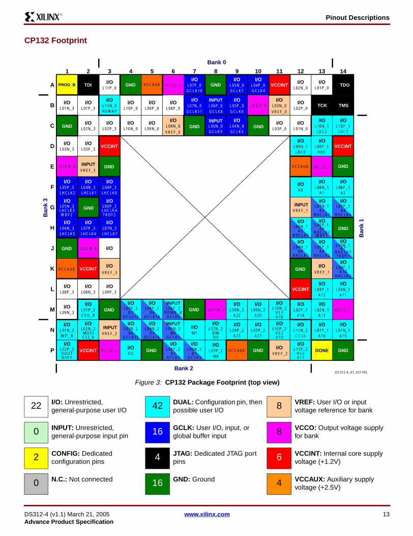
Pinout DescriptionsR
CP132 Footprint
Figure 3: CP132 Package Footprint (top view)
1 2 3 4 5 6 7 8 9 10 11 12 13 14
A PROG_B TDI TDO
TMSTCK
I/OL11P_0
I/OL07P_0
I/OL05N_0
I/OL04P_0 VCCINT
I/OL02N_0
I/OL01P_0
B I/OL01N_3
I/OL01P_3
I/OL11N_0HSWAP
I/OL10P_0
I/OL09P_0
I/OL08P_0
I/OL07N_0
INPUT
INPUT
L06P_0I/O
L05P_0I/O
L03N_0I/O
L02P_0
C I/OL02N_3
I/OL02P_3
I/OL10N_0
I/OL09N_0
I/OL08N_0 L06N_0
GCLK9 GCLK5
GCLK6
GCLK7 GCLK4GCLK10
GCLK11 GCLK8
I/OL04N_0
I/OL03P_0
I/OL01N_0
I/OL10N_1
I/OL10P_1
D I/OL03N_3
I/OL03P_3
VCCINTI/O
L09N_1LDC0
LDC1LDC2
I/OL09P_1
HDCVCCINT
E GND
GND
GND
GND
GND
GND GND
GND GND
GND
GND
GNDGNDGND
GND
GND
VCCAUX
VCCAUX
VCCAUX
VCCAUX
FI/O
L05P_3I/O
L04N_3I/O
L04P_3LHCLK0LHCLK1LHCLK2
LHCLK5 LHCLK6 LHCLK7
I/OA0
I/OL08N_1
A1
I/OL08P_1
A2
GI/O
L05N_3LHCLK3
I/OL06P_3LHCLK4TRDY2IRDY2
VREF_1
VREF_1
VREF_2
VREF_2
VREF_3
VREF_3
VREF_0
VREF_0
HI/O
L06N_3I/O
L07P_3I/O
L07N_3
J I/OI/O I/O
K VCCINTI/O I/O
L I/OL08P_3
I/OL08N_3
I/OL09P_3
VCCINTI/O
L03P_1A12
I/OL03N_1
A11
M I/OL09N_3
I/OL01P_2CSO_B
I/OL08N_2
A22
I/OL09N_2
A20
I/OL10N_2
VS1A18
I/OL02P_1
A14
I/OL02N_1
A13
NI/O
L01N_2INIT_B
I/OL02N_2MOSICSI_B
I/OM1
I/OL07N_2
DIND0
I/OL08P_2
A23
I/OL09P_2
A21
I/OL10P_2
VS2A19
I/OL11N_2CCLK
I/OL01P_1
A16
I/OL01N_1
A15
PI/O
L02P_2DOUTBUSY
VCCINT VCCO_2
VCCO_2 VCCO_1
VCCO_1
VCCO_0
VCCO_0
VCCO_3
VCCO_3
I/OD5
I/OL07P_2
M0
I/OI/O
L11P_2VS0A17
DONE
Bank 2
Bank 0
Ban
k 3
Ban
k 1
I/OL07P_1
4RHCLK6
L07N_1
RHCLK7A3
I/O
RHCLK5A5
L06N_1I/O
RHCLK4A6
L06P_1I/O
A
RHCLK3
L05N_1I/O
7A
RHCLK2A8
L05P_1
RHCLK1A9
L04N_1
RHCLK0A10
L04P_1I/O
I/OL06N_2
D1GCLK3
I/OL06P_2
D2GCLK2
L05N_2M2
GCLK1
INPUT
INPUT
INPUT
INPUT
INPUT
L05P_2RDWR_BGCLK0
I/OL04N_2
D3GCLK15
I/OL03N_2
D6GCLK13
I/OL04P_2
D4GCLK14
I/OL03P_2
D7GCLK12
IRDY1
TRDY1
DS312-4_07_031105
22 I/O: Unrestricted, general-purpose user I/O 42 DUAL: Configuration pin, then
possible user I/O 8 VREF: User I/O or input voltage reference for bank
0 INPUT: Unrestricted, general-purpose input pin 16 GCLK: User I/O, input, or
global buffer input 8 VCCO: Output voltage supply for bank
2 CONFIG: Dedicated configuration pins 4 JTAG: Dedicated JTAG port
pins 6 VCCINT: Internal core supply voltage (+1.2V)
0 N.C.: Not connected 16 GND: Ground 4 VCCAUX: Auxiliary supply voltage (+2.5V)
DS312-4 (v1.1) March 21, 2005 www.xilinx.com 13Advance Product Specification

Pinout DescriptionsR
TQ144: 144-lead Thin Quad Flat Package The XC3S100E and the XC3S250E FPGAs are available inthe 144-lead thin quad flat package, TQ144. Both devicesshare a common footprint for this package as shown inTable 12 and Figure 4.
Table 12 lists all the package pins. They are sorted by banknumber and then by pin name of the largest device. Pinsthat form a differential I/O pair appear together in the table.The table also shows the pin number for each pin and thepin type, as defined earlier.
The TQ144 package only supports 20 address output pinsin the Byte-wide Peripheral Interface (BPI) configuration
mode. In larger packages, there are 24 BPI address out-puts.
An electronic version of this package pinout table and foot-print diagram is available for download from the Xilinx website at http://www.xilinx.com/bvdocs/publications/s3e_pin.zip.
Pinout Table Table 12 shows the pinout for production Spartan-3EFPGAs in the VQ100 package. The XC3S100 engineeringsamples have a slightly different pinout, as described inTable 15.
Table 12: TQ144 Package Pinout
Bank XC3S100E Pin Name XC3S250E Pin Name TQ144 Pin Type
0 IO IO P132 I/O
0 IO/VREF_0 IO/VREF_0 P124 VREF
0 IO_L01N_0 IO_L01N_0 P113 I/O
0 IO_L01P_0 IO_L01P_0 P112 I/O
0 IO_L02N_0 IO_L02N_0 P117 I/O
0 IO_L02P_0 IO_L02P_0 P116 I/O
0 IO_L04N_0/GCLK5 IO_L04N_0/GCLK5 P123 GCLK
0 IO_L04P_0/GCLK4 IO_L04P_0/GCLK4 P122 GCLK
0 IO_L05N_0/GCLK7 IO_L05N_0/GCLK7 P126 GCLK
0 IO_L05P_0/GCLK6 IO_L05P_0/GCLK6 P125 GCLK
0 IO_L07N_0/GCLK11 IO_L07N_0/GCLK11 P131 GCLK
0 IO_L07P_0/GCLK10 IO_L07P_0/GCLK10 P130 GCLK
0 IO_L08N_0/VREF_0 IO_L08N_0/VREF_0 P135 VREF
0 IO_L08P_0 IO_L08P_0 P134 I/O
0 IO_L09N_0 IO_L09N_0 P140 I/O
0 IO_L09P_0 IO_L09P_0 P139 I/O
0 IO_L10N_0/HSWAP IO_L10N_0/HSWAP P143 DUAL
0 IO_L10P_0 IO_L10P_0 P142 I/O
0 IP IP P111 INPUT
0 IP IP P114 INPUT
0 IP IP P136 INPUT
0 IP IP P141 INPUT
0 IP_L03N_0 IP_L03N_0 P120 INPUT
0 IP_L03P_0 IP_L03P_0 P119 INPUT
0 IP_L06N_0/GCLK9 IP_L06N_0/GCLK9 P129 GCLK
0 IP_L06P_0/GCLK8 IP_L06P_0/GCLK8 P128 GCLK
14 www.xilinx.com DS312-4 (v1.1) March 21, 2005Advance Product Specification

Pinout DescriptionsR
0 VCCO_0 VCCO_0 P121 VCCO
0 VCCO_0 VCCO_0 P138 VCCO
1 IO/A0 IO/A0 P98 DUAL
1 IO/VREF_1 IO/VREF_1 P83 VREF
1 IO_L01N_1/A15 IO_L01N_1/A15 P75 DUAL
1 IO_L01P_1/A16 IO_L01P_1/A16 P74 DUAL
1 IO_L02N_1/A13 IO_L02N_1/A13 P77 DUAL
1 IO_L02P_1/A14 IO_L02P_1/A14 P76 DUAL
1 IO_L03N_1/A11 IO_L03N_1/A11 P82 DUAL
1 IO_L03P_1/A12 IO_L03P_1/A12 P81 DUAL
1 IO_L04N_1/A9/RHCLK1 IO_L04N_1/A9/RHCLK1 P86 RHCLK/DUAL
1 IO_L04P_1/A10/RHCLK0 IO_L04P_1/A10/RHCLK0 P85 RHCLK/DUAL
1 IO_L05N_1/A7/RHCLK3/TRDY1 IO_L05N_1/A7/RHCLK3 P88 RHCLK/DUAL
1 IO_L05P_1/A8/RHCLK2 IO_L05P_1/A8/RHCLK2 P87 RHCLK/DUAL
1 IO_L06N_1/A5/RHCLK5 IO_L06N_1/A5/RHCLK5 P92 RHCLK/DUAL
1 IO_L06P_1/A6/RHCLK4/IRDY1 IO_L06P_1/A6/RHCLK4 P91 RHCLK/DUAL
1 IO_L07N_1/A3/RHCLK7 IO_L07N_1/A3/RHCLK7 P94 RHCLK/DUAL
1 IO_L07P_1/A4/RHCLK6 IO_L07P_1/A4/RHCLK6 P93 RHCLK/DUAL
1 IO_L08N_1/A1 IO_L08N_1/A1 P97 DUAL
1 IO_L08P_1/A2 IO_L08P_1/A2 P96 DUAL
1 IO_L09N_1/LDC0 IO_L09N_1/LDC0 P104 DUAL
1 IO_L09P_1/HDC IO_L09P_1/HDC P103 DUAL
1 IO_L10N_1/LDC2 IO_L10N_1/LDC2 P106 DUAL
1 IO_L10P_1/LDC1 IO_L10P_1/LDC1 P105 DUAL
1 IP IP P78 INPUT
1 IP IP P84 INPUT
1 IP IP P89 INPUT
1 IP IP P101 INPUT
1 IP IP P107 INPUT
1 IP/VREF_1 IP/VREF_1 P95 VREF
1 VCCO_1 VCCO_1 P79 VCCO
1 VCCO_1 VCCO_1 P100 VCCO
2 IO/D5 IO/D5 P52 DUAL
2 IO/M1 IO/M1 P60 DUAL
2 IP/VREF_2 IO/VREF_2 P66 100E: VREF(INPUT)
250E: VREF(I/O)
Table 12: TQ144 Package Pinout (Continued)
Bank XC3S100E Pin Name XC3S250E Pin Name TQ144 Pin Type
DS312-4 (v1.1) March 21, 2005 www.xilinx.com 15Advance Product Specification

Pinout DescriptionsR
2 IO_L01N_2/INIT_B IO_L01N_2/INIT_B P40 DUAL
2 IO_L01P_2/CSO_B IO_L01P_2/CSO_B P39 DUAL
2 IO_L02N_2/MOSI/CSI_B IO_L02N_2/MOSI/CSI_B P44 DUAL
2 IO_L02P_2/DOUT/BUSY IO_L02P_2/DOUT/BUSY P43 DUAL
2 IO_L04N_2/D6/GCLK13 IO_L04N_2/D6/GCLK13 P51 DUAL/GCLK
2 IO_L04P_2/D7/GCLK12 IO_L04P_2/D7/GCLK12 P50 DUAL/GCLK
2 IO_L05N_2/D3/GCLK15 IO_L05N_2/D3/GCLK15 P54 DUAL/GCLK
2 IO_L05P_2/D4/GCLK14 IO_L05P_2/D4/GCLK14 P53 DUAL/GCLK
2 IO_L07N_2/D1/GCLK3 IO_L07N_2/D1/GCLK3 P59 DUAL/GCLK
2 IO_L07P_2/D2/GCLK2 IO_L07P_2/D2/GCLK2 P58 DUAL/GCLK
2 IO_L08N_2/DIN/D0 IO_L08N_2/DIN/D0 P63 DUAL
2 IO_L08P_2/M0 IO_L08P_2/M0 P62 DUAL
2 IO_L09N_2/VS1/A18 IO_L09N_2/VS1/A18 P68 DUAL
2 IO_L09P_2/VS2/A19 IO_L09P_2/VS2/A19 P67 DUAL
2 IO_L10N_2/CCLK IO_L10N_2/CCLK P71 DUAL
2 IO_L10P_2/VS0/A17 IO_L10P_2/VS0/A17 P70 DUAL
2 IP IP P38 INPUT
2 IP IP P41 INPUT
2 IP IP P69 INPUT
2 IP_L03N_2/VREF_2 IP_L03N_2/VREF_2 P48 VREF
2 IP_L03P_2 IP_L03P_2 P47 INPUT
2 IP_L06N_2/M2/GCLK1 IP_L06N_2/M2/GCLK1 P57 DUAL/GCLK
2 IP_L06P_2/RDWR_B/GCLK0 IP_L06P_2/RDWR_B/GCLK0 P56 DUAL/GCLK
2 VCCO_2 VCCO_2 P42 VCCO
2 VCCO_2 VCCO_2 P49 VCCO
2 VCCO_2 VCCO_2 P64 VCCO
3 IP/VREF_3 IO/VREF_3 P31 100E: VREF(INPUT)
250E: VREF(I/O)
3 IO_L01N_3 IO_L01N_3 P3 I/O
3 IO_L01P_3 IO_L01P_3 P2 I/O
3 IO_L02N_3/VREF_3 IO_L02N_3/VREF_3 P5 VREF
3 IO_L02P_3 IO_L02P_3 P4 I/O
3 IO_L03N_3 IO_L03N_3 P8 I/O
3 IO_L03P_3 IO_L03P_3 P7 I/O
3 IO_L04N_3/LHCLK1 IO_L04N_3/LHCLK1 P15 LHCLK
3 IO_L04P_3/LHCLK0 IO_L04P_3/LHCLK0 P14 LHCLK
Table 12: TQ144 Package Pinout (Continued)
Bank XC3S100E Pin Name XC3S250E Pin Name TQ144 Pin Type
16 www.xilinx.com DS312-4 (v1.1) March 21, 2005Advance Product Specification

Pinout DescriptionsR
3 IO_L05N_3/LHCLK3/IRDY2 IO_L05N_3/LHCLK3 P17 LHCLK
3 IO_L05P_3/LHCLK2 IO_L05P_3/LHCLK2 P16 LHCLK
3 IO_L06N_3/LHCLK5 IO_L06N_3/LHCLK5 P21 LHCLK
3 IO_L06P_3/LHCLK4/TRDY2 IO_L06P_3/LHCLK4 P20 LHCLK
3 IO_L07N_3/LHCLK7 IO_L07N_3/LHCLK7 P23 LHCLK
3 IO_L07P_3/LHCLK6 IO_L07P_3/LHCLK6 P22 LHCLK
3 IO_L08N_3 IO_L08N_3 P26 I/O
3 IO_L08P_3 IO_L08P_3 P25 I/O
3 IO_L09N_3 IO_L09N_3 P33 I/O
3 IO_L09P_3 IO_L09P_3 P32 I/O
3 IO_L10N_3 IO_L10N_3 P35 I/O
3 IO_L10P_3 IO_L10P_3 P34 I/O
3 IP IP P6 INPUT
3 IO IP P10 100E: I/O
250E: INPUT
3 IP IP P18 INPUT
3 IP IP P24 INPUT
3 IO IP P29 100E: I/O
250E: INPUT
3 IP IP P36 INPUT
3 IP/VREF_3 IP/VREF_3 P12 VREF
3 VCCO_3 VCCO_3 P13 VCCO
3 VCCO_3 VCCO_3 P28 VCCO
GND GND GND P11 GND
GND GND GND P19 GND
GND GND GND P27 GND
GND GND GND P37 GND
GND GND GND P46 GND
GND GND GND P55 GND
GND GND GND P61 GND
GND GND GND P73 GND
GND GND GND P90 GND
GND GND GND P99 GND
GND GND GND P118 GND
GND GND GND P127 GND
GND GND GND P133 GND
Table 12: TQ144 Package Pinout (Continued)
Bank XC3S100E Pin Name XC3S250E Pin Name TQ144 Pin Type
DS312-4 (v1.1) March 21, 2005 www.xilinx.com 17Advance Product Specification

Pinout DescriptionsR
User I/Os by Bank Table 13 and Table 14 indicate how the 108 availableuser-I/O pins are distributed between the four I/O banks onthe TQ144 package.
VCCAUX DONE DONE P72 CONFIG
VCCAUX PROG_B PROG_B P1 CONFIG
VCCAUX TCK TCK P110 JTAG
VCCAUX TDI TDI P144 JTAG
VCCAUX TDO TDO P109 JTAG
VCCAUX TMS TMS P108 JTAG
VCCAUX VCCAUX VCCAUX P30 VCCAUX
VCCAUX VCCAUX VCCAUX P65 VCCAUX
VCCAUX VCCAUX VCCAUX P102 VCCAUX
VCCAUX VCCAUX VCCAUX P137 VCCAUX
VCCINT VCCINT VCCINT P9 VCCINT
VCCINT VCCINT VCCINT P45 VCCINT
VCCINT VCCINT VCCINT P80 VCCINT
VCCINT VCCINT VCCINT P115 VCCINT
Table 12: TQ144 Package Pinout (Continued)
Bank XC3S100E Pin Name XC3S250E Pin Name TQ144 Pin Type
Table 13: User I/Os Per Bank for the XC3S100E in the TQ144 Package
Package Edge I/O Bank
Maximum I/O
All Possible I/O Pins by Type
I/O INPUT DUAL VREF GCLK
Top 0 26 9 6 1 2 8
Right 1 28 0 5 21 2 0
Bottom 2 26 0 4 20 2 0
Left 3 28 13 4 0 3 8
TOTAL 108 22 19 42 9 16
Table 14: User I/Os Per Bank for the XC3S250E in TQ144 Package
Package Edge I/O Bank
Maximum I/O
All Possible I/O Pins by Type
I/O INPUT DUAL VREF GCLK
Top 0 26 9 6 1 2 8
Right 1 28 0 5 21 2 0
Bottom 2 26 0 4 20 2 0
Left 3 28 11 6 0 3 8
TOTAL 108 20 21 42 9 16
18 www.xilinx.com DS312-4 (v1.1) March 21, 2005Advance Product Specification

Pinout DescriptionsR
Footprint Migration DifferencesTable 15 summarizes any footprint and functionality differ-ences between the XC3S100E and the XC3S250E FPGAsthat may affect easy migration between devices. There arefour such pins. All other pins not listed in Table 15 uncondi-tionally migrate between Spartan-3E devices available inthe TQ144 package.
The arrows indicate the direction for easy migration. Forexample, a left-facing arrow indicates that the pin on theXC3S250E unconditionally migrates to the pin on theXC3S100E. It may be possible to migrate the oppositedirection depending on the I/O configuration. For example,an I/O pin (Type = I/O) can migrate to an input-only pin(Type = INPUT) if the I/O pin is configured as an input.
The pinout changed slightly between the XC3S100E engi-neering samples and the production devices, as shown inTable 16. In the engineering samples, the mode select pinsM1 and M0 overlap with two global clock inputs feeding thebottom edge global buffers and DCMs. In the productiondevices, the mode pins are swapped with parallel modedata pins, D1 and D2. This way, these two mode pins do notinterfere with global clock inputs.
Table 15: TQ144 Footprint Migration Differences
TQ144 Pin Bank XC3S100E Type Migration XC3S250E Type
P10 3 I/O INPUT
P29 3 I/O INPUT
P31 3 VREF(INPUT) VREF(I/O)
P66 2 VREF(INPUT) VREF(I/O)
DIFFERENCES 4
Legend:
This pin can unconditionally migrate from the device on the left to the device on the right. Migration in the other direction may be
possible depending on how the pin is configured for the device on the right.
This pin can unconditionally migrate from the device on the right to the device on the left. Migration in the other direction may be
possible depending on how the pin is configured for the device on the left.
Table 16: XC3S100E Pinout Changes between Production Devices and Engineering Samples
TQ144 Pin
XC3S100E Production
Devices
XC3S100E Engineering
Samples
P58 D2/GCLK2 M1/GCLK2
P59 D1/GCLK3 M0/GCLK3
P60 M1 D2
P62 M0 D1
DS312-4 (v1.1) March 21, 2005 www.xilinx.com 19Advance Product Specification

Pinout DescriptionsR
TQ144 FootprintNote pin 1 indicator in top-left corner and logo orientation.Double arrows ( ) indicates a pinout migration difference
between the XC3S100E and XC3S250E. Engineering sam-ple footprint is slightly different.
Figure 4: TQ144 Package Production Footprint (top view)
TD
I
IO_L
10N
_0/H
SW
AP
IO_L
10P
_0
IP IO_L
09N
_0
IO_L
09P
_0
VC
CO
_0
VC
CA
UX
IP IO_L
08N
_0/V
RE
F_0
IO_L
08P
_0
GN
D
IO IO_L
07N
_0/G
CLK
11
IO_L
07P
_0/G
CLK
10
IP_L
06N
_0/G
CLK
9
IP_L
06P
_0/G
CLK
8
GN
D
IO_L
05N
_0/G
CLK
7
IO_L
05P
_0/G
CLK
6
IO/V
RE
F_0
IO_L
04N
_0/G
CLK
5
IO_L
04P
_0/G
CLK
4
VC
CO
_0
IP_L
03N
_0
IP_L
03P
_0
GN
D
IO_L
02N
_0
IO_L
02P
_0
VC
CIN
T
IP IO_L
01N
_0
IO_L
01P
_0
IP TC
K
TD
O
144
143
142
141
140
139
138
137
136
135
134
133
132
131
130
129
128
127
126
125
124
123
122
121
120
119
118
117
116
115
114
113
112
111
110
109
PROG_B 1 108 TMSIO_L01P_3 2 107 IP
IO_L01N_3 3 106 IO_L10N_1/LDC2
IO_L02P_3 4 105 IO_L10P_1/LDC1
IO_L02N_3/VREF_3 5 104 IO_L09N_1/LDC0
IP 6 103 IO_L09P_1/HDC
IO_L03P_3 7 102 VCCAUX
IO_L03N_3 8 101 IP
VCCINT 9 100 VCCO_1( ) IP 10 99 GND
GND 11 98 IO/A0
IP/VREF_3 12 97 IO_L08N_1/A1
VCCO_3 13 96 IO_L08P_1/A2
IO_L04P_3/LHCLK0 14 95 IP/VREF_1
IO_L04N_3/LHCLK1 15 IO_L07N_1/A3/RHCLK7
IO_L05P_3/LHCLK2 16 IO_L07P_1/A4/RHCLK6
IO_L05N_3/LHCLK3 17 IO_L06N_1/A5/RHCLK5
IP 18 IO_L06P_1/A6/RHCLK4
GND 19 90 GND
IO_L06P_3/LHCLK4 20 89 IP
IO_L06N_3/LHCLK5 21 IO_L05N_1/A7/RHCLK3
IO_L07P_3/LHCLK6 22 IO_L05P_1/A8/RHCLK2
IO_L07N_3/LHCLK7 23 IO_L04N_1/A9/RHCLK1
IP 24 IO_L04P_1/A10/RHCLK0
IO_L08P_3 25 84 IP
IO_L08N_3 26 83 IO/VREF_1
GND 27 82 IO_L03N_1/A11
VCCO_3 28 81 IO_L03P_1/A12( ) IP 29 80 VCCINT
VCCAUX 30 79 VCCO_1( ) IO/VREF_3 31 78 IP
IO_L09P_3 32 77 IO_L02N_1/A13
IO_L09N_3 33 76 IO_L02P_1/A14
IO_L10P_3 34 75 IO_L01N_1/A15
IO_L10N_3 35 74 IO_L01P_1/A16IP 36 73 GND
37 38 39 40 41 42 43 44 45 46 47 48 49 52 55 60 61 62 63 64 65 66 67 68 69 70 71 72
GN
D IP
IO_L
01P
_2/C
SO
_B
IO_L
01N
_2/IN
IT_B IP
VC
CO
_2
IO_L
02P
_2/D
OU
T/B
US
Y
IO_L
02N
_2/M
OS
I/CS
I_B
VC
CIN
T
GN
D
IP_L
03P
_2
IP_L
03N
_2/V
RE
F_2
VC
CO
_2
IO_L
04P
_2/D
7/G
CLK
12
IO_L
04N
_2/D
6/G
CLK
13
IO/D
5
IO_L
05P
_2/D
4/G
CLK
14
IO_L
05N
_2/D
3/G
CLK
15
GN
D
IP_L
06P
_2/R
DW
R_B
/GC
LK0
IP_L
06N
_2/M
2/G
CLK
1
IO_L
07P
_2/D
2/G
CLK
2
IO_L
07N
_2/D
1/G
CLK
3
IO/M
1
GN
D
IO_L
08P
_2/M
0
IO_L
08N
_2/D
IN/D
0
VC
CO
_2
VC
CA
UX
()
IO/V
RE
F_2
IO_L
09P
_2/V
S2/
A19
IO_L
09N
_2/V
S1/
A18 IP
IO_L
10P
_2/V
S0/
A17
IO_L
10N
_2/C
CLK
DO
NE
Bank 0
Ban
k3
Ban
k1
Bank 2
50 51 53 54 56 57 58 59
85
86
87
88
91
92
93
94
DS312-4_01_030705
20 I/O: Unrestricted, general-purpose user I/O 42 DUAL: Configuration pin, then
possible user I/O 9 VREF: User I/O or input voltage reference for bank
21 INPUT: Unrestricted, general-purpose input pin 16 GCLK: User I/O, input, or
global buffer input 9 VCCO: Output voltage supply for bank
2 CONFIG: Dedicated configuration pins 4 JTAG: Dedicated JTAG port
pins 4 VCCINT: Internal core supply voltage (+1.2V)
0 N.C.: Not connected 13 GND: Ground 4 VCCAUX: Auxiliary supply voltage (+2.5V)
20 www.xilinx.com DS312-4 (v1.1) March 21, 2005Advance Product Specification

Pinout DescriptionsR
PQ208: 208-pin Plastic Quad Flat PackageThe 208-pin plastic quad flat package, PQ208, supports twodifferent Spartan-3E FPGAs, including the XC3S250E andthe XC3S500E.
Table 17 lists all the PQ208 package pins. They are sortedby bank number and then by pin name. Pairs of pins thatform a differential I/O pair appear together in the table. Thetable also shows the pin number for each pin and the pintype, as defined earlier.
An electronic version of this package pinout table and foot-print diagram is available for download from the Xilinx web-site at http://www.xilinx.com/bvdocs/publications/s3e_pin.zip.
Pinout Table
Table 17: PQ208 Package Pinout
Bank
XC3S250EXC3S500EPin Name
PQ208 Pin Type
0 IO P187 I/O
0 IO/VREF_0 P179 VREF
0 IO_L01N_0 P161 I/O
0 IO_L01P_0 P160 I/O
0 IO_L02N_0/VREF_0 P163 VREF
0 IO_L02P_0 P162 I/O
0 IO_L03N_0 P165 I/O
0 IO_L03P_0 P164 I/O
0 IO_L04N_0/VREF_0 P168 VREF
0 IO_L04P_0 P167 I/O
0 IO_L05N_0 P172 I/O
0 IO_L05P_0 P171 I/O
0 IO_L07N_0/GCLK5 P178 GCLK
0 IO_L07P_0/GCLK4 P177 GCLK
0 IO_L08N_0/GCLK7 P181 GCLK
0 IO_L08P_0/GCLK6 P180 GCLK
0 IO_L10N_0/GCLK11 P186 GCLK
0 IO_L10P_0/GCLK10 P185 GCLK
0 IO_L11N_0 P190 I/O
0 IO_L11P_0 P189 I/O
0 IO_L12N_0/VREF_0 P193 VREF
0 IO_L12P_0 P192 I/O
0 IO_L13N_0 P197 I/O
0 IO_L13P_0 P196 I/O
0 IO_L14N_0/VREF_0 P200 VREF
0 IO_L14P_0 P199 I/O
0 IO_L15N_0 P203 I/O
0 IO_L15P_0 P202 I/O
0 IO_L16N_0/HSWAP P206 DUAL
0 IO_L16P_0 P205 I/O
0 IP P159 INPUT
0 IP P169 INPUT
0 IP P194 INPUT
0 IP P204 INPUT
0 IP_L06N_0 P175 INPUT
0 IP_L06P_0 P174 INPUT
0 IP_L09N_0/GCLK9 P184 GCLK
0 IP_L09P_0/GCLK8 P183 GCLK
0 VCCO_0 P176 VCCO
0 VCCO_0 P191 VCCO
0 VCCO_0 P201 VCCO
1 IO_L01N_1/A15 P107 DUAL
1 IO_L01P_1/A16 P106 DUAL
1 IO_L02N_1/A13 P109 DUAL
1 IO_L02P_1/A14 P108 DUAL
1 IO_L03N_1/VREF_1 P113 VREF
1 IO_L03P_1 P112 I/O
1 IO_L04N_1 P116 I/O
1 IO_L04P_1 P115 I/O
1 IO_L05N_1/A11 P120 DUAL
1 IO_L05P_1/A12 P119 DUAL
1 IO_L06N_1/VREF_1 P123 VREF
1 IO_L06P_1 P122 I/O
1 IO_L07N_1/A9/RHCLK1 P127 RHCLK/DUAL
1 IO_L07P_1/A10/RHCLK0 P126 RHCLK/DUAL
1 IO_L08N_1/A7/RHCLK3 P129 RHCLK/DUAL
1 IO_L08P_1/A8/RHCLK2 P128 RHCLK/DUAL
Table 17: PQ208 Package Pinout
Bank
XC3S250EXC3S500EPin Name
PQ208 Pin Type
DS312-4 (v1.1) March 21, 2005 www.xilinx.com 21Advance Product Specification

Pinout DescriptionsR
1 IO_L09N_1/A5/RHCLK5 P133 RHCLK/DUAL
1 IO_L09P_1/A6/RHCLK4 P132 RHCLK/DUAL
1 IO_L10N_1/A3/RHCLK7 P135 RHCLK/DUAL
1 IO_L10P_1/A4/RHCLK6 P134 RHCLK/DUAL
1 IO_L11N_1/A1 P138 DUAL
1 IO_L11P_1/A2 P137 DUAL
1 IO_L12N_1/A0 P140 DUAL
1 IO_L12P_1 P139 I/O
1 IO_L13N_1 P145 I/O
1 IO_L13P_1 P144 I/O
1 IO_L14N_1 P147 I/O
1 IO_L14P_1 P146 I/O
1 IO_L15N_1/LDC0 P151 DUAL
1 IO_L15P_1/HDC P150 DUAL
1 IO_L16N_1/LDC2 P153 DUAL
1 IO_L16P_1/LDC1 P152 DUAL
1 IP P110 INPUT
1 IP P118 INPUT
1 IP P124 INPUT
1 IP P130 INPUT
1 IP P142 INPUT
1 IP P148 INPUT
1 IP P154 INPUT
1 IP/VREF_1 P136 VREF
1 VCCO_1 P114 VCCO
1 VCCO_1 P125 VCCO
1 VCCO_1 P143 VCCO
2 IO/D5 P76 DUAL
2 IO/M1 P84 DUAL
2 IO/VREF_2 P98 VREF
2 IO_L01N_2/INIT_B P56 DUAL
2 IO_L01P_2/CSO_B P55 DUAL
2 IO_L03N_2/MOSI/CSI_B P61 DUAL
2 IO_L03P_2/DOUT/BUSY P60 DUAL
Table 17: PQ208 Package Pinout
Bank
XC3S250EXC3S500EPin Name
PQ208 Pin Type
2 IO_L04N_2 P63 I/O
2 IO_L04P_2 P62 I/O
2 IO_L05N_2 P65 I/O
2 IO_L05P_2 P64 I/O
2 IO_L06N_2 P69 I/O
2 IO_L06P_2 P68 I/O
2 IO_L08N_2/D6/GCLK13 P75 DUAL/GCLK
2 IO_L08P_2/D7/GCLK12 P74 DUAL/GCLK
2 IO_L09N_2/D3/GCLK15 P78 DUAL/GCLK
2 IO_L09P_2/D4/GCLK14 P77 DUAL/GCLK
2 IO_L11N_2/D1/GCLK3 P83 DUAL/GCLK
2 IO_L11P_2/D2/GCLK2 P82 DUAL/GCLK
2 IO_L12N_2/DIN/D0 P87 DUAL
2 IO_L12P_2/M0 P86 DUAL
2 IO_L13N_2 P90 I/O
2 IO_L13P_2 P89 I/O
2 IO_L14N_2/A22 P94 DUAL
2 IO_L14P_2/A23 P93 DUAL
2 IO_L15N_2/A20 P97 DUAL
2 IO_L15P_2/A21 P96 DUAL
2 IO_L16N_2/VS1/A18 P100 DUAL
2 IO_L16P_2/VS2/A19 P99 DUAL
2 IO_L17N_2/CCLK P103 DUAL
2 IO_L17P_2/VS0/A17 P102 DUAL
2 IP P54 INPUT
2 IP P91 INPUT
2 IP P101 INPUT
2 IP_L02N_2 P58 INPUT
2 IP_L02P_2 P57 INPUT
2 IP_L07N_2/VREF_2 P72 VREF
2 IP_L07P_2 P71 INPUT
2 IP_L10N_2/M2/GCLK1 P81 DUAL/GCLK
2 IP_L10P_2/RDWR_B/GCLK0
P80 DUAL/GCLK
2 VCCO_2 P59 VCCO
Table 17: PQ208 Package Pinout
Bank
XC3S250EXC3S500EPin Name
PQ208 Pin Type
22 www.xilinx.com DS312-4 (v1.1) March 21, 2005Advance Product Specification

Pinout DescriptionsR
2 VCCO_2 P73 VCCO
2 VCCO_2 P88 VCCO
3 IO/VREF_3 P45 VREF
3 IO_L01N_3 P3 I/O
3 IO_L01P_3 P2 I/O
3 IO_L02N_3/VREF_3 P5 VREF
3 IO_L02P_3 P4 I/O
3 IO_L03N_3 P9 I/O
3 IO_L03P_3 P8 I/O
3 IO_L04N_3 P12 I/O
3 IO_L04P_3 P11 I/O
3 IO_L05N_3 P16 I/O
3 IO_L05P_3 P15 I/O
3 IO_L06N_3 P19 I/O
3 IO_L06P_3 P18 I/O
3 IO_L07N_3/LHCLK1 P23 LHCLK
3 IO_L07P_3/LHCLK0 P22 LHCLK
3 IO_L08N_3/LHCLK3 P25 LHCLK
3 IO_L08P_3/LHCLK2 P24 LHCLK
3 IO_L09N_3/LHCLK5 P29 LHCLK
3 IO_L09P_3/LHCLK4 P28 LHCLK
3 IO_L10N_3/LHCLK7 P31 LHCLK
3 IO_L10P_3/LHCLK6 P30 LHCLK
3 IO_L11N_3 P34 I/O
3 IO_L11P_3 P33 I/O
3 IO_L12N_3 P36 I/O
3 IO_L12P_3 P35 I/O
3 IO_L13N_3 P40 I/O
3 IO_L13P_3 P39 I/O
3 IO_L14N_3 P42 I/O
3 IO_L14P_3 P41 I/O
3 IO_L15N_3 P48 I/O
3 IO_L15P_3 P47 I/O
3 IO_L16N_3 P50 I/O
Table 17: PQ208 Package Pinout
Bank
XC3S250EXC3S500EPin Name
PQ208 Pin Type
3 IO_L16P_3 P49 I/O
3 IP P6 INPUT
3 IP P14 INPUT
3 IP P26 INPUT
3 IP P32 INPUT
3 IP P43 INPUT
3 IP P51 INPUT
3 IP/VREF_3 P20 VREF
3 VCCO_3 P21 VCCO
3 VCCO_3 P38 VCCO
3 VCCO_3 P46 VCCO
GND GND P10 GND
GND GND P17 GND
GND GND P27 GND
GND GND P37 GND
GND GND P52 GND
GND GND P53 GND
GND GND P70 GND
GND GND P79 GND
GND GND P85 GND
GND GND P95 GND
GND GND P105 GND
GND GND P121 GND
GND GND P131 GND
GND GND P141 GND
GND GND P156 GND
GND GND P173 GND
GND GND P182 GND
GND GND P188 GND
GND GND P198 GND
GND GND P208 GND
VCCAUX DONE P104 CONFIG
VCCAUX PROG_B P1 CONFIG
VCCAUX TCK P158 JTAG
Table 17: PQ208 Package Pinout
Bank
XC3S250EXC3S500EPin Name
PQ208 Pin Type
DS312-4 (v1.1) March 21, 2005 www.xilinx.com 23Advance Product Specification
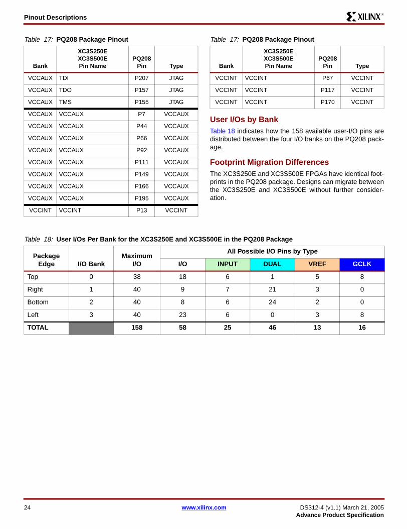
Pinout DescriptionsR
User I/Os by Bank Table 18 indicates how the 158 available user-I/O pins aredistributed between the four I/O banks on the PQ208 pack-age.
Footprint Migration DifferencesThe XC3S250E and XC3S500E FPGAs have identical foot-prints in the PQ208 package. Designs can migrate betweenthe XC3S250E and XC3S500E without further consider-ation.
VCCAUX TDI P207 JTAG
VCCAUX TDO P157 JTAG
VCCAUX TMS P155 JTAG
VCCAUX VCCAUX P7 VCCAUX
VCCAUX VCCAUX P44 VCCAUX
VCCAUX VCCAUX P66 VCCAUX
VCCAUX VCCAUX P92 VCCAUX
VCCAUX VCCAUX P111 VCCAUX
VCCAUX VCCAUX P149 VCCAUX
VCCAUX VCCAUX P166 VCCAUX
VCCAUX VCCAUX P195 VCCAUX
VCCINT VCCINT P13 VCCINT
Table 17: PQ208 Package Pinout
Bank
XC3S250EXC3S500EPin Name
PQ208 Pin Type
VCCINT VCCINT P67 VCCINT
VCCINT VCCINT P117 VCCINT
VCCINT VCCINT P170 VCCINT
Table 17: PQ208 Package Pinout
Bank
XC3S250EXC3S500EPin Name
PQ208 Pin Type
Table 18: User I/Os Per Bank for the XC3S250E and XC3S500E in the PQ208 Package
Package Edge I/O Bank
Maximum I/O
All Possible I/O Pins by Type
I/O INPUT DUAL VREF GCLK
Top 0 38 18 6 1 5 8
Right 1 40 9 7 21 3 0
Bottom 2 40 8 6 24 2 0
Left 3 40 23 6 0 3 8
TOTAL 158 58 25 46 13 16
24 www.xilinx.com DS312-4 (v1.1) March 21, 2005Advance Product Specification

Pinout DescriptionsR
PQ208 Footprint (Left)
Figure 5: PQ208 Footprint (Left)
GN
D
TD
I
IO_L
16N
_0/H
SW
AP
IO_L
16P
_0
IP IO_L
15N
_0
IO_L
15P
_0
VC
CO
_0
IO_L
14N
_0/V
RE
F_0
IO_L
14P
_0
GN
D
IO_L
13N
_0
IO_L
13P
_0
VC
CA
UX
IP IO_L
12N
_0/V
RE
F_0
IO_L
12P
_0
VC
CO
_0
IO_L
11N
_0
IO_L
11P
_0
GN
D
IO IO_L
10N
_0/G
CLK
11
IO_L
10P
_0/G
CLK
10
IP_L
09N
_0/G
CLK
9
IP_L
09P
_0/G
CLK
8
GN
D
208
207
206
205
204
203
202
201
200
199
198
197
196
195
194
193
192
191
190
189
188
187
186
185
184
183
182
PROG_B 1IO_L01P_3 2
IO_L01N_3 3IO_L02P_3 4
IO_L02N_3/VREF_3 5IP 6
VCCAUX 7IO_L03P_3 8
IO_L03N_3 9GND 10
IO_L04P_3 11IO_L04N_3 12
VCCINT 13IP 14
IO_L05P_3 15IO_L05N_3 16
GND 17IO_L06P_3 18
IO_L06N_3 19IP/VREF_3 20
VCCO_3 21IO_L07P_3/LHCLK0 22
IO_L07N_3/LHCLK1 23IO_L08P_3/LHCLK2 24
IO_L08N_3/LHCLK3 25IP 26
GND 27IO_L09P_3/LHCLK4 28
IO_L09N_3/LHCLK5 29IO_L10P_3/LHCLK6 30
IO_L10N_3/LHCLK7 31IP 32
IO_L11P_3 33IO_L11N_3 34
IO_L12P_3 35IO_L12N_3 36
GND 37VCCO_3 38
IO_L13P_3 39IO_L13N_3 40
IO_L14P_3 41IO_L14N_3 42
IP 43VCCAUX 44
IO/VREF_3 45VCCO_3 46
IO_L15P_3 47IO_L15N_3 48
IO_L16P_3 49IO_L16N_3 50
IP 51GND 52
53 54 55 56 57 58 59 60 61 62 63 64 65 66 67 68 69 70 71 72 73 76 79
GN
D IP
IO_L
01P
_2/C
SO
_B
IO_L
01N
_2/IN
IT_B
IP_L
02P
_2
IP_L
02N
_2
VC
CO
_2
IO_L
03P
_2/D
OU
T/B
US
Y
IO_L
03N
_2/M
OS
I/CS
I_B
IO_L
04P
_2
IO_L
04N
_2
IO_L
05P
_2
IO_L
05N
_2
VC
CA
UX
VC
CIN
T
IO_L
06P
_2
IO_L
06N
_2
GN
D
IP_L
07P
_2
IP_L
07N
_2/V
RE
F_2
VC
CO
_2
IO_L
08P
_2/D
7/G
CLK
12
IO_L
08N
_2/D
6/G
CLK
13
IO/D
5
IO_L
09P
_2/D
4/G
CLK
14
IO_L
09N
_2/D
3/G
CLK
15
GN
D
Bank 0
Ban
k3
Bank 2
74 75 77 78
DS312-4_03_030705
DS312-4 (v1.1) March 21, 2005 www.xilinx.com 25Advance Product Specification

Pinout DescriptionsR
PQ208 Footprint (Right)
Figure 6: PQ208 Footprint (Right)
IO_L
08N
_0/G
CLK
7
IO_L
08P
_0/G
CLK
6
IO/V
RE
F_0
IO_L
07N
_0/G
CLK
5
IO_L
07P
_0/G
CLK
4
VC
CO
_0
IP_L
06N
_0
IP_L
06P
_0
GN
D
IO_L
05N
_0
IO_L
05P
_0
VC
CIN
T
IP IO_L
04N
_0/V
RE
F_0
IO_L
04P
_0
VC
CA
UX
IO_L
03N
_0
IO_L
03P
_0
IO_L
02N
_0/V
RE
F_0
IO_L
02P
_0
IO_L
01N
_0
IO_L
01P
_0
IP TC
K
TD
O
181
180
179
178
177
176
175
174
173
172
171
170
169
168
167
166
165
164
163
162
161
160
159
158
157
156 GND155 TMS
154 IP153 IO_L16N_1/LDC2
152 IO_L16P_1/LDC1151 IO_L15N_1/LDC0
150 IO_L15P_1/HDC149 VCCAUX
148 IP147 IO_L14N_1
146 IO_L14P_1145 IO_L13N_1
144 IO_L13P_1143 VCCO_1
142 IP141 GND
140 IO_L12N_1/A0139 IO_L12P_1
138 IO_L11N_1/A1137 IO_L11P_1/A2
136 IP/VREF_1O_L10N_1/A3/RHCLK7
O_L10P_1/A4/RHCLK6O_L09N_1/A5/RHCLK5
O_L09P_1/A6/RHCLK4131 GND
130 IPO_L08N_1/A7/RHCLK3
O_L08P_1/A8/RHCLK2O_L07N_1/A9/RHCLK1
O_L07P_1/A10/RHCLK125 VCCO_1
124 IP123 IO_L06N_1/VREF_1
122 IO_L06P_1121 GND
120 IO_L05N_1/A11119 IO_L05P_1/A12
118 IP117 VCCINT
116 IO_L04N_1115 IO_L04P_1
114 VCCO_1113 IO_L03N_1/VREF_1
112 IO_L03P_1111 VCCAUX
110 IP109 IO_L02N_1/A13
108 IO_L02P_1/A14107 IO_L01N_1/A15
106 IO_L01P_1/A16105 GND
84 85 86 87 88 89 90 91 92 93 94 95 96 97 98 99 100
101
102
103
104
IP_L
10P
_2/R
DW
R_B
/GC
LK0
IP_L
10N
_2/M
2/G
CLK
1
IO_L
11P
_2/D
2/G
CLK
2
IO_L
11N
_2/D
1/G
CLK
3
IO/M
1
GN
D
IO_L
12P
_2/M
0
IO_L
12N
_2/D
IN/D
0
VC
CO
_2
IO_L
13P
_2
IO_L
13N
_2 IP
VC
CA
UX
IO_L
14P
_2/A
23
IO_L
14N
_2/A
22
GN
D
IO_L
15P
_2/A
21
IO_L
15N
_2/A
20
IO/V
RE
F_2
IO_L
16P
_2/V
S2/
A19
IO_L
16N
_2/V
S1/
A18 IP
IO_L
17P
_2/V
S0/
A17
IO_L
17N
_2/C
CLK
DO
NE
Ban
k1
Bank 0
Bank 2
80 81 82 83
126 I
127 I128 I
129 I
132 I
133 I134 I
135 I
DS312-4_04_030705
26 www.xilinx.com DS312-4 (v1.1) March 21, 2005Advance Product Specification

Pinout DescriptionsR
FT256: 256-ball Fine-pitch, Thin Ball Grid ArrayThe 256-lead fine-pitch, thin ball grid array package, FT256,supports three different Spartan-3E FPGAs, including theXC3S250E, the XC3S500E, and the XC3S1200E.
Table 19 lists all the package pins. They are sorted by banknumber and then by pin name of the largest device. Pinsthat form a differential I/O pair appear together in the table.The table also shows the pin number for each pin and thepin type, as defined earlier.
The highlighted rows indicate pinout differences betweenthe XC3S250E, the XC3S500E, and the XC3S1200EFPGAs. The XC3S250E has 18 unconnected balls, indi-cated as N.C. (No Connection) in Table 19 and with theblack diamond character ( ) in both Table 19 and inFigure 7.
If the table row is highlighted in tan, then this is an instancewhere an unconnected pin on the XC3S250E FPGA mapsto a VREF pin on the XC3S500E and XC3S1200E FPGA. Ifthe FPGA application uses an I/O standard that requires aVREF voltage reference, connect the highlighted pin to theVREF voltage supply, even though this does not actuallyconnect to the XC3S250E FPGA. This VREF connection onthe board allows future migration to the larger devices with-out modifying the printed-circuit board.
All other balls have nearly identical functionality on all threedevices. Table 23 summarizes the Spartan-3E footprintmigration differences for the FT256 package.
An electronic version of this package pinout table and foot-print diagram is available for download from the Xilinx website at http://www.xilinx.com/bvdocs/publications/s3e_pin.zip.
Pinout Table
Table 19: FT256 Package Pinout
Bank XC3S250E Pin Name XC3S500E Pin Name XC3S1200E Pin NameFT256 Ball Type
0 IO IO IO A7 I/O
0 IO IO IO A12 I/O
0 IO IO IO B4 I/O
0 IP IP IO B6 250E: INPUT
500E: INPUT
1200E: I/O
0 IP IP IO B10 250E: INPUT
500E: INPUT
1200E: I/O
0 IO/VREF_0 IO/VREF_0 IO/VREF_0 D9 VREF
0 IO_L01N_0 IO_L01N_0 IO_L01N_0 A14 I/O
0 IO_L01P_0 IO_L01P_0 IO_L01P_0 B14 I/O
0 IO_L03N_0/VREF_0 IO_L03N_0/VREF_0 IO_L03N_0/VREF_0 A13 VREF
0 IO_L03P_0 IO_L03P_0 IO_L03P_0 B13 I/O
0 IO_L04N_0 IO_L04N_0 IO_L04N_0 E11 I/O
0 IO_L04P_0 IO_L04P_0 IO_L04P_0 D11 I/O
0 IO_L05N_0/VREF_0 IO_L05N_0/VREF_0 IO_L05N_0/VREF_0 B11 VREF
0 IO_L05P_0 IO_L05P_0 IO_L05P_0 C11 I/O
0 IO_L06N_0 IO_L06N_0 IO_L06N_0 E10 I/O
0 IO_L06P_0 IO_L06P_0 IO_L06P_0 D10 I/O
0 IO_L08N_0/GCLK5 IO_L08N_0/GCLK5 IO_L08N_0/GCLK5 F9 GCLK
0 IO_L08P_0/GCLK4 IO_L08P_0/GCLK4 IO_L08P_0/GCLK4 E9 GCLK
0 IO_L09N_0/GCLK7 IO_L09N_0/GCLK7 IO_L09N_0/GCLK7 A9 GCLK
DS312-4 (v1.1) March 21, 2005 www.xilinx.com 27Advance Product Specification

Pinout DescriptionsR
0 IO_L09P_0/GCLK6 IO_L09P_0/GCLK6 IO_L09P_0/GCLK6 A10 GCLK
0 IO_L11N_0/GCLK11 IO_L11N_0/GCLK11 IO_L11N_0/GCLK11 D8 GCLK
0 IO_L11P_0/GCLK10 IO_L11P_0/GCLK10 IO_L11P_0/GCLK10 C8 GCLK
0 IO_L12N_0 IO_L12N_0 IO_L12N_0 F8 I/O
0 IO_L12P_0 IO_L12P_0 IO_L12P_0 E8 I/O
0 N.C. ( ) IO_L13N_0 IO_L13N_0 C7 250E: N.C.
500E: I/O
1200E: I/O
0 N.C. ( ) IO_L13P_0 IO_L13P_0 B7 250E: N.C.
500E: I/O
1200E: I/O
0 IO_L14N_0/VREF_0 IO_L14N_0/VREF_0 IO_L14N_0/VREF_0 D7 VREF
0 IO_L14P_0 IO_L14P_0 IO_L14P_0 E7 I/O
0 IO_L15N_0 IO_L15N_0 IO_L15N_0 D6 I/O
0 IO_L15P_0 IO_L15P_0 IO_L15P_0 C6 I/O
0 IO_L17N_0/VREF_0 IO_L17N_0/VREF_0 IO_L17N_0/VREF_0 A4 VREF
0 IO_L17P_0 IO_L17P_0 IO_L17P_0 A5 I/O
0 IO_L18N_0 IO_L18N_0 IO_L18N_0 C4 I/O
0 IO_L18P_0 IO_L18P_0 IO_L18P_0 C5 I/O
0 IO_L19N_0/HSWAP IO_L19N_0/HSWAP IO_L19N_0/HSWAP B3 DUAL
0 IO_L19P_0 IO_L19P_0 IO_L19P_0 C3 I/O
0 IP IP IP A3 INPUT
0 IP IP IP C13 INPUT
0 IP_L02N_0 IP_L02N_0 IP_L02N_0 C12 INPUT
0 IP_L02P_0 IP_L02P_0 IP_L02P_0 D12 INPUT
0 IP_L07N_0 IP_L07N_0 IP_L07N_0 C9 INPUT
0 IP_L07P_0 IP_L07P_0 IP_L07P_0 C10 INPUT
0 IP_L10N_0/GCLK9 IP_L10N_0/GCLK9 IP_L10N_0/GCLK9 B8 GCLK
0 IP_L10P_0/GCLK8 IP_L10P_0/GCLK8 IP_L10P_0/GCLK8 A8 GCLK
0 IP_L16N_0 IP_L16N_0 IP_L16N_0 E6 INPUT
0 IP_L16P_0 IP_L16P_0 IP_L16P_0 D5 INPUT
0 VCCO_0 VCCO_0 VCCO_0 B5 VCCO
0 VCCO_0 VCCO_0 VCCO_0 B12 VCCO
0 VCCO_0 VCCO_0 VCCO_0 F7 VCCO
0 VCCO_0 VCCO_0 VCCO_0 F10 VCCO
1 IO_L01N_1/A15 IO_L01N_1/A15 IO_L01N_1/A15 R15 DUAL
Table 19: FT256 Package Pinout (Continued)
Bank XC3S250E Pin Name XC3S500E Pin Name XC3S1200E Pin NameFT256 Ball Type
28 www.xilinx.com DS312-4 (v1.1) March 21, 2005Advance Product Specification

Pinout DescriptionsR
1 IO_L01P_1/A16 IO_L01P_1/A16 IO_L01P_1/A16 R16 DUAL
1 IO_L02N_1/A13 IO_L02N_1/A13 IO_L02N_1/A13 P15 DUAL
1 IO_L02P_1/A14 IO_L02P_1/A14 IO_L02P_1/A14 P16 DUAL
1 N.C. ( ) IO_L03N_1/VREF_1 IO_L03N_1/VREF_1 N15 250E: N.C.
500E: VREF
1200E: VREF
1 N.C. ( ) IO_L03P_1 IO_L03P_1 N14 250E: N.C.
500E: I/O
1200E: I/O
1 IO_L04N_1/VREF_1 IO_L04N_1/VREF_1 IO_L04N_1/VREF_1 M16 VREF
1 IO_L04P_1 IO_L04P_1 IO_L04P_1 N16 I/O
1 N.C. ( ) IO_L05N_1 IO_L05N_1 L13 250E: N.C.
500E: I/O
1200E: I/O
1 N.C. ( ) IO_L05P_1 IO_L05P_1 L12 250E: N.C.
500E: I/O
1200E: I/O
1 IO_L06N_1 IO_L06N_1 IO_L06N_1 L15 I/O
1 IO_L06P_1 IO_L06P_1 IO_L06P_1 L14 I/O
1 IO_L07N_1/A11 IO_L07N_1/A11 IO_L07N_1/A11 K12 DUAL
1 IO_L07P_1/A12 IO_L07P_1/A12 IO_L07P_1/A12 K13 DUAL
1 IO_L08N_1/VREF_1 IO_L08N_1/VREF_1 IO_L08N_1/VREF_1 K14 VREF
1 IO_L08P_1 IO_L08P_1 IO_L08P_1 K15 I/O
1 IO_L09N_1/A9/RHCLK1 IO_L09N_1/A9/RHCLK1 IO_L09N_1/A9/RHCLK1 J16 RHCLK/DUAL
1 IO_L09P_1/A10/RHCLK0 IO_L09P_1/A10/RHCLK0 IO_L09P_1/A10/RHCLK0 K16 RHCLK/DUAL
1 IO_L10N_1/A7/RHCLK3/TRDY1
IO_L10N_1/A7/RHCLK3/TRDY1
IO_L10N_1/A7/RHCLK3/TRDY1
J13 RHCLK/DUAL
1 IO_L10P_1/A8/RHCLK2 IO_L10P_1/A8/RHCLK2 IO_L10P_1/A8/RHCLK2 J14 RHCLK/DUAL
1 IO_L11N_1/A5/RHCLK5 IO_L11N_1/A5/RHCLK5 IO_L11N_1/A5/RHCLK5 H14 RHCLK/DUAL
1 IO_L11P_1/A6/RHCLK4/IRDY1
IO_L11P_1/A6/RHCLK4/IRDY1
IO_L11P_1/A6/RHCLK4/IRDY1
H15 RHCLK/DUAL
1 IO_L12N_1/A3/RHCLK7 IO_L12N_1/A3/RHCLK7 IO_L12N_1/A3/RHCLK7 H11 RHCLK/DUAL
1 IO_L12P_1/A4/RHCLK6 IO_L12P_1/A4/RHCLK6 IO_L12P_1/A4/RHCLK6 H12 RHCLK/DUAL
1 IO_L13N_1/A1 IO_L13N_1/A1 IO_L13N_1/A1 G16 DUAL
1 IO_L13P_1/A2 IO_L13P_1/A2 IO_L13P_1/A2 G15 DUAL
1 IO_L14N_1/A0 IO_L14N_1/A0 IO_L14N_1/A0 G14 DUAL
1 IO_L14P_1 IO_L14P_1 IO_L14P_1 G13 I/O
1 IO_L15N_1 IO_L15N_1 IO_L15N_1 F15 I/O
Table 19: FT256 Package Pinout (Continued)
Bank XC3S250E Pin Name XC3S500E Pin Name XC3S1200E Pin NameFT256 Ball Type
DS312-4 (v1.1) March 21, 2005 www.xilinx.com 29Advance Product Specification

Pinout DescriptionsR
1 IO_L15P_1 IO_L15P_1 IO_L15P_1 F14 I/O
1 IO_L16N_1 IO_L16N_1 IO_L16N_1 F12 I/O
1 IO_L16P_1 IO_L16P_1 IO_L16P_1 F13 I/O
1 N.C. ( ) IO_L17N_1 IO_L17N_1 E16 250E: N.C.
500E: I/O
1200E: I/O
1 N.C. ( ). IO_L17P_1 IO_L17P_1 E13 250E: N.C.
500E: I/O
1200E: I/O
1 IO_L18N_1/LDC0 IO_L18N_1/LDC0 IO_L18N_1/LDC0 D14 DUAL
1 IO_L18P_1/HDC IO_L18P_1/HDC IO_L18P_1/HDC D15 DUAL
1 IO_L19N_1/LDC2 IO_L19N_1/LDC2 IO_L19N_1/LDC2 C15 DUAL
1 IO_L19P_1/LDC1 IO_L19P_1/LDC1 IO_L19P_1/LDC1 C16 DUAL
1 IP IP IP B16 INPUT
1 IP IP IP E14 INPUT
1 IP IP IP G12 INPUT
1 IP IP IP H16 INPUT
1 IP IP IP J11 INPUT
1 IP IP IP J12 INPUT
1 IP IP IP M13 INPUT
1 IO IO IP M14 250E: I/O
500E: I/O
1200E: INPUT
1 IO/VREF_1 IP/VREF_1 IP/VREF_1 D16 250E: VREF(I/O)
500E: VREF(INPUT)
1200E: VREF(INPUT)
1 IP/VREF_1 IP/VREF_1 IP/VREF_1 H13 VREF
1 VCCO_1 VCCO_1 VCCO_1 E15 VCCO
1 VCCO_1 VCCO_1 VCCO_1 G11 VCCO
1 VCCO_1 VCCO_1 VCCO_1 K11 VCCO
1 VCCO_1 VCCO_1 VCCO_1 M15 VCCO
2 IP IP IO M7 250E: INPUT
500E: INPUT
1200E: I/O
2 IP IP IO T12 250E: INPUT
500E: INPUT
1200E: I/O
Table 19: FT256 Package Pinout (Continued)
Bank XC3S250E Pin Name XC3S500E Pin Name XC3S1200E Pin NameFT256 Ball Type
30 www.xilinx.com DS312-4 (v1.1) March 21, 2005Advance Product Specification

Pinout DescriptionsR
2 IO/D5 IO/D5 IO/D5 T8 DUAL
2 IO/M1 IO/M1 IO/M1 T10 DUAL
2 IO/VREF_2 IO/VREF_2 IO/VREF_2 P13 VREF
2 IO/VREF_2 IO/VREF_2 IO/VREF_2 R4 VREF
2 IO_L01N_2/INIT_B IO_L01N_2/INIT_B IO_L01N_2/INIT_B P4 DUAL
2 IO_L01P_2/CSO_B IO_L01P_2/CSO_B IO_L01P_2/CSO_B P3 DUAL
2 IO_L03N_2/MOSI/CSI_B IO_L03N_2/MOSI/CSI_B IO_L03N_2/MOSI/CSI_B N5 DUAL
2 IO_L03P_2/DOUT/BUSY IO_L03P_2/DOUT/BUSY IO_L03P_2/DOUT/BUSY P5 DUAL
2 IO_L04N_2 IO_L04N_2 IO_L04N_2 T5 I/O
2 IO_L04P_2 IO_L04P_2 IO_L04P_2 T4 I/O
2 IO_L05N_2 IO_L05N_2 IO_L05N_2 N6 I/O
2 IO_L05P_2 IO_L05P_2 IO_L05P_2 M6 I/O
2 IO_L06N_2 IO_L06N_2 IO_L06N_2 P6 I/O
2 IO_L06P_2 IO_L06P_2 IO_L06P_2 R6 I/O
2 N.C. ( ) IO_L07N_2 IO_L07N_2 P7 250E: N.C.
500E: I/O
1200E: I/O
2 N.C. ( ) IO_L07P_2 IO_L07P_2 N7 250E: N.C.
500E: I/O
1200E: I/O
2 IO_L09N_2/D6/GCLK13 IO_L09N_2/D6/GCLK13 IO_L09N_2/D6/GCLK13 L8 DUAL/GCLK
2 IO_L09P_2/D7/GCLK12 IO_L09P_2/D7/GCLK12 IO_L09P_2/D7/GCLK12 M8 DUAL/GCLK
2 IO_L10N_2/D3/GCLK15 IO_L10N_2/D3/GCLK15 IO_L10N_2/D3/GCLK15 P8 DUAL/GCLK
2 IO_L10P_2/D4/GCLK14 IO_L10P_2/D4/GCLK14 IO_L10P_2/D4/GCLK14 N8 DUAL/GCLK
2 IO_L12N_2/D1/GCLK3 IO_L12N_2/D1/GCLK3 IO_L12N_2/D1/GCLK3 N9 DUAL/GCLK
2 IO_L12P_2/D2/GCLK2 IO_L12P_2/D2/GCLK2 IO_L12P_2/D2/GCLK2 P9 DUAL/GCLK
2 IO_L13N_2/DIN/D0 IO_L13N_2/DIN/D0 IO_L13N_2/DIN/D0 M9 DUAL
2 IO_L13P_2/M0 IO_L13P_2/M0 IO_L13P_2/M0 L9 DUAL
2 N.C. ( ) IO_L14N_2/VREF_2 IO_L14N_2/VREF_2 R10 250E: N.C.
500E: VREF
1200E: VREF
2 N.C. ( ) IO_L14P_2 IO_L14P_2 P10 250E: N.C.
500E: I/O
1200E: I/O
2 IO_L15N_2 IO_L15N_2 IO_L15N_2 M10 I/O
2 IO_L15P_2 IO_L15P_2 IO_L15P_2 N10 I/O
2 IO_L16N_2/A22 IO_L16N_2/A22 IO_L16N_2/A22 P11 DUAL
Table 19: FT256 Package Pinout (Continued)
Bank XC3S250E Pin Name XC3S500E Pin Name XC3S1200E Pin NameFT256 Ball Type
DS312-4 (v1.1) March 21, 2005 www.xilinx.com 31Advance Product Specification

Pinout DescriptionsR
2 IO_L16P_2/A23 IO_L16P_2/A23 IO_L16P_2/A23 R11 DUAL
2 IO_L18N_2/A20 IO_L18N_2/A20 IO_L18N_2/A20 N12 DUAL
2 IO_L18P_2/A21 IO_L18P_2/A21 IO_L18P_2/A21 P12 DUAL
2 IO_L19N_2/VS1/A18 IO_L19N_2/VS1/A18 IO_L19N_2/VS1/A18 R13 DUAL
2 IO_L19P_2/VS2/A19 IO_L19P_2/VS2/A19 IO_L19P_2/VS2/A19 T13 DUAL
2 IO_L20N_2/CCLK IO_L20N_2/CCLK IO_L20N_2/CCLK R14 DUAL
2 IO_L20P_2/VS0/A17 IO_L20P_2/VS0/A17 IO_L20P_2/VS0/A17 P14 DUAL
2 IP IP IP T2 INPUT
2 IP IP IP T14 INPUT
2 IP_L02N_2 IP_L02N_2 IP_L02N_2 R3 INPUT
2 IP_L02P_2 IP_L02P_2 IP_L02P_2 T3 INPUT
2 IP_L08N_2/VREF_2 IP_L08N_2/VREF_2 IP_L08N_2/VREF_2 T7 VREF
2 IP_L08P_2 IP_L08P_2 IP_L08P_2 R7 INPUT
2 IP_L11N_2/M2/GCLK1 IP_L11N_2/M2/GCLK1 IP_L11N_2/M2/GCLK1 R9 DUAL/GCLK
2 IP_L11P_2/RDWR_B/GCLK0
IP_L11P_2/RDWR_B/GCLK0
IP_L11P_2/RDWR_B/GCLK0
T9 DUAL/GCLK
2 IP_L17N_2 IP_L17N_2 IP_L17N_2 M11 INPUT
2 IP_L17P_2 IP_L17P_2 IP_L17P_2 N11 INPUT
2 VCCO_2 VCCO_2 VCCO_2 L7 VCCO
2 VCCO_2 VCCO_2 VCCO_2 L10 VCCO
2 VCCO_2 VCCO_2 VCCO_2 R5 VCCO
2 VCCO_2 VCCO_2 VCCO_2 R12 VCCO
3 IO_L01N_3 IO_L01N_3 IO_L01N_3 B2 I/O
3 IO_L01P_3 IO_L01P_3 IO_L01P_3 B1 I/O
3 IO_L02N_3/VREF_3 IO_L02N_3/VREF_3 IO_L02N_3/VREF_3 C2 VREF
3 IO_L02P_3 IO_L02P_3 IO_L02P_3 C1 I/O
3 IO_L03N_3 IO_L03N_3 IO_L03N_3 E4 I/O
3 IO_L03P_3 IO_L03P_3 IO_L03P_3 E3 I/O
3 N.C. ( ) IO_L04N_3/VREF_3 IO_L04N_3/VREF_3 F4 250E: N.C.
500E: VREF
1200E: VREF
3 N.C. ( ) IO_L04P_3 IO_L04P_3 F3 250E: N.C.
500E: I/O
1200E: I/O
3 IO_L05N_3 IO_L05N_3 IO_L05N_3 E1 I/O
3 IO_L05P_3 IO_L05P_3 IO_L05P_3 D1 I/O
Table 19: FT256 Package Pinout (Continued)
Bank XC3S250E Pin Name XC3S500E Pin Name XC3S1200E Pin NameFT256 Ball Type
32 www.xilinx.com DS312-4 (v1.1) March 21, 2005Advance Product Specification

Pinout DescriptionsR
3 IO_L06N_3 IO_L06N_3 IO_L06N_3 G4 I/O
3 IO_L06P_3 IO_L06P_3 IO_L06P_3 G5 I/O
3 IO_L07N_3 IO_L07N_3 IO_L07N_3 G2 I/O
3 IO_L07P_3 IO_L07P_3 IO_L07P_3 G3 I/O
3 IO_L08N_3/LHCLK1 IO_L08N_3/LHCLK1 IO_L08N_3/LHCLK1 H6 LHCLK
3 IO_L08P_3/LHCLK0 IO_L08P_3/LHCLK0 IO_L08P_3/LHCLK0 H5 LHCLK
3 IO_L09N_3/LHCLK3/IRDY2
IO_L09N_3/LHCLK3/IRDY2
IO_L09N_3/LHCLK3/IRDY2
H4 LHCLK
3 IO_L09P_3/LHCLK2 IO_L09P_3/LHCLK2 IO_L09P_3/LHCLK2 H3 LHCLK
3 IO_L10N_3/LHCLK5 IO_L10N_3/LHCLK5 IO_L10N_3/LHCLK5 J3 LHCLK
3 IO_L10P_3/LHCLK4/TRDY2
IO_L10P_3/LHCLK4/TRDY2
IO_L10P_3/LHCLK4/TRDY2
J2 LHCLK
3 IO_L11N_3/LHCLK7 IO_L11N_3/LHCLK7 IO_L11N_3/LHCLK7 J4 LHCLK
3 IO_L11P_3/LHCLK6 IO_L11P_3/LHCLK6 IO_L11P_3/LHCLK6 J5 LHCLK
3 IO_L12N_3 IO_L12N_3 IO_L12N_3 K1 I/O
3 IO_L12P_3 IO_L12P_3 IO_L12P_3 J1 I/O
3 IO_L13N_3 IO_L13N_3 IO_L13N_3 K3 I/O
3 IO_L13P_3 IO_L13P_3 IO_L13P_3 K2 I/O
3 N.C. ( ) IO_L14N_3/VREF_3 IO_L14N_3/VREF_3 L2 250E: N.C.
500E: VREF
1200E: VREF
3 N.C. ( ) IO_L14P_3 IO_L14P_3 L3 250E: N.C.
500E: I/O
1200E: I/O
3 IO_L15N_3 IO_L15N_3 IO_L15N_3 L5 I/O
3 IO_L15P_3 IO_L15P_3 IO_L15P_3 K5 I/O
3 IO_L16N_3 IO_L16N_3 IO_L16N_3 N1 I/O
3 IO_L16P_3 IO_L16P_3 IO_L16P_3 M1 I/O
3 N.C. ( ) IO_L17N_3 IO_L17N_3 L4 250E: N.C.
500E: I/O
1200E: I/O
3 N.C. ( ) IO_L17P_3 IO_L17P_3 M4 250E: N.C.
500E: I/O
1200E: I/O
3 IO_L18N_3 IO_L18N_3 IO_L18N_3 P1 I/O
3 IO_L18P_3 IO_L18P_3 IO_L18P_3 P2 I/O
3 IO_L19N_3 IO_L19N_3 IO_L19N_3 R1 I/O
3 IO_L19P_3 IO_L19P_3 IO_L19P_3 R2 I/O
Table 19: FT256 Package Pinout (Continued)
Bank XC3S250E Pin Name XC3S500E Pin Name XC3S1200E Pin NameFT256 Ball Type
DS312-4 (v1.1) March 21, 2005 www.xilinx.com 33Advance Product Specification

Pinout DescriptionsR
3 IP IP IP D2 INPUT
3 IP IP IP F2 INPUT
3 IO IO IP F5 250E: I/O
500E: I/O
1200E: INPUT
3 IP IP IP H1 INPUT
3 IP IP IP J6 INPUT
3 IP IP IP K4 INPUT
3 IP IP IP M3 INPUT
3 IP IP IP N3 INPUT
3 IP/VREF_3 IP/VREF_3 IP/VREF_3 G1 VREF
3 IO/VREF_3 IO/VREF_3 IP/VREF_3 N2 250E: VREF(I/O)
500E: VREF(I/O)
1200E: VREF(INPUT)
3 VCCO_3 VCCO_3 VCCO_3 E2 VCCO
3 VCCO_3 VCCO_3 VCCO_3 G6 VCCO
3 VCCO_3 VCCO_3 VCCO_3 K6 VCCO
3 VCCO_3 VCCO_3 VCCO_3 M2 VCCO
GND GND GND GND A1 GND
GND GND GND GND A16 GND
GND GND GND GND B9 GND
GND GND GND GND F6 GND
GND GND GND GND F11 GND
GND GND GND GND G7 GND
GND GND GND GND G8 GND
GND GND GND GND G9 GND
GND GND GND GND G10 GND
GND GND GND GND H2 GND
GND GND GND GND H7 GND
GND GND GND GND H8 GND
GND GND GND GND H9 GND
GND GND GND GND H10 GND
GND GND GND GND J7 GND
GND GND GND GND J8 GND
GND GND GND GND J9 GND
Table 19: FT256 Package Pinout (Continued)
Bank XC3S250E Pin Name XC3S500E Pin Name XC3S1200E Pin NameFT256 Ball Type
34 www.xilinx.com DS312-4 (v1.1) March 21, 2005Advance Product Specification

Pinout DescriptionsR
GND GND GND GND J10 GND
GND GND GND GND J15 GND
GND GND GND GND K7 GND
GND GND GND GND K8 GND
GND GND GND GND K9 GND
GND GND GND GND K10 GND
GND GND GND GND L6 GND
GND GND GND GND L11 GND
GND GND GND GND R8 GND
GND GND GND GND T1 GND
GND GND GND GND T16 GND
VCCAUX DONE DONE DONE T15 CONFIG
VCCAUX PROG_B PROG_B PROG_B D3 CONFIG
VCCAUX TCK TCK TCK A15 JTAG
VCCAUX TDI TDI TDI A2 JTAG
VCCAUX TDO TDO TDO C14 JTAG
VCCAUX TMS TMS TMS B15 JTAG
VCCAUX VCCAUX VCCAUX VCCAUX A6 VCCAUX
VCCAUX VCCAUX VCCAUX VCCAUX A11 VCCAUX
VCCAUX VCCAUX VCCAUX VCCAUX F1 VCCAUX
VCCAUX VCCAUX VCCAUX VCCAUX F16 VCCAUX
VCCAUX VCCAUX VCCAUX VCCAUX L1 VCCAUX
VCCAUX VCCAUX VCCAUX VCCAUX L16 VCCAUX
VCCAUX VCCAUX VCCAUX VCCAUX T6 VCCAUX
VCCAUX VCCAUX VCCAUX VCCAUX T11 VCCAUX
VCCINT VCCINT VCCINT VCCINT D4 VCCINT
VCCINT VCCINT VCCINT VCCINT D13 VCCINT
VCCINT VCCINT VCCINT VCCINT E5 VCCINT
VCCINT VCCINT VCCINT VCCINT E12 VCCINT
VCCINT VCCINT VCCINT VCCINT M5 VCCINT
VCCINT VCCINT VCCINT VCCINT M12 VCCINT
VCCINT VCCINT VCCINT VCCINT N4 VCCINT
VCCINT VCCINT VCCINT VCCINT N13 VCCINT
Table 19: FT256 Package Pinout (Continued)
Bank XC3S250E Pin Name XC3S500E Pin Name XC3S1200E Pin NameFT256 Ball Type
DS312-4 (v1.1) March 21, 2005 www.xilinx.com 35Advance Product Specification

Pinout DescriptionsR
User I/Os by Bank Table 20, Table 21, and Table 22 indicate how the availableuser-I/O pins are distributed between the four I/O banks onthe FT256 package.
The XC3S250E FPGA in the FT256 package has 18 uncon-nected balls, labeled with an “N.C.” type. These pins arealso indicated with the black diamond ( ) symbol inFigure 7.
Table 20: User I/Os Per Bank on XC3S250E in the FT256 Package
Package Edge I/O Bank
Maximum I/O
All Possible I/O Pins by Type
I/O INPUT DUAL VREF GCLK
Top 0 44 20 10 1 5 8
Right 1 42 10 7 21 4 0
Bottom 2 44 8 9 24 3 0
Left 3 42 24 7 0 3 8
TOTAL 172 62 33 46 15 16
Table 21: User I/Os Per Bank on XC3S500E in the FT256 Package
Package Edge I/O Bank
Maximum I/O
All Possible I/O Pins by Type
I/O INPUT DUAL VREF GCLK
Top 0 46 22 10 1 5 8
Right 1 48 15 7 21 5 0
Bottom 2 48 11 9 24 4 0
Left 3 48 28 7 0 5 8
TOTAL 190 76 33 46 19 16
Table 22: User I/Os Per Bank on XC3S1200E in the FT256 Package
Package Edge I/O Bank
Maximum I/O
All Possible I/O Pins by Type
I/O INPUT DUAL VREF GCLK
Top 0 46 24 8 1 5 8
Right 1 48 14 8 21 5 0
Bottom 2 48 13 7 24 4 0
Left 3 48 27 8 0 5 8
TOTAL 190 78 31 46 19 16
36 www.xilinx.com DS312-4 (v1.1) March 21, 2005Advance Product Specification

Pinout DescriptionsR
Footprint Migration DifferencesTable 23 summarizes any footprint and functionality differ-ences between the XC3S250E, the XC3S500E, and theXC3S1200E FPGAs that may affect easy migrationbetween devices in the FG256 package. There are 26 suchballs. All other pins not listed in Table 23 unconditionallymigrate between Spartan-3E devices available in the FT256package.
The XC3S250E is duplicated on both the left and right sidesof the table to show migrations to and from the XC3S500E
and the XC3S1200E. The arrows indicate the direction foreasy migration. A double-ended arrow ( ) indicates thatthe two pins have identical functionality. A left-facing arrow( ) indicates that the pin on the device on the right uncon-ditionally migrates to the pin on the device on the left. It maybe possible to migrate the opposite direction depending onthe I/O configuration. For example, an I/O pin (Type = I/O)can migrate to an input-only pin (Type = INPUT) if the I/Opin is configured as an input.
Table 23: FT256 Footprint Migration Differences
FT256 Ball Bank
XC3S250E Type Migration
XC3S500E Type Migration
XC3S1200E Type Migration
XC3S250E Type
B6 0 INPUT INPUT I/O INPUT
B7 0 N.C. I/O I/O N.C.
B10 0 INPUT INPUT I/O INPUT
C7 0 N.C. I/O I/O N.C.
D16 1 VREF(I/O) VREF(INPUT) VREF(INPUT) VREF(I/O)
E13 1 N.C. I/O I/O N.C.
E16 1 N.C. I/O I/O N.C.
F3 3 N.C. I/O I/O N.C.
F4 3 N.C. VREF VREF N.C.
F5 3 I/O I/O INPUT I/O
L2 3 N.C. VREF VREF N.C.
L3 3 N.C. I/O I/O N.C.
L4 3 N.C. I/O I/O N.C.
L12 1 N.C. I/O I/O N.C.
L13 1 N.C. I/O I/O N.C.
M4 3 N.C. I/O I/O N.C.
M7 2 INPUT INPUT I/O INPUT
M14 1 I/O I/O INPUT I/O
N2 3 VREF(I/O) VREF(I/O) VREF(INPUT) VREF(I/O)
N7 2 N.C. I/O I/O N.C.
N14 1 N.C. I/O I/O N.C.
N15 1 N.C. VREF VREF N.C.
P7 2 N.C. I/O I/O N.C.
P10 2 N.C. I/O I/O N.C.
R10 2 N.C. VREF VREF N.C.
T12 2 INPUT INPUT I/O INPUT
DIFFERENCES 19 7 26Legend:
This pin is identical on both the device on the left and the right.
This pin can unconditionally migrate from the device on the left to the device on the right. Migration in the other direction may be possible depending on how the pin is configured for the device on the right.
This pin can unconditionally migrate from the device on the right to the device on the left. Migration in the other direction may be possible depending on how the pin is configured for the device on the left.
DS312-4 (v1.1) March 21, 2005 www.xilinx.com 37Advance Product Specification

Pinout DescriptionsR
FT256 Footprint
Figure 7: FT256 Package Footprint (top view)
1 2 3 4 5 6 7 8 9 10 11 12 13 14 15 16
A GND TDI INPUTI/O
L17N_0 VREF_0
I/O L17P_0
VCCAUX I/OINPUT L10P_0 GCLK8
I/O L09N_0 GCLK7
I/O L09P_0 GCLK6
VCCAUX I/OI/O
L03N_0 VREF_0
I/O L01N_0
TCK GND
B I/O L01P_3
I/O L01N_3
I/O L19N_0 HSWAP
I/O VCCO_0INPUT I/O
L13P_0 INPUT L10N_0 GCLK9
GND INPUT I/O L05N_0 VREF_0
VCCO_0 I/O L03P_0
I/O L01P_0
TMS INPUT
C I/O L02P_3
I/O L02N_3 VREF_3
I/O L19P_0
I/O L18N_0
I/O L18P_0
I/O L15P_0
I/O L13N_0
I/O L11P_0 GCLK10
INPUT L07N_0
INPUT L07P_0
I/O L05P_0
INPUT L02N_0
INPUT TDOI/O
L19N_1 LDC2
I/O L19P_1 LDC1
D I/O L05P_3
INPUT PROG_B VCCINT INPUT L16P_0
I/O L15N_0
I/O L14N_0 VREF_0
I/O L11N_0 GCLK11
I/O VREF_0
I/O L06P_0
I/O L04P_0
INPUT L02P_0
VCCINTI/O
L18N_1 LDC0
I/O L18P_1
HDC
INPUT VREF_1
E I/O L05N_3
VCCO_3 I/O L03P_3
I/O L03N_3
VCCINT INPUT L16N_0
I/O L14P_0
I/O L12P_0
I/O L08P_0 GCLK4
I/O L06N_0
I/O L04N_0
VCCINTI/O
L17P_1 INPUT VCCO_1I/O
L17N_1
F VCCAUX INPUTI/O
L04P_3 I/O
L04N_3 VREF_3
INPUT GND VCCO_0 I/O L12N_0
I/O L08N_0 GCLK5
VCCO_0 GND I/O L16N_1
I/O L16P_1
I/O L15P_1
I/O L15N_1
VCCAUX
G INPUT VREF_3
I/O L07N_3
I/O L07P_3
I/O L06N_3
I/O L06P_3
VCCO_3 GND GND GND GND VCCO_1 INPUT I/O L14P_1
I/O L14N_1
A0
I/O L13P_1
A2
I/O L13N_1
A1
H INPUT GNDI/O
L09P_3 LHCLK2
I/O L09N_3 LHCLK3 IRDY2
I/O L08P_3 LHCLK0
I/O L08N_3 LHCLK1
GND GND GND GND INPUT VREF_1
INPUT
J I/O L12P_3
I/O L10P_3 LHCLK4 TRDY2
I/O L10N_3 LHCLK5
I/O L11N_3 LHCLK7
I/O L11P_3 LHCLK6
INPUT GND GND GND GND INPUT INPUT
GND
K I/O L12N_3
I/O L13P_3
I/O L13N_3
INPUT I/O L15P_3
VCCO_3 GND GND GND GND VCCO_1I/O
L07N_1 A11
I/O L07P_1
A12
I/O L08N_1 VREF_1
I/O L08P_1
L VCCAUXI/O
L14N_3 VREF_3
I/O L14P_3
I/O L17N_3 I/O
L15N_3GND VCCO_2
I/O L13P_2
M0VCCO_2 GND
I/O L05P_1
I/O L05N_1 I/O
L06P_1I/O
L06N_1VCCAUX
M I/O L16P_3
VCCO_3 INPUTI/O
L17P_3 VCCINT I/O L05P_2
INPUT I/O
L13N_2 DIN D0
I/O L15N_2
INPUT L17N_2
VCCINT INPUT INPUT VCCO_1
I/O L04N_1 VREF_1
N I/O L16N_3
INPUT VREF_3 INPUT VCCINT
I/O L03N_2 MOSI CSI_B
I/O L05N_2
I/O L07P_2 I/O
L15P_2INPUT L17P_2
I/O L18N_2
A20VCCINT
I/O L03P_1
I/O L03N_1 VREF_1
I/O L04P_1
P I/O L18N_3
I/O L18P_3
I/O L01P_2 CSO_B
I/O L01N_2 INIT_B
I/O L03P_2 DOUT BUSY
I/O L06N_2
I/O L07N_2
I/O L14P_2
I/O L16N_2
A22
I/O L18P_2
A21
I/O VREF_2
I/O L20P_2
VS0 A17
I/O L02N_1
A13
I/O L02P_1
A14
R I/O L19N_3
I/O L19P_3
INPUT L02N_2
I/O VREF_2
VCCO_2 I/O L06P_2
INPUT L08P_2
GND
I/O L14N_2 VREF_2
I/O L16P_2
A23VCCO_2
I/O L19N_2
VS1 A18
I/O L20N_2 CCLK
I/O L01N_1
A15
I/O L01P_1
A16
T GND INPUT INPUT L02P_2
I/O L04P_2
I/O L04N_2
VCCAUXINPUT L08N_2 VREF_2
I/O D5
I/O M1
VCCAUXINPUT I/O
L19P_2 VS2 A19
INPUT DONE GND
Ban
k3
Ban
k1
Bank 0
Bank 2
I/O L12N_1
3 RHCLK7
A
I/O L12P_1
RHCLK6A4
I/O L10N_1
ARHCLK3
7
TRDY1
I/O L11N_1
A5 RHCLK5
I/O L10P_1
A8 RHCLK2
I/O L11P_1
6 RHCLK4
IRDY1
A
I/O L09N_1
A9 RHCLK1
I/O L09P_1
A10RHCLK0
I/O L09P_2
D7 GCLK12
I/O L09N_2
GCLK13D6
I/O L10P_2
D4 GCLK14
I/O L12N_2
D1 GCLK3
I/O L10N_2
D3 GCLK15
I/O L12P_2
D2 GCLK2
GCLK1M2
INPUT L11N_2
GCLK0RDWR_B L11P_2INPUT
DS312-4_05_021705
2 CONFIG: Dedicated configuration pins 4 JTAG: Dedicated JTAG port
pins 8 VCCINT: Internal core supply voltage (+1.2V)
28 GND: Ground 16 VCCO: Output voltage supply for bank 8 VCCAUX: Auxiliary supply
voltage (+2.5V)
6 Migration Difference: For flexible package migration, use these pins as inputs.
18 Unconnected pins on XC3S250E
38 www.xilinx.com DS312-4 (v1.1) March 21, 2005Advance Product Specification

Pinout DescriptionsR
FG320: 320-ball Fine-pitch Ball Grid ArrayThe 320-lead fine-pitch ball grid array package, FG320,supports three different Spartan-3E FPGAs, including theXC3S500E, the XC3S1200E, and the XC3S1600E, asshown in Table 24 and Figure 8.
The FG320 package is an 18 x 18 array of solder ballsminus the four center balls.
Table 24 lists all the package pins. They are sorted by banknumber and then by pin name of the largest device. Pinsthat form a differential I/O pair appear together in the table.The table also shows the pin number for each pin and thepin type, as defined earlier.
The highlighted rows indicate pinout differences betweenthe XC3S500E, the XC3S1200E, and the XC3S1600EFPGAs. The XC3S500E has 18 unconnected balls, indi-cated as N.C. (No Connection) in Table 24 and with theblack diamond character ( ) in both Table 24 and inFigure 8.
If the table row is highlighted in tan, then this is an instancewhere an unconnected pin on the XC3S500E FPGA mapsto a VREF pin on the XC3S1200E and XC3S1600E FPGA.If the FPGA application uses an I/O standard that requires aVREF voltage reference, connect the highlighted pin to theVREF voltage supply, even though this does not actuallyconnect to the XC3S500E FPGA. This VREF connection onthe board allows future migration to the larger devices with-out modifying the printed-circuit board.
All other balls have nearly identical functionality on all threedevices. Table 23 summarizes the Spartan-3E footprintmigration differences for the FG320 package.
An electronic version of this package pinout table and foot-print diagram is available for download from the Xilinx website at http://www.xilinx.com/bvdocs/publications/s3e_pin.zip.
Pinout Table
Table 24: FG320 Package Pinout
Bank XC3S500E Pin Name XC3S1200E Pin Name XC3S1600E Pin NameFG320
Ball Type
0 IP IO IO A7 500E: INPUT
1200E: I/O
1600E: I/O
0 IO IO IO A8 I/O
0 IO IO IO A11 I/O
0 IO IO IO C4 I/O
0 IP IO IO D13 500E: INPUT
1200E: I/O
1600E: I/O
0 IO IO IO E13 I/O
0 IO IO IO G9 I/O
0 IO/VREF_0 IO/VREF_0 IO/VREF_0 B11 VREF
0 IO_L01N_0 IO_L01N_0 IO_L01N_0 A16 I/O
0 IO_L01P_0 IO_L01P_0 IO_L01P_0 B16 I/O
0 IO_L03N_0/VREF_0 IO_L03N_0/VREF_0 IO_L03N_0/VREF_0 C14 VREF
0 IO_L03P_0 IO_L03P_0 IO_L03P_0 D14 I/O
0 IO_L04N_0 IO_L04N_0 IO_L04N_0 A14 I/O
0 IO_L04P_0 IO_L04P_0 IO_L04P_0 B14 I/O
0 IO_L05N_0/VREF_0 IO_L05N_0/VREF_0 IO_L05N_0/VREF_0 B13 VREF
0 IO_L05P_0 IO_L05P_0 IO_L05P_0 A13 I/O
0 IO_L06N_0 IO_L06N_0 IO_L06N_0 E12 I/O
0 IO_L06P_0 IO_L06P_0 IO_L06P_0 F12 I/O
DS312-4 (v1.1) March 21, 2005 www.xilinx.com 39Advance Product Specification
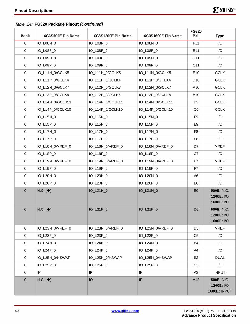
Pinout DescriptionsR
0 IO_L08N_0 IO_L08N_0 IO_L08N_0 F11 I/O
0 IO_L08P_0 IO_L08P_0 IO_L08P_0 E11 I/O
0 IO_L09N_0 IO_L09N_0 IO_L09N_0 D11 I/O
0 IO_L09P_0 IO_L09P_0 IO_L09P_0 C11 I/O
0 IO_L11N_0/GCLK5 IO_L11N_0/GCLK5 IO_L11N_0/GCLK5 E10 GCLK
0 IO_L11P_0/GCLK4 IO_L11P_0/GCLK4 IO_L11P_0/GCLK4 D10 GCLK
0 IO_L12N_0/GCLK7 IO_L12N_0/GCLK7 IO_L12N_0/GCLK7 A10 GCLK
0 IO_L12P_0/GCLK6 IO_L12P_0/GCLK6 IO_L12P_0/GCLK6 B10 GCLK
0 IO_L14N_0/GCLK11 IO_L14N_0/GCLK11 IO_L14N_0/GCLK11 D9 GCLK
0 IO_L14P_0/GCLK10 IO_L14P_0/GCLK10 IO_L14P_0/GCLK10 C9 GCLK
0 IO_L15N_0 IO_L15N_0 IO_L15N_0 F9 I/O
0 IO_L15P_0 IO_L15P_0 IO_L15P_0 E9 I/O
0 IO_L17N_0 IO_L17N_0 IO_L17N_0 F8 I/O
0 IO_L17P_0 IO_L17P_0 IO_L17P_0 E8 I/O
0 IO_L18N_0/VREF_0 IO_L18N_0/VREF_0 IO_L18N_0/VREF_0 D7 VREF
0 IO_L18P_0 IO_L18P_0 IO_L18P_0 C7 I/O
0 IO_L19N_0/VREF_0 IO_L19N_0/VREF_0 IO_L19N_0/VREF_0 E7 VREF
0 IO_L19P_0 IO_L19P_0 IO_L19P_0 F7 I/O
0 IO_L20N_0 IO_L20N_0 IO_L20N_0 A6 I/O
0 IO_L20P_0 IO_L20P_0 IO_L20P_0 B6 I/O
0 N.C. ( ) IO_L21N_0 IO_L21N_0 E6 500E: N.C.
1200E: I/O
1600E: I/O
0 N.C. ( ) IO_L21P_0 IO_L21P_0 D6 500E: N.C.
1200E: I/O
1600E: I/O
0 IO_L23N_0/VREF_0 IO_L23N_0/VREF_0 IO_L23N_0/VREF_0 D5 VREF
0 IO_L23P_0 IO_L23P_0 IO_L23P_0 C5 I/O
0 IO_L24N_0 IO_L24N_0 IO_L24N_0 B4 I/O
0 IO_L24P_0 IO_L24P_0 IO_L24P_0 A4 I/O
0 IO_L25N_0/HSWAP IO_L25N_0/HSWAP IO_L25N_0/HSWAP B3 DUAL
0 IO_L25P_0 IO_L25P_0 IO_L25P_0 C3 I/O
0 IP IP IP A3 INPUT
0 N.C. ( ) IO IP A12 500E: N.C.
1200E: I/O
1600E: INPUT
Table 24: FG320 Package Pinout (Continued)
Bank XC3S500E Pin Name XC3S1200E Pin Name XC3S1600E Pin NameFG320
Ball Type
40 www.xilinx.com DS312-4 (v1.1) March 21, 2005Advance Product Specification

Pinout DescriptionsR
0 IP IP IP C15 INPUT
0 IP_L02N_0 IP_L02N_0 IP_L02N_0 A15 INPUT
0 IP_L02P_0 IP_L02P_0 IP_L02P_0 B15 INPUT
0 IP_L07N_0 IP_L07N_0 IP_L07N_0 D12 INPUT
0 IP_L07P_0 IP_L07P_0 IP_L07P_0 C12 INPUT
0 IP_L10N_0 IP_L10N_0 IP_L10N_0 G10 INPUT
0 IP_L10P_0 IP_L10P_0 IP_L10P_0 F10 INPUT
0 IP_L13N_0/GCLK9 IP_L13N_0/GCLK9 IP_L13N_0/GCLK9 B9 GCLK
0 IP_L13P_0/GCLK8 IP_L13P_0/GCLK8 IP_L13P_0/GCLK8 B8 GCLK
0 IP_L16N_0 IP_L16N_0 IP_L16N_0 D8 INPUT
0 IP_L16P_0 IP_L16P_0 IP_L16P_0 C8 INPUT
0 IP_L22N_0 IP_L22N_0 IP_L22N_0 B5 INPUT
0 IP_L22P_0 IP_L22P_0 IP_L22P_0 A5 INPUT
0 VCCO_0 VCCO_0 VCCO_0 A9 VCCO
0 VCCO_0 VCCO_0 VCCO_0 C6 VCCO
0 VCCO_0 VCCO_0 VCCO_0 C13 VCCO
0 VCCO_0 VCCO_0 VCCO_0 G8 VCCO
0 VCCO_0 VCCO_0 VCCO_0 G11 VCCO
1 N.C. ( ) IO IO P16 500E: N.C.
1200E: I/O
1600E: I/O
1 IO_L01N_1/A15 IO_L01N_1/A15 IO_L01N_1/A15 T17 DUAL
1 IO_L01P_1/A16 IO_L01P_1/A16 IO_L01P_1/A16 U18 DUAL
1 IO_L02N_1/A13 IO_L02N_1/A13 IO_L02N_1/A13 T18 DUAL
1 IO_L02P_1/A14 IO_L02P_1/A14 IO_L02P_1/A14 R18 DUAL
1 IO_L03N_1/VREF_1 IO_L03N_1/VREF_1 IO_L03N_1/VREF_1 R16 VREF
1 IO_L03P_1 IO_L03P_1 IO_L03P_1 R15 I/O
1 N.C. ( ) IO_L04N_1 IO_L04N_1 N14 500E: N.C.
1200E: I/O
1600E: INPUT
1 N.C. ( ) IO_L04P_1 IO_L04P_1 N15 500E: N.C.
1200E: I/O
1600E: INPUT
1 IO_L05N_1/VREF_1 IO_L05N_1/VREF_1 IO_L05N_1/VREF_1 M13 VREF
1 IO_L05P_1 IO_L05P_1 IO_L05P_1 M14 I/O
1 IO_L06N_1 IO_L06N_1 IO_L06N_1 P18 I/O
Table 24: FG320 Package Pinout (Continued)
Bank XC3S500E Pin Name XC3S1200E Pin Name XC3S1600E Pin NameFG320
Ball Type
DS312-4 (v1.1) March 21, 2005 www.xilinx.com 41Advance Product Specification

Pinout DescriptionsR
1 IO_L06P_1 IO_L06P_1 IO_L06P_1 P17 I/O
1 IO_L07N_1 IO_L07N_1 IO_L07N_1 M16 I/O
1 IO_L07P_1 IO_L07P_1 IO_L07P_1 M15 I/O
1 IO_L08N_1 IO_L08N_1 IO_L08N_1 M18 I/O
1 IO_L08P_1 IO_L08P_1 IO_L08P_1 N18 I/O
1 IO_L09N_1/A11 IO_L09N_1/A11 IO_L09N_1/A11 L15 DUAL
1 IO_L09P_1/A12 IO_L09P_1/A12 IO_L09P_1/A12 L16 DUAL
1 IO_L10N_1/VREF_1 IO_L10N_1/VREF_1 IO_L10N_1/VREF_1 L17 VREF
1 IO_L10P_1 IO_L10P_1 IO_L10P_1 L18 I/O
1 IO_L11N_1/A9/RHCLK1 IO_L11N_1/A9/RHCLK1 IO_L11N_1/A9/RHCLK1 K12 RHCLK/DUAL
1 IO_L11P_1/A10/RHCLK0 IO_L11P_1/A10/RHCLK0 IO_L11P_1/A10/RHCLK0 K13 RHCLK/DUAL
1 IO_L12N_1/A7/RHCLK3/TRDY1
IO_L12N_1/A7/RHCLK3/TRDY1
IO_L12N_1/A7/RHCLK3/TRDY1
K14 RHCLK/DUAL
1 IO_L12P_1/A8/RHCLK2 IO_L12P_1/A8/RHCLK2 IO_L12P_1/A8/RHCLK2 K15 RHCLK/DUAL
1 IO_L13N_1/A5/RHCLK5 IO_L13N_1/A5/RHCLK5 IO_L13N_1/A5/RHCLK5 J16 RHCLK/DUAL
1 IO_L13P_1/A6/RHCLK4/IRDY1
IO_L13P_1/A6/RHCLK4/IRDY1
IO_L13P_1/A6/RHCLK4/IRDY1
J17 RHCLK/DUAL
1 IO_L14N_1/A3/RHCLK7 IO_L14N_1/A3/RHCLK7 IO_L14N_1/A3/RHCLK7 J14 RHCLK/DUAL
1 IO_L14P_1/A4/RHCLK6 IO_L14P_1/A4/RHCLK6 IO_L14P_1/A4/RHCLK6 J15 RHCLK/DUAL
1 IO_L15N_1/A1 IO_L15N_1/A1 IO_L15N_1/A1 J13 DUAL
1 IO_L15P_1/A2 IO_L15P_1/A2 IO_L15P_1/A2 J12 DUAL
1 IO_L16N_1/A0 IO_L16N_1/A0 IO_L16N_1/A0 H17 DUAL
1 IO_L16P_1 IO_L16P_1 IO_L16P_1 H16 I/O
1 IO_L17N_1 IO_L17N_1 IO_L17N_1 H15 I/O
1 IO_L17P_1 IO_L17P_1 IO_L17P_1 H14 I/O
1 IO_L18N_1 IO_L18N_1 IO_L18N_1 G16 I/O
1 IO_L18P_1 IO_L18P_1 IO_L18P_1 G15 I/O
1 IO_L19N_1 IO_L19N_1 IO_L19N_1 F17 I/O
1 IO_L19P_1 IO_L19P_1 IO_L19P_1 F18 I/O
1 IO_L20N_1 IO_L20N_1 IO_L20N_1 G13 I/O
1 IO_L20P_1 IO_L20P_1 IO_L20P_1 G14 I/O
1 IO_L21N_1 IO_L21N_1 IO_L21N_1 F14 I/O
1 IO_L21P_1 IO_L21P_1 IO_L21P_1 F15 I/O
1 N.C. ( ) IO_L22N_1 IO_L22N_1 E16 500E: N.C.
1200E: I/O
1600E: I/O
Table 24: FG320 Package Pinout (Continued)
Bank XC3S500E Pin Name XC3S1200E Pin Name XC3S1600E Pin NameFG320
Ball Type
42 www.xilinx.com DS312-4 (v1.1) March 21, 2005Advance Product Specification

Pinout DescriptionsR
1 N.C. ( ) IO_L22P_1 IO_L22P_1 E15 500E: N.C.
1200E: I/O
1600E: I/O
1 IO_L23N_1/LDC0 IO_L23N_1/LDC0 IO_L23N_1/LDC0 D16 DUAL
1 IO_L23P_1/HDC IO_L23P_1/HDC IO_L23P_1/HDC D17 DUAL
1 IO_L24N_1/LDC2 IO_L24N_1/LDC2 IO_L24N_1/LDC2 C17 DUAL
1 IO_L24P_1/LDC1 IO_L24P_1/LDC1 IO_L24P_1/LDC1 C18 DUAL
1 IP IP IP B18 INPUT
1 IO IP IP E17 500E: I/O
1200E: INPUT
1600E: INPUT
1 IP IP IP E18 INPUT
1 IP IP IP G18 INPUT
1 IP IP IP H13 INPUT
1 IP IP IP K17 INPUT
1 IP IP IP K18 INPUT
1 IP IP IP L13 INPUT
1 IP IP IP L14 INPUT
1 IP IP IP N17 INPUT
1 IO IP IP P15 500E: I/O
1200E: INPUT
1600E: INPUT
1 IP IP IP R17 INPUT
1 IP/VREF_1 IP/VREF_1 IP/VREF_1 D18 VREF
1 IP/VREF_1 IP/VREF_1 IP/VREF_1 H18 VREF
1 VCCO_1 VCCO_1 VCCO_1 F16 VCCO
1 VCCO_1 VCCO_1 VCCO_1 H12 VCCO
1 VCCO_1 VCCO_1 VCCO_1 J18 VCCO
1 VCCO_1 VCCO_1 VCCO_1 L12 VCCO
1 VCCO_1 VCCO_1 VCCO_1 N16 VCCO
2 IO IO IO P9 I/O
2 IO IO IO R11 I/O
2 IP IO IO U6 500E: INPUT
1200E: I/O
1600E: I/O
Table 24: FG320 Package Pinout (Continued)
Bank XC3S500E Pin Name XC3S1200E Pin Name XC3S1600E Pin NameFG320
Ball Type
DS312-4 (v1.1) March 21, 2005 www.xilinx.com 43Advance Product Specification

Pinout DescriptionsR
2 IP IO IO U13 500E: INPUT
1200E: I/O
1600E: I/O
2 N.C. ( ) IO IO V7 500E: N.C.
1200E: I/O
1600E: I/O
2 IO/D5 IO/D5 IO/D5 R9 DUAL
2 IO/M1 IO/M1 IO/M1 V11 DUAL
2 IO/VREF_2 IO/VREF_2 IO/VREF_2 T15 VREF
2 IO/VREF_2 IO/VREF_2 IO/VREF_2 U5 VREF
2 IO_L01N_2/INIT_B IO_L01N_2/INIT_B IO_L01N_2/INIT_B T3 DUAL
2 IO_L01P_2/CSO_B IO_L01P_2/CSO_B IO_L01P_2/CSO_B U3 DUAL
2 IO_L03N_2/MOSI/CSI_B IO_L03N_2/MOSI/CSI_B IO_L03N_2/MOSI/CSI_B T4 DUAL
2 IO_L03P_2/DOUT/BUSY IO_L03P_2/DOUT/BUSY IO_L03P_2/DOUT/BUSY U4 DUAL
2 IO_L04N_2 IO_L04N_2 IO_L04N_2 T5 I/O
2 IO_L04P_2 IO_L04P_2 IO_L04P_2 R5 I/O
2 IO_L05N_2 IO_L05N_2 IO_L05N_2 P6 I/O
2 IO_L05P_2 IO_L05P_2 IO_L05P_2 R6 I/O
2 N.C. ( ) IO_L06N_2/VREF_2 IO_L06N_2/VREF_2 V6 500E: N.C.
1200E: VREF
1600E: VREF
2 N.C. ( ) IO_L06P_2 IO_L06P_2 V5 500E: N.C.
1200E: I/O
1600E: I/O
2 IO_L07N_2 IO_L07N_2 IO_L07N_2 P7 I/O
2 IO_L07P_2 IO_L07P_2 IO_L07P_2 N7 I/O
2 IO_L09N_2 IO_L09N_2 IO_L09N_2 N8 I/O
2 IO_L09P_2 IO_L09P_2 IO_L09P_2 P8 I/O
2 IO_L10N_2 IO_L10N_2 IO_L10N_2 T8 I/O
2 IO_L10P_2 IO_L10P_2 IO_L10P_2 R8 I/O
2 IO_L12N_2/D6/GCLK13 IO_L12N_2/D6/GCLK13 IO_L12N_2/D6/GCLK13 M9 DUAL/GCLK
2 IO_L12P_2/D7/GCLK12 IO_L12P_2/D7/GCLK12 IO_L12P_2/D7/GCLK12 N9 DUAL/GCLK
2 IO_L13N_2/D3/GCLK15 IO_L13N_2/D3/GCLK15 IO_L13N_2/D3/GCLK15 V9 DUAL/GCLK
2 IO_L13P_2/D4/GCLK14 IO_L13P_2/D4/GCLK14 IO_L13P_2/D4/GCLK14 U9 DUAL/GCLK
2 IO_L15N_2/D1/GCLK3 IO_L15N_2/D1/GCLK3 IO_L15N_2/D1/GCLK3 P10 DUAL/GCLK
2 IO_L15P_2/D2/GCLK2 IO_L15P_2/D2/GCLK2 IO_L15P_2/D2/GCLK2 R10 DUAL/GCLK
2 IO_L16N_2/DIN/D0 IO_L16N_2/DIN/D0 IO_L16N_2/DIN/D0 N10 DUAL
Table 24: FG320 Package Pinout (Continued)
Bank XC3S500E Pin Name XC3S1200E Pin Name XC3S1600E Pin NameFG320
Ball Type
44 www.xilinx.com DS312-4 (v1.1) March 21, 2005Advance Product Specification

Pinout DescriptionsR
2 IO_L16P_2/M0 IO_L16P_2/M0 IO_L16P_2/M0 M10 DUAL
2 IO_L18N_2 IO_L18N_2 IO_L18N_2 N11 I/O
2 IO_L18P_2 IO_L18P_2 IO_L18P_2 P11 I/O
2 IO_L19N_2/VREF_2 IO_L19N_2/VREF_2 IO_L19N_2/VREF_2 V13 VREF
2 IO_L19P_2 IO_L19P_2 IO_L19P_2 V12 I/O
2 IO_L20N_2 IO_L20N_2 IO_L20N_2 R12 I/O
2 IO_L20P_2 IO_L20P_2 IO_L20P_2 T12 I/O
2 N.C. ( ) IO_L21N_2 IO_L21N_2 P12 500E: N.C.
1200E: I/O
1600E: I/O
2 N.C. ( ) IO_L21P_2 IO_L21P_2 N12 500E: N.C.
1200E: I/O
1600E: I/O
2 IO_L22N_2/A22 IO_L22N_2/A22 IO_L22N_2/A22 R13 DUAL
2 IO_L22P_2/A23 IO_L22P_2/A23 IO_L22P_2/A23 P13 DUAL
2 IO_L24N_2/A20 IO_L24N_2/A20 IO_L24N_2/A20 R14 DUAL
2 IO_L24P_2/A21 IO_L24P_2/A21 IO_L24P_2/A21 T14 DUAL
2 IO_L25N_2/VS1/A18 IO_L25N_2/VS1/A18 IO_L25N_2/VS1/A18 U15 DUAL
2 IO_L25P_2/VS2/A19 IO_L25P_2/VS2/A19 IO_L25P_2/VS2/A19 V15 DUAL
2 IO_L26N_2/CCLK IO_L26N_2/CCLK IO_L26N_2/CCLK U16 DUAL
2 IO_L26P_2/VS0/A17 IO_L26P_2/VS0/A17 IO_L26P_2/VS0/A17 T16 DUAL
2 IP IP IP V2 INPUT
2 IP IP IP V16 INPUT
2 IP_L02N_2 IP_L02N_2 IP_L02N_2 V3 INPUT
2 IP_L02P_2 IP_L02P_2 IP_L02P_2 V4 INPUT
2 IP_L08N_2 IP_L08N_2 IP_L08N_2 R7 INPUT
2 IP_L08P_2 IP_L08P_2 IP_L08P_2 T7 INPUT
2 IP_L11N_2/VREF_2 IP_L11N_2/VREF_2 IP_L11N_2/VREF_2 V8 VREF
2 IP_L11P_2 IP_L11P_2 IP_L11P_2 U8 INPUT
2 IP_L14N_2/M2/GCLK1 IP_L14N_2/M2/GCLK1 IP_L14N_2/M2/GCLK1 T10 DUAL/GCLK
2 IP_L14P_2/RDWR_B/GCLK0
IP_L14P_2/RDWR_B/GCLK0
IP_L14P_2/RDWR_B/GCLK0
U10 DUAL/GCLK
2 IP_L17N_2 IP_L17N_2 IP_L17N_2 U11 INPUT
2 IP_L17P_2 IP_L17P_2 IP_L17P_2 T11 INPUT
2 IP_L23N_2 IP_L23N_2 IP_L23N_2 U14 INPUT
2 IP_L23P_2 IP_L23P_2 IP_L23P_2 V14 INPUT
Table 24: FG320 Package Pinout (Continued)
Bank XC3S500E Pin Name XC3S1200E Pin Name XC3S1600E Pin NameFG320
Ball Type
DS312-4 (v1.1) March 21, 2005 www.xilinx.com 45Advance Product Specification

Pinout DescriptionsR
2 VCCO_2 VCCO_2 VCCO_2 M8 VCCO
2 VCCO_2 VCCO_2 VCCO_2 M11 VCCO
2 VCCO_2 VCCO_2 VCCO_2 T6 VCCO
2 VCCO_2 VCCO_2 VCCO_2 T13 VCCO
2 VCCO_2 VCCO_2 VCCO_2 V10 VCCO
3 N.C. ( ) IO IO D4 500E: N.C.
1200E: I/O
1600E: I/O
3 IO_L01N_3 IO_L01N_3 IO_L01N_3 C2 I/O
3 IO_L01P_3 IO_L01P_3 IO_L01P_3 C1 I/O
3 IO_L02N_3/VREF_3 IO_L02N_3/VREF_3 IO_L02N_3/VREF_3 D2 VREF
3 IO_L02P_3 IO_L02P_3 IO_L02P_3 D1 I/O
3 IO_L03N_3 IO_L03N_3 IO_L03N_3 E1 I/O
3 IO_L03P_3 IO_L03P_3 IO_L03P_3 E2 I/O
3 N.C. ( ) IO_L04N_3 IO_L04N_3 E3 500E: N.C.
1200E: I/O
1600E: I/O
3 N.C. ( ) IO_L04P_3 IO_L04P_3 E4 500E: N.C.
1200E: I/O
1600E: I/O
3 IO_L05N_3 IO_L05N_3 IO_L05N_3 F2 I/O
3 IO_L05P_3 IO_L05P_3 IO_L05P_3 F1 I/O
3 IO_L06N_3/VREF_3 IO_L06N_3/VREF_3 IO_L06N_3/VREF_3 G4 VREF
3 IO_L06P_3 IO_L06P_3 IO_L06P_3 G3 I/O
3 IO_L07N_3 IO_L07N_3 IO_L07N_3 G5 I/O
3 IO_L07P_3 IO_L07P_3 IO_L07P_3 G6 I/O
3 IO_L08N_3 IO_L08N_3 IO_L08N_3 H5 I/O
3 IO_L08P_3 IO_L08P_3 IO_L08P_3 H6 I/O
3 IO_L09N_3 IO_L09N_3 IO_L09N_3 H3 I/O
3 IO_L09P_3 IO_L09P_3 IO_L09P_3 H4 I/O
3 IO_L10N_3 IO_L10N_3 IO_L10N_3 H1 I/O
3 IO_L10P_3 IO_L10P_3 IO_L10P_3 H2 I/O
3 IO_L11N_3/LHCLK1 IO_L11N_3/LHCLK1 IO_L11N_3/LHCLK1 J4 LHCLK
3 IO_L11P_3/LHCLK0 IO_L11P_3/LHCLK0 IO_L11P_3/LHCLK0 J5 LHCLK
3 IO_L12N_3/LHCLK3/IRDY2
IO_L12N_3/LHCLK3/IRDY2
IO_L12N_3/LHCLK3/IRDY2
J2 LHCLK
3 IO_L12P_3/LHCLK2 IO_L12P_3/LHCLK2 IO_L12P_3/LHCLK2 J1 LHCLK
Table 24: FG320 Package Pinout (Continued)
Bank XC3S500E Pin Name XC3S1200E Pin Name XC3S1600E Pin NameFG320
Ball Type
46 www.xilinx.com DS312-4 (v1.1) March 21, 2005Advance Product Specification

Pinout DescriptionsR
3 IO_L13N_3/LHCLK5 IO_L13N_3/LHCLK5 IO_L13N_3/LHCLK5 K4 LHCLK
3 IO_L13P_3/LHCLK4/TRDY2
IO_L13P_3/LHCLK4/TRDY2
IO_L13P_3/LHCLK4/TRDY2
K3 LHCLK
3 IO_L14N_3/LHCLK7 IO_L14N_3/LHCLK7 IO_L14N_3/LHCLK7 K5 LHCLK
3 IO_L14P_3/LHCLK6 IO_L14P_3/LHCLK6 IO_L14P_3/LHCLK6 K6 LHCLK
3 IO_L15N_3 IO_L15N_3 IO_L15N_3 L2 I/O
3 IO_L15P_3 IO_L15P_3 IO_L15P_3 L1 I/O
3 IO_L16N_3 IO_L16N_3 IO_L16N_3 L4 I/O
3 IO_L16P_3 IO_L16P_3 IO_L16P_3 L3 I/O
3 IO_L17N_3/VREF_3 IO_L17N_3/VREF_3 IO_L17N_3/VREF_3 L5 VREF
3 IO_L17P_3 IO_L17P_3 IO_L17P_3 L6 I/O
3 IO_L18N_3 IO_L18N_3 IO_L18N_3 M3 I/O
3 IO_L18P_3 IO_L18P_3 IO_L18P_3 M4 I/O
3 IO_L19N_3 IO_L19N_3 IO_L19N_3 M6 I/O
3 IO_L19P_3 IO_L19P_3 IO_L19P_3 M5 I/O
3 IO_L20N_3 IO_L20N_3 IO_L20N_3 N5 I/O
3 IO_L20P_3 IO_L20P_3 IO_L20P_3 N4 I/O
3 IO_L21N_3 IO_L21N_3 IO_L21N_3 P1 I/O
3 IO_L21P_3 IO_L21P_3 IO_L21P_3 P2 I/O
3 N.C. ( ) IO_L22N_3 IO_L22N_3 P4 500E: N.C.
1200E: I/O
1600E: I/O
3 N.C. ( ) IO_L22P_3 IO_L22P_3 P3 500E: N.C.
1200E: I/O
1600E: I/O
3 IO_L23N_3 IO_L23N_3 IO_L23N_3 R2 I/O
3 IO_L23P_3 IO_L23P_3 IO_L23P_3 R3 I/O
3 IO_L24N_3 IO_L24N_3 IO_L24N_3 T1 I/O
3 IO_L24P_3 IO_L24P_3 IO_L24P_3 T2 I/O
3 IP IP IP D3 INPUT
3 IO IP IP F4 500E: I/O
1200E: INPUT
1600E: INPUT
3 IP IP IP F5 INPUT
3 IP IP IP G1 INPUT
3 IP IP IP J7 INPUT
3 IP IP IP K2 INPUT
Table 24: FG320 Package Pinout (Continued)
Bank XC3S500E Pin Name XC3S1200E Pin Name XC3S1600E Pin NameFG320
Ball Type
DS312-4 (v1.1) March 21, 2005 www.xilinx.com 47Advance Product Specification
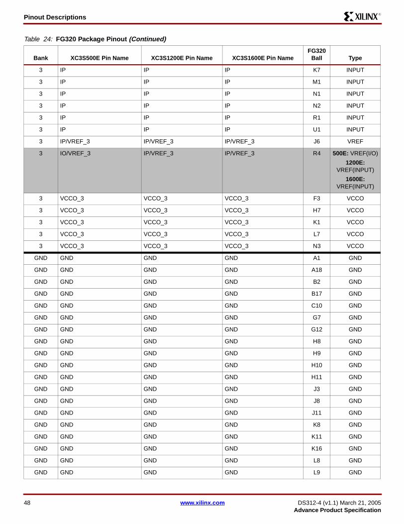
Pinout DescriptionsR
3 IP IP IP K7 INPUT
3 IP IP IP M1 INPUT
3 IP IP IP N1 INPUT
3 IP IP IP N2 INPUT
3 IP IP IP R1 INPUT
3 IP IP IP U1 INPUT
3 IP/VREF_3 IP/VREF_3 IP/VREF_3 J6 VREF
3 IO/VREF_3 IP/VREF_3 IP/VREF_3 R4 500E: VREF(I/O)
1200E: VREF(INPUT)
1600E: VREF(INPUT)
3 VCCO_3 VCCO_3 VCCO_3 F3 VCCO
3 VCCO_3 VCCO_3 VCCO_3 H7 VCCO
3 VCCO_3 VCCO_3 VCCO_3 K1 VCCO
3 VCCO_3 VCCO_3 VCCO_3 L7 VCCO
3 VCCO_3 VCCO_3 VCCO_3 N3 VCCO
GND GND GND GND A1 GND
GND GND GND GND A18 GND
GND GND GND GND B2 GND
GND GND GND GND B17 GND
GND GND GND GND C10 GND
GND GND GND GND G7 GND
GND GND GND GND G12 GND
GND GND GND GND H8 GND
GND GND GND GND H9 GND
GND GND GND GND H10 GND
GND GND GND GND H11 GND
GND GND GND GND J3 GND
GND GND GND GND J8 GND
GND GND GND GND J11 GND
GND GND GND GND K8 GND
GND GND GND GND K11 GND
GND GND GND GND K16 GND
GND GND GND GND L8 GND
GND GND GND GND L9 GND
Table 24: FG320 Package Pinout (Continued)
Bank XC3S500E Pin Name XC3S1200E Pin Name XC3S1600E Pin NameFG320
Ball Type
48 www.xilinx.com DS312-4 (v1.1) March 21, 2005Advance Product Specification

Pinout DescriptionsR
GND GND GND GND L10 GND
GND GND GND GND L11 GND
GND GND GND GND M7 GND
GND GND GND GND M12 GND
GND GND GND GND T9 GND
GND GND GND GND U2 GND
GND GND GND GND U17 GND
GND GND GND GND V1 GND
GND GND GND GND V18 GND
VCCAUX DONE DONE DONE V17 CONFIG
VCCAUX PROG_B PROG_B PROG_B B1 CONFIG
VCCAUX TCK TCK TCK A17 JTAG
VCCAUX TDI TDI TDI A2 JTAG
VCCAUX TDO TDO TDO C16 JTAG
VCCAUX TMS TMS TMS D15 JTAG
VCCAUX VCCAUX VCCAUX VCCAUX B7 VCCAUX
VCCAUX VCCAUX VCCAUX VCCAUX B12 VCCAUX
VCCAUX VCCAUX VCCAUX VCCAUX G2 VCCAUX
VCCAUX VCCAUX VCCAUX VCCAUX G17 VCCAUX
VCCAUX VCCAUX VCCAUX VCCAUX M2 VCCAUX
VCCAUX VCCAUX VCCAUX VCCAUX M17 VCCAUX
VCCAUX VCCAUX VCCAUX VCCAUX U7 VCCAUX
VCCAUX VCCAUX VCCAUX VCCAUX U12 VCCAUX
VCCINT VCCINT VCCINT VCCINT E5 VCCINT
VCCINT VCCINT VCCINT VCCINT E14 VCCINT
VCCINT VCCINT VCCINT VCCINT F6 VCCINT
VCCINT VCCINT VCCINT VCCINT F13 VCCINT
VCCINT VCCINT VCCINT VCCINT N6 VCCINT
VCCINT VCCINT VCCINT VCCINT N13 VCCINT
VCCINT VCCINT VCCINT VCCINT P5 VCCINT
VCCINT VCCINT VCCINT VCCINT P14 VCCINT
Table 24: FG320 Package Pinout (Continued)
Bank XC3S500E Pin Name XC3S1200E Pin Name XC3S1600E Pin NameFG320
Ball Type
DS312-4 (v1.1) March 21, 2005 www.xilinx.com 49Advance Product Specification

Pinout DescriptionsR
User I/Os by Bank Table 25, Table 26, and Table 27 indicate how the availableuser-I/O pins are distributed between the four I/O banks onthe FG320 package.
Footprint Migration DifferencesTable 28 summarizes any footprint and functionality differ-ences between the XC3S500E, the XC3S1200E, and theXC3S1600E FPGAs that may affect easy migrationbetween devices available in the FG320 package. There are26 such balls. All other pins not listed in Table 28 uncondi-tionally migrate between Spartan-3E devices available inthe FG320 package.
The XC3S500E is duplicated on both the left and right sidesof the table to show migrations to and from the XC3S1200Eand the XC3S1600E. The arrows indicate the direction foreasy migration. A double-ended arrow ( ) indicates thatthe two pins have identical functionality. A left-facing arrow( ) indicates that the pin on the device on the right uncon-ditionally migrates to the pin on the device on the left. It maybe possible to migrate the opposite direction depending onthe I/O configuration. For example, an I/O pin (Type = I/O)
Table 25: User I/Os Per Bank for XC3S500E in the FG320 Package
Package Edge I/O Bank
Maximum I/O
All Possible I/O Pins by Type
I/O INPUT DUAL VREF GCLK
Top 0 58 29 14 1 6 8
Right 1 58 22 10 21 5 0
Bottom 2 58 17 13 24 4 0
Left 3 58 34 11 0 5 8
TOTAL 232 102 48 46 20 16
Table 26: User I/Os Per Bank for XC3S1200E in the FG320 Package
Package Edge I/O Bank
Maximum I/O
All Possible I/O Pins by Type
I/O INPUT DUAL VREF GCLK
Top 0 61 34 12 1 6 8
Right 1 63 25 12 21 5 0
Bottom 2 63 23 11 24 5 0
Left 3 63 38 12 0 5 8
TOTAL 250 120 47 46 21 16
Table 27: User I/Os Per Bank for XC3S1600E in the FG320 Package
Package Edge I/O Bank
Maximum I/O
All Possible I/O Pins by Type
I/O INPUT DUAL VREF GCLK
Top 0 61 33 13 1 6 8
Right 1 63 25 12 21 5 0
Bottom 2 63 23 11 24 5 0
Left 3 63 38 12 0 5 8
TOTAL 250 119 48 46 21 16
50 www.xilinx.com DS312-4 (v1.1) March 21, 2005Advance Product Specification

Pinout DescriptionsR
can migrate to an input-only pin (Type = INPUT) if the I/Opin is configured as an input.
Table 28: FG320 Footprint Migration Differences
Pin Bank XC3S500E Migration XC3S1200E Migration XC3S1600E Migration XC3S500E
A7 0 INPUT I/O I/O INPUT
A12 0 N.C. I/O INPUT N.C.
D4 3 N.C. I/O I/O N.C.
D6 0 N.C. I/O I/O N.C.
D13 0 INPUT I/O I/O INPUT
E3 3 N.C. I/O I/O N.C.
E4 3 N.C. I/O I/O N.C.
E6 0 N.C. I/O I/O N.C.
E15 1 N.C. I/O I/O N.C.
E16 1 N.C. I/O I/O N.C.
E17 1 I/O INPUT INPUT I/O
F4 3 I/O INPUT INPUT I/O
N12 2 N.C. I/O I/O N.C.
N14 1 N.C. I/O I/O N.C.
N15 1 N.C. I/O I/O N.C.
P3 3 N.C. I/O I/O N.C.
P4 3 N.C. I/O I/O N.C.
P12 2 N.C. I/O I/O N.C.
P15 1 I/O INPUT INPUT I/O
P16 1 N.C. I/O I/O N.C.
R4 3 VREF(I/O) VREF(INPUT) VREF(INPUT) VREF(I/O)
U6 2 INPUT I/O I/O INPUT
U13 2 INPUT I/O I/O INPUT
V5 2 N.C. I/O I/O N.C.
V6 2 N.C. VREF VREF N.C.
V7 2 N.C. I/O I/O N.C.
DIFFERENCES 26 1 26
Legend:
This pin is identical on both the device on the left and the right.
This pin can unconditionally migrate from the device on the left to the device on the right. Migration in the other direction may be possible depending on how the pin is configured for the device on the right.
This pin can unconditionally migrate from the device on the right to the device on the left. Migration in the other direction may be possible depending on how the pin is configured for the device on the left.
DS312-4 (v1.1) March 21, 2005 www.xilinx.com 51Advance Product Specification

Pinout DescriptionsR
FG320 Footprint
Figure 8: FG320 Package Footprint (top view)
1 2 3 4 5 6 7 8 9 10 11 12 13 14 15 16 17 18
A GND TDI INPUT I/OL24P_0
INPUTL22P_0
I/OL20N_0
INPUTI/O VCCO_0
I/OL12N_0GCLK7
I/OINPUT
I/OL05P_0
I/OL04N_0
INPUTL02N_0
I/OL01N_0
TCK GND
B PROG_B GNDI/O
L25N_0HSWAP
I/OL24N_0
INPUTL22N_0
I/OL20P_0
VCCAUXINPUTL13P_0GCLK8
INPUTL13N_0GCLK9
I/OL12P_0GCLK6
I/OVREF_0
VCCAUXI/O
L05N_0VREF_0
I/OL04P_0
INPUTL02P_0
I/OL01P_0
GND INPUT
C I/OL01P_3
I/OL01N_3
I/OL25P_0
I/O I/OL23P_0
VCCO_0 I/OL18P_0
INPUTL16P_0
I/OL14P_0GCLK10
GND I/OL09P_0
INPUTL07P_0
VCCO_0I/O
L03N_0VREF_0
INPUT TDOI/O
L24N_1LDC2
I/OL24P_1LDC1
D I/OL02P_3
I/OL02N_3VREF_3
INPUTI/O I/O
L23N_0VREF_0
I/OL21P_0
I/OL18N_0VREF_0
INPUTL16N_0
I/OL14N_0GCLK11
I/OL11P_0GCLK4
I/OL09N_0
INPUTL07N_0
INPUT I/OL03P_0
TMSI/O
L23N_1LDC0
I/OL23P_1
HDC
INPUTVREF_1
E I/OL03N_3
I/OL03P_3
I/OL04N_3
I/OL04P_3 VCCINT
I/OL21N_0
I/OL19N_0VREF_0
I/OL17P_0
I/OL15P_0
I/OL11N_0GCLK5
I/OL08P_0
I/OL06N_0
I/O VCCINTI/O
L22P_1I/O
L22N_1INPUT
INPUT
F I/OL05P_3
I/OL05N_3
VCCO_3INPUT
INPUT VCCINT I/OL19P_0
I/OL17N_0
I/OL15N_0
INPUTL10P_0
I/OL08N_0
I/OL06P_0
VCCINT I/OL21N_1
I/OL21P_1
VCCO_1 I/OL19N_1
I/OL19P_1
G INPUT VCCAUX I/OL06P_3
I/OL06N_3VREF_3
I/OL07N_3
I/OL07P_3
GND VCCO_0 I/O INPUTL10N_0
VCCO_0 GND I/OL20N_1
I/OL20P_1
I/OL18P_1
I/OL18N_1
VCCAUX INPUT
H I/OL10N_3
I/OL10P_3
I/OL09N_3
I/OL09P_3
I/OL08N_3
I/OL08P_3
VCCO_3 GND GND GND GND VCCO_1 INPUT I/OL17P_1
I/OL17N_1
I/OL16P_1
I/OL16N_1
A0
INPUTVREF_1
JI/O
L12P_3LHCLK2
I/OL12N_3LHCLK3IRDY2
GNDI/O
L11N_3LHCLK1
I/OL11P_3LHCLK0
INPUTVREF_3
INPUT GND GNDI/O
L15P_1A2
I/OL15N_1
A14
_1VCCO_1
K VCCO_3 INPUTI/O
L13P_3LHCLK4TRDY2
I/OL13N_3LHCLK5
I/OL14N_3LHCLK7
I/OL14P_3LHCLK6
INPUT GND GND GND INPUT INPUT
L I/OL15P_3
I/OL15N_3
I/OL16P_3
I/OL16N_3
I/OL17N_3VREF_3
I/OL17P_3
VCCO_3 GND GND GND GND VCCO_1 INPUT INPUTI/O
L09N_1A11
I/OL09P_1
A12
I/OL10N_1VREF_1
I/OL10P_1
M INPUT VCCAUX I/OL18N_3
I/OL18P_3
I/OL19P_3
I/OL19N_3
GND VCCO_2I/O
L16P_2M0
VCCO_2 GNDI/O
L05N_1VREF_1
I/OL05P_1
I/OL07P_1
I/OL07N_1
VCCAUX I/OL08N_1
N INPUT INPUT VCCO_3 I/OL20P_3
I/OL20N_3
VCCINT I/OL07P_2
I/OL09N_2
I/O I/OL16N_2
DIND0
I/OL18N_2
I/OL21P_2 VCCINT
I/OL04N_1
I/OL04P_1 VCCO_1 INPUT I/O
L08P_1
P I/OL21N_3
I/OL21P_3
I/OL22P_3
I/OL22N_3 VCCINT I/O
L05N_2I/O
L07N_2I/O
L09P_2I/O I/O
L18P_2
I/OL21N_2
I/OL22P_2
A23VCCINT
INPUT I/O I/OL06P_1
I/OL06N_1
R INPUT I/OL23N_3
I/OL23P_3
INPUTVREF_3 I/O
L04P_2I/O
L05P_2INPUTL08N_2
I/OL10P_2
I/OD5
I/O I/OL20N_2
I/OL22N_2
A22
I/OL24N_2
A20
I/OL03P_1
I/OL03N_1VREF_1
INPUTI/O
L02P_1A14
T I/OL24N_3
I/OL24P_3
I/OL01N_2INIT_B
I/OL03N_2MOSICSI_B
I/OL04N_2
VCCO_2 INPUTL08P_2
I/OL10N_2
GND INPUTL17P_2
I/OL20P_2
VCCO_2I/O
L24P_2A21
I/OVREF_2
I/OL26P_2
VS0A17
I/OL01N_1
A15
I/OL02N_1
A13
U INPUT GNDI/O
L01P_2CSO_B
I/OL03P_2DOUTBUSY
I/OVREF_2
INPUTVCCAUX INPUT
L11P_2INPUTL17N_2
VCCAUXINPUT INPUT
L23N_2
I/OL25N_2
VS1A18
I/OL26N_2CCLK
GNDI/O
L01P_1A16
V GND INPUT INPUTL02N_2
INPUTL02P_2
I/OL06P_2
I/OL06N_2VREF_2
I/O INPUTL11N_2VREF_2
VCCO_2 I/OM1
I/OL19P_2
I/OL19N_2VREF_2
INPUTL23P_2
I/OL25P_2
VS2A19
INPUT DONE GND
Bank 0
Ban
k3
Ban
k1
Bank 2
I/OL14N_1
A3RHCLK7 RHCLK6
L14P_1A4
I/OL13N_1
A5RHCLK5
I/O I/OL13P
A6RHCLK4IRDY1
L11N_1A9
RHCLK1
I/O I/OL11P_1
RHCLK0A10
TRDY1RHCLK3
A7L12N_1
I/O I/OL12P_1
RHCLK2A8
I/OL12N_2
D6GCLK13
GCLK12D7
L12P_2
GCLK3D1
L15N_2I/O
GCLK2D2
L15P_2I/O
GCLK1M2
L14N_2INPUT
GCLK0
L14P_2RDWR_B
INPUT
GCLK14D4
L13P_2I/O
GCLK15D3
L13N_2I/O
DS312-4_06_021605
I/O: Unrestricted, general-purpose user I/O 46 DUAL: Configuration pin, then
possible user-I/OVREF: User I/O or input voltage reference for bank
INPUT: Unrestricted, general-purpose input pin 16 GCLK: User I/O, input, or
global buffer input 20 VCCO: Output voltage supply for bank
2 CONFIG: Dedicated configuration pins 4 JTAG: Dedicated JTAG port
pins 8 VCCINT: Internal core supply voltage (+1.2V)
0 N.C.: Not connected 28 GND: Ground 8 VCCAUX: Auxiliary supply voltage (+2.5V)
52 www.xilinx.com DS312-4 (v1.1) March 21, 2005Advance Product Specification

Pinout DescriptionsR
FG400: 400-ball Fine-pitch Ball Grid ArrayThe 400-ball fine-pitch ball grid array, FG400, supports twodifferent Spartan-3E FPGAs, including the XC3S1200E andthe XC3S1600E. Both devices share a common footprint forthis package as shown in Table 29 and Figure 9.
Table 29 lists all the FG400 package pins. They are sortedby bank number and then by pin name. Pairs of pins thatform a differential I/O pair appear together in the table. Thetable also shows the pin number for each pin and the pintype, as defined earlier.
An electronic version of this package pinout table and foot-print diagram is available for download from the Xilinx web-site at http://www.xilinx.com/bvdocs/publications/s3e_pin.zip.
Pinout Table
Table 29: FG400 Package Pinout
Bank
XC3S1200EXC3S1600EPin Name
FG400 Ball Type
0 IO A3 I/O
0 IO A8 I/O
0 IO A12 I/O
0 IO C7 I/O
0 IO C10 I/O
0 IO E8 I/O
0 IO E13 I/O
0 IO E16 I/O
0 IO F13 I/O
0 IO F14 I/O
0 IO G7 I/O
0 IO/VREF_0 C11 VREF
0 IO_L01N_0 B17 I/O
0 IO_L01P_0 C17 I/O
0 IO_L03N_0/VREF_0 A18 VREF
0 IO_L03P_0 A19 I/O
0 IO_L04N_0 A17 I/O
0 IO_L04P_0 A16 I/O
0 IO_L06N_0 A15 I/O
0 IO_L06P_0 B15 I/O
0 IO_L07N_0 C14 I/O
0 IO_L07P_0 D14 I/O
0 IO_L09N_0/VREF_0 A13 VREF
0 IO_L09P_0 A14 I/O
0 IO_L10N_0 B13 I/O
0 IO_L10P_0 C13 I/O
0 IO_L11N_0 C12 I/O
0 IO_L11P_0 D12 I/O
0 IO_L12N_0 E12 I/O
0 IO_L12P_0 F12 I/O
0 IO_L14N_0/GCLK5 G11 GCLK
0 IO_L14P_0/GCLK4 F11 GCLK
0 IO_L15N_0/GCLK7 E10 GCLK
0 IO_L15P_0/GCLK6 E11 GCLK
0 IO_L17N_0/GCLK11 A9 GCLK
0 IO_L17P_0/GCLK10 A10 GCLK
0 IO_L18N_0 F9 I/O
0 IO_L18P_0 E9 I/O
0 IO_L20N_0 C9 I/O
0 IO_L20P_0 D9 I/O
0 IO_L21N_0/VREF_0 B8 VREF
0 IO_L21P_0 B9 I/O
0 IO_L23N_0/VREF_0 F7 VREF
0 IO_L23P_0 F8 I/O
0 IO_L24N_0 A6 I/O
0 IO_L24P_0 A7 I/O
0 IO_L26N_0 B5 I/O
0 IO_L26P_0 B6 I/O
0 IO_L27N_0 D6 I/O
0 IO_L27P_0 C6 I/O
0 IO_L29N_0/VREF_0 C5 VREF
0 IO_L29P_0 D5 I/O
0 IO_L30N_0 A2 I/O
0 IO_L30P_0 B2 I/O
0 IO_L31N_0/HSWAP D4 DUAL
0 IO_L31P_0 C4 I/O
Table 29: FG400 Package Pinout
Bank
XC3S1200EXC3S1600EPin Name
FG400 Ball Type
DS312-4 (v1.1) March 21, 2005 www.xilinx.com 53Advance Product Specification

Pinout DescriptionsR
0 IP B18 INPUT
0 IP E5 INPUT
0 IP_L02N_0 C16 INPUT
0 IP_L02P_0 D16 INPUT
0 IP_L05N_0 D15 INPUT
0 IP_L05P_0 C15 INPUT
0 IP_L08N_0 E14 INPUT
0 IP_L08P_0 E15 INPUT
0 IP_L10N_0 G14 INPUT
0 IP_L10P_0 G13 INPUT
0 IP_L13N_0 B11 INPUT
0 IP_L13P_0 B12 INPUT
0 IP_L16N_0/GCLK9 G10 GCLK
0 IP_L16P_0/GCLK8 H10 GCLK
0 IP_L19N_0 G9 INPUT
0 IP_L19P_0 G8 INPUT
0 IP_L22N_0 C8 INPUT
0 IP_L22P_0 D8 INPUT
0 IP_L25N_0 E6 INPUT
0 IP_L25P_0 E7 INPUT
0 IP_L28N_0 A4 INPUT
0 IP_L28P_0 A5 INPUT
0 VCCO_0 B4 VCCO
0 VCCO_0 B10 VCCO
0 VCCO_0 B16 VCCO
0 VCCO_0 D7 VCCO
0 VCCO_0 D13 VCCO
0 VCCO_0 F10 VCCO
1 IO_L01N_1/A15 U18 DUAL
1 IO_L01P_1/A16 U17 DUAL
1 IO_L02N_1/A13 T18 DUAL
1 IO_L02P_1/A14 T17 DUAL
1 IO_L03N_1/VREF_1 V19 VREF
1 IO_L03P_1 U19 I/O
Table 29: FG400 Package Pinout
Bank
XC3S1200EXC3S1600EPin Name
FG400 Ball Type
1 IO_L04N_1 W20 I/O
1 IO_L04P_1 V20 I/O
1 IO_L05N_1 R18 I/O
1 IO_L05P_1 R17 I/O
1 IO_L06N_1 T20 I/O
1 IO_L06P_1 U20 I/O
1 IO_L07N_1 P18 I/O
1 IO_L07P_1 P17 I/O
1 IO_L08N_1/VREF_1 P20 VREF
1 IO_L08P_1 R20 I/O
1 IO_L09N_1 P16 I/O
1 IO_L09P_1 N16 I/O
1 IO_L10N_1 N19 I/O
1 IO_L10P_1 N18 I/O
1 IO_L11N_1 N15 I/O
1 IO_L11P_1 M15 I/O
1 IO_L12N_1/A11 M18 DUAL
1 IO_L12P_1/A12 M17 DUAL
1 IO_L13N_1/VREF_1 L19 VREF
1 IO_L13P_1 M19 I/O
1 IO_L14N_1/A9/RHCLK1 L16 RHCLK/DUAL
1 IO_L14P_1/A10/RHCLK0 M16 RHCLK/DUAL
1 IO_L15N_1/A7/RHCLK3/TRDY1
L14 RHCLK/DUAL
1 IO_L15P_1/A8/RHCLK2 L15 RHCLK/DUAL
1 IO_L16N_1/A5/RHCLK5 K14 RHCLK/DUAL
1 IO_L16P_1/A6/RHCLK4/IRDY1
K13 RHCLK/DUAL
1 IO_L17N_1/A3/RHCLK7 J20 RHCLK/DUAL
1 IO_L17P_1/A4/RHCLK6 K20 RHCLK/DUAL
1 IO_L18N_1/A1 K16 DUAL
1 IO_L18P_1/A2 J16 DUAL
Table 29: FG400 Package Pinout
Bank
XC3S1200EXC3S1600EPin Name
FG400 Ball Type
54 www.xilinx.com DS312-4 (v1.1) March 21, 2005Advance Product Specification

Pinout DescriptionsR
1 IO_L19N_1/A0 J13 DUAL
1 IO_L19P_1 J14 I/O
1 IO_L20N_1 J17 I/O
1 IO_L20P_1 J18 I/O
1 IO_L21N_1 H19 I/O
1 IO_L21P_1 J19 I/O
1 IO_L22N_1 H15 I/O
1 IO_L22P_1 H16 I/O
1 IO_L23N_1 H18 I/O
1 IO_L23P_1 H17 I/O
1 IO_L24N_1/VREF_1 H20 VREF
1 IO_L24P_1 G20 I/O
1 IO_L25N_1 G16 I/O
1 IO_L25P_1 F16 I/O
1 IO_L26N_1 F19 I/O
1 IO_L26P_1 F20 I/O
1 IO_L27N_1 F18 I/O
1 IO_L27P_1 F17 I/O
1 IO_L28N_1 D20 I/O
1 IO_L28P_1 E20 I/O
1 IO_L29N_1/LDC0 D18 DUAL
1 IO_L29P_1/HDC E18 DUAL
1 IO_L30N_1/LDC2 C19 DUAL
1 IO_L30P_1/LDC1 C20 DUAL
1 IP B20 INPUT
1 IP G15 INPUT
1 IP G18 INPUT
1 IP H14 INPUT
1 IP J15 INPUT
1 IP L18 INPUT
1 IP M20 INPUT
1 IP N14 INPUT
1 IP N20 INPUT
1 IP P15 INPUT
Table 29: FG400 Package Pinout
Bank
XC3S1200EXC3S1600EPin Name
FG400 Ball Type
1 IP R16 INPUT
1 IP R19 INPUT
1 IP/VREF_1 E19 VREF
1 IP/VREF_1 K18 VREF
1 VCCO_1 D19 VCCO
1 VCCO_1 G17 VCCO
1 VCCO_1 K15 VCCO
1 VCCO_1 K19 VCCO
1 VCCO_1 N17 VCCO
1 VCCO_1 T19 VCCO
2 IO P8 I/O
2 IO P13 I/O
2 IO R9 I/O
2 IO R13 I/O
2 IO W15 I/O
2 IO Y5 I/O
2 IO Y7 I/O
2 IO Y13 I/O
2 IO/D5 N11 DUAL
2 IO/M1 T11 DUAL
2 IO/VREF_2 Y3 VREF
2 IO/VREF_2 Y17 VREF
2 IO_L01N_2/INIT_B V4 DUAL
2 IO_L01P_2/CSO_B U4 DUAL
2 IO_L03N_2/MOSI/CSI_B V5 DUAL
2 IO_L03P_2/DOUT/BUSY U5 DUAL
2 IO_L04N_2 Y4 I/O
2 IO_L04P_2 W4 I/O
2 IO_L06N_2 T6 I/O
2 IO_L06P_2 T5 I/O
2 IO_L07N_2 U7 I/O
2 IO_L07P_2 V7 I/O
2 IO_L09N_2/VREF_2 R7 VREF
2 IO_L09P_2 T7 I/O
Table 29: FG400 Package Pinout
Bank
XC3S1200EXC3S1600EPin Name
FG400 Ball Type
DS312-4 (v1.1) March 21, 2005 www.xilinx.com 55Advance Product Specification

Pinout DescriptionsR
2 IO_L10N_2 V8 I/O
2 IO_L10P_2 W8 I/O
2 IO_L12N_2 U9 I/O
2 IO_L12P_2 V9 I/O
2 IO_L13N_2 Y8 I/O
2 IO_L13P_2 Y9 I/O
2 IO_L15N_2/D6/GCLK13 W10 DUAL/GCLK
2 IO_L15P_2/D7/GCLK12 W9 DUAL/GCLK
2 IO_L16N_2/D3/GCLK15 P10 DUAL/GCLK
2 IO_L16P_2/D4/GCLK14 R10 DUAL/GCLK
2 IO_L18N_2/D1/GCLK3 V11 DUAL/GCLK
2 IO_L18P_2/D2/GCLK2 V10 DUAL/GCLK
2 IO_L19N_2/DIN/D0 Y12 DUAL
2 IO_L19P_2/M0 Y11 DUAL
2 IO_L21N_2 U12 I/O
2 IO_L21P_2 V12 I/O
2 IO_L22N_2/VREF_2 W12 VREF
2 IO_L22P_2 W13 I/O
2 IO_L24N_2 U13 I/O
2 IO_L24P_2 V13 I/O
2 IO_L25N_2 P14 I/O
2 IO_L25P_2 R14 I/O
2 IO_L27N_2/A22 Y14 DUAL
2 IO_L27P_2/A23 Y15 DUAL
2 IO_L28N_2 T15 I/O
2 IO_L28P_2 U15 I/O
2 IO_L30N_2/A20 V16 DUAL
2 IO_L30P_2/A21 U16 DUAL
2 IO_L31N_2/VS1/A18 Y18 DUAL
2 IO_L31P_2/VS2/A19 W18 DUAL
2 IO_L32N_2/CCLK W19 DUAL
Table 29: FG400 Package Pinout
Bank
XC3S1200EXC3S1600EPin Name
FG400 Ball Type
2 IO_L32P_2/VS0/A17 Y19 DUAL
2 IP T16 INPUT
2 IP W3 INPUT
2 IP_L02N_2 Y2 INPUT
2 IP_L02P_2 W2 INPUT
2 IP_L05N_2 V6 INPUT
2 IP_L05P_2 U6 INPUT
2 IP_L08N_2 Y6 INPUT
2 IP_L08P_2 W6 INPUT
2 IP_L11N_2 R8 INPUT
2 IP_L11P_2 T8 INPUT
2 IP_L14N_2/VREF_2 T10 VREF
2 IP_L14P_2 T9 INPUT
2 IP_L17N_2/M2/GCLK1 P12 DUAL/GCLK
2 IP_L17P_2/RDWR_B/GCLK0
P11 DUAL/GCLK
2 IP_L20N_2 T12 INPUT
2 IP_L20P_2 R12 INPUT
2 IP_L23N_2/VREF_2 T13 VREF
2 IP_L23P_2 T14 INPUT
2 IP_L26N_2 V14 INPUT
2 IP_L26P_2 V15 INPUT
2 IP_L29N_2 W16 INPUT
2 IP_L29P_2 Y16 INPUT
2 VCCO_2 R11 VCCO
2 VCCO_2 U8 VCCO
2 VCCO_2 U14 VCCO
2 VCCO_2 W5 VCCO
2 VCCO_2 W11 VCCO
2 VCCO_2 W17 VCCO
3 IO_L01N_3 D2 I/O
3 IO_L01P_3 D3 I/O
3 IO_L02N_3/VREF_3 E3 VREF
3 IO_L02P_3 E4 I/O
Table 29: FG400 Package Pinout
Bank
XC3S1200EXC3S1600EPin Name
FG400 Ball Type
56 www.xilinx.com DS312-4 (v1.1) March 21, 2005Advance Product Specification

Pinout DescriptionsR
3 IO_L03N_3 C1 I/O
3 IO_L03P_3 B1 I/O
3 IO_L04N_3 E1 I/O
3 IO_L04P_3 D1 I/O
3 IO_L05N_3 F3 I/O
3 IO_L05P_3 F4 I/O
3 IO_L06N_3 F1 I/O
3 IO_L06P_3 F2 I/O
3 IO_L07N_3 G4 I/O
3 IO_L07P_3 G3 I/O
3 IO_L08N_3 G5 I/O
3 IO_L08P_3 H5 I/O
3 IO_L09N_3/VREF_3 H3 VREF
3 IO_L09P_3 H2 I/O
3 IO_L10N_3 H7 I/O
3 IO_L10P_3 H6 I/O
3 IO_L11N_3 J4 I/O
3 IO_L11P_3 J3 I/O
3 IO_L12N_3 J1 I/O
3 IO_L12P_3 J2 I/O
3 IO_L13N_3 J6 I/O
3 IO_L13P_3 K6 I/O
3 IO_L14N_3/LHCLK1 K2 LHCLK
3 IO_L14P_3/LHCLK0 K3 LHCLK
3 IO_L15N_3/LHCLK3/IRDY2 L7 LHCLK
3 IO_L15P_3/LHCLK2 K7 LHCLK
3 IO_L16N_3/LHCLK5 L1 LHCLK
3 IO_L16P_3/LHCLK4/TRDY2 M1 LHCLK
3 IO_L17N_3/LHCLK7 L3 LHCLK
3 IO_L17P_3/LHCLK6 M3 LHCLK
3 IO_L18N_3 M7 I/O
3 IO_L18P_3 M8 I/O
3 IO_L19N_3 M4 I/O
3 IO_L19P_3 M5 I/O
Table 29: FG400 Package Pinout
Bank
XC3S1200EXC3S1600EPin Name
FG400 Ball Type
3 IO_L20N_3/VREF_3 N6 VREF
3 IO_L20P_3 M6 I/O
3 IO_L21N_3 N2 I/O
3 IO_L21P_3 N1 I/O
3 IO_L22N_3 P7 I/O
3 IO_L22P_3 N7 I/O
3 IO_L23N_3 N4 I/O
3 IO_L23P_3 N3 I/O
3 IO_L24N_3 R1 I/O
3 IO_L24P_3 P1 I/O
3 IO_L25N_3 R5 I/O
3 IO_L25P_3 P5 I/O
3 IO_L26N_3 T2 I/O
3 IO_L26P_3 R2 I/O
3 IO_L27N_3 R4 I/O
3 IO_L27P_3 R3 I/O
3 IO_L28N_3/VREF_3 T1 VREF
3 IO_L28P_3 U1 I/O
3 IO_L29N_3 T3 I/O
3 IO_L29P_3 U3 I/O
3 IO_L30N_3 V1 I/O
3 IO_L30P_3 V2 I/O
3 IP F5 INPUT
3 IP G1 INPUT
3 IP G6 INPUT
3 IP H1 INPUT
3 IP J5 INPUT
3 IP L5 INPUT
3 IP L8 INPUT
3 IP M2 INPUT
3 IP N5 INPUT
3 IP P3 INPUT
3 IP T4 INPUT
3 IP W1 INPUT
Table 29: FG400 Package Pinout
Bank
XC3S1200EXC3S1600EPin Name
FG400 Ball Type
DS312-4 (v1.1) March 21, 2005 www.xilinx.com 57Advance Product Specification

Pinout DescriptionsR
3 IP/VREF_3 K5 VREF
3 IP/VREF_3 P6 VREF
3 VCCO_3 E2 VCCO
3 VCCO_3 H4 VCCO
3 VCCO_3 L2 VCCO
3 VCCO_3 L6 VCCO
3 VCCO_3 P4 VCCO
3 VCCO_3 U2 VCCO
GND GND A1 GND
GND GND A11 GND
GND GND A20 GND
GND GND B7 GND
GND GND B14 GND
GND GND C3 GND
GND GND C18 GND
GND GND D10 GND
GND GND F6 GND
GND GND F15 GND
GND GND G2 GND
GND GND G12 GND
GND GND G19 GND
GND GND H8 GND
GND GND J9 GND
GND GND J11 GND
GND GND K1 GND
GND GND K8 GND
GND GND K10 GND
GND GND K12 GND
GND GND K17 GND
GND GND L4 GND
GND GND L9 GND
GND GND L11 GND
GND GND L13 GND
GND GND L20 GND
Table 29: FG400 Package Pinout
Bank
XC3S1200EXC3S1600EPin Name
FG400 Ball Type
GND GND M10 GND
GND GND M12 GND
GND GND N13 GND
GND GND P2 GND
GND GND P9 GND
GND GND P19 GND
GND GND R6 GND
GND GND R15 GND
GND GND U11 GND
GND GND V3 GND
GND GND V18 GND
GND GND W7 GND
GND GND W14 GND
GND GND Y1 GND
GND GND Y10 GND
GND GND Y20 GND
VCCAUX DONE V17 CONFIG
VCCAUX PROG_B C2 CONFIG
VCCAUX TCK D17 JTAG
VCCAUX TDI B3 JTAG
VCCAUX TDO B19 JTAG
VCCAUX TMS E17 JTAG
VCCAUX VCCAUX D11 VCCAUX
VCCAUX VCCAUX H12 VCCAUX
VCCAUX VCCAUX J7 VCCAUX
VCCAUX VCCAUX K4 VCCAUX
VCCAUX VCCAUX L17 VCCAUX
VCCAUX VCCAUX M14 VCCAUX
VCCAUX VCCAUX N9 VCCAUX
VCCAUX VCCAUX U10 VCCAUX
VCCINT VCCINT H9 VCCINT
VCCINT VCCINT H11 VCCINT
VCCINT VCCINT H13 VCCINT
VCCINT VCCINT J8 VCCINT
Table 29: FG400 Package Pinout
Bank
XC3S1200EXC3S1600EPin Name
FG400 Ball Type
58 www.xilinx.com DS312-4 (v1.1) March 21, 2005Advance Product Specification

Pinout DescriptionsR
User I/Os by Bank Table 30 indicates how the 304 available user-I/O pins aredistributed between the four I/O banks on the FG400 pack-age.
Footprint Migration DifferencesThe XC3S1200E and XC3S1600E FPGAs have identicalfootprints in the FG400 package. Designs can migrate
between the XC3S1200E and XC3S1600E FPGAs withoutfurther consideration.
VCCINT VCCINT J10 VCCINT
VCCINT VCCINT J12 VCCINT
VCCINT VCCINT K9 VCCINT
VCCINT VCCINT K11 VCCINT
VCCINT VCCINT L10 VCCINT
VCCINT VCCINT L12 VCCINT
VCCINT VCCINT M9 VCCINT
VCCINT VCCINT M11 VCCINT
Table 29: FG400 Package Pinout
Bank
XC3S1200EXC3S1600EPin Name
FG400 Ball Type
VCCINT VCCINT M13 VCCINT
VCCINT VCCINT N8 VCCINT
VCCINT VCCINT N10 VCCINT
VCCINT VCCINT N12 VCCINT
Table 29: FG400 Package Pinout
Bank
XC3S1200EXC3S1600EPin Name
FG400 Ball Type
Table 30: User I/Os Per Bank for the XC3S250E and XC3S500E in the FG400 Package
Package Edge I/O Bank
Maximum I/O
All Possible I/O Pins by Type
I/O INPUT DUAL VREF GCLK
Top 0 78 43 20 1 6 8
Right 1 74 35 12 21 6 0
Bottom 2 78 30 18 24 6 0
Left 3 74 48 12 0 6 8
TOTAL 304 156 62 46 24 16
DS312-4 (v1.1) March 21, 2005 www.xilinx.com 59Advance Product Specification

Pinout DescriptionsR
FG400 Footprint
Left Half of Package (top view)
156 I/O: Unrestricted, general-purpose user I/O
62INPUT: User I/O or reference resistor input for bank
46 DUAL: Configuration pin, then possible user I/O
24 VREF: User I/O or input voltage reference for bank
16 GCLK: User I/O, input, or clock buffer input
2 CONFIG: Dedicated configuration pins
4 JTAG: Dedicated JTAG port pins
42 GND: Ground
24 VCCO: Output voltage supply for bank
16 VCCINT: Internal core supply voltage (+1.2V)
8 VCCAUX: Auxiliary supply voltage (+2.5V)
0 N.C.: Not connected
Figure 9: FG400 Package Footprint (top view)
1 2 3 4 5 6 7 8 10
A GND I/OL30N_0
I/O INPUTL28N_0
INPUTL28P_0
I/OL24N_0
I/OL24P_0
I/OI/O
L17N_0GCLK11
I/OL17P_0GCLK10
B I/OL03P_3
I/OL30P_0
TDI VCCO_0I/O
L26N_0I/O
L26P_0GND
I/OL21N_0VREF_0
I/OL21P_0
VCCO_0
C I/OL03N_3
PROG_B GND I/OL31P_0
I/OL29N_0VREF_0
I/OL27P_0
I/O INPUTL22N_0
I/OL20N_0
I/O
D I/OL04P_3
I/OL01N_3
I/OL01P_3
I/OL31N_0HSWAP
I/OL29P_0
I/OL27N_0
VCCO_0INPUTL22P_0
I/OL20P_0
GND
E I/OL04N_3
VCCO_3I/O
L02N_3VREF_3
I/OL02P_3
INPUT INPUTL25N_0
INPUTL25P_0
I/O I/OL18P_0
I/OL15N_0GCLK7
F I/OL06N_3
I/OL06P_3
I/OL05N_3
I/OL05P_3
INPUT GNDI/O
L23N_0VREF_0
I/OL23P_0
I/OL18N_0
VCCO_0
G INPUT GND I/OL07P_3
I/OL07N_3
I/OL08N_3
INPUT I/O INPUTL19P_0
INPUTL19N_0
INPUTL16N_0GCLK9
H INPUT I/OL09P_3
I/OL09N_3VREF_3
VCCO_3I/O
L08P_3I/O
L10P_3I/O
L10N_3GND VCCINT
INPUTL16P_0GCLK8
J I/OL12N_3
I/OL12P_3
I/OL11P_3
I/OL11N_3
INPUT I/OL13N_3
VCCAUX VCCINT GND VCCINT
K GNDI/O
L14N_3LHCLK1
I/OL14P_3LHCLK0
VCCAUXINPUTVREF_3
I/OL13P_3
I/OL15P_3LHCLK2
GND VCCINT GND
LI/O
L16N_3LHCLK5
VCCO_3I/O
L17N_3LHCLK7
GND INPUT VCCO_3I/O
L15N_3LHCLK3IRDY2
INPUT GND VCCINT
MI/O
L16P_3LHCLK4TRDY2
INPUTI/O
L17P_3LHCLK6
I/OL19N_3
I/OL19P_3
I/OL20P_3
I/OL18N_3
I/OL18P_3
VCCINT GND
N I/OL21P_3
I/OL21N_3
I/OL23P_3
I/OL23N_3
INPUTI/O
L20N_3VREF_3
I/OL22P_3
VCCINT VCCAUX VCCINT
P I/OL24P_3
GND INPUT VCCO_3I/O
L25P_3INPUTVREF_3
I/OL22N_3
I/O GND
R I/OL24N_3
I/OL26P_3
I/OL27P_3
I/OL27N_3
I/OL25N_3
GNDI/O
L09N_2VREF_2
INPUTL11N_2
I/O
TI/O
L28N_3VREF_3
I/OL26N_3
I/OL29N_3
INPUT I/OL06P_2
I/OL06N_2
I/OL09P_2
INPUTL11P_2
INPUTL14P_2
INPUTL14N_2VREF_2
U I/OL28P_3
VCCO_3I/O
L29P_3
I/OL01P_2CSO_B
I/OL03P_2DOUTBUSY
INPUTL05P_2
I/OL07N_2
VCCO_2I/O
L12N_2VCCAUX
V I/OL30N_3
I/OL30P_3
GNDI/O
L01N_2INIT_B
INPUTL05N_2
I/OL07P_2
I/OL10N_2
I/OL12P_2
W INPUT INPUTL02P_2
INPUT I/OL04P_2
VCCO_2INPUTL08P_2
GND I/OL10P_2
I/O
Y GND INPUTL02N_2
I/OVREF_2
I/OL04N_2
I/O INPUTL08N_2
I/O I/OL13N_2
I/OL13P_2
GND
Bank 0
Ban
k3
Bank 2
GCLK13
L15N_2D6
GCLK2D2
L18P_2I/O
GCLK12
L15P_2D7
I/O
GCLK14D4
L16P_2I/O
LK15D3
L16N_2I/O
GC
CSI_BMOSI
L03N_2I/O
9
DS312-4_08_031105
60 www.xilinx.com DS312-4 (v1.1) March 21, 2005Advance Product Specification

Pinout DescriptionsR
Right Half of Package (top view)
11 12 13 14 15 16 17 18 19 20
GND I/OI/O
L09N_0VREF_0
I/OL09P_0
I/OL06N_0
I/OL04P_0
I/OL04N_0
I/OL03N_0VREF_0
I/OL03P_0
GND A
INPUTL13N_0
INPUTL13P_0
I/OL10N_0
GND I/OL06P_0
VCCO_0I/O
L01N_0INPUT TDO INPUT B
I/OVREF_0
I/OL11N_0
I/OL10P_0
I/OL07N_0
INPUTL05P_0
INPUTL02N_0
I/OL01P_0
GNDI/O
L30N_1LDC2
I/OL30P_1LDC1
C
VCCAUXI/O
L11P_0VCCO_0
I/OL07P_0
INPUTL05N_0
INPUTL02P_0
TCKI/O
L29N_1LDC0
VCCO_1I/O
L28N_1D
I/OL15P_0GCLK6
I/OL12N_0
I/O INPUTL08N_0
INPUTL08P_0
I/O TMSI/O
L29P_1HDC
INPUTVREF_1
I/OL28P_1
E
I/OL14P_0GCLK4
I/OL12P_0
I/O I/O GND I/OL25P_1
I/OL27P_1
I/OL27N_1
I/OL26N_1
I/OL26P_1
F
I/OL14N_0GCLK5
GND INPUTL10P_0
INPUTL10N_0
INPUT I/OL25N_1
VCCO_1 INPUT GND I/OL24P_1
G
VCCINT VCCAUX VCCINT INPUT I/OL22N_1
I/OL22P_1
I/OL23P_1
I/OL23N_1
I/OL21N_1
I/OL24N_1VREF_1
H
GND VCCINTI/O
L19N_1A0
I/OL19P_1
INPUTI/O
L18P_1A2
I/OL20N_1
I/OL20P_1
I/OL21P_1
J
VCCINT GND VCCO_1I/O
L18N_1A1
GND INPUTVREF_1
VCCO_1 K
GND VCCINT GND VCCAUX INPUTI/O
L13N_1VREF_1
GND L
VCCINT GND VCCINT VCCAUXI/O
L11P_1
I/O I/OL12P_1
A12
I/OL12N_1
A11
I/OL13P_1
INPUT M
I/OD5
VCCINT GND INPUT I/OL11N_1
I/OL09P_1
VCCO_1I/O
L10P_1I/O
L10N_1INPUT N
I/O I/OL25N_2
INPUT I/OL09N_1
I/OL07P_1
I/OL07N_1
GNDI/O
L08N_1VREF_1
P
VCCO_2INPUTL20P_2
I/O I/OL25P_2
GND INPUT I/OL05P_1
I/OL05N_1
INPUT I/OL08P_1
R
I/OM1
INPUTL20N_2
INPUTL23N_2VREF_2
INPUTL23P_2
I/OL28N_2
INPUTI/O
L02P_1A14
I/OL02N_1
A13VCCO_1
I/OL06N_1
T
GND I/OL21N_2
I/OL24N_2
VCCO_2I/O
L28P_2
I/OL30P_2
A21
I/OL01P_1
A16
I/OL01N_1
A15
I/OL03P_1
I/OL06P_1
U
I/OL21P_2
I/OL24P_2
INPUTL26N_2
INPUTL26P_2
I/OL30N_2
A20DONE GND
I/OL03N_1VREF_1
I/OL04P_1
V
VCCO_2I/O
L22N_2VREF_2
I/OL22P_2
GND I/O INPUTL29N_2
VCCO_2I/O
L31P_2VS2A19
I/OL32N_2CCLK
I/OL04N_1
W
I/OL19P_2
M0
I/OL19N_2
DIND0
I/OI/O
L27N_2A22
I/OL27P_2
A23
INPUTL29P_2
I/OVREF_2
I/OL31N_2
VS1A18
I/OL32P_2
VS0A17
GND Y
Ban
k1
Bank 2
Bank 0
I/OL18N_2
D1GCLK3
INPUTL17P_2
RDWR_BGCLK0
INPUTL17N_2
M2GCLK1
RHCLK1
L14N_1A9
I/O
CRH LK0A10
L14P_1
C
I/OL16P_1
A6
IRDY1RH LK4
L16N_1A5
I/O
RHCLK5
RHCLK3
L15N_1
TRDY1
A7
I/O I/OL15P_1
A8RHCLK2
RHCLK6A4
L17P_1I/O
RHCLK7A3
L17N_1I/O
DS312-4_09_031105
DS312-4 (v1.1) March 21, 2005 www.xilinx.com 61Advance Product Specification

Pinout DescriptionsR
FG484: 484-ball Fine-pitch Ball Grid ArrayThe 484-ball fine-pitch ball grid array, FG484, supports theXC3S1600E FPGA.
Table 31 lists all the FG484 package pins. They are sortedby bank number and then by pin name. Pairs of pins thatform a differential I/O pair appear together in the table. Thetable also shows the pin number for each pin and the pintype, as defined earlier.
An electronic version of this package pinout table and foot-print diagram is available for download from the Xilinx web-site at http://www.xilinx.com/bvdocs/publications/s3e_pin.zip.
Pinout Table
Table 31: FG484 Package Pinout
BankXC3S1600EPin Name
FG484 Ball Type
0 IO B6 I/O
0 IO B13 I/O
0 IO C5 I/O
0 IO C14 I/O
0 IO E16 I/O
0 IO F9 I/O
0 IO F16 I/O
0 IO G8 I/O
0 IO H10 I/O
0 IO H15 I/O
0 IO J11 I/O
0 IO/VREF_0 G12 VREF
0 IO_L01N_0 C18 I/O
0 IO_L01P_0 C19 I/O
0 IO_L03N_0/VREF_0 A20 VREF
0 IO_L03P_0 A21 I/O
0 IO_L04N_0 A19 I/O
0 IO_L04P_0 A18 I/O
0 IO_L06N_0 C16 I/O
0 IO_L06P_0 D16 I/O
0 IO_L07N_0 A16 I/O
0 IO_L07P_0 A17 I/O
0 IO_L09N_0/VREF_0 B15 VREF
0 IO_L09P_0 C15 I/O
0 IO_L10N_0 G15 I/O
0 IO_L10P_0 F15 I/O
0 IO_L11N_0 D14 I/O
0 IO_L11P_0 E14 I/O
0 IO_L12N_0/VREF_0 A14 VREF
0 IO_L12P_0 A15 I/O
0 IO_L13N_0 H14 I/O
0 IO_L13P_0 G14 I/O
0 IO_L15N_0 G13 I/O
0 IO_L15P_0 F13 I/O
0 IO_L16N_0 J13 I/O
0 IO_L16P_0 H13 I/O
0 IO_L18N_0/GCLK5 E12 GCLK
0 IO_L18P_0/GCLK4 F12 GCLK
0 IO_L19N_0/GCLK7 C12 GCLK
0 IO_L19P_0/GCLK6 B12 GCLK
0 IO_L21N_0/GCLK11 B11 GCLK
0 IO_L21P_0/GCLK10 C11 GCLK
0 IO_L22N_0 D11 I/O
0 IO_L22P_0 E11 I/O
0 IO_L24N_0 A9 I/O
0 IO_L24P_0 A10 I/O
0 IO_L25N_0/VREF_0 D10 VREF
0 IO_L25P_0 C10 I/O
0 IO_L27N_0 H8 I/O
0 IO_L27P_0 H9 I/O
0 IO_L28N_0 C9 I/O
0 IO_L28P_0 B9 I/O
0 IO_L29N_0 E9 I/O
0 IO_L29P_0 D9 I/O
0 IO_L30N_0 B8 I/O
0 IO_L30P_0 A8 I/O
0 IO_L32N_0/VREF_0 F7 VREF
0 IO_L32P_0 F8 I/O
0 IO_L33N_0 A6 I/O
Table 31: FG484 Package Pinout
BankXC3S1600EPin Name
FG484 Ball Type
62 www.xilinx.com DS312-4 (v1.1) March 21, 2005Advance Product Specification

Pinout DescriptionsR
0 IO_L33P_0 A7 I/O
0 IO_L35N_0 A4 I/O
0 IO_L35P_0 A5 I/O
0 IO_L36N_0 E7 I/O
0 IO_L36P_0 D7 I/O
0 IO_L38N_0/VREF_0 D6 VREF
0 IO_L38P_0 D5 I/O
0 IO_L39N_0 B4 I/O
0 IO_L39P_0 B3 I/O
0 IO_L40N_0/HSWAP D4 DUAL
0 IO_L40P_0 C4 I/O
0 IP B19 INPUT
0 IP E6 INPUT
0 IP_L02N_0 D17 INPUT
0 IP_L02P_0 D18 INPUT
0 IP_L05N_0 C17 INPUT
0 IP_L05P_0 B17 INPUT
0 IP_L08N_0 E15 INPUT
0 IP_L08P_0 D15 INPUT
0 IP_L14N_0 D13 INPUT
0 IP_L14P_0 C13 INPUT
0 IP_L17N_0 A12 INPUT
0 IP_L17P_0 A13 INPUT
0 IP_L20N_0/GCLK9 H11 GCLK
0 IP_L20P_0/GCLK8 H12 GCLK
0 IP_L23N_0 F10 INPUT
0 IP_L23P_0 F11 INPUT
0 IP_L26N_0 G9 INPUT
0 IP_L26P_0 G10 INPUT
0 IP_L31N_0 C8 INPUT
0 IP_L31P_0 D8 INPUT
0 IP_L34N_0 C7 INPUT
0 IP_L34P_0 C6 INPUT
0 IP_L37N_0 A3 INPUT
0 IP_L37P_0 A2 INPUT
Table 31: FG484 Package Pinout
BankXC3S1600EPin Name
FG484 Ball Type
0 VCCO_0 B5 VCCO
0 VCCO_0 B10 VCCO
0 VCCO_0 B14 VCCO
0 VCCO_0 B18 VCCO
0 VCCO_0 E8 VCCO
0 VCCO_0 F14 VCCO
0 VCCO_0 G11 VCCO
1 IO_L01N_1/A15 Y22 DUAL
1 IO_L01P_1/A16 AA22 DUAL
1 IO_L02N_1/A13 W21 DUAL
1 IO_L02P_1/A14 Y21 DUAL
1 IO_L03N_1/VREF_1 W20 VREF
1 IO_L03P_1 V20 I/O
1 IO_L04N_1 U19 I/O
1 IO_L04P_1 V19 I/O
1 IO_L05N_1 V22 I/O
1 IO_L05P_1 W22 I/O
1 IO_L06N_1 T19 I/O
1 IO_L06P_1 T18 I/O
1 IO_L07N_1/VREF_1 U20 VREF
1 IO_L07P_1 U21 I/O
1 IO_L08N_1 T22 I/O
1 IO_L08P_1 U22 I/O
1 IO_L09N_1 R19 I/O
1 IO_L09P_1 R18 I/O
1 IO_L10N_1 R16 I/O
1 IO_L10P_1 T16 I/O
1 IO_L11N_1 R21 I/O
1 IO_L11P_1 R20 I/O
1 IO_L12N_1/VREF_1 P18 VREF
1 IO_L12P_1 P17 I/O
1 IO_L13N_1 P22 I/O
1 IO_L13P_1 R22 I/O
1 IO_L14N_1 P15 I/O
1 IO_L14P_1 P16 I/O
Table 31: FG484 Package Pinout
BankXC3S1600EPin Name
FG484 Ball Type
DS312-4 (v1.1) March 21, 2005 www.xilinx.com 63Advance Product Specification

Pinout DescriptionsR
1 IO_L15N_1 N18 I/O
1 IO_L15P_1 N19 I/O
1 IO_L16N_1/A11 N16 DUAL
1 IO_L16P_1/A12 N17 DUAL
1 IO_L17N_1/VREF_1 M20 VREF
1 IO_L17P_1 N20 I/O
1 IO_L18N_1/A9/RHCLK1 M22 RHCLK/DUAL
1 IO_L18P_1/A10/RHCLK0 N22 RHCLK/DUAL
1 IO_L19N_1/A7/RHCLK3/TRDY1
M16 RHCLK/DUAL
1 IO_L19P_1/A8/RHCLK2 M15 RHCLK/DUAL
1 IO_L20N_1/A5/RHCLK5 L21 RHCLK/DUAL
1 IO_L20P_1/A6/RHCLK4/IRDY1
L20 RHCLK/DUAL
1 IO_L21N_1/A3/RHCLK7 L19 RHCLK/DUAL
1 IO_L21P_1/A4/RHCLK6 L18 RHCLK/DUAL
1 IO_L22N_1/A1 K22 DUAL
1 IO_L22P_1/A2 L22 DUAL
1 IO_L23N_1/A0 K17 DUAL
1 IO_L23P_1 K16 I/O
1 IO_L24N_1 K19 I/O
1 IO_L24P_1 K18 I/O
1 IO_L25N_1 K15 I/O
1 IO_L25P_1 J15 I/O
1 IO_L26N_1 J20 I/O
1 IO_L26P_1 J21 I/O
1 IO_L27N_1 J17 I/O
1 IO_L27P_1 J18 I/O
1 IO_L28N_1/VREF_1 H21 VREF
1 IO_L28P_1 H22 I/O
1 IO_L29N_1 H20 I/O
1 IO_L29P_1 H19 I/O
Table 31: FG484 Package Pinout
BankXC3S1600EPin Name
FG484 Ball Type
1 IO_L30N_1 H17 I/O
1 IO_L30P_1 G17 I/O
1 IO_L31N_1 F22 I/O
1 IO_L31P_1 G22 I/O
1 IO_L32N_1 F20 I/O
1 IO_L32P_1 G20 I/O
1 IO_L33N_1 G18 I/O
1 IO_L33P_1 G19 I/O
1 IO_L34N_1 D22 I/O
1 IO_L34P_1 E22 I/O
1 IO_L35N_1 F19 I/O
1 IO_L35P_1 F18 I/O
1 IO_L36N_1 E20 I/O
1 IO_L36P_1 E19 I/O
1 IO_L37N_1/LDC0 C21 DUAL
1 IO_L37P_1/HDC C22 DUAL
1 IO_L38N_1/LDC2 B21 DUAL
1 IO_L38P_1/LDC1 B22 DUAL
1 IP D20 INPUT
1 IP F21 INPUT
1 IP G16 INPUT
1 IP H16 INPUT
1 IP J16 INPUT
1 IP J22 INPUT
1 IP K20 INPUT
1 IP L15 INPUT
1 IP M18 INPUT
1 IP N15 INPUT
1 IP N21 INPUT
1 IP P20 INPUT
1 IP R15 INPUT
1 IP T17 INPUT
1 IP T20 INPUT
1 IP U18 INPUT
1 IP/VREF_1 D21 VREF
Table 31: FG484 Package Pinout
BankXC3S1600EPin Name
FG484 Ball Type
64 www.xilinx.com DS312-4 (v1.1) March 21, 2005Advance Product Specification

Pinout DescriptionsR
1 IP/VREF_1 L17 VREF
1 VCCO_1 E21 VCCO
1 VCCO_1 H18 VCCO
1 VCCO_1 K21 VCCO
1 VCCO_1 L16 VCCO
1 VCCO_1 P21 VCCO
1 VCCO_1 R17 VCCO
1 VCCO_1 V21 VCCO
2 IO Y8 I/O
2 IO Y9 I/O
2 IO AA10 I/O
2 IO AB5 I/O
2 IO AB13 I/O
2 IO AB14 I/O
2 IO AB16 I/O
2 IO AB18 I/O
2 IO/D5 AB11 DUAL
2 IO/M1 AA12 DUAL
2 IO/VREF_2 AB4 VREF
2 IO/VREF_2 AB21 VREF
2 IO_L01N_2/INIT_B AB3 DUAL
2 IO_L01P_2/CSO_B AA3 DUAL
2 IO_L03N_2/MOSI/CSI_B Y5 DUAL
2 IO_L03P_2/DOUT/BUSY W5 DUAL
2 IO_L04N_2 W6 I/O
2 IO_L04P_2 V6 I/O
2 IO_L06N_2 W7 I/O
2 IO_L06P_2 Y7 I/O
2 IO_L07N_2 U7 I/O
2 IO_L07P_2 V7 I/O
2 IO_L09N_2/VREF_2 V8 VREF
2 IO_L09P_2 W8 I/O
2 IO_L10N_2 T8 I/O
2 IO_L10P_2 U8 I/O
2 IO_L11N_2 AB8 I/O
Table 31: FG484 Package Pinout
BankXC3S1600EPin Name
FG484 Ball Type
2 IO_L11P_2 AA8 I/O
2 IO_L12N_2 W9 I/O
2 IO_L12P_2 V9 I/O
2 IO_L13N_2/VREF_2 R9 VREF
2 IO_L13P_2 T9 I/O
2 IO_L14N_2 AB9 I/O
2 IO_L14P_2 AB10 I/O
2 IO_L16N_2 U10 I/O
2 IO_L16P_2 T10 I/O
2 IO_L17N_2 R10 I/O
2 IO_L17P_2 P10 I/O
2 IO_L19N_2/D6/GCLK13 U11 DUAL/GCLK
2 IO_L19P_2/D7/GCLK12 V11 DUAL/GCLK
2 IO_L20N_2/D3/GCLK15 T11 DUAL/GCLK
2 IO_L20P_2/D4/GCLK14 R11 DUAL/GCLK
2 IO_L22N_2/D1/GCLK3 W12 DUAL/GCLK
2 IO_L22P_2/D2/GCLK2 Y12 DUAL/GCLK
2 IO_L23N_2/DIN/D0 U12 DUAL
2 IO_L23P_2/M0 V12 DUAL
2 IO_L25N_2 Y13 I/O
2 IO_L25P_2 W13 I/O
2 IO_L26N_2/VREF_2 U14 VREF
2 IO_L26P_2 U13 I/O
2 IO_L27N_2 T14 I/O
2 IO_L27P_2 R14 I/O
2 IO_L28N_2 Y14 I/O
2 IO_L28P_2 AA14 I/O
2 IO_L29N_2 W14 I/O
2 IO_L29P_2 V14 I/O
2 IO_L30N_2 AB15 I/O
2 IO_L30P_2 AA15 I/O
Table 31: FG484 Package Pinout
BankXC3S1600EPin Name
FG484 Ball Type
DS312-4 (v1.1) March 21, 2005 www.xilinx.com 65Advance Product Specification

Pinout DescriptionsR
2 IO_L32N_2 W15 I/O
2 IO_L32P_2 Y15 I/O
2 IO_L33N_2 U16 I/O
2 IO_L33P_2 V16 I/O
2 IO_L35N_2/A22 AB17 DUAL
2 IO_L35P_2/A23 AA17 DUAL
2 IO_L36N_2 W17 I/O
2 IO_L36P_2 Y17 I/O
2 IO_L38N_2/A20 Y18 DUAL
2 IO_L38P_2/A21 W18 DUAL
2 IO_L39N_2/VS1/A18 AA20 DUAL
2 IO_L39P_2/VS2/A19 AB20 DUAL
2 IO_L40N_2/CCLK W19 DUAL
2 IO_L40P_2/VS0/A17 Y19 DUAL
2 IP V17 INPUT
2 IP AB2 INPUT
2 IP_L02N_2 AA4 INPUT
2 IP_L02P_2 Y4 INPUT
2 IP_L05N_2 Y6 INPUT
2 IP_L05P_2 AA6 INPUT
2 IP_L08N_2 AB7 INPUT
2 IP_L08P_2 AB6 INPUT
2 IP_L15N_2 Y10 INPUT
2 IP_L15P_2 W10 INPUT
2 IP_L18N_2/VREF_2 AA11 VREF
2 IP_L18P_2 Y11 INPUT
2 IP_L21N_2/M2/GCLK1 P12 DUAL/GCLK
2 IP_L21P_2/RDWR_B/ GCLK0
R12 DUAL/GCLK
2 IP_L24N_2 R13 INPUT
2 IP_L24P_2 T13 INPUT
2 IP_L31N_2/VREF_2 T15 VREF
2 IP_L31P_2 U15 INPUT
2 IP_L34N_2 Y16 INPUT
2 IP_L34P_2 W16 INPUT
Table 31: FG484 Package Pinout
BankXC3S1600EPin Name
FG484 Ball Type
2 IP_L37N_2 AA19 INPUT
2 IP_L37P_2 AB19 INPUT
2 VCCO_2 T12 VCCO
2 VCCO_2 U9 VCCO
2 VCCO_2 V15 VCCO
2 VCCO_2 AA5 VCCO
2 VCCO_2 AA9 VCCO
2 VCCO_2 AA13 VCCO
2 VCCO_2 AA18 VCCO
3 IO_L01N_3 C1 I/O
3 IO_L01P_3 C2 I/O
3 IO_L02N_3/VREF_3 D2 VREF
3 IO_L02P_3 D3 I/O
3 IO_L03N_3 E3 I/O
3 IO_L03P_3 E4 I/O
3 IO_L04N_3 E1 I/O
3 IO_L04P_3 D1 I/O
3 IO_L05N_3 F4 I/O
3 IO_L05P_3 F3 I/O
3 IO_L06N_3 G5 I/O
3 IO_L06P_3 G4 I/O
3 IO_L07N_3 F1 I/O
3 IO_L07P_3 G1 I/O
3 IO_L08N_3/VREF_3 G6 VREF
3 IO_L08P_3 G7 I/O
3 IO_L09N_3 H4 I/O
3 IO_L09P_3 H5 I/O
3 IO_L10N_3 H2 I/O
3 IO_L10P_3 H3 I/O
3 IO_L11N_3 H1 I/O
3 IO_L11P_3 J1 I/O
3 IO_L12N_3 J6 I/O
3 IO_L12P_3 J5 I/O
3 IO_L13N_3/VREF_3 J3 VREF
3 IO_L13P_3 K3 I/O
Table 31: FG484 Package Pinout
BankXC3S1600EPin Name
FG484 Ball Type
66 www.xilinx.com DS312-4 (v1.1) March 21, 2005Advance Product Specification

Pinout DescriptionsR
3 IO_L14N_3 J8 I/O
3 IO_L14P_3 K8 I/O
3 IO_L15N_3 K4 I/O
3 IO_L15P_3 K5 I/O
3 IO_L16N_3 K1 I/O
3 IO_L16P_3 L1 I/O
3 IO_L17N_3 L7 I/O
3 IO_L17P_3 K7 I/O
3 IO_L18N_3/LHCLK1 L5 LHCLK
3 IO_L18P_3/LHCLK0 M5 LHCLK
3 IO_L19N_3/LHCLK3/IRDY2 M8 LHCLK
3 IO_L19P_3/LHCLK2 L8 LHCLK
3 IO_L20N_3/LHCLK5 N1 LHCLK
3 IO_L20P_3/LHCLK4/TRDY2 M1 LHCLK
3 IO_L21N_3/LHCLK7 M4 LHCLK
3 IO_L21P_3/LHCLK6 M3 LHCLK
3 IO_L22N_3 N6 I/O
3 IO_L22P_3 N7 I/O
3 IO_L23N_3 P8 I/O
3 IO_L23P_3 N8 I/O
3 IO_L24N_3/VREF_3 N4 VREF
3 IO_L24P_3 N5 I/O
3 IO_L25N_3 P2 I/O
3 IO_L25P_3 P1 I/O
3 IO_L26N_3 R7 I/O
3 IO_L26P_3 P7 I/O
3 IO_L27N_3 P6 I/O
3 IO_L27P_3 P5 I/O
3 IO_L28N_3 R2 I/O
3 IO_L28P_3 R1 I/O
3 IO_L29N_3 R3 I/O
3 IO_L29P_3 R4 I/O
3 IO_L30N_3 T6 I/O
3 IO_L30P_3 R6 I/O
3 IO_L31N_3 U2 I/O
Table 31: FG484 Package Pinout
BankXC3S1600EPin Name
FG484 Ball Type
3 IO_L31P_3 U1 I/O
3 IO_L32N_3 T4 I/O
3 IO_L32P_3 T5 I/O
3 IO_L33N_3 W1 I/O
3 IO_L33P_3 V1 I/O
3 IO_L34N_3 U4 I/O
3 IO_L34P_3 U3 I/O
3 IO_L35N_3 V4 I/O
3 IO_L35P_3 V3 I/O
3 IO_L36N_3/VREF_3 W3 VREF
3 IO_L36P_3 W2 I/O
3 IO_L37N_3 Y2 I/O
3 IO_L37P_3 Y1 I/O
3 IO_L38N_3 AA1 I/O
3 IO_L38P_3 AA2 I/O
3 IP F2 INPUT
3 IP F5 INPUT
3 IP G3 INPUT
3 IP H7 INPUT
3 IP J7 INPUT
3 IP K2 INPUT
3 IP K6 INPUT
3 IP M2 INPUT
3 IP M6 INPUT
3 IP N3 INPUT
3 IP P3 INPUT
3 IP R8 INPUT
3 IP T1 INPUT
3 IP T7 INPUT
3 IP U5 INPUT
3 IP W4 INPUT
3 IP/VREF_3 L3 VREF
3 IP/VREF_3 T3 VREF
3 VCCO_3 E2 VCCO
3 VCCO_3 H6 VCCO
Table 31: FG484 Package Pinout
BankXC3S1600EPin Name
FG484 Ball Type
DS312-4 (v1.1) March 21, 2005 www.xilinx.com 67Advance Product Specification

Pinout DescriptionsR
3 VCCO_3 J2 VCCO
3 VCCO_3 M7 VCCO
3 VCCO_3 N2 VCCO
3 VCCO_3 R5 VCCO
3 VCCO_3 V2 VCCO
GND GND A1 GND
GND GND A11 GND
GND GND A22 GND
GND GND B7 GND
GND GND B16 GND
GND GND C3 GND
GND GND C20 GND
GND GND E10 GND
GND GND E13 GND
GND GND F6 GND
GND GND F17 GND
GND GND G2 GND
GND GND G21 GND
GND GND J4 GND
GND GND J9 GND
GND GND J12 GND
GND GND J14 GND
GND GND J19 GND
GND GND K10 GND
GND GND K12 GND
GND GND L2 GND
GND GND L6 GND
GND GND L9 GND
GND GND L13 GND
GND GND M10 GND
GND GND M14 GND
GND GND M17 GND
GND GND M21 GND
GND GND N11 GND
GND GND N13 GND
Table 31: FG484 Package Pinout
BankXC3S1600EPin Name
FG484 Ball Type
GND GND P4 GND
GND GND P9 GND
GND GND P11 GND
GND GND P14 GND
GND GND P19 GND
GND GND T2 GND
GND GND T21 GND
GND GND U6 GND
GND GND U17 GND
GND GND V10 GND
GND GND V13 GND
GND GND Y3 GND
GND GND Y20 GND
GND GND AA7 GND
GND GND AA16 GND
GND GND AB1 GND
GND GND AB12 GND
GND GND AB22 GND
VCCAUX DONE AA21 CONFIG
VCCAUX PROG_B B1 CONFIG
VCCAUX TCK E17 JTAG
VCCAUX TDI B2 JTAG
VCCAUX TDO B20 JTAG
VCCAUX TMS D19 JTAG
VCCAUX VCCAUX D12 VCCAUX
VCCAUX VCCAUX E5 VCCAUX
VCCAUX VCCAUX E18 VCCAUX
VCCAUX VCCAUX K14 VCCAUX
VCCAUX VCCAUX L4 VCCAUX
VCCAUX VCCAUX M19 VCCAUX
VCCAUX VCCAUX N9 VCCAUX
VCCAUX VCCAUX V5 VCCAUX
VCCAUX VCCAUX V18 VCCAUX
VCCAUX VCCAUX W11 VCCAUX
VCCINT VCCINT J10 VCCINT
Table 31: FG484 Package Pinout
BankXC3S1600EPin Name
FG484 Ball Type
68 www.xilinx.com DS312-4 (v1.1) March 21, 2005Advance Product Specification

Pinout DescriptionsR
User I/Os by Bank Table 32 indicates how the 304 available user-I/O pins aredistributed between the four I/O banks on the FG484 pack-age.
Footprint Migration DifferencesThe XC3S1600E FPGA is the only Spartan-3E deviceoffered in the FG484 package.
VCCINT VCCINT K9 VCCINT
VCCINT VCCINT K11 VCCINT
VCCINT VCCINT K13 VCCINT
VCCINT VCCINT L10 VCCINT
VCCINT VCCINT L11 VCCINT
VCCINT VCCINT L12 VCCINT
VCCINT VCCINT L14 VCCINT
VCCINT VCCINT M9 VCCINT
VCCINT VCCINT M11 VCCINT
VCCINT VCCINT M12 VCCINT
Table 31: FG484 Package Pinout
BankXC3S1600EPin Name
FG484 Ball Type
VCCINT VCCINT M13 VCCINT
VCCINT VCCINT N10 VCCINT
VCCINT VCCINT N12 VCCINT
VCCINT VCCINT N14 VCCINT
VCCINT VCCINT P13 VCCINT
Table 31: FG484 Package Pinout
BankXC3S1600EPin Name
FG484 Ball Type
Table 32: User I/Os Per Bank for the XC3S1600E in the FG484 Package
Package Edge I/O Bank
Maximum I/O
All Possible I/O Pins by Type
I/O INPUT DUAL VREF GCLK
Top 0 94 56 22 1 7 8
Right 1 94 50 16 21 7 0
Bottom 2 94 45 18 24 7 0
Left 3 94 63 16 0 7 8
TOTAL 376 214 72 46 28 16
DS312-4 (v1.1) March 21, 2005 www.xilinx.com 69Advance Product Specification

Pinout DescriptionsR
FG484 Footprint
Left Half of Package (top view)
214 I/O: Unrestricted, general-purpose user I/O
72INPUT: User I/O or reference resistor input for bank
46 DUAL: Configuration pin, then possible user I/O
28 VREF: User I/O or input voltage reference for bank
16 GCLK: User I/O, input, or clock buffer input
2 CONFIG: Dedicated configuration pins
4 JTAG: Dedicated JTAG port pins
48 GND: Ground
28 VCCO: Output voltage supply for bank
16 VCCINT: Internal core supply voltage (+1.2V)
10 VCCAUX: Auxiliary supply voltage (+2.5V)
0 N.C.: Not connected
Figure 10: FG484 Package Footprint (top view)
1 2 3 4 5 6 7 8 9 10 11
A GND INPUTL37P_0
INPUTL37N_0
I/OL35N_0
I/OL35P_0
I/OL33N_0
I/OL33P_0
I/OL30P_0
I/OL24N_0
I/OL24P_0
GND
B PROG_B TDI I/OL39P_0
I/OL39N_0
VCCO_0 I/O GND I/OL30N_0
I/OL28P_0
VCCO_0I/O
L21N_0GCLK11
C I/OL01N_3
I/OL01P_3
GND I/OL40P_0
I/O INPUTL34P_0
INPUTL34N_0
INPUTL31N_0
I/OL28N_0
I/OL25P_0
I/OL21P_0GCLK10
D I/OL04P_3
I/OL02N_3VREF_3
I/OL02P_3
I/OL40N_0HSWAP
I/OL38P_0
I/OL38N_0VREF_0
I/OL36P_0
INPUTL31P_0
I/OL29P_0
I/OL25N_0VREF_0
I/OL22N_0
E I/OL04N_3
VCCO_3I/O
L03N_3I/O
L03P_3VCCAUX INPUT I/O
L36N_0VCCO_0
I/OL29N_0
GND I/OL22P_0
F I/OL07N_3
INPUT I/OL05P_3
I/OL05N_3
INPUT GNDI/O
L32N_0VREF_0
I/OL32P_0
I/O INPUTL23N_0
INPUTL23P_0
G I/OL07P_3
GND INPUT I/OL06P_3
I/OL06N_3
I/OL08N_3VREF_3
I/OL08P_3
I/O INPUTL26N_0
INPUTL26P_0
VCCO_0
H I/OL11N_3
I/OL10N_3
I/OL10P_3
I/OL09N_3
I/OL09P_3
VCCO_3 INPUT I/OL27N_0
I/OL27P_0
I/OINPUTL20N_0GCLK9
J I/OL11P_3
VCCO_3I/O
L13N_3VREF_3
GND I/OL12P_3
I/OL12N_3
INPUT I/OL14N_3
GND VCCINT I/O
K I/OL16N_3
INPUT I/OL13P_3
I/OL15N_3
I/OL15P_3
INPUT I/OL17P_3
I/OL14P_3
VCCINT GND VCCINT
L I/OL16P_3
GND INPUTVREF_3
VCCAUXI/O
L18N_3LHCLK1
GND I/OL17N_3
I/OL19P_3LHCLK2
GND VCCINT VCCINT
MI/O
L20P_3LHCLK4TRDY2
INPUTI/O
L21P_3LHCLK6
I/OL21N_3LHCLK7
I/OL18P_3LHCLK0
INPUT VCCO_3I/O
L19N_3LHCLK3IRDY2
VCCINT GND VCCINT
NI/O
L20N_3LHCLK5
VCCO_3 INPUTI/O
L24N_3VREF_3
I/OL24P_3
I/OL22N_3
I/OL22P_3
I/OL23P_3
VCCAUX VCCINT GND
P I/OL25P_3
I/OL25N_3
INPUT GND I/OL27P_3
I/OL27N_3
I/OL26P_3
I/OL23N_3
GND I/OL17P_2
GND
R I/OL28P_3
I/OL28N_3
I/OL29N_3
I/OL29P_3
VCCO_3I/O
L30P_3I/O
L26N_3INPUT
I/OL13N_2VREF_2
I/OL17N_2
T INPUT GND INPUTVREF_3
I/OL32N_3
I/OL32P_3
I/OL30N_3
INPUT I/OL10N_2
I/OL13P_2
I/OL16P_2
U I/OL31P_3
I/OL31N_3
I/OL34P_3
I/OL34N_3
INPUT GND I/OL07N_2
I/OL10P_2
VCCO_2I/O
L16N_2
V I/OL33P_3
VCCO_3I/O
L35P_3I/O
L35N_3VCCAUX
I/OL04P_2
I/OL07P_2
I/OL09N_2VREF_2
I/OL12P_2
GND
W I/OL33N_3
I/OL36P_3
I/OL36N_3VREF_3
INPUTI/O
L03P_2DOUTBUSY
I/OL04N_2
I/OL06N_2
I/OL09P_2
I/OL12N_2
INPUTL15P_2
VCCAUX
Y I/OL37P_3
I/OL37N_3
GND INPUTL02P_2
I/OL03N_2 INPUT
L05N_2I/O
L06P_2I/O I/O INPUT
L15N_2INPUTL18P_2
AA
I/OL38N_3
I/OL38P_3
I/OL01P_2CSO_B
INPUTL02N_2
VCCO_2INPUTL05P_2
GND I/OL11P_2
VCCO_2 I/OINPUTL18N_2VREF_2
AB
GND INPUTI/O
L01N_2INIT_B
I/OVREF_2
I/O INPUTL08P_2
INPUTL08N_2
I/OL11N_2
I/OL14N_2
I/OL14P_2
I/OD5
Ban
k3
Bank 0
Bank 2
CSI_BMOSI
GCLK12D7
L19P_2I/O
GCLK13D6
L19N_2I/O
GCLK15D3
L20N_2I/O
GCLK14D4
L20P_2I/O
DS312_10_031105
70 www.xilinx.com DS312-4 (v1.1) March 21, 2005Advance Product Specification

Pinout DescriptionsR
Right Half of Package (top view)
12 13 14 15 16 17 18 19 20 21 22
INPUTL17N_0
INPUTL17P_0
I/OL12N_0VREF_0
I/OL12P_0
I/OL07N_0
I/OL07P_0
I/OL04P_0
I/OL04N_0
I/OL03N_0VREF_0
I/OL03P_0
GND A
I/OL19P_0GCLK6
I/O VCCO_0I/O
L09N_0VREF_0
GND INPUTL05P_0
VCCO_0 INPUT TDOI/O
L38N_1LDC2
I/OL38P_1LDC1
B
I/OL19N_0GCLK7
INPUTL14P_0
I/O I/OL09P_0
I/OL06N_0
INPUTL05N_0
I/OL01N_0
I/OL01P_0
GNDI/O
L37N_1LDC0
I/OL37P_1
HDCC
VCCAUXINPUTL14N_0
I/OL11N_0
INPUTL08P_0
I/OL06P_0
INPUTL02N_0
INPUTL02P_0
TMS INPUT INPUTVREF_1
I/OL34N_1
D
I/OL18N_0GCLK5
GND I/OL11P_0
INPUTL08N_0
I/O TCK VCCAUXI/O
L36P_1I/O
L36N_1VCCO_1
I/OL34P_1
E
I/OL18P_0GCLK4
I/OL15P_0
VCCO_0I/O
L10P_0I/O GND I/O
L35P_1I/O
L35N_1I/O
L32N_1INPUT I/O
L31N_1F
I/OVREF_0
I/OL15N_0
I/OL13P_0
I/OL10N_0
INPUT I/OL30P_1
I/OL33N_1
I/OL33P_1
I/OL32P_1
GND I/OL31P_1
G
INPUTL20P_0GCLK8
I/OL16P_0
I/OL13N_0
I/O INPUT I/OL30N_1
VCCO_1I/O
L29P_1I/O
L29N_1
I/OL28N_1VREF_1
I/OL28P_1
H
GND I/OL16N_0
GND I/OL25P_1
INPUT I/OL27N_1
I/OL27P_1
GND I/OL26N_1
I/OL26P_1
INPUT J
GND VCCINT VCCAUXI/O
L25N_1I/O
L23P_1
I/OL23N_1
A0
I/OL24P_1
I/OL24N_1
INPUT VCCO_1I/O
L22N_1A1
K
VCCINT GND VCCINT INPUT VCCO_1INPUTVREF_1
I/OL22P_1
A2L
VCCINT VCCINT GND
I/O
GND INPUT VCCAUXI/O
L17N_1VREF_1
GND M
VCCINT GND VCCINT INPUTI/O
L16N_1A11
I/OL16P_1
A12
I/OL15N_1
I/OL15P_1
I/OL17P_1
INPUT N
VCCINT GND I/OL14N_1
I/OL14P_1
I/OL12P_1
I/OL12N_1VREF_1
GND INPUT VCCO_1I/O
L13N_1P
INPUTL24N_2
I/OL27P_2
INPUT I/OL10N_1
VCCO_1I/O
L09P_1I/O
L09N_1I/O
L11P_1I/O
L11N_1I/O
L13P_1R
VCCO_2INPUTL24P_2
I/OL27N_2
INPUTL31N_2VREF_2
I/OL10P_1
INPUT I/OL06P_1
I/OL06N_1
INPUT GND I/OL08N_1
T
I/OL23N_2
DIND0
I/OL26P_2
I/OL26N_2VREF_2
INPUTL31P_2
I/OL33N_2
GND INPUT I/OL04N_1
I/OL07N_1VREF_1
I/OL07P_1
I/OL08P_1
U
I/OL23P_2
M0GND I/O
L29P_2VCCO_2
I/OL33P_2
INPUT VCCAUXI/O
L04P_1I/O
L03P_1VCCO_1
I/OL05N_1
V
I/OL25P_2
I/OL29N_2
I/OL32N_2
INPUTL34P_2
I/OL36N_2
I/OL38P_2
A21
I/OL40N_2CCLK
I/OL03N_1VREF_1
I/OL02N_1
A13
I/OL05P_1
W
I/OL25N_2
I/OL28N_2
I/OL32P_2
INPUTL34N_2
I/OL36P_2
I/OL38N_2
A20
I/OL40P_2
VS0A17
GNDI/O
L02P_1A14
I/OL01N_1
A15Y
I/OM1
VCCO_2I/O
L28P_2I/O
L30P_2GND
I/OL35P_2
A23VCCO_2
INPUTL37N_2
I/OL39N_2
VS1A18
DONEI/O
L01P_1A16
AA
GND I/O I/O I/OL30N_2
I/OI/O
L35N_2A22
I/O INPUTL37P_2
I/OL39P_2
VS2A19
I/OVREF_2
GNDAB
Ban
k 1
Bank 0
Bank 2
GCLK3D1
L22N_2I/O
GCLK2D2
L22P_2I/O
INPUTL21N_2
GCLK1M2
GCLK0RDWR_BL21P_2INPUT
RHCLK2A8
L19P_1I/O
L19N_1
TRDY1RHCLK3
A
RHCLK6A4
L21P_1I/O
RHCLK7A3
L21N_1I/O I/O
L20P_1A6
K4RHCLIRDY1
7
A5L20N_1
I/O
RHCLK5
RHCLK1A9
L18N_1I/O
RHCLK0A10
L18P_1I/O
DS312_11_031105
DS312-4 (v1.1) March 21, 2005 www.xilinx.com 71Advance Product Specification

Pinout DescriptionsR
Revision HistoryThe following table shows the revision history for this document.
The Spartan-3E Family Data SheetDS312-1, Spartan-3E FPGA Family: Introduction and Ordering Information (Module 1)
DS312-2, Spartan-3E FPGA Family: Functional Description (Module 2)
DS312-3, Spartan-3E FPGA Family: DC and Switching Characteristics (Module 3)
DS312-4, Spartan-3E FPGA Family: Pinout Descriptions (Module 4)
Date Version Revision
03/01/05 1.0 Initial Xilinx release.
03/21/05 1.1 Added XC3S250E in the CP132 package to Table 6. Corrected number of differential I/O pairs on CP132. Added pinout and footprint information for the CP132, FG400, and FG484 packages. Removed IRDY and TRDY pins from the VQ100, TQ144, and PQ208 packages.
72 www.xilinx.com DS312-4 (v1.1) March 21, 2005Advance Product Specification