· web viewsmall business website. this can take up to one week after the end of the proposal...
TRANSCRIPT

ARMY18.3 Small Business Innovation Research (SBIR)
Proposal Submission Instructions
INTRODUCTION
The US Army Research, Development, and Engineering Command (RDECOM) is responsible for execution of the Army SBIR Program. Information on the Army SBIR Program can be found at the following Website: https://www.armysbir.army.mil / .
Broad Agency Announcement (BAA), topic, and general questions regarding the SBIR Program should be addressed according to the DoD Program BAA. For technical questions about the topic during the pre-release period, contact the Topic Authors listed for each topic in the BAA. To obtain answers to technical questions during the formal BAA period, visit https://sbir.defensebusiness.org/. Specific questions pertaining to the Army SBIR Program should be submitted to:
Monroe HardenActing Program Manager, Army SBIR [email protected] US Army Research, Development and Engineering Command (RDECOM)6200 Guardian GatewaySuite 145Aberdeen Proving Ground, MD 21005-1322TEL: 866-570-7247
The Army participates in three DoD SBIR BAAs each year. Proposals not conforming to the terms of this BAA will not be considered. Only Government personnel will evaluate proposals.
PHASE I PROPOSAL SUBMISSION
SBIR Phase I proposals have four Volumes: Proposal Cover Sheet, Technical Volume, Cost Volume and Company Commercialization Report. Please note that the Army will not be accepting a Volume Five (Supporting Documents) as noted at the DoD SBIR website. The Technical Volume .pdf document has a 20-page limit including: table of contents, pages intentionally left blank, references, letters of support, appendices, technical portions of subcontract documents (e.g., statements of work and resumes) and any other attachments. Small businesses submitting a Phase I Proposal must use the DoD SBIR electronic proposal submission system (https://sbir.defensebusiness.org/). This site contains step-by-step instructions for the preparation and submission of the Proposal Cover Sheet, the Company Commercialization Report, the Cost Volume, and how to upload the Technical Volume. For general inquiries or problems with proposal electronic submission, contact the DoD SBIR Help Desk at 1-800-348-0787.
The small business will also need to register at the Army SBIR Small Business website: https://portal.armysbir.army.mil/Portal/SmallBusinessPortal/Default.aspx in order to receive information regarding proposal status/debriefings, summary reports, impact/transition stories, and Phase III plans. PLEASE NOTE: If this is your first time submitting an Army SBIR proposal, you will not be able to register your firm at the Army SBIR Small Business website until after all of the proposals have been downloaded and we have transferred your company information to the Army
ARMY - 1

Small Business website. This can take up to one week after the end of the proposal submission period.
Do not include blank pages, duplicate the electronically generated cover pages or put information normally associated with the Technical Volume such as descriptions of capability or intent in other sections of the proposal as these will count toward the 20-page limit.
Only the electronically generated Cover Sheets, Cost Volume and Company Commercialization Report (CCR) are excluded from the 20-page limit. The CCR is generated by the proposal submission website, based on information provided by you through the Company Commercialization Report tool. Army Phase I proposals submitted containing a Technical Volume .pdf document containing over 20 pages will be deemed NON-COMPLIANT and will not be evaluated. It is the responsibility of the Small Business to ensure that once the proposal is submitted and uploaded into the system that the technical volume .pdf document complies with the 20 page limit.
Phase I proposals must describe the "vision" or "end-state" of the research and the most likely strategy or path for transition of the SBIR project from research to an operational capability that satisfies one or more Army operational or technical requirements in a new or existing system, larger research program, or as a stand-alone product or service.
Phase I proposals will be reviewed for overall merit based upon the criteria in Section 6.0 of the DoD Program BAA.
18.3 Phase I Key DatesBAA closes, proposals due 24 Oct 2018, 8:00 pm ET Phase I Evaluations 26 Oct – 26 Nov 2018Phase I Selections Announced 28 Jan 2019Phase I Award Goal 25 Mar 2019*Subject to the Congressional Budget process
PHASE I OPTION MUST BE INCLUDED AS PART OF PHASE I PROPOSAL
The Army implements the use of a Phase I Option that may be exercised to fund interim Phase I activities while a Phase II contract is being negotiated. Only Phase I efforts selected for Phase II awards through the Army’s competitive process will be eligible to have the Phase I Option exercised. The Phase I Option, which must be included as part of the Phase I proposal, should cover activities over a period of up to four months and describe appropriate initial Phase II activities that may lead to the successful demonstration of a product or technology. The Phase I Option must be included within the 20-page limit for the Phase I proposal. Do not include blank pages, duplicate the electronically generated cover pages or put information normally associated with the Technical Volume such as descriptions of capability or intent, in other sections of the proposal as these will count toward the 20-page limit.
PHASE I COST VOLUME
A firm fixed price or cost plus fixed fee Phase I Cost Volume ($150,000 maximum) must be submitted in detail online. Proposers that participate in this BAA must complete a Phase I Cost Volume not to exceed a maximum dollar amount of $100,000 and six months and a Phase I Option Cost Volume not to exceed a maximum dollar amount of $50,000 and four months. The Phase I and Phase I Option costs must be shown separately but may be presented side-by-side in a single Cost Volume. The Cost Volume DOES NOT count toward the 20-page Phase I proposal limitation. When submitting the Cost Volume, complete the Cost Volume form on the DoD Submission site, versus submitting it within the body of the uploaded proposal.
ARMY - 2
PHASE II PROPOSAL SUBMISSION
Commencing with Phase II’s resulting from a 13.1 Phase I, invitations are no longer required. Small businesses submitting a Phase II Proposal must use the DoD SBIR electronic proposal submission system (https://sbir.defensebusiness.org/). This site contains step-by-step instructions for the preparation and submission of the Proposal Cover Sheet, the Company Commercialization Report, the Cost Volume, and how to upload the Technical Volume. For general inquiries or problems with proposal electronic submission, contact the DoD Help Desk at 1-800-348-0787.
Army SBIR has four cycles in each FY for Phase II submission. A single Phase II proposal can be submitted by a Phase I awardee within one, and only one, of four submission cycles and must be submitted between 4 to 17 months after the Phase I contract award date. Any proposals that are not submitted within these four submission cycles and before 4 months or after 17 months from the contract award date will not be evaluated. The submission window opens at 0001hrs (12:01 AM) eastern time on the first day and closes at 2359 hrs (11:59 PM) eastern time on the last day. Any subsequent Phase II proposal (i.e., a second Phase II subsequent to the initial Phase II effort) shall be initiated by the Government Technical Point of Contact for the initial Phase II effort and must be approved by Army SBIR PM in advance.
The four Phase II submission cycles following the announcement of selections for the 18.3 BAA are:
2019(b) 1 Mar 2019 to 1 Apr 20192019(c) 14 Jun 2019 to 15 Jul 20192019(d) 1 Aug 2019 – 3 Sep 20192020(a) 15 Oct 2019 – 15 Nov 2019
For other submission cycle see the schedule below, and always check with the Army SBIR Program Managers office helpdesk for the exact dates.
SUBMISSION CYCLES TIMEFRAMECycle One 30 calendar days starting on or about 15 October*Cycle Two 30 calendar days starting on or about 1 March*Cycle Three 30 calendar days starting on or about 15 June*Cycle Four 30 calendar days starting on or about 1 August*
*Submission cycles will open on the date listed unless it falls on a weekend or a Federal Holiday. In those cases, it will open on the next available business day.
Army SBIR Phase II Proposals have four Volumes: Proposal Cover Sheet, Technical Volume, Cost Volume and Company Commercialization Report. The Technical Volume .pdf document has a 38-page limit including: table of contents, pages intentionally left blank, references, letters of support, appendices, technical portions of subcontract documents (e.g., statements of work and resumes), data assertions and any attachments. Do not include blank pages, duplicate the electronically generated cover pages or put information normally associated with the Technical Volume in other sections of the proposal as these will count toward the 38-page limit. As with Phase I proposals, it is the proposing firm’s responsibility to verify that the Technical Volume .pdf document does not exceed the page limit after upload to the DoD SBIR/STTR Submission site by clicking on the “Verify Technical Volume” icon.
ARMY - 3

Only the electronically generated Cover Sheet, Cost Volume and Company Commercialization Report (CCR) are excluded from the 38-page Technical Volume. The CCR is generated by the proposal submission website, based on information provided by you through the Company Commercialization Report tool.
Army Phase II Proposals submitted containing a Technical Volume .pdf document over 38 pages will be deemed NON-COMPLIANT and will not be evaluated.
Army Phase II Cost Volumes must contain a budget for the entire 24 month Phase II period not to exceed the maximum dollar amount of $1,000,000. During contract negotiation, the contracting officer may require a Cost Volume for a base year and an option year. These costs must be submitted using the Cost Volume format (accessible electronically on the DoD submission site), and may be presented side-by-side on a single Cost Volume Sheet. The total proposed amount should be indicated on the Proposal Cover Sheet as the Proposed Cost. Phase II projects will be evaluated after the base year prior to extending funding for the option year.
Small businesses submitting a proposal are required to develop and submit a technology transition and commercialization plan describing feasible approaches for transitioning and/or commercializing the developed technology in their Phase II proposal.
DoD is not obligated to make any awards under Phase I, II, or III. For specifics regarding the evaluation and award of Phase I or II contracts, please read the DoD Program BAA very carefully. Phase II proposals will be reviewed for overall merit based upon the criteria in Section 8.0 of the BAA.
BIO HAZARD MATERIAL AND RESEARCH INVOLVING ANIMAL OR HUMAN SUBJECTS
Any proposal involving the use of Bio Hazard Materials must identify in the Technical Volume whether the contractor has been certified by the Government to perform Bio Level - I, II or III work.
Companies should plan carefully for research involving animal or human subjects, or requiring access to government resources of any kind. Animal or human research must be based on formal protocols that are reviewed and approved both locally and through the Army's committee process. Resources such as equipment, reagents, samples, data, facilities, troops or recruits, and so forth, must all be arranged carefully. The few months available for a Phase I effort may preclude plans including these elements, unless coordinated before a contract is awarded.
FOREIGN NATIONALS
If the offeror proposes to use a foreign national(s) [any person who is NOT a citizen or national of the United States, a lawful permanent resident, or a protected individual as defined by 8 U.S.C. 1324b (a) (3) – refer to Section 3.5 of this BAA for definitions of “lawful permanent resident” and “protected individual”] as key personnel, they must be clearly identified. For foreign nationals, you must provide country of origin, the type of visa or work permit under which they are performing and an explanation of their anticipated level of involvement on this project. Please ensure no Privacy Act information is included in this submittal.
OZONE CHEMICALS
ARMY - 4

Class 1 Ozone Depleting Chemicals/Ozone Depleting Substances are prohibited and will not be allowed for use in this procurement without prior Government approval.
CONTRACTOR MANPOWER REPORTING APPLICATION (CMRA)
The Contractor Manpower Reporting Application (CMRA) is a Department of Defense Business Initiative Council (BIC) sponsored program to obtain better visibility of the contractor service workforce. This reporting requirement applies to all Army SBIR contracts.
Offerors are instructed to include an estimate for the cost of complying with CMRA as part of the Cost Volume for Phase I ($100,000 maximum), Phase I Option ($50,000 maximum), and Phase II ($1,000,000 maximum), under “CMRA Compliance” in Other Direct Costs. This is an estimated total cost (if any) that would be incurred to comply with the CMRA requirement. Only proposals that receive an award will be required to deliver CMRA reporting, i.e. if the proposal is selected and an award is made, the contract will include a deliverable for CMRA.
To date, there has been a wide range of estimated costs for CMRA. While most final negotiated costs have been minimal, there appears to be some higher cost estimates that can often be attributed to misunderstanding the requirement. The SBIR Program desires for the Government to pay a fair and reasonable price. This technical analysis is intended to help determine this fair and reasonable price for CMRA as it applies to SBIR contracts.
The Office of the Assistant Secretary of the Army (Manpower & Reserve Affairs) operates and maintains the secure CMRA System. The CMRA Web site is located here: https://www.ecmra.mil/.
The CMRA requirement consists of the following items, which are located within the contract document, the contractor's existing cost accounting system (i.e. estimated direct labor hours, estimated direct labor dollars), or obtained from the contracting officer representative:
(1) Contract number, including task and delivery order number;(2) Contractor name, address, phone number, e-mail address, identity of contractor employee entering data;(3) Estimated direct labor hours (including sub-contractors);(4) Estimated direct labor dollars paid this reporting period (including sub-contractors);(5) Predominant Federal Service Code (FSC) reflecting services provided by contractor (and separate predominant FSC for each sub-contractor if different);(6) Organizational title associated with the Unit Identification Code (UIC) for the Army Requiring Activity (The Army Requiring Activity is responsible for providing the contractor with its UIC for the purposes of reporting this information);(7) Locations where contractor and sub-contractors perform the work (specified by zip code in the United States and nearest city, country, when in an overseas location, using standardized nomenclature provided on Web site);
The reporting period will be the period of performance not to exceed 12 months ending September 30 of each government fiscal year and must be reported by 31 October of each calendar year.
According to the required CMRA contract language, the contractor may use a direct XML data transfer to the Contractor Manpower Reporting System database server or fill in the fields on the Government Web site. The CMRA Web site also has a no-cost CMRA XML Converter Tool.
ARMY - 5

Given the small size of our SBIR contracts and companies, it is our opinion that the modification of contractor payroll systems for automatic XML data transfer is not in the best interest of the Government. CMRA is an annual reporting requirement that can be achieved through multiple means to include manual entry, MS Excel spreadsheet development, or use of the free Government XML converter tool. The annual reporting should take less than a few hours annually by an administrative level employee.
Depending on labor rates, we would expect the total annual cost for SBIR companies to not exceed $500.00 annually, or to be included in overhead rates.
DISCRETIONARY TECHNICAL ASSISTANCE
In accordance with section 9(q) of the Small Business Act (15 U.S.C. 638(q)), the Army will provide technical assistance services to small businesses engaged in SBIR projects through a network of scientists and engineers engaged in a wide range of technologies. The objective of this effort is to increase Army SBIR technology transition and commercialization success thereby accelerating the fielding of capabilities to Soldiers and to benefit the nation through stimulated technological innovation, improved manufacturing capability, and increased competition, productivity, and economic growth.
The Army has stationed nine Technical Assistance Advocates (TAAs) across the Army to provide technical assistance to small businesses that have Phase I and Phase II projects with the participating organizations within their regions.
For more information go to: https://www.armysbir.army.mil, then click the “SBIR” tab, and thenclick on Transition Assistance/Technical Assistance.
As noted in Section 4.22 of this BAA, firms may request technical assistance from sources other than those provided by the Army. All such requests must be made in accordance with the instructions in Section 4.22. It should also be noted that if approved for discretionary technical assistance from an outside source, the firm will not be eligible for the Army’s Technical Assistance Advocate support. All details of the DTA agency and what services they will provide must be listed in the technical proposal under “consultants”. The request for DTA must include details on what qualifies the DTA firm to provide the services that you are requesting, the firm name, a point of contact for the firm, and a web site for the firm. List all services that the firm will provide and why they are uniquely qualified to provide these services. The award of DTA funds is not automatic and must be approved by the Army SBIR Program Manager.
COMMERCIALIZATION READINESS PROGRAM (CRP)
The objective of the CRP effort is to increase Army SBIR technology transition and commercialization success and accelerate the fielding of capabilities to Soldiers. The CRP: 1) assesses and identifies SBIR projects and companies with high transition potential that meet high priority requirements; 2) matches SBIR companies to customers and facilitates collaboration; 3) facilitates detailed technology transition plans and agreements; 4) makes recommendations for additional funding for select SBIR projects that meet the criteria identified above; and 5) tracks metrics and measures results for the SBIR projects within the CRP.
Based on its assessment of the SBIR project’s potential for transition as described above, the Army utilizes a CRP investment fund of SBIR dollars targeted to enhance ongoing Phase II activities with expanded research, development, test and evaluation to accelerate transition and commercialization. The CRP investment fund must be expended according to all applicable SBIR policy on existing Phase II availability of matching funds, proposed transition strategies, and individual contracting arrangements.
ARMY - 6

NON-PROPRIETARY SUMMARY REPORTS
All award winners must submit a non-proprietary summary report at the end of their Phase I project and any subsequent Phase II project. The summary report is unclassified, non-sensitive and non-proprietary and should include:A summation of Phase I resultsA description of the technology being developedThe anticipated DoD and/or non-DoD customerThe plan to transition the SBIR developed technology to the customerThe anticipated applications/benefits for government and/or private sector useAn image depicting the developed technology
The non-proprietary summary report should not exceed 700 words, and is intended for public viewing on the Army SBIR/STTR Small Business area. This summary report is in addition to the required final technical report and should require minimal work because most of this information is required in the final technical report. The summary report shall be submitted in accordance with the format and instructions posted within the Army SBIR Small Business Portal at:https://portal.armysbir.army.mil/Portal/SmallBusinessPortal/Default.aspx and is due within 30 days of the contract end date.
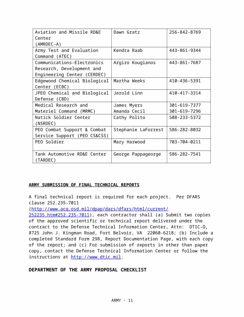
ARMY SBIR PROGRAM COORDINATORS (PCs) and Army SBIR 18.3 Topic Index
Participating Organizations PC Phone
Aviation and Missile RD&E Center(AMRDEC-A)
Dawn Gratz 256-842-8769
Army Test and Evaluation Command (ATEC)
Kendra Raab 443-861-9344
Communications-Electronics Research, Development and Engineering Center (CERDEC)
Argiro Kougianos 443-861-7687
Edgewood Chemical Biological Center (ECBC)
Martha Weeks 410-436-5391
JPEO Chemical and Biological Defense (CBD)
Jerold Linn 410-417-3314
Medical Research and Materiel Command (MRMC)
James MyersAmanda Cecil
301-619-7377301-619-7296
Natick Soldier Center (NSRDEC) Cathy Polito 508-233-5372
PEO Combat Support & Combat Service Support (PEO CS&CSS)
Stephanie LaForrest 586-282-8032
PEO Soldier Mary Harwood 703-704-0211
Tank Automotive RD&E Center (TARDEC)
George Pappageorge 586-282-7541
ARMY SUBMISSION OF FINAL TECHNICAL REPORTS
ARMY - 7
A final technical report is required for each project. Per DFARS clause 252.235-7011(http://www.acq.osd.mil/dpap/dars/dfars/html/current/252235.htm#252.235-7011), each contractor shall (a) Submit two copies of the approved scientific or technical report delivered under the contract to the Defense Technical Information Center, Attn: DTIC-O, 8725 John J. Kingman Road, Fort Belvoir, VA 22060-6218; (b) Include a completed Standard Form 298, Report Documentation Page, with each copy of the report; and (c) For submission of reports in other than paper copy, contact the Defense Technical Information Center or follow the instructions at http://www.dtic.mil.
DEPARTMENT OF THE ARMY PROPOSAL CHECKLIST
This is a Checklist of Army Requirements for your proposal. Please review the checklist to ensure that your proposal meets the Army SBIR requirements. You must also meet the general DoD requirements specified in the BAA. Failure to meet these requirements will result in your proposal not being evaluated or considered for award. Do not include this checklist with your proposal.
1. The proposal addresses a Phase I effort (up to $100,000 with up to a six-month duration) AND an optional effort (up to $50,000 for an up to four-month period to provide interim Phase II funding).
2. The proposal is limited to only ONE Army BAA topic.
3. The technical content of the proposal, including the Option, includes the items identified in Section 5.4 of the BAA.
4. SBIR Phase I Proposals have four (4) sections: Proposal Cover Sheet, Technical Volume, Cost Volume and Company Commercialization Report. The Technical Volume .pdf document has a 20-page limit including, but not limited to: table of contents, pages intentionally left blank, references, letters of support, appendices, technical portions of subcontract documents [e.g., statements of work and resumes] and all attachments). However, offerors are instructed to NOT leave blank pages, duplicate the electronically generated cover pages or put information normally associated with the Technical Volume in other sections of the proposal submission as THESE WILL COUNT AGAINST THE 20-PAGE LIMIT. Any information that details work involved that should be in the technical volume but is inserted into other sections of the proposal will count against the page count. ONLY the electronically generated Cover Sheet, Cost Volume and Company Commercialization Report (CCR) are excluded from the Technical Volume .pdf 20-page limit. As instructed in Section 5.4.e of the DoD Program BAA, the CCR is generated by the submission website, based on information provided by you through the “Company Commercialization Report” tool. Army Phase I proposals submitted with a Technical Volume .pdf document of over 20-pages will be deemed NON-COMPLIANT and will not be evaluated.
5. The Cost Volume has been completed and submitted for both the Phase I and Phase I Option and the costs are shown separately. The Army prefers that small businesses complete the Cost Volume form on the DoD Submission site, versus submitting within the body of the uploaded proposal. The total cost should match the amount on the cover pages.
6. Requirement for Army Accounting for Contract Services, otherwise known as CMRA reporting is included in the Cost Volume (offerors are instructed to include an estimate for the cost of complying with CMRA).
7. If applicable, the Bio Hazard Material level has been identified in the Technical Volume.
8. If applicable, plan for research involving animal or human subjects, or requiring access to government resources of any kind.
ARMY - 8
9. The Phase I Proposal describes the "vision" or "end-state" of the research and the most likely strategy or path for transition of the SBIR project from research to an operational capability that satisfies one or more Army operational or technical requirements in a new or existing system, larger research program, or as a stand-alone product or service.
10. If applicable, Foreign Nationals are to be identified in the proposal.
ARMY - 9
ARMY SBIR 18.3 Topic Index
A18-131 Epsilon Near Zero Optical LimiterA18-132 Method of Developing Helicopter Source Noise Models using Parameter Identification
TechniquesA18-133 Open Source High Assurance SystemA18-134 Incremental Partitioning to Minimize Upgrade Change ImpactsA18-135 Autonomous and Remote Refueling Grounding SystemA18-136 Autonomous and Remote Fuel Agitation, Filtration & CertificationA18-137 Shape Memory Alloy Heat EngineA18-138 Autonomous Flight Termination Analysis and Real Time Subsequent Debris ImpactsA18-139 Power Conditioning Surge Module for Standalone Power and Tactical MicrogridsA18-140 High Temperature Polymers for 3D Printed Injection Molding ToolingA18-141 Reducing Agglomeration of Explosively Disseminated Aerosol PowdersA18-142 Wearable medical device to diagnose in-theater opioid intoxication of the warfighterA18-143 Miniaturized, on-body delivery system of medical countermeasures for military operationsA18-144 Biodegradable Vector Control SystemA18-145 At-Home Minimally Invasive Tacrolimus Plasma Level Monitoring DeviceA18-146 Situational Awareness Sensors for Airdrop OperationsA18-147 Field Command Post Free Space Optical Communications (FSOC) Mesh NetworkA18-148 Rapid Expandable Mobile Shelter (REMS) for Mission CommandA18-149 Individual Soldier / Small Unit Desalination DeviceA18-150 Vision Enhancement for the Dismounted WarriorA18-151 Smart Hearing Protection for the Mounted & Dismounted WarriorA18-152 Biomimetic Human - Exoskeleton InterfaceA18-153 Small robot assured communications in complex RF environmentsA18-154 Local Wind Measuring DeviceA18-155 Intelligent Urgent StopA18-156 Armor support ring optimization
ARMY - 10
ARMY SBIR 18.3 Topic Descriptions
A18-131 TITLE: Epsilon Near Zero Optical Limiter
TECHNOLOGY AREA(S): Electronics
OBJECTIVE: The objective of this task is to investigate the novel interaction of electromagnetic radiation with materials that have the dielectric constant close to zero, with the specific aim to understand and thereby enhance the nonlinear interactions for applications in optical limiting for sensor protection.
DESCRIPTION: A long standing application of nonlinear optics is that of optical limiting for sensor protection. Progress in this area has been hampered by the ultrafast materials available which until recently had very small nonlinear coefficient. Slow nonlinear devices can have large nonlinearities but these are not usefully because several optical pulses are needed before the limiting process engages. Recent research on nonlinear Epsilon Near Zero, ENZ, materials have demonstrated that these materials have the potential to overcome these problems to finally bring efficient optical limiters to fruition.
A recent experimental result on the nonlinear optical response of an ENZ material showed not just a large nonlinearity, but an unprecedented nonlinear response which could have implications for many nonlinear devices [1]. In particular, it was noted that for a given change in the permittivity, the resulting change in the refractive index for a lossless material is related to the inverse square root of the dielectric constant.
Therefore, the change in refractive index becomes large as the permittivity becomes small, suggesting that the ENZ frequencies of a material system should give rise to strong nonlinear optical properties. The experimentally observed change in the real part of index of refraction near the ENZ frequency of Indium Tin Oxide (ITO) was measured to be 0.7 or 170% of the linear index and had a response time on the order of a few hundred femtoseconds. Until now, typical changes in the index of refraction for ultrafast nonlinear materials were <1%. The work on ITO was quickly followed by another measurement on a transparent semiconductor similar to ITO, Al doped ZnO [2]. Like the ITO, the ZnO had an ultrafast nonlinear index change close to unity.
In practical terms, the nonlinear optical properties of an ENZ material can in principle become very large and dominate linear optical properties even at what may be considered moderate intensities, or a few megawatts per centimeter squared (MW/cm^2). In general the onset of the nonlinearity will depend on how close to zero the linear dielectric constant can be designed, via doping, material processing, or a combination of both. For instance, the ENZ crossing point of ITO changes depends on annealing temperatures. Then, if for example, the minimum magnitude of the linear dielectric constant were of order 0.01, then one might expect a boost of the local field intensity inside the ENZ material by a factor of 100, which could reduce needed threshold intensities by similar factors. Therefore, while typically tens of gigawatts per centimeter squared (GW/cm^2) may be needed to trigger the nonlinearity in ordinary materials, only tens of MW/cm^2 or less may suffice to activate the nonlinearity of an ENZ material, opening the door to lower thresholds and practical devices.
In addition to the ENZ conducting oxides, it is possible to fabricate metamaterial ENZ’s [3-4]. While little work has been done on the nonlinear properties of metamaterial ENZ’s it is likely that these will possess large and ultrafast nonlinear optical responses. The potential application of ENZ metamaterials will allow the frequency of the ENZ point to be designed and not limited by material properties of the constituents. It may also possible to use either a metamaterial or a coupled, multi-resonance approach to flatten the dispersion curve, thereby having a broadband nonlinear optical response.
PHASE I: Demonstrate a feasible design of an optical limiter based on the nonlinear properties of a conducting oxide ENZ material or an ENZ metamaterial. The device should be designed with optimal linear transmittance and an order of magnitude modulation for optical limiting.
PHASE II: Demonstrate a working ENZ optical limiter for operation in the near-infrared or mid-infrared. In addition to optimizing the dynamic range and throughput as in Phase I, the second phase shall focus on minimizing device
ARMY - 11

volume and including parameters related to environmental temperature changes and impact resistance.
PHASE III DUAL USE APPLICATIONS: Dual Use Applications: Materials with large and fast optical nonlinearities have numerous applications including white light generation, optical frequency combs, harmonic generation, sensor protection and many others. All these applications are strongly material dependent and would benefit from materials with larger nonlinearities than those presently available.
REFERENCES:1. M.Z. Alam, I. De Leon, R.W. Boyd, “Large optical nonlinearity of ITO in its ENZ region,” Science 352, 798 (2016).
2. L. Caspani, et al., “Enhanced nonlinear refractive index in ENZ materials,” Phys. Rev. Lett. 116, 233901 (2016).
3. P. Moitra, et al., “Realization of an all dielectric zero index optical metamaterial,” Nature Photonics 7, 791 (2013).
4. J. Gao, et al., “Experimental realization of ENZ metamaterial slabs with metal- dielectric multilayers,” Appl. Phys. Lett. 103, (2013).
KEYWORDS: nonlinear optics, epsilon near zero, metamaterial, optical limiting, sensor and eye protection
A18-132 TITLE: Method of Developing Helicopter Source Noise Models using Parameter Identification Techniques
TECHNOLOGY AREA(S): Air Platform
OBJECTIVE: Develop a semiempirical tool for generating time-domain based, nondimensionally scaled, acoustic spheres from limited flight test data.
DESCRIPTION: Accurate helicopter source noise models are required by the US Army in order to estimate the acoustic impact of proposed helicopter operations. Conventional helicopter source noise models used by current mission planning tools are empirical in nature, relying on measurements of helicopter noise captured by ground based microphone arrays during steady flyovers [1-2]. These models are entirely empirical, which limit their capability to estimate the noise produced by the helicopter at operating conditions inside the limited measurement database. Therefore, inaccurate estimates are provided when vehicle operations occur at different altitudes, gross weights, and external store configurations than those measured. These models are further incapable of accurately predicting effects of maneuvering flight conditions that are difficult to measure with a ground-based array.
First-principles helicopter noise prediction models exist, but do not have the validated accuracy sufficient to produce reliable estimates of helicopter noise spheres required by mission planners. This topic proposes the development of a time-domain based hybrid method, where a mid-fidelity helicopter aeroacoustic prediction method is calibrated to measured data using a parameter identification approach. Accuracy comparable to empirical models is assured by calibrating the model to the available data; however, the model can be applied to predict noise at conditions that were not measured because it contains a physical model of the helicopter noise sources.
Prior research has proven the viability of this concept through the development of the Fundamental Rotorcraft Acoustic Modeling from Experiments (FRAME) method of developing source noise models for helicopters and other rotorcraft [3]. The FRAME technique has been used to make accurate helicopter noise predictions from limited sets of vehicle data; for example, validated predictions have been made at different airspeeds, descent rates [4], and density-altitudes [5]. Validated predictions have also been made for a variety of horizontal and vertical maneuvers with load factors ranging from 0.5 g to 2 g [6]. However, the FRAME software is at a low TRL and is primarily oriented towards community noise prediction. The goal of this proposed topic is to prompt the development of a commercial source noise modeling method that can support acoustic predictions for civilian and
ARMY - 12

military helicopter operations.
PHASE I: The objective of phase I is to create a proof-of-concept semiempirical tool for generating, time-domain based, nondimensional scaled acoustic data for an isolated main rotor using wind tunnel acoustic measurements, or flight test measurements, as the source of model calibration data. Validate the tool by demonstrating that when the tool is calibrated to a subset of the measured data, the tool can accurately predict the time-domain main rotor harmonic noise radiation for rotor operating conditions both inside of (interpolation) and outside of (extrapolation) the range of data used to calibrate the tool. Develop technology transition plan and initial business case analysis.
PHASE II: The objective of phase II is to further develop the tool to accurately model the acoustics of helicopters in free flight. Extend the tool to produce rotor harmonic time-domain noise data for both the main and tail rotors. Develop a method to calibrate the tool using ground-based microphone acoustic data collected during the flight testing of helicopters. Validate the tool by demonstrating that when the tool is calibrated to a subset of measured data, accurate rotor harmonic noise predictions can be made for flight conditions both inside of and outside of the range of calibration data. Extend the tool to generate acoustic data spheres suitable for use as input to existing acoustic propagation software used to assess the acoustic impact of helicopter operations. Refine transition plan and business case analysis.
PHASE III DUAL USE APPLICATIONS: The objective of phase III is to further validate and finalize the tool for routine use in Government and commercial applications. Incorporate noise predictions for non-rotor-harmonic noise sources, such as broadband and engine noise. Validate the tool by demonstrating that accurate noise predictions can be made under atmospheric conditions different from those under which the calibration data were collected. Validate the tool by demonstrating that accurate noise predictions can be made under maneuvering flight using only steady flight noise data for calibration. Integrate the tool with a user interface and develop end-user documentation. The resulting tool is applicable to both military and commercial rotorcraft. Key military applications include predicting vehicle acoustic footprints during flight operations. The validated tool will be useful for accurate land use models for both military and civilian community operations.
REFERENCES:1. Lucas, M. J. and Marcolini, M. A., “Rotorcraft Noise Model,” AHS Technical Specialists’ Meeting, Williamsburg, VA, October 1997.
2. Conner, D. A. and Page, J. A., “A Tool for Low Noise Procedures Design and Community Noise Impact Assessment: The Rotorcraft Noise Model (RNM),” Heli Japan, Tochigi, Japan, 2002.
3. Greenwood, E., Fundamental Rotorcraft Acoustic Modeling from Experiments (FRAME). Ph.D. University of Maryland, 2011.
4. Greenwood, E., and Schmitz, F.H., "A Parameter Identification Method for Helicopter Noise Source Identification and Physics-Based Semi-Empirical Modeling," presented at the American Helicopter Society 66th Annual Forum, Phoenix, AZ. May 2010.
5. Greenwood, E., Sim, B.W., and Boyd, D.D., "The Effects of Ambient Conditions on Helicopter Harmonic Noise Radiation: Theory and Experiment," presented at the American Helicopter Society 72nd Annual Forum, West Palm Beach, FL. May 2016.
6. Greenwood, E., Rau, R., May, B., and Hobbs, C., "A Maneuvering Flight Noise Model for Helicopter Mission Planning," presented at the American Helicopter Society 71st Annual Forum, Virginia Beach, VA. May 2015.
KEYWORDS: Rotorcraft, Helicopter, Acoustics
A18-133 TITLE: Open Source High Assurance System
ARMY - 13

TECHNOLOGY AREA(S): Electronics
OBJECTIVE: Current commodity computer hardware and software are proprietary. A thorough security review cannot be performed on systems with undisclosed components. Offeror shall research high assurance computer security based on a completely open hardware and software platform following Saltzer and Schroeder’s open design principles from 1975.
DESCRIPTION: Today's Aviation systems are based on computer architectures that were not designed with security as a requirement … leading to inherent vulnerabilities in both hardware and software that add significant air worthiness and mission risk. Embedded system designs are typically based on commodity hardware optimized almost exclusively for speed – not security – leading to critical cyber vulnerabilities [1] that can have devastating effects on safety and mission effectiveness. This has also led to the unsustainable “Perimeter, Patch, Pray” Information Assurance strategy that is simply impractical for fielded aviation and missile systems.
Commodity hardware is proprietary. It is difficult to impossible to perform a thorough security review, when the hardware implementation is not provided. The Illinois Malicious Processor [2] illustrates the security issues from an undisclosed design.
Saltzer and Schroeder in 1975 [3] stated that the design for a secure computer system should not be “secret”. “Open design: The hardware design should not be secret. The mechanisms should not depend on the ignorance of potential attackers, but rather on the possession of specific, more easily protected, keys … ” In 1883, Kerckhoff [4] made a similar statement for secret codes: “It [the system] should not require secrecy, and it should not be a problem if it falls into enemy hands.”
Current computer architectures are based on proprietary hardware and software. In terms of Saltzer and Schroeder, the design is “secret.” Proprietary hardware and software prevents a thorough security review. With a completely open hardware and software system, a thorough security review is possible. Recent developments in machine generated formal proofs provides automatic formal high assurance statements. The Army needs open hardware and software architectures that provide for high performance, rigorous security reviews, and high assurance computer security.
Recent developments in the open source hardware and software communities have provided the open source microprocessor, the RISC-V [5]-[8], and a formally verified, open source operating system, seL4 (secure extended L4) [9]-[12]. RISC-V is well-established with HDL code and a complete set of software development tools. The seL4 microkernel has a 20 year development history [12]. seL4 is a microkernel with 8,700 lines of C code and 600 lines of assembly code [11]. A machine generated formal proof-of-correctness demonstrates a high computer assurance level for seL4. RISC-V and seL4 are two open source examples; offeror is free to consider other hardware and OS open source components.
PHASE I: For the Phase I proposal, offeror shall describe the feasibility of creating a high assurance open computer hardware and software architecture based on the “open design principles” from Saltzer and Schroeder in 1975 [3]:(1) Propose open source hardware and open source OS for a high assurance system.(2) describe the project development tools;(3) provide a plan to achieve an Evaluation Assurance Level Six (EAL6) [13] or higher rating for the operating system;(4) describe potential Army Applications (Joint Multi-Role Technology Demonstrator [16]) and commercial applications; and(5) provide a business model to market the proposed system.
For the phase I effort, the offeror shall demonstrate the feasibility and security benefits of creating a high assurance open computer hardware and software architecture based on the “open design principles” from Saltzer and Schroeder in 1975 [3].(1) Develop models, simulations, prototypes, etc. to determine technical feasibility of developing a high assurance (EAL6 [13]) computer system based on open source hardware and an open source operating system;(2) deliver an Architecture Description and Requirements Specification Report; and(3) deliver an EAL6 Certification Plan Report.
ARMY - 14
PHASE II: Offeror shall develop a high assurance computer system based on the “open design principles” from Saltzer and Schroeder [3] and offeror’s proposal and phase I effort. It is highly recommended that the offeror team with a government prime contractor. The offeror shall demonstrate high assurance computer system running an Army application (Joint Multi-Role Technology Demonstrator [16]). The Offer shall propose potential applications for a system demonstration and implement an application with government concurrence.
Offeror shall deliver a year 1 report and a year 2 report describing artifacts, documents, verification tests, etc. completed following the plan in the Phase I document "EAL6 Certification Plan Report." Offeror shall deliver 2 prototype systems to the government point of contact for test and evaluation with all software tools and licenses (if required) to build and use the system. Offeror shall provide 2 days of on-site training for the system.
PHASE III DUAL USE APPLICATIONS: Offeror will develop and market high assurance hardware/OS system based on phase II development work and marketing plan from phase I. Offeror will achieve EAL6 [13] for high assurance computer system. Offeror will integrate high assurance hardware/OS system into an Army Aviation subsystem currently under development or via technology refresh.
REFERENCES:1. P. Jungwirth, et al.: "Cyber defense through hardware security", Proc. SPIE 10652, Disruptive Technologies in Information Sciences, 106520P (9 May 2018); doi: 10.1117/12.2302805; https://doi.org/10.1117/12.2302805
2. S. King, et al.: “Designing and implementing malicious hardware,” University of Illinois at Urbana Champaign, Urbana, IL 61801, 2008.
3. J. Saltzer and M. Schroeder: “The protection of information in computer systems,” Proceedings of the IEEE, 63(19):1278-1308, Sept. 1975.
4. https://en.wikipedia.org/wiki/Kerckhoffs%27s_principle
5. https://riscv.org/
6. Wikipedia: RISC-V, https://en.wikipedia.org/wiki/RISC-V
7. CHISEL: Constructing Hardware in a Scala Embedded Language, https://chisel.eecs.berkeley.edu/
8. A. Waterman, et. al. "The RISC-V Compressed Instruction Set Manual Version 1.9 (draft)" (PDF). RISC-V. https://riscv.org/wp-content/uploads/2015/11/riscv-compressed-spec-v1.9.pdf
9. seL4 microkernel. https://github.com/seL4/seL4
10. Wikipedia.org: “L4 microkernel family.” https://en.wikipedia.org/wiki/L4_microkernel_family
11. G. Klein., et al.: “seL4: formal verification of an OS kernel,” Proceedings of the ACM SIGOPS 22nd symposium on Operating systems principles, Big Sky, Montana, pp. 207-220, October 11 - 14, 2009.
12. K. Elphinstone and G. Heiser: "From L3 to seL4 what have we learnt in 20 years of L4 microkernels?," ACM Symposium on Operating Systems Principles Farmington, PA, pp. 133-150, 03 - 06 November 2013.
13. Wikipedia.org: “Evaluation Assurance Level,” https://en.wikipedia.org/wiki/Evaluation_Assurance_Level
14. W. Keegan: “Separation Kernels Enable Rapid Development of Trustworthy Systems,” COTS Journal, pp. 1-3, February 2014. www.lynx.com/pdf/Separation_Kernels_Enable_Rapid_Development.pdf
15. C. Herley and P.C. van Oorschot: "SoK: Science, Security, and the Elusive Goal of Security as a Scientific Pursuit," Microsoft Research and Carleton University, 2017.
ARMY - 15
16. http://www.defenseinnovationmarketplace.mil/resources/JMR_AMRDEC01.pdf
KEYWORDS: open source, RISC-V, seL4, high assurance, safety critical, aerospace, cybersecurity, operating system
A18-134 TITLE: Incremental Partitioning to Minimize Upgrade Change Impacts
TECHNOLOGY AREA(S): Air Platform
OBJECTIVE: Develop a capability for analyzing the ripple effects of incrementally updating architectural models of mission systems specified in the SAE 5506 Architecture Analysis & Design Language (AADL) and/or the Object Management Group Systems Modeling Language (SysML) in a manner that allows a user to understand and minimize the recertification impact of the architectural model change. The capability should be integrated with current model-based tools that automatically generate and analyze integration and configuration data.
DESCRIPTION: A major reason that system upgrades are so expensive in aviation systems is that all changes to the system must be recertified. Changes to a few components may have broad impact across the entire system, requiring more time, money, and effort to recertify large portions of the system than if those impacts could be constrained to the few components that are changed.
The Army is interested in generating integration and configuration data from model based sources that specify the software/hardware/system architecture of safety and security critical partitioned aviation mission systems in AADL or SysML. Many tools are available that are effective in configuring and generating this data for initial deployment. However, they are not currently change aware. That is, changes to the AADL or SysML model will result in a wholly new set of data the next time the tool is run without any measurement or analysis of the effect of those changes with respect to how many parts of the overall system will be affected. A broader approach to these generation and analysis tools that addresses safety and security certification is needed. The expectation is that multiple existing tools will be extended and integrated rather than a single new tool developed.
By making these tools change aware, certification impacts can be mitigated. For example, a tool that generates real-time schedules that is not change aware may alter the scheduling of every partition on the system to produce a new schedule when a new component is added or swapped out. This results in the entire schedule needing to be reevaluated and the entire system retested. A change aware scheduling tool could, for example, instead generate a schedule that adds the new component in a way that minimizes the changes to other component schedules. Then only the new component and those changes need to be examined, as the others will retain the same schedule and guarantees that were previously certified. This reduces recertification costs and time. Furthermore, with such a capability (keeping with the scheduling example), schedules could be generated for initial deployment that could already be more robust against these sorts of changes.
AADL or SysML model-based analysis tools can be made change aware as well. For example, a tool that analyzes an AADL model to determine compliance with Multiple Independent Levels of Security (MILS) requirements could be extended so as to be able to show that an unchanged partition in an altered system cannot send or receive any new data, despite new (compliant) information flows being added elsewhere.
PHASE I: Develop and demonstrate the feasibility of at least one change aware AADL and/or SysML model-based tool. Integrate a basic incremental update capability into an existing tool and show how it improves output from a change minimization perspective.
PHASE II: Based on Phase I effort, develop and demonstrate robust capabilities for updating model-based tools to be change aware. These updated tools should minimize change effects across a broad range of tool outputs, such as schedules, information flows, and isolation. Demonstrate updated change aware tools that identify which components need to be reevaluated and recertified between runs of data generating tools.
PHASE III DUAL USE APPLICATIONS: Apply change aware model-based tools to an Army platform in development. Mature tools to a level where they can be used in platform development by the Army and private
ARMY - 16
sector. While the Army Aviation is interested in change aware tools, this technology is broadly applicable to all participants in the acquisitions pipeline. Performers from component developers to system integrators can all make use of such tools to reduce costs in system development for all parties involved.
REFERENCES:1. Challenges for an Open and Evolutionary Approach to Safety Assurance and Certification of Safety-Critical Systems, Huáscar Espinoza et al, 2011.
2. Verification of Cyber-Physical Systems, Majumdar, Murray, and Prabhakar, 2014.
3. Survey of Model-Based Systems Engineering (MBSE) Methodologies, Jeff A. Estefan, Jet Propulsion Laboratory, California Institute of Technology, 2008.
4. Evidence Based Certification: The Safety Case Approach, Kelly, High Integrity Systems Engineering Group, University of York, 2008.
5. SAE AS 5506B, “Architectural Analysis and Design Language (AADL)”, Sept 2012
6. OMG SysML version 1.5, May 2017
KEYWORDS: Model Based Engineering (MBE), Model Based Systems Engineering (MBSE), Architecture Centric Virtual Integration Process (ACVIP), Architectural Analysis and Design Language (AADL), SysML.
A18-135 TITLE: Autonomous and Remote Refueling Grounding System
TECHNOLOGY AREA(S): Air Platform
OBJECTIVE: The Autonomous and Robotic Remote Refueling Point (AR3P) concept is a project addressing the range and on-station time limitations and mission risks faced by current military Rotary Wing (RW) aircraft. The AR3P project is an Operational Energy initiative for Aviation Refueling led by the US Army Aviation and Missile Research, Development, and Engineering Center (AMRDEC) as a means to reduce soldier exposure and reduce demand for fuel on the battlefield. As part of this effort a capability gap has been identified in currently available Commercial-off-the-shelf (COTS) and Government-off-the-shelf (GOTS) technology to achieve remote and autonomous electrical grounding. This effort will be focused on closing that gap.
DESCRIPTION: The AMRDEC has been pursuing the AR3P platform through a partnership between its Aviation Development Directorate and its Operational Energy Lab. The initial concept for the AR3P concept has been demonstrated but has identified capabilities gaps in some technical areas, with specific gaps in grounding each of the subsystems as well as establishing a ground with the aircraft prior to fuel transfer. In this SBIR, feasibility and maturation of an autonomous and remote electrical grounding approach is needed to enable the ability of executing an autonomous fueling mission with no human-in-the-loop. At present, there is no means of remotely establishing an earth ground IAW specifications delineated in MIL-HDBK-419B – Grounding, Bonding, and Shielding for Electronic Equipment and Facilities. This effort will address the physical complexity, engineering, and solutions development need to achieve the stated goal. All innovative solutions will be pursued as a part of this effort to include new system design, COTS, GOTS, and other engineering solutions.
At present, no known system is available to accomplish the holistic objective set forth in this SBIR. This effort will address the technical solution itself, size, transportability, component availability, and engineering complexity and simplicity.
PHASE I: Conduct a detailed feasibility analysis of the grounding and refueling AR3P target system for the Apache aircraft and determine likelihood of success for grounding the system and aircraft utilizing COTS, GOTS, or new system design to be compliant with all government regulations. Demonstrate that the stated goal is achievable and lay out next steps for development, design, and implementation of autonomous aircraft and system grounding.
ARMY - 17
Period of performance of the Phase I effort is to be 6 months.
PHASE II: Based on the outcomes of Phase I, implement initial prototype design, development, build, and test for the subject system or integrate the COTS/GOTS systems identified in Phase I into the overall system. Careful focus will be placed on engineering complexity and integration of grounding solution into overall system that solves the subject challenge.
PHASE III DUAL USE APPLICATIONS: The development of an autonomous electrical grounding system will be utilized for next generation Army Aviation fueling operations and could also be leveraged across services to both the Air Force and Navy in multiple domains from Aviation to land vehicles and ships. Search and Rescue operations conducted by Homeland Security, National Parks Service, and the US Coast Guard could leverage this technology in a variety of environments where human intervention is not possible and remote operations are required. In the commercial sector, there is opportunity in the commercial aviation and shipping industry when these assets are operated in remote locations. The technology developed here would reduce the need for human intervention thereby removing people from potentially remote or harmful environments while extending the range and effectiveness of existing airborne, land vehicles, and ship platforms to support remote operations.
REFERENCES:1. “Hot refuels keep aircraft flying,” https://www.army.mil/article/37556/hot_refuels_keep_aircraft_flying.
2. “Marine Aviation Hot Refueling,” https://todaysmilitary.com/videos/marine-aviation-hot-refueling.
3. “Earthing and Bonding of Aircraft and Ground Support Equipment,” AC 21-99 Aircraft Wiring and Bonding, Sect 2 Chap 14.
KEYWORDS: autonomous, remote, electrical grounding, refueling, Operational Energy, Future Vertical Lift (FVL), expeditionary maneuver, mobility.
A18-136 TITLE: Autonomous and Remote Fuel Agitation, Filtration & Certification
TECHNOLOGY AREA(S): Air Platform
OBJECTIVE: The Autonomous and Robotic Remote Refueling Point (AR3P) concept is a project addressing the range and on-station time limitations and mission risks faced by current military Rotary Wing (RW) aircraft. The AR3P project is an Operational Energy initiative for Aviation Refueling led by the US Army Aviation and Missile Research, Development, and Engineering Center (AMRDEC) as means to reduce soldier exposure and reduce demand for fuel on the battlefield. As part of this effort a capability gap has been identified in currently available Commercial-off-the-shelf (COTS) and Government-off-the-shelf (GOTS) technology to achieve remote and autonomous agitation and certification of aviation fuel. This effort will be focused on closing that gap.
DESCRIPTION: The AMRDEC has been pursuing the AR3P platform through a partnership between its Aviation Development Directorate and its Operational Energy Lab. The initial concept has been demonstrated but has identified capabilities gaps in some technical areas, with specific gaps in fuel agitation and certification. In this SBIR, feasibility and maturation of an autonomous and remote fuel agitation and certification approach is needed to determine the feasibility of executing autonomous fueling mission with no human-in-the-loop. At present remote certification would not meet the requirements laid out in Army Techniques Publication (ATP) 3.04.94. Technology opportunities identified for application to the AR3P during this effort will be mapped to the requirements laid out in ATP 3.04.94 as well as ATP 4.43 which focuses on fuel agitation, filtration and quality. This effort will address the physical complexity, engineering, and solutions development needed to achieve the stated goal. All innovative solutions will be pursued as a part of this effort to include new system design, COTS, GOTS, and other engineering solutions.
At present, no known system is available to accomplish the holistic objective set forth in this SBIR. This effort will address the technical solution itself, size, transportability, component availability, and engineering complexity and
ARMY - 18
simplicity.
PHASE I: Conduct a detailed feasibility analysis of the system end state goal and determine likelihood of success utilizing COTS, GOTS, or new system design. Demonstrate that the stated goal is achievable and lay out next steps for development, design, and implementation of autonomous and remote fuel agitation, filtration & certification. Period of performance of the Phase I effort is to be 6 months.
PHASE II: Based on the outcomes of Phase I, implement initial prototype design, development, build, and test for the subject system or integrate the COTS/GOTS systems identified in Phase I into the overall system. Careful focus will be placed on engineering complexity, proprietary system interface (meaning use of the subject system with other currently in use systems that may be proprietary in nature with little to no opportunity for modification), and creating a solution that solves the subject challenge.
PHASE III DUAL USE APPLICATIONS: The development of a remote fuel agitation, filtration, and certification system will be utilized for next generation Army Aviation fueling operations and could also be leveraged across service to both the Air Force and Navy in multiple domains from Aviation to land vehicles and ships. Search and Rescue operations conducted by Homeland Security, National Parks Service, and the US Coast Guard could leverage this technology in a variety of environments where human intervention is not possible and remote operations are required. In the commercial sector, there is opportunity in the commercial aviation and shipping industry when these assets are operated in remote locations. The technology developed here would reduce the need for human intervention and remove people from remote or potentially harmful environments while extending the range and effectiveness of existing airborne platforms to support remote operations.
REFERENCES:1. Army Techniques Publication (ATP) 3.04.94 - Army Techniques Publication for Forward Arming and Refueling Points
2. Army Techniques Publication (ATP) 4.43 - Petroleum Supply Operations
KEYWORDS: autonomous, remote, refuel, fuel, certification, filtration, agitation
A18-137 TITLE: Shape Memory Alloy Heat Engine
TECHNOLOGY AREA(S): Air Platform
OBJECTIVE: Design, model and demonstrate a shape memory alloy engine with efficiency approaching 50% of Carnot's limit that converts the waste thermal energy with low temperature gradients to power applications on an aviation platform.
DESCRIPTION: Structural health monitoring sensors (acoustic, optical, piezoresistive, etc.) are currently either powered by batteries or directly through a central power supply. This creates a challenge in their long term deployment as batteries will have to be changed periodically and in mobility as wiring becomes cumbersome. In an ideal scenario, low power consuming sensors could be developed, for structural health monitoring and feedback control on aviation platforms, which can be directly powered through energy source available in the environment. One such energy source is low-temperature gradients. Although low-grade heat (hot-side temperature <50oC) is available in variety of places, current thermal energy harvesting technologies, primarily thermoelectric generators, have low efficiency at these low temperature gradients to be cost-effective. Shape memory alloy (SMA) engine provides transformative pathway to harness the abundant low temperature gradients, thereby, opening the possibility to implement self-powered sensors in variety of scenarios. This technology can provide options to increase the flight time and safety of missions in the expanded battlefield within contested air space in accordance with the Army Modernization plan for future vertical lift platforms.
Thermoelectric generator (TEG) is the most widely used heat recovery system that competes with the SMA engine,
ARMY - 19

since both convert thermal energy into electrical power. However, recent results indicate that SMA technology can efficiently work at very low thermal gradients (10K gradient at hot-side temperature of 323K) by chosing alloys with low phase transformation (PT) temperatures and a small hysteresis. At these low temperature gradients, TEGs are not efficient. A variety ofdesigns have been suggested in literature for SMA heat engines since the discovery of these alloys. , However, most heat engine prototypes suffer from drawbacks including (i) necessity of large separation between the hot and cold sources, (ii) remarkable degradation in the efficiency as the heat engine runs for longer times (high fatigue), and (iii) low power conversion efficiency. All these past approaches are based on TiNi SMA wires. In order to overcome the known drawbacks, new prototype of SMA engines are required that utilizes the optimized material composition, and thermal transport through air and fluid. The prime goal of this program is to design, model and demonstrate SMA engine with high efficiency approaching 50% of Carnot’s limit. The new SMA engine design should provide large power density and efficiency at small temperature gradients, and demonstrate ultra-high life-time by using ternary or quaternary SMAs. The design focus should be on developing a small system that easily converts waste thermal energy of all forms (conduction, convection and radiation) into electrical energy. Thermal energy assessment on the aviation platforms (aircraft, helicopter, UAVs, docking, etc.) should be included in the analysis.
PHASE I: Identify SMA material composition that demonstrates PT around room temperature and exhibits low hysteresis and high fatigue life.; (b) Design and model the SMA engine architecture that demonstrates power density greater than 50W/kg and efficiency approaching 50% of Carnot’s limit; (c) Develop system-level mathematical model that combines all the parameters representing materials, mechanical friction, frequency of operation, thermal transport, and mode of heat transfer; (d) Demonstrate feasibility of the newly designed SMA engine concept. Identify key requirements for validating the self-powered structural health monitoring sensor node using 10oC temperature gradients, potential challenges, accuracy, limitations and approach for Phase II demonstration. Reliability and durability analysis on SMA engine should be included in the report. Evaluation criterion for Phase I report will include feasibility of the SMA engine design to meet weight, size, efficiency, power density and reliability requirements.
PHASE II: (i) Characterize the electrical, mechanical and thermal properties of the SMA composition over the wide range of temperatures. Demonstrate SMA composition with phase transformation occurring below 40oC while exhibiting achievable strain above 3.5%. (ii) Demonstrate SMA material manufacturing capability using thin film technology (magnetron sputtering, photolithography, wet etching, rapid thermal annealing, surface finishing) that can be scaled and deployed for manufacturing textured wires of lengths larger than 8 inches. (iii) Develop a fully functional and packaged SMA heat engine with power density greater than 65W/kg that can operate below hot-side temperature of 40oC and ambient cold-side around 25oC. (iv) Perform comparative analysis of the new SMA engine with respect to the traditional thermal generators in terms of efficiency, weight and size. (v) Demonstrate continuous powering of wireless structural health monitoring sensors through SMA engine. (vi) Perform reliability analysis through accelerated field tests under the realistic platform conditions.
PHASE III DUAL USE APPLICATIONS: Demonstrate the gain achieved in terms of lower weight and size (at least 25%) through the use of new SMA composition and device architecture. Develop potential transition partners including Army, other DoD agencies, and U.S. industrial sector for transitioning developed power source.
REFERENCES:1. A. D. Johnson - US Patent 4,055,955 (1977); J. J. Pachter - US Patent 4,150,544 (1979); D. J. Sandoval - US Patent 4,010,612 (1977); F. E. Wang - US Patent 4,275,561 (1981).
2. D. Avirovik, A. Kumar, R. J. Bodnar and S. Priya, “Remote light energy harvesting and actuation using shape memory alloy—piezoelectric hybrid transducer,” Smart Materials and Structures, 22, 052001 (2103).
3. Y. Sato, N. Yoshida, Y. Tanabe, H. Fujita and N. Ooiwa, “Characteristics of a new power generation system with application of a Shape Memory Alloy Engine,” Electrical Engineering in Japan, 165, 8-15 (2008).
ARMY - 20

4. Chluba, C.; Ge, W.; Lima de Miranda, R.; Strobel, J.; Kienle, L.; Quandt, E.; Wuttig, M. “Shape memory alloys. Ultralow-fatigue shape memory alloy films,” Science, 348, 1004-1007 (2015).
KEYWORDS: Thermal power, Heat engine, Wireless sensors, Structural health monitoring
A18-138 TITLE: Autonomous Flight Termination Analysis and Real Time Subsequent Debris Impacts
TECHNOLOGY AREA(S): Electronics
The technology within this topic is restricted under the International Traffic in Arms Regulation (ITAR), which controls the export and import of defense-related material and services. Offerors must disclose any proposed use of foreign nationals, their country of origin, and what tasks each would accomplish in the statement of work in accordance with section 5.4.c.(8) of the Announcement.
OBJECTIVE: Develop a real-time debris pattern estimation and destruct prediction software which influences autonomous destruct decisions. Predictions are based on pre-flight rules, ground mapping and navigation information from multiple measured sources.
DESCRIPTION: Long Corridor, extended range missile flights will outpace man-in-the-loop command destruct and Continental United States Major Range and Test Facility Base capability in the near future, primarily due to infrastructure lacking along multi-state corridors. Flight termination of errant ground launched missiles will rely on autonomous decisions from the munition itself. A software platform is needed that will take data from various and redundant missile inputs, for example inertial measurement units, global positioning systems and accelerometers, along with pre-loaded flight trajectories and calculate a real-time debris pattern overlaid onto a ground map that will depict debris fallout. Being a long corridor flight, a potential exists that the debris fallout will be within populated areas. The software should also provide calculations as to the real-time missile flight accuracy and the optimal timing of flight termination initiation that would result in minimal debris fallout and collateral damage over populated areas and roadways, to include the consideration of environmental effects (i.e. weather patterns). The software platform and resultant mapping will reside within the flight termination system on the missile itself and should be capable of fault tolerance. The associated graphical tool will be used to pre-populate certain criteria such as intended flight paths and measured debris effects.
PHASE I: Develop a feasibility study that consist of a high level software concept that includes identification of necessary measurements, overall proposed functionality, and preliminary mapping solution along with identifying the data rate necessary for transmission of subsequent information to a ground based receiving station.
PHASE II: Develop and demonstrate a prototype solution in a realistic environment. Conduct testing to prove feasibility over extended operating conditions.
PHASE III DUAL USE APPLICATIONS: This software platform could be used in a broad range of military and civilian aeronautical applications where debris fallout and real time mapping and visualization are necessary for high altitude/rapidly accelerating trajectories – for example, in commercial air space and space vehicle launches. The test and evaluation phase of extended range munitions, such as Long Range Precision Fires, and subsequent stock pile reliability testing of fielded munitions will require this software platform.
REFERENCES:1. Bull, James B, and Raymond J Lanzi. “An Autonomous Flight Safety System.” Defense Technical Information Center, NATIONAL AERONAUTICS AND SPACE ADMINISTRATION WALLOPS ISLAND VA WALLOPS FLIGHT CENTER, Nov. 2008, www.dtic.mil/dtic/tr/fulltext/u2/b348954.pdf.
ARMY - 21
2. Range Commanders Council, "Global Positioning and Inertial Measurements Range Safety Tracking Systems' Commonality Standard," RCC 324
3. Range Commanders Council, "Flight Termination Systems Commonality Standard," RCC 319
KEYWORDS: autonomous flight termination, extended range munition, mapping software, debris pattern, visualization
A18-139 TITLE: Power Conditioning Surge Module for Standalone Power and Tactical Microgrids
TECHNOLOGY AREA(S): Materials/Processes
ACQUISITION PROGRAM: PEO Command, Control and Communications Tactical
OBJECTIVE: Design and develop a Power Conditioning Surge Module (PCSM) capable of enabling of military power systems to better handle non-linear loads and power surges in excess of 125% rated power for 3 to 5 seconds. Military generator sets are typically oversized to handle surge loads and inrush currents which can exceed 200-300% of the generator’s rated power. Since over-sizing a generator set is both wasteful in terms of fuel consumption, and detrimental to the generator’s reliability and lifespan, the goal is to enable end users to “right size” their generator sets in accordance with the average load power—not peak power requirements.
DESCRIPTION: The Army is in need of a power dense surge module that can be used with any military generator set and enable it to handle non-linear loads and power surges greater than or equal to 125%. A load is considered non-linear if its impedance changes with the applied voltage. The changing impedance means that the current drawn by the non-linear load will not be sinusoidal even when it is connected to a sinusoidal voltage. These non-sinusoidal currents contain harmonic currents that interact with the impedance of the power distribution system to create voltage distortion that can affect both the distribution system equipment and the loads connected to it. Examples of harmonic producing loads are Switch-Mode Power Supplies (SMPS), AC or DC motor drives, inverters, DC converters, etc. Higher frequency harmonic currents flowing through power systems can cause communication errors, overheating and hardware damage such as overheating of electrical distribution equipment, cables, and transformers. High voltages and circulating currents caused by harmonic resonance can also lead to equipment malfunctions, increased internal energy losses in connected equipment, component failure, shortened life span, false tripping of branch circuit breakers, etc. With regard to momentary power surges that exceed 125%, this will typically cause the generator set to exhibit excessive voltage dip (i.e. brownout condition) which is also likely to result in equipment malfunctions and/or failures.
The Army seeks a PCSM that is designed to enhance performance of its current and emerging fleets of power generation equipment. The goal is to achieve a solution weighing no more than 15% (objective) to 20% (threshold) of the target generator set size, to improve overall power quality, reduce the statistical likelihood of a brownout, and allow for the use of a smaller sized genset. Any control techniques used in the solution set must not rely on any communications with the voltage regulator or sinewave inverter used within the host generator set, and must not induce any voltage regulation or engine speed instabilities of its own across all foreseeable tactical operating conditions. The final deliverable PCSM enclosure must feature both cam-lock and split-lug terminals for both the input and output, and must be packaged to withstand the same environmental conditions (i.e. any possible relative humidity, salt spray, ambient temperature from -32 to 60C, 1219m altitude @ 35C) as the target power system.
PHASE I: Identify the types of loads currently used in the battlefield and characterize them in terms of harmonic content (Total Harmonic Distortion, THD), crest factor, power factor (inductive & capacitive), and surge current amplitude and duration. Using these results, identify power electronic topologies, energy storage devices, and control algorithms that can be employed to supply the non-sinusoidal harmonic current as well as transient power surges automatically.
ARMY - 22
PHASE II: Develop the Power Conditioning Surge Module. Validate its operation and demonstrate its ability to enhance the power quality and double the peak power (for 3-5 seconds) of a 15 kW TQG or AMMPS generator set. Demonstrate that the PCSM can improve power quality and enable right sizing of power equipment in a tactical setting.
PHASE III DUAL USE APPLICATIONS: Advance Power Conditioning Surge Module (PCSM) technology to TRL Level 7/8 for transition to PM-E2S2 for projected acquisitions, and develop a complete family of different size PCSMs to cover the full range of medium to large power applications from 3 kW to 200 kW. Implement the PCSM on tactical microgrids to address surge and peak shaving requirements and potential residential, commercial and recreational applications.
REFERENCES:1. http://asc.army.mil/web/portfolio-item/cs-css-advanced-medium-mobile-power-source-ammps/
2. MIL-STD-1332B: Power Quality
3. MIL-STD-633G
KEYWORDS: TQG, AMMPS, generator, nonlinear loads, inrush current, surge power, power electronics, energy storage
A18-140 TITLE: High Temperature Polymers for 3D Printed Injection Molding Tooling
TECHNOLOGY AREA(S): Materials/Processes
OBJECTIVE: Develop and demonstrate a high temperature polymer suitable for use as tooling for high-pressure injection molding operations. Polymer should be capable of being 3D printed via fused filament fabrication (FFF) processes utilizing a commercial-off-the-shelf (COTS) or minimally modified COTS 3D printer.
DESCRIPTION: As the Army’s primary depot for the repair and re-build of electronics and communications equipment, the Tobyhanna Army Depot (TYAD) regularly executes batch production of cables and cable harnesses which require the application of high-pressure injection molding to encapsulate the ends of these cables and harnesses with a protective polymer cover. These batches are small and conventional tooling cost and lead times drive up the overall cost of the production. Additive manufacturing provides the opportunity to rapidly develop and deploy manufacturing tooling without incurring the typical expense and lead times found using conventionally machined tooling. In addition, by employing additive manufacturing processes, designers and manufacturing experts are able to realize part complexities not previously possible. Current thermoplastic polymers used during 3D printing operations, especially those utilizing the Fused Filament Fabrication (FFF) process, have fairly low melting temperatures. This presents a problem when using these materials for injection molding tooling, especially during high-pressure injection molding processes where the mold temperatures can reach as high as 200 degrees Fahrenheit.
As the technology development organization for the Army’s Command, Control, Communication, Computers, Intelligence, Surveillance and Reconnaissance (C4ISR) community, the US Army Communication-Electronics Research Development & Engineering Center (CERDEC) provides research, development and engineering support to TYAD. In this role, CERDEC is seeking to partner with a small business to demonstrate 3D printing of a high-temperature polymer on a minimally modified FFF desktop 3D printer. This demonstration must yield robust, 3D printed, high-pressure injection molding tooling which will be used in TYAD’s production facilities to produce over-molded cable ends made with a two-part, chemically curing polyurethane compound meeting MIL-M-24041. An example of a compound meeting this requirement is PPG Aerospace’s PR-1592 Potting and Molding Compound. High-pressure injection molding processes require constant tooling temperatures ranging from 180-210 degrees F. The tool experiences clamping pressures of 2000 psi and injection pressures range from 950-1100 psi. The tool will have to withstand these conditions and be capable of producing 200 parts without degradation. In addition, the Army is interested in exploiting the flexibility of desk-top style 3D printers which can accept a variety
ARMY - 23

of non-proprietary materials. The Army recognizes current desk-top style printers are not designed for high temperature material extrusion and is interested in collaborating on a COTS-based system that is modified to handle these materials. Such a system must be capable of producing items ranging from 4” x 8” x 1” to 12” x 10” x 6”, at a minimum.
PHASE I: Identify the key parameters associated with high-pressure injection molding at TYAD. Investigate current materials that meeting the temperature and physical characteristics required to satisfy these parameters. Conduct initial studies related to producing a high-temperature polymer material in a filament form suitable for 3D printing via FFF. Produce and demonstrate the material by delivering product samples along with a material characterization report complete with mechanical testing data. Conduct initial studies related to COTS or modified COTS equipment required to 3D print the high-temperature thermoplastic material. Determine if COTS equipment is sufficient to produce parts with this material. If not, justify the decision and provide a report to the Government citing key parameters required to be met by a modified machine.
PHASE II: Demonstrate lab-scale production of the high temperature polymer in filament form. Acquire, and modify as required, a COTS FFF 3D printer and demonstrate print-ability of the material. Demonstrate ability to print representative high-pressure injection mold tooling samples. Demonstrate stability of these representative molds through actual cycling of a high-pressure injection molding process at TYAD. Design and produce a final tool to be delivered to CERDEC for direct comparison to the traditionally manufactured tooling at TYAD. Finalize and document any modifications to the 3D printer and deliver a TRL6/MRL6 prototype printer and 50 kg of high temperature polymer material, in filament form, to CERDEC for further testing and application. Fully document process parameters associated with producing polymer tooling for TYAD high-temperature injection molding applications.
PHASE III DUAL USE APPLICATIONS: Advance material and 3D printing equipment to TRL 7/8 and MRL 8. Establish and demonstrate pilot line for production of the materials and the 3D printer. Fully document processes associated with producing the material and modifying and/or producing the 3D printer. Update the previously delivered prototype printer to meet the final configuration. Investigate commercial uses of this material and printer related to tooling and 3D printed end-items. Examples may include additional injection molding applications, tooling for composite material lay-ups, or polymer end-items that require high temperature stability.
REFERENCES:1. AFRL Report AFRL-RX-WP-TR-2017-0258, Extrusion Of High Temperature Polymer Resins To Enable Additive Manufacturing Of Functional Composites.
2. MIL-M-24041
3. Chuang, Kathy, et al. Reactive Extrusion of High Temperature Resins for Additive Manufacturing . 2012, pp. 1–17, Reactive Extrusion of High Temperature Resins for Additive, https://nari.arc.nasa.gov/chuang
4. https://www.researchgate.net/profile/Ahmed_Arabi_Hassen/publication/324442073_ADDITIVE_MANUFACTURING_OF_COMPOSITE_TOOLING_USING_HIGH_TEMPERATURE_THERMOPLASTIC_MATERIALS/links/5acdfa790f7e9b18965745f7/ADDITIVE-MANUFACTURING-OF-COMPOSITE-TOOLING-USING-HIGH-TEMPERATURE-THERMOPLASTIC-MATERIALS.pdf
KEYWORDS: Additive manufacturing, 3D Printing, High temperature, polymer, injection molding, tooling, production, manufacturing, manufacturing technology, manufacturing systems, manufacturing capacity, manufacturing productivity, manufacturing equipment, manufacturing materials
A18-141 TITLE: Reducing Agglomeration of Explosively Disseminated Aerosol Powders
TECHNOLOGY AREA(S): Materials/Processes
ARMY - 24

The technology within this topic is restricted under the International Traffic in Arms Regulation (ITAR), which controls the export and import of defense-related material and services. Offerors must disclose any proposed use of foreign nationals, their country of origin, and what tasks each would accomplish in the statement of work in accordance with section 5.4.c.(8) of the Announcement.
OBJECTIVE: The objective of this effort is to develop a model capable of describing the explosive dissemination of a compacted powder. It should be appropriate for small-scale devices: for instance, a hand grenade. Understanding the underlying physical and chemical principles controlling explosive dissemination of powders is a primary knowledge gap. Of equal importance is determining how the powder’s material properties and packaging affect dissemination. Discovering the mechanisms responsible for agglomeration and deagglomeration of powders is necessity to tailor the dissemination process for effective screening of the electromagnetic spectrum for future obscuration missions.
DESCRIPTION: Part of the mission of the Smoke and Target Defeat Branch is to develop new materials for enhanced obscuration. Typically, materials identified to have excellent theoretical screening properties for a given region of the electromagnetic spectrum, often had reduced extinction properties when tested in their native state and even worst, sometimes orders of magnitude less, when disseminated from a weaponized device. It is assumed that much of the lost performance was due to agglomeration of particles. The effectiveness of a material to screen at a certain wavelength is partially controlled by the particle size. Agglomeration increases the particle size, causing a decrease in screening ability across the wavelength range of interest. Over the past 50 years, many studies have been conducted at or for ECBC to better understand explosive dissemination. Unfortunately most of these studies relied on trial and error to develop effective dissemination devices. It was also discovered that what worked for one type of material usually was not as effective for different material, and the devices typically were not scalable.
With emerging technologies and new threats on the battlefield the need for spectral dominance by using obscurants is critical to countering these threats, providing protection, and increasing survivability. Research of unique materials capable of obscuring throughout the electromagnetic spectrum against threat systems has shown promising results for spectral dominance. A major area of research in the spectrum for certain materials is the explosive dissemination of particles from military devices. During dissemination agglomeration of particles decreases the effectiveness of an obscurant cloud. The challenge is to overcome this characteristic when looking at specific particle sizes of materials for obscuring desired wavelengths of the electromagnetic spectrum. Typically spherical particles are visual obscurants (e.g. titanium dioxide) and flakes (e.g. brass) are infrared or ‘bispectral’ obscurants. Propagation of the blast wave, van der Waals forces, surface tension, thermal effects, packing pressures, as well as other parameters are currently being researched to reduce or eliminate agglomeration and provide higher performance of specific materials. The U.S. Air Force, Department of Energy and University of Florida have begun computer modeling of explosive dissemination, however their focus is on particles in the 100 µm range, which is one or more orders of magnitude larger than the particle sizes of interest for obscuration.
The explosive dissemination of powders represents an extremely complex environment, with numerous parameters that can affect the resulting aerosol cloud. A partial list of parameters that could affect dissemination efficiency is as follows:• Grenade body geometry,• Grenade body material strength (fiberboard, plastic, metal, etc.)• Burster geometry• Powder fill to burster ratios• Optimal location of burster (central, implosive, one end)• Powder properties: hardness, malleability, surface energy, shear forces, van der Waals forces, frictional forces, etc.• Coatings and surface treatment of powders, can they adjust the powder’s material properties and thus enhance dissemination?• Powder packing fill fraction and pressure• Effects of explosive shock waves and reflected shock waves on dissemination and agglomeration of powders. Do shock waves reflected off of the grenade wall contribute to the agglomeration? Can the shock waves be reflected/propagated in such a way, or can the geometry be designed in such a way, that the shock waves are either negligible and do not agglomerate the powder or perhaps deagglomerate the powder in a purposeful way.• Is implosive or explosive or a combination of the two a desirable way to disseminate a cloud and reduce agglomeration?• Are there free radicals that are generated during the explosive process? Do these free radicals cause the
ARMY - 25

particles to agglomerate during the dissemination? Is it wise to have free radical acceptors or charge sinks to enhance dissemination?
PHASE I: The list of possible parameters will need to be selectively reduced to a reasonable number, with the focus being on those parameters that have the most effect on the explosive dissemination of micron and submicron obscuration materials from a hand grenade type device. This information will then be used to construct a one dimensional model, e.g., expansion of particles in the radial direction, based on fundamental physical and chemical principles that control the explosive dissemination of aerosols. The model should be constructed with the goal of expansion into 2 and 3 dimensions in Phase 2. Due to the limited scope of Phase 1, the emphasis will be placed on identifying the parameters that have the greatest effect on aerosol dissemination, in order to reduce the number experiments needed for validation and verification of the model in Phase 2.
PHASE II: In Phase 2 the one dimensional model constructed in Phase 1 will be expanded into a 3 dimensional model of the explosive dissemination process. Ultimately it is desired to be able to model the entire dissemination process, from burster ignition through grenade body breakup to initial powder dissemination and cloud formation just prior to the environmental conditions dominating cloud transport.
Experiments will be performed to validate/verify the Phase 2, 3-D model predictions. The modeled devices will be fabricated and functioned in an aerosol test chamber and the particle size distribution will be measured and compared to the predicted particle size distribution. Design parameters will be varied to prove out that the model accurately predicts the underlying chemistry and physics of the explosive dissemination.
PHASE III DUAL USE APPLICATIONS: The models developed in this program can be used in the design of future explosive type dissemination systems. Understanding of how the obscuration material properties effect dissemination will be extremely beneficial and will allow more efficient and effective obscuration devices that will result the logistic burden of the soldier. Also, this model can be applied in the development of other explosively disseminated materials such as riot and crowd control devices.
REFERENCES:1. MacLean, R. L.; “Improved Dissemination Study for Nonlethal Agents”; AFATL-TR-69-11, Jan 1969
2. Allan, C. R. and Roth, C. W.; “E-139 Bomblet Dissemination Trials”; EATM 142-1, Oct 1968
3. Bourland, Orley R., Jr. and Willard, Robert L.; “The Explosive Characteristics of Dry Biological and Chemical Powders”, BWL Technical Memorandum 2-39, Feb 1960
4. Evans, K. L.; “Dissemination of Solids and Liquid Smoke Agents”, Smoke Symposium IX, Apr 1985, AD-B095 593, pp. 419-430.
5. Balachandar, S, “Physics-based Simulations to Enable Game-Changing Novel Explosive and Protective Technologies”, AFRL-OSR-VA-TR-2103-0518, Air Force Research Laboratory, September 2013.
KEYWORDS: Agglomeration, particle separation, obscuration
A18-142 TITLE: Wearable medical device to diagnose in-theater opioid intoxication of the warfighter
TECHNOLOGY AREA(S): Biomedical
OBJECTIVE: To provide passive, on-warfighter diagnostic capability for intoxication subsequent to exposure to opioid threat agents. Capabilities sought are intended for use in far-forward deployed settings and must be effective and suitable to diagnose intoxication (disease) with high clinical sensitivity within a timeframe from exposure up to
ARMY - 26

presentation of outward symptoms (i.e. the detectable pre-clinical phase)
DESCRIPTION: The U.S. Department of Defense (DoD) seeks to develop and field diagnostic capabilities for detection of exposure to the ever-growing opioid class of chemical threat agents. Opioids are a drug class that includes heroin, synthetic opioids such as fentanyl (and analogues), and pain relievers such as oxycodone, hydrocodone, codeine, morphine, and others. Side effects of opioids include sedation, nausea, respiratory depression, and euphoria. Fentanyl and its analogues have rapid onset of symptoms and vary in duration of action (1). They are 50-10,000 times more potent than morphine (2, 3), which suggests quantities leading to accidental life-threatening exposure may occur on the level of an individual even within groups in confined spaces. Because of the risks associated with the low dose required for rapid onset of impairment, there is interest in pairing a wearable medical device with use of an automated on-body medical countermeasure delivery system. Detecting exposure and diagnosing intoxication at the point-of-need prior to outward, observable clinical symptoms could enable warfighter performance preservation by triggering opioid antagonist administration and supporting battlefield decisions.
This topic seeks to identify robust, diagnostic markers of opioid intoxication that can be measured and interpreted by a wearable device. Wearable environmental sensors that identify this class of pharmaceutical-based agent, and have the potential for clinical-decision support by elevating suspicion, are also of interest. This topic seeks feasibility demonstration, initial performance baseline, and potential for Food and Drug Administration (FDA) clearance of innovative, wearable solutions. Ability of the wearable to trigger a confirmatory test (trigger-to-test), support subsequent treatment decisions (trigger-to-treat), or, ultimately, directly initiate automated drug delivery via an on-body delivery system of an opioid antagonist should be presented.
PHASE I: Conduct proof-of-concept experiments to demonstrate wearable technologies that collect, process, and interpret markers of opioid intoxication or sense warfighter exposure to opioids. Feasibility regarding use of an existing platform to produce a medically-relevant prognosis or diagnosis should be discussed with clear identification of developmental hurdles and supported with preliminary data. Proposed Phase I efforts should be designed to collect data to directly address identified hurdles. This phase should also determine and document modifications, including in both hardware and software, needed in subsequent efforts to achieve the primary goal of providing data to support medical decision-making. Phase I should also result in experimental designs including candidate diagnostic targets as well as a demonstration of relevant animal models to define human intoxication with chemical threats as appropriate. Preliminary design inputs and performance specifications and potential user needs assessment are also of interest in this phase. Outputs/deliverables from Phase I will support decisions to continue development into Phase II.
The proposed approach should address the following key factors:• Diagnostic markers – the proposed approach should identify intoxicant or host-derived diagnostic markers, including physiological metrics that are highly specific to the causative class of agent(s) or are prognostic with algorithmic analysis as a system. Markers should be detectable within an easily accessible sample, or within the personal environment of the wearer, and within the time window of symptomology specified earlier.• Sample matrix – the proposed approach should define the matrix or matrices where the diagnostic markers reproducibly accumulate to detectable levels during disease. Sample matrices targeted should be compatible with self-aid or buddy-aid (i.e. Army Medical Role 1). A passive sampling and analysis method, free of user interventions, is most desirable.• Diagnostic window – a proposed timeframe critical to interpretation of markers should be defined and supported with at least preliminary data prior to conclusion of Phase I. Markers should preferably be detectable within 5 minutes of exposure and prior to symptom onset. At a minimum, detection should be consistent with the rapidly-acting nature of opioids or other relevant chemical threats so as to support subsequent treatment decisions.
PHASE II: This development phase may begin with a draft design of final system configuration, but should result in an assemblage of all system components into an approximate configuration of the final operational form factor, i.e. a brassboard test model. This brassboard should demonstrate functionality of the system with all software components (operational and analytical). An optimization plan and finalized critical design requirements should be established and documented in this phase. Animal studies, following good laboratory practices, should be proposed and conducted as appropriate to validate diagnostic targets. An estimate of each system component (critical and non-critical) cost, development cost, and projected timelines should be prepared. A business case for the proposed product, including final system price, should be developed.
Prototype detection systems should be developed for the purpose of validation studies, testing candidate diagnostic
ARMY - 27

targets identified in Phase I. Prototype systems during Phase II, if necessary, can be moderately complex, laboratory-based methods that are suitable for answering key questions relevant to each marker. However, the final form-factor of the diagnostic device should be a low-cost, light-weight wearable that is easy to operate by a warfighter in a far-forward, combat setting. Phase II efforts must subsequently inform selection of the most promising targets prior to Phase III. Marker validation studies will define:• Sample matrix selection• Marker signal strength• Diagnostic window• Inclusivity• Sensitivity and Specificity• Organophosphate vs opioid differentiation• Alignment with human performance degradation (prognostic and diagnostic power)
PHASE III DUAL USE APPLICATIONS: During Phase III, perform in vitro diagnostic (IVD instrument and/or assay development efforts, as well as analytical and clinical studies needed for submission to the U.S. Food and Drug Administration (FDA). A detailed regulatory strategy document should be prepared to include at least a draft Intended Use statement, specimen requirements, clinical trial approach, product sponsorship, and manufacturing plan. The preliminary validation data from the down-selected diagnostic targets of Phase II should inform the final design specifications required for the development of IVD assays, hardware, and software with additional considerations for a Clinical Laboratory Improvement Amendment (CLIA)-waived complexity rating (5). Additionally, modifications informed by end-user or stakeholder feedback should be incorporated into the design for the selected prototype to be supplied to the DoD. Considerations include, but are not limited to, operational temperature ranges, assay and reagent stability, data export capabilities with and without the use of network connectivity, interface usability, test result storage, and the degree to which the system could be expanded to accommodate additional tests. A single, reusable, expandable platform is the desired system architecture; however, single-use tests may be considered if they provide a significant life-cycle cost advantage to the Government.
All development efforts will adhere to industry practices (e.g. cGMP and ISO13485:2016) required or expected for the end-state goal of FDA clearance through the 510(k) or de novo regulatory pathways. Teaming with, or licensing of, system components resulting from any phase of this SBIR project to a third-party IVD device developer/manufacturer is acceptable, subject to the rules governing small business participation in SBIR Phase III. Opioid diagnostics could additionally be useful to the public first-responders, Civil Support Teams (CST) on public mission, and law enforcement agents in the United States. The public health concern centers on drugs of abuse or patients with addiction, which is a different population. However, use of a wearable, early-warning, medical device could improve the experience and risk of the public first-responder, or law enforcement agent, who may face accidental exposure to threat agents when providing on-scene aid.
REFERENCES:1. "WCPI Focus on Pain Series: The Three Faces of Fentanyl" can be found: Caution-http://archive.li/V38XW < Caution-http://archive.li/V38XW > (Updated 9/26/18).
2. “DrugFacts: Fentanyl” National Institute on Drug Abuse, US National Institutes of Health. June 2016.
3. “Commission on Narcotic Drugs takes decisive step to help prevent deadly fentanyl overdoses” Commission on Narcotic Drugs, United Nations Office on Drugs and Crime. 16 March 2017.
4. CLIA Categorizations (n.d.), retrieved December 2nd, 2014 from http://www.fda.gov/MedicalDevices/DeviceRegulationandGuidance/IVDRegulatoryAssistance/ucm393229.htm
KEYWORDS: opioids, fentanyl, in vitro diagnostic, naloxone, on-body, CBRN
A18-143 TITLE: Miniaturized, on-body delivery system of medical countermeasures for military operations
ARMY - 28

TECHNOLOGY AREA(S): Biomedical
OBJECTIVE: To provide an on-body, accurate, fast and reliable delivery system capability to administer medical countermeasures (MCM) in the event of exposure to chemical threats. Capabilities sought are intended for use in far-forward deployed settings and must be effective and suitable to automatically deliver accurate doses of MCM upon identification, detection or signs of a chemical, biological, radiological or nuclear (CBRN) exposure.
DESCRIPTION: The U.S. Department of Defense (DoD) develops and fields medical countermeasures to treat adverse symptoms following an exposure to CBRN agents. The preferred method to administer therapeutics to fast acting agents, (e.g., nerve agents, opioids) is via autoinjector by self-administration or buddy-aid at the point-of-exposure. The idea of pairing an on-body delivery system with a physiological monitor for automatic delivery of life-saving medications is a novel solution to quickly deliver medications to personnel conducting military operations. The concept is similar to how insulin pumps are paired to glucose monitors [1, 2]. During military operations, the capability of an on-body delivery system to rapidly deliver an accurate dose of a MCM via the push of a button, remotely, or automatic delivery informed by a physiological monitor, could be lifesaving.
This topic seeks to identify and develop a mechanized on-body injection delivery system to rapidly and accurately administer a medical countermeasure following exposure to a CBRN agent. Ideal medical countermeasure delivery systems for self- and buddy-aid are: 1) robust and reliable, 2) compact and lightweight, 3) simple to operate, and 4) suitable for use across a wide range of temperature and operational environmental conditions. The on-body drug delivery system is envisioned be applied by either the individual or trained medical personnel, and should be comfortably worn by Service Members under uniforms or protective ensembles. Activation of drug administration could be by manual, remote, timer or physiological monitor/sensor trigger. The combination product consisting of the pharmaceutical and the on-body delivery system will require Food and Drug Administration (FDA) approval/licensure. Successful completion of all three phases will support small business valuation by confirming technical merit that invites further investment. This award mechanism will bridge the gap between laboratory-scale innovation and entry into a recognized FDA regulatory pathway leading to commercialization.
PHASE I: Design and develop the subsystems for the on-body delivery system. Objectives of this phase are: 1) design platform/brassboard device subsystems, 2) conduct preliminary feasibility testing of subsystems, and 3) down-select brassboard subsystem designs. Initiate design and characterization of key aspects of the brassboard delivery platform, which may include selection of on-body location, how the platform is adhered to the selected site, how drug is to be delivered (e.g., single needle cannula, microneedles [3, 4, 5]), and overall design/housing considerations to support an on-body application. Feasibility testing of initial designs and subsystems could include mechanical and fluid simulation and/or testing that would support compact dimensions of the on-body delivery system.
PHASE II: Assemble subsystems into a prototype delivery system and continue to refine and optimize functionality. The assessment of the prototype delivery system should include accuracy and reliability of dose and volume delivery, and suitability of the on-body site location. Considerations for how the device will be manufactured consistent with FDA guidelines and amenable to industry best practices (e.g., cGMP and ISO13485:2016) should be documented. This phase of work will not include any animal or human testing.
PHASE III DUAL USE APPLICATIONS: In this phase, additional changes resulting from customer feedback will be incorporated into the design. A detailed regulatory strategy and package will be developed for submission to the FDA for clearance of the on-body delivery system or approval/licensure of the on-body delivery device/drug combination product. Ultimately, the on-body delivery system could be combined with a wearable physiological monitor or environmental sensor for safe, rapid administration of MCMs, by manual or automatic activation.
A compact, easy to use and robust on-body delivery platform could be used to deliver injectable pharmaceutical compounds to benefit civilian markets, such as diabetes care, pain management, and large-molecule drug delivery. This platform could be utilized by medical professionals, law enforcement agents and first responders. For example, law enforcement agents could attach an on-body delivery device containing naloxone, which would automatically inject the drug in the event of exposure to a synthetic opioid, or could be triggered to inject manually or by a fellow officer.
ARMY - 29
REFERENCES:1. Fabrico Medical. Advanced Assembly of Wearable Patch Pumps for Insulin Therapy. Medical Design Technology. May 28, 2014. https://www.mdtmag.com/article/2014/05/advanced-assembly-wearable-patch-pumps-insulin-therapy. Accessed Jan 11, 2018.
2. Patch Insulin Pumps. Diabetes Mall. http://www.diabetesnet.com/diabetes-technology/insulin-pumps/patch-pumps. Accessed Jan 8, 2018.
3. Ita K. Transdermal delivery of drugs with microneedles - Potential and challenges. Pharmaceutics. 2015; 7: 90-105.
4. Bariya SH, Gohel MC, Mehta TA Sharma OP. Microneedles: an emerging transdermal drug delivery system. 2012; 64: 11-29.
5. Kwon KM, Lim S, Choi S, Kim D, Jin H, Jee G, Hong K, Kim JY. Microneedles: quick and easy delivery methods of vaccines. Clinical and Experimental vaccine Research. 2017; 6:156-159.
KEYWORDS: on-body, delivery system, medical, countermeasures, CBRN, auto-injector, wearable medical device
A18-144 TITLE: Biodegradable Vector Control System
TECHNOLOGY AREA(S): Biomedical
OBJECTIVE: Develop a biodegradable pesticide delivery system targeting mosquitoes.
DESCRIPTION: Mosquito-borne diseases pose serious health risks to military troops deployed around the globe. The military’s strategic focus continues to shift further away from conventional warfare to complex ambiguous urban and semi-urban operations. This shift significantly impacts how we protect troops from mosquito-borne diseases and maintain medical readiness in the field. A “fire and forget” mosquito suppression system provides military personnel with the capability of system deployment without the need to refill or reapply to achieve protection.
Mosquito control remains the primary defense against vector-borne diseases. Standard preventive deterrence against mosquito-borne diseases incorporates Integrated Pest Management (IPM) with Personal Protective Measures (PPMs). In many situations, mosquito control efforts are limited to the direct suppression of mosquitoes using conventional pesticides. The popularity of conventional pesticides is mainly due to their ability to quickly suppress mosquitoes. However, from a tactical standpoint, there are many challenges and issues associated with their use.
(1.) Applicators’ requirement to be trained and licensed. This significantly limits the number of personnel who can provide mosquito control services during deployments. In addition, trained applicators often have large workloads, supporting troops at various sites within their area of operations.(2.) Support is restricted to fixed site (base) operations. It is difficult to provide services to maneuvering units since time/location of their movements are unpredictable and the locations they occupy are often hazardous.(3.) Potential environmental issues. Conventional pesticides are difficult to confine to a specific target and therefore have potential to harm other non-target organisms and pollute the environment.(4.) Failure to target specific target pest. Many pesticides are limited by their delivery method and fail to come into contact with the specific pest.(5.) Traps need to be collected or refilled. This increases risk in a combat environment.(6.) Pesticide Resistance. Due to excessive use of pesticides, many mosquitoes are resistant to them.(7.) Provide intelligence for the enemy. Do it your self-pest control equipment such as mini foggers, bait stations and light traps (zappers) are often left in place as forces move from location to location. This may provide critical information to enemy forces such as the size of the friendly element or the direction of movement.
Novel control methods are needed to augment the DoD’s current mosquito control strategy and meet the needs of
ARMY - 30
the future complex and ambiguous battle space. The DoD Armed Forces Pest Management Board (AFPMB) identified the need for additional pesticides for controlling malaria mosquitoes and new EPA-registered pesticides for public health use as one of its top six research priorities for military entomology in its 2011research report. Further, AFPMB Capability Gap Assessment reinforces the requirement. Multiple research efforts continue on new pesticides, however, the delivery system for new toxicants is not addressed and is an identified shortfall not just for malaria vectors but all disease carrying dipterans.
The purpose of this project is to develop a novel biodegradable delivery capability that can be used to deliver a variety of pest control products.
Specific objectives for this product are as follows:
Delivery system• Composed of non-toxic biodegradable material• Operational use lasting for a minimum of three months• Can be formed into a variety of containers• Can hang from structures or vegetation• Can be deployed by aircraft onto land (adult resting sites) and into bodies of water (larval habitats), where they subsequently degrade and kill mosquito larvae• Inconspicuous, able to blend in with the operational environment• Composed of material that reduces IR detectability• Possess the capability to effectively add attractants and toxicants for targeted vector species (multiple attractants and classes of toxicant)• Must be able to hold liquids for at least the duration of effective use• Must be shelf stable for at least 1 year
PHASE I: This phase of the SBIR focuses on developing the initial concept and design for the biodegradable delivery system. Phase I proposal focus efforts; 1) biodegradable material down selection 2) developing station geometry targeting mosquito species (Aedes & Anopheles), 3) Color range targets spectrum outside human spectrum for attractiveness and evaluation of IR spectrum for tactical considerations, 4) attractant and toxicant matrix delivery system (combined and separate design). Phase I will demonstrate a successful and effective device capable of emanating commercial attractants and delivering commercial toxicants or other control mechanism which is biodegradable, easily deployed by non-technical personnel.
PHASE II: During Phase II the prototype design will be developed and tested in both laboratory and field environments for efficacy in ability to disburse attractants and deliver a toxicant to medically important mosquitoes. The end of phase II identifies capabilities for a biodegradable 3 month stable device.
PHASE III DUAL USE APPLICATIONS: During this phase the selected contractor will finalize the design of a production model and commercialize the desired device.
Military Application: Military personnel operating in the continental United States and deployed environments around the world deploy the device to protect from mosquitoes without concerns for maintaining the system. The selected contractor provides a report that summarizes the performance of the biodegradable non-toxic pesticide system device to the AFPMB and a request for assigning it a National Stock Number (NSN).
Commercial Applications: The proposed SBIR has commercial applications outside of the military. In order to increase marketability, this device should be modified for indoor use and made capable of controlling mosquito pests in the yard. Furthermore, a novel mosquito control device as such as this would be of great value to organizations involved in control operations such as: Mosquito Control Districts, pest management professionals, and Public Health agencies.
REFERENCES:1. Cook, J and P. Halley, A biodegradable mosquito trap will soon be the latest weapon against the spread of dengue fever in far North Queensland, Australia. Medical News and Life Sciences, http://www.uq.edu.au
ARMY - 31

2. Ritchie SA et al. 2009. A lethal ovitrap-based mass trapping scheme for dengue control in Australia: I. Public acceptability and performance of lethal ovitraps. Med Vet Entomol; 23 (4): 295-302.
3. AFPMB Technical Guide No. 24 . 2012. Contingency Pest Management Guide
KEYWORDS: Mosquito Control, biodegradable, toxicant, pest management, insect attractants, readiness
A18-145 TITLE: At-Home Minimally Invasive Tacrolimus Plasma Level Monitoring Device
TECHNOLOGY AREA(S): Biomedical
OBJECTIVE: To develop an at-home minimally invasive test that would allow transplant patients to monitor plasma levels of the immunosuppressant tacrolimus (and other transplant associated therapeutic drugs) without the burden and cost of frequent visits to a clinical setting.
DESCRIPTION: Vascularized composite allotransplantation (VCA) is becoming more common for the replacement of severely damaged tissues greatly improving the lives of injured Service Members to support medical/health readiness. Like solid organ (kidney, liver, heart, small bowel, pancreas, lung, trachea, skin, cornea, etc.) or bone marrow transplantation, monitoring the levels of therapeutic drugs is critical for VCA. The safety and efficacy of immunosuppressive drugs is particularly sensitive to proper maintenance of drug plasma levels. The most commonly used immunosuppressant drug for transplantations is tacrolimus (FK506). Tacrolimus and other immunosuppressant drugs have a narrow therapeutic window. Insufficient plasma concentrations of tacrolimus can lead to tissue/organ rejection and high plasma concentrations can lead to toxicity. Additionally, immunosuppressants suffer from high inter-individual pharmacokinetic and pharmacogenetic variability and food and drug interactions. These factors make accurate and frequent monitoring of tacrolimus concentrations critical. Current monitoring requires patients to make frequent visits to clinical settings placing a burden on the patient and the health care system. An at-home minimally invasive test that would allow transplant patients to monitor plasma levels of immunosuppressants may improve clinical outcomes, improve patient compliance and greatly improve the quality of life of transplant patients.
PHASE I: In the Phase I effort, an innovative device to monitor plasma levels of immunosuppressants will be conceptualized and designed. Phase I efforts can support early concept work (i.e. in vitro studies), or efforts necessary to support a regulatory submission, which do not include animal or human studies. Proposed technologies should be formulated, and the fabrication or production procedures should be developed for a representative device. Specific milestones for the device should include the following:
• accurate and reliable measurement of drug concentrations from small volumes• amount of blood needed for each test• how easy it is to use – the device should be useable by a non-expert• pain associated with using the product – the pain of taking the sample should be equivalent to a standard pin-prick glucose test• testing speed – results should be available within minutes• overall size – the device should be easily transportable by hand• ability to store test results in memory• likelihood of interferences
PHASE II: In the Phase II effort, a prototype technology should be fabricated and demonstrated. The performance of the technology should be fully evaluated in terms of test accuracy and reliability, ease of user control and readability. Phase II results should demonstrate understanding of requirements to successfully enter Phase III, including how Phase II testing and validation will support a regulatory submission. Phase II studies may include animal or human studies, portions of effort associated with the same, or work necessary to support a regulatory submission which does not involve animal or human use, to include, but not limited to: manufacturing development, qualification, packaging, stability, or sterility studies, etc. While syngeneic animals are fine for proof of principal, because of the differences in pharmacokinetic and pharmacogenetics encountered in human populations, definitive
ARMY - 32

efficacy animal studies on outbred animals are preferred in order to capture these differences. Additional parameters to be considered are cost of the meter and any test strips used, technical support provided by the manufacturer and other special features such as automatic timing, error codes, large display screen, or spoken instructions or results.
The researcher shall also describe in detail the transition plan for the Phase III effort.
As part of the phase II effort, the performer is expected to develop a regulatory strategy to achieve FDA clearance for the new technology. Interactions with the FDA regarding the device classification and an Investigational Device Exemption (IDE), as appropriate, should be initiated. Essential design and development documentation to support FDA clearance, as described in the Quality System Regulation (21 CFR 820.30), should be capture including but not limited to design planning, input, output, review, verification, validation, transfer, changes, and a design history file. The project needs to deliver theoretical/experimental results that provide evidence of efficacy in animal models. The studies should be designed to support an application for FDA clearance.
PHASE III DUAL USE APPLICATIONS: During phase III, it is envisioned that requirements to support an application for device clearance from the FDA should be completed. As part of that, scalability, repeatability and reliability of the proposed technology should be demonstrated. Devices should be fabricated using standard fabrication technologies and reliability. The proposal should include a commercialization or technology transition plan for the product that demonstrates how these requirements will be addressed. They include: 1) identifying a relevant patient population for clinical testing to evaluate safety and efficacy and 2) GMP manufacturingsufficient materials for evaluation. The small business should also provide a strategy to secure additional funding from non-SBIR government sources and /or the private sector to support these efforts.
This technology monitoring device is envisioned for use with a diverse transplant patient population. As such, the technology should have both military and civilian applications. Procurement of such technology would be at the discretion of the medical treatment facility and prescribed to patients as needed.
REFERENCES:1. Fung AWS, Knauer MJ, Blasutig IM, Colantonio DA, Kulasingam V., 2017, Evaluation of electrochemiluminescence immunoassays for immunosuppressive drugs on the Roche cobas e411 analyzer. Version 2. F1000Res. 2017 Oct 13 [revised 2017 Jan 1];6:1832.
2. Kaufman CL, Ouseph R, Marvin MR, Manon-Matos Y, Blair B, Kutz JE., 2013, Monitoring and long-term outcomes in vascularized composite allotransplantation. Curr Opin Organ Transplant. 2013 Dec;18(6):652-8.
KEYWORDS: immunosuppressant, vascularized composite allotransplantation, tacrolimus, readiness
A18-146 TITLE: Situational Awareness Sensors for Airdrop Operations
TECHNOLOGY AREA(S): Electronics
The technology within this topic is restricted under the International Traffic in Arms Regulation (ITAR), which controls the export and import of defense-related material and services. Offerors must disclose any proposed use of foreign nationals, their country of origin, and what tasks each would accomplish in the statement of work in accordance with section 5.4.c.(8) of the Announcement.
OBJECTIVE: Develop, integrate, and demonstrate within Soldier/Squad network an aerial situational awareness system that senses, locate and share enemy threat information to personnel or cargo dropped from an airdrop aircraft. System proposed will focus on airdrops from high altitudes, up to 25,000 ft. with high glide ratios of 3 to 1. Objective is to demonstrate a Technology Readiness Level (TRL) of 5/6 at end of Phase II. Primary focus for system is threat areas up to 2 miles (at altitudes of 20,000 ft.) forward of direction that airdrops systems are heading within +/- 45o (Threshold) and +/-90o (Objective).
ARMY - 33
DESCRIPTION: Integrated system provides airdrop unit leadership, real time, actionable intelligence and information that localizes enemy command centers/leadership, weapons (artillery, tank and mortars) fire, combat vehicles, and enemy combatants. Airdropped Soldiers and supplies have a unique high altitude perspective with clear sensory views of impact areas and assembly points. Airdropped units and assets will have direct line of sight beginning at 25,000 AGL in direction of travel out to + 2.0 miles. Airdrop units, on the ground, should have the ability to perform automated ‘Calls for Fire’ on enemy high value assets and targets.
The integrated system will operate as a Squad Node in the Soldier/Squad Network and synthesize sensory hits into actionable intelligence with estimated location, type, accuracy, and threat as an ICON on the Net Warrior Display. The system will integrate and synthesize visual, acoustic, infrared, radio frequency transmissions, and environmental factors and sensors. Systems and components will be exposed to the harsh environments of airdrop operations, i.e. high G parachute opening shocks, Aircraft exit speeds, ground impacts, high altitudes pressures, cold temperatures, rain, and prolonged hot humid storage.
Innovative solutions are required that localize potential targets with high accuracy and speed, with low bandwidth, and a clear identification of threat. System solutions rate higher when lighter, smaller, high accuracy, power efficient, and lower life cycle cost. Current state of art devices include vehicle mounted gunshot localization systems, vehicle sensors, and radio detection systems in fighter aircraft systems. Integrated system must fit within the operational constrains of an airdropped unit
PHASE I: Explain how your knowledge of related technologies is best suited for Project success. Describe what innovative research approaches that you intend to use to demonstrate technical feasibility during Phase I. Describe analytical/algorithm approaches you will use to show how you will go from sensory data to Nett Warrior compatible Situational Awareness Intelligentsia/information. Describe sensory state of art technologies you will advance (if any) vs. leveraging OTS components and why. Describe how you will reduce false positives. Describe how your Phase II system will integrate to the jumper and/or his equipment and Airdrop cargo/payloads. Describe which of your system sensor ‘data to Information’ with transmission will be demonstrated in Phase I and how. Recommend consideration of Breadboard Prototype lifted to various altitudes by a weather balloon or other means to demonstrate data to information algorithm with radio transition to ground station of some kind. Deliver a report identifying System Sensor and processor choices with rational, algorithm choices for each selected sensory technology, SWAP-C considerations for Phase II system, explanation of tests to be conducted on Phase I Breadboard prototypes with results and recommended Phase II Test Plans.
PHASE II: Describe your major R&D effort necessary to complete Sensor data to Information conversions and sensor packaging, computing and communication hardware and demonstrate utility of at least 4 fully functional multiple sensory prototypes that attached to objective Personnel or Cargo suspended under Parachute/Airdrop Systems referenced below. In addition to the 4 fully functional prototypes, deliverables should include all Algorithms and code developed, interface control drawings, performance descriptors suitable for use in a Performance Specification. By the end of Phase II, a PM interested in supporting fielding of the Phase II device or a variant of the same must support fielding of your sensory device. Identify the anticipated Production Cost and describe and estimate support related costs.
PHASE III DUAL USE APPLICATIONS: The initial use of this technology will be to provide nearby Squad/Platoon Leaders and Battlefield Commanders with high quality Situational Awareness accessible during Airdrop Operations. With this Situational Awareness these Leaders/Commanders will readily be able to eliminate targets of high value and to maneuver Lethality assets to maximize protection and lethality of their maneuver elements. In addition to interfacing with High Altitude High Glide Airdrop Systems, the system may interface with Drones, Weather Balloons, Helicopters and any number of ground vehicles as well as being implacable on tall buildings and hill tops.
REFERENCES:1. PM FSS Fact Sheet: Improved Joint Precision Airdrop System 2,400 LBS (JPADS 2K)
2. PM FSS Fact Sheet: Joint Precision Airdrop System 10,000 POUNDS (JPADS 10K)
ARMY - 34
3. Technical Manual ARMY TM 10-1670-335-23&P: RA-1 ADVANCED RAM AIR PARACHUTE SYSTEM (ARAPS)
4. http://www.peosoldier.army.mil/docs/pmswar/Nett-Warrior-Poster-061512.pdf
5. http://www.dtic.mil/dtic/tr/fulltext/u2/1011122.pdf
6. https://www.thalesgroup.com/en/squadnet-soldier-radio
7. MIL-STD-2525D, Department of Defense Interface Standard: Common Warfighting Symbology (10-JUN-2014).
KEYWORDS: Sensors, High altitude High Glide Airdrop, Situation Awareness, Nett Warrior, targeting, Soldier/Squad Network
A18-147 TITLE: Field Command Post Free Space Optical Communications (FSOC) Mesh Network
TECHNOLOGY AREA(S): Information Systems
OBJECTIVE: Develop robust FSOC voice/data/video communications network using visible or infrared light transmission for use in Field Command Posts intercommunications networks with the objective of decreasing installation time, increasing data security and transmission capacity while reducing Electro-Magnetic (EM) signature. Additionally, we seek to establish the capability to sustain communications in near range dispersed command post configurations via a Mesh Network which can self-identify and self-configure the node access to the network. This project will align with the following Army Chief of Staff Modernization Priorities: Distributed command post network infrastructures, network communications in denied environments, reduction in force electromagnetic signatures and up-tempo force command and tactical operations.
DESCRIPTION: United States peer and near-peer potential adversaries have developed Electronic Warfare (EW) capabilities which can locate, degrade and disrupt traditional radio frequency communications networks. They have also demonstrated the ability to identify opposing combatant assets through the tracking of operating EM footprints and target those assets within hours of those assets becoming operational.
It has become imperative for US field assets to reduce their electro-magnetic footprint and develop alternate technologies which can sustain network communications of sufficient bandwidth that can support high traffic volumes.
Existing wireless communication networking systems can be traced via their EM signature, resulting in enemy location of US assets. These networks can be disrupted, jammed and hacked. They also require extensive encryption protocols which increases cost and delays development and fielding. By transitioning to FSOC technology, the US will also gain immunity to traditional radio frequency jamming technologies as the light wave communications network operates at frequencies that are immune to jamming of any known capability. This technology also has the advantage of being very difficult to intercept and interpret so information security is enhanced above that of standard radio signals.
This SBIR proposal seeks to develop and integrate existing and emerging FSOC technologies which are based on the use of transmitting targeted, modulated light waves through open atmosphere, combining this capability with established Mesh Communication Network protocols in order to build an inherently encrypted short range dispersed command post communications network. The use of modulated light waves completely eliminates the EM signature inherent in wired and wireless communications, thus increasing the difficulty of opposing forces to detect the command post. With this new proposal we seek to link individual shelters to a combined network which is robust,
ARMY - 35
can withstand removal of a node, has reduced EM signature and offers the opportunity to increase communications bandwidth. By incorporating Mesh Networking technologies we seek to provide the field command post with a fluid physical configuration capability as well as best signal automatic node linkage and network participation.
The desired outcome of this Phase I project is the delivery of a design concept and technology demonstration of a Local Area Network (LAN) consisting of three voice/video/data communication network nodes. Each node will operate at least one Free Space Optical Network Transceiver. Nodes shall be capable of Automatic Network Connection protocols plus automatic signal drop reconnection capability. Node dispersal distance threshold is 150 meters minimum. Data transfer threshold shall be a combined transfer rate of 1Gb/s per transceiver. Bit Error Rate (BER) threshold shall be a minimum of 95% confidence of 10E-6 range sustained over a period of 1 hour at sustained 60% maximum transfer rate per node. The node cube shall be restricted to two-man portable maximum. Hardware installation and network configuration shall have a 30 minute per node maximum threshold.
PHASE I: At the conclusion of the six (6) month the Awardee shall produce a conceptual design and breadboard for a FSOC network.Initial capabilities shall be the following:• Transceivers, capable of meeting the minimum data transfer distance.• Three node network with three transceivers total.• 1 Gb/s data transfer rate, bi-directional, combined, per transceiver.• Transceiver alignment system.• Transceiver to utilize technology safe for human operation.• Node Signal Drop Network system sustainment capability.• Transceiver mast and mounting system if no military option exists.• Primary power source to be 120 VAC, 60Hz
Additionally the Awardee shall deliver the following:• Technology demonstration to establish performance thresholds met or exceeded.• Six monthly reports, with each report containing the following:• Expenditure to date, against proposed schedule.• Technical progress to date, against proposed schedule.• Technical achievement highlights, as well as problems or decision-points reached.• Within first two reports, present market research of all existing and future market opportunities outside of DoD applications.• Projected cost per unit of system capable of meeting Phase II performance objectives.
Final Technical Report, submitted within 15 days after contract termination, containing the following:• Summary of accomplishments.• Interfacing plan, e.g. ensuring interoperability with existing military functions.• Network schematics• A list of maintenance items, frequency of replacing such items, and specific training required.• A cost analysis of estimated network system life cycle, including the cost of maintenance items and consumables, as well as the initial capital cost of procuring the system – over 5 years.
This Phase I SBIR is not projected to perform work of a DoD Classified nature. All work performed during Phase I is for technology proof of concept and performance evaluations.
Phase I Option Period• Design and implement remotely operated Transceiver alignment capability.• Design and implement an automatically initiated interrupted signal link retrieval process between nodes in sub second timeframe.
PHASE II: The objective of the Phase II effort is to provide a FSOC network capability for US Army Field Command Post facilities. Building upon and sustaining features from Phase I developments, Phase II is intended to increase data transfer speeds, decrease node network link time, increase node distance, node quantities and increase network system reliability.
Phase II Thresholds and Objectives:The data transmission system shall receive data from existing US Army communications platforms and capable of
ARMY - 36

functioning outdoors in temperatures ranging from minus 400F – 1200F. Data transmission distance shall have a 1,000 meter threshold with an objective distance of 1,500 meters. Data bandwidth threshold shall be a minimum of 3Gb/s per transceiver with an objective of 5Gb/s, with a Bit Error Rate (BER) in the range of 10E-6 over the span of 1 hour at 90% network capacity. Network node to node connectivity threshold/objective is 99% over the course of 24 hour operation in average weather conditions. The system shall have a signal drop alarm and automatic network link recovery process. The system shall continuously map network nodes and present the data in graphical format to the network operator. If node to node connectivity cannot be re-established between nodes, the system shall seek out alternative available pathways to re-establish connectivity with the primary partner node. The system shall assist the operator in redirection of the transceivers during the network linkage recovery process. System shall also have the capacity to designate nodes as hub node or end node. System shall have a transceiver signal strength monitor and the capability to sustain optimal signal strength after initial transceiver alignment.
A physical hardware capable of demonstrating the concept in a field environment should be shown. In this project, the delivered product shall be installed for testing in a Base Camp Integration Lab (BCIL) modeled on current US Army standard for a Combat Outpost. The awardee shall refine the Phase I concept to withstand military environmental conditions and expeditionary power generation constraints where power supply is 120 VAC, 60Hz and provided by Tactical Quiet Generators (TQGs).
Produce and deliver a functional system prototype for testing to include integration with current military qualified digital information modem transmission devices. Awardee shall supply a network system configuration of four nodes, each with two transceivers each capable of meeting system specifications and simulating a Mesh Network communications configuration. System shall have the means to securely mount transceivers in an elevated position while allowing for remotely operated transceiver repositioning and alignment. System Cube: Shall be configured to be limited to Two-Person lift per System component – maximum. Awardee shall furnish system subject matter expert for final test and evaluation period to support system installation and removal at the conclusion of the test period, to be held at the US Army test facility at Fort Devens, MA. Awardee shall furnish equipment designed to test data load node and network capability while tracking system reliability, BER, and Signal to Noise (S/N) ratios. Awardee shall plan for the system evaluation period to accumulate 14 twenty-four hour test periods, scheduled over a three week timeframe. After initial system installation, tests shall be conducted by Army personnel over the three week timeframe to capture weather related performance impacts.
Additionally the Awardee shall deliver the following:• Technology demonstration to establish performance thresholds met or exceeded.• Bi-Weekly telephone conferences with the objective of monitoring project performance, conveying technical challenges and identifying opportunities for improved capabilities which align with DoD objectives.• 24 monthly reports, with each report containing the following: - Expenditure to date, against proposed schedule. - Technical progress to date, against proposed schedule. - Technical achievement highlights, as well as problems or decision-points reached. - Projected cost per unit of system capable of meeting Deployed System performance objectives.
Final Technical Report, submitted within 15 days after contract termination, containing the following:• Summary of accomplishments.• Interfacing plan, e.g. ensuring interoperability with existing military functions.• Network schematics• A list of maintenance items, frequency of replacing such items, and specific training required.• As part of Phase II Month 12 Project Reports, the vendor shall deliver the following: A cost analysis of estimated network system life cycle, including the cost of maintenance items and consumables, as well as the initial capital cost of procuring the system – over 5 years.• Prototype Operations Manual and Equipment Safety Assessment Report• Source code for all software developed under the terms of the SBIR Phase II contract.
PHASE III DUAL USE APPLICATIONS: • Enable rapid installation, activation and near range dispersal of secure FSOC network for US ground forces.• A multi-node and rapidly deployable FSOC network would provide a high capacity communications network for disaster recovery areas or conflict prone areas where geographical location is fluid and transitory.• A system of this type and capabilities would greatly reduce the cost of setting up urban Local Area Networks in developing areas.
ARMY - 37

• This system also avoids the data traffic congestion of the VHF bands and would vastly expand the wavelengths available for data/voice and video networks. Combining a Free Space Optical system with a microwave transmission would produce a hybrid system capable of 99.999% system availability while avoiding the costs of running fiber optics or copper wire networks.
REFERENCES:1. “Performance optimization of free space optical mesh networking with auto-orienting transceivers”: R. Ghimire, S. Mohan Jul 2014 16th International Conference on Transparent Optical Networkshttps://www.researchgate.net/publication/269268462_Performance_optimization_of_free_space_optical_mesh_networking_with_auto-orienting_transceivers
2. “Gigabit Laser Ethernet Transceiver for Free-Space Optical Communication Systems” J. Ramirez, S. Parthasarathy, A. Shrestha, D. Giggenbach German Aerospace Center Presented at Conference for Application of Lasers for Sensing and Free Space Communication, Oct 2013https://www.researchgate.net/publication/260872463_Gigabit_Laser_Ethernet_Transceiver_for_Free-Space_Optical_Communication_Systems
3. “Network Architecture of Bidirectional Visible Light Communication and Passive Optical Network” C.W. Chow, C.H. Yeh, Y.Liu, C.W.Hsu, J.Y. Sung IEEE Photonics Journal, Jun 2016 http://ieeexplore.ieee.org/xpls/icp.jsp?arnumber=7470256#article
4. “Optical bidirectional beacon based visible light communications” S.V. Tiwarie, A. Sweaiwar, Y.H. Chung Optics Express Vol 23, Issue 20 Oct 2015 https://www.osapublishing.org/oe/fulltext.cfm?uri=oe-23-20-26551&id=327699
5. 10 Gbps Mobile Visible Light Communication System Employing Angle Diversity, Imaging Receivers, and Relay Nodes; Hussein, AT and Elmirghani, J; IEEE/OSA Journal of Optical Communications and Networking, Vol 7 Issue 8, 2015. http://eprints.whiterose.ac.uk/89032/1/JOCN.pdf
6. Free Space Optics Summary; http://www.fsona.com/technology.php?sec=fso_guide
7. FSOC Briefing, March 2018. (Uploaded 9/27/18).
KEYWORDS: FSOC, Optical, Communications, Mesh, LAN, Network, Laser, Light, Free, Space
A18-148 TITLE: Rapid Expandable Mobile Shelter (REMS) for Mission Command
TECHNOLOGY AREA(S): Materials/Processes
OBJECTIVE: The objective of this effort is to develop a rapidly deployable shelter that provides greater expeditionary capabilities at the squad level in combat operations in multi-domain environments and mission command. The development of this system will result in improved mobility; reduced battlefield signatures of personnel, equipment and communication facilities; enhanced speed and agility for dispersed combat operations and multi-domain operational environments including mission command. The protection capabilities that could be provided by this system would enhance Soldier protection on the battlefield, thus, increasing Soldier Lethality.
DESCRIPTION: Current military deployable shelters require soldiers to focus on assembly for large periods of time rather than focusing on their combat missions. On top of that, once the shelters are settled, mobility becomes an issue during expeditionary combat missions as taking down the shelters requires additional time from the Soldiers resulting in mission limitations. With the Army moving to a more expeditionary focus, the existing shelter systems offer significant disadvantages rendering them impossible to incorporate or adapt to high tempo operational missions.
The development of a compact, rapidly deployable, expendable and relocatable shelter system will provide Soldiers
ARMY - 38

with protection during dispersed missions and combat operations. The objective of this system would be to provide environmental protection whilst reducing battlefield signatures for small units (squad level), and provide operational space. The potential payoffs of a shelter system design based on the aforementioned functionalities could be rapid set-up, takedown and movement in multi-domain operational environments. It would also reduce logistical burden; increase small unit readiness and survivability, reduce detection and provide environmental and camouflage protection. Additionally, the system must exhibit reduced weight and ease of stowing when compared to traditional shelter systems.
The proposed system should exhibit the following specifications:
• Innovative rapid expandable mobile shelter solution which could include soft wall, rigid wall or combination of both.• Setup time by one or two Soldiers must not exceed 5 min.• Takedown time by one or two Soldiers must not exceed 5 min.• Be expandable to fit a small unit comfortably o Expanded Dimensions:
Area = 220 sq-ft (desired); 180 sq-ft (threshold)Floor to ceiling height = 8 ft (desired); 7 ft (threshold)
• Stowed size range 1/10th the size of the fully expanded shelter size.• The desired weight of the shelter is 175 pounds, however, up to 300 pounds shelter weight would be considered.• Operational Life: 3 years (threshold); 5 years (desired) of continuous field use.• Storage Life: 15 years (threshold); 20 years (desired) minimum useful life when placed in storage.• Erect/Strike Cycles: 34 (threshold); 37 (desired) cycles per year.• Shall meet waterproof specifications as per MIL-DTL-22992.• Shall meet weather and wind resistant, water and fire specifications as per MIL-PRF-44103D.• Shall operate in a temperature range between -25F – 120F and all-terrain.• Camouflage, low observable and concealment features in shelter material property, geometry and design are required.
Note: The shelter system solution will operate without any heating or cooling system. In addition, all fabric fibers shall be compliant of the Berry amendment.
PHASE I: The offeror shall propose to research and develop an innovative mobile shelter system addressing the requirements discussed in the previous section. Furthermore, in order to fulfill reporting requirements, the awardee shall report monthly on their progress, in the form of a 4-8 page technical report indicating accomplishments, project progress against proposed schedule (manage to budget), tables, graphics, and any other associated test data.
Deliverables:
• A system demonstrator. The system demonstrator could be a small scale model that would convey confidence in the system that it would meet deployment and set up times and other concealment requirements listed in the objective and description sections.
• Swatches and small samples of materials and fabrics representing the outer skin, core, inner liner and structural/mechanical components of the shelter shall be provided that would demonstrate confidence that the system would meet the required characteristics and properties listed in
Six monthly reports, with each report containing the following (four more monthly reports if the Option is awarded):o Expenditure to date, against proposed schedule.o Technical progress to date, against proposed schedule.o Technical achievement highlights, as well as problems or decision-points reached.o Within first two reports, present market research of all existing and future mobile shelter solutions and their applicability to a military deployment.
• Final Technical Report, submitted within 15 days after contract termination, containing the following:o Conceptual 3D drawings and figures of the rapid expandable mobile shelter system in all configurations.o A list of maintenance items, frequency of replacing such items, and specific training required.o A cost analysis of the systems life cycle, including the cost of maintenance items and consumables, as well as the
ARMY - 39

initial capital cost of procuring the system – over 5 years.
PHASE II: It will focus on developing, demonstrating and fabricating a well-defined rapid expandable mobile shelter solution that is reproducible, and exhibits confidence in transition to both military and commercial markets. The objective is to conduct further development and optimization of the design and materials that provide the best balance to achieve the requirements, specifications and metrics listed in this topic. The Phase II effort will significantly improve upon the performance and efficiency of the conceptual design developed under Phase I.
Required Phase II tasks and deliverables will include:
• “Monthly” and “Final” reporting, as mentioned for Phase I, to cover the 24 month Phase II “Period of Performance”.• Generate technical detailed (Level 2 or equivalent) drawings of a rapid expandable mobile shelter solution.• Deliver a full scale prototype of a complete rapid expandable mobile shelter system that meets the requirements and metrics listed in the objective and description sections.• The contractor shall demonstrate functionality and increased setup/takedown efficiency over current shelter system. The demonstration shall be conducted at the Base Camp Integration Laboratory (BCIL) at Fort Devens, MA or an equivalent test site.• The target production cost of the system shall not exceed $12K including insulation and concealment materials and all hardware (e.g., poles, posts, stakes, hinges, buckles, zippers, ropes, etc.)• Demonstrate the capability for production based on shelter design, materials and provide unit coproduction cost based on quantities of 1,000 and 10,000 items.
PHASE III DUAL USE APPLICATIONS: Initially the rapid expandable mobile shelter system will be used with troops deployed in austere environments. Further extensions of this technology to commercial and industrial use are likely as well. Soft wall shelters and rigid walls shelters are popular in the recreation and industrial markets. The development of this mobile shelter could bring further enhancements to the current technologies and expand the applications and uses in those markets and in new markets. Examples of mobiles shelters would include mobile clinics, mobile libraries, temporary living shelters, temporary office spaces, mobile kitchens, etc.
REFERENCES:1. MIL-STD-810G – Test Method Standard – Environmental Engineering Considerations and Laboratory Tests; http://www.atec.army.mil/publications/Mil-Std-810G/Mil-Std-810G.pdf
2. MIL-PRF-44103D – Performance Specification – Cloth, Fire, Water, and Weather Resistant; http://www.bondcote.com/military/MIL-PRF-44103.pdf
3. MIL-DTL-22992 – Detail Specification – Connectors, Plugs and Receptacles, Electrical, Waterproof, Quick Disconnect, Heavy Duty Type, General Specification; https://landandmaritimeapps.dla.mil/Downloads/MilSpec/Docs/MIL-DTL-22992/dtl22992.pdf
4. HDT Vertigo STAT 32; http://www.hdtglobal.com/site_media/uploads/files/HDT_Vertigo_STAT32.pdf
5. MIL-STD-1472F – Department of Defense Design Criteria Standard - Human Engineering;http://everyspec.com/MIL-STD/MIL-STD-1400-1499/MIL-STD-1472F_208/
6. MIL-PRF-44271C - PERFORMANCE SPECIFICATION TENT, EXTENDABLE, MODULAR, PERSONNEL (TEMPER)(updated 9/24/18).
7. Tents and Shelters – Defense Technical Information Center; www.dtic.mil/dtic/tr/fulltext/u2/a548259.pdf
KEYWORDS: Mobile, protection, shelter, rapid deployment, sustainability
A18-149 TITLE: Individual Soldier / Small Unit Desalination Device
ARMY - 40

TECHNOLOGY AREA(S): Materials/Processes
OBJECTIVE: The objective of this research is to develop a soldier-portable device that can remove salts from seawater and brackish water sources to produce drinking water at a rate of 1 liter/hour/Soldier up to a maximum of 9 people. Additionally, this device will require no or minimal external power requirements
DESCRIPTION: Currently the US Army uses Iodine and Chlor-Floc Treatment kits for emergency water purification. These systems are effective at disinfecting microbiological organisms in fresh water systems only. The US Army Product Manager – Soldier Clothing and Individual Equipment has been developing an Individual Water Treatment Device (IWTD) with the goal of enabling Soldiers to obtain emergency drinking water from any indigenous water source. The first increment of IWTD will be fielded to Soldiers in 2018 and will also be used for emergency water purification of microorganisms in fresh water sources. While the initial increment of IWTD will be microbiological purification of indigenous fresh water, the ultimate goal will be to purify water from any source (fresh water, brackish water or seawater).
The main drawback in developing a portable desalination unit is that the current commercial technologies for large-scale desalination generally do not scale-down very well to adequately serve the needs of individual water treatment systems. Large scale desalination requires vast amounts of power and produce a vast amount of highly concentrated brine at a high cost. Additionally, current commercially available personal desalination systems still remain costly and cannot meet the requirements listed below (weight, power, size).
Therefore, we are soliciting new ideas to overcome current deficiencies in the current state-of-the-art desalination technologies.
Higher consideration will be given to technologies that meet or approach the following guidelines:• Capable of desalinating 135 Liters per person (up to 9 people) before replacement of any of the elements and/or components.• Lightweight, with a total system weight of 16 ounces/person (up to 9 people maximum) - dry weight.• This should be a man-portable device.• Produce desalinated water at a flow rate of no less than 1 Liter/hour/person.• Satisfy a 6 foot drop to concrete and 300 lbs dynamic and static compression while dry.• Human powered systems are preferred. If batteries or other electronic components are required, they shall be commercially available and included in the total system weight for the entire Service Life of the unit.• Capable of being used and operated with water temperatures from 4°C to 49°C, in environments with temperature from -33°C to 52°C• Treat to drink time of less than 20 minutes with no more than 15 minutes/hour of hands-on time.• Be compatible with the current IWTD or provide microbiological purification in accordance with NSF Protocol P248.2• Eliminate, or be compatible with, systems that remove chemical contamination(Arsenic, Chloride, Cyanide, Magnesium and sulfate).1• System cost for one person should be <$200 at full scale manufacturing.
PHASE I: This SBIR Phase I should result in an innovative proof of concept device with desalination technology that can meet the Army’s need for a Soldier-portable unit as described above. Phase I deliverables would include a bench scale demonstration of the technology, cost/benefit analysis report, a plan to scale technology, and technical report
PHASE II: This phase of the program should result in the development and construction of four useable prototypes based on Phase 1 work. These prototypes shall be testing against artificial, actual seawater, and brackish water sources to prove the meet the above requirements. Phase II deliverables would also include a final report documenting the development of the system, test results compared to the objectives and the technical data package to build the system, and a plan for commercialization.
PHASE III DUAL USE APPLICATIONS: The initial use of this technology will be to provide soldiers with portable hydration systems which will purify water from any indigenous water source in emergency situations and should be easily transitioned to other branches of the armed forces as well. If successful, this technology will find
ARMY - 41
use in a number of other sectors. The most immediate need is in underdeveloped countries in which clean drinking water is scarce and purification is expensive. The world’s water supply becoming more contaminated and clean water becoming scarcer, there will be a greater call for purification systems that can provide clean drinking water for individuals, small groups or communities. This may pique the interest of government agencies, NGOs, other nonprofits and investors as a piece of the solution of the world’s water crisis.
REFERENCES:1. Technical Bulletin Medical (TB MED) 577: Sanitary Control and Surveillance of Field Water Supplies. United States Department of the Army, 2013. https://dmna.ny.gov/foodservice/docs/references/tbmed577.pdf
2. NSF Protocol P248: Military Operations Microbiological Water Purifiers, NSF International, 2012.
3. Technical Manual (TM) 5-813-8, Water Desalination, Department of the Army, 1986. https://www.wbdg.org/FFC/ARMYCOE/COETM/ARCHIVES/tm_5_813_8.pdf
4. ATP 4-44 MCRP 3-17.7Q; Water Support Operations; October 2015. TO BE UPLOADED WITH TOPIC.
KEYWORDS: Hydration, desalination, individual, protection, purification, solider, squad, sustainment, water
A18-150 TITLE: Vision Enhancement for the Dismounted Warrior
TECHNOLOGY AREA(S): Human Systems
The technology within this topic is restricted under the International Traffic in Arms Regulation (ITAR), which controls the export and import of defense-related material and services. Offerors must disclose any proposed use of foreign nationals, their country of origin, and what tasks each would accomplish in the statement of work in accordance with section 5.4.c.(8) of the Announcement.
OBJECTIVE: The objective of this SBIR effort is to research and develop the best means by which to enhance natural vision through integration of image enhancement capability into a protective eyewear platform (spectacle and/or goggle, with or without integrated ear protection) for Soldiers and Marines. The goal is to enhance natural eyesight to aid in visual detection, identification, and acquisition of targets, friendlies, and other items of interest that would otherwise be obscured or difficult to see in military relevant environments with the unaided eye.
Technologies integrated into the eyewear platform must be such that traditional combat eye protection performance characteristics (to include ballistic fragmentation eye protection, UV protection, ANSI Z87.1 compliance, etc.) and situational awareness are preserved, and without increasing overall cognitive load or producing adverse trade-offs for other aspects of visual perception and attention. Solutions shall enhance natural vision through the lens using supplementary information, such as non-visible light (ultraviolet, near infrared, infrared, etc.), sound, enhanced image processing, and/or other techniques. Approaches shall not obstruct one’s natural vision, but complement it in an unobtrusive manner. Image enhancement, in a semitransparent form so as not to obscure or otherwise limit one’s natural vision, shall be superimposed in the visual field, enhancing the features of the natural image, or otherwise highlighting objects of interest in the background. Overlays may take advantage of edges, shapes, shadows, colors, textures, patterns, polarization, reflection, emission, and/or other image characteristics. Designs shall take into consideration the pupil location of the individual wearer, as needed, to optimize performance and compatibility with weapon technologies. Designs shall be such that the enhancement capability is available on demand, to include manual activation and deactivation. Hands free activation (such as voice command) is also of interest, but not necessary for the purposes of this effort. In the event of power loss, imaging shall revert to an unaided mode for unobstructed vision.
Ultimately, the objective of the effort is to increase lethality and survivability through enhanced vision, and faster target detection and identification times, of persons and items of interest in military environments, without limiting
ARMY - 42

capabilities naturally afforded by unaided vision.
DESCRIPTION: Eyesight is critical to survivability and lethality in military environments, being essential for general situational awareness, as well as target detection, identification, and tracking. With an increased emphasis on soldier lethality and survivability, enhancing one’s natural vision is a logical approach to improving the ability of individuals to detect and acquire targets of interest, more readily detect location of weapons fire, origins of directed energy, and to more easily discern/counter/evade threats such as Improvised Explosive Devices (IEDs). Vision enhancement for the dismounted warrior will augment natural vision through complementary visual or multimodal cues. These cues may be simple or complex in nature, provided that they enhance overall performance, and that any detrimental effects to cognitive load and overall awareness of one’s surrounding are negligible as compared to gains in performance. Currently, Soldiers and Marines rely on a combination of natural vision, vision protection (impact resistant spectacles and goggles), and optical aids (such as scopes, binoculars, image intensifiers, thermal imagers, etc.) to provide individual vision protection and enhancement. Donning and doffing of individual visual aids takes time and are impractical in situations when seconds count. Additionally, visual aids interfere with one’s natural field of view (and therefore situational awareness), particularly with the increased stand-off from the face that occurs when visual aids are used in conjunction with combat eye protection. This effort seeks to overcome these deficiencies for individual operators with innovative ways to combine vision protection and enhancement into a single platform. NOTE: This effort is not intended to duplicate or replace standalone optical aids/sensors/sights, nor necessarily replicate their level of performance; it is intended to improve individual operator performance during times when advanced standalone aids/sensors/sights are not available, not needed, or not practical to use.
This effort seeks to develop practical, operationally suitable ways to enhance ones vision and attain a measurable improvement in operational performance. Improvement will be demonstrated by a statistically significant decrease in overall response time to detect, accurately identify, and/or react to persons and items of interest in military environments, particularly those that are otherwise difficult to detect with the unaided eye. Enhancements shall compliment one’s natural vision, and not be distracting or occluding in nature. Should an integrated eye and ear protection platform be leveraged for the research, auditory and other multisensory cues may also be leveraged to the extent feasible/practical. A future point for consideration is the balancing of multisensory (e.g., auditory and visual) cues to minimize cognitive load with respect to any one sensory modality.
Vision Enhancement/Lethality/Survivability Measures for Success:- Detection: reduce time to detect persons and items of interest, as compared to unaided vision (as compared to performance with standard fielded U.S. military combat eye protection)- Accuracy (Identification): ability to accurately identify persons and items of interest shall be equal to, or better than, performance with standard fielded U.S. military combat eye protection- Lethality (weapons fire, in multiple positions): ability to accurately sight/fire weapon shall be equal to, or better than, performance with standard fielded U.S. military combat eye protection for moving and stationary targets; lethality may also be demonstrated by improved kill ratio in simulated exercises, as compared to performance with standard fielded U.S. military combat eye protection- Survivability: Shall maintain or increase survivability in simulated exercises, as compared to performance with standard fielded U.S. military combat eye protection- Mission effectiveness: Shall not degrade ability to complete a dismounted mission- Shall be integrated into a protective eyewear platform (in the form of a spectacle and/or a goggle, with or without integrated hearing protection) while preserving existing vision protection/performance capabilities (i.e., be equal to or better than standard fielded U.S. military combat eye protection, per MIL-PRF-32432)
As technologies are identified and developed, more specific evaluation criteria will be formed with close involvement of cognitive and human factors scientists.
Considerations include:- Ensure natural vision is not degraded in the event of power failure- Ensure performance is reasonably stable in different operating environments (temperatures, lighting conditions, humidity levels, etc.)- Minimize distracting or confusing images that may increase cognitive load and/or decrease situational awareness (such as unwanted reflections, glare, ghost images, erratic flickering, image distortion, occlusion, peripheral narrowing, etc.)- Provide appropriate adjustment of image when lighting conditions change so the image is not too bright or dark for
ARMY - 43

the ambient illuminance level- Ensure any projected image does not alter the signature of the warfighter’s eye or face during day or night operations (i.e., not compromise camouflage/concealment)- Choose solutions that do not disrupt binocular vision, depth perception, sense of balance, etc.- Choose solutions that will not increase the likelihood of trips/falls, headaches, dizziness, blurred vision, undue eye strain/fatigue, motion sickness/nausea, and other effects on well-being with prolonged wear- Consider an optional mode for night operations to preserve the dark adapted eye. During all stages of research, consideration shall be given to approaches/technologies that will preserve existing vision protection/performance capabilities (i.e., be equal to or better than standard fielded U.S. military combat eye protection, per MIL-PRF-32432), to include (but not limited to):- Ballistic fragmentation protection- ANSI Z87.1 compliance- Optical quality (such as being free of blurs or distortion)- Ability to use day or night- Accommodate vision correction (currently the Universal Prescription Lens Carrier)- Provide UV protection in all configurations- Field of view- Preserve color vision- Ability to accurately sight/fire a weapon (in multiple positions, to include standing and prone)- Ability to use other optical aids (such as binoculars), if needed- Durability (rough handling, all climates, all weather conditions, to include consideration of temperature, moisture/humidity, and solar radiation exposure)- Retention (properly balanced, and remain in place during rigorous activity)- Modular design/interchangeable lenses- Compatible with helmets, balaclavas, and other headgear
The most critical eye safety related requirements to be maintained for military eye protection with integrated vision enhancement capabilities are ballistic fragmentation protection and ANSI Z87.1 compliance. Due to the criticality of vision to mission effectiveness, and the importance of maintaining compliance for safety, it is highly recommended that SBIR contractor(s) include representation from a U.S. based eyewear lens manufacturer and/or U.S. based manufacturer of protective eyewear as part of their research team. This will help ensure critical vision protection and optical quality considerations of the protective eyewear platform are considered early on in the development cycle, helping to ensure the success of future prototype fabrication, test, and eventual transition to production.
Potential considerations for the future include interoperability with weapon sights, and 360 degree views.
PHASE I: Given the stated objective and description, during Phase I, the contractor shall research and develop innovative approaches to vision protection and enhancement. A tradeoff analysis shall be conducted (to include considerations with respect to design complexity, size, weight, degree of vision enhancement provided, degree of eye protection provided, optical quality, fit, comfort, potential negative effects on human performance, power needs, operating time, cost, manufacturability, etc.), to integrate vision enhancement into a protective eyewear platform. A conceptual design shall be developed, followed by fabrication of a representative breadboard to demonstrate the basic integrated vision enhancement concept. For the purposes of Phase I, visually transparent flat plaques/displays may be used for demonstration purposes. Any adverse effects on visual perception, physical wellbeing (such as increased likelihood of motion sickness, nausea, headaches, dizziness, trips/falls, etc.), cognitive load, and natural awareness of one’s surroundings (such as through occluding or distracting imagery) shall be addressed and solutions identified. A sound engineering approach to design and fabrication, with consideration given to future integration with an optically corrected, impact resistant protective eyewear lens, shall be demonstrated. Phase I deliverables shall include monthly reports, end of Phase report, conceptual drawings/designs, and representative breadboard design. Ability to enhance vision and increase lethality, while preserving existing vision protection/performance capabilities (i.e., be equal to or better than standard fielded U.S. military combat eye protection, per MIL-PRF-32432), shall be supported with sound reasoning and substantiating evidence. Target weight of the entire system (including batteries) is 3 ounces or less (with an ultimate goal of 2.5 ounces or less) if a spectacle platform is chosen; and 6.5 ounces or less (with an ultimate goal of 5.5 ounces or less) if a goggle platform is chosen, with weight being reasonably distributed and balanced on the head. Rechargeable solutions are desired with a target operating time of 72 hours before having to be recharged (with an ultimate goal of 216 hours or greater). Size shall
ARMY - 44

be similar in nature to traditional eyewear, with care taken to avoid solutions that will interfere with wearing a helmet, ability to sight and accurately fire weapons, and use of other optical aids when needed. End item cost shall be considered early on. Target cost is $500 or less (with an ultimate goal of $200 or less once in production).
PHASE II: Based on the stated objective and given description, during Phase II, the contractor shall address in detail the technical design and engineering challenges associated with the technologies chosen in Phase I, optimize these technologies to maximize vision enhancement, and identify key characteristics to design performance. Care shall be taken to ensure designs will be practical for use in military environments, continue to offer the protection afforded by currently fielded military eye protection, and be designed with future manufacturability in mind (to include lenses with complex curvatures), with considerations to these effects documented throughout the design process. Throughout the design process, designs shall be monitored for any negative effects on the well-being of the wearer, and adjusted to mitigate any negative effects. Prototypes shall be fabricated and tested for key performance characteristics and user acceptance. For the purposes of Phase II, designs shall, at a minimum, be demonstrated using curved (cylindrical or complex curvature), visually transparent, optically corrected lenses. Phase II deliverables shall include monthly reports, end of Phase report, developmental drawings, schematics, draft performance requirements, source code and object code, and twelve (12) working prototypes (spectacles and/or goggles). The ability to enhance vision and increase lethality shall be validated through testing The ability to maintain the protection and performance characteristics equal to or better than existing eyewear (as evaluated against the requirements of MIL-PRF-32432), shall be documented and supported through a combination of substantiating evidence and sound reasoning based on technical facts, depending on the maturity level of the working prototype.
PHASE III DUAL USE APPLICATIONS: The initial use of this technology will be to integrate vision enhancement capability into combat eye protection for military applications. The technology also lends itself to civilian applications, which vary based on the technologies employed. Law enforcement and other security operations, firefighting, and search and rescue operations, are among the potential applications regardless of the technology of choice. Depending on the techniques employed, and spectral regions of interest, vision enhancement may also be leveraged for quality assurance applications (such as enhanced ability to detect defects, scratches, surface contamination, wear/tear, etc. in parts/materials), and energy efficiency (such as home heat retention). It also has application to environmental, agricultural, and home use to assess vegetation health (such as early detection of plant stress due to disease, drought, and other stresses).
REFERENCES:1. MIL-PRF-32432, Performance Specification: Military Combat Eye Protection System, Revision A, dated November 29, 2017 (see “MIL-PRF-32432A Finalized” at https://www.fbo.gov/ under solicitation W91CRB17-Army-MCEP-QPL-Spectacles)
2. Authorized Protective Eyewear List (APEL) (see http://www.peosoldier.army.mil/equipment/eyewear/)
3. Summary of ANSI/ISEA Z87.1-2015 American National Standard Occupational and Educational Personal Eye and Face Protection Devices (see https://www.ishn.com/articles/105559-ansiisea-z87-2015-personal-eye-and-face-protection-devices)
4. Wareable, Headgear Feature, “The Best Augmented Reality Glasses 2018…”, Paul Lamkin, dtd January 20, 2018. https://pdfs.semanticscholar.org/fe67/ea0ee6d33fcfce802599843fefcc6911aea3.pdf
5. Kiryong Ha, et al. “Towards Wearable Cognitive Assistance.” CMU-CS-13-134.School of Computer Science, Carnegie Mellon University, Pittsburgh, PA, December 2013. http://reports-archive.adm.cs.cmu.edu/anon/2013/CMU-CS-13-134.pdf
KEYWORDS: Vision, Protection, Image, Enhancement, Detection, Augmentation, Display, Multispectral
A18-151 TITLE: Smart Hearing Protection for the Mounted & Dismounted Warrior
ARMY - 45

TECHNOLOGY AREA(S): Human Systems
The technology within this topic is restricted under the International Traffic in Arms Regulation (ITAR), which controls the export and import of defense-related material and services. Offerors must disclose any proposed use of foreign nationals, their country of origin, and what tasks each would accomplish in the statement of work in accordance with section 5.4.c.(8) of the Announcement.
OBJECTIVE: The objective of this SBIR effort is to research and develop novel means to better provide verbal (face-to-face) communication ability and hearing protection to Soldiers operating in the presence of loud, continuous noise (such as that generated by noisy vehicles, watercraft, fixed wing and rotary wing aircraft, etc.) and impulse noise (such as small arms fire).
DESCRIPTION: Studies performed by the U.S. Army Public Health Center indicate that better hearing and communication ability contributes to improved Soldier lethality and survivability during military operations. To preserve this critical sense, proper hearing protection is essential to prevent hearing loss (temporary or permanent) as a result of noise exposure. Passive solutions, such as ear plugs, are currently available for use. Protection is often not worn, however, in favor of maintaining auditory situational awareness. This can result in either immediate or gradual, cumulative hearing loss over time which, in-turn, adversely affects mission effectiveness by decreasing the distance at which sounds on the battlefield can be detected and identified. Active hearing protection devices (such as the Tactical Communications and Protective System) provide more auditory situational awareness in quiet environments (compared to passive hearing protection devices), but do not enhance communication ability in the presence of high levels of noise. These active devices simply attenuate when noise levels exceed a given threshold. This effort seeks new and novel ways to improve verbal (face to face) communication in the presence of noise, while protecting soldier’s hearing.
Hearing Protection Designs shall provide for the following:- Communication in the presence of noise: with fewer requests for repeat commands when hearing protection is in place and operating as intended, as compared to currently fielded hearing protection- Speech Intelligibility in the presence of noise: ability to more accurately understand speech and interpret commands when hearing protection is in place and operating as intended, as compared to currently fielded hearing protection- Lethality in the presence of noise: React to threats in response to commands more quickly, when hearing protection is in place and operating as intended, as compared to currently fielded hearing protection- Survivability: maintain or increase survivability, as compared to performance with standard fielded hearing protection- Mission effectiveness: Shall not degrade ability to complete mission- Protection: Provide suitable protection for safe operation in military environments where steady-state and/or impulse noise is present (as measured in accordance with ANSI S12.6 for steady-state noise and ANSI S12.42 for impulse noise)- Provide for near natural hearing in the absence of noise
As technologies are identified and developed, more specific evaluation criteria will be formed appropriate to the technology of choice.
Additional Considerations include:- System should not require a wired connection (similar to a vehicle intercom system) between personnel for communication- Continue to provide adequate hearing protection in the event of power failure- Ensure performance is reasonably stable in different operating environments (temperatures, lighting conditions, humidity levels, etc.)- Minimize distracting or confusing sounds that may increase cognitive load and/or decrease situational awareness (such as unwanted electronic “hiss”, erratic or distorted sound, etc.)- Solutions should provide adequate fit across the majority of the population (5th percentile – 95th percentile)- be easy to maintain/clean/keep sanitary- able to withstand rough handling- geared toward operation in multiple environmental conditions- maximize ability to detect, identify, localize, and determine the approximate range of sounds- be lightweight
ARMY - 46
- be compatible with fielded military equipment, such as helmets, balaclavas, and other headgear, as well as approved military hairstyles- be capable of being donned/doffed without removal of helmet- be compatible with shouldering/firing weapons from multiple positions- be capable of being turned on/off by either hand (as applicable)- be resistant to heat and flash flame- remain in place during rigorous activity
PHASE I: During Phase I, the contractor shall research and develop innovative approaches to providing verbal (face to face) communication ability and hearing protection while operating in noise environments, based on the stated objectives and description for this effort. An analysis of alternatives shall be conducted, with consideration given to tradeoffs associated with degree of protection, the ability to communicate, situational awareness, size, weight, fit/comfort, potential for negative impacts on physical or cognitive performance, power needs, operating time, cost, manufacturability, and other military relevant characteristics. A conceptual design shall be developed and representative breadboard(s) fabricated to demonstrate proof of principal. Any performance implications that will adversely affect auditory perception, cognitive load, and/or natural awareness of one’s surroundings shall be addressed and solutions identified. The design shall be characterized/verified by means such as modeling and simulation, and breadboard testing. Overall, a sound engineering approach to design and fabrication, with consideration given to operational needs, shall be demonstrated. Phase I deliverables shall include monthly reports, end of Phase report, conceptual drawings/designs, early schematics, and a representative working breadboard design to demonstrate the concept. Ability to meet the stated objectives shall be supported with sound reasoning and substantiating evidence. Target weight of the system is 15 ounces or less, batteries included (with an ultimate goal of 8 ounces or less). Rechargeable solutions are preferred, with an operating time of 72 hours or more before having to be recharged (with an ultimate goal of 216 hours or greater). Size shall be such that 95% of the user population is accommodated, while being compatible with other head borne equipment (such as helmets), and without interfering with ability to sight and accurately fire weapons. End item cost shall be considered early on. Target cost is $500 or less. Target performance for verbal communication is 95% Modified Rhyme Test (MRT) score in representative military noise environments. Target performance for continuous noise is to reduce unwanted sound signals (such as vehicle noise) by 20 dB or more. Target performance for impulse noise is to reduce impulse noise levels of up to 170 dB(P) down to 135 dB or less.
PHASE II: During Phase II, the contractor shall address in detail the technical design and engineering challenges associated with the approach taken in Phase I, and optimize the design to maximize hearing protection while simultaneously preserving the ability to effectively hear/communicate/identify/localize sounds outside of that produced by any given noise source. Based on the objectives and description provided, key characteristics to design performance will be identified and documented. Throughout the design process, designs shall be monitored for potential negative impacts on user performance or cognitive load, such as masking of sounds due to self-noise inherent to the design (electronic “hiss”), distracting sounds (such as partially filtered noise), and the design adjusted to mitigate any negative effects. Care shall also be taken to ensure designs will be practical for use in military environments, and be designed with future manufacturability and cost in mind. Prototypes shall be fabricated and tested for key performance characteristics and user acceptance. Phase II deliverables shall include monthly reports, end of Phase report, developmental drawings, schematics, draft performance requirements, source code and object code, supporting test reports (to include equipment and methodology), and fifteen (15) working prototypes. Prototypes shall be designed and/or packaged to accommodate different sized wearers to ensure proper fit. Sizing/fit instructions, as well as use and care instructions, shall be included with each prototype. If multiple sizes are provided, a tariff shall be provided. The ability to provide safe levels of noise protection while allowing for face to face verbal communication shall be validated through laboratory testing.
PHASE III DUAL USE APPLICATIONS: The initial use of this technology will be for military applications, particularly those where hearing must be protected from noise, and where communication and situational awareness are also critical. A wide range of commercial applications also exist. The technology is applicable for improved safety and communication between employees at manufacturing plants when working in the presence of loud machinery. It is also applicable to commercial and residential landscaping and construction to provide protection from harmful noise while maintaining the ability to communicate with others. Law enforcement, commercial shipyard workers, motorcyclists, and others that may be exposed to loud noise, would also benefit.
REFERENCES:
ARMY - 47
1. DoDI 6055.12, “Hearing Conservation Program (HCP)”, Dec 2010 and Change 1, 10/25/2017 http://www.esd.whs.mil/Portals/54/Documents/DD/issuances/dodi/605512p.pdf?ver=2017-10-25-110159-777
2. Summary of “Methods for the measurement of the real-ear attenuation of hearing protectors”; https://wwwn.cdc.gov/PPEInfo/Standards/Info/ANSI/ASAS1262016
3. Summary of “Methods for the Measurement of Insertion Loss of Hearing Protection Devices in Continuous or Impulsive Noise Using Microphone-in-Real-Ear or Acoustic Test Fixture Procedures”; https://wwwn.cdc.gov/PPEInfo/Standards/Info/ANSI/ASAS12422010
4. Summary of “Methods of Estimating Effective A-Weighted Sound Pressure Levels When Hearing Protectors are Worn;” https://wwwn.cdc.gov/PPEInfo/Standards/Info/ANSI/ASAS12682007
5. TG 250, Readiness thru Hearing Conservation (Soldier's Guide); https://phc.amedd.army.mil/PHC%20Resource%20Library/TG250.pdf
6. MIL-STD-1474E, Department of Defense Design Criteria Standard Noise Limits, 15 April 2015; http://www.arl.army.mil/www/pages/343/MIL-STD-1474E-Final-15Apr2015.pdf
7. https://www.osha.gov/Publications/osha3151.pdf
KEYWORDS: Hearing, Noise, Protection, Stead-State, Impulse, Localization, Situational Awareness
A18-152 TITLE: Biomimetic Human - Exoskeleton Interface
TECHNOLOGY AREA(S): Human Systems
OBJECTIVE: The objective of this effort is to demonstrate an interface that can safely join an exoskeleton (which is potentially rigid and/or heavy) to a human being (which is fleshy and load-limited) while simultaneously optimizing the mobility of and minimizing the injury to a dismounted Soldier
DESCRIPTION: Exoskeletons offer a great deal of potential with regard to added protection, off-loading, extended endurance and increased mobility as described in the U.S. Army’s recent Request for Information (1). The US Army has invested in a number of exoskeleton approaches (2,3) for these very reasons. Some are full-body systems (e.g., SARCOS) focused on logistics applications, while others focus on the lower limbs for mobility augmentation (e.g., Lockheed Martin’s KSRD). Each approach is different because they serve different purposes. But what is common about each approach is that they must interface with the human body in order to function. The human-exoskeleton interface raises a number of potential issues. Most exoskeletons contain rigid elements that can restrict natural movement. Non-rigid approaches exist (4) but must still be strapped to the body. In most cases, the weight of the exoskeleton is borne by the wearer through the body interfaces. These systems have the potential to increase the risk for injury unless some key questions are addressed. Does the exoskeleton modify natural human movement? Does the exoskeleton cause additional stresses on the body either due to its load or due to attachment points? How much exoskeleton load can a body manage?
In nature there are many examples of creatures with a hard protective exoskeleton (e.g., insects, crustaceans and spiders). Some exoskeletons are hair-based and flexible (i.e., armadillo). Some animals have both an endoskeleton and an exoskeleton (e.g., tortoise). In all cases, there is an interface between the “harder” protective portion and the “softer” fleshy portion of the animal. The two are designed to work as one unit. The design of these types of creatures offer biomimetic and bio-inspired approaches (5,6) toward an effective human-exoskeleton interface.
An effective interface is one that considers natural human movement, minimizes the forces exerted on or carried by the body and results in negligible long-term injury to the wearer.
PHASE I: Conceptualize a suite of bioinspired human - exoskeleton interface concepts for exoskeletons that interface with the lower leg, full leg and upper body. Bioinspired concepts should aim to achieve the following
ARMY - 48
desired outcomes:• Have a low profile when integrated with the exoskeleton.• Have the potential to exert very low shear and/or compressive forces on the body.• Consider Soldier-to-Soldier anthropometric variation.• Enable rapid don and rapid doff.• Provide easy access for medical treatment.• Address user comfort.• Address user acceptance (e.g., needs to “look cool”).• Consider physical changes to the wearer due to weight loss or muscle gain.• Consider load tailoring (i.e., approach load ~100 lbs and assault load ~35 lbs) and its effects.• Account for natural human movement and Soldier tasks.• Capable of being applied to a range of lower leg, full leg and upper body exoskeletons to optimize their existing interfaces.
Required Phase I deliverables will include:• Written guidelines for human-exoskeleton interface design in order to further optimize the interfaces of promising candidate systems and other high TRL systems for long-duration operational use.• Documentation of the research findings, including the exoskeleton-to-animal weight ratio (e.g., tortoise shell-to-tortoise weight ratio) and the anticipated interface forces (i.e., direction and magnitude) acting on the animal.• An illustrated suite of bioinspired human - exoskeleton interface concepts and the accompanying documentation that addresses: the inspiration behind each concept, the forces (i.e., direction and magnitude) anticipated to act on the user, and the ease of integration.
PHASE II: Integrate the top 3-5 Phase I interface concepts into three promising candidate systems (e.g., the Dephy Bionic Boot, the Lockheed Martin ONYX, and one upper body exoskeleton yet to be identified via the active Army RFI). The working prototypes should be evaluated to assess their ability to minimize interface forces on the body, to retain natural movement, and to achieve the desired outcomes listed in Phase I. The Government may provide equipment and/or design drawings of the selected exoskeletons.
Required Phase II deliverables will include:• Demonstrate interface performance improvement, user performance improvement and achievement of the desired Phase I outcomes when static, in motion, when carrying load and when unloaded. The criteria or metrics for demonstrating interface performance improvement include: o A reduction in shear and compressive forces on the body o Maintenance or reduction in interface profile o Accommodates anthropometric variation o Enables rapid don and rapid doff o Provides easy access for medical treatment o Is comfortable after extended wear times o Does not interfere with natural human movement during exoskeleton use. • Cost-performance trade-off analysis of the interface concepts.• For each Government-selected exoskeleton, three working exoskeletons with the down selected interface design integrated into them.• Detailed design drawings and complete technical data package of the down selected interface and exoskeleton integration points, including documentation identifying all of the exoskeleton modifications required to integrate the down selected interface.• Updated guidelines for human-exoskeleton interface design based on lessons learned.
PHASE III DUAL USE APPLICATIONS: The initial use for this solution will be to improve current and guide future physical interfaces between humans and equipment, namely the exoskeleton. Learnings could be applied to other human-equipment interfaces found in industry. Potential applications include firefighter equipment and rehabilitation exoskeletons.
REFERENCES:1. Request For Concept Papers On Exoskeleton Technologies For The Warfighter; Solicitation Number: W911QY-15-R-0016-C16; https://www.fbo.gov/index?
ARMY - 49

s=opportunity&mode=form&tab=core&id=9ba5618073c7bfa2d4abd42e1f5c4ee4
2. Search Results for Exoskeleton; http://www.army-technology.com/?s=exoskeleton
3. Exoskeleton Report; 19 Military Exoskeletons into 5 categories; July 5th, 2016; Bobby Marinov; http://exoskeletonreport.com/2016/07/military-exoskeletons/
4. Wyss Institute, Soft Exosuits; https://wyss.harvard.edu/technology/soft-exosuit/ "An exosuit does not contain any rigid elements, so the wearer’s bone structure must sustain all the compressive forces normally encountered by the body — plus the forces generated by the exosuit."
5. Biomimicry Institute; Solutions to global challenges are all around us; https://biomimicry.org/biomimicry-examples/
6. 14 Smart Inventions Inspired by Nature: Biomimicry; Amelia Hennighausen and Eric Rosten; Feb 23 2015; https://www.bloomberg.com/news/photo-essays/2015-02-23/14-smart-inventions-inspired-by-nature-biomimicry
KEYWORDS: Interface, Exoskeleton, Biomimicry, Wearable, Equipment, Human Performance
A18-153 TITLE: Small robot assured communications in complex RF environments
TECHNOLOGY AREA(S): Electronics
OBJECTIVE: Develop and demonstrate Radio Frequency (RF)-based communication system for small robots in cluttered, urban, underground, and jammed environments to detect and avoid areas of RF interference. Threshold data rates should support video.
DESCRIPTION: Soldiers require a portable unmanned ground robot vehicle controlled at a distance of 300 meters or more in urban areas, inside buildings, in subterranean, active jamming environments, and complex RF environments.
1. The built-in radio should be able to operate in line-of-sight (LOS), multi-path environments, or beyond line of site (BLOS) environments.2. Human weight-carrying limitations limit the total robot’s weight to 25 pounds. The radio equipment weight should not exceed 2 pounds, excluding batteries.3. Radio equipment and antenna size should permit robot deployment through a 24-inch diameter manhole.4. The robot will be powered from BB-2590s (2 batteries per robot with a total power available of 270 Watts), the radio will be powered from these batteries, but may have additional or auxiliary power for extended operations or power intensive applications. If the on board batteries are the sole source of supplied power then no more than 50% (135 watts) shall be used by the radio.5. The robot will send back information in form of video, voice and data. High video resolution is required and low latency because of the mobility of the vehicle. The Army prefers to use video compression according to the H.264 standard and bit rate of at least 2 Megabits per second.6. The radio should have the following capabilities: a. Multiple Inputs and Multiple Outputs (MIMO) b. Adhoc Mobile Mesh Networking c. Dynamic Spectrum Access d. Spectrum reuse to minimize multi-hop band width penalties e. A minimum of user replaceable frequency modules f. Dynamically adjustable power output based on link strength with the next radio link in the mesh network g. Radio interference mitigation strategies that allow the network to continue to function by reducing effects
ARMY - 50

of jamming / RF interferences such as beamforming and spatial nulling
Comparable equipment is available from SILVUSTM as a MIMO enabled radio StreamCasterTM 4200 or 4400 and from Persistent SystemsTM a similar radio, MPU5TM. These radios have many enhanced features but it is not clear if and what type of interference mitigation mechanism they have, one of the main features desired in any new candidate radio for the TARDEC application. The robot radio should meet or exceed these capabilities in similar or smaller size, power consumption and operation in an environment with strong interference signals. In addition, it should be able to either control or generate signals that will allow a controller to change the robot’s route so as to evade interference. Robot users will require training, preferably with a built-in system, or otherwise. Quick and efficient updates, including over a wireless connection, must be available.
A minimum of four systems should be able operate within one square kilometer without suffering mutual interference. Three robots at a distance of two feet away from each other should not suffer from interference.The radio frequencies should lie within the Federal frequency bands and equivalent International bands for mobile as well as fixed devices. If the radio detects interference, coming from friend or foe, it should be able to either cancel the interference or dynamically switch frequency to an interference-free band. Multiple frequency bands and dynamic frequency agility should be considered as necessary. Environmental conditions, such as temperature and humidity must be accounted for. The antenna system is an integral part of the radio. When the robot communicates with the soldier, its relative orientation may change. Therefore its antenna sensitivity should be independent of azimuthal orientation.
The soldier operator will need a controller with input and display capabilities to control the robot, in essence a handheld radio. This device should weigh no more than 2.5 pounds, including the batteries. Data processing and presentation capabilities may be built into the radios or in attached devices. Any interfaces to attached devices must be non- proprietary, compatible with the widest possible available standards. Robots may fall in enemy hands. A mechanism must be available so that the robot operating system and data can be rendered useless from a remote location. Protection mechanisms against hackers or “insiders” should also be investigated.
PHASE I: Determine the technical feasibility of the described approach through study, modeling, simulation, or breadboard. Validate analytical predictions of performance of key elements of the proposed solution. Deliverables include a conceptual design of the proposed solution.
PHASE II: Finalize the design from Phase I. Deliverable is a prototype of the proposed solution based on the Phase I work. Deliverable to be tested in a relevant environment (TRL 6).
PHASE III DUAL USE APPLICATIONS: The prototype or its algorithms could be incorporated in military radio systems for small robots. The prototype or its algorithms could also be incorporated in commercial radios. These would be widely applicable to first responders, military, mining, and dense urban area users.
REFERENCES:1. Lee, Won-Yeol, and Ian F. Akyildiz. "Optimal spectrum sensing framework for cognitive radio networks." IEEE Transactions on wireless communications 7.10 (2008).
2. Chou, Chun-Ting, Hyoil Kim, and Kang G. Shin. "What and how much to gain by spectrum agility?" IEEE Journal on Selected Areas in Communications 25.3 (2007).
3. http://www.cisco.com/c/en/us/support/docs/wireless-mobility/80211/200069-Overview-on-802-11h-Transmit-Power-Cont.html
4. K. Grover, A. Lim, and Q. Yang, “Jamming and anti-jamming techniques in wireless networks: A survey,” Int. J. Ad Hoc Ubiquitous Comput., vol. 17, no. 4, pp. 197–215, Dec. 2014.
5. C. Zhou, T. Plass, R. Jacksha and J. A. Waynert, "RF Propagation in Mines and Tunnels: Extensive measurements for vertically, horizontally, and cross-polarized signals in mines and tunnels.," in IEEE Antennas and Propagation Magazine, vol. 57, no. 4, pp. 88-102, Aug. 2015.
ARMY - 51

6. Persistent Systems, http://www.persistentsystems.com/mpu5-specs/
7. Silvus Technologies Streamcaster,
http://silvustechnologies.com/products/streamcaster-4200
KEYWORDS: spectrum, cognitive radio, spectrum sensing, dynamic frequency selection, transmit power control
A18-154 TITLE: Local Wind Measuring Device
TECHNOLOGY AREA(S): Weapons
OBJECTIVE: This topic objective is in line with the U.S. Army Modernization priority #6 for Soldier Lethality. To define, design, develop and prototype a light weight, compact wind measuring device that can be placed on a shoulder fired weapon system in order to provide the User with localized wind speed and direction. The device should be able to communicated to a separate fire control unit (e.g. Weapon optic with ballistic processor).
DESCRIPTION: To complete a ballistic firing solution one must take into account the variability of wind (Raymond Von Wahlde, 2008). Wind averaging from the shooter to target can provide a very accurate representation for a shooting solution (McCoy, Robert L 1976). Current ongoing efforts have thus far provided system solutions that are expensive, larger, heavier, and consume more power than User’s desire for their small arms applications. By providing localized wind at the shooter’s position a ballistic solution can be calculated that will generate a more accurate ballistic solution than without (Raymond Von Wahlde, Dennis Metz, 1999). The localized wind measuring device should be compact enough to satisfy the size and weight concerns for small arms application acceptance. Providing this capability, while reducing size, weight and power/cost (SWAP/C) as much as possible yet still maintaining survivability in an operational environment, is the main objective. Wind is the only environmental factor of interest. Temperature, pressure, humidity, etc. are not encouraged as part of proposals due to SWAP/C.
This SBIR topic is requesting proposals on how to best achieve localized wind (direction and magnitude up to 30 mph crosswind) for use by fire control systems in a small arms combat environment (clear day, rain, extreme heat and cold conditions). The system shall be designed for a high volume production cost of up to $150.00. Venders shall investigate location/placement of the device to give the User the best possible ability to collect an accurate wind reading even when behind cover or in defilade. The placement of the device will be modeled to determine proper location on the weapon system. Venders shall assume the weapon system incorporates standard enablers to include laser sighting modules (PEQ) and optic. Venders shall also investigate how to transmit wind data from the wind measuring device to a fire control unit (e.g. Weapon optic with ballistic processor). Run time and power shall be considered to allow the longest runtime possible without battery change. MIL-STD-810 environmental ruggedness shall also be included. The time it takes to read/measure the wind is also an important metric and shall be considered. Read times need to be sufficiently short in order to engage fleeting targets, ideally less than 1 second.
PHASE I: Produce a conceptual design of a small, lightweight localized wind measuring system. Determine system performance through simulation and modeling with regards to its ability to accurately measure local wind direction and magnitude. Perform an analysis on device placement on the weapon system for overall best performance in characterizing the wind to include when the User is in defilade or behind cover. Develop an initial concept design and model key elements for transmitting wind data from the device to a fire control system. Investigate processes to reduce read time to ensure sufficiently short duration for small arms applications.
PHASE II: Develop, demonstrate and validate the resulting efforts of phase I. Construct and demonstrate the operation of a prototype TRL 6 or higher to accurately read and transmit local wind data, up to 30 mph, to a fire control system. Conduct developmental and environmental testing to show that the device is ready for testing in an operational environment (rain, extreme hot and cold). Finalize and validate that the size and weight of the device are within acceptable limits for small arms applications and that time to read wind is sufficiently short. Required Phase II deliverables will include 5 wind measuring devices and all ancillary equipment (i.e. carry case, batteries, cables,
ARMY - 52

manuals, etc.). Deliveries shall include a technical data package TDP as well as hardware.
PHASE III DUAL USE APPLICATIONS: Optimize the hardware and software developed in Phase II. Refine the component design to be modular and to minimize size, weight, power and to survive the harsh conditions experienced in a military environment (MIL-STD-810). Create a partnership with industry to manufacture the technology. Commercial application include sport Hunters, shooters, sailors, ballooners, and other outdoor enthusiasts.
The goal of this effort is to design, develop, prototype and mature a small lightweight local wind measuring device that can be purchased by PdM-IW under a production contract and used with the infantryman’s fire control system. Local wind measurement is of interest across PM Soldier Weapons and could transfer to the Crew Served Fire Control (CS-FC), Precision Fire Control (P-FC), Next Generation Squad Weapon (NGSW), and Advanced Sniper Accessory Kit (ASAK) programs of record.
REFERENCES:1. Raymond Von Wahlde, Dennis Metz, (1999). Sniper Weapon Fire Control Error Budget Analysis; ARL-TR-2065; US Army Research Laboratory: Aberdeen Proving Ground, MD
2. Raymond Von Wahlde, Dennis Metz, (1999). Fire Control and Crosswind Sensing for Sniper Applications; ARL-TR-2065; US Army Research Laboratory: Aberdeen Proving Ground, MD
3. McCoy, Robert L. The Effect of Wind on Flat-Fire Trajectories; BRL-R-1900; August 1976
KEYWORDS: wind sensing, ballistic solution
A18-155 TITLE: Intelligent Urgent Stop
TECHNOLOGY AREA(S): Ground/Sea Vehicles
OBJECTIVE: Develop and demonstrate a programmable system which can be activated remotely which considers the dynamics of the vehicle and operating environment to optimally and safely decelerate a large ground vehicle to a complete stop despite current maneuver or terrain.
DESCRIPTION: As autonomous vehicle technology advances, the Army will need to outfit existing vehicles with ‘drive-by-wire’ kits, which gives the ability to control various vehicle functions through the use of electrical means, in order to fix this technology economically. The automotive industry has already begun implementing some ‘x-by-wire’ technology commercially, such as ‘steer-by-wire’, ‘brake-by-wire’, and ‘throttle-by-wire’, in addition, full ‘drive-by-wire’ kits are also available commercially. Implementing these ‘x-by-wire’ systems can be cumbersome and are often custom to the vehicle or platform being used. Accordingly, many commercial-off-the-shelf (COTS) ‘drive-by-wire’ systems often contain inherent performance limitations in order to retro-fit a wide assortment of platforms. These limitations include added latency to actuation, minimal system security, miscalibration, and other unintended malfunctions that may not accompany a custom solution which undergoes extensive testing and validation specific to the platform. While an array of engineered ‘drive-by-wire’ systems for Army vehicles is a long term solution, a potential method to help mitigate the dangers of a malfunctioning robotic vehicle in an operating scenario is an intelligent emergency braking system which can be integrated into a COTS ‘drive-by-wire’ system.
In order to overcome the challenges of integrating a COTS ‘drive-by-wire’ system into varying Army platforms, proposals are sought to develop and demonstrate an intelligent configurable urgent stop system that can be activated remotely or automatically and safely decelerate a large ground vehicle to a complete stop despite current maneuver or terrain. The ultimate vision of this project is to build a versatile safety-critical urgent stop system which can be implemented onto current and future COTS ‘drive-by-wire’ systems across varying Army platforms. The system should be capable of incorporating specific vehicle dynamics through an easily programmable interface such that the vehicle will optimally decelerate safely to a stop from any speed. The system should also include a generic interface
ARMY - 53

for an automatic urgent stop trigger that a developer could use to designate speed limits, geographic boundaries, critical message sets, etc. If the ‘drive-by-wire’ system were to cause the vehicle to violate any of these customizable settings, the intelligent urgent stop behavior would engage. In addition, the system should also allow for consideration and identification of characteristics from the operating environment which may affect slip, skid, and braking force necessary to help maintain tractive contact by the vehicle during an urgent stop procedure and avoid uncontrolled skidding or rollover. It is expected that the system may not perform off-road environment characterizations well initially, but can be improved through the use of additional inexpensive COTS sensors.
Since the system needs to be compatible with COTS ‘drive-by-wire’ kits, the system should be highly configurable, with low-level functionality accessible through vehicle Controller Area Network (CAN) protocol and any higher-level functionality accessible through a Robotic Operating System (ROS) programmable interface. Lastly, as a safety-critical system, any remote operating devices connected to the system will trigger an emergency stop should connection be lost between the remote and the system on the vehicle. The system should also be capable of operating without GPS.
PHASE I: Develop a concept design for the system using COTS sensors to perform safe deceleration of a large ground vehicle. The deliverable shall be a concept design report and performance analysis report. The concept design should include a description of the system architecture, algorithms, sensors, computing requirements, and any additional hardware required. The performance analysis should show the effectiveness of the algorithms and approaches in tests conducted in simulation.
PHASE II: Using the Phase I concept design, the contractor shall develop, integrate, and demonstrate a prototype system that can be activated remotely or automatically to safely decelerate a large ground vehicle to a complete stop despite current maneuver or terrain. The system deliverables shall include: design documentation, interface control documents (ICDs), software, and hardware. The integration and demonstration shall be performed using a ground vehicle (provided by the government) that is already equipped with ‘drive- by-wire’ capability. The environment and operating conditions for the first demonstration should be on improved roads, during the day, and at speeds ranging from 45 kph to 90 kph.
PHASE III DUAL USE APPLICATIONS: A potential military application of the intelligent urgent stop system is to integrate into several Army ground vehicle robotic programs, including Programs of Record Leader-Follower (LF) and Automated Convoy Operations (ACO). Potential commercial utilization of the system can include industrial applications, agriculture, mining, and trucking in addition to consumer vehicles.
REFERENCES:1. R. Adomat, G. Geduld, M. Schamberger, J. Diebold, and M. Klug. Intelligent Braking: The Seeing Car Improves Safety on the Road. pages 185–196. Springer Berlin Heidelberg, Berlin, Heidelberg, 2005.
2. S. Luke, M. Komar, and M. Strauss. Reduced Stopping Distance by Radar-Vision Fusion. pages 21–35. Springer Berlin Heidelberg, Berlin, Heidelberg, 2007.
3. E. Coelingh, A. Eidehall, and M. Bengtsson. Collision warning with full auto brake and pedestrian detection - a practical example of automatic emergency braking. In IEEE Int. Conf. on Intelligent Transportation Systems, pages 155–160, Sept. 2010.
4. M. Brannstrom, J. Sjoberg, L. Helgesson, and M. Christiansson. A real-time implementation of an intersection collision avoidance system. IFAC Proceedings Volumes, 44(1):9794– 9798, Jan. 2011.
5. D. Blower. Assessment of the effectiveness of advanced collision avoidance technologies. Technical report UMTRI-2014-3, University of Michigan Transportation Research Insti- tute (UMTRI), Ann Arbor, MI, Jan. 2014.
6. D.H. Lee, S.K. Kim, C.S. Kim, and K.S. Huh. Development of an autonomous braking system using the predicted stopping distance. Int. Journal of Automotive Technology, 15(2):341–346, March 2014.
ARMY - 54

KEYWORDS: vehicle safety systems, unmanned vehicles, robotics, ground vehicles, drive by wire control, autonomous machine behavior, robot navigation, collision avoidance systems
A18-156 TITLE: Armor support ring optimization
TECHNOLOGY AREA(S): Materials/Processes
The technology within this topic is restricted under the International Traffic in Arms Regulation (ITAR), which controls the export and import of defense-related material and services. Offerors must disclose any proposed use of foreign nationals, their country of origin, and what tasks each would accomplish in the statement of work in accordance with section 5.4.c.(8) of the Announcement.
OBJECTIVE: Optimize a part and develop an optimization process/program. This project will investigate materials and manufacturing methods to reduce the cost yet maintain the relevant performance requirements for an existing part. The Armored Multi-Purpose Vehicle (AMPV) armor support ring will serve as a proof of concept.
DESCRIPTION: The armor support ring for the AMPV is machined from a billet of titanium (1). Material losses alone make this a highly inefficient: titanium for defense OEM use is about $20/pound. At a diameter of 45 inches, there is far more material lost to the machine shop floor than there is in the final part. Further, machining titanium is not cheap due to how comparatively expensive the tools are, the shorter tool life, and the fact that titanium work hardens; this amounts to about 4x the cost to machine steel. There have been significant advances in manufacturing processes and materials development, as well as innovative applications which combine the two. As an example of the type of changes that could be made consider the report: “Metals Materials Engineering in Tank-Automotive Equipment” (2) which considered weight focused replacements for the M60. This project will investigate the most efficient combination of material substitution and/or innovative uses of modern manufacturing processes.
PHASE I: Investigate the feasibility and cost effectiveness of various manufacturing processes and materials options to the current design with the DLA target of 10 to 1 cost reduction as an objective. Define and execute a modeling and simulation test plan that will inform the decision to switch to a new material and/or manufacturing process as well as the associated business case to do so. The best value of material/process/time is the objective. A program such as the PRedictive Integrated Structural Materials Science (PRISMS) (3) may be used a reference/starting point.
PHASE II: Based on the results of Phase I, the contractor will deliver at least three design options. One will be selected for a full size prototype. Particular emphasis will be given to manufacturability in quantity. Physical testing as well as modeling and simulating of the prototypes will be conducted to characterize and validate the selected combination of material/manufacturing process performs as well as (or exceeds) the current part’s structural integrity, vehicle survivability, force protection, and durability.
PHASE III DUAL USE APPLICATIONS: A full size prototype of the best performer from Phase II will be delivered to the Government and integrated onto an AMPV for validation testing. Once initial stages of the validation testing have been successfully completed, the methodology adopted to optimize the AMPV part will guide the search for additional AMPV parts (initially), other PEO GCS vehicles (M1 (4), Stryker (5), etc.), and eventually tactical vehicles(6). The automotive industry spends considerable effort extracting a few cents and a couple grams from car components, it is time to apply the same processes to the DoD ground fleet where savings on the order of tens of thousands of dollars and tons of metal could be saved. Additionally, as additive manufacturing continues to develop, Industry will be able to use this tool/capability in determining when it is best to use various manufacturing options.
REFERENCES:1. The AMPV armor support ring is under the gunner platform shown in the top middle of the picture here; https://www.defensenews.com/land/2016/12/15/bae-systems-presents-first-ampv-prototype-to-us-army/
ARMY - 55

2. “Metals Engineering in Tank-Automotive Equipment” http://www.dtic.mil/dtic/tr/fulltext/u2/674643.pdf Defense Technical Information Center (DTIC)
3. PRedictive Integrated Structural Materials Science (PRISMS) https://www.mgi.gov/content/predictive-integrated-structural-materials-science-prisms-center
4. Federation of American Scientists. "M1 Abrams Main Battle Tank." DOD 101. 14 Apr 2000. http://www.fas.org/man/dod-101/sys/land/m1.htm
5. Stryker Armoured Combat Vehicle Family https://www.army-technology.com/projects/stryker/
6. The Army Tactical Wheeled Vehicle Strategy www.g8.army.mil/pdf/The_Army_TWV_Strategy.pdf
KEYWORDS: Materials Science, materials testing, materials engineering, engineered materials, modeling, design optimization, advanced manufacturing, affordability, producibility, manufacturability, supports EO 13329
ARMY - 56