w ground & test device instructions for the type vcp ... · pdf file(simple) bottom...
TRANSCRIPT

Instruction Book Page: 1
Instructions for the Type VCP-W Ground & Test Device (Simple) Bottom Terminal Set Version IB66A5301H11 Effec t ive June 2014
Simple Electrically Operated……. Ground & Test Device
For Use in Type VCP-W Switchgear rated up to 15kV, 25 and 40kA BOTTOM TERMINAL SET VERSION
Simple Electrically Operated……. Ground & Test Device
For Use in Type VCP-W Switchgear rated up to 15kV, 50 and 63kA BOTTOM TERMINAL SET VERSION
IB66A5301H11 For more information visit: www.Eaton.com

Instruction Book Page 2
(This Page Intentionally Left Blank)
IB66A5301H11 For more information visit: www.Eaton.com

Instruction Book Page: 3
Table of Contents Page Number
1.0 INTRODUCTION................................................................................................4
2.0 DESCRIPTION...................................................................................................6
2.1 Power Grounding Breaker Operation.................................................7
2.1.1 Closing ...................................................................................7
2.1.2 Opening..................................................................................7
2.2 VCP-W Interlocks and Safety Features..............................................7
2.3 Interlocks - Basic Elements Description............................................8
3.0 OPERATION .....................................................................................................10
3.1 Safe Practices.......................................................................................10
3.2 Reserved ..............................................................................................10
3.3 Applying Grounds to the Power Circuit.............................................11
3.4 Removing Grounds from the Power Circuit.................................... ..14
3.5 Procedure for Installing Test Probes for Testing of the Power
Circuit ......................................................................................... ...17
3.6 Procedure for Removing the Test Probes After Testing ..................20
Appendix A - Front View .................................................................................... 23
Appendix B - Side View ...................................................................................... 25
Appendix C - Control Scheme .................................................... ...................... 27
Appendix D1 - Outline Drawing (50 and 63kA Rated)……………………………30
Appendix D2 - Outline Drawing (25 and 40kA Rated)……………………………31
Appendix E – Breaker Code Plate Reference .................................................. 32
Appendix F - How to Make Breaker Code Plates.............................................. 36
Appendix G - How to Make Cell Code Plates.................................................... 37
IB66A5301H11 For more information visit: www.Eaton.com

Instruction Book Page 4
Type VCP-W Ground & Test Device (Simple) 1.0 INTRODUCTION Type Vac Clad-W switchgear assemblies are designed with all the bus work completely insulated for safety. Since the current carrying parts are not readily accessible, the type VCP-W Ground & Test Device (G&T Device) is designed for insertion into the breaker compartment to gain access to the primary stationary contacts. It provides a convenient means to: 1. Ground the circuit for maintenance work. 2. Apply potential for cable testing.
Note About Roll-On-Floor Option The Lower Terminal Simple Electrically Operated Ground & Test Device comes in the style numbers listed below. There is an equivalent style number to have a particular G&TD come with Direct Roll-On-Floor (ROF) wheels factory installed. The ROF option is only for use with Direct-Roll-In Breaker Cells.
Style Number Description Equivalent ROF Style Number 66A5302G22 1200/2000A, 48VDC, 50kA 66A5302G122 66A5302G23 1200/2000A, 125V, 50kA 66A5302G123 66A5302G24 1200/2000A, 250V, 50kA 66A5302G124 66A5302G25 3000A, 48VDC, 50kA 66A5302G125 66A5302G26 3000A, 125V, 50kA 66A5302G126 66A5302G27 3000A, 250V, 50kA 66A5302G127 66A5302G32 3000A, 48VDC, 63kA 66A5302G132 66A5302G33 3000A, 125V, 63kA 66A5302G133 66A5302G34 3000A, 250V, 63kA 66A5302G134 66A5302G85 1200/2000A, 48VDC, 40kA 66A5302G185 66A5302G86 1200/2000A, 125V, 40kA 66A5302G186 66A5302G87 1200/2000A, 125V, 40kA 66A5302G187 66A5302G93 3000A 125V, 63kA XC 66A5302G193
CAUTION
Because of the unique application and vast variety of system/user requirements, specific safe operating
procedures for the use of this device must be developed by the user.
IB66A5301H11 For more information visit: www.Eaton.com

Instruction Book Page: 5
NOTES
IB66A5301H11 For more information visit: www.Eaton.com

Instruction Book Page 6
2.0 DESCRIPTION The G&T Device is a drawout element that can be inserted into a upper or lower circuit breaker compartment in the same manner as a VCP-W circuit breaker. This device is equipped with a set of three bottom terminals. See figure 2.01,2.02 and 2.03. In the upper compartment, the terminals of the G&T device connect to the main bus, and in the lower compartment the terminals of the G&T device connect to switchgear terminals connected to cables. It is important that the user review switchgear compartment configuration to confirm the circuit that he/she wish to ground prior to using this device. This device is deeper than the standard VCP-W breaker. The stored energy closing mechanism for the power grounding breaker is the same as used in type VCP-W breakers. It is capable of applying the ground against a “Live” circuit if operational errors Figure 2.0.1 have not cleared the circuit. However, in such a case, the relaying G&T Device
at the source of power is expected to cause the source interrupter to clear the circuit.
Figure 2.0.2 Bottom Stab G&T Device
(as provided)
WARNING This manual describes a specific
grounding breaker for use at a specific location. It should not be referenced for
any other purpose or installation.
WARNING Use of this device requires that the cell
has been modified from the original factory condition to provide additional
bracing of the ground bus. Use in a stock cell may result in severe
equipment damage and/or personal injury if the ground switch is closed on
an energized circuit.
IB66A5301H11 For more information visit: www.Eaton.com
Instruction Book Page: 7
Figure 2.0.3
Bottom Stab G&T Device (Rear view)
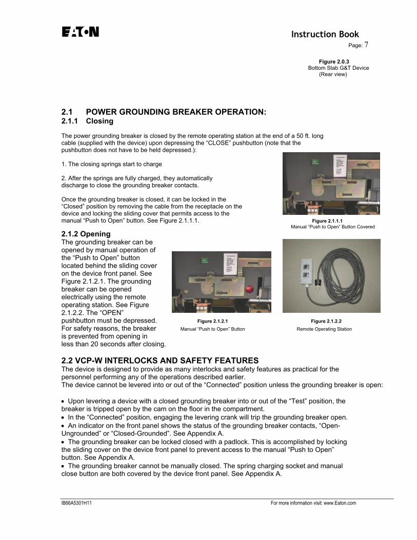
2.1 POWER GROUNDING BREAKER OPERATION: 2.1.1 Closing The power grounding breaker is closed by the remote operating station at the end of a 50 ft. long cable (supplied with the device) upon depressing the “CLOSE” pushbutton (note that the pushbutton does not have to be held depressed.): 1. The closing springs start to charge 2. After the springs are fully charged, they automatically discharge to close the grounding breaker contacts. Once the grounding breaker is closed, it can be locked in the “Closed” position by removing the cable from the receptacle on the device and locking the sliding cover that permits access to the manual “Push to Open” button. See Figure 2.1.1.1. Figure 2.1.1.1 Manual “Push to Open” Button Covered
2.1.2 Opening The grounding breaker can be opened by manual operation of the “Push to Open” button located behind the sliding cover on the device front panel. See Figure 2.1.2.1. The grounding breaker can be opened electrically using the remote operating station. See Figure 2.1.2.2. The “OPEN” pushbutton must be depressed. Figure 2.1.2.1 Figure 2.1.2.2 For safety reasons, the breaker Manual “Push to Open” Button Remote Operating Station is prevented from opening in less than 20 seconds after closing. 2.2 VCP-W INTERLOCKS AND SAFETY FEATURES The device is designed to provide as many interlocks and safety features as practical for the personnel performing any of the operations described earlier. The device cannot be levered into or out of the “Connected” position unless the grounding breaker is open: • Upon levering a device with a closed grounding breaker into or out of the “Test” position, the breaker is tripped open by the cam on the floor in the compartment. • In the “Connected” position, engaging the levering crank will trip the grounding breaker open. • An indicator on the front panel shows the status of the grounding breaker contacts, “Open- Ungrounded” or “Closed-Grounded”. See Appendix A. • The grounding breaker can be locked closed with a padlock. This is accomplished by locking the sliding cover on the device front panel to prevent access to the manual “Push to Open” button. See Appendix A. • The grounding breaker cannot be manually closed. The spring charging socket and manual close button are both covered by the device front panel. See Appendix A.
IB66A5301H11 For more information visit: www.Eaton.com

Instruction Book Page 8 • The grounding breaker can be closed only electrically by a remote operating station at the end of a 50 ft. cable supplied with the device. • The power to operate the grounding breaker in this device is obtained through the secondary disconnect in the breaker compartment. • The grounding breaker cannot be opened electrically in less than 20 seconds after closing. This feature permits the source interrupter to clear a fault if the grounding breaker is inadvertently closed on an energized circuit. See Appendix C. • The control switch cable is connected to the device with a twist lock connector. 2.3 INTERLOCKS - BASIC ELEMENTS DESCRIPTION Key Lock K1 (Keys KU and KB) - The K1 interlock is a two cylinder lock used to electrically enable or disable the G&T Device. In the E.O. G&T Device design, the K1 lock is a two cylinder transfer lock with a switch associated with it. The switch is closed when Key KB is retained. The switch is open and the G&T Device electrically disabled when Key KU is retained. See Figure 2.3.1. Key Lock K2 (Keys KB and KC) - The K2 interlock is a two cylinder lock used to mechanically lock the G&T Device “OPEN”. In the E.O. G&T Device design, the K2 lock function is not needed. It is not possible for an operator of the G&T Device to manually charge the closing springs or to manually close the device to ground. Figure 2.3.1 Figure 2.3.2 See Figure 2.3.2. Key Lock K1 Interlock Key Lock K2 Interlock Key Lock K3 (Key KC) - The K3 interlock is a single cylinder lock, that when locked, prevents the G&T Device from insertion into the breaker compartment. In this design, the K3 lock in the locked position blocks the G&T Device levering latch from engaging the levering nut in the breaker compartment, and an interference hook prevents rolling the breaker in to the cell. In addition, the K3 lock is used to prevent operation of the levering in screw in the Connected position. Operation in the test position is prevented by the interference hook; test operation must be performed out of the cell using the test umbilical cable. Key KC is Figure 2.3.3 removable with the lock bolt extended and the key normally resides in Key Lock K3 Interlock Key Lock K2. See Figure 2.3.3. IB66A5301H11 For more information visit: www.Eaton.com

Instruction Book Page: 9
Key Lock K4 (Keys KB & KD) - The K4 interlock is a two cylinder lock used to mechanically lock the G&T Device in the ”CLOSED -Grounded” position. In this design, the K4 interlock is a two cylinder lock used with the “Closed Locking Device” to prevent the G&T Device from being opened. When the G&T Device is in the “OPEN-Ungrounded” position, the “Closed Locking Device” is disabled. Key KD is retained when the lock bolt is retracted. When the G&T Device is “CLOSED-Grounded”, the “Closed Locking Device” is free to move to the right. The lock bolt can now be extended and the “Closed Locking Device” will be held in the secured “CLOSED-Grounded” position. Key KD is now removable from lock K4. In this secured Figure 2.3.4 position, the “Closed Locking Device” has blocked operator access Key Lock K4 Interlock to the manual “OPEN” pushbutton. Also, in this secured position, an interlock switch electrically disables the electrical “OPEN” function; and a mechanical interlock holds the main contacts in the closed position even if the mechanism is tripped. A padlock hasp is provided for securing the “CLOSED-Grounded” position with a padlock. See Figure 2.3.4. Key Lock K5 (Key KD) - The K5 interlock is a single cylinder lock used to open and lock the test port shutters. In this design, the K5 interlock is a single cylinder lock. Key KD is removable when the lock bolt is extended and the key normally resides in Key Lock K4. Key KD is available only when the G&T Device is locked “CLOSED-Grounded”. Key KD is removable from the K5 interlock in two extended bolt positions. One position is when the Test Port shutters are closed. The second position is when the Figure 2.3.5 Test Probes are inserted in the Test Ports and they are being Key Lock K5 Interlock retained by the “detent” position of the shutter. See Figure 2.3.5. Selector Switch - A selector switch has the “OPEN”, “OFF” and “CLOSE” positions and shall operate in association with the remote “OPEN”/”CLOSE” pushbutton station. See Figure 2.3.6. In this design, the selector switch functions as described below. In the “OFF” position, the G&T Device is electrically disabled. The selector switch is padlockable in the “OFF” position. This provides the padlockable function for the Key Locks K1 and K2. The selector Switch in the “CLOSE” position allows the execution of a remote “CLOSE” command. The “OPEN” function is disabled. Conversely, the selector switch in the “OPEN” position allows the execution of a remote “OPEN” command. The “CLOSE” function is disabled, assuming all other interlocks would permit the operation. Figure 2.3.6
Selector Switch
IB66A5301H11 For more information visit: www.Eaton.com

Instruction Book Page 10 3.0 OPERATION 3.1 SAFE PRACTICES The G&T Device is a safety-related device. It must be recognized that improper use can result in death, serious personal injury, or property damage. That is why it is important that the user develop specific and safe operating procedures for its use.
The following general safe practices are recommended: 1. The device cannot be stored in a VAC CLAD-W breaker compartment. It can only be stored in
its storage compartment.
2. Store the device in a clean, dry area free from dust, dirt, moisture, etc.
3. Keep all insulating surfaces, which include primary support insulation and insulation barriers,
clean and dry.
4. Check all primary circuit connections to make certain that they are clean and tight.
5. Permit only authorized trained personnel to use this device.
6. Take extreme care while using this device to avoid contacting “Live” or “Hot” (energized)
terminals.
7. Do not remove the device front panel while using this device.
8. Always “CLOSE” the grounding breaker electrically from the farthest distance with the remote
control switch.
9. Check for dielectric integrity at 15KV AC across the terminals to ground with the grounding
breaker “OPEN”.
3.2 (RESERVED FOR FUTURE VARIATIONS)
WARNING Improper use can result in death, serious
personal injury, or property damage.
CAUTION The device cannot be stored in VAC CLAD-W breaker
compartment. It can only be stored in its storage compartment.
IB66A5301H11 For more information visit: www.Eaton.com

Instruction Book Page: 11
Typical procedures for use of this G & T Device are as follows: 3.3 APPLYING GROUNDS TO THE POWER CIRCUIT 1. Open the circuit breaker and remove it from its compartment. Refer to circuit breaker instruction manual for instructions on how to install/remove the circuit breaker from its compartment. G & T device is handled in the manner similar to the handling of the circuit breaker. Roll the G&T device (if it is roll-on-the floor type) into the breaker compartment or place it on the extension rails (standard G&T) and push it manually until it latches into test position indicated by crisp metallic sound of the levering latch engagement. An optional dolly available from Eaton can also be used for installation of the G&T device. 2. The Key KU, which is used to start the grounding and testing operations, is obtained from the Lock Box on the premises. 3. Key KU is inserted into Key Lock K1 and is rotated. See Figure 3.3.1. The switch which is associated with Key Lock K1 opens. The G&T Device’s “CLOSE” circuit is electrically disabled. Key KU has electrically locked the G&T Device “OPEN” and is held captive. Key KB is now available in Key Lock K1. 4. Key KB is removed from Key Lock K1 and is inserted into Key Lock K2 and Key KC is rotated. See Figures 3.3.2. and 3.3.3. (The G&T Device is already mechanically locked “OPEN” by virtue of the fact that access to manually charge the closing springs and the manual “CLOSE” button is denied.) Key KB is now held captive in Key Lock K2 and Key KC is now available. Figure 3.3.1 Figure 3.3.2 Figure 3.3.2 Insert Key KU in Key Lock K1 and Remove Key KB from Lock K1 Insert Key KB in Key Lock K2 and
Rotate Rotate Key KC
5. Key KC is removed from Key Lock K2 and is inserted into Key Lock K3 and is rotated. See Figures 3.3.4 and 3.3.5. With the lock bolt retracted, the interlock slider can now be moved to the right releasing the levering latch handle and eliminating the interferences which prevent installation in the cell. See Figure 3.3.6. Figure 3.3.4 Figure 3.3.5 Figure 3.3.6 Remove Key KC from Insert Key KC in Lock K3 Levering Latch Handle is Key Lock K2 and Rotate Released
IB66A5301H11 For more information visit: www.Eaton.com

Instruction Book Page 12 6. Lift the levering latch handle and push the device to the “Test” position as indicated by the crisp clicking sound of the levering latch engaging the levering nut. See Figure 3.3.7. 7. Using the breaker levering crank, lever the G&T Device to the “Connected” position as indicated by the red flag Figure 3.3.7 Figure 3.3.8 appearing in front of and G&T Device Rolled in to G&T Device Levered in to the under the levering crank. Lower Compartment Rails “Connected” Position See Figure 3.3.8. If you have code plate interference, see appendices E, F & G. 8. The K3 interlock is moved back to the left to block the levering latch handle and allow the interference hook to engage the racking mechanism. Note that the latch handle must be pulled forward to allow the blocking plate on the slider to pass over the latch handle. See Figure 3.3.9. Key KC is rotated in Key Lock K3. The levering in screw is made inoperable, locking the G&T Device in the “Connected” position in the breaker. 9. Key KC is removed from Key Lock K3 and is inserted into Key Lock K2 and is rotated. See Figures 3.3.10 and 3.3.11. Key KC is now held captive in Key Lock K2 and Key KB is now available. Figure 3.3.9 Figure 3.3.10 Figure 3.3.11 Levering Device Locked Remove Key KC from Insert Key KC in Key Lock K2 Key Lock K3 and Rotate 10. Remove key KB from Key Lock K2. Insert it into Lock K1. Then rotate key KU. See Figures 3.3.12 and 3.3.13. The G&T Device’s “CLOSE” circuit is electrically enabled. Figure 3.3.12 Figure 3.3.13 Remove Key KB from Insert Key KB in Lock K1 Key Lock K2 and Rotate KU
IB66A5301H11 For more information visit: www.Eaton.com

Instruction Book Page: 13
11. Verify that the three position “OPEN/OFF/CLOSE” Selector Switch on the front of the G&T Device is in the “OFF” position. See Figure 3.3.14. 12. The umbilical cord plug of the Remote Operating Station is inserted into the Figure 3.3.14 Figure 3.3.15 receptacle on the front of the Verify that the Selector Switch is Insert Remote Operating G&T Device. See Figure in the Off Position Station Plug 3.3.15. The Remote Operating Station consists of “OPEN” and “CLOSE” pushbutton switches. 13. The three position “OPEN/ OFF/CLOSE” Selector Switch is then moved from the “OFF” position to the “CLOSE” position. See Figure 3.3.16. Figure 3.3.16 Figure 3.3.17 14. Use the Remote Operating Turn selector switch to Push “Close” Pushbutton Station to “CLOSE” the G&T Close Position Device via the “CLOSE” pushbutton switch from the safest distance. See Figure 3.3.17. 15. Place the “OPEN/OFF/CLOSE” Selector Switch in the “OFF” position. Remove the umbilical cord plug of the Remote Operating Station from the G&T Device. See Figures 3.3.18 and 3.3.19. 16. Key KU is rotated in Key Lock K1 to electrically lock the G&T Device in the “CLOSE” position by electrically disabling the G&T Device’s “OPEN” circuit. Key KB is removed from Key Lock K1 and is locked in the Lock Box on the premises. See Figure 3.3.20. Figure 3.3.18 Figure 3.3.19 Figure 3.3.20 Turn Selector Switch to the Remove Remote Operating Rotate Key KU and Remove Off Position Station Plug Key KB from Key Lock K1
IB66A5301H11 For more information visit: www.Eaton.com
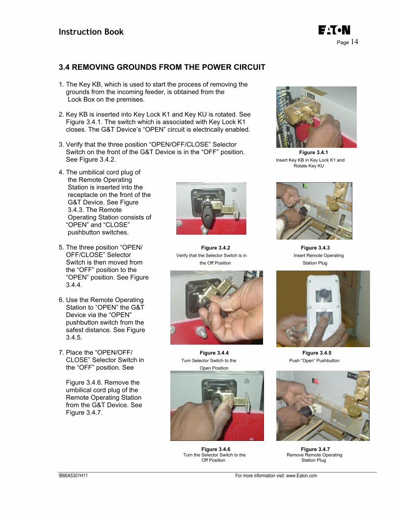
Instruction Book Page 14 3.4 REMOVING GROUNDS FROM THE POWER CIRCUIT 1. The Key KB, which is used to start the process of removing the grounds from the incoming feeder, is obtained from the Lock Box on the premises. 2. Key KB is inserted into Key Lock K1 and Key KU is rotated. See Figure 3.4.1. The switch which is associated with Key Lock K1 closes. The G&T Device’s “OPEN” circuit is electrically enabled. 3. Verify that the three position “OPEN/OFF/CLOSE” Selector Switch on the front of the G&T Device is in the “OFF” position. Figure 3.4.1 See Figure 3.4.2. Insert Key KB in Key Lock K1 and Rotate Key KU 4. The umbilical cord plug of the Remote Operating Station is inserted into the receptacle on the front of the G&T Device. See Figure 3.4.3. The Remote Operating Station consists of “OPEN” and “CLOSE” pushbutton switches. 5. The three position “OPEN/ Figure 3.4.2 Figure 3.4.3 OFF/CLOSE” Selector Verify that the Selector Switch is in Insert Remote Operating Switch is then moved from the Off Position Station Plug the “OFF” position to the “OPEN” position. See Figure 3.4.4. 6. Use the Remote Operating Station to “OPEN” the G&T Device via the “OPEN” pushbutton switch from the safest distance. See Figure 3.4.5. 7. Place the “OPEN/OFF/ Figure 3.4.4 Figure 3.4.5 CLOSE” Selector Switch in Turn Selector Switch to the Push “Open” Pushbutton the “OFF” position. See Open Position Figure 3.4.6. Remove the umbilical cord plug of the Remote Operating Station from the G&T Device. See Figure 3.4.7.
Figure 3.4.6 Figure 3.4.7 Turn the Selector Switch to the Remove Remote Operating Off Position Station Plug
IB66A5301H11 For more information visit: www.Eaton.com

Instruction Book Page: 15
8. Key KU is rotated in Key Lock K1. The switch which is associated with Key Lock K1 opens. The G&T Device’s “CLOSE” circuit is electrically disabled. Key KU has electrically locked the G&T Device “OPEN” and is held captive. Key KB is now available in Key Lock K1. 9. Key KB is removed from Key Lock K1 and is inserted into Key Lock K2 and Key KC is rotated. See Figures 3.4.8 and 3.4.9. (The G&T Device already mechanically locked “OPEN” by virtue of the fact that it is not possible for the operator to manually charge the closings springs and manually “CLOSE” the Figure 3.4.8 Figure 3.4.9 device to ground). Key KB is Rotate Key KU and Remove Insert Key KB in Key Lock K2 and now held captive in Key Lock Key KB from Key Lock K1 Rotate Key KC K2 and KC is now available. 10. Key KC is removed from Key Lock K2 and is inserted into Key Lock K3 and is rotated. See Figures 3.4.10 and 3.4.11. With the lock bolt retracted the interlock can now be moved to the right releasing the levering latch handle and also freeing the levering in screw. See Figure 3.4.12. Figure 3.4.10 Figure 3.4.11 Figure 3.4.12 Remove Key KC from Key Lock K2 Insert Key KC in Key Lock K3 Key KC is Rotated in Key Lock K3 To unlock the levering latch handle And racking screw 11. Using the breaker levering crank, lever the G&T Device out of the “Test” position. See Figure 3.4.13. 12. Align and securely latch the dockable dolly (If applicable) marked “FOR USE WITH G&T DEVICE ONLY” to the extension rails. Figure 3.4.13 G&T Device Levered Into The Test Position
IB66A5301H11 For more information visit: www.Eaton.com

Instruction Book Page 16 13. Disengage the levering latch by lifting the handle on the G&T Device and pulling the G&T Device out of the cell on to its dockable dolly (If applicable.) See Figure 3.4.14. 14. The K3 interlock is moved to the left to engage the levering latch handle. Note that Figure 3.4.15 the latch handle must be Rotate and Remove Key KC From Key Lock K3 pulled forward to allow the blocking plate on the slider to pass above the latch handle. Key KC is rotated in Key Figure 3.4.14 Lock K3. See Figure 3.4.15. Remove G&T Device from Breaker Cell 15. Key KC is removed from Key Lock K3 and is inserted into Key Lock K2 and is rotated. See Figure 3.4.16. Key KC is now held captive in Key Lock K2 and Key KB is now available. 16. Key KB is removed from Key Lock K2 and is inserted into Key Lock K1 and Key KU is rotated. See Figures 3.4.17 and 3.4.18. Figure 3.4.16 The switch which is associated with Key Lock K1 closes. Insert Key KC into Key lock K2 and Rotate 17. Key KU is removed from Key Lock K1 and is locked in the Lock Box on the premises. See Figure 3.4.19. Figure 3.4.17 Figure 3.4.18 Figure 3.4.19
Remove Key KB from Key Lock K2 Insert Key KB in Key Lock K1 and Rotate Key KU Remove Key KU from Key Lock K1
IB66A5301H11 For more information visit: www.Eaton.com

Instruction Book Page: 17
3.5 PROCEDURE FOR INSTALLING TEST PROBES FOR TESTING OF THE POWER CIRCUIT Test Probes may only be installed with the G&T Device installed and closed so that the power circuit line is grounded. To accomplish this, follow the instructions provided in Section 3.3 APPLYING GROUNDS TO THE POWER CIRCUIT. At the completion of the grounding sequence, the Test Probes are installed and the grounding breaker is opened to allow testing using the following procedure: 1. Key KB is removed from Key Lock K1 and is inserted into Key Lock K4. See Figures 3.5.1 and 3.5.2. 2. Since the G&T Device is currently “CLOSED,” the “Closed Locking Device” is free to be moved to the Figure 3.5.1 Figure 3.5.2 right. The hole in the Rotate Key KU and Remove Key KB Insert Key KB in Key Lock K4 “Closed Locking Device” is from Key Lock K1 aligned with the Key Lock K4 bolt opposite it. 3. Key KD is rotated in Key Lock K4 holding the “Closed Locking Device” in the secured “CLOSED” position. See Figure 3.5.3. A position interlock switch, used with the “Closed Locking Device,” has disabled the “OPEN” circuit. Access to the manual “OPEN” pushbutton on the front of he G&T Device has been blocked by the movement of the “Closed Locking Device.” Key KD is now available in Key Lock K4. 4. Key KD is removed from Key Lock K4 and is inserted into Key Figure 3.5.3 Lock K5 and is rotated. See Figures 3.5.4 and 3.5.5. The “Closed Locking Device” Moved to the Right shutter covering the Test Ports is unlocked. Key KD is held and Locked by Rotating Key KD captive when the test ports are allowed to open. See Figure 3.5.6. Figure 3.5.4 Figure 3.5.5 Figure 3.5.6 Remove Key KD from key Lock K4 Insert Key KD in Key Lock K5 and Rotate Open Test Port Shutter
IB66A5301H11 For more information visit: www.Eaton.com

Instruction Book Page 18 5. The Test Probes are inserted into the Test Ports and the shutter is moved all the way to the left. The Test Probes are secured in the Test Ports by the “detent” position of the shutter. See Figure 3.5.7.
Figure 3.5.7 Figure 3.5.8 6. Key KD is rotated in Key Probes Installed and Locked in Place Shutter is Locked with Key Lock K5 Lock K5. The shutter is locked in place. See Figure 3.5.8. Key KD is now available in Key Lock K5. 7. Key KD is removed from Key Lock K5 and is inserted into Key Lock K4 and is rotated. See Figure 3.5.9. The “Closed Locking Device” is released and is spring returned to its left most resting place. The position interlock switch, used with the “Closed Locking Device”, has enabled the “OPEN” circuit. Key KB is now available in Key Lock K4. Figure 3.5.9 Insert Key KD in Key Lock K4 and Rotate 8. Key KB is removed from Key Lock K4 and is inserted into Key Lock K1 and Key Lock KU is rotated. See Figures 3.5.10 and 3.5.11. The switch which is associated with Key Lock K1 closes. The G&T Device’s “OPEN” circuit is electrically enabled. 9. Verify that the three position “OPEN/OFF/ CLOSE” Selector Switch on Figure 3.5.10 Figure 3.5.11 the front of the G&T Device Remove Key KB from key Lock K4 Insert Key KB in Key Lock K1 and Rotate Key KU is in the “OFF” position. See Figure 3.5.12. 10. The umbilical cord plug of the Remote Operating Station is inserted into the receptacle on the front of the G&T Device. See Figure 3.5.13. The Remote Operating Station consists of “OPEN” and “CLOSE” pushbutton switches. Figure 3.5.12 Figure 3.5.13 Verify that the selector Switch is in the Off Position Insert Remote Operating Station Plug
IB66A5301H11 For more information visit: www.Eaton.com

Instruction Book Page: 19
11. The three position “OPEN/OFF/CLOSE” Selector Switch on the front of the G&T Device is moved from the “OFF” to the “OPEN” position. See Figure 3.5.14. 12. Use the Remote Operating Station to “OPEN” the G&T Device via the “OPEN” pushbutton switch from the safest distance. See Figure 3.5.15. 13. Place the “OPEN/OFF/CLOSE” Selector Switch in the “OFF” position. The Remote Operating Station is unplugged from the G&T Device. See Figures 3.5.16 and 3.5.17. Figure 3.5.14 Turn Selector Switch to “Open” Position Figure 3.5.15 Figure 3.5.16 Figure 3.5.17
Push “Open” Pushbutton Turn Selector Switch to “Off” Position Remove Remote Operating Station Plug
14. Key KU is rotated in Key Lock K1. The G&T Device is locked in the “OPEN” position by electrically disabling the G&T Device’s “CLOSE” circuit. Key KB is now available in Key Lock K1. 15. Key KB is removed from Key Lock K1 and is locked in the Lock Box on the premises. See Figure 3.5.18 16. The G&T Device is now available for testing. Figure 3.5.18 Rotate Key KU and Remove Key KB from Key Lock K1
IB66A5301H11 For more information visit: www.Eaton.com

Instruction Book Page 20 3.6 PROCEDURE FOR REMOVING THE TEST PROBES AFTER TESTING This procedure covers removal of the Test Probes at the completion of testing and returning the Power circuit feeder to a grounded condition. 1. The Key KB, which is used to start the process of removing the Test Probes, is obtained from the Lock Box on the premises. 2. Key KB is inserted into Key Lock K1 and Key KU is rotated. See Figure 3.6.1. The switch associated with Key Lock K1 closes. The G&T Device’s “CLOSE” circuit is electrically enabled. 3. Verify that the three position “OPEN/OFF/CLOSE” Selector Switch on the front Figure 3.6.1 Figure 3.6.2 of the G&T Device is in the Insert Key KB in Key Lock K1 and Rotate Key KU Verify that the Selector Switch is in the “ “OFF” position. See Figure OFF” Position 3.6.2. 4. The umbilical cord plug of the Remote Operating Station is inserted into the receptacle on the front of the G&T Device. See Figure 3.6.3. 5. The three position “OPEN/ OFF/CLOSE” Selector Switch is then moved from the “OFF” position to the “CLOSE” Figure 3.6.3 Figure 3.6.4 position. See Figure 3.6.4. Insert the Remote Operating Station Plug Turn the Selector Switch to the “Close” Position 6. Use the Remote Operating Station to “CLOSE” the G&T Device via the “CLOSE” pushbutton switch from the safest distance. See Figure 3.6.5. 7. Place the “OPEN/OFF/CLOSE” Selector Switch in the “OFF” position. See Figure 3.6.6. Remove the umbilical cord plug of the Remote Operating Station from the G&T Device. See Figure 3.6.7. Figure 3.6.5 Figure 3.6.6 Figure 3.6.7
Push “Open” Pushbutton Turn Selector Switch to “Off” Position Remove Remote Operating Station Plug
IB66A5301H11 For more information visit: www.Eaton.com

Instruction Book Page: 21
8. Key KU is rotated in Key Lock K1 to electrically lock the G&T Device in the “CLOSE” position by electrically disabling the G&T Device’s “OPEN” circuit. Key KB is now available in Key Lock K1. 9. Key KB is removed from Key Lock K1 and is inserted into Key Lock K4. See Figures 3.6.8 and 3.6.9. 10. Since the G&T Device is currently “CLOSED,” the “Closed Locking Device” is free to be moved to the right. The hole in the “Closed Locking Device” is aligned Figure 3.6.8 Figure 3.6.9 with the Key Lock K4 bolt Rotate Key KU and Remove Key KB from Key Lock K1 Insert Key KB in Key Lock K4 opposite it. 11. Key KD is rotated in Key Lock K4 holding the “Closed Locking Device” in the secured “CLOSED” position. See Figure 3.6.10. A position interlock switch, used with the “Closed Locking Device,” has electrically disabled the “OPEN” circuit. Access to the manual “OPEN” pushbutton on the front of the G&T Device has been blocked by the movement of the “Closed Locking Device.” Key KD is now available in Key Lock K4. 12. Key KD is removed from Key Lock K4 and is inserted into Key Figure 3.6.10 Lock K5 and is rotated. See “Closed Locking Device” Moved to the Figures 3.6.11 and 3.6.12. Right and Locked by Rotating Key KD The shutter securing the Test Probes in place is unlocked. Key KD is held captive when the Test Ports are open. 13. The Test Probes are removed from the Test Ports. The shutter is moved all the way to the right closing off the Test Ports. Figure 3.6.11 Figure 3.6.12 Remove Key KD from Key Lock K4 Insert Key KD into Key Lock K5 and Remove Probes 14. Key KD is rotated in Key Lock K5 locking the shutter closed. See Figure 3.6.13. Key KD is now available in Key Lock K5. Figure 3.6.13 Close Test Port Shutter and Lock, Remove Key KD
IB66A5301H11 For more information visit: www.Eaton.com

Instruction Book Page 22 15. Key KD is removed from Key Lock K5 and is inserted into Key Lock K4 and is rotated. See Figure 3.6.14. The “Closed Locking Device” is released and is spring returned to it’s leftmost resting place. The position interlock switch, used with the Figure 3.6.14 Figure 3.6.15 “Closed Locking Device,” has Insert Key KD in Key Lock K4 and Rotate Remove Key KB from Key Lock K4 electrically enabled the “OPEN” circuit. Key KB is now available in Key Lock K4. 16. Key KB is removed from Key Lock K4 and is locked in the Lock Box on the premises. See Figures 3.6.15. The power circuit is now grounded with the Test Probes removed. To unground the power Circuit and remove the G&T Device, follow the procedure in Section 3.4 REMOVING GROUNDS FROM THE POWER CIRCUIT.
IB66A5301H11 For more information visit: www.Eaton.com

Instruction Book Page: 23
APPENDIX A - FRONT VIEW
IB66A5301H11 For more information visit: www.Eaton.com

Instruction Book Page 24
NOTES
IB66A5301H11 For more information visit: www.Eaton.com

Instruction Book Page: 25
APPENDIX B – SIDE VIEW (BOTTOM STAB DEVICE)
1. Key Lock K1 (Keys KU and KB) 2. Test Port Padlock (Probes Inserted) 8. Manual Trip Prevent Padlock 14. K3 Levering Screw Interlock 15. Key Lock K3 (KC) 16. Closed Locking Device 17. Closed Locking Device Padlock 18. Key Lock K4 (Keys KB and KD) 20. Selector switch Padlock 21. Selector Switch 22. Key Lock K5 (Key KD) 23. Lever Latch Handle 24. Lower Terminals
IB66A5301H11 For more information visit: www.Eaton.com

Instruction Book Page 26
NOTES
IB66A5301H11 For more information visit: www.Eaton.com

Instruction Book Page: 27
(Standard Scheme – See Note below)
Note: This scheme applies to all Electrical G&T devices except G&T device style numbers 66A5302G83 and 66A5302G93. Refer to Appendix C1 for the schematic for the above listed style numbers.
IB66A5301H11 For more information visit: www.Eaton.com

Instruction Book Page 28
APPENDIX C1 – CONTROL SCHEME (Special Scheme – See Note below)
Note: This scheme applies to G&T devices style numbers 66A5302G83 and 66A5302G93.
WARNING Two Styles of Ground and Test Devices, 66A5302G83 and 66A5302G93, are designed for VCP-WXC
circuit breaker applications only. Potentially severe unintended consequences could result if these devices are misapplied.
IB66A5301H11 For more information visit: www.Eaton.com

Instruction Book Page: 29
IB66A5301H11 For more information visit: www.Eaton.com

Instruction Book Page 30
APPENDIX C2 – VCP-WXC WIRING SCHEMATIC/DIAGRAM
IB66A5301H11 For more information visit: www.Eaton.com
Instruction Book Page: 31
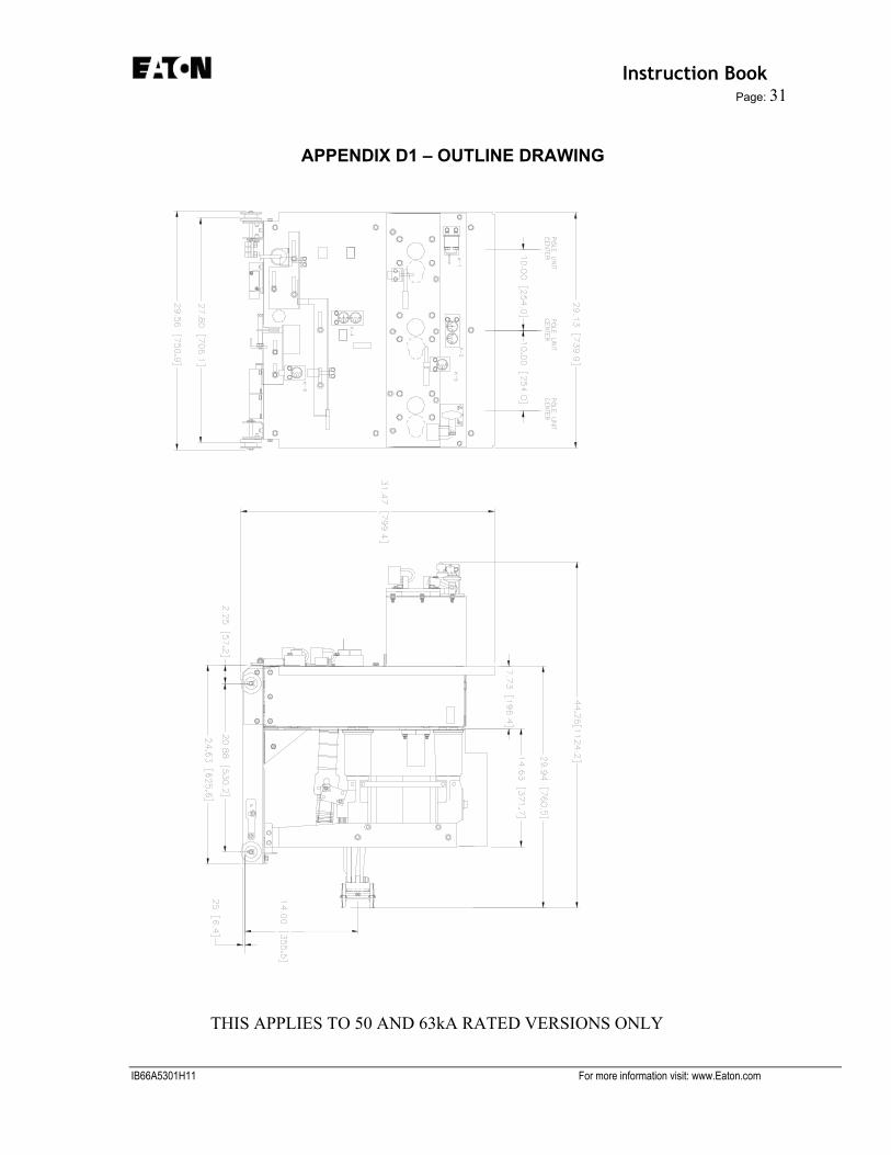
APPENDIX D1 – OUTLINE DRAWING
THIS APPLIES TO 50 AND 63kA RATED VERSIONS ONLY
IB66A5301H11 For more information visit: www.Eaton.com
Instruction Book Page 32
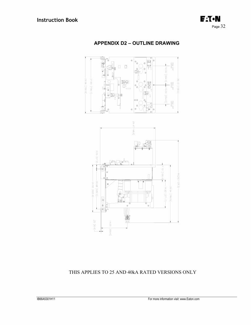
APPENDIX D2 – OUTLINE DRAWING
THIS APPLIES TO 25 AND 40kA RATED VERSIONS ONLY
IB66A5301H11 For more information visit: www.Eaton.com

Instruction Book Page: 33
APPENDIX E – Breaker Code Plate Reference
The chart below shows a summary of the code plates that are on our Eaton breakers. In order to
avoid an interference issue on this particular ground and test device you may need to change the code plates. We apologize for any inconvenience when you encounter code plate interference. The best solution for resolving the interference is to obtain code plates that match the breakers being used. Cross reference this list to find the correct code plates to use. See appendices F & G for information on making code plates.
Breaker Model Current Rating Cycle Class Breaker
LH Code Breaker LH Style Code
Plate Breaker RH Code
Breaker RH Style Code
Plate 150VCP-W 25 1200 3 K=1 12000 8061A47H06 21011 8061A40H07 150VCP-W 25 1200 5 K=1 12000 8061A47H06 21012 8061A41H01 150VCP-W 25 2000 3 K=1 11000 8061A38H06 21011 8061A40H07 150VCP-W 25 2000 5 K=1 11000 8061A38H06 21012 8061A41H01 150VCP-W 25 3000 3 K=1 20000 8061A40H06 21011 8061A40H07 150VCP-W 25 3000 5 K=1 20000 8061A40H06 21012 8061A41H01
150VCP-W 25 C 1200 C C 21010 8061A38H01 21102 8061A44H02 150VCP-W 25 C 2000 C C 21010 8061A38H01 21101 8061A48H03 150VCP-W 25 C 3000 C C 21010 8061A38H01 21110 8061A38H03 150VCP-W 40 1200 3 K=1 12000 8061A47H06 11011 8061A38H05 150VCP-W 40 1200 5 K=1 12000 8061A47H06 11012 8061A38H04 150VCP-W 40 2000 3 K=1 11000 8061A38H06 11011 8061A38H05 150VCP-W 40 2000 5 K=1 11000 8061A38H06 11012 8061A38H04 150VCP-W 40 3000 3 K=1 20000 8061A40H06 11011 8061A38H05 150VCP-W 40 3000 5 K=1 20000 8061A40H06 11012 8061A38H04
150VCP-W 40 C 1200 C C 00010 8061A39H04 10102 8061A46H02 150VCP-W 40 C 2000 C C 00010 8061A39H04 10101 8061A50H02 150VCP-W 40 C 3000 C C 00010 8061A39H04 10110 8061A39H05 150VCP-W 50 1200 3 K=1 12000 8061A47H06 10011 8061A40H02 150VCP-W 50 1200 5 K=1 12000 8061A47H06 10012 8061A42H01 150VCP-W 50 2000 3 K=1 11000 8061A38H06 10011 8061A40H02 150VCP-W 50 2000 5 K=1 11000 8061A38H06 10012 8061A42H01 150VCP-W 50 3000 3 K=1 20000 8061A40H06 10011 8061A40H02 150VCP-W 50 3000 5 K=1 20000 8061A40H06 10012 8061A42H01
150VCP-W 50 C 1200 C C 00010 8061A39H04 00102 8061A39H06 150VCP-W 50 C 2000 C C 00010 8061A39H04 00101 8061A39H07 150VCP-W 50 C 3000 C C 00010 8061A39H04 00110 8061A39H08 150VCP-W 63 1200 3 K=1 10010 8061A39H01 00002 8061A39H02 150VCP-W 63 1200 3 K=1 10010 8061A39H01 00002 8061A39H02 150VCP-W 63 1200 5 K=1 10020 8061A33H01 00002 8061A39H02 150VCP-W 63 1200 5 K=1 10020 8061A33H01 00002 8061A39H02 150VCP-W 63 2000 3 K=1 10010 8061A39H01 00001 8061A39H03
IB66A5301H11 For more information visit: www.Eaton.com

Instruction Book Page 34
150VCP-W 63 2000 3 K=1 10010 8061A39H01 00001 8061A39H03 150VCP-W 63 2000 5 K=1 10020 8061A33H01 00001 8061A39H03 150VCP-W 63 2000 5 K=1 10020 8061A33H01 00001 8061A39H03 150VCP-W 63 3000 3 K=1 10010 8061A39H01 00010 8061A39H04 150VCP-W 63 3000 3 K=1 10010 8061A39H01 00010 8061A39H04 150VCP-W 63 3000 5 K=1 10020 8061A33H01 00010 8061A39H04 150VCP-W 63 3000 5 K=1 10020 8061A33H01 00010 8061A39H04
150VCP-W 63 C 1200 C C 10000 8061A50H03 00002 8061A39H02 150VCP-W 63 C 2000 C C 10000 8061A50H03 00001 8061A39H03 150VCP-W 63 C 3000 C C 10000 8061A50H03 00010 8061A39H04 150VCP-W1000 1200 3 K>1 10010 8061A39H01 10002 8061A46H01 150VCP-W1000 1200 5 K>1 10020 8061A33H01 10002 8061A46H01 150VCP-W1000 2000 3 K>1 10010 8061A39H01 10001 8061A50H01 150VCP-W1000 2000 5 K>1 10020 8061A33H01 10001 8061A50H01 150VCP-W1000 3000 3 K>1 10010 8061A39H01 10010 8061A39H01 150VCP-W1000 3000 5 K>1 10020 8061A33H01 10010 8061A39H01 150VCP-W500 1200 3 K>1 22010 8061A37H01 22002 8061A43H01 150VCP-W500 1200 5 K>1 22020 8061A31H01 22002 8061A43H01 150VCP-W500 2000 3 K>1 22010 8061A37H01 22001 8061A47H01 150VCP-W500 2000 5 K>1 22020 8061A31H01 22001 8061A47H01 150VCP-W500 3000 3 K>1 22010 8061A37H01 22010 8061A37H01 150VCP-W500 3000 5 K>1 22020 8061A31H01 22010 8061A37H01
150VCP-W500 H 1200 3 K>1 22010 8061A37H01 21002 8061A44H01 150VCP-W500 H 1200 5 K>1 22020 8061A31H01 21002 8061A44H01 150VCP-W500 H 2000 3 K>1 22010 8061A37H01 21001 8061A48H01 150VCP-W500 H 2000 5 K>1 22020 8061A31H01 21001 8061A48H01 150VCP-W500 H 3000 3 K>1 22010 8061A37H01 21010 8061A38H01 150VCP-W500 H 3000 5 K>1 22020 8061A31H01 21010 8061A38H01 150VCP-W750 1200 3 K>1 21010 8061A38H01 21002 8061A44H01 150VCP-W750 1200 5 K>1 21020 8061A32H01 21002 8061A44H01 150VCP-W750 2000 3 K>1 21010 8061A38H01 21001 8061A48H01 150VCP-W750 2000 5 K>1 21020 8061A32H01 21001 8061A48H01 150VCP-W750 3000 3 K>1 21010 8061A38H01 21010 8061A38H01 150VCP-W750 3000 5 K>1 21020 8061A32H01 21010 8061A38H01
150VCP-W750 H 1200 3 K>1 21010 8061A38H01 10002 8061A46H01 150VCP-W750 H 1200 5 K>1 21020 8061A32H01 10002 8061A46H01 150VCP-W750 H 2000 3 K>1 21010 8061A38H01 10001 8061A50H01 150VCP-W750 H 2000 5 K>1 21020 8061A32H01 10001 8061A50H01 150VCP-W750 H 3000 3 K>1 21010 8061A38H01 10010 8061A39H01 150VCP-W750 H 3000 5 K>1 21020 8061A32H01 10010 8061A39H01
IB66A5301H11 For more information visit: www.Eaton.com

Instruction Book Page: 35
150VCP-WG 50 1200 3 K=1 10020 8061A33H01 00002 8061A39H02 150VCP-WG 50 2000 3 K=1 10020 8061A33H01 00001 8061A39H03 150VCP-WG 50 3000 3 K=1 10020 8061A33H01 00010 8061A39H04 150VCP-WG 63 1200 3 K=1 10020 8061A33H01 00002 8061A39H02 150VCP-WG 63 2000 3 K=1 10020 8061A33H01 00001 8061A39H03 150VCP-WG 63 3000 3 K=1 10020 8061A33H01 00010 8061A39H04
50VCP-W 25 1200 3 K=1 12002 8061A47H05 21011 8061A40H07 50VCP-W 25 1200 5 K=1 12002 8061A47H05 21012 8061A41H01 50VCP-W 25 2000 3 K=1 11002 3A74923H01 21011 8061A40H07 50VCP-W 25 2000 5 K=1 11002 3A74923H01 21012 8061A41H01 50VCP-W 25 3000 3 K=1 20002 8061A45H01 21011 8061A40H07 50VCP-W 25 3000 5 K=1 20002 8061A45H01 21012 8061A41H01
50VCP-W 25 C 1200 C C 21012 8061A41H01 21102 8061A44H02 50VCP-W 25 C 2000 C C 21012 8061A41H01 21101 8061A48H03 50VCP-W 25 C 3000 C C 21012 8061A41H01 21110 8061A38H03 50VCP-W 40 1200 3 K=1 12002 8061A47H05 11011 8061A38H05 50VCP-W 40 1200 5 K=1 12002 8061A47H05 11012 8061A38H04 50VCP-W 40 2000 3 K=1 11002 3A74923H01 11011 8061A38H05 50VCP-W 40 2000 5 K=1 11002 3A74923H01 11012 8061A38H04 50VCP-W 40 3000 3 K=1 20002 8061A45H01 11011 8061A38H05 50VCP-W 40 3000 5 K=1 20002 8061A45H01 11012 8061A38H04
50VCP-W 40 C 1200 C C 00012 8061A42H02 10102 8061A46H02 50VCP-W 40 C 2000 C C 00012 8061A42H02 10101 8061A50H02 50VCP-W 40 C 3000 C C 00012 8061A42H02 10110 8061A39H05 50VCP-W 50 1200 3 K=1 12002 8061A47H05 10011 8061A40H02 50VCP-W 50 1200 5 K=1 12002 8061A47H05 10012 8061A42H01 50VCP-W 50 2000 3 K=1 11002 3A74923H01 10011 8061A40H02 50VCP-W 50 2000 5 K=1 11002 3A74923H01 10012 8061A42H01 50VCP-W 50 3000 3 K=1 20002 8061A45H01 10011 8061A40H02 50VCP-W 50 3000 5 K=1 20002 8061A45H01 10012 8061A42H01
50VCP-W 50 C 1200 C C 00012 8061A42H02 00102 8061A39H06 50VCP-W 50 C 2000 C C 00012 8061A42H02 00101 8061A39H07 50VCP-W 50 C 3000 C C 00012 8061A42H02 00110 8061A39H08 50VCP-W 63 1200 3 K=1 10012 8061A42H01 00002 8061A39H02 50VCP-W 63 1200 3 K=1 10012 8061A42H01 00002 8061A39H02 50VCP-W 63 1200 5 K=1 10022 8061A36H01 00002 8061A39H02 50VCP-W 63 1200 5 K=1 10022 8061A36H01 00002 8061A39H02 50VCP-W 63 2000 3 K=1 10012 8061A42H01 00001 8061A39H03 50VCP-W 63 2000 3 K=1 10012 8061A42H01 00001 8061A39H03 50VCP-W 63 2000 5 K=1 10022 8061A36H01 00001 8061A39H03
IB66A5301H11 For more information visit: www.Eaton.com

Instruction Book Page 36
50VCP-W 63 2000 5 K=1 10022 8061A36H01 00001 8061A39H03 50VCP-W 63 3000 3 K=1 10012 8061A42H01 00010 8061A39H04 50VCP-W 63 3000 3 K=1 10012 8061A42H01 00010 8061A39H04 50VCP-W 63 3000 5 K=1 10022 8061A36H01 00010 8061A39H04 50VCP-W 63 3000 5 K=1 10022 8061A36H01 00010 8061A39H04
50VCP-W 63 C 1200 C C 00012 8061A42H02 00002 8061A39H02 50VCP-W 63 C 2000 C C 00012 8061A42H02 00001 8061A39H01 50VCP-W 63 C 3000 C C 00012 8061A42H02 00010 8061A39H04 50VCP-W ND
250 1200 3 K>1 21212 8061A61H01 None None
50VCP-W ND 250 1200 5 K>1 21222 8061A60H01 None None
50VCP-W250 1200 3 K>1 21012 8061A41H01 21002 8061A44H01 50VCP-W250 1200 5 K>1 21022 8061A35H01 21002 8061A44H01 50VCP-W250 2000 3 K>1 21012 8061A41H01 21001 8061A48H01 50VCP-W250 2000 5 K>1 21022 8061A35H01 21001 8061A48H01 50VCP-W250 3000 3 K>1 21012 8061A41H01 21010 8061A38H01 50VCP-W250 3000 5 K>1 21022 8061A35H01 21010 8061A38H01
50VCP-W250 H 1200 3 K>1 21012 8061A41H01 10002 8061A46H01 50VCP-W250 H 1200 5 K>1 21022 8061A35H01 10002 8061A46H01 50VCP-W250 H 2000 3 K>1 21012 8061A41H01 10001 8061A50H01 50VCP-W250 H 2000 5 K>1 21022 8061A35H01 10001 8061A50H01 50VCP-W250 H 3000 3 K>1 21012 8061A41H01 10010 8061A39H01 50VCP-W250 H 3000 5 K>1 21022 8061A35H01 10010 8061A39H01 50VCP-W350 1200 3 K>1 10012 8061A42H01 10002 8061A46H01 50VCP-W350 1200 5 K>1 10022 8061A36H01 10002 8061A46H01 50VCP-W350 2000 3 K>1 10012 8061A42H01 10001 8061A50H01 50VCP-W350 2000 5 K>1 10022 8061A36H01 10001 8061A50H01 50VCP-W350 3000 3 K>1 10012 8061A42H01 10010 8061A39H01 50VCP-W350 3000 5 K>1 10022 8061A36H01 10010 8061A39H01 50VCP-WG 50 1200 3 K=1 10022 8061A36H01 00002 8061A39H02 50VCP-WG 50 2000 3 K=1 10022 8061A36H01 00001 8061A39H03 50VCP-WG 50 3000 3 K=1 10022 8061A36H01 00010 8061A39H04 50VCP-WG 63 1200 3 K=1 10022 8061A36H01 00002 8061A39H02 50VCP-WG 63 2000 3 K=1 10022 8061A36H01 00001 8061A39H03 50VCP-WG 63 3000 3 K=1 10022 8061A36H01 00010 8061A39H04 75VCP-W 40 1200 3 K=1 12001 8061A47H02 11011 8061A38H05 75VCP-W 40 1200 5 K=1 12001 8061A47H02 11012 8061A38H04 75VCP-W 40 2000 3 K=1 11001 8061A48H02 11011 8061A38H05 75VCP-W 40 2000 5 K=1 11001 8061A48H02 11012 8061A38H04 75VCP-W 40 3000 3 K=1 20001 8061A49H01 11011 8061A38H05
IB66A5301H11 For more information visit: www.Eaton.com

Instruction Book Page: 37
75VCP-W 40 3000 5 K=1 20001 8061A49H01 11012 8061A38H04 75VCP-W 50 1200 3 K=1 12001 8061A47H02 10011 8061A40H02 75VCP-W 50 1200 5 K=1 12001 8061A47H02 10012 8061A42H01 75VCP-W 50 2000 3 K=1 11001 8061A48H02 10011 8061A40H02 75VCP-W 50 2000 5 K=1 11001 8061A48H02 10012 8061A42H01 75VCP-W 50 3000 3 K=1 20001 8061A49H01 10011 8061A40H02 75VCP-W 50 3000 5 K=1 20001 8061A49H01 10012 8061A42H01
75VCP-W 50 C 1200 C C 10011 8061A40H02 00102 8061A46H02 75VCP-W 50 C 2000 C C 10011 8061A40H02 00101 8061A50H02 75VCP-W 50 C 3000 C C 10011 8061A40H02 00110 8061A39H05 75VCP-W500 1200 3 K>1 20011 8061A40H01 20002 8061A45H01 75VCP-W500 1200 5 K>1 20021 8061A34H01 20002 8061A45H01 75VCP-W500 2000 3 K>1 20011 8061A40H01 20001 8061A49H01 75VCP-W500 2000 5 K>1 20021 8061A34H01 20001 8061A49H01 75VCP-W500 3000 3 K>1 20011 8061A40H01 20010 8061A51H01 75VCP-W500 3000 5 K>1 20021 8061A34H01 20010 8061A51H01
IB66A5301H11 For more information visit: www.Eaton.com

Instruction Book Page 38
APPENDIX F – How To Make Breaker Plates
IB66A5301H11 For more information visit: www.Eaton.com

Instruction Book Page: 39
APPENDIX G – How To Make Cell Plates
IB66A5301H11 For more information visit: www.Eaton.com

Instruction Book Page 40
IB66A5301H11 For more information visit: www.Eaton.com

Instruction Book Page: 41
IB66A5301H11 For more information visit: www.Eaton.com

Instruction Book Page 42
IB66A5301H11 For more information visit: www.Eaton.com

Instruction Book Page: 43
IB66A5301H11 For more information visit: www.Eaton.com

Instruction Book Page 44
IB66A5301H11 For more information visit: www.Eaton.com

Instruction Book Page: 45
IB66A5301H11 For more information visit: www.Eaton.com

Instruction Book Page 46
NOTES
IB66A5301H11 For more information visit: www.Eaton.com
Instruction Book Page: 47
__________________________________________________________________
This instruction booklet is published solely for information purpose and should not be considered all inclusive. If further information is required, you should consult Electric Services Inc. NO WARRANTIES, EXPRESSED OR IMPLIED. INCLUDING WARRANTIES OF FITNESS FOR A PARTICULAR PURPOSE OR MERCHANTABILITY, OR WARRANTIES ARISING FROM COURSE OF DEALING OR USAGE OF TRADE, ARE MADE REGARDING THE INFORMATION, RECOMMENDATIONS AND DESCRIPTIONS CONTAINED HEREIN. In no event will Electric Services Inc. be responsible to the purchaser or user in contract, (including negligence), strict liability or otherwise for any special, indirect, incidental or consequential damage or loss of whatsoever, including but not limited to damage or loss of use of equipment, plant or power system, cost of capital, loss of power, additional expenses in the use of existing power facilities, or claims against the purchaser or user by its customers resulting from the use of the information, recommendations and descriptions contained herein.
_____________________________________________________________________
IB66A5301H11 For more information visit: www.Eaton.com