· tripura industrial development corporation invitation for bid 2 july 2018 contents book-1...
TRANSCRIPT

TRIPURA INDUSTRIAL DEVELOPMENT CORPORATION
Tender for Setting up of Land Custom Station, Muhurighat,Belonia,
TIDC/LCS/CIVIL/MUHURIGHAT/01/2018
General Condition of Contract
Project Management Consultants:
TRIPURA INDUSTRIAL DEVELOPMENT CORPORATION
Tender for Setting up of Land Custom Station, Muhurighat,Belonia,
Tripura
TIDC/LCS/CIVIL/MUHURIGHAT/01/2018-19
BOOK – 1
General Condition of Contract
Consultants: - JULY
TRIPURA INDUSTRIAL DEVELOPMENT CORPORATION
Tender for Setting up of Land Custom Station, Muhurighat,Belonia,
19
JULY 2018
http://tripurainfo.com/Tenders.aspx

TRIPURA INDUSTRIAL DEVELOPMENT CORPORATION
Tender for Setting up of Land Custom Station at Muhurighat, Belonia,
Tripura
Serial No……………………………
Date of Issue …………………………..
Tender Document issued to:
M/s ……………………………………………………
…………………………………………………….
…………………………………………………….
By
Managing Director
Tripura Industrial Development Corporation (TIDC)
Shilpanigam Bhavan,
Khejurbagan,
P.O Kunjaban, Agartala,
Tripura - 799006
http://tripurainfo.com/Tenders.aspx
Tripura Industrial Development Corporation INVITATION FOR BID
2 July 2018
CONTENTS
BOOK-1 INVITATION FOR BID
Section-1 Instruction to Bidders
1A General Instructions
1B Bidding Documents
1C Preparation of bids
1D Submission of Bids
1E Bid Opening and Evaluation
Section-2 Forms of Bid
Qualification Information
Format for Evidence of Access to or Availability of Credit Facilities,
Letter of Acceptance
Issue of Notice to proceed with the work
Agreement Form
Section-3 Conditions of Contract
3A General Conditions
3B Time Control
3C Quality Control
3D Cost Control
3E Finishing the Contract
3F Special Conditions of Contract
Section-4 Contract Data
Section-5 Forms of Securities
Bid Security
Performance Bank Guarantee
Performance Bank Guarantee for Unbalanced Items and Bank
Guarantee for Advance Payment
http://tripurainfo.com/Tenders.aspx
Tripura Industrial Development Corporation INVITATION FOR BID
3 July 2018
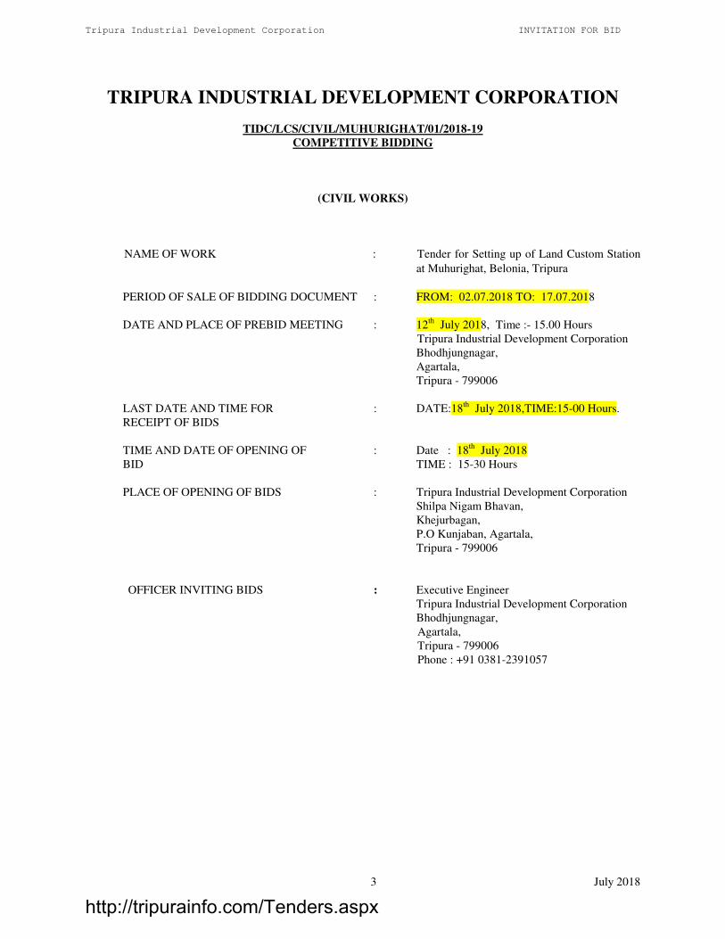
TRIPURA INDUSTRIAL DEVELOPMENT CORPORATION
TIDC/LCS/CIVIL/MUHURIGHAT/01/2018-19
COMPETITIVE BIDDING
(CIVIL WORKS)
NAME OF WORK : Tender for Setting up of Land Custom Station
at Muhurighat, Belonia, Tripura
PERIOD OF SALE OF BIDDING DOCUMENT : FROM: 02.07.2018 TO: 17.07.2018
DATE AND PLACE OF PREBID MEETING : 12th
July 2018, Time :- 15.00 Hours
Tripura Industrial Development Corporation
Bhodhjungnagar,
Agartala,
Tripura - 799006
LAST DATE AND TIME FOR : DATE:18th
July 2018,TIME:15-00 Hours.
RECEIPT OF BIDS
TIME AND DATE OF OPENING OF : Date : 18th
July 2018
BID TIME : 15-30 Hours
PLACE OF OPENING OF BIDS : Tripura Industrial Development Corporation
Shilpa Nigam Bhavan,
Khejurbagan,
P.O Kunjaban, Agartala,
Tripura - 799006
OFFICER INVITING BIDS : Executive Engineer
Tripura Industrial Development Corporation
Bhodhjungnagar,
Agartala,
Tripura - 799006
Phone : +91 0381-2391057
http://tripurainfo.com/Tenders.aspx

Tripura Industrial Development Corporation INVITATION FOR BID
4 July 2018
INVITATION FOR BID
(IFB)
http://tripurainfo.com/Tenders.aspx

Tripura Industrial Development Corporation INVITATION FOR BID
July 2018 5
TRIPURA INDUSTRIAL DEVELOPMENT CORPORATION
INVITATIONS FOR BIDS (IFB)
COMPETITIVE BIDDING
Date: 02.07.2018
Bid No: TIDC/LCS/CIVIL/MUHURIGHAT/01/2018-19
1. Tripura Industrial Development Corporation (TIDC), Agartala is promoting Setting Up of Land
Custom Station at Muhurighat, Belonia, Tripura, under the ASIDE scheme of the Government of India
and invites percentage rate bids for the below mentioned works from the eligible bidders registered
with the Governments/Semi Government organisations.
2 Sale of tender documents shall commence from 2nd
July 2018. The intending Contractors shall have the
documents from the below mentioned addresses on payment of cost thereof in the form of Demand
Draft on any Scheduled bank payable at Agartala in favour of Tripura Industrial Development
Corporation till 15.00 hrs on 17th
July 2018 and request quoting the reference number
TIDC/LCS/CIVIL/MUHURIGHAT/01/2018-19. Interested bidders may obtain further information at
the same addresses. Bidding documents requested by mail will be despatched by registered/speed post
on payment of an extra amount of Rs 500/-. Tripura Industrial Development Corporation, will not be
held responsible for the postal delay if any, in the delivery of the documents or non-receipt of the same.
Executive Engineer,
Tripura Industrial Development Corporation
Bhodhjungnagar, Agartala,
Tripura - 799006
Phone : +91 0381-2391057
IL&FS, Cluster Development Initiative Ltd,
Dasgupta Villa,
1st Floor, North Side of Governor’s house,
Vill & PO-Kunjaban, Agartala – 799006
Phone: +91 0381-2300419
3. Bids must be accompanied by bid security of the amount specified for the work in the table IFB 1,
drawn in favour of Tripura Industrial Development Corporation. Bid security will have to be in any one
of the forms as specified in the bidding document and shall have to be valid for 90 days beyond the
validity of the bid.
4. A pre-bid meeting will be held on 12th
July 2018 at TIDC office at 15.00 Hours to clarify the issues, if
any.
5. Bids must be delivered to Office of the Managing Director, Tripura Industrial Development
Corporation, Shilpa Nigam Bhavan, Khejurbagan, P.O Kunjaban, Agartala, Tripura – 799006 on or
before 15-00 Hours on 18th July 2018 and will be opened on the same day at 15-30 hours, in the
presence of the bidders who wish to attend. If the office happens to be closed on the date of receipt of
the bids as specified, the bids will be received and opened on the next working day at the same time and
venue.
6. Other details can be seen in the bidding documents.
http://tripurainfo.com/Tenders.aspx

Tripura Industrial Development Corporation INVITATION FOR BID
July 2018 6
TABLE - IFB 1
Package
No.
Name of work Estimated
Value of
work
(Rs.in Lakhs)
Bid security /
EMD
(Rs.in
Lakhs)
Cost of
document
(Rs.)
Period of
completion
1 Setting Up of Land Custom Station
at Muhurighat, Belonia, Tripura
1140.78 11.40 5,000 24 Months
Seal of office
http://tripurainfo.com/Tenders.aspx

Tripura Industrial Development Corporation INVITATION FOR BID
July 2018 7
SECTION 1: INSTRUCTIONS TO BIDDERS
(ITB)
http://tripurainfo.com/Tenders.aspx
Tripura Industrial Development Corporation INVITATION FOR BID
July 2018 8
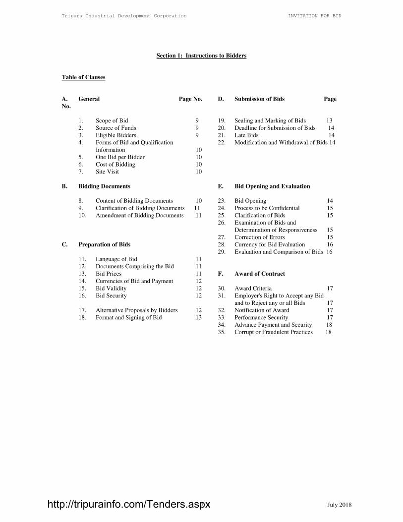
Section 1: Instructions to Bidders
Table of Clauses
A. General Page No. D. Submission of Bids Page
No.
1. Scope of Bid 9 19. Sealing and Marking of Bids 13
2. Source of Funds 9 20. Deadline for Submission of Bids 14
3. Eligible Bidders 9 21. Late Bids 14
4. Forms of Bid and Qualification 22. Modification and Withdrawal of Bids 14
Information 10
5. One Bid per Bidder 10
6. Cost of Bidding 10
7. Site Visit 10
B. Bidding Documents E. Bid Opening and Evaluation
8. Content of Bidding Documents 10 23. Bid Opening 14
9. Clarification of Bidding Documents 11 24. Process to be Confidential 15
10. Amendment of Bidding Documents 11 25. Clarification of Bids 15
26. Examination of Bids and
Determination of Responsiveness 15
27. Correction of Errors 15
C. Preparation of Bids 28. Currency for Bid Evaluation 16
29. Evaluation and Comparison of Bids 16
11. Language of Bid 11
12. Documents Comprising the Bid 11
13. Bid Prices 11 F. Award of Contract
14. Currencies of Bid and Payment 12
15. Bid Validity 12 30. Award Criteria 17
16. Bid Security 12 31. Employer's Right to Accept any Bid
and to Reject any or all Bids 17
17. Alternative Proposals by Bidders 12 32. Notification of Award 17
18. Format and Signing of Bid 13 33. Performance Security 17
34. Advance Payment and Security 18
35. Corrupt or Fraudulent Practices 18
http://tripurainfo.com/Tenders.aspx

Tripura Industrial Development Corporation INVITATION FOR BID
July 2018 9
A. General
1. Scope of Bid
1.1 Tripura Industrial Development Corporation, (referred to as Employer in these documents) invite bids
for the construction of works (as defined in these documents and referred to as "the Works") detailed in
the table No.IFB-1.
1.2 This is a single stage Tender ( 2 Envelopes System).
1.3 The successful bidder will be expected to complete the works within a period of Twenty Four months
including rainy season..
2. Source of Funds
2.1 The Works in this contract shall be funded by Tripura Industrial Development Corporation and
Government Of India.
3. Eligible Bidders
3.1 Bidder’s Qualification criteria
• The Applicant shall have been involved in the Civil Engineering Construction Business such as
building works, road works and water supply distribution works for the last ten years or more. The
Applicant must provide necessary supporting documents as proof in respect of the eligibility criteria
mentioned below:
• Experience of having successfully completed one similar work costing not less Rs. 11.40 Crores in a
single tender in 24 months in last 7 years
Completion report duly certified by the employer is to be submitted.
• Similar work shall mean “Development and Construction of multi-storied Office Buildings/Commercial
complex with RCC framed structure, large span steel structure, including Internal and external
Electrical works, renewable energy, recycled water management systems, radiant cooling, firefighting
works, security systems, interior works”
• The Bidder should also have completed at least one single contract if similar nature, i.e Building works
and allied civil works including electrical works in the state of Tripura of value not less than Rs. 9.12
crores (80% of estimated value of works) and should also submit documentary evidence duly
certified by client.
• The Bidder should also have completed at least one single contract of Road work of value not less than
Rs. 2 crores in the state of Tripura/outside Tripura & should also submit documentary evidence duly
certified by client
• Average Annual Financial Turnover during last 3 years ending 31st March 2018, should be at
least 11.40 Crores. (Please submit copies of audited balance sheets of last 3 years i.e. from 2015-
16, 2016-17 and 2017-18)
• Shall have a solvency of Rs.4.56 Crores (40% of the estimated value of works). The applicant shall
submit the solvency certificate, not older than three months prior to 31st March 2018, issued by any
scheduled bank in original.
• The Bidder should have Permanent A.C. (PAN) with income tax department.
http://tripurainfo.com/Tenders.aspx

Tripura Industrial Development Corporation INVITATION FOR BID
July 2018 10
• The Bidder should have P.F & ESI registration with the concerned departments.
• The bidder must possess of his own or hire necessary plant and equipments viz. i) Concrete Batching
Plant 18m³/hour capacity, concrete pump 20 m³/h capacity, ii) 100 to 120 TPH Batch Type Hot Mix
Plant, iii)Vibro Roller, iv) paver finisher and all tool & tackles, instrument etc required for successful
execution of the job. For hire. Agreement/lease documents of all the plants and documents should be
furnished along with the consent letter from the respected parties for at least 3 to 7 months.
• Shall not be black listed by any State/Central Department or PSU or Autonomous bodies.
The Applicant must submit a duly notarized Affidavit to this effect. Bids received without this
declaration in original shall stand automatically rejected.
• The applicant must submit information of on-going litigations and litigations had in the past five years.
In the event that the applicant has no litigations either in process or in the past 5 years, an Affidavit to
this effect, duly notarized must be submitted in original.
• Joint Venture or Consortiums are not allowed to quote for this tender.
• All certificates/Documents mentioned above must be notarized before submission
4. Forms of Bid and Qualification Information
All bidders shall fill in Section 2, Forms of Bid and Qualification Information”, and also submit a
statement that the Bidder is not associated, nor has been associated in the past, directly or indirectly,
with the Construction Manager, Engineer or any other entity that has prepared the design,
specifications, and other documents for the Project or being proposed as Project Manager for the
Contract.
5. One Bid per Bidder
5.1 Each bidder shall submit only one bid for one contract. A bidder who submits or participates in more
than one Bid (other than as a Sub-contractor or in cases of alternatives that have been permitted or
requested) will cause all the proposals with the Bidder’s participation to be disqualified.
5.2 Tender documents are not transferable
6. Cost of Bidding
6.1 The bidder shall bear all costs associated with the preparation and submission of his Bid, and the
Employer will in no case be responsible and liable for those costs.
7. Site visit
7.1 The Bidder, at the Bidder’s own responsibility and risk is encouraged to visit and examine the Site of
Works and its surroundings and obtain all information that may be necessary for preparing the Bid and
entering into a contract for construction of the Works. The costs of visiting the Site shall be at the
Bidder's own expense.
B. Bidding Documents
8. Contents of Bidding Documents
8.1 The set of bidding documents comprises the documents listed in the table below and addenda issued in
accordance with Clause 10:
http://tripurainfo.com/Tenders.aspx

Tripura Industrial Development Corporation INVITATION FOR BID
July 2018 11
Book 1 Invitation for Bids containing Sections as below.
Sections 1 Instructions to Bidders
2 Forms of Bid and Qualification Information
3 Conditions of Contract
4 Contract Data
5 Forms of Securities
Book-2 Specifications
Book-3 Bill of Quantities
8.2 Only one set of original bidding document will be provided. The original document prepared for
submission have to be photocopied by the Bidder, for submission together with the Original.
9. Clarification of Bidding Documents
9.1 A prospective bidder requiring any clarification of the bidding documents may notify the Employer in
writing or by fax at the Employer's address indicated in the invitation to bid on or before the prebid
meeting date. The Employer will respond to any request for clarification which he receives. Copies of
the Employer's response will be forwarded to all purchasers of the bidding documents, including a
description of the enquiry but without identifying its source.
9.2 Pre-bid Meeting
9.2.1 The bidder or his official representative having authorization to attend, is invited to attend a pre-bid
meeting which will take place at Tripura Industrial Development Corporation, Agartala on 12th
July
2018 at 15.00 Hours. The purpose of meeting will be to clarify issues if any.
10. Amendment of Bidding Documents
10.1 Before the deadline for submission of bids, the Employer may modify the bidding documents by issuing
tender addenda.
10.2 Any addendum thus issued shall be part of the bidding documents and shall be communicated in writing
or by fax to all the purchasers of the bidding documents. Prospective bidders shall acknowledge receipt
of each addendum by fax to the Employer. Addenda shall be incorporated in the bids submitted by the
Bidder.
10.3 To give prospective bidders reasonable time in which to take an addendum into account in preparing
their bids, the Employer may extend as necessary the deadline for submission of bids, in accordance
with Sub-Clause 20.2 below.
C. Preparation of Bids
11. Language of the Bid
11.1 All documents relating to the bid shall be in the English language.
12. Documents comprising the Bid
12.1 The bid submitted by the bidder shall comprise the following:
(a) The Bid (in the format indicated in Section 2)and the Bill of Quantities wherein the Bidder
shall fill in the rates; original plus one photocopy
http://tripurainfo.com/Tenders.aspx
Tripura Industrial Development Corporation INVITATION FOR BID
July 2018 12
(b) Bid Security; and Qualification Information Form and Documents; original plus one
photocopy
(c) Originals only of Specifications and Drawing Volumes duly stamped on all pages by the
Bidder
(d) any other materials required to be completed and submitted by bidders in accordance with
these instructions.
The documents listed under Sections 2 and 5 of Sub-Clause 8.1 shall be filled in without exception.
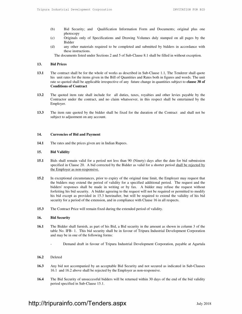
13. Bid Prices
13.1 The contract shall be for the whole of works as described in Sub-Clause 1.1, The Tenderer shall quote
his unit rates for the items given in the Bill of Quantities and Rates both in figures and words. The unit
rate so quoted shall be applicable irrespective of any future change in quantities subject to clause 38 of
Conditions of Contract
13.2 The quoted item rate shall include for all duties, taxes, royalties and other levies payable by the
Contractor under the contract, and no claim whatsoever, in this respect shall be entertained by the
Employer.
13.3 The item rate quoted by the bidder shall be fixed for the duration of the Contract and shall not be
subject to adjustment on any account.
14. Currencies of Bid and Payment
14.1 The rates and the prices given are in Indian Rupees.
15. Bid Validity
15.1 Bids shall remain valid for a period not less than 90 (Ninety) days after the date for bid submission
specified in Clause 20. A bid corrected by the Bidder as valid for a shorter period shall be rejected by
the Employer as non-responsive.
15.2 In exceptional circumstances, prior to expiry of the original time limit, the Employer may request that
the bidders may extend the period of validity for a specified additional period. The request and the
bidders' responses shall be made in writing or by fax. A bidder may refuse the request without
forfeiting his bid security. A bidder agreeing to the request will not be required or permitted to modify
his bid except as provided in 15.3 hereinafter, but will be required to extend the validity of his bid
security for a period of the extension, and in compliance with Clause 16 in all respects.
15.3 The Contract Price will remain fixed during the extended period of validity.
16. Bid Security
16.1 The Bidder shall furnish, as part of his Bid, a Bid security in the amount as shown in column 3 of the
table No. IFB- 1. This bid security shall be in favour of Tripura Industrial Development Corporation
and may be in one of the following forms:
- Demand draft in favour of Tripura Industrial Development Corporation, payable at Agartala
16.2 Deleted
16.3 Any bid not accompanied by an acceptable Bid Security and not secured as indicated in Sub-Clauses
16.1 and 16.2 above shall be rejected by the Employer as non-responsive.
16.4 The Bid Security of unsuccessful bidders will be returned within 30 days of the end of the bid validity
period specified in Sub-Clause 15.1.
http://tripurainfo.com/Tenders.aspx

Tripura Industrial Development Corporation INVITATION FOR BID
July 2018 13
16.5 The Bid Security of the successful bidder will be discharged when the bidder has signed the Agreement
and furnished the required Performance Security.
16.6 The Bid Security may be forfeited
(a) if the Bidder withdraws the Bid after Bid opening during the period of Bid validity;
(b) if the Bidder does not accept the correction of the Bid Price, pursuant to Clause 27; or
(c) in the case of a successful Bidder, if the Bidder fails within the specified time limit to
(i) sign the Agreement; or
(ii) furnish the required Performance Security.
16.7 No interest shall be paid on any Bid security/Performance Security/ or Guarantee in lieu thereof.
17. Alternative Proposals by Bidders
17.1 Alternative bids shall not be considered for any part of the Works.
18. Format and Signing of Bid
18.1 The Bidder shall prepare the Bid as specified in clause 12 and following the instructions in clause 19.
18.2 The original and copy of the Bid shall be typed or written in indelible ink and shall be signed by a
person or persons duly authorized to sign on behalf of the Bidder. All pages of the bid where entries or
amendments have been made shall be initialed by the person or persons signing the bid.
18.3 The Bid shall contain no alterations or additions, except those to comply with instructions issued by the
Employer, or as necessary to correct errors made by the bidder, in which case such corrections shall be
initialed by the person or persons signing the bid.
D. Submission of Bids
19. Sealing and Marking of Bids
19.1 There shall be two parts for the bids, Part “A” and Part “B”. The part ‘A’ shall contain Technical part of
the bid and Part “B” shall contain Financial part of the bid. The Bidder shall enclose the original and
one photocopy of Part A in one envelope marking it as, Envelope-A, TECHNICAL BID-ORIGINAL-
and COPY. He will then enclose the original and one photocopy of Part-B in another envelope
marking it as Envelope- B , FINANCIAL BID ORIGINAL- and COPY. These envelopes (called as
inner envelopes) shall then be put inside one outer envelope.
Part ‘A’, Technical BID of the bid shall contain,
i Bid Security as per tender requirement. If the Bid Security is not deposited the tender
shall be declared as non-responsive and rejected.
ii The Qualification Information indicated in Section 2, duly filled in original and
photocopy
iii A forwarding letter (in duplicate) from the Bidder shall clearly stating in the
forwarding letter ( in duplicate) to be enclosed with the tender document, the
deviation from general terms and conditions, if any, with cross references. If no such
letter is received, it will be presumed that the Bidder agrees entirely with the General
terms and Conditions.
iv. Book-1 Invitation for Bid, Book-2, Specifications, duly stamped and initialed on each
page by the tenderer as proof of their having scrutinized the documents.
Part B Financial bid shall contain
i Form of Bid duly filled in original plus photocopy
http://tripurainfo.com/Tenders.aspx

Tripura Industrial Development Corporation INVITATION FOR BID
July 2018 14
ii Book- 3, Bill of Quantities volume wherein the Bidder shall fill in the percentage
above the engineer’s estimate and each page duly signed and sealed.
19.2 The inner and outer envelopes shall
(a) be addressed to the Employer at the following address:
Tripura Industrial Development Corporation
Shilpa Nigam Bhavan,
Khejurbagan,
P.O Kunjaban, Agartala,
Tripura - 799006
(b) bear the following identification:
- Bid for Setting up of Land Custom Station at Muhurighat, Belonia, Tripura.
Bid Reference No.: TIDC/LCS/CIVIL/MUHURIGHAT/01/2018-19
- DO NOT OPEN BEFORE 15-30 Hours on 18th
July 2018.
19.3 In addition to the identification required in Sub-Clause 19.2, the inner envelopes shall indicate the name
and address of the bidder to enable the bid to be returned unopened in case it is declared late, pursuant
to Clause 21.
19.4 If the outer envelope is not sealed and marked as above, the Employer will assume no responsibility for
the misplacement or premature opening of the bid.
20. Deadline for Submission of the Bids
20.1 Bids must be received by the Employer at the address specified above no later than 15-00 hours on 18th
July 2018. In the event of the specified date for the submission of bids declared a holiday for the
Employer, the Bids will be received up to the appointed time on the next working day.
20.2 The Employer may extend the deadline for submission of bids by issuing an amendment in accordance
with Clause 10, in which case all rights and obligations of the Employer and the bidders previously
subject to the original deadline will then be subject to the new deadline.
21. Late Bids
21.1 Any Bid received by the Employer after the deadline prescribed in Clause 20 will be returned unopened
to the bidder.
22. Modification and Withdrawal of Bids
22.1 Bidders may modify or withdraw their bids by giving notice in writing before the deadline prescribed in
Clause 20.
22.2 Each Bidder's modification or withdrawal notice shall be prepared, sealed, marked, and delivered in
accordance with Clause 18 & 19, with the outer and inner envelopes additionally marked
"MODIFICATION" or "WITHDRAWAL", as appropriate.
22.3 No bid may be modified after the deadline for submission of Bids.
22.4 Withdrawal or modification of a Bid between the deadline for submission of bids and the expiration of
the original period of bid validity specified in Clause 15.1 above or as extended pursuant to Clause 15.2
may result in the forfeiture of the Bid security pursuant to Clause 16.
22.5 Bidders may offer discounts to, or modify the prices of their Bids only by submitting Bid modifications
in accordance with this clause, or included in the original Bid submission.
http://tripurainfo.com/Tenders.aspx

Tripura Industrial Development Corporation INVITATION FOR BID
July 2018 15
E. Bid Opening and Evaluation
23. Bid Opening
23.1 The Employer will open all the Bids received (except those received late), subject to the Bidder having
conformed to the submittal procedure set out in clause 19, including modifications made pursuant to
Clause 22, in the presence of the Bidders or their representatives who choose to attend at 15.30 Hours
on 18th
July 2018. In the event of the specified date of Bid opening being declared a holiday for the
Employer, the Bids will be opened at the appointed time and location on the next working day.
23.2 Envelopes marked "WITHDRAWAL" shall be opened and read out first. Bids for which an acceptable
notice of withdrawal has been submitted pursuant to Clause 22 shall not be opened. Subsequently all
envelopes marked “Modification” shall be opened and the submissions therein read out in appropriate
detail.
23.3 Bids not accompanied by specified Bid Security shall be considered non responsive and rejected
outright.
23.4 The financial bids of only those bidder who have obtained the qualification shall be opened only
after evaluating the Technical bids as explained in Clause 29.
23.5 The Employer shall prepare minutes of the Bid opening, including the information disclosed to those
present during the Bid Opening. Copies of the minutes shall be distributed to the bidders.
24. Process to Be Confidential
24.1 Information relating to the examination, clarification, evaluation, and comparison of Bids and
recommendations for the award of a contract shall not be disclosed to Bidders or any other persons not
officially concerned with such process until the award to the successful Bidder has been announced.
Any effort by a Bidder to influence the Employer's processing of Bids or award decisions may result in
the rejection of his Bid.
25. Clarification of Bids
25.1 To assist in the examination, evaluation, and comparison of Bids, the Employer may, at his discretion,
ask any Bidder for clarification of his Bid, including breakdowns of the unit rates. The request for
clarification and the response shall be in writing or by fax, but no change in the price or substance of
the Bid shall be sought, offered or permitted except as required to confirm the correction of arithmetic
errors discovered by the Employer in the evaluation of the Bids in accordance with Clause 27.
25.2 Subject to sub clause 25.1, no bidder shall contact the employer on any matter relating to its bid from
the time of the bid opening to the time the contract is awarded. If the bidder wishes to bring additional
information to the notice of employer, he should do so in writing.
25.3 Any effort by the Bidder to influence the Employer in the Employer's bid evaluation, bid comparison or
contract award decisions may result in the rejection of the Bidders’ bid.
26. Examination of Bids and Determination of Responsiveness
26.1 Prior to the detailed evaluation of Bids, the Employer will determine whether each Bid (a) meets the
eligibility criteria defined in Clause 3; (b) has been properly signed; (c) is accompanied by the required
securities and; (d) is substantially responsive to the requirements of the Bidding documents.
26.2 A substantially responsive Bid is one which conforms to all the terms, conditions, and specifications of
the Bidding documents, without material deviation or reservation. A material deviation or reservation is
one (a) which affects in any substantial way the scope, quality, or performance of the Works; (b) which
limits in any substantial way, inconsistent with the Bidding documents, the Employer's rights or the
http://tripurainfo.com/Tenders.aspx

Tripura Industrial Development Corporation INVITATION FOR BID
July 2018 16
Bidder's obligations under the Contract; or (c) whose rectification would affect unfairly the competitive
position of other Bidders presenting substantially responsive Bids.
26.3 If a Bid is not substantially responsive, it will be rejected by the Employer, and may not subsequently
be made responsive by correction or withdrawal of the non-conforming deviation or reservation.
27. Correction of Errors
27.1 Bids determined to be substantially responsive will be checked by the Employer for any arithmetic
errors. Errors will be corrected by the Employer as follows:
(a) where there is a discrepancy between the rates in figures and in words, the rate in words will
govern; and
(b) where there is a discrepancy between the unit and the line item total resulting from multiplying
the unit rate by the quantity, the unit rate as quoted will govern.
27.2 The amount stated in the Bid will be adjusted by the Employer in accordance with the above procedure
for the correction of errors and, with the concurrence of the Bidder, shall be considered as binding upon
the Bidder. If the Bidder does not accept the corrected amount the Bid will be rejected, and the Bid
security may be forfeited in accordance with Sub-Clause 16.6 (b).
28. Not applicable to this Contract
29. Evaluation and Comparison of Bids
29.1 The technical proposals shall be evaluated. based on the information submitted in the Qualification
Information and following the criteria set out below:
Experience of having successfully completed
one similar work costing not less Rs. 11.40
Crores in a single tender in 24 months in last
7 years
30
The Bidder should also have completed at
least one single contract of Road work of
value not less than Rs. 2 crores in the state of
Tripura/outside Tripura
20
Average Annual Financial Turnover during
last 3 years ending 31st March 2018, should
be at least 11 Crores
20
Solvency of Rs. 4.56 Crores 20
The Bidder should have P.F & ESI
registration with the concerned departments
10
Total Marks 100
The minimum qualification marks shall be 70.
29.2 The Employer will open , evaluate and compare the financial Bids of only those Bidders determined to
be substantially responsive in accordance with Clause 26 and also scoring the qualifying evaluation
marks as explained in clause 29.1. The remaining Financial Bids shall be returned unopened.
29.3 The Employer reserves the right to accept or reject any variation, deviation from the bid document, or
any alternative offer. Variations, deviations and alternative offers and other factors which are in excess
of the requirements of the Bidding documents or otherwise result in unsolicited benefits for the
Employer shall not be taken into account in Bid evaluation.
http://tripurainfo.com/Tenders.aspx

Tripura Industrial Development Corporation INVITATION FOR BID
July 2018 17
29.4 If the Bid of the successful Bidder is seriously unbalanced in relation to the Engineer's estimate of the
cost of work to be performed under the contract, the Employer may require the Bidder to produce
detailed price analyses for any or all items of the Bill of Quantities, to demonstrate the internal
consistency of those prices with the construction methods and schedule proposed. After evaluation of
the price analyses, the Employer may require that the amount of the performance security set forth in
Clause 33 be increased at the expense of the successful Bidder to a level sufficient to protect the
Employer against financial loss in the event of default of the successful Bidder under the Contract.
F. Award of Contract
30. Award Criteria
30.1 Subject to Clause 31, the Employer will negotiate if required with the bidder whose bid has been
determined to be substantially responsive to the Bidding documents and who has offered the lowest
evaluated Bid Price. On completion of negotiations the employer will award the contract to the lowest
bidder.
31. Employer's Right to Accept any Bid and to Reject any or all Bids
31.1 Notwithstanding Clause 30, the Employer reserves the right to accept or reject any Bid or part of the
Bid, and to cancel the Bidding process and reject all Bids, at any time prior to the award of Contract,
without thereby incurring any liability to the affected Bidder or Bidders or any obligation to inform
the affected Bidder or Bidders of the grounds for the Employer's action.
32. Notification of Award and Signing of Agreement
32.1 The Bidder whose Bid has been accepted will be notified of the award by the Employer prior to
expiration of the Bid validity period by fax confirmed by registered letter. This letter (hereinafter and in
the Conditions of Contract called the "Letter of Acceptance") will state the sum that the Employer will
pay the Contractor in consideration of the execution, completion, and maintenance of the Works by the
Contractor as prescribed by the Contract (hereinafter and in the Contract called the "Contract Price").
32.2 The notification of award will constitute the formation of the Contract, subject only to the furnishing of
a performance security in accordance with the provisions of Clause 33.
32.3 The Agreement will incorporate all agreements between the Employer and the successful Bidder. It will
be kept ready for signature of the successful bidder in the office of employer within 15 days following
the notification of award along with the Letter of Acceptance. Within 15 days of receipt of Letter of
Acceptance, the successful Bidder will sign the Agreement and deliver it to the Employer.
32.4 Upon accepting the Performance Security for the Successful Bidder and signing of the agreement, the
employer shall issue a ‘Notice to Proceed’ to the Contractor, in which the date of commencement of the
Contract shall be indicated.
32.5 Upon furnishing of the Performance Security by the successful Bidder, the Employer will promptly
notify the other Bidders that their Bids have been unsuccessful.
33. Performance Security
33.1 Within 15 days of receipt of the Letter of Acceptance, the successful Bidder shall deliver to the
Employer a Performance Security in any of the forms given below for an amount equivalent to 5 % of
the Contract price plus additional security for unbalanced Bids in accordance with Clause 29.4 of IFB
and Clause 52 of Conditions of Contract:
- Bank draft, in favour of Tripura Industrial Development Corporation payable at Agartala.
33.2 If the performance security is provided by the successful Bidder in the form of a Bank Guarantee, it
shall be at the Bidder's option, by a Nationalized/Scheduled Indian bank
http://tripurainfo.com/Tenders.aspx

Tripura Industrial Development Corporation INVITATION FOR BID
July 2018 18
33.3 Failure of the successful bidder to comply with the requirements of sub-clause 33.1 shall constitute a
breach of contract, cause for annulment of the award, forfeiture of the bid security, and any such other
remedy the Employer may take under the contract, and the Employer may resort to awarding the
contract to the next ranked bidder.
34 Advance Payment and Security
34.1 The Employer will provide an Advance Payment on the Contract Price as stipulated in the Conditions
of Contract, subject to maximum amount, as stated in the Contract Data.
35 Corrupt or Fraudulent Practices
35.1 The Employer expects the Bidders, Suppliers and Contractors observe the highest standard of ethics
during the procurement and execution of such contracts .Therefore ,the Employer
(a) defines, for the purposes of this provision, the terms set forth below as follows:
(i) “corrupt practice” means the offering, giving, receiving, or soliciting, directly or
indirectly, of anything of value to influence the action of the Employer in the
procurement process or in contract execution;
(ii) “fraudulent practice” means a misrepresentation or omission of facts in order to
influence a procurement process or the execution of a contract;
(iii) “collusive practice” means a scheme or arrangement between two or more Bidders,
with or without the knowledge of the Employer, designed to establish bid prices at
artificial, non competitive levels; and
(iv) “coercive practice” means harming or threatening to harm, directly or indirectly,
persons or their property to influence their participation in the procurement process or
affect the execution of a contract;
(b) will reject a proposal for award if it determines that the Bidder recommended for award has,
directly or through an agent, engaged in corrupt, fraudulent, collusive or coercive practices in
competing for the Contract in question;
http://tripurainfo.com/Tenders.aspx

Tripura Industrial Development Corporation INVITATION FOR BID
July 2018 19
SECTION-2
FORMS OF BID, QUALIFICATION INFORMATION AND LETTER OF ACCEPTANCE
Table of Forms:
- CONTRACTOR’S BID*
- QUALIFICATION INFORMATION*
- LETTER OF ACCEPTANCE
- NOTICE TO PROCEED WITH THE WORK
- AGREEMENT FORM
NOTE :-
* BOTH THESE FORMS ARE TO BE FILLED IN BY THE TENDERER AND RETURNED AS PART OF
HIS BID.
http://tripurainfo.com/Tenders.aspx

Tripura Industrial Development Corporation INVITATION FOR BID
July 2018 20
Contractor's Bid
Description of the Works : Setting Up of Land Custom Station at Muhurighat, Belonia, Tripura
BID No. : TIDC/LCS/CIVIL/MUHURIGHAT/01/2018-19
To : Managing Director,
Address: Tripura Industrial Development Corporation
Shilpa Nigam Bhavan,
Khejurbagan,
P.O Kunjaban, Agartala,
Tripura - 799006
GENTLEMEN,
Having examined the bidding documents including addendum, we offer to execute the Works described above in
accordance with the Conditions of Contract, Specifications, Drawings and Bill of Quantities accompanying this
Bid, for a contract price of Rs._______________ (Rupees
__________________________________________________)
This bid shall be valid for a period of 90 ( Ninety ) days from the day the bid is opened.
This Bid and your written acceptance of it shall constitute a binding contract between us. We understand that
you are not bound to accept the lowest or any Bid you receive.
We hereby certify that we have taken steps to ensure that no person acting for us or on our behalf will engage in
bribery.
We also undertake that, in competing for (and, if the award is made to us, in executing) the above contract, we
will strictly observe the laws against fraud and corruption in force in India namely “Prevention of Corruption Act
1988”
We hereby confirm that this Bid complies with the Eligibility, Bid Validity and Bid Security required by the
Bidding documents.
Yours faithfully,
Authorized Signature:
Name & Title of Signatory: ____________________________________________
Name of Bidder : ____________________________________________
Address : _____________________________________________
Company Seal/Stamp
http://tripurainfo.com/Tenders.aspx
Tripura Industrial Development Corporation INVITATION FOR BID
July 2018 21
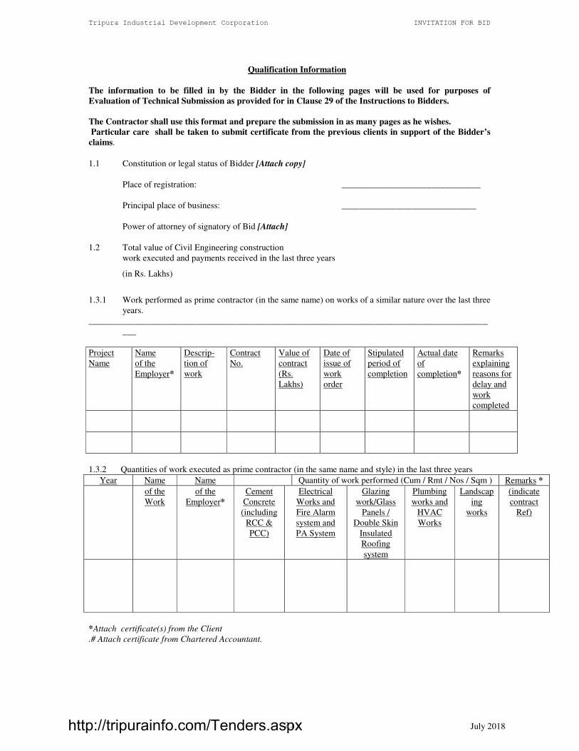
Qualification Information
The information to be filled in by the Bidder in the following pages will be used for purposes of
Evaluation of Technical Submission as provided for in Clause 29 of the Instructions to Bidders.
The Contractor shall use this format and prepare the submission in as many pages as he wishes.
Particular care shall be taken to submit certificate from the previous clients in support of the Bidder’s
claims.
1.1 Constitution or legal status of Bidder [Attach copy]
Place of registration: _______________________________
Principal place of business: ______________________________
Power of attorney of signatory of Bid [Attach]
1.2 Total value of Civil Engineering construction
work executed and payments received in the last three years
(in Rs. Lakhs)
1.3.1 Work performed as prime contractor (in the same name) on works of a similar nature over the last three
years.
_________________________________________________________________________________________
___
Project
Name
Name
of the
Employer*
Descrip-
tion of
work
Contract
No.
Value of
contract
(Rs.
Lakhs)
Date of
issue of
work
order
Stipulated
period of
completion
Actual date
of
completion*
Remarks
explaining
reasons for
delay and
work
completed
1.3.2 Quantities of work executed as prime contractor (in the same name and style) in the last three years
Year Name Name Quantity of work performed (Cum / Rmt / Nos / Sqm ) Remarks *
of the
Work
of the
Employer*
Cement
Concrete
(including
RCC &
PCC)
Electrical
Works and
Fire Alarm
system and
PA System
Glazing
work/Glass
Panels /
Double Skin
Insulated
Roofing
system
Plumbing
works and
HVAC
Works
Landscap
ing
works
(indicate
contract
Ref)
*Attach certificate(s) from the Client
.# Attach certificate from Chartered Accountant.
http://tripurainfo.com/Tenders.aspx

Tripura Industrial Development Corporation INVITATION FOR BID
July 2018 22
1.4 Information on Bid Capacity (works for which bids have been submitted and works which are yet to be
completed) as on the date of this bid.
(A) Existing commitments and on-going works:
______________________________________________________________________________
Description Place Contract No. Name Value of Stipulated Value of works* Anticipated
of & & Date and Contract period of remaining to be date of
Work State Address (Rs. lakhs) completion completed completion
of Employer (Rs. lakhs)
(1) (2) (3) (4) (5) (6) (7) (8)
_________________________________________________________________________________________
________________________________________________________________________________________
(B) Works for which bids already submitted:
_________________________________________________________________________________________
Description Place Name and Estimated Stipulated Date when
Remarks
of & Address of value of works period of decision is if any
Work State Employer (Rs. lakhs) completion expected
(1) (2) (3) (4) (5) (6) (7)
* Attach certificate(s) from Client.
1.5 Contractor's Plant and Equipment essential for carrying out the Works shall be listed below.
________________________________________________________________________________________
_______________________________________________________________________________________
Item of Requirement Availability / proposals
Equipment No. Capacity Owned/leased/ Nos/ Age/
to be procured capacity condition
_______________________________________________________________________________________
1. Hydraulic excavator
2. Dozer
3 Water tanker
4. Vibrator
5. Power Roller
6. Plate Compactor
7. Concrete Mixer
8. Tippers/Trucks
http://tripurainfo.com/Tenders.aspx

Tripura Industrial Development Corporation INVITATION FOR BID
July 2018 23
1.6 Qualifications and experience of key personnel proposed for administration and execution of the
Contract. Attach biographical data. Refer to Sub Clause 9.1 of the Conditions of Contract.
__________________________________________________________________________________
Minimum Years of Years of experience in
Position Name Qualifications experience the proposed position
(general)
__________________________________________________________________________________
Project Manager (1 No) Civil Engineering Graduate 10 7
Site Engineers (2 Nos.) Civil Engineering Graduate 7 5
Quantity Surveyor (1 No) Civil Engineering Graduate 5 3
Material Engineer (1 No) Civil Engineering Graduate 5 3
Electrical Cum HVAC Electrical Engineering Graduate 5 3
Engineer (1No)
Water Supply Engineer Civil Engineering Graduate 5 3
Engineer (1No)
_________________________________________________________________________________
1.7 A statement regarding the number of Skilled and unskilled workers, the company has on its rolls at the
time of tender submission. The statement also should indicate the number of skilled and unskilled
workers proposed to be deployed on this project.
1.8 Proposed subcontracts and firms involved.
__________________________________________________________________________________
Sections Value of Sub-contractor Experience in
of the works Sub-contract (name and address) similar work
__________________________________________________________________________________
__________________________________________________________________________________
1.9 Evidence of access to financial resources to meet the qualification requirements: cash in hand, lines of
credit, etc. List them below and attach copies of support documents [sample format attached].
1.10. Name, address, and telephone, telex, and fax numbers of the Bidders' bankers who may provide
references if contacted by the Employer.
1.11 Information on litigation history in which the Bidder is involved.
__________________________________________________________________________________
Other party(ies) Employer Cause of dispute Amount involved Remarks showing
Present status
__________________________________________________________________________________
__________________________________________________________________________________
1.12 Statement of compliance under the requirements of Sub Clause 4.0 of the instructions to Bidders.
1.13 Proposed work method and schedule. The Bidder should attach descriptions, drawings and charts as
necessary to comply with the requirements of the Bidding documents.
http://tripurainfo.com/Tenders.aspx

Tripura Industrial Development Corporation INVITATION FOR BID
July 2018 24
SAMPLE FORMAT FOR EVIDENCE OF ACCESS TO OR AVAILABILITY OF CREDIT
FACILITIES –*
BANK CERTIFICATE
This is to certify that M/s. …………………………… is a reputed company with a good financial standing.
If the contract for the work, namely ………………………………………………………………………………..
is awarded to the above firm, we shall be able to provide overdraft/credit facilities to the extent of Rs.
…………… to meet their working capital requirements for executing the above contract.
__ Sd. __
Name of Bank
Senior Bank Manager
Address of the Bank
http://tripurainfo.com/Tenders.aspx

Tripura Industrial Development Corporation INVITATION FOR BID
July 2018 25
Letter of Acceptance
(letterhead paper of the Employer)
____- ____ - 2018
To: ___________________________________________________________[name and address of the
Contractor]
Dear Sirs,
This is to notify you that your Bid dated ____________ for execution of the
__________________________
______________________________________________________________________ (Bid No.
_______________) for the Contract Price of Rs. _________________
(Rupees_______________________________________________
____________________________________) as corrected and modified in accordance with the Instructions to
Bidders1 is hereby accepted by our Agency.
We note that as per bid, you do not intend to subcontract any component of work.
[OR]
We note that as per bid, you propose to employ M/s. .......................................... as sub-contractor for
executing ….........................................
[Delete whichever is not applicable]
You are hereby requested to furnish Performance Security, plus additional security for unbalanced bids in
terms of ITB clause 29.4, in the form detailed in Para 33.1 of ITB for an amount of Rs.————— within 15
days of the receipt of this letter of acceptance valid up to 28 days from the date of expiry of Defects Liability
Period i.e. upto ........... and sign the contract, failing which action as stated in Para 33.3 of ITB will be taken.
Yours faithfully,
Managing Director,
Tripura Industrial Development Corporation (TIDC)
Shilpa Nigam Bhawan,
Khejurbagan,
P.O Kunjaban, Agartala,
Tripura - 799006
http://tripurainfo.com/Tenders.aspx

Tripura Industrial Development Corporation INVITATION FOR BID
July 2018 26
Notice to proceed with the work
(letterhead of the Employer)
————— (date)
To
—————————————— (name and address of the Contractor)
——————————————
——————————————
Dear Sirs:
Pursuant to your furnishing the requisite security as stipulated in IFB clause 33.1 and signing of the
contract agreement for the
________________________________________________________________________ @ a Bid Price of
Rs.____________ (Rupees __________________________________________________________ ) you are
hereby instructed to proceed with the execution of the said works in accordance with the contract documents.
The date of commencement will be ______________
Yours faithfully,
Managing Director,
SPV
http://tripurainfo.com/Tenders.aspx
Tripura Industrial Development Corporation INVITATION FOR BID
July 2018 27
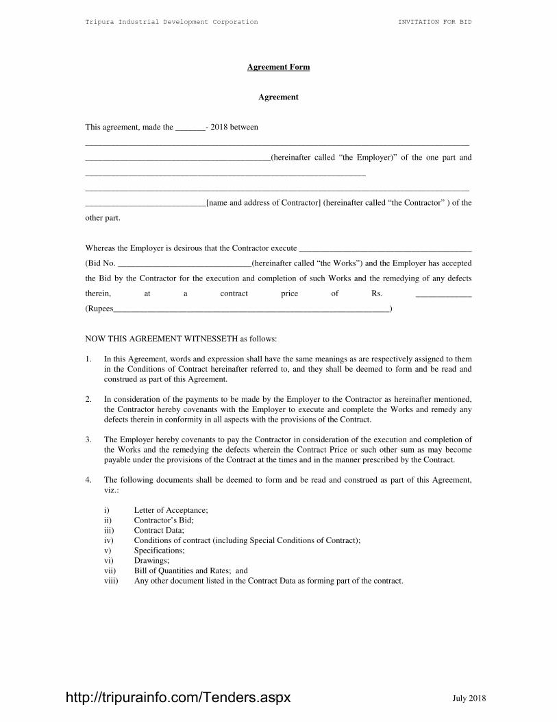
Agreement Form
Agreement
This agreement, made the _______- 2018 between
_________________________________________________________________________________________
___________________________________________(hereinafter called “the Employer)” of the one part and
_________________________________________________________________
_________________________________________________________________________________________
____________________________[name and address of Contractor] (hereinafter called “the Contractor” ) of the
other part.
Whereas the Employer is desirous that the Contractor execute ________________________________________
(Bid No. _______________________________(hereinafter called “the Works”) and the Employer has accepted
the Bid by the Contractor for the execution and completion of such Works and the remedying of any defects
therein, at a contract price of Rs. _____________
(Rupees________________________________________________________________)
NOW THIS AGREEMENT WITNESSETH as follows:
1. In this Agreement, words and expression shall have the same meanings as are respectively assigned to them
in the Conditions of Contract hereinafter referred to, and they shall be deemed to form and be read and
construed as part of this Agreement.
2. In consideration of the payments to be made by the Employer to the Contractor as hereinafter mentioned,
the Contractor hereby covenants with the Employer to execute and complete the Works and remedy any
defects therein in conformity in all aspects with the provisions of the Contract.
3. The Employer hereby covenants to pay the Contractor in consideration of the execution and completion of
the Works and the remedying the defects wherein the Contract Price or such other sum as may become
payable under the provisions of the Contract at the times and in the manner prescribed by the Contract.
4. The following documents shall be deemed to form and be read and construed as part of this Agreement,
viz.:
i) Letter of Acceptance;
ii) Contractor’s Bid;
iii) Contract Data;
iv) Conditions of contract (including Special Conditions of Contract);
v) Specifications;
vi) Drawings;
vii) Bill of Quantities and Rates; and
viii) Any other document listed in the Contract Data as forming part of the contract.
http://tripurainfo.com/Tenders.aspx

Tripura Industrial Development Corporation INVITATION FOR BID
July 2018 28
In witness whereof the parties thereto have caused this Agreement to be executed the day and year first before In
witness whereof the parties thereto have caused this Agreement to be executed the day and year first before
written.
For (Name of SPV)
Signed by Mr. (Name of SPV), in the presence of the following witnesses.
Binding Signature of Employer:
Employer: Common Seal of the Company
(Authorized Signatory for Affixing
Common Seal)
Witnesses
Signature: ________________________ Signature: ________________________
Name: ___________________________ Name: ___________________________
Address: _________________________ Address: __________________________
________________________________ _________________________________
________________________________ _________________________________
For (Contractor name)
Signed by Mr.
(Contractor name) in the presence of the following witnesses.
Binding Signature of Contractor:
Contractor: Common Seal of the Company
(Authorized Signatory for Affixing Common Seal)
Witnesses
Signature: ________________________ Signature: ________________________
Name: ___________________________ Name: ___________________________
Address: _________________________ Address: __________________________
________________________________
_________________________________
http://tripurainfo.com/Tenders.aspx

Tripura Industrial Development Corporation INVITATION FOR BID
July 2018 29
SECTION 3: CONDITIONS OF CONTRACT
http://tripurainfo.com/Tenders.aspx

Tripura Industrial Development Corporation INVITATION FOR BID
July 2018 30
Conditions of Contract
Table of Contents
Page No. Page
No.
A. General 31 C. Quality Control 38
1 Definitions 31 33 Identifying Defects 38
2 Interpretation 32 34 Tests 39
3 Language and Law 32 35 Correction of Defects 39
4 Engineer's Decisions 32 36 Uncorrected Defects 39
5 Delegation 33
6 Communications 33
7. Subcontracting 33 D. Cost Control 39
8. Other Contractors 34 37 Bill of Quantities 39
9. Personnel 34 38 Changes in the Quantities 39
10. Force Majeure 34 39 Variations 39
11. Exclusion from Force Majeure 34 40 Payments for Variations 39
12. Consequences of Force Majeure 34 41 Cash Flow Forecasts 40
13. Insurance 35 42 Payment Certificates 40
14. Site Investigation Reports 35 43 Payments 40
15. Queries about the Contract Data 35 44 Compensation Events 41
16. Contractor to Construct the Works 35 45 Tax 42
17. The Works to Be Completed by 46 Currencies 42
the Intended Completion Date 36 47 Price Adjustments 42
18 Approval by the Engineer 36 48 Retention 42
19 Safety 36 49 Liquidated Damages 42
20 Discoveries 36 50 Bonus 43
21 Possession of the Site 36 51 Advance Payment 43
22 Access to the Site 36 52 Performance Securities 43
23 Instructions 36 53 Day works 43
24 Disputes 36 54 Defect Liability and Cost of Repairs 44
25 Procedure for Disputes 36
E. Finishing the Contract 44
55 Completion 44
B. Time Control 37 56 Taking Over 44
27 Program 37 57 Final Account 44
28 Extension of the Intended 58 As Built Drawings 44
Completion Date 38 59 Termination 44
29 Acceleration 38 60 Payment upon Termination 45
30 Delays Ordered by the Engineer 38 61 Property 45
62 Release from Performance 45
31 Management Meetings 38
32 Early Warning 38 Special Conditions of Contract 46
http://tripurainfo.com/Tenders.aspx

Tripura Industrial Development Corporation INVITATION FOR BID
July 2018 31
General Conditions of Contract
A. General
1. Definitions
1.1 Terms which are defined in the Contract Data are not also defined in the Conditions of Contract but
keep their defined meanings. Capital initials are used to identify defined terms.
Bill of Quantities and Rates means the priced and completed Bill of Quantities and Rates forming
part of the Bid.
Compensation Events are those defined in Clause 44 hereunder.
The Completion Date is the date of completion of the Works as certified by the Construction Manager
in accordance with Sub Clause 55.1.
The Contract is the contract between the Employer and the Contractor to execute, complete and
maintain the Works. It consists of the documents listed in Clause 2.3 below.
The Contract Data defines the documents and other information which comprise the Contract.
The Contractor is a person or corporate body whose Bid to carry out the Works has been accepted by
the Employer.
The Contractor's Bid is the completed Bidding document submitted by the Contractor to the
Employer.
The Contract Price is the price stated in the Letter of Acceptance and thereafter as adjusted in
accordance with the provisions of the Contract.
Date of Commencement is the date as stated in the letter to proceed from the employer to the
contractor.
Days are calendar days; months are calendar months.
A Defect is any part of the Works not completed in accordance with the Contract.
The Defects Liability Period is the period named in the Contract Data and calculated from the
Completion Date.
The Employer is the party who will employ the Contractor to carry out the Works.
Construction Manager / Engineer is IL&FS Cluster Development Initiative Limited (the person
appointed by the employer as to deal to all the matters related to the execution and operation of the
contract).
Construction Manager’s Representative or Engineer’s Representative shall be appointed by the
Construction Manager and be responsible to the Construction Manager and shall carry out such duties
and exercise such authority as may be delegated to him by the Construction Manager.
Equipment is the Contractor's machinery and vehicles brought temporarily to the Site to construct the
Works.
The Initial Contract Price is the Contract Price listed in the Employer's Letter of Acceptance.
The Intended Completion Date is the date on which it is intended that the Contractor shall complete
the Works. The Intended Completion Date is specified in the Contract Data. The Intended Completion
Date may be revised only by the Construction Manager by issuing an extension of time.
http://tripurainfo.com/Tenders.aspx

Tripura Industrial Development Corporation INVITATION FOR BID
July 2018 32
Materials are all supplies, including consumables, used by the Contractor for incorporation in the
Works.
Plant is any integral part of the Works which is to have a mechanical, electrical, electronic or chemical
or biological function.
The Site is the area defined as such in the Contract Data.
Site Investigation Reports are those which were included in the Bidding documents and are factual
interpretative reports about the surface and sub-surface conditions at the site.
Specification means the Specification of the Works included in the Contract and any modification or
addition made or approved by the Engineer.
A Sub-contractor is a person or corporate body who has a Contract with the Contractor to carry out a
part of the work in the Contract which includes work on the Site.
Temporary Works are works designed, constructed, installed, and removed by the Contractor which
are needed for construction or installation of the Works.
A Variation is an instruction given by the Construction Manger which varies the Works.
The Works are what the Contract requires the Contractor to construct, install, and turn over to the
Employer, as defined in the Contract Data.
2. Interpretation
2.1 In interpreting these Conditions of Contract, singular also means plural, male also means female or
neuter, and the other way around. Headings have no significance. Words have their normal meaning
under the language of the Contract unless specifically defined. The Construction Manager will provide
instructions clarifying queries about the Conditions of Contract.
2.2 If sectional completion is specified in the Contract Data, references in the Conditions of Contract to the
Works, the Completion Date, and the Intended Completion Date apply to any Section of the Works
(other than references to the Completion Date and Intended Completion date for the whole of the
Works).
2.3 The documents forming the Contract shall be as follows and their order of priority shall be interpreted
in the given order
(1) Agreement
(2) Letter of Acceptance, Notice to proceed with work.
(3) Contractor’s Bid
(4) Contract Data
(5) Conditions of Contract including Special Conditions of Contract
(6) Specifications
(7) Drawings
(8) Bill of Quantities
(9) any other document listed in the Contract Data as forming part of the Contract.
3. Language and Law
3.1 The language of the Contract and the law governing the Contract are stated in the Contract Data.
4. Construction Managers Decisions
4.1 Except where otherwise specifically stated, the Construction Manager will decide contractual matters
between the Employer and the Contractor in the role representing the Employer.
http://tripurainfo.com/Tenders.aspx

Tripura Industrial Development Corporation INVITATION FOR BID
July 2018 33
5. Delegation
5.1 The Construction Manager may delegate any of his duties and responsibilities to other people after
notifying the Contractor and may cancel any delegation after notifying the Contractor.
6. Communications
6.1 Communications between parties which are referred to in the conditions are effective only when in
writing. A notice shall be effective only when it is delivered (in terms of Indian Contract Act).
7. Subcontracting
7.1 a) All bidders are expected to indicate clearly in the bid, if they propose sub-contracting elements of
the works amounting to more than 20 percent of the Bid Price. For each such proposal the qualification
and the experience of the identified Sub-contractor in the relevant field should be furnished along with
the bid to enable the Employer to satisfy himself about their qualifications before agreeing for such
sub-contracting and include it in the contract. In view of the above, normally no additional sub-
contracting should arise during execution of the contract.
b) However, [a] sub contracting for certain specialized elements of the work is not unusual and will be
acceptable for carrying out the works more effectively; but vertical splitting of the works for
subcontracting is not acceptable. [b] In any case, proposal for sub-contracting in addition to what was
specified in bid and stated in contract agreement will not be acceptable if the value of such additional
sub-contracting exceeds 20% of value of work which was to be executed by Contractor without sub-
contracting.
c) Assignment of the contract may be acceptable only under exceptional circumstances such as
insolvencies/liquidation or merger of companies etc.
d) The Contractor may subcontract with the approval of the Engineer / Construction Manager but may
not assign the Contract without the approval of the Employer in writing. Subcontracting does not alter
the Contractor's obligations.
7.2. The Contractor shall not be required to obtain any consent from the Employer for:
a) the sub-contracting of any part of the Works for which the Sub-contractor is named in the contract;
b) the provision of labour; and
c) the purchase of materials which are in accordance with the standards specified in the Contract.
Beyond this if the Contractor proposes sub-contracting any part of the work during execution of works,
because of some unforeseen circumstances to enable him to complete the work as per terms of the
contract, the Engineer / Construction Manager will consider the following before according approval:
The Contractor shall not sub-contract the whole of the Works.
The Contractor shall not sub-contract any part of the Work without prior consent of the Construction
Manager. Any such consent shall not relieve the Contractor from any liability or obligations under the
contract and he shall be responsible for the acts, defaults and neglects of any Sub-contractor, his agents
or workmen as fully as if they were the acts, defaults or neglects of the Contractor, his agents or
workmen.
They should satisfy whether (a) the circumstances warrant such sub-contracting; and (b) the Sub-
contractors so proposed for the Work possess the experience, qualifications and equipment necessary
for the job proposed to be entrusted to them in proportion to the quantum of work to be sub-contracted.
http://tripurainfo.com/Tenders.aspx
Tripura Industrial Development Corporation INVITATION FOR BID
July 2018 34
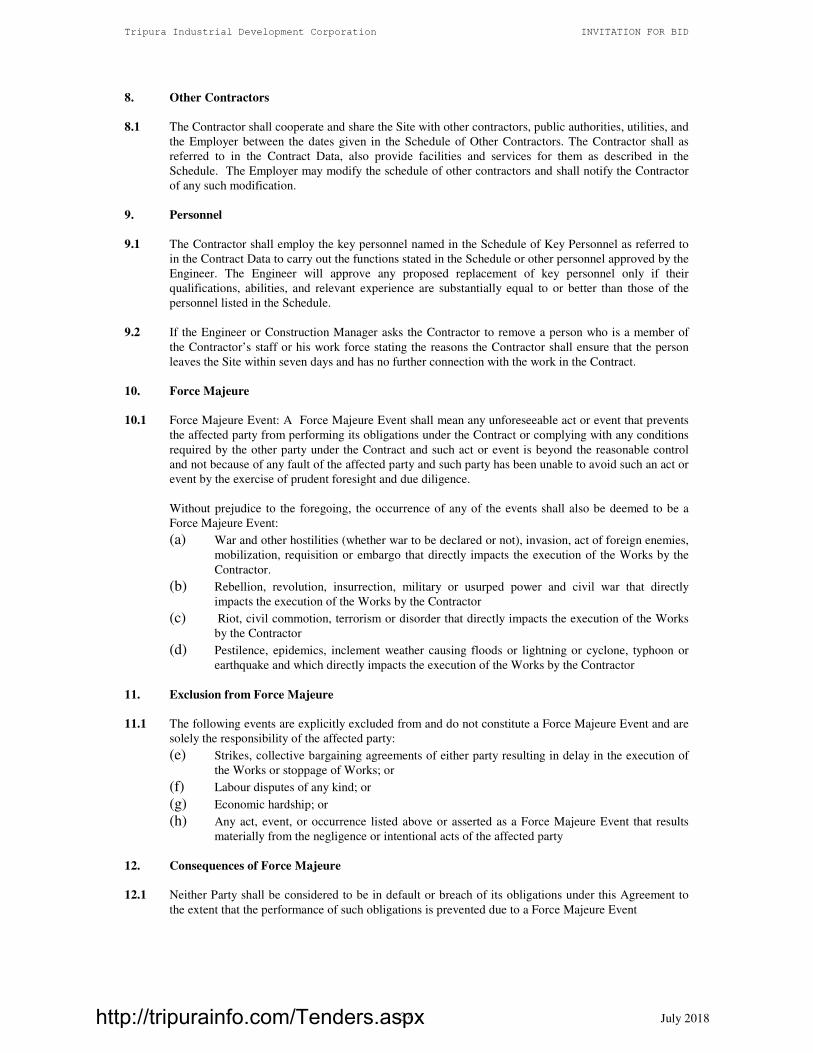
8. Other Contractors
8.1 The Contractor shall cooperate and share the Site with other contractors, public authorities, utilities, and
the Employer between the dates given in the Schedule of Other Contractors. The Contractor shall as
referred to in the Contract Data, also provide facilities and services for them as described in the
Schedule. The Employer may modify the schedule of other contractors and shall notify the Contractor
of any such modification.
9. Personnel
9.1 The Contractor shall employ the key personnel named in the Schedule of Key Personnel as referred to
in the Contract Data to carry out the functions stated in the Schedule or other personnel approved by the
Engineer. The Engineer will approve any proposed replacement of key personnel only if their
qualifications, abilities, and relevant experience are substantially equal to or better than those of the
personnel listed in the Schedule.
9.2 If the Engineer or Construction Manager asks the Contractor to remove a person who is a member of
the Contractor’s staff or his work force stating the reasons the Contractor shall ensure that the person
leaves the Site within seven days and has no further connection with the work in the Contract.
10. Force Majeure
10.1 Force Majeure Event: A Force Majeure Event shall mean any unforeseeable act or event that prevents
the affected party from performing its obligations under the Contract or complying with any conditions
required by the other party under the Contract and such act or event is beyond the reasonable control
and not because of any fault of the affected party and such party has been unable to avoid such an act or
event by the exercise of prudent foresight and due diligence.
Without prejudice to the foregoing, the occurrence of any of the events shall also be deemed to be a
Force Majeure Event:
(a) War and other hostilities (whether war to be declared or not), invasion, act of foreign enemies,
mobilization, requisition or embargo that directly impacts the execution of the Works by the
Contractor.
(b) Rebellion, revolution, insurrection, military or usurped power and civil war that directly
impacts the execution of the Works by the Contractor
(c) Riot, civil commotion, terrorism or disorder that directly impacts the execution of the Works
by the Contractor
(d) Pestilence, epidemics, inclement weather causing floods or lightning or cyclone, typhoon or
earthquake and which directly impacts the execution of the Works by the Contractor
11. Exclusion from Force Majeure
11.1 The following events are explicitly excluded from and do not constitute a Force Majeure Event and are
solely the responsibility of the affected party:
(e) Strikes, collective bargaining agreements of either party resulting in delay in the execution of
the Works or stoppage of Works; or
(f) Labour disputes of any kind; or
(g) Economic hardship; or
(h) Any act, event, or occurrence listed above or asserted as a Force Majeure Event that results
materially from the negligence or intentional acts of the affected party
12. Consequences of Force Majeure
12.1 Neither Party shall be considered to be in default or breach of its obligations under this Agreement to
the extent that the performance of such obligations is prevented due to a Force Majeure Event
http://tripurainfo.com/Tenders.aspx

Tripura Industrial Development Corporation INVITATION FOR BID
July 2018 35
13. Insurance
13.1 The Employer will provide all risk policy for works as given in the contract data.
13.2 The contractor shall provide, in the joint names of the Employer and the Contractor, insurance cover
from the Start Date to the end of the Defects Liability Period, in the amounts and deductibles stated in
the Contract Data for the following events which are due to the Contractor’s risks:
(a) loss of or damage to Contractor’s Equipment;
(b) loss of or damage of property (Except the Works) in connection with the Contractor
(c) personal injury or death.
13.3 Policies and certificates for insurance shall be delivered by the contractor to the engineer for the
engineers approval before the start date All such insurance shall provide for compensation to be
payable in the types and proportions of amount required to rectify the loss or damage incurred.
13.4 If the contractor does not provide any of the policies and certificates required, the employer may effect
the insurance which the contractor should have provided and recover the premiums paid by the
employer from payments due to the contractor or, if no payment is due, the payment of the premiums
shall be a debt due.
13.5 Alterations to the terms of insurance shall not be made without the approval of the engineer.
13.6 Both the parties shall comply with any conditions of the insurance policies.
13.7 It will be the responsibility of the contractor to bear the losses upto minimum deductible under the
insurance policies for each and every claim
13.8 The contractor shall do all the necessary requirements as per the terms of insurance for any claim. The
employer will assist the contractor in recovering the claim as per the terms of insurance. However in the
event of accidents, insurance claims recovery shall not vitiate the obligation of the contractor with
regard to executions of project as per schedule.
14. Site Investigation Reports
14.1 The Bidder shall be given a copy of the Site investigation report. The Report is only preliminary and
the Contractor upon award of Contract is expected to make his own investigation to establish the soil
and foundation conditions. The Contractor, in preparing the Bid, shall rely on the Site Investigation
Reports referred to in the Contract Data, supplemented by any information available to the Bidder,
However, such reference to the site investigation report shall not transfer any of the Contractor’s
responsibility to the Employer nor shall enable the Contractor to make any claim on the Employer on
the basis of information available or not available in the Site Investigation Report.
15. Queries about the Contract Data
15.1 The Construction Manager will clarify queries on the Contract Data.
16. Contractor to Construct the Works
16.1 The Contractor shall construct and install the Works in accordance with the Specification and
Drawings, and as per instructions of Engineer.
17. The Works to Be Completed by the Intended Completion Date
17.1 The Contractor may commence execution of the Works on the Date of commencement and shall carry
out the Works in accordance with the program submitted by the Contractor, as updated with the
approval of the Engineer, and complete them by the Intended Completion Date.
http://tripurainfo.com/Tenders.aspx

Tripura Industrial Development Corporation INVITATION FOR BID
July 2018 36
18. Approval by the Engineer
18.1 The Contractor shall submit Specifications and Drawings showing the proposed Temporary Works to
the Engineer, who is to approve them if they comply with the Specifications and Drawings.
18.2 The Contractor shall be responsible for design of Temporary Works.
18.3 The Engineer's approval shall not alter the Contractor's responsibility for design of the Temporary
Works.
18.4 The Contractor shall obtain approval of third parties to the design of the Temporary Works where
required.
18.5 All Drawings prepared by the Contractor for the execution of the temporary or permanent Works, are
subject to prior approval by the Engineer before their use.
19. Safety
19.1 The Contractor shall be responsible for the safety of all activities on the Site.
20. Discoveries
20.1 Anything of historical or other interest or of significant value unexpectedly discovered on the Site is
the property of the Employer. The Contractor is to notify the Construction Manager of such discoveries
and carry out the Construction Managers instructions for dealing with them.
21. Possession of the Site
21.1 The Employer shall give possession of all parts of the Site to the Contractor. If possession of a part is
not given by the date stated in the Contract Data, the Employer is deemed to have delayed the start of
the relevant activities and this will be Compensation Event.
22. Access to the Site
22.1 The Contractor shall allow the Construction Manager, Engineer and any person authorized by the
Construction Manager or Engineer access to the Site, to any place where work in connection with the
Contract is being carried out or is intended to be carried out and to any place where materials or plant
are being manufactured / fabricated / assembled for the works.
23. Instructions
23.1 The Contractor shall carry out all instructions of the Engineer which comply with the applicable laws
where the Site is located.
24. Disputes
24.1 If the Contractor believes that a decision taken by the Construction Manager or Engineer was either
outside the authority given to the Construction Manager or Engineer by the Contract or that the decision
was wrongly taken, the decision shall be referred to the Conciliator within 28 days of the notification of
the Engineer / Construction Manager’s decision.
25. Procedure for Disputes
25.1 The Arbitration shall be conducted in accordance with the arbitration procedure stated below.
The procedure for arbitration will be as follows :
(a) In case of Dispute or difference arising between the Employer and a domestic contractor relating to
any matter arising out of or connected with this agreement, such disputes or difference shall be settled
http://tripurainfo.com/Tenders.aspx

Tripura Industrial Development Corporation INVITATION FOR BID
July 2018 37
in accordance with the Arbitration and Conciliation Act, 1996. The arbitral tribunal shall consist of 3
arbitrators one each to be appointed by the Employer and the Contractor. The third Arbitrator shall be
chosen by the two Arbitrators so appointed by the Parties and shall act as Presiding arbitrator. In case
of failure of the two arbitrators appointed by the parties to reach upon a consensus within a period of 30
days from the appointment of the arbitrator appointed subsequently, the Presiding Arbitrator shall be
appointed by the * Indian Council of Arbitration/President of the Institution of Engineers (India)/The
International Centre for Alternative Dispute Resolution (India).
(b) If one of the parties fails to appoint its arbitrator in pursuance of sub-clause (a) and (b) above within
30 days after receipt of the notice of the appointment of its arbitrator by the other party, then the *
Indian Council of Arbitration/President of the Institution of Engineers (India)/The International Centre
for Alternative Dispute Resolution (India), both in cases of the Foreign Contractor as well as Indian
Contractor, shall appoint the arbitrator. A certified copy of the order of the *Indian Council of
Arbitration /President of the Institution of Engineers (India)/The International Centre for Alternative
Disputes Resolution (India), making such an appointment shall be furnished to each of the parties.
(c) Arbitration proceedings shall be at Agartala, Tripura , India, and the language of the arbitration
proceedings and that of all documents and communications between the parties shall be English.
(d) The decision of the majority of arbitrators shall be final and binding upon both parties. The cost
and expenses of Arbitration proceedings will be paid as determined by the arbitral tribunal. However,
the expenses incurred by each party in connection with the preparation, presentation, etc. of its
proceedings as also the fees and expenses paid to the arbitrator appointed by such party or on its behalf
shall be borne by each party itself.
(e) Where the value of the contract is Rs.500 Lakhs and below, the disputes or differences arising shall
be referred to the Sole Arbitrator. The Sole Arbitrator should be appointed by agreement between the
parties; failing such agreement, by the appointing authority, namely the Indian Council of
Arbitration/President of the Institution of Engineers (India)/The International Centre for Alternative
Disputes Resolution (India).
(f) Performance under the contract shall continue during the arbitration proceedings and payments due
to the contractor by the owners shall not be withheld, unless they are the subject matter of the
arbitration proceedings.
26. Deleted
B. Time Control
27. Program
27.1 Within the time stated in the Contract Data the Contractor shall submit to the Engineer for approval a
Construction Program including Environmental Management Plan showing the general methods,
arrangements, order, and timing for all the activities in the Works along with monthly cash flow
forecast and Resource Plan.
A format for submission of Progress Report shall be got approved by the Engineer. During the progress
of the work, the Engineer may suggest modification to the format, in which case, the contractor shall
follow the directions strictly.
27.2 An update of the Program shall be a program showing the actual progress achieved on each activity and
the effect of the progress achieved on the timing of the remaining work including any changes to the
sequence of the activities.
27.3 The Contractor shall submit to the Engineer, for approval, an updated Program at intervals no longer
than the period stated in the Contract Data. If the Contractor does not submit an updated Program
within this period, the Engineer may withhold the amount stated in the Contract Data from the next
http://tripurainfo.com/Tenders.aspx

Tripura Industrial Development Corporation INVITATION FOR BID
July 2018 38
payment certificate and continue to withhold this amount until the next payment after the date on which
the overdue Program has been submitted.
27.4 The Engineer's approval of the Program shall not alter the Contractor's obligations. The Contractor may
revise the Program and submit it to the Engineer again at any time. A revised Program is to show the
effect of Variations and Compensation Events.
28. Extension of the Intended Completion Date
28.1 The Construction Manager shall extend the Intended Completion Date if a Compensation Event occurs
or a Variation is issued which makes it impossible for Completion to be achieved by the Intended
Completion Date without the Contractor taking steps to accelerate the remaining work and which would
cause the Contractor to incur additional cost.
28.2 The Construction Manager shall decide whether and by how much to extend the Intended Completion
Date within 30 days of the Contractor asking the Construction Manager for a decision upon the effect of
a Compensation Event or Variation and submitting full supporting information. If the Contractor has
failed to give early warning of a delay or has failed to cooperate in dealing with a delay, the delay by
this failure shall not be considered in assessing the new Intended Completion Date.
29. Not Used
30. Delays Ordered by the Engineer
30.1 The Engineer may instruct the Contractor to delay the start or progress of any activity within the Works.
31. Management Meetings
31.1 Either the Construction Manager or Engineer or the Contractor may require the other to attend a
management meeting. The business of a management meeting shall be to review the plans for remaining
work and to deal with matters raised in accordance with the early warning procedure.
31.2 The Engineer shall record the business of management meetings and is to provide copies of his record
to those attending the meeting and to the Employer. The responsibility of the parties for actions to be
taken is to be decided by the Construction Manager either at the management meeting or after the
management meeting and stated in writing to all who attended the meeting.
32. Early Warning
32.1 The Contractor is to warn the Engineer at the earliest opportunity of specific likely future events or
circumstances that may adversely affect the quality of the work, increase the Contract Price or delay the
execution of works. The Engineer may require the Contractor to provide an estimate of the expected
effect of the future event or circumstance on the Contract Price and Completion Date. The estimate is to
be provided by the Contractor as soon as reasonably possible.
32.2 The Contractor shall cooperate with the Engineer in making and considering proposals for how the
effect of such an event or circumstance can be avoided or reduced by anyone involved in the work and
in carrying out any resulting instruction of the Engineer.
C. Quality Control
33. Identifying Defects
33.1 The Engineer shall check the Contractor's work and notify the Contractor of any Defects that are found.
Such checking shall not affect the Contractor's responsibilities. The Engineer may instruct the
Contractor to search for a Defect and to uncover and test any work that the Engineer considers may
have a Defect.
http://tripurainfo.com/Tenders.aspx

Tripura Industrial Development Corporation INVITATION FOR BID
July 2018 39
33.2 The contractor shall permit the Employer’s Technical auditor to check the contractor’s work and notify
the Engineer and Contractor of any defects that are found. Such a check shall not affect the
Contractor’s or the Engineer’s responsibility as defined in the Contract Agreement.
34. Tests
34.1 If the Engineer instructs the Contractor to carry out a test not specified in the Specification to check
whether any work has a Defect and the test shows that it does, the Contractor shall pay for the test and
any samples. If there is no Defect the test shall be a Compensation Event.
35. Correction of Defects
35.1 The Engineer shall give notice to the Contractor of any Defects before the end of the Defects Liability
Period, which begins at Completion and is defined in the Contract Data. The Defects Liability Period
shall be extended for as long as Defects remain to be corrected.
35.2 Every time notice of a Defect is given, the Contractor shall correct the notified Defect within the length
of time specified by the Engineer’s notice.
36. Uncorrected Defects
36.1 If the Contractor has not corrected a Defect within the time specified in the Engineer’s notice, the
Engineer will assess the cost of having the Defect corrected, and the amount will be recovered from the
Contractor.
D. Cost Control
37. Bill of Quantities
37.1 The Bill of Quantities shall contain items for the construction, installation, testing, and commissioning
work to be done by the Contractor.
37.2 The Bill of quantities is used to calculate the Contract Price. The Contractor is paid for the quantity of
the work done at the rate in the Bill of Quantities for each item.
38. Changes in the Quantities
38.1 If the final quantity of the work done differs from the quantity in the Bill of Quantities for the particular
item by more than + / - 40 percent, provided that, the change exceeds 10% of initial Contract price the
Construction Manager shall adjust the rate for the said item to allow for the change.
38.2 If requested by the Construction Manager the Contractor shall provide the Construction Manager with a
detailed cost breakdown of any rate in the Bill of Quantities.
38.3 The Construction Manager shall not adjust rates from changes in quantities if thereby the Initial
Contract Price is exceeded by more than 25% except with the Prior approval of the Employer.
39. Variations
39.1 All Variations shall be included in updated Programs produced by the Contractor.
40. Payments for Variations
40.1 The Contractor shall provide the Construction Manager with a quotation (with breakdown of unit rates)
for carrying out the Variation when requested to do so by the Engineer. The Construction Manager shall
assess the quotation, which shall be given within seven days of the request or within any longer period
stated by the Construction Manager and before the Variation is ordered.
40.2 If the work in the Variation corresponds with an item description in the Bill of Quantities, and if, in the
opinion of the Engineer, the quantity of work above the limit stated in Sub Clause 38.1 or the timing of
its execution do not cause the cost per unit of quantity to change, the rate in the Bill of Quantities shall
http://tripurainfo.com/Tenders.aspx
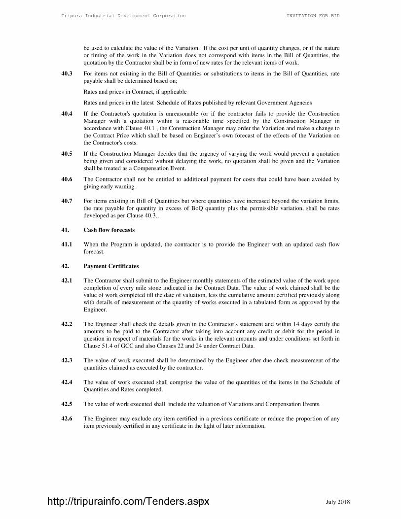
Tripura Industrial Development Corporation INVITATION FOR BID
July 2018 40
be used to calculate the value of the Variation. If the cost per unit of quantity changes, or if the nature
or timing of the work in the Variation does not correspond with items in the Bill of Quantities, the
quotation by the Contractor shall be in form of new rates for the relevant items of work.
40.3 For items not existing in the Bill of Quantities or substitutions to items in the Bill of Quantities, rate
payable shall be determined based on;
Rates and prices in Contract, if applicable
Rates and prices in the latest Schedule of Rates published by relevant Government Agencies
40.4 If the Contractor's quotation is unreasonable (or if the contractor fails to provide the Construction
Manager with a quotation within a reasonable time specified by the Construction Manager in
accordance with Clause 40.1 , the Construction Manager may order the Variation and make a change to
the Contract Price which shall be based on Engineer’s own forecast of the effects of the Variation on
the Contractor's costs.
40.5 If the Construction Manager decides that the urgency of varying the work would prevent a quotation
being given and considered without delaying the work, no quotation shall be given and the Variation
shall be treated as a Compensation Event.
40.6 The Contractor shall not be entitled to additional payment for costs that could have been avoided by
giving early warning.
40.7 For items existing in Bill of Quantities but where quantities have increased beyond the variation limits,
the rate payable for quantity in excess of BoQ quantity plus the permissible variation, shall be rates
developed as per Clause 40.3.,
41. Cash flow forecasts
41.1 When the Program is updated, the contractor is to provide the Engineer with an updated cash flow
forecast.
42. Payment Certificates
42.1 The Contractor shall submit to the Engineer monthly statements of the estimated value of the work upon
completion of every mile stone indicated in the Contract Data. The value of work claimed shall be the
value of work completed till the date of valuation, less the cumulative amount certified previously along
with details of measurement of the quantity of works executed in a tabulated form as approved by the
Engineer.
42.2 The Engineer shall check the details given in the Contractor's statement and within 14 days certify the
amounts to be paid to the Contractor after taking into account any credit or debit for the period in
question in respect of materials for the works in the relevant amounts and under conditions set forth in
Clause 51.4 of GCC and also Clauses 22 and 24 under Contract Data.
42.3 The value of work executed shall be determined by the Engineer after due check measurement of the
quantities claimed as executed by the contractor.
42.4 The value of work executed shall comprise the value of the quantities of the items in the Schedule of
Quantities and Rates completed.
42.5 The value of work executed shall include the valuation of Variations and Compensation Events.
42.6 The Engineer may exclude any item certified in a previous certificate or reduce the proportion of any
item previously certified in any certificate in the light of later information.
http://tripurainfo.com/Tenders.aspx

Tripura Industrial Development Corporation INVITATION FOR BID
July 2018 41
43. Payments
First RA Bill shall be prepared and submitted by the contractor only after completion of 25% of
T Tendered value.
For remaining RA Bills, the Bills shall be prepared and submitted by the contractor for a value of not
less than Rs.100 Lacs. Joint measurement shall be taken continuously and need not be connected to
billing stage. System of five copies of measurement one for contractor, two for engineer, one for
Construction Manager and one for Employer and signed by both contractor and Engineer shall be
followed.
50% of the monthly bill amount will be paid within 15 days of submission of the bill. The balance
amount of the verified bill by the engineer should be paid within 15 days of the submission of bill after
adjustment for deductions for advance payments, retention, other recoveries in terms of the contract
and taxes, at source, as applicable under the law.
For delay in payments, not attributable to the contractor, beyond the periods specified in 43.2 above,
interest at a rate of 12 % per annum should be paid.
Items of the Works for which no rate or price has been entered in will not be paid for by the Employer
and shall be deemed covered by other rates and prices in the Contract.
The contractor shall send to the Engineer once every month an account giving particulars (as full and
detailed as possible) of all claims for any additional expense to which the Contractor may consider
himself entitled. He shall also send to the Engineer a claim list of all extra or additional work ordered in
writing by the Engineer, in the preceding month.
The contractor shall submit final bill within 60 days of issue of completion certificate. Engineer shall
check the bill within 60 days after its receipt and return the bill to contractor for corrections if any. 50%
of undisputed amount shall be paid to the contractor at the stage of returning the bill.
Contractor should resubmit the bill, with corrections within 30 days of its return by the Engineer. The
resubmitted bill shall be checked and paid within 60 days of its receipt.
Interest @ 12 % per annum shall be paid if the bill is not paid within the time limit specified above.
If an amount certified is increase in a later certificate as a result of award by the contractor shall paid the
interest upon delayed payment as set out in this clause. Interest shall be calculated @ 12% per annum
from the date upon which the increase amount would have been certified in the absence of dispute.
44. Compensation Events
44.1 The following are Compensation Events unless they are caused by the Contractor:
(a) The Employer does not give access to a part of the Site by the Site Possession Date stated in the
Contract Data.
(b) The Employer modifies the schedule of other contractors in a way which affects the work of the
contractor under the contract.
(c) The Engineer orders a delay or does not issue drawings, specifications or instructions required
for execution of works on time.
(d) The Engineer instructs the Contractor to uncover or to carry out additional tests upon work
which is then found to have no Defects.
(e) Ground conditions are substantially more adverse than could reasonably have been assumed
before issuance of Letter of Acceptance from the information issued to Bidders (including the
Site Investigation Reports), from information available publicly and from a visual inspection of
the Site.
(f) The Engineer gives an instruction for dealing with an unforeseen condition, caused by the
Employer, or additional work required for safety or other reasons.
http://tripurainfo.com/Tenders.aspx

Tripura Industrial Development Corporation INVITATION FOR BID
July 2018 42
(g) Other contractors, public authorities, utilities or the Employer does not work within the dates and
other constraints stated in the Contract, and they cause delay or extra cost to the Contractor.
(h) The advance payment is delayed.
(i) The effect on the Contractor of any of the Employer’s Risks.
(j) The Engineer unreasonably delays in issuing a Certificate of Completion.
(k) Other Compensation Events listed in the Contract Data or mentioned in the Contract.
44.2 If a Compensation Event would cause additional cost or would prevent the work being completed
before the Intended Completion Date, the Contract Price shall be increased and/or the Intended
Completion Date is extended. The Construction Manager shall decide whether and by how much the
Contract Price shall be increased and whether and by how much the Intended Completion Date shall be
extended.
44.3 As soon as information demonstrating the effect of each Compensation Event upon the Contractor's
forecast cost has been provided by the Contractor, it is to be assessed by the Engineer / Construction
Manager and the Contract Price shall be adjusted accordingly. If the Contractor's forecast is deemed
unreasonable, the Construction Manager shall adjust the Contract Price based on Engineer’s own
forecast. The Engineer / Construction Manager will assume that the Contractor will react competently
and promptly to the event.
44.4 The Contractor shall not be entitled to compensation to the extent that the Employer's interests are
adversely affected by the Contractor not having given early warning or not having cooperated with the
Engineer.
45. Tax
45.1 The rates quoted by the Contractor shall be deemed to be inclusive of all taxes, levies and expenses that
the Contractor will have to pay for the performance of this Contract. The Employer will perform such
duties in regard to the deduction of such taxes at source as per applicable law.
46. Currencies
46.1 All payments shall be made in Indian Rupees.
47. Not Used
48. Retention
48.1 The Employer shall retain from each payment due to the Contractor the proportion stated in the
Contract Data until Completion of the whole of the Works.
48.2 Retention money shall be refunded within 60 days after issue of Completion Certificate.
49. Liquidated Damages
49.1 If the Contract period is extended due to the omissions and/or commissions of Contractor, the cost of
supervision for the extended period shall be borne by the Contractor. This payment shall be paid
monthly and shall be equal to the full fee for Supervision of the Construction Manager divided the
number of months in the contract Period. This money will be deducted from any monies due to the
Contractor, by way of periodical payment or otherwise.
http://tripurainfo.com/Tenders.aspx

Tripura Industrial Development Corporation INVITATION FOR BID
July 2018 43
49.2 If the Contractor fails to complete the work under contract within the stipulated completion date, he
shall pay liquidated damages to the Employer at the rate stated in the Contract Data for each week or
part that the Completion Date is later than the Intended Completion Date (for the whole of the works or
the milestone as stated in the contract data. Even if , a part of the work is completed, if it cannot be put
into operation because of the non completion of the remaining works, the liquidated damages shall be
calculated on the full value of the contract. The total amount of liquidated damages shall not exceed the
amount defined in the Contract Data. The Employer may deduct liquidated damages from payments due
to the Contractor. Payment of liquidated damages does not affect the Contractor's liabilities.
49.3 If the Intended Completion Date is extended after liquidated damages have been paid, the Engineer
shall correct any overpayment of liquidated damages by the Contractor by adjusting the next payment
certificate. interest shall not be paid on such overpayments.
49.4 Delays requiring payment of full liquidated damages shall be sufficient clause for termination of
contract and forfeiture of security deposit against performance bond ( performance guarantee)
49.5 “Time is the essence of the contract and payment or deduction of liquidated damages shall not relieve the
contractor from his obligation to complete the work as per agreed construction program and milestones
or from any other of the contractor’s obligations and liabilities under the contract.”
50. Bonus
50.1 For early completion of contract before the stipulated date of completion or such later date as
authorized by the Employer, incentive shall be paid to the Contractor at 0.5% of the Contract price per
week of early completion, subject to a maximum of 5% of contract price. This incentive shall be
applicable in cases where completion of work before scheduled dates lead to tangible benefits.
51. Advance Payment
51.1 The Employer shall make advance payment to the Contractor of the amounts stated in the Contract Data
by the date stated in the Contract Data, against provision by the Contractor of an Unconditional Bank
Guarantee in a form and by a bank acceptable to the Employer in amounts and currencies equal to the
advance payment. The guarantee shall remain effective until the intended date of completion, but the
amount of the guarantee shall be progressively reduced by the amounts repaid by the Contractor.
51.2 The Contractor is to use the advance payment only to pay for Equipment, Plant and Mobilization
expenses required specifically for execution of the Works. The Contractor shall demonstrate that
advance payment has been used in this way by supplying copies of invoices or other relevant documents
to the Engineer.
51.3 The advance payment shall be recovered by deducting proportionate amounts from payments otherwise
due to the Contractor, following the schedule of completed percentages of the Works on a payment
basis. No account shall be taken of the advance (mobilization and equipment only) payment or its
repayment in assessing valuations of work done, Variations, price adjustments, Compensation Events,
or Liquidated Damages.
51.4 Not Use
52. Performance Security
52.1 The Performance Security shall be provided to the Employer no later than the date specified in the
Letter of Acceptance and shall be issued in an amount and form and by a bank or surety acceptable to
the Employer, and denominated in Indian Rupees. The Performance Security shall be valid until a date
28 days from the date of expiry of Defects Liability Period and the additional security for unbalanced
bids shall be valid until a date 28 days from the date of issue of the certificate of completion
http://tripurainfo.com/Tenders.aspx

Tripura Industrial Development Corporation INVITATION FOR BID
July 2018 44
53. Day works
Any work shall be executed on a Day work basis only if the Engineer instructs the same in writing. The
Instruction from the Engineer shall clearly state the nature and volume of work, the expected personnel
to be employed and the period for completion. The Instruction so issued shall be accepted by the
Contractor , subject to revision on completion of the work. Upon completion of the work, The
Contractor shall submit a statement indicating the names, occupation of the personnel worked, the
number of equipment used and the quantity of the materials used. The payment for the work shall be
made on the basis of the day works rate quoted by the contractor.
54. Defect Liability and Cost of Repairs
54.1 Loss or damage to the Works or Materials to be incorporated in the Works between the Date of
Commencement and the end of the Defects Correction periods shall be remedied by the Contractor at
the Contractor's cost if the loss or damage arises from the Contractor's acts or omissions. The
Contractor shall be responsible to make good at his own expense any defect which may develop within
the period mentioned as defect liability period in the Contract Data. The Employer shall give the
Contractor a notice in writing about the defects and the Contractor shall repair the defect in maximum
of 7 days. If the contractor fails to repair/remove the defect, the Employer may execute the work by
himself and deduct the expense towards the work from any monies due to the Contractor. The employer
shall have the right to appropriate all or part of the security deposit towards the expense in repairing
the defects.
E. Finishing the Contract
55. Completion
55.1 After completion of the work, the contractor will serve a written notice to the Construction Manager to
this effect. The Construction Manager upon receipt of this notice shall conduct a complete joint survey
of the work within 7 days and prepare a defects list jointly. The defects pointed out by the Construction
Manager or his nominee would be rectified by the contractor within 14 days and thereafter acceptance
report be signed jointly by the contractor, Construction Manager and the Employer. This joint
acceptance report shall be treated as ‘Completion Certificate’.
56. Taking Over
56.1 The Employer shall take over the Site and the Works within seven days of the Construction Manager
issuing a certificate of Completion.
57. Deleted
58. As Built Drawings
58.1 The Contractor shall supply “As Built” Drawings by the dates stated in the Contract Data.
58.2 If the Contractor does not supply the Drawings by the dates stated in the Contract Data, or they do not
receive the Engineer’s approval, the Engineer shall withhold the amount stated in the Contract Data
from payments due to the Contractor.
59. Termination
59.1 The Employer or the Contractor may terminate the Contract if the other party causes a fundamental
breach of the Contract.
59.2 Fundamental breaches of Contract include, but shall not be limited to the following:
(a) the Contractor stops work for 28 days when no stoppage of work is shown on the current program
and the stoppage has not been authorized by the Engineer;
http://tripurainfo.com/Tenders.aspx

Tripura Industrial Development Corporation INVITATION FOR BID
July 2018 45
(b) the Engineer / Construction Manager instructs the Contractor to delay the progress of the Works
and the instruction is not withdrawn within 28 days;
(c) the Employer or the Contractor is made bankrupt or goes into liquidation other than for a
reconstruction or amalgamation;
(d) a payment certified by the Engineer / Construction Manager is not paid by the Employer to the
Contractor within 56 days of the date of the Engineer's certificate;
(e) the Engineer / Construction Manager gives Notice that failure to correct a particular Defect is a
fundamental breach of Contract and the Contractor fails to correct it within a reasonable period of
time determined by the Engineer;
(f) the Contractor does not maintain a security which is required;
(g) the Contractor has delayed the completion of works by the number of days for which the maximum
amount of liquidated damages can be paid as defined in the Contract data; and
(h) if the Contractor, in the judgment of the Employer has engaged in fraud and corruption, as defined
in ITB Clause 35.1, in competing for or in executing the Contract.
(i) in case the Contractor has awarded more than 20 % of value of works on sub contract (excluding
works awarded to nominated contractor).
(j) the contractor has defaulted in fulfilling his obligations under this contract.
59.3 When either party to the Contract gives notice of a breach of contract to the Engineer / Construction
Manager for a cause other than those listed under Sub Clause 59.2 above, the Engineer / Construction
Manager shall decide whether the breach is fundamental or not.
59.4 Notwithstanding the above, the Employer may terminate the Contract for convenience.
59.5 If the Contract is terminated the Contractor shall stop work immediately, make the Site safe and secure
and leave the Site as soon as reasonably possible.
60. Payment upon Termination
60.1 If the Contract is terminated because of a fundamental breach of Contract by the Contractor, the
Engineer / Construction Manager shall issue a certificate for the value of the work done less advance
payments received up to the date of the issue of the certificate, less other recoveries due in terms of the
contract, less taxes due to be deducted at source as per applicable law and less the percentage to apply
to the work not completed as indicated in the Contract Data. Additional Liquidated Damages shall not
apply . If the total amount due to the Employer exceeds any payment due to the Contractor the
difference shall be a debt payable to the Employer.
60.2 If the Contract is terminated at the Employer's convenience or because of a fundamental breach of
Contract by the Employer, the Engineer / Construction Manager shall issue a certificate for the value of
the work done, the reasonable cost of removal of Equipment, repatriation of the Contractor's personnel
employed solely on the Works, and the Contractor's costs of protecting and securing the Works and less
advance payments received up to the date of the certificate, less other recoveries due in terms of the
contract and less taxes due to be deducted at source as per applicable law.
61. Property
61.1 All materials on the Site, Plant, Equipment, Temporary Works and Works are deemed to be the
property of the Employer, if the Contract is terminated because of a Contractor’s default.
http://tripurainfo.com/Tenders.aspx

Tripura Industrial Development Corporation INVITATION FOR BID
July 2018 46
62. Release from Performance
62.1 If the Contract is frustrated by the outbreak of war or by any other event entirely outside the control of
either the Employer or the Contractor the Construction Manager shall certify that the Contract has been
frustrated. The Contractor shall make the Site safe and stop work as quickly as possible after receiving
this certificate and shall be paid for all work carried out before receiving it and for any work carried out
afterwards to which commitment was made.
Special Conditions of Contract
1. General
The Contractor is advised to note that the following Special Conditions are part of the Contract and he
will not have any right to claim at any time for delays or for expenditure incurred by him in fulfilling
the following special conditions.
2. Scope of Works
The scope of work includes Construction of civil works for LCS Muhurighat, Belonia with internal and
external plumbing works, electrical works, fire alarm system, PA system and landscaping works .
3. Tender Drawings
The drawings issued with these Tender Documents are Tender Drawings. Tender Drawings are
prepared in such detail as are necessary to give a comprehensive idea of the works. The good for
construction drawings will be issued during the construction stage based on the requirements as per the
construction program submitted by the contractor as per GCC clause 27.
4. Working Drawings
The Contract Drawings shall be supplemented by working drawings or shop drawings prepared by the
Contractor which are required for the execution of the works. These working drawings shall include all
details required for execution of job and any other detail the Engineer may ask during construction.
All drawings shall be computerized and shall be submitted both in hard copy as well as digital data.
Approval by the Engineer of the Contractor’s working drawings shall not relieve the Contractor from
responsibility for the accuracy of dimensions and details, nor shall such mutual agreement and
compliance to his working drawings constitute an acceptance by the Employer of the correctness and
adequacy of the drawings.
Working drawings as required or as directed by the Engineer shall be prepared and submitted by the
Contractor sufficiently in advance. All working drawings shall be checked by the Engineer /
Construction Manager and work can commence only upon getting approval of the working drawing.
Delays to work by reason of lack of approvals of working drawings and shop drawings are deemed to
be a risk the Contractor is taking with full knowledge and no compensation shall be claimed by the
Contractor or none given by the Employer, on account of such delay.
The costs of furnishing working drawings shall be included in the rates for various paying items given
in the Bill of Quantities.
In this respect the Contractor shall employ his Engineers and AutoCAD Draughtsman specifically for
planning and preparation of working drawings. The Contractor shall also provide as part of the
mobilization to site, a latest Computer and software together with new colour printer, for the
preparation of his working Drawings. The Engineer shall have access to this Computer.
http://tripurainfo.com/Tenders.aspx

Tripura Industrial Development Corporation INVITATION FOR BID
July 2018 47
5. Additional Work
Any additional works, instructed during the Contract Period and within the Contract Amount, will be
paid as per Bill of Quantity rates and it shall not be considered as a cause for the Contractor to claim for
delay, incurred overhead, mobilization etc.
6. Protection of the Works during Contract Period
It is clearly understood that any damage occurring to the Works (completed or under execution) is the
Contractors responsibility and no claims will be entertained by the Employer since the matter shall be
covered by the relevant Insurances.
7. Discrepancies in alignment
Discrepancies in alignment and levels etc., noticed during construction and/or on completion shall be
rectified by the Contractor at his own cost, Engineer’s approval does not relieve the Contractor of his
responsibilities.
8. Temporary Power and Water Supply
All costs, both for power supply and temporary installations and Power and Water required for
construction and labour shall be borne by the Contractor.
9. Contractor’s Facilities
9.1 Site Offices of the Contractor
The successful Tenderer is to provide and maintain a site office at a location approved by the Engineer /
Construction Manager in consultation with the Employer, within 15 days from the date of issue of
Notice to Proceed. A separate Engineers office of about 50 Sqm shall be provided. This Engineers
office shall be of standard quality and furnished. The maintenance of this Engineers office is also the
responsibility of contractor.
9.2 Surveying Equipment
The Contractor shall provide, at his own expense one approved set of surveying and measuring
equipment at the site for the sole use of the Surveyors of the Project. It shall also be made available for
the Engineer / Construction Manager upon request. The set shall consist of (i) One Total
Station/Theodolite, (ii) One pogo with reflector, (iii) One big tripod (iv) One small tripod (v) Two
fiber glass tape (cased 30 m ) (vi) Four steel pocket tape 3 m long (vii) Two surveying umbrellas (viii)
Ten ranging rods 2.5 m long (ix) Required numbers of level books and field books.
All accessories and assistance required for setting out, measuring etc. shall be supplied as and when
required by the Engineer or his representative.
The contractor shall be solely responsible for the maintenance of all such instruments and equipments
and shall ensure that they are at all times in good condition.
All the surveying equipments shall remain the property of the Contractor till the end of the Contract.
The Contractor is obliged to replace any instrument or part thereof damaged during the Contract Period.
9.3 Laboratory and Laboratory Testing
The Contractor shall provide at site and maintain during the entire contract period a Laboratory for
testing of concrete or alternatively make arrangements for getting the concrete cubes made at site, tested
in an approved laboratory away from the site. If in case the Contractor opts for making alternative
arrangements, then the laboratory proposed should be got inspected and approved by the Engineer
within 30 days of commencement of work.
http://tripurainfo.com/Tenders.aspx

Tripura Industrial Development Corporation INVITATION FOR BID
July 2018 48
10. Notice Boards
Two Notice Boards shall be provided and erected as directed by the Engineer. The boards shall be
maintained and repainted if directed by the Engineer till the final handing over of project.
The Contractor shall submit for approval of the Employer and Engineer working drawing showing all
details needed in the board and the location of the board. Cost of providing and installing the notice
board is deemed to be included in various items of the Bill of Quantities.
11. Progress Photographs and Reports
Contractor shall submit monthly 12 progress Photographs 12” x 8” size in five copies as part of his
monthly progress report, as specified in the Special Specifications..
At the end of the Project the Contractor shall deliver to the Engineer two albums having the most
significant Photographs taken during the Contract Period. Each Album shall have a minimum of 20
photographs of 12”x8” Size.
12. Safety on Site
Measures to ensure safety of workers and plant at site shall be taken by the Contractor. Excavations
shall be protected by barriers and lighting shall be provided at night to warn pedestrians and vehicles.
Motorable access to the site and within the site shall be maintained during the construction period. The
Contractor shall designate a Safety Officer who will be in charge of all Safety Measures. The cost of all
safety equipments and the cost of providing a safety officer at site would be deemed to be included in
various Items of the Schedule of Quantities and Rates. The contractor will prepare a safety manual and
submit for Engineer’s approval before the commencement of work.
13. As Built Drawings
The Contractor shall prepare As Built Drawings both in hard copy and in digital format.
The drawings shall be prepared for any given section of the work as soon as the work for that particular
section is completed. Preparation of As Built Drawings shall keep pace with the work and shall not be
left over towards the end of the project. 3 hard copies and one soft copy of all drawings shall be
submitted.
No separate payment will be made for the preparation of As-Built Drawings; Cost of preparation of As
Built Drawing is deemed to be included in all other priced bill items.
14. Labour
The Contractor shall, unless otherwise provided in the Contract, make his own arrangements for the
engagement of all staff and labour, local or other, and for their payment, housing, feeding and transport.
The Contractor shall, if required by the Engineer, deliver to the Engineer a return in detail, in such form
and at such intervals as the Engineer may prescribe, showing the staff and the numbers of the several
classes of labour from time to time employed by the Contractor on the Site and such other information
as the Engineer may require.
14.1 Compliance with Labour Regulations
During continuance of the contract, the Contractor and his sub contractors shall abide at all times by all
existing labour enactments and rules made there under, regulations, notifications and bye laws of the
State or Central Government or local authority and any other labour law (including rules), regulations,
bye laws that may be passed or notification that may be issued under any labour law in future either by
the State or the Central Government or the local authority. Salient features of some of the major labour
laws that are applicable to construction industry are given below. The Contractor shall keep the
Employer indemnified in case any action is taken against the Employer by the competent authority on
http://tripurainfo.com/Tenders.aspx

Tripura Industrial Development Corporation INVITATION FOR BID
July 2018 49
account of contravention of any of the provisions of any Act or rules made there under, regulations or
notifications including amendments. If the Employer is caused to pay or reimburse, such amounts as
may be necessary to cause or observe, or for non-observance of the provisions stipulated in the
notifications/bye laws/Acts/Rules/regulations including amendments, if any, on the part of the
Contractor, the Engineer/Employer shall have the right to deduct any money due to the Contractor
including his amount of performance security. The Employer/Engineer / Construction Manager shall
also have right to recover from the Contractor any sum required or estimated to be required for making
good the loss or damage suffered by the Employer.
The employees of the Contractor and the Sub-Contractor in no case shall be treated as the employees of
the Employer at any point of time.
SALIENT FEATURES OF SOME MAJOR LABOUR LAWS APPLICABLE TO
ESTABLISHMENTS ENGAGED IN BUILDING AND OTHER CONSTRUCTION WORK
(The law as current on the date of bid opening will apply)
a) Workmen Compensation Act 1923: The Act provides for compensation in case of injury by
accident arising out of and during the course of employment.
b) Payment of Gratuity Act 1972: Gratuity is payable to an employee under the Act on
satisfaction of certain conditions on separation if an employee has completed 5 years service
or more or on death the rate of 15 days wages for every completed year of service. The Act is
applicable to all establishments employing 10 or more employees.
c) Employees P.F. and Miscellaneous Provision Act 1952 (since amended): The Act Provides for
monthly contributions by the Employer plus workers @ 10% or 8.33%. The benefits payable
under the Act are :
(i) Pension or family pension on retirement or death, as the case may be.
(ii) Deposit linked insurance on the death in harness of the worker.
(iii) payment of P.F. accumulation on retirement/death etc.
d) Maternity Benefit Act 1951: The Act provides for leave and some other benefits to women
employees in case of confinement or miscarriage etc.
e) Contract Labour (Regulation & Abolition) Act 1970: The Act provides for certain welfare
measures to be provided by the Contractor to contract labour and in case the Contractor fails to
provide, the same are required to be provided, by the Principal Employer by Law. The
Principal Employer is required to take Certificate of Registration and the Contractor is
required to take license from the designated Officer. The Act is applicable to the
establishments or Contractor of Principal Employer if they employ 20 or more contract labour.
f) Minimum Wages Act 1948: The Employer is supposed to pay not less than the Minimum
Wages fixed by appropriate Government as per provisions of the Act if the employment is a
scheduled employment. Construction of Buildings, Roads, Runways are scheduled
employments.
g) Payment of Wages Act 1936: It lays down as to by what date the wages are to be paid, when
it will be paid and what deductions can be made from the wages of the workers.
h) Equal Remuneration Act 1979: The Act provides for payment of equal wages for work of
equal nature to Male and Female workers and for not making discrimination against Female
employees in the matters of transfers, training and promotions etc.
i) Payment of Bonus Act 1965: The Act is applicable to all establishments employing 20 or
more employees. The Act provides for payments of annual bonus subject to a minimum of
8.33% of wages and maximum of 20% of wages to employees drawing Rs.3500/-per month or
http://tripurainfo.com/Tenders.aspx
Tripura Industrial Development Corporation INVITATION FOR BID
July 2018 50
less. The bonus to be paid to employees getting Rs.2500/- per month or above upto Rs.3500/-
per month shall be worked out by taking wages as Rs.2500/-per month only. The Act does not
apply to certain establishments. The newly set-up establishments are exempted for five years in
certain circumstances. Some of the State Governments have reduced the employment size from
20 to 10 for the purpose of applicability of this Act.
j) Industrial Disputes Act 1947: The Act lays down the machinery and procedure for resolution
of Industrial disputes, in what situations a strike or lock-out becomes illegal and what are the
requirements for laying off or retrenching the employees or closing down the establishment.
k) Industrial Employment (Standing Orders) Act 1946: It is applicable to all establishments
employing 100 or more workmen (employment size reduced by some of the States and Central
Government to 50). The Act provides for laying down rules governing the conditions of
employment by the Employer on matters provided in the Act and get the same certified by the
designated Authority.
l) Trade Unions Act 1926: The Act lays down the procedure for registration of trade unions of
workmen and employers. The Trade Unions registered under the Act have been given certain
immunities from civil and criminal liabilities.
m) Child Labour (Prohibition & Regulation) Act 1986: The Act prohibits employment of
children below 14 years of age in certain occupations and processes and provides for
regulation of employment of children in all other occupations and processes. Employment of
Child Labour is prohibited in Building and Construction Industry.
n) Inter-State Migrant workmen’s (Regulation of Employment & Conditions of Service) Act
1979: The Act is applicable to an establishment which employs 5 or more inter-state migrant
workmen through an intermediary (who has recruited workmen in one state for employment in
the establishment situated in another state). The Inter-State migrant workmen, in an
establishment to which this Act becomes applicable, are required to be provided certain
facilities such as housing, medical aid, traveling expenses from home upto the establishment
and back, etc.
o) The Building and Other Construction workers (Regulation of Employment and Conditions of
Service) Act 1996 and the Cess Act of 1996: All the establishments who carry on any building
or other construction work and employs 10 or more workers are covered under this Act. All
such establishments are required to pay cess at the rate not exceeding 2% of the cost of
construction as may be modified by the Government. The Employer of the establishment is
required to provide safety measures at the Building or construction work and other welfare
measures, such as Canteens, First-Aid facilities, Ambulance, Housing accommodations for
workers near the work place etc. The Employer to whom the Act applies has to obtain a
registration certificate from the Registering Officer appointed by the Government.
p) Factories Act 1948: The Act lays down the procedure for approval at plans before setting up a
factory, health and safety provisions, welfare provisions, working hours, annual earned leave
and rendering information regarding accidents or dangerous occurrences to designated
authorities. It is applicable to premises employing 10 persons or more with aid of power or 20
or more persons without the aid of power engaged in manufacturing process.
http://tripurainfo.com/Tenders.aspx
Tripura Industrial Development Corporation INVITATION FOR BID
July 2018 51
15. PROTECTION OF ENVIRONMENT:
The contractor shall take all reasonable steps to protect the environment on and off the Site and to avoid
damage or nuisance to persons or to property of the public or others resulting from pollution, noise or
other causes arising as a consequence of his methods of operation. The contractor shall be responsible
for taking necessary clearances and statutory approval from the respective departments for works such
as and not restricted to disposal of debris, procurement of earth for filling etc., outside the site.
During continuance of the contract, the contractor and his sub-contractors shall abide at all times by all
existing enactments on environmental protection and rules made there under, regulations, notifications
and bye-laws of the State or Central Government, or local authorities and any other law, bye-law,
regulations that may be passed or notification that may be issued in this respect in future by the State or
Central Government or the local authority.
Salient features of some of the major laws that are applicable are given below :
The Water (Prevention and Control of Pollution) Act, 1974, This provides for the prevention and
control of water pollution and the maintaining and restoring of wholesomeness of water. 'Pollution'
means such contamination of water or such alteration of the physical, chemical or biological properties
of water or such discharge of any sewage or trade effluent or of any other liquid, gaseous or solid
substance into water (whether directly or indirectly) as may, or is likely to, create a nuisance or render
such water harmful or injurious to public health or safety, or to domestic, commercial, industrial,
agricultural or other legitimate uses, or to the life and health of animals or plants or of aquatic
organisms.
The Air (Prevention and Control of Pollution) Act, 1981, This provides for prevention, control and
abatement of air pollution. 'Air Pollution' means the presence in the atmosphere of any 'air pollutant',
which means any solid, liquid or gaseous substance (including noise) present in the atmosphere in such
concentration as may be or tend to be injurious to human beings or other living creatures or plants or
property or environment.
The Environment (Protection) Act, 1986, This provides for the protection and improvement of
environment and for matters connected therewith, and the prevention of hazards to human beings, other
living creatures, plants and property. 'Environment' includes water, air and land and the inter-
relationship which exists among and between water, air and land, and human beings, other living
creatures, plants, micro-organism and property.
The Public Liability Insurance Act, 1991, This provides for public liability insurance for the purpose of
providing immediate relief to the persons affected by accident occurring while handling hazardous
substances and for matters connected herewith or incidental thereto. Hazardous substance means any
substance or preparation which is defined as hazardous substance under the Environment (Protection)
Act 1986, and exceeding such quantity as may be specified by notification by the Central Government.
http://tripurainfo.com/Tenders.aspx

Tripura Industrial Development Corporation INVITATION FOR BID
July 2018 52
SECTION 4: CONTRACT DATA
http://tripurainfo.com/Tenders.aspx

Tripura Industrial Development Corporation INVITATION FOR BID
July 2018 53
Contract Data
Items marked "N/A" do not apply in this Contract.
1. The following documents are also part of the Contract: Clause
Reference
· The Schedule of Operating and Maintenance Manuals [58]
N/A
· The Schedule of Other Contractors working simultaneously in the area [8]
· The Schedule of Key Personnel ornogram to be submitted along with Bio data of Key
personnel for approval of Engineer [9]
· The Methodology and Program of Construction [27]
· The Schedule of Key and Critical equipment to be deployed [27]
on the work as per agreed program of construction
· Site Investigation reports issued at the Tender Stage [14]
2. The Employer is
Name: The Managing Director
Tripura Industrial Development Corporation (TIDC)
Shilpa Nigam Bhawan,
Khejurbagan,
P.O Kunjaban, Agartala,
Tripura - 799006
Name of authorized Representative: Executive Engineer
3. The Construction Manager/ Engineer is IL&FS, Cluster Development Initiative Ltd,
Dasgupta Villa,
1st Floor, North Side of Governor’s house,
Vill & PO-Kunjaban, Agartala – 799006
Phone: +91 0381-2300419
Name of Authorized Representative : Mr. Shantanu Roy
4. The Engineer’s / Construction Manager’s Representative: will be intimated later (1.1)
Name: Address:
Name of Authorised Representative:
5. The Name and identification number of the Contract is : Setting up of Land Custom Station at Muhurighat,
Belonia, Tripura
6. The Works consist of Construction of Construction of Civil Works for Land Custom Station and
landscaping works (1.1)
7. The Date of Commencement shall be the date specified in the Notice to Proceed with the work. (1.1)
8. The Intended Completion Date for the whole of the Works is 24 months including monsoon
period reckoned from the date of commencement as indicated in the Notice to Proceed,
http://tripurainfo.com/Tenders.aspx

Tripura Industrial Development Corporation INVITATION FOR BID
July 2018 54
issued by the Employer. The work shall have the following milestones (17,28)
9. Milestone :
Physical completion of works Period from the date of commencement of work
Milestone 1- Completion of All Civil Works, Plumbing Works, 24 Months
Electrical work, Fire Alarm System
PA system and Landscaping works etc., Complete
all the works
10. The Contractor shall revise the work Schedule submitted along with the Tender, to include the
commencement date, to reflect the ground realities and adhering to the schedule of milestone indicated
above. This revised work schedule shall be submitted within 14 days of delivery of the Letter of
Acceptance.
11. The Site Possession Date shall be the date within seven days from the date of issue of Notice to proceed
with the work.
12. The site is located at Belonia , South district in the state of Tripura.
13. The Defects Liability Period is 12 month from the date of certification of completion of works. (where
sectional completion certificate is issued this will apply from those dates for those sections). [35]
14. Insurance requirements are as under: [13]
Sr.
No.
Policy for Insurance cover required
1 All risk insurance for
works
By Contractor
2 Loss or damage to
Employer’s Equipment
By Contractor
3 Other Employers property By Contractor
4 Personal injury or death
insurance:
a) Third party
By Contractor
b) For Contractor’s
Employee
By Contractor
Contractor should ensure such insurance is in force through out the
contract period (Including defect liability period) and necessary
proof to be submitted before the commencement of the project and at
least a fortnight before the expiry of current insurance.
The contractor should indemnify and include in the policy the
employer , Construction manager and engineer
(iii) Motor Vehicle Insurance By Contractor as per statutory requirements, covering third party
liability.
Third party liability
insurance (Including the
name of Employer)
By contractor
Minimum cover Rs. 1Million
Contractor’s Equipments
(Including liability arising
out of usages of such
equipment)
By Contractor.
15. The period between Program updates shall be 30 days. A penalty of Rs. 500 per week
will be levied for default. [27]
16. The language of the Contract documents is English [3]
17. The law which applies to the Contract is the laws of Union of India [3]
http://tripurainfo.com/Tenders.aspx

Tripura Industrial Development Corporation INVITATION FOR BID
July 2018 55
18. The currency of the Contract is Indian Rupees. [46]
19. The proportion of payments retained (retention money) shall be 5 % from each bill
to be released within 60 days after the issue of Completion Certificates. [48]
20. The liquidated damages for the whole of the works are 0.5% of the contract value per week or part [49]
21. The maximum amount of liquidated damages for the whole of the works is five percent of final [49]
contract price.
22. The amounts of the advance payment are: [51]
Nature of Advance Amount (Rs.) Conditions to be fulfilled
1. Mobilization 10% of the Contract price On submission of un-conditional Bank Guarantee.
(to be drawn before end of 20% of Contract period)
10 % of the contract value.
(The advance payment will be paid to the Contractor no later than 15 days after fulfillment of
the above conditions).
23. Repayment of advance payment for mobilization and equipment: [51]
The advance shall be recovered with percentage deductions from the interim payments
certified by the Engineer under the Contract. The mobilization advance recovery will
start on reaching 20% of contract price and recovered fully by completion of 80% of
contract price on pro rata basis. The advance shall be completely recovered prior to the
expiry of the original time for completion.
24. Deleted
25. The Securities shall be for the following minimum amounts equivalent as a percentage of [52]
the Contract Price:
Performance Security shall be for 5% per cent of contract price to be submitted prior to
signing the Contract. Performance Security shall be released within 30 days after the
Completion of the defect liability period
The standard form of Performance Security acceptable to the Employer shall be an
unconditional and irrevocable Bank Guarantee of the type as presented in Section 5 of
the
Bidding Documents and valid for one month after the expiry of the defect liability
period.
26. Deleted [58]
27. The date by which “as-built” drawings (in scale 1 IN 2000) in 2 sets are required is before
issue of certificate of completion of whole or section of the work, as the case may be.
The amount to be withheld for non submission is Rs. 10, 00, 000/-. [58]
28. The following events shall also be fundamental breach of contract: [59.2]
The Contractor has contravened any clause / sub-clause of the GCC.
1. The contractor does not adhere to the agreed construction program and agreed
environmental management plan (Clause 27 of GCC) and also fails to take
satisfactory remedial action as per agreements reached in the management
meetings (Clause 31) for a period of 60 days.
http://tripurainfo.com/Tenders.aspx

Tripura Industrial Development Corporation INVITATION FOR BID
July 2018 56
2. The contractor fails to carry out the instructions of Engineer / Construction
Manager within a reasonable time determined by the Engineer / Construction
Manager in accordance with GCC Clause 16.1 and 23.1.
3. The percentage to be applied for the value of work not completed representing the
Employer's additional cost for completing the Works shall be 20%. (60.1)
http://tripurainfo.com/Tenders.aspx

Tripura Industrial Development Corporation INVITATION FOR BID
July 2018 57
SECTION 5: FORMS OF SECURITIES
http://tripurainfo.com/Tenders.aspx

Tripura Industrial Development Corporation INVITATION FOR BID
July 2018 58
Forms of Securities
Acceptable forms of securities are annexed. Bidders should not complete the Performance and Advance Payment
Security forms at this time. Only the successful Bidder will be required to provide Performance and Advance
Payment Securities in accordance with one of the forms, or in a similar form acceptable to the Employer.
Annex A: Bid Security (Bank Guarantee)
Annex B: Performance Bank Guarantee
Annex B1: Performance Bank Guarantee for Unbalanced Items
Annex C: Bank Guarantee for Advance Payment
http://tripurainfo.com/Tenders.aspx

Tripura Industrial Development Corporation INVITATION FOR BID
July 2018 59
Annex A
BID SECURITY (BANK GUARANTEE)
WHEREAS, _______________________ [name of Bidder] (hereinafter called "the Bidder") has submitted his Bid
dated _______________________ [date] for the (insert the name of the works) (hereinafter called "the Bid").
KNOW ALL PEOPLE by these presents that We ______________________________ [name of bank] of having
our registered office at ___________________________________ (hereinafter called "the Bank") are bound unto
__________________________________________________________________________(hereinafter called "the
Employer") in the sum of Rs.___________________1(Rupees ______________________ _________________
____ ________________________________) for which payment well and truly to be made to the said Employer
the Bank binds itself, his successors and assigns by these presents.
SEALED with the Common Seal of the said Bank this _________ day of __________ 2018.
THE CONDITIONS of this obligation are:
(1) If after Bid opening the Bidder withdraws his bid during the period of Bid validity specified in
the Form of Bid;
or
(2) If the Bidder having been notified of the acceptance of his bid by the Employer during the
period of Bid validity:
(a) fails or refuses to execute the Form of Agreement in accordance with the Instructions
to Bidders, if required; or
(b) fails or refuses to furnish the Performance Security, in accordance with the
Instruction to Bidders; or
(c) does not accept the correction of the Bid Price pursuant to Clause 27;
we undertake to pay to the Employer up to the above amount upon receipt of his first written demand, without any
protest or demur or any objection, whatsoever on our part and without any first claim or reference to the Contractor,
without the Employer having to substantiate his demand, provided that in his demand the Employer will note that the
amount claimed by him is due to him owing to the occurrence of one or any of the three conditions, specifying the
occurred condition or conditions.
This Guarantee will remain in force up to and including the date ____________________2 days after the deadline
for submission of Bids as such deadline is stated in the Instructions to Bidders or as it may be extended by the
Employer, notice of which extension(s) to the Bank is hereby waived. Any demand in respect of this guarantee
should reach the Bank not later than the above date.
DATE _______________ SIGNATURE OF THE BANK _________________________
WITNESS ____________ SEAL _______________________________________
_________________________________________________________________
[signature, name, and address]
1 The Bidder should insert the amount of the guarantee in words and figures denominated in Indian Rupees.
This figure should be the same as shown in Clause 16.1 of the Instructions to Bidders.
2 45 days after the end of the validity period of the Bid.
http://tripurainfo.com/Tenders.aspx

Tripura Industrial Development Corporation INVITATION FOR BID
July 2018 60
Annex B
PERFORMANCE BANK GUARANTEE
To:
WHEREAS _______________________________________________ [name and address of Contractor]
(hereinafter called "the Contractor") has undertaken, in pursuance of Contract No. _____________ dated
______2018 to execute ____________________________________________________________ (hereinafter
called "the Contract");
AND WHEREAS it has been stipulated by you in the said Contract that the Contractor shall furnish you
with a Bank Guarantee by a recognized bank for the sum specified therein as security for compliance with his
obligations in accordance with the Contract;
AND WHEREAS we have agreed to give the Contractor such a Bank Guarantee;
NOW THEREFORE we hereby affirm that we are the Guarantor and responsible to you, on behalf of the
Contractor, up to a total of ____________________ [amount of guarantee] 1___________________________ [in
words], such sum being payable in the types and proportions of currencies in which the Contract Price is payable,
and we undertake to pay you, upon your first written demand without any protest or demur or any objection,
whatsoever on our part and without any first claim or reference to the Contractor, and without cavil or argument, any
sum or sums within the limits of ____________________ [amount of guarantee]1 as aforesaid without your needing
to prove or to show grounds or reasons for your demand for the sum specified therein.
We hereby waive the necessity of your demanding the said debt from the Contractor before presenting us
with the demand.
We further agree that no change or addition to or other modification of the terms of the Contract or of the
Works to be performed there under or of any of the Contract documents which may be made between you and the
Contractor shall in any way release us from any liability under this guarantee, and we hereby waive notice of any
such change, addition or modification.
This guarantee shall be valid until _____________(i.e.) 28 days from the date of expiry of the Defects
Liability Period.
Signature and seal of the guarantor _____________________________
Name of Bank ____________________________________________
Address ____________________________________________
Date ____________________________________________
1 An amount shall be inserted by the Guarantor, representing the percentage of the Contract Price specified in
the Contract and denominated in Indian Rupees.
http://tripurainfo.com/Tenders.aspx

Tripura Industrial Development Corporation INVITATION FOR BID
July 2018 61
Annex B 1
PERFORMANCE BANK GUARANTEE (for unbalanced items)
To:
WHEREAS _________________________ [name and address of Contractor] (hereinafter called "the
Contractor") has undertaken, in pursuance of Contract No. dated ________________ to execute
___________________________________________________________(hereinafter called "the Contract");
AND WHEREAS it has been stipulated by you in the said Contract that the Contractor shall furnish you
with a Bank Guarantee by a recognized bank for the sum specified therein as security for compliance with his
obligations in accordance with the Contract;
AND WHEREAS we have agreed to give the Contractor such a Bank Guarantee;
NOW THEREFORE we hereby affirm that we are the Guarantor and responsible to you, on behalf of the
Contractor, up to a total of ____________________ [amount of guarantee] 1___________________________ [in
words], such sum being payable in the types and proportions of currencies in which the Contract Price is payable,
and we undertake to pay you, upon your first written demand without any protest or demur or any objection,
whatsoever on our part and without any first claim or reference to the Contractor, and without cavil or argument, any
sum or sums within the limits of ____________________ [amount of guarantee]1 as aforesaid without your needing
to prove or to show grounds or reasons for your demand for the sum specified therein.
We hereby waive the necessity of your demanding the said debt from the Contractor before presenting us
with the demand.
We further agree that no change or addition to or other modification of the terms of the Contract or of the
Works to be performed there under or of any of the Contract documents which may be made between you and the
Contractor shall in any way release us from any liability under this guarantee, and we hereby waive notice of any
such change, addition or modification.
This guarantee shall be valid until ____________(i.e.) 28 days from the date of issue of the certificate of
completion of works.
Signature and seal of the guarantor _____________________________
Name of Bank ____________________________________________
Address ____________________________________________
Date ____________________________________________
1 An amount shall be inserted by the Guarantor, representing additional security for unbalanced Bids, if any
and denominated in Indian Rupees.
http://tripurainfo.com/Tenders.aspx

Tripura Industrial Development Corporation INVITATION FOR BID
July 2018 62
Annex C
BANK GUARANTEE FOR ADVANCE PAYMENT
To:
Name of Contract:-
Gentlemen:
In accordance with the provisions of the Conditions of Contract, sub clause 51.1 ("Advance Payment") of
the above-mentioned Contract, ________________________________ [name and address of Contractor]
(hereinafter called "the Contractor") shall deposit with ______________________________________________ a
bank guarantee to guarantee his proper and faithful performance under the said Clause of the Contract in an amount
of _____________ [amount of guarantee] 1_________________________________ [in words].
We, the ____________________ [bank or financial institution], as instructed by the Contractor, agree
unconditionally and irrevocably to guarantee as primary obligator and not as Surety merely, the payment to
________________________________________________________on his first demand without whatsoever right
of objection on our part and without his first claim to the Contractor, in the amount not exceeding
____________________ [amount of guarantee]1 __________________________________ [in words].
We further agree that no change or addition to or other modification of the terms of the Contract or of
Works to be performed there under or of any of the Contract documents which may be made between
________________________________________________________________ and the Contractor, shall in any
way release us from any liability under this guarantee, and we hereby waive notice of any such change, addition or
modification.
This guarantee shall remain valid and in full effect from the date of the advance payment under the Contract
until ________________________________________________________________________ receives full
repayment of the same amount from the Contractor.
Yours truly,
Signature and seal: _______________________________
Name of Bank/Financial Institution: _________________
Address: _______________________________________
Date: ____________________
1 An amount shall be inserted by the bank representing the amount of the Advance Payment, and denominated
in Indian Rupees.
http://tripurainfo.com/Tenders.aspx

TRIPURA INDUSTRIAL DEVELOPMENT CORPORATION
Tender for Setting up of Land Custom Station Muhurighat,Belonia,
TIDC/LCS/CIVIL/MUHURIGHAT/01/2018
Technical Specification
Project Management
TRIPURA INDUSTRIAL DEVELOPMENT CORPORATION
Tender for Setting up of Land Custom Station Muhurighat,Belonia,
Tripura
TIDC/LCS/CIVIL/MUHURIGHAT/01/2018-19
BOOK – 2
Technical Specification
Consultants: - July 2018
TRIPURA INDUSTRIAL DEVELOPMENT CORPORATION
Tender for Setting up of Land Custom Station Muhurighat,Belonia,
19
July 2018
http://tripurainfo.com/Tenders.aspx

TECHNICAL SPECIFICATIONS
Section I
Structural and Architectural Works
http://tripurainfo.com/Tenders.aspx

I N D E X
SECTION NO.
DESCRIPTION PAGE NUMBER
FROM TO
I GENERAL SPECIFICATION 3 9
A EARTHWORK FOR FOUNDATIONS
& METAL PACKING
10 13
B CONCRETE – PLAIN & REINFORCED 14 35
C FORM WORK 36 40
D REINFORCEMENT 41 42
E STRUCTURAL STEEL WORK 43 54
F MASONRY WORK 55 60
G PLASTERING & POINTING 61 62
H PAINTING 63 66
J FLOORING & CLADDING 67 74
K CARPENTARY, JOINERY, ALUMINIUM DOORS,
WINDOWS AND SKY LIGHT
75 88
L LANDSCAPING WORKS 89 96
M WATERPROOFING 97 103
N ROOFING & SKY LIGHT 104 113
R ROADS WORKS 114 128
III APPROVED MAKES 129 130
http://tripurainfo.com/Tenders.aspx

GENERAL SPECIFICATIONS
1.0 These specifications shall be read in conjunction with the particular specifications for various
items of work. The Contractor shall carefully acquaint himself with the general specifications,
coordinate the same with any other specifications forming a part of the Contract Document
and determine his contractual obligations for the execution of various items of work in
accordance with good engineering practice.
2.0 REFERENCE TO THE STANDARD CODES OF PRACTICE
2.1 All Standards, tentative specifications, Specifications, Codes of practice referred to shall be
the latest editions including all applicable official amendments and revisions. The contractor
shall make available at site all relevant Indian Standard Codes of practice as applicable and
same shall be handed over to CLIENT. The list of codes mentioned in particular specification
is only a broad guideline, the contractor will be requested to maintain only relevant codes at
site as directed by Engineer in charge.
2.2 In case of discrepancy between standards, Codes of practice, tentative specifications,
specification referred to and this specification, this specification shall govern.
3.0 CONTRACTOR TO PROVIDE
The Contractor shall provide and maintain at site throughout the period of works the following
at his own cost and without extra charge, the cost being held to be included in the Contract
Rates.
3.1 All labour, materials, plant, equipment and temporary works required to complete and
maintain the works to the satisfaction of the Engineer.
3.2 Lighting for night work, and also whenever and wherever required by the Engineer.
3.3 Temporary fences, safety net, helmet for all workmen, guards, lights and protective work
necessary for protection of workmen, supervisors, engineers or any other persons permitted
access to the site.
3.4 All equipment, instruments and labour required by the Engineer for measurement of the
Works.
3.5 A testing room of not less than 20 m2 equipped with the following, and labour and materials
required for carrying out tests therein:
3.5.1 Set of standard sieves for testing grading of sand and a 75 micron sieve for testing silt
content.
http://tripurainfo.com/Tenders.aspx
3.5.2 Sieves with openings respectively of 5mm, 10mm, 20mm for testing grading of aggregates.
3.5.3 Balance, capacity upto 10 kg, reading to 5 g.
3.5.4 Primus stove and pans for drying of sand and aggregates.
3.5.5 Glass measuring flasks of 1/2 and 1 litre capacity.
3.5.6 Flask for determining moisture content of sand.
3.5.7 Slump cone for slump test.
3.5.8 Minimum 24 steel moulds for 150mm x 150mm concrete test cubes. It may be necessary to
provide more steel cube moulds depending upon concreting program.
3.5.9 Concrete cube testing machine (Electrically operated )
3.5.10 Concrete permeability test equipment.
3.5.11 Physical testing equipment for steel welding such as gauge meter. die penetration testing
instrument, elcometer, vernier, micrometer etc.
3.5.12 Work benches, shelves, desks, sinks and any other furniture and lighting as required by the
Engineer.
3.5.13The contractor shall provide all necessary equipment’s to test the approved
Materials which are to be incorporated into the works.
3.6 All the pegs for setting out the works and fixing the levels required for the execution thereof
shall be as desired by Engineer-in-charge, likewise be built in masonry at such places and in
such a manner as the Engineer-in-charge may direct. The contractor shall carefully protect
and preserve all bench works and other marks used in the setting out the works.
3.7 WEIGH BATCHING PLANT
If desired by Contractor, he shall provide automatic weigh-batching plant of suitable capacity
at the location approved by Engineer in charge. Contractor shall also provide platform type of
weighing machines of a capacity not less than
650 kg. The plant shall be confirm to RMC (Ready Mix Concrete) requirement as specified in
particular specification.
3.8 Any layout of equipment not specifically mentioned above which can reasonably be held
necessary for the completion and maintenance of the works to the satisfaction of the
Engineer.
4.0 DIMENSIONS
http://tripurainfo.com/Tenders.aspx

4.1 Figured dimensions on drawings shall supersede measurements by scale and drawings to a
large scale shall take precedence over those to a smaller scale. Special dimensions or
directions in the specifications shall supersede all others. All dimensions shall be checked on
site prior to execution.
4.2 The dimensions where stated do not allow for waste, laps, joints, etc. but the Contractor shall
provide at his own cost sufficient labour and materials to cover such waste, laps, joints, etc.
4.3 The levels, measurements and other information concerning the existing site as shown on the
drawings are believed to be correct, but the Contractor should verify them for himself and also
examine the nature of the ground as no claim or allowance whatsoever will be entertained on
account of any errors or omissions in the levels or the description of the ground levels or
strata turning out different from what was expected or shown on the drawings.
5.0 SETTING OUT OF WORKS
The Contractor shall set out the Works indicated in the Conditions of Contract.
The Contractor shall provide suitable stones with flat tops and build the same in concrete for
temporary bench marks. All the pegs for setting out the Works and fixing the levels required
for the execution thereof shall, if desired by the Engineer, likewise be built in masonry at such
places and in such a manner
as the Engineer may direct. The Contractor shall carefully protect and preserve all bench
marks and other marks used in setting out the Works.
6.0 MATERIALS
6.1 QUALITY
All materials used in the works shall be of the best quality of their respective kinds as
specified herein, obtained from sources and suppliers approved by the Engineer and shall
comply strictly with the tests prescribed hereafter, or where tests are not laid down in the
specifications, with the requirements of the latest issues of the relevant Indian Standards.
6.2 SAMPLING AND TESTING
All materials used in the works shall be subjected to inspection and test in addition to test
certificates. Samples of all materials proposed to be employed in permanent works shall be
submitted to the Engineer for approval before they are brought to the site. Samples provided
to the Engineer for their retention are to be labeled in boxes suitable for storage. Materials or
workmanship not corresponding in character and quality with approved samples will be
rejected by the Engineer. Samples required for approval and testing must be supplied
sufficiently in advance to allow for testing and approval, due allowance being made for the
fact that if the first samples are rejected further samples may be required. Delay to the works
arising from the late submission of samples will not be acceptable as a reason for delay in
http://tripurainfo.com/Tenders.aspx

completion of the works. Materials shall be tested before leaving the manufacturer's
premises, quarry or source, wherever possible. Materials shall also be tested on the site and
they may be rejected if not found suitable or in accordance with the specification,
notwithstanding the results of the tests at the manufacturer's works or elsewhere or test
certificates or any approval
given earlier. The contractor will bear all expenses for sampling and testing, whether at the
manufacturer's premises at source, at site or at any
testing laboratory or institution as directed by the Engineer. No extra payment shall be made
on this account.
6.3 DISPATCH OF MATERIALS
Materials shall not be dispatched from the manufacturer's works to the site without written
authority from the Engineer.
6.4 TEST CERTIFICATES
All manufacturer's certificates of test, proof sheets, etc showing that the materials have been
tested in accordance with the requirement of this specification and of the appropriate Indian
Standard are to be supplied free of charge on request to the Engineer and before the use of
material time to time.
6.5 REJECTION
Any materials that have not been found to conform to the specifications will be rejected
forthwith and shall be removed from the site by the Contractor at his own cost.
6.6 The Engineer shall have power to cause the Contractors to purchase and use such materials
from any particular source, as may in his opinion be necessary for the proper execution of the
work.
7.0 STORING OF MATERIALS AT SITE
All materials used in the works shall be stored on racks, supports, in bins, under cover etc as
appropriate to prevent deterioration or damage from any cause whatsoever to the entire
satisfaction of the Engineer. The storage of materials shall be in accordance with IS 4082
"Recommendation on stacking
and storage of construction materials on site" and as per IS 7969 "Safety code for handling
and storage of building materials".
The materials shall be stored in a proper manner at places at site approved by the Engineer.
Should the place where material is stored by the Contractor be required by the Employer for
any other purpose, the Contractor shall forthwith remove the material from that place at his
own cost and clear the place for the use of the Employer.
8.0 WATER
http://tripurainfo.com/Tenders.aspx

8.1 Water from approved source :
Clean fresh water only shall be used for the works. The water shall be free from any
deleterious matter in solution or in suspension and be obtained from an approved source.
The quality of water shall conform to IS 456.
8.2 STORAGE
The Contractor shall make his own arrangements for storing water, if necessary, in drums or
tanks or cisterns, to the approval of the Engineer. Care shall be exercised to see that water is
not contaminated in any way.
9.0 WORKMANSHIP
9.1 All works shall be true to level, plumb and square and the corners, edges and arises in all
cases shall be unbroken and neat.
9.2 Any work not to the satisfaction of the Engineer or his representative will be rejected and the
same shall be rectified, or removed and replaced with work of the required standard of
workmanship at no extra cost.
10.0 REJECTION OF THE WORK.
10.1.1 The site made concrete test cubes failing to attain the specified strength;
10.1.2 The shuttering for concrete works being prematurely removed;
10.1.3 Overloading during construction of the Works or part thereof;
10.1.4 Concrete improperly cured;
10.1.5 If any portion of the work is carried out without prior approval in writing of the Engineer or his
representative to proceed with such work;
10.1.6 If concrete is honeycombed or damaged or in the opinion of the Engineer particularly weak in
important or critical areas of the structure where weakened concrete will affect the ability of
the structure to carry design loads;
10.1.7 Any other circumstances attributed to alleged negligence on the part of the Contractor which,
in the opinion of the Engineer, results in the Works or any part thereof being of less than the
expected strength;
10.1.8 Any reason other than the foregoing.
10.2 If the loading tests be instructed to be made solely or in part for the reasons 1.11.1.1 to 7 the
tests shall be made at the Contractor's own cost whether the results of such tests be
satisfactory or otherwise. If the tests be instructed to be made for the reason 1.11.1.8 herein
before specified, the Contractor shall make the tests and shall be reimbursed for all costs
relating thereto irrespective of the result of the tests.
http://tripurainfo.com/Tenders.aspx

10.3 All the loading tests will be carried out strictly in accordance with the instructions of the
Engineer. Load testing will generally follow the procedure set out in Indian Standard Codes of
Practice, but the Engineer is not bound to follow the Indian Standard Codes of Practice and in
his absolute discretion may issue instructions differing from the procedure set out in the
Indian Standard Codes of Practice.
10.4 If in the opinion of the Engineer the result of the loading tests is not satisfactory, the Engineer
shall instruct that such parts of the Works as he specifies shall be taken down or cut out and
reconstructed to comply with the specifications, or other remedial measures shall be taken to
make Works secure to the satisfaction of the Engineer. The Contractor shall take down, or cut
out and reconstruct the defective work or shall take the remedial measures instructed at his
own cost.
11.1 TESTING OF MATERIAL NOT COVERED UNDER SPECIFICATIONS
In case the materials/ finished products are not covered by the specifications in the Contract,
the details of specification to be followed and the testing procedure/laboratory where tests are
to be carried out shall be specifically brought out and agreed to prior to the signing of the
Contract. The Contractor shall furnish to the Engineer a certificate of compliance of tests
carried out. In addition, certified mill tests reports clearly identification to the lot of materials
shall be furnished at the Contractor’s cost. The decision of the Engineer regarding testing
procedure and specifications shall be final and binding on the Contractor.
11.2 Specialized materials are to be tested in the lab. Established by manufacturer as per the code
of practice established by the manufacturer, at his own cost.
12. EXECUTION OF WORKS
All items shall conform to the requirements laid down in PWD Standard
specifications and stipulations made herein. In case any item of work is not covered by these
specifications/stipulations the works shall be executed as per the latest editions of IS codes of
Practice.
http://tripurainfo.com/Tenders.aspx

SECTION - A
EARTH WORK FOR FOUNDATIONS & METAL PACKING
LIST OF BUREAU OF INDIAN STANDARD CODE OF PRACTICE (ISI)
3764- Safety code for excavation work
6313 - Code of practice of antitermite measures in building.
A.1 Excavation for all works and of materials required for filling shall be to the exact width, length
and depth shown on the drawings or as directed by the Engineer. If excavation is carried out
to greater width, length, depth than required, the Contractor shall make good, at his own cost,
the extra depth by sound masonry or concrete filling and extra length or width filled in by well
consolidated earth or if the Engineer thinks it necessary for the stability of the work, by
masonry or concrete as he may direct.
A.2 Excavation material required for filling shall be stacked or dumped where indicated by the
Engineer. Excavated material not required for filling and any surplus material shall be
removed and spread on the site anywhere within the premises and as directed by the
Engineer or carted away from the site as directed by the Engineer. Dumping of this surplus
material shall be in an orderly manner and according to the levels/grades as indicated by the
Engineer. The cost of such removal and spreading shall be borne by the Contractor and held
to be included in the Contract Rates.
A.3 The Contractor shall, at the contract rates make provision for all shoring, pumping, dredging,
bailing out or draining water whether subsoil or rain or other water and the excavation shall be
kept free of water while the masonry work or concrete work is in progress and until the
Engineer considers the work well set (Refer IS: 3764 Safety Code for Excavation Work). The
sides of trenches shall be kept vertical and the bottom horizontal and shall be run level
throughout or properly stepped as directed by the Engineer. The Contractor shall erect and
maintain during progress of works temporary fences around dangerous excavations.
A.4 Excavation in ordinary soil means excavation in ordinary hard soil including stiff heavy clay,
hard shale, or compact soil or any material, which can be removed by the ordinary application
of spades, shovels picks and pick axes. This shall also include removal of isolated boulders
each having a volume not more than 0.50 cum.
A.5 Excavation in soft rock includes limestone, sandstone, laterite, etc. or other rock which can be
quarried or split with crowbars or wedges. This shall also include excavation of tarred /
asphalted pavements / roads, masonry work and rock boulders each having a volume of not
more than 0.25 cu.m.
http://tripurainfo.com/Tenders.aspx

A.6 Excavation in hard rock includes any rock bound in ledges or masses in its original form or
cement concrete, excavation of which in the opinion of the Engineer requires the use of
compressed air, equipment, sledgehammer and blasting.
A.7 In case of any difficulty concerning the interpretation of Clauses A.4, A.5 and A.6 above, the
Engineer shall decide whether the excavation in a particular material is in ordinary soil, soft
rock or hard rock and his decision in this matter shall be final and binding on the Contractor
and without appeal.
A.8 The foundation trenches shall be inspected and passed by the Engineer before concrete or
masonry work is commenced and the Contractor shall hold an order in writing to this effect,
otherwise the Contractor shall be liable to have this work removed for inspection.
A.9 The earth for backfilling/filling in foundation and plinth shall be got approved by the Engineer.
In the foundation the backfilling/filling shall be done in layers not more than 200mm thick and
shall be thoroughly watered and consolidated by approved method. The rate for backfilling in
foundation is deemed to have been included in the excavation rate.
A.10 The backfilling/filling in plinth and other places, which are required for leveling, shall be done
in layers not more than 200mm thick. The Backfilling shall be watered and thoroughly
consolidated by power driven roller/pan (8 to 10 ton) vibrator/vibratory roller of approved
capacity. The process shall be repeated till the required level is achieved. After the
backfilling/filling is completed the surface shall be uniformly dressed and leveled.
A.11 Filling for subsurface drains (Filter drains)
Filling materials for subsurface drains shall conform to relevant Standard Specifications of
PWD.
The filter material shall be deposited in layers not exceeding 200mm
A.12 Metal Packing: Unless otherwise specified, stones for metal packing shall consist of crushed
or broken stone. It shall be hard, durable and free from disintegrated particles, excessive dust
and other objectionable matter. Metal packing shall be conforming to the relevant Standard
Specification of PWD.
The metal packing shall be done in layers not more than 100mm compacted thickness. For
150 mm compacted thicknesses, it shall be done in two layers each of 75 mm compacted
thicknesses.
After laying, each layer shall be compacted thoroughly either by rollers or small vibratory
roller, as specified or by other equivalent method approved by the Engineer. Slight sprinkling
of water shall be done at the time of rolling.
http://tripurainfo.com/Tenders.aspx

After rolling has been completed, screening shall be applied uniformly and gradually to fill the
interstices and the surface shall be dry rolled. In no case shall the screenings be dumped in a
heap on the rolled surfaces. Rolling hall be accompanied with brooming.
After application of screening and rolling, the surface shall be copiously sprinkled with water
and rolled. If necessary, additional screenings applied to fill the voids if any. Rolling shall be
continued until the coarse aggregates are well bonded. Care shall be taken that the base or
subgrade does not get damaged due to addition of excessive quantities of water during the
Construction.
A.13 Measurements:
Measurements of excavation shall be solid measurements or actual volume of the materials
prior to its removal. Measurements shall be of the exact length, width as indicated in the
drawings and depth, measured vertically according to the Engineer's drawing or his
instruction.
The measurement for filling shall be based on actual difference of levels before filling and after
leveling.
The rate for metal packing shall be based on final compacted thickness and shall include all
labour, materials and the cost of rolling with road roller or other equivalent method to obtain
full compaction, application of screening, watering etc. complete. It shall be measured in
square meters.
A.14 ANTITERMITE TREATMENT:
The works shall be carried out as per Bureau of Indian Standards IS 6313 (Part I, II,
III) 1981 the code of practice of antitermite measures in buildings.
Antitermite treatment is to form a chemical barrier around the foundations and building to
resist the entry of termites into the building.
Stages of Antitermite treatment:
1. Bottom and sides of trenches
2. Backfill in immediate contact with masonry of foundation
3. Junction of wall and floor
4. Top surface of plinth filling
5. External perimeter of building
1 Bottom and sides of trenches: The bottom and sides (up to 300mm height) of excavations
made for foundations are treated with the chemical at the rate of 5 Lit per sqm. Surface.
http://tripurainfo.com/Tenders.aspx

2 After the foundations and retaining wall of basement come up, the backfill in immediate
contact with the foundation structure shall be treated at the rate of 7.5 litres per sqm of the
vertical surface of the structure for each side. If water is used for ramming the earthfill, the
chemical treatment shall be carried out after the ramming operation is done by rodding the
earth at 150mm centers close to the wall surface and spraying the chemical emulsion at the
above dosage. After the treatment the soil should be tamped in place. The earth is usually
returned in layers and treatment shall be carried out in similar stages. The chemical emulsion
shall be directed towards masonry surfaces so that the earth in contact with these surfaces is
well treated with the chemical.
3 Junction of wall and floor: To achieve this a small channel 30 x 30mm shall be made at the
junctions of wall and columns with the floor before laying subgrade and rod holes made in the
channels up to the ground level 150mm apart and iron rod moved backward and forward to
break up the earth and chemical emulsion poured along the channel at the rate of 7.5 litres
per sqm of the vertical wall or column surface so as to soak the soil right to the bottom. The
soil should be tamped back in place after this operation.
3 Top surface of plinth filling: The top surface of the consolidated earth within plinth walls shall
be treated with chemical emulsion at the rate of 5 litres per sqm of the surface before sand
bed or subgrade is laid. If the filled earth has been well rammed and the surface does not
allow the emulsion to seep through, holes upto 50 to 75mm deep at 150mm centers both
ways may be made3 with 12mm diameter mild steel rod on the surface to facilitate saturation
of soil with chemical emulsion.
4 External perimeter of building: After the building is complete, the earth along the external
perimeter of the building should be rodded at interval of 150mm and depth 300mm. The rods
should be moved backward and forward parallel to the wall to break up the earth and
chemical emulsion poured along the wall at the rate of 7.5 litres per sqm of vertical surfaces.
After the treatment, the earth should be tamped back to the place.
SECTION - B CONCRETE - PLAIN AND REINFORCED
LIST OF BUREAU OF INDIAN STANDARD CODE OF PRACTICE (ISI)
http://tripurainfo.com/Tenders.aspx

12269- 53 grade ordinary Portland cement.
455- Portland slag cement.
1489- Portland pozzolana cement (fly ash based) (Part-I).
383- Coarse and fine aggregates from natural source for concrete.
4031- Method of physical test for hydraulic cement.
4032 – Method of chemical analysis for hydraulic cement.
456- Code of practice for plain and reinforced concrete.
516- Method of test for strength of concrete.
3812- Code for fly ash. (Pulverized fuel ash)
2505- General requirement for concrete vibrator immersion type.
2386 – Method of test for aggregate for concrete.
9103- Admixture for concrete.
3535- Method of sampling of hydraulic cement.
4926- Specification for ready mix concrete.
2722 – Weigh Batching Plant
B.1 Cement:
The cement used shall be as per IS 456 with the prior approval of the Engineer. Use of
mineral admixture may be allowed by the Engineer in charge, if the same satisfy the
requirement of relevant codes / standards after necessary approval from Competent
Authority.
USE:
Cement duly tested atleast for 7 days strength shall be used in the order in which it is
received on site. Cement in bags in storage for a period more than 3 months, shall
be retested before use and rejected by Engineer in charge if found unsuitable. In case
http://tripurainfo.com/Tenders.aspx
of urgency of work, Engineer in charge may allow use of cement based on the submission of
manufacturer’s test certified or 3 days laboratory test for strength.
TESTING :
A sample shall be tested for every batch (week of manufacturer) of cement delivered on
site on once or for every 1000 bags, whichever is more frequent. Tests shall be
carried out for consistency fineness, initial and final setting time, and compressive
strength (IS : 4031) and the results approved by the Engineer before use of the
cement in permanent works. Samples shall be taken immediately on receipt of cement
at site. The methods and procedure of sampling shall be in accordance with IS :
3535. The Engineer may specify other forms of sampling and tests including chemical
analysis, (IS : 4032) if in his opinion the cement is of doubtful quality; the costs of
such additional tests shall be borne by the Contractor. Each and every lot of cement
shall be accompanied by manufacturers test certificate.
B.2 Fine Aggregates (Sand)
B.2.1 It shall be river sand conforming to IS: 383, obtained from sources approved by the
Engineer. These sands, if found coarser, shall be suitably blended with finer sand
obtained from Nagla or Pen to obtain the desired grading. The two types of sand
will be stacked separately and their mixing in the specified proportions shall be at
the Contractor’s cost.
The sand shall not contain more than a total of 3 % by weight of shale, clay, silt
and other structurally weak particles.
If permitted by the Engineer, crushed stone sand produced from stones, suitable for
concrete aggregates, and manufactured in special sand producing crushers such as
impactors, hammer mills and processed through stone on stone, vertical shaft
crushers such as Barmac / Svedala for particle shaping and excess fines removed
by suitable dust extractors. The particle shape shall be nearly cubical. If crushed stone
sand contains high percentage of fines, the sand will be separated in two fractions
viz. 0 - 2.36 mm and 2.36 - 4.75 mm size. These two fractions will be suitably
blended to obtain desired grading of sand. In case of crushed stone sand the fines
i.e. (-) 0.15 mm shall be less than 5 %.
B.2.2 The grading of the sand shall conform to IS : 383.
The grading of sand can be improved by mixing two sands. The sand shall be
screened on 4.75 mm size vibratory screen to eliminate over - size particles.
The sand shall be washed in screw type mechanical washers in potable water to
remove excess silt, clay and chlorides. The screening and washing of sand shall be
completed at least one day before using it in concrete.
http://tripurainfo.com/Tenders.aspx
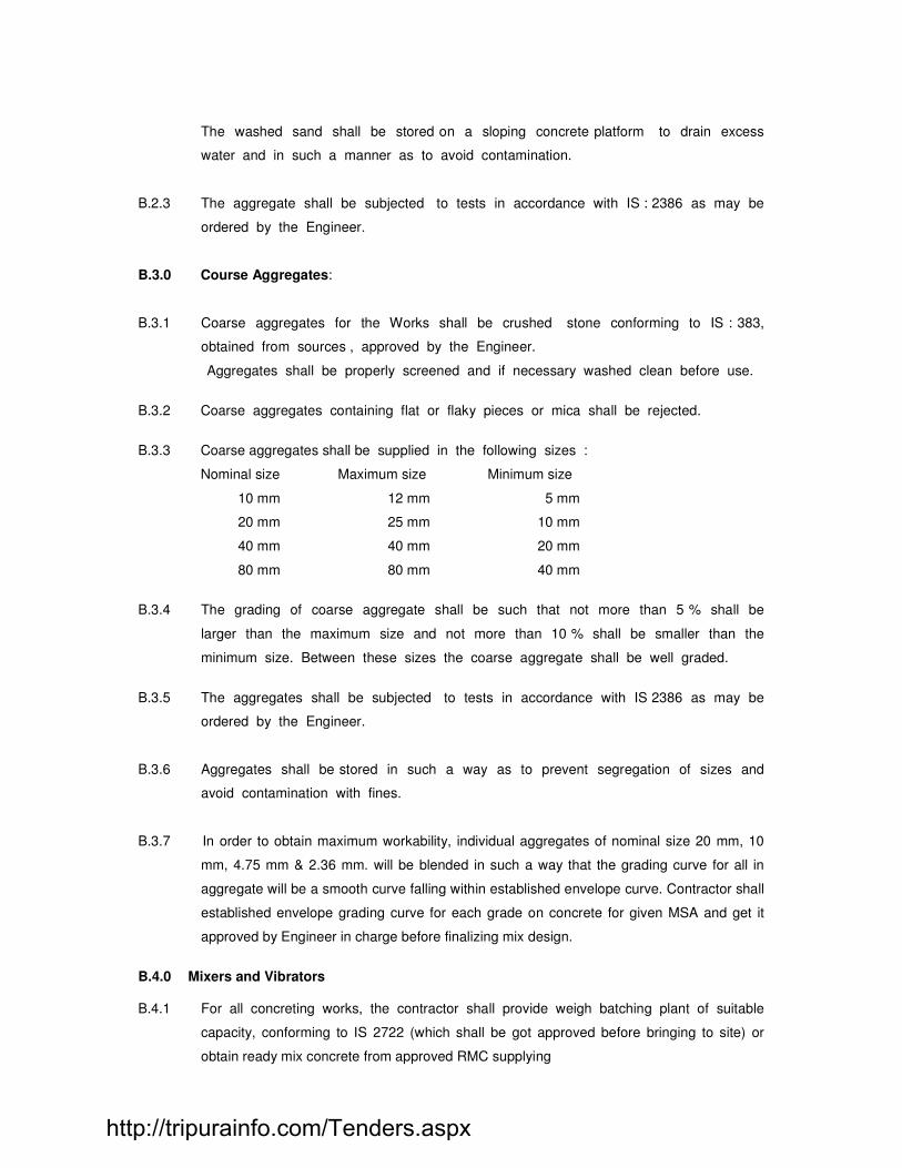
The washed sand shall be stored on a sloping concrete platform to drain excess
water and in such a manner as to avoid contamination.
B.2.3 The aggregate shall be subjected to tests in accordance with IS : 2386 as may be
ordered by the Engineer.
B.3.0 Course Aggregates:
B.3.1 Coarse aggregates for the Works shall be crushed stone conforming to IS : 383,
obtained from sources , approved by the Engineer.
Aggregates shall be properly screened and if necessary washed clean before use.
B.3.2 Coarse aggregates containing flat or flaky pieces or mica shall be rejected.
B.3.3 Coarse aggregates shall be supplied in the following sizes :
Nominal size Maximum size Minimum size
10 mm 12 mm 5 mm
20 mm 25 mm 10 mm
40 mm 40 mm 20 mm
80 mm 80 mm 40 mm
B.3.4 The grading of coarse aggregate shall be such that not more than 5 % shall be
larger than the maximum size and not more than 10 % shall be smaller than the
minimum size. Between these sizes the coarse aggregate shall be well graded.
B.3.5 The aggregates shall be subjected to tests in accordance with IS 2386 as may be
ordered by the Engineer.
B.3.6 Aggregates shall be stored in such a way as to prevent segregation of sizes and
avoid contamination with fines.
B.3.7 In order to obtain maximum workability, individual aggregates of nominal size 20 mm, 10
mm, 4.75 mm & 2.36 mm. will be blended in such a way that the grading curve for all in
aggregate will be a smooth curve falling within established envelope curve. Contractor shall
established envelope grading curve for each grade on concrete for given MSA and get it
approved by Engineer in charge before finalizing mix design.
B.4.0 Mixers and Vibrators B.4.1 For all concreting works, the contractor shall provide weigh batching plant of suitable
capacity, conforming to IS 2722 (which shall be got approved before bringing to site) or
obtain ready mix concrete from approved RMC supplying
http://tripurainfo.com/Tenders.aspx

B.4.2 The Contractor shall provide concrete mixers (IS : 1791) - Batch type concrete mixers,
(IS : 2439) - Roller Pan Mixer.
B.4.3 The Contractor shall provide at site concrete Vibrators, Immersion Type Also
suitable capacity form vibrators will be used.
B.5.0 Grade of concrete:
The concrete is designated as follows:-
Concrete M20, M 35, etc. the letter M refers to the mix, the number 30 represents
the characteristic compressive strength of 150 mm size cubes in Mpa at 28 days.
B.6.0 Trial mixes:
B.6.1 The Contractor is entirely responsible for the design of the concrete mixes. The
design is however to be approved by the Engineer, at least 4 weeks before
commencing any concreting in the Works. The Contractor shall make trial mixes
using samples of coarse aggregates, sand, water, cement and plasticiser typical of
those to be used in the works, and which have been tested in an approved
laboratory.
A clean dry mixer shall be used and the first batch discarded. In case of urgency
work, Engineer in charge may allow use of design mix based on 7 days cube test results.
B.6.2 The minimum cement content and maximum water cement ratio for different grades of
concrete and the required average strengths at 28 days for which the mixes shall
be designed shall be in accordance with IS 456-2000. However the slump, requirement
shall be as per the table-1 given below:
B.6.2.1 If the contractor is unable to obtain the required concrete strength, with the above given
minimum dosage of cement, he can with specific approval of Engineer, increase the cement
dosage. In such cases, no extra payment will be made for the use of extra cement.
B.6.2.2 Use of approved super plasticiser, at contractor’s cost is mandatory.
Table 1 given below, shows, the range of slump for concreting in various areas and
conditions.
TABLE - 2
SR.
No.
Area of Concrete work Slump
mm
1a
Structure with exposed inclined surface requiring low slump concrete to
allow proper compaction.
15 to 25
1b Plain C.C. 15 to 25
http://tripurainfo.com/Tenders.aspx

2 R.C.C. structures with widely spaced rebars. I.e. solid columns, piers,
abutments, footings, well-steinings.
40 to 50
3
R.C.C. structures with fair degree of congestion of rebars, viz pier and
abutment caps, box culverts, well curbs, well caps, walls with thickness
greater than 300 mm.
50 to 75
4 R.C.C. and PSC structures, with highly congested rebars viz deck slab,
girders, box girders, walls with thickness less than 300 mm.
75 to 125
5 Under water concreting through tremie, bottom plug, cast in situ piling.
100 to 200
Note :1) The slump of concrete with water will be 25 mm. Any slump in excess of 25 mm,
shall be obtained by adding suitable dose of approved super plasticizer only.
2) In case of ready mix concrete or pumped concrete the slump may be as per the
requirement by adding suitable dose of approved super plastisizer.
B.6.3 The concrete mixes are designed to yield mean strengths (f’ cm) greater than the
corresponding specified characteristic strengths (f ‘ck). The value of the current margin shall
be set as per BSI standards. The concrete mixes shall be designed on the basis of
required strength, impermeability, desired workability, the maximum size of aggregate
and also the various cements. Accordingly the required cement content shall be
ascertained.
B.6.4. For each grade a total of 18 cubes and 3 cylinders of size 150-mm dia and 160 mm
high shall be made. Of these 18 cubes made not more than 6 may be made on
any day and further, of the 6 cubes made in one day not more than 2 each
representing a different batch of concrete shall be tested at the age of 28 days.
The making of the cubes, their curing, storing, transporting and testing shall be in
accordance with Indian standards I.S. 516. After 28 days of curing the cylinders will be
tested for permeability as per MOST Clause 1716.5. The tests shall be carried out in a
laboratory approved by the Engineer.
B.6.5 If the average strength of the concrete cubes falls below the required target
mean strength (f ‘ cm), fresh preliminary mixes for that grade shall be made as
http://tripurainfo.com/Tenders.aspx

before, until the trial mixes yield cubes of compressive strength at 28 days greater
than the required average target mean strength (f ‘ cm) at that age.
B.6.6 Whenever there is a significant change in the quality of any of the ingredients for
concrete, the Engineer may at his discretion order the carrying out of fresh trial
mixes. All costs for trial mixes and tests shall be to the Contractor’s account and
held to be included in the contract rates.
B.6.7 Before commencing the works the Contractors shall submit to the Engineer for
approval full details of all preliminary trial mixes and tests including complete
calculations of mix design and properties of various ingredients.
B.6.8 The Contractor shall carry out trials to establish the correctness of grading of
aggregates, suitability of plasticiser, formwork, mould release agent etc. To obtain
necessary strength and surface finish. All costs of such trial casting shall be included
in the contract rates.
B.6.9 When the proportions of a concrete mix have been approved by the Engineer, the
Contractor shall not vary the quality or source of the materials or the mix without
the written approval of the Engineer.
B.6.10 It is the complete responsibility of contractor to design the concrete mixes, by
approved standard methods and to produce, the concrete confirming to MOST
specifications. It is expected that the contractor employ competent staff to carry out
this work .
B.6.11 where concrete is produced at continuous production unit such as ready mix concrete, the
Engineer in charge may allow use of established mix design, provided it complies with all
requirements of tender specification. In this case, the responsibility of attending required
strength and other properties lies with supplier and contractor. The manufacturer shall
submit detailed calculation for mix design if desired by Engineer in charge.
B.7.0 Concrete Test:
B.7.1 Compressive Strength:
The compressive strength of hardened concrete of all type and grades will be verified by the
following procedure during routine work.
B.7.1.1 Sampling
General:
Sample from fresh concrete shall be taken as per IS 1199 and cubes shall be made, cured
and tested at 28 days in accordance with IS 516.
http://tripurainfo.com/Tenders.aspx
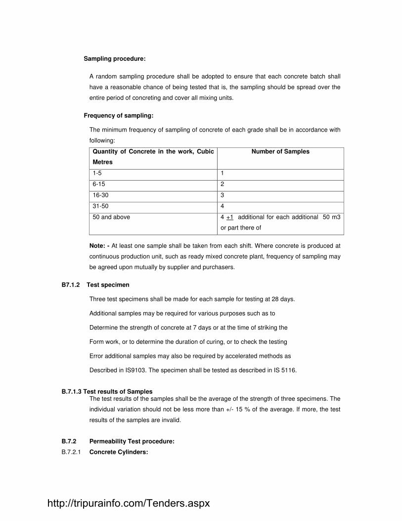
Sampling procedure:
A random sampling procedure shall be adopted to ensure that each concrete batch shall
have a reasonable chance of being tested that is, the sampling should be spread over the
entire period of concreting and cover all mixing units.
Frequency of sampling:
The minimum frequency of sampling of concrete of each grade shall be in accordance with
following:
Quantity of Concrete in the work, Cubic
Metres
Number of Samples
1-5 1
6-15 2
16-30 3
31-50 4
50 and above 4 +1 additional for each additional 50 m3
or part there of
Note: - At least one sample shall be taken from each shift. Where concrete is produced at
continuous production unit, such as ready mixed concrete plant, frequency of sampling may
be agreed upon mutually by supplier and purchasers.
B7.1.2 Test specimen
Three test specimens shall be made for each sample for testing at 28 days. Additional samples may be required for various purposes such as to Determine the strength of concrete at 7 days or at the time of striking the Form work, or to determine the duration of curing, or to check the testing Error additional samples may also be required by accelerated methods as Described in IS9103. The specimen shall be tested as described in IS 5116.
B.7.1.3 Test results of Samples
The test results of the samples shall be the average of the strength of three specimens. The
individual variation should not be less more than +/- 15 % of the average. If more, the test
results of the samples are invalid.
B.7.2 Permeability Test procedure:
B.7.2.1 Concrete Cylinders:
http://tripurainfo.com/Tenders.aspx
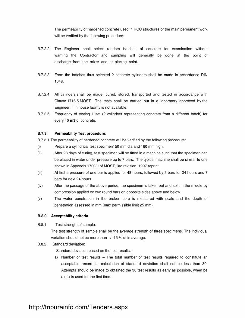
The permeability of hardened concrete used in RCC structures of the main permanent work
will be verified by the following procedure:
B.7.2.2 The Engineer shall select random batches of concrete for examination without
warning the Contractor and sampling will generally be done at the point of
discharge from the mixer and at placing point.
B.7.2.3 From the batches thus selected 2 concrete cylinders shall be made in accordance DIN
1048.
B.7.2.4 All cylinders shall be made, cured, stored, transported and tested in accordance with
Clause 1716.5 MOST. The tests shall be carried out in a laboratory approved by the
Engineer, if in house facility is not available.
B.7.2.5 Frequency of testing 1 set (2 cylinders representing concrete from a different batch) for
every 40 m3 of concrete.
B.7.3 Permeability Test procedure:
B.7.3.1 The permeability of hardened concrete will be verified by the following procedure:
(i) Prepare a cylindrical test specimen150 mm dia and 160 mm high.
(ii) After 28 days of curing, test specimen will be fitted in a machine such that the specimen can
be placed in water under pressure up to 7 bars. The typical machine shall be similar to one
shown in Appendix 1700/II of MOST, 3rd revision, 1997 reprint.
(iii) At first a pressure of one bar is applied for 48 hours, followed by 3 bars for 24 hours and 7
bars for next 24 hours.
(iv) After the passage of the above period, the specimen is taken out and split in the middle by
compression applied on two round bars on opposite sides above and below.
(v) The water penetration in the broken core is measured with scale and the depth of
penetration assessed in mm (max permissible limit 25 mm).
B.8.0 Acceptability criteria B.8.1 Test strength of sample:
The test strength of sample shall be the average strength of three specimens. The individual
variation should not be more than +/- 15 % of in average.
B.8.2 Standard deviation:
Standard deviation based on the test results:
a) Number of test results – The total number of test results required to constitute an
acceptable record for calculation of standard deviation shall not be less than 30.
Attempts should be made to obtained the 30 test results as early as possible, when be
a mix is used for the first time.
http://tripurainfo.com/Tenders.aspx

b) Standard deviation to be brought up to date. The calculation be of the standard
deviation shall be brought up to date after every of mix design and atleast once a
month.
B.8.3 DETERMINATION OF STANDARD DEVIATION:
a) Concrete of each grade shall be analyzed separately to determine it’s
Standard deviation.
b) The standerd deviation of concrete of a given gread shall be calculated using the
following formula from the results of the individual tests of concrete of that grade
obtained by average of the strength of three specimens. The individual variation shall
not be more than +/- 15 % of the average.
Estimated standard deviation = S = 2 / n-1 Where:
= Deviation of individual test standard from the average strength
“n” =number of sample test
B8.4 When significant change are made in the production of concrete batches (for example change
in the material used, mix design, equipment’s of technical control) the standard deviation
value shall be separately calculated for such batches of concrete.
B8.5 ASSUMED STANDERD DEVIATION:
Where a sufficient test results for a particular grade of concrete are not available, the value
of standard deviation to be assumed is 4.60 N/mm2 for 28 days strength and 3.45 N/mm2
for 7 days strength.
B 9.0 Acceptability criteria
B 9.1 Concrete cubes:
B.9.1.1 The strength required of any particular grade of concrete will be considered satisfactory if the
28 days compressive strength of individual sets (each set consist of 3 cubes) and of individual
cubes satisfy the requirement as per IS: 456:2000, clause no.16: Acceptance Criteria.
B.9.1.2 If the concrete procedure at the site does not satisfy the above strength Requirements, the
Engineer in charge will reserve the right to required the contractor to improve the methods of
batching, the quantity of ingredients, and redesign the mix with increased cement content if
necessary. The contractor shall not be entitled to claim any extra cost for the extra cement or
plasticiser used for the modification stipulated by the Engineer I charge for fulfilling the
strength requirements specified.
B.9.2 Permeability Test:
http://tripurainfo.com/Tenders.aspx

The concrete shall pass the permeability test if it is properly compacted and is not
considered permeable when tested as per DIN, and the water penetration in the broken
core is less than 25mm. No extra payment shall be made for this test and cost of the same
will be included in his rate for concrete work.
B.10.0 Failure to meet Specified Requirements :
B.10.1 If from the cube test results it appears that some portion of the works has not
attained the required strength, the Engineer may order that portion of the structure
be subjected to further testing of any kind whatsoever as desired by the Engineer,
including, if so desired by him, full load testing of the suspected as well as
adjacent portions of the structure as specified in the Conditions of Contract. Such
testing shall be at the Contractor’s cost. The Engineer may also reject the work
and order its demolition and reconstruction at the Contractor’s cost.
B.10.2 If the strength of concrete in any portion of the structure is lower than the required
strength, but is considered nevertheless adequate by the Engineer so that demolition
is not necessary, the Contractor shall be paid a lower rate for such lower strength
concrete as determined by the Engineer.
B.10.3 If the concrete is not able to meet the prescribed acceptance standard the effect of such
deficiency on structure shall be investigated by the contractor as directed by the Engineer.
The Engineer may accept the work as sub-standard work. Any additional work required by
the Engineer for such acceptance shall be carried out by the contractor at his cost. Incase
the concrete is not found to be acceptable after investigation; the contractor shall remove
the rejected work forthwith.
B.11.0 Test for concrete and concrete making ingredients:
As frequently as the Engineer may require, testing shall be carried out in the
field for :
1) Moisture content, absorption and density of sand and aggregates.
2) Silt content of and
3) Grading of sand and aggregates
4) Slump, VEBE, FLOW test of concrete for workability.
5) Concrete cube test
6) Permeability test for concrete as per DIN
7) Density and P H value of plasticiser.
8) Tests for water
Before concreting commences on any section of the works contractor shall obtain approval
of the Engineer or his representative as regards the formwork and reinforcement
conforming with the drawings. He shall also indicate to the Engineer in writing and
http://tripurainfo.com/Tenders.aspx

obtain his approval for positions of construction joints. The Engineer or his
representative’s approval shall not relieve the Contractor of any of his obligations to
comply with the provisions of this specification or contract.
B.12.0 Admixtures:
Use of Melamine or Naphtha based approved admixtures is a must. They shall be
permitted by the Engineer provided that the strength and durability requirements are not
affected by their use. The admixture will not be paid for separately. Depending on concrete
pour sequence, retarding super plasticiser shall be used without any extra cost to
CLIENT.
B.13.0 Water:
The Engineer or his representative shall approve the quantity of water to be added to the
mix at mixer. The quantity of water to be added at mixer, may be adjusted by contractor,
with the approval of Engineer in order compensate for prevailing conditions of surface
moisture and absorption of aggregates and sand. On no account shall the contractor
allow more water to be added to the mix than that specified and approved by
Engineer or his representative. In case extra water becomes necessary,
corresponding extra quantity of cement will be added by the contractor at his cost
to maintain the designed W/C ratio approved by Engineer. Concrete containing
excess water, which vitiates design W/C ratio shall be rejected.
B.14.0 Batching of Concrete ingredients :
For all structural concreting, only Ready Mixed Concrete (R.M.C.) manufactured at site in
automatic weigh batching plant, or obtained from approved R.M.C. supplying agencies or
produced at site using mechanical mixer and weigh batchers as per item description, will be
used. The R.M.C. supplying agency will supply mix design details in advance before start
of delivery. For non structural concreting work such as PCC, concrete may be produced at
site using mechanical mixers.
B.15.0 Transporting, placing, compacting, finishing and curing:
Transporting, placing, compacting, finishing and curing of concrete shall be in accordance
with IS: 456.
B.15.1 Transporting:
For all concreting, the concrete after discharge from batching plant will be loaded
in transit mixers and kept continuously agitated while mix is in transit. At
destination the mix will be unloaded in to the hoppers of concrete pump. For site
made concrete suitable prescribed methods shall be adopted.
http://tripurainfo.com/Tenders.aspx

B.15.2 Placing :
The concrete, when discharged from transit mixer in pump hopper shall be kept
continuously agitated and pumped to destination placing point. The height of any
single lift of concrete shall not exceed 1.5 m for walls and 2.0 m for columns.
For columns where the height of pour is more than 2.0m, suitable arrangement in
formwork should be made so that the vertical drop of concrete is restricted to less than
2.0m. Any such arrangement should be approved from the engineer in advance before
execution.
High velocity discharge of concrete causing segregation of mix shall be avoided.
The concrete shall be placed in the forms gently and not dropped from a height
exceeding 1.5 m except in columns where the maximum allowed will be 2.0 m.
Each batch of concrete will be placed in layer. Each layer of concrete shall be
compacted fully before the succeeding layer is placed and separate batches shall
be placed and fully compacted before the layer immediately below has taken initial
set. The layers should be sufficiently shallow, to permit stitching of two layers
together by vibration.
Concreting of any portion or section of the work shall be carried out in one
continuous operation and no interruption of concreting work will be allowed
without approval of the Engineer.
Plain concrete in foundations shall be placed, in direct contact, with the bottom of
excavation, the concrete being deposited in such a manner, as not to get mixed with the
earth. The concrete placed below the ground level shall be protected from falling earth
during and after placing. Concrete placed in ground containing deleterious substances,
shall be kept free from contact, with such ground and with water draining there from
during placing and for a period of 7 days or otherwise instructed there after. Approved
means shall be taken to protect immature concrete from damage by debris, excessive
loading, abrasion, vibrations, deleterious ground water, mixing with earth and other
materials and other influences that may impair strength and durability of concrete.
Before starting of work contractor will get the concrete pouring program and its
sequence approved by Engineer to avoid cold joints.
B.15.3 Compaction :
External, Internal (needle) and surface (screed board) vibrators of approved make
shall be used for compaction of concrete
(a) External and Internal vibrators shall be used for compaction of concrete in
foundations, columns, etc. For sections such as slabs, the concrete shall be
compacted by external, internal and surface type vibrators, depending on the
thickness of layer to be compacted. 25 mm, 40 mm, and 60-mm dia internal vibrators
http://tripurainfo.com/Tenders.aspx

will be used. The concrete shall be compacted by use of appropriate diameter
vibrator by holding the vibrator in position until :
i) Air bubbles cease to come to surface
(ii) Resumption of steady frequency of vibrator after short period of dropping the
frequency, when the vibrator is first inserted.
(iii) The tone of the vibrator becomes uniform.
(iv) Flattened, glistening surface, with coarse aggregates particles blended into it,
appears on the surface.
After the compaction is completed, the vibrator should be withdrawn slowly from
concrete so that concrete can flow in to the space previously occupied by the
vibrator. To avoid segregation during vibration, the vibrator shall not be dragged
through the concrete nor used to spread the concrete. The vibrator shall be made
to penetrate, into layer of fresh concrete below if any, for a depth about
150 mm. The vibrator shall be made to operate at regular pattern of
spacing. The effective radii of action will overlap, approximately half a radius to
ensure complete compaction.
(v) To secure even and dense surfaces free from aggregate pockets, vibration shall be
supplemented by tamping or rodding by hand in the corners of forms and along the
form surfaces while the concrete is plastic.
(vi) A sufficient number of spare vibrators shall be kept readily accessible to the place
of deposition of concrete to assure adequate vibration in case of breakdown of
those in use.
25 mm diameter immersion vibrators shall be used in thin sections upto 125mm, 40
mm diameter immersion vibrators in fairly wide sections like beams, slabs, columns etc.
and 60 mm diameter vibrators in foundations, pilecaps or such large section members.
Screed vibrators shall also be used for slab concreting.
(vii) Plain concrete also shall be vibrated to achieve full compaction, using needle and
screed vibrators as necessary.
B.15.4 Curing :
Curing shall be started at the earliest by spreading wet jute cloth (hessian) and cover
top with plastic sheet and subsequently cured with spraying water. In inaccessible area to
start with, curing be started by spraying curing compound before starting membrane
curing.
B.16.0 Placing temperatures:
During extreme hot weather, the concreting shall be done as per procedures set out
in IS : 7861, Parts I and II.
Fine and coarse aggregates for concreting shall be kept shaded and the concrete
aggregates sprinkled with water for a sufficient time before concreting, in order to
http://tripurainfo.com/Tenders.aspx

ensure that the temperature of these ingredients is as low as possible prior to
batching. The mixer and batching equipment shall be also shaded and if necessary
painted white in order to keep their temperatures as low as possible. The placing
temperature of concrete shall be as low as possible in warm weather and care
shall be taken to protect freshly placed concrete from overheating by sunlight in the
first few hours of its laying. The time of day selected for concreting shall also be
chosen so as to minimize placing temperatures. In case of concreting in
exceptionally hot weather the Engineer may in his discretion specify the use of ice
either flaked and used directly in the mix, or blocks, used for chilling the mixing
water. In either case, no extra payment shall be made to the contractor on this account.
B.17.0 Construction joints :
Construction joints in all concrete work shall be made as directed by the Engineer.
Where vertical joints are required, these shall be shuttered and two coats of
approved surface retarders shall be applied as directed by the Engineer on the
surface of formwork in contact with concrete. The joint concrete shall not be
allowed to take the natural slope of the concrete.
before fresh concrete is placed against a vertical joint, the old concrete shall be
chipped / sand blasted, clean and moistened for 24 hrs. before placing concrete. All
standing water should be removed and dried with compresed air. Neat cement slurry shall
be applied on the chipped / sand blasted surface and mortar of the same water cement
ratio as the concrete and 10 mm thick applied. Where required suitable expansion joint shall
be also provided as directed by Engineer in charge.
The time of day selected for concrete shall be chosen so as to minimize placing
temperature. In case of concreting in exceptionally hot weather the Engineer may in his
discretion specify the use of ice either flaked and used directly in the mix or blocks used for
chilling the mixing water. In eithre case the cost of ice and additional labor involved in
weighing and mixing etc. shall be borne by the contractor and nothing will be paid on this
account.
B18.0 Defective concrete:
Should any concrete be found honey combed or in any way defective, such concrete shall
on the instruction of the Engineer in charge be cut out by the contractor and made good at
his own expenses.
B 19.0 Exposed faces, holes and Fixtures:
On no account shall concrete surfaces be patched or covered up or damaged concrete
rectified or replaced until the Engineer or his representative has inspected the work and
issued written instruction for rectification. Failure to observe this procedure will render that
portion of work liable to rejection, in each case, it will be treated as a work which has failed
to meet specified requirements.
http://tripurainfo.com/Tenders.aspx

Holes for foundation or other bolts or for any other purpose shall be molded, and steel
angles, holdfasts or other fixture shall be embedded, according to the drawing or as
instructed by the Engineer.
B.20.0 Cracks :
B.20.1 If cracks develop in concrete construction, which in the opinion of the Engineer may
be detrimental to the strength of the construction, the contractor at his own expense
shall test the slab or other construction as specified in Special Conditions. If under
such test loads the cracks develop further, the Contractor shall dismantle the
construction, carry away the debris, replace the construction and carry out all
consequential work thereto. Without any extra payment.
B.20.2 If any cracks develop in the concrete construction, which in the opinion of the
Engineer, are not detrimental to the strength of the construction, the contractor at
his own expense shall grout the cracks with polymer cement grout of approved
quality at his own expense and risk and shall make good to the satisfaction of the
Engineer the surface finish which in the opinion of the Engineer has suffered
damage either in appearance or stability owing to such cracks. The Engineer’s
decision as to the extent of the liability of the Contractor in the above matter shall
be final and binding.
B21.0 Finishes:
Unless otherwise instructed the face of exposed concrete placed against formwork shall be
rubbed down immediately on removal of formwork to remove irregularities. The face of
concrete for which form work is not provided other than slabs, shall be smoothed with a
float to give a finish equal to that of the rubbed down face, where formwork is provided. The
top face of the slab which is not intend to be covered with other material shall be leveled
and floated to a smooth finish at the level or falls shown on the drawings or as directed the
floating shall be done so as not to bring an excess of mortar to the surface of the concrete.
The top face of the slab intended to be surface of other material shall be left with a spaded
finish.
Face of concrete intoned to be plastered shall be roughened by approved means to form a
key.
When at site, concrete cube testing machine is used 10 % of the cubes should be tested at
independent recognized laboratories approved by Engineer ,at their cost.
B.22.0 Precast Concrete :
The provision in this section apply to all precast concrete executed within site and shall be
considered supplementary to general provisions for reinforced works.
http://tripurainfo.com/Tenders.aspx
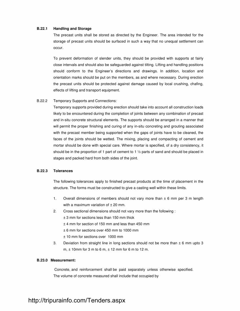
B.22.1 Handling and Storage
The precast units shall be stored as directed by the Engineer. The area intended for the
storage of precast units should be surfaced in such a way that no unequal settlement can
occur.
To prevent deformation of slender units, they should be provided with supports at fairly
close intervals and should also be safeguarded against tilting. Lifting and handling positions
should conform to the Engineer’s directions and drawings. In addition, location and
orientation marks should be put on the members, as and where necessary. During erection
the precast units should be protected against damage caused by local crushing, chafing,
effects of lifting and transport equipment.
B.22.2 Temporary Supports and Connections:
Temporary supports provided during erection should take into account all construction loads
likely to be encountered during the completion of joints between any combination of precast
and in-situ concrete structural elements. The supports should be arranged in a manner that
will permit the proper finishing and curing of any in-situ concreting and grouting associated
with the precast member being supported when the gaps of joints have to be cleaned, the
faces of the joints should be wetted. The mixing, placing and compacting of cement and
mortar should be done with special care. Where mortar is specified, of a dry consistency, it
should be in the proportion of 1 part of cement to 1 ½ parts of sand and should be placed in
stages and packed hard from both sides of the joint.
B.22.3 Tolerances
The following tolerances apply to finished precast products at the time of placement in the
structure. The forms must be constructed to give a casting well within these limits.
1. Overall dimensions of members should not vary more than ± 6 mm per 3 m length
with a maximum variation of ± 20 mm.
2. Cross sectional dimensions should not vary more than the following :
± 3 mm for sections less than 150 mm thick
± 4 mm for section of 150 mm and less than 450 mm
± 6 mm for sections over 450 mm to 1000 mm
± 10 mm for sections over 1000 mm
3. Deviation from straight line in long sections should not be more than ± 6 mm upto 3
m, ± 10mm for 3 m to 6 m, ± 12 mm for 6 m to 12 m.
B.23.0 Measurement:
Concrete, and reinforcement shall be paid separately unless otherwise specified.
The volume of concrete measured shall include that occupied by
http://tripurainfo.com/Tenders.aspx

1 Reinforcement and other metal sections
2 Cast in components each less than 0.01 m3 in volume
3 Rebates, fillets or internal splays each less than 0.005 m2 in cross sectional area.
4 Pockets and holes not exceeding 0.01 m3 in volume
5 Rates for precast concrete shall include demoulding, handling, storing, transporting
and erecting at site, including all clamping, bolting, bracing that may be
required during erection, including erection equipment.
B22.1 In order to exercise the required degree of constant control over the concrete materials and
their proportion, the contractor shall setup and maintained at his own expanses a test
laboratory at the site. He shall
Provide all apparatus required for sensitive testing of concrete and concrete material. In
particular he must have the following equipment set up in the site laboratory.
i) A set of Standard sieves.
ii) Sieve shaker.
iii) Measuring cylinder.
iv) Slump cones.
v) Adequate number of standard moulds.
vi) Weighing balance.
vii) Curing tank for cubes.
viii) Concrete cube testing machine 100 T capacity preferably electrically operated.
Any other apparatus deemed necessary by the Engineer for proper control shall be
provided by the contractor at his own expense. The lab. shall be staffed by qualified
technicians.
When at site, concrete cube testing machine is used 10 % of the cubes should be tested in
CLIENT’S lab. or in lab. Approved by Engineer at contractor’s cost.
B.24.0 READY-MIXED CONCRETE AND PUMPING CONCRETE
The provision in this section apply to all Ready Mix Concrete and shall be considered
supplementary to general provisions for reinforced concrete works.
B.24.1 Ready-mixed concrete may be manufactured in a central automatic weigh Batching
plant and transported to the job in agitating transit mixers.
B.24.2 Coarse Aggregate The maximum size of coarse aggregate shall be limited to one-third of the smallest
inside diameter of the hose or pipe used for pumping. Provision shall be made for
elimination of over-sized particles by screening or by careful selection of aggregates.
To obtain proper gradation it may be necessary to combine and blend certain
fractional sizes of aggregates. Uniformity of gradation throughout the entire job shall
be maintained.
http://tripurainfo.com/Tenders.aspx

The quantity of coarse aggregate shall be such that the concrete can be pumped,
compacted and finished without difficulty.
B.24.3 Fine aggregates:
The gradation of fine aggregate shall be such that 15 to 30 percent should pass the
0.30-mm screen and 5 to 10 percent should pass 0.15-mm screen so as to
obtain a pumpable concrete. Sands that are deficient in either of these two sizes
should be blended with selected finer sands to produce these desired percentages.
With this gradation, sands having a fineness modulus between 2.4 and 2.8 are
generally satisfactory. However, for uniformity, the fineness modulus of the sand
should not vary more than 0.2 from the average value used in proportioning.
B.24.4 Water, Admixtures and slump :
The amount of water required for proper concrete consistency shall take into
account the rate of mixing, length of haul, time of unloading, and ambient
temperature conditions.
Additions of water to compensate for slump loss should not be resorted to nor
should the design maximum water-cement ratio be exceeded. Additional dose of be
retarder be used to compensate the loss of slump at contractor’s cost.
Retempering water shall not be allowed to be added to mixed batches to obtain
desired slump.
B.24.5 Transportation :
The method of transportation used should efficiently deliver the concrete to the point
of placement without significantly altering its desired properties with regard to water-
cement ratio, slump, and homogeneity.
The revolving-drum truck bodies of approved make shall be used for transporting the
concrete. The number of revolutions at mixing speed, during transportation, and
prior to discharge shall be specified and agreed upon. Reliable counters shall be
used on revolving-drum truck units. Standard mixer uniformity tests, conforming to
ASTM standards C 94-69 “Standard Specifications for Ready Mix Concrete”, shall be
carried out to determine whether mixing is being accomplished satisfactorily.
B.24.6 Pumping of concrete :
Only approved pumping equipment, in good working condition, shall be used for
pumping of concrete. Concrete shall be pumped through a combination of rigid pipe
http://tripurainfo.com/Tenders.aspx

and heavy-duty flexible hose of approved size and make. The couplings used to
connect both rigid and flexible pipe sections shall be adequate in strength to
withstand handling loads during erection of pipe system, misalignment, and poor
support along the lines. They should be nominally rated for at least 3.5 Mpa
pressure and greater for rising runs over 30 m. Couplings should be
designed to allow replacement of any section without moving other pipe sections,
and should provide full cross section with no construction or crevices to disrupt the
smooth flow of concrete.
All necessary accessories such as curved sections of rigid pipe, swivel joints and
rotary distributors, pin and gate valves to prevent backflow in the pipe line, switch
valves to direct the flow into another pipe line, connection devices to fill forms from
the bottom up, extra strong couplings for vertical runs, transitions for connecting
different sizes of pipe, air vents for downhill pumping, clean-out equipment etc, shall
be provided as and where required. Suitable power
controlled booms or specialized crane shall be used for supporting the pipe line.
B.24.7 Field control :
Sampling at both truck discharge and point of final placement shall be employed to
determine if any changes in the slump and other significant mix characteristics occur.
However, for determining strength of concrete, cubes shall be taken from the
placement end of line.
B.25.0 Planning :
Proper planning of concrete supply, pump locations, line layout, placing sequence,
and the entire pumping operation shall be made. The concrete production
transportation and placing shall be planned in such a manner that duration between
addition of water during mixing and placing of concrete in desired location is well with in
time limits prescribed by the RMC manufacturer, however this is subjected to fulfillment of
slump and other properties of concrete as specified in tender on failure to adhere to the
time schedule by the supplier the Engineer in charge may reject the concrete.
The pump wherever used should be as near the placing area as practicable, and
the entire surrounding area shall have adequate bearing strength to support
concrete delivery pipes. Lines from pump to the placing area should be laid out
with a minimum of bends. For large placing areas , alternate lines should be
installed for rapid connection when required. Standby power and pumping
equipment should be provided to replace initial equipment, should breakdown occur.
The placing rate should be estimated so that concrete can be ordered at an
appropriate delivery rate.
http://tripurainfo.com/Tenders.aspx

As a final check, the pump should be started and operated without concrete to be
certain that all moving parts are operating properly. A grout mortar should be
pumped in to the lines to provide lubrication for the concrete, but this mortar shall
not be used in the placement.
When the form is nearly full, and there is enough concrete in the line to complete
the placement, the pump shall be stopped and a go-devil inserted and shall be
forced through the line by water under pressure to clean it out. The go-devil should
be stopped at a safe distance from the end of the line so that the water in the
line will not spill into the placement area. At the end of placing operation, the line
shall be cleaned in the reverse direction.
B.26.0 SPECIFICATION FOR FIBER REINFORCEMENT TO BE PROVIDED FOR VACUUM
DEWATERED CONCRETE WEARING COURSE.
B.26.1 PRODUCT SPECIFICATION
The fibres shall be manufactured from 100% Virgin Polypropylene, containing no
reprocessed Olefin materials, and manufactured to an optimum gradation with 25
individual unique fiber designs for use as concrete reinforcement and conforming to
ASTP C-1116 type 1114.1.3, ASTM C-1116 Performance level I and residual
strength. The chemical and physical properties shall be as follows :
• Absorption : Nil
• Specific gravity : 0.9
• Lengths : Graded (3mm to 50mm)
• Ignition point : 1100 F (590C)
• Melt Point : 320 F tp 340 F (160 C – 170 C)
• Electrical conductivity : Low
• Thermal Conductivity : Low
• Acid, Salt resistance : High
• Alkali Resistance : 100% Alkali Proof
The fibers shall be compatible with all concrete design and admixtures.
B.26.2 Application
The application rate shall be at the rate of 0.9 Kg/m3 for concrete. It shall be added at
the time of mixing in the batching plant / mixer and mixed for atleast 5 minutes for
ensure uniform distribution within the concrete. The fibers can be added before or
after addition of water to concrete mix.
http://tripurainfo.com/Tenders.aspx
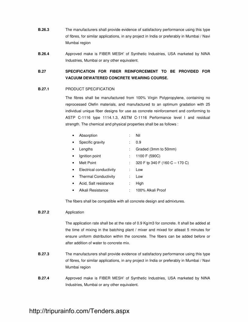
B.26.3 The manufacturers shall provide evidence of satisfactory performance using this type
of fibres, for similar applications, in any project in India or preferably in Mumbai / Navi
Mumbai region
B.26.4 Approved make is FIBER MESH’ of Synthetic Industries, USA marketed by NINA
Industries, Mumbai or any other equivalent.
B.27 SPECIFICATION FOR FIBER REINFORCEMENT TO BE PROVIDED FOR
VACUUM DEWATERED CONCRETE WEARING COURSE.
B.27.1 PRODUCT SPECIFICATION
The fibres shall be manufactured from 100% Virgin Polypropylene, containing no
reprocessed Olefin materials, and manufactured to an optimum gradation with 25
individual unique fiber designs for use as concrete reinforcement and conforming to
ASTP C-1116 type 1114.1.3, ASTM C-1116 Performance level I and residual
strength. The chemical and physical properties shall be as follows :
• Absorption : Nil
• Specific gravity : 0.9
• Lengths : Graded (3mm to 50mm)
• Ignition point : 1100 F (590C)
• Melt Point : 320 F tp 340 F (160 C – 170 C)
• Electrical conductivity : Low
• Thermal Conductivity : Low
• Acid, Salt resistance : High
• Alkali Resistance : 100% Alkali Proof
The fibers shall be compatible with all concrete design and admixtures.
B.27.2 Application
The application rate shall be at the rate of 0.9 Kg/m3 for concrete. It shall be added at
the time of mixing in the batching plant / mixer and mixed for atleast 5 minutes for
ensure uniform distribution within the concrete. The fibers can be added before or
after addition of water to concrete mix.
B.27.3 The manufacturers shall provide evidence of satisfactory performance using this type
of fibres, for similar applications, in any project in India or preferably in Mumbai / Navi
Mumbai region
B.27.4 Approved make is FIBER MESH’ of Synthetic Industries, USA marketed by NINA
Industries, Mumbai or any other equivalent.
http://tripurainfo.com/Tenders.aspx

SECTION - C
FORM WORK
LIST OF BUREAU OF INDIAN STANDARD CODE OF PRACTICE (ISI)
4990- Specification for plywood for concrete shuttering work
3696- Safety code of scaffolds and ladders
4014- Steel and tubular scaffoldings
8989- Safety code for erection of concrete framed structures.
456- Code of practice for plain and reinforced concrete.
C.1 Definition :
The term "Formwork" or "Shuttering" shall include all forms, moulds, sheeting, shuttering
planks, walers, poles, posts, shores, struts and strutting, ties, uprights, waling, steel rods,
bolts, wedges and all other temporary supports to the concrete during the process of setting.
C.2 Materials :
1 All facing formwork to come in contact with concrete in different elements of the structure
shall be of such material and size as specified on drawings or as instructed by the Engineer.
2 Timber facing formwork to come in contact with concrete for "Exposed Concrete Surfaces"
shall consist of lap-jointed or tongue and grooved planks as directed by the Engineer and no
joint shall permit leakage of mortar at all from cast-in-situ concrete.
3 The materials for other backing and supporting formwork and their sizes shall be selected by
the Contractor and shall be subject to the approval of the Engineer.
C.3 Design :
The formwork shall be designed and constructed so that the concrete can be properly placed
and thoroughly compacted to obtain the required shape, position and level subject to
specified tolerances. It is the responsibility of the Contractor to obtain the results required by
the Engineer, whether or not some of the work is sub-contracted. Approval of the proposed
formwork by the Engineer will not diminish the Contractor's responsibility for the satisfactory
performance of the formwork, nor for the safety and co-ordination of all operations. Similarly it
has to be approved by the main consultant.
C.4 Formwork for Exposed Concrete Surfaces :
The facing formwork, unless indicated otherwise on drawings, or specifically approved by the
Engineer in writing, shall generally be made with materials not less than the thickness
mentioned below for different elements of the structure
1 Plain slab soffits, and sides of beams, girders, joists and ribs and side of walls, fins, parapets,
pardis, sun-breakers, etc shall be made with :
a) Steel plates not less than 3mm thick of specified sizes stiffened with a
http://tripurainfo.com/Tenders.aspx

suitable structural framework, fabricated true to plane with a tolerance of +/- 2mm
within the plate.
b) Plywood plates not less than 12mm thick (IS:4990 - Specification for
Plywood for Concrete Shuttering Work) or 3mm thick with a 20mm timber plank
backing, of specified sizes stiffened with a suitable timber framework.
2 Bottoms of beams, girders and ribs, sides of columns shall be made with :
a) Steel plates not less than 5mm thick of specified sizes stiffened with a suitable structural
framework, fabricated true to plane with a tolerance of +/- 2mm within the plate,
b) Timber planks of 35mm actual thickness and of specified surface finish, width and
reasonable length,
c) Plywood plates not less than 12mm thick, of specified sizes stiffened with a suitable
timber framework.
C.5 Erection of Formwork:
The following shall apply to all formwork (procedure approved from consultant):
1 To avoid delay and possible rejection of the formwork, the Contractor shall obtain sufficiently
in advance, the approval of the Engineer for the design of forms and the type of material used
before fabricating the forms. (ref. ACI 347 Formwork for Concrete or equivalent I.S. Code).
The contractor shall take the consultants approval for the procedure for erection of formwork.
2 All shutter planks and plates shall be adequately backed to the satisfaction of the Engineer by
a sufficient number and size of walers or framework to ensure rigidity during concreting. All
shutters shall be adequately strutted, braced and propped to the satisfaction of the Engineer
to prevent deflection under deadweight of concrete and superimposed live load of workmen,
materials and plant, and to withstand vibration. No joints in props shall be allowed.
C.6 Vertical props shall be supported on wedges or other measures shall be taken where the
props can be gently lowered vertically during removal of the formwork. Props for an upper
story shall be placed directly over those in the storey immediately below, and the lowest props
shall bear on a sufficiently strong area.
1 Care shall be taken that all formwork is set plumb and true to line and level or camber or
better where required and as specified by the Engineer.
2 Provision shall be made for adjustment of supporting struts where necessary. When
reinforcement passes through the formwork care should be taken to ensure close fitting joints
against the steel bars so as to avoid loss of fines during the compaction of concrete.
3 If the formwork is held together by bolts or wires, these shall be so fixed that no iron will be
exposed on surfaces against which concrete is to be laid. In any case wires shall not be used
with exposed concrete formwork. The Engineer may at his discretion allow the Contractor to
use tie-bolts running through the concrete and the Contractor shall decide the location and
http://tripurainfo.com/Tenders.aspx

size of such tie-bolts in consultation with the Engineer. Holes left in the concrete by these tie-
bolts shall be filled as specified by the Engineer at no extra cost.
4 Provision shall be made in the shuttering for beams, columns, and walls for a port hole of
convenient size so that all extraneous materials that may be collected could be removed just
prior to concreting.
5 Formwork shall be so arranged as to permit removal of forms without jarring the concrete.
Wedges, clamps and bolts shall be used wherever practicable instead of nails.
The formwork for beams and slabs shall be so erected so that forms on the sides of the
beams and the soffit of slabs can be removed without disturbing the beam bottoms or props
under beams.
6 Surfaces of forms in contact with concrete shall be oiled with a mould oil of approved quality
or clean diesel oil. If required by the Engineer the contractor shall execute different parts of
the work with different mould oils to enable the Engineer to select the most suitable. The use
of oil which results in blemishes of the surface of the concrete shall not be allowed. Oil shall
be applied before reinforcement has been placed and care shall be taken that no oil comes in
contact with the reinforcement while it is being placed in position.
The formwork shall be kept thoroughly wet during concreting and the whole time that it is left
in place.
7 Immediately before concreting is commenced, the formwork shall be carefully examined to
ensure the following:
a) Removal of all dirt, shavings, sawdust and other refuse by brushing and washing.
b) The tightness of joints between panels of sheathing and between these and any hardened
core.
c) The correct location of tie bars, bracing and spacers, and especially connections of bracing.
d) That all wedges are secured and firm in position.
e) That provision is made for traffic on formwork not to bear directly on reinforcing steel.
8 The Contractor shall obtain the Engineer's approval for dimensional accuracy of the work and
for the general arrangement of propping and bracing. (IS:3696 - Safety Code of Scaffolds
and Ladders, IS:4014 Steel Tubular Scaffolding I & II) It is imperative that for scaffolding
heights of 3.6m and above timber posts or steel scaffolding be used with adequate bracings
in horizontal and vertical planes. Bracings with bamboo will not be permitted. When timber
posts are used the bracings shall consist of minimum 25mm thick wooden planks fixed to
each post with at least two nails. The contractor shall be entirely responsible for the
adequacy of propping, and for keeping the wedges and other locking arrangements
undisturbed through the decentering period.
(IS 8989 safety code for erection of concrete framed structures)
http://tripurainfo.com/Tenders.aspx

9 Formwork shall be continuously watched during the process of concreting. If during
concreting any weakness develops and formwork shows any distress the work shall be
stopped and remedial action taken.
C.7 Exposed Concrete Work:
Exposed concrete surfaces shall be smooth and even, originally as stripped without any
finishing or rendering. Where directed by the Engineer, the surface shall be rubbed with
carborundum stone immediately on striking the forms. The Contractor shall exercise special
care and supervision of formwork and concreting to ensure that the cast members are made
true to their sizes, shapes and positions and to produce the surface patterns desired. No
honeycombing shall be allowed. Honeycombed parts of the concrete shall be removed by the
Contractor as directed by the Engineer and fresh concrete placed without extra cost, as
instructed by the Engineer. All materials, sizes and layouts of formwork including the locations
for their joints shall have are prior approval of the Engineer or the Architect.
C.8 Camber:
Forms and false work shall be generally cambered as indicated in the drawings or as
instructed by the Engineer. However, for beams up to 5m span and slabs upto 4m span
camber is not normally required to be provided.
C.9 Tolerances:
In accordance with IS:456.
C.10 Age of Concrete at Removal of Formwork
In accordance with IS:456.
The Engineer may vary the periods specified in IS:456 if he considers it necessary.
Immediately after the forms are removed, they shall be cleaned with a jet of water and a soft
brush.
C.11 Stripping of Formwork
Formwork shall be removed carefully without jarring the concrete, and curing of the concrete
shall be commenced immediately. Concrete surfaces to be exposed shall, where required by
the Engineer, be rubbed down with carborundum stone to obtain a smooth and even finish.
Where the concrete requires plastering or other finish later the concrete surface shall be
immediately hacked lightly all over as directed by the Engineer. No extra charge will be
allowed to the Contractor for such work on concrete surfaces after removal of forms.
C.12 Repropping
For multistoreyed buildings the floors may need repropping to support the loads of the upper
floors under construction. The extent of such repropping shall be as directed by the Engineer
(this does not normally exceed one fourth of the props provided above). Such repropping
shall not be paid for separately and the cost of such repropping shall be deemed to have
been included in the rates.
http://tripurainfo.com/Tenders.aspx
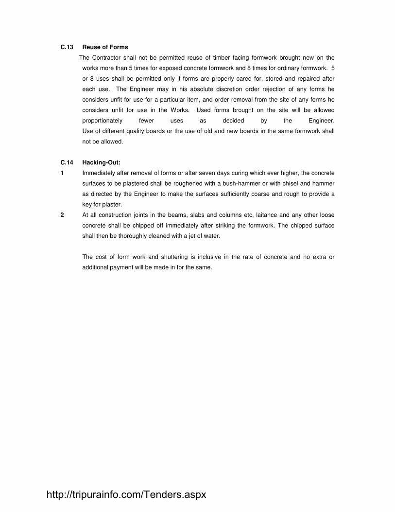
C.13 Reuse of Forms
The Contractor shall not be permitted reuse of timber facing formwork brought new on the
works more than 5 times for exposed concrete formwork and 8 times for ordinary formwork. 5
or 8 uses shall be permitted only if forms are properly cared for, stored and repaired after
each use. The Engineer may in his absolute discretion order rejection of any forms he
considers unfit for use for a particular item, and order removal from the site of any forms he
considers unfit for use in the Works. Used forms brought on the site will be allowed
proportionately fewer uses as decided by the Engineer.
Use of different quality boards or the use of old and new boards in the same formwork shall
not be allowed.
C.14 Hacking-Out:
1 Immediately after removal of forms or after seven days curing which ever higher, the concrete
surfaces to be plastered shall be roughened with a bush-hammer or with chisel and hammer
as directed by the Engineer to make the surfaces sufficiently coarse and rough to provide a
key for plaster.
2 At all construction joints in the beams, slabs and columns etc, laitance and any other loose
concrete shall be chipped off immediately after striking the formwork. The chipped surface
shall then be thoroughly cleaned with a jet of water.
The cost of form work and shuttering is inclusive in the rate of concrete and no extra or
additional payment will be made in for the same.
http://tripurainfo.com/Tenders.aspx
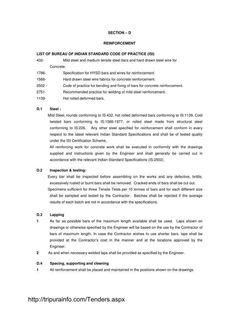
SECTION – D
REINFORCEMENT
LIST OF BUREAU OF INDIAN STANDARD CODE OF PRACTICE (ISI)
432- Mild steel and medium tensile steel bars and hard drawn steel wire for
Concrete.
1786- Specification for HYSD bars and wires for reinforcement
1566- Hard drawn steel wire fabrics for concrete reinforcement.
2502 - Code of practice for bending and fixing of bars for concrete reinforcement.
2751- Recommended practice for welding of mild steel reinforcement.
1139- Hot rolled deformed bars.
D.1 Steel :
Mild Steel, rounds conforming to IS:432, hot rolled deformed bars conforming to IS:1139, Cold
twisted bars conforming to IS:1566-1977, or rolled steel made from structural steel
conforming to IS:226. Any other steel specified for reinforcement shall conform in every
respect to the latest relevant Indian Standard Specifications and shall be of tested quality
under the ISI Certification Scheme.
All reinforcing work for concrete work shall be executed in conformity with the drawings
supplied and instructions given by the Engineer and shall generally be carried out in
accordance with the relevant Indian Standard Specifications (IS:2502).
D.2 Inspection & testing:
Every bar shall be inspected before assembling on the works and any defective, brittle,
excessively rusted or burnt bars shall be removed. Cracked ends of bars shall be cut out.
Specimens sufficient for three Tensile Tests per 10 tonnes of bars and for each different size
shall be sampled and tested by the Contractor. Batches shall be rejected if the average
results of each batch are not in accordance with the specifications.
D.3 Lapping
1 As far as possible bars of the maximum length available shall be used. Laps shown on
drawings or otherwise specified by the Engineer will be based on the use by the Contractor of
bars of maximum length. In case the Contractor wishes to use shorter bars, laps shall be
provided at the Contractor's cost in the manner and at the locations approved by the
Engineer.
2 As and when necessary welded laps shall be provided as specified by the Engineer.
D.4 Spacing, supporting and cleaning
1 All reinforcement shall be placed and maintained in the positions shown on the drawings.
http://tripurainfo.com/Tenders.aspx

2 The Contractor shall provide at his own cost approved types of supports as specified on the
drawings for maintaining the top bars of the slab in position during concreting. All cover
blocks shall be of concrete (not sand cement mortar) and of the same strength as that of the
surrounding concrete and properly compacted. They shall be circular in shape and not
square.
3 The Contractor to provide chairs at his own cost 18 SWG GI wire shall be used as binding
wire. All bars crossing one another shall be bound with this wire twisted tight to make the
skeleton or network rigid so that the reinforcement is not displaced during placing of concrete.
4 Bars must be cleaned before concreting commences of all scale, rust or partially set concrete
which may have been deposited there during placing of a previous lift of concrete.
The bars shall be cleaned with dry gunny bags if they are coated lightly with rust or other
impurities. On no account shall the bars be oiled or painted nor shall mould oil used on the
formwork be allowed to come in contact with the bars. Cement wash to bars shall not be
permitted.
D.5 Welding
1 Wherever specified all welding shall be carried in accordance with IS:2751. Only qualified
welders shall be permitted to carry out such welding.
2 For cold twisted reinforcement welding operations must be controlled to prevent a supply of
large amounts of heat larger than that can be dissipated. The extreme non twisted end
portion shall be cut off before welding. Electrodes with rutile coating should be used.
3 The welding procedure shall be approved by the Engineer and tests shall be made to prove
the soundness of the welded connection.
D.6 Measurement:
1 The weight of steel to be paid for at the contract rates shall be the weight of bars as
mentioned on the drawings or as instructed by the Engineer including stirrups, ties, spacer
bars, chairs and any other steel works specified as reinforcement but excluding binding wire
and cover blocks. Laps as specified on the drawings shall be paid for. Laps required
because of the contractor's use of shorter bars will not be paid for.
2 The weight of any stirrup, tie bar shall be computed from the dimensions given on the
drawings or bending schedules. The weight in kg/metre shall be taken as 0.785 kg/metre per
100mm2 of cross section. No allowance in the weight paid for shall be made for the rolling
margin. No rolling margins will be considered for payments.
3 Measurement of steel should be recorded at site before concreting. The payment will be done
as per the drawings and as per site measurements whichever is less.
4 Rolling margin to be account of and not paid.
SECTION – E
http://tripurainfo.com/Tenders.aspx

STRUCTURAL STEELWORK
LIST OF BUREAU OF INDIAN STANDARD CODE OF PRACTICE (ISI)
226- Code of structural steel (Standard Quality)
2062 - Structural steel code for Fusion welding quality
1599- Method for bend test for steel product.
1608- Method for bend test for steel products.
7205- Safety code for erection of structural steel work.
1477- Code for hot dipped galvanizing
1477 - Hot dipped galvanized
4130 - Demolishing of building (Code of safety)
1200 - Method of measurement of building and civil engineering works
(Part XVIII) demolition and dismantling
E.1 General:
1 Contractor to provide :
The Contractor will provide all materials and equipment required to complete the works in
every respect, whether such materials are required as part of the permanent structures or
temporary for fabrication or erection or maintenance including specifically structural steel
plates, flats, bars, welding rods, rivets, bolts and nuts, paint, welding sets in the shop and at
site,, all workshop facilities, derricks, cranes, pulley blocks, wire ropes, hemp or manila ropes,
winches, erection cleats and temporary braces or supports and all other materials required to
deliver the Works complete in every respect.
All labour required for fabrication and erection for any cleaning, making good, rectifying,
hauling, and painting and for any other ancillary work required to complete fabrication and
erection.
2 The Contractor shall observe all safety requirements for erection of structural steelwork as
covered in IS 7205.
E.2 Drawings:
1 The Engineer will supply to the Contractor profile drawings showing sizes of all structural
members and typical connection details.
2 Should there be any discrepancy in the drawings the Contractor is to refer the matter to the
Engineer. The Contractor shall further provide a drawing showing the accurate setting out to
line and level of all the anchor bolts intended for the work in sufficient time for their inclusion
in the work so as to maintain the building programme.
3 The Contractor is to prepare all the necessary fabrication shop drawings and these shall be
submitted to the Engineer in duplicate and be approved by him before fabrication is
http://tripurainfo.com/Tenders.aspx
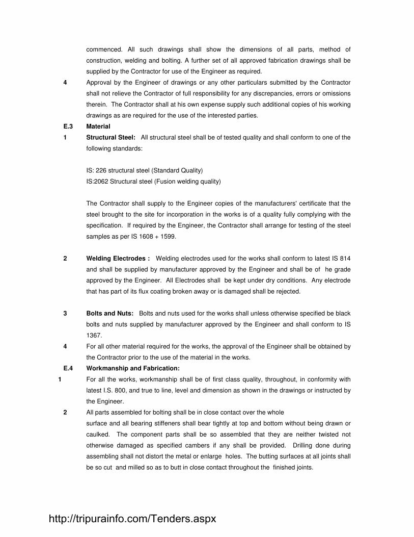
commenced. All such drawings shall show the dimensions of all parts, method of
construction, welding and bolting. A further set of all approved fabrication drawings shall be
supplied by the Contractor for use of the Engineer as required.
4 Approval by the Engineer of drawings or any other particulars submitted by the Contractor
shall not relieve the Contractor of full responsibility for any discrepancies, errors or omissions
therein. The Contractor shall at his own expense supply such additional copies of his working
drawings as are required for the use of the interested parties.
E.3 Material
1 Structural Steel: All structural steel shall be of tested quality and shall conform to one of the
following standards:
IS: 226 structural steel (Standard Quality)
IS:2062 Structural steel (Fusion welding quality)
The Contractor shall supply to the Engineer copies of the manufacturers' certificate that the
steel brought to the site for incorporation in the works is of a quality fully complying with the
specification. If required by the Engineer, the Contractor shall arrange for testing of the steel
samples as per IS 1608 + 1599.
2 Welding Electrodes : Welding electrodes used for the works shall conform to latest IS 814
and shall be supplied by manufacturer approved by the Engineer and shall be of he grade
approved by the Engineer. All Electrodes shall be kept under dry conditions. Any electrode
that has part of its flux coating broken away or is damaged shall be rejected.
3 Bolts and Nuts: Bolts and nuts used for the works shall unless otherwise specified be black
bolts and nuts supplied by manufacturer approved by the Engineer and shall conform to IS
1367.
4 For all other material required for the works, the approval of the Engineer shall be obtained by
the Contractor prior to the use of the material in the works.
E.4 Workmanship and Fabrication:
1 For all the works, workmanship shall be of first class quality, throughout, in conformity with
latest I.S. 800, and true to line, level and dimension as shown in the drawings or instructed by
the Engineer.
2 All parts assembled for bolting shall be in close contact over the whole
surface and all bearing stiffeners shall bear tightly at top and bottom without being drawn or
caulked. The component parts shall be so assembled that they are neither twisted not
otherwise damaged as specified cambers if any shall be provided. Drilling done during
assembling shall not distort the metal or enlarge holes. The butting surfaces at all joints shall
be so cut and milled so as to butt in close contact throughout the finished joints.
http://tripurainfo.com/Tenders.aspx

3 Hand flame cutting will not be permitted.
4 Punching of holes will not be permitted.
5 All welding for the works shall be carried out by first class welders and shall
be in accordance with I.S.S.816/, I.S: 819, I.S. 1024, I.S. 1261 I.S. 1323 and I.S. 9595. The
Engineer may at his discretion order periodic tests of the welder and/or of the welds
produced by them. All such tests, shall be carried out by the Contractor at his cost.
6 As much work as possible shall be welded in shops. The pieces shall be manipulated to
ensure down hand welding for all shop joints as far as possible. All parts to be welded shall
be arranged so as to fit properly on assembly. After assembly and before the general welding
is to commence the parts are to be tack welded with small fillet or butt welds as the case may
be. The tack welding must be strong enough to hold the parts together but small enough to
be covered by the general welding. The welding procedure shall be so arranged
that the distortion and shrinkage stresses are reduce to a
minimum.
7 All joints required in structure to facilitate transport or erection shall be shown on the drawings
or as specified by the Engineer. Should the Contractor need to provide joints in locations
other than those specified by the Engineer he shall submit his proposals and obtain the prior
sanction of the Engineer for such joints. The lengths of structural shall be the maximum
normally available in the market jointing of shorter length in order to make up lengths
required shall not be permitted.
8 Each piece of steel work shall be marked distinctly before delivery, indicating the position and
direction in which it is to be fixed. Three copies of a complete marking plan are to be
supplied to the Engineer before erection commences.
9 In the case of welded fabrication any distortion remaining in the member after welding
operations are completed shall be rectified by and/or at the expense of the Contractor to the
approval of the Engineer.
10 All members of trusses and lattice girders shall be straight throughout their length, unless
shown otherwise on the drawings, and shall be accurately set to the lines shown on the
drawings. Sheared edges of gussets or other members to be straightened and dressed
where necessary.
11 Templates and jigs used throughout the work shall be all steel. In cases where actual
materials have been used as templates for drilling similar pieces, the Engineer shall decide
whether they are fit to be used as parts of the finished structure.
http://tripurainfo.com/Tenders.aspx

E.5 Testing of Welds
Crane Girders:
Butt welds in top flanges and webs - 100% radiographic testing (IS 2595) of first six welds and
10% thereafter welding of stiffeners, cover plates to flanges, etc. Ultrasonic testing (IS 4260)
of 1 in 5 positions initially, decreased to 1 in 10 position if failures are less than 1 in 10.
Column, Roof elements, Bracing:
Butt welds - Radiographic testing of 5% of welds. Fillet welds - Ultrasonic testing of 1 in 20
Positions decreased to 1 in 50 if failures are less than 1 in 10. Dry testing of all the joints is to
be done
E.6 Protection of Steel Works:
Hot Dipped Galvanizing:
i) Hot dipped galvanizing shall be carried out in accordance with IS-802 (Part II), IS: 5358
and IS:4759.
ii) The steel work, prior to delivery, shall be cleaned for scale, rust, dirt, grease etc. by means of
chipping, scrapping, wire brushing mechanical buffing using skilled operators and dipping in
caustic soda bath and then in a bath containing dilute solution of hydrochloric acid.
iii) The steel shall then be fluxed with ammonium chloride by immersion in a preflexing bath or other
approved means.
iv) After preflexing, the steel shall be dipped into the pure (98.5%) molten Zinc held at a
temperature between 440 degrees Centigrade to 470 degrees Centigrade. Proper
arrangement shall be made to support the member. The size of bath shall be such that it shall
accommodate the individual member in its entirety.
v) The thickness of hot dipped galvanized coating shall be between 75-125 microns or the mass of
zinc coating shall be between 610 to 765 g/m2.
vi) Immediately after the steel has been removed from the bath, it shall be wiped, centrifuged to
remove excess zinc and eliminate irregularities.
vii) Proper vents of approved diameter shall be provided for all box members for proper venting of
the enclosed space.
viii) Care shall be taken to avoid the distortion of the steel member.
E.7 Erection & Site Work
1 The Contractor shall be responsible for checking the alignment and level of foundation and
correctness of foundation bolt centres, well in advance of starting erection work, and shall be
responsible for any consequences for non-compliance thereof. Discrepancies if any shall
immediately be brought to the notice of the Engineer for his advice.
2 During erection the rough handling of fabricated materials such as bending, straining or
pounding with sledges shall be avoided. Any damage to the structure during transportation
or erection shall be immediately rectified by the Contractor at his own cost. The
straightening of bend edges of plates, angles and other sections shall be done by methods
that will not cause fracture.
http://tripurainfo.com/Tenders.aspx

Following the completion of the straightening, the surface of the member shall carefully be
inspected for damage and got approved by the Engineer before further use.
3 The Contractor shall be responsible for accurately positioning, leveling and plumbing of all
steelwork and placing of every part of the structure in accordance with the approved
drawings and to the satisfaction of the Engineer. All stanchion base, beam and girder
bearings etc. shall be securely supported on suitable steel packs. All reference and datum
points shall be fixed near the work site for facilitating the erection work.
4 All equipment used by the Contractor shall be sufficient for the purposed and for the erection
of the steel work, in the time specified in the contract. Any lifting or erecting machinery shall
be to the approval of the Engineer and shall
be removed from the site if he considers such appliances dangerous or unsuitable for their
functions. The approval of the Engineer shall not relieve the Contractor of the responsibilities
for the loads to which the erection equipment shall be called upon to carry. Adequate
arrangement shall be made to resist wind loads and lateral forces arising at the time of
erection.
5 The Contractor is entirely responsible for the stability of the structure during erection and
shall arrange that sufficient tack bolts, braces or guy ropes are used to ensure that work will
remain rigid until final bolting, riveting or welding is completed. The Contractor shall supply
and fix, without extra charge, any temporary bracing which may be necessary.
6 All steelwork shall be erected in the exact position as shown on the drawings. All vertical
members shall be truly vertical throughout and all horizontal members truly horizontal,
fabrication being such that all parts can be accurately assembled and erected. No
permanent bolting, welding or grouting shall be done until proper alignment has been
obtained.
7 At stanchion splices and at other positions where concrete cover to the steel is liable to be
restricted, bolts will be placed with their heads on the outside of the members.
8 All field assembly bolting and welding shall be executed in accordance with the requirements
for shop fabrication excepting such as manifestly apply to shop conditions only. Where steel
has been delivered painted the paint shall be removed before field welding for a distance of
at least 50mm on either side of the joints. The number of washers on permanent bolts shall
not be more than two for the nut and one for the bolt head.
9 Erection to done after applying all coats of paint.
E.8 Rectification of damaged materials
Any error in shop work which prevents the proper assembly and lifting up of the parts by
moderate use of drift pins or reaming or cutting shall be immediately reported to the Engineer
and his approval of the method of rectification obtained in writing. Wrongly fabricated material
whose erection in the field necessitates extra work shall be the responsibility of the
contractor. The entire costs of such operation including the replacement of defective
members, if required, shall be borne by the contractor.
http://tripurainfo.com/Tenders.aspx

E.9 Inspection
1 The contractor shall inform the Engineer of the progress in fabrication and as to when
individual pieces are ready for inspection. All gauge templates necessary to satisfy the
Engineer shall be discretion check the results obtained at the contractor's works by
independent tests and should the material so tested be found unsatisfactory, the cost of
such tests shall be borne by the contractor.
E.10 Grouting of steel bases
1 Before grouting of stanchion bases, the contractor shall take the following action :
1 Inform the Engineer.
2 Clean all holes, openings, recesses and the top of foundations of
all dirt, mud, water, oil or other extraneous matter.
3 A frame shall be placed in position around the base plate with a provision for
placing or injecting grout.
4 The contractor shall provide screed bars or mild steel flats and fix them in
mortar.
5 Holes shall be provided on the stanchion bases for escape of air.
2 Grouting of steel beams, steel stanchions, bases and bearings and
encasement of steelwork will be carried out by the contractor after the steelwork has
been finally aligned and leveled and approval of the Engineer obtained.
3 The bolt sleeves shall be grouted as a separate operation using neat cement grout
of a creamy consistency, which shall be poured in so as to completely fill the holes.
"Non-shrink" cements, additives of approved makes shall be used for all grouting
operations.
4 The space between the top of the foundations and the underside of the
base plate shall be completely filled with a mix 1:2 cement sand mortar and finished
flush with edge of the base plate, either :
1 Mixed as a stiff mortar well rammed into place from all sides.
2 Mixed as thickly as possible consistent with fluidity and poured under a
suitable head and tamped until the space has been properly filled.
E.11 Holding down and Anchor bolts
1 The holding down and anchor bolts should conform to the requirements laid down in
IS:5624 or as directed by the Engineer.
2 Installation : Individual bolts in groups of holding down bolts shall be positioned
accurately within a tolerance of + 6mm. The bolts shall be set vertically to a
tolerance of not more than 1 in 250.
3 During the casting of concrete the contractor shall ensure that space between the
bolt and sleeves is kept clean after removal of shuttering. The contractor shall
http://tripurainfo.com/Tenders.aspx

provide and fix timber plugs to maintain this space in a clean condition. The
projecting threads of bolts shall be protected by approved wrapping materials.
4 Grouting of bolt tubes shall be carried out after the steelwork or equipment have been
aligned, plumbed and leveled.
E.12 Tolerances
1 All tolerances shall be in accordance with IS-7215 unless otherwise specified.
2 The maximum deviation for line and level shall be + 3.0mm for any part of the
structure including for location of column centres.
3 The maximum deviation from plumb for columns shall be + 3.0mm in 10.0m height
subject to a maximum of + 6.0mm in a total height of 30.0m.
4 The deviation at the center of the upper chord member from vertical plan running
through the center of the bottom chord shall not be more than 1/1500 of span but in
no case more than 10.0mm. The lateral displacement of top chord at centre of span
form vertical plane running through centre of supports shall not be more than 1/250 of
the depth of truss but in no case more than 20.0mm
5 The crane rails shall not deviate from the true location by more than +
2.0mm.
E.13 Mode of measurement
1 The pricing must include for all rolling margins, extras for length and size, allowance
for waste, complete fabrication, delivery and erection, and caulking the gap between
base plate and foundation, and primer coats of paints as specified. The final coats of
paints, however, will be measured and paid separately on the basis of tonnage
fabricated and erected.
2 Any temporary strutting, tieing or anchor bolts, black bolts, fasteners, welding
required to withstand the stresses of erection and carrying of plant are to be included
in the price.
3 The payment for the steelwork will be for the weight of the steelwork actually erected,
i.e. plates, rolled sections, shear connections, cleats, splice plates.
Dimensions of the steelwork will be taken on site or from the actual shop working
drawings as preferred by the Engineer. In calculating the weights of gusset plates,
payment will be made for the least enclosing parallelogram or triangle. For structural
sections the weight will be calculated on lengths actually used with no deduction for
splay cut or mitred end. In case of imported sections, the weights chargeable shall be
the weight according to the relative standards of the country of origin. Full weight of
the bolts and nuts will be paid for as per Indian Standard Codes weights without any
deduction for shanks, etc. No account shall be taken of the weight of weld in
http://tripurainfo.com/Tenders.aspx

calculating the weight of steel work. Erection packing plates bedded in mortar and
wedges shall not be measured but shall be included in the rates. No deduction shall
be made for openings less than 0.1m2 in area measured in plane for
bolt holes. The weight of sheet steel, plate, strips and rolled sections shall be taken
from relevant Indian Standards.
4 Unless otherwise specified, foundation and anchor bolt assemblies shall be
measured separately including nuts and washers.
E14 STAINLESS STEEL ITEMS.
Process of Manufacture
The raw material shall be preferably manufactured by an ISO 9002 accredited plant with good
manufacturing facilities for rolling of stainless steel sheets with proven history of supplies to
critical industrial applications in India and abroad.
There should be in-house testing facilities and quality assurance system, which will
ensure supply of material as per the specification. There should be in-house bending
facilities to get required shape.
Material shall be in form as per requirement in cover width of minimum 1000m for
sheeting. On one side of the sheet continuous marking indicating grade, size
manufacturer’s identification / ISI certification mark, cast number shall be
incorporated using on - line ink jet marking.
Packing, Transportation and Storage
Special care shall be taken during transportation of the material to the site so as to avoid
damages, scratches, removal of coating etc.
SS sheet packing shall be done as per IS 6911.
Proper storage and handling arrangement shall be made by the supplier so as to
make the material available as and when required by the fixing agency.
Material received in good condition will only be accepted.
Testing
http://tripurainfo.com/Tenders.aspx

Original test certificate of the manufacturer shall be made available for the parent material
(stainless steel sheet / coil), indicating the chemical composition, mechanical properties etc.
as per ASTM A 312.
A separate test certificate shall be made available for the resin coating carried out on the
stainless steel sheets.
Sampling for analysis chemical and mechanical test shall be done as per IS 6911 / ASTM.
If desired by the purchaser / client the testing shall be carried out in the presence of client’s
representative in the laboratory approved by the purchaser. All expenses towards the same
shall be borne by the supplier.
The material shall be summarily rejected if the testing results are found non-satisfactory.
Precautions during storage and erection
Sufficient care is to be taken to see that no material is stacked over the Stainless steel
material.
Industrial cloth lined gloves shall be used to avoid scratches / cuts on the labourer’s hand.
Method statement for fixing of stainless steel sheets of the desired profile shall be submitted
and same shall be approved by Engineer-in-charge.
E14.a) HANDRAILS/ LIGHT POLES
Supplying handgrip stainless steel pipe with brackets of various outer diameters as per
architectural drawings and with minimum 1.66 mm thick, should be confirming to ASTM A 312
TP34 and ANSI B 36.19 E schedule 5S. The fabrication shall be of best workmanship. All the
joints shall be finished off in a proper manner, planned. Intermediate joints shall be not
permitted. Sample of handrail section shall be tested in an approved laboratory for chemical
composition.
The handrails shall be erected in accordance with manufacturers specification. It shall be
aligned and kept in plumb by suitable supporting arrangement. Fixing of handrail shall be
done by using 12mm dia wedge bolts or equivalent approved by architect or by welding to
inserts plate. Handrails shall be protected with a layer of clear transparent lacquer based
methacrylic or cellulose butyrate. The coating shall be removed after installation is completed
and after completion of finishing work in the adjoining area. All the joints between civil work
and handrail brackets shall be sealed by applying silicone seal of approved type and make.
MODE OF MEASUREMENT AND PAYMENT
http://tripurainfo.com/Tenders.aspx

Actual weight including that of brackets/flashing as per approved drawings shall be measured
and paid on weight basis. The rate shall include the cost of wedge bolts, silicone sealant,
fixing glue welding to inserts plates and these shall not be measured for the payments.
E15 STAINLESS STEEL ITEMS.
Process of Manufacture
The raw material shall be preferably manufactured by an ISO 9002 accredited plant with good
manufacturing facilities for rolling of stainless steel sheets with proven history of supplies to
critical industrial applications in India and abroad.
There should be in-house testing facilities and quality assurance system, which will ensure
supply of material as per the specification. There should be in-house bending facilities to get
required shape.
Material shall be in form as per requirement in cover width of minimum 1000m for sheeting.
On one side of the sheet continuous marking indicating grade, size manufacturer’s
identification / ISI certification mark, cast number shall be incorporated using on - line ink jet
marking.
Packing, Transportation and Storage
Special care shall be taken during transportation of the material to the site so as to avoid
damages, scratches, removal of coating etc.
SS sheet packing shall be done as per IS 6911.
Proper storage and handling arrangement shall be made by the supplier so as to make the
material available as and when required by the fixing agency.
Material received in good condition will only be accepted.
Testing
Original test certificate of the manufacturer shall be made available for the parent material
(stainless steel sheet / coil), indicating the chemical composition, mechanical properties etc.
as per ASTM A 312.
A separate test certificate shall be made available for the resin coating carried out on the
stainless steel sheets.
Sampling for analysis chemical and mechanical test shall be done as per IS 6911 / ASTM.
http://tripurainfo.com/Tenders.aspx

If desired by the purchaser / client the testing shall be carried out in the presence of client’s
representative in the laboratory approved by the purchaser. All expenses towards the same
shall be borne by the supplier.
The material shall be summarily rejected if the testing results are found non-satisfactory.
Precautions during storage and erection
Sufficient care is to be taken to see that no material is stacked over the Stainless steel
material.
Industrial cloth lined gloves shall be used to avoid scratches / cuts on the labourer’s hand.
Method statement for fixing of stainless steel sheets of the desired profile shall be submitted
and same shall be approved by Engineer-in-charge.
E15.a) HANDRAILS/ LIGHT POLES
Supplying handgrip stainless steel pipe with brackets of various outer diameters as per
architectural drawings and with minimum 1.66 mm thick, should be confirming to ASTM A 312
TP34 and ANSI B 36.19 E schedule 5S. The fabrication shall be of best workmanship. All the
joints shall be finished off in a proper manner, planned. Intermediate joints shall be not
permitted. Sample of handrail section shall be tested in an approved laboratory for chemical
composition.
The handrails shall be erected in accordance with manufacturers specification. It shall be
aligned and kept in plumb by suitable supporting arrangement. Fixing of handrail shall be
done by using 12mm dia wedge bolts or equivalent approved by architect or by welding to
inserts plate. Handrails shall be protected with a layer of clear transparent lacquer based
methacrylic or cellulose butyrate. The coating shall be removed after installation is completed
and after completion of finishing work in the adjoining area. All the joints between civil work
and handrail brackets shall be sealed by applying silicone seal of approved type and make.
MODE OF MEASUREMENT AND PAYMENT
Actual weight including that of brackets/flashing as per approved drawings shall be measured
and paid on weight basis. The rate shall include the cost of wedge bolts, silicone sealant,
fixing glue welding to inserts plates and these shall not be measured for the payments.
E16 HOT DIPPED GALVANIZED STEEL HANDRAILS
http://tripurainfo.com/Tenders.aspx

Supplying hot dipped galvanized steel pipe with brackets, as per architectural drawings.
The fabrication of handrail shall be of best workmanship. All the joints shall be finished off in a
proper manner, planned, and should be approved by Architect, and then it should be sent for
hot dip galvanizing. Hot dip galvanizing shall be confirming to I. S. 1477.
The handrails shall be erected in accordance with manufacturer's specifications. It shall be
aligned and kept in plumb by suitable supporting arrangement. Fixing of handrail shall be
done by using 12mm dia. wedge bolts or equivalent or by welding to inserts plates. One coat
of epoxy based finishing paint to be done after completion of finishing work in the adjoining
area, as per specification of painting. All the joints between civil work and handrail brackets
shall be sealed by applying silicone seal of approved type and make.
MODE OF MEASUREMENT AND PAYMENT
The rate shall be inclusive of cost of all materials including cost of wedge bolts, silicone
sealant, welding to inserts plates, and epoxy based painting. Sections shall be measured and
paid on the running meter basis, used in the work but contractor should consider the cost of
brackets, wedge bolts, applying protective cover, fixing materials, etc while quoting for.
http://tripurainfo.com/Tenders.aspx

SECTION - F
MASONRY WORK
LIST OF BUREAU OF INDIAN STANDARD CODES (ISI)
1077 - Common burnt clay building bricks 2212 - Code of practice for brick work 1129 - Recommendation for dressing of natural building stones 1597 Part - I Code of practice for construction of rubble stone masonry 1805 - Glossary of terms relating to stones, quarrying and dressing 8112 - 43 grade ordinary Portland cement 2250 - Code of practice for preparation and use of masonry mortar 2116 - Sand for masonry mortar BRICKS F.1 All bricks used on the works shall be burnt clay building bricks of second class quality having
minimum crushing strength of 35 kg/cm2 and shall conform to IS:1077 latest. All bricks shall
be uniform in quality and size. The bricks shall be got tested as per IS:3495 latest at the
contractor's cost.
F.2 Bricks shall be unloaded by hand and carefully stacked and all broken bricks shall be
removed from site.
F.3 All bricks shall be subject to inspection on the site and shall be to the approval of the
Engineer who may reject such consignments as are considered by him to be inferior to the
quality specified.
MORTAR F.4 All mortar shall be prepared in accordance with IS:2250 latest. The sand used shall conform
to IS:2116 latest and the water shall conform to relevant clauses of Section B (Concrete) of
this specification. Only river sand should be used. Restamping of set mortar will not be
permitted.
F.5 Unless otherwise specified in the Schedule of Quantities, the cement mortar proportion shall
be as follows :
(i) 115 thk brickwork and hollow blockwork 1:4
(ii) 230 thk brickwork and hollow blockwork 1:6
CONSTRUCTION F.6 All masonry work shall comply with the requirements of IS:2212 latest. It shall be of English
bond. All closure bricks, etc necessary to comply with the requirements of the bond specified
or to break joints effectively shall be procured by the Contractor and used for the work.
http://tripurainfo.com/Tenders.aspx

F.7 Ordinarily there shall be four courses per 0.3m height or in other words, the horizontal bed
joints shall be on average 10mm thick, and the vertical joints 6mm wide. The mortar shall be
worked upto all joints and no hollow space shall be left in any portion of the work. All joints
shall be laid truly horizontal and all vertical joints shall be truly vertical. Masonry work shall be
raised in a uniform manner so that no one portion is being raised more than 1.0m above
another portion at one time.
F.8 For half brickwalls (115mm thk) which exceed 2.0m in height, a reinforced concrete band
75mm thick (concrete band M-15/10) shall be provided at intervals not exceeding 1.0m. The
reinforcement in these bands shall consist of 2 Nos 6mm mild steel rounders with 6mm
binders spaced at 150mm centre to centre. Such band shall also be provided at the free
edge of all masonry work including window cills and top of free standing walls.
F.9 All bricks shall be thoroughly soaked by keeping them under water for at least 12 hours
before use; the practice of dipping bricks in water just before use will not be allowed. All
necessary water cisterns for this purpose shall be
constructed or tubs brought by the contractor to the satisfaction of the Engineer to ensure
proper soaking of bricks.
F.10 No bats or broken bricks are to be used otherwise than as closures. No underburnt or
overburnt bricks shall be used.
F.11 All concrete block work shall conform to IS:2572. Well dried blocks shall be laid dry and shall
only be moistened to the extent required to compensate the absorption of water from the
mortar. Pieces of blocks shall not be used except where they are absolutely necessary to
make a closure.
F.12 Fixtures Fixtures, plugs, frames for doors and windows, etc shall be placed in position while laying the
course and not later by removing bricks/blocks already laid.
F.13 Scaffolding
Scaffolding consisting of timber ballies, bamboos or steel tubular scaffolding adequately
braced to resist all construction loads shall be provided as required by the working stages.
Any holes made in the walls for tying the scaffolding shall be made good by filling solidly with
M-10/10 grade concrete.
F.14 Watering
The brickwork / blockwork shall be kept wet for a period of at least 14 days after laying. The
mortar shall not be allowed to dry at any time.
JOINTS F.15 All unfinished work shall be raked back in courses, unless otherwise directed. When new
work is to be joined to unfinished work, the surface of the unfinished work shall be cleaned
and thoroughly wetted.
F.16 The finished work shall be true in line and level. All uneven irregular and disturbed brickwork
shall be pulled down and rebuilt with fresh brickwork at the contractor's expense.
http://tripurainfo.com/Tenders.aspx
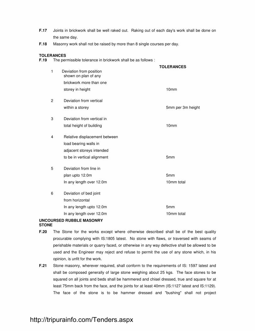
F.17 Joints in brickwork shall be well raked out. Raking out of each day's work shall be done on
the same day.
F.18 Masonry work shall not be raised by more than 8 single courses per day.
TOLERANCES F.19 The permissible tolerance in brickwork shall be as follows :
TOLERANCES 1 Deviation from position shown on plan of any
brickwork more than one
storey in height 10mm
2 Deviation from vertical
within a storey 5mm per 3m height
3 Deviation from vertical in
total height of building 10mm
4 Relative displacement between
load bearing walls in
adjacent storeys intended
to be in vertical alignment 5mm
5 Deviation from line in
plan upto 12.0m 5mm
In any length over 12.0m 10mm total
6 Deviation of bed joint
from horizontal
In any length upto 12.0m 5mm
In any length over 12.0m 10mm total
UNCOURSED RUBBLE MASONRY STONE
F.20 The Stone for the works except where otherwise described shall be of the best quality
procurable complying with IS:1805 latest. No stone with flaws, or traversed with seams of
perishable materials or quarry faced, or otherwise in any way defective shall be allowed to be
used and the Engineer may reject and refuse to permit the use of any stone which, in his
opinion, is unfit for the work.
F.21 Stone masonry, wherever required, shall conform to the requirements of IS: 1597 latest and
shall be composed generally of large stone weighing about 25 kgs. The face stones to be
squared on all joints and beds shall be hammered and chisel dressed, true and square for at
least 75mm back from the face, and the joints for at least 40mm (IS:1127 latest and IS:1129).
The face of the stone is to be hammer dressed and "bushing" shall not project
http://tripurainfo.com/Tenders.aspx

more than 40mm. The stone shall be clean flat bedded properly selected for their places and
carefully laid with a suitable proportion of smaller stones and
chips to fill up the interstices. The mortar including the constituents shall conform to the
requirements of IS: 2250 latest.
F.22 The whole masonry shall be hand set and solidly bedded in and surrounded with mortar on
every side except the face. There shall be no hollows or dry portions in work nor pinning in
the face and no joint shall be more than 10mm. The face stone shall be flat bedded, shall tail
back and be bound well into the body of the wall and shall not be of a height greater than
either the breadth on face or length of the tail. Through stones covering the whole width or
thickness of the walls, or 600mm long where the walls are thicker than 600mm, shall be
inserted at every 1000mm measured horizontally and vertically. The rate for stone masonry
shall include the extra cost of the through stones. The faces of the walls shall be strictly
straight. The masonry shall be shaded from the sun, and kept wet for not less than 14 days
after completion.
F.23 All fixtures, plugs, frames shall be placed securely as the work proceeds and not after
completion of the masonry. Iron holdfasts shall be given a coating of bitumen to avoid
rusting.
F.24 Scaffolding as described in clause F.13 above shall be provided as required.
MODE OF MEASUREMENTS
F.25 The quoted rate shall cover supply of all materials, manufacture of concrete blocks,
tools, scaffolding, plant, labour and all other incidental work required to complete the work in
accordance with the above specification. All brick and rubble masonry work 230mm and
above shall be measured and be paid on a volume basis (m3). All other masonry work
shall be measured and paid on an area basis (m2).
No deductions shall be made for (1) ends of dissimilar materials like girders, beams, lintels,
rafters, etc upto 500 sq.cm. in section and (2) opening upto 0.1 sq.m. in face area.
Deductions for doors, windows, etc. shall be made for the actual square opening in the
masonry at the frames although the jamb, cills etc. may be splayed. No deduction shall be
made for the embedded portions of items like
cornices, string courses, and corbels etc. which are paid separately on running meter basis.
Floor and roof slabs, cills, lintels and portion of R.C.C. staircases, which occur in the masonry
and are separately paid for shall be deducted.
F.26 Reinforced concrete bands shall be carried out as per clauses of Sections B (Concrete),
Section C (Formwork) and Section D (Reinforcement). But no payment shall be made
separately for providing and fixing in position of shuttering, steel reinforcement and concrete
for these bands in 115 brickwork. The items 115 brickwork includes all the materials, labour
and use of equipment necessary for the satisfactory of construction.
F.27 All the deductions shall be made as per the I.S.1200 (Part iii and iv ) unless otherwise
mentioned.
http://tripurainfo.com/Tenders.aspx

F 28 Providing dry trap rubble stone masonry wall :
General :
The item provides for the dry rubble stone masonry of the specified type of stone for the toe walls,
including necessary excavation etc. complete.
Materials :
The trap stone will be obtained from quarry defined in the special provisions or from other sources
approved by the Engineer. The size of the stone shall be as specified for the item or as per directed
by the Engineer in charge. The stone shall be kept free from dirt, dust, oil, or any other injurious
materials, which may attack the stone or mortar to prevent adhesion of mortar. Stones with skins
shall not be used.
Different categories of stones such as face stones headers, quoins, etc. shall be collected in advance
to suffice at least for a week's requirement and shall be stacked separately category wise.
Method of laying the stones:
The masonry shall be laid to lines, levels, curves and shapes shown in the plans. Fixture, plugs,
frames etc., if any, shall be built in at places shown on the plan or directed by the Engineer while
laying the masonry and not later by removing the stones already laid:
(a) Stones in the hearting shall be laid on their broadest face, which gives better opportunity to fill the
space between stones.
(b) Stratified stones must be laid on their natural beds. All bed joints shall be normal to the pressure
upon them.
(c) In battered walls, the beds of stone and the plane of courses should be at right angles to the batter. (d) The courses of masonry shall ordinarily be pre-determined. They shall generally be of the same
height. Where there is to be a variation in height of courses, larger courses are to be placed at lower
levels, the height of courses decreasing gradually towards the top of the wall, unless plans specify
otherwise due to architectural requirements.
(e) The dry rubble masonry shall confirm to the specifications same as that of uncoursed rubble
masonry except that of the following deviations:
1. The masonry will be without mortar (i.e. dry)
2. The quoins may be dressed like khandkies on the face and need not be rough tooled.
3. The spaces between larger stones shall be filled with spalls as tightly as
possible.
In case of discrepancies in the description the Standard Specifications as per detailed in Rd 74. may
please be referred. The face stones shall be laid without any planning on the exposed faces. In each
course the headers or lines of headers as the case may be shall be kept in position at specified
intervals and with specified laps where such laps are required before the masonry of the layer is
commenced to ensure that they are being laid properly and in required numbers and intervals.
http://tripurainfo.com/Tenders.aspx

Item to include :
Uncoursed rubble masonry includes quoins, headers, etc. and laying of rubble masonry.
Erecting and removing all scaffolding, ladders and use of plant required for execution of the item,
safety of the labour and inspection of the work including compensation for any injury damage etc.
Necessary excavations, dewatering etc. complete.
All labour, use of tools, materials and other items incidental to satisfactory completion of the item.
Mode of measurement and payment :
The quantity of uncoursed rubble masonry to be paid under this item shall be in number of cubic
meters of the finished work including quoins etc., and with the limiting dimensions not exceeding
those shown on the plans or as fixed by the Engineer. The contract rate shall be based on a unit of
one cu. meter of finished masonry. Dimensions shall be measured and individual quantities
calculated correct upto two places of decimals of a meter and cubic meter respectively.
http://tripurainfo.com/Tenders.aspx

SECTION-G
PLASTERING AND POINTING
LIST OF BUREAU OF INDIAN STANDARD CODES (ISI)
1542 - Sand for plaster
8112 - 43 grade ordinary Portland cement
1200
Part - XII Method of measurements of buidling and civil engineering works
(Part XII) Plastering and Pointing
1661 - Application of cement and cement lime plaster
GENERAL:
G.1 All plaster work shall comply to IS-1661 (Application of cement and cement lime plaster
finishes). The cement shall be ordinary Portland cement conforming to IS:8112. The lime shall
conform to IS-712 (Building limes). The sand shall conform to IS-1542 (sand for plaster). The
sand shall not contain any particle larger than 3mm and shall be washed before use.
The use of crushed sand will not be permitted for finishing items like masonry & plaster etc.
PREPARATION OF SURFACES:
G.2 Concrete surfaces shall be roughened by wire brushing, hacking, or bush hammering or
chiselling. If the Engineer is not satisfied with the roughening achieved by these methods he
may order other methods such as washing with acid/applying Hack aid etc.
G.3 Loose layers of dust etc. on surfaces to be plastered shall be washed. The surface shall be
cleaned to remove oil, paint or any other material that might interfere with satisfactory bond
and saturated with water so as to be damp when the plaster is applied.
G.4 To avoid cracks at the junction of concrete with brick/block work the plaster shall be
reinforced at such junctions by fixing standard wire mesh (G.I - expanded metal) as
directed by the Engineer.
http://tripurainfo.com/Tenders.aspx

PROPORTIONING:
G.5 The materials used in the preparation of plaster may be measured either by volume using
gauge boxes or by weight. The mix proportion of lime, unless otherwise stated generally
refers to the volume of putty.
G.6 Cement and Sand Plaster: Cement and sand shall be mixed dry in the required proportions to
obtain a uniform colour. Water shall then be added to get the required consistency for the
plaster.
G.7 Mixing shall be done mechanically in "Mortar Mill". If hand mixing is allowed by the Engineer,
mixing shall be carried out on a clean, water tight platform protected from sun and rain.
APPLICATION:
G.8 Patches of plaster 150mm x 150mm shall be placed about 3m apart as gauge to ensure even
plastering. The mortar shall be firmly applied in a thickness slightly more than the required
thickness and well pressed into the joints, rubbed and leveled with a flat wooden rule to
required thickness.
G.9 All plastering shall be made good upto metal or wooden frames, skirting and around pipes or
fittings.
G.10 For internal plastering, scaffolding shall be erected independent of walls. No members of
scaffolding shall be allowed to be housed in the walls being treated with plaster. Scaffolding
for external plaster shall also be supported independent of walls as far as possible to avoid
patchy appearance.
WETTING & CURING:
G.11 Surfaces to be plastered shall be properly watered and in advance before plastering so as to
keep the surface damp. Plastered surfaces shall be kept thoroughly wet by sprinkling water
for at least 7days as directed by the Engineer. Surface with craziness or cracks shall be
rejected and the contractor shall dismantle such plaster forthwith and apply plaster all over
again, at his cost.
G.12 Sand faced plaster:
The sand faced plaster shall be applied in two coats. The first coat (base coat) shall be of
proportion 1:4 and approximately 15mm thick. The base coat shall be trowelled hard so as to
ensure a permanent bond. The surface of the base shall be thoroughly combed so that 3mm
deep grooves at 12mm apart are formed when the mortar is in the plastic stage. The base
coat shall be cured for at least two days. The second coat shall be applied with the mortar of
http://tripurainfo.com/Tenders.aspx
same proportion but 8mm thickness. The mortar shall contain sand with slightly larger
proportion of coarse material. The surface shall be finished with
a wooden float, and trowelled to get a uniform surface. A sponge dipped in cement water
shall be used with a circular motion to get the sandy appearance.
G.13 Cement & Sand Plaster Smooth Finished:
The cement mortar of the proportions 1 cement to 4 sand shall be applied on all the walls
brick or concrete surfaces specified to a uniform thickness of about 12mm/15mm or 20mm in
one or 2 coats and shall be trowelled smooth using a wooden float. Use of dry cement to
obtain smooth finish trowelling shall not be permitted. Care should be taken to ensure that
the plastered surface does not dry out too quickly and also it is not over trowelled, in order to
avoid crazy cracks.
POINTING:
G.14 The joints of the masonry either brick or stone to be flat / tuck pointed shall be raked to a
depth of about 20mm while the mortar in the joint is still fresh and the joints shall be kept well
wetted till the pointing is done. The mortar for the pointing shall consist of one part cement
and two parts sand and shall be applied to wetted joints uniformly. The joints of the pointed
work
shall be regular and uniform in breadth. The edges of the pointing shall be cut off parallel so
as to leave well defined lines about 200mm apart. The pointing shall be kept well wetted for
five days after the pointing is done.
MEASUREMENT:
G.15 The quoted rates shall include the preparation of surfaces, erection and dismantling of
scaffolding, materials, labour, curing, all tools and equipment required to complete the plaster
work in all respects. The plastered and pointed surfaces shall be measured and paid on an
area basis (m2) for the area actually plastered in accordance with IS:1200 (Part XII). No
separate payment shall be made for curing and finishing around skirting, door and window
frames.
http://tripurainfo.com/Tenders.aspx

SECTION - H
PAINTING
LIST OF BUREAU OF INDIAN STANDARD CODES (ISI)
6278 - Code of practice for white washing and colour washing 2932 - Enamel and synthetic, exterior (a) Undercoating (b) Finishing 2933 - Enamel and synthetic, exterior (a) Undercoating (b) Finishing 5410 - Cement paint 427 - Distemper dry colour as required 428 - Distemper, plastic emulsion colour as required 1200
Part - XIII Method of measurement of buidling and civil engineering works
(Part XIII) White washing, colour washing, distempering and painting of building
surface
1200
Part - XV Method of measurement of buidling and civil engineering works
(Part XV) Painting, polishing, varnishing etc
2395 - Painting of plastered surface
H.1 White washing and colour washing:
White washing and colour washing shall be in general comply with IS:6278 latest. Only freshly
burnt lime of good quality free from stone and other foreign matter shall be used, slaking shall
be done at site with an excess of water and the lime allowed to remain under water for two
days. The mixture of lime and water shall then be drawn off, placed in a suitable receptacle
and clean fresh water added to bring it to the consistency of thin cream. The wash so
prepared shall be strained through a coarse cloth or fine sieve and mixed with gum water.
The quantity of gum to be used shall be at the rate of 2 Kg/m3.
The surface to be white or colour washed shall be thoroughly broomed down so as to remove
all dust and holes if any shall be stuffed with materials similar to the surface.
Three coats of white wash shall be applied with proper fibre brushes. Each coat must be
allowed to dry and will be subject to inspection before the next coat is applied.
The colour wash shall be prepared by adding a solution of water and lime fast pigment boiled
if directed to the lime wash prepared as above which shall be done gradually and stirred until
the required tint is obtained.
http://tripurainfo.com/Tenders.aspx

For all colour wash, a sample must first be applied, allowed to dry and approved by the
Engineer-in-charge before the work proceeds. Even colour
must be obtained. Three coats are to be given. Patchy or streaky work will be rejected and
will be re-executed at the contractor's expense.
H.2 Distempering or painting with oil bound water paints etc
Distemper, washable, shall comply with IS:427 or 428 latest. Ready mixed washable
distemper of an approved brand shall be used. Preparation of distemper from ingredients by
the Contractor shall not be allowed. The tint of distemper shall be as directed by the
Engineer-in-charge and a sample application of it shall be made by the contractor if so
desired.
The surface shall be cleaned and all cracks, holes, irregularities etc shall be repaired to get a
smooth and even surface. It shall be completely dry and dust-free before commencement of
distempering.
H.3 Waterproof cement based paints: IS-5410
The waterproof cement paint shall be of an approved manufacturer such as Snowcem,
Oricem or Super Snowcem, or other equivalent and approved and shall be brought to the site
in original airtight containers with seal intact.
Preparatory work: Surfaces shall be thoroughly cleaned free from dirt, dust, etc by brushing
and washing down with clean water. Any grease, oil paint, varnishes and oil bound washable
distemper shall be removed by means of an approved paint remover.
Mixing and application: The dry cement paint shall be thoroughly mixed with clean fresh
water so as to produce a paint of required consistency which for normal work shall be of
ordinary paints. In mixing and application, the contractor shall conform to manufacturer's
instructions.
Paints for application by brush shall be strained through a paint strainer and paint for spraying
shall be twice strained.
The paint shall be kept stirred during use and no paint which has been mixed for a period
longer than one hour shall be used.
The paint to surface other than rough cast may be applied by means of brushes or spraying
with low pressure pot sprayer. Spraying, however, may only be carried out if the Engineer-in-
charge approves. The paint applied to roughcast surface shall be by means of spraying.
http://tripurainfo.com/Tenders.aspx
Absorbent surface shall be thoroughly dampened so as to give even suction. In dry weather
freshly painted surfaces shall be kept damp for at least 2 days and protected from the sun.
When more than one coat is ordered, subsequent coats shall not be applied until the preceding
coat has thoroughly hardened and is approved.
H.4 Painting: oil paint, synthetic enamel, acrylic, plastic emulsion , texture etc : As per
respective IS Codes 2932, 2933
Paints of approved manufacturer only shall be used and shall be applied as per specifications
of the manufacturer. Paints appropriate for the surface to be painted shall be used.
Painting Plastered Surface IS: 2395
Primer Coat: For plastered surfaces to be painted, the same shall be rubbed down with a dry
brush to remove loosely adhering matter. One coat of cement primer for other approved
primer shall then be applied to the surface. After 24 hours a second coat of primer shall be
applied. All cracks in the surface shall be filled with approved putty. Any uneven surface
shall be made good by applying approved putty.
Final Cost:
The paint shall be constantly stirred and thinned by appropriate thinning agent. It shall be
applied uniformly on the surface. The second coat may be applied within three hours of the
first coat.
Painting old surface:
A surface previously treated with paint or oil bound distemper shall be cleaned properly and
rubbed down with sand paper to ensure proper adhesion. No priming coat would be
necessary.
Where lime and certain type of dry distemper have been used, the surface shall be washed
down with water to remove all traces of alkali. The surface must be allowed to dry for at least
24 hours.
Final coat of paint specified shall then be applied as specified under painting for new plaster
work.
H.5 Quartz reinforced cement, Textured paint
Method of mixing and application of paint will be as per manufacturers specifications.
a) Quartz reinforced paint: For Granules : Providing and applying homogenous coat of not
less than 1.5mm thick silica based 100% acrylic polymer bond, grade granular surface coat in
http://tripurainfo.com/Tenders.aspx
2 pack system of approved shade on a two coat sand faced smooth level plaster without any
keying on plastered surface.
b) For Flakes or Plaster : Providing and applying homogenous coat of not less than 1.5mm
thick dry flakes made from special grade heat treated china clay or as per manufacturer
specification and a 100% acrylic polymer bond exterior grade flakes surface coat in a 2 pack
without any keying on cement plastered surface or trowelling plaster of Renovo or equivalent
make as per Architects instructions and as specified by manufacturer and painting the same
surface with shade as directed by the Architects.
H.6 Mode of measurement & payment :
The quoted rate for painting shall include the cost of preparing and cleaning the surface as
specified, preparing sample of paints for approval, scaffolding and curing wherever required
materials, labour, tools and machinery, etc. and cleaning the floor surface from all dirt, paint,
etc., after painting has been completed. It shall also include the cost of putty, primer coat,
preparation of surface after application of each coat.
Where painted surfaces are to be paid separately, they shall be paid in square metres and the
measurement shall conform to IS:1200 Part (XIII) and (Part XV) latest.
SECTION - J
FLOORING & CLADDING
LIST OF BUREAU OF INDIAN STANDARD CODES (ISI)
1237 - Specification of cement concrete flooring tiles
http://tripurainfo.com/Tenders.aspx
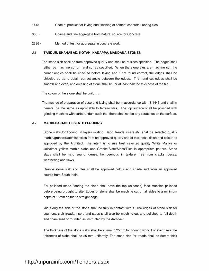
1443 - Code of practice for laying and finishing of cement concrete flooring tiles
383 - Coarse and fine aggregate from natural source for Concrete
2386 - Method of test for aggregate in concrete work
J.1 TANDUR, SHAHABAD, KOTAH, KADAPPA, MANDANA STONES
The stone slab shall be from approved quarry and shall be of sizes specified. The edges shall
either be machine cut or hand cut as specified. When the stone tiles are machine cut, the
corner angles shall be checked before laying and if not found correct, the edges shall be
chiseled so as to obtain correct angle between the edges. The hand cut edges shall be
smooth and even, and dressing of stone shall be for at least half the thickness of the tile.
The colour of the stone shall be uniform.
The method of preparation of base and laying shall be in accordance with IS:1443 and shall in
general be the same as applicable to terrazo tiles. The top surface shall be polished with
grinding machine with carborundum such that there shall not be any scratches on the surface.
J.2 MARBLE/GRANITE SLATE FLOORING
Stone slabs for flooring, in layers skirting, Dado, treads, risers etc. shall be selected quality
marble/granite/slate/slabs/tiles from an approved quarry and of thickness, finish and colour as
approved by the Architect. The intent is to use best selected quality White Marble or
Jaisalmer yellow marble slabs and Granite/Slate/Slabs/Tiles in appropriate pattern. Stone
slabs shall be hard sound, dense, homogenous in texture, free from cracks, decay,
weathering and flaws.
Granite stone slab and tiles shall be approved colour and shade and from an approved
source from South India.
For polished stone flooring the slabs shall have the top (exposed) face machine polished
before being brought to site. Edges of stone shall be machine cut on all sides to a minimum
depth of 15mm so that a straight edge
laid along the side of the stone shall be fully in contact with it. The edges of stone slab for
counters, stair treads, risers and steps shall also be machine cut and polished to full depth
and chamfered or rounded as instructed by the Architect.
The thickness of the stone slabs shall be 20mm to 25mm for flooring work. For stair risers the
thickness of slabs shall be 25 mm uniformly. The stone slab for treads shall be 50mm thick
http://tripurainfo.com/Tenders.aspx

uniformly. Before starting the work, the contractor shall get samples of slabs approved by the
Architect. Tiles shall be of sizes and thickness as called for in the Drawing/Documents.
MORTAR
The slabs shall be laid over a bedding of cement mortar 1:4 (1 Cement : 4 clean coarse
sand) of thickness 20 mm to 30 mm to make up an overall thickness as called for.
LAYING
The RCC slabs for sub-grade concrete over which the slabs are to be laid shall be cleaned,
wetted and mopped. The cement mortar shall be spread over a small area to an average
thickness of 20 mm to 30 mm. The slab, washed clean, shall be laid on the mortar pressed,
tapped, with a wooden mallet and brought to required level. It shall then be removed and laid
aside. The top of the mortar shall then be corrected by adding fresh mortar at hollows. The
mortar of the required consistency shall be spread over the same at the rate of 1 bag per 10
sqm area. The edges of the slab already laid shall be buttered with slurry of cement and
pigment to match the shade of slabs. The slab to be laid shall then be placed back in position,
pressed and properly bedded in level with adjoining slab with as fine a joint as possible. Other
slabs are also laid in similar manner to correct levels with fine joints. The surplus slurry on the
surface shall be cleaned off. Slabs which are fixed in the floor adjoining the wall shall enter
under the skirting or dado as shown on the details. The junction between floor and wall finish
neatly as directed. The flooring shall be cured for minimum seven days. Any slight
unevenness at the meeting of the slabs shall be cured for at least 10 days.
J.3 INLAYS IN MARBLE/GRANITE/SLATE OR STONE FLOORING
Stone slab for inlays in flooring shall be of selected quality from an approved quarry and of
thickness, finish and colour as approved by the Engineer/ Architect.
Specifications for Marble/Granite/Slate flooring shall be applicable for inlays also.
The size of the stone shall be as per drawing, as specified. The stone shall be cut to any odd
shaped size to suit the architectural pattern.
Before laying and fixing the stones on the mortar bed, they shall be assembled dry on the
floor to ensure the correctness of the pattern and to obtain approval from Engineer/ Architect.
J.4 VERTICAL CLADDING IN MARBLE SLATE/GRANITE, KOTAH STONE OR TILES
Vertical cladding includes the work on internal walls, external walls, isolated RCC columns,
etc. Cladding stones or tiles shall be of selected quality from an approved quarry and of
thickness, finish and colour as approved by the Engineer/ Architect.
http://tripurainfo.com/Tenders.aspx

The edges of the exposed right angle corner joints of cladding stones/tiles shall be finished to
suit corner angles, and a groove of 6 mm wide shall be cut, the corner edges polished as per
detail.
Sufficient numbers of groove, 3 mm wide and 1 mm to 2 mm deep, shall be made on the back
of cladding stone/ tiles for proper bonding with mortar or tile adhesive paste.
Wherever specified, chamfers shall be made in the stone.
The joints shall be cut square to the face and shall be at right angles to each other.
MOTOR BACKING
Sand for mortar shall be clean river sand without any salt content.
The thickness of mortar backing specified is nominal and may vary depending upon the
thickness of cladding material used.
SCAFFOLDING
Scaffolding for all cladding work shall be of self supporting type. Holes will not be allowed to
be made in the masonry or RCC work for anchoring the scaffolding.
Contractor shall ensure proper bonding between backing coat & masonry or RCC work by
using approved polymer based bonding agent as per manufacturer's specifications and the
rates shall include the cost of this bonding agent. The surface of backing coat shall be
roughened for proper bonding with the backing of tiles.
CLAMPS
Cladding stones slab shall additionally be held in position by means of stainless steel/gun
metal clamps as specified. The clamps, anchored into the backing masonry/RCC walls or
columns in adequate manner, shall be inserted in holes or grooves drilled in cladding stone
slabs at specified position and the holes or grooves grouted with appropriate mortar. The
number and position of metal clamps shall be as shown in drawing and in any case it shall not
be less than two per stone slab. The size of the stainless steel clamps shall be 20mm wide,
1.5mm to 2mm thick and length to suit the detailing. Stainless steel (or other approved
material) Anchor fasteners shall be 3.4mm to 3.5mm dia and 35mm long. Contractor shall
obtain prior approval from Engineer/ Architect for use of alternatively proven method of fixing
stone slabs.
http://tripurainfo.com/Tenders.aspx

Care shall be taken to protect adjoining works including walls and other elements from
staining or damage by cement slurry. Any gaps by which slurry can escape shall be
temporarily but properly sealed and slurry removed without staining adjoining work.
Expansion joints as per drawing shall be provided in all cladding work. Spacing of joints both
horizontally and vertically shall be between 3 to 4 metres. The face shall be finished as
specified or directed after filling the joints with white cement and matching pigment. The
surface shall be protected from sun and rain and shall be cured for 10 days.
J.5 GRINDING & POLISHING
The grinding and polishing shall be commenced about seven days after the slabs are laid.
The surface shall be watered and ground evenly with a grinding machine using carborundum
stone grade 60. The surface shall then be washed clean and joints grouted with a grout of
cement and appropriate pigment mixed in suitable proportion to match the shade of stone. It
shall then
be allowed to dry for 4 hours and wet, cured for 7 days. The grinding and grouting operation
shall be repeated using carborundum stone grade 80 and 120 till a smooth finished surface is
obtained. After thoroughly cleaning the surface, grouting and curing as described earlier, the
final grinding shall be carried out using carborundum stone grade 320. The surface shall
again be washed clean, dusted over with Oxalic acid at 32 gms per sqm sprinkled with water,
rubbed hard with cotton waste and wiped clean the following day. Where use of machine for
grinding is not feasible rubbing and polishing shall be done by hand in the same manner as
described above.
FINAL POLISH
When all constructional and finishing work namely painting, joinery work, electrical, plumbing
work etc. is completed and just before the area is occupied, the floor shall be worked clean
with dilute oxalic acid solution and dried. Non-slip wax polish shall then be applied with soft
linen on the clean and dry surface and polishing machine fitted with felt or hessian bobs shall
be run over the surface, clean saw dust shall then be spread over the surface, polishing
machine applied again mopping up surplus wax and leaving glossy
surface. Care shall be taken that the floor is not left slippery and that ordinary wax is not used
under any circumstances. The finished surface shall be true to level and lines. The joints shall
be as fine as possible and the surface to finish approved by the Architect.
J.6 PRECAST TILING WORK:
Terrazo tiles, (marble mosaic tiles), plain or coloured tiles, plain or coloured heavy duty
cement floor tiles shall conform to IS:1237 specification for cement concrete flooring tiles :
http://tripurainfo.com/Tenders.aspx

These tiles shall be of approved colour and size and shall be 25mm thick unless otherwise
specified.
Tolerance: Tolerance on length or breadth shall be plus or minus one millimeter and on
thickness plus 3mm.
Wearing layer: Minimum wearing layer shall not be less than 5mm for terrazo tiles and 6mm
for heavy duty tiles and terrazo tiles with 20mm chips. Colour and texture of the wearing layer
shall be uniform throughout its thickness.
Laying of tiles:
IS:1443 Code of Practice for laying and finishing of cement concrete flooring tiles
Surface preparation: Minimum 20mm thick under bed of lime mortar (1:2) machine mixed or
1:4 cement mortar spread uniform on the prepared concrete floor base and compacted to
proper grade. In the case of lime mortar the bed should be left for some time to harden.
J.7 SKIRTING
The skirting shall be of the same materials as that of the floor tiles and shall be of the exact
size specified. It shall be fixed to the wall with cement mortar 1:4 bedding. Grinding and
polishing shall be carried out by hand using carborundum of appropriate quality.
J.8 WHITE GLAZED/ MAT FINISHED CERAMIC, SCREEN PRINTED TILES AND VITRIFIED
TILE FLOORING AND DADO : Tiles shall be of approved make, size and shade as stated in
the Schedule of Quantities or as per the drawing. No crackled, chipped or warped tiles shall
be used in the works. The Architects shall approve all the tiles.
Preparation of surface : All masonry faces shall be cleaned thoroughly by removing dirt,
loose mortar, efflorescence etc. The concrete surfaces shall be brushed to remove all laitance
and roughened to provide a bond for the bedding.
Fixing : The masonry and concrete faces shall be given a coat of cement plaster 15-20 mm
thick (in proportion 1:4). The surface of the plaster shall be scarified with wire brush for getting
a good bond between the tiles and the bedding.
The tiles shall be soaked in clean water for about half an hour before using. The back of the
tile shall be buttered with tile adhesive to a thickness slightly in excess of the finished
thickness required and the tile pressed to the wall and tapped back in position. Joints shall be
uniform, even straight and as thin as possible, in any case not more than 3.0 mm. After tiles
have been fixed, the joints shall be cleaned of adhesive and refilled with cement paste or
http://tripurainfo.com/Tenders.aspx

approved grout of the same shade as that of the tiles. The tiled surface shall be left wet for a
period of 7 days.
Glazed rounded corners, convex or concave shall be provided where specified and no extra
will be paid for the same.
After the completion of the work the surface shall be cleaned of all stains, etc.
J.9 TILE ADHESIVES FOR CLADDING
Contractor shall apply evenly tile adhesive of approved manufacturers on the back of the tile
without leaving any gap for fixing tile to the prepared surface.
The thickness of such paste shall be 3mm to 4mm and special precaution should be taken
when this thickness exceeds while using for tiles for varying thickness. The Contractor shall
ensure that the tile adhesive used shall not leach and leave patches of stain on the finished
surface of tiles.
Adhesive paste, prepared as per manufacturer's specification shall be used within time limit
specified and in no case it shall exceed 15 minutes. If more time has lapsed, fresh paste
should be prepared and used. The cost of tile adhesives shall be included in the rate for
cladding and no extra payment will be made for extra thickness of tile adhesive.
J.10 CERAMIC TILE FLOORING/CLADDING
Ceramic tile flooring where called for, shall be of non-slip ceramic tiles. Spartek or other make
approved by the Architect. The tiles shall be approved colour, size and shape and shall be
laid to the pattern approved by the Architect. The tiles shall be of uniform colour, true to size
and shape and free from cracks, twists, uneven edges, and crazing and other defects. The
tiles shall be generally of size 200x200 mm or as specified.
The tiles shall be laid over a bed of 20 mm thick cement mortar 1:4 (1 Cement: 4 coarse
sand) and levelled to a true surface. The surface of the bedding mortar shall be left rough to
provide bond for the tiles. A floating coat of thick cement slurry shall be laid over the screed to
proper levels and the tiles set over the same firmly to correct line and levels.
The joints shall be filled and finished neat with cement paste pigmented to he shade of the
tile. The joints shall be finished neat as directed and shall be straight, regular and uniform.
http://tripurainfo.com/Tenders.aspx

On completion, the surface shall be washed with water, rubbed with fine sawdust and left
clean.
The finished floor surface shall be true to required levels.
J.11 GLASS MOSAIC TILES
Glass Mosaic tiles shall be set to wall or floor in the following manner :
The surface of the wall or floor is to be plastered with cement mortar 1:4 and allowed to set
for a day. A coat of 12mm thick cement mixed in limewater is to be then spread over the
surface. After about half an hour, a thin coating of white cement for the light coloured tiles or
a coating of grey cement for other coloured tiles is to be then applied. (Adhesives of approved
make are alternative) On this, the sheets of mosaic tiles are to be placed and tapped gently
with a wooden mallet to get the tiles in proper level. The paper is then soaked with water and
peeled out carefully so as not to disturb the tiles from their positions. Any piece not in level or
which is broken while tapping shall be pulled out immediately with a sharp instrument and
then replaced without leaving time for the cement to set. After removing the paper, the
mosaic surface is to be washed with water using a thin brass brush, thus removing the excess
cement. On setting of cement, the tiles shall be polished with fine
cloth or cotton waste. The surface is to be watered twice a day for four to five days.
J.12 PROTECTION OF WALLS AND ADJOINING WORKS
The Contractor shall make at his own cost, all necessary arrangements and take requisite
precautions to ensure that walls and other adjoining works remain protected from any
damages, not only from his own workers/sub-contractor but also from that of other agencies
working in co-ordination at the site of work.
J.13 PVC/ALUMINIUM DIVIDING STRIPS
PVC Dividing strips where called for on the drawings or schedule of finishes shall be
"FIXOPAN" (or other approved make) rigid PVC strips of approved shade. The strips shall be
fixed on the base to the exact surface level of the floor to divide the surface into required
arrangement of panels. The strips cut to profile of the skirting to the full height.
Aluminium strips where called for shall be of the thickness specified.
J.14 MODE OF MEASUREMENT AND PAYMENT
Grano flooring: The rate quoted shall be inclusive of all materials including shuttering if any,
permanent edge supports of specified quality, finishing and curing and cleaning the entire
surface of all matter and dirt.
http://tripurainfo.com/Tenders.aspx

It shall be measured and paid per square metre basis for the specified thickness.
Terrazo tiles, marble mosaic tiles, glass mosaic tiles, cement tiles, insitu mosaic
flooring, marble, kotah stone, granite, stone or tiles, glazed or ceramic tile flooring :
The rate quoted shall be inclusive of all materials, laying, bedding and finishing materials,
cutting the tiles, polishing by grinding machine, curing and cleaning etc. complete.
It shall be measured and paid on square metre basis. The area measured shall be exclusive
of area of inlay if any. When the range of size of stone or tile is specified, the rate shall be
inclusive of cutting stone to any odd shape specified and/or using smaller size of stones or
tiles.
Skirting : Shall be measured and paid as specified on square metre basis.
For treads and risers these shall be measured and paid as specified on square metre basis.
Inlays in marble/granite/slate/stones or tiles
The rate quoted shall be inclusive of all materials and using varieties of stones/tiles in a
pattern as per drawing, cutting the tiles, bedding, finishing materials, using of white cement
with pigment to suit colour of tiles, polishing by grinding machine curing and cleaning etc.
It shall be measured and paid per square meter basis.
Vertical cladding in marble/granite/slate/stones or glazed ceramic tile, vitrified and
glass mosaic
The rate quoted shall be inclusive of all materials, cutting the stones/tiles, making grooves,
and using various types of stone/tiles in a pattern as per drawing, bedding and finishing
materials, approved bonding agents, approved chemical tile adhesive pastes, stainless steel
clamps and bolts, self
supporting scaffolding, providing expansion joints with approved grade
silicone sealant, grouting materials etc. The rate shall also include for cladding on any vertical
surface including isolated columns.
SECTION - K
CARPENTRY, JOINERY, ALUMINIUM DOORS & WINDOWS AND SKY LIGHT
LIST OF BUREAU OF INDIAN STANDARD CODE OF PRACTICE (ISI)
4021 SPECIFICATION FOR TEAK WOOD 287 - Recommendation for maximum permissible moisture content 1141 - Specification for code of practice for seasoning of timber 2202 - Specification for wooden flush shutters
http://tripurainfo.com/Tenders.aspx

401 - Code of practice for preservation of timber 1003 Part I & II Specification for timber paneled and glazed shutters 6534- Code for workmanship in wood work 2338 Specification for code of finishing of joinery. 733 - Specifications for wrought aluminium and aluminium alloys bars and sections 285 Specifications for aluminium alloys bars and sections 1948 - Specifications for aluminium doors, windows and ventilators 1949 - Specifications for aluminium windows for industrial buildings 1477 - Code for hot dipped galvanizing 6248 - Code for rolling shutter
K.1 Teakwood work :
Timber used for joinery shall be of good approved quality or Teak wood unless otherwise
specified (Ref.IS:4021) and shall be well seasoned (IS:1141) cut square, free from excess
wane, from sapwood, dead knot or other defects (Ref.IS:3364).
All timber for carpentry, joinery, rough frame work, backings, grounds, fixing strips and the like
shall be treated with an approved wood preservative (Ref.IS:401) and the Contractor shall
strictly observe the manufacturer's instructions for using this material. The maximum
permissible moisture content in timber shall be in accordance with IS:287-latest.
All workmanship shall be of the best quality (IS:6534) Scantlings and boarding shall be
accurately sawn and shall be of uniform width and thickness throughout. All carpenters' work
shall be left with a sawn surface except where otherwise specified. Work shall be framed
together and securely fixed in the best possible manner and with properly made joints. All
nails, screws, plugs, pins, etc. to be provided as necessary and as directed and approved.
Timber of approved quality is to be purchased at the commencement of the contract for further
seasoning on the site. The preparation of timber is to commence simultaneously with the
beginning of the work generally and to proceed continuously until all the wood work is
prepared and stacked on or near the site. All the timber of large scantlings is to be sawn
immediately on arrival at site to allow for any shrinkage that may take place. All timber
brought to site shall be given anti-termite treatment.
Joints in various members forming any timber frame shall be provided only as shown in the
drawings or as directed by the Engineer. Two millimeters will be allowed for each wrought
http://tripurainfo.com/Tenders.aspx

face of the sizes specified except when described as finished in which case they shall hold to
the full dimensions specified.
All work is to be properly, shouldered, wedged, and pinned, etc. to the satisfaction of the
Engineer and all properly glued with best quality glue.
All joinery shall be finished off in a proper manner, planed and sand papered as required
(IS:2338).
Use of nails shall not be permitted. Fixing of members shall be done by using screws or round
brads, heads of which shall be properly punched in ends of timbers built into walls shall have
air space left between themselves and the walls.
All exposed faces of woodwork shall be sand papered once before erection for approval of the
Engineer. No colour or other preservatives shall be applied without prior approval of the
Engineer.
Frames for doors and windows will be provided with Galvanized Iron holdfasts made of 25mm
x 6mm thick flats 250mm long and fixed into jambs M-20/10 P.C.C. 1200mm high frames with
6 Nos and frames above 2002mm with 8 Nos holdfasts. Each holdfast will be fixed to the
frame with 3 Nos 50mm GI screws.
For fixing timber frames to concrete, rawl plugs and screws of 16 gauge shall be used
wherever specified. Rawl plugs and screws of gauge 16 shall also be used for fixing rawl
rough grounds, framing, hangers, hat hooks, curtain rails etc. Unless otherwise specified,
screws used for the work shall be galvanized.
All timber surfaces coming into contact with masonry or concrete shall be given two coats of
wood preservative or solignum approved by the Engineer.
Paneled and glazed shutters, styles and rails shall be as shown in the drawing, molded and
mortised together (Ref IS:1003). The shutters shall be square and free from twist.
All glazing is to be of float sheet glass of selected quality and approved by the Engineer. It
shall be clear and free from defects make. It shall be cut to the required size and fixed to
frame either with spring clips, with approved quality, or with teakwood beading as per details.
The Engineer may order any timber frame to be put together on the ground and submitted to
suitable tests to his satisfaction before being placed in position. The cost of any such test
shall be borne by the Contractor.
All fixing holes shall be pelted and concealed from view.
http://tripurainfo.com/Tenders.aspx

K.2 40MM THICK FLUSH TYPE BLOCK BOARD (IS:2202)
Shall be manufactured from selected timber well seasoned and construction with 35mm x
25mm thick teak wood lipping all around the edge. The styles and rails shall be of one piece
or alternatively, two or more pieces glued together. The thickness of the cross band shall not
be less than 3mm and the thickness of the facing shall be of best quality commercial ply
thickness not less than 3mm. Where veneer finish, or formica finishes or any other type is
specified they shall be glued separately. All the plywood shall be glued under pressure. Glue
used shall be phenol formaldehyde resins.
K.3 FIXTURES
All doors and windows shall be provided with best quality fixtures as specified in the drawing.
Samples of all fittings shall be submitted for approval by the Engineer. Unless otherwise
specified, hinges, tower bolts, aldrops, handles, baby latches, etc. shall be of best quality
brass oxidized of specified size.
Mortise lock, hydraulic closer and other fixtures shall be of approved make. All the fittings shall
be fixed with brass screws.
K.4 PAINTING
Painting shall be carried out only after the joinery has been inspected and approved by the
Engineer. The surface preparation and applying of primer coats of paint and final coats of
paint shall be carried out as per specifications for painting. Unless otherwise specified a
minimum of 2 coats of primer paint and 3 coats of final paint to be applied.
Where polishing or varnishing is specified, the surface to be varnished or polished shall be
protected from contamination such as inadvertent painting and surface damage. The
polishing or varnishing shall be according to the specifications for varnishing or polishing
under the section Painting.
K.5 ALUMININIUM WINDOWS AND DOORS : IS:1948 & IS:1949
Aluminium alloy shall conform to IS:733 and IS:285. The Contractor shall submit the sample
of section he is proposing to use for the frame, for approval. He shall also indicate the weight
of section per one metre
length.
Aluminium alloy shall conform to IS:733 and IS:285. The Contractor shall submit the sample
of section he is proposing to use for the frame, for approval. He shall also indicate the weight
of section per one metre
length.
http://tripurainfo.com/Tenders.aspx

He shall also submit for approval the sample of hinges, handles, pegstays or any other item
that may require the approval of the Engineer.
The Contractor shall submit shop drawings for assembly and fixing of Doors & windows and
fabrication shall be started only after approval to the shop drawings.
The glass panes, unless otherwise specified, shall be of 5.2mm to 5.5mm thickness for
windows and 5.5mm thickness for doors and shall be free from flaws, specks and bubbles.
They shall have properly squared corners and straight edges.
Fixing to frames shall be done with approved glazing pins and approved EPDM neoprene
gaskets as specified.
Frames consisting of extruded hollow tube sections or other profiles shall be square and flat,
the corners of the frame being fabricated to a true right angle. The hinges shall be either of
projection type, or friction hinges. Necessary coupling of approved shape shall be provided
for composite windows. All holes required for fixing frame, for fixing glazing shall be provided.
Only brass screws shall be used for fixing the frame to concrete members.
Vertical and horizontal members shall be of adequate rigidity to resist lateral forces. Design
calculation shall be submitted for deflection of members.
All the fixtures for center hung shutters, top and bottom hung shutters, or side hung shutters
shall be got approved before they are used. The fixtures used should be such that it should
be possible to open the shutter to any angle. The pins of hinges shall be of stainless steel of
non-magnetic type.
Whatever friction hinges are specified they shall be stainless steel.
Unless otherwise specified, aluminium doors shall be provided with floor springs of approved
quality and make.
All aluminium members shall be supplied in either matt or polished finish including anodizing
them by electrochemical process to an approved colour and to a thickness of average 20-
micron. The frame shall be protected with a layer of clear transparent lacquer based
methacrylates or cellulose butyrate. The coating shall be removed after installation is
completed and after completing finishing work in the adjoining area.
The erection of frame shall be same as detailed under steel windows. Where aluminium
frames come in contact with steel members, they shall be separated by either a 3mm thick
neoprene gasket for full width of aluminium member or any other approved film so as to avoid
metallic corrosion.
http://tripurainfo.com/Tenders.aspx

All joints between Civil work and aluminium work shall be sealed and made airtight by
applying Silicone seal of approved type and make.
Rough ground shall be included in the rates for Aluminum works wherever shown in the
drawing.
SPECIFICATION FOR EXTERNAL SINGLE / DOUBLE GLAZING SYSTEM 1. SCOPE
1.1 This specification defines the requirement of factory made fabricated and Glazed
Single / Double Glazing System consisting of anodized aluminium sections of
approved make with Single / Double Glass (colour as per Architects approval) with
fixed glass panels fitted with silicone sealant using approved make anchorage system
weather seating blocks including accessories to all window panels.
The scope should also include :
• Frameless fixed glazed shop front panel between the two floor slabs.
• Inserts in concrete for the anchorage of all frame works under this scope.
• All sealing and flashing including sealing at junctions.
• Separators. EPDM / Neoprene gaskets, trim, etc.
1. APPLICABLE CODES / PARAMETERS
Glazing should be guaranteed as per following parameters :
• Wind Resistant - UNI EN77, BS-5368 Part-3
• Water Tightness - UNI En86, BS-5368 Part-2
• Air Tightness - UNI EN42, BS-5368 Part-1
• Thermal Insulation - U average value – 1.57 kcal / sq.mts.
• Sound Insulation - R = 30 db for Double glazing and R = 40 db for single glazing.
2. GENERAL
Design, manufacturing and installation of aluminium frames shall be in accordance with the
Architects instructions and details (whenever required and extruded sections used for installing
the frame work shall be of approved manufactures having thickness of 2 mm to 3 mm.
The Contractor shall submit shop drawings showing clearly the relationship of their
external façade works to the structure, mechanical and electrical system, floor slabs
and other related works. Contractor shall show the arrangement of components, the
sequence and details of fabrications assembly and installation of components. They
shall include the following :
http://tripurainfo.com/Tenders.aspx

The Contractor shall also submit samples of joining techniques, relative position of all
adjacent walls, beams, columns and slabs, all correctly dimensioned.
The Contractor to provide the following:
Dimension position of Glass edge/faces relative to metal and similarly provide
dimensions and edge details for aluminium paneling as applicable.
Full size detail, including isometric drawing of sealing, flashing and jointing
methods.
Materials, type, size, location and spacing of all screws, bolts, welds,
anchoring devices and accessories.
The Contractor shall submit a fully detailed programme for the presentation of
shop drawings to the Architect for approval, and in no case shall the
Contractor proceed with any portion of these works without approved shop
drawings.
The shop drawings shall include instructions and explanatory details for the
sequence of fabrication, assembly, erection and the installation of all
materials including the glass and re-glazing procedures.
Details and dimensions of main framing grid as per manufacturers system
comprising of mullions, transoms, panel frames, and weight in Kg. per meter
length of extruded aluminium sections proposed.
Details of brackets connections of mullions to R.C.C. building frame and
connections between transoms and mullions with joint design to withstand
wind forces, earthquake forces, building movement forces etc., as per the
requirements of the specifications contained in this document and the
relevant codes of practice and Structural Design requirements.
Details of weather proofing with E.P.D.M. gaskets of Mac Seal or Eltech or
equivalent and weather stripping and details of sealing with imported
approved make silicons sealant to prevent leakage of rain water under heavy
wind pressure. The E.P.D.M. provided should act as a break in the system to
avoid any contact of aluminium with atmosphere.
http://tripurainfo.com/Tenders.aspx

Infilling Panels of Glass with size of external and internal glass panels in
double glazing minimizing wastage due to cutting and details and properties
regarding glass offered for the external side.
Details of factory fabricated panels complete with factory formed glazing units
ready for quick assembly and erections in positions at site as well as in case
of replacement in any event of breakage of glass by factory glazed panel and
weight in Kg. per meter length of aluminium extruded sections of heavy
gauge in framing.
Insulation of corrosion proof smokes seals of flexible design and construction
to prevent air-conditioning and ventilation loss and ensure complete smoke
seal of cavity spaces.
The Glazing contractor shall furnish the method of erection and installation
also for the Architects approval.
3. FRAMES AND GLAZING
The Glazing shall be fabricated, supplied, erected and installed in position with 6mm thick glass
forming uninterrupted glazed surface in accordance with architectural elevation and layout
drawings. The glazed surface shall be formed by framing system, which shall be of structurally
and mechanically designed technology for fabrication and erection with grid sizes indicated in
the drawing and of full window. The horizontal members shall open in length between vertical
frames. The perimeter of the frames shall be structurally integrated to form air and waterproof
movement joint on all four sides of each panel, Design and sealing of such joints shall ensure
that there is no penetration of rainwater through these joints under heavy wind pressures.
For double glazing the infill panels shall be factory made double glazed unit of size as per design
and consisting of 6mm thick glass of approved make outside and 6mm clear float glass fixed in
precise size on the inner face of the infill panel. The glazed / framing panel shall be formed by
means of imported special structural quality silicone adhesive sealant layer manufactured by
M/s. Dow Corning, USA or equivalent between glazing panel unit and anodized aluminium
framing on all four edges of glasses and internal faces spacer block of required thickness for
the joint formed shall be applied with approved quality imported silicone adhesive sealant as
specified. Double glazing design must limit the working stress of silicone sealant to 138 Kpa.
The applicators of the silicone adhesive structural sealant shall be specially trained tradesmen
certified and approved by the adhesive sealant manufacturer namely Dow Corning U.S.A. The
procedure laid down by the imported adhesive structural sealant manufacturer shall be strictly
followed by these applicators for its application to ensure the high quality and degree of
expertise and finish.
http://tripurainfo.com/Tenders.aspx

All the joints in aluminium framing system and glazed panels as well as joints between aluminium
frame with concrete and / or masonry meeting surrounds shall be fully sealed and made air
water and weather tight preventing seepage of rain water under heavy wind pressures with
provision of adhesive silicone sealant and superior quality of either MACSEAL, ELTECH or
equivalent approved make EPDM gaskets shall be free from contract and migrations stain and
shall be compatible with all substrates. The details complying with this requirement shall be
provided by the contractor along with the tender.
Components of Glazing :
Fixing Bolts, anchors, Screws and nut shall be manufactured from Galvanized M.S. or alloy of
appropriate grade as required. All bolts anchors and others fastening devices shall be self
locking unless otherwise noted shall be torque tightened to achieve maximum torque tension
where required. Brackets shall be Galvanized M.S. of adequate size to meet design
parameters. The bracket joint shall be flexible to allow for all movement deflection and
expansion / contraction. All metals to metal joint shall be separated by tough high impact and
both side smooth membranes of Teflon of minimum 1.0 mm thickness.
Framing System: The framing system consisting of mullions, transoms, head & sills, Sash & Jamb
details shall be of heavy gauge aluminium extruded section to be specially selected to fulfill the
requirement of design criteria stipulated herein after in these specifications and Anodizing in
specified shade.
Vertical Mullions: Contractor to indicate size, shape, spacing, average weight per meter length to
comply with requirement of the specified design parameters. The size of the mullions should
not be less than 84mm x 71mm and thickness of the section should not be less than 2.00mm
and the weight of the mullions should not less than 2.440 kg/meter equivalent to EF-4952.
Side Mullions : The size of the Mullions should not be less than 84mm x 43mm and
thickness of the section should not be less than 2.00mm and the weight of the
mullions should not less than 2.057 kg/meter equivalent to EF-4953.
Horizontal Transom: Contractor to indicate size, shape, spacing and average weight per meter
length. Horizontal transom shall not be visible on the floors when seen through the vision
panels from inside.
The size of the Transoms should not be less than 64mm x 71mm and thickness of the section
should not less than 2.00mm and the weight of the Transoms should not be less than 2.118
kg/meter equivalent to EF-4991.
Materials : aluminium Extrusions of 6063/T6 quality shall be used of HINDALCO / INDAL or
equivalent.
http://tripurainfo.com/Tenders.aspx

1. Glass : Glass panels shall be of required sizes made up of 6mm thick
float glass of approval make and colour of Saint Gobain /
Glavertel / Asahi India or other equivalent approved make.
2 Double Glazing : Double glazed insulated glass is made by bonding two
parallel glass panes in a hermetically sealed unit with a cavity of
dry gas between the sheet of glass. The system is made by
using 6mm thick approved glass of approved make on the outer
surface and 6mm clear float glass of Gujarat Guardian / Float
Glass of India or other approval make inside surface pane. The
system is perfected by separating the glass panes with
aluminium spacer tube, jointed at each corner and fitted with a
special absorbent, which absorbs any remaining moisture. The
unit is then sealed with elastic sealant. The primary seal will be
polyisobutyle and the secondary seal will be weather sealant of
Dow corning.
3 Sealants: Imported silicone adhesive structural sealant DC-995 having
excellent properties of adhesion, elasticity, long life and of
approved make Dow Corning (U.S.A.) shall be used. All the joints
between metal sections in double glazing shall be air and water
light and capable of preventing leakage of rainwater under heavy
wind pressure and under heavy weather conditions. Wherever
the weather sealant is required use DC-789 of Dow Corning.
Directions of the manufacturer of the Sealant shall be strictly
followed.
4 Openable Shutters: Top hung openable window glazed shutters shall be
provided with operating hardware and as per details and
requirements of locations to facilitate ventilation, cleaning and
maintenance of glass as per layout drawings.
5 Finish to aluminum framing member: 20 Micron thick Anodized of approved
shade with PU coating on top for weather protection.
6 The contractor shall furnish details and technical information on all the above
requirements.
7 Framing system and connections to building R.C.C. frame:
http://tripurainfo.com/Tenders.aspx

8 For Single glazing stick type system shall be used and for double glazing
unitized / Semi unitized type system shall be used.
9 Quantities and sizes shall be established by the curtain waller and shall
provide for spares to cover construction breakage and future maintenance.
Openable window shall be provided as per the drawing with required
hardware and shall conform the under mentioned standard.
10 Each pane of glass shall be factory bonded with structural silicone to the
frame. One site glazing shall be limited to constructional of closure panels
only.
11 The entire system shall allow for expansion and contraction and building
movements and shall be self draining at each horizontal panel joint.
Expansion joints details should be submitted for approval.
12 Each panel shall be factory prefabricated, pre-glazed and factory cured, and
then installed on site.
13 Each panel shall have engineered corrosion proof fixing brackets bolted to
the side frames, and bolted to the building structure.
14 Corrosion proof smoke seals of flexible design and construction between the
building structure and the curtain walling shall be provided to ensure a
complete smoke seal of cavity spaces.
15 The design shall be based on the schematic drawings of Architects. The
contractor will be responsible for submitting the design analysis, preparation
of detailed shop drawings for Architects approval. The contractor shall be
responsible for the quality and efficiency of the design and application of the
curtain wall technology required.
It is mandatory that the system be aesthetically pleasing and structurally
sound.
16 Aesthetic Design Features
a) Vision panels, and spandrel panels and soffit panels shall be of high
performance class, selected and manufactured to provide matching
external appearance during the day. All framing shall be neatly and
accurately formed and be of neat and even thickness.
b) The junction between unitized panels shall be true to line in case of
double glazed systems.
http://tripurainfo.com/Tenders.aspx

c) All toughened glass shall have roller lines in a constant direction at all
times.
d) Opening lines shall be extremely frame less in the main facades.
17 The curtain walling shall be designated to with stand the following
forces without failure :
a) Wind loading’s as per IS 875
b) Earthquake Forces as per IS 1893 with important factor 1.5.
c) Building movement – 10mm maximum
18 Before the fabrication of curtain wall, the contractor shall take the actual
measurement of building and carryout necessary correction in the shop
drawing.
19 Acceptance Criteria
a) Deflection – shall be limited to 1/1750
th of the span of the member.
b) No distortion – composition of curtain walling member shall be
adequate to fully resist distortion.
c) Movement – The curtain walling system shall be capable of
accommodating all stress and movements that are likely to occur
during the normal life of 30 years for structural glazing members and
not less than 10 years for structural Silicone Sealant.
d) Plumbing and Alignment – All the members at each joint shall be in
perfect line and alignment. Tolerance for plumb of Structural Glazing
installed shall be within ± 3mm / 10 meter.
e) Warranty – The contractor shall offer a minimum of 10 year
performance warranty for the entire installation carried out and
minimum 10 years guarantee for imported structural silicone sealant
proposed to be used vis-à-vis similar guarantee from the
manufacturer of the silicone sealant to the contractor to fulfill the
quality standards stipulated above
K.6 Rolling Shutters (IS:6248)
http://tripurainfo.com/Tenders.aspx

Rolling shutters shall be as per the size to suit the dimensions of the openings shown in the
drawing. Unless otherwise specified, they shall be fabricated out of 18 gauge thick G.I laths
of convex corrugation with rolling center either 75mm or 65mm and with minimum 12mm
corrugation depth. The laths shall be interlocked by alternate end clips.
The side guides shall either be of rolled section or one piece pressed construction and shall
be of size 25mm wide, 75mm deep, thickness shall not be less than 3mm.
The shutter shall be provided with bottom lock plate 3mm thick and reinforced by an angle iron
stiffener at the bottom and G.I flat at the top.
The suspension shaft shall be of adequate design and unless otherwise specified shall be
formed from 8 gauge seamless tube, 60mm O. D. with suitable flange coupling.
The springs shall be of approved high tensile steel flat or coil spring hardened and tempered.
These shall be fitted inside the fabricated housing.
The ball bearings shall be double self aligning ball bearings fitted inside CI housing fixed on
side brackets holding the suspension brackets at either ends.
The suspension of the shutter shall be bolted on specially fabricated cages formed from G.I.
flats and plates all arc welded.
The hood cover shall be made of 20 gauge G.I sheets with necessary stiffeners and
framework.
The locking arrangement shall consist of hoop and stable on the bottom plate, lockable from
both the sides.
Unless otherwise specified, for overall area of rolling shutters up to 5 sqm pull and push type
hand operated shutters shall be provided. Unless otherwise specified, overall areas of rolls
shall be carried out to manufacturer's specifications. While fixing to concrete members, only
shell anchors shall be used. Chiseling of concrete for fixing bolts will not be allowed.
K.7 ALUMINIUM GRILLS
The work to be carried out as per the manufacturer specifications (deco grill from Hindalco
or other approved manufacturer) and as detailed in
Schedule 'A'
http://tripurainfo.com/Tenders.aspx

K.8 MODE OF PAYMENT AND MEASUREMENT
Wooden doors and windows : The rate quoted shall include the cost of all frames, shutters,
glass panes, if any, and all necessary fixtures, wooden preservatives, fixing them in position
and embedding the holdfasts in concrete and/or fixing the frames to concrete members with
rawl plugs, screws, surface preparation, either applying specified number of coats of
approved paint or polishing complete, and shall be paid on square metre basis.
For measurement of doors, the width shall be overall width of the frame measured prior to
plastering, and height shall be measured from finished floor level to the top of topmost frame
prior to plastering.
For measurement of windows, the width and the height shall be overall frame size measured
prior to plastering.
Where only door shutters are to be paid separately as in the case of partition walls, they shall
be paid on actual dimension of shutters.
Aluminium Doors & Windows: Where specified, in this method aluminium sections shall be
measured and paid on the basis of actual weight used in the work which shall include the
weight of aluminium fixtures such as hinges, handles, including anodizing, applying protective
cover, fixing materials, charges floor springs, door handles etc.
The rate for the glass shall include the cost of all non-aluminium fixtures, such as EPDM
gasket, Nylon rollers, anti rattling pieces, Silicone sealant between frame and civil work etc.,
and the actual area of glass used in the work shall be measured and paid.
Rolling Shutters & collapsible gate: The rate quoted shall include the cost of supplying,
fabricated, fixing in position with shell anchors, or rawl plugs, bolts, all necessary fixtures
including surface preparation and applying paint as specified and shall be paid on square
metre basis.
For measurement the basis shall be overall dimension of the rolling shutter.
Aluminium grill : The rate quoted shall include the cost of supplying, fabricated, fixing in
position with shell anchors, or rawl plugs, bolts, all necessary fixtures including silver
anodizing as specified and shall be paid on square metre basis.
to be finished in gel-coat. Shutters to have recess for hinges. The whole shutter to be totally
water proof resistant to mild acids, alkalies. Colour/ painting as per direction of Engineer-in-
charge.
http://tripurainfo.com/Tenders.aspx
Shutters shall be paid on actual dimension of shutters in square metre.
SECTION – L
LANDSCAPING WORKS
1. SCOPE OF WORK:
The landscape contractor shall from the date of commencement of contract, furnish all materials,
labour, and related items necessary to complete the work indicated and specified herein.
The landscape contractor will be generally responsible for the-entire site but in particular to works
listed below. Along with site management, the responsibilities will include hard landscaping works
(civil works related to landscape) and new horticultural works and planting and maintaining* of these
newly created works for a period of 36 months from the date of virtual completion Le from the day of
complete execution of the entire works - i.e the day of virtual completion as certified by the
LANDSCAPE CONSULTANT.
Maintenance for civil works means ensuring that the constructed works are as intended, cleaned
periodically and not damaged. Maintenance for horticultural works includes watering, manuring,
weeding (weeding upto 1000 mm around planted areas), fertilizing, using of pesticides or fungicides
as required, and other works for the healthy growth of the plants.
After planting, all planted areas that have exposed soil will have to be mulched with straw or hay.
Mulching will be evenly spread to cover any exposed soil.
http://tripurainfo.com/Tenders.aspx

In addition, the contractor will also be responsible for filling gaps, thinning and transplanting, or
replanting where plants may need to be replaced. Along with other planting, the contractor will also be
responsible for improving soil conditions for planting. This may include import /export of sand/soil
to/from site. The contractor will also clear vacant area from existing grasses, keep the site clean and
maintain the already planted areas free of weeds, pests or insects that cause diseases. All weeds,
unwanted- grasses and plant material will be cleared up to 1000mm from the edge of planting of
newly created and already existing horticultural works (such as boundary trees). The contractor will
also be responsible for protection of the plants from salt spray that may occur during the monsoons.
2. STORAGE SHED:
No storage area will be provided at site by the Employer. As mentioned In General Conditions of
Contract, security of materials at site will be the responsibility of the contractor. Any temporary sheds
or structures may be built as working space at the area shown at site and on the approval of the Site
Engineer
3. ESTABLISHMENT OF NURSERY:
Due to the expanse of the project, various plants will have to be propagated at the site. For this
purpose, a shade net area will be made available by the contractor at site. The contractor will be
responsible for the multiplication of plants that will be required on an ongoing basis on the site. The
nursery area will have a shade net area with potting shed.
Approximately 2000 sq. ft. of Shade net area using Netlon brand black colour will be required to be
maintained and replaced whenever necessary, for which no extra payment will be made by the
employer.
It is strongly recommended to actively use the Nursery area for plant propagation and multiplication. It
is expected that the rates quoted herein to be cheaper so as to reflect plants grown in the in house
nursery. The employer may at any point give an order for plants (indoor or otherwise) to be
propagated in the Nursery and compensate accordingly. The contractor will have to have a
satisfactory stock of plants specified in this tender in the nursery and share details of the same with
the employer and its landscape consultant.
The Contractor will be responsible for maintaining adequate number of all varieties of plants that have
been proposed by the Landscape Consultant at any given point of time. The Contractor shall take
approval from the Landscape Consultant regarding the plants stocked I propagated before he
proceeds with planting in the designated areas. He shall also maintain an additional of 20% of the
numbers specified of all the varieties of plants for gap filling and replacement due to mortality.
http://tripurainfo.com/Tenders.aspx

The Contractor will establish the nursery - within two weeks from the date of Letter of Acceptance and
maintain the same for the entire period of the contract and the defects liability period at his own cost.
At end of the defects liability period he shall hand over the nursery to the Accepting Officer with
adequate number of plants of all species required for filling of gaps, replacement etc. that would have
been planted at site as proposed by the Landscape Consultant.
4. WATERING:
Water will be made available at only one source at site. If the water on site is insufficient or saline or
unacceptable, then the contractor shall be responsible for importing water in water tankers for the
general upkeep of the plants. No plants shall be allowed to wither or die due to lack of proper
watering.
5. REPLACEMENT OF PLANTS:
Those plants that are not up to the standards, and do not meet specifications shall be replaced by the
contractor at no extra cost to the Employer.
When the plants are to be replaced either for filling gaps or poor quality, then the contractor shall
replace with plants of equal height, size and age of the plants in that area. For this purpose, extra
numbers of plants of those used in the project will have to be maintained in the Nursery.
The contractor shall be responsible for any thefts of plants already planted. While the Employer will
provide security at entry and exit points, plants removed by theft shall be the responsibility of the
contractor.
6. PLANT REQUIREMENTS:
Plants and shrubs shall be sourced by the contractor from available nurseries, unless otherwise
specified. Seeds shall be acquired from reputed organisations and hybrid seeds will be used where
possible - particularly for flower varieties. No plant material shall be changed without the consent of
the landscape architect.
7. WEEKLY REPORT:
The contractor shall also maintain a work report for work completed each week. The same report in
http://tripurainfo.com/Tenders.aspx

English, will be sent to the landscape architect The landscape architect shall verify completed work as
per the report. Contractor will be responsible for meeting deadlines for the completion of the job.
8. RESPONSIBILITY:
a) The contractor's work shall not hinder' other work, either underground or over ground, such as
electrical, phone lines, water or sewage lines, etc. In areas of overlap, the contractor shall
work in coordination with other related contractors. -Any damage by the landscape
contractor's team to such utilities will be penalized and contractor shall be responsible for cost
for such damages.
b) The contractor shall abide by the Security rules / procedures of the Employer, and shall obtain
gate pass, issue I.D. badges to all their employees on site, etc. as prescribed by the
Employer.
9. MATERIALS & LABOUR:
All materials for civil works will be as specified in the Bill of Quantities, unless otherwise noted.
9.1 PLANT MATERIALS:
All plant materials shall be healthy, found vigorous, free from plant diseases, insect pests or their eggs
and shall have healthy well developed root systems. All plants have to be of specified height and
should be bushy with plenty of leaves. Plants that are not full grown, or are weak and without
adequate leaves will be rejected and not counted towards any payment - partial or full.
Plant supplied shall confirm to the names listed on both the plan and the plant list. Numbers of plants
will vary depending on area at site. Any discrepancy with numbers from those specified in the Tender
should be brought to the attention of the Landscape Architect before proceeding with the work.
9.2 SUPPLY & SUBSTITUTION:
Upon submission of evidence that certain materials including plant materials are not available at the
time of execution, the contractor shall inform the Landscape consultant of the same, who will then
provide an alternative to the species. This species checking has to be done within 15 days from the
list being made available to the contractor.
9.3 EQUIPMENT:
All labour should be provided with tools required for regular maintenance and upkeep of a garden.
http://tripurainfo.com/Tenders.aspx

Lawn mowers, hoses, garden scissors, pruning shears, trowels, spading forks for loosening soil will
be available on the labourers at all times.
Safe custody of these tools / equipment shall be the responsibility of the contractor.
9.4 LABOUR & STATUTES:
All labour force will be of legal age and no child labour will be permitted on site. All payments, salaries
and benefits for the labour force will be the responsibility of the contractor. Contractor shall
compulsorily abide by the statutory provisions with regards to Construct ion Labour Act, Workman's
Compensation Act, Minimum wages Act, etc. and shall insulate the Employer from any claims in these
respects whatsoever.
9.5 TRAINING & MEETINGS:
The labour will be trained to use proper gadgets required and will use them effectively. Periodical
training sessions and meetings' with the labour force, in the presence of the landscape architect, if
necessary, shall be conducted as and when required or called for.
10. PLANTING:
Whenever planting, the following specifications will be followed by the contractor. Wherever sand is to
be removed, the following specifications shall be followed after refilling the area with good soil.
10.1 DIGGING OF PITS:
Tree pits of 900mm x 900 mm x 900 mm (approx. 3'x3'x3') shall be dug a minimum of two weeks prior
to back filling. Tbe pits for shrubs shall be 600 mm in depth and 300mm diameter. For ground cover,
the land will be prepared by digging up to 300 mm (1 ') and soil loosened. While digging the pits the
top soil may be kept aside, and mixed with the rest of the soil as specified.
10.2 PLANTING MIXTURE:
The topsoil will be mixed with 15% farm yard manure or coco-peat. 40% red soil, 20% river sand and
20 % excavated earth (topsoil). This mixture will be filled in pits before and after planting.
10.3 BACK FILLING:
The soil is back filled, watered thoroughly and gently pressed down -a day previous to planting, to
http://tripurainfo.com/Tenders.aspx

make sure that it may not further settle down after planting.
10.4 PLANTING:
No tree pits shall be dug until a final tree position has been pegged out for approval. Care shall be
taken that the plant sapling when planted is not buried beyond the level of the pot containing it.
Planting should not be carried out in waterlogged soil.
If necessary, a single vertical stake 1 meter (approx. 3 It) longer than the clear stem of the plant,
driven 300 mm to 450 mm (approx.1 It to 1 '6") into the soil shall be used. Each plant should be
secured to the stake so as to prevent excess movement
10.5 STAKING
If the soil quality is poor, it shall be replaced with soil mixture acceptable to the landscape architect. If
the soil quality is satisfactory, then it shall be mixed with manure and river sand. The soil condition will
have to be approved by the landscape architect. Pest/termite prevention chemicals or any other
approved chemical to be applied into the soil before planting as per supplier's specification.
When planting is in more than one row, then pits will be dug in a zig-zag fashion ensuring a diagonal
planting in each row.
10.6 WATERING:
The landscape contractor shall allow for the adequate watering of all newly planted trees, shrubs and
groundcover immediately after planting and during the following growing season, shall keep the plant
material well watered.
10.7 MULCHING:
All planted areas including around trees which have open soil that is exposed will have to be mulched
with straw or hay. Rates indicated in the Bill of Quantities shall include such mulching costs. No
separate compensation will be paid for mulching.
10.8 PLANTING ALONG THE EDGE OF THE BUILDING:
All plants proposed to be planted by edge of building in front facade of building should be planted with
special care so as to ensure the following :
http://tripurainfo.com/Tenders.aspx

a) The painting/cladding of walls is not soiled and kept clean at all times
b) Watering is done with care so as to ensure water is not entering windows or muddy water is
not splashed on walls.
c) All plants growing over the height of windows should be trimmed below window
height.
10.9 PROTECTION:
The contractor will be responsible and should take measures to protect the planted saplings from
cattle, salt spray and high wind pressure. Rates indicated in the Bill of Quantities shall include such
costs of protecting the plants including any physical construction such as walls, tree guards, etc. that
may be required for the same.
11. SHRUB PLANTING & GROUND COVER: .
Same specification as for trees, except where specified otherwise
12. LAWNS:
12.1 PREPARATION:
period prior to planting the lawn, the area shall be maintained free from weeds, whatever the nature of
soil, complete surface shall be trenched over to a depth of 300 - 450 mm. Grading and final levelling
of the lawn shall be completed at least 2 weeks prior to the actual sowing.
12.2 SOlL:
The soil itself shall be ensured to the satisfaction of Landscape Architect to be a good fibrous loam,
rich in humus. Pest/termite prevention chemicals to be mixed if required. Top soil shall be mixed. with
farm yard manure or coco-peat and mixed with river sand in ratio of 15% manure, 25% river sand.
35% red soil and 25% excavated earth and levelled to maintain positive drainage or specified slopes.
12.3 EXECUTION:
Nodes of specified grass shall be dibbled not more than 50mm apart on above mentioned soil
conditions. Wherever specified. carpet lawn will used. The carpets will be laid next to each other in an
even pattern to ensure that all lawn area is covered. After laying of carpet, it should be lightly pressed
http://tripurainfo.com/Tenders.aspx

into the ground to ensure that it is does not shift. and to ascertain that the roots are in soil. Positive
slopes will be maintained to ensure that there will be no low lying areas in center where water logging
or pools are created.
12.4 MAINTAINENACE:
In the absence of rain. lawn shall be watered daily - heavily, soaking the soil thoroughly to a depth of
at least 150 mm.
12.5 CUTTING:
The scythe must continue to be used for several months until the grass is sufficiently secure in the
ground to bear the mowing machine.
12.6 EDGINGS:
These shall be kept neat and must be cut regularly with the edging shears.
12.7 FERTILIZING:
The lawn shall be fed once a month with liquid fertilizer by dissolving 45 gms of Ammonium Sulphate
in 5 litres of water.
12.8 WEEDING:
Prior to regular mowing; the contractor shall carefully remove unsightly weeds.
http://tripurainfo.com/Tenders.aspx

SECTION - M
WATERPROOFING
LIST OF BUREAU OF INDIAN STANDARD CODE OF PRACTICE (ISI)
3067 - Code of practice for general design, details and preparatory work for damp-proofing
and waterproofing of buildings
GENERAL
The waterproofing work shall be carried out by Contractors who have experience in doing
waterproofing work and shall give a guarantee on a stamped paper for good performance of
the waterproof treatment for a minimum of ten years period and shall, at their own cost,
rectify the defects, if any, found during the guarantee period.
Surface preparation
Concrete and masonry surface:
Any cracks in the surface (other than hair cracks) shall be cut to V-shape, cleaned and filled
with cement mortar 1:2 or with bitumen conforming to IS-702 as directed by the Engineer.
All fungus growth, if any, moss, dust shall be removed by wire brushing.
Masonry drain mouth shall be widened to two and a half times the diameter of the drain and
rounded with cement mortar.
When a pipe passes through RCC slab a cement concrete fillet shall be built around the pipe
and waterproofing taken over the fillet.
http://tripurainfo.com/Tenders.aspx

M.1 WATERPROOFING OF UNDERGROUND WATER TANKS, BASEMENT AND SUBWAY
RAFT
Boxing shall start immediately after P.C.C. is completed and before the raft concrete is laid. It
shall consist of laying rough Shahabad tiles 300 x 300 or other approved size and thickness
varying from 20 mm to 25 mm in
waterproof cement mortar bedding as specified. The joints between tiles shall be thoroughly
grouted with waterproof cement grout in cement mortar with waterproof compound and metal
No. 1. The surface shall be finished by laying / plastering 20mm to 25mm thick cement mortar
1:3 with waterproofing compound. After that raft and wall concreting shall be done.
For the vertical surface the waterproofing course shall be continued without break along the
external surface after, the vertical elements are cured properly and after necessary injection
grouting as specified, in above manner (as done for flooring). While doing vertical surface
shahabad cladding, the proper key should be made in base shahabad to make water tight
joint. In case, the source of leakage if any, observed during the construction stage shall be
located and shall be plugged by injection cement grouting. After completion of the works the
tank shall be filled up with water to full capacity and kept under observation for at least one
week. If any leakage is observed the same shall be stopped by injection grouting.
Mode of measurement and payment
The rate shall be inclusive of cost of all materials including waterproof admixture, injection
grouting, testing the tank and rectifying the defect. It shall be measured and paid on square
metre basis.
M.2 WATERPROOFING OF BATHROOM, TOILETS AND KITCHEN SUNK ETC
The treatment shall be done by the following method. But before the work in the floor and
wall is done, all chasing or cutting in the floor and / or wall shall be done by the plumber.
A layer of waterproofing plaster in C. M. 1:3 with waterproofing compound of minimum 35 mm
thick in the floor area of the depression and minimum 25 mm thick on the side walls of the
depression upto floor level shall be laid and finished smooth and hard by trowelling. The
waterproof plaster in C. M. in 1:3
with waterproofing compound of minimum 20 mm thick shall then be continued on the walls
above the proposed finished floor level upto a minimum height of 600 mm with surface
suitable and even to receive tiles to be laid by the contractor. In shower areas in the
bathrooms, the treatment shall be for the full height of the wall.
The plumber shall then finish all his plumbing work i.e. of laying and fixing of pans, pipes and
traps etc. without and further breaking or disturbing the treatment. The depression shall then
http://tripurainfo.com/Tenders.aspx

be filled with waterproofing brickbat coba in C. M. 1:4 with waterproofing compound upto the
level for putting tiles, the surface being finished even and suitable in 1:15 slope with C. M. 1:3
with waterproofing compound to receive tiles to be laid by the contractor.
MODE OF MEASUREMENT
I) Waterproofing plaster shall be measured in square metres for the treated area only.
The treatment to the horizontal and vertical area will be measured together. The
horizontal area will be measured wall to wall faces before application of treatment and
vertical areas shall be measured from top of horizontal waterproofing plastered
finished treatment to the top of vertical surfaces.
II) Brickbat coba filling shall be measured in cubic metre basis. No deducting shall be
done for plumbing, piping and fixtures.
M.3 WATERPROOFING OF LIFT PIT OR OTHER SIMILAR WORK
The lift pit shall be treated inside with injection cement grouting and entire surface shall be
given 3 coats of polymer based waterproofing layer (as per manufacturers specification).
Then the shahabad tiles of approved sizes shall be laid first at bottom portion over the raft
with cement mortar 1:3 with waterproofing compound in 20mm to 25mm gap and it will be
grouted with 1:3 waterproofing cement mortar and metal No. 1, then vertical surface shall be
cladded with shahabad stones with proper key at the joint of base shahabad and vertical
surface shall be grouted with cement waterproofing slurry. After necessary curing of three
days the entire surface shall be plastered with 20mm to 25mm waterproofing cement mortar
1:3 smoothly. While erecting and fixing of supporting member of lift, precaution shall be taken
that no damages shall be done to this waterproofed surface.
M.4 CEMENT BASED WATERPROOFING TREATMENT WITH BRICK BAT COBA
In general the waterproofing shall be carried out as per specification of the specialist but duly
approved by the Engineer.
The roof surface before waterproofing shall be cleaned thoroughly and watered and shall be
kept wet at least 12 hours prior to carrying out of waterproofing. If any leakage is observed
the source of leakage shall be located and it shall be treated either by injection grouting or by
closing of the crack with application of cement mortar 1:2 after cutting a V-shape groove. The
treatment shall be continued till the leakage is stopped. Brick pieces of quarter half, and three
quarter size are laid piece by piece in the form of horizontal brick masonry in waterproof
http://tripurainfo.com/Tenders.aspx

mortar with waterproofing compound made up of cement and sand (1:5) and waterproof
powder. This treatment is carried out layer by layer to make up the desired thickness to
achieve the desired slope as specified in the drawing and as directed.
The brick bat coba is finally covered with jointless waterproofing plaster with waterproofing
compound finished smooth with trowel in cement colour, with false markings of 300 mm
squares. The treatment is carried along the vertical surface of the parapets and other
adjoining walls, upto a height of minimum 300 mm in the shape of round wata. The average
thickness of treatment is about 125 mm the minimum thickness at rainwater outlet points
being 75 mm with a slope of 1 in 120 or as specified in the drawing.
The surface provided shall be hard and tough suitable for all normal commercial and domestic
purposes.
If however, it is desired to cover treatment with decorative tiles, marbles etc then the surface
of treatment shall be finished suitable to receive them.
Due to the location of rain water pipes being far apart and due to the span being wider than 9
metres and the water is required to travel on one side only, then the thickness of the
treatment increased proportionately to maintain the gradient for the easy flow of rain water
and no additional payment will be paid on this account.
Necessary grooves shall be provided in the walls to terminate the waterproofing treatment. At
the junction of the wall and the floor a round or triangular fillet of size 200mm x 200mm shall
be provided. The entire surface shall be cured for minimum 14 days by storing water to a
depth of at least 150mm in the entire area.
During this period if any leakage is observed the same shall be rectified.
MODE OF MEASUREMENT Waterproofing of the terrace will be paid as per plan area only, measured wall to wall faces
before application of treatment. The rounded water and vertical faces will not be paid
separately.
M.5 CHINA MOSAIC WORK
China Mosaic set in cement Mortar : (For flooring and for wall finish)
Preparation of Surface : The surface shall be hacked, roughened and cleaned of all dust
and other foreign matter. It shall be wetted before applying the mortar.
Laying and grouting : China Mosaic work shall comprise of laying China Mosaic
chips/pieces in decorative pattern and design as approved by the Architect. The China
http://tripurainfo.com/Tenders.aspx

mosaic chips shall consist of about 70% white pieces of 8mm thick broken glazed tiles and
about 30% coloured pieces of colour glazed tiles as per colours specified and selected by the
Architect and shall not exceed 20mm size. These pieces shall be laid evenly in required
pattern and slopes, curves etc. and shall be set in a 20 mm thick bedding of cement mortar
1:3 (1 cement : 3 coarse sand) mixed with approved quality of water proofing compound at
3% by weight of cement content. The finished surface shall be topped with cement slurry
applied at the rate of 3.50 kg of cement per sqm so as to ensure proper jointing of the China
Mosaic to the bedding mortar, and pointing the joints neatly with white cement.
For wall finish, approved bonding agent shall be used as per manufacturer's specifications
between masonry and mortar backing and between surface as plaster and mortar backing for
tiles.
CURING
The finished surface shall be properly cleaned and cured for at least 10 days and shall be
suitably protected from damage.
MODE OF MEASUREMENT
The rate shall be inclusive of all materials, breaking and mixing assorted coloured glazed
tiles, bedding materials using waterproofing admixture, pointing the joints with white cement
etc. and shall be measured and paid per square metre basis.
The rates for China mosaic finishes on wall shall, in addition to the above, inclusive of self-
supporting scaffolding, approved chemical bonding agent etc.
M.6 INJECTION GROUTING
Injection using waterproofing polymer (as per manufacturers specifications) with cement
slurry shall be grouted to the floor and walls as specified and where found necessary.
Mode of measurement and payment (M3)
The rate shall be inclusive of cost of all materials including waterproof admixture, injection
grouting, testing and rectifying the defect. It shall be measured and paid on per number basis.
M.7. SEALANTS (POLYSULPHIDE)
All construction joints and saw-cut grooves of the vacuum dewatered concrete wearing
course shall be sealed by polysulphide, as per the specifications and procedure given
hereunder:
M .7.1. Technical specifications:
http://tripurainfo.com/Tenders.aspx
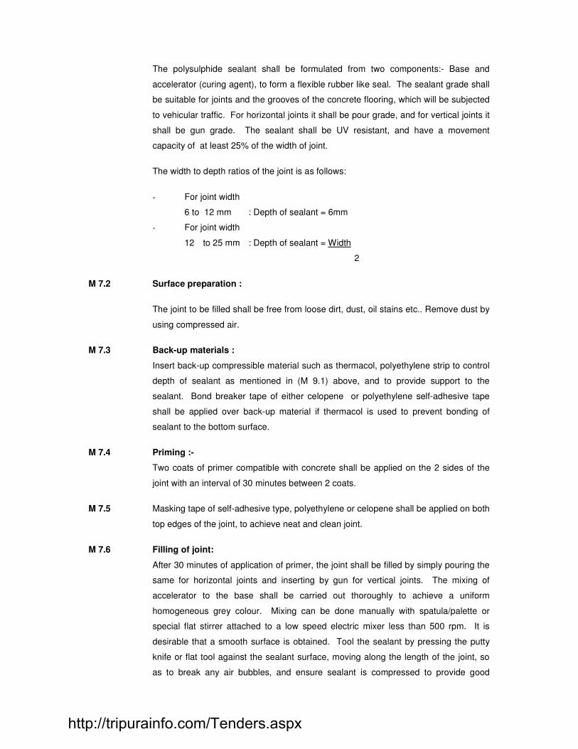
The polysulphide sealant shall be formulated from two components:- Base and
accelerator (curing agent), to form a flexible rubber like seal. The sealant grade shall
be suitable for joints and the grooves of the concrete flooring, which will be subjected
to vehicular traffic. For horizontal joints it shall be pour grade, and for vertical joints it
shall be gun grade. The sealant shall be UV resistant, and have a movement
capacity of at least 25% of the width of joint.
The width to depth ratios of the joint is as follows:
- For joint width
6 to 12 mm : Depth of sealant = 6mm
- For joint width
12 to 25 mm : Depth of sealant = Width
2
M 7.2 Surface preparation :
The joint to be filled shall be free from loose dirt, dust, oil stains etc.. Remove dust by
using compressed air.
M 7.3 Back-up materials :
Insert back-up compressible material such as thermacol, polyethylene strip to control
depth of sealant as mentioned in (M 9.1) above, and to provide support to the
sealant. Bond breaker tape of either celopene or polyethylene self-adhesive tape
shall be applied over back-up material if thermacol is used to prevent bonding of
sealant to the bottom surface.
M 7.4 Priming :-
Two coats of primer compatible with concrete shall be applied on the 2 sides of the
joint with an interval of 30 minutes between 2 coats.
M 7.5 Masking tape of self-adhesive type, polyethylene or celopene shall be applied on both
top edges of the joint, to achieve neat and clean joint.
M 7.6 Filling of joint:
After 30 minutes of application of primer, the joint shall be filled by simply pouring the
same for horizontal joints and inserting by gun for vertical joints. The mixing of
accelerator to the base shall be carried out thoroughly to achieve a uniform
homogeneous grey colour. Mixing can be done manually with spatula/palette or
special flat stirrer attached to a low speed electric mixer less than 500 rpm. It is
desirable that a smooth surface is obtained. Tool the sealant by pressing the putty
knife or flat tool against the sealant surface, moving along the length of the joint, so
as to break any air bubbles, and ensure sealant is compressed to provide good
http://tripurainfo.com/Tenders.aspx

adhesion to the joint sides. After tooling the masking tape should be removed
immediately. Soap solution can be used to smoothen the sealant surface.
MODE OF MEASUREMENT:
The item shall be paid on a linear basis RM (running meter) for specified sealant size
in specified joint size, including all primer, back-up material, bond breaker tape,
masking tape, etc complete.
M.9 SPECIFICATION NOMENCLATURE OF SUPER THERMOLAY POLYMER MODIFIED
POLYSTER REINFORCED MEMBRANE FOR WATERPROOFING
Providing and laying SUPER THERMOLAY - Torchseal polymer modified Torch-on
Membrane waterproofing system (1mx10mx4mm) make, having a thickness of 4mm/3mm
non oven polyester carrier of 140gm/sq.m sandwitched between two layers of APP Polymer
modified bitumen and both side covered with thermofusible polyethlene film. The membrane
will have a softening point above 140 degree C and UV established stabilised to 2,000 hours
(equivalent to ten years exposure). The membrane is laid on a properly graded roof in the
following manner:
- Make the surface smooth even and free from local depression, loose dirt, etc.
- Prime the dried surface with bituminous primer at the rate of 0.25 litre/m2.
- Providing one coat of special grade modified bitumen at the rate of 1.2kg/sq.m.
- Laying of SUPER THERMOLAY - Torchseal 4B by torching with a pressure regulated gas
on the above.
- Providing with one coat of special grade bitumen on the surface of the above membrane at
the rate of 1.0kg/m2.
- The overlapping to be done upto 4 inch at the overlapping joints, the bottom side of the top
sheet is to be torch applied and to be loaded to the bottom sheet to make it as per drawings.
The drain, parapets, etc to be treated as per drawing to make it sealproof and as per
instruction of Engineers at site.
http://tripurainfo.com/Tenders.aspx

SECTION - N
ROOFING & SKYLIGHT
A) Supply of Double skin LYSAGHT roofing/cladding system with Top & Bottom sheet is trapezoidal TRIMDEK profile sheet of 1015 mm effective cover width and nominal 28.3 mm deep ribs with subtle square fluting in the five pan at nominal 203 mm and centre-to-centre. The feed material for both Top & Bottom sheet is manufactured out 0.45 mm Base Metal Thickness (BMT), (0.50 mm TCT, Color coating Thickness is over and above the thickness stated above),Hi-Tensile steel with min. 550 MPa yield strength, metallic hot dip coated with Zinc/Aluminium alloy (55% Aluminium, 45% Zinc) as per AS 1397 - Zincalume AZ150 (min. 150 gms/sq.mt total on both sides) with Colorbond steel quality paint coat as per AS/NZS 2728 Class 3 of Tata BlueScope Steel make .The paint shall have a total coating thickness of nominal 35 μm, comprising of nominal 20 μm exterior coat on top surface and nominal 5 μm reverse coat on back surface over nominal 5 μm primer coat on both surfaces of approved colour shade for the top & Bottom sheet by the concern authority. The sheet shall have brand marking of the manufacturer giving product details on the back of the sheet at every regular interval for confirming genuinity of the material. The fastener size shall be calculated as per the design for the top and bottom sheet. The sheets shall sandwich a Glass Wool insulation layer with (24kg/m
3 Density) insulation of 50 mm thickness with Single side Aluminum Foil
facing.
GI Spacer channel / sub girt shall per provided between the Top & Bottom Sheet .as per the design required and as recommended by the manufacturer. The entire Double skin system is installed over the structure purlin.
B) POLYCORBONATE SKYLIGHT
http://tripurainfo.com/Tenders.aspx

1. The work of skylight shall be carried out only by an approved Contractor who has
executed this type of work.
Shop drawings shown aluminium section and fixing detail for Polycarbonate sheets shall
be submitted for approval.
2. G.I. Structural supports shall be fabricated by the Contractor for skylight to minimize any
mismatch.
3. The cross section of the specially fabricated aluminium member shall conform to profile
GE 104 & 105 OF GE plastic India Catalogue or equivalent. Aluminium allow for the
profile shall conform to IS 285. The mechanical properties of Aluminium section shall
conform to that of designated number 63400 in the above standard.
All aluminium section shall be with anodizing coating of 20 micron of approved shade.
4. the fixing detail shall generally follow manufacturers fixing details : Approved treatment
shall be given to avoid galvanic corrosion between aluminium and steel members.
5. Laxan Polycarbonate sheets of embossed type (figured sheets) shall be used. Sheets
shall be designated for wind pressure conforming to IS 875. External side of
Polycarbonate sheets shall have UV protection. Sample of polycarbonate sheets shall be
tested to confirm that the quality of sheets conforms to specification of manufacturers.
Allowance of the thermal expansion shall be made.
Sealing of the joint between the aluminium and Polycarbonate sheets (top and bottom of
sheets) shall be made with EPDM neoprene gaskets of approved make.
In addition to the above, Polycarbonate sheets shall also be fixed to cross supporting
members, with very high bond, double sided adhesive tape, 12 mm wide x 0.3 mm thick
Birla 3 M. brand or other approved make. The spacing of 6.5 mm dia brass screws,
connecting aluminium sections 105 & 104, length, shall be to suit the design pressure and
it shall not be more than 300 mm. The junction between the washer, and nut and between
washer and top of aluminium section sheet shall be treated with neutral Silicone sealant
of approved make.
Mode of Measurement of Payment :
http://tripurainfo.com/Tenders.aspx

Method of measurement and payment shall be as follows :
Structural tubular Steel : Actual weight as per approved drawings shall be measured
and paid per M.T. of steel, as per Section – A.
Polycarbonate sheets : Actual area of Polycarbonate sheets of specified thickness
used in the work shall be measured and paid on square metre basis. The rate shall
include the wastage in cutting sheets to the required profile.
Aluminium Section : Actual weight including as per approved drawing shall be
measured and paid on weight basis, per MT of Aluminium Section only. The rate shall
include the cost of anodizing. EPDM neoprene gasket, clamping plate and Silicone
sealant and screws.
Aluminium flashing of specified thickness shall be measured and paid on weight basis.
SECTION – R ROAD WORKS
http://tripurainfo.com/Tenders.aspx
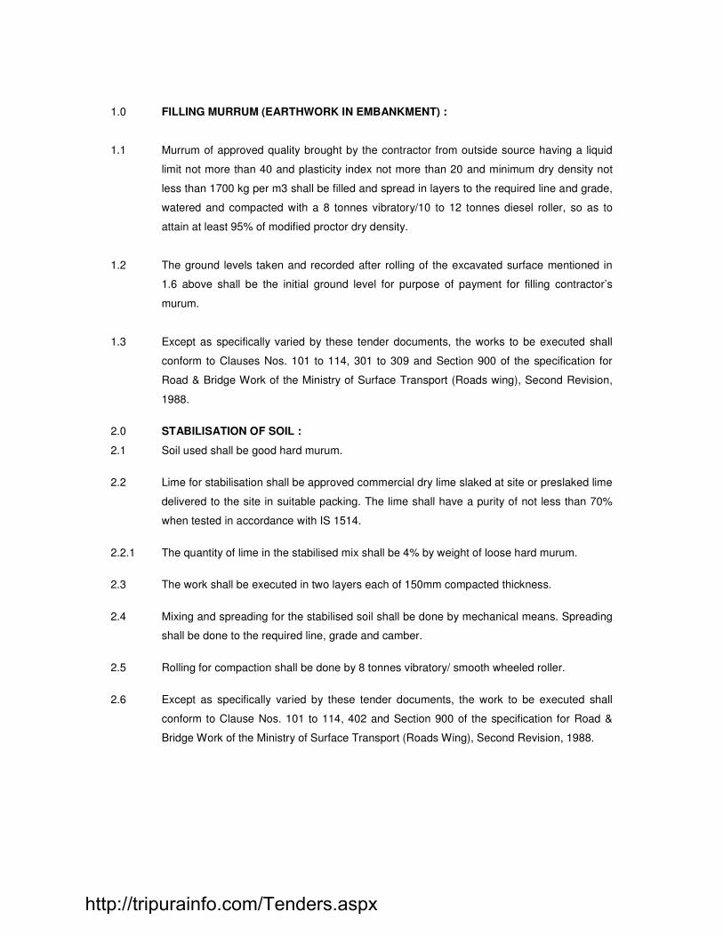
1.0 FILLING MURRUM (EARTHWORK IN EMBANKMENT) :
1.1 Murrum of approved quality brought by the contractor from outside source having a liquid
limit not more than 40 and plasticity index not more than 20 and minimum dry density not
less than 1700 kg per m3 shall be filled and spread in layers to the required line and grade,
watered and compacted with a 8 tonnes vibratory/10 to 12 tonnes diesel roller, so as to
attain at least 95% of modified proctor dry density.
1.2 The ground levels taken and recorded after rolling of the excavated surface mentioned in
1.6 above shall be the initial ground level for purpose of payment for filling contractor’s
murum.
1.3 Except as specifically varied by these tender documents, the works to be executed shall
conform to Clauses Nos. 101 to 114, 301 to 309 and Section 900 of the specification for
Road & Bridge Work of the Ministry of Surface Transport (Roads wing), Second Revision,
1988.
2.0 STABILISATION OF SOIL :
2.1 Soil used shall be good hard murum.
2.2 Lime for stabilisation shall be approved commercial dry lime slaked at site or preslaked lime
delivered to the site in suitable packing. The lime shall have a purity of not less than 70%
when tested in accordance with IS 1514.
2.2.1 The quantity of lime in the stabilised mix shall be 4% by weight of loose hard murum.
2.3 The work shall be executed in two layers each of 150mm compacted thickness.
2.4 Mixing and spreading for the stabilised soil shall be done by mechanical means. Spreading
shall be done to the required line, grade and camber.
2.5 Rolling for compaction shall be done by 8 tonnes vibratory/ smooth wheeled roller.
2.6 Except as specifically varied by these tender documents, the work to be executed shall
conform to Clause Nos. 101 to 114, 402 and Section 900 of the specification for Road &
Bridge Work of the Ministry of Surface Transport (Roads Wing), Second Revision, 1988.
http://tripurainfo.com/Tenders.aspx

3.0 GRANULAR SUB-BASE
3.0.1 Scope This work shall consist of laying and compacting well-graded material on prepared
subgrade in accordance with the requirements of these Specifications. The material
shall be laid in one or more layers as sub-base or lower sub-base and upper sub-
base (termed as sub-base hereinafter) as necessary according to lines, grades and
cross-sections shown on the drawings or as directed by the Engineer.
3.0.2 Materials
3.0.2.1 The material to be used for the work shall be natural sand, moorum, gravel, crushed
stone, Jhama brick aggregate or combination thereof depending upon the grading
required. Materials like crushed slag, crushed concrete, brick metal and kankar may
be allowed only with the specific approval of the Engineer. The material shall be
free from organic or other deleterious constituents and conform to one of the
three grading given in Table 3.4.
3.0.2.2 While the gradings in Table 3.4 are in respect of close-graded granular sub-base
materials, one each for maximum particle size of 75 mm, 53 mm and 26.5 mm.
3.0.2.3 Physical requirements: The material shall have a 10 per cent fines value of 50 kN or
more (for sample in soaked condition) when tested in compliance with BS: 812 (Part
111). The water absorption value of the coarse aggregate shall be determined as per
IS: 2386 (Part 3); if this value is greater than 2 per cent, the soundness test shall be
carried out on the material delivered to site as per IS: 383. For Grading II and III
materials, the CBR shall be determined at the density and moisture content likely to
be developed in equilibrium conditions which shall be taken as being the density
relating to a uniform air voids content of 5 per cent.
TABLE 3.4: Grading for Close-Graded Granular Sub-Base Materials
IS Sieve Designation
Per cent by weight passing the IS sieve
Grading I Grading II Grading III
75.0 mm 100 - -
53.0 mm 80–100 100 -
26.5 mm 55-90 70-100 100
9.50 mm 35-65 50-80 65-95
4.75 mm 25-55 40-65 50-80
2.36 mm 20-40 30-50 40-65
0.425 mm 10–25 15–25 20–35
0.075 mm 3-10 3-10 3-10
CBR value (Minimum)
30 25 20
http://tripurainfo.com/Tenders.aspx

3.0.3 Strength of sub-base
It shall be ensured prior to actual execution that the material to be used in the sub-
base satisfies the requirements of CBR and other physical requirements when
compacted and finished.
When directed by the Engineer, this shall be verified by performing CBR tests in the
laboratory as required on specimens remoulded at field dry density and moisture
content any other tests for the “quality” of materials, as may be necessary.
3.0.4 Construction Operations
3.0.4.1 Preparation of subgrade: Immediately prior to the laying of sub-base, the subgrade
already finished to Clause 3.1 shall be prepared by removing all vegetation and other
extraneous matter, lightly sprinkled with water if necessary and rolled with two
passes of 80 – 100 kN smooth wheeled roller.
3.0.4.2 Spreading and Compacting: The sub-base material of grading specified in the
Contract shall be spread on the prepared subgrade with the help of a motor grader of
adequate capacity, its blade having hydraulic controls suitable for initial adjustment
and for maintaining the required slope and grade during the operation or other means
as approved by the Engineer.
When the sub-base material consists of combination of materials mentioned in
Clause 3.3.2, mixing shall be done mechanically by the mix-in-place method.
Manual mixing shall be permitted only where the width of laying is not adequate for
mechanical operations, as in small-sized jobs. The equipment used for mix-in-place
construction shall be a rotavator or similar approved equipment capable of mixing the
material to the desired degree. If so desired by the Engineer, trial runs with the
equipment shall be carried out to establish its suitability for the work.
Moisture content of the loose material shall be checked in accordance with IS: 2720
(Part 2) and suitably adjusted by sprinkling additional water from a truck mounted or
trailer mounted water tank and suitable for applying water uniformly and at controlled
quantities to variable widths of surface or other means approved by the Engineer so
that, at the time of compaction, it is from 1 per cent above to 2 per cent below the
optimum moisture content corresponding to IS: 2720 (Part 8). While adding water,
due allowance shall be made for evaporation losses. After water has been added, the
material shall be processed by mechanical or other approved means like disc
harrows, rotavators until the layer is uniformly wet.
Immediately thereafter, rolling shall start. If the thickness of the compacted layer does
not exceed 100 mm, a smooth wheeled roller of 80 to 100 kN weight may be used.
For a compacted single layer upto 225 mm the compaction shall be done with the
help of a vibratory roller of minimum 80 to 100 kN static weight with plain drum or pad
foot-drum or heavy pneumatic tyred roller of minimum 200 to 300 kN weight having a
http://tripurainfo.com/Tenders.aspx

minimum tyre pressure of 0.7 MN/m2 or equivalent capacity roller capable of
achieving the required compaction. Rolling shall commence at the lower edge and
proceed towards the upper edge longitudinally for stretches of unidirectional crossfall
and super-elevation, and shall commence at the edges and progress towards the
centre for stretches having crossfall on both sides.
Each pass of the roller shall uniformly overlap not less than one-third of the track
made in the preceding pass. During rolling, the grade and crossfall (camber) shall be
checked and any high spots or depressions, which become apparent, corrected by
removing or adding fresh material. The speed of the roller shall not exceed 5 km per
hour.
Rolling shall be continued till the density achieved is at least 98 per cent of the
maximum dry density for the material determined as per IS: 2720 (Part 8). The
surface of any layer of material on completion of compaction shall be well closed, free
from movement under compaction equipment and from compaction planes, ridges,
cracks or loose material. All loose, segregated or otherwise defective areas shall be
made good to the full thickness of layer and re-compacted.
3.0.5 Surface Finish and Quality Control of Work
The surface finish of construction shall conform to the requirements of Clause 3.15.
Control on the quality of materials and works shall be exercised by the Engineer in
accordance with Section 3.15.
3.0.6 Arrangements for Traffic
During the period of construction, arrangement of traffic diversions shall be
maintained as per the direction of Engineer.
3.0.7 Measurements for Payment
Granular sub-base shall be measured as finished work in position in cubic metres.
The protection of edges of granular sub-base extended over the full formation as
shown in the drawing shall be considered incidental to the work of providing granular
sub-base and as such no extra payment shall be made for the same.
3.0.8 Rate
The Contract unit rate for granular sub-base shall be payment in full for carrying out
the required operations including full compensation for:
(i) making arrangements for traffic diversions. Except for initial treatment to
verges, shoulders and construction of diversions;
(ii) furnishing all materials to be incorporated in the work including all royalities,
fees, rents where necessary and all leads and lifts;
http://tripurainfo.com/Tenders.aspx

(iii) all labour, tools, equipment and incidentals to complete the work to the
Specifications;
(iv) carrying out the work in part widths of road where directed;
(v) carrying out the required tests for quality control and
(vi) multiple handling of materials
http://tripurainfo.com/Tenders.aspx

INTERLOCKING BLOCKS 4.0 Interlocking block :
4.1.1 Scope :
Scope of work consisting of manufacturing of concrete paver blocks of required size,
shape and colour . i.e. I – shape/ unipaver as per the specification given below and
supplying and fixing of the blocks on walkway.
4.1.2 Dimensions and Tolerances :
Concrete interlocking paver blocks shall be made in size and shall be as specified in the
tender document.
Maximum variation in dimension and Interlocking block shall not be more than +/- 2mm.
4.1.3 Cement & Sand Specification same as per relevant section
4.1.4 Coarse Aggregates :
4.1.4.1 Coarse aggregates for the works shall be river gravel or crushed stone conforming to IS :
383 obtained from sources approved by the Engineer.
Aggregates shall be properly screened and if necessary washed and cleaned at the
Contractor's cost before use. The coarse aggregates containing flat or flaky pieces or
mica shall be rejected.
4.1.4.2 Prior to deciding on the source for procurement of constituents of concrete viz. fine and
coarse aggregate the contractor shall specifically assess the soluble chloride and
sulphate contents of fine and coarse aggregates (at source) and their permissible limit
shall be approved by Engineer. Regular checks as directed, shall also be carried out, not
only at the source of supply of such materials, but also prior to mixing. The material shall
not contain impurities exceeding the permissible limits. The various limits permissible for
fine and coarse aggregates shall be given as below.
Sr. No. Requirement of aggregate Fine Coarse
a. Chloride Content (Cl) 0.04% of wt. (Acid soluble)
0.2% of wt. (Acid soluble)
b. Sulphate content (S 03) max 0.04% of wt.
(Acid soluble) 0.04% of wt. (Acid soluble)
c. Potential alkali reactivity Absent Absent
d. Water absorption max. less than 75 microns
2% by wt. 2% by wt.
e. Particles of size 3% by wt. 2% by wt. f. Sand equivalent more than 35% ---
http://tripurainfo.com/Tenders.aspx
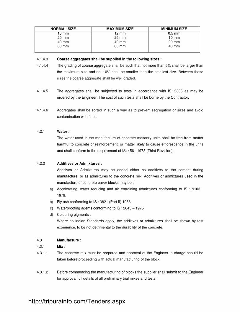
NORMAL SIZE MAXIMUM SIZE MINIMUM SIZE
10 mm 12 mm 0.5 mm 20 mm 25 mm 10 mm 40 mm 40 mm 20 mm 80 mm 80 mm 40 mm
4.1.4.3 Coarse aggregates shall be supplied in the following sizes :
4.1.4.4 The grading of coarse aggregate shall be such that not more than 5% shall be larger than
the maximum size and not 10% shall be smaller than the smallest size. Between these
sizes the coarse aggregate shall be well graded.
4.1.4.5 The aggregates shall be subjected to tests in accordance with IS: 2386 as may be
ordered by the Engineer. The cost of such tests shall be borne by the Contractor.
4.1.4.6 Aggregates shall be sorted in such a way as to prevent segregation or sizes and avoid
contamination with fines.
4.2.1 Water :
The water used in the manufacture of concrete masonry units shall be free from matter
harmful to concrete or reinforcement, or matter likely to cause efflorescence in the units
and shall conform to the requirement of IS: 456 - 1978 (Third Revision) .
4.2.2 Additives or Admixtures :
Additives or Admixtures may be added either as additives to the cement during
manufacture, or as admixtures to the concrete mix. Additives or admixtures used in the
manufacture of concrete paver blocks may be :
a) Accelerating, water reducing and air entraining admixtures conforming to IS : 9103 -
1979.
b) Fly ash conforming to IS : 3821 (Part II) 1966.
c) Waterproofing agents conforming to IS : 2645 – 1975
d) Colouring pigments .
Where no Indian Standards apply, the additives or admixtures shall be shown by test
experience, to be not detrimental to the durability of the concrete.
4.3 Manufacture :
4.3.1 Mix :
4.3.1.1 The concrete mix must be prepared and approval of the Engineer in charge should be
taken before proceeding with actual manufacturing of the block.
4.3.1.2 Before commencing the manufacturing of blocks the supplier shall submit to the Engineer
for approval full details of all preliminary trial mixes and tests.
http://tripurainfo.com/Tenders.aspx

4.3.1.3 when the proportions of a concrete mix have been approved by the Engineer, the
contractor shall not vary quality or source of materials or the mix without written approval
of the Engineer.
4.3.1.4 In case of blocks, where compaction is done by external vibrator, concrete mix very low
consistency (zero slump) shall be used in order to vibrate and compact the concrete
under pressure.
4.3.2 Mixing :
4.3.2.1 Concrete shall normally be mixed in a mechanical mixer.
4.3.2.2 Mixing shall be continued until there is a uniform distribution of materials, and the mass is
uniform in colour and consistency.
4.4 Placing and compaction :
4.4.1 The mould will be compacted by means of mechanical compaction. The mould shall be
filled up to overflow vibrated or mechanically tamped and struck off level.
4.4.2 After demoulding the blocks shall be protected until they are sufficiently hardened to
permit handling without damage.
4.5 Curing :
4.5.1 The blocks hardened in accordance with 1.4.2 shall then be cured in a curing water or in
a curing yard and shall be continuously moist for atleast 14 days. When the blocks are
cured in immersion tank, the water of the tank shall be changed at least every 4 days.
4.5.2 Steam curing of blocks hardened in accordance with 1.4.2. may be adopted instead of
methods specified in provided the requirements of pressure or non - pressure steam
curing are fulfilled.
4.6 Drying :
After curing the blocks shall be dried for a period of 4 weeks before being used on the
work. They shall be stacked with voids horizontal to facilitate through passage of air. The
blocks shall be allowed to complete their initial shrinkage before they are laid in a wall.
4.7 Surface Texture and Finish :
4.7.1 The finished concrete paver blocks shall have uniform texture and finish. The colour
pigment shall be approved by the Engineer in charge. The colour pigment shall be a non
fading and shall not have any deleterious effect on the concrete.
http://tripurainfo.com/Tenders.aspx
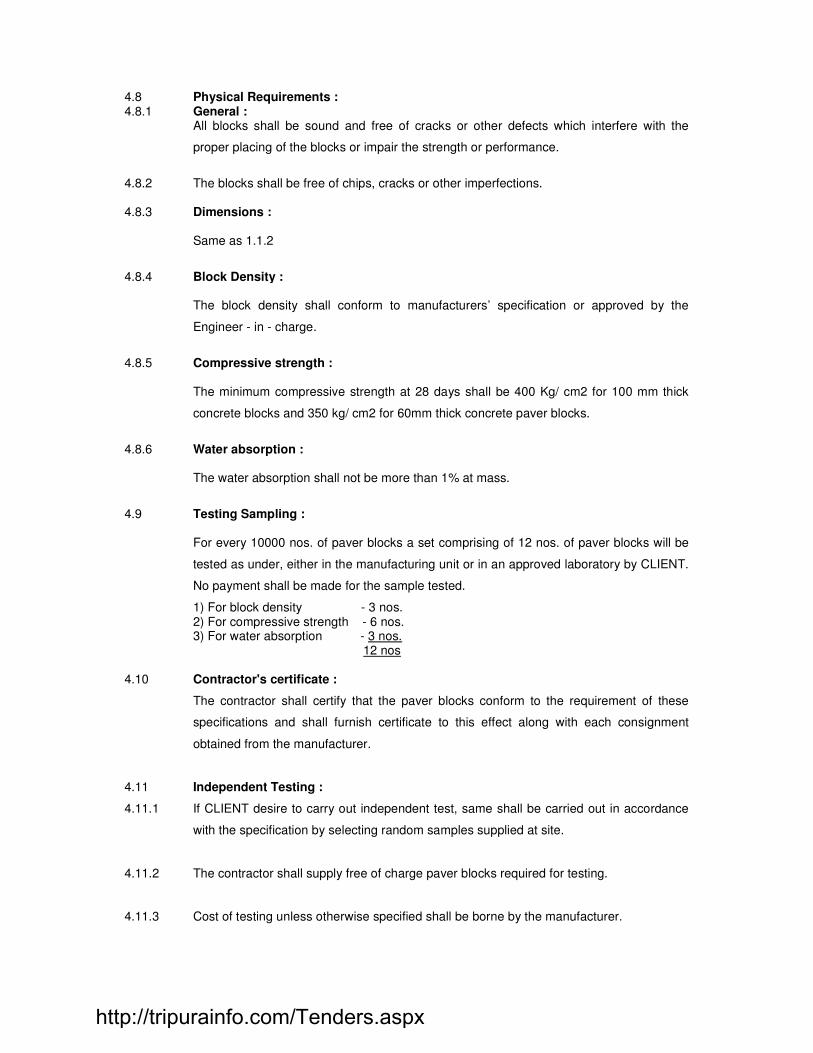
4.8 Physical Requirements : 4.8.1 General : All blocks shall be sound and free of cracks or other defects which interfere with the
proper placing of the blocks or impair the strength or performance.
4.8.2 The blocks shall be free of chips, cracks or other imperfections. 4.8.3 Dimensions :
Same as 1.1.2
4.8.4 Block Density :
The block density shall conform to manufacturers’ specification or approved by the
Engineer - in - charge.
4.8.5 Compressive strength :
The minimum compressive strength at 28 days shall be 400 Kg/ cm2 for 100 mm thick
concrete blocks and 350 kg/ cm2 for 60mm thick concrete paver blocks.
4.8.6 Water absorption :
The water absorption shall not be more than 1% at mass.
4.9 Testing Sampling :
For every 10000 nos. of paver blocks a set comprising of 12 nos. of paver blocks will be
tested as under, either in the manufacturing unit or in an approved laboratory by CLIENT.
No payment shall be made for the sample tested.
1) For block density - 3 nos. 2) For compressive strength - 6 nos. 3) For water absorption - 3 nos.
12 nos 4.10 Contractor's certificate :
The contractor shall certify that the paver blocks conform to the requirement of these
specifications and shall furnish certificate to this effect along with each consignment
obtained from the manufacturer.
4.11 Independent Testing :
4.11.1 If CLIENT desire to carry out independent test, same shall be carried out in accordance
with the specification by selecting random samples supplied at site.
4.11.2 The contractor shall supply free of charge paver blocks required for testing.
4.11.3 Cost of testing unless otherwise specified shall be borne by the manufacturer.
http://tripurainfo.com/Tenders.aspx

4.12 Laying and fixing Paver Blocks :
The interlocking paver blocks are to be fixed as indicated in the item description. The
ground is to be levelled taking into consideration the thickness of the paver blocks by part
excavation part filling and properly compacting using a plate compactor. Sand bed of
50mm is to be provided underneath the paver blocks after leveling the ground as base for
fixing the interlocking blocks. These concrete blocks should be placed as per design and
shape, as directed by the Engineer in charge. After laying the concrete blocks, fine sand
is to be spread over the paver block. The surface should be compacted using plate
compactor, so that the fine sand will get filled up in the gaps between blocks and the
block will be interlocked.
4.13 Cement Concrete Shot Blasted Tiles of size (Sizes : 250 x 250 x 24mm, 300 x 300 x 28mm, 400 x 400 x 31mm, 500 x 500 x 32mm)
Supply of High Strength and high wear resistant Cement Concrete Shot Blasted Tiles with – - wear resistant aggregates colour coordinated aggregates in face mix - Colours specified by the architects, using UV resistant colour Pigments from Lanxess. - (optional – Recommended) Two Coats of Acrylic Lacquer coating
Parameters Minimum Requirements (Testing as per IS 1237:1980)
1 Percentage Water Absorption Not over 7.5%
2 Wet transverse strength Not less than 5.5N/mm2
3 Average wear in Thickness-Abrasion Average wear not more than 2mm
4 Size (length + breadth) < 0.5mm
5 Thickness of wearing layer Not less than 8mm
6 Variation in Thickness of tiles Variation not to exceed 3mm
7 Flatness of tile surface Concavity / convexity not to exceed 0.5mm
8 Colours UV Light resistant fast colours from BAYFERROX only to be used min 3% to be used.
• The manufacturing company must be an ISO 9001:2000 certified Company or should have equivalent quality management systems in place to ensure quality product.
• The Terrazzo tiles must confirm to IS 1237:1980
• The tiles must be manufactured on automatic machines with mechanical vibration and rubberized moulds.
• The tiles must be ground on Linear Grinding Machine.
• The tiles will be made using wear resistant materials in the face mix as specified by the architects.
• The tiles must be cured in controlled environment to ensure efflorescence free material.
• The manufacture must have in house testing laboratory to carry out all testing including Compressive strength testing, Water absorption, abrasion resistance etc.
4.14 Cement Concrete Pebbled Terrazzo Tiles of size (Sizes: 300 x 300 x 32mm, 400 x 400 x 35mm) Supply of Customized “Pebblino” Series Terrazzo Tiles with special coloured pebble aggregates specified by Architects acrylic sealed finish.
Parameters Minimum Requirements (Testing as per IS 1237:1980)
1 Percentage Water Absorption Not over 7.5%
http://tripurainfo.com/Tenders.aspx

2 Wet transverse strength Not less than 5.5N/mm2
3 Average wear in Thickness-Abrasion Average wear not more than 2mm
4 Size (length + breadth) < 0.5mm
5 Thickness of wearing layer Not less than 8mm
6 Variation in Thickness of tiles Variation not to exceed 3mm
7 Flatness of tile surface Concavity / convexity not to exceed 0.5mm
8 Colours UV Light resistant fast colours from BAYFERROX only to be used min 3% to be used.
• The manufacturing company must be an ISO 9001:2000 certified Company or should have equivalent quality management systems in place to ensure quality product.
• The Terrazzo tiles must confirm to IS 1237:1980
• The tiles must be manufactured on automatic machines with mechanical vibration and rubberized moulds.
• The tiles will be made using wear resistant materials in the face mix as specified by the architects.
• The tiles must be cured in controlled environment to ensure efflorescence free material.
• The manufacture must have in house testing laboratory to carry out all testing including Compressive strength testing, Water absorption, abrasion resistance etc.
Shot blasted Concrete Cobbles Supply of Shot Blasted Type Solid Concrete Cobbles in colours specified by the architects, of VYARA make, using UV resistant Pigments from Lanxess and Wear resistant colour coordinated aggregates, with 2 coats of acrylic coating. Size 97x98x60mm thick. Nominal size of 100mm x 100mm
Parameters Minimum Requirements
1 Percentage water absorption Average not over 4.5%
2 Compressive strength Average not less than 250KG/cm2
3 Average wear in thickness-abrasion Average wear not more than 2mm
4 Tolerance in size (length + breadth) +/- 1.5mm
5 Thickness of wearing layer Not less than 5mm
6 Tolerance in Thickness of block +/- 3mm
7 Colours UV Light resistant fast colours from BAYFERROX only to be used min 3% to be used.
• The blocks must be manufactured on vibropress type machine only. The manufacture must demonstrate feeding of material into the machines by automatic batching plants with capacity of min 30 m3/hr.
4.15 Gabions
Gabbions should be factory fabricated boxes made of double twisted hexagonal
Wire mesh .additional protection to the wires is obtained by .5mm thickness of
Pvc coating over galvanized wires.
Pvc coating properties shall be as follows.
a) specific gravity : 1.3 to 1.35
b) tensile strength not less than : 20.6 mpa
c) modulus of elasticity not less than : 18.6 mpa
d) hardness between 50 to 60 shores
e) brittleness temperature : ASTM 2240
f) abrasion resistance : ASTM D1242
http://tripurainfo.com/Tenders.aspx

g) salt spray : ASTM B117
h) ultra violet ray : ASTM D1499 & G23
i) Appearance : PVC coating shall not crack
Gabbion boxes tolerances shal be confirming to ASTM A975
Diaphgram to be provided at every 1.0meter.
Wire properties shall be as per EN10223 & EN 10224.2
Wire shall be coated with zinc.
Twisted wire mesh shall be used. Mesh type may be 10x12 or 8x10
Gabbions shall be filled with stones and shall be installed as per installation guide of manufacturer.
4.16 Geo reinforcements 4.16.1 Geo-fabric
1. The reinforcing element shall be a geogrid manufactured in accordance with a Quality
Management System which complies with the requirements of BS EN ISO 9001:2000. If required
by the Engineer, the Contractor shall provide evidence that the manufacturer's Quality Assurance
System has been certified to conform with BS EN ISO 9001:2000 by an external authenticating
authority approved by the Department of Trade and Industry.
2. The reinforcing element shall be a geogrid manufactured from high density polyethylene sheet,
oriented in one direction so that the resulting ribs shall have a high degree of molecular
orientation which is continued through the integral transverse bar.
3. The creep limited tensile strength, for a design life of 120 years, shall be 23.4 kN/m at a mean
temperature of 30°C. This shall be determined by application of standard extrapolation
techniques to creep data obtained in accordance with BS EN ISO 13431:1999 and shall be a
lower bound value.
4. The geogrid shall have an appropriate partial factor for site installation and construction damage,
determined by the particle size distribution of the reinforced fill and in accordance with the values
used in the design. This factor shall be based on full scale tests carried out in accordance with
BS 8006:1995 Annex D and witnessed by an independent Approval Authority. If required by the
Engineer, the Contractor shall provide supporting documented evidence of testing for this and any
other partial factors assumed in the design.
5. The Quality Control Strength [expressed as the lower 95% confidence limit in accordance with
ISO 2602:1980 (BS 2846:Part 2:1981)] shall be 64.5 kN/m with a peak strain of around 11.5% at
that load when tested in accordance with BS EN ISO 10319:1996.
In addition, the load at 2% and 5% strains [expressed as the lower 95% confidence limit in
accordance with ISO 2602:1980 (BS 2846:Part 2:1981)] shall be 16.1 kN/m and 30.9 kN/m
respectively.
6. The strength of the junctions between the longitudinal ribs and transverse bars, as determined by
the Geosynthetics Research Institute, Drexel University, USA, Test Method GG2-87, shall be not
less than 100% of the Quality Control Strength.
http://tripurainfo.com/Tenders.aspx

7. The reinforcing element shall be the subject of a current and relevant Roads and Bridges
Agreement Certificate issued by the British Board of Agreement.
8. The minimum geogrid roll width shall be 1.3m.
9. Any site joints in the reinforcement roll length shall be capable of carrying in excess of 90% of the
geogrid Quality Control Strength when tested in accordance with BS EN ISO 10321:1996. If
required by the Engineer the Contractor shall carry out testing to demonstrate this.
The geogrid shall be inert to all chemicals naturally found in soils and shall have no solvents at
ambient temperature. It shall not be susceptible to hydrolysis, shall be resistant to aqueous solutions
of salts, acids and alkalis (pH = 2.0 to 12.5), shall be non-biodegradable and shall have a minimum of
2% finely divided carbon black, as determined by BS 2782:Part 4:Method 452B:1993, well dispersed
in the polymer matrix to inhibit attack by ultraviolet light.
4.16.2 Woven Geo Textile The individual multifilament yarns shall be woven together into a stable fabric structure with a
superior combination of mechanical and hydraulic properties. The product should have
excellent resistance to biological and chemical environments normally found in soils and is
stable against short-term exposure to ultraviolet radiation.
Woven Geotextile should be suitable for applications involving the functions of separation,
stabilization and filtration.
Woven Geotextile shall be conforms to the property values listed below, which have been derived
from tests carried out at reputed laboratories.
S.No Property Test Method Value (MARV)
I Polymer Composition, Structure and Physical Properties
1 Polymer Polypropylene
2 Structure Woven with multifilament yarn in both warp and weft directions
3 Mass per unit area ASTM D 3776 140 g/m2
4 Thickness 0.36
II Mechanical Properties
1 Tensile strength Warp
IS 1969
28 kN/m
Weft 26 kN/m
2 Elongation at designated peak tensile load
Warp 25 %
Weft 25 %
3 Trapezoid tearing strength Warp
ASTM D 4533 300 N
Weft 300 N
4 Puncture strength ASTM D 4833 250 N
III Hydraulic Properties
1 Apparent opening size ASTM D 4751 75 microns
2 Water flow rate normal to the plane ASTM D 4491 10 l/m2/s
http://tripurainfo.com/Tenders.aspx

1. The elongations reported are the actual fabric elongations at the designated peak tensile
load measured over a gauge length of 100 mm
Mode of Measurement:
The item shall be paid on m2 as unit, Excluding payment for laps, joints etc.
LIST OF APPROVED MATERIALS FOR CIVIL WORKS.
No. Material Make
1. Cement 53 Grade / 43 Grade Gujarat Ambuja, A.C.C., L&T, Rajashree / Birla
Super. Indorama slag cement, STAR, Topcem,
Crown, Valley Strong, Adhunik
2 Structural Steel Sail, Tisco, TATA
http://tripurainfo.com/Tenders.aspx

3. Mild & Tol Steel Sail, Tisco, Vizag, TATA
4. Plasticiser Sika, Sunanda Chemicals, Forsoc,
MC- Bauchemie
5. Waterproofing Compound Accorproof Impermo, Pediproof, CICO
6. Water Cement Paint, Quartz Reinforce
Paint
Super Snowcem, Nitocem.
7. Hardware Shalimar, Navbharat, Amarbhoy Dossaji
8. Glazing Hindustan Pilkington, Triveni, Float Glass of Modi,
AsahI India, Saint Goben, GSC.
9. Red Oxide Shalimar, Asian, Garware Paints.
10. Paints & Distempers Jenson & Nicholson, Burger Asian, ICI, Nerolac
11. Hardners Ironite, Ferrok, Hardnate.
12. Aluminium Doors, Windows, Partitions Etc. Jindal, Indal, Hindalco, Ajit India, Indian Aluminium
Sections or Equivalent
13 Rolling Shutters & Grills Standard Swastik, Shudhwar or equivalent ISI
Marked make
14 Aluminium Grills Aluminigrile, Deco or equivalent ISI Marked make
15 Vaccum Dewatering Equipment Tremix
16 Flush Door - I.S.I. Marked Anand Wood Crafts, M/s Shreeji Doors &
Plywood, "Timber Teck" Hyderabad,
Silvassa, Century, Green Ply or equivalent ISI
Marked make
17 Ceramic Tiles – 300 mm X 300 mm, 200 mm
X 300 mm
First Quality tile of Bell Ceramic, H&P, Jhonson,
Regancy, Navin Peddar, Kajaria, Somany, Orient.
18 White/ Coloured Glazed Tiles, First Quality Tiles of H&R Jhonson, Navin, Bell
19 Vitrified Tiles RAK, Bell granito, Naveen diamond tile, Euro, Pavit, Nitco, Somany, Orient.
http://tripurainfo.com/Tenders.aspx
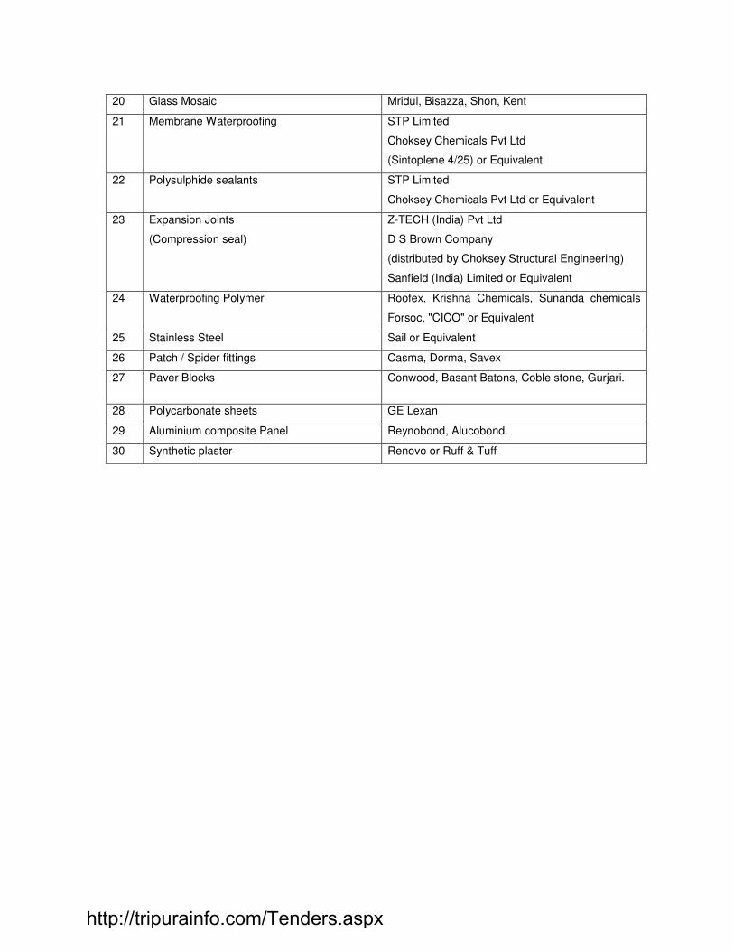
20 Glass Mosaic Mridul, Bisazza, Shon, Kent
21 Membrane Waterproofing STP Limited
Choksey Chemicals Pvt Ltd
(Sintoplene 4/25) or Equivalent
22 Polysulphide sealants STP Limited
Choksey Chemicals Pvt Ltd or Equivalent
23 Expansion Joints
(Compression seal)
Z-TECH (India) Pvt Ltd
D S Brown Company
(distributed by Choksey Structural Engineering)
Sanfield (India) Limited or Equivalent
24 Waterproofing Polymer Roofex, Krishna Chemicals, Sunanda chemicals
Forsoc, "CICO" or Equivalent
25 Stainless Steel Sail or Equivalent
26 Patch / Spider fittings Casma, Dorma, Savex
27 Paver Blocks Conwood, Basant Batons, Coble stone, Gurjari.
28 Polycarbonate sheets GE Lexan
29 Aluminium composite Panel Reynobond, Alucobond.
30 Synthetic plaster Renovo or Ruff & Tuff
http://tripurainfo.com/Tenders.aspx

1
SECTION II – PLUMBING WORKS
INDEX
SR. NO. TITLE PAGE NO.
1.0 GENERAL 3
2.0 APPLICABLE CODES & STANDARDS 3
3.0 QUALITY ASSURANCE & QUALITY CONTROL 4
4.0 SANITARY FIXTURES & C.P. FITTINGS 4
4.1 SCOPE 4
4.2 GENERAL REQUIREMENTS 5
4.3 EUROPEAN W.C. 5
4.4 KITCHEN / PANTRY SINKS 6
4.5 WASH BASINS 6
4.6 HOSE BIBB’S 6
4.7 URINALS 6
4.8 BATH TUB 6
4.9 MEASUREMENTS 7
5.0 WATER SUPPLY 7
5.1 SCOPE 7
5.2 GENERAL REQUIREMENTS 7
5.3 INTERNAL WORKS 8
5.4 EXTERNAL WORKS 11
5.5 VALVES 15
5.6 CHLORINATION OF DOMESTIC WATER LINES 17
5.7 CPVC PIPE & FITTINGS 17
5.8 COMPOSITE PIPE & FITTINGS 19
5.9 COPPER PIPES & FITTINGS 21
5.10 ASTM PVC PIPE & FITTINGS 22
5.11 PIPE HANDLING & STORAGE 23
5.12 LAYING & JOINTING 23
5.13 TESTING 24
6.0 INTERNAL DRAINAGE (SOIL, WASTE, VENT & RAIN WATER PIPES) 25
6.1 SCOPE 25
6.2 GENERAL REQUIREMENTS 25
6.3 CAST IRON PIPES & FITTINGS 25
http://tripurainfo.com/Tenders.aspx

2
SECTION II – PLUMBING WORKS
INDEX
SR. NO. TITLE PAGE NO.
6.4 SWR UPVC PIPES & FITTINGS 29
6.5 TRAPS 29
6.6 FLOOR TRAP INLET 29
6.7 C.P. / STAINLESS STEEL GRATING 30
6.8 CLEANOUT PLUGS 30
6.9 PIPE SLEEVES 30
7.0 EXTERNAL DRAINAGE SYSTEM (SEWERAGE & STORM WATER) 30
7.1 SCOPE 30
7.2 GENERAL REQUIREMENTS 30
7.3 TRENCHES FOR PIPE & DRAINAGE 30
7.4 RCC PIPES 32
7.5 STONE WARE PIPE 34
7.6 SEWER MANHOLES WITH FRAME AND COVER 38
7.7 DROP CONNECTIONS 41
8.0 EQUIPMENT SPECIFICATION 43
8.1 HYDROPNEUMATIC SYSTEM 43
8.1.1 SCOPE 43
8.1.2 CONSTRUCTION FEATURES 44
8.2 VALVES 45
8.3 TECHNICAL DATA SHEET FOR DOMESTIC WATER SUPPLY 47
8.4 CENTRIFUGAL PUMPS 50
8.5 GUN METAL GATE VALVE 52
8.6 GUN METAL NON RETURN VALVE 55
9.0 LIST OF APPROVED MAKES 59
http://tripurainfo.com/Tenders.aspx

3
GENERAL TECHNICAL SPECIFICATION FOR PLUMBING WORK
1.0 GENERAL: 1.1 The work shall be carried out in the accordance with the drawings and design as would be issued to the
Contractor by the Design Consultant duly signed and stamped by him. The Contractor shall not take cognizance of any drawings, designs, specifications etc. not bearing Design Consultant signature and stamp. Similarly the Contractor shall not take cognizance of instructions given by any other Authority except the instructions given by the Client’s Representative in writing.
1.2 The work shall be executed and measured as per metric dimensions given in the Bill of Quantities, drawings etc.
1.3 The Contractor shall acquaint himself fully with the partial provisions for supports that may or may not be available in the structure and if are available then utilize them to the extent possible. In any case the Contractor shall provide all the supports regardless of provisions that they have been already made. Nothing extra shall be payable for situations where insert plates (for supports) are not available or are not useful.
1.4 Shop coats of paint that may be damaged during shipment or erection shall be cleaned off with mineral spirits, wire brushed and spot primed over the affected areas, then coated with paint to match the finish over the adjoining shop painted surface.
1.5 The Contractor shall protect / handle the material carefully and if any damage occurs while handling by the Contractor then the sole responsibility shall be of the Contractor. Such damages shall be rectified/recovered by the Contractor at no extra cost whatsoever.
1.6 The Contractor shall, within twenty one (21) days of receipt of the Notice of Award for the Project,
where applicable, complete the submission of shop drawings to the Client’s Representative for approval by the Design Consultants in order to conform to the contract schedule.
1.7 MEASUREMENTS:
All measurements shall be taken in accordance with relevant IS codes, unless otherwise specified. 2.0 APPLICABLE CODES AND STANDARDS:
All equipment, supply, erection, testing and commissioning shall comply with the requirements of Indian Standards and code of practice given below as amended up to the date of submission of Tender. All equipment and material being supplied shall meet the requirements of BIS and other relevant standard and codes.
Plumbing Works:
Vitreous Chinaware - IS: 2556 - 1974 (Part - I)
- IS: 2556 - 1981 (Part - II)
- IS: 2556 - 2556 (Part - III)
Ball Valve - IS: 1703 - 1977
Cistern Brackets - IS: 775 - 1970
Toilet Seat Cover - IS: 2548 - 1983
Vitreous China Cistern - IS: 2326 - 1987
Sand Cast Iron Pipes and Fittings - IS: 1729 - 1979
Spun Cast Iron Pipes and Fittings - IS: 3989 - 1984
GI Pipes - IS: 1239 - 1979
Galvanizing for GI Pipes - IS: 4736 - 1986
Pipe Threads - IS: 554 - 1985
Milleable Iron Fittings - IS: 1879 - 1987
Cast Iron Sluice Valves - IS: 780 - 1984
Full Way Valves - IS: 778 - 1984
http://tripurainfo.com/Tenders.aspx

4
Brass Ferrule - IS: 2692 - 1978
Stone Ware Gully Trap - IS: 651 - 1980
RCC Pipes - IS: 458 - 1971
Cast Iron Class LA Pipes - IS: 1536 - 1989
Cast (Spun) Iron Fittings - IS: 1538 - 1976
Pig Lead - IS: 782 - 1966
Induction Motors - IS: 4691
Code for Measurements - IS: 1200
UPVC Pipes and Fittings - IS: 4984
Specification for Caulking Lead - IS: 782
Code of Practice for laying of concrete - IS: 783
3.0 QUALITY ASSURANCE AND QUALITY CONTROL: 3.1 The work shall conform to high standard of design and workmanship, shall be structurally sound and
aesthetically pleasing. Quality standards prescribed shall form the backbone for the quality assurance and quality control system.
3.2 At the site, the Contractor shall arrange the materials and their stacking/ storage in appropriate manner
to ensure the quality. Contractor shall provide equipment and manpower to test continuously the quality of material, assemblies etc. as directed by the Client’s Representative. The test shall be conducted continuously and the result of tests maintained. In addition the Contractor shall keep appropriate tools and equipment for checking alignments, levels, slopes and evenness of surface.
3.3 The Client’s Representative shall be free to carry out such tests as may be decided by him at this sole
direction, from time to time, in addition to those specified in this Document. The Contractor shall provide the samples and labour for collecting the samples. Nothing extra shall be payable to the Contractor for samples or for the collection of the samples.
3.4 The test shall be conducted at Standard Laboratory selected by Client’s Representative. Contractor
shall keep the necessary testing equipment such as hydraulic testing machine, smoke testing machine, gauges and other necessary equipment required.
3.5 The Client’s Representative shall transport the samples to the laboratory. 3.6 Testing charges shall be borne by the Client’s Representative. 3.7 Testing may be witnessed by the Contractor or his Authorised Representative. Whether witnessed by
the Contractor or not, the test results shall be binding on the Contractor.
4.0 SANITARY FIXTURES & C.P. FITTINGS:
4.1 SCOPE 4.1.1 Work under this section shall consist of transportation, furnishing, installation, testing and
commissioning and all labour as necessary as required to completely install all sanitary fixtures, brass and chromium plated fittings and accessories as required by the drawings and specified hereinafter or given in the Bill of Quantities.
4.2 GENERAL REQUIREMENTS 4.2.1 All fixtures and fittings shall be fixed with all such accessories as are required to complete the item in
working condition whether specifically mentioned or not in the Bill of Quantities, specifications, drawings or not.
4.2.2 All fixtures and accessories shall be fixed in accordance with a set pattern matching the tiles or interior
finish as per architectural design requirements. Wherever necessary the fittings shall be centered to dimensions and pattern desired.
http://tripurainfo.com/Tenders.aspx

5
4.2.3 Fixing screws shall be half round head chromium plated brass with C.P. washers wherever required as per directions of Client’s Representative.
4.2.4 All fittings and fixtures shall be fixed in a neat workmanlike manner true to levels and heights shows on
the drawings & in accordance with the manufacturer’s recommendations. Care shall be taken to fix all inlet and outlet pipes at correct positions. Faulty locations shall be made good and any damage to the finished floor, wall or ceiling surfaces shall be made good at Contractors cost.
4.2.5 All fixtures of the similar materials shall be by the same manufacturers. 4.2.6 All fitting shall be of the chromium plated materials. 4.2.7 Without restricting to the generally of the foregoing the sanitary fixtures shall include all sanitary
fixtures, C.P. fittings and accessories etc. necessary and required for the building. 4.7.8 Whether specifically mentioned or not all fixtures and appliances shall be provided with approved fixing
devices, nuts, bolts, screws, and hangers as required. These supports shall have the necessary adjustment to allow for irregularities in the building area construction.
4.7.9 For the installation of the CP fittings, Teflon tape shall be used. 4.3 EUROPEAN W.C. 4.3.1 European W.C. of glazed vitreous china shall be wash down, single or double symphonic type, floor
or wall mounted set, flushed by means of flush valve as specified in Bill of Quantities. Flush pipe / bend shall be connected to the W.C. by means of suitable rubber adopter. Wall hung W.C. shall be supported by C.I. floor mounted chair.
4.3.2 Each W.C. seat cover shall be so fixed that it remains absolutely stationary in vertical position without
falling down on the W.C. Seat cover shall be of white solid plastic, elongated open front with heavy duty hinges. Exposed fixture trims shall be Chrome plated, and trims of similar function shall be by the same manufacturer.
4.3.3 Flush valves shall be of the best approved quality procurable with C.P. control valve and C.P. flush
pipe. 4.3.4 The flush pipe/bend shall be connected to the WC by means of a suitable rubber adopter. 4.3.5 Alternatively if flushing cistern to be used shall conform to the requirements of IS: 774-1971. High level
cisterns shall be of cast iron unless otherwise specified. Low level cistern shall be of the same material as the water closet or as instructed by the Owner/Architect/ Consultant. The cisterns shall be mosquito proof & shall fulfill the requirements of the local Authority.
4.3.6 The levels of the WC should be checked by placing sprit level on the W.C. W.C. should be tested on
completion of fixing by putting small paper balls and flushing out. If all the paper balls are not flushed out. The fixing will have to be rectified / re-aligned.
4.4 KITCHEN / PANTRY SINKS 4.4.1 Sinks shall be of stainless steel material as specified in the Bill of Quantities/Drawings. 4.4.2 Each sink shall be provided with R. S. brackets and clips and securely fixed. Counter top sinks shall be
fixed with suitable angle iron clips or brackets as recommended by the manufacturer. Each sink shall be provided with 40 mm dia Chromium Plated waste with chain and plug or P.V.C. waste with Escutcheon plates. Fixing shall be done as directed by Client’s Representative.
4.4.3 Supply fittings for sinks shall be mixing fittings or C.P. taps, angle cocks etc. all as specified in the Bill
of Quantities/Drawings. 4.5 WASH BASINS
http://tripurainfo.com/Tenders.aspx

6
4.5.1 Wash basin shall be of white vitreous china of best quality manufactured by an approved firm and sizes
as specified in the Bill of Quantities. 4.5.2 Wash basin shall be of under counter drop in type shall be supported on a pair of rolled steel brackets
of approved design and shall be mounted on a countertop. So that rim and basin bowl is exposed from top.
4.5.3 Wash basin shall be provided with single lever mixer with chain and rubber plug, chromium plated
brass bottle trap of approved quality, design and make where hot water required. Single tap where hot water is not required.
4.5.4 Wash basin shall be fixed at proper location and height and truly horizontal as shown on drawing or as
directed by Client’s Representative. 4.6 HOSE BIBB’S 4.6.1 Hose Bib of Chromium Plate tap is draw off tap with horizontal inlet and free outlet knurling on outer
face to fix the hose pipe. Hose bib shall be of specified size and shall be of screw down type and shall conform to IS: 781-1984. The closing device shall work by means of a disc carrying a renewable non-metallic washer which shuts against the water pressure on a seating at right angle to the axis of the threaded spindle which operate it. The handle shall be either crutch or butterfly type securely
4.7 URINALS Half stall wall hung urinals of glazed vitreous china shall be provided with 15mm dia, C.P. brass
spreader, 32mm dia C.P. domical waste and C.P. cast brass bottle trap with pipe and wall flange and shall fixed to wall by one C.I. bracket and two C.I. clips as recommended by manufacturers complete as directed by the Client’s Representative.
Urinals shall be flushed by means of “NO-TOUCH” infrared operated flush valves. Waste pipes for urinals shall be any one of the given material as directed by the Client’s
Representative:
a) G.I. Pipes
b) Rigid PVC/High density polyethylene.
Waste pipes may be exposed on wall or concealed in chase as directed by the Client’s Representative. 4.8 BATH TUB Bath tub & panel shall be white enameled cast iron or pressed steel as specified in the Bill of Quantities
of guaranteed quality and specifications. Each bath tub shall be provided with 40mm dia CP brass waste with 32mm C.P. brass overflow, 40mm
dia cast brass overflow-cum-waste trap with pop-up waste assembly. Bath tub shall be provided with four Nos. C.P. brass concealed stop cocks, bath spout and overhead
shower or as specified in the Bill of Quantities. Bath tubs shall be fixed true to level firmly fixed to another or supports provided by the manufacturer.
Edges touching the wall shall be slightly recessed in the wall finishing so as ensuring water tightness. The fixing shall be perfectly done so that the wall behind does not tend to get damp or patchy.
Contractor shall during the entire period of installation and afterwards protect the bathtub by providing
suitable cover or any other protection so as to absolutely prevent any damage to the bathtub until handing over.
4.9 MEASUREMENTS
4.9.1 Rate for providing and fixing of sanitary fixtures, accessories, urinal partitions shall include all items and operations stated in the respective specifications and Bill of Quantities, and nothing extra is payable.
http://tripurainfo.com/Tenders.aspx

7
4.9.2 Rates for all items under specifications para above shall be inclusive of cutting holes and chases and making good the same, C.P. screws, nuts, bolts and any fixing arrangement required.
5.0 WATER SUPPLY: 5.1 SCOPE 5.1.1 Work under this section consists of furnishing all labour, materials equipment and appliances necessary
and required to completely install the water supply system as required by the drawings, specified hereinafter and given in the bill of quantities.
5.1.2 Without restricting to the generality of the foregoing, the water supply system shall include the
following:-
i. Pipe protection & painting. ii. Connections to all plumbing fixtures, tanks, pump etc. iii. Providing hot water pipe lines and supply point with isolation valves, wherever required. iv. Control valves, masonry chambers and other appurtenances. v. Connections to all plumbing fixtures, tanks and appliances. vi. Excavation and refilling of pipe trenches, wherever necessary. vii. Internal galvanized water supply piping inside the toilets shaft/plant room/terrace. viii. Testing all line and fixtures as specified.
5.2 GENERAL REQUIREMENTS:
5.2.1 All materials shall be new of the best quality and shall be furnished, delivered, erected, connected and finished in every detail conforming to specifications and subject to the approval of Client’s Representative.
5.2.2 Pipes and fittings shall be fixed truly vertical, horizontal or in slopes as required in a neat workmanlike
manner.
5.2.3 Short or long bends shall be used on all main pipe lines as far as possible. Use of elbows shall be restricted for short connections.
As far as possible all bends shall be formed by means of hydraulic pipe bending machine for pipes up to 65mm dia.
5.2.4 Pipes shall be fixed in a manner as to provide easy accessibility for repair and maintenance and shall
not cause obstruction in shafts, passages etc. and shall be selected and arranged so as to fit properly into the allocated building space.
5.2.5 Pipes shall be securely fixed to walls by suitable clamps at intervals specified. 5.2.6 Valves and other appurtenances shall be located to provide easy accessibility for operation,
maintenance and repairs. 5.2.7 Connection between dissimilar materials. 5.2.8 All G.I. pipes jointing shall be with white lead and spun yarn. 5.2.9 Drawings illustrating block out and penetration of pipes in the wall/floor/slab. 5.2.10 UNIONS: Contractor shall provide adequate no. of unions on all pipes to enable dismantling later and for
servicing. Union shall be provided near each gunmetal valve.
http://tripurainfo.com/Tenders.aspx

8
5.3 INTERNAL WORKS 5.3.1 MATERIALS: 5.3.1.1 G.I. PIPES
i. The pipes shall be galvanised mild steel threaded pipes conforming to the requirement of IS: 1239 Part-I for heavy grade upto 150mm dia and IS: 3589 for pipes above 150mm dia. They shall be of the dia (nominal bore) specified in the description of the item. Galvanising shall confirm to IS: 4736.
ii. The pipes shall be clearly finished, well galvanised in and out and free from cracks, surface flow,
laminations and other defects. All screw threads shall be clean and well cut. The ends shall be cut cleanly and square with axis of the tube.
iii. All screw tubes shall have pipe threads conforming to the requirements of IS: 544-1955 (or
revised). 5.3.1.2 G.I. FITTINGS
i. All fittings shall be conforming to IS: 1239 Part II (or as revised). All fittings shall have
manufacturer's trade mark stamped on it. Fittings in G.I. pipe lines shall include elbows, tees, bends, reducers, nipples, union, G.I. Clamps / Steel structural supports of approved design, nuts, bolts, washers, etc. All fittings shall be tested at manufacturer's works. Contractors may be required to produce certificate to this effect from the manufacturers.
ii. The fittings shall have screw threads at the ends conforming to the requirements of IS: 544-1955
(or revised). Female threads on fittings shall be parallel and male threads (except on running nipples and collars of unions) shall be tapered.
5.3.1.3 CUTTING AND JOINTING:
i) The pipes and fittings shall be inspected at site before use to ascertain that they conform the specification given in para no. 5.3.1.1 above. The defective pipes shall be rejected. Where the pipes have to be cut or re-threaded, the ends shall be carefully filled out so that no obstruction to bore is offered. The end of the pipes shall then be threaded conforming to the requirements of IS: 544-1955 with pipe dies and taps carefully is such a manner as will not result in slackness of joints when the two pieces are screwed together. The taps and dies shall be used only for straightening screw threads which have become bend or damaged and shall not be used for turning of the threads so as to make them slack, as the later procedure may not result in water tight joint.
ii) The screw threads of pipes and fittings shall be protected from damage until they are fitted.
iii) The pipes shall be cleaned and cleared of all foreign matter before being laid. In jointing the pipes, the inside of the socket and the screwed end of the pipes shall be oiled and rubbed over with white lead and a few turns of spun yarn wrapped round the screwed end of the pipe. The end shall then be screwed in the socket. Care should be taken that all pipes and fitting are properly jointed so as to make the joints completely water tight and pipes are kept at all times free dust and dirt during the fixing. Burr from the joint shall be removed after laying. The open ends of the pipes shall be temporarily plugged to prevent access of water, solid or any other foreign matter.
5.3.2 INSTALLATION OF G.I.: Tender drawings indicate schematically the size and location of pipes. The Contractor on the award of
the work, shall prepare detailed coordinated with other trades working drawings, showing the cross-section, longitudinal sections, details of fittings, locations of isolating and control valves, drain valves and all pipe support, structural supports. He must keep in view the specific openings in buildings and other structures through which pipes are designed to pass.
i. Piping shall be properly supported on or suspended from connection clamps, hangers as specified
and as required. Install pipes in a manner to avoid strain on equipments connections. The Contractor shall adequately design all the brackets, saddles, anchors, clamps and hangers, and be responsible for their structural sufficiency.
ii. Pipe supports shall be of steel, adjustable for height and primer coated with rust preventive paint
http://tripurainfo.com/Tenders.aspx

9
and finish coated back. Where pipe and clamps are of dissimilar materials a dielectric fitting shall be provided in between. Spacing of pipe supports shall not exceed the following:
Pipe Size Spacing between Supports
Upto 12 mm 1.5 meter 15 to 25 mm 2.0 meter 32 to 150 mm 2.0 meter 150 mm and over 2.5 meter
iii. Vertical risers shall be parallel to walls and column lines and shall be straight and plumb. Risers
passing from floor to floor shall be supported at each floor by clamps or collars steel structural supports attached to pipe and with a 15 mm thick rubber pad or any resilient material. Where pipes pass through the terrace floor, suitable flashing shall be provided to prevent water leakage. Risers shall have a suitable clean out at the lowest point and air vent at the highest point.
iv. Pipe sleeves, 50 mm larger diameter than pipes, and 50mm above F.FL. Shall be provided
wherever pipes pass through walls and slabs, and annular space filled with fire proof materials like putty, fire seal etc.
v. All pipe work shall be carried out in workmen like manner, causing minimum disturbance to the
existing services, buildings, roads and structure. The entire piping work shall be organized in consultation also coordinated with other Contractors work so that particular area work shall be carried out in one stretch.
vi. Cut outs in the floor slab for installing the various pipes are indicated in the drawings. Contractor
shall carefully examine the cut outs provided and clearly point out wherever the cut outs shown in the drawings, do not meet with the requirements.
vii. The Contractor shall make sure that the clamps, steel structural supports, brackets, clamp
saddles and hangers provided for pipe supports are adequate. Piping layout shall take due care for expansion and contraction in pipes, and include expansion joints where required.
viii. All pipes shall be accurately cut to the required sizes in accordance with relevant BIS codes and
burrs removed before laying. Open ends of the piping shall be closed as the pipe is installed to avoid entrance of foreign matter. Where reducers are to be made in horizontal runs, eccentric reducers shall be used for the piping to drain freely. In other locations, concentric reducers may be used.
ix. All buried pipes shall be cleaned and coated with zinc chromate primer and bitumen paint, then
wrapped with bitumen faced hesian. x. In case the pipe is embedded in walls or floors, it should be painted with two coats of anti
corrosive bitumastic paint of approved quality, covered with one layer of fiberglass tissue and finally painted with one coat of bitumen paint. The pipe should not come in contact with cement mortar or cement concrete as the pipe will be affected by cement. Under the floors, the pipes shall be laid in layer of filling under concrete floors.
xi. For pipes 15mm to 25mm dia, the holes in the walls and floors shall be made by drilling with
chisel or jumper and not by dismantling the brick work or concrete. However, for bigger dimension pipes the holes shall be carefully made of the smallest size as directed by the Client’s Representative. After fixing the pipes the holes shall be made good with cement mortar 1:3 (1 cement: 3 coarse sand) properly finished to match the adjacent surface.
xii. All pipes above ground shall be painted with one coat of red lead and two coats of synthetic
enamel paint of approved shade and quality. Pipes shall be painted to standard colour code/or as specified by the Client’s Representative.
xiii. Springing or forcing pipe into place will not be permitted. Protect piping at all times from dirt and
moisture. During storage at construction site, keep end plugged to prevent dirt and moisture entering.
xiv. Carefully grade all pipes to eliminate traps and pockets. Where air pockets or water traps can not
http://tripurainfo.com/Tenders.aspx

10
be avoided provide means of drainage with valved hose connection for water traps and valved automatic air vents for air pockets.
xv. Below grade piping shall be installed in such a manner that it does not appear directly on ground. xvi. Any location where pipes/valves through or closed to basement walls shall be protected from
direct contact of concrete block. xvii. Pipes passing through building walls shall be protect by cast iron sleeves large enough to permit
changes size eccentric fittings shall be used except where branch pipes connect into mains and in domestic system.
5.3.3 INSULATION:
• All the Hot Water supply & Hot Water return pipe shall be insulated in the manner specified hereinafter.
• Insulating material shall be rigid performed sections of mineral/rock wool with a “K” value of not more than 0.036 W/MK at 100 Deg. C mean temperature and of density 140 Kg/Cu.m
• No insulation shall be applied until the pipe is satisfactorily pressure tested.
• Pipes shall be insulated with rigid performed pipe sections of the following thickness:
Pipe Diameter (mm) Thickness (Mineral Wool) mm
80-150 50
• Pipe insulation shall be applied as follows:
• Pipe shall be thoroughly cleaned with wire brush and rendered free from all rust and grease and applied with two coats of anti-rust paint.
• Pipes in Shaft:
i) Fix rigid performed sections of insulation with adhesive between all points (transverse and circumferential).
ii) The insulation shall be tied with GI chicken wire mesh.
iii) The insulation shall be provided with 24 gauge aluminium cladding screwed at the joints with cadmium coated self tapping screws. Joints shall be overlapped minimum 12mm wide.
• Pipes exposed to weather:
i) Same as (b) (i) to (ii) ii) Provide polythene based hessian (500 gauges) overlapping 100mm on all joints (transverse
and circumferential) and stitched at the joints. iii) The hessian shall be covered with 15mm x 20mm hexagonal chicken wire mesh. iv) Over the wire mesh the surface shall be covered with two layers of tarfelt grade-II and type-II
with bitumen between layer overlapping 100mm on all joints (transverse & circumferential). v) Over the second layer of tarfelt final coat of hot bitumen not less than 6mm thick shall be
applied. vi) Over the final layer of tarfelt and hot bitumen coat aluminium cladding shall be provided with 24
gauge aluminium shut screwed at the joints with cadmium coated self-tapings screws. Joints shall be overlapped minimum 25mm wide.
d) Pipes Buried Underground:
http://tripurainfo.com/Tenders.aspx

11
i) Rigid pipe sections of insulation shall be fixed tightly to the surface taking care to seal all joints with 50mm wide aluminium adhesive tape (transverse and circumferential).
ii) The insulation shall be tied with aluminium band not less than 6mm width and 24 gauge 4
bands per meter or equivalent plastic band using G.I. sheet clamp crimped at the joints. iii) Wrap the insulation with polythene sheet 400 gauges. Polythene sheet shall be tied with 6mm,
24 gauge, aluminium band 4 bands per meter or equivalent plastic tape using GI sheet clamp crimped at the joint.
iv) The polythene surface shall be covered with two layers of tarfelt grade – II, type – II with
bitumen between layers overlapped 100mm on all joints (transverse and circumferential). v) Over the second layer of tarfelt final coat of hot bitumen not less than 6mm thick shall be
applied. 5.3.4 TESTING:
After laying and jointing, the pipes and fittings shall be inspected under working condition of pressure and flow. Any joint found leaking shall be redone and all leaking pipes removed and replaced without extra cost. Use of any compound or stop leak compound will not permit.
The pipes and fittings after they are laid shall be tested to hydraulic pressure of 1.5 times the working pressure or 7.5 Kg/Sq.cm which ever is more. The pipes shall be slowly and carefully charged with water allowing all air to escape and avoiding all shock or water hammer. The draw of taps and stop cocks shall then be closed and specified hydraulic pressure shall be applied gradually. Pressure gauge must be accurate and preferably should have been recalibrated before the test. The test pump having been stopped, the test pressure should be maintained without loss for at least two hours. The pipes and fittings shall be tested in sections as the work of laying proceeds, having the joints exposed for inspection during the testing.
5.3.5 PAINTING:
The pipes shall be finally provided with synthetic enamel paint of approved quality for exposed pipes after the Hydrostatic test pressure. The cost of such painting should be included to the Contractor’s quote.
5.3.6 MEASUREMENTS: The length above ground shall be measured in running meter correct to a cm for the finished work,
which shall include G.I. pipe and G.I. fittings such as bends, tees, elbows, reducers, crosses, plugs, sockets, nipples and nuts, unions etc... Deductions for length of valves shall be made. Rate quoted shall be inclusive of all fittings, clamps, cutting holes chased and making good the same and all items mentioned in the specifications and Bill of Quantities.
5.4 EXTERNAL WORKS: 5.4.1 MATERIALS: 5.4.1.1 G.I. PIPES
i. The pipes shall be galvanised mild steel threaded pipes conforming to the requirement of IS: 1239
Part-I for heavy grade upto 150mm dia and IS: 3589 for pipes above 150mm dia. They shall be of the dia (nominal bore) specified in the description of the item. Galvanising shall confirm to IS: 4736.
ii. The pipes shall be clearly finished, well galvanised in and out and free from cracks, surface flow,
laminations and other defects. All screw threads shall be clean and well cut. The ends shall be cut cleanly and square with axis of the tube.
iii. All screw tubes shall have pipe threads conforming to the requirements of IS: 544-1955 (or
revised). 5.4.1.2 G.I. FITTINGS
http://tripurainfo.com/Tenders.aspx

12
i. All fittings shall be conforming to IS: 1239 Part II (or as revised). All fittings shall have manufacturer's trade mark stamped on it. Fittings in G.I. pipe lines shall include elbows, tees, bends, reducers, nipples, union, G.I. Clamps / Steel structural supports of approved design, nuts, bolts, washers, etc. All fittings shall be tested at manufacturer's works. Contractors may be required to produce certificate to this effect from the manufacturers.
ii. The fittings shall have screw threads at the ends conforming to the requirements of IS: 544-1955
(or revised). Female threads on fittings shall be parallel and male threads (except on running nipples and collars of unions) shall be tapered.
iii. Contractor shall provide adequate number of unions on all pipes to enable dismantling later.
Unions shall be provided near each gunmetal valve, stop cocks, or check valves and on straight runs as necessary at appropriate locations as required and/or directed by Client’s Representative.
5.4.1.3 CUTTING AND JOINTING:
i) The pipes and fittings shall be inspected at site before use to ascertain that they conform the specification given in para no. 5.4.1.1 above. The defective pipes shall be rejected. Where the pipes have to be cut or re-threaded, the ends shall be carefully filled out so that no obstruction to bore is offered. The end of the pipes shall then be threaded conforming to the requirements of IS: 544-1955 with pipe dies and taps carefully is such a manner as will not result in slackness of joints when the two pieces are screwed together. The taps and dies shall be used only for straightening screw threads which have become bend or damaged and shall not be used for turning of the threads so as to make them slack, as the later procedure may not result in water tight joint.
ii) The screw threads of pipes and fittings shall be protected from damage until they are fitted.
iii) The pipes shall be cleaned and cleared of all foreign matter before being laid. In jointing the pipes, the inside of the socket and the screwed end of the pipes shall be oiled and rubbed over with white lead and a few turns of spun yarn wrapped round the screwed end of the pipe. The end shall then be screwed in the socket. Care should be taken that all pipes and fitting are properly jointed so as to make the joints completely water tight and pipes are kept at all times free dust and dirt during the fixing. Burr from the joint shall be removed after laying. The open ends of the pipes shall be temporarily plugged to prevent access of water, solid or any other foreign matter.
5.4.1.4 INSTALLATION:
i) Trenches :
The galvanised iron pipes and fittings shall be laid in trenches. The widths and depths of the trenches for different diameters of the pipes shall be as in Table below:-
Dia of pipe Width of trench Depth of trench
15 mm to 50 mm 30 cm 60 cm 65 mm to 150 mm 45 cm 75 cm
At joints the trench width shall be widened where necessary. All G.I. / C.I. pipes below ground in trenches minimum cover over pipes shall be 60cm. Covered shall be measured from top of pipe to the surface of ground. The bed of the trench if in soft or made up earth, shall be well watered and rammed before laying the pipes and depressions if any shall be properly filled with earth and consolidated in 20cm layers.
If the trench bottom is extremely hard and rocky or loose stony soil, the trench shall be excavated at least 150mm below the trench grade. Rocks, Stone or other hard substances from the bottom of the trench brought back the required grade by filling with selected fine earth or sand and compacted so as to provide smooth bedding for the pipe. When excavation required blasting operation, it shall be ensured that no pipes have be stacked in the vicinity and completed pipe in the vicinity has already been covered before starting of blasting operations; this is necessary to prevent damage to the exposed pipe in the vicinity by falling stone as result of blasting.
After the excavation of the trench is completed, hollows shall be cut at the required position to receive the socket of the pipes and these hollows shall be of sufficient depth to ensure that the barrel of the pipes shall rest throughout their entire length on the solid ground and that sufficient spaces lift for
http://tripurainfo.com/Tenders.aspx

13
jointing the under side of the pipe joint. These socket holes shall be refilled with sand after jointing the pipe.
Roots of tree within distance of about 0.5 meter from the side of the pipe line shall be removed or killed.
The excavated materials shall be placed within 1 meter or half of the depth of the trench, whichever is greater, from the edge of the trench. The material excavated shall be separated and stacked so that in refilling they may be re-laid and completed the same order to satisfaction of the Client’s Representative.
The filling shall be done in layers not exceeding 15mm in depth. Each layer shall be watered, rammed and consolidated. Ramming shall be done with iron rammers where possible and with blunt end of the crow brass where rammers can not be used. Special care shall be taken to ensure that no damage is caused to the pipes, drains, masonry or concrete in the trenches.
Filling in trenches shall be commenced soon after the joints of pipes, cables; conduits etc. have been tested and approved by Client’s Representative. The space around the pipes shall be cleared of all debris where the trenches are excavated in hard/soft soil. The filling shall be done with earth on the sides and tops of pipes in layers not exceeding 15mm in depth. Each layer shall be watered rammed and consolidated. The clods and lumps of earth exceeding 8cm in any direction shall be broken or removed before the excavated earth is used for filling. Generally no test is done to determine the instrument diversity of filled earth but on the discretion of Client’s Representative the 95 proctor’s compaction test may be done to ensure the in situ density after filling. Consolidation is removal of water from the pores and compaction is the explosion of air from the pores. In case of refilling consolidation places most important role as the watering of the each layer is being done properly. If required by the Client’s Representative proctors needle may also be used for the proper checking of the refilling items of in situ density.
ii) Pipe Protection:
For underground G.I. pipes following treatment will be given:
Coat of hot bitumen R 85/25
a) Wrapping of fiberglass tissue.
b) Coat of hot bitumen R 85/25 over fiberglass tissue.
The pipes shall be laid on a layer of 7.5 cm sand and filled upto 15 cm above the pipes. The remaining portion of the trench shall then be filled with excavated earth. The surplus earth shall be disposed off as directed.
iii) Jointing :
The pipes shall be cleaned and cleared of all foreign matter before being laid. In jointing the pipes, the inside of the socket and the screwed end of the pipes shall be oiled and rubbed over with white lead and a few turns of spun yarn wrapped around the screwed end of the pipes. The end shall then be screwed in the socket, tee etc with the pipe wrench. Care shall be taken that all pipes and fittings are properly jointed so as to make the joints completely water tight and pipes are kept at all times free from dust and dirt during fixing. Burr from the joints shall be removed after screwing. After laying, the ends of the pipes shall be temporarily plugged to prevent access of water, soil or any other foreign matter.
iv) Thrust Blocks :
In case of bigger pipes (80 mm dia and above), thrust blocks of cement concrete 1:2:4 (1 cement: 2 coarse sand: 4 graded stone aggregate of 20 mm nominal size) shall be constructed on all bends as directed by the Client’s Representative.
5.4.1.5 TESTING:
i. All external water supply pipes shall be tested by hydrostatic pressure of 1.5 times the working pressure or 7.5 Kg/Sq.cm whichever is more.
ii. Pressure shall be maintained for a period of at least 180 minutes without any drop in the pressure
after fixing at site.
http://tripurainfo.com/Tenders.aspx

14
iii. In addition to the sectional testing carried out during the construction. Contractor shall test the
entire installation after connections to the hydropneumatic system or pumping system. He shall rectify all leakages, and shall replace all defective materials in the system. Any damage done due to careless will has to be replaced by the Contractor.
iv. The initial back fill shall be placed evenly in a layer of about 100mm thick. This shall be properly
consolidated and this shall be continued till there is a cushion of at least 300mm of cover over the pipe.
v. The joint or coupling during the testing of mains shall be left exposed for inspection before cover-up, sufficient back fill shall be placed on the pipe to resist the movement due to pressure while testing. In this way if any error if workmanship will be found shall immediately corrected at a minimum cost.
5.4.1.6 MASONRY CHAMBER:
i) All masonry chambers for stop cocks, sluice valves and meter etc. shall be built as per supplied drawings.
ii) The excavation for chambers shall be done true to dimension and level indicated on plans or as directed by the Client’s Representative.
iii) Concrete shall be having cement concrete 1:2:4 (1 cement: 2 fine sand: 4 graded stone aggregate 40mm nominal size).
iv) Brick shall be in 1st class bricks in cement mortar 1:5 (1 cement: 5 fine sand).
v) Plastering not less than 12mm/15mm thick shall be done in cement mortar 1:3 (1 cement: 3 coarse sand) finished with a floating coat of neat cement for inside plaster and same for outside but with Rough plaster.
5.4.1.7 MEASUREMENTS:
All G.I pipes below ground shall be measured per linear meters (to the nearest cm) and shall be inclusive of all fittings e.g. coupling, tees, bends, elbows, unions, deduction for valves shall be made rate quoted shall be inclusive of all fittings, excavation, back filling and disposal of surplus earth, cutting holes and chase and making good all item mentioned in Bill of Quantities.
All C.I. class (LA) pipes below ground level shall be measured per linear meter (to the nearest cm) and shall be inclusive of all fittings e.g. tees, elbows, bends, deduction for valves shall be made. The portion of the pipe within the collar at the joints shall not be included in the length of the pipe work. Rate quoted shall be inclusive of all fittings, excavation, back filling of surplus earth including consolidation and compaction of earth.
5.5 VALVES:
5.5.1 BUTTERFLY VALVES:
All the isolation valve 50cm and above on the equipment and water lines, where specified or shown on drawings shall be wafer type butterfly valves. They shall be designed to fit without gaskets, the water tight seal being obtained by EPDM seat projection at the faces compressed between the flanges. The valves shall be supplied inclusive of M.S. pipe flanges and high tensile steel bolts of dimensions recommended by suppliers of valves. The valves shall comply with following specifications:
a) Test Pressure : Body 24 Bar, Seat 16 Bar
b) Valve Component : Material of Construction
i) Body : Cast Iron, Gr. FG 260, IS:210
ii) Disc : Nylon or Epoxy powder coated high duty iron, Gr, FG 260
iii) Stem : Stainless Steel or carbon steel IS: 1570, Part-II.
iv) Seat : EPDM
http://tripurainfo.com/Tenders.aspx

15
v) Hand Lever : Cast Iron (Mechanical Memory Stop)
vi) Bearings : PTFE or Nylon covered S.S. bush bearings at stem and pivot.
vii) Primary Seal : Reinforced PTEE slide bearings
viii) Temperature : 80 Degree C (max.) 5.5.2 INSTALLATION: Valve shall be installed in a manner that allows future removal and service of the valve. Packing and gasket shall not contain asbestos. The valve shall be of the same size as the pipe to which they are installing. Valve above 150mm diameter shall be self locking warm gear type water proof and protory lubricated. Provide chain operators with chain cleats for all valves more than 2.4 meters above floor. 5.5.3 NON RETURN VALVES: All non-return valves shall be provided as shown in the drawings conforming to relevant Indian
Standards and in accordance with the following specifications.
Size Construction Ends
Up to 50 mm. Gun metal Screwed 65 mm and above Gun metal/cast iron flanged
Non-return valves shall be of approved make. Flap type non-return valve shall be used and tested to 15 Kg. / Sq.cm. pressure.
5.5.4 BALL VALVES (FLOAT VALVE):
The ball valve shall be of high pressure class and shall be confirm to IS: 1703 of sizes as specified. The nominal size of a ball valve shall be that corresponding to the size of the pipe to which it is fixed. The ball shall be of brass or gun metal as specified and the float shall be of polythene sheet. The minimum gauge of copper sheet used for making the float shall be 0.45mm for float upto 115mm dia and 0.55mm for float exceeding 115mm dia and shall be special in shape. The valve shall be constructed to permit replacing without console of the valve body from the valve line and the system shall not blow out under pressure. The jointing of the float shall be made by efficiently burnished, lapped and soldered seam or by bracing. Plastic float may also be used if specified. The body of ball valve when assembled in working conditions with the float immersed to not more than half of its volume shall remain closed against a test pressure of 10.5 Kg/Sq.cm. All ball valves shall be capable of withstanding a pressure of 14 Kg/Sq.cm.
The ball valve shall generally conform to IS specifications No. 1703-1962.
5.5.5 BALL VALVES: The ball valve shall be of Brass or Gunmetal as specified conforming to IS: 1703. The ball valve shall
be as given below:
High Pressure: Indicated by the abbreviation ‘HP’ for use on mains having pressure. These shall remain closed at a
test pressure of 10.5 Kg/Sq.cm.
SL. NO. NOMINAL SIZE OF BALL VALVE
15 mm 20mm 25mm 32mm 40mm 50mm
1. Diameter of spherical float (mm)
High Pressure 127 152 203 229 254 305
http://tripurainfo.com/Tenders.aspx

16
SL. NO. NOMINAL SIZE OF BALL VALVE
15 mm 20mm 25mm 32mm 40mm 50mm
Low Pressure 114 127 178 203 203 254
Minimum weight of ball valve including back nut, body and piston (gms)
283 446 823 1149 1589 1852
The ball valves shall be of following nominal sizes 15mm, 20mm, 25mm, 32mm, 40mm and 50mm. The nominal size shall correspond with the nominal bore of the inlet shanks.
5.5.6 AIR VALVES:
Air valves shall be provided in all high points in the system to prevent air locks as shown on the drawings or directed by Client’s Representatives.
5.5.7 TESTING:
All valves shall be tested while installed in pipe by hydrostatic pressure of 1.5 time of the working pressure 7.5 Kg/Sq.cm which ever is more.
5.5.8 MEASUREMENTS:
All valves as mentioned in Bill of Quantities shall be measured by numbers and shall include all items mentioned in the Bill of Quantities.
5.6 CHLORINATION OF DOMESTIC WATER LINES: 5.6.1 After the completion of all the hot and cold water service piping, disinfect all the fresh water supply work
and water reservoirs using a chlorine solution.
5.6.2 CHLORINATED SYSTEMS SHALL INCLUDE:
i. Domestic fresh water tanks ii. Fire water tanks iii. All pipe work systems receiving suction from the above mentioned tanks apart from the fire
systems.
5.6.3 Before handover of the system, submit to the consultant copies of the certification of performance and laboratory report (if required)
5.6.4 Under no circumstances the use of any portion of the fresh water system until it is properly disinfected, flushed and certified shall be permitted.
5.6.5 During the Chlorination work the Contractor shall take all necessary precautions to prevent site staff
from drinking the system water. Such precautions shall include looking doors to ‘wet’ areas and providing warning signs in English and Hindi.
5.7 CPVC PIPES & FITTINGS:
i. The pipes and fittings chemically known as Chlorinated Poly Vinyl Chloride [CPVC] shall be produced in Copper Tube Size [CTS] from ½” to 2” with two different standard dimensional ratios – SDR 11 and 13.5. The fittings shall be produced as per SDR 11. All the CPVC pipes and fittings in SDR 11 and SDR 13.5 shall be made from the identical CPVC compound having the same physical properties. Pipes and fitting shall be produced as per SDR 11 & shall meet the requirement of ASTM D 2846 where as the pipes produced with SDR 13.5 shall meet the requirement derived from ASTM F 442, specific to CPVC in Iron Pipe Size[IPS] dimension, which also shall be applied to CPVC pipes in Copper Tube Size[CTS] dimension.
5.7.1. CUTTING AND JOINTING AND INSTALLATION OF CPVC PIPES & FITTINGS:
i. CUTTING:
In order to make a proper and neat joint, the pipe length shall be measured accurately and make a small mark. Ensure that the pipe and fittings are size compatible. It shall be easily cut with a wheel type plastic pipe cutter or hacksaw blade. Cutting tubing as squarely as possible shall provide optimal bonding area within a joint.
ii. DEBURRING / BEVELING:
http://tripurainfo.com/Tenders.aspx

17
Burrs and filings shall prevent proper contact between tube and fitting during assembly and should be removed from the outside and inside of the pipe. A pocket knife or file shall be used for this purpose. A slight bevel on the end of the tubing shall ease the entry of the tubing into the fitting socket.
iii. FITTING PREPARATION: Using a clean, dry rag, wipe dirt and moisture from the fitting sockets and tubing end. The tubing
should make contact with the socket wall 1/3 to 2/3 of the way into the fitting socket.
iv. SOLVENT CEMENTS APPLICATION: Use only CPVC cement or an all – purpose cement conforming to ASTM -493 or joint failure may
result. When making a joint, apply a heavy, even coat of cement to the pipe end. Use the same applicator without additional cement to apply a thin coat inside the fitting socket. Too much cement can cause clogged water ways.
v. ASSEMLY: Immediately insert the tubing into the fitting socket, rotate the tube ¼ to ½ turn while inserting. This
motion will ensure and even distribution of cement within the joint. Properly align the fittings. Hold the assembly for approximately 10 seconds, allowing the joint to set-up.
vi. SET AND CURE TIMES: Solvent cement set and cure times are a function of pipe size, temperature and relative humidity.
Curing time is shorter for drier environments, smaller sizes and higher temperatures. It requires 10 to 20 minutes for perfect joint.
vi. CEMENTING:
Verify the cement is the same as the pipes and fittings being used.
Check the temperature where the cementing will take place.
Cement takes longer time to set up in cold weather. Be sure to allow extra time for curing. Do not try to speed up the cure by artificial means – this could cause porosity and blisters in the cement film.
Solvents evaporate faster in warm weather. Work quickly to avoid the cement setting up before the joint is assembled. Keep the cement as cool as possible. Try to stay out of direct sunlight.
Keep the lid on cements, cleaner and primers when not in use. Evaporation of the solvent will affect the cement.
Stir or shake cement before using.
Use ¾" dauber on small diameter pipes, 1 ½" dauber up through 3" pipe, and a natural bristle brush, swab or roller ½ the pipe diameter on pipes 4" and up.
Do not mix cleaner or primer with cement.
Do not use thickened or lumpy cement. It should be like the consistency of syrup or honey.
Do not handle joints immediately after assembly.
Do not allow dauber to dry out.
Maximum temperature allowable for CPVC pipe is 180o F.
All colored cements, primers and cleaners will have a permanent stain. There is no known cleaning agent.
Use according to the step outline in ASTM D – 2846, joining of pipe and fittings.
5.7.2 TESTING
After laying and jointing, the pipes and fittings shall be inspected under working condition of pressure and flow. Any joint found leaking shall be redone and all leaking pipes removed and replaced without extra cost. Use of any compound or stop leak compound will not permit.
http://tripurainfo.com/Tenders.aspx

18
The pipes and fittings after they are laid shall be tested to hydraulic pressure of 1.5 times the working pressure or 7.5 Kg/Sq.cm which ever is more. The pipes shall be slowly and carefully charged with water allowing all air to escape and avoiding all shock or water hammer. The draw of taps and stop cocks shall then be closed and specified hydraulic pressure shall be applied gradually. Pressure gauge must be accurate and preferably should have been recalibrated before the test. The test pump having been stopped, the test pressure should be maintained without loss for at least two hours. The pipes and fittings shall be tested in sections as the work of laying proceeds, having the joints exposed for inspection during the testing.
5.7.3 MEASUREMENTS The length above ground shall be measured in running meter correct to a cm for the finished work,
which shall include G.I. pipe and G.I. fittings such as bends, tees, elbows, reducers, crosses, plugs, sockets, nipples and nuts, unions etc... Deductions for length of valves shall be made. Rate quoted shall be inclusive of all fittings, clamps, cutting holes chased and making good the same and all items mentioned in the specifications and Bill of Quantities.
5.8 COMPOSITE PIPES & FITTINGS : (a) The pipe shall conform to IS 15450 2004 having welded aluminium tube reinforcement between inner &
outer polyethylene layers being bonded to aluminium tube by a melt adhesive with welded aluminium tube. The pipe dimensional detail shall be :
Nominal pipe size Equivalent NB size Wall thickness in mm
ID : OD In inch. Minimum Maximum
12:16 ½ 1.75 2.00
16:20 ¾ 2.00 2.25
20:25 1 2.45 2.70
25:32 1x1/4 2.80 3.20
32:40 1x1/2 3.40 3.80
(b) The test pressure rating shall be as below :
Nominal pipe size Minimum Burst Pressure
ID : OD in kg per sq.cm
12:16 60
16:20 50
20:25 40
25:32 40
32:40 35
(c) The internal test pressure rating for fittings shall be as below :
Nominal pipe size Minimum Burst Pressure
ID : OD in kg per sq.cm
12:16 34.30
16:20 26.70
20:25 26.70
25:32 23.00
32:40 22.30
(d) The fittings shall withstand the following condition & the manufacturer shall submit the test certificate
for the following: Test Temperature : 83 deg Celcius Test Pressure : 3.5 kg per sq.cm. Test duration : 3000 hrs. (e) Jointing:
http://tripurainfo.com/Tenders.aspx

19
Jointing shall be done by using proper fittings. Prper tools shall be used for the same (f) Installation:
The pipe bending shall be done by using proper supports springs, either internal or external. The bending radius shall not be less than 5 times the OD of the pipe.
For concealed piping no supports shall be required but for exposed piping, the spacing of supports shall be as below:
The test pressure rating shall be as below:
Nominal pipe size Support spacing for horizontal pipe lines
Support spacing for vertical pipe lines
ID : OD in mtr. In mtr.
12:16 0.80 1.00
16:20 0.80 1.00
20:25 1.00 1.00
25:32 1.20 1.20
32:40 1.20 1.20
5.8.1 INSULATION 5.8.1.1 All the Hot Water supply & Hot Water return pipe shall be insulated in the manner specified
hereinafter. 5.8.1.2 Insulating material shall be rigid performed sections of mineral/rock wool with a “K”
value of not more than 0.036 W/MK at 100 Deg. C mean temperature and of density 140 Kg/Cu.m 5.8.1.3 No insulation shall be applied until the pipe is satisfactorily pressure tested. 5.8.1.4 Pipes shall be insulated with rigid performed pipe sections of the following thickness:
Pipe Diameter (mm) Thickness (Mineral Wool) mm
80-150 50
5.8.1.5 Pipe insulation shall be applied as follows OR AS SPECIFIED IN BOQ:
Pipe shall be thoroughly cleaned with wire brush and rendered free from all rust and grease and applied with two coats of anti-rust paint.
a) Pipes in Shaft:
I) Fix rigid performed sections of insulation with adhesive between all points (transverse and
circumferential).
ii) The insulation shall be tied with GI chicken wire mesh.
iii) The insulation shall be provided with 24 gauge aluminium cladding screwed at the joints with cadmium coated self tapping screws. Joints shall be overlapped minimum 12mm wide.
b) Pipes exposed to weather: i) Same as (a) (i) to (ii) ii) Provide polythene based hessian (500 gauges) overlapping 100mm on all joints
(transverse and circumferential) and stitched at the joints. iii) The hessian shall be covered with 15mm x 20mm hexagonal chicken wire mesh. iv) Over the wire mesh the surface shall be covered with two layers of tarfelt grade-II and
type-II with bitumen between layer overlapping 100mm on all joints (transverse & circumferential).
v) Over the second layer of tarfelt final coat of hot bitumen not less than 6mm thick shall be applied.
http://tripurainfo.com/Tenders.aspx

20
vi) Over the final layer of tarfelt and hot bitumen coat aluminium cladding shall be provided with 24 gauge aluminium shut screwed at the joints with cadmium coated self-tapings screws. Joints shall be overlapped minimum 25mm wide.
c) Pipes Buried Underground:
i) Rigid pipe sections of insulation shall be fixed tightly to the surface taking care to seal all joints with 50mm wide aluminium adhesive tape (transverse and circumferential).
ii) The insulation shall be tied with aluminium band not less than 6mm width and 24 gauge 4 bands per meter or equivalent plastic band using G.I. sheet clamp crimped at the joints.
iii) Wrap the insulation with polythene sheet 400 gauges. Polythene sheet shall be tied with 6mm, 24 gauge, aluminium band 4 bands per meter or equivalent plastic tape using GI sheet clamp crimped at the joint.
iv) The polythene surface shall be covered with two layers of tarfelt grade – II, type – II with bitumen between layers overlapped 100mm on all joints (transverse and circumferential).
v) Over the second layer of tarfelt final coat of hot bitumen not less than 6mm thick shall be applied.
5.8.1.6 TESTING
After laying and jointing, the pipes and fittings shall be inspected under working condition of pressure and flow. Any joint found leaking shall be redone and all leaking pipes removed and replaced without extra cost. Use of any compound or stop leak compound will not permit.
The pipes and fittings after they are laid shall be tested to hydraulic pressure of 1.5 times the working pressure or 7.5 Kg/Sq.cm which ever is more. The pipes shall be slowly and carefully charged with water allowing all air to escape and avoiding all shock or water hammer. The draw of taps and stop cocks shall then be closed and specified hydraulic pressure shall be applied gradually. Pressure gauge must be accurate and preferably should have been recalibrated before the test. The test pump having been stopped, the test pressure should be maintained without loss for at least two hours. The pipes and fittings shall be tested in sections as the work of laying proceeds, having the joints exposed for inspection during the testing.
5.9. Copper Pipes & Fittings
The pipes shall be hard tempered copper pipes and tubes confirming to requirements of BS 2871 Table 'X' Part -1-1971 and the fittings shall confirm to BS 864 Part 2.
The fittings shall be as follows:
a. Internal Solder Ring (ISR) fitting: For pipes from 15 mm to 35 mm dia. b. Endex Fittings: For pipes from 42 mm to 54 mm dia. c. End brazes Fittings: For pipes from 67 mm dia and above.
Fabricated fittings in NO case shall be allowed. Fittings of all types such as Tees, Crosses, Elbows, Reducers, Unions, Off Sets etc. shall be used on the pipes. Suitable fittings of approved type and make shall be used for jointing copper pipes to GI pipes and for-jointing copper pipes to CP fittings etc. shall be used. Use of DZR fitting shall be made for all connections.
Laving: and .Jointing: Of Copper Pipes and Capillary Fittings The copper" pipes and fittings shall run in wall chase or ceiling or as specified, The fixing shall be done
by means of standard pattern holder bat clamps keeping the pipes about 1.5 mm clear of the wall where to be laid on surface. Where it is specified to conceal the pipes, chasing may be adopted. For pipes fixed in the shafts, ducts, etc. there should be sufficient space to work on the pipes with the usual tools. As far as possible, pipes inlays are buried for short distances provided adequate protection is given against damage and where so required special care to be taken at joints. Where directed by the Owner's Site Representative I Architect, pipe sleeves shall be fixed at a place the pipe is passing through a wall or floor for reception of the pipe and allow freedom for expansion and contraction and other movements. In case of pipe is embedded in walls or floors it shall be covered with a protective tape wrapped around the pipes and fittings.
Copper pipes shall be jointed with approved above mentioned fitting conforming to BS 864 Part 2. Care
shall be taken to remove any burr from the end of the pipes after cutting. Only fittings of the size
http://tripurainfo.com/Tenders.aspx

21
suitable to the pipe shall be used. The ends of the tube shall be cut to the correct size using a tube cutter or a fine blade hacksaw. Care shall be taken to ensure that the ends of the tube are cut perpendicular to the axis of the tube and that the ends remain undamaged and free of burrs. Any burrs remaining shall be removed with a smooth file. Clean the outside surface of the tube that shall go into the fitting. Flux shall be applied on the pipe surface ensuring even and uniform application. Insert the tube into the fittings and push home until the stop is reached. Wipe off excess flux with a soft cloth. Now the assembled joint shall be heated with a blow torch or any similar appliance that emits a clean, blue, soot free flume. The heat shall be turned off once a complete ring of solder has appeared around the mouth of the fitting.
The joint shall be allowed to cool without disturbance. All copper pipes to G.I. pipe and connection with the valves and faucets shall be with De-zincified
Resistance fittings (DZR).
5.10. ASTM - PVC PIPES & FITTINGS
5.10.1 SCOPE: This specification covers the requirements for manufacture, supplying, lowering, laying, jointing, testing
and commissioning of ASTM solvent welded PVC pipe with fittings for the conveyance & distribution system for above ground as well as below ground installation with required civil work.
5.10.2 CODES & STANDARDS:
The manufacturing, testing, supplying, jointing and testing at work sites of PVC pipes shall comply with all currently applicable statutes, regulations, standards and codes. in particular, the following standards, unless otherwise specified herein, shall be referred.
5.10.3 MATERIALS ASTM D 1785 - Specification for Poly Vinyl Chloride (PVC) Plastic Pipes, SCH
40 & SCH 80. ASTM D 2466 - Socket type Vinyl Chloride Plastic Pipe Fittings SCH 40 ASTM D 2467 - Socket type Vinyl Chloride Plastic Pipe Fittings SCH 80 ASTM D 2564 - Solvent Cement for Plastic Pipes & Fittings ASTM D 2774 - Underground installation of Thermo plastic Pipes 5.10.4 DESIGN
Design of uPVC pipes shall be according to ASTM D-1785 & fittings shall be made according to ASTM D-2467 (for Schedule 80). The pipe shall have socketed solvent welded fittings.
5.10.5 TRENCHING
5.10.6 The width of the trench at the crown of the pipe shall be not less than the outside diameter of pipe plus 300 mm to allow proper compaction of the side fills & at a 225 mm above the crown of the pipe. The trench width shall be as below :
NOMINAL PIPE SIZE (IN MM)
TRENCH WIDTH MIN. (IN MM)
TRENCH WIDTH MAX. (IN MM)
110 450 600
160 450 600
200 600 700
225 600 700
250 600 700
315 700 850
355 750 900
400 800 950
450 850 1000
http://tripurainfo.com/Tenders.aspx

22
5.10.7 The minimum trench depth shall be width plus outer diamter of pipe or 0.75 mtr. above crown of pipe whichever is more.
5.10.8 The trench shall be backfilled as soon as possible.
5.10.9 The excavated material shall be deposited at a sufficient distance away from the edge of the trench to avoid damage to the pipes through falling stones & debris.
5.10.10 Pipe shall be laid with a cover, measured from the top of the pipe to the surface of the ground of not less than1.2 mtr. under roads
5.10.11 The pipe bedding shall be with a granular material & backfilling shall be performed in layer of 6 inch with each layer & shall be sufficiently compacted to 85% to 95% compaction.
5.10.12 A meachanical compaction shall be carried out for compacting sand & gravel backfill. Optionally manual compaction shall be carried out.
5.10.13 A trench shall be compeltely filled & backfilling shall be palced & spread in uniform layers to prevent any unfilled spaces or voids. Large rocks, stones, etc. shall be removed. Heavy tampers or rolling equipment shall be used for final backfilling only.
5.11 PIPE HANDLING & STORAGE :
5.11.1 The pipe shall not be pushed or dragged from the truck bed. Pallets for pipe shall be removed with a fork lift. Loose pipe can be rolled down on timber.
5.11.2 The pipe shall be stored in open ground which shall be dry & free from sharp objects. 5.11.3 The pipe shall be protected from the sun & shall be in area with proper ventilation. 5.11.4 If the pipe shall be stored in racks or it shall be supported throughtout its length with the spacing not
more than 3 feet. 5.12 LAYING & JOINTING :
5.12.1 Pipe shall be cut sqaure with the special tool.
5.12.2 The inside & outside edges shall be cleaned form any burrs with file or deburring tool. 5.12.3 The surface shall be cleaned with a clean dry cloth. 5.12.4 With light pressure, pipe should go one third to one half of the way into the fitting socket. 5.12.5 Pipes & fittings that are too tight shall not be used. Use an applicator having size equal to one half the
pipe diameter. 5.12.6 For jointing, full even layer of cement shall be povided on external surface of the pipe & medium layer
of cement shall be provided to the inside of a fitting 5.12.7 Pipe & fittings shall be assembled & pipe shall give a qaurter turn. 5.12.8 The piping (for sch. 40) shall be supported by the means of hangers having recommended spacing as
below :
NOMINAL PIPE SIZE (MM) TEMPERATURE IN DEG. C
15.5 26.6 37.7 48.8 60
15 4.5 MTR. 4.5 MTR. 4 MTR. 2.5 MTR. 2.5 MTR.
20 5 MTR. 4.5 MTR. 4 MTR. 2.5 MTR. 2.5 MTR.
25 5.5 MTR. 5 MTR. 4.5 MTR. 3 MTR. 2.5 MTR.
32 5.5 MTR. 5.5 MTR. 5 MTR. 3 MTR. 3 MTR.
40 6 MTR. 5.5 MTR. 5 MTR. 3.5 MTR. 3 MTR.
50 6 MTR. 5.5 MTR. 5 MTR. 3.5 MTR. 3 MTR.
http://tripurainfo.com/Tenders.aspx
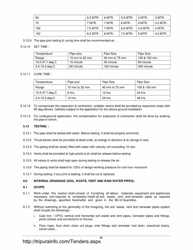
23
63 6.5 MTR. 6 MTR. 5.5 MTR. 4 MTR. 3 MTR.
75 7 MTR. 7 MTR. 6 MTR. 4 MTR. 3.5 MTR.
100 7.5 MTR. 7 MTR. 6.5 MTR. 4.5 MTR. 4 MTR.
150 8.5 MTR. 8 MTR. 7.5 MTR. 5 MTR. 4.5 MTR.
5.12.9 The pipe joint setting & curing time shall be recommended as :
5.12.10 SET TIME :
Temperature Pipe size Pipe Size Pipe Size
Range 15 mm to 32 mm 40 mm to 75 mm 100 & 150 mm
15.5-37.7 deg C 15 minute 30 minute 60 minute
4.4-15.5 deg C 60 minute 120 minute 240 minute
5.12.11 CURE TIME :
Temperature Pipe size Pipe Size Pipe Size
Range 15 mm to 32 mm 40 mm to 75 mm 100 & 150 mm
15.5-37.7 deg C 6 hrs. 12 hrs. 24 hrs.
4.4-15.5 deg C 12 hrs. 24 hrs. 48 hrs.
5.12.12 To compensate the expansion & contraction, suitable means shall be provided by expansion loops with
90 deg elbows / bellows subject to the application for the above ground installation 5.12.13 For underground application, the compensation for expansion & contraction shall be done by anaking
the pipe in trench. 5.13 TESTING : 5.13.1 The pipe shall be tested with water. Before testing, it shall be properly anchored. 5.13.2 Thrust blocks shall be provided at dead ends, at change in direction & at cahnge in size. 5.13.3 The piping shall be slowly filled with water with velocity not exceeding 1ft./sec. 5.13.4 Vents shall be provided at high points & air shall be release before testing. 5.13.5 All valves & vents shall kept open during testing to release the air. 5.13.6 The piping shall be tested for 125% of design working pressure for one hour maximum 5.13.7 During testing, if any joint is leaking, it shall be cut & replaced. 6.0 INTERNAL DRAINAGE (SOIL, WASTE, VENT AND RAIN WATER PIPES):
6.1 SCOPE:
6.1.1 Work under this section shall consist of furnishing all labour, materials, equipment and appliances necessary and required to completely install all soil, waste, vent and rainwater pipes as required by the drawings, specified hereinafter and given in the Bill of Quantities.
6.1.2 Without restricting to the generality of the foregoing, the soil, waste, vent and rainwater pipes system
shall include the followings:-
i. Cast Iron / UPVC vertical and horizontal soil waste and vent pipes, rainwater pipes and fittings, joints clamps and connections to fixtures.
ii. Floor traps, floor drain clean out plugs, inlet fittings and rainwater roof drain, area/local drains, trench drain...
http://tripurainfo.com/Tenders.aspx

24
iii. Waste pipes connections from all fixtures e.g. wash basins, sinks, kitchen equipment.
iv. Testing of all pipes.
v. Connection of main.
6.2 GENERAL REQUIREMENTS 6.2.1 All materials shall be new of the best quality conforming to specifications and subject to the approval of
Client’s Representative. 6.2.2 Pipes and fittings shall be fixed truly vertical, horizontal or in slopes as required in a neat workmanlike
manner. 6.2.3 Pipes shall be fixed in a manner as to provide easy accessibility for repair and maintenance and shall
not cause obstruction in shafts, passages etc. 6.2.4 Pipes shall be securely fixed to walls by suitable clamps at intervals specified. 6.2.5 Access doors for fittings and cleanouts shall be so located that they are easily accessible for repair and
maintenance. 6.2.6 All works shall be executed as directed by Client’s Representative. 6.3 CAST IRON PIPES & FITTINGS 6.3.1 Soil, waste, vent and anti-siphonage pipes shall be cast iron pipes with socket and spigot. All pipes
shall be straight and smooth and inside free from irregular bore, blow holes, cracks and other manufacturing defects. Pipes shall be centrifugally spun iron soil pipes conforming to sand cast I.S. 1729-1967.
6.3.2 STANDARD WEIGHT DIMENSIONS AND PIG LEAD REQUIRED FOR JOINTS SHALL BE AS
FOLLOWS:- For conforming to I.S. 1729-1967 (sand cast iron soil pipes and fittings)
Diameter Thickness Overall Internal Depth Weight diameter of 6'length or 1.83 M of socket lead
50 5 11.41 76 25 75 5 16.52 101 25 100 5 21.67 129 25 150 5 31.91 181 32
6.3.3 TOLERANCE Acceptable tolerance for pipes to I.S. 1729 shall be as follows:-
a) Wall thickness -15%
b) Length ± 20 mm
c) Weight ± 10%
6.3.4 FITTINGS
Fittings shall conform to the corresponding Indian Standard as for pipes. Contractor shall use pipes and fittings of matching specification.
Access door shall be secured air and water tight with 3mm thick insertion rubber washer and white lead. The bolts shall be lubricated with grease or white lead for easy removal.
6.3.5 JOINTING:
All soil, waste and vent pipes including fixture connections between traps and soil pipes shall be jointed with refined pig lead conforming to IS: 27-1977 sufficient sken of jute rope shall be caulked to leave a minimum space for the pig lead as given in 6.3.2 to be poured in. After pouring the lead shall be caulked into the joint with caulking tool and hammer. All surplus lead shall be cut and joint left flush with the rim of the socket neatly.
http://tripurainfo.com/Tenders.aspx
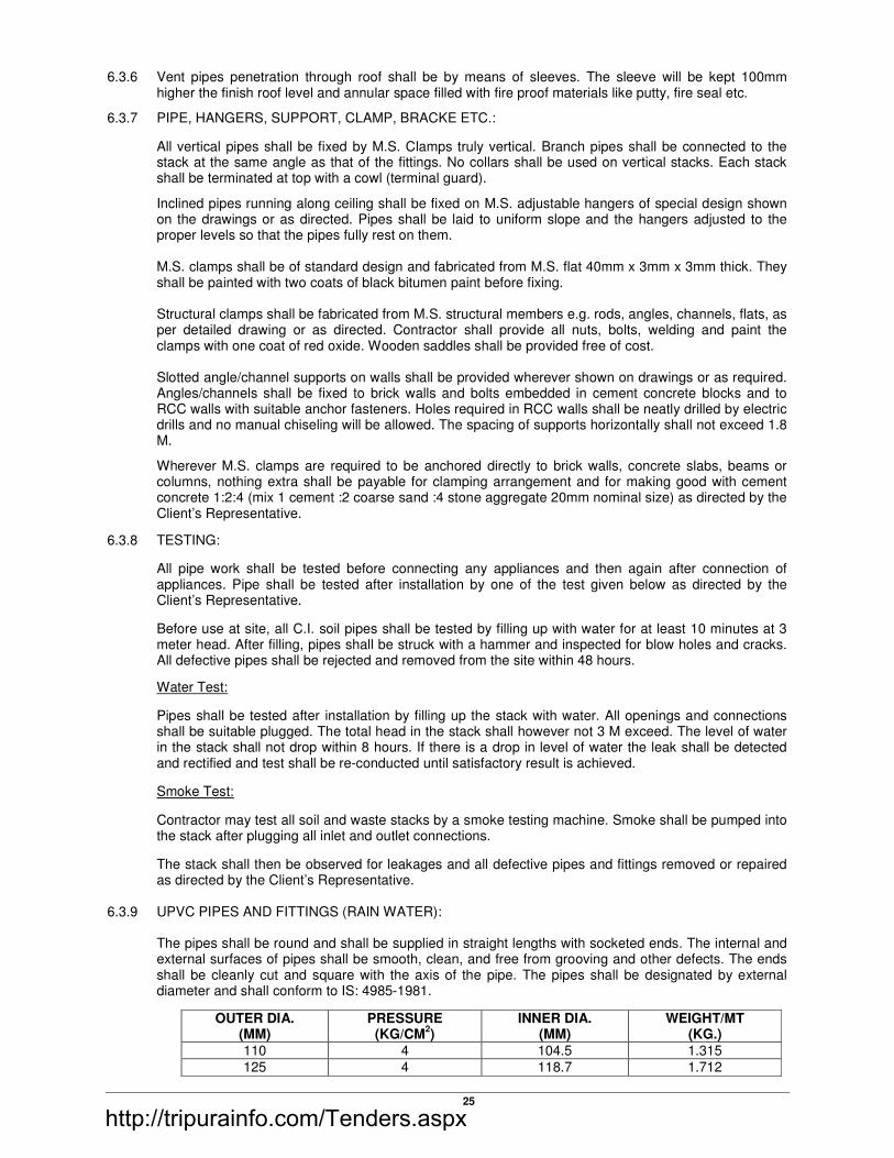
25
6.3.6 Vent pipes penetration through roof shall be by means of sleeves. The sleeve will be kept 100mm higher the finish roof level and annular space filled with fire proof materials like putty, fire seal etc.
6.3.7 PIPE, HANGERS, SUPPORT, CLAMP, BRACKE ETC.:
All vertical pipes shall be fixed by M.S. Clamps truly vertical. Branch pipes shall be connected to the stack at the same angle as that of the fittings. No collars shall be used on vertical stacks. Each stack shall be terminated at top with a cowl (terminal guard).
Inclined pipes running along ceiling shall be fixed on M.S. adjustable hangers of special design shown on the drawings or as directed. Pipes shall be laid to uniform slope and the hangers adjusted to the proper levels so that the pipes fully rest on them.
M.S. clamps shall be of standard design and fabricated from M.S. flat 40mm x 3mm x 3mm thick. They
shall be painted with two coats of black bitumen paint before fixing. Structural clamps shall be fabricated from M.S. structural members e.g. rods, angles, channels, flats, as
per detailed drawing or as directed. Contractor shall provide all nuts, bolts, welding and paint the clamps with one coat of red oxide. Wooden saddles shall be provided free of cost.
Slotted angle/channel supports on walls shall be provided wherever shown on drawings or as required.
Angles/channels shall be fixed to brick walls and bolts embedded in cement concrete blocks and to RCC walls with suitable anchor fasteners. Holes required in RCC walls shall be neatly drilled by electric drills and no manual chiseling will be allowed. The spacing of supports horizontally shall not exceed 1.8 M.
Wherever M.S. clamps are required to be anchored directly to brick walls, concrete slabs, beams or columns, nothing extra shall be payable for clamping arrangement and for making good with cement concrete 1:2:4 (mix 1 cement :2 coarse sand :4 stone aggregate 20mm nominal size) as directed by the Client’s Representative.
6.3.8 TESTING:
All pipe work shall be tested before connecting any appliances and then again after connection of appliances. Pipe shall be tested after installation by one of the test given below as directed by the Client’s Representative.
Before use at site, all C.I. soil pipes shall be tested by filling up with water for at least 10 minutes at 3 meter head. After filling, pipes shall be struck with a hammer and inspected for blow holes and cracks. All defective pipes shall be rejected and removed from the site within 48 hours.
Water Test:
Pipes shall be tested after installation by filling up the stack with water. All openings and connections shall be suitable plugged. The total head in the stack shall however not 3 M exceed. The level of water in the stack shall not drop within 8 hours. If there is a drop in level of water the leak shall be detected and rectified and test shall be re-conducted until satisfactory result is achieved.
Smoke Test:
Contractor may test all soil and waste stacks by a smoke testing machine. Smoke shall be pumped into the stack after plugging all inlet and outlet connections.
The stack shall then be observed for leakages and all defective pipes and fittings removed or repaired as directed by the Client’s Representative.
6.3.9 UPVC PIPES AND FITTINGS (RAIN WATER): The pipes shall be round and shall be supplied in straight lengths with socketed ends. The internal and
external surfaces of pipes shall be smooth, clean, and free from grooving and other defects. The ends shall be cleanly cut and square with the axis of the pipe. The pipes shall be designated by external diameter and shall conform to IS: 4985-1981.
OUTER DIA. (MM)
PRESSURE (KG/CM
2)
INNER DIA. (MM)
WEIGHT/MT (KG.)
110 4 104.5 1.315
125 4 118.7 1.712
http://tripurainfo.com/Tenders.aspx

26
140 4 133.0 2.131
160 4 152.0 2.783
180 4 175.9 3.560
200 2 190.1 4.526
225 4 213.8 5.480
Fittings:
Fittings shall be of the same make as that of pipes, injection moulded and shall conform to Indian Standard.
Laying and Jointing:
The pipes shall be laid and clamped to wooden plugs fixed above the surface of the wall. Alternatively plastic clamps of suitable designs shall be preferred. Provision shall be made for the effect of thermal movement by not gripping or disturbing the pipe at supports between the anchors for suspended pipes. The supports shall allow the repeated movements to take place without abrasion.
Jointing for UPVC pipes shall be made by means of solvent cement for horizontal lines and `O’ rubber ring for vertical line. The type of joint shall be used as per site conditions/direction of the Client’s Representative. Where UPVC pipes are to be used for rain water pipes, the pipe shall be finished with G.I. adopter for insertion in the R.C.C. slab for a water proof joint complete as directed by Client’s Representative.
Supports:
UPVC pipes require supports at close intervals. Recommended support spacing for unplasticised PVC pipes is 1400 mm for pipes 50 mm dia and above. Pipes shall be aligned properly before fixing them on the wooden plugs with clamps. Even if the wooden plugs are fixed using a plumb line, pipe shall also be checked for its alignment before clamping, piping shall be properly supported on, or suspended from clamps, hangers as specified and as required. The Contractor shall adequately design all the brackets, saddles, anchors, clamps and hangers and be responsible for their structural sufficiency. Pipe supports shall be primer coated with rust preventive paint.
Repairs:
While temporary or emergency repairs may be made to the damaged pipes, permanent repairs should be made by replacement of the damaged section. If any split or chip out occurs in the wall of the pipe, a short piece of pipe of sufficient length to cover the damaged portion of the pipe is cut. The sleeve is cut longitudinally and heated sufficiently to soften it so that it may be slipped over the damaged hard pipe.
Testing:
All lengths of PVC rain water pipes shall be fully tested for water tightness by means of water test maintained for not less than 30 minutes. All pipes shall be subjected to a test pressure of at least 1.5 meter head of water head. The test pressure shall, however, not exceed 6 meter head at any point. The pipes shall be plugged preferably with standard design plugs with rubber plugs on both ends. The upper end shall, however, be connected to a pipe for filling with water and getting the required head.
6.3.10 WASTE PIPE FROM APPLIANCES:
i) Waste pipe from appliances e.g. wash basins, sinks, urinals, chrome plate where seen water coolers shall be of galvanised steel (heavy class) conforming to IS:1239-1979.
ii) All pipes shall be fixed in gradient towards the outfalls of drains. Pipes inside a toilet room shall be in chase unless otherwise shown on drawings. Where required pipes may be run at ceiling level in suitable gradient and supported on structural clamps. Spacing for clamps for such pipes shall be as follows:-
Vertical Horizontal
G.I. Pipes 300 cms 240 cms P.V.C. Pipes 180 cms 120 cms
http://tripurainfo.com/Tenders.aspx

27
6.3.11 PAINTING
Soil, waste vent and rainwater pipes in exposed location, in shafts and pipe spaces shall be thoroughly cleaned to remove dirt, rust and other contamination, and painted with two or more coats of synthetic enamel paint to give an even shade.
Paint shall be of approved quality and shade, where directed pipes shall be painted in accordance with approved pipe colour code.
Waste pipes in chase shall be thoroughly cleaned to remove dirt, rust and other contamination, and painted with two coats of bitumen paint, covered with polythene tape and a final coat of bitumen paint. Exposed pipes shall be painted with two or more coats of synthetic enamel paint.
C.I. soil and waste pipes below ground and covered in cement concrete shall not be painted.
6.3.12 MEASUREMENTS: C.I. / UPVC/ G.I. waste/soil, waste, vent and rain water pipes shall be measured over all along the
center line correct to a centimeter including all fittings along its length. The rate for these pipes shall be inclusive of all fittings, holder bat clamps, lead caulked joint for C.I. and cement joints for UPVC and all other items described in the Bill or Quantities. The portion of the pipe within the collar for C.I./UPVC pipe at the joint shall not be included in the length of the pipe work.
6.4. SWR uPVC PIPES AND FITTINGS:
6.4.1 Soil, waste, vent SWR Ring Fit pipes with socket and spigot. All pipes shall be straight and smooth and inside free from irregular bore, blow holes, cracks and other manufacturing defects. These pipes conform to Indian Standard IS: 4985 – 2000 and are designed to withstand continuous internal hydraulic pressure of 4 Kgf/cm so as to ensure life-long trouble free working. The pipes are provided with an integral rubber ring type socket at one end while the other end is kept plain, smooth and free from burrs. Rubber ring type socket ends provide easy push – fit type jointing. Simultaneously, allowance for thermal expansion can also be provided during installation. Pipes shall be centrifugally spun iron soil pipes conforming to sand cast I.S. 1729-1967.
6.4.2 FITTINGS:
Fittings shall conform to the corresponding Indian Standard as for pipes. Contractor shall use pipes and fittings of matching specification.
Access door shall be secured air and water tight with 3mm thick insertion rubber washer and white
lead. The bolts shall be lubricated with grease or white lead for easy removal.
6.4.3 JOINTING:
Rubber Seal Rings for Joints & Access Doors : Manufactured in accordance with IS : 5382 for 75 mm / 90 mm / 110 mm sizes. These are made out of natural rubber with a shore ‘A’ hardness pf 40 × 5. Provide superior resistance to biological attack. Special design of cross section ensures perfect sealing.
Lubricant: Available in 100 gms, 250 gms & 500 gms packing. Specially formulated for compatibility
with rubber seal as well as PVC. Does not support the growth of bacteria or fungi.
6.4.4 PIPE, HANGERS, SUPPORT, CLAMP, BRACKE ETC.:
Supports: UPVC pipes require supports at close intervals. Recommended support spacing for unplastisized PVC
pipes is 1400 mm for pipes 50 mm dia and above. Pipes shall be aligned properly before fixing them on the wooden plugs with clamps. Even if the wooden plugs are fixed using a plumb line, pipe shall also be checked for its alignment before clamping, piping shall be properly supported on, or suspended from clamps, hangers as specified and as required. The Contractor shall adequately design all the brackets, saddles, anchors, clamps and hangers and be responsible for their structural sufficiency. Pipe supports shall be primer coated with rust preventive paint.
6.4.5 TESTING:
Before the system is put into use, it should be tested for leakages by air test, hydraulic test or smoke test.
6.5 TRAPS:
http://tripurainfo.com/Tenders.aspx
28
6.5.1 NAHANI TRAP OR FLOOR TRAPS:
Nahani traps or floor traps shall be cast iron/ PVC / , deep seal with an effective seal of 50 mm. The trap and waste pipes shall be set in cement concrete blocks firmly supported on the structural floor. The blocks shall be in 1:2:3 mix (1 cement: 2 coarse sand: 4 stone aggregate 20 mm nominal size) mixed with water proof compound and extended to 40 mm below finished floor level. Contractor shall provide all necessary shuttering and centering for the blocks. Size of the block shall be 30 x 30 cms of the required depth. The trap shall be installed at lowest point ensure no pending occurs at perimeters of the drain.
6.6 FLOOR TRAP INLET
Bath room traps and connections shall ensure free and silent flow of discharging water. Where specified, the Contractor shall provide a special type galvanised iron inlet fitting without or with one, two or three inlet sockets to receive the waste pipe. Joint between waste and fitting shall be connected to a C.I. ‘P’ or ‘S’ trap with at least 50mm seal (Hopper and traps shall be paid for separately). Floor trap inlet fittings and the trap shall be set in cement concrete blocks.
6.7 C.P./STAINLESS STEEL GRATINGS Floor and Urinal traps shall be provided with 100-150mm square or round C.P./Stainless steel
grating as approved by Client’s Representative with rim, of approved design and shape. Minimum thickness shall be 4-5mm or as specified in the Bill of Quantities.
6.8 CLEANOUT PLUGS Contractor shall provide cast brass cleanout plugs in all horizontal run more than 15 meter length
required one cleanout plugs shall be threaded and provided with key holes for opening. Cleanout plugs shall be fixed to the pipe by a G.I. socket and lead caulked joint.
6.9 PIPE SLEEVES Pipe sleeves 50mm larger diameter than pipes shall be provided wherever pipes pass through walls
and slabs and annular space filled with fire proof materials like putty, fire seal etc. All pipes shall be accurately cut to the required sizes in accordance with relevant BIS codes and burs removed before laying. Open ends of the pipe shall be closed as the pipe is installed to avoid entrance of foreign matters. Vertical sleeve shall finish 50mm above finish floor level.
7.0 EXTERNAL DRAINAGE SYSTEM (SEWERAGE AND STORM WATER): 7.1 SCOPE:
i. Work under this section shall consist of furnishing all labour, materials, equipment and appliances necessary and required to completely install the drainage system as required by the drawings and specified hereinafter or given in the Bill of Quantities.
ii. Without restricting to the generality of the foregoing, the drainage system shall include: Sewer lines including excavations, pipe lines, man holes, drop connections, underground storm
water drains, including pipes, man holes, catch basins and open drains, thrust blocks.
7.2 GENERAL REQUIREMENTS:
All materials shall be new of the best quality conforming to specifications and subject to the approval of the Client’s Representatives.
Drainage lines shall be laid to the required gradients and profiles. All drainage work shall be done in accordance with the local municipal bye-laws. Contractor shall obtain necessary approval and permission for the drainage system from the municipal
or any other competent authority and also existing invert levels required to enter sanitary system. Location of all manholes, catch basins, etc. shall be confirmed by the Client’s Representatives before
the actual execution of work at site.
http://tripurainfo.com/Tenders.aspx
29
All excavation, trenches etc shall be barricaded as per instruction of the Client's Representatives.
All works shall be executed as directed by the Client’s Representatives.
7.3 TRENCHES FOR PIPE & DRAINS:
7.3.1 ALIGNMENT AND GRADE:
The drains are to be laid to alignment and gradients in continuous shown on the drawings but subject to such modifications, as shall be ordered by the Client’s Representative from time to time to meet the requirements of the works. No deviations from the line, depths of cutting or gradients of sewers shown in the plans and sections shall be permitted except by the express direction in writing of the Client’s Representative.
7.3.2 OPENING OUT TRENCHES:
In excavating the trenches at the road metaling, pavement kerbing etc. are to be placed on one side and preserved for rein statement when the trench or other excavation shall be filled-up.
Before any road metal is replaced, it shall be carefully shifted. The surface of all trenches and holes shall be restored and maintained to the satisfaction of the Client’s Representative. The Contractor shall not cut or break down any live fence or trees in the line of the proposed works but shall tunnel under them unless the Client’s Representative shall order to the contrary.
Trench to be excavated to alignment + depth required. Trench to be properly dressed and de-watered. Trench shall be kept free of water at all time. Discharge of water shall be into nearest drainage channel not on the road.
All under ground pipe to be laid open in trench. Pipes to be laid and maintained at required levels and grade during course of work. All joints to be aligned and complete.
Trench shall be of 450mm wide than pipe. Concrete anchors at change in direction for C.I. pipe shall be provided. Pipe shall be rest on cushion in the trench.
The Contractor shall scrub up and clear the surface over the trenches and other excavations of all stumps, roots and all other encumbrances affecting execution of the work and shall remove them from the site to the approval of the Client’s Representative.
7.3.3 CONSTRUCTION ACROSS THE ROADS:
All the pipe line or drain crossing existing road, the road crossing shall be excavated at a time, the second half being commenced after the pipes have been laid in the first half and the trench refilled. Necessary safety measure for traffic as directed shall be adopted. All type of pipes, water mains, cables etc. met within the course of excavation shall be carefully protected and supported. Care shall be taken not to disturb the electrical and communication cable removal of which is necessary shall be arranged by the Client’s Representative or the Contractor shall arrange to support and protect them during excavation.
7.3.4 EXCAVATION TO BE TAKEN TO PROPER DEPTH:
The trenches shall be excavated to such depth and width that the sewers pipe shall rest on cushion so that the inverts may be at the levels given on the section/plan. In bad ground the Client’s Representative may order the Contractor to excavate to a greater depth than that shown on the drawings and to fill up the excavation to the level of the sewer with such materials as decided by Client’s Representative in writing.
7.3.5 REFILLING:
The filling shall be done in layers not exceeding 15mm in depth. Each layer shall be watered, rammed and consolidated. Ramming shall be done with iron rammers where possible and with blunt end of the crow brass where rammers can not be used. Special care shall be taken to ensure that no damage is caused to the pipes, drains, masonry or concrete in the trenches. Filling in trenches shall be commenced soon after the joints of pipes, cables; conduits etc. have been tested and approved by Client’s Representative. The space around the pipes shall be cleared of all debris where the trenches are excavated in hard/soft soil. The filling shall be done with earth on the sides and tops of pipes in layers not exceeding 15mm in depth. Each layer shall be watered rammed and consolidated. The clods and lumps of earth exceeding 8cm in any direction shall be broken or
http://tripurainfo.com/Tenders.aspx
30
removed before the excavated earth is used for filling. Generally no test is done to determine the instrument diversity of filled earth but on the discretion of Client’s Representative the 95 proctor’s compaction test may be done to ensure the in situ density after filling. Consolidation is removal of water from the pores and compaction is the explosion of air from the pores. In case of refilling consolidation places most important role as the watering of the each layer is being done properly. If required by the Client’s Representative proctors needle may also be used for the proper checking of the refilling items of in situ density.
7.3.6 CONTRACTOR SHALL RESTORE SETTLEMENT AND DAMAGES:
The Contractor shall at his own cost make good promptly during the whole period the works are in hand, any settlements that may occur in the surfaces or roads, beams, footpaths, gardens, open spaces etc. Whether public or private caused by his trenches or by his other excavations due to not using the method of compaction as given in clause 7.3.5 and he shall be liable for any accidents caused thereby.
He shall also at his own expense and charges, repair and make good any damage done to the building and other properties.
7.3.7 DISPOSAL OF SURPLUS SOIL:
The Contractor shall at his own cost and charge, dispose off from the site all surpluses excavated material not required to be used on the works.
i. The width of excavated trench shall be as per table given below:
Excavation upto Upto 100 mm Upto 150 mm Dia. Pipe Dia. pipe
90 cms depth 33 cms 33 cms 90 - 150 cms depth 60 cms 60 cms 150 - 300 cms depth 75 cms 75 cms 300 - 500 cms depth 90 cms 100 cms
7.3.8 PROTECTION OF EXISTING SERVICES:
All pipes, water mains, cables etc encountered in the course of excavation shall be carefully protected and supported. In case of any damage caused the same shall be made good at no extra cost failing which necessary works will be carried out by the Clients Representative and contract charged to the Contractor.
7.4 RCC PIPES: 7.4.1 All underground storm water drainage pipes and sewer lines where specified (other than those
specified cast iron) shall be centrifugally spun RCC pipes NP2 for general and NP3 where road crossing. Pipes shall be true and straight with uniform bore throughout. Cracked, wrapped pipes shall not be used on the work. All pipes shall be tested by the manufacturer and the Contractor shall produce, prior to use on site, a certificate to that effect from the manufacturer.
The pipes shall be with or without reinforcement as required and of the class as specified. These shall
conform to IS: 458 - 1971. The reinforced cement concrete pipes shall be manufactured by centrifugal (or spun) process.
All pipes shall be true to shape, straight, perfectly sound and free from cracks and flaws. The external
and internal surface of the pipes shall be smooth and hard. The pipes shall be free from defects resulting from imperfect grading of the aggregate mixing or moulding. The pipes shall be R.C.C. light duty, NP2 and NP3 type.
7.4.2 LAYING: R.C.C. spun pipes shall be laid on cements concrete bed or cradles as specified and shown on the
detailed drawings. The cradles may be pre-cast and sufficiently cured to prevent cracks and breakage in handling. The invert of the cradles shall be left 12mm below the invert level of the pipe and properly placed on the soil to prevent any disturbance. The pipe shall then be placed on the bed concrete or
http://tripurainfo.com/Tenders.aspx

31
cradles and set for the line and gradient by means of sight rails and boning rods, etc. Cradles or concrete bed may be omitted, if directed by the Client’s Representatives.
7.4.3 JOINTING (RIGID SPIGOT AND SOCKET JOINT): Hemp rope soaked in neat cement wash shall be passed round the joint and inserted in it by means of
caulking tool. More skein of yarn shall be added and rammed home. Cement mortar with one part of cement and one part of sand and with minimum water content but on no account soft or sloppy, shall be carefully inserted, punched and caulked into the joint and more cement mortar added until the space of the joint has been filled completely with tightly caulked mortar. The joint shall then be finished off neatly outside the socket at an angle of 45 degree.
7.4.4 CURING: The joint shall be cured for at least seven days. 7.4.5 CEMENT CONCRETE FOR PIPE SUPPORTS:
a) Unless otherwise directed by the Client’s Representative cement concrete for bed, all round or in haunches shall be laid as follows:
Upto 1.5m depth (5’)
Upto 3m depth (10’)
Beyond 3m depth (10’)
Pipes in open ground (no sub soil water) all round (1:5:10)
in haunches (1:3:6)
all round (1:5:10)
RCC/C.I. pipes in sub soil water all round (1:3:6)
in haunches (1:3:6)
in haunches (1:3:6)
RCC/C.I. pipes (in all conditions)
all round (1:3:6)
in haunches (1:3:6)
in haunches (1:3:6)
RCC/C.I pipes under road or building all round (1:3:6)
all round (1:3:6)
all round (1:3:6)
b) RCC pipes or CI pipes may be supported on brick masonry or pre-cast RCC or in situ cradles. Cradles shall be as shown on the drawings.
c) Pipes in loose soil or above ground shall be supported on brick or stone masonry pillars as shown on the drawings.
7.4.6 TESTING: All lengths of the sewer and drain shall be fully tested for water tightness by means of water head
maintained for not less than 30 minutes. Testing shall be carried out from manhole to manhole. All pipes shall be subjected to a test pressure of at least 1.5 meters head of water at the highest point of the section under test. The pipes shall be plugged preferably with standard drain plugs (with rubber rings) on both ends. The upper end shall, however, be connected to a pipe for filling with water and getting the required head.
Permissible drops in water head should not exceed …………………….. 7.4.7 MEASUREMENT:
a) Excavation: Measurement for excavation of pipes trenches shall be made per linear meter. b) Trenches shall be measurement between outside walls of manholes at top and the depth shall be
the average depth between the two ends to the nearest cm. The rate quoted shall be for a depth upto 1.5 meter or as given in the Bill of Quantities.
Payment for trenches more than 1.5 m in depth shall be made for extra depth as given in the Bill of
Quantities and above the rate for depth upto 1.5 m. c) RCC pipes shall be measured for the length of the pipe line per linear meter i.e.:
http://tripurainfo.com/Tenders.aspx

32
i. Length between manholes shall be recorded from inside of one manhole to inside of other
manhole. ii. Length between gully trap and manhole shall be recorded between socket of pipe near gully
trap and inside of manhole. 7.5 STONEWARE PIPE
a) GENERAL REQUIREMENTS 7.5.1 All materials shall be new of the best quality conforming to specifications and subject to the approval of
the Consultant/ Client/ Architect. Drainage lines shall be laid to the required gradients and profiles. 7.5.2 All drainage work shall be done in accordance with the local Municipal by-laws. 7.5.3 Contractor shall obtain necessary approval and permission for the drainage system from the Municipal
or any other competent authority. 7.5.4 Location of all manholes, catch basins etc. shall be got confirmed by the Consultant/ Client/ Architect
before the actual execution of work at site. 7.5.5 All works shall be executed as directed by Consultant/ Client/ Architect.
a) ALIGNMENT AND GRADE
The sewer and storm water drainage pipes shall be laid to alignment and gradient shown on the drawings but subject to such modifications as shall be ordered by the Consultant/ Client/ Architect from time to time to meet the requirements of the works. No deviation from the lines, depth of cutting or gradients of sewers shown on the plans and sections shall be permitted except by the express direction in writing of the Consultant/ Client/ Architect.
b) EXCAVATION
The excavation for sewer works shall be open cutting unless the permission of the Consultant/ Client/ Architect for the ground to be tunneled is obtained in writing. Where sewers have to be constructed along narrow passages, the Consultant/ Client/ Architect may order the excavation to be made party in tunnel and in such cases the excavated soil shall be brought back later on for refilling the trenches or tunnel.
c) OBSTRUCTION OF ROADS
The contractor shall not occupy or obstruct by his operation more than one half of the width of any road or street and sufficient space shall be then left for public and private transit. He shall remove the materials excavated and bring them back again when the trench is required to be refilled. The contractor shall obtain the consent of the Architect in writing before closing any road to vehicular traffic and the foot walks must be clear at all times.
d) EXCAVATION TO BE TAKEN TO PROPER DEPTH
The trenches shall be excavated to such a depth that the sewer shall rest on concrete as described in the several clauses relating there to and so that the inverts may be at the levels given in the sections. In bad ground, the Consultant/ Client/ Architect may order the contractor to excavate to a greater depth than that shown on the drawings and to fill up excavation to the level of the sewers with the concrete, broken stone, gravel or other materials, the contractor, shall be paid extra at rates laid down for such works in the schedule. If the extra work was ordered by the Consultant/ Client/ Architect in writing, but if the contractor shall excavate the trench to a greater depth than is required without a specific order to that effect in writing of the Consultant/ Client/ Architect the extra depth shall have to be filled up with concrete at the contractor’s own cost and charges to the requirements and satisfaction of the Consultant/ Client/ Architect.
e) REFILLING
http://tripurainfo.com/Tenders.aspx

33
After the sewer or other works has been laid and proved to be water tight, the trench or other excavation shall be refilled. Utmost care shall be taken in doing this, so that no damage shall be caused to the sewer and other permanent work. The filling in the haunches and upto 75 cms. Above the crown of the sewer shall consist of the finest selected materials placed carefully in 15 cms. Layers and consolidated. After this has been laid, the trench and other excavation shall be refilled in 15 cms. Layers with materials taken from the excavation, each layer being watered to assist in the consolidation, unless the Architect shall otherwise direct.
f) CONTRACTOR TO RESTORE SETTLEMENT AND DAMAGES
The contractor shall as his own costs and charges, make good promptly during the whole period for the works in hand, any settlement that may occur in the surfaces of roads beams, footpaths, gardens, open spaces etc. whether public or private caused by his trenches or by his other excavations and he shall be liable for any accident caused thereby. He shall also, at his own expense and charges, repair and make good may damage done to building and other property. If in the opinion of the Consultant/ Client/ Architect he fails to make good such works with all practicable dispatch, the Consultant/ Client/ Architect shall be at the liberty to get the work done by other means and the expenses thereof shall be paid by the contractor or deducted from any money that may be or become due to him or recovered from him any other manner according to the law of land.
g) DISPOSAL OF SURPLUS SOIL
The contractor shall at his own costs and charges provide places for disposal of all surplus materials not required to be used on the works. As each trench is refilled the surplus soil shall be immediately removed, the surface properly restored and roadways and sides left clear.
h) TIMBERING OF SEWER AND TRENCHES
1. The contractor shall at all times support efficiently and effectively the sides of the sewer trenches and other excavations by suitable timbering, pilling and sheeting and they shall be closed, timbered in loose or sand strata and below the surface of the sub soil water level.
2. All timbering, sheeting and piling with their walling and supports shall be of adequate dimension
and strength and fully braced and strutted so that no risk of collapse of subsidence of the walls of the trench shall take place.
3. The contractor shall be held responsible and will be accountable for the sufficiency of all timbering, sheeting and pilling used as also for all damage to persons and property resulting from improper quality, strength, maintaining or removing of the same.
i) SHORING OF BUILDINGS
The contractor shall shore up all buildings, walls and other structures, the stability of which is liable to be endangered by the work and shall be fully responsible for all damage to persons or property resulting from any accidents.
j) REMOVAL OF WATER FROM SEWER, TRENCH ETC.
1. The contractor shall at all times during the progress of the work keep the trenches and excavations free from water which shall be disposed of by him in a manner as will neither cause injury to the public health nor to the public or private properly nor the work completed or in progress nor to the surface of any roads or streets, nor cause any interference with the use of the same by the public.
2. If any excavation is carried out at any point or points to a greater width the specified cross section of the sewer with its envelop, the full width of the trench shall be filled with concrete by the contractor at his own expense and charges to the requirements of the Consultant/ Client/ Architect.
k) WIDTH OF TRENCH
The Consultant/ Client/ Architect shall have power by giving an order in writing to the contractor to increase the maximum width in respect of which payment will be allowed for excavation in trenches for various classed of sewer, manholes and other works in certain lengths to be specifically laid
http://tripurainfo.com/Tenders.aspx

34
down by him where on account of bad ground or other unusual conditions, he considers that such increased widths are necessary in view of the site conditions.
Recommended width of trenches at the bottom of the trench are as follows:
100 mm dia pipe 55 cms 150 mm dia pipe 55 cms 225-250 mm dia pipe 60 cms 300 mm dia pipe 75 cms
Maximum width of the bed concrete shall be also as above. No additional payment is admissible for widths greater than specified.
m) SALT GLAZED STONEWARE PIPES:
Stone ware pipe shall be of first class quality salt glazed and free from rough texture inside and outside and straight. All pipes shall have the manufacturers names marked on it and shall comply to IS 651-1971.
n) LAYING AND JOINTING OF STONEWARE SALT GLAZED PIPES :
1. Pipes are liable to be damaged in transit and not with standing tests that may have been made before dispatching each pipe shall be examined carefully on arrival at site. Each pipe shall be rung with a wooden hammer or mallet and those that do not ring true and clear shall be rejected. Sound pipes shall be carefully stacked to prevent damage. All defective pipes should be segregated marked in a conspicuous manner and their use in the works prevented.
2. The pipes shall be laid with sockets leading uphill and should rest on solid and even foundations for the full length of the barrel. Socket holes shall be formed in the foundation sufficiently deep to allow the pipe jointer room to work right round the pipe and as short as practicable to admit the socket and allow the joint to be made.
3. Where pipes are not bedded in concrete the trench bottom shall be left slightly high and carefully bottomed up as pipe laying proceeds so that the pipe barrels rest no firm ground. If excavation has been carried too low it shall be made up with cement concrete at the contractor’s cost and charges.
4. If the bottom of the trench consists of rock or very hard ground that cannot be easily excavated to a smooth surface, the pipes shall be laid on cement concrete bed to ensure even bearing.
o) JOINTING OF PIPES
1. Tarred gasket shall first be wrapped round the spigot of each pipe and the spigot shall then be
placed into the socket of the pipe previously laid, the pipe shall then adjusted and fixed in its correct positions and the gaskin caulked tightly home so as to fill not more than one quarter of the total length of the socket.
2. The remainder of the socket shall be filled with stiff mix of cement mortar (1 cement : 1 clear sharp washed sand). When the socket is filled, a filled should be formed round the joint with a trowel forming an angle of 45 Degrees with the barrel of the pipe. The mortar shall be mixed as needed
For immediate use and no mortar shall be beaten up and used after it has begun to set. 3. After the joint has been made, any extraneous material shall be removed from inside of the joint
with a suitable scraper or ‘badgar’. The newly made joint shall be protected until set from the sun, drying winds, rains or dust. Sacking or other materials which can be kept damp shall be used. The joints shall be exposed and space left all round the pipes for inspection by the Consultant/ Client/ Architect. The inside of the sewer must be left absolutely clear in bore and free from cement mortar or other obstructions throughout its entire length, and shall efficiently drain and discharge.
p) TESTING
1. All lengths of the sewer and drain shall be fully tested for water tightness by means of water pressure maintained for not less than 30 minutes. Testing shall be carried out from manhole to manhole. All pipes shall be subjected to a test pressure of atleast 1.5 mtrs. head of water. The test pressure shall, however, not exceed 6 metres head at any point. The pipes shall be plugged preferably with standard design plugs with rubber plugs on both sides. The upper end
http://tripurainfo.com/Tenders.aspx

35
shall, however, be connected to a pipe for filling with water and getting the required head poured at one time permit.
2. Sewer lines shall be tested for a straightness by :
(i) Inserting a smooth ball 12 mm less than the internal diameter of the pipe. In the absence of obstruction such as yarn or mortar projecting at the joints the ball should roll down the invert of the pipe and emerge at the lower end.
(ii) Means of a mirror at one end and a lamp at the other end. If the pipe line is straight the full circle of light will be seen otherwise obstructions or deviations will be apparent.
(iii) The contractor shall give a smoke test to the drain and sewer at his own expense and charges, if directed by the Consultant/ Client/ Architect.
(iv) A test register shall be maintained which shall be signed and dated by contractor. Architect and representative of consultants.
q) MASONRY WORK
Masonry work for manhole, chambers, septic tanks and such other works as required shall be constructed from local best quality bricks in cement mortar 1 : 5 mix (1 cement : 5 coarse sand) or as specified in the Bill of Quantities. All joints shall be properly raked to receive plaster.
r) CEMENT CONCRETE FOR PIPE SUPPORT
1. Wherever specified or shown on the drawings, all pipes shall be supported in bed all round or in haunches. The thickness and mix of concrete shall be as given in the Bill of Quantities. Widths of the bedding shall be as per Para 13.
2. Unless otherwise directed by the Consultant/ Client/ Architect, cement concrete of bed, all rounds or in haunches shall be laid as follows:
Upto 1.5 m depth
Upto 3 m depth Beyond 3 m depth
RCC, stoneware pipes in open ground (above sub soil water)
All round (1 : 5 : 10)
In haunches (1 : 5 : 10)
In haunches (1 : 5 : 10)
C.I.pipes in sub soil water All round (1 : 3 : 6)
In haunches (1 : 3 : 6)
In haunches (1 : 3 : 6)
RCC or S.W. pipes in sub soil water
All round (1 : 3 : 6)
All round (1 : 3 : 6)
All round (1 : 3 : 6)
RCC or S.W. pipes under floors or building
All round (1 : 2 : 4)
All round (1 : 2 : 4)
All round 3. : 2 : 4)
3. RCC pipes or C.I. or stoneware pipes may be supported on brick masonry or precast RCC or in
situ cradles. Cradles shall be as shown on the drawing. 4. Pipes in loose soil or above ground shall be supported on brick or stone masonry pillars as
shown on the drawings.
5. Hand mixing on properly constructed platforms may be allowed for small quantities by the Consultant/ Client/ Architect. Rate for cement concrete shall be inclusive of all shuttering and centering at all depths and heights.
6. Concrete work shall be of such thickness and mix as given in the Bill of quantities.
7. All concrete work shall be cured for a period of at least 7 days. Such work shall be kept moist by means of gunny bags at all times. All pipes trenches and foundations shall be kept dry during curing period.
7.6 SEWER MANHOLES WITH FRAME AND COVER:
7.6.1 SCOPE
http://tripurainfo.com/Tenders.aspx

36
This specification covers the requirements for providing and constructing of Brick Masonry (for up to 3 mtr. depth) / RCC M 20 grade or 1:1x1/2 :3 mix (for more than 3 mtr. depth) manholes with steps, frame, cover and vent shafts.
7.6.2 STANDARDS
The following standards/codes, unless otherwise specified herein, shall be referred. In all cases, the latest revision of the standards /codes shall be referred to.
IS : 210 Specification for gray iron castings
IS : 269 Specification for ordinary and low heat Portland cement
IS : 383 Specification for coarse and fine aggregates from natural sources for concrete
IS : 432 Specification for mild steel and medium tensile steel bars and hard drawn steel wire for concrete reinforcement
IS : 516 Methods of tests for strength of concrete
IS : 651 Specification for salt-glazed stoneware pipes and fittings
IS : 1077 Specification for common burnt clay building bricks
IS : 1726 Specification for cast iron manhole covers and frames
IS : 1786 Specification for high strength deformed steel bars and wires for concrete reinforcement
IS : 2116 Specification for sand for masonry mortars
IS : 3495 Methods of tests of burnt clay building bricks
IS : 5455 Specification for cast iron steps for manholes
7.6.3 CODES OF PRACTICE
IS : 456 Code of practice for plain and reinforced concrete
IS : 2212 Code of practice for brickwork
IS : 2250 Code of practice for preparation and use of masonry mortars
IS : 4111 Code of practice for ancillary structures in sewerage system part 1manholes
IS : 4127 Code of practice for laying of glazed stoneware pipes
7.6.4 LOCATION Manholes shall be constructed in accordance with the drawings at the locations indicated thereon. 7.6.5 CONSTRUCTION MANHOLES:
At every change of alignment, gradient or diameter of a drain, there shall be a manhole or inspection
chamber. Bends and junctions in the drains shall be grouped together in manhole as far as possible. The maximum distance between manholes shall be according to NBC.
Manholes of different types and sizes as specified shall be constructed in the sewer line at such places and to such levels and dimensions as shown in the drawings or as directed by the Engineer-in- charge. The size specified shall indicate the inside dimensions between brick faces of the manholes. Where the diameter of the drain is increased, the crown of the pipe shall be fixed at the same level and necessary slope given in the invert of the manhole chamber. In exceptional cases and where unavoidable, the crown of the branch sewer may be fixed at lower level but in such cases the peak flow level of the two sewers shall be kept the same. Sewers of unequal sectional area shall not be jointed at the same invert in a manhole. The invert of the smaller sewer at its junction with main shall be at least 2/3 the diameter of the main above the invert of the main. The branch sewers shall deliver sewage in the manhole in the direction of main flow and the junction must be made with care so that flow in main is not impeded.
http://tripurainfo.com/Tenders.aspx

37
No drain from house fittings, e.g. gully trap or soil pipe, etc. to manhole shall normally exceed a length of 6 m unless it is unavoidable. Manholes 90 x 80 cm are generally constructed within compound for house drainage only and near the buildings for house drainage. Manholes 1.2 m x 90 cm are generally constructed for main drainage work for depths less than 1.5 m. Manhole 1.4 m x 90 cm is of the arched type and is generally constructed for main drainage works where depth is 1.50 m or more. The width of manholes shall be increased more than 90 cm on bends or junctions or pipes with diameter greater than 450 mm and that the benching width on either side of the channel is minimum 20 cm. Manholes 1.4 m internal diameter are generally constructed for main drainage works where depth is 2.45 m or more as an alternative to manholes of arch type. The diameter shall be increased suitably, for pipes with diameter greater than 450 mm in the same manner as in the case of rectangular manholes. Before deciding size of manholes, it shall be as specified in BOQ or as per Local Municipal Bye Laws. When manholes are constructed on foot path, these shall be provided with cover of medium duty casting and when built within the width of the road under vehicular traffic, these shall be provided with cover of heavy duty casting.
7.6.6. EXCAVATION
The excavation for manhole shall be true to dimensions and levels shown on the plans or as directed by the Engineer-in-charge.
7.6.7 BED CONCRETE The manhole shall be built on a bed of foundation PCC 1 : 2 : 4 unless required by local authorities.
The thickness of the bed concrete shall be 15 cm for manholes up to 4.5 m depth and 30 cm for depths beyond 4.5 m unless otherwise specified or directed by the Engineer-in-charge. In bad ground, special foundations as suitable shall be provided.
7.6.8. BRICK MASONRY / CEMENT CONCRETE WORK BRICK MASONRY For depth up to 3 mtr, manhole shall be constructed with masonry wall, for more than 3 mtr. Depth, it
shall be of M 20 grade as specified below: The brick work shall be with class 75 bricks in cement mortar 1:4 (1 cement: 4 coarse sand). The brick work shall be with class 75 bricks in cement mortar 1:4 (1 cement: 4 coarse sand). The
external joints of the brick masonry shall be finished smooth, and the joints of the pipes with the masonry shall be made perfectly leak proof. For arched type and circular manholes, brick masonry in arches and arching over the pipes shall be in cement mortar 1 : 3 (1 cement: 3 fine sand). In the case of manholes of circular type the excess shaft shall be corbelled inwardly on three sides at the top to reduce its size to the cover frame to be fitted.
The walls shall be built of one brick thickness for depths up to 4.25 m. below a depth of 4.25 mtr in
ordinary subsoil the wall thickness shall be increased to one and half brick and at 9.75 m below ground two brick thick walls
CEMENT CONCRETE WORK
The walls shall be built of M20 grade (1 cement : 1.5 coarse sand : 3 coarse aggregate having 20 mm nominal size) with 15 cm thickness for depth up to 4.5 m. Below a depth of 4.5 m in ordinary subsoil the wall thickness shall be increased to 30 cm
The thickness of the wall shall be take the total load coming over it including earth pressure & water pressure. The chamber shall be tested for water tightness.
The wall shall further be water proofed with addition of approved water proofing compound in a quantity as per manufacturer's specifications. In case Local Authorities/Bye Laws specify richer specifications, the same shall be adopted.
http://tripurainfo.com/Tenders.aspx

38
For earth work excavation, bed concrete work, R.C.C. work and refilling of earth, respective specifications shall be followed.
PLASTER AND POINTING
In case of brick walls, the walls of the manholes shall be plastered inside with 20 mm thick cement plaster 1:2 (1 cement: 2 coarse sand) finished smooth. The plaster shall further be water proofed with addition of approved water proofing compound in a quantity as per manufacturer's specifications. In case Local Authorities/Bye Laws specify richer specifications, the same shall be adopted.
For earth work excavation, bed concrete brick work, plaster and pointing, R.C.C. work and refilling of earth, respective specifications shall be followed.
7.6.9 BENCHING
The channels and benching shall e done in cement concrete 1:1.5:3 (1 cement : 1.5 coarse sand : 3 graded stone aggregate 20 mm nominal size) and rendered smooth with neat cement. The depth of channels and benching shall be as given in Table .
TOP OF CHANNEL AT DEPTH OF BENCHING SIZE OF DRAIN THE CENTER ABOVE AT SIDE WALLS ABOVE BED CONC. BED CONC.
10 cm 15 cm 20 cm 15 cm 20 cm 30 cm 20 cm 25 cm 35 cm 25 cm 30 cm 40 cm 30 cm 35 cm 45 cm
7.6.10 FOOT RESTS
All manholes deeper than 0.8 m shall be provided with foot rests.
7.6.10.1 Foot rest shall be CI type, each weighing 5.5 Kg, 1:2:4 coping. 7.6.10.2 Alternatively MS foot rest shall be provided. These shall be embedded 20 cm deep in 20 x 20 x 10 cm
blocks of cement concrete 1:2:4 (1 cement : 4 coarse sand : 4 graded stone aggregate 20 mm nominal size). The concrete block with M.S. foot rest placed in its center shall be cast in situ along with the RCC wall & finished smooth.
SIZE OF DRAIN MM
TOP OF CHANNEL AT THE CENTER ABOVE BED
CONCRETE CM
DEPTH OF BENCHING AT SIDE WALLS ABOVE BED
CONCRETE CM
100 15 20
150 20 30
200 25 35
250 30 40
300 35 45
350 40 50
400 45 55
450 50 60
Foot rests which shall be of 20x20 Sq. M.S. bars. Foot rests shall be fixed 40 cm apart vertically and staggered laterally and shall project 10 cm beyond
the surface of the wall. The top foot rest shall be 45 cm below the manhole cover. Foot rests shall be painted with coal tar, the portion embedded in the cement concrete block being
painted with thick cement slurry before fixing.
7.6.11 MANHOLE COVERS AND FRAMES
http://tripurainfo.com/Tenders.aspx

39
The frame of manhole shall be firmly embedded to correct alignment and levels in R.C.C. slab or plain concrete as the case may be on the top of the masonry. After completion of the work, manhole covers shall be sealed by means of thick grease.
7.6.12 MEASUREMENTS
Manholes shall be enumerated under relevant items. The depth of the manhole shall be reckoned from the top level of RCC cover to the invert level of channel. The depth shall be measured correct to a cm. The extra depth shall be measured and paid as extra over the specified depth.
7.6.13 RATE The rate shall include the cost of materials and labour involved in all the operations described above
but exclude the cost of (i) excavation, (ii) refilling (iii) dewatering if required. These items shall be paid for separately under relevant items of work.
Payment for extra depths of manholes shall be made separately under relevant items of work. 7.7 DROP CONNECTION
In cases where branch pipe sewer enters the manhole of main pipe sewer at a higher level than the main sewer, a drop connection shall be provided. The work shall be carried out as per specifications and RCC pipes and special conforming to IS: 458 shall be of the same size as that of the branch pipe sewer.
For 150 and 250 mm main line, if the difference in level between the water line (peak flow level) and the
invert level of the branch line is less than 60 cm, a drop connection may be provided within the manhole by giving suitable ramp. If the difference in level is more than 60 cm, the drop shall be provided externally.
The sewer main lines shall be designed with 0.8 full flow. 7.7.1 EXCAVATION The excavation shall be done for the drop connection at the place where the branch line meets the
manhole the excavation shall be carried up to the bed concrete of the manhole and to the full width of the branch line.
7.7.2 MEASUREMENTS Drop connection shall be enumerated. The depths beyond 60 cm shall be measured in running metres
correct to a cm under relevant items. 7.7.3 RATE The rate shall include the cost of labour and materials involved in all the operations described above
but excluding the cost of excavations and refilling.
7.7.4 TESTING The interior of manholes shall be cleared of all debris after construction and before testing the same for
water tightness by Contractor.
Water for testing of manholes along with pipeline shall be arranged by Contractor at his own cost. 7.7.5 R.C.C PRE CAST M.H.F.C. Manufacture, supply delivery at site of work and fixing on top of manhole precast RCC Frame & cover
suitable to drainage M.H. and including cost of reinforcement M.S. Angles or Flat, curing, mold work etc.
7.7.6 GENERAL SPECIFICATION R.C.C Precast manhole frame & cover shall be manufacture as per standard type design. Frame shall
confirm to IS: 12592 part – II – 1991. Cover shall confirm to IS : 12592 part – I – 1988.
http://tripurainfo.com/Tenders.aspx

40
7.7.7 MATERIAL
Sand, cement, water, aggregates and reinforcement steel shall confirm to relevant I.S. specifications. Thickness of frame shall be 10 cm. Necessary reinforcement, M.S. angle or flat shall be placed as per design during the concreting work fabrication of R.C.C. M.H.F.C shall be carried out by mechanically vibrating process.
7.7.8 INSPECTION :
Inspection of materials will be carried out at work site by the Engineer who shall carry out inspection as soon as material is brought on work site. Inspection will be carried out normally within one week time. The supplier has to take care of the following points.
The manufacturer has to go in for one line stenciling for identifying size and class for proper separation. The unloaded material has to be stacked in manageable batches with adequate inspection space like
spreading the pieces etc. to permit proper inspection. 7.7.9 TRANSIT RISK The contractor shall bring goods at his own risk or it should be covered against the transit risk at its own
cost.
7.7.10 TEST CERTIFICATE The contractor shall always provide manufacturer’s test certificate in accordance with every batch/lot of
goods so manufactured and supplied. The supplier shall also produce in addition to manufacturer’s test certificate as mentioned in above, the
inspection certificate issued by Engineer for the same purpose. 7.7.11 FIXING Precast R.C.C. frame shall be fixed on the top of manhole and properly embedded in cement concrete
1:1.5:3 in required quantity in such a way that the top of the cover when placed in position shall remain at the finished road level.
7.7.12 MEASUREMENT The measurement shall be made on number basis subsequent to fixing the frame on top of manhole
and placing the cover in the frame. 7.7.13 MARKING Each manhole frame and cover shall have cast on them the following information. a) Manufacturer's name or trademark. b) Grade denoted by abbreviation such as HD, MD or LD. c) The word SWD or sewer to denote storm water drain or sewer respecting if desired. d) An identification name as required by purchaser. 8.0 EQUIPMENT SPECIFICATIONS: 8.1 HYDROPNEUMATIC SYSTEM 8.1.1 SCOPE: The specification covers design, performance, manufacture, construction features, inspection, testing,
delivery, installation, commissioning of Hydro pneumatic pressurized system consisting of balancing tank with mounting pads, pump-motor set with coupling and coupling guard, common base plate, bell mouth, piping, isolation valves, NRVs, fittings, control panel, pressure switches, etc. and other accessories required for complete installation of hydro pneumatic system at site.
8.1.2 CONSTRUCTION FEATURES:
http://tripurainfo.com/Tenders.aspx

41
The major components of the system shall be as follows : 8.1.2.1 TANK: The tank shall be of M.S. fabricated. The shell and dished ends shall be fabricated from 8 mm and 10
mm thick M.S. plate respectively. The tank shall be supplied with air compressor with all accessories to supply compressed air to the
tank. The compressor shall be oil free, Teflon coated. Due to this, air shall be compressed when the water enters and shall supply the water at constant pressure.
Alternatively FRP tank (Pressure vessel) for min. 8 Kg/cm
2 Pressure rating with inbuilt aircell to be
provided if specified in BOQ. The tank shall be provided with all accessories viz. mounting arrangement, isolation valve, pressure
gauge, etc. 8.1.2.2 PUMP: Two types of pumps i.e. inline vertical centrifugal pump or centrifugal end suction / monoblock pumps
shall be provided. Variable frequency drive shall be provided with one of the installed pump – if specified in Schedule of quantity.
The pump – motor set and shall be suitable for 3 Ph., 415 V, 50 Hz., AC power supply and having 2900
RPM speed. The pump shall be installed with isolation butterfly valve, non return valve, etc. The detailed specification for pump & motor is as below :
Vertical inline / End suction / monoblock Centrifugal Pump 8.1.2.3 Codes & Standards : The design and manufacture of the pump shall comply with all currently applicable statutes, regulations
and safety codes in the locality where the equipment will be installed. 8.1.2.4 Design Features: The pump shall be capable of developing required total head at rated capacity. Impeller shall be closed
type and shall be dynamically balanced. The pump shall have non overloading characteristics. 8.1.2.5 Constructional Features : The casing shall be of rigid construction and shall have side suction and side delivery in case of inline
pump and side suction and central delivery in case of submersible centrifugal pump. The pump shall have very small length suction and delivery pipe connections which will result in
minimum friction loss. Impeller shall be of one piece and shall be of SS CF8 M . The shaft shall be of S.S. and its surface shall be properly finished. Shaft sleeves shall be provided to protect shaft from any damage. Bearing shall be ball or roller type. Mechanical seal shall be provided to avoid any leakage. 8.1.2.5 Inspection & Testing : The pump shall be offered for visual inspection before dispatch. Material test certificates for the various pump components shall be furnished for purchaser’s approval.
http://tripurainfo.com/Tenders.aspx

42
Hydrostatic test shall be carried out at 1.5 times the maximum discharge pressure. All the tests shall be witnessed by purchaser. 8.1.2.6 Drawings: Following drawings shall be furnished by the vendor:
1) Overall dimensional drawing. Cross-sectional drawings with Bill of Material and Material of Construction 8.1.2.7 Accessories: The pump shall be provided with all accessories such as base plate, foundation bolts, strainer, pressure
gauge, etc. All accessories required for proper and safe operation shall be furnished with the pumps. 8.1.2.8 PRESSURE SWITCH: The system shall be installed with the pressure switch which shall be set at predetermined pressure to
automatically control the pump operation. 8.2 VALVES 8.2.1 Scope: This specification covers the design requirements, features of construction, inspection, testing, painting,
delivery, installation and commissioning of manually hand wheel operated butterfly valves, spring operated dual / single plate non return valve & non rising sluice valve with hardwares & gaskets, etc. at site.
8.2.2 Codes & Standards: The design and manufacture of the valves shall comply with all currently applicable statutes,
regulations and safety codes in the locality where the equipment will be installed. Nothing in this specification shall relieve the vendor of this responsibility. Ball valve according to relevant BS/Butterfly Valves shall be confirming to BS 5155, PN 1.0, Non Return Valves shall conform to API 594 / 598 & Sluice valve shall conform to IS 14846 PD.
8.2.3 Design Requirements for Ball Valves : Ball valve shall be provided on suction and delivery side of each pump. Valves shall be provided with SS ball & stem. The valve shall be flanged type. All internal wetted parts shall be of S.S. Seating shall be of PTFE. OR 8.2.3 Design Requirements for Butterfly Valves : Butterfly valve shall be provided on suction and delivery side of each pump. Valves shall be provided with integrally moulded liner to provide perfect seating arrangement. The valve shall be flanged type. All internal wetted parts shall be of S.S. Disc seal shall be of EPDM. 8.2.4 Design Requirements for Non Return Valves : Non Return Valve shall be provided on delivery side of each pump. The non return valves shall be provided with soft seating.
http://tripurainfo.com/Tenders.aspx
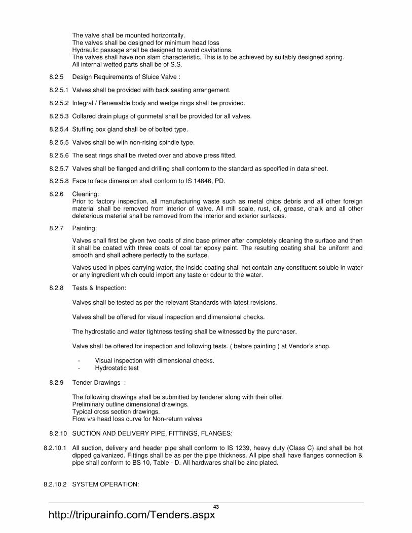
43
The valve shall be mounted horizontally. The valves shall be designed for minimum head loss Hydraulic passage shall be designed to avoid cavitations. The valves shall have non slam characteristic. This is to be achieved by suitably designed spring. All internal wetted parts shall be of S.S.
8.2.5 Design Requirements of Sluice Valve :
8.2.5.1 Valves shall be provided with back seating arrangement.
8.2.5.2 Integral / Renewable body and wedge rings shall be provided.
8.2.5.3 Collared drain plugs of gunmetal shall be provided for all valves.
8.2.5.4 Stuffing box gland shall be of bolted type.
8.2.5.5 Valves shall be with non-rising spindle type.
8.2.5.6 The seat rings shall be riveted over and above press fitted.
8.2.5.7 Valves shall be flanged and drilling shall conform to the standard as specified in data sheet.
8.2.5.8 Face to face dimension shall conform to IS 14846, PD.
8.2.6 Cleaning: Prior to factory inspection, all manufacturing waste such as metal chips debris and all other foreign
material shall be removed from interior of valve. All mill scale, rust, oil, grease, chalk and all other deleterious material shall be removed from the interior and exterior surfaces.
8.2.7 Painting:
Valves shall first be given two coats of zinc base primer after completely cleaning the surface and then it shall be coated with three coats of coal tar epoxy paint. The resulting coating shall be uniform and smooth and shall adhere perfectly to the surface.
Valves used in pipes carrying water, the inside coating shall not contain any constituent soluble in water or any ingredient which could import any taste or odour to the water.
8.2.8 Tests & Inspection:
Valves shall be tested as per the relevant Standards with latest revisions. Valves shall be offered for visual inspection and dimensional checks. The hydrostatic and water tightness testing shall be witnessed by the purchaser. Valve shall be offered for inspection and following tests. ( before painting ) at Vendor’s shop.
- Visual inspection with dimensional checks. - Hydrostatic test
8.2.9 Tender Drawings : The following drawings shall be submitted by tenderer along with their offer.
Preliminary outline dimensional drawings. Typical cross section drawings. Flow v/s head loss curve for Non-return valves
8.2.10 SUCTION AND DELIVERY PIPE, FITTINGS, FLANGES:
8.2.10.1 All suction, delivery and header pipe shall conform to IS 1239, heavy duty (Class C) and shall be hot dipped galvanized. Fittings shall be as per the pipe thickness. All pipe shall have flanges connection & pipe shall conform to BS 10, Table - D. All hardwares shall be zinc plated.
8.2.10.2 SYSTEM OPERATION:
http://tripurainfo.com/Tenders.aspx
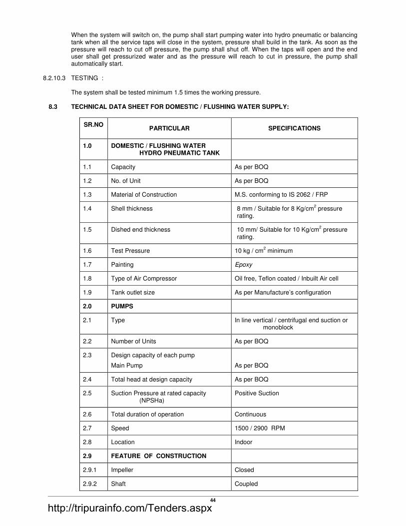
44
When the system will switch on, the pump shall start pumping water into hydro pneumatic or balancing tank when all the service taps will close in the system, pressure shall build in the tank. As soon as the pressure will reach to cut off pressure, the pump shall shut off. When the taps will open and the end user shall get pressurized water and as the pressure will reach to cut in pressure, the pump shall automatically start.
8.2.10.3 TESTING :
The system shall be tested minimum 1.5 times the working pressure. 8.3 TECHNICAL DATA SHEET FOR DOMESTIC / FLUSHING WATER SUPPLY:
SR.NOPARTICULAR SPECIFICATIONS
1.0 DOMESTIC / FLUSHING WATER HYDRO PNEUMATIC TANK
1.1 Capacity As per BOQ
1.2 No. of Unit As per BOQ
1.3 Material of Construction M.S. conforming to IS 2062 / FRP
1.4 Shell thickness 8 mm / Suitable for 8 Kg/cm2 pressure
rating.
1.5 Dished end thickness 10 mm/ Suitable for 10 Kg/cm2 pressure
rating.
1.6 Test Pressure 10 kg / cm2 minimum
1.7 Painting Epoxy
1.8 Type of Air Compressor Oil free, Teflon coated / Inbuilt Air cell
1.9 Tank outlet size As per Manufacture’s configuration
2.0 PUMPS
2.1 Type In line vertical / centrifugal end suction or monoblock
2.2 Number of Units As per BOQ
2.3 Design capacity of each pump
Main Pump
As per BOQ
2.4 Total head at design capacity As per BOQ
2.5 Suction Pressure at rated capacity (NPSHa)
Positive Suction
2.6 Total duration of operation Continuous
2.7 Speed 1500 / 2900 RPM
2.8 Location Indoor
2.9 FEATURE OF CONSTRUCTION
2.9.1 Impeller Closed
2.9.2 Shaft Coupled
http://tripurainfo.com/Tenders.aspx

45
SR.NOPARTICULAR SPECIFICATIONS
2.9.3 Drive Transmission Direct
2.9.4 Seal Gland Packing
2.9.5 Mounting Common base plate
2.9.6 No. of stage Single
2.9.8 Starter
Pump
DOL / VFD
2.9.9 Flange drilling As per BS 10, Table D, flat face with off centre bolt holes
2.10 LIQUID DATA
2.10.1 Liquid handled Water
2.10.2 Specific gravity 1.0
2.10.3 Temperature Ambient temp.
2.11 MATERIAL OF CONSTRUCTION (AS INDICATED IN BOQ OR AS SPECIFIED BLEOW IF NOT GIVEN IN BOQ)
2.11.1 Base plate M.S. IS 226
2.11.2 Pump Casing C.I.
2.11.3 Impeller SS CF 8 M
2.11.4 Shaft S.S AISI 410
2.11.5 Wearing Ring SS 316
2.11.6 Painting Epoxy
2.11.7 Hardware in contact with water Hot dipped galvanized
2.11.8 Companion flanges M.S., BS 10, Table D
2.12 ACCESSORIES & SERVICES REQUIRED
2.12.1 Base Plate YES
2.12.2 Foundation bolts YES
2.12.3 Companion flanges YES
2.12.4 Spare parts required YES
2.12.5 Maintenance tools required YES
3.0 Cut in pressure Working Pump
( As per IS)
Stand by Pump
( As per IS)
4.0 Cut off pressure
Working Pump
( As per IS)
Stand by Pump
( As per IS)
http://tripurainfo.com/Tenders.aspx

46
SR.NOPARTICULAR SPECIFICATIONS
5.0 INDUCTION MOTOR
5.1 Type Squirrel cage Induction
5.2 Mfg. Standard IS 325
5.3 Rated Voltage 415 Volts, 3 Phase, 50 Hz., AC
5.4 Voltage and frequency variation ± 10% voltage variation
± 5% frequency variation
± 10% combined voltage and frequency variation
5.5 Speed in RPM 1500/2900 RPM
5.6 Class of Insulation Class B
5.7 Degree of Protection IP 55
6.0 Suction & delivery piping MS, hot dipped galvanized, Class `C’
7.0 Suction, delivery valves & header valves Required, flanged Cast Iron valves with SS internal parts
Make : Kirloskar / KSB / ZOLOTO/AUDCO/ FLOVEL
Flanged Ball / Butterfly valve on suction and delivery of each pump & Flanged Non slam, spring operated dual plate type check valve on delivery side of each pump & on header
8.0 Control Panel With Starter.
One pump of similar rating shall have VFD
Required with all protections & sequential timer for main pumps
Also required Finolex / CCI / Gloster make cable from motor to panel
9.0 Level Indicator Required for 0-5 mtr. Range and shall be panel mounted and interlocking with pump
10.0 Pressure switch Provided for each pump
11.0 Pressure Gauge Required at delivery of each pump & on header. Range 0-7 kg/cm2
12.0 Gaskets ‘Champion ‘ make
13.0 Hardware Zinc coated
8.4 CENTRIFUGAL PUMPS
8.4.1 SCOPE:
This specification covers the supply, installation, testing & commissioning of Centrifugal type (monoblock/moonset/End suction) pumps. The scope also includes delivery piping upto Discharge
http://tripurainfo.com/Tenders.aspx

47
Header with necessary pipe, fittings, etc. Each pump shall have isolation gun metal gate valve & NRV at delivery side. The pipe shall be GI class B.
8.4.2 CODES AND STANDARDS:
The design and manufacture of the pump shall comply with all currently applicable statutes, regulations and safety codes in the locality where the equipment will be installed.
8.4.3 DESIGN FEATURES: 8.4.3.1 The pump shall be capable of developing required total head at rated capacity.
8.4.3.2 Impeller shall be enclosed type and shall be dynamically balanced. 8.4.3.3 The pump shall have non overloading characteristics. 8.4.3.4 The pump shall have positive suction. 8.4.4 CONSTRUCTIONAL FEATURES: 8.4.4.1 The casing shall be of rigid construction and shall have central delivery pipe. 8.4.4.2 The casing shall be of Cast Iron. 8.4.4.3 The pump shall have very small length suction and delivery pipe connections which will result in
minimum friction loss in case of moonset pumps. 8.4.4.4 Impeller shall be of one piece and shall be of SS CF 8 M. 8.4.4.5 The shaft shall be of S.S. and its surface shall be properly finished. 8.4.4.6 Shaft sleeves shall be provided to protect shaft from any damage. 8.4.4.7 Bearing shall be ball or roller type. 8.4.4.8 Mechanical seal shall be provided to avoid any leakage. 8.4.5 INSPECTION AND TESTING: 8.4.5.1 The pump shall be offered for visual inspection before dispatch. 8.4.5.2 Material test certificates for the various pump components shall be furnished for purchaser’s approval. 8.4.5.3 Hydrostatic test shall be carried out at 1.5 times the maximum discharge pressure. 8.4.5.4 All the tests shall be witnessed by purchaser. 8.4.6 DRAWINGS: Following drawings shall be furnished by the vendor:
1) Overall dimensional drawing.
2) Cross-sectional drawings with Bill of Material and Material of Construction
TECHNICAL SPECIFICATIONS FOR CENTRIFUGAL PUMPS
SR. NO. PARTICULAR SPECIFICATIONS
1.0 Type Centrifugal Monoblock / Monoset / End suction
2.0 Number of Units As per BOQ
http://tripurainfo.com/Tenders.aspx

48
SR. NO. PARTICULAR SPECIFICATIONS
3.0 Design capacity of each pump As per BOQ
4.0 Total head at design capacity As per BOQ
5.0 Total duration of operation As per BOQ
6.0 Speed 2900 RPM
7.0 Location As per BOQ & Layout
8.0 FEATURE OF CONSTRUCTION
8.1 Impeller Enclosed
8.2 Shaft Coupled
8.3 Drive Transmission Direct
8.4 Seal Mechanical
8.5 Mounting Base plate
8.6 No. of stage Single
8.7 Nozzle orientation
A. Suction
B. Discharge
Side suction
Top discharge
8.8 Starter DOL for upto 5 KW & Star / Delta for more than 5 KW rating
8.9 Flange drilling As per BS 10, Table F, raised face with off center bolt holes
9.0 LIQUID DATA
9.1 Liquid handled HVAC make up soft Water
9.2 Specific gravity 1.0
9.3 Temperature Ambient temp.
10.0 MATERIAL OF CONSTRUCTION
10.1 Base plate M.S. IS 226
10.2 Pump Casing Cast Iron
10.3 Impeller SS CF8 M
10.4 Shaft S.S AISI 410
10.5 Wearing Ring S.S AISI 410
10.6 Painting Epoxy
10.7 Hardware in contact with water Hot dipped galvanized
10.8 Companion flanges M.S., BS 10, Table F
10.9 Make KSB / KIRLOSKER/GROUNDFOS
11.0 ACCESSORIES & SERVICES REQUIRED
11.1 Base Plate YES
11.2 Foundation bolts YES
11.3 Companion flanges YES
11.4 Spare parts required YES
11.5 Maintenance tools required YES
12.0 MOTOR :
12.1 Power Supply 230 / 415 Volts, 3 phase, 50 Hz. AC
12.2 Class of Insulation Class B
12.3 Degree of Protection IP 55
http://tripurainfo.com/Tenders.aspx

49
SR. NO. PARTICULAR SPECIFICATIONS
13.0 Delivery piping GI, Class `B’
14.0 Delivery valves & header valves Gun Metal flanged valves
Make : AUDCO / ZOLOTO / KSB / IVC
For monoset pump :
Flanged Ball / Butterfly valve on delivery side of each pump & Flanged Non Return Valve on delivery side of each pump & on header
For monoblock / end suction pump :
Flanged Ball / Butterfly valve on suction & delivery side of each pump & Flanged Non Return Valve on delivery side of each pump & on header
15.0 Starter Panel Required with pump interlocking with respect to tank levels.
Also required Finolex / Polycab make cables up to starter panel.
16.0 Level Indicator Required for 0-5mtr. Range and shall be panel mounted and interlocking with pump and over head tank.
17.0 Pressure Gauge Required at delivery of each pump & on header.
0 –7 kg/sq.cm
8.5 GUN METAL GATE VALVE
8.5.1 SCOPE: This specification covers supply, installation, testing & commissioning of Gun Metal gate valve with
gaskets, hardware, etc. at site.
8.5.2 CODES AND STANDARDS:
8.5.2.1 The design and manufacture of the valves shall comply with all currently applicable statutes, regulations and safety codes in the locality where the equipment will be installed. Nothing in this specification shall relieve the vendor of this responsibility. Valves shall be confirming to IS 778 PN 1.0 (Class 1).
8.5.3 DESIGN REQUIREMENTS FOR GATE VALVES: 8.5.3.1 Valves shall be provided with back seating arrangement. 8.5.3.2 Body seat shall be Integral type. 8.5.3.3 Collared drain plugs of gunmetal shall be provided for all valves. 8.5.3.4 Stuffing box gland shall be of integral bolted type. 8.5.3.5 Valves shall be with non-rising spindle type. 8.5.3.6 Valves shall be flanged and drilling shall conform to the standard as specified in data sheet. 8.5.3.7 Face to face dimension shall be as per IS 778 PN 1.0. 8.5.3.8 All face and seat rings shall be force fitted and additionally shall be riveted to the recesses in the C.I.
casting.
http://tripurainfo.com/Tenders.aspx

50
8.5.4 CLEANING: Prior to factory inspection, all manufacturing waste such as metal chips, debris and all other foreign
material shall be removed from the interior of the valve. All mill scale, rust, oil, grease, chalk and all other material shall be removed from the interior and exterior surfaces.
8.5.5 PAINTING: 8.5.5.1 Valves shall first be given two coats of zinc base primer after completely cleaning the surface and then
it shall be coated with three coats of coal tar epoxy paint. The resulting coating shall be uniform and smooth and adhere perfectly to the surface.
8.5.5.2 Valve used in pipes carrying water, the inside coating shall not contain any constitute soluble in water
or any ingredient which could import any taste or odour to the water 8.5.6 DIRECTION OF FLOW: Direction of flow shall coincide with the flow direction indicated by “arrow” cast on the valve body. 8.5.7 TESTS AND INSPECTION: 8.5.7.1 Valves shall be offered for visual inspection and dimensional check. 8.5.7.2 Valves shall be tested as per IS 778 PN 1.0 with latest amendments. 8.5.7.3 The hydrostatic testing shall be witnessed by the purchaser. 8.5.7.4 Valve shall be dispatched only after visual inspection and clearing instruction for dispatch. 8.5.8 TENDER DRAWINGS: The following drawings shall be submitted by Bidder along with the quotation. 8.5.8.1 Preliminary outline dimensional drawings.
8.5.8.2 Typical cross section drawings.
http://tripurainfo.com/Tenders.aspx

51
DOCUMENT: TECHNICAL DATA SHEET FOR GUN METAL GATE VALVE
SR. NO. PARTICULARS PUMP HOUSE
1.0 Type of Valves Flanged, Non rising spindle type
2.0 Size range and quantity As per BOQ
3.0 Fluid Water
4.0 Pressure Rating Class 1
5.0 Stem Non Rising
6.0 Ends Flat faced Flanged as per IS 778 Class 1
7.0 Bonnet Screwed on
8.0 Disc. Solid wedge
9.0 Operation Hand wheel Operation
10.0 Seat Integral
11.0 Other requirements Valves shall close in clockwise rotation of the hand wheel.
12.0 Body / bonnet Leaded Tin Bronze conforming to IS 318, LTB2
13.0 Disc Leaded Tin Bronze conforming to IS 318, LTB2
14.0 Stem High Tensile Brass
15.0 Body seat Bronze IS 318 Gr LTB2
16.0 Disc seat Bronze IS 318 Gr LTB2
17.0 Stem nut Bronze IS 318 GR LTB2
18.0 Back Seat Bush Bronze IS 318 GR LTB2
19.0 Stuffing box Bronze IS 318 Gr LTB2
20.0 Gland Bronze IS 318 Gr LTB2
21.0 Packing Graphited Asbestos
22.0 Bolts, studs & nuts Carbon Steel IS :1367 Class 4.6 / 4
23.0 Testing :
Shell test
15 Kg / Cm²
Seat test 10 Kg / Cm²
8.6 GUN METAL NON RETURN VALVE
http://tripurainfo.com/Tenders.aspx

52
8.6.1 SCOPE:
This specification covers the supply, installation, testing & commissioning of Gun Metal Non Return Valve with gasket hardware, etc. at site.
8.6.2 CODES AND STANDARDS:
8.6.2.1 The design and manufacture of the valves shall comply with all currently applicable statutes, regulations and safety codes in the locality where the equipment will be installed. Nothing in this specification shall relieve the vendor of this responsibility. The valve shall be conforming to IS 778 PN 1.0 (Class 1).
8.6.3 DESIGN REQUIREMENTS FOR NON RETURN VALVES:
8.6.3.1 The non return valves shall be provided with metal seating.
8.6.3.2 The valve shall be mounted horizontally.
8.6.3.3 The valves shall be designed for minimum head loss.
8.6.3.4 Hydraulic passage shall be designed to avoid cavitations.
8.6.3.5 The valves shall have non slam characteristic.
8.6.4 CLEANING:
8.6.4.1 Prior to factory inspection, all manufacturing waste such as metal chips debris and all other foreign material shall be removed from interior of valve. All mill scale, rust, oil, grease, chalk and all other deleterious material shall be removed from the interior and exterior surfaces.
8.6.5 PAINTING:
8.6.5.1 Valves shall first be given two coats of zinc base primer after completely cleaning the surface and then it shall be coated with three coats of coal tar epoxy paint. The resulting coating shall be uniform and smooth and shall adhere perfectly to the surface.
8.6.5.2 Valves used in pipes carrying water, the inside coating shall not contain any constituent soluble in water or any ingredient which could import any taste or odour to the water.
8.6.6 TESTS AND INSPECTION:
8.6.6.1 Valves shall be tested as per the relevant Standards with latest revisions. 8.6.6.2 Valves shall be offered for visual inspection and dimensional checks. 8.6.6.3 The hydrostatic and water tightness testing shall be witnessed by the purchaser. 8.6.6.4 Valve shall be offered for inspection and following tests. (Before painting) at Vendor’s shop.
- Visual inspection with dimensional checks. - Hydrostatic test
8.6.7 TENDER DRAWINGS: The following drawings shall be submitted by tenderer along with their offer. 8.6.7.1 Preliminary outlines dimensional drawings. 8.6.7.2 Typical cross section drawings. 8.6.7.3 Flow v/s head loss curve for Non-return valves
DOCUMENT: TECHNICAL DATA SHEET FOR GUN METAL NON RETURN VALVE
http://tripurainfo.com/Tenders.aspx

53
SR.
NO. PARTICULARS PUMP HOUSE
1.0 Type of Valves Flanged, Single door Swing type
2.0 Size range and quantity As per BOQ
3.0 Fluid Domestic Water
4.0 Pressure Rating Class 1
5.0 Ends Flat faced Flanged as per IS 778 Class 1
6.0 Bonnet Screwed On
7.0 Disc. Single door swing type
8.0 Seat Integral
9.0 Body / bonnet Leaded Tin Bronze conforming to IS 318, LTB2
10.0 Disc Leaded Tin Bronze conforming to IS 318, LTB2
11.0 Hinge pin High Tensile Brass
12.0 Body seat Bronze IS 318 Gr LTB2
13.0 Disc seat Bronze IS 318 Gr LTB2
14.0 Back Seat Bush Bronze IS 318 GR LTB2
15.0 Stuffing box Bronze IS 318 Gr LTB2
16.0 Gland Bronze IS 318 Gr LTB2
17.0 Packing Graphited Asbestos
18.0 Bolts, studs & nuts Carbon Steel IS :1367 Class 4.6 / 4
19.0
19.1
Testing :
Shell test
15 Kg / Cm²
19.2 Seat test 10 Kg / Cm²
http://tripurainfo.com/Tenders.aspx

54
9.0 LIST OF APPROVED MAKES:
Sr.
No. Item Approved Make
1
SWR PVC PIPE & FITTINGS 6 KG CM²; FITTINGS : 6 KG CM²
ECO. DRAIN PIPE & FITTINGS
FINOLEX / SUPREME/PRINCE
SUPREME/ ASTRAL
2 GULLY TRAP GIRCO / TIRUMALA / SONIA/ SUPREME/ ASTRAL
3 STONE WARE PIPES GIRCO / TIRUMALA / SONIA
4 RCC HUME PIPES INDIAN HUME PIPE / PRANALI
5 C.I. PIPE & FITTINGS NICO OR EQ.
6 PPR PIPES & PPR FITTINGS SUREME/PRINCE/
7 M.S/G.I. PIPES FOR WATER SUPPLY TATA / JINDAL/ SWASTIK
8 ASTM/CPVC PIPE & FITTINGS FOR WATER SUPPLY
ASTRAL / SUPREME/ASHIRWAD /
9 COMPOSITE PLUMBING PIPE & COMPOSITE FITTINGS
KITEC OR EQ.
10 G.I. PIPES FITTINGS WATER SUPPLY DRP-M / R-BRAND / ZOLOTO
11 GI TO GI JOINTS CHAMPION / EQUIVALENT
12 SOLVENT CEMENT SUPREME / KISSAN / FINOLEX
13 BALL VALVES LEADER / ZOLOTO / AUDCO
14 WHEEL VALVES LEADER / ZOLOTO/AUDCO
15 DCV / NRV ZOLOTO/SPIREX/AUDCO
16 TAR SHALIBIND / TIKIBOND-BS
17 SELF PRIMING SEWAGE PUMPS HBD / GRUNDFOS
18 VALVES AUDCO/ZOLOTO / R.B. / KBL / KSB
21 PRESSURE GAUGE BELLS / H GURU
22 BOTTLE TRAP & WASTE COUPLING JAQUAR / KHOLAR
23 DEWATERING PUMPS GROUNDFOSS/KIRLOSKER/ KSB
24 HYDROPNEUMATIC SYSTEM GRUNDFOSS OR EQUIVALENT
25 SANITARY FIXTURES HINDWARE / PARRYWARE / CERA /KHOLAR
26 METALLIC BELLOWS BELLOW FLEX / PRICISION / DHRUV / B.D. ENGR.
27 SOLAR SYSTEM SOAHEART/RECOLD/TATA-BP
28 ELECTRIC GEYSER A-O SMITH/ RECOLD/SPHERHOT
29 SEWAGE TREATMENT PLANT THERMAX / ION EXCAHNGE / EQUIVALNET
NOTE : (1) Equivalent makes shall be approved by PMC before procurement
(2) Make & Model No. of Sanitary & Bath Fixtures will be finalized by the Architect.
http://tripurainfo.com/Tenders.aspx

General Specifications –
Tripura Industrial Development Corporation
1 December 2015
Chapter 3
ROAD WORKS
3.1 Embankment Construction
3.1.1 General
3.1.2 Materials and General Specification
3.1.3 Construction Operation
3.1.4 Plying of Traffic
3.1.5 Surface Finish and Quality Control of Work
3.1.6 Subgrade Strength
3.1.7 Measurements for Payment
3.1.8 Rates
3.2 Surface/Sub Surface Drains
3.2.1 Scope
3.2.2 Surface Drains
3.2.3 Sub-surface Drains
3.2.4 Measurements for Payment
3.2.5 Rates
3.3 Granular Sub-Base
3.3.1 Scope
3.3.2 Materials
3.3.3 Strength of Sub-Base
3.3.4 Construction Operation
3.3.5 Surface Finish and Quality Control of Work
3.3.6 Arrangements for Traffic
3.3.7 Measurements for Payment
3.3.8 Rate
3.4 Water Bound Macadam
3.4.1 Scope
3.4.2 Materials
3.4.3 Construction Operations
3.4.4 Application of Screening
3.4.5 Sprinkling of water and grouting
3.4.6 Application of Binding Material
3.4.7 Setting and Drying
3.4.8 Surface Finish and Quality Control of Work
http://tripurainfo.com/Tenders.aspx

General Specifications –
Tripura Industrial Development Corporation
2 December 2015
3.4.9 Reconstruction of Defective Macadam
3.4.10 Arrangement for Traffic
3.4.11 Measurement for Payment
3.4.12 Rate
3.5 Cement Concrete Kerb and Kerb with Channel
3.5.1 Scope
3.5.2 Materials
3.5.3 Type of Construction
3.5.4 Equipments
3.5.5 Construction Operations
3.5.6 Measurements for Payment
3.5.7 Rate
3.6 Footpaths and Separators
3.6.1 Scope
3.6.2 Materials
3.6.3 Construction Operations
3.6.4 Measurements for Payment
3.6.5 Rate
3.7 Prime Coat over Granular Base
3.7.1 Scope
3.7.2 Materials
3.7.3 Wealth and Seasonal Limitations
3.7.4 Construction
3.7.5 Quality Control of Work
3.7.6 Measurements for Payment
3.7.7 Rate
3.8 Tack Coat
3.8.1 Scope
3.8.2 Materials
3.8.3 Weather and Seasonal Limitations
3.8.4 Construction
3.8.5 Quality Control of Work
3.8.6 Arrangements for Traffic
3.8.7 Measurement for Payment
3.8.8 Rates
3.9 Bituminous Macadam
3.9.1 Scope
http://tripurainfo.com/Tenders.aspx

General Specifications –
Tripura Industrial Development Corporation
3 December 2015
3.9.2 Materials
3.9.3 Construction Operations
3.9.4 Surface Finish and Quality Control of Work
3.9.5 Protection of the Layer
3.9.6 Arrangements for Traffic
3.9.7 Measurement for Payment
3.9.8 Rate
3.10 Dense Graded Bituminous Macadam
3.10.1 Scope
3.10.2 Materials
3.10.3 Mixture Design
3.10.4 Construction Operations
3.10.5 Opening to Traffic
3.10.6 Surface Finish and Quality Control of Work
3.10.7 Arrangements for Traffic
3.10.8 Measurement for Payment
3.10.9 Rate
3.11 Semi-Dense Bituminous Concrete
3.11.1 Scope
3.11.2 Materials
3.11.3 Mixture Design
3.11.4 Construction Operation
3.11.5 Opening to Traffic
3.11.6 Surface Finish and Quality Control
3.11.7 Arrangements for Traffic
3.11.8 Measurement for Payment
3.11.9 Rate
3.12 Bituminous Concrete
3.12.1 Scope
3.12.2 Materials
3.12.3 Mixture Design
3.12.4 Construction Operation
3.12.5 Opening to Traffic
3.12.6 Surface Finish and Quality Control
3.12.7 Arrangements for Traffic
3.12.8 Measurement for Payment
3.12.9 Rate
http://tripurainfo.com/Tenders.aspx

General Specifications –
Tripura Industrial Development Corporation
4 December 2015
3.13 Traffic Signs
3.13.1 General
3.13.2 Materials
3.13.3 Traffic Signs having Metro-reflective sheeting
3.13.4 Installation
3.13.5 Measurement for Payment
3.13.6 Rate
3.14 Road Markings
3.14.1 General
3.14.2 Materials
3.14.3 Hot Applied Thermoplastic Road Marking
3.14.4 Reflectorised Paint
3.14.5 Application
3.14.6 Measurement for Payment
3.14.7 Rates
3.15 Quality Control Tests During Construction
3.15.1 General
3.15.2 Surface Levels
3.15.3 Tests on Earthwork for Embankment, Subgrade Construction and Cut/Fill
Formation
3.15.4 Tests on Sub-Bases and Bases (excluding bituminous)
3.15.5 Tests on Bituminous Construction
3.15.6 Measurement for Payment
http://tripurainfo.com/Tenders.aspx

General Specifications –
Tripura Industrial Development Corporation
5 December 2015
CHAPTER 3: ROAD WORKS
3.1 EMBANKMENT CONSTRUCTION
3.1.1 General
3.1.1.1 Description: These Specifications shall apply to the construction of embankment
including subgrade, earthen shoulders and miscellaneous backfills with approved
material obtained from roadway and drain excavation, borrow pits or other sources. All embankments, subgrades, earthen shoulders and miscellaneous
backfills shall be constructed in accordance with the requirements of these
specifications and in conformity with the lines, grades and cross-sections shown on
the drawings or as directed by the Engineer.
3.1.2 Materials and General Requirements
3.1.2.1 Physical requirements: The materials used in embankments, subgrades, earthen
shoulders and miscellaneous backfills shall be soil, moorum, gravel, a mixture of
these or any other material approved by the Engineer. Such materials shall be free of
logs, stumps, roots, rubbish or any other ingredients likely to deteriorate or affect the
stability of the embankment/subgrade.
The following types of material shall be considered unsuitable for embankment:
a) Materials from swamps, marshes and bogs;
b) Peat, log, stump and perishable material; any soil that classifies as OL, OI,
OH or Pt in accordance with IS : 1498;
c) Materials susceptible to spontaneous combustion:
d) Materials in a frozen condition:
e) Clay having liquid limit exceeding 70 and plasticity index exceeding 45’ and
f) Materials with salts resulting in leaching in the embankment.
3.1.2.1.1 Expansive clay exhibiting marked swell and shrinkage properties (“free swelling index” exceeding 50 per cent when tested as per IS: 2720 – Part 40) shall not be used
as a fill material. Where an expansive clay with acceptable “free swelling index”
value is used as a fill material, subgrade and top 500 mm portion of the embankment
just below subgrade shall be non-expansive in nature.
3.1.2.1.2 Any fill material with a soluble sulphate content exceeding 1.9 grams of sulphate
(expressed as SO3) per litre when tested in accordance with BS : 1377 Test 10, but
using a 2 : 1 water-soil ratio shall not be deposited within 500 mm or other distance
described in the Contract, of concrete, cement bound materials or other cementitious
materials forming part of the Permanent Works.
Materials with a total sulphate content (expressed as SO3) exceeding 0.5 per cent by
mass, when tested in accordance with BS: 1377 Test 9 shall not be deposited within
500 mm, or other distances described in the Contract, of metallic items forming part
of the Permanent Works.
3.1.2.1.3 The size of the coarse material in the mixture of earth shall ordinarily not exceed 75
mm when being placed in the embankment and 50 mm when placed in the subgrade. However, the Engineer may at his discretion permit the use of material coarser than
this also if he is satisfied that the same will not present any difficulty as regards the
placement of fill material and its compaction to the requirements of these
http://tripurainfo.com/Tenders.aspx
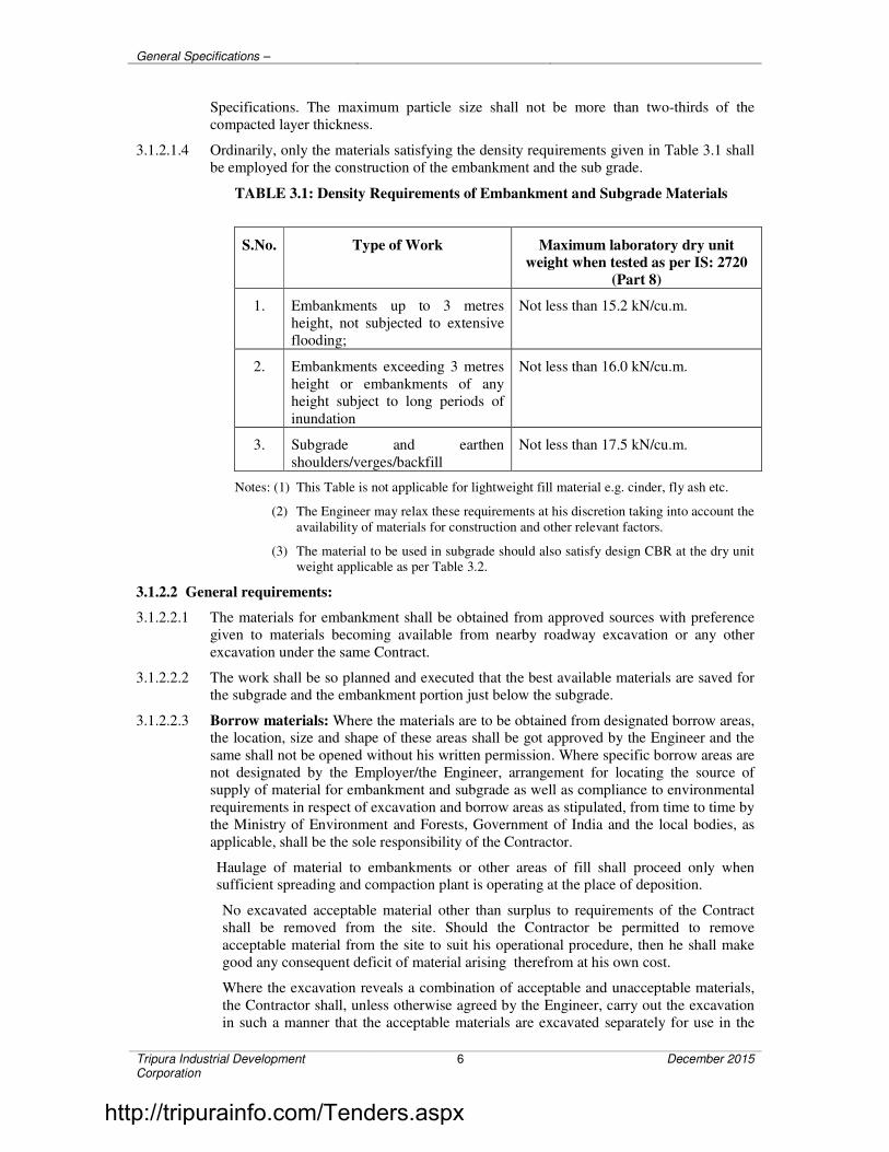
General Specifications –
Tripura Industrial Development Corporation
6 December 2015
Specifications. The maximum particle size shall not be more than two-thirds of the
compacted layer thickness.
3.1.2.1.4 Ordinarily, only the materials satisfying the density requirements given in Table 3.1 shall
be employed for the construction of the embankment and the sub grade.
TABLE 3.1: Density Requirements of Embankment and Subgrade Materials
S.No. Type of Work Maximum laboratory dry unit
weight when tested as per IS: 2720
(Part 8)
1. Embankments up to 3 metres
height, not subjected to extensive
flooding;
Not less than 15.2 kN/cu.m.
2. Embankments exceeding 3 metres
height or embankments of any
height subject to long periods of
inundation
Not less than 16.0 kN/cu.m.
3. Subgrade and earthen
shoulders/verges/backfill
Not less than 17.5 kN/cu.m.
Notes: (1) This Table is not applicable for lightweight fill material e.g. cinder, fly ash etc.
(2) The Engineer may relax these requirements at his discretion taking into account the
availability of materials for construction and other relevant factors.
(3) The material to be used in subgrade should also satisfy design CBR at the dry unit
weight applicable as per Table 3.2.
3.1.2.2 General requirements:
3.1.2.2.1 The materials for embankment shall be obtained from approved sources with preference
given to materials becoming available from nearby roadway excavation or any other
excavation under the same Contract.
3.1.2.2.2 The work shall be so planned and executed that the best available materials are saved for
the subgrade and the embankment portion just below the subgrade.
3.1.2.2.3 Borrow materials: Where the materials are to be obtained from designated borrow areas, the location, size and shape of these areas shall be got approved by the Engineer and the
same shall not be opened without his written permission. Where specific borrow areas are
not designated by the Employer/the Engineer, arrangement for locating the source of
supply of material for embankment and subgrade as well as compliance to environmental
requirements in respect of excavation and borrow areas as stipulated, from time to time by
the Ministry of Environment and Forests, Government of India and the local bodies, as
applicable, shall be the sole responsibility of the Contractor.
Haulage of material to embankments or other areas of fill shall proceed only when sufficient spreading and compaction plant is operating at the place of deposition.
No excavated acceptable material other than surplus to requirements of the Contract
shall be removed from the site. Should the Contractor be permitted to remove
acceptable material from the site to suit his operational procedure, then he shall make
good any consequent deficit of material arising therefrom at his own cost.
Where the excavation reveals a combination of acceptable and unacceptable materials,
the Contractor shall, unless otherwise agreed by the Engineer, carry out the excavation
in such a manner that the acceptable materials are excavated separately for use in the
http://tripurainfo.com/Tenders.aspx

General Specifications –
Tripura Industrial Development Corporation
7 December 2015
permanent works without contamination by the unacceptable materials. The acceptable
materials shall be stockpiled separately.
The Contractor shall ensure that he does not adversely affect the stability of excavation
or fills by the methods of stockpiling materials, use of plants or siting of temporary
buildings or structures.
The Contractor shall obtain representative samples from each of the identified borrow areas and have these tested at the site laboratory following a testing programme
approved by the Engineer. It shall be ensured that the subgrade material when
compacted to the density requirements as in Table 3.2 shall yield the design CBR value
of the subgrade.
TABLE 3.2: Compaction Requirements for Embankment and Subgrade
S.No. Type of Work / material Relative compaction as
percentage of max. laboratory
dry density as per IS: 2720
(Part 8)
1. Subgrade and earthen shoulders Not less than 97
2. Embankment Not less than 95
3. Expansive Clays subject to the
explanation in clause 3.1.2.1.1
a) Subgrade and 500 mm
portion just below the
subgrade
b) Remaining portion of
embankment
Not allowed
Not less than 90
The Contractor shall submit, at least 7 working days before commencement of
compaction, the following to the Engineer for approval:
(i) The values of maximum dry density and optimum moisture content obtained
in accordance with IS: 2720 (Part 7) or (Part 8), as the case may be,
appropriate for each of the fill materials he intends to use.
(ii) A graph of density plotted against moisture content from which each of the
values in (i) above of maximum dry density and optimum moisture content
were determined.
(iii) The Dry density-moisture content – CBR relationships for light, intermediate
and heavy compactive efforts (light corresponding to IS: 2720 (Part 7), heavy
corresponding to IS: 2720 (Part 8) and intermediate in-between the two) for
each of the fill materials he intends to use in the subgrade.
Once the above information has been approved by the Engineer, it shall form the
basis for compaction.
3.1.3 Construction Operations
3.1.3.1 Setting Out: After the site has been cleared the work shall be set out. The limits of
embankment/subgrade shall be marked by fixing batter pegs on both sides at regular intervals
as guides before commencing the earthwork the embankment/subgrade shall be suitably
prepared to design dimension so that surplus material may be trimmed, ensuring that the
http://tripurainfo.com/Tenders.aspx
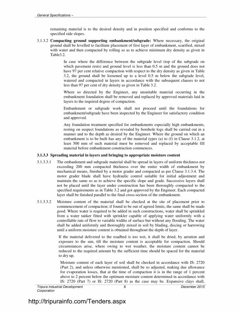
General Specifications –
Tripura Industrial Development Corporation
8 December 2015
remaining material is to the desired density and in position specified and conforms to the
specified side slopes.
3.1.3.2 Compacting ground supporting embankment/subgrade: Where necessary, the original
ground shall be levelled to facilitate placement of first layer of embankment, scarified, mixed
with water and then compacted by rolling so as to achieve minimum dry density as given in
Table3.2.
In case where the difference between the subgrade level (top of the subgrade on
which pavement rests) and ground level is less than 0.5 m and the ground does not
have 97 per cent relative compaction with respect to the dry density as given in Table
3.2, the ground shall be loosened up to a level 0.5 m below the subgrade level,
watered and compacted in layers in accordance with the subsequent clauses to not
less than 97 per cent of dry density as given in Table 3.2.
Where so directed by the Engineer, any unsuitable material occurring in the
embankment foundation shall be removed and replaced by approved materials laid in
layers to the required degree of compaction.
Embankment or subgrade work shall not proceed until the foundations for
embankment/subgrade have been inspected by the Engineer for satisfactory condition
and approved.
Any foundation treatment specified for embankments especially high embankments,
resting on suspect foundations as revealed by borehole logs shall be carried out in a
manner and to the depth as desired by the Engineer. Where the ground on which an
embankment is to be built has any of the material types (a) to (f) in Clause 3.1.2, at
least 500 mm of such material must be removed and replaced by acceptable fill
material before embankment construction commences.
3.1.3.3 Spreading material in layers and bringing to appropriate moisture content
3.1.3.3.1 The embankment and subgrade material shall be spread in layers of uniform thickness not
exceeding 200 mm compacted thickness over the entire width of embankment by
mechanical means, finished by a motor grader and compacted as per Clause 3.1.3.4. The
motor grader blade shall have hydraulic control suitable for initial adjustment and
maintain the same so as to achieve the specific slope and grade. Successive layers shall
not be placed until the layer under construction has been thoroughly compacted to the
specified requirements as in Table 3.2 and got approved by the Engineer. Each compacted
layer shall be finished parallel to the final cross-section of the embankment.
3.1.3.3.2 Moisture content of the material shall be checked at the site of placement prior to
commencement of compaction; if found to be out of agreed limits, the same shall be made
good. Where water is required to be added in such constructions, water shall be sprinkled
from a water tanker fitted with sprinkler capable of applying water uniformly with a
controllable rate of flow to variable widths of surface but without any flooding. The water
shall be added uniformly and thoroughly mixed in soil by blading, discing or harrowing
until a uniform moisture content is obtained throughout the depth of layer.
If the material delivered to the roadbed is too wet, it shall be dried, by aeration and
exposure to the sun, till the moisture content is acceptable for compaction. Should
circumstances arise, where owing to wet weather, the moisture content cannot be
reduced to the required amount by the sufficient time should be spaced for the material to dry up.
Moisture content of each layer of soil shall be checked in accordance with IS: 2720
(Part 2), and unless otherwise mentioned, shall be so adjusted, making due allowance
for evaporation losses, that at the time of compaction it is in the range of 1 percent
above to 2 percent below the optimum moisture content determined in accordance with
IS: 2720 (Part 7) or IS: 2720 (Part 8) as the case may be. Expansive clays shall,
http://tripurainfo.com/Tenders.aspx
General Specifications –
Tripura Industrial Development Corporation
9 December 2015
however be compacted at moisture content corresponding to the specified dry density,
but on the wet side of the optimum moisture content obtained from the laboratory
compaction curve.
After adding the required amount of water, the soil shall be processed by means of
graders, harrows, rotary mixers or as otherwise approved by the Engineer until the
layer is uniformly wet.
Clods or hard lumps of earth shall be broken to have a maximum size of 75mm when
being placed in the embankment and a maximum size of 50mm when being placed in
the subgrade.
3.1.3.3.3 Embankment and other areas of fill shall, unless otherwise required in the Contract or
permitted by the Engineer, be constructed evenly over their full width and their fullest
possible extent and the Contractor shall control and direct construction plant and
other vehicular traffic shall be made good by the contractor with material having the
same characteristics and strength as the material had before it was damaged.
Embankments and other areas of unsupported fills shall not be constructed with
steeper side slopes, or to greater widths than those shown in the Contract, except to
permit adequate compaction at the edges before trimming back, or to obtain the final
profile following any settlement of the fill and the underlying material.
Whenever fill is to be deposited against the face of a natural slope, or sloping
earthworks face including embankments, cuttings, other fills and excavations steeper
than 1 vertical on 4 horizontal, such faces shall be benched, immediately before
placing the subsequent fill.
All permanent faces of side slopes of embankments and other areas of fill formed
shall, subsequent to any trimming operations, be reworked and sealed to the
satisfaction of the Engineer by tracking a tracked vehicle, considered suitable by the
Engineer, on the slope or any other method approved by the Engineer.
3.1.3.4 Compaction: Only the compaction equipment approved by the Engineer shall be employed
to compact the different material types encountered during construction. Smooth
wheeled, vibratory, pneumatic tyred, sheepsfoot or pad foot rollers, etc. of suitable
size and capacity as approved by the Engineer shall be used for the different types
and grades of materials required to be compacted either individually or in suitable
combinations.
The compaction shall be done with the help of vibratory roller of 80 to 100 kN static
weight with plain or pad foot drum or heavy pneumatic tyred roller of adequate
capacity capable of achieving required compaction.
The Contractor shall demonstrate the efficacy of the equipment he intends to use by
carrying out compaction trials. The procedure to be adopted for these site trials shall first be submitted to the Engineer for approval.
Earthmoving plant shall not be accepted as compaction equipment nor shall the use of
a lighter category of plant to provide any preliminary compaction to assist the use of
heavier plant be taken into account.
Each layer of the material shall be thoroughly compacted to the densities specified in
Table 3.2. Subsequent layers shall be placed only after the finished layer has been
tested according to Clause 3.15.2.2 and accepted by the Engineer. The Engineer may
permit measurement of field dry density by a nuclear moisture/density gauge used in accordance with agreed procedure and the gauge is calibrated to provide results
identical to that obtained from tests in accordance with IS: 2720 (Part 28). A record of
the same shall be maintained by the Contractor.
http://tripurainfo.com/Tenders.aspx

General Specifications –
Tripura Industrial Development Corporation
10 December 2015
When density measurements reveal any soft areas in the embankment/
subgrade/earthen shoulders, further compaction shall be carried out as directed by the
Engineer. If in spite of that the specified compaction is not achieved, the material in
the soft areas shall be removed and replaced by approved material, compacted to the
density requirements and satisfaction of the Engineer.
3.1.3.5 Drainage: The surface of the embankment/subgrade at all times during construction shall be maintained at such a cross fall (not flatter than that required for effective drainage of
an earthen surface) as will shed water and prevent ponding.
3.1.3.6 Repairing of damages caused by rain/spillage of water: This work is carried out directed
by the Engineer before next layer is laid and refilled in layers and compacted using
appropriate mechanical means such as small vibratory roller, plate compactor or
power rammer to achieve the required density in accordance with Clause 3.1.3.4. If
the cut is not sufficiently wide for use of rollers, it shall be widened suitably to permit their use for proper compaction. Tests shall be carried out as directed by the Engineer
to ascertain the density requirements of the repaired area. The work of repairing the
damages including widening of the cut, if any, shall be carried out by the Contractor
at his own cost, including the arranging of machinery/equipment for the purpose.
3.1.3.7 Finishing operations: Finishing operations shall include the work of shaping and dressing
the shoulders/verge/roadbed and side slopes to conform to the alignment, levels,
cross-sections and dimensions shown on the drawings or as directed by the Engineer subject to the surface tolerance described in Table 3.24. Both the upper and lower
ends of the side slopes shall be rounded off to improve appearance and to merge the
embankment with the adjacent terrain.
The topsoil, removed and conserved earlier shall be spread over the fill slopes as per
directions of the Engineer to facilitate the growth of vegetation. Slopes shall be
roughened and moistened slightly prior to the application of the topsoil in order to
provide satisfactory bond. The depth of the topsoil shall be sufficient to sustain plant
growth, the usual thickness being from 75 mm to 150 mm.
Where directed, the slopes shall be turfed with sods or if seeding and mulching of
slopes is prescribed, this shall be done as per direction of the Engineer.
When earthwork operations have been substantially completed, the road area shall be
cleared of all debris, and ugly scars in the construction area responsible for
objectionable appearance eliminated.
3.1.3.8 Embankment and subgrade around structures: To avoid interference with the construction
of abutments, wing walls or return walls of culvert/bridge structures, the Contractor
shall, at points to be determined by the Engineer suspend work on embankment
forming approaches to such structures, until such time as the construction of the latter
is sufficiently advanced to permit the completion of approaches without the risk of
damage to the structure.
Unless directed otherwise, the filling around culverts, bridges and other structures up
to a distance of twice the height of the road from the back of the abutment shall be
carried out independent of the work on the main embankment. The fill material shall
not be placed against any abutment or wing wall, unless permission has been given by
the Engineer but in any case not until the concrete or masonry has been in position for
14 days. The embankment and subgrade shall be brought up simultaneously in equal
layers on each side of the structure to avoid displacement and unequal pressure. The
sequence of work in this regard shall be got approved from the Engineer.
The material used for backfill shall not be an organic soil or highly plastic clay
having plasticity index and liquid limit more than 20 and 40 respectively when tested
according to IS: 2720 (Part 5). Filling behind abutments and wing walls for all
http://tripurainfo.com/Tenders.aspx

General Specifications –
Tripura Industrial Development Corporation
11 December 2015
structures shall conform to the general guidelines given in Appendix 6 of IRC: 78
(Standard Specifications and Code of Practice for Road Bridges-Section VII) in
respect of the type of material, the extent of backfill, its laying and compaction etc.
The fill material shall be deposited in horizontal layers in loose thickness and
compacted thoroughly to the requirements of Table 3.2.
Where the provision of any filter medium is specified behind the abutment, the same shall be laid in layers simultaneously with the laying of fill material. The material
used for filter shall conform to the requirements for filter medium spelt out in Table
3.3. Unless otherwise specified in the Contract.
Where it may be impracticable to use conventional rollers, the compaction shall be
carried out by appropriate mechanical means such as small vibratory roller, plate
compactor or power rammer. Care shall be taken to see that the compaction
equipment does not hit or come too close to any structural member so as to cause any damage to them or excessive pressure against the structure.
3.1.3.9 Embankment construction under water: Where filling or backfilling is to be
placed under water, only acceptable granular material or rock shall be used unless
otherwise approved by the Engineer. Acceptable granular material shall consist
of graded, hard durable particles with maximum particle size not exceeding 75 mm.
The material should be non-plastic having uniformity coefficient of not less than
10. The material placed in open water shall be deposited by end tipping without compaction.
3.1.3.10 Earthwork for high embankment: In the case of high embankments, the Contractor
shall normally use the material from the specified borrow area. In case he desires to
use different material for his own convenience, he shall have to carry out necessary
soil investigations and redesign the high embankment at his own cost. The Contractor
shall then furnish the soil test data and design of high embankment for approval of the
Engineer, who reserves the right to accept or reject it.
If necessary, stage construction of fills and any controlled rates of filling shall be carried out in accordance with the Contract including installation of instruments and
its monitoring.
3.1.4 Plying of Traffic
Construction and other vehicular traffic shall not use the prepared surface of the
embankment and/or subgrade without the prior permission of the Engineer. Any
damage arising out of such use shall, however, be made good by the Contractor at his
own expense as directed by the Engineer.
3.1.5 Surface Finish and Quality Control of Work
The surface finish of construction of subgrade shall conform to the requirements of Table 3.26. Control on the quality of materials and works shall be exercised in
accordance with Clause 3.15.
3.1.6 Subgrade Strength
3.1.6.1 It shall be ensured prior to actual execution that the borrow area material to be used in
the subgrade satisfied the requirements of design CBR.
3.1.6.2 Subgrade shall be compacted and finished to the design strength consistent with other
physical requirements. The actual laboratory CBR values of constructed subgrade
shall be determined on undisturbed samples cut out form the compacted subgrade in
CBR mould fitted with cutting saw or on remoulded samples, compacted to the field
density at the field moisture content.
http://tripurainfo.com/Tenders.aspx

General Specifications –
Tripura Industrial Development Corporation
12 December 2015
3.1.7 Measurements for Payment
Earth embankment/subgrade construction shall be measured separately by taking
cross sections at intervals in the original position before the work starts and after its
completion and computing the volumes of earthwork in cubic metres by the method
of average end areas.
The measurement of fill material from borrow areas shall be the difference between the net quantities of compacted fill and the net quantities of suitable material brought
from roadway and drainage excavation. For this purpose, it shall be assumed that one
cu.m. of suitable material brought to site from road and drainage excavation form one
cu.m. of compacted fill and all building or shrinkage shall be ignored.
Construction of embankment under water shall be measured in cu.m.
Construction of high embankment with specified material and in specified manner
shall be measured in cu.m.
Stripping including storing and reapplication of topsoil shall be measured in cu.m.
Work involving loosening and recompacting of ground supporting embankment/subgrade shall be measured in cu.m.
Removal of unsuitable material at embankment/subgrade foundation and replacement
with suitable material shall be measure in cu.m.
Filter medium and backfill material behind abutments, wing walls and other retaining
structures shall be measured as finished work in position in cu.m.
3.1.8 Rates
3.1.8.1 The Contract unit rates for the items of embankment and subgrade construction shall
be payment in full for carrying out the required operations including full
compensation for:
(i) Cost of arrangement of land as a source of supply of material of required quantity for construction unless provided otherwise in the Contract;
(ii) Setting out;
(iii) Compacting ground supporting embankment/subgrade except where removal
and replacement of unsuitable material or loosening and recompacting is
involved.
(iv) Scarifying or cutting continuous horizontal benches 300 mm wide on side
slopes of existing embankment and subgrade as applicable.
(v) Cost of watering or drying of material in borrow areas and/or embankment
and subgrade during construction as required.
(vi) Spreading in layers, bringing to appropriate moisture content and compacting
to Specification requirements;
(vii) Shaping and dressing top and slopes of the embankment and subgrade
including rounding of corners;
(viii) Restricted working at sites of structures;
(ix) Working on narrow width of embankment and subgrade;
(x) Excavation in all soils from borrow pits/designated borrow areas including
clearing and grubbing and transporting the material to embankment and
subgrade site with all lifts and leads unless otherwise provided for in the
Contract;
http://tripurainfo.com/Tenders.aspx

General Specifications –
Tripura Industrial Development Corporation
13 December 2015
(xi) All labour, materials, tools, equipment and incidentals necessary to complete
the work to the Specifications;
(xii) Dewatering; and
(xiii) Keeping the embankment/completed formation free of water.
3.2 SURFACE/SUB SURFACE DRAINS
3.2.1 Scope
This work shall consist of constructing surface and / or sub-surface drains in
accordance with requirements of these specifications and to the lines, grades,
dimensions and other particulars shown on the drawings or as directed by the
Engineer. Schedule of work shall be so arranged that the drains are completed in
proper sequence with road works to ensure that no excavation of the completed road
works is necessary subsequently or any damage is caused to these works due to lack
of drainage.
3.2.2 Surface Drains
Surface drains shall be excavated to the specified lines, grades, levels and dimensions
as shown in drawings. The excavated material shall be removed from the area
adjoining the drains and if found suitable, utilized in embankment / subgrade construction. All unsuitable material shall be disposed of as directed.
The excavated bed and sides of the drains shall be dressed to bring these in close
conformity with the specified dimensions, levels and slopes.
Where so indicated, drains shall be lined or turfed with suitable materials in
accordance with details on the drawings.
All works on drain construction shall be planned and executed in proper sequence
with other works as approved by the engineer, with a view to ensuring adequate
drainage for the area and minimizing erosion / sedimentation.
The Special Specification for Storm Water Drainage also shall be referred to.
3.2.3 Sub-surface Drains
3.2.3.1 Scope: Sub-surface drains shall be of close-jointed perforated pipes, open-jointed
unperforated pipes, surrounded by granular material laid in a trench or aggregate
drains to drain the pavement courses or sub-surface drains designed using
Geosynthetic material and approved by the Engineer.
3.2.3.2 Materials
A. Pipe: Perforated pipes for the drains may be of metal / asbestos cement/
cement concrete / PVC, and unperforated pipes of vitrified clay / cement
concrete / asbestos cement. The type, size and grade of the pipe to be used
shall be as specified in the contract. In no case, however, shall the internal diameter of the pipe be less than 100mm. Holes for perforated pipes shall be
on one half of the circumference only and conform to the spacing indicated
on the drawings. Size of the holes shall not ordinarily be greater than half of
D85 size of the material surrounding the pipe, subject to minimum 3mm and
maximum 6mm. D85 stands for the size of the sieve that allows 85% of the
material to pass through it.
http://tripurainfo.com/Tenders.aspx

General Specifications –
Tripura Industrial Development Corporation
14 December 2015
B. Backfill material: Backfill material shall consist of sound, tough, hard,
durable particles of free draining sand-gravel material or crushed stone and
shall be free of organic material, clay balls or other deleterious matter. Unless
the contract specifies any particular gradings for the backfill material or
requires these to be designed on inverted filter criteria for filtration and permeability to the approval of the engineer, the backfill material shall be
provided on the following lines:
i. Where the soil met with in the trench is of fine grained type (e.g., silt,
clay or a mixture thereof), the backfill material shall conform to
Class I grading set out in Table 3.3.
ii. Where the soil met with in the trench is of coarse silt to medium sand
or sandy type, the backfill material shall correspond to Class II
grading of Table 3.3
iii. Where the soil met with in the trench is of gravelly sand, the backfill
material shall correspond to Class III grading of
Table 3.3.
Thickness of backfill material around the pipe shall be as shown on the drawings
subject to being at least 150mm around in all cases.
TABLE 3.3: Grading Requirements for Filter Material
Sieve designation Per cent passing by weight
Class I Class II Class III
53 mm - - 100
45 mm - - 97-100
26.5 mm - 100 -
22.4 mm - 95-100 58-10
11.2 mm 100 48-100 20-60
5.6 mm 92-100 28-54 4-32
2.8 mm 83-100 20-35 0-10
1.4 mm 59-96 - 0-5
710 micron 35-80 6-18 -
355 micron 14-40 2-9 -
180 micron 3-15 - -
90 micron 0-5 0-4 0-3
3.2.3.3 Trench Excavation: Trench for sub-surface drain shall be excavated to the specified
lines, grades and dimensions shown in the drawings provided that width of trench
at pipe level shall not be less than 450mm. The excavation shall begin at the outlet
end of the drain and proceed towards the upper end. Where unsuitable material
is met with at the trench bed, the same shall be removed to such depth as directed by the engineer and backfilled with approved material which shall be
thoroughly compacted to the specified degree.
3.2.3.4 Laying of pipe and Backfilling: Laying of pipe in the trench shall be started at the
outlet end and shall proceed towards the upper end, true to lines and grade
specified. Unless otherwise provided, longitudinal gradient of the pipe shall
not be less than 1 in 100.
http://tripurainfo.com/Tenders.aspx

General Specifications –
Tripura Industrial Development Corporation
15 December 2015
Before placing the pipe, backfill material of the required grading(s) shall be laid for
full width of the trench bed and compacted to a minimum thickness of 150mm or as
shown on the drawings. The pipe shall then be embedded firmly on the bed.
Perforated pipes, unless otherwise specified, shall be placed with their perforations
down to minimize clogging. The pipe sections shall be joined securely with
appropriate coupling fittings or bands.
Non-perforated pipes shall be laid as close as possible with the open joints wrapped
with suitable pervious material (like double layer of Hessian, suitable Geosynthetic
material of not less than 150mm width) to permit entry of water but prevent fines
entering the pipes. In the case of non-perforated pipes with bell end, the bell shall
face upgrade.
Upgrade end sections of the pipe installation shall be tightly closed by means of
concrete plugs or plugs fabricated from the same material as the pipe and securely
held in place to prevent entry of soil materials.
After the pipe installation has been completed and approved, backfill material of the
required grading(s) shall be placed over the pipe to the required level in horizontal
layers not exceeding 150mm in thickness and thoroughly compacted. The minimum
thickness of material above the top of the pipe shall be 300mm.
Unless otherwise provided, sub-surface drains not located below the road pavement
shall be sealed at the top by means of 150mm thick layer of compacted clay so as to
prevent percolation of surface water under the road layers.
3.2.3.5 Use of Geosynthetic in laying of pipe and backfilling: After excavating the trench for subsurface drain, the filter fabric shall be placed, the pipe installed and the
trench backfilled with permeable material according to dimensions and details
shown on the plans. Surfaces to receive filter fabric prior to placing shall be free of
loose or extraneous material and sharp objects that may damage the filter
fabric during installation. Adjacent rolls of the fabric shall be overlapped a
minimum of 450mm. The preceding roll shall overlap the following roll in the
direction the material is being spread.
Damage to the fabric resulting from Contractor’s vehicles, equipment or operations shall be replaced or repaired by the contractor at his expense.
3.2.3.6 Drain outlet: The outlet for a sub-drain shall not be under water or plugged with
debris but should be a free outlet discharging into a stream, culvert or open
protected with grate or screen. For a length of 500mm from the outlet end, the
trench for pipe shall not be provided with granular material but backfilled with
excavated soil and thoroughly compacted so as to stop water directly percolating
from the backfill material around the pipe. The pipe in this section shall not
have any perforations.
Trenches for aggregate drains shall be excavated to a minimum width of 300mm and
to the depth shown on the plans or ordered by the engineer. The bottom of the trench
shall be sloped to drain and shall be free from loose particles of soil. The trench shall
be excavated so as to expose clearly the granular pavement courses to be drained.
Aggregate for the drains shall be durable gravel, stone or slag and shall be free from
vegetable matter and other deleterious substances.
3.2.4 Measurement of Payment
Measurement for surface and sub-surface drains shall be per running metre length of
the drain. Disposal of surplus material beyond 1000 m shall be measured in cu.m.
http://tripurainfo.com/Tenders.aspx

General Specifications –
Tripura Industrial Development Corporation
16 December 2015
3.2.5 Rates
The Contract unit rates for surface and subsurface drains shall be payment in full for
all items such as excavation, dressing the sides and bottom; providing lining, turfing,
pitching, masonry, concrete and plastering; providing, laying and jointing pipes;
providing, laying and compacting backfill and bed of granular material; providing, fixing and painting of cover etc. including full compensation for all materials, labour,
tools, equipment and other incidentals to complete the work as shown on drawings
with all leads and lifts except for removal of unsuitable material for which the lead
shall be 1000 m. Provision of inlets, gratings, sumps, outlet pipes, bedding, disbursers
etc. wherever required shall be incidental to construction of drain. The Contract unit
rate for disposal of surplus and unsuitable material beyond the initial 1000 m lead
shall be full compensation for labour, tools, equipment and incidentals necessary on account of the additional haul.
3.3 GRANULAR SUB-BASE
3.3.1 Scope
This work shall consist of laying and compacting well-graded material on prepared
subgrade in accordance with the requirements of these Specifications. The material
shall be laid in one or more layers as sub-base or lower sub-base and upper sub-base
(termed as sub-base hereinafter) as necessary according to lines, grades and cross-
sections shown on the drawings or as directed by the Engineer.
3.3.2 Materials
3.3.2.1 The material to be used for the work shall be natural sand, moorum, gravel, crushed
stone, Jhama brick aggregate or combination thereof depending upon the grading
required. Materials like crushed slag, crushed concrete, brick metal and kankar may
be allowed only with the specific approval of the Engineer. The material shall be
free from organic or other deleterious constituents and conform to one of the
three grading given in Table 3.4.
3.3.2.2 While the gradings in Table 3.4 are in respect of close-graded granular sub-base
materials, one each for maximum particle size of 75 mm, 53 mm and 26.5 mm.
3.3.2.3 Physical requirements: The material shall have a 10 per cent fines value of 50 kN or
more (for sample in soaked condition) when tested in compliance with BS: 812 (Part
111). The water absorption value of the coarse aggregate shall be determined as per
IS: 2386 (Part 3); if this value is greater than 2 per cent, the soundness test shall be
carried out on the material delivered to site as per IS: 383. For Grading II and III
materials, the CBR shall be determined at the density and moisture content likely to
be developed in equilibrium conditions which shall be taken as being the density relating to a uniform air voids content of 5 per cent.
TABLE 3.4: Grading for Close-Graded Granular Sub-Base Materials
IS Sieve Designation
Per cent by weight passing the IS sieve
Grading I Grading II Grading III
75.0 mm 100 - -
53.0 mm 80–100 100 -
26.5 mm 55-90 70-100 100
http://tripurainfo.com/Tenders.aspx

General Specifications –
Tripura Industrial Development Corporation
17 December 2015
IS Sieve Designation
Per cent by weight passing the IS sieve
Grading I Grading II Grading III
9.50 mm 35-65 50-80 65-95
4.75 mm 25-55 40-65 50-80
2.36 mm 20-40 30-50 40-65
0.425 mm 10–25 15–25 20–35
0.075 mm 3-10 3-10 3-10
CBR value
(Minimum)
30 25 20
3.3.3 Strength of sub-base
It shall be ensured prior to actual execution that the material to be used in the sub-
base satisfies the requirements of CBR and other physical requirements when
compacted and finished.
When directed by the Engineer, this shall be verified by performing CBR tests in the
laboratory as required on specimens remoulded at field dry density and moisture
content any other tests for the “quality” of materials, as may be necessary.
3.3.4 Construction Operations
3.3.4.1 Preparation of subgrade: Immediately prior to the laying of sub-base, the subgrade
already finished to Clause 3.1 shall be prepared by removing all vegetation and other
extraneous matter, lightly sprinkled with water if necessary and rolled with two
passes of 80 – 100 kN smooth wheeled roller.
3.3.4.2 Spreading and Compacting: The sub-base material of grading specified in the
Contract shall be spread on the prepared subgrade with the help of a motor grader of
adequate capacity, its blade having hydraulic controls suitable for initial adjustment
and for maintaining the required slope and grade during the operation or other means
as approved by the Engineer.
When the sub-base material consists of combination of materials mentioned in Clause
3.3.2, mixing shall be done mechanically by the mix-in-place method.
Manual mixing shall be permitted only where the width of laying is not adequate for
mechanical operations, as in small-sized jobs. The equipment used for mix-in-place
construction shall be a rotavator or similar approved equipment capable of mixing the
material to the desired degree. If so desired by the Engineer, trial runs with the
equipment shall be carried out to establish its suitability for the work.
Moisture content of the loose material shall be checked in accordance with IS: 2720 (Part 2) and suitably adjusted by sprinkling additional water from a truck mounted or
trailer mounted water tank and suitable for applying water uniformly and at controlled
quantities to variable widths of surface or other means approved by the Engineer so
that, at the time of compaction, it is from 1 per cent above to 2 per cent below the
optimum moisture content corresponding to IS: 2720 (Part 8). While adding water,
due allowance shall be made for evaporation losses. After water has been added, the
material shall be processed by mechanical or other approved means like disc harrows, rotavators until the layer is uniformly wet.
Immediately thereafter, rolling shall start. If the thickness of the compacted layer does
not exceed 100 mm, a smooth wheeled roller of 80 to 100 kN weight may be used.
For a compacted single layer upto 225 mm the compaction shall be done with the
http://tripurainfo.com/Tenders.aspx

General Specifications –
Tripura Industrial Development Corporation
18 December 2015
help of a vibratory roller of minimum 80 to 100 kN static weight with plain drum or
pad foot-drum or heavy pneumatic tyred roller of minimum 200 to 300 kN weight
having a minimum tyre pressure of 0.7 MN/m2 or equivalent capacity roller capable
of achieving the required compaction. Rolling shall commence at the lower edge and
proceed towards the upper edge longitudinally for stretches of unidirectional crossfall and super-elevation, and shall commence at the edges and progress towards the centre
for stretches having crossfall on both sides.
Each pass of the roller shall uniformly overlap not less than one-third of the track
made in the preceding pass. During rolling, the grade and crossfall (camber) shall be
checked and any high spots or depressions, which become apparent, corrected by
removing or adding fresh material. The speed of the roller shall not exceed 5 km per
hour.
Rolling shall be continued till the density achieved is at least 98 per cent of the maximum dry density for the material determined as per IS: 2720 (Part 8). The
surface of any layer of material on completion of compaction shall be well closed,
free from movement under compaction equipment and from compaction planes,
ridges, cracks or loose material. All loose, segregated or otherwise defective areas
shall be made good to the full thickness of layer and re-compacted.
3.3.5 Surface Finish and Quality Control of Work
The surface finish of construction shall conform to the requirements of Clause 3.15.
Control on the quality of materials and works shall be exercised by the Engineer in
accordance with Section 3.15.
3.3.6 Arrangements for Traffic
During the period of construction, arrangement of traffic diversions shall be
maintained as per the direction of Engineer.
3.3.7 Measurements for Payment
Granular sub-base shall be measured as finished work in position in cubic metres.
The protection of edges of granular sub-base extended over the full formation as
shown in the drawing shall be considered incidental to the work of providing granular
sub-base and as such no extra payment shall be made for the same.
3.3.8 Rate
The Contract unit rate for granular sub-base shall be payment in full for carrying out the required operations including full compensation for:
(i) making arrangements for traffic diversions. Except for initial treatment to
verges, shoulders and construction of diversions;
(ii) furnishing all materials to be incorporated in the work including all royalities,
fees, rents where necessary and all leads and lifts;
(iii) all labour, tools, equipment and incidentals to complete the work to the
Specifications;
(iv) carrying out the work in part widths of road where directed;
(v) carrying out the required tests for quality control and
(vi) multiple handling of materials
3.4 WATER BOUND MACADAM
3.4.1 Scope
http://tripurainfo.com/Tenders.aspx

General Specifications –
Tripura Industrial Development Corporation
19 December 2015
This work shall consist of clean, crushed aggregates mechanically interlocked by
rolling and bonding together with screening, binding material where necessary and
water laid on a properly prepared subgrade/sub-base/base or existing pavement, as the
case may be and finished in accordance with the requirements of these Specifications
and in close conformity with the lines, grades, cross-sections and thickness as per approved plans or as directed by the Engineer.
It is, however, not desirable to lay water bound macadam on an existing thin black
topped surface without providing adequate drainage facility for water that would get
accumulated at the interface of existing bituminous surface and water bound
macadam.
3.4.2 Materials
3.4.2.1 Aggregates
3.4.2.1.1 Physical requirements: Coarse aggregates shall be either crushed or broken stone,
crushed slag, overburnt (Jhama) brick aggregate or any other naturally occurring
aggregates such as kankar and laterite of suitable quality. Material other than
crushed or broken stone and crushed slag shall be used in sub-base courses only.
If crushed gravel/shingle is used, not less then 90 per cent by weight of the gravel,
shingle pieces retained on 4.75 mm sieve shall have at least two fractured faces.
The aggregates shall conform to the physical requirements set forth in Table 3.5
The type and size range of the aggregate shall be specified in the Contract or shall
be as specified by the Engineer. If the water adsorption value of the coarse
aggregate is greater than 2 percent, the soundness test shall be carried out on the
material delivered to site as per IS: 2386 (Part 5)
3.4.2.1.2 Crushed or broken Stone: The crushed or broken stone shall be hard, durable and free
from excess flat, elongated, soft and disintegrated particles, dirt and other deleterious
material.
TABLE 3.5: Physical Requirements of Coarse Aggregates for Water Bound
Macadam for Sub-Base/Base Courses
Test Test Method Requirements
1. * Los Angeles Abrasion
value or *Aggregate
Impact value
IS: 2386 (Part-4)
IS: 2386 (Part-4) or IS: 5640
40 per cent (Max.)
30 per cent (Max.)
2. Combined Flakiness and
Elongation indices (Total)
IS: 2386 (Part – I) 30 per cent (Max.)**
* Aggregate may satisfy requirements of either of the two tests.
** Aggregates like brick metal, kankar, laterite etc. Which get softened in presence of
water shall tested for impact value under wet conditions in accordance with IS: 5640
*** The requirement of flakiness index and elongation index shall be enforced only in the
case of crushed broken stone and crushed slag
3.4.2.1.3 Crushed or broken Stone:
http://tripurainfo.com/Tenders.aspx

General Specifications –
Tripura Industrial Development Corporation
20 December 2015
Crushed slag shall be made from air-cooled blast furnace slag. It shall be of angular
shape, reasonably uniform in quality and density and generally free from thin, elongated
and soft pieces, dirt or other deleterious materials. The weight of crushed slag shall not be
less than 11.2 kN per m3 and the percentage of glossy material shall not be more than 20.
It should also comply with the following requirements:
1. Chemical stability : To comply with requirements of appendix of
BS:1047
2. Sulphur content : Maximum 2 per cent
3. Water absorption : Maximum 10 per cent
3.4.2.1.4 Overburnt (Jhama) brick aggregates:
Jhama brick aggregates shall be made from overburnt bricks or brick bats and be free
from dust and other objectionable and deleterious materials.
3.4.2.1.5 Grading requirements:
The coarse aggregates shall conform to one of the Grading given in Table 3.6 as
specified, provided, however, the use of Grading No. 1 shall be restricted to sub-base
courses only.
TABLE 3.6: Grading Requirements of Aggregates for Wet Bound Macadam
Gradin
g No.
Size Range IS Sieve Designation Per cent by
weight passing
1. 90 mm to 45 mm 125 mm
90 mm
63 mm
45 mm
22.4 mm
100
90-100
25-60
0-15
0-5
2. 63 mm to 45 mm 90 mm
63 mm
53 mm
45 mm
22.4 mm
100
90-100
25-75
0-15
0-5
3. 53 mm to 22.4
mm
63 mm
53 mm
45 mm
22.4 mm
11.2 mm
100
95-100
65-90
0-10
0-5
Note: The compacted thickness for a layer with Grading 1 shall be 100 mm while for
layer with other Gradings i.e., 2 & 3, it shall be 75 mm.
3.4.2.1.6 Screenings:
Screenings to fill voids in the coarse aggregate shall generally consist of the same
material as the coarse aggregate. However, where permitted, predominantly non-
http://tripurainfo.com/Tenders.aspx

General Specifications –
Tripura Industrial Development Corporation
21 December 2015
plastic material such as moorum or gravel (Other than rounded borne material)
may be used for this purpose provided liquid limit and plasticity index of
such material are below 20 and 6 respectively and fraction passing 75 micron
sieve does not exceed 10 per cent.
Screenings shall conform to the grading set forth in Table 3.6.1. The consolidated
details of quantity of screenings required for various grades of stone aggregates are
given in Table 3.6.2. The table also gives the quantities of materials (loose)
required for 10 m2 for sub-base/base compacted thickness of 100/75 mm
The use of screenings shall be omitted in the case of soft aggregates such as brick
metal, kankar, laterites, etc. As they are likely to get crushed to a certain extent under
rollers.
Table 3.6.1: Grading for Screenings
Grading
Classification
Size of Screenings IS Sieve
Designation
Percent by
weight passing
the IS Sieve
A 13.2 mm
13.2 mm
11.2 mm
5.6 mm
180 micron
100
95-100
15-35
0-10
B 11.2 mm
11.2 mm
5.6 mm
180 mm
100
90-100
15-35
Table 3.6.2: Approximate Quantities of Coarse Aggregates and Screenings Required
for 100/75 mm Compacted Thickness of Water Bound Macadam (WBM) Sub-Base
/Base Course for 10m2 Area
Screenings
Classific-
ation
Size Range Compacted
thickness
Loose
Qty.
Stone Screening Crushable Type such as
Moorum or Gravel
Grading
Classific-
ation & size
For. WBM
Sub-base/
base course
(Loose
quantity)
Grading
Classification
& size
Loose
Qty.
Grading 1 90 mm to
45 mm
100 mm 1.21 to
1.43 m3
Type A
13.2 mm
0.27 to
0.30 m3
Not uniform 0.30 to
0.32 m3
Grading 2 63 mm to
45 mm
75 mm 0.91 to
1.07 m3
Type A
13.2 mm
0.12 to
0.15 m3
-do- 0.22 to
0.24 m3
-do- -do- -do- -do- Type B
11.2 mm
0.20 to
0.22 m3
-do- -do-
Grading 3 53 mm to
22.4 mm
75 mm -do- -do- 0.18 to
0.21 m3
-do- -do-
3.4.2.1.7 Binding material
http://tripurainfo.com/Tenders.aspx

General Specifications –
Tripura Industrial Development Corporation
22 December 2015
Binding material to be used for water bound macadam as a filler material meant for
preventing ravelling, shall comprise of a suitable material approved by the Engineer
having a Plasticity Index (PI) value of less than 6 as determined in accordance with
IS: 2720 (Part-5).
The quantity of binding material where it is to be used, will depend on the type of
screenings. Generally, the quantity required for 75 mm compacted thickness of water bound macadam will be 0.06-0.09 m3/10m2 and 0.08-0.10m3/10m2 for 100 mm
compacted thickness.
The above mentioned quantities should be taken as a guide only, for estimation of
quantities of construction etc.
Application of binding materials may not be necessary when the screenings used are
of crushable type such as moorum or gravel.
3.4.3 Construction Operations
3.4.3.1 Preparation of base: The surface of the subgrade/sub-base/base to receive the water bound
macadam course shall be prepared to the specified lines and crossfall (camber) and made free
of dust and other extraneous material. Any ruts or soft yielding places shall be corrected in an approved manner and rolled until firm surface is obtained if necessary by sprinkling water.
Any sub-base/base/surface irregularities, where predominant, shall be made good by
providing appropriate type of profile corrective course (leveling course) to Clause 501 of
these Specifications.
As far as possible, laying water bound macadam course over an existing thick bituminous
layer may be avoided since it will cause problems of internal drainage of the pavement at the
interface of two courses. It is desirable to completely pick out the existing thin bituminous
weaning course where water bound macadam is proposed to be laid over it. However, where the intensity of rain is low and the interface drainage facility is efficient, water bound
macadam can be laid over the existing thin bituminous surface by cutting 50 mm x 50 mm
furrows at an angle of 45 degrees to the centre line of the pavement at one m intervals in the
existing road. The directions and depth of furrows shall be such that they provide adequate
bondage and also serve to drain water to the existing granular base course beneath the existing
thin bituminous surface.
3.4.3.2 Inverted Choke: If water bound macadam is to be laid directly over the subgrade,
without any other intervening pavement course, a 25 mm course of screenings
(Grading B) or coarse sand shall be spread on the prepared subgrade before
application of the aggregates is taken up. In case of a fine sand or silty or clayey
subgrade, it is advisable to lay 100 mm insulating layer of screening or coarse sand on
top of fine grained soil, the gradation of which will depend upon whether it is
intended to act as a drainage layer as well. As a preferred alternative to inverted
choke, appropriate geosynthetics performing functions of separation and drainage
may be used over the prepared subgrade as directed by the Engineer. Section 700 of
MoST specifications for Road and Bridge Works (IV Revision) shall be applicable for
use of Geosynthetics.
3.4.3.3 Spreading coarse aggregates: The coarse aggregates shall be spread uniformly and
evenly upon the prepared subgrade/sub-base/base to proper profile by using templates
places across the road about 6m apart, in such quantities that the thickness of each
http://tripurainfo.com/Tenders.aspx

General Specifications –
Tripura Industrial Development Corporation
23 December 2015
compacted layer is not more than 100 mm for Grading 1 and 75 mm for Grading 2
and 3, as specified in Clause 3.4.2.1.5. Wherever possible, approved mechanical
devices such as aggregate spreader shall be used to spread the aggregates uniformly
so as to minimise the need for manual rectification afterwards. Aggregates placed at
locations which are inaccessible to the spreading equipment, may be spread in one of
more layers by any approved means so as to achieve the specified results.
The spreading shall be done from stockpiles along the side of the roadway or directly from
vehicles. No segregation of large or fine aggregates shall be allowed and the coarse aggregate
as spread shall be uniform gradation with no pockets of fine material.
The surface of the aggregates spread shall be carefully checked with templates and all high or
low spots remedied by removing or adding aggregates as may be required. The surface shall
be checked frequently with a straight edge while spreading and rolling so as to ensure a finished surface as per approved Drawings.
The coarse aggregates shall not normally be spread more than 3 days in advance of the
subsequent construction operations.
3.4.3.4 Rolling: Immediately following the spreading of the coarse aggregate, rolling shall be started
with three wheeled power rollers of 80 to 100 kN capacity or tandem or vibratory rollers of 80
to 100 kN static weight. The type of roller to be used shall be approved by the Engineer based
on trial run.
Except on superelevated portions where the rolling shall proceed from inner edge to the outer,
rolling shall begin from the edges gradually progressing towards the centre. First the edge/edges shall be compacted with roller running forward and backward. The roller shall
then move inward parallel to the centre line of the road, in successive passes uniformly
lapping preceding tracks by at least one half width.
Rolling shall be discontinued when the aggregates are partially compacted with sufficient
void space in them to permit application of screenings. However, where screenings are not to
be applied, as in the case of crushed aggregates like brick metal, laterite and kankar,
compaction shall be continued until the aggregates are thoroughly keyed. During rolling,
slight sprinkling of water may be done, If necessary. Rolling shall not be done when the
subgrade is soft or yielding or when it causes a wave-like motion in the subgrade or subbase
course.
The rolled surface shall be checked transversely and longitudinally, with templates and any
irregularities corrected by loosening the surface, adding or removing necessary amount of
aggregates and re-rolling until the entire surface conforms to desired crossfall (camber) and
grade. In no case shall the use of screenings be permitted to make up depressions.
Material which gets crushed excessively during compaction or becomes segregated shall be
removed and replaced with suitable aggregates.
It shall be ensured that shoulders are built up simultaneously along with water bound
macadam courses as per specification.
3.4.4 Application of Screening: After the coarse aggregate has been rolled to Clause 3.4.3.4,
screenings to completely fill the interstices shall be applied gradually over the surface. These
shall not be damp or wet at the time of application. Dry rolling shall be done while the
http://tripurainfo.com/Tenders.aspx

General Specifications –
Tripura Industrial Development Corporation
24 December 2015
screening are being spread so that vibrations of the roller cause them to settle into the voids of
the coarse aggregate. The screenings shall not be dumped in piles but be spread uniformly in
successive thin layers either by the spreading motions of hand shovels or by mechanical
spreaders, or directly from tipper with suitable grit spreading arrangement. Tipper operating
for spreading the screenings shall be so driven as not to disturb the coarse aggregate.
The screenings shall be applied at a slow and uniform rate (in three or more applications) so as to ensure filling of all voids. This shall be accompanied by dry rolling and brooming with
mechanical brooms, hand brooms or both. In no case shall the screenings be applied so fast
and thick as to form cakes or ridges on the surface in such a manner as would prevent filling
of voids or prevent the direct bearing of the roller on the coarse aggregate. These operations
shall continue until no more screenings can be forced into the voids of the coarse aggregate.
The spreading, rolling, and brooming of screenings shall be carried out in only such lengths of
the road which could be completed within one day’s operation
3.4.5 Sprinkling of water and grouting
After the screenings have been applied, the surface be copiously sprinkled with water, swept
and rolled. Hand brooms shall be used to sweep the wet screenings into voids and to distribute
them evenly. The sprinkling, sweeping and rolling operation shall be continued, with
additional screenings applied as necessary until the coarse aggregate has been thoroughly keyed, well-bonded and firmly set in its full depth and a grout has been formed of screenings.
Care shall be taken to see that the base or subgrade does not get damaged due to the addition
of excessive quantities of water during construction.
In case of lime treated soil sub-base, construction of water bound macadam on top of it can
cause excessive water to flow down to the lime treated sub-base before it has picked up
enough strength (is still “green”) and thus cause damage to the sub-base layer. The laying of
water bound macadam layer in such cases shall be done after the sub-base attains adequate
strength, as directed by the Engineer.
3.4.6 Application of Binding Material
After the application of screenings in accordance with Clauses 3.4.4 and 3.4.5 the binding
material where it is required to be used (Clause 3.4.2.1.7) shall be applied successively in two
or more thin layers at a slow and uniform rate. After each application, the surface shall be
copiously sprinkled with water, the resulting slurry swept in with hand brooms, or mechanical
brooms to fill the voids properly, and rolled during which water shall be applied to the wheels
of the rollers if necessary to wash down the binding material sticking to them. These
operations shall continue until the resulting slurry after filling of voids, forms a wave ahead of
the wheels of the moving roller.
3.4.7 Setting and Drying
After the final compaction of water bound macadam course, the pavement shall be allowed to
dry overnight. Next morning hungry spots shall be filled with screenings or binding material
as directed, lightly sprinkled with water if necessary and rolled. No traffic shall be allowed on
the road until the macadam has set. The Engineer shall have the discretion to stop hauling
traffic from using the completed water bound macadam course, if in his opinion it would cause excessive damage to the surface.
The compacted water bound macadam course should be allowed to completely dry and set
before the next pavement course is laid over it
3.4.8 Surface Finish and Quality Control of Work
http://tripurainfo.com/Tenders.aspx

General Specifications –
Tripura Industrial Development Corporation
25 December 2015
The surface finish of construction shall conform to the requirements of Section 902 of MoST
Specifications for Road and Bridge Works (IV Revision).
Control on the quality of materials and works shall be exercised by the Engineer in
accordance with Section 900 of MoST Specifications for Road and Bridge Works (IV
Revision).
The water bound macadam work shall not be carried out when the atmospheric temperature is
less than 0 degree centigrade in the shade.
3.4.9 Reconstruction of Defective macadam
The finished surface of water bound macadam shall conform to the tolerance of surface
regularity as prescribed in Section 902 of MoST Specifications for Road and Bridge Works
(IV Revision). However, where the surface irregularity of the course exceeds the tolerances or where the course is otherwise defective due to subgrade soil mixing with the aggregates, the
course to its full thickness shall be scarified over the affected area, reshaped with added
material or removed and replaced with fresh material as applicable and recompacted. In no
case shall depressions be filled up with screenings or binding material.
3.4.10 Arrangement for Traffic
During the period of construction, the arrangement of traffic shall be done as per MoRT&H
clause 112.
3.4.11 Measurements for Payment
Water bound macadam shall be measured as finished work in position in cubic
metres.
3.4.12 Rate
The Contract unit rate for water bound macadam sub-base/base course shall be payable in full
for carrying out the required operations including full compensation for all components listed
in Clause 3.3.8 including arrangement of water used in the work as approved by the Engineer.
3.5 CEMENT CONCRETE KERB AND KERB WITH CHANNEL
3.5.1 Scope
This work shall consist of constructing cement concrete kerbs and kerbs with channel in the
central median and/or along the footpaths or separators in conformity with the lines, levels
and dimensions as specified in the drawings.
3.5.2 Materials
Kerbs and kerb with channel shall be provided in cement concrete of Grade M20 in
accordance with the Specifications.
3.5.3 Type of Construction
These shall be cast-in-situ construction with suitable kerb casting machine in all situations except at locations where continuous casting with equipment is not practicable. In those
situations, precast concrete blocks shall be used.
3.5.4 Equipment
http://tripurainfo.com/Tenders.aspx
General Specifications –
Tripura Industrial Development Corporation
26 December 2015
A continuous kerb casting equipment of adequate capacity and controls, capable of laying the
kerbs in required cross-sections and producing a well-compacted mass of concrete free of
voids and honeycombs, shall be used.
3.5.5 Construction Operations
3.5.5.1 Kerb shall be laid on firm foundation of minimum 150 mm thickness of cement concrete of
M10 grade cast in-situ or one extended width and pavement. The foundation shall have a projection of 50 mm beyond the kerb stone. Before laying the foundation of lean concrete, the
base shall be levelled and slightly watered to make it damp.
3.5.5.2 In the median lengths. In the portions where footpath is provided and/or the slope of the
carriageway is towards median (as in case of super elevated portions), there shall be sufficient
gap/recess left in the kerb to facilitate portions in the straight reaches, the kerb shall be cast in
continuous drainage openings.
3.5.5.3 After laying the kerbs and just prior to hardening of the concrete, saw cut grooves shall be
provided at 5 m intervals or as specified by the Engineer.
3.5.5.4 Kerbs on the drainage ends such as along the footpath or the median in super elevated portions shall be cast with monolithic concrete channels as indicated in drawings. The slope
of the channel towards drainage pipes shall be ensured for efficient drainage of the road
surface.
3.5.5.5 Vertical and horizontal tolerances with respect to true line and level shall be ± 6 mm.
3.5.6 Measurements for Payment
Cement concrete kerb/kerb with channel shall be measured in linear metre for the complete
item of work.
Foundation of kerb, where separately provided shall be measured in linear metre for complete
item of work.
3.5.7 Rates
The Contract unit rates for cement concrete kerb/kerb with channel and foundation for kerb
shall be payment in full compensation for furnishing all materials, labour, tools, equipment
for construction and other incidental cost necessary to complete the work.
3.6 FOOTPATHS AND SEPARATORS
3.6.1 Scope
The work shall consist of constructing footpaths and/or separators at locations as specified in
the drawings or as directed by the Engineer. The lines, levels and dimensions shall be as per
the drawings. The scope of the work shall include provision of all drainage arrangements as shown in the drawings or as directed.
3.6.2 Materials
The footpaths and separators shall be constructed with any of the following types:
a) Cast-in-situ cement concrete of Grade M20 as per the Specifications.
b) Precast cement concrete blocks/tiles of Grade M20 as per the Specifications.
The minimum thickness of the cement concrete block/tile shall be 25 mm and
minimum size shall be 300 mm × 300 mm.
c) Natural stone slab cut and dressed from stone of good and sound quality,
uniform in texture, free from defects and at least equal to a sample submitted
by the Contractor and approved by the Engineer. The minimum thickness of
the natural stone slab shall be 25 mm and minimum size shall be 300 mm ×
300 mm.
http://tripurainfo.com/Tenders.aspx

General Specifications –
Tripura Industrial Development Corporation
27 December 2015
3.6.3 Construction Operations
3.6.3.1 Drainage pipes below the footpath originating from the kerbs shall be first laid in the required
slope and connected to the drains/sumps/storm water drain/drainage chutes as per provisions
of the drawings, or as specified.
3.6.3.2 Portion on back side of kerbs shall be filled and compacted with granular sub-base material as
per Clause 3.3 of the Specifications in specified thickness.
3.6.3.3 The base shall be prepared and finished to the required lines, levels and dimensions as
indicated in the drawings with the following:
a) Minimum 150 mm thick, compacted granular sub-base material as per Clause
3.3 of the Specifications.
b) Minimum 25 mm thick cement concrete of Grade M 15.
Over the prepared base, precast concrete blocks/tiles/natural stone slabs and/or cast-
in-situ slab shall be set/laid as described in Clauses 3.6.3.4 and 3.6.3.5.
3.6.3.4 Precast cement concrete blocks/tiles/natural stone slab: The blocks/tiles/slabs shall be set on a
layer of average 12 mm thick cement sand mortar (1:3) laid on prepared base in such a way
that there is no rocking. The gaps between the blocks/tiles/slabs shall not be more than 12 mm
and shall be filled with cement-sand mortar (1:3).
3.6.3.5 Cast-in-situ cement concrete: The minimum thickness of the cement concrete shall be 25 mm
and it shall be cast on the prepared base in panels of specified size in a staggered manner.
Construction joints shall be provided as directed.
3.6.4 Measurements for Payment
Footpaths and separators shall be measured in sq.metre between inside of kerbs.
3.6.5 Rates
Contract unit rates shall be inclusive of full compensation of all labour, materials, tools,
equipment and incidentals to construction of footpaths. Cost of providing pipes and arrangement for their discharge into appropriate drainage channels shall be incidental to the
construction of footpaths.
3.7 PRIME COAT OVER GRANULAR BASE
3.7.1 Scope
This work shall consist of the application of a single coat of low viscosity liquid bituminous
material to a porous granular surface preparatory to the superimposition of bituminous
treatment or mix.
3.7.2 Materials
3.7.2.1 Primer: The choice of a bituminous primer shall depend upon the porosity characteristics of
the surface to be primed as classified in IRC:16. These are:
i) Surfaces of low porosity; such as wet mix macadam and water bound
macadam,
ii) Surfaces of medium porosity; such as cement stabilized soil base,
iii) Surface of high porosity; such as a gravel base.
3.7.2.2 Primer viscosity: The type and viscosity of the primer shall comply with the requirements of
IS 8887, as sampled and tested for bituminous primer in accordance with these standards.
Guidance on viscosity and rate of spray is given in Table 3.7.
TABLE 3.7: Viscosity Requirement and Quantity of Liquid Bituminous Primer
http://tripurainfo.com/Tenders.aspx
General Specifications –
Tripura Industrial Development Corporation
28 December 2015
Type of surface Kinematic Viscosity
of Primer at 60°C
(Centistokes)
Quantity of Liquid
Bituminous Material
per 10 Sq.m.
(kg)
Low porosity 30 - 60 6 to 9
Medium porosity 70 – 140 9 to 12
High porosity 250 – 500 12 to 15
3.7.2.3 Choice of primer: The primer shall be bitumen emulsion, complying with IS 8887 of a type
and grade as specified in the Contract or as directed by the Engineer. The use of medium
curing cutback as per IS 217 shall be restricted only for sites at sub-zero temperatures or for
emergency applications as directed by the Engineer.
3.7.3 Weather and Seasonal Limitations
Bituminous primer shall not be applied to a wet surface (see 3.7.4.2) or during a dust storm or
when the weather is foggy, rainy or windy or when the temperature in the shade is less than
10°C. Surfaces which are to receive emulsion primer should be damp, but no free or standing water shall be present.
3.7.4 Construction
3.7.4.1 Equipment: The primer distributor shall be a self-propelled or towed bitumen pressure
sprayer equipped for spraying the material uniformly at specified rates and temperatures.
Hand spraying of small area, inaccessible to the distributor, or in narrow strips shall be
sprayed with a pressure hand sprayer, or as directed by the Engineer.
3.7.4.2 Preparation of road surface: The surface to be primed shall be prepared in accordance with
Table 3.26 as appropriate. Immediately prior to applying the primer the surface shall be carefully swept clean of dust and loose particles, care being taken not to disturb the
interlocked aggregate. This is best achieved when the surface layer is slightly moist (lightly
sprayed with water and the surface allowed to dry) and the surface should be kept moist until
the primer is applied.
3.7.4.3 Application of bituminous primer: The viscosity and rate of application of the primer shall
be as specified in the Contract, or as determined by site trials carried out as directed by the
Engineer. The bituminous primer shall be sprayed uniformly. The method for application of
the primer will depend on the type of equipment to be used, size of nozzles, pressure at the spray bard and speed of forward movement. The Contractor shall demonstrate at a spraying
trial, that the equipment and method to be used is capable of producing a uniform spray,
within the tolerances specified.
3.7.4.4 Curing of primer and opening to traffic: A primed surface shall be allowed to cure for at
least 24 hours or such other period as is found to be necessary to allow all the volatiles to
evaporate before any subsequent surface treatment or mix is laid. Any unabsorbed primer
shall first be blotted with an application of sand, using the minimum quantity possible. A primed surface shall not be opened to traffic other than that necessary to lay the next course.
A very thin layer of clean sand may be applied to the surface of the primer, to prevent the
primer picking up under the wheels of the paver and the trucks delivering bituminous material
to the paver.
3.7.4.5 Tack coat: Over the primed surface, a tack coat should be applied in accordance with Clause
3.8 if required and directed by the Engineer.
3.7.5 Quality Control of Work
For control of the quality of materials supplied and the works carried out, the relevant
provisions of Section 3.15 shall apply.
http://tripurainfo.com/Tenders.aspx

General Specifications –
Tripura Industrial Development Corporation
29 December 2015
3.7.6 Arrangements for Traffic
During construction operations, arrangements for traffic diversion shall be made in
accordance with the direction of the Engineer.
3.7.7 Measurement for Payment
Prime coat shall be measured in terms of surface area of application in square metres.
3.7.8 Rate
The contract unit rate for prime coat as described in Clause 3.7.7 shall be payment in full for
carrying out the required operations including full compensation for all components listed in Clause 3.7.4 and as applicable to the work specified in these Specifications. Payment shall be
made on the basis of the provision of prime coat at an application rate of 0.6 kg per square
metre, with adjustment, plus or minus, for the variation between this amount and the actual
amount approved by the Engineer after the preliminary trials referred to in Clause 3.7.4.3.
3.8 TACK COAT
3.8.1 Scope
This work shall consist of the application of a single coat of low viscosity liquid bituminous
material to an existing bituminous road surface preparatory to the superimposition of a
bituminous mix, when specified in the Contract or instructed by the Engineer.
3.8.2 Materials
3.8.2.1 Binder: The binder used for tack coat shall be bitumen emulsion complying with IS 8887 of a
type and grade as specified in the Contract or as directed by the Engineer. The use of cutback
bitumen as per IS 217 shall be restricted only for sites at sub-zero temperatures or for
emergency applications as directed by the Engineer.
3.8.3 Weather and Seasonal Limitations
Bituminous material shall not be applied to a wet surface or during a dust storm or when the
weather is foggy, rainy or windy or when the temperature in the shade is less than 10°C. Where the tack coat is of cutback bitumen, the surface shall be dry.
3.8.4 Construction
3.8.4.1 Equipment: The tack coat distributor shall be a self-propelled or towed bitumen pressure
sprayer, equipped for spraying the material uniformly at a specified rate. Hand spraying of
small areas, inaccessible to the distributor, or in narrow strips, shall be sprayed with a
pressure hand sprayer, or as directed by the Engineer.
3.8.4.2 Preparation of base: The surface on which the tack coat is to be applied shall be clean and
free from dust, dirt, and any extraneous material, and be otherwise prepared in accordance
with the requirements of Clause 3.15 as appropriate. Immediately before the application of the
tack coat, the surface shall be swept clean with a mechanical broom, and high pressure air jet,
or by other means as directed by the Engineer.
3.8.4.3 Application of tack coat: The application of tack coat shall be at the rate specified in the
Contract, and shall be applied uniformly. If rate of application of Tack Coat is not specified in
the contract then it shall be at the rate specified in Table 3.8. The normal range of spraying
temperature for a bituminous emulsion shall be 20°C to 70°C and for cutback, 50°C to 80°C
if RC-70 is used. The method of application of the tack coat will depend on the type of
equipment to be used, size of nozzles, pressure at the spray bar, and speed of forward
movement. The Contractor shall demonstrate at a spraying trial, that the equipment and
method to be used is capable of producing a uniform spray, within the tolerances specified.
TABLE 3.8: Rate of Application of Tack Coat
http://tripurainfo.com/Tenders.aspx

General Specifications –
Tripura Industrial Development Corporation
30 December 2015
Where the material to receive an overlay is a freshly laid bituminous layer, that has not been subjected to traffic, or contaminated by dust, a tack coat is not mandatory where the overlay is
completed within two days.
3.8.4.4 Curing of tack coat: The tack coat shall be left to cure until all the volatiles have evaporated
before any subsequent construction is started. No plant or vehicles shall be allowed on the
tack coat other than those essential for the construction.
3.8.5 Quality Control of Work
For control of the quality of materials supplied and the works carried out, the relevant
provisions of Section 3.15 shall apply.
3.8.6 Arrangements for Traffic
During the period of construction, arrangements for traffic diversion shall be made as directed.
3.8.7 Measurement for Payment
Tack coat shall be measured in terms of surface area of application in square metres.
3.8.8 Rate
The contract unit rate for tack coat shall be payment in full for carrying out the required
operations including for all components listed in Clause 3.8.4 and as applicable to the work
specified in these Specifications. The rate shall cover the provision of tack coat at 0.2 kg per
square metre, with the provision that the variance in actual quantity of bitumen used will be
assessed and the payment adjusted accordingly.
3.9 BITUMINOUS MACADAM
3.9.1 Scope
This work shall consist of construction in a single course having 50 mm to 100 mm thickness
or in multiple courses of compacted crushed aggregates premixed with a bituminous binder
on a previously prepared base to the requirements of these Specifications. Bituminous
macadam is more open graded than the dense graded bituminous materials described in
Clauses 3.10, 3.11, 3.12.
3.9.2 Materials
3.9.2.1 Bitumen: The bitumen shall be paving bitumen of Penetration Grade complying with Indian
Standard Specifications for “Paving Bitumen” IS: 73, and of the penetration indicated in
Table 3.10.
3.9.2.2 Coarse aggregates: The coarse aggregates shall consist of crushed rock, crushed gravel or
other hard material retained on the 2.36 mm sieve. They shall be clean, hard, durable, of
Type of Surface Quantity of liquid bituminous
material in Kg per sq.m. area
i) Normal bituminous surfaces 0.20 to 0.25
ii) Dry and hungry bituminous surfaces 0.25 to 0.30
iii) Granular surfaces treated with primer 0.25 to 0.30
iv) Non bituminous surfaces
a) Granular base (not primed)
b) Cement concrete pavement
0.35 to 0.40
0.30 to 0.35
http://tripurainfo.com/Tenders.aspx
General Specifications –
Tripura Industrial Development Corporation
31 December 2015
cubical shape, free from dust and soft or friable matter, organic or other deleterious matter.
Where the Contractor’s selected source of aggregates have poor affinity for bitumen, as a
condition for the approval of that source, the bitumen shall be treated with approved anti-
stripping agents, as per the manufacturer’s recommendations, without additional payment.
Before approval of the source, the aggregates shall be tested for stripping.
The aggregates shall satisfy the physical requirements set forth in Table 3.9.
Where crushed gravel is proposed for use as aggregate, not less than 90% by weight of the
crushed material retained on the 4.75 mm sieve shall have at least two fractured faces.
3.9.2.3 Fine aggregates: Fine aggregates shall consist of crushed or naturally occurring mineral
material, or a combination of the two, passing 2.36mm sieve and retained on the 75 micron
sieve. They shall be clean, hard, durable, dry and free from dust, and soft or friable matter,
organic or other deleterious matter.
TABLE 3.9: Physical Requirements for Coarse Aggregates for Bituminous
Macadam
Property Test Specification
Cleanliness Grain size analysis1 Max 5% passing
0.075mm sieve
Particle shape Flakiness and Elongation Index
(Combined)2
Max 30%
Strength* Los Angeles Abrasion Value3
Aggregate Impact Value
3
Max 40%
Max 30%
Durability Soundness:4
Sodium Sulphate
Magnesium Sulphate
Max 12%
Max 18%
Water Absorption Water absorption5 Max 2%
Stripping Coating and Stripping of Bitumen
Aggregate Mixtures6
Minimum retained
coating 95%
Water Sensitivity7 Retained Tensile Strength Min 80%
Notes: 1. IS: 2386 Part 1 4. IS: 2386 Part 5
2. IS: 2386 Part I 5. IS: 2386 Part 3
(the elongation test to be done only on non-flaky aggregate in the sample)
3. IS: 2386 Part 4* 6. IS: 6241
7. The water sensitivity test is only to be carried out if the minimum retained coating
in the stripping test is less than 95%.
*Aggregate may satisfy requirements of either of these two tests.
3.9.2.4 Aggregate grading and binder content: When tested in accordance with IS: 2386 Part I
(wet sieving method), the combined aggregate grading for the particular mixture shall fall
within the limits shown in Table 3.10 for the grading specified in the Contract. The type and
quantity of bitumen, and appropriate thickness, are also indicated for each mixture type.
3.9.2.5 Proportioning of material: The aggregates shall be proportioned and blended to produce a
uniform mixture complying with the requirements of Table 3.10. The binder content shall be
http://tripurainfo.com/Tenders.aspx

General Specifications –
Tripura Industrial Development Corporation
32 December 2015
within a tolerance of ± 0.3 per cent by weight of total mixture when individual specimens are
taken for quality control tests in accordance with the provisions of Table 3.28.
3.9.3 Construction Operations
3.9.3.1 Weather and seasonal limitations: Laying shall be suspended while free-standing water is
present on the surface to be covered, or during fog, rain and dust storms or when the
surrounding temperature is below 10°C or when wind speed exceed 40 km/hr at 2m height.
TABLE 3.10: Composition of Bituminous Macadam
Mix designation
Nominal aggregate
size Layer thickness
IS Sieve (mm)
Grading 1
40 mm
80 - 100 mm
Cumulative % by weight of
total aggregate passing
Grading 2
19 mm
50 - 75 mm
45 100
37.5 90 – 100
26.5 75 – 100 100
19 - 90 – 100
13.2 35 – 61 56 – 88
4.75 13 – 22 16 – 36
2.36 4 – 19 4 – 19
0.3 2 – 10 2- 10
0.075 0 – 8 0 – 8
Bitumen content, %
by weight of total
mixture1
3.1 – 3.4 3.3 – 3.5
Bitumen grade 35 to 90 35 to 90
Notes: 1. Appropriate bitumen contents for conditions in cooler areas of India may be up to
0.5% higher subject to the approval of the Engineer.
3.9.3.2 Preparation of the base: The base on which bituminous macadam is to be laid shall be
prepared, shaped and compacted to the required profile in accordance with Clause 3.15 as
appropriate, and a prime coat, shall be applied in accordance with Clause 3.7 where specified,
or as directed by the Engineer.
3.9.3.3 Tack coat: A tack coat in accordance with Clause 3.8 shall be applied as required by the
Contract documents, or as directed by the Engineer.
3.9.3.4 Preparation and transportation of the mixture: The bituminous mix materials shall be
prepared in a hot mix plant of adequate capacity and capable of yielding a mix of proper and
uniform quality and shall be transported to site in clean insulated vehicles and shall be
covered while in transit or awaiting tipping.
3.9.3.5 Spreading: Except in areas where paver cannot access bituminous materials shall be spread,
levelled and tamped by an approved self-propelled paving machines. The materials shall be
supplied continuously to the paver and laid without delay.
TABLE 3.11: Manufacturing and Rolling Temperatures
http://tripurainfo.com/Tenders.aspx

General Specifications –
Tripura Industrial Development Corporation
33 December 2015
Bitumen
Penetration
Bitumen
Mixing (°C)
Aggregate
Mixing (°C)
Mixed
Material (°C)
Rolling (°C) Laying (°C)
35 160 – 170 160 – 175 170 Maximum 100 Minimum 130 Minimum
65 150 – 165 150 -170 165 Maximum 90 Minimum 125 Minimum
90 140 – 160 140 -165 155 Maximum 80 Minimum 115 Minimum
3.9.3.6 Rolling: Compaction shall be carried out 8 to 10 kN static or vibratory roller or pneumatic
roller at temperature specified in Table 3.11.
Rolling shall be continued until the specified density is achieved, or where no density is
specified, until there is no further movement under the roller. The required frequency of
testing is defined in Clause 3.15.
3.9.4 Surface Finish and Quality Control of Work
The surface finish of the completed construction shall conform to the requirements of Table
3.26. For control of the quality of materials supplied and the works carried out, the relevant
provisions of Clause 3.15 shall apply.
3.9.5 Protection of the Layer
The bituminous macadam shall be covered with either the next pavement course or wearing
course, as the case may be, within a maximum of forty-eight hours. If there is to be any delay,
the course shall be covered by a seal coat before opening to any traffic. The seal coat in such
cases shall be considered incidental to the work and shall not be paid for separately.
3.9.6 Arrangements for Traffic
During the period of construction, arrangements for traffic diversions shall be made as
directed.
3.9.7 Measurement for Payment
Bituminous macadam shall be measured as finished work in cubic metres, or by weight in
metric tones, where used as regulating course, or square metres at the specified thickness as indicated in the Contract or shown on the drawings, or as otherwise directed by the Engineer.
3.9.8 Rate
The contract unit rate for bituminous macadam shall be payment in full for carrying out the
required operations as specified.
3.10 DENSE GRADED BITUMINOUS MACADAM
3.10.1 Scope
This clause specifies the construction of Dense Graded Bituminous Macadam, (DBM), for use
mainly, but not exclusively, in base/binder and profile corrective courses. DBM is also
intended for use as road base material. This work shall consist of construction in a single or
multiple layers of DBM on a previously prepared base or sub-base. The thickness of a single
layer shall be 50 mm to 100 mm.
3.10.2 Materials
3.10.2.1 Bitumen: The bitumen shall be paving bitumen of Penetration Grade complying with Indian
Standard Specifications for “Paving Bitumen” IS: 73, and of the penetration indicated in
Table 3.14 for dense bitumen macadam, or as otherwise specified in the Contract.
http://tripurainfo.com/Tenders.aspx
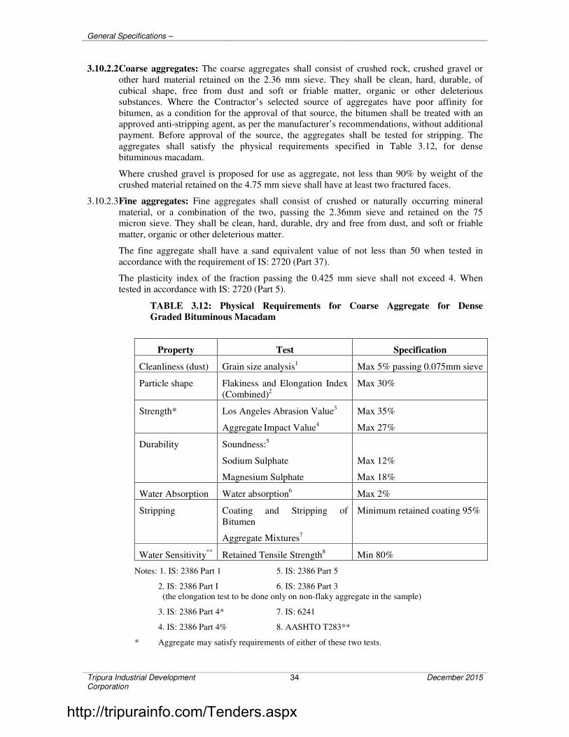
General Specifications –
Tripura Industrial Development Corporation
34 December 2015
3.10.2.2 Coarse aggregates: The coarse aggregates shall consist of crushed rock, crushed gravel or
other hard material retained on the 2.36 mm sieve. They shall be clean, hard, durable, of
cubical shape, free from dust and soft or friable matter, organic or other deleterious
substances. Where the Contractor’s selected source of aggregates have poor affinity for
bitumen, as a condition for the approval of that source, the bitumen shall be treated with an approved anti-stripping agent, as per the manufacturer’s recommendations, without additional
payment. Before approval of the source, the aggregates shall be tested for stripping. The
aggregates shall satisfy the physical requirements specified in Table 3.12, for dense
bituminous macadam.
Where crushed gravel is proposed for use as aggregate, not less than 90% by weight of the
crushed material retained on the 4.75 mm sieve shall have at least two fractured faces.
3.10.2.3 Fine aggregates: Fine aggregates shall consist of crushed or naturally occurring mineral
material, or a combination of the two, passing the 2.36mm sieve and retained on the 75 micron sieve. They shall be clean, hard, durable, dry and free from dust, and soft or friable
matter, organic or other deleterious matter.
The fine aggregate shall have a sand equivalent value of not less than 50 when tested in
accordance with the requirement of IS: 2720 (Part 37).
The plasticity index of the fraction passing the 0.425 mm sieve shall not exceed 4. When
tested in accordance with IS: 2720 (Part 5).
TABLE 3.12: Physical Requirements for Coarse Aggregate for Dense
Graded Bituminous Macadam
Property Test Specification
Cleanliness (dust) Grain size analysis1 Max 5% passing 0.075mm sieve
Particle shape Flakiness and Elongation Index
(Combined)2
Max 30%
Strength* Los Angeles Abrasion Value3
Aggregate Impact Value4
Max 35%
Max 27%
Durability Soundness:5
Sodium Sulphate
Magnesium Sulphate
Max 12%
Max 18%
Water Absorption Water absorption6 Max 2%
Stripping Coating and Stripping of
Bitumen
Aggregate Mixtures7
Minimum retained coating 95%
Water Sensitivity**
Retained Tensile Strength8 Min 80%
Notes: 1. IS: 2386 Part 1 5. IS: 2386 Part 5
2. IS: 2386 Part I 6. IS: 2386 Part 3
(the elongation test to be done only on non-flaky aggregate in the sample)
3. IS: 2386 Part 4* 7. IS: 6241
4. IS: 2386 Part 4% 8. AASHTO T283**
* Aggregate may satisfy requirements of either of these two tests.
http://tripurainfo.com/Tenders.aspx
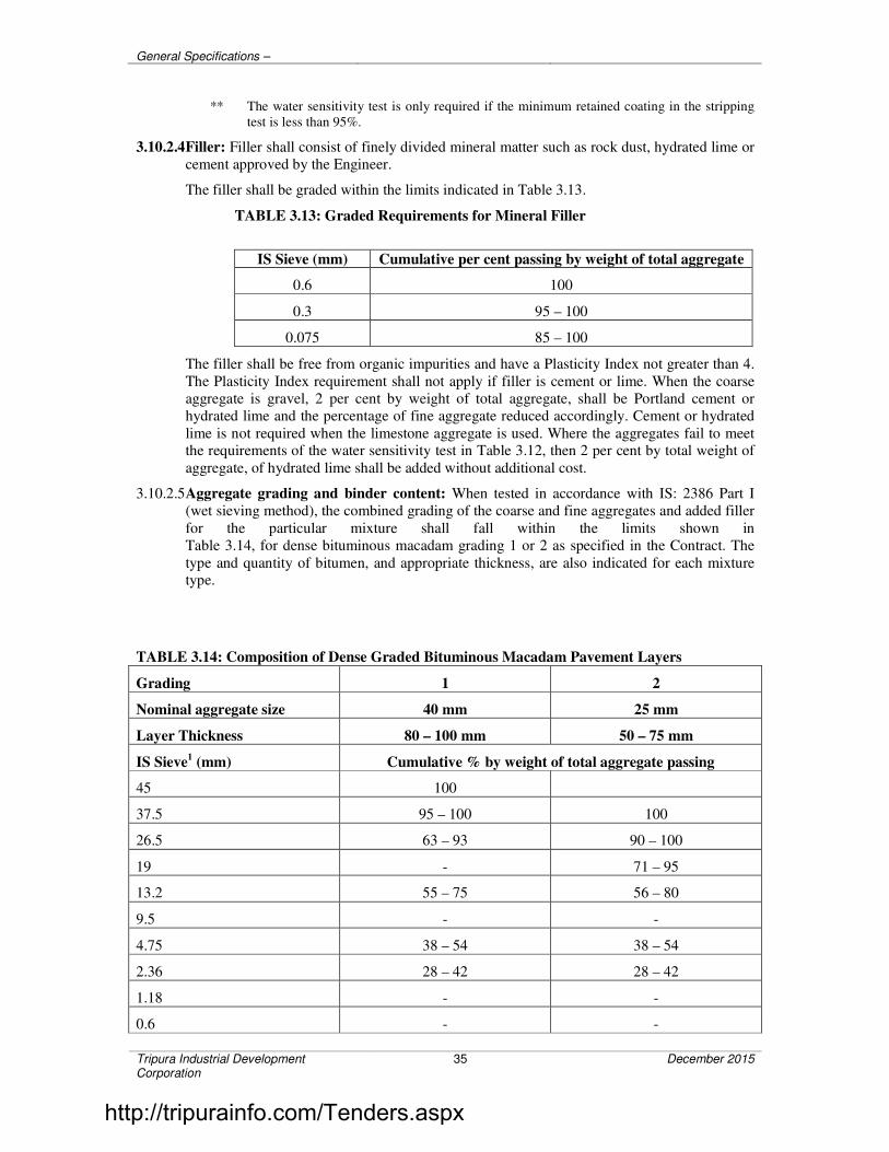
General Specifications –
Tripura Industrial Development Corporation
35 December 2015
** The water sensitivity test is only required if the minimum retained coating in the stripping
test is less than 95%.
3.10.2.4 Filler: Filler shall consist of finely divided mineral matter such as rock dust, hydrated lime or
cement approved by the Engineer.
The filler shall be graded within the limits indicated in Table 3.13.
TABLE 3.13: Graded Requirements for Mineral Filler
IS Sieve (mm) Cumulative per cent passing by weight of total aggregate
0.6 100
0.3 95 – 100
0.075 85 – 100
The filler shall be free from organic impurities and have a Plasticity Index not greater than 4.
The Plasticity Index requirement shall not apply if filler is cement or lime. When the coarse
aggregate is gravel, 2 per cent by weight of total aggregate, shall be Portland cement or
hydrated lime and the percentage of fine aggregate reduced accordingly. Cement or hydrated
lime is not required when the limestone aggregate is used. Where the aggregates fail to meet the requirements of the water sensitivity test in Table 3.12, then 2 per cent by total weight of
aggregate, of hydrated lime shall be added without additional cost.
3.10.2.5 Aggregate grading and binder content: When tested in accordance with IS: 2386 Part I
(wet sieving method), the combined grading of the coarse and fine aggregates and added filler
for the particular mixture shall fall within the limits shown in
Table 3.14, for dense bituminous macadam grading 1 or 2 as specified in the Contract. The
type and quantity of bitumen, and appropriate thickness, are also indicated for each mixture type.
TABLE 3.14: Composition of Dense Graded Bituminous Macadam Pavement Layers
Grading 1 2
Nominal aggregate size 40 mm 25 mm
Layer Thickness 80 – 100 mm 50 – 75 mm
IS Sieve1 (mm) Cumulative % by weight of total aggregate passing
45 100
37.5 95 – 100 100
26.5 63 – 93 90 – 100
19 - 71 – 95
13.2 55 – 75 56 – 80
9.5 - -
4.75 38 – 54 38 – 54
2.36 28 – 42 28 – 42
1.18 - -
0.6 - -
http://tripurainfo.com/Tenders.aspx

General Specifications –
Tripura Industrial Development Corporation
36 December 2015
0.3 7 – 21 7 – 21
0.15 - -
0.075 2 – 8 2 – 8
Bitumen content % by mass of
total mix2
Min 4.0 Min 4.5
Bitumen grade (pen) 65 or 90 65 or 90
Notes: 1. The combined aggregate grading shall not vary from the low limit on one sieve to the
high limit on the adjacent sieve.
2. Determined by the Marshall method.
3.10.3 Mixture Design
3.10.3.1 Requirement for the mixture: Apart from conformity with the grading and quality
requirements for individual ingredients, the mixture shall meet the requirements set out in
Table 3.15.
TABLE 3.15: Requirements for Dense Graded Bituminous Macadam
Minimum stability (kN at 60°C) 9.0
Minimum flow (mm) 2
Maximum flow (mm) 4
Compaction level (Number of blows) 75 blows on each of the two faces
of the specimen
Per cent air voids 3 – 6
Per cent voids in mineral aggregate (VMA) See Table 3.16 below
Per cent voids filled with bitumen (VFB) 65 -75
The requirements for minimum per cent voids in mineral aggregate (VMA) are set
out in Table 3.16.
TABLE 3.16: Minimum Per cent Voids in Mineral Aggregate (VMA)
Nominal Maximum
Particle Size 1
(mm)
Minimum VMA, Per cent Related to
Design Air Voids, Per cent2
3.0 4.0 5.0
9.5 14.0 15.0 16.0
12.5 13.0 14.0 15.0
19.0 12.0 13.0 14.0
25.0 11.0 12.0 13.0
37.5 10.0 11.0 12.0
Notes: 1. The nominal maximum particle size is one size larger than the first sieve to retain more than 10 per
cent.
2. Interpolate minimum voids in the mineral aggregate (VMA) for design air voids values between
those listed.
http://tripurainfo.com/Tenders.aspx

General Specifications –
Tripura Industrial Development Corporation
37 December 2015
3.10.3.2 Binder Content: The binder content shall be optimized to achieve the requirements of the
mixture set out in Table 3.15 and the traffic volume specified in the Contract. The Marshall
method for determining the optimum binder content shall be adopted as described in The
Asphalt Institute Manual MS-2, replacing the aggregates retained on the 26.5 mm sieve by the
aggregates passing the 26.5 mm sieve and retained on the 22.4 mm sieve, where approved by the Engineer.
Where 40 mm dense bituminous macadam mixture is specified, the modified Marshall
method described in MS-2 shall be used. This method requires modified equipment and
procedures; particularly the minimum stability values in Table 3.15 shall be multiplied by
2.25, and the minimum flow shall be 3 mm.
3.10.3.3 Job mix formula: The Contractor shall inform the Engineer in writing at least 20 days before
the start of the work, of the job mix formula proposed for use in the works, and shall give the
following details:
i) Source and location of all materials;
ii) Proportions of all materials expressed as follows where each is applicable:
a) Binder type, and percentage by weight of total mixture;
b) Coarse aggregate/Fine aggregate/Mineral filler as percentage by
weight of total aggregate including mineral filler;
iii) A single definite percentage passing each sieve for the mixed aggregate;
iv) The individual gradings of the individual aggregate fractions, and the
proportion of each in the combined grading.
v) The results of tests enumerated in Table 3.15 as obtained by the Contractor;
vi) Where the mixer is a batch mixer, the individual weights of each type of
aggregate, and binder per batch.
vii) Test results of physical characteristics of aggregates to be used;
viii) Mixing temperature and compacting temperature.
While establishing the job mix formula, the Contractor shall ensure that it is based on a
correct and truly representative sample of the materials that will actually be used in the work
and that the mixture and its different ingredients satisfy the physical and strength
requirements of these Specifications.
Approval of the job mix formula shall be based on independent testing by the Engineer for
which samples of all ingredients of the mix shall be furnished by the Contractor as required
by the Engineer.
The approved job mix formula shall remain effective unless and until a revised Job Mix
Formula is approved. Should a change in the source of materials be proposed, a new job mix
formula shall be forwarded to the Engineer for approval before the placing of the material.
3.10.3.4 Plant trials – permissible variation in job mix formula: Once the laboratory job mix
formula is approved, the Contractor shall carry out plant trials at the mixer to establish that
the plant can be set up to produce a uniform mix conforming to the approved job mix formula.
The permissible variations of the individual percentage of the various ingredients in the actual
mix from the job mix formula to be used shall be within the limits as specified in Table 3.17.
These variations are intended to apply to individual specimens taken for quality control tests
in accordance with Section 900.
TABLE 3.17: Permissible Variations form the Job Mix Formula
http://tripurainfo.com/Tenders.aspx
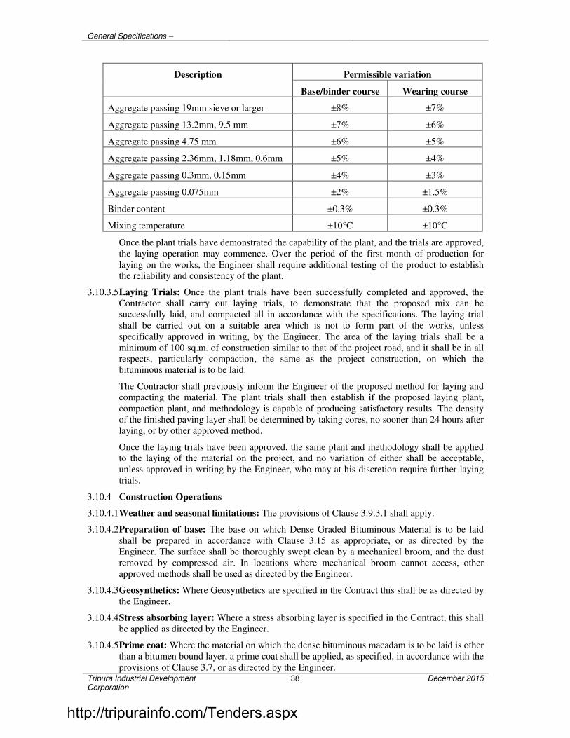
General Specifications –
Tripura Industrial Development Corporation
38 December 2015
Description Permissible variation
Base/binder course Wearing course
Aggregate passing 19mm sieve or larger ±8% ±7%
Aggregate passing 13.2mm, 9.5 mm ±7% ±6%
Aggregate passing 4.75 mm ±6% ±5%
Aggregate passing 2.36mm, 1.18mm, 0.6mm ±5% ±4%
Aggregate passing 0.3mm, 0.15mm ±4% ±3%
Aggregate passing 0.075mm ±2% ±1.5%
Binder content ±0.3% ±0.3%
Mixing temperature ±10°C ±10°C
Once the plant trials have demonstrated the capability of the plant, and the trials are approved,
the laying operation may commence. Over the period of the first month of production for
laying on the works, the Engineer shall require additional testing of the product to establish
the reliability and consistency of the plant.
3.10.3.5 Laying Trials: Once the plant trials have been successfully completed and approved, the
Contractor shall carry out laying trials, to demonstrate that the proposed mix can be
successfully laid, and compacted all in accordance with the specifications. The laying trial
shall be carried out on a suitable area which is not to form part of the works, unless
specifically approved in writing, by the Engineer. The area of the laying trials shall be a
minimum of 100 sq.m. of construction similar to that of the project road, and it shall be in all
respects, particularly compaction, the same as the project construction, on which the bituminous material is to be laid.
The Contractor shall previously inform the Engineer of the proposed method for laying and
compacting the material. The plant trials shall then establish if the proposed laying plant,
compaction plant, and methodology is capable of producing satisfactory results. The density
of the finished paving layer shall be determined by taking cores, no sooner than 24 hours after
laying, or by other approved method.
Once the laying trials have been approved, the same plant and methodology shall be applied
to the laying of the material on the project, and no variation of either shall be acceptable,
unless approved in writing by the Engineer, who may at his discretion require further laying
trials.
3.10.4 Construction Operations
3.10.4.1 Weather and seasonal limitations: The provisions of Clause 3.9.3.1 shall apply.
3.10.4.2 Preparation of base: The base on which Dense Graded Bituminous Material is to be laid
shall be prepared in accordance with Clause 3.15 as appropriate, or as directed by the
Engineer. The surface shall be thoroughly swept clean by a mechanical broom, and the dust
removed by compressed air. In locations where mechanical broom cannot access, other approved methods shall be used as directed by the Engineer.
3.10.4.3 Geosynthetics: Where Geosynthetics are specified in the Contract this shall be as directed by
the Engineer.
3.10.4.4 Stress absorbing layer: Where a stress absorbing layer is specified in the Contract, this shall
be applied as directed by the Engineer.
3.10.4.5 Prime coat: Where the material on which the dense bituminous macadam is to be laid is other
than a bitumen bound layer, a prime coat shall be applied, as specified, in accordance with the
provisions of Clause 3.7, or as directed by the Engineer.
http://tripurainfo.com/Tenders.aspx

General Specifications –
Tripura Industrial Development Corporation
39 December 2015
3.10.4.6 Tack coat: Where the material on which the dense bituminous macadam is to be placed is a
bitumen bound surface, a tack coat shall be applied as specified, in accordance with the
provisions of Clause 3.8 or as directed by the Engineer.
3.10.4.7 Mixing and transportation of the mixture: The provisions as specified in Clause 3.9.3.4
shall apply.
3.10.4.8 Spreading: The provisions of Clause 3.9.3.5 Shall apply
3.10.4.9 Rolling: The general provisions of Clause 3.9.3.6 shall apply, as modified by the approved
laying trails. The compaction process shall be carried out by the same plant, and using the
same method, as approved in the laying trials, which may be varied only with the express
approval of the Engineer in writing.
3.10.5 Opening to Traffic
The newly laid surface shall not be open to traffic for at least 24 hrs after laying and
completion of compaction, without the express approval of the Engineer in writing.
3.10.6 Surface Finish and Quality Control of Work
The surface finish of the completed construction shall conform to the requirements of Clause
3.15. All materials and workmanship shall comply with the provisions set out in Clause 3.15
of this Specification.
3.10.7 Arrangements for Traffic
During the period of construction, arrangements for traffic diversion shall be made in
accordance with the direction of the Engineer.
3.10.8 Measurement for Payment
Dense Graded Bituminous Materials shall be measured as finished work either in cubic
metres, tons or by the square metre at a specified thickness as detailed on the Contract
drawings, or documents, or as directed by the Engineer.
3.10.9 Rate
The contract unit rate for Dense Graded Bituminous Macadam shall be payment in full for
carrying out the all required operations as specified, and shall include, the provision of
bitumen, at 4.25 per cent by weight of the total mixture.
The variance in actual percentage of bitumen used will be assessed and the payment adjusted,
up or down, accordingly.
3.11 SEMI-DENSE BITUMINOUS CONCRETE
3.11.1 Scope
This clause specifies the construction of Semi Dense Bituminous Concrete, for use in
wearing/binder and profile corrective courses. This work shall consist of construction in a
single or multiple layers of semi dense bituminous concrete on a previously prepared
bituminous bound surface. A single layer shall be 25 mm to 100 mm in thickness.
3.11.2 Materials
3.11.2.1 Bitumen: The bitumen shall be paving bitumen of Penetration grade complying with Indian
Standard Specification for Paving Bitumen, IS: 73 and of the penetration indicated in Table
3.19, for semi dense bituminous concrete, or as otherwise specified in the Contract.
http://tripurainfo.com/Tenders.aspx

General Specifications –
Tripura Industrial Development Corporation
40 December 2015
3.11.2.2 Coarse aggregates: The coarse aggregates shall be generally as specified in Clause 3.10.2.2
except that the aggregates shall satisfy the physical requirements of Table 3.18.
3.11.2.3 Fine aggregates: The fine aggregates shall be all as specified in Clause 3.10.2.3.
3.11.2.4 Filler: Filler shall be generally as specified in Clause 3.10.2.4. Where the aggregates fail to
meet the requirements of the water sensitivity test in Table 3.18 then 2 per cent by total
weight of aggregate of hydrated lime shall be added without additional cost.
3.11.2.5 Aggregate grading and binder content: When tested in accordance with IS: 2386 Part I
(Wet sieving method), the combined grading of the coarse and fine aggregates and added
filler shall fall within the limits shown in Table 3.19 for gradings 1 or 2 as specified in the
Contract.
3.11.3 Mixture Design
3.11.3.1 Requirements for the mixture: Apart from conformity with the grading and quality
requirements of individual ingredients the mixture shall meet the requirements set out in
Table 3.20.
TABLE 3.18: Physical Requirements for Coarse Aggregate for Semi Dense
Bituminous Concrete Pavement Layers
Property Test Specification
Cleanliness (dust) Grain size analysis1 Max 5% passing 0.075mm sieve
Particle shape Flakiness and Elongation Index
(Combined)2
Max 30%
Strength* Los Angeles Abrasion Value3
Aggregate Impact Value
4
Max 35%
Max 27%
Polishing
Durability
Polished Stone Value5
Soundness:6
Sodium Sulphate
Magnesium Sulphate
Min 55
Max 12%
Max 18%
Water Absorption Water absorption7 Max 2%
Stripping Coating and Stripping of
Bitumen
Aggregate Mixtures9
Minimum retained coating 95%
Water Sensitivity** Retained Tensile Strength8 Min 80%
Notes: 1. IS: 2386 Part 1 6. IS: 2386 Part 5
2. IS: 2386 Part I 7. IS: 2386 Part 3
(the elongation test to be done only on non-flaky aggregate in the sample)
3. IS: 2386 Part 4* 8. AASHTO T283**
4. IS: 2386 Part 4% 9. IS: 6241
5. BS: 812 Part 114
* Aggregate may satisfy requirements of either of these two tests.
** The water sensitivity test is only required if the minimum retained coating in the stripping test is less than
95%.
http://tripurainfo.com/Tenders.aspx

General Specifications –
Tripura Industrial Development Corporation
41 December 2015
The requirements for minimum per cent voids in mineral aggregate (VMA) are set out in
Table 3.16.
3.11.3.2 Binder content: The binder content shall be optimized to achieve the requirements of the
mixture set out in Table 3.20 and the traffic volume as specified in the Contract. The Marshall
method for determining the optimum binder content shall be adopted as described in the
Asphalt Institute Manual MS-2, replacing the aggregates retained on the 26.5 mm sieve and retained on the 22.4 mm sieve, where approved by the Engineer.
TABLE 3.19: Composition of Semi Dense Bituminous Concrete Pavement Layers
Grading 1 2
Nominal aggregate size 13 mm 10 mm
Layer Thickness 35 – 40 mm 25 – 30 mm
IS Sieve1 (mm) Cumulative % by weight of total aggregate passing
45
37.5
26.5
19 100
13.2 90 – 100 100
9.5 70 - 90 90 - 100
4.75 35 – 51 35 – 51
2.36 24 – 39 24 – 39
1.18 15 - 30 15 - 30
0.6 - -
0.3 9 – 19 9 – 19
0.15 - -
0.075 3 – 8 3 – 8
Bitumen content % by mass of
total mix2
Min 4.5 Min 5.0
Bitumen grade (pen) 65* 65*
Notes: 1. The combined aggregate grading shall not vary from the low limit on one sieve to the high limit on
the adjacent sieve.
2. Determined by the Marshall method.
* Only in exceptional circumstances, 80/100 penetration grade my be used, as approved by the
Engineer.
TABLE 3.20: Requirements for Semi Dense Bituminous Pavement Layers
Minimum stability (kN at 60°C) 8.2
Minimum flow (mm) 2
Maximum flow (mm) 4
http://tripurainfo.com/Tenders.aspx
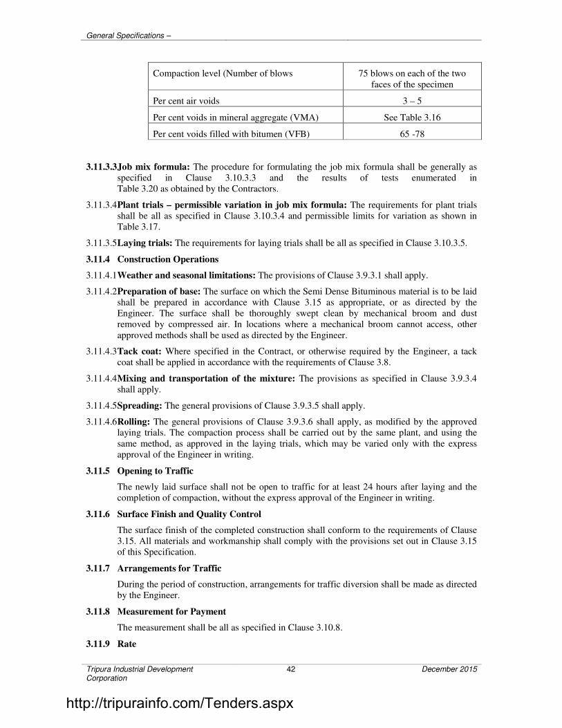
General Specifications –
Tripura Industrial Development Corporation
42 December 2015
Compaction level (Number of blows 75 blows on each of the two
faces of the specimen
Per cent air voids 3 – 5
Per cent voids in mineral aggregate (VMA) See Table 3.16
Per cent voids filled with bitumen (VFB) 65 -78
3.11.3.3 Job mix formula: The procedure for formulating the job mix formula shall be generally as
specified in Clause 3.10.3.3 and the results of tests enumerated in
Table 3.20 as obtained by the Contractors.
3.11.3.4 Plant trials – permissible variation in job mix formula: The requirements for plant trials
shall be all as specified in Clause 3.10.3.4 and permissible limits for variation as shown in
Table 3.17.
3.11.3.5 Laying trials: The requirements for laying trials shall be all as specified in Clause 3.10.3.5.
3.11.4 Construction Operations
3.11.4.1 Weather and seasonal limitations: The provisions of Clause 3.9.3.1 shall apply.
3.11.4.2 Preparation of base: The surface on which the Semi Dense Bituminous material is to be laid
shall be prepared in accordance with Clause 3.15 as appropriate, or as directed by the
Engineer. The surface shall be thoroughly swept clean by mechanical broom and dust
removed by compressed air. In locations where a mechanical broom cannot access, other
approved methods shall be used as directed by the Engineer.
3.11.4.3 Tack coat: Where specified in the Contract, or otherwise required by the Engineer, a tack
coat shall be applied in accordance with the requirements of Clause 3.8.
3.11.4.4 Mixing and transportation of the mixture: The provisions as specified in Clause 3.9.3.4
shall apply.
3.11.4.5 Spreading: The general provisions of Clause 3.9.3.5 shall apply.
3.11.4.6 Rolling: The general provisions of Clause 3.9.3.6 shall apply, as modified by the approved laying trials. The compaction process shall be carried out by the same plant, and using the
same method, as approved in the laying trials, which may be varied only with the express
approval of the Engineer in writing.
3.11.5 Opening to Traffic
The newly laid surface shall not be open to traffic for at least 24 hours after laying and the
completion of compaction, without the express approval of the Engineer in writing.
3.11.6 Surface Finish and Quality Control
The surface finish of the completed construction shall conform to the requirements of Clause
3.15. All materials and workmanship shall comply with the provisions set out in Clause 3.15
of this Specification.
3.11.7 Arrangements for Traffic
During the period of construction, arrangements for traffic diversion shall be made as directed
by the Engineer.
3.11.8 Measurement for Payment
The measurement shall be all as specified in Clause 3.10.8.
3.11.9 Rate
http://tripurainfo.com/Tenders.aspx

General Specifications –
Tripura Industrial Development Corporation
43 December 2015
The contract unit rate shall be all as specified in Clause 3.10.9, except that the rate shall
include the provision of bitumen at 4.75 per cent, by weight of total mixture. The variance in
actual percentage of bitumen used will be assessed and the payment adjusted up or down,
accordingly.
3.12 BITUMINOUS CONCRETE
3.12.1 Scope
This clause specifies the construction of Bituminous Concrete, for use in wearing and profile
corrective courses. This work shall consist of construction in a single or multiple layers of
bituminous concrete on a previously prepared bituminous bound surface. A single layers shall
be 25 mm to 100 mm in thickness.
3.12.2 Materials
3.12.2.1 Bitumen: The bitumen shall be paving bitumen of Penetration grade complying with Indian
Standard Specification for Paving Bitumen, IS: 73 and of the penetration indicated in Table
3.22, for bituminous concrete, or as otherwise specified in the Contract.
3.12.2.2 Coarse aggregates: The coarse aggregates shall be generally as specified in Clause 3.10.2.2 except that the aggregates shall satisfy the physical requirements of
Table 3.21.
3.12.2.3 Fine aggregates: The fine aggregates shall be all as specified in Clause 3.10.2.3.
3.12.2.4 Filler: Filler shall be generally as specified in Clause 3.10.2.4. Where the aggregates fail to
meet the requirements of the water sensitivity test in Table 3.21 then 2 per cent by total
weight of aggregate of hydrated lime shall be added without additional cost.
3.12.2.5 Aggregate grading and binder content: When tested in accordance with IS: 2386 Part I
(Wet grading method), the combined grading of the coarse and fine aggregates and added
filler shall fall within the limits shown in Table 3.22 for gradings 1 or 2 as specified in the
Contract.
3.12.3 Mixture Design
3.12.3.1 Requirements for the mixture: Apart from conformity with the grading and quality
requirements of individual ingredients the mixture shall meet the requirements set out in
Table 3.23.
The requirements for minimum per cent voids in mineral aggregate (VMA) are set out in
Table 3.16.
3.12.3.2 Binder content: The binder content shall be optimized to achieve the requirements of the mixture set out in Table 3.23 and the traffic volume as specified in the Contract. The Marshall
method for determining the optimum binder content shall be adopted as described in the
Asphalt Institute Manual MS-2, replacing the aggregates retained on the 26.5 mm sieve and
retained on the 22.4 mm sieve, where approved by the Engineer.
TABLE 3.21: Physical Requirements for Coarse Aggregate for Bituminous
Concrete Pavement Layers
Property Test Specification
Cleanliness (dust) Grain size analysis1 Max 5% passing 0.075mm sieve
Particle shape Flakiness and Elongation
Index (Combined)2
Max 30% (Combined)2
http://tripurainfo.com/Tenders.aspx
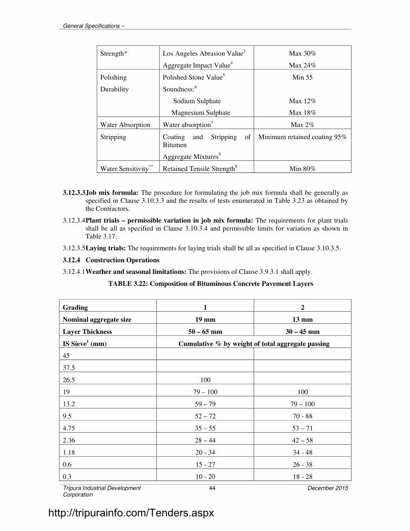
General Specifications –
Tripura Industrial Development Corporation
44 December 2015
Strength* Los Angeles Abrasion Value3
Aggregate Impact Value
4
Max 30%
Max 24%
Polishing
Durability
Polished Stone Value5
Soundness:6
Sodium Sulphate
Magnesium Sulphate
Min 55
Max 12%
Max 18%
Water Absorption Water absorption7 Max 2%
Stripping Coating and Stripping of
Bitumen
Aggregate Mixtures9
Minimum retained coating 95%
Water Sensitivity** Retained Tensile Strength8 Min 80%
3.12.3.3 Job mix formula: The procedure for formulating the job mix formula shall be generally as
specified in Clause 3.10.3.3 and the results of tests enumerated in Table 3.23 as obtained by
the Contractors.
3.12.3.4 Plant trials – permissible variation in job mix formula: The requirements for plant trials
shall be all as specified in Clause 3.10.3.4 and permissible limits for variation as shown in
Table 3.17.
3.12.3.5 Laying trials: The requirements for laying trials shall be all as specified in Clause 3.10.3.5.
3.12.4 Construction Operations
3.12.4.1 Weather and seasonal limitations: The provisions of Clause 3.9.3.1 shall apply.
TABLE 3.22: Composition of Bituminous Concrete Pavement Layers
Grading 1 2
Nominal aggregate size 19 mm 13 mm
Layer Thickness 50 – 65 mm 30 – 45 mm
IS Sieve1 (mm) Cumulative % by weight of total aggregate passing
45
37.5
26.5 100
19 79 – 100 100
13.2 59 – 79 79 – 100
9.5 52 – 72 70 - 88
4.75 35 – 55 53 – 71
2.36 28 – 44 42 – 58
1.18 20 - 34 34 - 48
0.6 15 - 27 26 - 38
0.3 10 - 20 18 - 28
http://tripurainfo.com/Tenders.aspx

General Specifications –
Tripura Industrial Development Corporation
45 December 2015
0.15 5 - 13 12-20
0.075 2 – 8 4 – 10
Bitumen content % by mass of
total mix2
5.0 – 6.0 5.0 – 7.0
Bitumen grade (pen) 65 65
Notes: 1. The combined aggregate grading shall not vary from the low limit on one sieve to the high limit on
the adjacent sieve.
2. Determined by the Marshall method.
TABLE 3.23: Requirements for Bituminous Pavement Layers
Minimum stability (kN at 60°C) 9.0
Minimum flow (mm) 2
Maximum flow (mm) 4
Compaction level (Number of blows 75 blows on each of the two faces
of the specimen
Per cent air voids 3 – 6
Per cent voids in mineral aggregate (VMA) See Table 3.16
Per cent voids filled with bitumen (VFB) 65 -75
Loss of stability on immersion in water at
60°C (ASTM D 1075)
Min. 75 per cent retained strength
3.12.4.2 Preparation of base: The surface on which the Bituminous concrete is to be laid shall be
prepared in accordance with Clause 3.15 as appropriate, or as directed by the Engineer. The
surface shall be thoroughly swept clean by mechanical broom and dust removed by compressed air. In locations where a mechanical broom cannot access, other approved
methods shall be used as directed by the Engineer.
3.12.4.3 Tack coat: Where specified in the Contract, or otherwise required by the Engineer, a tack
coat shall be applied in accordance with the requirements of Clause 3.8.
3.12.4.4 Mixing and transportation of the mixture: The provisions as specified in Clause 3.9.3.4
shall apply.
3.12.4.5 Spreading: The general provisions of Clause 3.9.3.5 shall apply.
3.12.4.6 Rolling: The general provisions of Clause 3.9.3.6 shall apply, as modified by the approved
laying trials.
3.12.5 Opening to Traffic
The newly laid surface shall not be open to traffic for at least 24 hours after laying and the
completion of compaction, without the express approval of the Engineer in writing.
3.12.6 Surface Finish and Quality Control
The surface finish of the completed construction shall conform to the requirements of Clause
3.15. All materials and workmanship shall comply with the provisions set out in Clause 3.15
of this Specification.
3.12.7 Arrangements for Traffic
http://tripurainfo.com/Tenders.aspx

General Specifications –
Tripura Industrial Development Corporation
46 December 2015
During the period of construction, arrangements for traffic diversion shall be made as directed
by the Engineer.
3.12.8 Measurement for Payment
The measurement shall be all as specified in Clause 3.10.8.
3.12.9 Rate
The contract unit rate shall be all as specified in Clause 3.10.9 except that the rate shall
include the provision of bitumen at 5.0 per cent, by weight of total mixture. The variance in
actual percentage of bitumen used will be assessed and the payment adjusted up or down,
accordingly.
3.13 TRAFFIC SIGNS
3.13.1 General
3.13.1.1 The colour, configuration, size and location of all traffic signs shall be in accordance with the
Code of Practice for Road Signs, IRC: 67 or as shown on the drawings.. In the absence of any
details or for any missing details, the signs shall be provided as directed by the Engineer.
3.13.1.2 The signs shall be either reflectorised or non-reflectorised as shown on the drawing or as
directed by the Engineer. When they are of reflectorised type, they shall be of retro-
reflectorised type and made of encapsulated lens type reflective sheeting vide Clause 3.13.3,
fixed over aluminium sheeting as per these Specifications.
3.13.1.3 In general, cautionary and mandatory signs shall be fabricated through process of screen
printing. In regard to informatory signs with inscriptions, either the message could be printed
over the reflective sheeting, or cut letters of non-reflective black sheeting used for the purpose
which must be bonded well on the base sheeting as directed by the Engineer.
3.13.2 Materials
The various materials and fabrication of the traffic signs shall conform to the following
requirements:
3.13.2.1 Concrete: Concrete shall be of the grade shown on the Contract drawings or otherwise as
directed by the Engineer.
3.13.2.2 Reinforcing steel: Reinforcing steel shall conform to the requirement of IS: 1786 unless
otherwise shown on the drawing.
3.13.2.3 Bolts, nuts, washers: High strength bolts shall conform to IS: 1367 whereas precision bolts,
nuts, etc., shall conform to IS: 1364.
3.13.2.4 Plates and supports: Plates and support sections for the sign posts shall conform to IS: 226
and IS: 2062 or any other relevant IS Specifications.
3.13.2.5 Aluminium: Aluminium sheets used for sign boards shall be of smooth, hard and corrosion
resistant aluminium alloy conforming to IS: 736-Material designation 24345 or 1900.
3.13.2.6 Signs with a maximum side dimension not exceeding 600 mm shall not be less than 1.5 mm
thick. All others shall be at least 2 mm thick. The thickness of the sheet shall be related to the
size of the sign and its support and shall be such that it does not bend or deform under the
prevailing wind and other loads.
3.13.2.7 In respect of sign sizes not covered by IRC: 67, the structural details (thickness, etc.) shall be
as per the approved drawings.
3.13.3 Traffic Signs Having Retro-reflective Sheeting
3.13.3.1 General requirements: The retro-reflective sheeting used on the sign shall consist of the
white or coloured sheeting having a smooth outer surface which has the property of retro-
reflection over its entire surface. It shall be weather-resistant and show colour fastness. It shall
http://tripurainfo.com/Tenders.aspx

General Specifications –
Tripura Industrial Development Corporation
47 December 2015
be new and unused and shall show no evidence of cracking, scaling, pitting, blistering, edge
lifting or curling and shall have negligible shrinkage or expansion. A certificate of having
tested the sheeting for these properties in an unprotected outdoor exposure facing the sun for
two years and its having passed these tests shall be obtained from a reputed laboratory, by the
manufacturer of the sheeting. The reflective sheeting shall be either of Engineering Grade material with enclosed lens or of High Intensity Grade with encapsulated lens. The type of the
sheeting to be used would depend upon the type, functional hierarchy and importance of the
road.
3.13.3.2 High intensity grade sheeting: This sheeting shall be of encapsulated lens type consisting of
spherical glass lens, elements adhered to a synthetic resin and encapsulated by a flexible,
transparent water-proof plastic having a smooth surface.
3.13.3.3 Engineering grade sheeting: This sheeting shall be of enclosed lens type consisting of
microscopic lens elements embedded beneath the surface of a smooth, flexible, transparent, water-proof plastic, resulting in a non-exposed lens optical reflecting system.
3.13.3.4 Messages/borders: The messages (legends, letters, numerals etc.) and borders shall either be
screen-printed or of cut-outs. Screen printing shall be processed and finished with materials
and in a manner specified by the sheeting manufacturer. Cut-outs shall be of materials as
specified by the sheeting manufacturer and shall be bonded with the sheeting in the manner
specified by the manufacturer.
3.13.3.5 Cut-out messages and borders, wherever used, shall be made out of retro-reflective sheeting
(as per Clause 3.,13.3.2 or 3.13.3.3 as applicable), except those in black which shall be of
non-reflective sheeting.
3.13.3.6 Colour: Unless otherwise specified, the general colour scheme shall be as stipulated in IS: 5
“Colour for Ready Mixed Paints”, viz.
Blue - IS Colour No. 166: French Blue
Red - IS Colour No. 537: Signal Red
Green - IS Colour No. 284: India Green
Orange - IS Colour No. 591: Deep Orange
The Colours shall be durable and uniform in acceptable hue when viewed in day light or
under normal headlights at night.
3.13.3.7 Adhesives: The sheeting shall either have a pressure-sensitive adhesive of the aggressive-tack
type requiring no heat, solvent or other preparation for adhesion to a smooth clean surface, or
a tack free adhesive activated by heat, applied in a heat-vacuum applicator, in a manner
recommended by the sheeting manufacturer. The adhesive shall be protected by an easily
removable liner (removable by peeling without soaking in water or other solvent) and shall be
suitable for the type of material of the base plate used for the sign. The adhesive shall form a
durable bond to smooth, corrosion and weather resistant surface of the base plate such that it
shall not be possible to remove the sheeting from the sign base in the piece by use of sharp instrument. In case of pressure-sensitive adhesive sheeting, the sheeting shall be applied in
accordance with the manufacturer’s Specifications. Sheeting with adhesives requiring use of
solvents or other preparation for adhesive shall be applied strictly in accordance with the
manufacturer’s instructions.
3.13.3.8 Refurbishment: Where existing signs are specified for refurbishment, the sheeting shall have
a semi-rigid aluminium backing pre-coated with aggressive-tack type pressure sensitive
adhesive. The adhesive shall be suitable for the type of material used for the sign and should
thoroughly bond with that material.
3.13.3.9 Fabrication:
http://tripurainfo.com/Tenders.aspx

General Specifications –
Tripura Industrial Development Corporation
48 December 2015
3.13.3.9.1 Surface to be reflectorised shall be effectively prepared to receive the retro-reflective
sheeting. The aluminium sheeting shall be de-greased either by acid or hot alkaline
etching and all scale/dust removed to obtain a smooth plain surface before the application
of retro-reflective sheeting. If the surface is rough, approved surface primer may be used.
After cleaning, metal shall not be handled, except by suitable device or clean canvas gloves, between all cleaning and preparation operation and application of reflective
sheeting/primer. There shall be no opportunity for metal to come in contact with grease,
oil or other contaminants prior to the application of retro-reflective sheeting.
3.13.3.9.2 Complete sheets of the material shall be used on the signs except where it is unavoidable;
at splices, sheeting with pressure sensitive adhesives shall be overlapped not less than 5
mm. Sheeting with heat-activated adhesives may be spliced with an overlap not less than
5 mm or butted with a gap not exceeding 0.75 mm. Where screen printing with
transparent colours is proposed, only butt jointing shall be used. The material shall cover
the sign surface evenly and shall be free from twists, cracks and folds. Cut-outs to
produce legends and borders shall be bonded with the sheeting in the manner specified by
the manufacturer.
3.13.3.10 Warranty and durability: The contractor shall obtain from the manufacturer a
seven-year warranty for satisfactory field performance including stipulated retro-reflectance
of the retro-reflective sheeting of high intensity grade and a five year warranty for the
adhesive sheeting of engineering grade and submit the same to the Engineer. In addition, a seven year and a five year warranty for satisfactory in-field performance of the finished sign
with retro-reflective sheeting of high intensity grade and engineering grade respectively,
inclusive of the screen printed or cut out letters/legends and their bonding to the retro-
reflective sheeting shall be obtained from the Contractor/supplier and passed on to the
Engineer. The Contractor/supplier shall also furnish a certification that the signs and materials
supplied against the assigned work meets all the stipulated requirements and carry the
stipulated warranty.
Processed and applied in accordance with recommended procedures, the reflective material
shall be weather resistant and, following cleaning, shall show no appreciable discolouration,
cracking, blistering or dimensional change and shall not have less than 50 per cent of the
specified minimum reflective intensity values when subjected to accelerated weathering for
1000 hours, using type E or EH Weatherometer (AASHTO Designation M 268).
3.13.4 Installation
3.13.4.1 Sign posts, their foundations and sign mountings shall be so constructed as to hold these in a
proper and permanent position against the normal storm wind loads or displacement by vandalism. Normally, signs with an area upto 0.9 sq.m shall be mounted on a single post, and
for greater area two or more supports shall be provided. Sign supports may be of mild steel,
reinforced concrete or galvanized iron (G.I). Post-end(s) shall be firmly fixed to the ground by
means of properly designed foundation. The work of foundation shall conform to relevant
Specifications as specified.
3.13.4.2 All Components of signs and supports, other than the reflective portion and G.I. posts shall be
thoroughly descaled, cleaned, primed and painted with two coats of epoxy paint. Any part of mild steel (M.S.) post below ground shall be painted with three coats of red lead paint.
3.13.4.3 The signs shall be fixed to the posts by welding in the case of steel posts and by bolts and
washers of suitable size in the case of reinforced concrete or G.I. posts. After the nuts have
been tightened, the tails of the bolts shall be furred over with a hammer to prevent removal.
3.13.5 Measurements for Payment
The measurement of standard cautionary, mandatory and information signs shall be in
numbers of different types of signs supplied and fixed, while for direction and place
identification signs, these shall be measured by area in square metres.
http://tripurainfo.com/Tenders.aspx

General Specifications –
Tripura Industrial Development Corporation
49 December 2015
3.13.6 Rate
The Contract unit rate shall be payment in full for the cost of making the road sign, including
all materials, installing it at the site and incidentals to complete the work in accordance with
the Specifications.
3.14 ROAD MARKINGS
3.14.1 General
The colour, width and layout of road markings shall be in accordance with the Code of Practice for Road Markings with paints, IRC: 35, and as specified in the drawings or as
directed by the Engineer.
3.14.2 Materials
Road markings shall be of hot applied thermoplastic compound, or reflectorised paint as
specified in the item and the material shall meet the requirements as specified below.
3.14.3 Hot Applied Thermoplastic Road Marking
3.14.3.1 General:
i) The work under this section consists of marking traffic stripes using a
thermoplastic compound meeting the requirements specified herein.
ii) The thermoplastic compound shall be screeded/extruded on to the pavement
surface in a molten state by suitable machine capable of controlled
preparation and laying with surface application of glass beads at a specific
rate. Upon cooling to ambient pavement temperature, it shall produce an
adherent pavement marking of specified thickness and width and capable of
resisting deformation by traffic.
iii) The colour of the compound shall be white or yellow (IS colour No. 356) as
specified in the drawings or as directed by the Engineer.
iv) Where the compound is to be applied to cement concrete pavement, a sealing
primer as recommended by the manufacturer, shall be applied to the
pavement in advance of placing of the stripes to ensure proper bonding of the
compound. On new concrete surface any laitance and/or curing compound
shall be removed before the markings are applied.
3.14.3.2 Thermoplastic Material
3.14.3.2.1 General: The thermoplastic material shall be homogeneously composed of aggregate,
pigment, resins and glass reflectorizing beads.
3.14.3.2.2 Requirements:
i) Composition: The pigment, beads, and aggregate shall be uniformly
dispersed in the resin. The material shall be free from all skins, dirt and
foreign objects and shall comply with requirements indicated in Table 3.24.
TABLE 3.24: Proportions of Constituents of Marking Material (Percentage by
weight)
Component White Yellow
http://tripurainfo.com/Tenders.aspx

General Specifications –
Tripura Industrial Development Corporation
50 December 2015
Binder 18.0 min. 18.0 min.
Glass Beads 30-40 30-40
Titanium Dioxide 10.0 min. -
Calcium Carbonate and
Inert Fillers
42.0 max.
See Note
Yellow Pigments -
Note: Amount of yellow pigment, calcium carbonate and inert fillers shall be at the option of
the manufacturer, provided all other requirements of this Specification are met.
ii) Properties: The properties of thermoplastic material, when tested in accordance with ASTM D36/BS-3262 (Part I), shall be as below:
a) Luminance:
White: Daylight luminance at 45 degrees-65 per cent min. as per
AASHTO M 249.
Yellow: Daylight luminance at 45 degrees 45 per cent min. as per
AASHTO M 249.
b) Drying time: When applied at a temperature specified by the
manufacturer and to the required thickness, the material shall set to
bear traffic in not more than 15 minutes.
c) Skid resistance: not less than 45 as per BS 6044.
d) Cracking resistance at low temperature: The material shall show no
cracks on application to concrete blocks.
e) Softening point: 102.5 ±9.5% C as per ASTM D 36.
f) Flow resistance: Not more than 25 per cent as per AASHTO M 249.
g) Yellowness index (for white thermoplastic paint): not more than 0.12
as per AASHTO M 249
iii) Storage life: The material shall meet the requirements of these Specifications
for a period of one year. The thermoplastic material must also melt uniformly
with no evidence of skins or unmelted particles for the one year storage period. Any material not meeting the above requirements shall be replaced by
the manufacturer/supplier/Contractor.
iv) Reflectorisation: Shall be achieved by incorporation of beads, the grading
and other properties of the beads shall be as specified in Clause 3.14.4.3.
v) Marking: Each container of the thermoplastic material shall be clearly and
indelibly marked with the following information:
1. The name, trade mark or other means of identification of
manufacturer
2. Batch number
3. Date of manufacture
4. Colour (white or yellow)
5. Maximum application temperature and maximum safe heating
temperature.
http://tripurainfo.com/Tenders.aspx

General Specifications –
Tripura Industrial Development Corporation
51 December 2015
vi) Sampling and testing: The thermoplastic material shall be sampled and
tested in accordance with the appropriate ASTM/BS method. The Contractor
shall furnish to the Employer a copy of certified test reports from the
manufacturers of the thermoplastic material showing results of all tests
specified herein and shall certify that the material meets all requirements of this Specification.
3.14.3.3 Reflectorising glass beads
3.14.3.3.1 General: This Specification covers two types of glass beads to be used for the production
of reflectorised pavement markings.
Type 1 beads are those which are a constituent of the basic thermoplastic compound
vide Table 3.24 and Type 2 beads are those which are to be sprayed on the surface
vide Clause 3.14.6.3.
3.14.3.3.2 The glass beads shall be transparent, colourless and free from milkiness, dark particles
and excessive air inclusions.
These shall conform to the requirements spelt out in Clause 3.14.4.3.3
3.14.3.3.3 Specific requirements
A. Gradation: The glass beads shall meet the gradation requirements for the
two types as given in Table 3.25.
TABLE 3.25: Gradation Requirements for Glass Beads
Sieve Size Per cent retained
Type 1 Type 2
1.18 mm 0 to 3 -
850 micron 5 to 20 0 to 5
600 micron - 5 to 20
425 micron 65 to 95 -
300 micron - 30 to 75
180 micron 0 to 10 10 to 30
Below 180 micron 0 0 to 15
B. Roundness: The glass beads shall have a minimum of 70 per cent true
spheres.
C. Refractive index: The glass beads shall have a minimum refractive index of
1.50.
D. Free flowing properties: The glass beads shall be free of hard lumps and
clusters and shall dispense readily under any conditions suitable for paint
striping. They shall pass the free flow-test.
3.14.3.3.4 Test methods: The specific requirements shall be tested with the following methods:
i) Free-flow test: Spread 100 grams of beads evenly in a 100 mm diameter glass
dish. Place the dish in a 250 mm inside diameter disiccator which is filled
within 25 mm of the top of a desiccator plate with sulphuric acid water
http://tripurainfo.com/Tenders.aspx

General Specifications –
Tripura Industrial Development Corporation
52 December 2015
solution (specific gravity 1.10). Cover the desiccator and let it stand for 4
hours at 20 to 29 degree C. Remove sample from desiccator, transfer beads to
a pan and inspect for lumps or clusters. Then pour beads into a clean, dry
glass funnel having a 100 mm stem and 6 mm orifice. If necessary, initiate
flow by lightly tapping the funnel. The glass spheres shall be essentially free of lumps and clusters and shall flow freely through the funnel.
ii) The requirements of gradation, roundness and refractive index of glass beads
and the amount of glass beads in the compound shall be tested as per BS
6088 and BS 3262 (Part I).
iii) The Contractor shall furnish to the Employer a copy of certified test reports
from the manufacturer of glass beads obtained from a reputed laboratory
showing results of all tests specified herein and shall certify that the material
meets all requirements of this Specification. However, if so required, these tests may be carried out as directed by the Engineer.
3.14.3.4 Application properties of thermoplastic material
3.14.3.4.1 The thermoplastic material shall readily get screeded/extruded at temperatures specified
by the manufacturers for respective method of application to produce a line of specified
thickness which shall be continuous and uniform in shape having clear and sharp edges.
3.14.3.4.2 The material upon heating to application temperatures, shall not exclude fumes, which are
toxic, obnoxious or injurious to persons or property.
3.14.3.5 Preparation:
i) The material shall be melted in accordance with the manufacturer’s
instructions in a heater fitted with a mechanical stirrer to give a smooth
consistency to the thermoplastic material to avoid local overheating. The
temperature of the mass shall be within the range specified by the
manufacturer, and shall on no account be allowed to exceed the maximum
temperature stated by the manufacturer. The molten material should be used
as expeditiously as possible and for thermoplastic material which has natural binders or is otherwise sensitive to prolonged heating, the material shall not
be maintained in a molten condition for more than 4 hours.
ii) After transfer to the laying equipment, the material shall be maintained within
the temperature range specified by the manufacturer for achieving the desired
consistency for laying.
3.14.3.6 Properties of finished road marking:
a) The stripe shall not be slippery when wet.
b) The marking shall not shift from the pavement in freezing weather.
c) After application and proper drying, the stripe shall show no appreciable
deformation or discolouration under traffic and under road temperatures upto 60°C.
d) The marking shall not deteriorate by contact with sodium chloride, calcium
chloride or oil drippings from traffic.
e) The stripe or marking shall maintain its original dimensions and position.
Cold ductility of the material shall be such as to permit normal movement
with the road surface without chopping or cracking.
http://tripurainfo.com/Tenders.aspx

General Specifications –
Tripura Industrial Development Corporation
53 December 2015
f) The colour of yellow marking shall conform to IS Colour No. 356 as given in
IS: 164.
3.14.4 Reflectorised Paint
Reflectorised paint, if used, shall conform to the Specification by the manufacturers and
approved by the Engineer. Reflectorising glass beads for reflectorising paints where used
shall conform to the requirement of Clause 3.14.4.3.
3.14.5 Application
3.14.5.1 Marking shall be done by machine. For locations where painting cannot be done by machine,
approved manual methods shall be used with prior approval of the Engineer. The Contractor
shall maintain control over traffic while painting operations are in progress so as to cause
minimum inconvenience to traffic compatible with protecting the workmen.
3.14.5.2 The thermoplastic material shall be applied hot either by screeding or extrusion process. After
transfer to the laying apparatus, the material shall be laid at a temperature within the range
specified by the manufacturer for the particular method of laying being used. The paint shall
be applied using a screed or extrusion machine.
3.14.5.3 The pavement temperature shall not be less than 10°C during application. All surfaces to be
marked shall be thoroughly cleaned of all dust, dirt, grease, oil and all other foreign matter
before application of the paint.
The material, when formed into traffic stripes, must be readily renewable by placing an
overlay of new material directly over an old line of compatible material. Such new material
shall so bond itself to the old line that no splitting or separation takes place.
Thermoplastic paint shall be applied in intermittent or continuous lines of uniform thickness
of at least 2.5 mm unless specified otherwise. Where arrows or letters are to be provided, thermoplastic compound may be hand-sprayed. In addition to the beads included in the
material, a further quantity of glass beads of Type 2, conforming to the above noted
Specification shall be sprayed uniformly into a mono-layer on to the hot paint line in quick
succession of the paint spraying operation. The glass beads shall be applied at the rate of 250
grams per square metre area.
3.14.5.4 The minimum thickness specified is exclusive of surface applied glass beads. The method of
thickness measurement shall be in accordance with Appendices B and C of BS – 3262 (Part 3).
3.14.5.5 The finished lines shall be free from ruggedness on sides and ends and be parallel to the
general alignment of the carriageway. The upper surface of the lines shall be level, uniform
and free from streaks.
3.14.6 Measurements for Payment
3.14.6.1 The painted markings shall be measured in sq.metres of actual area marked (excluding the
gaps, if any).
3.14.6.2 In respect of markings like directional arrows and lettering, etc., the measurement shall be by
numbers.
3.14.7 Rate
The Contract unit rate for road markings shall be payment in full compensation for furnishing
all labour, materials, tools, equipment, including all incidental costs necessary for carrying out
the work at the site conforming to these Specifications complete as per the approved
drawing(s) or as directed by the Engineer and all other incidental costs necessary to complete
the work to these Specifications.
3.15 QUALITY CONTROL TESTS DURING CONSTRUCTION
http://tripurainfo.com/Tenders.aspx

General Specifications –
Tripura Industrial Development Corporation
54 December 2015
3.15.1 General
The materials supplied and the works carried out by the Contractor shall conform to the
specifications prescribed in the following Clauses.
For ensuring the requisite quality of construction, the materials and works shall be subjected
to quality control tests, as described hereinafter. The testing frequencies set forth are the
desirable minimum and the Engineer shall have the full authority to carry out additional tests as frequently as he may deem necessary, to satisfy himself that the materials and works
comply with the appropriate specifications. However, the number of tests recommended in
Tables 3.27 and 3.28 may be reduced at the discretion of the Engineer if it is felt that
consistency in the quality of material can still be maintained with the reduced number of tests.
Test procedures for the various quality control tests are indicated in the respective Sections of
these Specifications or for certain tests within this Section. Where no specific testing
procedure is mentioned, the tests shall be carried out as per the prevalent accepted
engineering practice to the directions of the Engineer.
There shall not be any separate item in the Boq for the measures for quality control; the rates
for measurable items are deemed to include the cost of all the measures advised in the sub
clauses of 3.15
3.15.2 Surface Levels
The levels of the subgrade and different pavement courses as constructed, shall not vary from
those calculated with reference to the longitudinal and cross-profile of the rod shown on the
drawings or as directed by the Engineer beyond the tolerances mentioned in Table 3.26.
TABLE 3.26: Tolerances in Surface Levels
1. Subgrade + 20 mm
- 25 mm
2. Sub-base + 10 mm
a) Flexible pavement
b) Concrete pavement
[Dry lean concrete or Rolled concrete]
- 20 mm
+ 6 mm
- 10 mm
3. Base-course for flexible pavement
a) Bituminous course
b) Other-than bituminous
i) Machine laid
ii) Manually laid
+ 6 mmm
- 6 mm
+ 10 mm
- 10 mm
+ 15 mm
- 15 mm
4. Wearing course for flexible pavement
a) Machine laid
+ 6 mm
http://tripurainfo.com/Tenders.aspx

General Specifications –
Tripura Industrial Development Corporation
55 December 2015
b) Manually laid
- 6 mm
+ 10 mm
- 10 mm
5. Cement concrete pavement + 5 mm
- 6 mm*
* This may not exceed – 8 mm at 0 – 30 cm from the edges.
3.15.3 Tests on Earthwork for Embankment, Subgrade Construction and Cut Formation/Fill
Formation
3.15.3.1 Borrow material: Grid the borrow area at 25 m c/c (or closer, if the variability is high) to full
depth of proposed working. These pits should be logged and plotted for proper identification
of suitable sources of material. The following tests on representative samples shall be carried out:
a) Sand Content [IS: 2720 (Part-4)]: 2 tests per 3000 cubic metres of soil.
b) Plasticity Test [IS: 2720 (Part-5): Each type to be tested, 2 tests per 3000
cub.metres of soil.
c) Density Test [IS: 2720 (Part 8)]: Each soil type to be tested, 2 tests per 3000
cubic metres of soil.
d) Deleterious Content Test [IS: 2720 (Part 27)]: As and when required by the
Engineer.
e) Moisture Content Test [IS: 2720 (Part-2)]: One test for every 250 cubic metes
of soil.
f) CBR Test on materials to be incorporated in the subgrade on
soaked/unsoaked samples [IS: 2720 (part 16): one CBR test for every 3000
cu.m. atleast or closer as and when required by the Engineer.
3.15.3.2 Compaction Control: Control shall be exercised on each layer by taking at least one
measurement of density for each 1000 square metres of compacted area, or closer as required
to yield the minimum number of test results for evaluating a day’s work on statistical basis.
The determination of density shall be in accordance with IS: 2720 (Part-28). Test locations shall be chosen only through random sampling techniques. Control shall not be based on the
result of anyone test but on the mean value of a set of 5-10 density determinations. The
number of tests in one set of measurements shall be 6 (if non-destructive tests are carried out,
the number of tests shall be doubled) as long as it is felt that sufficient control over borrow
material and the method of compaction is being exercised. If considerable variations are
observed between individual density results, the minimum number of tests in one set of
measurement shall be increased to 10. The acceptance criteria shall be subject to the condition that the mean density is not less than the specified density plus:
( )deviationdardtansthetimes
Samplesof.No
65.165.1
5.0
−
However, for earthwork in shoulders and median (earthen) and in the subgrade, at least one
density measurement shall be taken for every 500 square metres for the compacted area
provided further that the number of tests in each set of measurements shall be atleast 10. In
other respects, the control shall be similar to the described earlier.
http://tripurainfo.com/Tenders.aspx

General Specifications –
Tripura Industrial Development Corporation
56 December 2015
3.15.3.3 Cut formation: Tests for he density requirements of cut formation shall be carried out in
accordance with Clause 3.15.3.2.
3.15.4 Tests on Sub-bases and Bases (excluding bitumen bound bases)
The tests and their frequencies for the different types of bases and sub-bases shall be as given
in Table 3.27. The evaluation of density results and acceptance criteria for compaction control
shall be on lines similar to those set out in Clause 3.15.3.2
3.15.4.1 Acceptance criteria: The acceptance criteria for tests on the strength of cement/lime
stabilized soil and distribution of stabilizer content shall be subject to the condition that the
mean value is not less than the specified value plus:
( )deviationdardtansthetimes
Samplesof.No
65.165.1
5.0
−
TABLE 3.27: Control Tests and Their Minimum Frequency for Sub-bases and Bases
(Excluding Bitumen Bound Bases)
Sl.
No.
Type of Construction Test Frequency (min.)
1. Granular i) Gradation
ii) Atterberg limits
iii) Moisture content prior to
compaction
iv) Density of compacted layer
v) Deleterious constituents
vi) C.B.R.
One test per 200 m3
One test per 200 m3
One test per 250 m3
One test per 500 m3
As required
As required
2. Wet Bound Macadam i) Aggregate impact Value
ii) Grading
iii) Flakiness and Elongation
Index
iv) Atterberg limits of portion
of aggregate passing 425
micron sieve
v) Density of compacted layer.
One test per 200 m3 of
aggregate
One test per 100 m3 of aggregate
One test per 200 m3 of
aggregate
One test per 100 m3 of
aggregate
One test per 500 m3
3.15.5 Tests on Bituminous Construction
3.15.5.1 Tests and frequency: The tests and their minimum frequencies for the different types of
bituminous works shall be as given in Table 3.28. The Engineer may direct additional testing
as required.
3.15.5.2 Acceptance criteria: The acceptance criteria for tests on density and Marshall stability shall
be subject to the condition that the mean value is not less than the specified value plus:
( )deviationdardtansthetimes
Samplesof.No
65.165.1
5.0
−
http://tripurainfo.com/Tenders.aspx

General Specifications –
Tripura Industrial Development Corporation
57 December 2015
TABLE 3.28: Control Tests for Bituminous works, and their Minimum Frequency
Sl.
No.
Type of Construction Test Frequency (min.)
1. Prime Coat/Tack
Coat/Fog Spray
i) Quality of binder
ii) Binder temperature for
application
iii) Rate of spread of Binder
Number of samples per lot and
tests as per IS: 73, IS: 217 and
IS: 8887 as applicable.
At regular close intervals.
One test per 500m2 and not less
than two tests per day.
2. Bituminous Macadam i) Quality of binder
ii) Aggregate Impact Value/Los
Angeles Abrasion Value
iii) Flakiness Index and
Elongation Index
iv) Stripping Value
v) Water sensitivity of mix
vi) Grading of aggregates
vii) Water absorption of
aggregates
viii) Soundness (Magnesium
and Sodium Sulphate)
ix) Percentage of fractured
Number of samples per lot and
tests as per IS: 73, IS: 217 and
IS: 8887 as applicable.
One test per 50 m3 of aggregate
One test per 50 m3 of aggregate
Initially one set of 3
representative specimens for each source of supply.
Subsequently when warranted
by changes in the quality of
aggregates
Initially one set of 3
representative specimens for
each source of supply. Subsequently when warranted
by changes in the quality of
aggregates
Two tests per day per plant
both on the individual
constituents and mixed
aggregates form the dryer
Initially one set of 3 representative specimens for
each source of supply.
Subsequently when warranted
by changes in the quality of
aggregates
Initially, one determination by
each method for each source of supply, then as warranted by
change in the quality of the
aggregates.
When gravel is used, one test
per 50m3 of aggregate
Periodic, subject to minimum
http://tripurainfo.com/Tenders.aspx

General Specifications –
Tripura Industrial Development Corporation
58 December 2015
faces
x) Binder content and aggregate
grading
xi) Control of temperature of binder and aggregate for mixing
and of the mix at the time of
laying and rolling
xii) Rate of spread of mixed
material
xiii) Density of Compacted
layer
to two tests per day per plant
At regular close intervals
Regular control through checks
of layer thickness
One test per 250m2 of area
3. Dense Bituminous
Macadam/Semi Dense
Bituminous
Concrete/Bituminous
Concrete
i) Quality of binder
ii) Aggregate Impact Value/Los
Angeles Abrasion Value
iii) Flakiness Index and
Elongation Index
iv) Stripping Value
v) Soundness (Magnesium and
Sodium Sulphate)
vi) Water absorption of
aggregates
vii) Sand equivalent test
viii) Plasticity Index
ix) Polished stone value
x) Percentage of fractured faces
xi) Mix grading
Number of samples per lot and
tests as per IS: 73, IS: 217 and
IS: 8887 as applicable.
One test per 50 m3 of aggregate
One test per 50 m3 of aggregate
Initially one set of 3
representative specimens for each source of supply.
Subsequently when warranted
by changes in the quality of
aggregates
Initially one set of 3
representative specimens for
each source of supply. Subsequently when warranted
by changes in the quality of
aggregates
Initially one set of 3
representative specimens for
each source of supply.
Subsequently when warranted by changes in the quality of
aggregates
As required
As required
As required, for Semi Dense
Bituminous
Concrete/Bituminous Concrete
When gravel is used, one test
per 50m3 of aggregate
One set of tests on individual constituents and mixed
aggregate from the dryer for
each 400 tonnes of mix subject
http://tripurainfo.com/Tenders.aspx

General Specifications –
Tripura Industrial Development Corporation
59 December 2015
to a minimum of two tests per
plant per day
3.15.6 Measurement for payment
There shall not be a separate item in the Bill of Quantities, for the measures for quality
control; the rates for measurable items in the Contract are deemed to include the cost of all the
tests advised at specified frequencies, in the sub clauses of Clause 3.15
http://tripurainfo.com/Tenders.aspx

TRIPURA INDUSTRIAL DEVELOPMENT CORPORATION
Tender for Setting up of Land Custom Station Muhurighat,Belonia,
TIDC/LCS/CIVIL/MUHURIGHAT/01/2018
Project Management Consultants:
TRIPURA INDUSTRIAL DEVELOPMENT CORPORATION
Tender for Setting up of Land Custom Station Muhurighat,Belonia,
Tripura
TIDC/LCS/CIVIL/MUHURIGHAT/01/2018-19
BOOK – 3
Bill of Quantities
Consultants: - July
TRIPURA INDUSTRIAL DEVELOPMENT CORPORATION
Tender for Setting up of Land Custom Station Muhurighat,Belonia,
19
July 2018
http://tripurainfo.com/Tenders.aspx

SL NO DESCRIPTION AMOUNT REMARKS
1 Civil, Interior, Plumbing and Sanitary Works Rs. 47,829,947
2 Internal Roads & Cross Drainage works Rs. 20,310,297
3 Compound Wall Estimate Rs. 5,168,002
4 Watersupply works Rs. 6,531,890
5 Site Development Rs. 2,725,050
6 Ware house with Toilet Block Rs. 21,795,570
7 Plant and Mechinery Rs. 3,000,000
8 Electrical Rs. 6,717,583
GRAND TOTAL = Rs. 114,078,339
COST SUMMARY
LCS MUHURIGHAT AT BELONIA
http://tripurainfo.com/Tenders.aspx
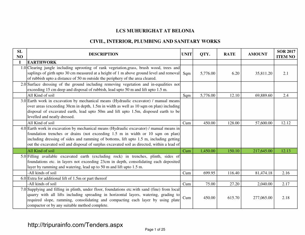
SL
NODESCRIPTION UNIT QTY. RATE AMOUNT
SOR 2017
ITEM NO
I EARTHWORK
1.0 Clearing jungle including uprooting of rank vegetation,grass, brush wood, trees and
saplings of girth upto 30 cm measured at a height of 1 m above ground level and removal
of rubbish upto a distance of 50 m outside the periphery of the area cleared.
Sqm 5,776.00 6.20 35,811.20 2.1
2.0 Surface dressing of the ground including removing vegetation and in-equalities not
exceeding 15 cm deep and disposal of rubbish, lead upto 50 m and lift upto 1.5 m.
All Kind of soil Sqm 5,776.00 12.10 69,889.60 2.4
3.0 Earth work in excavation by mechanical means (Hydraulic excavator) / manual means
over areas (exceeding 30cm in depth, 1.5m in width as well as 10 sqm on plan) including
disposal of excavated earth, lead upto 50m and lift upto 1.5m, disposed earth to be
CIVIL, INTERIOR, PLUMBING AND SANITARY WORKS
LCS MUHURIGHAT AT BELONIA
disposal of excavated earth, lead upto 50m and lift upto 1.5m, disposed earth to be
levelled and neatly dressed.
All Kind of soil Cum 450.00 128.00 57,600.00 12.12
4.0 Earth work in excavation by mechanical means (Hydraulic excavator) / manual means in
foundation trenches or drains (not exceeding 1.5 m in width or 10 sqm on plan)
including dressing of sides and ramming of bottoms, lift upto 1.5 m, including getting
out the excavated soil and disposal of surplus excavated soil as directed, within a lead of
50 m.All Kind of soil Cum 1,450.00 150.10 217,645.00 12.13
5.0 Filling available excavated earth (excluding rock) in trenches, plinth, sides of
foundations etc. in layers not exceeding 23cm in depth, consolidating each deposited
layer by ramming and watering, lead up to 50 m and lift upto 1.5 m.
-All kinds of soil Cum 699.95 116.40 81,474.18 2.16
6.0 Extra for additional lift of 1.5m or part thereof
-All kinds of soil Cum 75.00 27.20 2,040.00 2.17
7.0 Supplying and filling in plinth, under floor, foundations etc.with sand (fine) from local
quarry with all lifts including spreading in horizontal layers, watering, grading to
required slope, ramming, consolidating and compacting each layer by using plate
compactor or by any suitable method complete.
Cum 450.00 615.70 277,065.00 2.18
Page 1 of 25http://tripurainfo.com/Tenders.aspx

SL
NODESCRIPTION UNIT QTY. RATE AMOUNT
SOR 2017
ITEM NO
8.0 Supplying chemical emulsion in sealed containers including delivery as specified. 2.19
Chlorpyriphos/Lindane emulsifiable concentrate of 20% Ltrs 150.00 287.60 43,140.00 2.19.1
Treatment of soil under plinth filling using chemical emulsion @ 1 litre per hole 300 mm
apart including drilling 12mm dia holes and plugging with sand filling.2.20.3
With Chlorpyriphos/Lindane E.C. 20% with 1% concentration. Sqm 365.00 48.80 17,812.00 2.20.3.1
9.0 Providing and laying dry brick on edge flooring in required pattern complete. Sqm 850.00 628.10 533,885.00 10.4
II PLAIN CEMENT CONCRETE WORK.
1 Providing and laying in position cement concrete of specified grade excluding the cost of
centring and shuttering -4.1
-All work upto plinth level:
a) 1:3:6 ( 1 Cement: 3 fine sand : 6 graded stone aggregate 20 mm nominal size) Cum 225.65 7,567.60 1,707,628.94 4.1.5
2 Providing and laying damp-proof course with cement concrete 1:2:4 (1 cement: 2 coarse
sand : 4 graded stone aggregate 12.5mm/20mm nominal size). 4.5.1
a) D.P.C 50mm thick Sqm 178.00 460.40 81,951.20 4.5.1.2
3 Centering shuttering including struttings, propping etc. and removal of form work for:4.3
a) Foundations, footings, bases for columns etc. for mass concrete with steel formwork. Sqm285.00 234.30 66,775.50 4.3.1
Page 2 of 25http://tripurainfo.com/Tenders.aspx
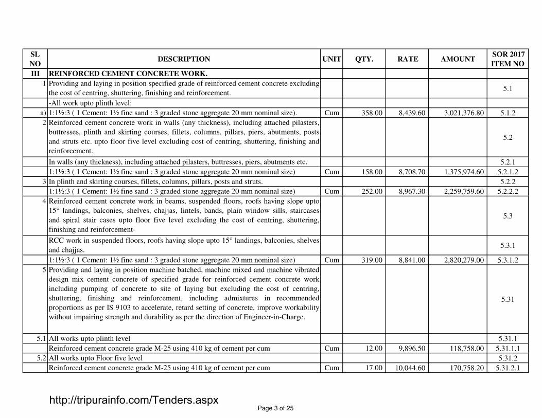
SL
NODESCRIPTION UNIT QTY. RATE AMOUNT
SOR 2017
ITEM NO
III REINFORCED CEMENT CONCRETE WORK.
1 Providing and laying in position specified grade of reinforced cement concrete excluding
the cost of centring, shuttering, finishing and reinforcement.5.1
-All work upto plinth level:
a) 1:1½:3 ( 1 Cement: 1½ fine sand : 3 graded stone aggregate 20 mm nominal size). Cum 358.00 8,439.60 3,021,376.80 5.1.2
2 Reinforced cement concrete work in walls (any thickness), including attached pilasters,
buttresses, plinth and skirting courses, fillets, columns, pillars, piers, abutments, posts
and struts etc. upto floor five level excluding cost of centring, shuttering, finishing and
reinforcement.
5.2
In walls (any thickness), including attached pilasters, buttresses, piers, abutments etc. 5.2.1
1:1½:3 ( 1 Cement: 1½ fine sand : 3 graded stone aggregate 20 mm nominal size) Cum 158.00 8,708.70 1,375,974.60 5.2.1.2
3 In plinth and skirting courses, fillets, columns, pillars, posts and struts. 5.2.2
1:1½:3 ( 1 Cement: 1½ fine sand : 3 graded stone aggregate 20 mm nominal size) Cum 252.00 8,967.30 2,259,759.60 5.2.2.2
4 Reinforced cement concrete work in beams, suspended floors, roofs having slope upto
15° landings, balconies, shelves, chajjas, lintels, bands, plain window sills, staircases
and spiral stair cases upto floor five level excluding the cost of centring, shuttering,
finishing and reinforcement-
5.3
RCC work in suspended floors, roofs having slope upto 15° landings, balconies, shelves
and chajjas.5.3.1
1:1½:3 ( 1 Cement: 1½ fine sand : 3 graded stone aggregate 20 mm nominal size) Cum 319.00 8,841.00 2,820,279.00 5.3.1.2
5 Providing and laying in position machine batched, machine mixed and machine vibrated
design mix cement concrete of specified grade for reinforced cement concrete work
including pumping of concrete to site of laying but excluding the cost of centring,
shuttering, finishing and reinforcement, including admixtures in recommended
proportions as per IS 9103 to accelerate, retard setting of concrete, improve workability
without impairing strength and durability as per the direction of Engineer-in-Charge.
5.31
5.1 All works upto plinth level 5.31.1
Reinforced cement concrete grade M-25 using 410 kg of cement per cum Cum 12.00 9,896.50 118,758.00 5.31.1.1
5.2 All works upto Floor five level 5.31.2
Reinforced cement concrete grade M-25 using 410 kg of cement per cum Cum 17.00 10,044.60 170,758.20 5.31.2.1
Page 3 of 25http://tripurainfo.com/Tenders.aspx

SL
NODESCRIPTION UNIT QTY. RATE AMOUNT
SOR 2017
ITEM NO
6 Centering shuttering including struttings, propping etc. and removal of form work for:5.9
a) Foundations, footings, bases for columns etc. for mass concrete with Timber Plank Sqm 465.00 226.10 105,136.50 5.9.1.1
b) Walls (any thickness), including attached pilasters, buttresses, plinth and string courses
etc. using shuttering plySqm 375.00 327.80 122,925.00 5.9.3
c) Suspended floors, roofs, landings, balconies and access platform with 12 mm thick
shuttering ply.Sqm 1,648.00 452.10 745,060.80 5.9.4.2
d) Lintels, beams, plinth beams, girders, bressumers and cantilevers with shuttering ply. Sqm 2,350.00 327.70 770,095.00 5.9.5.1
e) Columns, Pillars, Piers, Abutments, Posts and Struts with shuttering ply. Sqm 1,473.00 429.30 632,358.90 5.9.6.1
5 Reinforcement for R.C.C. work including straightening, cutting, bending, placing in
position and binding all complete upto floor five level.5.20
a) Thermo-Mechanically Treated bars/ Cold twisted deformed steel bars. Kg 76,844.00 59.70 4,587,586.80 5.20.4
Page 4 of 25http://tripurainfo.com/Tenders.aspx
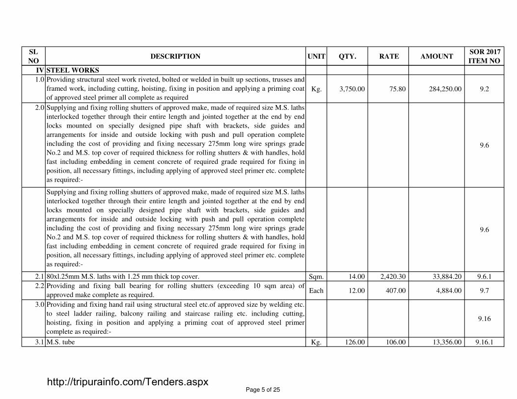
SL
NODESCRIPTION UNIT QTY. RATE AMOUNT
SOR 2017
ITEM NO
IV STEEL WORKS
1.0 Providing structural steel work riveted, bolted or welded in built up sections, trusses and
framed work, including cutting, hoisting, fixing in position and applying a priming coat
of approved steel primer all complete as required
Kg. 3,750.00 75.80 284,250.00 9.2
2.0 Supplying and fixing rolling shutters of approved make, made of required size M.S. laths
interlocked together through their entire length and jointed together at the end by end
locks mounted on specially designed pipe shaft with brackets, side guides and
arrangements for inside and outside locking with push and pull operation complete
including the cost of providing and fixing necessary 275mm long wire springs grade
No.2 and M.S. top cover of required thickness for rolling shutters & with handles, hold
fast including embedding in cement concrete of required grade required for fixing in
position, all necessary fittings, including applying of approved steel primer etc. complete
as required:-
9.6
Supplying and fixing rolling shutters of approved make, made of required size M.S. laths
interlocked together through their entire length and jointed together at the end by end
locks mounted on specially designed pipe shaft with brackets, side guides and
arrangements for inside and outside locking with push and pull operation complete
including the cost of providing and fixing necessary 275mm long wire springs grade
No.2 and M.S. top cover of required thickness for rolling shutters & with handles, hold
fast including embedding in cement concrete of required grade required for fixing in
position, all necessary fittings, including applying of approved steel primer etc. complete
as required:-
9.6
2.1 80xl.25mm M.S. laths with 1.25 mm thick top cover. Sqm. 14.00 2,420.30 33,884.20 9.6.1
2.2 Providing and fixing ball bearing for rolling shutters (exceeding 10 sqm area) of
approved make complete as required.Each 12.00 407.00 4,884.00 9.7
3.0 Providing and fixing hand rail using structural steel etc.of approved size by welding etc.
to steel ladder railing, balcony railing and staircase railing etc. including cutting,
hoisting, fixing in position and applying a priming coat of approved steel primer
complete as required:-
9.16
3.1 M.S. tube Kg. 126.00 106.00 13,356.00 9.16.1
Page 5 of 25http://tripurainfo.com/Tenders.aspx

SL
NODESCRIPTION UNIT QTY. RATE AMOUNT
SOR 2017
ITEM NO
3.2 E.R.W. tubes. Kg. 93.00 120.90 11,243.70 9.16.2
3.4 G.I.pipes. Kg. 70.00 115.70 8,099.00 9.16.3
4.0 Providing and fixing M.S. round holding down bolts with nuts and wahser plates
complete as per standard design.Kg. 75.00 76.30 5,722.50 9.17
V STRUCTURAL STEEL WORK
1.0 Providing and painting all steelwork with (i) one primer coat of inorganic zinc silicate
(min. Vs 62%) 50 micron (ii) one coat of epoxy HB MIO brown (min Vs 55%) 75
micron (iii) one coat of polyurethane paint (min. Vs. 40%) 40 microns including all
material,one coat of epoxy HB paint (min. Vs 60%) 100 microns (iv) labour, scaffolding
etc. The surface shall be shot blast to SA 2.5 standard using grit. The paint shall be
applied as manufacturer's specifications and the item shall include necessary testing, test
certificate etc.
a) One coat of inorganic zinc silicate, 50 microns & One coat of polyurethane paint, 40MT 18.34 25,000.00 458,575.00
microns.MT 18.34 25,000.00 458,575.00
2.0 Providing hot dip galvanizing to steel work, insert plates, insert angles, hold fasts, etc as
specified as per IS 4759 for a thickness of 100 microns.Mt 0.49 25,000.00 12,175.00
3.0 Providing, fabricating & fixing in position stainless steel work of grade SS 316 for any
structural members, insert plates, bolts, nuts, washers, signages, railings including
specified finishes etc.
Kg 250.00 700.00 175,000.00
4.0 Providing and Shear Studs 19mm X 95 mm 3/4 S3L 53/16 (Nelson Brand) Nos 50.00 82.00 4,100.00
(Panchsheel Fasteners Pvt. Ltd, 5008, Bazara Sirkiwalan,Haus Qazi, New Delhi -
110006 T - 011 23218332)
5.0 Providing and fixing TR60 X 0.9mm S350 Grade metal deck for composite floor. Sqm 48.00 901.00 43,248.00
6.0 Providing and fixing short length G.I. grating all complete. (for Cafeteria Kitchen) Sqm 14.00 400.00 5,600.00
Page 6 of 25http://tripurainfo.com/Tenders.aspx

SL
NODESCRIPTION UNIT QTY. RATE AMOUNT
SOR 2017
ITEM NO
VI WATERPROOFING
RCC Retaining wall
1.0 Retaining wall waterproofing to be carried out as per the procedure/ specifications of
M/s. Nina Concrete Systems Pvt. Ltd. Sqm 450.00 1,500.00 675,000.00
Providing & mixing fiber mesh stealth e3 multi dimensional 100% virgin polypropylene
fibers in the concrete of the retaining wall @ 0.45 kg/cum of concrete, stealth e3 fibers
shall be added to the concrete during the mixing process either by batching plant or
mixer alternatively stealth e3 fibers can be added directly into the transit mixer at site,
immediately prior to placing the concrete.
Providing & applying AH hydrocap crystallization based waterproofing system of M/s
Anti hydro International Inc. USA over the PCC as a slurry application in 2 coats at the
dosage arte of 1 kg/sqm on the external surface of the retaining wall, curing for 3 days
etc complete. incl grouting construction joints using waterproof slurry cement with
cebex 100 @ 225 gms /bag of cement .cebex 100 @ 225 gms /bag of cement .
Providing & applying 25mm thick water proof protective screed to retaining wall
admixed with proof sol integral water proofing compound @ 2% by weight of cement &
e3 stealth fibers @ 80 gms/bag of cement .The top surface when still green shall be
covered with a slurry of cement , proof sol & water trowelled to smooth finish.
VII BRICK WORK
Note:
Manual mixing of cement mortars have been considered here. However, for using of
mechanical mixer, the cost will differ with manual mixing as referred to SH:3/Mortar.
Sand can be either coarse or fine as required/available. Here, provision of fine sand is
considered only due to non-availability of coarse sand in Tripura. However, if design
dictates for use of coarse sand, then seperate analysis may be made as per site condition.
Bricks shall be soaked in water before use for a period for the water to just penetrate the
whole depth of the bricks. Alternatively bricks may be adequately soaked in stacks by
profusely spraying with clean water at regular intervals for a period not less than six
hours. When the bricks are soaked they shall be removed from the tank sufficiently early
so that at the time of laying they are skin-dry. Such soaked bricks shall be stacked on a
clean place where they are not again spoiled by dirt earth etc.
Page 7 of 25http://tripurainfo.com/Tenders.aspx

SL
NODESCRIPTION UNIT QTY. RATE AMOUNT
SOR 2017
ITEM NO
Green work shall be protected from the effects of sun and rain by suitable covering and
also from damage, mortar dropping etc.during the execution of the work. Masonry work
in cement or composite mortar shall be kept constantly moist on all faces for a minimum
period of seven days. In case of masonry with fat lime mortar, curing shall commence
two days after laying of masonry and shall continue for at least seven days thereafter.
For earth quake resistance brick masonry work as specified in IS:4326-1993, the
essential elements required to be constructed are : (i) RCC band of approved grade of
concrete and steel at Plinth level, Sill level, Lintel level, Floor / Roof level (ii) Vertical
reinforcement of approved grade & dia. at the corners and junctions of all rooms, side/
jamb of openings (doors, windows etc.)
Consumption of bricks has been considered as per the sizes of the bricks available in
Tripura.
Locally available well burnt 1st class bricks and 2nd class bricks with following Locally available well burnt 1st class bricks and 2nd class bricks with following
classification & dimension will be used:-
All other specification for quality, sampling and tests including efflorescence of bricks
shall generally be as Chapter - 6 of CPWD's specification.
1.0 First class brick work in foundation and plinth including cost of all materials as required
complete:-6.1
1.1 In cement mortar 1:5 ( 1 cement : 5 fine sand ). Cum. 75.00 5,278.50 395,887.50 6.1.4
2.0 Second class brick work in foundation and plinth including cost of all materials as
required complete:-6.2
2.1 In cement mortar 1:5 ( 1 cement : 5 fine sand ). Cum. 3.50 4,670.70 16,347.45 6.2.4
Dimension ( in mm) {Length x Breadth x Depth}
Minimum compressive strength
Water Absorption Type of Bricks
Actual Nominal Tolerance {Not less than} {Not more than}
1st class 250x120x70 255x123x72 ±3 105 Kgf/cm2 20% by weight
2nd class 250x120x70 255x123x72 ±5 75 Kgf/cm2 25% by weight
Page 8 of 25http://tripurainfo.com/Tenders.aspx

SL
NODESCRIPTION UNIT QTY. RATE AMOUNT
SOR 2017
ITEM NO
3.0 First class brick work in superstructure above plinth level & upto floor-five level
including cost of all materials as required complete:-6.3
3.1 In cement mortar 1:5 ( 1 cement : 5 fine sand ). Cum. 350.00 5,800.20 2,030,070.00 6.3.4
4.0 Second class brick work in superstructure above plinth level & upto floor-five level
including cost of all materials as required complete:-6.4
4.1 In cement mortar 1:5 ( 1 cement : 5 fine sand ). Cum. 5.00 5,197.70 26,001.49 6.4.4
5.0 Rough cast plaster upto 10 m height above ground level with a mixture of sand and
gravel or crushed stone graded from 6 mm to 10 mm nominal size dashed over and
including the fresh plaster in two layers a) Under layer 12 mm cement plaster 1 : 4 ( 1
cement : 4 fine sand ) b) Top layer 10 mm cement plaster 1 : 3 ( 1 cement : 3 fine sand )
mixed with 10% fine grounded hydrated lime by volume of cement and curing complete.
12.7
5.1 Ordinary Cement finish using ordinary cement. Sqm. 50.00 794.70 39,735.00 12.7.1
6.0 Half brick masonry work with second class bricks in foundation and plinth including6.11
6.0 Half brick masonry work with second class bricks in foundation and plinth including
cost of all materials as required complete:-6.11
6.1 In cement mortar 1:4 ( 1 cement : 4 fine sand ). Sqm. 35.00 634.50 22,207.50 6.11.3
7.0 Half brick masonry work with first class bricks in superstructure upto floor five level
including cost of all materials as required complete:-6.12
7.1 In cement mortar 1:4 ( 1 cement : 4 fine sand ). Sqm. 250.00 787.30 196,825.00 6.12.3
8.0 Half brick masonry work with second class bricks in superstructure upto floor five level
including cost of all materials as required complete:-6.13
8.1 In cement mortar 1:4 ( 1 cement : 4 fine sand ). Sqm. 65.00 704.40 45,786.00 6.13.4
9.0 Providing 18 mm plastering upto 10 m height from ground level with terazzo finished,
rubbed and polished complete, underlayer 12 mm cement plaster 1 : 3 ( 1 cement : 3 fine
sand ) and top layer 6 mm thick marble chips of 3 mm and downsize laid in cement
marble powder mix 3:1 ( 3 cement : 1 marble powder ) by weight in proportion of 4:7 ( 4
cement marble powder mix : 7 marble chips ) by volume complete.
Sqm. 90.00 419.10 37,719.00
Page 9 of 25http://tripurainfo.com/Tenders.aspx

SL
NODESCRIPTION UNIT QTY. RATE AMOUNT
SOR 2017
ITEM NO
MORTAR BANDS
10.0 Extra for providing & placing in position 2 nos 6mm dia MS bars at every 6th course of
full brick masonry work including anchorage in joints of 75mm in each side in
superstructure for all level including cost of all materials as required complete:-
6.18
10.1 In cement mortar 1:5 ( 1 cement : 5 fine sand ). Cum. 437.50 372.30 162,882.18 6.18.4
11.0 Extra for providing & placing in position 2 nos 6mm dia MS bars at every 4th course of
half brick masonry work including anchorage in joints of 75mm in each side in
superstructure for all level including cost of all materials as required complete:-
6.19
11.1 In cement mortar 1:4 ( 1 cement : 4 fine sand ). Sqm. 650.00 157.60 102,440.00 6.19.3
VIII WOOD, PVC, DOORS AND WINDOWS WORK
1.0 Providing wood work in frames of doors, windows, clerestory windows and other
frames, wrought framed and fixed in position :8.1
1.1 Sal Wood Cum 8.00 67,196.70 537,573.60 8.1.1
1.2 Local Teak Wood Cum 15.00 54,568.30 818,524.50 8.1.3
2.0 Providing and fixing ISI marked oxidised M.S. handles conforming to IS:4992 with
necessary screws etc. complete :8.64
2.1 125 mm No 25.00 29.30 732.50 8.64.1
2.2 100 mm No 40.00 23.40 936.00 8.64.2
3.0 Providing and fixing oxidised M.S. Safety chain with necessary fixtures for doors.
(Weighing not less than 450 gms.)No 65.00 82.70 5,375.50 8.67
4.0 Providing and fixing IS : 12817 marked stainless steel butt hinges with stainless steel
screws etc. complete :8.68
4.1 125 x 64 x 1.90 mm No 60.00 79.00 4,740.00 8.68.1
4.2 100 X 58 X 1.90 mm No 36.00 60.10 2,163.60 8.68.2
5.0 Providing and fixing aluminium tower bolts ISI marked anodised (anodic coating not
less than grade AC 10 as per IS : 1868 ) transparent or dyed to required colour or shade
with necessary screws etc. complete :
8.95
5.1 300x10 mm No 30.00 109.70 3,291.00 8.95.1
Page 10 of 25http://tripurainfo.com/Tenders.aspx

SL
NODESCRIPTION UNIT QTY. RATE AMOUNT
SOR 2017
ITEM NO
6.0 Providing and fixing in position 38 mm thick solid core marine blockboard flush door
shutters with marine ply and T.W. lipping 38mmx12mm with T.W. beading (Architrave)
6mmx38mm to teakwood frames including brass oxidized fittings , SS finish door handle
of savax make, door closer of Minos make and deadlock, hinges 3 nos of Kich make,
door stopper including vision panel wherever required finishes with Approved laminated
sheet of 1 mm thick on all sides as directed.
Sqm 160.00 8,500.00 1,360,000.00
8.0 Providing, fabricating and fixing glazed aluminium windows (fixed,louvered, openable
and sliding etc. as per details and specifications mentioned in the drawing) using 83X
38mm heavy sections for subframes, frames, shutter frames mullions, couplers, tubular
sections, beadings etc. from approved manufacturers including 8mm thick toughened
glass, commercially available fixtures, holdfasts, fixing by drilling in concrete (if
required) handles, stainless steel IMEX hinges for openable windows, approved locking
arrangement for sliding windows,locks, approved imported heavy ball bearing rollers
and guides alongwith anti-rattling pieces/guides at top and bottom. Neoprene gaskets for
Sqm 180.00 6,500.00 1,170,000.00
and guides alongwith anti-rattling pieces/guides at top and bottom. Neoprene gaskets for
fixing glass and anodizing all aluminium sections to a thickness of anodic film not less
than 20 microns (or powder coated) and sealing all the joints with approved make silicon
sealant etc. complete as directed.
9.0 Providing and fixing MS Railing 1000mm high made out of 20mm X 40mm or
equivalent MS flat type blusters fixed on floor with anchor fastener bolt to be covered
with MS cover plate. Top hand rail of 50mm dia MS pipe fixed to circular vertical pipe
with 18mm MS pipe, all complete as per drawings and as directed complete.
Rmt 138.00 5,000.00 690,000.00
12.0 Providing, fabricating and fixing in position at all heights & locations openable/fixed
M.S. grill made out of 10 mm thick including fixing the frame to jamb with required nos
& size of anchor dashfastners.cleaning and priming with two coats of zinc rich primer
and painted with two under coats and one finished coat of synthetic enamel paint; grill
fixed with steel screws etc. complete to satisfaction of EIC. (To Windows)
Sqm 273.50 1,750.00 478,625.00
Page 11 of 25http://tripurainfo.com/Tenders.aspx

SL
NODESCRIPTION UNIT QTY. RATE AMOUNT
SOR 2017
ITEM NO
13.0 Providing and fixing Railing 1000mm high made out of 20mm X 40mm or equivalent
Brush SS flat type blusters fixed on floor with anchor fastener bolt to be covered with
brush SS cover plate. Top hand rail of 50mm dia SS pipe fixed to circular vertical pipe
with 18mm brush SS pipe, 12mm thickness clear toughened glass with Machine Edge
Polish (MEP) on all sides to be fixed with SS stud at all four corners. All complete as
per drawings and as directed complete.
Rmt 94.00 12,000.00 1,128,000.00
IX FLOORING, SKIRTING AND CLADDING WORK
1.00 Providing and laying cement concrete 1:2:4 (1 cement: 2 fine sand : 4 graded stone
aggregate 20 mm nominal size) flooring finished with a floating coat of neat cement
including cement slurry, rounding of edges and strips and cost of glass strips etc.
complete.
10.5
i) 40 mm thick Sqm 74.00 481.50 35,631.00 10.5.1
2.0 Providing and fixing Marble stone in floors over 20 mm thick bed of cement mortar 1 : 4
( 1 cement : 4 fine sand ) jointed with ordinary cement slurry including pointing with
white cement mixed with of matching shade, including rubbing and polishing complete.
10.28
a) 18 mm thick Marble stone 10.28.1
i) Makrana white marble 2nd quality Sqm 148.00 3,600.40 532,859.20 10.28.1.1
3.0 Providing and fixing Kota stone in floors over 20 mm thick bed of cement mortar 1 : 4 (
1 cement : 4 fine sand ) jointed with ordinary cement slurry including pointing with
ordinary cement mixed with pigment of matching shade, including rubbing and polishing
complete.
10.31
i) Kota stone slab 25mm thick Sqm 130.00 1,133.30 147,329.00 10.31.1
4.0 Kota stone slabs 25 mm thick in risers of steps, skirting, dado and pillars laid on 12 mm
(average) thick cement mortar 1 : 3 ( 1 cement : 3 fine sand ) and joined with ordinary
cement slurry mixed with pigment to match the shade of slabs, including rubbing and
polishing complete.
Sqm 90.00 1,358.30 122,247.00 10.32
5.0 Providing and laying polished vitrified floor tiles in different sizes (thickness to be
specified by the manufacturer) with water absorption less than 0.08 % and conforming to
IS : 15622 of approved make in all colours, shades over 20 mm thick bed of cement
mortar 1 : 4 ( 1 cement : 4 fine sand ) jointed with ordinary cement slurry including
pointing with white cement mixed with pigment of matching shade complete.
10.42
Page 12 of 25http://tripurainfo.com/Tenders.aspx

SL
NODESCRIPTION UNIT QTY. RATE AMOUNT
SOR 2017
ITEM NO
5.1 Size of tile 60x60 cm Sqm 3,240.00 1,108.20 3,590,568.00 10.42.2
5.2 Size of tile 100x100 cm Sqm 340.00 2,118.90 720,426.00 10.42.4
6.0 Providing and laying Vitrified tiles in different sizes (thickness to be specified by
manufacturer), with water absorption less than 0.08 % and conforming to I.S. 15622, of
approved make, in all colours & shade, in skirting, riser of steps, over 12 mm thick bed
of cement mortar 1:3 (1 cement: 3 coarse sand), jointing with grey cement slurry @
3.3kg/sqm including grouting the joint with white cement & matching pigments etc.
complete.
10.45
6.1 Size of tile 60x60 cm Sqm 375.00 1,134.30 425,362.50 10.45.2
6.2 Size of tile 100x100 cm Sqm 85.00 2,145.10 182,333.50 10.45.4
7.0 Providing and laying rectified glazed ceramic floor tiles 300 x 300 mm or more (
thickness to be specified by the manufacturer ) of 1st quality conforming to IS : 15622 of
approved make in all colours, shades except white, ivory, grey, fume red, brown over 20
mm thick bed of cement mortar 1 : 4 ( 1 cement : 4 fine sand ) jointed with ordinarySqm 268.00 927.90 248,677.20 10.41
mm thick bed of cement mortar 1 : 4 ( 1 cement : 4 fine sand ) jointed with ordinary
cement slurry including pointing with white cement mixed with pigment of matching
shade complete.
Sqm 268.00 927.90 248,677.20 10.41
8.0 Providing and fixing 1st quality ceramic glazed wall tiles conforming to IS : 15622 (
thickness to be specified by the manufacturer ) of approved make in all colours, shades
of any size as approved by Engineer-in-charge in skirting, risers of steps and dados over
12 mm thick bed of cement mortar 1 : 3 ( 1 cement : 3 fine sand ) jointed with ordinary
cement slurry including pointing with white cement mixed with pigment of matching
shade complete.
Sqm 693.00 677.50 469,507.50 10.38
9.0 Providing and laying Polished Granite stone flooring in required design and patterns, in
linear as well as curvilinear portions of the building all complete as per the architectural
drawings with 18 mm thick stone slab over 20 mm (average) thick base of cement mortar
1:4 (1 cement : 4 fine sand) laid and jointed with cement slurry and pointing with white
cement slurry admixed with pigment of matching shade including rubbing , curing and
polishing etc. all complete as specified and as directed by the Engineerin-Charge.
7.13
i) Polished Granite stone slab jet Black, Cherry Red, Elite Brown, Cat Eye or equivalent. Sqm 423.50 3,303.90 1,399,201.65 7.13.1
Page 13 of 25http://tripurainfo.com/Tenders.aspx

SL
NODESCRIPTION UNIT QTY. RATE AMOUNT
SOR 2017
ITEM NO
11.0 Kota stone slabs 25 mm thick in risers of steps, skirting, dado and pillars laid on 12 mm
(average) thick cement mortar 1 : 3 ( 1 cement : 3 fine sand ) and joined with ordinary
cement slurry mixed with pigment to match the shade of slabs, including rubbing and
polishing complete.
Sqm 336.00 1,358.30 456,388.80 10.32
12.0 Providing and fixing Glass mossaic tiles on finished plain wall surface of size 20 mm x
20 mm x 4 mm in all colour, design , fixing in customize design as per direction of
Engineer-in- Charge. The glass mosaic tiles to be fixed on the wall surface with the help
of approved adhesive applied at the rate of 2.5 kg per sqm and grouting of the same. The
rate is inclusive of all operation, material and required pattern approved by Engineer-in-
Charge.
Sqm 145.00 1,839.00 266,655.00 10.53
Page 14 of 25http://tripurainfo.com/Tenders.aspx

SL
NODESCRIPTION UNIT QTY. RATE AMOUNT
SOR 2017
ITEM NO
Wash Basin Counter
13.0 Constructing Counters for wash basin of upto 600mm wide & variable length as per
Architectural drawing; consisting
a) 18 mm thick upto 600 mm wide mirror pre-polished approved 16mm thick composite
marble stone in single piece of 3000mm long. (Top of the counter)sandwiched with, in
back coat of 20 mm thick cement sand mortor (1:3) laid over 40 mm thick upto 600 mm
wide one side polished Cudappa.
b)18mm thick upto 80mm wide of facia for exposed surface in single piece fixed in
position S.S.cleats and fixed with epoxy resin .Both edges of granite to be moulded as
per design and polished.
c) c)18mm thick 200mm high pre polished steel grey granite fixed on wall with top edge
polished to received cill of the granite as per drawing.
d) 25 mm thick upto 550 mm x 740 mm Cuddappa sandwiched vertical partition both
exposed faces and edge polished in 2 layers cuddppa stone slab packed back to back
Rmt 85.00 8,500.00 722,500.00
exposed faces and edge polished in 2 layers cuddppa stone slab packed back to back
between 20mm thick Cement sand Mortor (1:3)
e) sandwiched vertical end partition of 18 mm thick 600 mm wide x 1000mm high
mirror pre-polished composite marble stone in one piece and 600mm x 740 mm Note: All exposed nosing edges shall be moulded as specified.Necessary cutouts for sink
etc.to be done.
Top exposed finished surface in plan shall be measured in length and width and shall be
paid in sqm.
Rate shall inclusive all items mentioned above.
Page 15 of 25http://tripurainfo.com/Tenders.aspx

SL
NODESCRIPTION UNIT QTY. RATE AMOUNT
SOR 2017
ITEM NO
PANTRY COUNTER .
14.0 Constructing Counters for pantry of upto 600mm wide & variable length as per
Architectural drawing; consisting
a) 18 mm thick upto 600 mm wide mirror pre-polished approved Steel Grey Granite
stone in single piece of 3000mm long. (Top of the counter) sandwitched with, in back
coat of 20 mm thick cement sand mortor (1:3) laid over 40 mm thick upto 750 mm wide
one side polished Cudappa.
b) 18mm thick upto 80mm wide of facia for exposed surface in single piece fixed in
position S.S.cleats and fixed with epoxy resin .Both edges of granite to be moulded as
per design and polished to create double thickness.Both granite exposed edges to be
moulded as per design and polished.
c) 18mm thick 200mm high pre polished steel grey granite fixed on wall with top edge
polished to received cill of the granite as per drawing.
d) 25 mm thick upto 600 mm x 740 mm Cuddappa sandwiched vertical partition both
Rmt 40.00 12,500.00 500,000.00
d) 25 mm thick upto 600 mm x 740 mm Cuddappa sandwiched vertical partition both
exposed faces and edge polished in 2 layers cuddppa stone slab packed back to back
between 20mm thick Cement sand Mortor (1:3)
e) sandwiched vertical end partition of 18 mm thick 600 mm wide x 1000mm high
mirror pre-polished Steel Grey Granite stone in one piece and 600mm x 740 mm
cuddapah stone with both exposed faces and edge polished in 2 pieces cuddppa stone
slab packed back to back with 20mm thick Cement sand Mortar (1:3).
f) 40mm thick upto 600 mm wide both side polished Cudappa stone for shelf at middle
level with SS cleats and fixed with epoxy.
g) 40mm thick upto 600 mm wide one side polished cuddapah stone on floor level laid
over cement sand mortar (1:3) & 20mm thick. etc.complete as per drawing and as
directed by EIC.
Note : All exposed nosing edges shall be moulded.Necessary cutouts for sink etc.to be
done.
Rate shall inclusive all items mentioned above.
Page 16 of 25http://tripurainfo.com/Tenders.aspx

SL
NODESCRIPTION UNIT QTY. RATE AMOUNT
SOR 2017
ITEM NO
X CEILING WORK
1.0 Providing and fixing plain Multipurpose Cement board (High Pressure steam cured) as
per IS : 14862 : 2000 with suitable screws for fibre cement board in ceiling etc. complete
(frame work to be paid separately) :
11.19
1.1 6 mm thick cement board Sqm 480.00 558.40 268,032.00 11.19.1
2.0 Providing and fixing false ceiling at all height including providing and fixing of frame
work made of special sections, power pressed from M.S. sheets and galvanized with zinc
coating of 120 gms/sqm (both side inclusive) as per IS : 277 and consisting of angle
cleats of size 25 mm wide x 1.6 mm thick with flanges of 27 mm and 37mm, at 1200 mm
centre to centre, one flange fixed to the ceiling with dash fastener 12.5 mm dia x 50mm
long with 6mm dia bolts, other flange of cleat fixed to the angle hangers of 25x10x0.50
mm of required length with nuts & bolts of required size and other end of angle hanger
fixed with intermediate G.I. channels 45x15x0.9 mm running at the spacing of 1200 mm
centre to centre, to which the ceiling section 0.5 mm thick bottom wedge of 80 mm with
11.25
centre to centre, to which the ceiling section 0.5 mm thick bottom wedge of 80 mm with
tapered flanges of 26 mm each having lips of 10.5 mm, at 450 mm centre to centre, shall
be fixed in a direction perpendicular to G.I. intermediate channel with connecting clips
made out of 2.64 mm dia x 230 mm long G.I. wire at every junction, including fixing
perimeter channels 0.5 mm thick 27 mm high having flanges of 20 mm and 30 mm long,
the perimeter of ceiling fixed to wall/partition with the help of rawl plugs at 450 mm
centre, with 25mm long dry wall screws @ 230 mm interval, including fixing of gypsum
board to ceiling section and perimeter channel with the help of dry wall screws of size
3.5 x 25 mm at 230 mm c/c, including jointing and finishing to a flush finish of tapered
and square edges of the board with recommended jointing compound, jointing tapes ,
finishing with jointing compound in 3 layers covering upto 150 mm on both sides of
joint and two coats of primer suitable for board, all as per manufacturer's specification
and also including the cost of making openings for light fittings, grills, diffusers, cutouts
made with frame of perimeter channels suitably fixed, all complete as per drawings,
specification and direction of the Engineer in Charge but excluding the cost of painting
with :
2.1 12.5 mm thick tapered edge gypsum board conforming to IS: 2095-Part I Sqm 110.00 800.10 88,011.00 11.25.1
Page 17 of 25http://tripurainfo.com/Tenders.aspx

SL
NODESCRIPTION UNIT QTY. RATE AMOUNT
SOR 2017
ITEM NO
XI FINISHING WORK
1.0 12 mm cement plaster of mix 12.1
i) In cement mortar 1 : 4 ( 1 cement : 4 fine sand ) Sqm 2,937.00 150.50 442,018.50 12.1.2
2.0 15 mm cement plaster on the rough side of single or half brick wall of mix: 12.2
i) In cement mortar 1 : 4 ( 1 cement : 4 fine sand ) Sqm 2,937.00 174.80 513,387.60 12.2.2
3.0 20 mm cement plaster of mix : 20.3
i) In cement mortar 1 : 4 ( 1 cement : 4 fine sand ) Sqm 1,743.00 209.60 365,332.80 20.3.2
4.0 6 mm cement plaster of mix : 20.4
i) In cement mortar 1 : 4 ( 1 cement : 4 fine sand ) Sqm 1,426.00 135.30 192,937.80 20.4.2
5.0 6 mm cement plaster in single layer finished with a floating coat of neat cement, curing
and a thick coat of lime wash on top when dry on wall bearings for RCC slabs and beams
complete.
20.6
i) In cement mortar 1 : 3 ( 1 cement : 3 fine sand ) Sqm 127.00 207.20 26,314.40 20.6.1
6.0 Providing and applying plaster of paris putty of 2 mm thickness over plastered surface to
prepare the surface even and smooth complete.Sqm 6,325.00 119.60 756,470.00 12.13
7.0 White washing with lime to give an even shade on new work ( three or more coats )
complete.Sqm 60.00 20.10 1,206.00 12.21
8.0 Distempering with oil bound washable distemper of approved brand and manufacture
and of required shade on new work ( two or more coats ), over and including water
thinnable priming coat to give an even shade. [Payment shall be made after submission
of Test Certificate issued by the Manufacturer]
Sqm 450.00 92.60 41,670.00 12.24
9.0 Applying one coat of water thinnable cement primer of approved brand and
manufacturer on wall surface complete.Sqm 75.00 34.10 2,557.50 12.27
10.0 Finishing walls with water proofing cement paint of required shade of approved brand
and manufacture on new work ( two or more coats applied @ 3.84 kg/10 sqm) complete.
[Payment shall be made after submission of Test Certificate issued by the Manufacturer]Sqm 340.00 53.30 18,122.00 12.28
11.0 Finishing walls with acrylic smooth exterior paint of required shade of approved brand
and manufacture on new work ( two or more coats applied @ 1.67 litre/10 sqm ) over
and including priming coat of exterior primer applied @ 2.20 kg/10 sqm complete.
[Payment shall be made after submission of Test Certificate issued by the Manufacturer]
Sqm 1,684.00 92.90 156,443.60 12.3
Page 18 of 25http://tripurainfo.com/Tenders.aspx

SL
NODESCRIPTION UNIT QTY. RATE AMOUNT
SOR 2017
ITEM NO
12.0 Wall painting with plastic emulsion paint (one or more coats ) of required colour of
approved brand and manufacture on old work to give an even shade including
preparation of surface as required complete as per direction of the Engineer in charge.
Sqm 5,744.00 62.20 357,276.80 13.5
XII ALUMINIUM WORK
1.0 Providing and fixing aluminium work for doors, windows, ventilators, stair railing
including hand rail and partitions with extruded built up standard tubular sections/
appropriate Z sections and other sections of approved make conforming to IS: 733
and IS : 1285, fixed with rawl plugs and screws or with fixing clips, or with
expansion hold fasteners including necessary filling up of gaps at junctions, at top,
bottom and sides with required PVC/neoprene felt etc. aluminium sections shall be
smooth, rust free, straight, mitred and jointed mechanically wherever required including
cleat angle, aluminium snap beading for glazing / paneling, C.P. brass / stainless steel
screws, all complete as per architectural drawing and the direction of
Engineer-in-charge. (Glazing and paneling to be paid for separately) :-
16.1
Engineer-in-charge. (Glazing and paneling to be paid for separately) :-
For fixed portion of approved quality:- 16.1.1
1.1 Polyester powder coated aluminium ( minimum thickness of polyester powder coating of
50 micron ).Kg. 183.00 404.20 73,968.60 16.1.1.3
2.0 For shutters of doors, windows & ventilators including providing and fixing hinges /
pivots and making provision for fixing fittings wherever required including the cost of
EPDM rubber / neoprene gasket required ( Fittings shall be
16.1.2
2.1 Polyester powder coated aluminium ( minimum thickness of polyester powder coating of
50 micron ).Kg. 148.00 464.80 68,790.40 16.1.2.3
3.0 Providing and fixing glazing of approved quality in aluminium doors, windows,
ventilator, shutters and partition etc. with EPDM rubber / neoprene gasket etc. complete
as per architectural drawing and the direction of Engineer-in-charge (Cost of snap
beading shall be paid in basic item) :-
16.3
3.1 With glass/ float glass panes of 4.0 m thickness ( weight not less than 10.0 kg / sqm ). Sqm. 35.00 881.40 30,849.00 16.3.1
3.2 With glass/ float glass panes of 5.5 m thickness (weight not less than 13.50 kg / sqm). Sqm. 27.50 1,113.20 30,613.00 16.3.2
Page 19 of 25http://tripurainfo.com/Tenders.aspx

SL
NODESCRIPTION UNIT QTY. RATE AMOUNT
SOR 2017
ITEM NO
4.0 Providing, fitting & fixing in position 4mm thick alluminium composite panel (ACP)
cladding of approved make, fabricated to flat, smooth curved to required radius,circular
ring cladding to shape as per requirement( exterior / interior surface), in metalic colours
using prefabricated aluminium extruded profiles of alloy-6063 T6 in chromatized finish
to withstand the design wind pressure of 200 Kg/ sqm. The fastening brackets of
aluminium/ hot dip galvanised with SS-304 screws, fasteners and anchor bolts complete
with nylon seperators to prevent bi-metallic contacts. ACP sheets will be fixed with both
ways Norton tape and Dow coring 995 structured sealant, including necessary
scaffolding complete, as per approved architectural drawing, design and direction of the
Engineer -in charge.
Sqm. 144.00 3,527.80 508,003.20 16.25.1
Note:- Permissible deflection of the structural member shall be limited to L/175 ACP
panel deflection, stiffner of 50x25 tube shall be attached to panel at the panel centre with
the help of two sided adhesive tape and sealant. Minimum one stiffner per panel to be
provided. 4mm thick ACP consists of 0.5mm outer skin of aluminium with kynar 500
based PVDF paint confirming to AAMA standard + 3mm fire resistant virgin core
material + 0.5mm aluminium skin with service coat. The panel grooves shall be designed
to receive non staining grade sealant of approved makes Silpruf black/ Dow coring ACP
panel deflection. The design shall accommodate the building movements, thermal
expansion and seismic movements. The non visible aluminium surface shall have
minimum chromatizing treatment.
Page 20 of 25http://tripurainfo.com/Tenders.aspx

SL
NODESCRIPTION UNIT QTY. RATE AMOUNT
SOR 2017
ITEM NO
5.0 Providing , fitting & fixing in position of semi utilised structural glazing with anodised
or powder coated (of approved shade) aluminium section ( of a company of repute) in
frame work, including fixing of 6mm thick pyrolithick on0line coated solar heat
reflective toughened glass of approved colour & brand, glass fixing arrangement with
aluminium structure with sub frame of appro[riate sections, structural silicone of
approved make will be used for fixing glass to subframe, joining line of glasses should
be filled up with polyurethane back up foam and weather sealant of approved make, GI
coated MS bracket of suitable design shall be fixed to structural elements to hold main
frame, including necessary fixtures complete, EPDM quality gasket will be used on all
necessary points and SS nut bolts, GI fastners will be used for fixing clamps, including
necessary scaffolding complete as per approved architectural drawing and design and
direction of the Engineer in charge.
Sqm. 115.00 5,945.00 683,675.00
XII WATERPROOFING WORKXII WATERPROOFING WORK
1.0 Providing and laying water proofing treatment to vertical and horizontal surfaces of
depressed portions of W.C., kitchen and like as required as per direction of the Engineer-
in-charge, consisting of :-
(i) 1st course of applying cement slurry @ 4.4 kg blended cement / sqm mixed with
water proofing compound conforming to IS : 2645 in recommended proportions
including rounding off junction of vertical and horizontal surface.
(ii) 2nd course of 20 mm cement plaster 1 : 3 ( 1 blended cement : 3 fine sand ) mixed
with water proofing compound conforming to IS : 2645 in recommended proportions
including rounding off junction of vertical and horizontal surface.
(iii) 3rd course of applying blown type petroleum or residual bitumen conforming to
relevant IS code, applied hot @ 1.7 kg / sqm of area.
(iv) 4th course of 400 micron thick PVC sheet conforming to relevant IS code, (overlaps
of joints of PVC sheet should be 100 mm wide and pasted to each other with blown type
petroleum or residual bitumen applied hot @ 1.7 kg / sqm of area.
Sqm. 970.00 504.10 488,977.00 17.3
[Payment shall be made after submission of the product performance shall carry
guaranteed for 10 years against any leakage]
Page 21 of 25http://tripurainfo.com/Tenders.aspx

SL
NODESCRIPTION UNIT QTY. RATE AMOUNT
SOR 2017
ITEM NO
2.0 Providing and laying water proofing treatment in sunken portion of WCs, bathroom etc.,
by applying cement slurry mixed with water proofing cement compound, as directed by
Engineer-in-Charge and consisting of applying :
(a) First layer of slurry of cement @ 0.488 kg/sqm mixed with water proofing cement
compound @ 0.253 kg/ sqm. This layer will be allowed to air cure for 4 hours.
(b) Second layer of slurry of cement @ 0.242 kg/sqm mixed with water proofing cement
compound @ 0.126 kg/sqm. This layer will be allowed to air cure for 4 hours followed
with water curing for 48 hours. The rate includes preparation of surface, treatment and
sealing of all joints, corners, junctions of pipes and masonry with polymer mixed slurry.
[Payment shall be made after submission of the product performance shall carry
guaranteed for 5 years against any leakage]
Sqm. 319.00 289.90 92,478.10 17.5
4.0 Providing and laying 1st quality ceramic glazed floor tiles of approved size conforming
to IS : 15622 (thickness to be specified by the manufacturer) of approved make in all
colours, shades as approved by Engineer-in-charge over 20 mm thick bed of cement
mortar 1 : 4 (1 cement : 4 fine sand) jointed with ordinary cement slurry including
pointing with white cement mixed with pigment of matching shade complete.
10.39
Ceramic Glazed Tiles 1st quality 300 x 300mm in all shades and designs Sqm. 970.00 670.40 650,288.00 10.39.1
XV SANITARY FIXTURES & FITTINGS
1.0 Providing and fixing water closet squatting pan (Indian type W.C. pan ) with 100mm
sand cast Iron P or S trap, 10 litre low level white P.V.C. flushing cistern with manually
controlled device (handle lever) conforming to IS : 7231, with all fittings and fixtures
complete including cutting and making good the walls and floors wherever required :
18.1
1.1 White Vitreous china Orrisa pattern W.C. pan of size 580x440 mm with integral type
foot rests.No 14.00 3,842.50 53,795.00 18.1.1
2.0 Providing and fixing white vitreous china pedestal type water closet (European type
W.C. pan) with seat and lid, 10 litre low level white P.V.C. flushing cistern with
manually controlled device (handle lever), conforming to IS : 7231, with all fittings and
fixtures complete including cutting and making good the walls and floors wherever
required :
18.2
2.1 W.C. pan with ISI marked white solid plastic seat and lid Nos. 21.00 3,778.60 79,350.60 18.2.1
Page 22 of 25http://tripurainfo.com/Tenders.aspx

SL
NODESCRIPTION UNIT QTY. RATE AMOUNT
SOR 2017
ITEM NO
3.0 Providing and fixing wash basin with C.I. brackets, 15 mm C.P. brass pillar taps,32 mm
C.P. brass waste of stan dard pattern, including painting of fittings and brackets, cutting
and making good the walls wherever require :
18.7
3.1 White Vitreous China Wash basin size 630x450 mm with a single 15 mm C.P. brass
pillar taps.Nos. 32.00 2,231.80 71,417.60 18.7.1
4.0 Providing and fixing Stainless Steel AISI 304 (18/8) kitchen sink as per IS 13983 with
C.I. brackets and stainless steel plug 40 mm including painting of fittings and brackets,
cutting and making good the walls wherever required:
18.10
4.1 Kitchen sink with drain board 18.10.1
4.2 510x1040 mm bowl depth 250mm. Nos. 12.00 4,595.80 55,149.60 18.10.1.1
5.0 Providing and Fixing one piece construction white vitreous china squatting plate with an
integral longitudinal flushing pipe, white P.V.C. Automatic flushing cistern, with
fittings, standard size G.I. flush pipe for back and front flush with standard spreader
pipes with fittings, G.I clamps and C.P. brass coupling complete including painting of18.6
pipes with fittings, G.I clamps and C.P. brass coupling complete including painting of
fittings and cutting and making good the walls and floors etc. wherever required :
5.1 Range of four squatting plates with 10 litre P.V.C. automatic flushing cistern. Nos 50.00 9,125.60 456,280.00 18.6.4
5.2 Providing and fixing G.I. inlet connection for flush pipe connecting with W.C. pan. Nos 25.00 107.20 2,680.00 18.22
6.0 Providing and fixing P.V.C. waste pipe for sink or wash basin including P.V.C. waste
fittings complete.18.28
Flexible pipe 18.28.2
6.1 40 mm dia Nos. 57.00 82.50 4,702.50 18.28.2.2
7.0 Providing and fixing toilet paper holder : 18.34
7.1 C.P. brass Nos. 34.00 363.30 12,352.20 18.34.1
8.0 Providing and fixing PTMT liquid soap container 109mm wide, 125mm high and
112mm distance from wall of standard shape with bracket of the same materials with
snap fittings of approved quality and colours weighing not less than 105 gms.
Nos. 43.00 188.50 8,105.50 18.71
9.0 Providing and fixing PTMT towel ring trapezoidal shape 215mm long, 200mm wide
with a minimum distances of 37mm from wall face with concealed fittings arrangement
of approved quality and colours weighing not less than 80 gms
Nos. 37.00 217.50 8,047.50 18.72
Page 23 of 25http://tripurainfo.com/Tenders.aspx

SL
NODESCRIPTION UNIT QTY. RATE AMOUNT
SOR 2017
ITEM NO
10.0 Providing and fixing trap of self cleansing design with screwed down or hinged grating
with or without vent arm complete, including cost of cutting and making good the walls
and floors:
18.60
10.1 100 mm inlet and 100 mm outlet 18.60.1
10.2 Sand cast iron S&S as per IS: 3989. Nos. 56.00 828.90 46,418.40 18.60.1.1
11.0 Providing and fixing C.P. brass bib cock of approved quality conforming to IS:8931 19.49
15 mm nominal bore Nos. 36.00 472.60 17,013.60 19.49.1
XVI INTERNAL & VERTICAL DOWNTAKE DRAINAGE
(SOIL & WASTE PIPES & FITTINGS)
1.0 Providing, fixing, testing and commissioning in position 3 Rmt SWR PVC PIPE TYPE-
B(6Kg/cm2.) self fit pipe comforming to IS:13592 including all fittings such as bends,
junctions, inspection doors, offests, cowl, access pieces/plugs, including all vertical and
horizonal hevay duty MS pipe supports & clamps, wall etc. jointing with PVC
Adhesive joints including cutting holes in walls and making good the same. (Make :
Supreme/ Finolex/ Astral Makes)
1.1 110 mm dia. Rmt 68.00 675.00 45,900.00
1.2 75 mm dia. Rmt 132.00 500.00 66,000.00
1.3 50 mm dia. Rmt 37.00 375.00 13,875.00
1.4 40 mm dia. Rmt 84.00 250.00 21,000.00
XVII INTERNAL WATER SUPPLY WORK
1.0 Providing and fixing Chlorinated Polyvinyl Chloride (CPVC) pipes, having thermal
stability for hot & cold water supply including all CPVC plain & brass threaded fittings
including fixing the pipe with clamps at 1.00 m spacing. This includes jointing of pipes
& fittings with one step CPVC solvent cement and testing of joints complete as per
direction of Engineer in Charge.
19.7
Internal work - Exposed on wall
1.1 25 mm nominal outer dia .Pipes. Rmt 28.00 231.90 6,493.20 19.7.3
1.2 32 mm nominal outer dia .Pipes. Rmt 46.00 304.50 14,007.00 19.7.4
1.3 40 mm nominal outer dia .Pipes. Rmt 23.00 360.30 8,286.90 19.7.5
1.4 50 mm nominal outer dia .Pipes. Rmt 18.00 543.90 9,790.20 19.7.6
Page 24 of 25http://tripurainfo.com/Tenders.aspx

SL
NODESCRIPTION UNIT QTY. RATE AMOUNT
SOR 2017
ITEM NO
2.0 Providing and fixing Chlorinated Polyvinyl Chloride (CPVC) pipes, having thermal
stability for hot & cold water supply including all CPVC plain & brass threaded fittings
i/c fixing the pipe with clamps at 1.00 m spacing. This includes jointing of pipes &
fittings with one step CPVC solvent cement and the cost of cutting chases and
making good the same including testing of joints complete as per direction of Engineer
in Charge.
19.8
Concealed work including cutting chases and making good the walls etc.
2.1 15 mm nominal outer dia .Pipes. Rmt 208.00 277.80 57,782.40 19.8.1
2.2 20 mm nominal outer dia .Pipes. Rmt 132.00 315.00 41,580.00 19.8.2
2.3 25 mm nominal outer dia .Pipes. Rmt 96.00 350.50 33,648.00 19.8.3
3.0 Providing and fixing gun metal gate valve with C.I. wheel of approved quality (screwed
end):19.17
3.1 25 mm dia Nos 26.00 413.90 10,761.40 19.17.1
3.2 32 mm dia Nos 14.00 522.30 7,312.20 19.17.2
3.3 40mm dia Nos 9.00 582.70 5,244.30 19.17.3
3.4 50mm dia Nos 6.00 843.00 5,058.00 19.17.4
4.0 Providing and placing on terrace (at all floor levels) polyethylene water storage tank ISI :
12701 marked with cover and suitable locking arrangement and making necessary holes
for inlet, outlet and overflow pipes but without fittings and the base support for tank.Ltr 6,000.00 9.50 57,000.00 19.48
47,829,946.80 GRAND TOTAL =
Page 25 of 25http://tripurainfo.com/Tenders.aspx

SL
NODESCRIPTION UNIT QTY. RATE AMOUNT
SOR 2017
Ref No.
A EARTHWORK
A1 Earth work in excavation by mechanical means (Hydraulic excavator) / manual means in
foundation trenches or drains (not exceeding 1.5 m in width or 10 sqm on plan) including
dressing of sides and ramming of bottoms, lift upto 1.5 m, including getting out the
excavated soil and disposal of surplus excavated soil as directed, within a lead of 50 m.
All kinds of soil Cum 482.63 150.10 72442.01 12.13
A2 Filling available excavated earth (excluding rock) in trenches, plinth, sides of foundations
etc. in layers not exceeding 20cm in depth, consolidating each deposited layer by
ramming and watering, lead up to 50 m and lift upto 1.5 m.
-All kinds of soil Cum 160.88 116.40 18725.85 12.16
A3 Supplying and filling in plinth, under floor, foundations etc.with sand (fine) from local
quarry with all lifts including spreading in horizontal layers, watering, grading to required
slope, ramming, consolidating and compacting each layer by using plate compactor or by
any suitable method complete
Cum 34.50 615.70 21241.65 12.18
B PLAIN & CEMENT CONCRETE WORKS
B1 Providing and laying in position cement concrete of specified grade excluding the cost of
centring and shuttering -4.1
-All work upto plinth level:
i) 1:3:6 ( 1 Cement: 3 fine sand : 6 graded stone aggregate 20 mm nominal size) Cum 48.26 7567.60 365231.30 4.1.5
B2 Centering shuttering including struttings, propping etc. and removal of form work for: 4.3
Foundations, footings, bases for columns. Sqm 145.00 234.30 33973.50 4.3.1
TIRUPURA INDUSTRIAL DEVELOPMENT CORPORATION
COMPOUND WALL
LCS MUHURIGHAT AT BELONIA
Page 1 of 3http://tripurainfo.com/Tenders.aspx

SL
NODESCRIPTION UNIT QTY. RATE AMOUNT
SOR 2017
Ref No.
C REINFORCED CEMENT CONCRETE WORKS
C1 Providing and laying in position specified grade of reinforced cement concrete excluding
the cost of centring, shuttering, finishing and reinforcement-5.1
-All work upto plinth level:
i) 1:1½:3 ( 1 Cement: 1½ fine sand : 3 graded stone aggregate 20 mm nominal size) Cum 102.96 8439.60 868941.22 5.1.2
C2 In plinth and skirting courses, fillets, columns, pillars, posts and struts 5.2.2
i) 1:1½:3 ( 1 Cement: 1½ fine sand : 3 graded stone aggregate 20 mm nominal size) Cum 37.50 8967.30 336273.75 5.2.2.2
C3 RCC work in beams, lintels, bands, plain window sills, staircases and spiral staircases
excluding precast spiral staircase.5.3.2
1:1½:3 ( 1 Cement: 1½ fine sand : 3 graded stone aggregate 20 mm nominal size) Cum 45.00 8807.50 396337.50 5.3.2.2
C4 Centering shuttering including struttings, propping etc. and removal of form work for: 5.9
i) Foundations, footings, bases for columns etc. for mass concrete with timber plank Sqm 346.50 226.10 78343.65 5.9.1.1
ii) Lintels, beams, plinth beams, girders, bressumers and cantilevers with shuttering ply Sqm 438.00 327.70 143532.60 5.9.5.1
iii) Columns, Pillars, Piers, Abutments, Posts and Struts with shuttering ply Sqm 463.50 429.30 198980.55 5.9.6.1
C5 Reinforcement for R.C.C. work including straightening, cutting, bending, placing in
position and binding all complete upto floor five level.5.20
i) Thermo-Mechanically Treated bars/ Cold twisted deformed steel bars MT 11535.43 59.70 688665.33 5.20.4
E MASONRY WORK
E1 First class brick work in superstructure above plinth level & upto floor-five level
including cost of all materials as required complete:-6.3
In cement mortar 1:4 ( 1 cement : 4 fine sand ). Cum 245.78 5930.80 1457679.44 6.3.3
E2 Half brick masonry work with first class bricks in superstructure upto floor five level
including cost of all materials as required complete:-6.12
In cement mortar 1:4 ( 1 cement : 4 fine sand ). Sqm 35.00 787.30 27555.50 6.12.3
Page 2 of 3http://tripurainfo.com/Tenders.aspx
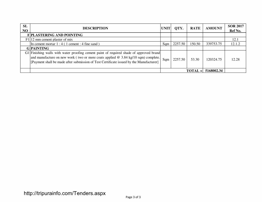
SL
NODESCRIPTION UNIT QTY. RATE AMOUNT
SOR 2017
Ref No.
F PLASTERING AND POINTING
F1 12 mm cement plaster of mix 12.1
In cement mortar 1 : 4 ( 1 cement : 4 fine sand ) Sqm 2257.50 150.50 339753.75 12.1.2
G PAINTING
G1 Finishing walls with water proofing cement paint of required shade of approved brand
and manufacture on new work ( two or more coats applied @ 3.84 kg/10 sqm) complete.
[Payment shall be made after submission of Test Certificate issued by the Manufacturer]Sqm 2257.50 53.30 120324.75 12.28
5168002.34TOTAL =
Page 3 of 3http://tripurainfo.com/Tenders.aspx

SL
NO DESCRIPTION UNIT QTY. RATE AMOUNT
SOR-2017
ITEM NO
A EARTH WORK & METAL PACKING
1 Earth work in excavation by mechanical means (Hydraulic excavator) / manual means in
foundation trenches or drains (not exceeding 1.5 m in width or 10 sqm on plan) including
dressing of sides and ramming of bottoms, lift upto 1.5 m, including getting out the
excavated soil and disposal of surplus excavated soil as directed, within a lead of 50 m.
All kinds of soil Cum 810.00 150.10 121581.00 2.13
2 Filling available excavated earth (excluding rock) in trenches, plinth, sides of foundations
etc. in layers not exceeding 20cm in depth, consolidating each deposited layer by ramming
and watering, lead up to 50 m and lift upto 1.5 m.
All kinds of soil Cum 270.00 116.40 31428.00 2.16
3 Supplying and filling in plinth, under floor, foundations etc. with sand (fine) from local
quarry with all lifts including spreading in horizontal layers, watering, grading to required
slope, ramming, consolidating and compacting each layer by using plate compactor or by
any suitable method complete.
Cum 54.00 615.7 33247.80 2.18
4 Providing and laying dry brick on edge flooring in required pattern complete. Sqm 540.00 628.10 339174.00 10.4
B PLAIN CEMENT CONCRETE
1 Providing and laying in position cement concrete of specified grade excluding the cost of
centring and shuttering -
-All work upto plinth level:
1:3:6 (1 Cement: 3 fine sand : 6 graded stone aggregate 20 mm nominal size) Cum 88.50 7567.60 669732.60 4.1.5
2 Centering shuttering including struttings, propping etc. and removal of form work for: 4.3
Foundations, footings, bases for columns. Sqm 75.00 234.30 17572.50 4.3.1
C REINFORCED CEMENT CONCRETE
1 Providing and laying in position specified grade of reinforced cement concrete excluding
the cost of centring, shuttering, finishing and reinforcement-5.1
-All work upto plinth level:
i) 1:1½:3 ( 1 Cement: 1½ fine sand : 3 graded stone aggregate 20 mm nominal size) Cum 240.00 8439.60 2025504.00 5.1.2
LCS MUHURIGHAT AT BELONIA
DRAIN WORKS
Page 1 of 2http://tripurainfo.com/Tenders.aspx

SL
NO DESCRIPTION UNIT QTY. RATE AMOUNT
SOR-2017
ITEM NO
2 Centering shuttering including struttings, propping etc. and removal of form work for: 5.9
i) Foundations, footings, bases for columns etc. for mass concrete with steel formwork Sqm 1320.00 262.50 346500.00 5.9.1.2
3 Reinforcement for R.C.C. work including straightening, cutting, bending, placing in position
and binding all complete upto floor five level.5.2
i) Thermo-Mechanically Treated bars/ Cold twisted deformed steel bars Kg 21600 59.70 1289520.00 5.20.4
D PLASTERING & PONTING
9 12 mm cement plaster of mix 12.1
In cement mortar 1 : 4 ( 1 cement : 4 fine sand ) Sqm 960.00 150.500 144480.00 12.1.2
5018739.90
15291556.65
5018739.90
20310296.55GRAND TOTAL OF ROAD AND DRAIN WORKS =
GRAND TOTAL =
GRAND TOTAL OF ROAD WORKS =
GRAND TOTAL OF DRAIN WORKS =
Page 2 of 2http://tripurainfo.com/Tenders.aspx

SL
NODESCRIPTION UNIT QTY. RATE AMOUNT
Reference
SOR'2017
1 Excavation in Roadway cutting in soil by using manual means including loadingin
truck and carrying of cut earth to embankment site with all lifts and lead upto 1000
metre as per MoRT&H Technical Specification clauses of section 300
Cum 1919.25 170.30 326848.28 3.1
2 Removal of unsuitable soil including excavation, loading and disposal upto 1000 m
lead with all lifts but excluding compaction ground supporting embankment /
subgrade, replacement by suitable soil, which shall be paid separately as per
MoRT&H Technical Specification clauses of section 300.
Cum 475.00 43.60 20710.00 3.11
3 Construction of subgrade and earthen shoulders with approved material obtained
from borrow pits with all lifts and leads, transporting to site , spreading, grading to
required slope and compacted to meet requirement of Table 300.2 as per MoRT&H
Technical Specification clauses of section 300.
Cum 550.00 167.00 91850.00 3.18
4 Furnishing and laying of the live sods of perennial turf forming grass on
embankment slope , verges or other locations shown on the drawing or as directed
by the Engineer including preparation of ground, fetching of sods and watering as
per MoRT&H Technical Specification clauses of section 300.
Sqm 435.00 41.00 17835.00 3.22
5 Granular Sub-Base with Well Graded Material(using jhama brick aggregate) (Table:-
400.1)
A. By Mix in Place Method
Construction of granular sub-base by providing well graded material (Jhama Brick
Aggregate, as per Table:- 400.1, Grading-I), spreading in uniform layers with tractor
with attachments or motor grader on prepared surface, mixing by mix in place
method with rotavator at OMC, applying and brooming sand to fill up the interstices
of coarse aggregate, wheel roller to achieve the desired density, complete as per
MoRT&H Technical Specification Clause 401.
4.17
i) For Grading- I Material (Jhama brick aggregate) Cum 639.75 4955.10 3170025.23 i
6 Water Bound Macadam Sub-Base / Base using Jhama Brick Aggregate
ROAD WORK
LCS MUHURIGHAT AT BELONIA
Page 1 of 4http://tripurainfo.com/Tenders.aspx

SL
NODESCRIPTION UNIT QTY. RATE AMOUNT
Reference
SOR'2017
1) WBM Grading- 2
Providing, laying, spreading and compacting jhama brick aggregates of specific
sizes to water bound macadam specification including spreading in uniform
thickness, hand packing, rolling with three wheel 80-100 kN static roller / vibratory
roller in stages to proper grade and camber, applying and brooming and binding
materials to fill up the interstices of coarse aggregate, watering and compacting to
the required density Grading-2 as per MoRT&H Technical Specification Clause
4.18
By Manual Means Cum 639.75 4617.50 2954045.63 1A
2) WBM Grading- 3
Providing, laying, spreading and compacting jhama brick aggregates of specific
sizes to water bound macadam specification including spreading in uniform
thickness, hand packing, rolling with three wheel 80-100 kN static roller / vibratory
roller in stages to proper grade and camber, applying and brooming and binding
materials to fill up the interstices of coarse aggregate, watering and compacting to
the required density Grading-3 as per MoRT&H Technical Specification Clause
4.18
By Manual Means Cum 319.88 4591.00 1468546.13 2A
7 Providing and applying primer coat with bitumen emulsion (SS-1) on prepared
surface of granular base including cleaning of road surface and spraying primer at
the rate of 0.6 kg/sqm using mechanical means as per MoRT&H Technical
Specification Clause 502.
Sqm 4265.00 29.10 124111.50 5.1
8 Providing and applying tack coat with bitumen emulsion (RS-1) using emulsion
pressure distributor at the rate of 0.20 kg per sqm on the prepared bituminous /
granular surface cleaned with Hydraulic broom as per MoRT&H Technical
Specification Clause 503.
Sqm 4265.00 9.50 40517.50 5.2
Page 2 of 4http://tripurainfo.com/Tenders.aspx

SL
NODESCRIPTION UNIT QTY. RATE AMOUNT
Reference
SOR'2017
9 Dense Graded Bituminous Macadam
Providing and laying dense graded bituminous macadam with 100-120 TPH batch
type HMP producing an average output of 75 tonnes per hour using crushed
aggregates of specified grading, premixed with bituminous binder @ 4.0 to 4.5 per
cent by weight of total mix and filler, transporting the hot mix to work site, laying
with a hydrostatic paver finisher with sensor control to the required grade, level and
alignment, rolling with smooth wheeled, vibratory and tandem rollers to achieve the
desired compaction as per MoRT&H specification clause No. 507 complete in all
respects.
B Grading-II Cum 396.00 11921.20 4720795.20 5.6 B i
10 Semi-Dense Bituminous Concrete
Providing and laying semi-dense bituminous concrete with 100-120 TPH batch type
HMP producing an average output of 75 tonnes per hour using crushed aggregates
of specified grading, premixed with bituminous binder @ 4.5 to 5.0 per cent by
weight of total mix and filler, transporting the hot mix to work site, laying with a
hydrostatic paver finisher with sensor control to the required grade, level and
alignment, rolling with smooth wheeled, vibratory and tandem rollers to achieve the
desired compaction as per MoRT&H specification clause No. 508 complete in all
respects.B Grading II
ii With Viscocity Graded Bitumen of VG-20. Cum 132.00 12178.00 1607496.00 5.7 B ii
11 Seal Coat
Case - I : Type A
Providing and laying seal coat sealing the voids in a bituminous surface laid to the
specified levels, grade and cross fall using Type A seal coats as per MoRT&H
Technical Specification Clause 513.
i) Bitumen of VG-30 Sqm 4265.00 83.50 356127.50 5.12 A i
Page 3 of 4http://tripurainfo.com/Tenders.aspx

SL
NODESCRIPTION UNIT QTY. RATE AMOUNT
Reference
SOR'2017
12 Painting Lines, Dashes, Arrows etc on Roads in Two Coats on New Work
Painting lines, dashes, arrows etc on roads in two coats on new work with ready
mixed road marking paint conforming to IS:164 on bituminous surface, including
cleaning the surface of all dirt, dust and other foreign matter, demarcation at site and
traffic control as per MoRT&H Technical Specification Clause 803.
i) Over 10 cm in width Sqm 225.00 113.80 25605.00 8.11 i
13 Providing and laying of hot applied thermoplastic compound 2.5 mm thick including
reflectorising glass beads @ 250 gms per sqm area, thickness of 2.5 mm is exclusive
of surface applied glass beads as per IRC:35 . The finished surface to be level,
uniform and free from streaks and holes. as per MoRT&H Technical Specification
Clause 803.
Sqm 98.25 2168.40 213045.30
14 Providing and fixing of retro-reflectorised cautionary, mandatory and informatory
sign as per IRC:67 made of high intensity grade shetting vide MoRT&H technical
specification Clause 801.3, fixed over aluminium sheeting, 1.5 mm thick supported
on a mild steel angle iron post 75 mm x 75 mm x 6 mm firmly fixed to the ground
by means of properly designed foundation with M 15 grade cement concrete 450
mm x 450 mm x 600 mm, 600 mm below ground level as per drawings and
MoRT&H Technical Specification Clause 801.
8.4
a with 900 mm equilateral triangle Nos 10.00 2301.10 23011.00 i)
b with 600 mm circular Nos 10.00 2241.10 22411.00 iii)
c with 800 x 600 mm rectangular Nos 10.00 2417.60 24176.00 iv)
d with 600 x 600 mm square Nos 10.00 2310.10 23101.00 vi)
e with 900 mm octagon Nos 10.00 2589.70 25897.00 vii)
15 Direction and Place Identification Signs upto 0.9 sqm Size Board.
Providing and erecting direction and place identification retro-reflectorised sign as
per IRC:67 made of high intensity grade sheeting vide clause 801.3, fixed over
aluminium sheeting, 2 mm thick with area not exceeding 0.9 sqm supported on a
mild steel single angle iron post 75 x 75 x 6 mm firmly fixed to the ground by
means of properly designed foundation with M15 grade cement concrete 450 x 450
x 600 mm, 600 mm below ground level as per approved drawing and MoRT&H
Technical Specification Clause 801.
Each 12.00 2950.20 35402.40 8.5
15291556.65GRAND TOTAL =
Page 4 of 4http://tripurainfo.com/Tenders.aspx

BILL
NODESCRIPTION AMOUNT
1 Civil Works 15352261.27
2 PEB Works 5411451.68
SUB-TOTAL = 20763712.95
3 Construction of 2 nos Toilet & 2 nos Septic tank 1031857.33
SUB-TOTAL = 21795570.28
LCS MUHURIGHAT AT BELONIA
S U M M A R Y
WARE HOUSE - 2 NOS WITH TOILET
http://tripurainfo.com/Tenders.aspx

SL
NODESCRIPTION UNIT QTY. RATE AMOUNT SOR Ref No.
1 Construction of PEB buildings by using the built up sections are made from hot
rolled platers conforming to ASTM A - 572 GR 50 (345 MPa) and other sections
except beams are mill sections complying with IS : 2062 and the section should be
provided with 2 coats of Zinc Chromate Red Oxide Paint after sand blasting and 2
coats of synthetic enamel paints as per the approved colour. Bracing rods and sag
rods are made of steel bars conforming to IS 2062 with a minimum yield strength of
240 MPa. All the fasteners should be confimed as per the IS 3757 specifications.
The roofing and Fascia board should be ZINC Aluminium alloy coated (Galvalume)
colour roof sheet of 0.47mm nominal thickness, cold roll formed from a cold rolled
coil confirming to ASTM A 792 M Grade 80 with a minimum yield strenght of 550
MPa. The eves gutter should be provided with Zinc Aluminium alloy coated steel
sheet with GI Gutter hangers. Downspouts are should be provided with 100mm size
of Zinc aluminium coated shees with GI Leader straps. The quoted price should
include the supply and fixing chares of MS inserts, base plate, anchor bolt in the
concrete. And also the quoted rate should include all necessary labour charges and
material and machinery charges including all works related the PEB structures
excluding Civil works as per the detailed drawing and instructions of engineer in
charge.
No 2.00 2705725.84 5411451.68
5411451.68
5411451.68GRAND TOTAL =
LCS MUHURIGHAT AT BELONIA
PEB Works
TOTAL =
http://tripurainfo.com/Tenders.aspx

SL
NODESCRIPTION UNIT QTY.
RATE
(SOR-17)AMOUNT
SOR ITEM
NO
1 EART WORK
1.1 Earth work in excavation by mechanical means (Hydraulic excavator) / manual means in
foundation trenches or drains (not exceeding 1.5 m in width or 10 sqm on plan)
including dressing of sides and ramming of bottoms, lift upto 1.5 m, including getting
out the excavated soil and disposal of surplus excavated soil as directed, within a lead of
2.13
-All kinds of soil Cum 86.217 150.10 12941.17
1.2 Filling available excavated earth (excluding rock) in trenches, plinth, sides of
foundations etc. in layers not exceeding 20cm in depth, consolidating each deposited
layer by ramming and watering, lead up to 50 m and lift upto 1.5 m.
2.16
-All kinds of soil Cum 36.461 116.40 4244.06
2 PLAIN CEMENT CONCRETE
2.1 Providing and laying in position cement concrete of specified grade excluding the cost
of centring and shuttering -4.1
-All work upto plinth level:
1:3:6 ( 1 Cement: 3 fine sand : 6 graded stone aggregate 20 mm nominal size) Cum 22.318 7567.6 168891.80 4.1.5
3 RCC WORKS
3.1 Providing and laying in position specified grade of reinforced cement concrete
excluding the cost of centring, shuttering, finishing and reinforcement-5.1
-All work upto plinth level:
1:1½:3 ( 1 Cement: 1½ fine sand : 3 graded stone aggregate 20 mm nominal size) - cover slab
and perforated slabCum 9.978 8439.60 84210.33 5.1.2
3.2 Reinforced cement concrete work in walls (any thickness), including attached pilasters,
buttresses, plinth and skirting courses, fillets, columns, pillars, piers, abutments, posts
and struts etc. upto floor five level excluding cost of centring, shuttering, finishing and
reinforcement
5.20
In plinth and skirting courses, fillets, columns, pillars, posts and struts. 5.2.2
1:1½:3 ( 1 Cement: 1½ fine sand : 3 graded stone aggregate 20 mm nominal size). Cum 1.575 8967.30 14123.50 5.2.2.2
LCS MUHURIGHAT AT BELONIA
ABSTRACT OF TOILET & SEPTIC TANK
1 of 7
http://tripurainfo.com/Tenders.aspx

SL
NODESCRIPTION UNIT QTY.
RATE
(SOR-17)AMOUNT
SOR ITEM
NO
3.3 Reinforced cement concrete work in beams, suspended floors, roofs having slope upto
15° landings, balconies, shelves, chajjas, lintels, bands, plain window sills, staircases
and spiral stair cases upto floor five level excluding the cost of centring, shuttering,
finishing and reinforcement-
5.3
RCC work in suspended floors, roofs having slope upto 15° landings, balconies, shelves
and chajjas.5.3.1
1:1½:3 ( 1 Cement: 1½ fine sand : 3 graded stone aggregate 20 mm nominal size) Cum 5.872 8841.00 51915.46 5.3.1.2
3.4 Centering shuttering including struttings, propping etc. and removal of form work for: 5.9
a) Foundations, footings, bases for columns etc. for mass concrete with timber plank Sqm 10.305 226.10 2329.96 5.9.1.1
b) Suspended floors, roofs, landings, balconies and access platform with 12 mm thick
shuttering plySqm 52.1475 452.10 23575.88 5.9.4.2
c) Lintels, beams, plinth beams, girders, bressumers and cantilevers with shuttering ply Sqm 13.68 327.70 4482.94 5.9.5.1
d) Columns, Pillars, Piers, Abutments, Posts and Struts with shuttering ply Sqm 6.30 429.30 2704.59 5.9.6.1
3.5 REINFORCEMENT
3.5.1 Reinforcement for R.C.C. work including straightening, cutting, bending, placing in
position and binding all complete upto floor five level.5.20
a) Thermo-Mechanically Treated bars/ Cold twisted deformed steel bars. Kg 1655.38 59.70 98825.89 5.20.4
4 MASONRY WORK
4.1 First class brick work in foundation and plinth including cost of all materials as required
complete:-6.1
a. In cement mortar 1:5 ( 1 cement : 5 fine sand ). Cum 14.706 5278.50 77626.94 6.1.4
4.2 First class brick work in superstructure above plinth level & upto floor-five level
including cost of all materials as required complete:-6.3
In cement mortar 1:5 ( 1 cement : 5 fine sand ). Cum 12.1875 5800.20 70689.94 6.3.4
4.3 Half brick masonry work with first class bricks in foundation and plinth including cost
of all materials as required complete:-6.10
In cement mortar 1:5 ( 1 cement : 5 fine sand ). Sqm 27.615 717.70 19819.29 6.10.3
2 of 7
http://tripurainfo.com/Tenders.aspx

SL
NODESCRIPTION UNIT QTY.
RATE
(SOR-17)AMOUNT
SOR ITEM
NO
5 WOOD & PVC WORK
5.1 Providing and fixing factory made UPVC door frame made of UPVC extruded, section
having an overall dimension, as below (tolerance +/- 1mm) with wall thickness 2.0mm+/-
02mm. corners of the door frame to be jointed with galvanized brackets and stainless
screws, joint mitred and plastic wilded. The hinge side vertical of the frames reinforced
by galvanized MS tube of size 19 × 19 mm and 1 mm +/- 0.1 mm wall thickness and 3
nos stainless steel hinges fixed to the frame complete as per manufacturers specification
and direction of Engineer-In-Charge.
8.114
a) Extruded section Profile size 48x40 mm. Rmt 19.800 246.50 4880.70 8.114.1
5.2 24 mm thick factory made PVC door shutters made of styles and rails of a UPVC
hollow section of size 59x24 mm and wall thickness 2 mm ± 0.2 mm with inbuilt edging
on both sides. The styles and rails mitred and joined at the corners by means of M.S.
galvanised /plastic brackets of size 75×220 mm having wall thickness 1.0 mm and
stainless steel screws. The styles of the shutter reinforced by inserying galvanised MS
tube of size 20×20 mm and 1 mm ± 0.1 mm wall thickness. The lock rail made up of
"H" Section, a UPVC hollow section of size 100×24 mm and 2 mm ± 0.2 mm wall
thickness fixed to the shutter styles by means of plastic /galvanised MS "U" cleats. The
shutter frame filled with a UPVC multi-chambered single panel of size not less than 620
mm, having overall thickness of 20 mm and 1 mm ± 0.1 mm wall thickness. The panels
filled vertically and tie bar at two places by inserting horizontaly 6 mm galvanised MS
rod and fastened with nuts and washers, complete as per manufacturer's specification
and direction of Engineer-In-Charge. (for W.C. and Bathroom door shutter).
Sqm 6.300 1815.60 11438.28 8.115.1
6 FINISHING WORK
6.1 12mm Cement plaster of mix 12.1
i) In cement mortar 1 : 5 ( 1 cement : 5 fine sand ) Sqm 46.975 142.90 6712.73 12.1.3
6.2 15mm Cement plaster of mix 12.2
i) In cement mortar 1 : 5 ( 1 cement : 5 fine sand ) Sqm 53.21 165.60 8811.58 12.2.3
6.3 6 mm cement plaster of mix : 12.4
i) In cement mortar 1 : 4 ( 1 cement : 4 fine sand ) Sqm 27.24 135.30 3685.57 12.4.2
6.4 Neat cement punning. Sqm 46.185 44.30 2046.00 12.50
3 of 7
http://tripurainfo.com/Tenders.aspx

SL
NODESCRIPTION UNIT QTY.
RATE
(SOR-17)AMOUNT
SOR ITEM
NO
6.5 Distempering with oil bound washable distemper of approved brand and manufacture
and of required shade on new work ( two or more coats ), over and including water
thinable priming coat to give an even shade. (Payment shall be made after submission of
Test Certificate issued by Manufacturer)
Sqm 18.02 92.60 1668.65 12.24
6.6 Finishing walls with acrylic smooth exterior paint of required shade of approved brand
and manufacture on new work ( two or more coats applied @ 1.67 kg/10 sqm ) over and
including base coat water proofing cement paint applied @ 2.20 kg/10 sqm complete.Sqm 122.43 93.20 11410.01 12.31
7 FLOORING
7.1 Providing and laying polished vitrified floor tiles in different sizes (thickness to be
specified by the manufacturer) with water absorption less than 0.08 % and conforming
to IS : 15622 of approved make in all colours, shades over 20 mm thick bed of cement
mortar 1 : 4 ( 1 cement : 4 fine sand ) jointed with ordinary cement slurry including
pointing with white cement mixed with pigment of matching shade complete.
10.42
a) Size of tile 50x50 cm Sqm 8.58 979.40 8403.25 10.42.1
7.2 Providing and fixing 1st quality ceramic glazed wall tiles conforming to IS : 15622 (
thickness to be specified by the manufacturer ) of approved make in all colours, shades
of any size as approved by Engineer-in-charge in skirting, risers of steps and dados over
12 mm thick bed of cement mortar 1 : 3 ( 1 cement : 3 fine sand ) jointed with ordinary
cement slurry including pointing with white cement mixed with pigment of matching
shade complete.
Sqm 17.40 677.5 11788.50 10.38
8 WATERPROOFING
Providing and laying water proofing treatment to vertical and horizontal surfaces of
depressed portions of W.C., kitchen and the like as required as per direction of the
Engineer-in-charge,consisting of :
Sqm 77.200 504.10 38916.52 17.3
(i) 1st course of applying cement slurry @ 4.4 kg/sqm mixed with water proofing
compound conforming to IS 2645 in recommended proportions including rounding off
junction of vertical and horizontal surface.
(ii) 2nd course of 20 mm cement plaster 1:3 (1 cement : 3 fine sand) mixed with water
proofing compound in recommended proportion including rounding off junction of
vertical and horizontal surface.
4 of 7
http://tripurainfo.com/Tenders.aspx

SL
NODESCRIPTION UNIT QTY.
RATE
(SOR-17)AMOUNT
SOR ITEM
NO
(iii) 3rd course of applying blown or residual bitumen applied hot at 1.7 kg. per sqm of
area.
(iv) 4th course of 400 micron thick PVC sheet. (Overlaps at joints of PVC sheet should
be 100 mm wide and pasted to each other with bitumen @ 1.7 kg/ sqm). [Payment shall
be made after submission of the product performance shall carry guaranteed for 10 years
against any leakage]
9 PLUMBING AND SANITARY
9.1 Providing and fixing water closet squatting pan (Indian type W.C. pan ) with 100mm
sand cast Iron P or S trap, 10 litre low level white P.V.C. flushing cistern with manually
controlled device (handle lever) conforming to IS : 7231, with all fittings and fixtures
complete including cutting and making good the walls and floors wherever required :
18.1
White Vitreous china Orrisa pattern W.C. pan of size 580x440 mm with integral type
foot rests.Nos 4.000 3842.50 15370.00 18.1.1
9.2 Providing and fixing wash basin with C.I. brackets, 15 mm C.P. brass pillar taps,32 mm
C.P. brass waste of standard pattern, including painting of fittings and brackets, cutting
and making good the walls wherever require :
18.7
White Vitreous China Wash basin size 630x450 mm with a single 15 mm C.P. brass
pillar taps.Nos 4.000 1897.30 7589.20 18.7.2
9.3 Providing and fixing G.I. inlet connection for flush pipe connecting with W.C. pan. Nos 4.000 107.20 428.80 18.22
9.4 Providing and fixing Chlorinated Polyvinyl Chloride (CPVC) pipes, having thermal
stability for hot & cold water supply including all CPVC plain & brass threaded fittings
i/c fixing the pipe with clampsat 1.00 m spacing. This includes jointing of pipes &
fittings with one step CPVC solvent cement and the cost of cutting chases and making
good the same including testing of joints complete as per direction of Engineer in
19.8
Concealed work including cutting chases and making good the walls etc.
a) 15 mm nominal outer dia. Pipes Mtr. 16.000 277.80 4444.80 19.8.1
b) 25 mm nominal outer dia. Pipes Mtr. 16.000 350.50 5608.00 19.8.3
9.5 Providing and fixing PTMT bib cock of approved quality and colour. 19.54
i) 15 mm nominal bore, 122 mm long, weighing not less than 99 gms. Nos 4.000 192.80 771.20 19.54.2
9.6 Providing and fixing PTMT stop cock of approved quality and colour. 19.55
i) 15 mm nominal bore, 86mm long, weighing not less than 88 grams. Nos 4.000 131.50 526.00 19.55.1
5 of 7
http://tripurainfo.com/Tenders.aspx

SL
NODESCRIPTION UNIT QTY.
RATE
(SOR-17)AMOUNT
SOR ITEM
NO
9.7 Providing and fixing PTMT pillar cock of approved quality and colour. 19.56
i) 15mm nominal bore, 107mm long, weighing not less than 110 grams. Nos 4.000 185.50 742.00 19.56.1
9.8 Providing and placing on terrace (at all floor levels) polyethylene water storage tank ISI
: 12701 marked with cover and suitable locking arrangement and making necessary
holes for inlet, outlet and overflow pipes but without fittings and the base support for
Ltr. 4000.00 9.50 38000.00 19.48
9.9 Providing and fixing on wall face unplasticised Rigid PVC rain water pipes (working
pressure 4 kg / cm2) conforming to IS : 13592 Type A including jointing with seal ring
conforming to IS : 5382 leaving 10 mm gap for thermal expansion:
18.82
a) Single socketed pipe - 75 mm OD Mtr. 10.000 142.30 1423.00 18.82.1
b) Single socketed pipe - 110 mm OD Mtr. 10.000 239.00 2390.00 18.82.2
9.10 Providing and fixing on wall face unplasticised - PVC moulded fittings/ accessories for
unplasticised Rigid PVC rain water pipes conforming to IS : 13592 Type A including
jointing with seal ring conforming to IS : 5382 leaving 10 mm gap for thermal
18.84
a) Coupler 18.84.1
i) 75 mm Nos 4.000 57.9 231.60 18.84.1.1
ii) 110 mm Nos 4.000 99.00 396.00 18.84.1.2
b) Single equal tee without door 18.84.3
i) 75 mm Nos 4.000 107.40 429.60 18.84.3.1
ii) 110 mm Nos 4.000 175.10 700.40 18.84.3.2
c) Single equal tee with door 18.84.4
i) 75 mm Nos 4.000 125.60 502.40 18.84.4.1
ii) 110 mm Nos 4.000 190.80 763.20 18.84.4.2
d) Bend 87.5° 18.84.5
i) 75 mm Nos 4.000 70.00 280.00 18.84.5.1
ii) 110 mm Nos 4.000 109.80 439.20 18.84.5.2
6 of 7
http://tripurainfo.com/Tenders.aspx

SL
NODESCRIPTION UNIT QTY.
RATE
(SOR-17)AMOUNT
SOR ITEM
NO
10 Sewage and Drainage
10.1 Constructing brick masonry chamber for underground C.I. inspection chamber and
bends with 1st class bricks in cement mortar 1:4 (1 cement : 4 fine sand) C.I. cover with
frame (light duty) 455x610 mm internal dimensions, total weight of cover with frame to
be not less than 38 kg (weight of cover 23 kg and weight of frame 15 kg) R.C.C. top
slab with 1:2:4 mix (1 cement :2 fine sand : 4 graded stone aggregate 20 mm nominal
size) foundation concrete 1:5:10 (1 cement: 5 fine sand : 10 graded stone aggregate 40
mm nominal size), inside plastering 12 mm thick with cement mortar 1:3 (1 cement: 3
fine sand) finished smooth with a floating coat of neat cement on walls and bed concrete
etc. complete as per standard design :
20.8
10.1.1 Inside dimensions 455x610 mm and 45 cm deep for single pipe line Each 4.000 6073.60 24294.40 20.8.1
10.2 Making soak pit 2.5 m diameter 3.0 metre deep with 45 x 45 cm dry brick honey comb
shaft with well burnt 2nd class bricks and S.W. drain pipe 100 mm diameter, 1.8 m long
complete as per standard design
Each 4.000 45096.00 180384.00 20.1
1031857.33GRAND TOTAL =
7 of 7
http://tripurainfo.com/Tenders.aspx

SL
NODESCRIPTION UNIT QTY.
RATE
(SOR-17)AMOUNT
SOR ITEM
NO
1 EARTH WORK
1.01 Surface dressing of the ground including removing vegetation and in-equalities not
exceeding 15 cm deep and disposal of rubbish, lead upto 50 m and lift upto 1.5 m.2.4
-All kinds of soil Sqm 1200.00 12.10 14520.00
1.02 Earth work in excavation by mechanical means (Hydraulic excavator) / manual means
in foundation trenches or drains (not exceeding 1.5 m in width or 10 sqm on plan)
including dressing of sides and ramming of bottoms, lift upto 1.5 m, including getting
out the excavated soil and disposal of surplus excavated soil as directed, within a lead
of 50 m.
-All kinds of soil Cum 1105.00 150.10 165860.50 2.13
1.03 Filling available excavated earth (excluding rock) in trenches, plinth, sides of
foundations etc. in layers not exceeding 20cm in depth, consolidating each deposited
layer by ramming and watering, lead up to 50 m and lift upto 1.5 m.
-All kinds of soil Cum 590.00 116.40 68676.00 2.16
1.05 Supplying and filling in plinth, under floor, foundations etc. with sand (fine) from
local quarry with all lifts including spreading in horizontal layers, watering, grading to
required slope, ramming, consolidating and compacting each layer by using plate
compactor or by any suitable method complete.
Cum 195.00 615.70 120061.50 2.18
1.06 Supplying chemical emulsion in sealed containers including delivery as specified. 2.19
Chlorpyriphos/Lindane emulsifiable concentrate of 20% Ltr. 95.00 287.60 27322.00 2.19.1
1.07 Treatment of soil under plinth filling using chemical emulsion @ 1 litre per hole 300
mm apart including drilling 12mm dia holes and plugging with sand filling.2.20.3
With Chlorpyriphos/Lindane E.C. 20% with 1% concentration. Sqm 750.00 48.80 36600.00 2.20.3.1
ABSTRACT OF CIVIL WORKS
LCS MUHURIGHAT AT BELONIA
Page 1 of 5http://tripurainfo.com/Tenders.aspx

SL
NODESCRIPTION UNIT QTY.
RATE
(SOR-17)AMOUNT
SOR ITEM
NO
2 PLAIN CEMENT CONCRETE WORK.
2.01 Providing and laying in position cement concrete of specified grade excluding the cost
of centring and shuttering -4.1
-All work upto plinth level:
a) 1:3:6 ( 1 Cement: 3 fine sand : 6 graded stone aggregate 20 mm nominal size) Cum 414.00 7567.60 3132986.40 4.1.5
2.02 Providing and laying damp-proof course with cement concrete 1:2:4 (1 cement: 2
coarse sand : 4 graded stone aggregate 12.5mm/20mm nominal size). 4.5.1
a) D.P.C 50mm thick Sqm 70.00 460.40 32228.00 4.5.1.2
2.03 Centering shuttering including struttings, propping etc. and removal of form work for: 4.3
a) Foundations, footings, bases for columns etc. for mass concrete with steel formwork. Sqm 905.00 234.30 212041.50 4.3.1
3 R.C.C WORKS
3.01 Providing and laying in position specified grade of reinforced cement concrete
excluding the cost of centring, shuttering, finishing and reinforcement.5.1
-All work upto plinth level:
a) 1:1½:3 ( 1 Cement: 1½ fine sand : 3 graded stone aggregate 20 mm nominal size). Cum 157.00 8439.60 1325017.20 5.1.2
3.02 Reinforced cement concrete work in walls (any thickness), including attached
pilasters, buttresses, plinth and skirting courses, fillets, columns, pillars, piers,
abutments, posts and struts etc. upto floor five level excluding cost of centring,
shuttering, finishing and reinforcement.
5.2
In walls (any thickness), including attached pilasters, buttresses, piers, abutments etc. 5.2.1
1:1½:3 ( 1 Cement: 1½ fine sand : 3 graded stone aggregate 20 mm nominal size) Cum 38.00 8708.70 330930.60 5.2.1.2
3.03 In plinth and skirting courses, fillets, columns, pillars, posts and struts. 5.2.2
1:1½:3 ( 1 Cement: 1½ fine sand : 3 graded stone aggregate 20 mm nominal size) Cum 22.50 8967.30 201764.25 5.2.2.2
3.04 Reinforced cement concrete work in beams, suspended floors, roofs having slope upto
15° landings, balconies, shelves, chajjas, lintels, bands, plain window sills, staircases
and spiral stair cases upto floor five level excluding the cost of centring, shuttering,
finishing and reinforcement-
5.3
RCC work in suspended floors, roofs having slope upto 15° landings, balconies,
shelves and chajjas.5.3.1
1:1½:3 ( 1 Cement: 1½ fine sand : 3 graded stone aggregate 20 mm nominal size) Cum 77.00 8841.00 680757.00 5.3.1.2
Page 2 of 5http://tripurainfo.com/Tenders.aspx

SL
NODESCRIPTION UNIT QTY.
RATE
(SOR-17)AMOUNT
SOR ITEM
NO
3.05 Reinforcement for R.C.C. work including straightening, cutting, bending, placing in
position and binding all complete upto floor five level.5.20
a) Thermo-Mechanically Treated bars/ Cold twisted deformed steel bars. Kg 63050.00 59.70 3764085.00 5.20.4
3.06 Centering shuttering including struttings, propping etc. and removal of form work for: 5.9
a) Foundations, footings, bases for columns etc. for mass concrete with Timber Plank Sqm 243.00 226.10 54942.30 5.9.1.1
b) Walls (any thickness), including attached pilasters, buttresses, plinth and string courses
etc. using shuttering ply
Sqm132.25 327.80 43351.55 5.9.3
c) Lintels, beams, plinth beams, girders, bressumers and cantilevers with shuttering ply. Sqm 184.00 327.70 60296.80 5.9.5.1
d) Columns, Pillars, Piers, Abutments, Posts and Struts with shuttering ply. Sqm 225.50 429.30 96807.15 5.9.6.1
4 BRICK WORK
4.01 First class brick work in foundation and plinth including cost of all materials as
required complete:-6.1
i) In Cement mortar 1:5 ( 1 cement : 5 fine sand ) Cum 300.00 5278.50 1583550.00 6.1.4
4.02 First class brick work in superstructure above plinth level & upto floor-five level
including cost of all materials as required complete:-6.3
i) In Cement mortar 1:5 ( 1 cement : 5 fine sand ) Cum 171.00 5800.20 991834.20 6.3.4
4.03 Half brick masonry work with first class bricks in foundation and plinth including cost
of all materials as required complete:-6.10
In Cement mortar 1:4 ( 1 cement : 4 fine sand ) Sqm 125.00 717.70 89712.50 6.10.3
5.0 WOOD WORK
5.01 Providing wood work in frames of Door, Ventilator, Clerestory window and other
frame, wrought framed and fixed in possition:8.1
a) Local teak wood Cum 1.20 54568.30 65481.96 8.1.3
5.02 Providing and fixing panelled / or panelled and glazed shutters for doors, windows and
clerestory windows including ISI marked bright finished / black enamelled M.S butt
hinges with necessary screws excluding panelling and or glazing, which will be paid
for separately but including the wooden beading of 20 × 12 mm for fixing panelling
and or glazing as per direction of Engineer-In-Charge.
8.5
Local teak wood 8.5.1
a) 35 mm thick shutters Sqm 5.00 1319.00 6595.00 8.5.1.1
Page 3 of 5http://tripurainfo.com/Tenders.aspx

SL
NODESCRIPTION UNIT QTY.
RATE
(SOR-17)AMOUNT
SOR ITEM
NO
6 STEEL WORK & ALUMINIUM WORK;
6.01 Supplying and fixing rolling shutters of approved make, made of required size M.S.
laths interlocked together through their entire length and jointed together at the end by
end locks mounted on specially designed pipe shaft with brackets, side guides and
arrangements for inside and outside locking with push and pull operation complete
including the cost of providing and fixing necessary 275mm long wire springs grade
No.2 and M.S. top cover of required thickness for rolling shutters & with handles, hold
fast including embedding in cement concrete of required grade required for fixing in
position, all necessary fittings, including applying of approved steel primer etc.
complete as required:-
9.6
a) 80xl.25mm M.S. laths with 1.25 mm thick top cover. Sqm 115.00 2420.30 278334.50 9.6.1
6.02 Providing and fixing ball bearing for rolling shutters ( exceeding 10 sqm area ) of
approved make complete as required.Nos 2.00 407.00 814.00 9.7
6.04 Providing and fixing aluminium work for doors,windows, ventilators and partitions
with extruded built up standard tubular sections/ appropriate Z sections and other
sections of approved make conforming to IS:733 and IS : 1285, fixing with dash
fasteners of required dia and size, including necessary filling up of gaps at junctions,
i.e. at top, bottom and sides with required EPDM rubber/neoprene gasket etc.
Aluminium sections shall be smooth, rust free, straight, mitred and jointed
mechanically wherever required including cleat angle, aluminium snap beading for
glazing / paneling, C.P. brass/stainless steel screws, all complete as per architectural
drawing and the direction of Engineer incharge.(Glazing and paneling and dash
16.1
For fixed portion of approved quality:- 16.1.1
a) Powder coated aluminium ( minimum thickness of powder coating of 50 micron ). Kg 352.51 396.80 139876.76 16.1.1.2
6.05 Providing and fixing glazing of approved quality in aluminium doors, windows,
ventilator, shutters and partition etc. with EPDM rubber / neoprene gasket etc.
complete as per architectural drawing and the direction of Engineer-in-charge (Cost of
snap beading shall be paid in basic item) :-
16.13
With glass/ float glass panes of 4.0 m thickness (weight not less than 10.0 kg /sqm). Sqm 750.00 881.40 661050.00 16.13.1
Page 4 of 5http://tripurainfo.com/Tenders.aspx

SL
NODESCRIPTION UNIT QTY.
RATE
(SOR-17)AMOUNT
SOR ITEM
NO
7 FLOORING
7.01 Providing and laying cement concrete 1:2:4 (1 cement: 2 fine sand : 4 graded stone
aggregate) flooring finished with a floating coat of neat cement including cement
slurry, rounding of edges and strips and cost of glass strips etc. complete.
10.5
i) 40 mm thick Sqm 750.00 481.50 361125.00 10.5.1
7.02 Providing and fixing precast chequered terrazo tiles 22 mm thick with graded marble
chips of size upto 6 mm, laid on floors, footpath & courtyard on 20 mm thick bed of
cement mortar 1 : 4 ( 1 cement : 4 fine sand ) jointed with neat cement slurry mixed
with pigment to match the shade of tiles including rubbing and polishing complete.
Sqm
600.00 727.50 436500.00 10.55
9 FINISHING WORKS
9.01 12mm Cement plaster of mix 12.1
i) In cement mortar 1 : 5 ( 1 cement : 5 fine sand ) Sqm 480.00 142.90 68592.00 12.1.3
9.02 15mm Cement plaster of mix 12.2
i) In cement mortar 1 : 5 ( 1 cement : 5 fine sand ) Sqm 1070.00 165.60 177192.00 12.2.3
9.03 Neat cement punning. Sqm 144.00 44.30 6379.20 12.5
9.04 Distempering with oil bound washable distemper of approved brand and manufacture
and of required shade on new work ( two or more coats ), over and including water
thinable priming coat to give an even shade. (Payment shall be made after submission
of Test Certificate issued by Manufacturer)
Sqm 1070.00 92.60 99082.00 12.24
9.05 Finishing walls with premium acrylic smooth exterior paint of required shade of
approved brand and manufacture on new work ( two or more coats applied @ 1.43
kg/10 sqm ) over and including priming coat of exterior primer applied @ 2.20 kg/10
sqm complete. (Payment shall be made after submission of Test Certificate issued by
Manufacturer)
Sqm 192.00 93.20 17894.40 12.31
15352261.27GRAND TOTAL =
Page 5 of 5http://tripurainfo.com/Tenders.aspx

SL NO DESCRIPTION ESTIMATE VALUE REMARKS
1 Water Supply Distribution Network 1729929.15
2 Construction of UG Sump - 330 KL 2066631.01
3 Iron Removal Plant 894200.00
4 Pump house Plumbing work 130596.25
5 Construction of Pump House 758148.56
6 Pump House Submersible pump 25000.00
7 Deep tube well 528469.46
8 Pump House 398916.00
GRAND TOTAL = 6531890.43
LCS MUHURIGHAT AT BELONIA
SUMMARY WATER SUPPLY WORKS
http://tripurainfo.com/Tenders.aspx

SL
NODESCRIPTION UNIT QTY. RATE AMOUNT
DWS-2015
ITEM NO
1 Drilling and boring pilot hole in any soil strata by Drilling rig, collection of soil samples
of different strata met with during drilling at various suitable levels, preservation of
samples in polythene bags/sample boxes and disposal of excess soil or mud, including the
cost for bentonite, water etc. as required to maintain the pilot hole properly as per
specification (IS:2800 (Part-I) and direction of the Engineer-in-charge.
(6B)
6.1
ii) 200 mm dia Mtr 40 1163.7 1203.70 A i
2 Reaming of pilot hole to an enlarged bore hole in any soil strata by drilling rig, disposal
of excess soil or mud, including the cost for bentonite, water etc. as required to maintain
the bore hole properly as per specification (IS : 2800 (Part- I) and direction of the
Engineer- in -charge.
6.2
A with contractors rig A
i From 200 mm dia pilot hole to 550 mm Mtr 15 1225.3 18379.50 i
ii From 200 mm dia pilot hole to 460 mm Mtr 25 783.3 19582.50 ii
3 Washing of enlarged bore hole of 460-550 mm dia in any soil strata by drilling
rig,disposal of excess soil or mud, including the cost for bentonite, water etc. as required
to maintain the bore hole properly including lifting of drill piper as per specification (IS:
2800 (Part-I) and direction of the Engineer-in-charge
6.3
A with contractors rig Mtr 40 92.20 3688.00 A
4 Lowering of ERW pipe with drilling rig including painting with anti-corrosive bitumastic
paints, fixing of M.S ring, welding of all joints etc. complete after washing of the bore
hole as per specification (IS : 2800 (Part-I) and direction of the Engineer-in- charge.
6.4
A with contractors rig A
a) 300 mm dia ERW Housing Pipe Mtr 15 416.10 6241.50 i
b) 200 mm dia ERW Blind Pipe Mtr 15 328.00 4920.00 ii
c) 200mm dia ERW Slotted pipe Mtr 10 328.00 3280.00 iii
SINKING OF 1 NO.300MM X 200MM DIA DEEP TUBE WELL BY REVERSE ROTARY RIG METHOD
LCS MUHURIGHAT AT BELONIA
Page 1 of 4http://tripurainfo.com/Tenders.aspx
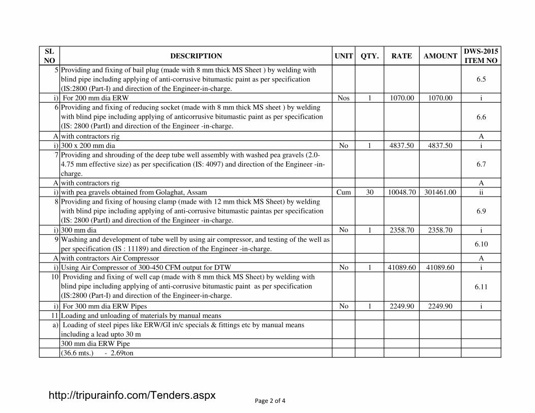
SL
NODESCRIPTION UNIT QTY. RATE AMOUNT
DWS-2015
ITEM NO
5 Providing and fixing of bail plug (made with 8 mm thick MS Sheet ) by welding with
blind pipe including applying of anti-corrusive bitumastic paint as per specification
(IS:2800 (Part-I) and direction of the Engineer-in-charge.
6.5
i) For 200 mm dia ERW Nos 1 1070.00 1070.00 i
6 Providing and fixing of reducing socket (made with 8 mm thick MS sheet ) by welding
with blind pipe including applying of anticorrusive bitumastic paint as per specification
(IS: 2800 (PartI) and direction of the Engineer -in-charge.
6.6
A with contractors rig A
i) 300 x 200 mm dia No 1 4837.50 4837.50 i
7 Providing and shrouding of the deep tube well assembly with washed pea gravels (2.0-
4.75 mm effective size) as per specification (IS: 4097) and direction of the Engineer -in-
charge.
6.7
A with contractors rig A
i) with pea gravels obtained from Golaghat, Assam Cum 30 10048.70 301461.00 ii
8 Providing and fixing of housing clamp (made with 12 mm thick MS Sheet) by welding
with blind pipe including applying of anti-corrusive bitumastic paintas per specification
(IS: 2800 (PartI) and direction of the Engineer -in-charge.
6.9
i) 300 mm dia No 1 2358.70 2358.70 i
9 Washing and development of tube well by using air compressor, and testing of the well as
per specification (IS : 11189) and direction of the Engineer -in-charge.6.10
A with contractors Air Compressor A
i) Using Air Compressor of 300-450 CFM output for DTW No 1 41089.60 41089.60 i
10 Providing and fixing of well cap (made with 8 mm thick MS Sheet) by welding with
blind pipe including applying of anti-corrusive bitumastic paint as per specification
(IS:2800 (Part-I) and direction of the Engineer-in-charge.
6.11
i) For 300 mm dia ERW Pipes No 1 2249.90 2249.90 i
11 Loading and unloading of materials by manual means
a) Loading of steel pipes like ERW/GI in/c specials & fittings etc by manual means
including a lead upto 30 m
300 mm dia ERW Pipe
(36.6 mts.) - 2.69ton
Page 2 of 4http://tripurainfo.com/Tenders.aspx

SL
NODESCRIPTION UNIT QTY. RATE AMOUNT
DWS-2015
ITEM NO
200 mm dia ERW Pipe
(103.70 mts - 3.79 ton
200 mm dia ERW slotted Pipe
(36.6 mts) - 1.34 ton
Ton 7.82 91.60 716.31
b) Unloading of steel pipes like ERW/GI in/c specials & fittings etc by manual means
including a lead upto 50 m
300 mm dia ERW Pipe
(36.6 mts.) - 2.69ton
200 mm dia ERW Pipe
(103.70 mts - 3.79 ton
200 mm dia ERW slotted Pipe
(36.6 mts) - 1.34 ton
Ton 7.82 95.60 747.59
c) Haulage of materials by mechanical means excluding loading & Unloading.
i) Surface road t.km 391.59 2.30 900.66
12 Loading and unloading of materials of manual means.
a) Loading of stone aggregate, brick agreegate, Gravels etc. by manual means within a lead
upto 50m.
Pea Gravels Cum 30 56.80 1704.00
b) Unloading of stone aggregate, brick agreegate, Gravels etc. by manual means within a
lead upto 50m.
Pea Gravels Cum 30 29.90 897.00
c) Haulage of materials by mechanical means excluding loading & Unloading.
i) Surface road t.km 2190 2.30 5037.00
Page 3 of 4http://tripurainfo.com/Tenders.aspx

SL
NODESCRIPTION UNIT QTY. RATE AMOUNT
DWS-2015
ITEM NO
B) COST OF MATERIALS
i) ERW Pipe : ERW pipe should be of FE 410 mild steel casing/housing/slotted
pipes.Heavy grade, screwed and socketed, automatic fusion of electrical resistance of
high frequency induction welded, IS marked
1 Cost of 300 mm dia ERW Housing pipe Mts. 15 3770.00 56550.00
2 Cost of200 mm dia ERW Blind pipe Mts. 15 1851.00 27765.00
3 Cost of 200 mm dia ERW Slotted pipe Mts. 10 2379.00 23790.00
528469.46TOTAL =
Page 4 of 4http://tripurainfo.com/Tenders.aspx

S.NO. DESCRIPTION OF ITEM UNIT QUANTITY RATE AMOUNT DWS 2015
ITEM NO
1 Supply,installation and commissioning of package type Iron Removal Plant
comprising of Iron Removal Filter of dual media filter with anthracite coal, filter
gravel, polypropelene double hexagonal nut stainer etc., mixing chamber for
coagulants like sodium, metering pump for coagulant dosing, air compressor of
suitable capacity with motor, back washing arrangements, disinfection with
sodium hypochlorite solution through metering pump, all necessary pipes for
raw water collection, interconnecting all the chambers, delivery outlet of 150
mm dia along with all related civil, mechanical and Electrical works etc.
complete as per approved drawing, process flow, technical specification and
direction of the engineer-in-charge.
11.1
5000 G.P.H capacity. No 1.00 894200.00 894200.00 C
894200.00TOTAL =
IRON REMOVAL PLANT
LCS MUHURIGHAT AT BELONIA
Page 1 of 1http://tripurainfo.com/Tenders.aspx

SL
NODESCRIPTION UNIT QTY. RATE AMOUNT
SOR 2017
ITEM NO
1 Earth Work & Refilling
Earth work in excavation by mechanical means (Hydraulic excavator) / manual means in
foundation trenches or drains (not exceeding 1.5 m in width or 10 sqm on plan) including
dressing of sides and ramming of bottoms, lift upto 1.5 m, including getting out the excavated
soil and disposal of surplus excavated soil as directed, within a lead of 50 m.
2.13
a. All kinds of soil Cum 15.00 150.10 2251.50
2 Pipe Laying (4 Kg/cm2)
Providing and fixing on wall face unplasticised Rigid PVC rain water pipes (working pressure
4 kg/cm2) conforming to IS : 13592 Type A including jointing with seal ring conforming to
IS : 5382 leaving 10 mm gap for thermal expansion:
11.42
a Pumping & Delivery Line - 75mm OD - PVC pipe Rmt 12.50 142.30 1778.75 11.42.1
b Sok pit line ( Toilet to Soak pit ) - 110mm OD - PVC pipe Rmt 18.00 239.00 4302.00 11.42.2
c Waste Water Soak pit Chamber - 75mm OD - PVC pipe Rmt 14.00 100.40 1405.60 11.42.1
3 FITTINGS:-
Providing and fixing on wall face unplasticised - PVC moulded fittings/ accessories for
unplasticised Rigid PVC rain water pipes conforming to IS : 13592 Type A including jointing
with seal ring conforming to IS : 5382 leaving 10 mm gap for thermal expansion:
11.43
a Bend 87.5° 11.43.5
i) 110mm Each 12.00 109.80 1317.60 11.43.5.2
ii) 75mm Each 12.00 70.00 840.00 11.43.5.1
b Single equal tee with door 11.43.4
i) 110mm x 110mm x110mm Each 10.00 190.80 1908.00 11.43.4.2
ii) 75mm x 75mm x75mm Each 10.00 125.60 1256.00 11.43.4.1
c Coupler 11.43.1
i) 110mm Each 14.00 99.00 1386.00 11.43.1.2
ii) 75mm Each 14.00 57.90 810.60 11.43.1.1
PLUMBING WORKS FOR PUMP HOUSE TOILET
LCS MUHURIGHAT AT BELONIA
Page 1 of 3http://tripurainfo.com/Tenders.aspx

SL
NODESCRIPTION UNIT QTY. RATE AMOUNT
SOR 2017
ITEM NO
d Providing and fixing to the inlet mouth of rain water pipe PTMT grating with thickness of
8mm and weighing not less than 100gm. Complete11.45
i) 75 mm Each 2.00 90.30 180.60 11.45.1
ii) 100 mm Each 2.00 100.00 200.00 11.45.2
4 EWC
Providing and fixing white vitreous china pedestal type water closet (European type) with
seat and lid, 10 litre low level white vitreous china flushing cistern & C.P. flush bend with
fittings & C.I.brackets, 40mm flush bend, overflow arrangement with specials of standard
make and mosquito proof coupling of approved municipal design complete including
painting of fittings and brackets, cutting and making good the walls and floors wherever
18.3
W.C. pan with ISI marked white solid plastic seat and lid. Nos 2.00 4958.70 9917.40 18.3.1
5 Urinals
Providing and Fixing white vitreous china flat back or wall corner type lipped front urinal
basin of 430x260x350mm and 340x410x265mm sizes respectively with automatic flushing
cistern with standard flush pipe and C.P. brass spreaders with brass unions and G.I clamps
complete, including painting of fittings and brackets, cutting and making good the walls and
floors wherever required :
18.4
a One urinal basin with 5 litre white P.V.C. automatic flushing cistern Nos 2.00 3658.60 7317.20 18.4.1
6 Wash Basin
Providing and fixing wash basin with C.I. brackets, 15 mm C.P. brass pillar taps,32 mm C.P.
brass waste of standard pattern, including painting of fittings and brac kets, cutting and
making good the walls wherever require :
18.7
White Vitreous China Wash basin size 630x450 mm with a pair of 15 mm C.P. brass pillar
tapsNos 2.00 2231.80 4463.60 18.7.1
7 15mm brass Stop Cock
Providing and fixing brass stop cock of approved quality : 19.16
a. 15 mm dia nominal bore Nos 2.00 278.50 557.00 19.16.1
8 15mm brass bib cock
Providing and fixing brass Bib cock of approved quality : 19.15
a. 15 mm dia nominal bore Nos 4.00 267.40 1069.60 19.15.1
Page 2 of 3http://tripurainfo.com/Tenders.aspx

SL
NODESCRIPTION UNIT QTY. RATE AMOUNT
SOR 2017
ITEM NO
9 Sintex Tank
Providing and placing on terrace (at all floor levels) polyethylene water storage tank ISI :
12701 marked with cover and suitable locking arrangement and making necessary holes for
inlet, outlet and overflow pipes but without fittings and the base support for tank.
Ltr. 2000.00 9.50 19000.00 19.48
11 Gate Valve -50mm dia nominal bore
Providing and fixing gun metal gate valve with C.I. Wheel of approved quality ( screwed )
complete as per clauses of Chapter - 20 of CPWD specification.
a. 50mm dia nominal bore Nos 2.00 622.20 1244.40
12 Chamber
Constructing brick masonry chamber for underground C.I. inspection chamber and bends with
1st class bricks in cement mortar 1:4 (1 cement : 4 fine sand) C.I. cover with frame (light
duty) 455x610 mm internal dimensions, total weight of cover with frame to be not less than
38 kg (weight of cover 23 kg and weight of frame 15 kg) R.C.C. top slab with 1:2:4 mix (1
cement :2 fine sand : 4 graded stone aggregate 20 mm nominal size) foundation concrete
1:5:10 (1 cement: 5 fine sand : 10 graded stone aggregate 40 mm nominal size), inside
plastering 12 mm thick with cement mortar 1:3 (1 cement: 3 fine sand) finished smooth with a
floating coat of neat cement on walls and bed concrete etc. complete as per standard design :
20.8
10.1.1 Inside dimensions 455x610 mm and 45 cm deep for single pipe line Each 4.000 6073.60 24294.40 20.8.1
13 Circular Soak Pit
Making soak pit 2.5 m diameter 3.0 metre deep with 45 x 45 cm dry brick honey comb shaft
with well burnt 2nd class bricks and S.W. drain pipe 100 mm diameter, 1.8 m long complete
as per standard design
Each 1.000 45096.00 45096.00 20.1
130596.25TOTAL =
Page 3 of 3http://tripurainfo.com/Tenders.aspx

SL
NODESCRIPTION UNIT QTY. RATE AMOUNT
SOR 2017
ITEM NO
1.0 EARTH WORK
1.01 Earth work in excavation by mechanical means (Hydraulic excavator) / manual means in
foundation trenches or drains (not exceeding 1.5 m in width or 10 sqm on plan) including
dressing of sides and ramming of bottoms, lift upto 1.5 m, including getting out the
excavated soil and disposal of surplus excavated soil as directed, within a lead of 50 m.
2.13
All kinds of soil Cum 36.00 150.10 5403.60
1.02 Filling available excavated earth (excluding rock) in trenches, plinth, sides of foundations
etc. in layers not exceeding 20cm in depth, consolidating each deposited layer by
ramming and watering, lead up to 50 m and lift upto 1.5 m
2.16
All kinds of soil Cum 12.00 35.50 426.00
1.03 Supplying and filling in plinth, under floor, foundations etc. with sand (fine) from local
quarry with all lifts including spreading in horizontal layers, watering, grading to required
slope, ramming, consolidating and compacting each layer by using plate compactor or by
any suitable method complete.
Cum 9.50 615.70 5849.15 2.18
1.04 Supplying chemical emulsion in sealed containers including delivery as specified. 2.19
Chlorpyriphos/Lindane emulsifiable concentrate of 20% Ltr 28.00 287.60 8052.80 2.19.1
1.05 Treatment of soil under plinth filling using chemical emulsion @ one litre per hole, 300
mm apart including drilling 12 mm diameter holes and plugging with sand filling:2.20.3
With Chlorpyriphos/Lindane E.C. 20% with 1% concentration. Sqm 42.00 48.80 2049.60 2.20.3.1
2 PLAIN AND REINFORCED CEMENT CONCRETE WORK.
2.01 Providing and laying in position cement concrete of specified grade excluding the cost of
centring and shuttering -4.1
-All work upto plinth level:
i) 1:3:6 ( 1 Cement: 3 fine sand : 6 graded stone aggregate 20 mm nominal size) Cum 8.50 7567.60 64324.60 4.1.5
2.02 Providing and laying damp-proof course with cement concrete 1:2:4 (1 cement: 2 coarse
sand : 4 graded stone aggregate 12.5mm/20mm nominal size).4.5.1
LCS MUHURIGHAT AT BELONIA
PUMP HOUSE
Page 1 of 6http://tripurainfo.com/Tenders.aspx

SL
NODESCRIPTION UNIT QTY. RATE AMOUNT
SOR 2017
ITEM NO
i) D.P.C. 50 mm thick Sqm 11.50 460.40 5294.60 4.5.1.2
2.03 Providing and laying in position specified grade of reinforced cement concrete excluding
the cost of centring, shuttering, finishing and reinforcement-5.1
-All work upto plinth level:
i) 1:1½:3 ( 1 Cement: 1½ fine sand : 3 graded stone aggregate 20 mm nominal size) Cum 6.15 8439.65 51903.85 5.1.2
2.04 Reinforced cement concrete work in walls (any thickness), including attached pilasters,
buttresses, plinth and skirting courses, fillets, columns, pillars, piers, abutments, posts and
struts etc. upto floor five level excluding cost of centring, shuttering, finishing and
reinforcement-
5.2
In plinth and skirting courses, fillets, columns, pillars, posts and struts. 5.2.2
i) 1:1½:3 ( 1 Cement: 1½ fine sand : 3 graded stone aggregate 20 mm nominal size) Cum 2.30 8967.30 20624.79 5.2.2.2
2.05 Reinforced cement concrete work in beams, suspended floors, roofs having slope upto 15°
landings, balconies, shelves, chajjas, lintels, bands, plain window sills, staircases and
spiral stair cases upto floor five level excluding the cost of centring, shuttering, finishing
and reinforcement-
5.3
a) RCC work in suspended floors, roofs having slope upto 15° landings, balconies, shelves
and chajjas.5.3.1
1:1½:3 ( 1 Cement: 1½ fine sand : 3 graded stone aggregate 20 mm nominal size) Cum 5.45 8841.00 48183.45 5.3.1.2
b) RCC work in beams, lintels, bands, plain window sills, staircases and spiral staircases
excluding precast spiral staircase.5.3.2
1:1½:3 ( 1 Cement: 1½ fine sand : 3 graded stone aggregate 20 mm nominal size) Cum 6.75 8807.50 59450.63 5.3.2.2
2.06 Centering shuttering including struttings, propping etc. and removal of form work for: 5.9
a) Foundations, footings, bases for columns etc. for mass concrete with timber plank. Sqm 18.00 226.10 4069.80 5.9.1.1
b) Suspended floors, roofs, landings, balconies and access platform with 12 mm thick
shuttering ply.Sqm 28.00 452.10 12658.80 5.9.4.2
c) Lintels, beams, plinth beams, girders, bressumers and cantilevers with shuttering ply. Sqm 36.00 327.70 11797.20 5.9.5.1
d) Columns, Pillars, Piers, Abutments, Posts and Struts with shuttering ply Sqm 21.00 429.30 9015.30 5.9.6.1
2.07 Reinforcement for R.C.C. work including straightening, cutting, bending, placing in
position and binding all complete upto floor five level.5.20
Thermo-Mechanically Treated bars/ Cold twisted deformed steel bars Kg 1755.25 59.70 104788.43 5.20.4
Page 2 of 6http://tripurainfo.com/Tenders.aspx
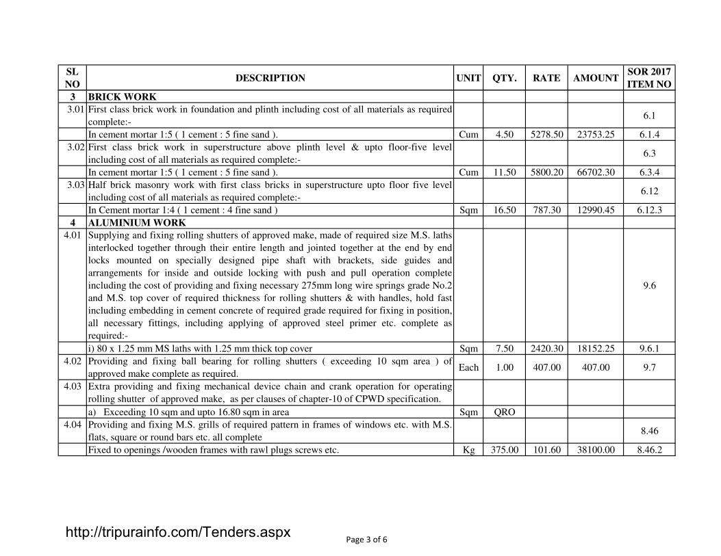
SL
NODESCRIPTION UNIT QTY. RATE AMOUNT
SOR 2017
ITEM NO
3 BRICK WORK
3.01 First class brick work in foundation and plinth including cost of all materials as required
complete:-6.1
In cement mortar 1:5 ( 1 cement : 5 fine sand ). Cum 4.50 5278.50 23753.25 6.1.4
3.02 First class brick work in superstructure above plinth level & upto floor-five level
including cost of all materials as required complete:-6.3
In cement mortar 1:5 ( 1 cement : 5 fine sand ). Cum 11.50 5800.20 66702.30 6.3.4
3.03 Half brick masonry work with first class bricks in superstructure upto floor five level
including cost of all materials as required complete:-6.12
In Cement mortar 1:4 ( 1 cement : 4 fine sand ) Sqm 16.50 787.30 12990.45 6.12.3
4 ALUMINIUM WORK
4.01 Supplying and fixing rolling shutters of approved make, made of required size M.S. laths
interlocked together through their entire length and jointed together at the end by end
locks mounted on specially designed pipe shaft with brackets, side guides and
arrangements for inside and outside locking with push and pull operation complete
including the cost of providing and fixing necessary 275mm long wire springs grade No.2
and M.S. top cover of required thickness for rolling shutters & with handles, hold fast
including embedding in cement concrete of required grade required for fixing in position,
all necessary fittings, including applying of approved steel primer etc. complete as
required:-
9.6
i) 80 x 1.25 mm MS laths with 1.25 mm thick top cover Sqm 7.50 2420.30 18152.25 9.6.1
4.02 Providing and fixing ball bearing for rolling shutters ( exceeding 10 sqm area ) of
approved make complete as required.Each 1.00 407.00 407.00 9.7
4.03 Extra providing and fixing mechanical device chain and crank operation for operating
rolling shutter of approved make, as per clauses of chapter-10 of CPWD specification.
a) Exceeding 10 sqm and upto 16.80 sqm in area Sqm QRO
4.04 Providing and fixing M.S. grills of required pattern in frames of windows etc. with M.S.
flats, square or round bars etc. all complete8.46
Fixed to openings /wooden frames with rawl plugs screws etc. Kg 375.00 101.60 38100.00 8.46.2
Page 3 of 6http://tripurainfo.com/Tenders.aspx

SL
NODESCRIPTION UNIT QTY. RATE AMOUNT
SOR 2017
ITEM NO
Providing and fixing aluminium work for doors, windows, ventilators and partitions with
extruded built up standard tubular sections/ appropriate Z sections and other sections of
approved make conforming to IS:733 and IS : 1285, fixing with dash fasteners of required
dia and size, including necessary filling up of gaps at junctions, i.e. at top, bottom and
sides with required EPDM rubber/neoprene gasket etc. Aluminium sections shall be
smooth, rust free, straight, mitred and jointed mechanically wherever required including
cleat angle, aluminium snap beading for glazing / paneling, C.P. brass / stainless steel
screws, all complete as per architectural drawing and the direction of Engineerincharge.
(Glazing and paneling and dash fasteners to be paid for separately) :-
16.1
For fixed portion of approved quality:- 16.1.1
Powder coated aluminium ( minimum thickness of powder coating of 50 micron ). Kg 250.00 396.80 99200.00 16.1.1.2
4.06 For shutters of doors, windows & ventilators including providing and fixing hinges /
pivots and making provision for fixing fittings wherever required including the cost of
EPDM rubber / neoprene gasket required ( Fittings shall be paid for separately ):-
16.1.2
Powder coated aluminium ( minimum thickness of powder coating of 50 micron ). Sqm 27.00 457.30 12347.10 16.1.2.2
4.07 Providing and fixing glazing of approved quality in aluminium doors, windows,
ventilator, shutters and partition etc. with EPDM rubber / neoprene gasket etc. complete
as per architectural drawing and the direction of Engineer-in-charge (Cost of snap
beading shall be paid in basic item) :-
16.3
a) With glass panes of 4.0 m thickness ( weight not less than 10.0 kg / sqm ) Sqm 27.00 881.40 23797.80 16.3.1
4.08 Providing and fixing factory made UPVC door frame made of UPVC extruded, section
having an overall dimension, as below (tolerance +/- 1mm) with wall thickness 2.0mm+/-
02mm. corners of the door frame to be jointed with galvanized brackets and stainless
screws, joint mitred and plastic wilded. The hinge side vertical of the frames reinforced
by galvanized MS tube of size 19 × 19 mm and 1 mm +/- 0.1 mm wall thickness and 3 nos
stainless steel hinges fixed to the frame complete as per manufacturers specification and
direction of Engineer-In-Charge.
8.114
a) Extruded section Profile size 48x40 mm. Rmt 4.200 246.50 1035.30 8.114.1
Page 4 of 6http://tripurainfo.com/Tenders.aspx

SL
NODESCRIPTION UNIT QTY. RATE AMOUNT
SOR 2017
ITEM NO
4.09 24 mm thick factory made PVC door shutters made of styles and rails of a UPVC hollow
section of size 59x24 mm and wall thickness 2 mm ± 0.2 mm with inbuilt edging on both
sides. The styles and rails mitred and joined at the corners by means of M.S. galvanised
/plastic brackets of size 75×220 mm having wall thickness 1.0 mm and stainless steel
screws. The styles of the shutter reinforced by inserying galvanised MS tube of size
20×20 mm and 1 mm ± 0.1 mm wall thickness. The lock rail made up of "H" Section, a
UPVC hollow section of size 100×24 mm and 2 mm ± 0.2 mm wall thickness fixed to the
shutter styles by means of plastic /galvanised MS "U" cleats. The shutter frame filled with
a UPVC multi-chambered single panel of size not less than 620 mm, having overall
thickness of 20 mm and 1 mm ± 0.1 mm wall thickness. The panels filled vertically and
tie bar at two places by inserting horizontaly 6 mm galvanised MS rod and fastened with
nuts and washers, complete as per manufacturer's specification and direction of Engineer-
In-Charge. (for W.C. and Bathroom door shutter).
Sqm 1.575 1815.60 2859.57 8.115.1
5 FLOORING
5.01 Providing and laying cement concrete 1:2:4 (1 cement: 2 fine sand : 4 graded well burnt
brick aggregate) flooring finished with a floating coat of neat cement including cement
slurry, rounding of edges and strips and cost of glass strips etc. complete.
10.6
40mm thick. Sqm 24.50 439.00 10755.50 10.6.1
6 ROOFING
6.01 Providing and fixing on wall face unplasticised rigid PVC ( working pressure 4 kgf per
sqcm ) rain water pipes conforming to IS : 13592 Type A including jointing with seal ring
conforming to IS : 5382 leaving 10 mm gap for thermal expansion.
11.42
Single socketed pipe -110 mm dia OD RM. 6.50 239.00 1553.50 11.42.2
6.02 Providind 75 mm dia. PVC. Spout set in cement mortar 1 : 3 (1 cement : 3 coarse
sand) complete for all sunsheds.Each 5.00 50.00 250.00
7 FINISHING
7.01 12 mm cement plaster of mix 12.1
In cement mortar 1 : 4 ( 1 cement : 4 fine sand ) Sqm 32.00 150.50 4816.00 12.1.2
7.02 15 mm cement plaster on the rough side of single or half brick wall of mix: 12.2
In cement mortar 1 : 4 ( 1 cement : 4 fine sand ) Sqm 50.00 174.80 8740.00 12.2.2
7.03 20 mm cement plaster of mix : 12.3
Page 5 of 6http://tripurainfo.com/Tenders.aspx

SL
NODESCRIPTION UNIT QTY. RATE AMOUNT
SOR 2017
ITEM NO
In cement mortar 1 : 5 ( 1 cement : 5 fine sand ) Sqm 52.00 197.70 10280.40 12.3.3
7.04 Colour washing such as green, blue or buff with whiting to give an even shade on new
work (two or more coats ) complete.12.22
With a base coat of white washing with lime Sqm 37.50 23.40 877.50 12.22.1
7.05 Finishing walls with water proofing cement paint of required shade of approved brand
and manufacture on new work ( two or more coats applied @ 3.84 kg/10 sqm) complete.
[Payment shall be made after submission of Test Certificate issued by the Manufacturer]
Sqm 61.50 53.30 3277.95 12.28
7.06 Painting with synthetic enamel paint ( two or more coats ) of required colour of approved
brand and manufacture on new work to give an even shade. [Payment shall be made after
submission of Test Certificate issued by the Manufacturer]
Sqm 59.00 73.90 4360.10 12.47
758148.56GRAND TOTAL =
Page 6 of 6http://tripurainfo.com/Tenders.aspx
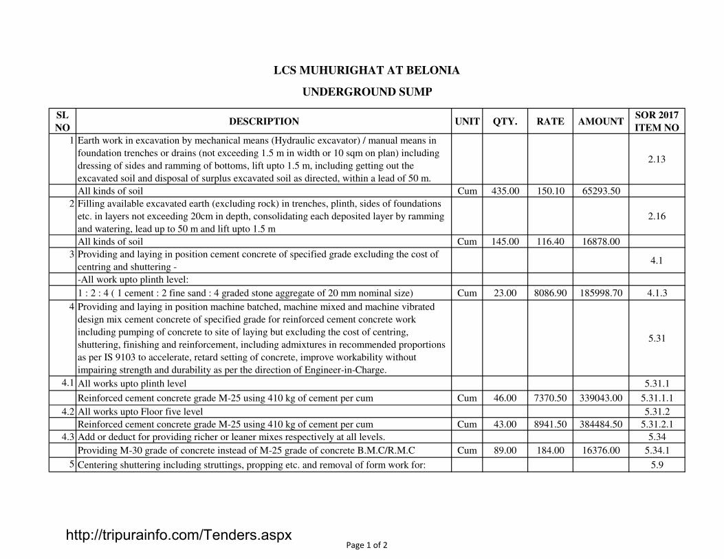
SL
NODESCRIPTION UNIT QTY. RATE AMOUNT
SOR 2017
ITEM NO
1 Earth work in excavation by mechanical means (Hydraulic excavator) / manual means in
foundation trenches or drains (not exceeding 1.5 m in width or 10 sqm on plan) including
dressing of sides and ramming of bottoms, lift upto 1.5 m, including getting out the
excavated soil and disposal of surplus excavated soil as directed, within a lead of 50 m.
2.13
All kinds of soil Cum 435.00 150.10 65293.50
2 Filling available excavated earth (excluding rock) in trenches, plinth, sides of foundations
etc. in layers not exceeding 20cm in depth, consolidating each deposited layer by ramming
and watering, lead up to 50 m and lift upto 1.5 m
2.16
All kinds of soil Cum 145.00 116.40 16878.00
3 Providing and laying in position cement concrete of specified grade excluding the cost of
centring and shuttering -4.1
-All work upto plinth level:
1 : 2 : 4 ( 1 cement : 2 fine sand : 4 graded stone aggregate of 20 mm nominal size) Cum 23.00 8086.90 185998.70 4.1.3
4 Providing and laying in position machine batched, machine mixed and machine vibrated
design mix cement concrete of specified grade for reinforced cement concrete work
including pumping of concrete to site of laying but excluding the cost of centring,
shuttering, finishing and reinforcement, including admixtures in recommended proportions
as per IS 9103 to accelerate, retard setting of concrete, improve workability without
impairing strength and durability as per the direction of Engineer-in-Charge.
5.31
4.1 All works upto plinth level 5.31.1
Reinforced cement concrete grade M-25 using 410 kg of cement per cum Cum 46.00 7370.50 339043.00 5.31.1.1
4.2 All works upto Floor five level 5.31.2
Reinforced cement concrete grade M-25 using 410 kg of cement per cum Cum 43.00 8941.50 384484.50 5.31.2.1
4.3 Add or deduct for providing richer or leaner mixes respectively at all levels. 5.34
Providing M-30 grade of concrete instead of M-25 grade of concrete B.M.C/R.M.C Cum 89.00 184.00 16376.00 5.34.1
5 Centering shuttering including struttings, propping etc. and removal of form work for: 5.9
LCS MUHURIGHAT AT BELONIA
UNDERGROUND SUMP
Page 1 of 2http://tripurainfo.com/Tenders.aspx
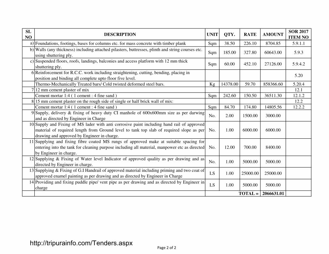
SL
NODESCRIPTION UNIT QTY. RATE AMOUNT
SOR 2017
ITEM NO
a) Foundations, footings, bases for columns etc. for mass concrete with timber plank Sqm 38.50 226.10 8704.85 5.9.1.1
b) Walls (any thickness) including attached pilasters, buttresses, plinth and string courses etc.
using shuttering ply.Sqm 185.00 327.80 60643.00 5.9.3
c) Suspended floors, roofs, landings, balconies and access platform with 12 mm thick
shuttering ply.Sqm 60.00 452.10 27126.00 5.9.4.2
6 Reinforcement for R.C.C. work including straightening, cutting, bending, placing in
position and binding all complete upto floor five level.5.20
Thermo-Mechanically Treated bars/ Cold twisted deformed steel bars. Kg 14378.00 59.70 858366.60 5.20.4
7 12 mm cement plaster of mix 12.1
Cement mortar 1:4 ( 1 cement : 4 fine sand ) Sqm 242.60 150.50 36511.30 12.1.2
8 15 mm cement plaster on the rough side of single or half brick wall of mix: 12.2
Cement mortar 1:4 ( 1 cement : 4 fine sand ) Sqm 84.70 174.80 14805.56 12.2.2
9 Supply, delivery & fixing of heavy duty CI manhole of 600x600mm size as per darwing
and as directed by Engineer in ChargeNo. 2.00 1500.00 3000.00
10 Supply and Fixing of MS lader with anti corrosive paint including hand rail of approved
material of required length from Ground level to tank top slab of required slope as per
drawing and approved by Engineer in charge.
No. 1.00 6000.00 6000.00
11 Supplying and fixing fibre coated MS rungs of approved make at suitable spacing for
entering into the tank for cleaning purpose including all material, manpower etc as directed
by Engineer in charge.
No. 12.00 700.00 8400.00
12 Supplying & Fixing of Water level Indicator of approved quality as per drawing and as
directed by Engineer in charge.No. 1.00 5000.00 5000.00
13 Supplying & Fixing of G.I Handrail of approved material including priming and two coat of
approved enamel painting as per drawing and as directed by Engineer in ChargeLS 1.00 25000.00 25000.00
14 Providing and fixing puddle pipe/ vent pipe as per drawing and as directed by Engineer in
chargeLS 1.00 5000.00 5000.00
2066631.01TOTAL =
Page 2 of 2http://tripurainfo.com/Tenders.aspx

1
TSR 2017
2.13
Cum 550.00 150.10 82555.00
4.1
A A.
a.
Mt 785.00 61.30 48120.50 ii.
2
2.1
A A
a) 63 mm Rmt 42.00 110.50 4641.00 iii
b) 75 mm Rmt 154.00 138.70 21359.80 iv
c) 90 mm Rmt 183.00 166.20 30414.60 v
d) 110 mm Rmt 315.00 238.80 75222.00 vi
e) 140 mm Rmt 21.00 396.50 8326.50 vii
f) 160 mm Rmt 21.00 587.40 8326.50 B i
Earth work in excavation in foundation trenches or drains including dressing of sides and
ramming of bottoms, lift up to 2.0 Mtr. including taking out the excavated soil and
depositing and refilling with watering & ramming and disposal of surplus excavated soil
within the site boundary and the location as approved by Engineer in charge. Complete
etc.
All kinds of soil
Excavating trenches of required width for pipes, cables etc. including exacavation for
sockets, dressing of sides where required, ramming of bottoms, depth upto 1500 mm
including getting out the excavated soil and backfilling of soil as required after laying of
pipeline, in layers not exceeding 200 mm in depth including consolidating each deposited
layer by ramming, watering etc. and disposing of surplus excavated soil with all required
leads as per Chapter - 2 of CPWD specification and direction of the Engineer - in -
charge.
For UPVC pipes in new work
In all kinds of soil
For pipes exceeding 90 mm dia but not exceeding 300 mm dia
Providing, fixing and laying UPVC pipes conforming to IS:4985 jointing with couplers of
same class conforming to IS:10124 (Pt-2) with solvent cement conforming to IS:14182
including testing of joints complete ( but excluding the cost of specials like bend,tees etc.
which will be paid separately) as per CPWD specification and direction of the Engineer-
in-charge.
Class-3 ( working pressure 6.0 kg/cm2
LCS MUHURIGHAT AT BELONIA
WATER DISTRIBUTION NETWORK
SL
NODESCRIPTION UNIT QTY. RATE AMOUNT
DWS 2015
ITEM NO
Page 1 of 8http://tripurainfo.com/Tenders.aspx
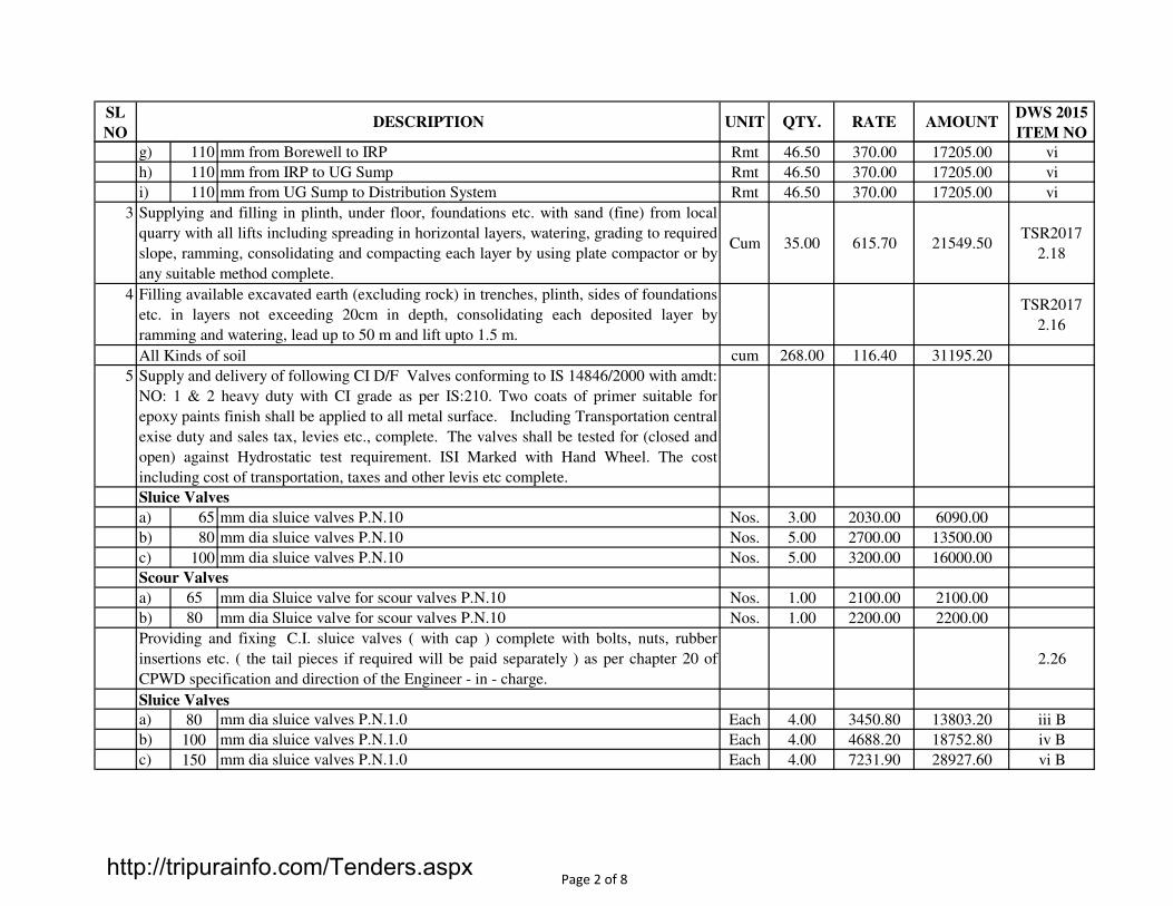
SL
NODESCRIPTION UNIT QTY. RATE AMOUNT
DWS 2015
ITEM NO
g) 110 mm from Borewell to IRP Rmt 46.50 370.00 17205.00 vi
h) 110 mm from IRP to UG Sump Rmt 46.50 370.00 17205.00 vi
i) 110 mm from UG Sump to Distribution System Rmt 46.50 370.00 17205.00 vi
3
Cum 35.00 615.70 21549.50TSR2017
2.18
4TSR2017
2.16
cum 268.00 116.40 31195.20
5
a) 65 mm dia sluice valves P.N.10 Nos. 3.00 2030.00 6090.00
b) 80 mm dia sluice valves P.N.10 Nos. 5.00 2700.00 13500.00
c) 100 mm dia sluice valves P.N.10 Nos. 5.00 3200.00 16000.00
a) 65 mm dia Sluice valve for scour valves P.N.10 Nos. 1.00 2100.00 2100.00
b) 80 mm dia Sluice valve for scour valves P.N.10 Nos. 1.00 2200.00 2200.00
2.26
a) 80 mm dia sluice valves P.N.1.0 Each 4.00 3450.80 13803.20 iii B
b) 100 mm dia sluice valves P.N.1.0 Each 4.00 4688.20 18752.80 iv B
c) 150 mm dia sluice valves P.N.1.0 Each 4.00 7231.90 28927.60 vi B
Sluice Valves
Supplying and filling in plinth, under floor, foundations etc. with sand (fine) from local
quarry with all lifts including spreading in horizontal layers, watering, grading to required
slope, ramming, consolidating and compacting each layer by using plate compactor or by
any suitable method complete.
Filling available excavated earth (excluding rock) in trenches, plinth, sides of foundations
etc. in layers not exceeding 20cm in depth, consolidating each deposited layer by
ramming and watering, lead up to 50 m and lift upto 1.5 m.
All Kinds of soil
Supply and delivery of following CI D/F Valves conforming to IS 14846/2000 with amdt:
NO: 1 & 2 heavy duty with CI grade as per IS:210. Two coats of primer suitable for
epoxy paints finish shall be applied to all metal surface. Including Transportation central
exise duty and sales tax, levies etc., complete. The valves shall be tested for (closed and
open) against Hydrostatic test requirement. ISI Marked with Hand Wheel. The cost
including cost of transportation, taxes and other levis etc complete.
Sluice Valves
Scour Valves
Providing and fixing C.I. sluice valves ( with cap ) complete with bolts, nuts, rubber
insertions etc. ( the tail pieces if required will be paid separately ) as per chapter 20 of
CPWD specification and direction of the Engineer - in - charge.
Page 2 of 8http://tripurainfo.com/Tenders.aspx
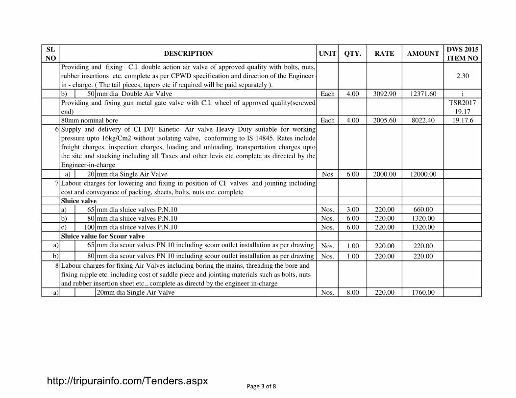
SL
NODESCRIPTION UNIT QTY. RATE AMOUNT
DWS 2015
ITEM NO
2.30
b) 50 mm dia Double Air Valve Each 4.00 3092.90 12371.60 i
TSR2017
19.17
Each 4.00 2005.60 8022.40 19.17.6
6
a) 20 mm dia Single Air Valve Nos 6.00 2000.00 12000.00
7
a) 65 mm dia sluice valves P.N.10 Nos. 3.00 220.00 660.00
b) 80 mm dia sluice valves P.N.10 Nos. 6.00 220.00 1320.00
c) 100 mm dia sluice valves P.N.10 Nos. 6.00 220.00 1320.00
a) 65 mm dia scour valves PN 10 including scour outlet installation as per drawing Nos. 1.00 220.00 220.00
b) 80 mm dia scour valves PN 10 including scour outlet installation as per drawing Nos. 1.00 220.00 220.00
8
a) 20mm dia Single Air Valve Nos. 8.00 220.00 1760.00
Providing and fixing C.I. double action air valve of approved quality with bolts, nuts,
rubber insertions etc. complete as per CPWD specification and direction of the Engineer -
in - charge. ( The tail pieces, tapers etc if required will be paid separately ).
Providing and fixing gun metal gate valve with C.I. wheel of approved quality(screwed
end)
80mm nominal bore
Supply and delivery of CI D/F Kinetic Air valve Heavy Duty suitable for working
pressure upto 16kg/Cm2 without isolating valve, conforming to IS 14845. Rates include
freight charges, inspection charges, loading and unloading, transportation charges upto
the site and stacking including all Taxes and other levis etc complete as directed by the
Engineer-in-charge
Labour charges for lowering and fixing in position of CI valves and jointing including
cost and conveyance of packing, sheets, bolts, nuts etc. complete
Sluice valve
Sluice value for Scour valve
Labour charges for fixing Air Valves including boring the mains, threading the bore and
fixing nipple etc. including cost of saddle piece and jointing materials such as bolts, nuts
and rubber insertion sheet etc., complete as directd by the engineer in-charge
Page 3 of 8http://tripurainfo.com/Tenders.aspx

SL
NODESCRIPTION UNIT QTY. RATE AMOUNT
DWS 2015
ITEM NO
9
Nos. 23.00 8500.00 195500.00
10
Nos. 2.00 14000.00 28000.00
11 2.10
Mtr. R.O. 984.70 x
Mtr. R.O. 781.60 ix
Mtr. R.O. 565.80 viii
Mtr. R.O. 430.40 vii
Mtr. R.O. 390.20 vi
Mtr. R.O. 341.40 v
Mtr. R.O. 300.50 iv
Mtr. R.O. 247.30 iii
Mtr. R.O. 186.40 ii
80mm dia
65mm dia
50 mm dia
40 mm dia
32 mm dia
25 mm dia
Constructing brick masonry chamber for underground inspection chamber and bends with
1st class bricks in cement mortar 1 : 5 ( 1 cement : 5 fine sand) C.I. cover with frame (
light duty ) ( 455 x 610 ) mm internal dimensions total weight of cover with frame to be
not less than 38 kg ( weight of cover 23 kg and weight of frame 15 kg ) R.C.C. top slab
with 1 : 2 : 4 mix ( 1 cement : 2 fine sand : 4 graded well burnt brick aggregate 20 mm
nominal size ) including reinforcement and formwork as required, foundation concrete 1 :
5 : 10 ( 1 cement : 5 fine sand : 10 graded well burnt brick aggregate 40 mm nominal size
) inside plastering 12mm thick with cement mortar 1 : 3 ( 1 cement : 3 fine sand ) finished
smooth with a floating coat of neat cement on walls and bed concrete etc. complete as per
standard design as per clauses of Chapter - 21 of CPWD specification.
Inside dimensions 455 mm x 610 mm and 1000 mm deep for single pipeline
Supply, delivery and fixing to the industrial units including fixing water meter
(Domestic), isolation valves, water meter protection chamber etc and connection from
mainline to individual unit upto a length of 5mt. The quoted rate should include all
material and labour etc complete.
25mm dia
Providing and fixing G.I. pipes complete with G.I. fittings including trenching,
dewatering and refilling etc.
External work
125 mm dia
100 mm dia
20 mm dia
Page 4 of 8http://tripurainfo.com/Tenders.aspx
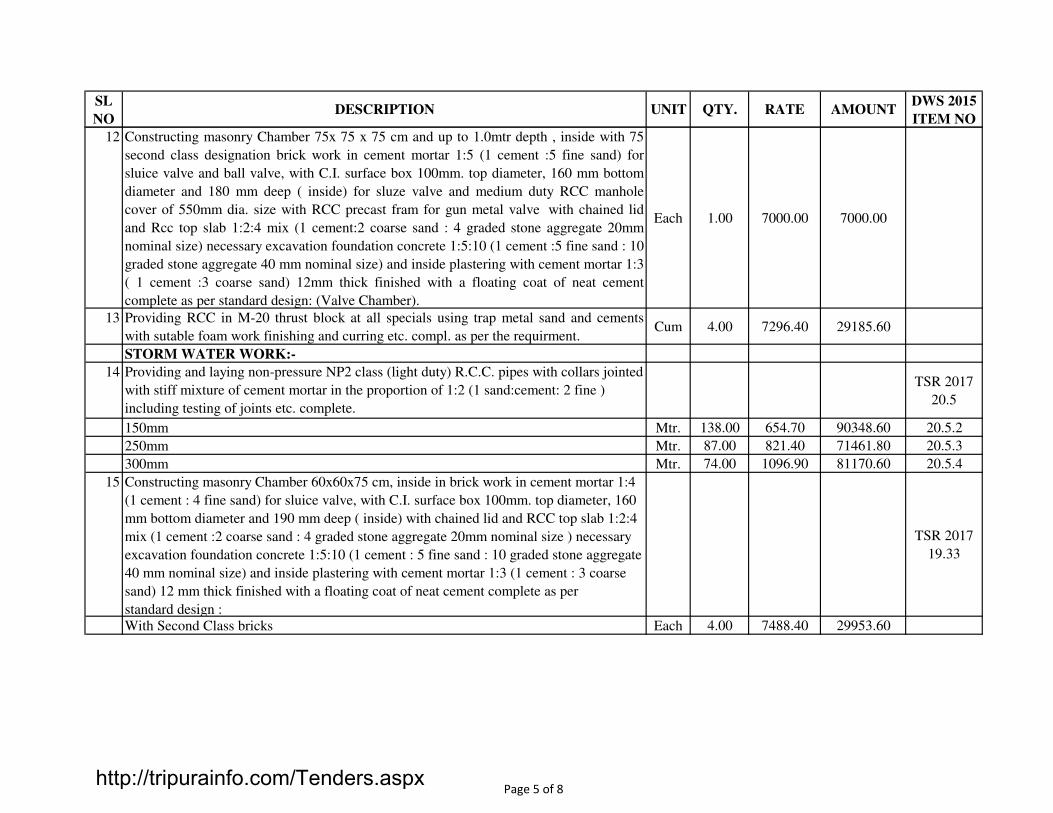
SL
NODESCRIPTION UNIT QTY. RATE AMOUNT
DWS 2015
ITEM NO
12
Each 1.00 7000.00 7000.00
13Cum 4.00 7296.40 29185.60
14TSR 2017
20.5
Mtr. 138.00 654.70 90348.60 20.5.2
Mtr. 87.00 821.40 71461.80 20.5.3
Mtr. 74.00 1096.90 81170.60 20.5.4
15
TSR 2017
19.33
Each 4.00 7488.40 29953.60
Providing RCC in M-20 thrust block at all specials using trap metal sand and cements
with sutable foam work finishing and curring etc. compl. as per the requirment.
Constructing masonry Chamber 75x 75 x 75 cm and up to 1.0mtr depth , inside with 75
second class designation brick work in cement mortar 1:5 (1 cement :5 fine sand) for
sluice valve and ball valve, with C.I. surface box 100mm. top diameter, 160 mm bottom
diameter and 180 mm deep ( inside) for sluze valve and medium duty RCC manhole
cover of 550mm dia. size with RCC precast fram for gun metal valve with chained lid
and Rcc top slab 1:2:4 mix (1 cement:2 coarse sand : 4 graded stone aggregate 20mm
nominal size) necessary excavation foundation concrete 1:5:10 (1 cement :5 fine sand : 10
graded stone aggregate 40 mm nominal size) and inside plastering with cement mortar 1:3
( 1 cement :3 coarse sand) 12mm thick finished with a floating coat of neat cement
complete as per standard design: (Valve Chamber).
150mm
250mm
300mm
Providing and laying non-pressure NP2 class (light duty) R.C.C. pipes with collars jointed
with stiff mixture of cement mortar in the proportion of 1:2 (1 sand:cement: 2 fine )
including testing of joints etc. complete.
Constructing masonry Chamber 60x60x75 cm, inside in brick work in cement mortar 1:4
(1 cement : 4 fine sand) for sluice valve, with C.I. surface box 100mm. top diameter, 160
mm bottom diameter and 190 mm deep ( inside) with chained lid and RCC top slab 1:2:4
mix (1 cement :2 coarse sand : 4 graded stone aggregate 20mm nominal size ) necessary
excavation foundation concrete 1:5:10 (1 cement : 5 fine sand : 10 graded stone aggregate
40 mm nominal size) and inside plastering with cement mortar 1:3 (1 cement : 3 coarse
sand) 12 mm thick finished with a floating coat of neat cement complete as per
standard design :
With Second Class bricks
STORM WATER WORK:-
Page 5 of 8http://tripurainfo.com/Tenders.aspx
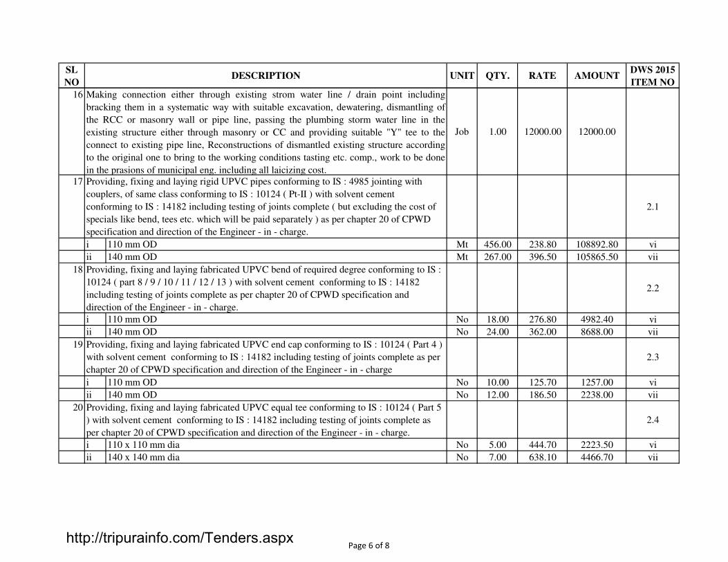
SL
NODESCRIPTION UNIT QTY. RATE AMOUNT
DWS 2015
ITEM NO
16
Job 1.00 12000.00 12000.00
17
2.1
i Mt 456.00 238.80 108892.80 vi
ii Mt 267.00 396.50 105865.50 vii
18
2.2
i No 18.00 276.80 4982.40 vi
ii No 24.00 362.00 8688.00 vii
19
2.3
i No 10.00 125.70 1257.00 vi
ii No 12.00 186.50 2238.00 vii
20
2.4
i No 5.00 444.70 2223.50 vi
ii No 7.00 638.10 4466.70 vii
Making connection either through existing strom water line / drain point including
bracking them in a systematic way with suitable excavation, dewatering, dismantling of
the RCC or masonry wall or pipe line, passing the plumbing storm water line in the
existing structure either through masonry or CC and providing suitable "Y" tee to the
connect to existing pipe line, Reconstructions of dismantled existing structure according
to the original one to bring to the working conditions tasting etc. comp., work to be done
in the prasions of municipal eng. including all laicizing cost.
Providing, fixing and laying rigid UPVC pipes conforming to IS : 4985 jointing with
couplers, of same class conforming to IS : 10124 ( Pt-II ) with solvent cement
conforming to IS : 14182 including testing of joints complete ( but excluding the cost of
specials like bend, tees etc. which will be paid separately ) as per chapter 20 of CPWD
specification and direction of the Engineer - in - charge.
Providing, fixing and laying fabricated UPVC bend of required degree conforming to IS :
10124 ( part 8 / 9 / 10 / 11 / 12 / 13 ) with solvent cement conforming to IS : 14182
including testing of joints complete as per chapter 20 of CPWD specification and
direction of the Engineer - in - charge.
110 mm OD
Providing, fixing and laying fabricated UPVC end cap conforming to IS : 10124 ( Part 4 )
with solvent cement conforming to IS : 14182 including testing of joints complete as per
chapter 20 of CPWD specification and direction of the Engineer - in - charge
Providing, fixing and laying fabricated UPVC equal tee conforming to IS : 10124 ( Part 5
) with solvent cement conforming to IS : 14182 including testing of joints complete as
per chapter 20 of CPWD specification and direction of the Engineer - in - charge.
110 x 110 mm dia
140 x 140 mm dia
140 mm OD
110 mm OD
140 mm OD
110 mm OD
140 mm OD
Page 6 of 8http://tripurainfo.com/Tenders.aspx

SL
NODESCRIPTION UNIT QTY. RATE AMOUNT
DWS 2015
ITEM NO
21
2.26
i v
A No 4.00 6091.80 24367.20 A
B PN - 1.0 No 6.00 6113.80 36682.80 B
ii vi
A No 3.00 7354.00 22062.00 A
B No 4.00 7231.90 28927.60 B
22
TSR 2017
19.32
No 5.00 1621.60 8108.00 19.32.1
23
TSR 2017
19.34
No 2.00 12647.30 25294.60 19.34.1
24
2.30
Providing and fixing C.I. double action air valve of approved quality with bolts, nuts,
rubber insertions etc. complete as per chapter 20 of CPWD specification and direction of
the Engineer - in - charge. ( The tail pieces, tapers etc if required will be paid separately ).
PN - 1.6
PN - 1.0
With 2nd class bricks.
With 1st class bricks.
Constructing masonry Chamber 90 x 90 x 100 cm, inside with brick work in cement
mortar 1 : 4 ( 1 cement : 4 fine sand ) for sluice valve, with C.I. surface box 100 mm top
diameter, 160 mm bottom diameter and 180 mm deep ( inside ) with chained lid and RCC
top slab 1 : 2 : 4 mix ( 1 cement : 2 fine sand : 4 graded stone aggregate 20 mm
nominal size ) necessary excavation foundation concrete 1 : 5 : 10 ( 1 cement : 5 fine sand
: 10 graded stone aggregate 40 mm nominal size ) and inside plastering with cement
mortar 1 : 3 ( 1 cement : 3 fine sand ) 12 mm thick finished with a floating coat of neat
cement complete as per standard design, CPWD specification and direction of the
Engineer - in - charge.
Providing and fixing C.I. sluice valves ( with cap ) complete with bolts, nuts, rubber
insertions etc. ( the tail pieces if required will be paid separately ) as per chapter 20 of
CPWD specification and direction of the Engineer - in - charge.
Constructing masonry Chamber 300 x 300 x 500 mm, inside with brick work in cement
mortar 1:4 ( 1 cement: 4 fine sand ) for stop cock, with C. I. surface box 100 x 100 x 75
mm ( inside ) with hinged cover fixed in cement concrete slab 1:2:4 mix ( 1 cement: 2
fine sand : 4 graded stone aggregate 20 mm nominal size ) necessary excavation including
refilling as necessary, foundation concrete 1:5:10 ( 1 cement : 5 fine sand : 10 graded
stone aggregate 40 mm nominal size ) and inside plastering with cement mortar 1:3 ( 1
cement : 3 fine sand ) 12 mm thick finished with a floating coat of neat cement complete
as per standard design ,
125 mm dia
PN - 1.6
150 mm dia
Page 7 of 8http://tripurainfo.com/Tenders.aspx
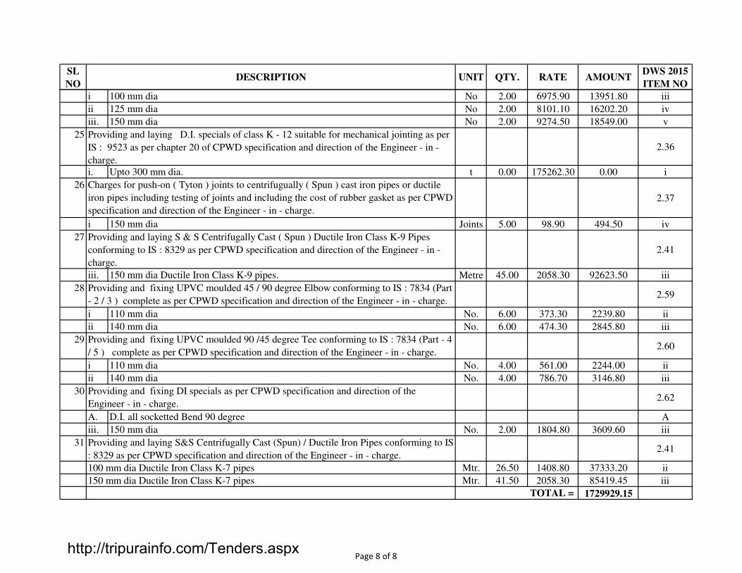
SL
NODESCRIPTION UNIT QTY. RATE AMOUNT
DWS 2015
ITEM NO
i No 2.00 6975.90 13951.80 iii
ii No 2.00 8101.10 16202.20 iv
iii. No 2.00 9274.50 18549.00 v
25
2.36
i. t 0.00 175262.30 0.00 i
26
2.37
i Joints 5.00 98.90 494.50 iv
27
2.41
iii. Metre 45.00 2058.30 92623.50 iii
282.59
i No. 6.00 373.30 2239.80 ii
ii No. 6.00 474.30 2845.80 iii
292.60
i No. 4.00 561.00 2244.00 ii
ii No. 4.00 786.70 3146.80 iii
302.62
A. A
iii. No. 2.00 1804.80 3609.60 iii
312.41
Mtr. 26.50 1408.80 37333.20 ii
Mtr. 41.50 2058.30 85419.45 iii
1729929.15
125 mm dia
150 mm dia
Upto 300 mm dia.
Providing and laying D.I. specials of class K - 12 suitable for mechanical jointing as per
IS : 9523 as per chapter 20 of CPWD specification and direction of the Engineer - in -
charge.
100 mm dia Ductile Iron Class K-7 pipes
150 mm dia Ductile Iron Class K-7 pipes
TOTAL =
150 mm dia
Providing and laying S&S Centrifugally Cast (Spun) / Ductile Iron Pipes conforming to IS
: 8329 as per CPWD specification and direction of the Engineer - in - charge.
Charges for push-on ( Tyton ) joints to centrifugually ( Spun ) cast iron pipes or ductile
iron pipes including testing of joints and including the cost of rubber gasket as per CPWD
specification and direction of the Engineer - in - charge.
Providing and laying S & S Centrifugally Cast ( Spun ) Ductile Iron Class K-9 Pipes
conforming to IS : 8329 as per CPWD specification and direction of the Engineer - in -
charge.
Providing and fixing UPVC moulded 45 / 90 degree Elbow conforming to IS : 7834 (Part
- 2 / 3 ) complete as per CPWD specification and direction of the Engineer - in - charge.
Providing and fixing UPVC moulded 90 /45 degree Tee conforming to IS : 7834 (Part - 4
/ 5 ) complete as per CPWD specification and direction of the Engineer - in - charge.
Providing and fixing DI specials as per CPWD specification and direction of the
Engineer - in - charge.
150 mm dia Ductile Iron Class K-9 pipes.
110 mm dia
140 mm dia
110 mm dia
140 mm dia
D.I. all socketted Bend 90 degree
150 mm dia
100 mm dia
Page 8 of 8http://tripurainfo.com/Tenders.aspx

SL NO DESCRIPTION UNIT QUANTITY RATE AMOUNT
1 Supply, delivery and fixing of Submersible pumps of 5 HP in bore wells
including all specials for inlet and outlet to bore wells etc, installing and
Erection of Pumps with all electrical, plumbing and Mechanical Items.Nos 1.00 25000.00 25000.00
25000.00
LCS MUHURIGHAT AT BELONIA
TOTAL =
PUMP HOUSE
http://tripurainfo.com/Tenders.aspx

TRIPURA INDUSTRIAL DEVELOPMENT CORPORATION LIMITED
Name of work :- Extension of 3 phase, 4 wire under ground line from sub-station, supplying, installation of feeder pillars, LED Lights
fitting, brackets etc. for providing of street lights in LCS Muhurighat, Belonia.
Sl. No. Description of supply/ works Unit Qty. Rate in Rs. Amount in Rs. Remarks
1 2 3 4 5 6 7
1. Laying of one number PVC insulated and PVC sheathed / XLPE
power cable of 1.1 KV grade of following size direct in ground
including excavation, sand cushioning, protective covering and
refilling the trench etc. as required.
a) Upto 35 sqmm. Meter 2000 167.00 334000.00 DSR-2012
b) Upto 95 sqmm. -do- 500 173.00 86500.00 -do-
2. Supplying and embedding following dia G.I. pipe (medium
class) in pole collar/foundation (during casting)for cable entry
including bending the pipe to the required shape complete as
required.
-do-
a) 40 mm dia -do- 600 274.00 1,64,400.00 -do-
3. Supplying and making indoor end termination with brass
compression gland and aluminium lugs for following size of PVC
insulated and PVC sheathed /XLPE aluminium conductor cable
of 1.1kv grade as required.
No 400 262.00 1,04,800.00 -do-
4. Earthing with G.I.earth pipe 4.5 metre long, 40mm dia including
accessories and providing masonry enclosure with cover plate
having locking arrangement and watering pipe etc. with
charcoat/ coke and salt as required.
Set 3 3385.00 10,155.00 -do-
5. Supplying of 650/1100 volts XLPE insulated aluminium
conductor cable armoured/Un-armoured
a) 4C, 16 sqmm. (Armoured) Meter 1500 316.00 474000.00 Analysis Rate
b) 3.5C, 50 sqmm. (Armoured) -do- 500 664.00 332000.00 -do-
c) 3.5C, 70 sqmm. (Armoured) -do- 60 863.00 51,780.00 -do-
6. Supplying of 650/1100volts XLPE insulated copper conductor
cable unarmoured 3 core, 4 sqmm cable.
-do- 1000 231.00 231000.00 -do-
Contd....P/2.
P/2.
http://tripurainfo.com/Tenders.aspx

1 2 3 4 5 6 7
7. Supplying and fixing with existing pole bracket, testing and
commissioning 45 watt LED Street light fitting with lamps, driver
and all accessories including necessary connection as required
with clamps for fixing the wires and pipe with existing ST/PCC
poles but excluding the cost of connecting cable
No 80 9980.00 798400.00
8. Supplying and fixing with existing pole bracket, testing and
commissioning 45 watt LED Street light fitting with lamps, driver
and all accessories including necessary connection as required
with clamps for fixing the wires and pipe with existing ST/PCC
poles but excluding the cost of connecting cable
No 20 22,173.00 443460.00
9. Supplying and fixing of sintex equivalent junction box of 300 x
200 x 105 mm with 8 way connector &2 Nos. 6 A DP MCB (b)
supplying and laying of 3 Nos. 38 mm dia. PVC pipe suitable for
XLPE cable entry and exit to junction box as required with
necessary civil work for grouting of ST/PCC pole
(600x600x600mm)i/c excavation and back filling, earthing etc.
as required
No
80
3100.00
248000.00
10. Feeder pillar No 1 49,276.00 49276.00
11. Supplying and fixing of street light bracket with two pairs MS
clamps for fixing of LED light fixture made of 40mm dia, 3mtrs.
Long G.I. pipe i/c supplying MS clamps, nuts, bolts, washers etc.
as required.
No 80 1,655.00 132400.00
Grand Total 3460171.00
http://tripurainfo.com/Tenders.aspx

TRIPURA INDUSTRIAL DEVELOPMENT CORPORATION LIMITTED (TIDCL)
Name of work :- Installation of 1 no 500 KVA,11/0433 KV Sub-station at LCS Muhurighat, Belonia, Tripura.
Sl. No. Description Unit Quantity Rate in Rs. Amount in Rs Remark
1. Supplying of :- Outdoor type 500 KVA,11/0.433-0.250,
“ONAN” type transformer. Standard = (a) system voltage –
12 KV, (b) Rated voltage (HV) 11 kv, (c) Rated voltage
(LV))0.433-0.250, (d) Phase- 3 phase, (e) Frequency – 50HZ
subjected to fluctuation of + -5 % (f) Rated short circuit
level- 13.1KV Fw 3 sec at 11 Kv, (g) Vector group- Dyn-11.
The transformer materials shall confirming in all respect to
the relevant Indian/ International standard specification
with all latest amendments thereof.
No 1 579507.00 579507.00
2. 11 kv, 200 amps, single brake G.O.S(one set of 3 units) Set 1 7899.00 7899.00 -do-
3. 12 kv, D.O. fuse unit with fuse carrier system (one set of 3
units)
Set 1 5221.00 5221.00 -do-
4. 11 kv lightning arrester. No 3 369.00 1107.00 -do-
5. 11 kv, 45 KM Disc isolator (ball & socket type) No 3 240.60 722.00 -do-
6. Fittings for 11 kv, 45 kn Dise isolator (ball & socket type) No 6 349.58 2097.00 -do-
7. 11 kv pin isolator No 6 52.98 318.00 -do-
8. G.I. pin for 11 kv pin isolator No 6 82.48 495.00 -do-
9. 75x40x6mm M.S. channel Kg. 52 54.73 2846.00 -do-
10. 65x65x6mm M.S. angle Kg. 38 54.73 2080.00 -do-
11. M.S. clamp for fixing of cross arm made of 50x6mm M.S.
flat
No 12 70.00 840.00 -do-
12. 11mtrs. Long S.T. pole No 2 13582.65 27165.00 -do-
13. Stay set complete with straining screw, stay isolater, stay
road, stay plate etc.
Set 2 828.98 1658.00 -do-
14. Nuts and bolts 16 mm dia, 90 mm long Kg. 5 68.71 344.00 -do-
15. 1.1kv , 240sq mm pvc isolater and pvc sheathed aluminium
conductor cable
Mtr. 75 192.95 14471.00 -do-
16. 1.1kv, 70 sqmm pvc isolated and pvc sheathed aluminium
conductor cable
Mtr. 30 65.62 1969.00 -do-
Contd...P/2
http://tripurainfo.com/Tenders.aspx

Page/2.
Sl. No. Description Unit Quantity Rate in Rs. Amount in Rs Remark
17. G.I standard wire 7/2.5mm Kg. 10 81.37 814.00 Rate approved
by TIDC
Sub-total(A) 649563.00
18. Earthing with G.I. pipe 4.5 mtrs long, 40 mm dia. Including
accessories, and providing masonry enclosure with cover
plate having locking arrangement and watering pipe etc.
with charcoal and salt as required.
Set 4 3385 13540.00 -do-
19. Supplying, insulation, testing & commissioning of free
standing, floor mounted out door type, air insulated, totely
enclosed vermin proof dead front, compartmentalized,
cubicle type, 2mm thick sheet steel enclosure panel
suitable for use on 415 v, 3 phase,4 wire, 50 hz A.C.
system, including circuit breaker/ S.F. unit, high
conductivity TP & N Aluminium bus-bars, risers, extended
bush-bars for cable connections, outgoing circuits breakers
instrument panel, CTs outgoing feeder terminals and
incoming cable compartment. The incoming and outgoing
functional units shall be arranged in multi tier formation to
provide a complete with switches & circuit breakers of
following ratings, interconnections, G.I. earth bus bar of
adequate size covering the entire kength of switch board
with drilled holes, G.I. bolts, nuts, washers, etc. The cubicle
should be painted with two (2) Coats of synthetic paint
over two(2) coats of zinc chromateprimer. The complete
fabricated construction shall be done as per detailed
specification and conforming to relevant name plate of
panels, danger board, incoming and outgoing feeders with
ampere rating of switches/MCCBs/MCBs are to be fixed fix
up on front doors above or below respectives switches.
Approval of manufacturers drawings from consultants
/employers is required before commencing manufacture
and panel should tested in presence of
consultants/employers engineer at manufacturers
premises before dispatch to the site including base.
No 1 435413.00 435413.00 -do-
Contd...P/3
http://tripurainfo.com/Tenders.aspx

Page/3.
Sl. No. Description Unit Quantity Rate in Rs. Amount in Rs Remark
Main Power Panel
Incoming : 415 v, 800A, 36 KA, 4 pole MCCB (Relay range
320-400 (A) – 1 No.
Multification metre with selector switches to observe
current and voltage, energy PF etc. with set of 400/1A CTs
as required.
3 Nos phase indication lamps (RYB)
3 Nos of Protective fuses.
SLEEVED TPN ALUMINIUM BUS BARS :-
(1) 100 mm x 10 mm for phases.
(2) 50 mm x 6 mm for neutral.
G.I. Earth bus-bar
25 mm x6 mm covering the length of the panel.
OUT GOING :-
415 V, 250 A, 36 KA, 4 pole MCCBs with relay range 200-
250A-4 nos ( L&T/ LEGRAND make ).
415 volt, 100A, 25KA, 4 Pole MCCB with realy range 80-
100A-2 nos ( L&T/ LEGRAND make ).
Multifunctional digital weather proof time switch Astorex –
D-22- 1 no (LEGRANDE or equivalent make)
Sub-total(B) 1098516.00
Adding 35 % for erection testing &
commissioning on Sub-Total(A)
227348.00
Grand Total 13,25,864.00
Rupees Thirteen Lac twenty five thousand eight hundred sixty four only.
http://tripurainfo.com/Tenders.aspx
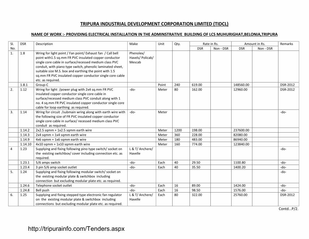
TRIPURA INDUSTRIAL DEVELOPMENT CORPORATION LIMITED (TIDCL)
NAME OF WORK :- PROVIDING ELECTRICAL INSTALLATION IN THE ADMINSTRATIVE BUILDING OF LCS MUHURIGHAT,BELONIA,TRIPURA
Sl.
No.
DSR Description Make Unit Qty. Rate in Rs. Amount in Rs. Remarks
DSR Non - DSR DSR Non - DSR
1. 1.8 Wring for light point / Fan point/ Exhaust fan / Call bell
point with1.5 sq.mm FR PVC insulated copper conductor
single core cable in surface/recessed medium class PVC
conduit, with piano type switch, phenolic laminated sheet,
suitable size M.S. box and earthing the point with 1.5
sq.mm FR PVC insulated copper conductor single core cable
etc. as required.
Phenolex/
Havels/ Policab/
Mescab
1.8.1 Group-C Point 240 619.00 148560.00 DSR-2012
2. 1.12 Wring for light /power plug with 2x4 sq.mm FR PVC
insulated copper conductor single core cable in
surface/recessed medium class PVC conduit along with 1
no. 4 sq.mm FR PVC insulated copper conductor single core
cable for loop earthing as required.
-do- Meter 80 162.00 12960.00 DSR-2012
3. 1.14 Wring for circuit /submain wring along with earth wire with
the following size of FR PVC insulated copper conductor
single core cable in surface/ recessed medium class PVC
conduit as required.
-do- Meter -do-
1.14.2 2x2.5 sqmm + 1x2.5 sqmm earth wire Meter 1200 198.00 237600.00
1.14.3 2x4 sqmm + 1x4 sqmm earth wire Meter 360 228.00 82080.00
1.14.9 4x6 sqmm + 1x6 sqmm earth wire Meter 180 483.00 86940.00
1.14.10 4x10 sqmm + 1x10 sqmm earth wire Meter 160 774.00 123840.00
4 1.23 Supplying and fixing following pino type switch/ socket on
the existing switchbox/ cover including connection etc. as
required.
L & T/ Anchere/
Havelle
-do-
1.23.1 5/6 amps switch -do- Each 40 29.50 1100.80 -do-
1.23.4 3 pin 5/6 amp socket outlet -do- Each 40 35.50 1400.20 -do-
5. 1.24 Supplying and fixing following modular switch/ socket on
the existing modular plate & switchbox including
connection but excluding modular plate etc. as required.
-do-
1.24.6 Telephone socket outlet -do- Each 16 89.00 1424.00 -do-
1.24.8 Bell push -do- Each 16 98.50 1576.00 -do-
6. 1.25 Supplying and fixing stepped type electronic fan regulator
on the existing modular plate & switchbox including
connections but excluding modular plate etc. as required.
L & T/ Anchere/
Havelle
Each 80 322.00 25760.00 DSR-2012
Contd...P/2.
http://tripurainfo.com/Tenders.aspx

Page/2.
Sl.
No.
DSR Description Make Unit Qty. Rate in Rs. Amount in Rs. Remarks
DSR Non - DSR DSR Non - DSR
7. 1.22 Supplying and fixing metal box of following sizes(nominal
size) on surface or recess with suitable sizeof phenolic
laminated sheet cover in front including painting etc. as
required.
-do-
1.22.1 75 mm x 75mm x60mm deep Each 160 72.00 11520.00 DSR-2012
1.22.5 180mm x 100 mm x 60mm deep Each 80 108.00 8640.00
1.22.12 200mm x 250mm x 100 mm deep Each 40 239.00 9560.00
1.22.16 250mm x 300mm x 100 mmdeep Each 24 310.00 4440.00
8. 1.30 Supplying and fixing metal box of 180mm x 100 mm x 60
mm deep (normal size) on surface or in recess with suitable
size of phenolic laminated sheet cover in front including
providing and fixing 6 pin and 15/16 amps socket
outlet and 15/16 amps pino type switch, connection,
painting etc. as required.
Each 16 225.00 3600.00
9. 1.33 Supplying and fixing 3 pin,5 amps celling rose on theexisting
junction box / wooden blok including connection etc. as
required.
Each 160 34.00 5440.00
10. 1.34 Supplying and fixing brass batten/ angle holder including
connection etc. as required.
Each 40 63.00 2520.00
11. 1.38 Supplying and fixing call bell/ buzzer suitable for single
phase 230 volts, complete as required.
Approved make Each 16 54.00 864.00
12. 1.41 Installation, testing and commissioning of pre-wired,
fluorescent fitting/ compect fluorescent fitting of all types,
with all accessories and tube etc. directly oncelling/ wall,
including connection with 1.5 sq mm FR PVC insulated,
copper conductor, single core cable and earthing etc. as
required.
-do- Each 80 69.5 5560.00
13. 1.42 Installation, testing and commissioning of pre-wired,
fluorescent fitting/ compect fluorescent fitting of all types,
with all accessories and tube etc.including supply and fixing
ball and socket arrangement 2 no. Down rods of 20mm diax
1.6mm thick stell conduit up to 30cm length,painting and
wiring the down roads and connection with 1.5 sq mm FR
PVC insulated, copper conductor, single core cable and
earthing etc. as required.
Approved make Each 80 195 15600.00 DSR-2012
Contd...P/3.
http://tripurainfo.com/Tenders.aspx

Page/3.
Sl.
No.
DSR Description Make Unit Qty. Rate in Rs. Amount in Rs. Remarks
DSR Non - DSR DSR Non - DSR
14. 1.44 Installation, testing and commissioning of ceiling Fan ,
including wiring the down rods of standard length (upto
30cm) with 1.5 sq mm FR PVC insulated, copper conductor,
single core cable and earthing etc. as required.
Each 50 1300 65000.00 -do-
15. 1.45 Installation, testing and commissioning of ceiling Fan ,
including wiring the down rods of standard length (upto
30cm) with 1.5 sq mm FR PVC insulated, copper conductor,
single core cable including providing and fixing phenolic
laminated sheet cover on the fan box etc. as required.
Each 20 2400 48000.00 -do-
16. 1.50 Installation exhaust fan in the existing opening, including
making good the damage, connection,
testing,commissioning etc. as required.
-do-
1.50.1 Upto 450 mm sweep Each 16 163.00 2608.00
17. 1.51 Extra for fixing thelouvers / shutters complete with frame
for a exhaust fan of all sizes.
Each 16 68.50 1096.00 -do-
18. 2.2 Providing and fixing following rating and breaking capacity
TPK MCCB in existing cubicle panel board including drilling
holes in cubicle panel making connections etc. as required.
L & T Legrand -do-
2.2.1 100 Amp 16 / KA Each 4 2801.00 11204.00
19. 2.4 Supplying and fixing following way, horizontal type three
pole and neutral, sheet, MCB distribution board, 415 volts,
on surface/ recess, complete with tinned copper bus bar,
netural bus bar, earth bar, din bsr, interconnections,
powder painted including earthing etc. as required ( But
without MCB/RCCB/Isolator)
-do- -do-
2.4.4 4 way ( 4 + 12 ), double door Each 8 1654.00 13232.00
20. 2.10 Supplying and fixing 5 amps to 32 amps rating, 240/415
volts, “C” curve, mainiature circuit breker suitable for
inductive load offollowing poles in the existing MCB DB
complete with connections, testing and commissioning
etc.as required.
L & T Legrand DSR-2012
2.10.1 Single pole Each 96 141.00 13536.00
21. 2.13 Supplying and fixing following rating four pole 415 volts,
isolator in the existing MCB DB complete with connections,
testing and commissioning etc. as required.
Any approved
make
http://tripurainfo.com/Tenders.aspx

2.13.1 40 amps Each 4 554.00 2216.00
2.13.2 63 amps -do- 4 563.00 2252
Contd...P/4.
Page/4.
Sl.
No.
DSR Description Make Unit Qty. Rate in Rs. Amount in Rs. Remarks
DSR Non - DSR DSR Non – DSR
22. 2.18 Supplying and fixing 20 amps 240 volts, TPN industrial
type, socket outlet, with 2 pole and earth, metal
enclosed plug top along woth 20 amps “C” curve, SP,
MCB, in sheet steel enclosure, on surface or in recess,
with chained metal cover for the socket out let
complete with connections, testing and commissioning
etc.as required.
L & T Legrand -do- 16 693.00 11088.00 -do-
23. 2.21 Providing and fixing MV. Danger notice plate of 200 mm
x 150 mm, made of mild steel, at least 2mm thick and
vitreous enameled white on both sides and with
inscription in single red colour onfront side as required.
Any approved
make
-do- 4 121.00 484.00 -do-
24. 5.2 Earthing with G.I. earth pipe 4.5 metre long, 40mm dia
including accessories and providing masonry enclosure
with cover plate having locking arrangement and
watering pipe etc. with charcoal/coke and salt as
required.
TATA/ Zindal -do- 8 3385.00 27080.00 -do-
25. 5.9 Supplying and laying 25mm x 5mm G.I. strip at 0.50
meter below ground as strips earthelectrode, including
connection/ terminatingwith G.I. nut, bolt, spring,
washer etc. as required ( jointing shall be done by
overlapping and with 2 sets of G.I. nut bolt & spring
washer spaced at50mm )
TISCO/ ISCO/
SAIL
-do- 80 97.50 7800 -do-
26. 7.1 Laying of one number PVC insulated and PVC sheated / x
LPE power cable of 1.1kv grade of following size direct in
ground includingexcavation,sand cushionin, protective
covering and refilling thetrench etc.as required.
Gloster/ Neeco/
Havels
DSR-2012
7.1.1 Upto 35sq. mm Metre 240 177.00 42480.00
27. Non
shedule
Supply of 4 core, 1.1kv grade 16 amps xLPE Aluminium
conductor cable.
-do- 240 234.00 56160.00 Market
price
28. -d0- Supply and fixingnof G.I. pipe with S.T. Pole and other
point by necessary clamps , nuts &bolts etc. as required
(Medium)
TATA/ ZINDAL -do- 32.22 151.30 5026.00 -do-
http://tripurainfo.com/Tenders.aspx

29. -do- Supply of 1400 mm sweep A.C ceiling Fan CGL/Havels/
Bajaj
Each 80 2000.00 1,60,000.00 -do-
30. - Non
shedule
do-
Supply of Exhaust Fan 300 mm sweep including making
arrangement for hole etc. (Excluding fitting & fixing )
CGL or its
equivalent
-do- 16 2675 42800.00 -do-
Contd...P/5.
Page/5.
Sl.
No.
DSR Description Make Unit Qty. Rate in Rs. Amount in Rs. Remarks
DSR Non - DSR DSR Non – DSR
31. -do- Supplying of decorative compact energy efficiant
luminarie with CRCT body and replaceable electronics
balast 1x 28 wall TSFTL code No. LHDTOU28039 of
Havells
CGL/Havels/
Philips
-do- 80 590.00 47200.00 - Market
price
32. -do- Fabrication, Supplying, Installation, testing of 4’ x 3’ wall
mounted, indoor type air insulated totally enclosed
vimin proof dead front, cubical type made of 1.6mm
thick sheet steel enclose for covering MCCB, Bus-bar
and ACDB etc. with earthing and locking arrangement
etc. as reqd. As per direction and approved by the
Engineer-in-charge before fabrication and approval of
drawing.
-do- 4 3500.00 14000.00 -do-
33. -do- Supplying and fitting and TPN Bus bar 4 way 100 Amps
with spray printing local made as direction and approved
and direction of Engineer-in-charge Cat No. :-
IHBBO10004 of Havells
Havels or
equivelent
-do- 4 8590.00 34360.00 Market
price
34. -do- Supplying and fixing of round shaped recessed compect
horizontal, adjustment lamps holder down lighter with
centre frosted lense suitable for 1x15 wat retrofit CFL
with lamp code no. LHOC49115399 of Havels or
equivalent.
Havels/ Philips/
CGL
-do- 20 510.00 10200.00 Market
price
35. Supplying , instillation, testing and commissioning of 1.5
Ton air conditioner
Voltage/Godreg
/ Sumsung
No 5 45650.00 228250.00 -do-
36. Supplying , installation, testing and commissioning of 20
Ltrs. Gezer
Havels/CGL No 4 8500.00 34000.00 -do-
37. Supplying , installation, testing and commissioning of L.T.
panel
Local fabricated
with provision
of renown Co.
Like L&T/
Legrand
No 1 2,80,600/- 2,80,600.00 -do-
Total 1022952.00 9,08,596.00
Grand total = DSR + Non DSR = Rs. 1022952.00+ Rs. 908596.00 = Rs. 19,31,548.0
http://tripurainfo.com/Tenders.aspx

SL NO DESCRIPTION AMOUNT REMARKS
1 1 NOS WEIGH BRIDGE 1500000.00 Lum Sum
2BAGGAGE CHECKING MACHINE AND
OTHER MACHINERY1500000.00 Lum Sum
GRAND TOTAL = 3000000.00
SUMMARY OF WARE HOUSE
LCS MUHURIGHAT AT BELONIA
http://tripurainfo.com/Tenders.aspx
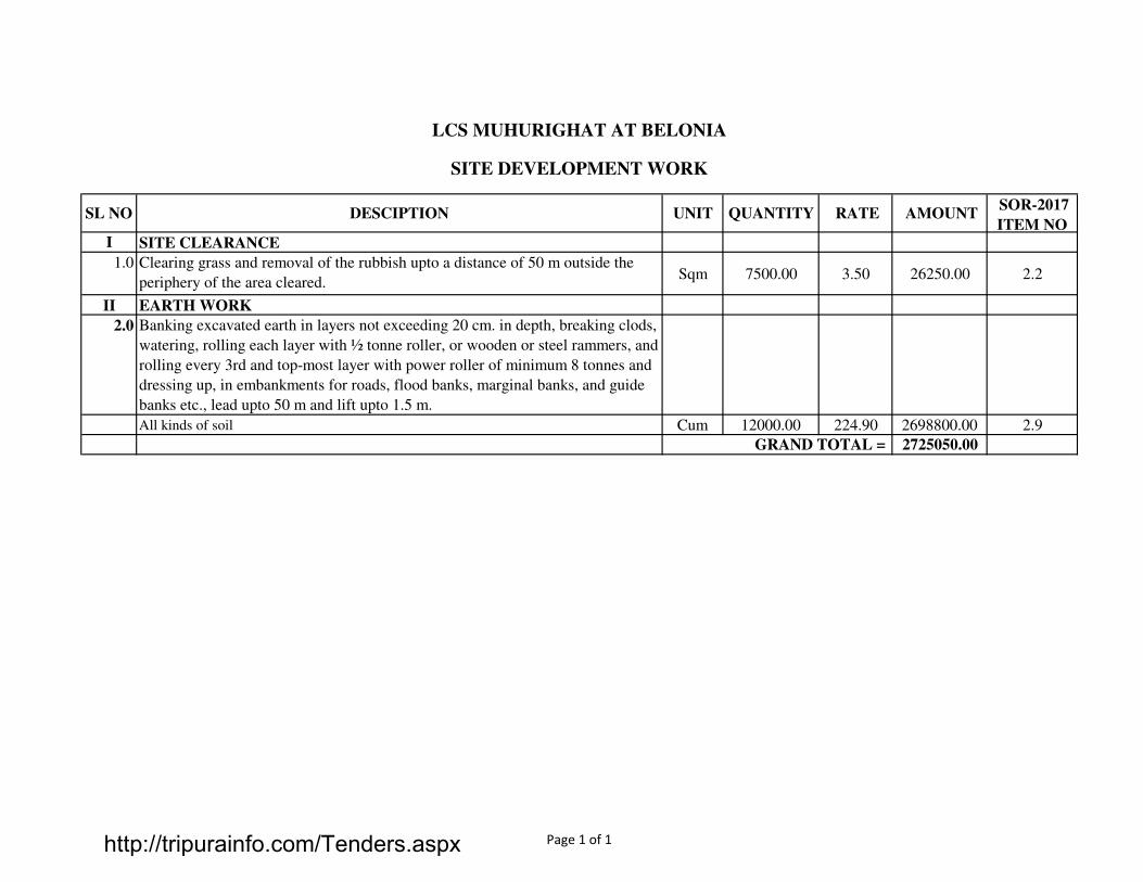
I SITE CLEARANCE
1.0 Clearing grass and removal of the rubbish upto a distance of 50 m outside the
periphery of the area cleared.Sqm 7500.00 3.50 26250.00 2.2
II EARTH WORK
2.0 Banking excavated earth in layers not exceeding 20 cm. in depth, breaking clods,
watering, rolling each layer with ½ tonne roller, or wooden or steel rammers, and
rolling every 3rd and top-most layer with power roller of minimum 8 tonnes and
dressing up, in embankments for roads, flood banks, marginal banks, and guide
banks etc., lead upto 50 m and lift upto 1.5 m.
All kinds of soil Cum 12000.00 224.90 2698800.00 2.9
2725050.00
LCS MUHURIGHAT AT BELONIA
SITE DEVELOPMENT WORK
SOR-2017
ITEM NO
GRAND TOTAL =
SL NO DESCIPTION UNIT QUANTITY RATE AMOUNT
Page 1 of 1http://tripurainfo.com/Tenders.aspx