outboards.yamaha-owners-manuals.com · title: lit-18626-11-55.pdf author: petertang created date:...
TRANSCRIPT

Read this manual carefully before operating thisoutboard motor.
OWNER’S MANUAL
F150LF150
LIT-18626-11-5563P-28199-3K-E0
©2019 Yamaha M
otor Corporation, U.S.A.

ZMU07696
Les gaz d’échappement du moteur de ce produit contiennent des substances chimiques connues dans l’État de Californie pour provoquer le cancer, des anomalies congénitales et des troubles de la reproduction.
Read this manual carefully before operating this outboard motor. Keep thismanual onboard in a waterproof bag when boating. This manual should staywith the outboard motor if it is sold.
©2019 Yamaha M
otor Corporation, U.S.A.

Important manual informationEMU44141
To the ownerThank you for selecting a Yamaha outboard
motor. This Owner’s Manual contains infor-
mation needed for proper operation, mainte-
nance and care. A thorough understanding of
these simple instructions will help you obtain
maximum enjoyment from your new Yamaha.
If you have any question about the operation
or maintenance of your outboard motor,
please consult a Yamaha dealer.
In this Owner’s Manual particularly important
information is distinguished in the following
ways.
: This is the safety alert symbol. It is used
to alert you to potential personal injury haz-
ards. Obey all safety messages that follow
this symbol to avoid possible injury or death.
WARNINGEWM00782
A WARNING indicates a hazardous situa-tion which, if not avoided, could result indeath or serious injury.
NOTICEECM00702
A NOTICE indicates special precautionsthat must be taken to avoid damage to theoutboard motor or other property.
TIP:A TIP provides key information to make pro-
cedures easier or clearer.
Yamaha continually seeks advancements in
product design and quality. Therefore, while
this manual contains the most current prod-
uct information available at the time of print-
ing, there may be minor discrepancies
between your machine and this manual. If
there is any question concerning this manual,
please consult your Yamaha dealer.
To ensure long product life, Yamaha recom-
mends that you use the product and perform
the specified periodic inspections and main-
tenance by correctly following the instruc-
tions in the owner’s manual. Any damage
resulting from neglect of these instructions is
not covered by warranty.
Some countries have laws or regulations re-
stricting users from taking the product out of
the country where it was purchased, and it
may be impossible to register the product in
the destination country. Additionally, the war-
ranty may not apply in certain regions. When
planning to take the product to another coun-
try, consult the dealer where the product was
purchased for further information.
If you purchased this outboard motor used,
see your Yamaha dealer to have it registered
in your name in Yamaha records.
TIP:The F150B, LF150B and the standard acces-
sories are used as a base for the explanations
and illustrations in this manual. Therefore
some items may not apply to every model.EMU44151
F150, LF150OWNER’S MANUAL
©2016 by Yamaha Motor Co., Ltd.1st Edition, November 2016
All rights reserved.Any reprinting or unauthorized usewithout the written permission of
Yamaha Motor Co., Ltd.is expressly prohibited.
Printed in Japan
©2019 Yamaha M
otor Corporation, U.S.A.

Table of contents
Safety information.............................1Outboard motor safety.................... 1
Propeller ............................................. 1
Rotating parts..................................... 1
Hot parts ............................................ 1
Electric shock..................................... 1
Power trim and tilt .............................. 1
Engine shut-off cord (lanyard) ............ 1
Gasoline ............................................. 2
Gasoline exposure and spills ............. 2
Carbon monoxide .............................. 2
Modifications...................................... 2
Boating safety ................................. 2Alcohol and drugs .............................. 2
Personal flotation devices (PFDs) ...... 2
People in the water ............................ 2
Passengers......................................... 2
Overloading........................................ 2
Avoid collisions .................................. 3
Weather .............................................. 3
Accident reporting.............................. 3
Boat education and training............... 3
Passenger training ............................. 4
Boating safety publications................ 4
Laws and regulations ......................... 4
Boating organizations ..................... 4
Basic boating rules (Rules of the
road) ............................................. 5Steering and sailing rules and sound
signals............................................. 5
Rules when encountering vessels...... 5
Other special situations...................... 6
General information ..........................9Identification numbers record ......... 9
Outboard motor serial number........... 9
Key number........................................ 9
EC Declaration of Conformity
(DoC)............................................ 9
CE Marking ..................................... 9
Compliance mark and
manufactured date label............ 10
Read manuals and labels ............. 12Warning labels ................................. 12
Specifications and requirements ................................... 15
Specifications ............................... 15
Installation requirements .............. 16Boat horsepower rating.................... 16
Mounting outboard motor ................ 16
Remote control requirements ....... 16
Battery requirements .................... 17Battery specifications....................... 17
Propeller selection ........................ 17Counter rotation models .................. 18
Start-in-gear protection ................ 18
Engine oil requirements ................ 19
Fuel requirements ......................... 19Gasoline ........................................... 19
Gasoline Additives............................ 21
Muddy or acidic water .................. 21
Anti-fouling paint .......................... 21
Outboard motor disposal
requirements.............................. 22
Emergency equipment.................. 22
Emission control information ....... 22Star labels ........................................ 23
Components.................................... 25Components diagram ................... 25
Optional items .................................. 27
Yamaha Security System (Y-COP)... 27
Remote control box.......................... 28
Remote control lever ........................ 28
Neutral interlock trigger.................... 29
Neutral throttle lever......................... 29
Free accelerator ............................... 29
Throttle friction adjuster ................... 30
©2019 Yamaha M
otor Corporation, U.S.A.

Table of contents
Engine shut-off cord (lanyard) and
clip ................................................ 30
Main switch ...................................... 31
Power trim and tilt switch on remote
control........................................... 31
Power trim and tilt switch on bottom
cowling.......................................... 32
Power trim and tilt switches (twin
binnacle type) ............................... 32
Trim tab with anode ......................... 33
Tilt support lever for power trim
and tilt model ................................ 33
Cowling lock lever ............................ 34
Flushing device ................................ 34
Fuel filter........................................... 34
Instruments and indicators ............ 35Digital tachometer ......................... 35
Tachometer ...................................... 35
Trim meter ........................................ 35
Hour meter ....................................... 35
Low oil pressure-alert indicator........ 35
Overheat-alert indicator ................... 36
Digital speedometer ...................... 36Speedometer.................................... 36
Fuel gauge........................................ 37
Trip meter / Clock / Voltmeter.......... 37
Fuel level-alert indicator ................... 38
Low battery voltage-alert
indicator ........................................ 38
Fuel management meter ............... 38Fuel flow meter................................. 38
Fuel consumption meter / Fuel
economy meter / Twin engine
speed synchronizer....................... 39
Water separator-alert indicator ........ 41
6YC Multifunction meter ............... 41
6Y8 Multifunction meters .............. 44
Engine control system .................... 48Alert system .................................. 48
Overheat alert................................... 48
Low oil pressure alert ....................... 49
Water separator alert........................ 49
Installation ....................................... 51Installation..................................... 51
Mounting the outboard motor .......... 51
Operation......................................... 53First-time operation ...................... 53
Fill engine oil..................................... 53
Breaking in engine............................ 53
Getting to know your boat ............... 53
Checks before starting engine...... 53Fuel level .......................................... 54
Removing top cowling...................... 54
Fuel system ...................................... 54
Controls............................................ 55
Engine shut-off cord (lanyard) .......... 55
Engine oil.......................................... 55
Engine .............................................. 56
Flushing device ................................ 56
Installing top cowling ....................... 56
Checking power trim and tilt
system........................................... 57
Battery.............................................. 58
Filling fuel ..................................... 59
Operating engine .......................... 59Sending fuel ..................................... 59
Starting engine ................................. 60
Checks after starting engine......... 61Cooling water ................................... 61
Warming up engine....................... 62Procedure for warming up engine.... 62
Checks after engine warm up....... 62Shifting ............................................. 62
Stop switches................................... 62
Shifting.......................................... 62
Stopping boat ............................... 64
Stopping engine............................ 64Procedure......................................... 64
Trimming outboard motor............. 64Adjusting trim angle (Power trim
and tilt) .......................................... 65
Adjusting boat trim ........................... 65
Tilting up and down ...................... 66Procedure for tilting up..................... 67
©2019 Yamaha M
otor Corporation, U.S.A.

Table of contents
Procedure for tilting down................ 68
Shallow water ............................... 69Cruising in shallow water ................. 69
Operating in other conditions ....... 70
Maintenance .................................... 71Transporting and storing outboard
motor.......................................... 71Storing outboard motor.................... 71
Conditioning and stabilizing
gasoline......................................... 71
Procedure......................................... 72
Lubrication ....................................... 73
Cleaning and anticorrosion
measures ...................................... 73
Flushing cooling water passage....... 73
Cleaning the outboard motor ........... 74
Checking painted surface of
outboard motor............................. 74
Periodic maintenance ................... 75Replacement parts ........................... 75
Maintenance interval guidelines....... 75
Maintenance chart 1 ........................ 76
Maintenance chart 2 ........................ 78
Greasing........................................... 79
Inspecting spark plug....................... 80
Inspecting idle speed ....................... 81
Changing engine oil.......................... 81
Inspecting wiring and connectors .... 84
Checking propeller ........................... 84
Removing propeller .......................... 85
Installing propeller ............................ 85
Changing gear oil ............................. 86
Inspecting and replacing anode(s) ... 88
Checking battery (for electric start
models) ......................................... 88
Connecting the battery..................... 89
Disconnecting the battery ................ 90
Trouble Recovery ............................ 92Troubleshooting ............................ 92
Temporary action in emergency ... 95Impact damage ................................ 95
Running single engine (twin
engines)......................................... 95
Replacing fuse.................................. 96
Power trim and tilt will not
operate.......................................... 96
Water separator-alert indicator
blinks while cruising...................... 97
Treatment of submerged motor.... 98
Consumer information (For North America) ........................ 99
YAMAHA FOUR-STROKE
OUTBOARD MOTOR
THREE-YEAR LIMITED
WARRANTY............................... 99
IMPORTANT WARRANTY
INFORMATION IF YOU USE
YOUR YAMAHA OUTSIDE
THE U.S.A. OR CANADA......... 101
INDEX............................................. 102
©2019 Yamaha M
otor Corporation, U.S.A.
1
Safety informationEMU33623
Outboard motor safetyObserve these precautions at all times.EMU36502
PropellerPeople can be injured or killed if they come in
contact with the propeller. The propeller can
keep moving even when the motor is in neu-
tral, and sharp edges of the propeller can cut
even when stationary.
Stop the engine when a person is in the
water near you.
Keep people out of reach of the propeller,
even when the engine is off.EMU40272
Rotating partsHands, feet, hair, jewelry, clothing, personal
flotation device (PFD) straps, etc., can be-
come entangled with internal rotating parts of
the engine, resulting in serious injury or
death.
Keep the top cowling in place whenever pos-
sible. Do not remove or replace the top cowl-
ing with the engine running.
Only operate the engine with the top cowling
removed according to the specific instruc-
tions in the manual. Keep hands, feet, hair,
jewelry, clothing, PFD straps, etc., away from
any exposed moving parts.EMU33641
Hot partsDuring and after operation, engine parts are
hot enough to cause burns. Avoid touching
any parts under the top cowling until the en-
gine has cooled.EMU33651
Electric shockDo not touch any electrical parts while start-
ing or operating the engine. They can cause
shock or electrocution.
EMU33661
Power trim and tiltBody parts can be crushed between the mo-
tor and the clamp bracket when the motor is
trimmed or tilted. Keep body parts out of this
area at all times. Be sure no one is in this area
before operating the power trim and tilt
mechanism.
The power trim and tilt switches operate even
when the main switch is off. Keep people be
away from the switches whenever working
around the motor.
Never get under the lower unit while it is tilted,
even when the tilt support lever is locked. Se-
vere injury could occur if the outboard motor
accidentally falls.EMU33672
Engine shut-off cord (lanyard)Attach the engine shut-off cord so that the
engine stops if the operator falls overboard or
leaves the helm. This prevents the boat from
running away under power and leaving peo-
ple stranded, or running over people or ob-
jects.
Always attach the engine shut-off cord to a
secure place on your clothing or your arm or
leg while operating. Do not remove it to leave
the helm while the boat is moving. Do not at-
tach the cord to clothing that could tear
loose, or route the cord where it could be-
come entangled, preventing it from function-
ing.
Do not route the cord where it is likely to be
accidentally pulled out. If the cord is pulled
during operation, the engine will shut off and
you will lose most steering control. The boat
could slow rapidly, throwing people and ob-
jects forward.
©2019 Yamaha M
otor Corporation, U.S.A.
Safety information
2
EMU33811
GasolineGasoline and its vapors are highly flamma-ble and explosive. Always, refuel according
to the procedure on page 59 to reduce the
risk of fire and explosion.EMU33821
Gasoline exposure and spillsTake care not to spill gasoline. If gasoline
spills, wipe it up immediately with dry rags.
Dispose of rags properly.
If any gasoline spills onto your skin, immedi-
ately wash with soap and water. Change
clothing if gasoline spills on it.
If you swallow gasoline, inhale a lot of gaso-
line vapor, or get gasoline in your eyes, get
immediate medical attention. Never siphon
fuel by mouth.EMU33901
Carbon monoxideThis product emits exhaust gases which con-
tain carbon monoxide, a colorless, odorless
gas which may cause brain damage or death
when inhaled. Symptoms include nausea,
dizziness, and drowsiness. Keep cockpit and
cabin areas well ventilated. Avoid blocking
exhaust outlets.EMU33781
ModificationsDo not attempt to modify this outboard mo-
tor. Modifications to your outboard motor
may reduce safety and reliability, and render
the outboard unsafe or illegal to use.EMU33741
Boating safetyThis section includes a few of the many im-
portant safety precautions that you should
follow when boating.EMU33711
Alcohol and drugsNever operate after drinking alcohol or taking
drugs. Intoxication is one of the most com-
mon factors contributing to boating fatalities.
EMU40281
Personal flotation devices (PFDs)Have an approved PFD on board for every
occupant. Yamaha recommends that you
must wear a PFD whenever boating. At a mi-
nimum, children and non-swimmers should
always wear PFDs, and everyone should
wear PFDs when there are potentially hazard-
ous boating conditions.EMU33732
People in the waterAlways watch carefully for people in the wa-
ter, such as swimmers, skiers, or divers,
whenever the engine is running. When some-
one is in the water near the boat, shift into
neutral and stop the engine.
Stay away from swimming areas. Swimmers
can be hard to see.
The propeller can keep moving even when
the motor is in neutral. Stop the engine when
a person is in the water near you.EMU33752
PassengersConsult your boat manufacturer’s instruc-
tions for details about appropriate passenger
locations in your boat and be sure all passen-
gers are positioned properly before acceler-
ating and when operating above an idle
speed. Standing or sitting in non-designated
locations may result in being thrown either
overboard or within the boat due to waves,
wakes, or sudden changes in speed or direc-
tion. Even when people are positioned prop-
erly, alert your passengers if you must make
any unusual maneuver. Always avoid jump-
ing waves or wakes.EMU33762
OverloadingDo not overload the boat. Consult the boat
capacity plate or boat manufacturer for maxi-
mum weight and number of passengers. Be
sure that weight is properly distributed ac-
cording to the boat manufacturer’s instruc-
©2019 Yamaha M
otor Corporation, U.S.A.

Safety information
3
tions. Overloading or incorrect weight
distribution can compromise the boats han-
dling and lead to an accident, capsizing or
swamping.EMU33773
Avoid collisionsScan constantly for people, objects, and oth-
er boats. Be alert for conditions that limit your
visibility or block your vision of others.
Operate defensively at safe speeds and keep
a safe distance away from people, objects,
and other boats.
Do not follow directly behind other boats or
waterskiers.
Avoid sharp turns or other maneuvers that
make it hard for others to avoid you or un-
derstand where you are going.
Avoid areas with submerged objects or
shallow water.
Ride within your limits and avoid aggres-
sive maneuvers to reduce the risk of loss of
control, ejection, and collision.
Take early action to avoid collisions. Re-
member, boats do not have brakes, and
stopping the engine or reducing throttle
can reduce the ability to steer. If you are not
sure that you can stop in time before hitting
an obstacle, apply throttle and turn in an-
other direction.
EMU33791
WeatherStay informed about the weather. Check
weather forecasts before boating. Avoid
boating in hazardous weather.EMU44161
Accident reportingBoat operators are required by law to file a
Boating Accident Report with their boating
law enforcement agency if their boat is in-
volved in any of the following accidents:
1. There is loss of life or probable loss of
life.
2. There is personal injury that requires
medical attention beyond first aid.
3. There is property damage to boats or
other property over a certain amount.
4. There is complete loss of a boat.
Contact local law enforcement personnel if a
report is necessary.EMU44171
Boat education and trainingFor U.S.A.Operators should take a boating safety cour-
se. This may be required in your state. Many
of the organizations listed in the next section
can provide information about courses in
your area.
You may also want to consider an Internet-
based program for basic boater education.
The Online Boating Safety Course provided
by the BoatU.S. Foundation, is approved by
the National Association of State Boating
Law Administrators (NASBLA) and recog-
nized by the United States Coast Guard.
Most, but not all, states accept this course to
meet their minimum requirements. While it
cannot replace an in-depth course such as
one offered by the U.S. Coast Guard, U.S.
Power Squadron, or other organization, this
online course does provide a general over-
view of the basics in boating safety, require-
ments, navigation, and operation. Upon
ZMU06025
©2019 Yamaha M
otor Corporation, U.S.A.

Safety information
4
successful completion of the course, the user
can download a certificate of completion im-
mediately or, for a small charge, request one
by mail. To take this free course, go to boa-
tus.org.
For CanadaAll operators of pleasure craft must illustrate
competency by means of a Pleasure Craft
Operators Card with the exception of Person-
al Water Craft used for rental purposes which
require a rental checklist be completed. Plea-
sure Craft Operators Cards can be obtained
following the completion of a competency
course, with an on-line option. Details can be
found on Transport Canada’s website.
www.tc.gc.caEMU33881
Passenger trainingMake sure at least one other passenger is
trained to operate the boat in the event of an
emergency.EMU33891
Boating safety publicationsBe informed about boating safety. Additional
publications and information can be obtained
from many boating organizations.EMU33592
Laws and regulationsKnow the marine laws and regulations where
you will be boating—and obey them. Several
sets of rules prevail according to geographic
location, but all are basically the same as the
International Rules of the Road. The rules
presented in the following section are con-
densed—and have been provided for your
convenience only.
Contact the U.S. Coast Guard, the National
Association of State Boating Law Administra-
tors, or your local Power Squadron for a com-
plete set of rules governing the waters in
which you will be using your boat.
EMU44740
Boating organizationsThe following organizations provide boating
safety training and information about boating
safety and laws.
In the U.S.A.United States Coast GuardConsumer Affairs Staff (G-BC)
Office of Boating, Public, and Consumer Af-
fairs
U.S. Coast Guard Headquarters
Washington, D.C. 20593-0001
http://www.uscgboating.org/
United States Power Squadrons1-888-FOR-USPS (1-888-367-8777)
http://www.usps.org/
Boat Owners Association of The UnitedStates1-800-336-BOAT (1-800-336-2628)
http://www.boatus.com/
National Association of State Boating LawAdministrators (NASBLA)1500 Leestown Road, Suite 330
Lexington, KY 40511 859-225-9497
http://www.nasbla.org/
National Marine Manufacturers Associa-tion (NMMA)200 East Randolph Drive
Suite 5100
Chicago, IL 60601
http://www.nmma.org/
Marine Retailers Association of America155 N. Michigan Ave. Chicago,
IL 60304
http://www.mraa.com/
©2019 Yamaha M
otor Corporation, U.S.A.

Safety information
5
In CanadaNational Marine Manufacturers Associa-tion Canada14 McEwan Drive
Suite 8
Bolton, ON
L7E 1H1
http://www.nmma.org/
In AustraliaBoating Industry Association of Australiahttp://www.biaa.com.au/
In New ZealandNZ Marine Industry Associationhttp://www.nzmarine.com/
EMU33692
Basic boating rules (Rules of the road)
Just as there are rules that apply when you
are driving on streets and highways, there are
waterway rules that apply when you are driv-
ing your boat. These rules are used interna-
tionally. (For U.S.A.: and are also enforced by
the United States Coast Guard and local
agencies.) You should be aware of these
rules, and follow them whenever you encoun-
ter another vessel on the water.EMU33702
Steering and sailing rules and sound signalsWhenever two vessels on the water meet one
another, one vessel has the right-of-way; it is
called the “stand-on” vessel. The vessel that
does not have the right-of-way is called the
“give-way” or “burdened” vessel. These rules
determine which vessel has the right-of-way,
and what each vessel should do.
Stand-on vesselThe vessel with the right-of-way has the duty
to continue its course and speed, except to
avoid an immediate collision. When you
maintain your direction and speed, the other
vessel will be able to determine how best to
avoid you.
Give-way vesselThe vessel that does not have the right-of-
way has the duty to take positive and timely
action to stay out of the way of the Stand-On
vessel. Normally, you should not cross in
front of the vessel with the right-of-way. You
should slow down or change directions brief-
ly and pass behind the other vessel. You
should always move in such a way that the
operator of the other vessel can see what you
are doing.
“The general prudential rule”This rule is called Rule 2 in the International
Rules and says,
“In obeying and construing these rules due
regard shall be had to all dangers of naviga-
tion and collision, and to any special circum-
stances, which may render a departure from
the above rules necessary in order to avoid
immediate danger.”
In other words, follow the standard rules ex-
cept when a collision will occur unless both
vessels try to avoid each other. If that is the
case, both vessels become “Give-Way” ves-
sels.EMU25522
Rules when encountering vesselsThere are three main situations that you may
encounter with other vessels which could
lead to a collision unless the Steering Rules
are followed:
Meeting: (you are approaching another ves-
sel head-on)
©2019 Yamaha M
otor Corporation, U.S.A.

Safety information
6
Crossing: (you are traveling across the other
vessel’s path)
Overtaking: (you are passing or being
passed by another vessel)
In the following illustration, your boat is in the
center. You should give the right-of-way to
any vessels shown in white area (you are the
Give-Way vessel). Any vessels in the shaded
area must yield to you (they are the Give-Way
vessels). Both you and the meeting vessel
must alter course to avoid each other.
MeetingIf you are meeting another power vessel head
on, and are close enough to run the risk of
collision, neither of you has the right-of-way
Both of you should alter course to avoid an
accident. You should keep the other vessel
on your port (left) side. This rule doesn’t apply
if both of you will clear one another if you con-
tinue on your set course and speed.
CrossingWhen two power driven vessels are crossing
each other’s path close enough to run the risk
of collision, the vessel which has the other on
the starboard (right) side must keep out of the
way of the other. If the other vessel is on your
right, you must keep out of its way; you are
the Give-Way vessel. If the other vessel is on
your port (left) side, remember that you
should maintain course and direction, provid-
ed the other vessel gives you the right-of-way
as it should.
OvertakingIf you are passing another vessel, you are the
“Give-Way” vessel. This means that the other
vessel is expected to maintain its course and
speed. You must stay out of its way until you
are clear of it. Likewise, if another vessel is
passing you, you should maintain your speed
and direction so that the other vessel can
steer itself around you.EMU25532
Other special situationsThere are three other rules you should be
aware of when driving your boat around other
vessels.
Narrow channels and bendsWhen navigating in narrow channels, you
should keep to the right when it is safe and
practical to do so. If the operator of a power-
driven vessel is preparing to go around a
bend that may obstruct the view of other wa-
©2019 Yamaha M
otor Corporation, U.S.A.

Safety information
7
ter vessels, the operator should sound a pro-
longed blast on the whistle (4 to 6 seconds).
If another vessel is around the bend, it too
should sound the whistle. Even if no reply is
heard, however, the vessel should still pro-
ceed around the bend with caution. If you
navigate such waters with your boat, you will
need to carry a portable air horn, available
from local marine supply stores.
Fishing vessel right-of-wayAll vessels that are fishing with nets, lines or
trawls are considered to be “fishing vessels”
under the International Rules. Vessels with
trolling lines are not considered fishing ves-
sels. Fishing vessels have the right-of-way
regardless of position. Fishing vessels can-
not, however, impede the passage of other
vessels in narrow channels.
Sailing vessel right-of-waySailing vessels should normally be given the
right-of-way. The exceptions to this are:
1. When the sailing vessel is overtaking the
power-driven vessel, the power-driven
vessel has the right-of-way.
2. Sailing vessels should keep clear of any
fishing vessel.
3. In a narrow channel, a sailing vessel
should not hamper the safe passage of a
power-driven vessel that can navigate
only in such a channel.
Reading buoys and other markersThe waters of the United States are marked
for safe navigation by the lateral system of
buoyage. Simply put, buoys and markers
have an arrangement of shapes, colors, num-
bers and lights to show which side of the
buoy a boater should pass on when navigat-
ing in a particular direction. The markings on
these buoys are oriented from the perspec-
tive of being entered from seaward (the boat-
er is going towards the port). This means that
red buoys are passed on the starboard (right)
side when proceeding from open water into
port, and black buoys are to port (left) side.
When navigating out of port, your position
with respect to the buoys should be reversed;
red buoys should be to port and black buoys
to starboard.
Many bodies of water used by boaters are
entirely within the boundaries of a particular
state. The Uniform State Waterway Marking
System has been devised for these waters.
This system uses buoys and signs with dis-
tinctive shapes and colors to show regulatory
or advisory information. These markers are
white with black letters and orange boarders.
They signify speed zones, restricted areas,
danger areas, and general information.
Remember, markings may vary by geograph-
ic location. Always consult local boating au-
thorities before driving your boat in unfamiliar
waters.
©2019 Yamaha M
otor Corporation, U.S.A.

Safety information
8
ZMU01708
©2019 Yamaha M
otor Corporation, U.S.A.

General information
9
EMU25172
Identification numbers recordEMU25186
Outboard motor serial numberThe outboard motor serial number is
stamped on the label attached to the port
side of the clamp bracket.
Record your outboard motor serial number in
the spaces provided to assist you in ordering
spare parts from your Yamaha dealer or for
reference in case your outboard motor is sto-
len.
EMU25192
Key numberIf a main key switch is equipped with the mo-
tor, the key identification number is stamped
on your key as shown in the illustration. Re-
cord this number in the space provided for
reference in case you need a new key.
EMU38981
EC Declaration of Conformity (DoC)
This declaration is included with outboard
motors that conform to European regula-
tions.
This outboard motor conforms to certain por-
tions of the European Parliament directive re-
lating to machinery.
Each conformed outboard motor accompa-
nied with EC DoC.EC DoC contains the fol-
lowing information;
Name of Engine Manufacture
Model name
Product code of model (Approved model
code)
Code of conformed directivesEMU38995
CE MarkingThis label is affixed to outboard motors that
conform to European regulations.
1. Outboard motor serial number location
1. Serial number
2. Model name
3. Motor transom height
4. Approved model code
1
ZMU08223
34 12
ZMU01692
1. Key number
1
ZMU01694
©2019 Yamaha M
otor Corporation, U.S.A.

General information
10
Outboard motors affixed with this “CE” mark-
ing conform with the directives of;
2006/42/EC, 94/25/EC - 2003/44/EC,
2014/30/EU, and 2004/108/EC, 2013/53/EU.
EMU46132
Compliance mark and manu-factured date label
Engines affixed with this label conform to the
regulations for each country.
This label is affixed to the clamp bracket or
swivel bracket.
Regulatory Compliance Mark (RCM)Engines affixed with this mark conform to
certain portion(s) of the Australian Radio
Communications Act.
ICES-002 Compliance LabelEngines affixed with this mark meet all re-
quirements of the Canadian Interference
Causing Equipment Regulations.
1. CE marking location
1
ZMU08264
ZMU06040
1. Compliance mark and manufactured date label location
1. Regulatory Compliance Mark (RCM)
1. ICES-002 Compliance Label
1
ZMU08266
ZMU08190
1
ZMU081911
©2019 Yamaha M
otor Corporation, U.S.A.

General information
11
Manufactured dateThe manufactured date is stamped on the la-
bel for the engines that conform to the regu-
lations for U.S. Environmental Protection
Agency (EPA). The models that manufac-
tured exclusively for the Oceanian countries
may not have manufactured date on the la-
bel.
1. Manufactured date
ZMU08192
1
©2019 Yamaha M
otor Corporation, U.S.A.

General information
12
EMU33524
Read manuals and labelsBefore operating or working on this outboard motor:
Read this manual.
Read any manuals supplied with the boat.
Read all labels on the outboard motor and the boat.
If you need any additional information, contact your Yamaha dealer.EMU33836
Warning labels If these labels are damaged or missing, contact your Yamaha dealer for replacements.
23
1
ZMU06189
©2019 Yamaha M
otor Corporation, U.S.A.

General information
13
EMU34652
Contents of labelsThe above warning labels mean as follows.
1
WARNINGEWM01682
Keep hands, hair, and clothing awayfrom rotating parts while the engine isrunning.Do not touch or remove electrical partswhen starting or during operation.
2
WARNINGEWM01672
Read Owner’s Manuals and labels.Wear an approved personal flotation de-vice (PFD).
Attach engine shut-off cord (lanyard) toyour PFD, arm, or leg so the enginestops if you accidentally leave the helm,which could prevent a runaway boat.
EMU33851
Other labels
6EE-G2794-40
6EE-H1994-40
1 2
6EE-G2794-50
6EE-H1994-50
ZMU06191
3
ZMU05710
©2019 Yamaha M
otor Corporation, U.S.A.

General information
14
EMU35133
SymbolsThe following symbols mean as follows.
Notice/Warning
Read Owner’s Manual
Hazard caused by continuous rotation
Electrical hazard
ZMU05696
ZMU05664
ZMU05665
ZMU05666
©2019 Yamaha M
otor Corporation, U.S.A.

Specifications and requirements
15
EMU40501
SpecificationsTIP:“(SUS)” indicates that the specification is for
the outboard motor when it is equipped with
a stainless steel propeller.EMU2821V
Dimension and weight:Overall length:
920 mm (36.2 in)
Overall width:
548 mm (21.6 in)
Overall height L:
1742 mm (68.6 in) (F150B)
Overall height X:
1869 mm (73.6 in)
Motor transom height L:
516 mm (20.3 in) (F150B)
Motor transom height X:
643 mm (25.3 in)
Dry weight (SUS) L:
222 kg (489 lb) (F150B)
Dry weight (SUS) X:
227 kg (500 lb)
Performance:Full throttle operating range:
5000–6000 r/min
Rated power:
110.3 kW (150 HP)
Idle speed (in neutral):
650–750 r/min
Power unit:Type:
4-stroke DOHC L4 16 valves
Total displacement:
2670 cm³ (162.9 c.i.)
Bore × stroke:
94.0 × 96.2 mm (3.70 × 3.79 in)
Ignition system:
TCI
Spark plug (NGK):
LFR5A-11
Spark plug gap:
1.0–1.1 mm (0.039–0.043 in)
Steering system:
Remote steering
Starting system:
Electric starter
Starting carburetion system:
Fuel injection
Valve clearance IN (cold engine):
0.17–0.24 mm (0.0067–0.0094 in)
Valve clearance EX (cold engine):
0.31–0.38 mm (0.0122–0.0150 in)
Battery rating (CCA/SAE):
512–1150 A
Battery rating (MCA/ABYC):
675–1370 A
Battery rating (RC/SAE):
124 minutes
Battery rating (CCA/EN):
510–1080 A
Battery rating (20HR/IEC):
80 Ah
Maximum generator output:
35 A
Lower unit:Gear shift positions:
Forward-neutral-reverse
Gear ratio:
2.00 (28/14)
Trim and tilt system:
Power trim and tilt
Propeller mark:
M/T (F150B)
ML/TL (LF150B)
Fuel and oil:Recommended fuel:
Regular unleaded gasoline
Min. pump octane number (PON):
86
©2019 Yamaha M
otor Corporation, U.S.A.

Specifications and requirements
16
Min. research octane number (RON):
90
Recommended engine oil:
YAMALUBE 4M FC-W or 4-stroke
outboard motor oil
Recommended engine oil grade 1:
SAE 10W-30/10W-40/5W-30
API SE/SF/SG/SH/SJ/SL
Engine oil quantity (without oil filter
replacement):
4.3 L (4.55 US qt, 3.78 Imp.qt)
Engine oil quantity (with oil filter
replacement):
4.5 L (4.76 US qt, 3.96 Imp.qt)
Lubrication system:
Wet sump
Recommended gear oil:
Yamalube Marine Gearcase Lube HD or
Hypoid gear oil
Recommended gear oil grade:
SAE 90 API GL-4 / SAE 80W API GL-5 /
SAE 90 API GL-5
Gear oil quantity:
0.980 L (1.036 US qt, 0.862 Imp.qt)
Tightening torque:Spark plug:
25 N·m (2.55 kgf·m, 18.4 lb·ft)
Propeller nut:
54 N·m (5.51 kgf·m, 39.8 lb·ft)
Engine oil drain bolt:
27 N·m (2.75 kgf·m, 19.9 lb·ft)
Engine oil filter:
18 N·m (1.84 kgf·m, 13.3 lb·ft)EMU33556
Installation requirementsEMU33565
Boat horsepower rating
WARNINGEWM01561
Overpowering a boat can cause severe in-stability.
Before installing the outboard motor(s), con-
firm that the total horsepower of your out-
board motor(s) does not exceed the boats
maximum horsepower rating. See the boat’s
capacity plate or contact the manufacturer.EMU40491
Mounting outboard motor
WARNINGEWM02501
Improper mounting of the outboard mo-tor could result in hazardous conditionssuch as poor handling, loss of control,or fire hazards.Because the outboard motor is veryheavy, special equipment and training isrequired to mount it safely.
Your dealer or other person experienced in
proper rigging should mount the outboard
motor using correct equipment and complete
rigging instructions. For further information,
see page 51.EMU33582
Remote control requirements
WARNINGEWM01581
If the engine starts in gear, the boat canmove suddenly and unexpectedly, pos-sibly causing a collision or throwingpassengers overboard.If the engine ever starts in gear, thestart-in-gear protection device is notworking correctly and you should dis-continue using the outboard. Contactyour Yamaha dealer.
The remote control unit must be equipped
with a start-in-gear protection device(s). This
device prevents the engine from starting un-
less it is in neutral.
©2019 Yamaha M
otor Corporation, U.S.A.

Specifications and requirements
17
EMU25695
Battery requirementsEMU44723
Battery specificationsStandard lead-acid, AGM, gel-cell, and main-
tenance-free batteries are permitted. Use a
fully charged battery that meets the following
specifications. The battery is an important
component necessary to obtain sure engine
starting and to maintain engine performance.
The engine may not start if the battery voltage
is too low.
For North AmericaIt is necessary to meet only two of the three
specifications (CCA, MCA, and RC) in one of
the following combinations:
CCA/SAE and RC
MCA/ABYC and RC
For OceaniaIt is necessary to meet the following specifi-
cations.
NOTICEECM01063
Do not use a battery that does not meetthe specified capacity. If a battery thatdoes not meet specifications is used,the electric system could perform poor-ly or be overloaded, causing electricsystem damage.
Do not use a battery which exceeds themaximum CCA rating. If the batteriesare used in parallel circuit, use new bat-teries of the same type and make surethat the total battery rating never ex-ceed the maximum CCA rating.
EMU36293
Mounting batteryMount the battery holder securely in a dry,
well-ventilated, vibration-free location in the
boat. WARNING! Do not put flammableitems, or loose heavy or metal objects inthe same compartment as the battery.Fire, explosion or sparks could result.[EWM01821]
Battery cableThe battery cable size and length are critical.
Consult your Yamaha dealer about the bat-
tery cable size and length.EMU36303
Multiple batteriesTo connect multiple batteries, such as for
multiple engine configurations or for an ac-
cessory battery, consult your Yamaha dealer
about battery selection and correct wiring.
Battery isolatorYour outboard motor is capable of charging
an accessory battery separate from the start-
ing battery using an optional isolator lead.
Contact your Yamaha dealer for installation
of an optional isolator lead with over-current
protection.EMU41603
Propeller selectionNext to selecting an outboard motor, select-
ing the right propeller is one of the most im-
portant purchasing decisions a boater can
make. The type, size, and design of your pro-
peller have a direct impact on acceleration,
top speed, fuel economy, and even engine
Battery rating (CCA/SAE):512–1150 A
Battery rating (MCA/ABYC):675–1370 A
Battery rating (RC/SAE):124 minutes
Battery rating (CCA/EN):510–1080 A
Battery rating (20HR/IEC):80 Ah
©2019 Yamaha M
otor Corporation, U.S.A.

Specifications and requirements
18
life. Yamaha designs and manufactures pro-
pellers for every Yamaha outboard motor and
every application.
Your Yamaha dealer can help you select the
right propeller for your boating needs. Select
a propeller that will allow the engine to reach
the middle or upper half of the operating
range at full throttle with the maximum boat-
load. Generally, select a larger pitch propeller
for a smaller operating load and a smaller
pitch propeller for a heavier load. If you carry
loads that vary widely, select the propeller
that lets the engine run in the proper range for
your maximum load but remember that you
may need to reduce your throttle setting to
stay within the recommended engine speed
range when carrying lighter loads.
Yamaha recommends to use a propeller suit-
able for the “Shift Dampener System (SDS)”.
For further information, consult your Yamaha
dealer.
To check the propeller, see page 84.
EMU36313
Counter rotation modelsStandard outboard motors rotate clockwise.
Counter rotation models rotate counterclock-
wise and are typically used in multiple motor
setups.
On counter rotation models, be sure to use a
propeller intended for counterclockwise rota-
tion. These propellers are identified with the
letter “L” after the size indication on the pro-
peller. WARNING! Never use a standardpropeller with a counter rotation motor, ora counter rotation propeller with a stan-dard motor. Otherwise the boat could goin the direction opposite of that expected(for example, reverse instead of forward),which could lead to an accident. [EWM01811]
For instructions on propeller removal and ins-
tallation, see page 85.EMU25771
Start-in-gear protectionYamaha outboard motors or Yamaha-ap-
proved remote control units are equipped
with start-in-gear protection device(s). This
feature permits the engine to be started only
when it is in neutral. Always select neutral be-
fore starting the engine.
1. Propeller diameter in inches
2. Propeller pitch in inches
3. Type of propeller (propeller mark)
ZMU04606
-x1 2 3
1. Propeller diameter in inches
2. Propeller pitch in inches
3. Type of propeller (propeller mark)
ZMU04607
-x1 2 3
©2019 Yamaha M
otor Corporation, U.S.A.

Specifications and requirements
19
EMU41953
Engine oil requirementsSelect an oil grade according to the average
temperatures in the area where the outboard
motor will be used.
If oil grades listed under Recommended en-
gine oil grade 1 are not available, select an al-
ternative oil grade listed under
Recommended engine oil grade 2.
Recommended engine oil grade 1
Recommended engine oil grade 2
EMU36361
Fuel requirementsEMU44791
GasolineUse a good quality gasoline that meets the
minimum octane requirement. If knocking or
pinging occurs, use a different brand of gas-
oline or premium unleaded fuel. Yamaha rec-
ommends that you use alcohol-free gasoline
(see Gasoline with Ethanol) whenever possi-
ble.
The use of a poor quality gasoline may result
in starting and running problems. If you en-
counter drivability problems, which you sus-
pect could be related to the fuel you are
using, Yamaha recommends that you switch
to a recognized high quality brand of gaso-
line, such as a gasoline that is advertised as
Top Tier Detergent Gasoline. (North America
only) NOTICE: Failure to comply with theserecommendations may also result in un-scheduled maintenance, fuel system dam-age, and internal engine damage. [ECM04480]
For North America
Recommended engine oil:YAMALUBE 4M FC-W or 4-stroke outboard motor oil
Recommended engine oil grade 1:SAE 10W-30/10W-40/5W-30 API SE/SF/SG/SH/SJ/SL
Recommended engine oil grade 2:SAE 15W-40/20W-40/20W-50 API SH/SJ/SLEngine oil quantity (without oil filter replacement):
4.3 L (4.55 US qt, 3.78 Imp.qt)Engine oil quantity (with oil filter re-placement):
4.5 L (4.76 US qt, 3.96 Imp.qt)
ZMU06854
122˚F
50˚C
104
40
86
30
68
SAE API
SESFSGSHSJSL
20
50
10
32
0
14
-10
-4
-20
10W–30
10W–40
5W–30
Recommended fuel:Regular unleaded gasoline
Min. pump octane number (PON):86
ZMU06855
122˚F
50˚C
104
40
86
30
68
SAE API
SHSJSL
20
50
10
32
0
14
-10
-4
-20
15W–40
20W–40
20W–50
©2019 Yamaha M
otor Corporation, U.S.A.

Specifications and requirements
20
For Oceania
NOTICEECM01982
Do not use leaded gasoline. Leadedgasoline can seriously damage the en-gine.Avoid getting water and contaminants inthe fuel tank. Contaminated fuel cancause poor performance or engine dam-age. Use only fresh gasoline that hasbeen stored in clean containers.
Gasoline with EthanolTwo types of gasoline are commonly avail-
able in the U.S.A., Canada, Australia and
New Zealand for use in automobiles and
boats: conventional gasoline without Ethanol
and gasoline with Ethanol, which is typically
referred to as E10 gasoline. According to fed-
eral regulations, E10 gasoline may contain up
to 10% Ethanol.
A high quality gasoline without Ethanol is the
preferred fuel for your Yamaha outboard mo-
tor. However, if gasoline with Ethanol is the
only fuel available in your area, your Yamaha
outboard motor is calibrated to run properly
on fresh E10 gasoline that meets the mini-
mum octane requirement specified for this
model.
NOTICEECM02402
Never use a gasoline for your outboardmotor that contains more than 10% Etha-nol, such as E15 which contains 15% Eth-anol or E85 which contains 85% Ethanol,or gasoline containing any amount of
Methanol. These fuels can cause startingand running problems, as well as seriousfuel system and internal engine damage.
Gasoline containing ethanol has several
properties that may cause boat fuel system
problems.
Ethanol is a strong solvent (cleaning agent)
that can clean gum and varnish deposits
from a boat’s fuel system, particularly in
older boats, as well as tanks and pipes
used in gasoline distribution. These re-
leased deposits contaminate the fuel and
can cause problems, such as clogged fuel
filters, carburetors, or fuel injectors, which
could result in engine damage.
Ethanol may dissolve resins used in the
construction of fiberglass fuel tanks. The
dissolved resins contaminate the fuel and
can cause problems, such as clogged fuel
filters, carburetors, or fuel injectors, which
could result in engine damage.
Ethanol is hygroscopic (has a strong at-
traction to water). Therefore, any water that
inadvertently enters the fuel system, in-
cluding moisture that is absorbed from the
air, will mix with the ethanol in the gasoline.
If the amount of water is excessive, the eth-
anol and water mixture will separate from
the gasoline in a layer at the bottom of the
fuel tank. This ethanol and water mixture is
very corrosive to aluminum fuel tanks and
fuel system components.
The usable life span of E10 gasoline may
be shorter than the normal length of off-
season boat storage, causing starting and
running problems related to stale fuel.
For more information on using fuel containing
ethanol, visit: http://www.yamaha-mo-
tor.com
Recommended fuel:Regular unleaded gasoline
Min. research octane number (RON):90©2019 Yam
aha Motor Corporation, U.S.A.

Specifications and requirements
21
Gasoline FiltrationYamaha outboard motors are equipped with
internal fuel filters. However, excessive water
or debris entering your engine’s fuel system
could prematurely clog the internal filters,
causing starting and running problems, fuel
system damage, and internal engine dam-
age. Therefore, it is recommended that an ex-
ternal 10-micron water-separating fuel filter
be installed on your boat and serviced fre-
quently. Consult your authorized Yamaha
dealer for a 10-micron filter that meets your
engine’s requirements.EMU41342
Gasoline AdditivesGasoline blends change to meet automobile
emission regulations and economic condi-
tions. Additives, added by gasoline distribu-
tors, necessary for proper automobile engine
operation and durability, may not be suffi-
cient for typical boat applications. Intake
valve and combustion chamber deposits
may accumulate in boat engines more rapidly
than encountered in automotive use. In addi-
tion, gasoline used for boating will typically
age longer between refills than gasoline used
in automobiles, resulting in stale and unus-
able gasoline that may cause starting and
running problems, fuel system damage, and
internal engine damage.
Yamaha recommends the use of two Yama-
lube gasoline additives to reduce internal de-
posits and extend the storage life of gasoline.
Continuous use of Yamalube Ring Free Fuel
Additive Plus reduces harmful internal de-
posits. Yamalube Fuel Stabilizer & Condition-
er Plus added to fresh gasoline will help
protect the fuel system from varnishing while
helping to keep the gasoline’s octane level
from decreasing excessively during storage.
Other additives may also be available on the
market that may have varying degrees of ef-
fectiveness. Consult your Yamaha dealer
concerning what may work best for the local-
ly available gasoline and environmental con-
ditions.EMU36881
Muddy or acidic waterYamaha strongly recommends that you have
your dealer install the optional chromium-
plated water pump kit if you use the outboard
motor in muddy or acidic water conditions.
However, depending on the model it might
not be required.EMU41354
Anti-fouling paintA clean hull is required to maintain your
boat’s performance. Boats moored in the wa-
ter should be protected from marine growth
(barnacles, mussels, and marine plants). If
approved by regulations for your area, the
bottom of the hull can be coated with an anti-
fouling paint to inhibit marine growth.
Anti-fouling paints specifically formulated for
use on aluminum may be applied to the out-
board motor. The original Yamaha paint sur-
face may be scuffed lightly before applying
anti-fouling paint, but do not remove the orig-
inal paint. Removal of the original paint will in-
crease the rate of corrosion.
NOTICEECM04821
Anti-fouling paint for fiberglass andwood may contain materials, such ascopper, graphite, and tin, that can causecorrosion if applied to aluminum boatsand outboard motor components. Neverapply these types of paint to your out-board motor because rapid corrosiondamage could occur.
©2019 Yamaha M
otor Corporation, U.S.A.

Specifications and requirements
22
Anti-fouling paint can increase drag(friction) between the boat and the wa-ter, and possibly affect performance. Ifthe effects are too great, reducing pro-peller pitch may be necessary.
Sacrificial anodes are attached to the out-
board motor to provide corrosion protection
and must never be painted.
Sacrificial anodes made from a different ma-
terial may be necessary for maximum corro-
sion protection due to your local water
conditions. Please consult your Yamaha
dealer.
NOTICEECM02421
Painted sacrificial anodes will not providecorrosion protection.
EMU40302
Outboard motor disposal re-quirements
Never illegally discard (dump) the outboard
motor. Yamaha recommends consulting the
dealer about discarding the outboard motor.EMU36353
Emergency equipmentKeep the following items onboard in case
there is trouble with the outboard motor.
A tool kit with assorted screwdrivers, pliers,
wrenches (including metric sizes), and
electrical tape.
Waterproof flashlight with extra batteries.
An extra engine shut-off cord (lanyard) with
clip.
Spare parts, such as an extra set of spark
plugs.
Consult your Yamaha dealer for details.EMU25223
Emission control information EMU25232
This engine conforms to U.S. Environmental
Protection Agency (EPA) regulations for mari-
ne SI engines. See the label affixed to your
engine for details.EMU31563
Approval label of emission control certifi-cateThis label is attached at the location shown.
New Technology; (4-stroke) MFI
1. Approval label location
1
ZMU08272
EMISSION CONTROL INFORMATION
THIS ENGINE CONFORMS TO CALIFORNIA EXHAUST AND U.S. EPA EXHAUST AND EVAP REGULATIONS FOR SI MARINE ENGINES. REFER TO OWNER’S MANUAL FOR MAINTENANCE SPECIFICATIONS AND ADJUSTMENTS.FAMILY : DISPLACEMENT : litersMAX POWER : kW FEL : HC+NOx ,CO g/kW-h
EPA CERTIFIED EVAP COMPONENTS :
YAMAHA MOTOR CO.,LTD.
ZMU06894
©2019 Yamaha M
otor Corporation, U.S.A.

Specifications and requirements
23
EMU25275
Star labelsYour outboard motor is labeled with a Califor-
nia Air Resources Board (CARB) star label.
See below for a description of your particular
label.
EMU40331
One Star—Low EmissionThe one-star label identifies engines that
meet the Air Resources Board’s Personal
Watercraft and Outboard marine engine 2001
exhaust emission standards. Engines meet-
ing these standards have 75% lower emis-
sions than conventional carbureted two-
stroke engines. These engines are equivalent
to the U.S. EPA’s 2006 standards for marine
engines.
EMU40341
Two Stars—Very Low EmissionThe two-star label identifies engines that
meet the Air Resources Board’s Personal
Watercraft and Outboard marine engine 2004
exhaust emission standards. Engines meet-
ing these standards have 20% lower emis-
sions than One Star-Low-Emission engines.
EMU40351
Three Stars—Ultra Low EmissionThe three-star label identifies engines that
meet the Air Resources Board’s Personal
Watercraft and Outboard marine engine 2008
exhaust emission standards or the Sterndrive
and Inboard marine engine 2003-2008 ex-
haust emission standards. Engines meeting
these standards have 65% lower emissions
than One Star-Low-Emission engines.
EMU33862
Four Stars—Super Ultra Low EmissionThe four-star label identifies engines that
meet the Air Resources Board’s Sterndrive
and Inboard marine engine 2009 exhaust
1. Star labels location
1
ZMU07737
ZMU01702
ZMU01703
ZMU01704
©2019 Yamaha M
otor Corporation, U.S.A.

Specifications and requirements
24
emission standards. Personal Watercraft and
Outboard marine engines may also comply
with these standards. Engines meeting these
standards have 90% lower emissions than
One Star-Low-Emission engines.
ZMU05663
©2019 Yamaha M
otor Corporation, U.S.A.

Components
25
EMU46721
Components diagramTIP:* May not be exactly as shown; also may not be included as standard equipment on all models
(order from dealer).
1
2
4
3
67
9
10
2
5
8
11
ZMU08232
1. Top cowling
2. Cowling lock lever
3. Clamp bracket
4. Power trim and tilt unit
5. Anode
6. Cooling water inlet
7. Propeller*
8. Trim tab (anode)
9. Anti-cavitation plate
10.Flushing device
11.Fuse box
©2019 Yamaha M
otor Corporation, U.S.A.

Components
26
1
2
3
4 5
7
6
9
8
ZMU08233
1. Cowling lock lever
2. Oil dipstick
3. Cooling water pilot hole
4. Cooling water inlet
5. Gear oil drain screw
6. Oil level plug
7. Power trim and tilt switch
8. Fuel filter
9. Oil filler cap
©2019 Yamaha M
otor Corporation, U.S.A.

Components
27
EMU46731
Optional itemsThe following items are available from your Yamaha dealer. For details, consult your Yamaha
dealer.
EMU46750
Yamaha Security System (Y-COP)
NOTICEECM02461
The Yamaha Security System is sold inconformity with the relevant laws and reg-ulations regarding radio wave transmis-sion. Therefore, if this product is usedoutside the country where it was sold, itmay violate the laws or regulations re-garding radio wave transmission in thecountry it is used in. For details, consultyour Yamaha dealer.
TRIP TIME BATT
Km/hknotmph
kmmile
SPEED
YAMAHA
set mode
SET MODE SET MODE
6
2 4 51 3
10987
11 12
ZMU08523
1. Remote control box (side mount type)
2. Remote control box (binnacle mount type)
3. Remote control box (binnacle mount type)
4. Switch panel (for use with binnacle type)
5. Switch panel (for use with binnacle type)
6. Digital tachometer
7. Digital speedometer
8. Fuel management meter
9. 6Y8 Multifunction tachometer
10.6Y8 Multifunction speed & fuel meter
11.6YC Multifunction meter
12.Yamaha Security System (Y-COP)
©2019 Yamaha M
otor Corporation, U.S.A.

Components
28
The Yamaha Security System, which pro-
tects against theft, consists of the receiver
and remote control transmitters. The Yamaha
Security System is available from your
Yamaha dealer. For details, consult your
Yamaha dealer.
The engine cannot be started if the security
system is in the lock mode. The engine can
be started only in the unlock mode. For more
information, see the installation and owner’s
manual included with the security system.EMU26182
Remote control boxThe remote control lever actuates both the
shifter and the throttle. The electrical switch-
es are mounted on the remote control box.
EMU26191
Remote control leverMoving the lever forward from the neutral po-
sition engages forward gear. Pulling the lever
back from neutral engages reverse. The en-
gine will continue to run at idle until the lever
is moved about 35° (a detent can be felt).
Moving the lever farther opens the throttle,
and the engine will begin to accelerate.
1. Remote control transmitter
2. Receiver
1. Power trim and tilt switch
2. Remote control lever
3. Neutral interlock trigger
4. Neutral throttle lever
21
ZMU08527
12 3
5
4
6
7
ZMU01723
5. Main switch
6. Engine shut-off switch
7. Throttle friction adjuster
1. Remote control lever
2. Power trim and tilt switch
3. Free accelerator
4. Throttle friction adjuster
1. Neutral “ ”
2. Forward “ ”
3. Reverse “ ”
4. Shift
5. Fully closed
6. Throttle
2
3
21
4
ZMU04569
12 34 4
556
6 7
7
FN
R
ZMU01725
©2019 Yamaha M
otor Corporation, U.S.A.

Components
29
EMU26202
Neutral interlock triggerTo shift out of neutral, first pull the neutral in-
terlock trigger up.
EMU26213
Neutral throttle leverTo open the throttle without shifting into ei-
ther forward or reverse, put the remote con-
trol lever in the neutral position and lift the
neutral throttle lever.
TIP:The neutral throttle lever will operate only
when the remote control lever is in neutral.
The remote control lever will operate only
when the neutral throttle lever is in the closed
position.EMU26234
Free acceleratorTo open the throttle without shifting into ei-
ther forward or reverse, push the free accel-
erator button and move the remote control
lever.
TIP:The free accelerator button can only be
pushed when the remote control lever is in
the neutral position.
7. Fully open
1. Neutral “ ”
2. Forward “ ”
3. Reverse “ ”
4. Shift
5. Fully closed
6. Throttle
7. Fully open
1. Neutral interlock trigger
N1F
7
6
2R
34 4
65
7
5
ZMU04573
1
ZMU01727
1. Fully open
2. Fully closed
1. Fully open
2. Fully closed
3. Free accelerator
1
2
N
ZMU01728
1
3
2
ZMU04575
©2019 Yamaha M
otor Corporation, U.S.A.
Components
30
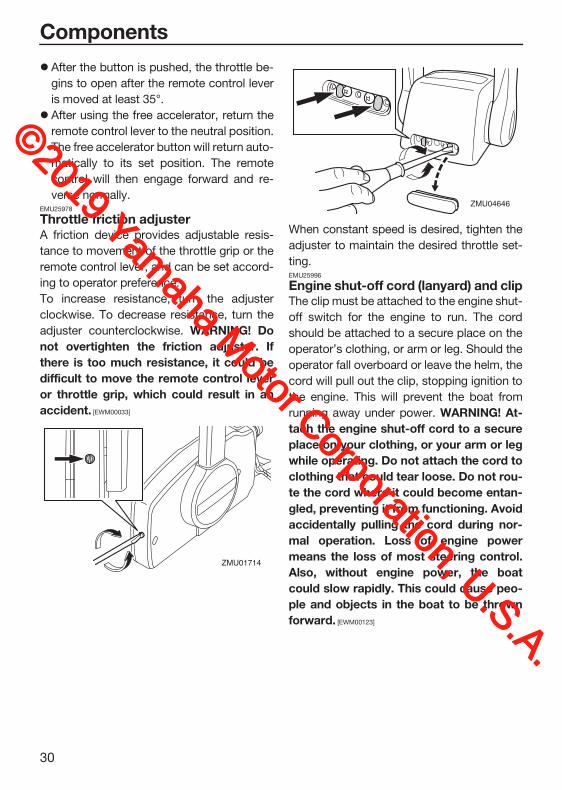
After the button is pushed, the throttle be-
gins to open after the remote control lever
is moved at least 35°.
After using the free accelerator, return the
remote control lever to the neutral position.
The free accelerator button will return auto-
matically to its set position. The remote
control will then engage forward and re-
verse normally.EMU25978
Throttle friction adjusterA friction device provides adjustable resis-
tance to movement of the throttle grip or the
remote control lever, and can be set accord-
ing to operator preference.
To increase resistance, turn the adjuster
clockwise. To decrease resistance, turn the
adjuster counterclockwise. WARNING! Donot overtighten the friction adjuster. Ifthere is too much resistance, it could bedifficult to move the remote control leveror throttle grip, which could result in anaccident. [EWM00033]
When constant speed is desired, tighten the
adjuster to maintain the desired throttle set-
ting.EMU25996
Engine shut-off cord (lanyard) and clipThe clip must be attached to the engine shut-
off switch for the engine to run. The cord
should be attached to a secure place on the
operator’s clothing, or arm or leg. Should the
operator fall overboard or leave the helm, the
cord will pull out the clip, stopping ignition to
the engine. This will prevent the boat from
running away under power. WARNING! At-tach the engine shut-off cord to a secureplace on your clothing, or your arm or legwhile operating. Do not attach the cord toclothing that could tear loose. Do not rou-te the cord where it could become entan-gled, preventing it from functioning. Avoidaccidentally pulling the cord during nor-mal operation. Loss of engine powermeans the loss of most steering control.Also, without engine power, the boatcould slow rapidly. This could cause peo-ple and objects in the boat to be thrownforward. [EWM00123]
ZMU01714
ZMU04646
©2019 Yamaha M
otor Corporation, U.S.A.

Components
31
EMU26092
Main switchThe main switch controls the ignition system;
its operation is described below.
“ ” (off)With the main switch in the “ ” (off) posi-
tion, the electrical circuits are off, and the key
can be removed.
“ ” (on)With the main switch in the “ ” (on) position,
the electrical circuits are on, and the key can-
not be removed.
“ ” (start)
With the main switch in the “ ” (start) po-
sition, the starter motor turns to start the en-
gine. When the key is released, it returns
automatically to the “ ” (on) position.
EMU32054
Power trim and tilt switch on remote controlThe power trim and tilt system adjusts the
outboard motor angle in relation to the tran-
som. Pushing the switch “ ” (up) trims the
outboard motor up, and then tilts it up. Push-
ing the switch “ ” (down) tilts the outboard
motor down and trims it down. When the
switch is released, the outboard motor will
stop in its current position. For instructions
on using the power trim and tilt switch, see
pages 64 and 66.
1. Engine shut-off cord (lanyard)
2. Clip
3. Engine shut-off switch
1. Engine shut-off cord (lanyard)
2. Clip
3. Engine shut-off switch
ZMU01716
12
3
ONSTARTOFF
ONSTARTOFF
1
2
3
ZMU05818
ON STARTOFF
ZMU01718
ONOFF START
ONOFF START
ZMU05821
©2019 Yamaha M
otor Corporation, U.S.A.

Components
32
EMU26156
Power trim and tilt switch on bottom cowlingThe power trim and tilt switch is located on
the side of the bottom cowling. Pushing the
switch “ ” (up) trims the outboard motor up,
and then tilts it up. Pushing the switch “ ”
(down) tilts the outboard motor down and
trims it down. When the switch is released,
the outboard motor will stop in its current po-
sition.
For instructions on using the power trim and
tilt switch, see page 66.
WARNINGEWM01032
Use the power trim and tilt switch locatedon the bottom cowling only when the boatis at a complete stop with the engine off.Attempting to use this switch while theboat is moving could increase the risk offalling overboard and could distract theoperator, increasing the risk of collisionwith another boat or an obstacle.
EMU26164
Power trim and tilt switches (twin bin-nacle type)The power trim and tilt system adjusts the
outboard motor angle in relation to the tran-
som. Pushing the switch “ ” (up) trims the
outboard motor up, and then tilts it up. Press-
ing the switch “ ” (down) tilts the outboard
motor down and trims it down. When the
switch is released, the outboard motor will
stop in its current position. For instructions
on using the power trim and tilt switches, see
pages 64 and 66.
TIP:On the dual engine control, the switch on the
remote control grip controls both outboard
motors at the same time.
DNUP
ZMU01720
1. Power trim and tilt switch
1. Power trim and tilt switch
1
UP
DN
ZMU07741
ZMU04601
DN
UP
1
©2019 Yamaha M
otor Corporation, U.S.A.

Components
33
EMU26246
Trim tab with anode
WARNINGEWM00841
An improperly adjusted trim tab couldcause difficult steering. Always test run af-ter the trim tab has been installed or re-placed to be sure steering is correct. Besure you have tightened the bolt after ad-justing the trim tab.
The trim tab should be adjusted so that the
steering control can be turned to either the
right or left by applying the same amount of
force.
If the boat tends to veer to the left (port side),
turn the trim tab rear end to the port side “A”
in the figure. If the boat tends to veer to the
right (starboard side), turn the trim tab end to
the starboard side “B” in the figure.
NOTICEECM00841
The trim tab also serves as an anode toprotect the engine from electrochemicalcorrosion. Never paint the trim tab as it willbecome ineffective as an anode.
EMU26342
Tilt support lever for power trim and tilt modelTo keep the outboard motor in the tilted up
position, lock the tilt support lever to the
clamp bracket.
NOTICEECM00661
Do not use the tilt support lever or knobwhen trailering the boat. The outboardmotor could shake loose from the tilt sup-port and fall. If the motor cannot betrailered in the normal running position,use an additional support device to secureit in the tilt position.
1. Cap
2. Bolt
3. Trim tab
3
21
ZMU07742
Bolt tightening torque:42 N·m (4.28 kgf·m, 31.0 lb·ft)
1. Tilt support lever
AB
ZMU07743
©2019 Yamaha M
otor Corporation, U.S.A.

Components
34
EMU40762
Cowling lock leverThe cowling lock levers are used to secure
the top cowling.
EMU26464
Flushing deviceThis device is used to clean the cooling water
passages of the motor using a garden hose
and tap water.
TIP:For details on usage, see page 73.EMU40823
Fuel filterThe fuel filter functions to remove foreign ma-
terial and separate water from the fuel. If wa-
ter separated from the fuel exceeds a specific
volume, the alert system will activate. For fur-
ther information, see page 49.
TIP:Adding an in-line 10-micron fuel filter has
been shown to greatly reduce the chance of
fuel contamination problems. Consult your
dealer for information about Yamaha 10-mi-
cron fuel filters if your boat does not have
one.
1. Cowling lock lever
1. Cowling lock lever
1ZMU07745
11
ZMU07746
1. Flushing device
1
ZMU07841
ZMU05493
©2019 Yamaha M
otor Corporation, U.S.A.
Instruments and indicators
35
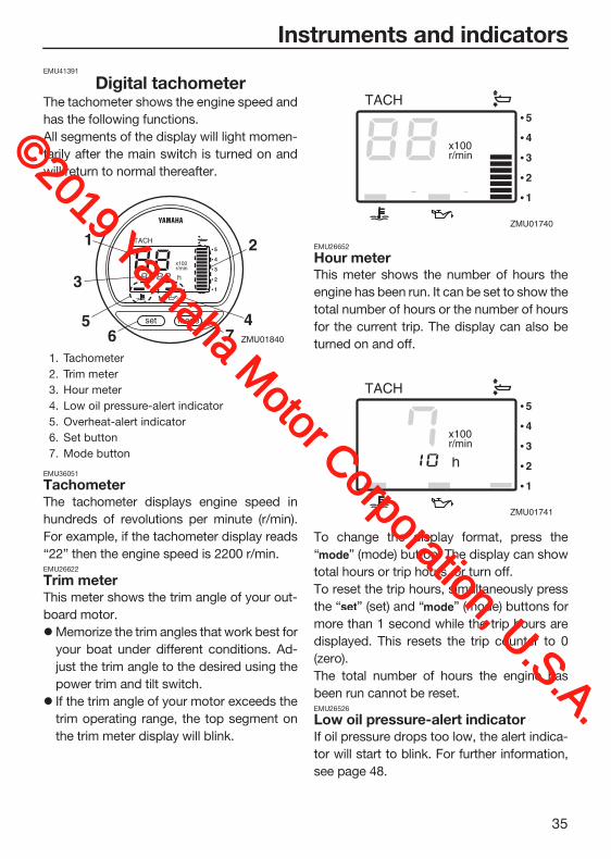
EMU41391
Digital tachometerThe tachometer shows the engine speed and
has the following functions.
All segments of the display will light momen-
tarily after the main switch is turned on and
will return to normal thereafter.
EMU36051
TachometerThe tachometer displays engine speed in
hundreds of revolutions per minute (r/min).
For example, if the tachometer display reads
“22” then the engine speed is 2200 r/min.EMU26622
Trim meterThis meter shows the trim angle of your out-
board motor.
Memorize the trim angles that work best for
your boat under different conditions. Ad-
just the trim angle to the desired using the
power trim and tilt switch.
If the trim angle of your motor exceeds the
trim operating range, the top segment on
the trim meter display will blink.
EMU26652
Hour meterThis meter shows the number of hours the
engine has been run. It can be set to show the
total number of hours or the number of hours
for the current trip. The display can also be
turned on and off.
To change the display format, press the
“ ” (mode) button. The display can show
total hours or trip hours, or turn off.
To reset the trip hours, simultaneously press
the “ ” (set) and “ ” (mode) buttons for
more than 1 second while the trip hours are
displayed. This resets the trip counter to 0
(zero).
The total number of hours the engine has
been run cannot be reset.EMU26526
Low oil pressure-alert indicatorIf oil pressure drops too low, the alert indica-
tor will start to blink. For further information,
see page 48.
1. Tachometer
2. Trim meter
3. Hour meter
4. Low oil pressure-alert indicator
5. Overheat-alert indicator
6. Set button
7. Mode button
ZMU01840
1
5
2
4
3
6 7
ZMU01740
ZMU01741
©2019 Yamaha M
otor Corporation, U.S.A.

Instruments and indicators
36
NOTICEECM00024
Do not continue to run the engine if thelow oil pressure-alert indicator is on andthe engine oil level is lower. Serious en-gine damage will occur.The low oil pressure-alert indicator doesnot indicate the engine oil level. Use theoil dipstick to check the oil level. For fur-ther information, see page 55.
EMU26584
Overheat-alert indicatorIf the engine temperature rises too high, the
alert indicator will start to blink. For further in-
formation on reading the indicator, see page
48.
NOTICEECM00053
Do not continue to run the engine if theoverheat-alert indicator is on. Serious en-gine damage will occur.
EMU26603
Digital speedometerThis gauge shows the boat speed and other
information.
All segments of the display will light momen-
tarily after the main switch is turned on and
will return to normal thereafter.EMU36062
SpeedometerThe speedometer displays km/h, mph, or
knots, according to operator preference. Se-
lect the desired units of measurement by set-
ting the selector switch on the back of the
gauge. See the illustration for settings.
1. Low oil pressure-alert indicator
ZMU017361
1. Overheat-alert indicator
1. Speedometer
2. Fuel gauge
3. Trip meter/clock/voltmeter
4. Alert indicator(s)
ZMU01737
1
TRIP TIME BATT
km/hknotmph
kmmile
SPEED
YAMAHA
set mode
12
43
ZMU07000
©2019 Yamaha M
otor Corporation, U.S.A.

Instruments and indicators
37
EMU26714
Fuel gaugeEight segments indicate the fuel level. When
all segments are showing, the fuel tank is full.
The fuel level reading can be inaccurate due
to the position of the sensor in the fuel tank
and the attitude of the boat in the water. Op-
eration with bow-up trim or continuous turn-
ing can give false readings.
Do not adjust the selector switch for fuel sen-
sor. Incorrectly setting the selector switch on
the gauge will give false readings. Consult
your Yamaha dealer on how to correctly set
the selector switch. NOTICE: Running out offuel can damage the engine. [ECM01771]
EMU36072
Trip meter / Clock / VoltmeterThe display shows either the trip meter, the
clock, or the voltmeter.
To change the display, press the “ ” (mo-
de) button repeatedly until the indicator on
the face of the gauge points to “ ” (trip
meter), “ ” (clock), or “ ” (voltmeter).EMU26692
Trip meterThis gauge displays the distance the boat has
traveled since the gauge was last reset.
The trip distance is shown in kilometers or
miles depending upon the unit of measure-
ment selected for the speedometer.
To reset the trip meter to zero, press the “ ”
(set) and “ ” (mode) buttons at the same
time.
The trip distance is kept in memory by battery
power. The stored data will be lost if the bat-
tery is disconnected.
EMU26702
ClockTo set the clock:
1. Be sure the gauge is in the “ ” (time)
mode.
2. Press the “ ” (set) button; the hour dis-
play will begin blinking.
3. Press the “ ” (mode) button until the
desired hour is displayed.
4. Press the “ ” (set) button again, the mi-
nute display will begin blinking.
5. Press the “ ” (mode) button until the
desired minute is displayed.
6. Press the “ ” (set) button again to start
the clock.
1. Cap
2. Selector switch (for speed unit)
3. Selector switch (for fuel sensor)
km/h(km)
mph(mile)
knots(mile)
12
34
ZMU07001
3
1
2
ZMU07002
TRIP TIME BATT
km/hknotmph
kmmile
SPEED
YAMAHA
set mode
ZMU07003
©2019 Yamaha M
otor Corporation, U.S.A.

Instruments and indicators
38
The clock operates on battery power. Dis-
connecting the battery will stop the clock.
Reset the clock after connecting the battery.EMU36081
VoltmeterThe voltmeter displays the charge of the bat-
tery in volts(V).EMU26723
Fuel level-alert indicatorIf the fuel level decreases to one segment, the
fuel level alert segment will blink.
Do not continue to operate the engine at full
throttle if an alert device has activated. Get
back to the port using trolling engine speed.
NOTICE: Running out of fuel can damagethe engine. [ECM01771]
EMU26733
Low battery voltage-alert indicatorIf battery voltage drops, the display will auto-
matically turn on and blink.
Get back to the port soon if an alert device
has activated. For charging the battery, con-
sult your Yamaha dealer.
EMU26742
Fuel management meterThe fuel management meter shows the state
of the fuel consumption while the engine is
running.
All segments of the display will light momen-
tarily after the main switch is turned on and
will return to normal thereafter.EMU26753
Fuel flow meterThe fuel flow meter displays the amount of
fuel flow over a one-hour period, at the cur-
rent rate of engine operation.
1. Fuel level-alert segment
TRIP TIME BATT
km/hknotmph
kmmile
SPEED
YAMAHA
set mode
ZMU07004
TRIP TIME BATT
km/hknotmph
kmmile
SPEED
YAMAHA
set mode
ZMU07005
1
1. Low battery indicator
1. Fuel flow meter
2. Fuel consumption meter / Fuel economy meter / Twin engine speed synchronizer
3. Water separator-alert indicator (operates only if the sensor has been installed)
TRIP TIME BATT
km/hknotmph
kmmile
SPEED
YAMAHA
set mode
ZMU07006
1
ZMU01748
1
23
©2019 Yamaha M
otor Corporation, U.S.A.

Instruments and indicators
39
The fuel flow meter displays gallons/hour
or liters/hour according to operator prefer-
ence. Select the desired units of measure-
ment by setting the selector switch on the
back of the gauge during installation.
The fuel consumption meter and fuel econ-
omy meter will indicate the same unit of
measurement.
Fuel flow readings are not accurate when the
engine is operating under about 1300 r/min.
As the fuel pump cycles on and off, the dis-
play indicates either no fuel flow or higher
flow than the actual average use.
Dual engine users: the fuel flow meter can
display the fuel flow of either or both engines.
To change the fuel flow display, press the
“ ” (set) button repeatedly until the gauge
displays “ ” (for fuel flow to the starboard en-
gine only), “ ” (for fuel flow to the port engine
only), or “ ” (for total fuel flow both en-
gines).EMU36091
Fuel consumption meter / Fuel econo-my meter / Twin engine speed syn-chronizerThe display shows either the fuel consump-
tion meter, the fuel economy meter, or the
twin engine synchronizer.
To change the display, press the “ ” (mo-
de) button repeatedly until the indicator on
the face of the gauge points to “ ” (fuel
consumption meter), “ ” (fuel economy
meter), or “ ” (twin engine speed syn-
chronizer).EMU26762
Fuel consumption meterThis gauge displays the total amount of fuel
consumed since the gauge was last reset.
To reset the total fuel consumption meter to
zero, press the “ ” (set) and “ ” (mode)
buttons at the same time.
EMU26772
Fuel economyThis gauge displays the approximate dis-
tance per liter or gallon when cruising.
1. Selector switch
ZMU01749
ZMU01751
©2019 Yamaha M
otor Corporation, U.S.A.

Instruments and indicators
40
If twin engines are installed on your boat, the
gauge will only display the total fuel economy
of both engines.
Fuel consumption varies greatly with boat
design, weight, propeller used, engine trim
angle, sea conditions (including wind), and
throttle position. Fuel consumption also
varies slightly with the type of water (salt,
fresh, and contaminate levels), air temper-
ature and humidity, cleanliness of the boat
bottom, engine mounting height, skill of the
operator, and individual gasoline formula-
tion (winter or summer fuel and amount of
additives).
The Yamaha digital speedometer and fuel
management meter calculates speed,
miles traveled, and fuel economy by water
movement at the stern of the boat. This dis-
tance can vary greatly from the actual dis-
tance traveled because of water currents,
sea swells, and the condition of the water
speed sensor (if partially plugged or dam-
aged).
Individual engines may slightly vary in their
fuel consumption due to manufacturing
variations. These variations can be even
greater if the engines are of different year
models. In addition, variations in propel-
lers, even of the same basic dimensions of
the same design, can also cause a slight
variation in fuel consumption.
EMU26783
Twin-engine speed synchronizerThis gauge displays the difference in engine
speed (r/min) between the port and starboard
engines for reference purposes when syn-
chronizing the two engines’ speeds.
If the two engines’ speeds are not synchro-
nized while cruising, adjusting trim angle or
throttle can synchronize them.
If large differences in trim angle or throttle are
needed to synchronize the engines, consult
your Yamaha dealer for adjustments to the
throttle cables.
ZMU01752
1. Port engine speed is higher
2. Port engine speed is slightly higher
3. Engine speed is synchronized evenly be-tween port and starboard engines
4. Starboard engine speed is slightly higher
5. Starboard engine speed is higher
ZMU01753
ZMU01754
1
2
3
4
5
©2019 Yamaha M
otor Corporation, U.S.A.

Instruments and indicators
41
EMU26794
Water separator-alert indicatorThis indicator will blink when water has accu-
mulated in the water separator. In such an
event, stop the engine and drain the water
from the separator.
This indicator only operates when a water
separator sensor is equipped.
EMU46662
6YC Multifunction meterThe 6YC Multifunction meter shows engine
status and alert information.
Multifunction display
TIP:The optional items displayed on the multi-
function display can be changed. For infor-
mation on other settings or changing the
displayed optional items, see the operation
manual included with the 6YC Multifunction
meter.
This manual mainly covers the alert display of
the 6YC Multifunction meter. See the follow-
ing sections for information about the display
and indicators.
Indicators
1. Multifunction display
2. Directional keypad
3. Set button
4. Cancel button
5. Menu button
ZMU01755
543
2
1
ZMU08323
1. Trim meter
2. Optional items
3. Tachometer
1. Yamaha Security System indicator (optional)
2. Engine trouble-alert indicator
3. Low battery voltage-alert indicator
4. Water separator-alert indicator
5. Low oil pressure-alert indicator
3
2
1
ZMU08324
6 5 4 3 2
1
ZMU08325
©2019 Yamaha M
otor Corporation, U.S.A.

Instruments and indicators
42
Yamaha Security System indicator (op-tional)This indicator appears, when the Yamaha Se-
curity System is in lock mode.
Make sure that the Yamaha Security System
indicator is off before starting the engine.
Engine trouble alertIf the engine malfunctions while cruising, the
pop-up window will appear.
To return to the normal display
Push the “SET” (set) button, and the engine
trouble-alert indicator will start to blink.
NOTICEECM00921
In such an event, the engine will not oper-ate properly. Consult a Yamaha dealer im-mediately.
Low battery voltage alertIf the battery voltage drops, the pop-up win-
dow will appear.
To return to the normal display
Push the “SET” (set) button, and the low bat-
tery voltage-alert indicator will start to blink.
6. Overheat-alert indicator
1. Yamaha Security System indicator (optional)
1. Pop-up window
1
ZMU08326
1
ZMU08327
1. Engine trouble-alert indicator
1. Pop-up window
1
ZMU08332
1
ZMU08328
©2019 Yamaha M
otor Corporation, U.S.A.

Instruments and indicators
43
Get back to the port soon if the low battery
voltage-alert device has activated. For charg-
ing the battery, consult your Yamaha dealer.
Water separator alertIf water has accumulated in the water sepa-
rator (fuel filter) while cruising, the pop-up
window will appear.
To return to the normal display
Push the “SET” (set) button, and the water
separator-alert indicator will start to blink.
Stop the engine immediately and see page
95 of this manual to drain the water from the
fuel filter. Get back to the port soon and con-
sult a Yamaha dealer immediately.
NOTICEECM00911
Gasoline mixed with water could causedamage to the engine.
Low oil pressure alertIf the engine oil pressure drops too low, the
pop -up window will appear.
The engine speed will automatically decrease
to about 2000–3500 r/min.
To return to the normal display
Push the “SET” (set) button, and the low oil
pressure-alert indicator will start to blink.
1. Low battery voltage-alert indicator
1. Pop-up window
1
ZMU08333
1
ZMU08329
1. Water separator-alert indicator
1. Pop-up window
1
ZMU08334
1
ZMU08330
©2019 Yamaha M
otor Corporation, U.S.A.
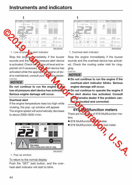
Instruments and indicators
44
Stop the engine immediately if the buzzer
sounds and the low oil pressure-alert device
is activated. Check the engine oil level and re-
plenish oil if necessary. If the alert device has
activated while the appropriate engine oil lev-
el is maintained, consult your Yamaha dealer.
NOTICEECM01602
Do not continue to run the engine if thelow oil pressure alert device has activated.Serious engine damage will occur.
Overheat alertIf the engine temperature rises too high while
cruising, the pop -up window will appear.
The engine speed will automatically decrease
to about 2000–3500 r/min.
To return to the normal display
Push the “SET” (set) button, and the over-
heat-alert indicator will start to blink.
Stop the engine immediately if the buzzer
sounds and the overheat device has activat-
ed. Check the cooling water inlet for clog-
ging.
NOTICEECM01594
Do not continue to run the engine if theoverheat-alert indicator blinks. Seriousengine damage will occur.Do not continue to operate the engine ifan alert device has activated. Consultyour Yamaha dealer if the problem can-not be located and corrected.
EMU46654
6Y8 Multifunction metersThere are two types of 6Y8 Multifunction me-
ters.
6Y8 Multifunction tachometer
6Y8 Multifunction speed & fuel meter
1. Low oil pressure-alert indicator
1. Pop-up window
1
ZMU08335
1
ZMU08331
1. Overheat-alert indicator
1
ZMU08336
©2019 Yamaha M
otor Corporation, U.S.A.

Instruments and indicators
45
6Y8 Multifunction tachometer
6Y8 Multifunction speed & fuel meter
TIP:The information displayed on the multifunc-
tion display can be changed. For information
on other settings or changing the displayed
information, see the operation manual includ-
ed with the 6Y8 Multifunction meter.
This manual mainly covers the alert display of
the 6Y8 Multifunction tachometer. See the
following sections for information about the
alert indicators.
Indicators
1. Set button
2. Mode button
1. Tachometer
2. Trim meter
3. Multifunction display
1. Set button
2. Mode button
SET MODE
21ZMU08407
1 2
3
ZMU08408
SET MODE
21ZMU08409
1. Speedometer
2. Fuel meter
3. Multifunction display
1. Yamaha Security System indicator (optional)
2. Water separator-alert indicator
3. Engine trouble-alert indicator
4. Battery voltage indicator
5. Overheat-alert indicator
6. Low oil pressure-alert indicator
1
3
2
ZMU08410
1
7 6 5 4
2 3
ZMU08411
©2019 Yamaha M
otor Corporation, U.S.A.
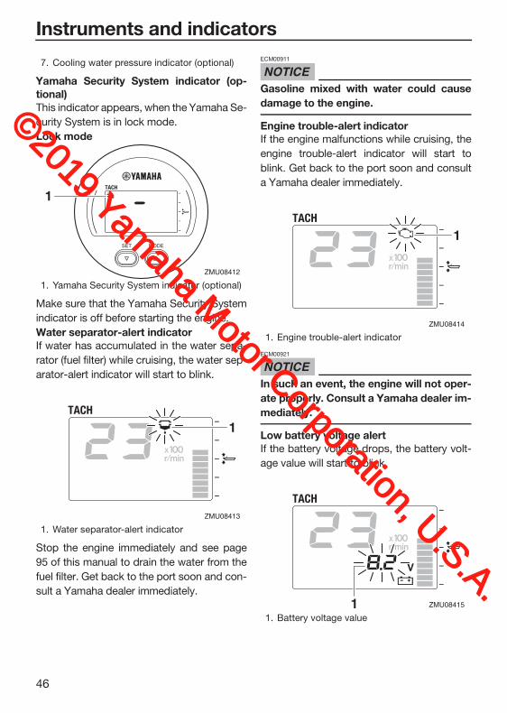
Instruments and indicators
46
Yamaha Security System indicator (op-tional)This indicator appears, when the Yamaha Se-
curity System is in lock mode.
Lock mode
Make sure that the Yamaha Security System
indicator is off before starting the engine.
Water separator-alert indicatorIf water has accumulated in the water sepa-
rator (fuel filter) while cruising, the water sep-
arator-alert indicator will start to blink.
Stop the engine immediately and see page
95 of this manual to drain the water from the
fuel filter. Get back to the port soon and con-
sult a Yamaha dealer immediately.
NOTICEECM00911
Gasoline mixed with water could causedamage to the engine.
Engine trouble-alert indicatorIf the engine malfunctions while cruising, the
engine trouble-alert indicator will start to
blink. Get back to the port soon and consult
a Yamaha dealer immediately.
NOTICEECM00921
In such an event, the engine will not oper-ate properly. Consult a Yamaha dealer im-mediately.
Low battery voltage alertIf the battery voltage drops, the battery volt-
age value will start to blink.
7. Cooling water pressure indicator (optional)
1. Yamaha Security System indicator (optional)
1. Water separator-alert indicator
SET MODE
1
ZMU08412
1
ZMU08413
1. Engine trouble-alert indicator
1. Battery voltage value
1
ZMU08414
1 ZMU08415
©2019 Yamaha M
otor Corporation, U.S.A.
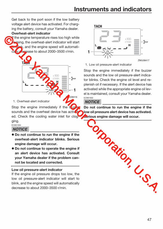
Instruments and indicators
47
Get back to the port soon if the low battery
voltage alert device has activated. For charg-
ing the battery, consult your Yamaha dealer.
Overheat-alert indicatorIf the engine temperature rises too high while
cruising, the overheat-alert indicator will start
to blink, and the engine speed will automati-
cally decrease to about 2000–3500 r/min.
Stop the engine immediately if the buzzer
sounds and the overheat device has activat-
ed. Check the cooling water inlet for clog-
ging.
NOTICEECM01594
Do not continue to run the engine if theoverheat-alert indicator blinks. Seriousengine damage will occur.Do not continue to operate the engine ifan alert device has activated. Consultyour Yamaha dealer if the problem can-not be located and corrected.
Low oil pressure-alert indicatorIf the engine oil pressure drops too low, the
low oil pressure-alert indicator will start to
blink, and the engine speed will automatically
decrease to about 2000–3500 r/min.
Stop the engine immediately if the buzzer
sounds and the low oil pressure-alert indica-
tor blinks. Check the engine oil level and re-
plenish oil if necessary. If the alert device has
activated while the appropriate engine oil lev-
el is maintained, consult your Yamaha dealer.
NOTICEECM01602
Do not continue to run the engine if thelow oil pressure alert device has activated.Serious engine damage will occur.
1. Overheat-alert indicator
1
ZMU08416
1. Low oil pressure-alert indicator
1
ZMU08417
©2019 Yamaha M
otor Corporation, U.S.A.

Engine control system
48
EMU26805
Alert system
NOTICEECM00093
Do not continue to operate the engine if analert device has activated. Consult yourYamaha dealer if the problem cannot belocated and corrected.
EMU41926
Overheat alertThis engine has an overheat-alert device. If
the engine temperature rises too high, the
alert device will activate.
The engine speed will automatically de-
crease to about 2000–3500 r/min.
The overheat-alert indicator will light or
blink.
The pop-up window will appear on the
Multi-Display.
The buzzer will sound.
If the alert system has activated, stop the en-
gine and check the cooling water inlets:
Check trim angle to be sure that the cooling
water inlet is submerged.
Check the cooling water inlet for clogging.
Twin engine drive users:
If the overheat alert system of one engine ac-
tivates, the engine will slow down. To switch
off the alert activation on the engine not af-
fected by overheating, turn off the main
switch of the engine overheating. If the alert
ZMU05422
ZMU08533
ZMU01758
ZMU07859
ZMU08288
©2019 Yamaha M
otor Corporation, U.S.A.

Engine control system
49
system has activated, stop the engine and tilt
the outboard motor up to check the cooling
water inlet for clogging. If the alert system has
still activated, tilt the overheated outboard
motor up and return to the port.EMU41936
Low oil pressure alertIf the oil pressure drops too low, the alert de-
vice will activate.
The engine speed will automatically de-
crease to about 2000–3500 r/min.
The low oil pressure-alert indicator will light
or blink.
The pop-up window will appear on the
Multi-Display.
The buzzer will sound.
If the alert device has activated, stop the en-
gine as soon as it is safe to do so. Check the
oil level and add oil as needed. If the oil level
is correct and the alert device does not
switch off, consult your Yamaha dealer.
Twin engine drive users:
If the low oil pressure alert system of one en-
gine activates, both engines will slow down
and the buzzer will sound. To switch off the
alert activation on the engine not affected by
low oil pressure, turn off the main switch of
the engine with the low oil pressure.EMU41946
Water separator alertThe outboard motor is equipped with a water
separator alert system. If water separated
from the fuel exceeds a specific volume, the
alert system will activate.
The water separator-alert indicator will
come on or blink.
ZMU05431
ZMU08534
ZMU01758
ZMU07859
©2019 Yamaha M
otor Corporation, U.S.A.

Engine control system
50
The pop-up window will appear on the
Multi-Display.
The buzzer will sound intermittently when
the control lever is in the neutral position.
If the alert system has activated, stop the en-
gine immediately and see page 95 of this
manual to drain the water from the fuel filter.
Get back to the port soon and consult a
Yamaha dealer immediately.
NOTICEECM02471
Although the buzzer will stop when the en-gine is started and the control lever ismoved to the forward or reverse position,do not use the outboard motor. Otherwise,serious engine damage could occur.
ZMU05424
ZMU08535
ZMU01758
ZMU07859
©2019 Yamaha M
otor Corporation, U.S.A.

Installation
51
EMU26903
InstallationThe information presented in this section is
intended as reference only. It is not possible
to provide complete instructions for every
possible boat and motor combination. Proper
mounting depends in part on experience and
the specific boat and motor combination.
WARNINGEWM01591
Overpowering a boat could cause se-vere instability. Do not install an out-board motor with more horsepowerthan the maximum rating on the capaci-ty plate of the boat. If the boat does nothave a capacity plate, consult the boatmanufacturer.Improper mounting of the outboard mo-tor could result in hazardous conditionssuch as poor handling, loss of control,or fire hazards. For permanently mount-ed models, your dealer or other personexperienced in proper rigging shouldmount the motor.
EMU33482
Mounting the outboard motorThe outboard motor should be mounted so
that the boat is well balanced. Otherwise, the
boat could be hard to steer. For single-engine
boats, mount the outboard motor on the cen-
terline (keel line) of the boat. For twin engine
boats, mount the outboard motors equidis-
tant from the centerline. Consult your
Yamaha dealer or boat manufacturer for fur-
ther information on determining the proper
mounting location.
EMU26936
Mounting height (boat bottom)The mounting height of your outboard motor
affects its efficiency and reliability. If it is
mounted too high, propeller ventilation may
occur, which will reduce propulsion due to
excessive propeller slip, and the water in-
takes for the cooling system may not get an
adequate water supply, which can cause en-
gine overheating. If the engine is mounted too
low, water resistance (drag) will increase,
thereby reducing engine efficiency and per-
formance.
Most commonly, outboard motor should be
mounted so that the anti-cavitation plate is in
alignment with the bottom of the boat. The
optimum mounting height of the outboard
motor is affected by the boat/motor combi-
nation and the desired use. Test runs at dif-
ferent heights can help determine the
1. Center line (keel line)
1. Center line (keel line)
ZMU017601
©2019 Yamaha M
otor Corporation, U.S.A.

Installation
52
optimum mounting height. Consult your
Yamaha dealer or boat manufacturer for fur-
ther information on determining the proper
mounting height.
NOTICEECM01635
Make sure that the idle hole is highenough to prevent water from enteringthe engine even if the boat is stationarywith the maximum load.Incorrect engine height or obstructionsto the smooth flow of water (such as thedesign or condition of the boat, or ac-cessories, such as transom ladders ordepth finder transducers) can create air-borne water spray while the boat iscruising. If the outboard motor is oper-ated continuously in the presence of air-borne water spray, enough water couldenter the engine through the air intakeopening in the top cowling to cause se-vere engine damage. Remove the causeof the airborne water spray.
ZMU01762
©2019 Yamaha M
otor Corporation, U.S.A.

Operation
53
EMU36382
First-time operationEMU36393
Fill engine oilThe engine is shipped from the factory with-
out engine oil. If your dealer did not fill the oil,
you must fill it before starting the engine.
NOTICE: Check that the engine is filledwith oil before first-time operation to avoidsevere engine damage. [ECM01782]
The engine is shipped with the following tag,
which should be removed after engine oil is
filled for the first time. For more information
on checking the engine oil level, see page 55.
EMU30175
Breaking in engineYour new engine requires a period of break-
in to allow mating surfaces of moving parts to
wear in evenly. Correct break-in will help en-
sure proper performance and longer engine
life. NOTICE: Failure to follow the break-inprocedure could result in reduced enginelife or even severe engine damage. [ECM00802]
EMU27086
Procedure for 4-stroke modelsYour new engine requires a period of 10
hours break-in to allow mating surfaces of
moving parts to wear in evenly.
TIP:Run the engine in the water, under load (in
gear with a propeller installed) as follows. For
10 hours for breaking in engine avoid extend-
ed idling, rough water and crowded areas.
1. For the first hour of operation:
Run the engine at varying speeds up to
2000 r/min or approximately half throttle.
2. For the second hour of operation:
Increase engine speed as much as nec-
essary to put the boat on plane (but
avoid full-throttle operation), then back
off on the throttle while keeping the boat
at a planing speed.
3. Remaining 8 hours:
Run the engine at any speed. However,
avoid operating at full throttle for more
than 5 minutes at a time.
4. After the first 10 hours:
Operate the engine normally.EMU36402
Getting to know your boatAll boats have unique handling characteris-
tics. Operate cautiously while you learn how
your boat handles under different conditions
and various trim angles (see page 64).EMU36414
Checks before starting engine
WARNINGEWM01922
If any item in “Checks before starting en-gine” is not working properly, have it in-spected and repaired before operating theoutboard motor. Otherwise, an accidentcould occur.
ZMU01710
©2019 Yamaha M
otor Corporation, U.S.A.

Operation
54
NOTICEECM00121
Do not start the engine out of water. Over-heating and serious engine damage canoccur.
EMU36422
Fuel levelBe sure you have plenty of fuel for your trip. A
good rule is to use 1/3 of your fuel to get to
the destination, 1/3 to return, and to keep 1/3
as an emergency reserve. With the boat level
on a trailer or in the water, turn the key to “ ”
(on) and check the fuel level. For fuel filling in-
structions, see page 59.EMU40774
Removing top cowlingFor the following checks, remove the top
cowling from the bottom cowling.
To remove the top cowling, pull the cowling
lock levers and lift up the top cowling.
EMU36443
Fuel system
WARNINGEWM00061
Gasoline and its vapors are highly flamma-ble and explosive. Keep away from sparks,cigarettes, flames, or other sources of ig-nition.
WARNINGEWM00911
Leaking fuel can result in fire or explosion.Check for fuel leakage regularly.If any fuel leakage is found, the fuel sys-tem must be repaired by a qualified me-chanic. Improper repairs can make theoutboard unsafe to operate.
EMU36453
Check for fuel leaksCheck for fuel leaks or gasoline fumes in
the boat.
Check for fuel leakage from the fuel sys-
tem.
Check the fuel tank and fuel lines for
cracks, swellings, or other damage.
1. Cowling lock lever
2. Bottom cowling
3. Top cowling
1
2
3
ZMU07749
1. Cowling lock lever
2. Bottom cowling
3. Top cowling
1
3
1
2
ZMU07750
©2019 Yamaha M
otor Corporation, U.S.A.
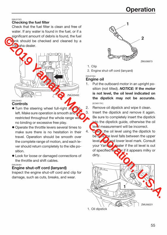
Operation
55
EMU37323
Checking the fuel filterCheck that the fuel filter is clean and free of
water. If any water is found in the fuel, or if a
significant amount of debris is found, the fuel
tank should be checked and cleaned by a
Yamaha dealer.
EMU36463
ControlsTurn the steering wheel full-right and full-
left. Make sure operation is smooth and un-
restricted throughout the whole range with
no binding or excessive free play.
Operate the throttle levers several times to
make sure there is no hesitation in their
travel. Operation should be smooth over
the complete range of motion, and each le-
ver should return completely to the idle po-
sition.
Look for loose or damaged connections of
the throttle and shift cables.EMU36484
Engine shut-off cord (lanyard)Inspect the engine shut-off cord and clip for
damage, such as cuts, breaks, and wear.
EMU37054
Engine oil1. Put the outboard motor in an upright po-
sition (not tilted). NOTICE: If the motoris not level, the oil level indicated onthe dipstick may not be accurate.[ECM01791]
2. Remove oil dipstick and wipe it clean.
3. Insert the dipstick and remove it again.
Be sure to completely insert the dipstick
into the dipstick guide, otherwise the oil
level measurement will be incorrect.
4. Check the oil level using the dipstick to
be sure the level falls between the upper
level mark and lower level mark. Consult
your Yamaha dealer if the oil level is out
of specified level or if it appears milky or
dirty.
ZMU05493
1. Clip
2. Engine shut-off cord (lanyard)
1. Oil dipstick
ZMU06873
1
2
1
ZMU06221
©2019 Yamaha M
otor Corporation, U.S.A.

Operation
56
EMU27154
EngineCheck the engine and engine mounting.
Look for loose or damaged fasteners.
Check the propeller for damage.
Check for engine oil leaks.EMU36494
Flushing deviceCheck that the flushing device’s garden hose
connector is securely screwed on to the fit-
ting on the bottom cowling. NOTICE: If thegarden hose connector is not properlyconnected, cooling water can leak out andthe engine can overheat during operation.[ECM01802]
EMU40752
Installing top cowling1. Check the rubber seal for damage. If the
rubber seal is damaged, have it replaced
by a Yamaha dealer.
2. Check that the rubber seal is seated all
the way around the bottom cowling.
3. Check that all of the cowling lock levers
are pulled outward.
4. Align the 3 protrusions on the top cowl-
ing with the corresponding holders on
the bottom cowling, and then place the
top cowling on the bottom cowling.
1. Oil dipstick
2. Lower mark
3. Upper mark
1. Fitting
2. Garden hose connector
3. Flushing device
1 3
2
ZMU07056
3 2 1
ZMU07754
1. Rubber seal
2. Bottom cowling
1. Top cowling
2. Protrusion
3. Holder
4. Bottom cowling
1
2ZMU08260
2
31
4ZMU07756
©2019 Yamaha M
otor Corporation, U.S.A.

Operation
57
5. Push the cowling lock levers inward to
secure the top cowling.
6. Check the fitting of the top cowling by
pushing it with both hands. NOTICE: Ifthe top cowling is not installed cor-
rectly, water can enter the top cowlingand damage the engine, or the topcowling can blow off at high speeds.[ECM02371]
EMU2915A
Checking power trim and tilt system
WARNINGEWM01931
Never get under the lower unit while it istilted, even when the tilt support lever islocked. Severe injury could occur if theoutboard motor accidentally falls.Body parts can be crushed between themotor and the clamp bracket when themotor is trimmed or tilted.Be sure no one is near the outboard mo-tor before performing this check.
1. Check the power trim and tilt unit for any
sign of oil leaks.
2. Operate each of the power trim and tilt
switches on the remote control and en-
gine bottom cowling to check that all
switches work.
3. Tilt the outboard motor up and check
that the tilt rod and trim rods are extend-
ed completely.
1. Top cowling
2. Protrusion
3. Holder
4. Bottom cowling
1. Cowling lock lever
1. Cowling lock lever
1
23
23
4
ZMU07757
1 ZMU07758
11
ZMU07759
ZMU07760
©2019 Yamaha M
otor Corporation, U.S.A.

Operation
58
4. Use the tilt support lever to lock the mo-
tor in the up position. Operate the tilt
down switch briefly so the motor is sup-
ported by the tilt support lever.
5. Check that the tilt rod and trim rods are
free of corrosion or other flaws.
6. Activate the tilt-down switch until the
trim rods have retracted completely into
the cylinders.
7. Activate the trim-up switch until the tilt
rod is fully extended. Unlock the tilt sup-
port lever.
8. Tilt the outboard motor down. Check
that the tilt rod and trim rods operate
smoothly.EMU36585
BatteryCheck the battery’s charge. If your boat is
equipped with a Yamaha digital speedome-
ter, the voltmeter and low battery alert func-
tions will help you monitor the battery’s
charge. A battery in good condition will pro-
vide a minimum of 12 volts. Check that the
battery connections are clean, secure and
covered by insulating covers. The electrical
connections of the battery and cables must
be clean and properly connected or the bat-
tery will not start the engine.
If the battery needs charging, consult your
Yamaha dealer or the battery manufacturer’s
instructions.
1. Tilt rod
2. Trim rod
1. Tilt support lever
ZMU03458
1
2
1
ZMU07380
ZMU03452
ZMU02635
©2019 Yamaha M
otor Corporation, U.S.A.

Operation
59
EMU30027
Filling fuel
WARNINGEWM01831
Gasoline and its vapors are highly flam-mable and explosive. Always refuel ac-cording to this procedure to reduce therisk of fire and explosion.Gasoline is poisonous and can cause in-jury or death. Handle gasoline with care.Never siphon gasoline by mouth. If youshould swallow some gasoline or inhalea lot of gasoline vapor, or get some gas-oline in your eyes, see your doctor im-mediately. If gasoline spills on your skin,wash with soap and water. If gasolinespills on your clothing, change yourclothes.
1. Make sure that the engine is stopped.
2. Make sure that the boat is in a well-ven-
tilated outdoor area, either securely
moored or trailered.
3. Make sure that no one is in the boat.
4. Do not smoke and keep away from
sparks, flames, static electric discharge,
or other sources of ignition.
5. If you use a portable container to store
and dispense fuel, only use a locally ap-
proved GASOLINE container.
6. Touch the fuel nozzle to the filler opening
or funnel to help prevent electrostatic
sparks.
7. Fill the fuel tank, but do not overfill.
WARNING! Do not overfill. Otherwisefuel can expand and overflow if thetemperature increases. [EWM02611]
8. Tighten the fuel tank cap securely.
9. Wipe up any spilled gasoline immediate-
ly with dry rags. Dispose of rags properly
according to local laws or regulations.
EMU27453
Operating engine
WARNINGEWM00421
Before starting the engine, make surethat the boat is tightly moored and thatyou can steer clear of any obstructions.Be sure there are no swimmers in thewater near you.When the air vent screw is loosened,gasoline vapor will be released. Gaso-line is highly flammable, and its vaporsare flammable and explosive. Refrainfrom smoking, and keep away fromopen flames and sparks while looseningthe air vent screw.This product emits exhaust gases whichcontain carbon monoxide, a colorless,odorless gas which could cause braindamage or death when inhaled. Symp-toms include nausea, dizziness, anddrowsiness. Keep cockpit and cabin ar-eas well ventilated. Avoid blocking ex-haust outlets.
EMU31814
Sending fuel1. If there is a fuel joint or a fuel valve on the
boat, firmly connect the fuel line to the
joint or open the fuel valve.
2. Squeeze the primer pump, with the ar-
row pointing up, until you feel it become
firm.
©2019 Yamaha M
otor Corporation, U.S.A.

Operation
60
EMU27495
Starting engine
WARNINGEWM01601
Before starting the engine, make sure thatthe boat is tightly moored and that you cansteer clear of any obstructions. Be surethere are no swimmers in the water nearyou.
EMU2762B
Electric start and remote control models
WARNINGEWM01842
Failure to attach the engine shut-offcord could result in a runaway boat ifoperator is ejected. Attach the engineshut-off cord to a secure place on yourclothing, or your arm or leg while oper-ating. Do not attach the cord to clothingthat could tear loose. Do not route thecord where it could become entangled,preventing it from functioning.Avoid accidentally pulling the cord dur-ing normal operation. Loss of enginepower means the loss of most steeringcontrol. Also, without engine power, theboat could slow rapidly. This could cau-se people and objects in the boat to bethrown forward.
1. Place the remote control lever in “ ”
(neutral).
TIP:The start-in-gear protection device prevents
the engine from starting except when in neu-
tral.
2. Attach the engine shut-off cord to a se-
cure place on your clothing, or your arm
or leg. Then install the clip on the other
end of the cord into the engine shut-off
switch.
1. Arrow
N
ZMU01771
N
ZMU04588
ZMU01772
©2019 Yamaha M
otor Corporation, U.S.A.

Operation
61
3. Turn the main switch to “ ” (on).
TIP:Dual engine users: When the main switch is
turned on, the buzzer operates for a few sec-
onds then stops automatically. The buzzer
also operates if one of the engines stalls.
4. Turn the main switch to “ ” (start),
and hold it for a maximum of 5 seconds.
5. Immediately after the engine starts, re-
lease the main switch to return it to “ ”
(on). NOTICE: Never turn the mainswitch to “ ” (start) while the en-gine is running. Do not keep the start-er motor turning for more than 5seconds. If the starter motor is turnedcontinuously for more than 5 seconds,the battery will be quickly discharged,thus making it impossible to start theengine. The starter can also be dam-aged. If the engine will not start after 5seconds of cranking, return the mainswitch to “ ” (on), wait 10 seconds,then crank the engine again. [ECM00193]
EMU36511
Checks after starting engineEMU36524
Cooling waterCheck for a steady flow of water from the
cooling water pilot hole. A continuous flow of
water from the pilot hole indicates that the
water pump is pumping water through the
cooling water passages. If the cooling water
passages are frozen, it may take a while for
water to start flowing out of the pilot hole.
NOTICEECM01811
If water is not flowing out of the pilot holeat all times while the engine is running,overheating and serious damage couldoccur. Stop the engine and check whether
ONSTARTOFF
ONSTARTOFF
ZMU05828
ONSTART
ZMU01774
ONSTART
ZMU05830
©2019 Yamaha M
otor Corporation, U.S.A.

Operation
62
the cooling water inlet on the lower caseor the cooling water pilot hole is blocked.Consult your Yamaha dealer if the prob-lem cannot be located and corrected.
EMU27671
Warming up engineEMU41234
Procedure for warming up engine1. After starting the engine, warm up the
engine until the engine speed stabilizes
at idle speed to provide maximum oper-
ating performance and acceleration.
NOTICE: Failure to do so will shortenengine life. [ECM04550]
2. Check that the low oil pressure-alert indi-
cator remains off. NOTICE: If the low oilpressure-alert indicator blinks afterthe engine starts, stop the engine.Otherwise, serious engine damagecould occur. Consult your Yamahadealer. [ECM02381]
EMU36532
Checks after engine warm upEMU36542
ShiftingWhile the boat is tightly moored, and without
applying throttle, confirm that the engine
shifts smoothly into forward and reverse, and
back to neutral.EMU40461
Stop switchesPerform the following procedure to check
that the main switch and engine shut-off
switch operate properly.
Check that the engine stops when the main
switch is turned to the “ ” (off) position.
Check that the engine stops when the clip
is pulled from the engine shut-off switch.
Check that the engine cannot be started
with the clip removed from the engine shut-
off switch.EMU31734
Shifting
WARNINGEWM00181
Before shifting, make sure there are noswimmers or obstacles in the water nearyou.
NOTICEECM01611
Warm up the engine before shifting intogear. Until the engine is warm, the idlespeed may be higher than normal. Highidle speed can prevent you from shiftingback to neutral. If this occurs, stop the en-gine, shift to neutral, then restart the en-gine and allow it to warm up.
To shift out of neutral
1. Pull the neutral interlock trigger up (if
equipped).
1. Cooling water pilot hole
Idle speed (in neutral):650–750 r/min
1
ZMU07766
©2019 Yamaha M
otor Corporation, U.S.A.

Operation
63
2. Move the remote control lever firmly and
crisply forward (for forward gear) or rear-
ward (for reverse gear) about 35° (a de-
tent can be felt).
To shift from in gear (forward/reverse) to neu-
tral
1. Close the throttle so that the engine
slows to idle speed.
2. After the engine is at idle speed in gear,
move the remote control lever firmly and
crisply to the neutral position.
1. Neutral interlock trigger
1
ZMU01727
FN
R32˚ 32˚
ZMU05460
RF
ZMU05462
N
ZMU01771
©2019 Yamaha M
otor Corporation, U.S.A.

Operation
64
EMU31743
Stopping boat
WARNINGEWM01511
Do not use the reverse function to slowdown or stop the boat as it could causeyou to lose control, be ejected, or im-pact the steering wheel or other parts ofthe boat. This could increase the risk ofserious injury. It could also damage theshift mechanism.Do not shift into reverse while travelingat planing speeds. Loss of control, boatswamping, or damage to the boat couldoccur.
The boat is not equipped with a separate
braking system. Water resistance stops it af-
ter the throttle lever is moved back to idle.
The stopping distance varies depending on
gross weight, water surface conditions, and
wind direction.EMU27822
Stopping engineBefore stopping the engine, first let it cool off
for a few minutes at idle or low speed. Stop-
ping the engine immediately after operating
at high speed is not recommended.EMU31832
Procedure1. Turn the main switch to “ ” (off).
2. Remove the key if the boat will be left un-
attended.
TIP:The engine can also be stopped by pulling
the cord and removing the clip from the en-
gine shut-off switch, then turning the main
switch to “ ” (off).EMU27865
Trimming outboard motor
WARNINGEWM00741
Excessive trim for the operating condi-tions (either trim up or trim down) can cau-se boat instability and can make steeringthe boat more difficult. This increases thepossibility of an accident. If the boat be-gins to feel unstable or is hard to steer,slow down and/or readjust the trim angle.
The trim angle of the outboard motor helps
determine the position of the bow of the boat
in the water. Correct trim angle will help im-
N
ZMU04588
ONOFF
ZMU01779
OFFOFFON ON
ZMU05833
©2019 Yamaha M
otor Corporation, U.S.A.

Operation
65
prove performance and fuel economy while
reducing strain on the engine. Correct trim
angle depends upon the combination of
boat, engine, and propeller. Correct trim is
also affected by variables such as the load in
the boat, sea conditions, and running speed.
EMU27889
Adjusting trim angle (Power trim and tilt)
WARNINGEWM00754
Be sure all people are clear of the out-board motor when adjusting the trim an-gle. Body parts can be crushed betweenthe motor and the clamp bracket whenthe motor is trimmed or tilted.Use caution when trying a trim positionfor the first time. Increase speed gradu-ally and watch for any signs of instabilityor control problems. Improper trim an-gle can cause loss of control.If equipped with a power trim and tiltswitch located on the bottom cowling,use the switch only when the boat is at acomplete stop with the engine off. Donot adjust the trim angle with this switchwhile the boat is moving.
Adjust the outboard motor trim angle using
the power trim and tilt switch.
To raise the bow (trim-out), press the switch
“ ” (up).
To lower the bow (trim-in), press the switch
“ ” (down).
Make test runs with the trim set to different
angles to find the position that works best for
your boat and operating conditions.EMU27913
Adjusting boat trimWhen the boat is on plane, a bow-up attitude
results in less drag, greater stability and effi-
ciency. This is generally when the keel line of
the boat is up about 3 to 5 degrees. With the
bow up, the boat may have a greater tenden-
cy to steer to one side or the other. Compen-
sate for this as you steer. When the bow of
the boat is down, it is easier to accelerate
from a standing start onto plane.
1. Trim operating angle
1. Power trim and tilt switch
1. Power trim and tilt switch
DNUP
1
ZMU01781
DN
UP
1
ZMU07381
©2019 Yamaha M
otor Corporation, U.S.A.

Operation
66
Bow UpToo much trim-out puts the bow of the boat
too high in the water. Performance and econ-
omy are decreased because the hull of the
boat is pushing the water and there is more
air drag. Excessive trim-out can also cause
the propeller to ventilate, which reduces per-
formance further, and the boat may “por-
poise” (hop in the water), which could throw
the operator and passengers overboard.
Bow DownToo much trim-in causes the boat to “plow”
through the water, decreasing fuel economy
and making it hard to increase speed. Oper-
ating with excessive trim-in at higher speeds
also makes the boat unstable. Resistance at
the bow is greatly increased, heightening the
danger of “bow steering” and making opera-
tion difficult and dangerous.
TIP:Depending on the type of boat, the outboard
motor trim angle may have little effect on the
trim of the boat when operating.EMU27936
Tilting up and downIf the engine will be stopped for some time or
if the boat is moored in shallows, the out-
board motor should be tilted up to protect the
propeller and lower casing from damage by
collision with obstructions, and also to re-
duce salt corrosion.
WARNINGEWM00223
Make sure that no one is near the out-board motor when tilting the outboardmotor up or down. Otherwise, body partscould be crushed between the outboardmotor and the clamp bracket.
WARNINGEWM00251
Leaking fuel is a fire hazard. If there is afuel joint on the outboard motor, discon-nect the fuel line or close the fuel cock ifthe engine will be tilted for more than afew minutes. Otherwise fuel may leak.
©2019 Yamaha M
otor Corporation, U.S.A.

Operation
67
NOTICEECM00242
Before tilting the outboard motor, stopthe engine by following the procedureon page 64. Never tilt the outboard mo-tor while the engine is running. Severedamage from overheating can result.Do not tilt up the engine by pushing thetiller handle (if equipped) because thiscould break the handle.
EMU42683
Procedure for tilting up1. Place the remote control lever in neutral.
2. Press the power trim and tilt switch “ ”
(up) until the outboard motor has tilted
up completely.
3. Pull the tilt support lever toward you to
support the engine. WARNING! Aftertilting the outboard motor, be sure tosupport it with the tilt support knob ortilt support lever. Otherwise the out-board motor could fall back downsuddenly if oil in the power trim and tiltunit or in the power tilt unit loses pres-
N
ZMU01771
N
ZMU07382
1. Power trim and tilt switch
1. Power trim and tilt switch
1. Power trim and tilt switch
ZMU07848
UP
1
ZMU07850
UP1
1
UP
ZMU07768
©2019 Yamaha M
otor Corporation, U.S.A.

Operation
68
sure. [EWM00263] NOTICE: Do not use thetilt support lever or knob when traile-ring the boat. The outboard motorcould shake loose from the tilt supportand fall. If the motor cannot betrailered in the normal running posi-tion, use an additional support deviceto secure it in the tilt position. Formore detailed information, see page71. [ECM01642]
4. Once the outboard motor is supported
with the tilt support lever, press the pow-
er trim and tilt switch “ ” (down) to re-
tract the trim rods. NOTICE: Make surethat the trim rods retracts completelyduring mooring. This protects the rodsfrom marine growth and corrosion,which could damage the power trimand tilt mechanism. [ECM00253]
EMU42702
Procedure for tilting down1. Push the power trim and tilt switch “ ”
(up) until the outboard motor is support-
ed by the tilt rod and the tilt support lever
becomes free.
2. Release the tilt support lever.
3. Push the power trim and tilt switch “ ”
(down) to lower the outboard motor to
the desired position.
ZMU07385
1. Power trim and tilt switch
ZMU07851
1
DN
©2019 Yamaha M
otor Corporation, U.S.A.

Operation
69
EMU28063
Shallow water EMU40702
Cruising in shallow waterThe outboard motor can be tilted up partially
to allow operation in shallow water.
NOTICEECM02361
Do not tilt the outboard motor up so thatthe cooling water inlet on the lower unit isabove the surface of the water when set-ting up for and cruising in shallow water.Otherwise severe damage from overheat-ing can result.
EMU32923
Procedure for power trim and tilt models1. Place the remote control lever in neutral.
2. Slightly tilt the outboard motor up to the
desired position using the power trim
and tilt switch. WARNING! Using thepower trim and tilt switch on the bot-tom cowling while the boat is movingor engine is on could increase the riskof falling overboard and could distract
1. Power trim and tilt switch
1. Power trim and tilt switch
ZMU07853
DN
1
1DN
ZMU07771
1. Cooling water inlet
1
ZMU07772
N
ZMU01771
N
ZMU04588
©2019 Yamaha M
otor Corporation, U.S.A.

Operation
70
the operator, increasing the risk ofcollision with another boat or an ob-stacle. [EWM01851]
3. To return the outboard motor to the nor-
mal running position, press the power
trim and tilt switch and slowly tilt the out-
board motor down.EMU41371
Operating in other conditionsOperating in salt waterAfter operating in saltwater, brackish water,
or water high in other minerals, flush the cool-
ing system with fresh water to minimize cor-
rosion and clogging of the cooling water
passages with deposits. Also, rinse the exte-
rior of the outboard motor with fresh water.
Operating in water containing mud, sand,silt, debris, or vegetationMud, sand, silt, debris, and vegetation in the
water may restrict water flow into the cooling
water inlet covers or clog internal water pas-
sages. Check and clean the cooling water in-
let covers frequently when operating in these
conditions. Flush the engine with clean, fresh
water after use in these environments. Con-
sult your dealer if normal water flow can not
be restored by cleaning the cooling water in-
let covers or flushing with fresh water.
©2019 Yamaha M
otor Corporation, U.S.A.

Maintenance
71
EMU41532
Transporting and storing out-board motor
WARNINGEWM02641
USE CARE when transporting fuel tank,whether in a boat or car.DO NOT fill fuel container to maximumcapacity. Gasoline will expand consider-ably as it warms up and can build uppressure in the fuel container. This cancause fuel leakage and a potential firehazard.Leaking fuel is a fire hazard. Tighten se-curely the fuel valve when transportingand storing the outboard motor.Never get under the outboard motorwhile it is tilted. Severe injury could oc-cur if the outboard motor accidentallyfalls.Do not use the tilt support lever or knobwhen trailering the boat. The outboardmotor could shake loose from the tiltsupport and fall. If the outboard motorcannot be trailered in the normal run-ning position, use an additional supportdevice to secure it in the tilt position.
Leaking fuel is a fire hazard. When trailering
the boat, close the fuel valve to prevent fuel
from leaking.
The outboard motor should be transported
and stored in the normal running position. If
there is insufficient road clearance in this po-
sition, then trailer the outboard motor in the
tilt position using a motor support device
such as a transom saver bar. Consult your
Yamaha dealer for further details.
When the outboard motor is tilted prolonged
time for mooring or trailering the boat, close
the fuel valve.
EMU30062
Storing outboard motorWhen storing your Yamaha outboard motor
for prolonged periods of time (2 months or
longer), several important procedures must
be performed to prevent excessive damage.
It is advisable to have your outboard motor
serviced by an authorized Yamaha dealer pri-
or to storage. However, you, the owner, with
a minimum of tools, can perform the follow-
ing procedures.
NOTICEECM01361
To prevent problems which can becaused by oil entering the cylinder fromthe sump, keep the outboard motor inthe attitude shown when transportingand storing it. Do not store or transportthe outboard motor on its side (not up-right).Do not place the outboard motor on itsside before the cooling water hasdrained from it completely, otherwisewater may enter the cylinder through theexhaust port and cause engine trouble.Store the outboard motor in a dry, well-ventilated place, not in direct sunlight.
EMU41382
Conditioning and stabilizing gasolineWhen preparing to store a boat for extended
periods (2 months or longer) it is best to com-
pletely remove all gasoline from the boat’s
fuel tank(s). If it is not possible to remove the
gasoline, add one ounce of “Yamalube Fuel
Stabilizer & Conditioner Plus” to each gallon
of gasoline in a full tank of gasoline to provide
fuel stability and corrosion protection.
©2019 Yamaha M
otor Corporation, U.S.A.

Maintenance
72
TIP:Do not fill the fuel tank(s) to the point of over-
flowing. Approximately 7/8 full will allow
enough space in the fuel tank to prevent gas-
oline purging from the fuel tank vent due to
expansion with temperature changes.
Do not cap the fuel tank vent. Excessive
pressure could damage the boat and motor’s
fuel systems.
A partially filled fuel tank, less than 7/8 full but
not completely empty, is not recommended.
Air space above the gasoline allows air
movement which can bring in water through
condensation as the air temperature chang-
es.
Condensation inside the fuel tank can cause
corrosion problems and phase separation of
gasoline containing ethanol.
Consult your Yamaha dealer concerning pre-
ventative measures that may work best for
the gasoline and environmental conditions in
your area.EMU28306
ProcedureEMU44313
Flushing with the flushing attachment Cooling system flushing is essential to pre-
vent the cooling system from clogging up
with salt, sand, or dirt. In addition, fogging/lu-
bricating of the engine is mandatory to pre-
vent excessive engine damage due to rust.
Perform the flushing and fogging at the same
time.
1. Wash the exterior of the outboard motor
using fresh water. NOTICE: Do notspray water into the air intake. [ECM01841]
For further information, see page 74.
2. Fill the fuel tank with fresh fuel and add
one ounce of “Yamalube Fuel Stabilizer
& Conditioner Plus” to each gallon of fu-
el.
TIP:The use of “Yamalube Fuel Stabilizer & Con-
ditioner Plus” eliminates the need to drain the
fuel system. Consult your Yamaha dealer or
other qualified mechanic if the fuel system is
to be drained instead.
3. Remove the top cowling and propeller.
4. Install the flushing attachment over the
cooling water inlet, and then turn on the
water supply. NOTICE: Do not run theengine without supplying it with cool-ing water. Either the engine waterpump will be damaged or the enginewill be damaged from overheating.Before starting the engine, be sure tosupply water to the cooling water pas-sages. Avoid running the outboardmotor at high speed while on theflushing attachment, otherwise over-heating could occur. [ECM02001]
TIP:A flushing attachment is available from your
Yamaha dealer.
5. Run the engine at a fast idle for a few mi-
nutes in neutral while supplying fresh wa-
ter. WARNING! Do not touch orremove electrical parts when startingor during operation. Keep hands, hair,
1. Flushing attachment
1
ZMU08002
©2019 Yamaha M
otor Corporation, U.S.A.

Maintenance
73
and clothes away from the flywheeland other rotating parts while the en-gine is running. [EWM00092]
TIP:When using the flushing attachment, main-
tain adequate water pressure so that there
is a steady flow of water from the cooling
water pilot hole.
If the overheat alert device is activated, turn
the engine off, and consult your Yamaha
dealer.
6. Just prior to turning off the engine, quick-
ly spray “Yamaha Stor-Rite Engine Fog-
ging Oil” into the intake silencer. When
properly done, the engine will smoke ex-
cessively and almost stall.
7. Turn off the water supply, and then re-
move the flushing attachment and wipe
off any excess water.
8. Install the top cowling and propeller.
9. Drain the cooling water completely out of
the outboard motor. Clean the exterior of
the outboard motor thoroughly.EMU41072
Lubrication1. Change the gear oil. For instructions, see
page 86. Check the gear oil for the pres-
ence of water that indicates a leaky seal.
Seal replacement should be performed
by an authorized Yamaha dealer prior to
use.
2. Lubricate all grease fittings. For further
details, see page 79.
TIP:For long-term storage, fogging the engine
with fogging oil is recommended. Contact
your Yamaha dealer for information about
fogging oil and procedures for your outboard
motor.EMU30268
Cleaning and anticorrosion measures1. Wash down the exterior of the outboard
motor with fresh water and dry off com-
pletely. NOTICE: Do not spray waterinto the air intake. [ECM01841] For further in-
formation, see page 74.
2. Spray the outboard motor exterior with
“Yamaha Silicone Protectant”. NOTICE:Do not spray when the engine is run-ning. Also, do not spray near the si-lencer or into the engine. Otherwisethe engine could be damaged. [ECM01403]
3. Wax the cowling with a non-abrasive
wax such as “Yamaha Silicone Wax”.EMU40964
Flushing cooling water passagePerform this procedure right after operation
for the most thorough flushing.
NOTICEECM01531
Do not perform this procedure while theengine is running. The water pump may bedamaged and severe damage from over-heating can result.
1. Disconnect the garden hose connector
from the fitting on the bottom cowling.
ZMU08155
©2019 Yamaha M
otor Corporation, U.S.A.

Maintenance
74
2. Connect the garden hose to the garden
hose connector.
3. With the engine off, turn on the water
supply and let the water flush through
the cooling water passages for about 15
minutes.
4. Turn off the water supply, and then dis-
connect the garden hose from the gar-
den hose connector.
5. Connect the garden hose connector to
the fitting on the bottom cowling and
tighten it securely. NOTICE: If the gar-den hose connector is not properly
connected, cooling water can leak outand the engine can overheat duringoperation. [ECM01802]
TIP:When flushing the cooling water passages
with the boat in the water, tilting the outboard
motor up until it is completely out of the water
will achieve better results.EMU44342
Cleaning the outboard motorWhen cleaning the outboard motor, the top
cowling must be installed.
1. Wash the exterior of the outboard motor
using fresh water. NOTICE: Do notspray water into the air intake. [ECM01841]
2. Drain the cooling water completely out of
the outboard motor. Clean the body
thoroughly.EMU28463
Checking painted surface of outboard motorCheck the outboard motor for scratches,
nicks, or flaking paint. Areas with damaged
paint are more likely to corrode. If necessary,
clean and paint the areas. Touch-up paint is
available from your Yamaha dealer.
1. Fitting
2. Garden hose connector
1. Garden hose
2. Garden hose adapter (commercially avail-able)
3. Garden hose connector
2 1
ZMU07773
23 1
ZMU07774
1. Air intake
1
ZMU07856
©2019 Yamaha M
otor Corporation, U.S.A.

Maintenance
75
EMU44950
Periodic maintenance
WARNINGEWM01872
These procedures require mechanicalskills, tools, and supplies. If you do nothave the proper skills, tools, or supplies toperform a maintenance procedure, have aYamaha dealer or other qualified mechan-ic do the work.The procedures involve disassembling themotor and exposing dangerous parts. Toreduce the risk of injury from moving, hot,or electrical parts:
Turn off the engine and keep the key(s)and engine shut-off cord (lanyard) withyou when you perform maintenance un-less otherwise specified.The power trim and tilt switches operateeven when the ignition key is off. Keeppeople away from the switches whenev-er working around the motor. When themotor is tilted, keep away from the areaunder it or between it and the clampbracket. Be sure no one is in this areabefore operating the power trim and tiltmechanism.Allow the engine to cool before handlinghot parts or fluids.Always completely reassemble the mo-tor before operation.
Maintenance, replacement, or repair ofthe emission control devices and systemsmay be performed by any marine enginerepair establishment or individual. All war-ranty repairs, however, including those tothe emission control system, must be per-formed by an authorized Yamaha marinedealership.
For North America:
A service manual is available for purchase
through your Yamaha dealer for owners who
have the mechanical skills, tools, and other
equipment necessary to perform mainte-
nance not covered by this owner’s manual.EMU28512
Replacement partsIf replacement parts are necessary, use only
genuine Yamaha parts or parts of equivalent
design and quality. Any part of inferior quality
may malfunction, and the resulting loss of
control could endanger the operator and pas-
sengers. Yamaha genuine parts and acces-
sories are available from your Yamaha dealer.EMU35522
Maintenance interval guidelinesThe service intervals provided in the Mainte-
nance Chart were developed based upon
“typical” use that includes operating at varied
speeds, with sufficient time for engine warm
up and cool-down, a medium to light load,
and an average cruising speed near the 3000
to 4000 rpm range. As with any engine, how-
ever, if your normal operating conditions are
different, you should consider service more
often than shown, especially how often you
change your engine oil and gear oil. Exam-
ples might include extended wide-open-
throttle use or long periods of trolling or
idling, carrying heavy loads, or frequent start-
ing and stopping or shifting. More frequent
maintenance will often pay off many times
over in increased engine life and greater own-
er satisfaction. Consult your Yamaha dealer
for additional maintenance recommenda-
tions.
©2019 Yamaha M
otor Corporation, U.S.A.

Maintenance
76
EMU46071
Maintenance chart 1TIP:
Refer to the sections in this chapter for explanations of each owner-specific action.
The maintenance cycle on these charts assume usage of 100 hours per year and regular
flushing of the cooling water passages. Maintenance frequency should be adjusted when
operating the engine under adverse conditions such as extended trolling.
Disassembly or repairs may be necessary depending on the outcome of maintenance
checks.
Expendable or consumable parts and lubricants will lose their effectiveness over time and
through normal usage regardless of the warranty period.
When operating in salt water, muddy, other turbid (cloudy), acidic water, the engine should
be flushed with clean water after each use.
The “ ” symbol indicates the check-ups which you may carry out yourself.
The “ ” symbol indicates work to be carried out by your Yamaha dealer.
Item Actions
Initial Every
Page20 hours (3
months)
100 hours (1 year)
300 hours (3 years)
500 hours (5 years)
Anode(s) (external)Inspection or re-placement as nec-essary
88
Anode(s) (internal) *1
Inspection or re-placement as nec-essary
—
Anode(s) (internal) *2
Replacement —
Battery (electro-lyte level, terminal)
Inspection 88
Battery (electro-lyte level, terminal)
Fill, charging or re-placing as neces-sary
—
Cooling water leakage
Inspection or re-placement as nec-essary
—
Cowling lock lever Inspection 54, 56
Engine starting condition/noise
Inspection 59
Engine idle speed/noise
Inspection 81
Engine oil Replacement 81
Engine oil filter (cartridge)
Replacement —
©2019 Yamaha M
otor Corporation, U.S.A.

Maintenance
77
Fuel filter (can be disassembled)
Inspection or re-placement as nec-essary
55
Fuel line (High pressure)
Inspection —
Fuel line (High pressure)
Inspection or re-placement as nec-essary
—
Fuel line (Low pressure)
Inspection —
Fuel line (Low pressure)
Inspection or re-placement as nec-essary
—
Fuel pump Inspection or re-placement as nec-essary
—
Fuel/engine oil leakage
Inspection —
Gear oil Replacement 86
Greasing points Greasing 79
Clamp bracket bolt (through tube)
Inspection and greasing
—
Impeller/water pump housing
Inspection or re-placement as nec-essary
—
Impeller/water pump housing
Replacement —
Power trim and tilt unit
Inspection 57
Propeller/propeller nut/cotter pin
Inspection or re-placement as nec-essary
84
PCV (Pressure Control Valve)
Inspection or re-placement as nec-essary
—
Shift link/shift ca-ble
Inspection, adjust-ment or replace-ment as necessary
—
Spark plug(s)Inspection or re-placement as nec-essary
80
Item Actions
Initial Every
Page20 hours (3
months)
100 hours (1 year)
300 hours (3 years)
500 hours (5 years)©2019 Yam
aha Motor Corporation, U.S.A.

Maintenance
78
EMU46040
*1 exhaust cover
*2 cylinder head, exhaust cover, cylinder blockEMU46080
Maintenance chart 2
Spark plug caps/spark plug wires
Inspection or re-placement as nec-essary
—
Shift Dampener System (SDS) pro-peller damper
Inspection or re-placement
—
Water from the cooling water pilot hole
Inspection 61
Throttle link/throt-tle cable
Inspection, adjust-ment or replace-ment as necessary
—
ThermostatInspection or re-placement as nec-essary
—
Timing beltInspection or re-placement as nec-essary
—
Valve clearanceInspection and ad-justment
—
Cooling water inlet Inspection 25
Main switch/stop switch
Inspection or re-placement as nec-essary
—
Wire harness con-nections/wire cou-pler connections
Inspection or re-placement as nec-essary
—
(Yamaha) Me-ter/gauge
Inspection —
Item ActionsEvery
Page1000 hours
Exhaust guide/ex-haust manifold
Inspection or re-placement as nec-essary
—
Timing belt Replacement —
Item Actions
Initial Every
Page20 hours (3
months)
100 hours (1 year)
300 hours (3 years)
500 hours (5 years)©2019 Yam
aha Motor Corporation, U.S.A.

Maintenance
79
EMU41302
GreasingYamalube Marine Grease
ZMU01796
©2019 Yamaha M
otor Corporation, U.S.A.

Maintenance
80
EMU46450
Inspecting spark plugThe spark plug is an important engine com-
ponent. The condition of the spark plug can
indicate something about the condition of the
engine. For example, if the center electrode
porcelain is very white, this could indicate an
intake air leak or carburetion problem in that
cylinder. Do not attempt to diagnose any
problems yourself. Instead, take the out-
board motor to a Yamaha dealer. You should
periodically remove and check the spark plug
because heat and deposits will cause the
spark plug to slowly break down and erode.
To remove the spark plug
1. Remove the cover.
2. Remove the spark plug cap from the
spark plug.
3. Remove the spark plug. WARNING!When removing or installing a sparkplug, be careful not to damage the in-sulator. A damaged insulator could al-low external sparks, which could leadto explosion or fire. [EWM00562]
To check the spark plug
1. Check the condition of the spark plug. If
electrode erosion becomes excessive or
carbon and other deposits are exces-
sive, replace the spark plug with the
specified plug.
2. Measure the spark plug gap using a
thickness gauge. If the spark plug gap is
out of specification, replace the spark
plug with the specified plug.
1. Cover
1
ZMU08243
1. Spark plug cap
Standard spark plug:LFR5A-11
1
ZMU08245
ZMU08251
©2019 Yamaha M
otor Corporation, U.S.A.

Maintenance
81
To install the spark plug
1. Wipe off any dirt from the threads, insu-
lator, and gasket surface of the spark
plug.
2. Install the spark plug, and then tighten it
to the specified torque.
TIP:If a torque-wrench is not available when you
are reinstalling a spark plug, a good estimate
of the correct torque is 1/12 turn past finger-
tight. When you are installing a new spark
plug, a good estimate of the correct torque is
1/2 to 2/3 turn past finger-tight.
3. Install the spark plug cap.
4. Install the cover.EMU29045
Inspecting idle speed
WARNINGEWM00452
Do not touch or remove electrical partswhen starting or during operation.
Keep hands, hair, and clothes awayfrom the flywheel and other rotatingparts while the engine is running.
NOTICEECM00491
This procedure must be performed whilethe outboard motor is in the water. A flush-ing attachment or test tank can be used.
If the boat is not equipped with a tachometer
for the outboard motor, use a diagnostic ta-
chometer for this procedure. Results may
vary depending on whether testing is con-
ducted with the flushing attachment, in a test
tank, or with the outboard motor in the water.
1. Start the engine and allow it to warm up
fully in neutral until it is running smoothly.
2. Once the engine has warmed up, verify
whether the idle speed is set to specifi-
cation. For idle speed specifications, see
page 15. If you have difficulty verifying
the idle speed, or the idle speed requires
adjustment, consult a Yamaha dealer or
other qualified mechanic.EMU38807
Changing engine oil
WARNINGEWM00761
Avoid draining the engine oil immediate-ly after stopping the engine. The oil ishot and should be handled with care toavoid burns.Be sure the outboard motor is securelyfastened to the transom or a stablestand.
NOTICEECM01711
Change the engine oil after the first 20hours of operation or 3 months, and every100 hours or at 1-year intervals thereafter.Otherwise the engine will wear quickly.
1. Spark plug gap
2. Spark plug part number
3. Spark plug I.D. mark (NGK)
Spark plug gap:1.0–1.1 mm (0.039–0.043 in)
Spark plug tightening torque:25 N·m (2.55 kgf·m, 18.4 lb·ft)
©2019 Yamaha M
otor Corporation, U.S.A.

Maintenance
82
To prevent spilling oil where it could cause
damage to nature, it is strongly recommend-
ed that you use an oil changer to change the
engine oil. If an oil changer is not available,
drain the engine oil by removing the drain
screw. If you are not familiar with the proce-
dure for changing the engine oil, consult your
Yamaha dealer.
1. Put the outboard motor in an upright po-
sition (not tilted). NOTICE: If the out-board motor is not level, the oil levelindicated on the oil dipstick may notbe accurate. [ECM01862]
2. Start the engine. Warm it up and keep
the idle speed for 5-10 minutes.
3. Stop the engine and leave it for 5-10 mi-
nutes.
4. Remove the top cowling.
5. Remove the oil filler cap. Pull out the dip-
stick and use the oil changer to extract
the oil completely.
TIP:When using an oil changer, skip steps 6 and
7.
6. Prepare a suitable container that holds a
larger amount than the engine oil capac-
ity. Remove the drain screw and gasket
while holding the container under the
drain hole. Let the oil drain completely.
Wipe up any spilled oil immediately.
ZMU07866
1. Oil filler cap
1. Oil changer
1
ZMU04753
1ZMU06183
©2019 Yamaha M
otor Corporation, U.S.A.

Maintenance
83
TIP:If the oil does not drain easily, change the tilt
angle or turn the outboard motor to port and
starboard to drain the oil.
7. Put a new gasket on the oil drain screw.
Apply a light coat of oil to the gasket and
install the drain screw.
TIP:If a torque wrench is not available when you
are installing the drain screw, finger tighten
the screw just until the gasket comes into
contact with the surface of the drain hole.
Then tighten 1/4 to 1/2 turn more. Tighten the
drain screw to the correct torque with a
torque wrench as soon as possible.
8. Add the correct amount of oil through the
filler hole. Put back the filler cap and the
dipstick. NOTICE: Overfilling the oilcould cause leakage or damage. If theoil level is above the upper level mark,drain until the level meets the speci-fied capacity. [ECM01851]
9. Leave the outboard motor for 5-10 minu-
tes.
10. Remove the oil dipstick and wipe it
clean.
11. Insert the dipstick and remove it again.
Be sure to completely insert the dipstick
into the dipstick guide, otherwise the oil
level measurement will be incorrect.
12. Recheck the oil level using the dipstick to
be sure the level falls between the upper
and lower marks. Consult your Yamaha
dealer if the oil level is out of specified
level.
13. Start the engine and make sure that the
low oil pressure-alert indicator remains
off. Also, make sure that there are no oil
leaks. NOTICE: If the low oil pressure-alert indicator comes on or if there areoil leaks, stop the engine and find thecause. Continued operation with a
1. Drain screw
2. Gasket
Drain screw tightening torque:27 N·m (2.75 kgf·m, 19.9 lb·ft)
2
1ZMU01836
Recommended engine oil:YAMALUBE 4M FC-W or 4-stroke outboard motor oilEngine oil quantity (without oil filter replacement):
4.3 L (4.55 US qt, 3.78 Imp.qt)Engine oil quantity (with oil filter re-placement):
4.5 L (4.76 US qt, 3.96 Imp.qt)
1. Oil dipstick
2. Lower mark
3. Upper mark
1 3
2
ZMU07056
©2019 Yamaha M
otor Corporation, U.S.A.

Maintenance
84
problem could cause severe enginedamage. Consult your Yamaha dealerif the problem cannot be located andcorrected. [ECM01623]
14. Install the top cowling.
15. Dispose of used oil according to local
regulations.
TIP:For more information on the disposal of
used oil, consult your Yamaha dealer.
Change the oil more often when operating
the engine under adverse conditions such
as extended trolling.EMU29116
Inspecting wiring and connectorsInspect that each connector is engaged se-
curely.
Inspect that each ground lead is properly
secured.
EMU32113
Checking propeller
WARNINGEWM01882
You could be seriously injured if the en-gine accidentally starts when you are nearthe propeller. Before inspecting, remov-ing, or installing the propeller, place theshift control in neutral, turn the mainswitch to “ ” (off) and remove the key,and remove the clip from the engine shut-off switch. Turn off the battery cut-offswitch if your boat has one.
Do not use your hand to hold the propeller
when loosening or tightening the propeller
nut. Put a wood block between the anti-cavi-
tation plate and the propeller to prevent the
propeller from turning.
ZMU08262
ZMU08263
©2019 Yamaha M
otor Corporation, U.S.A.

Maintenance
85
Checkpoints
Check each of the propeller blades for ero-
sion from cavitation or ventilation, or other
damage.
Check the propeller shaft for damage.
Check the splines for wear or damage.
Check for fish line tangled around the pro-
peller shaft.
Check the propeller shaft oil seal for dam-
age.EMU42632
Removing propeller1. Straighten the cotter pin and pull it out
using a pair of pliers.
2. Remove the propeller nut, washer, and
spacer. WARNING! Do not use yourhand to hold the propeller when loos-ening the propeller nut. [EWM01891]
3. Remove the propeller, spacer (if
equipped), and thrust washer.EMU42645
Installing propeller
WARNINGEWM00771
On counter rotation models, be sure touse a propeller intended for counterclock-wise rotation. These propellers are identi-fied with the letter “L” after the sizeindication on the propeller. Otherwise theboat could move in the opposite directionfrom that expected.
NOTICEECM00502
Make sure to use a new cotter pin andbend the ends over securely. Otherwise,the propeller could come off during oper-ation and be lost.
1. Apply Yamalube Marine Grease or a cor-
rosion resistant grease to the propeller
shaft.
2. Install the thrust washer, spacer (if
equipped), and propeller on the propeller
shaft. NOTICE: Make sure to install the
ZMU07854
ZMU08131
1. Cotter pin
2. Propeller nut
3. Washer
4. Spacer
5. Propeller
6. Thrust washer
ZMU07900
4 3 2
1
56
©2019 Yamaha M
otor Corporation, U.S.A.

Maintenance
86
thrust washer before installing thepropeller. Otherwise, the lower caseand propeller boss could be damaged.[ECM01882]
3. Install the spacer, washer, and propeller
nut. Tighten the propeller nut to the
specified torque.
4. Align the propeller nut slot with the pro-
peller shaft hole. Insert a new cotter pin
in the hole and bend the cotter pin ends.
NOTICE: Do not reuse the cotter pin.Otherwise, the propeller can come offduring operation. [ECM01892]
TIP:If the propeller nut slot does not align with the
propeller shaft hole after tightening the pro-
peller nut to the specified torque, tighten the
nut further to align the slot with the hole.EMU47100
Changing gear oil
WARNINGEWM00801
Be sure the outboard motor is securelyfastened to the transom or a stablestand. You could be severely injured ifthe outboard motor falls on you.Never get under the lower unit while it istilted, even when the tilt support lever orknob is locked. Severe injury could oc-cur if the outboard motor accidentallyfalls.
1. Tilt the outboard motor so that the gear
oil drain screw is at the lowest point pos-
sible.
2. Place a suitable container under the gear
case.
3. Remove the gear oil drain screw and
gasket. The screw is magnetic so a small
quantity of metal particles on the end of
the screw is normal. Simply remove
them. NOTICE: If there is an excessivequantity of metal particles on the
1. Cotter pin
2. Propeller nut
3. Washer
4. Spacer
5. Propeller
6. Thrust washer
Propeller nut tightening torque:54 N·m (5.51 kgf·m, 39.8 lb·ft)
4 3 2
1
56
ZMU07899
1. Cotter pin
1
ZMU06956
©2019 Yamaha M
otor Corporation, U.S.A.

Maintenance
87
magnetic gear oil drain screw, thiscan indicate lower unit problem. Con-sult your Yamaha dealer. [ECM01901]
TIP:Always use new gaskets. Do not reuse the re-
moved gaskets.
4. Remove the oil level plug and gasket to
allow the oil to drain completely.
NOTICE: Check the used gear oil afterit has been drained. If the gear oil ismilky or contains water or a largeamount of metal particles, the gearcase may be damaged. Have aYamaha dealer check and repair theoutboard motor. [ECM00714]
TIP:For disposal of used oil, consult your Yamaha
dealer.
5. Put the outboard motor in a vertical posi-
tion. Using a flexible or pressurized filling
device, inject the gear oil into the gear oil
drain screw hole.
6. Put a new gasket on the oil level plug.
When the oil begins to flow out of the oil
level plug hole, insert and tighten the oil
level plug to the specified torque.
TIP:Apply a light coat of gear oil to the oil level
plug thread and gasket before installation.
7. Put a new gasket on the gear oil drain
screw. Insert and tighten the gear oil
drain screw to the specified torque.
1. Gear oil drain screw
2. Gasket
1. Gasket
2. Oil level plug
1
2
ZMU07781
2
1
ZMU07782
Recommended gear oil:Yamalube Marine Gearcase Lube HD or Hypoid gear oil
Recommended gear oil grade:SAE 90 API GL-4 / SAE 80W API GL-5 / SAE 90 API GL-5
Gear oil quantity:0.980 L (1.036 US qt, 0.862 Imp.qt)
Tightening torque:7 N·m (0.71 kgf·m, 5.2 lb·ft)
ZMU07783
©2019 Yamaha M
otor Corporation, U.S.A.

Maintenance
88
TIP:Apply a light coat of gear oil to the gear oil
drain screw thread and gasket before instal-
lation.
EMU29318
Inspecting and replacing anode(s)Yamaha outboard motors are protected from
corrosion by sacrificial anodes. Inspect the
external anodes periodically. Remove scales
from the surfaces of the anodes. Consult a
Yamaha dealer for replacement of external
anodes.
NOTICEECM00721
Do not paint anodes, as this would renderthem ineffective.
TIP:Inspect ground leads attached to external an-
odes on equipped models. Consult a
Yamaha dealer for inspection and replace-
ment of internal anodes attached to the pow-
er unit.EMU29324
Checking battery (for electric start models)
WARNINGEWM01903
Battery electrolyte is poisonous and caus-tic, and batteries generate explosive hy-drogen gas. When working near thebattery:
Wear protective eye gear and rubbergloves.Do not smoke or bring any other sourceof ignition near the battery.
The procedure for checking the battery varies
for different batteries. This procedure con-
tains typical checks that apply to many bat-
teries, but you should always refer to the
battery manufacturer’s instructions.
NOTICEECM01921
A poorly maintained battery will quicklydeteriorate.
1. Check the electrolyte level.
Tightening torque:7 N·m (0.71 kgf·m, 5.2 lb·ft)
1. Anode
1
ZMU08270
1. Anode
1
ZMU08268
©2019 Yamaha M
otor Corporation, U.S.A.

Maintenance
89
2. Check the battery’s charge. If your boat
is equipped with the digital speedome-
ter, the voltmeter and low battery alert
functions will help you monitor the bat-
tery’s charge. If the battery needs charg-
ing, consult your Yamaha dealer.
3. Check the battery connections. They
should be clean, secure, and covered by
an insulating cover. WARNING! Badconnections can produce shorting orarcing and cause an explosion. [EWM01913]
EMU35496
Connecting the battery
WARNINGEWM00573
Mount the battery holder securely in a dry,well-ventilated, vibration-free location inthe boat. Install a fully charged battery inthe holder.
NOTICEECM01125
Do not reverse the battery cables. Other-wise, the electrical parts could be dam-aged.
1. Make sure the main switch (on applica-
ble models) is “ ” (off) before working
on the battery.
2. Connect the red battery cable to the
POSITIVE (+) terminal first. Then connect
the black battery cable to the NEGATIVE
(-) terminal.
3. The electrical contacts of the battery and
cables must be clean and properly con-
nected, or the battery will not start the
engine.
Connecting an accessory battery (optional)
If connecting an accessory battery, consult
your Yamaha dealer about correct wiring. For
the fuse size, see ABYC (E-11).
1. Red cable
2. Black cable
3. Battery
ZMU01811
1
23©2019 Yamaha M
otor Corporation, U.S.A.

Maintenance
90
Single engine Twin engines
EMU29372
Disconnecting the battery1. Turn off the battery cut-off switch (if
equipped) and main switch. NOTICE: Ifthey are left on, the electrical systemcan be damaged. [ECM01931]
2. Disconnect the negative cable(s) from
the negative (-) terminal. NOTICE: Al-ways disconnect all negative (-) cablesfirst to avoid a short circuit and dam-age to the electrical system. [ECM01941]
3. Disconnect the positive cable(s) and re-
move the battery from the boat.
1. Isolator lead with circuit protection
2. Red cable
3. Black cable
4. Fuse
5. Battery for accessories
6. Battery for starting
7. Negative connecting cable
2 1
7
6 5
3
4
ZMU05939
1. Starboard side engine
2. Port side engine
3. Red cable
4. Black cable
5. Isolator leads with circuit protection
6. Fuse
7. Battery for starting
8. Battery for accessories
9. Negative connecting cable
ZMU05941
1
3
9
34
6
4
2
5
7 8 7
©2019 Yamaha M
otor Corporation, U.S.A.

Maintenance
91
4. Clean, maintain, and store the battery
according to the manufacturer’s instruc-
tions.
©2019 Yamaha M
otor Corporation, U.S.A.

Trouble Recovery
92
EMU47140
TroubleshootingThis section describes the likely causes and
remedies for problems, such as those in the
fuel, compression, and ignition systems, poor
starting, and loss of power. Please note that
all of the items in this section may not apply
to your model.
If your outboard motor requires repair, bring
it to a Yamaha dealer.
If the engine trouble-alert indicator is blinking,
consult your Yamaha dealer.
Starter will not operate.Q. Is remote control lever in gear?
A. Shift to neutral.
Q. Is battery capacity low or weak?
A. Check battery condition. Use battery of
recommended capacity.
Q. Are battery connections corroded or
loose?
A. Tighten battery cables and clean battery
terminals.
Q. Is fuse for starter relay or electric circuit
blown?
A. Check for cause of electric overload and
repair. Replace fuse with one of correct am-
perage.
Q. Are starter components malfunctioning?
A. Have serviced by a Yamaha dealer.
Engine will not start (starter operates).Q. Is clip on engine shut-off cord (lanyard) in-
stalled?
A. Install clip to engine shut-off switch.
Q. Is fuel tank empty?
A. Fill tank with clean, fresh fuel.
Q. Is fuel contaminated or stale?
A. Fill tank with clean, fresh fuel.
Q. Is fuel filter clogged?
A. Clean or replace fuel filter.
Q. Is starting procedure incorrect?
A. See page 60.
Q. Is fuel pump malfunctioning?
A. Have serviced by a Yamaha dealer.
Q. Are spark plugs fouled or of incorrect ty-
pe?
A. Inspect spark plugs. Clean or replace with
recommended type.
Q. Are spark plug caps fitted incorrectly?
A. Check and re-fit caps.
Q. Are ignition parts malfunctioning?
A. Have serviced by a Yamaha dealer.
Q. Is ignition wiring damaged or poorly con-
nected?
A. Inspect wires for breaks and wear. Have
connections tightened and broken or worn
wires replaced by a Yamaha dealer.
Q. Are engine inner parts damaged?
A. Have serviced by a Yamaha dealer.
Engine idles irregularly or stalls.Q. Are spark plugs fouled or of incorrect ty-
pe?
A. Inspect spark plugs. Clean or replace with
recommended type.
Q. Is fuel system clogged?
©2019 Yamaha M
otor Corporation, U.S.A.

Trouble Recovery
93
A. Inspect for pinched or kinked fuel line or
other obstructions in fuel system.
Q. Is fuel contaminated or stale?
A. Fill tank with clean, fresh fuel.
Q. Is fuel filter clogged?
A. Clean or replace fuel filter.
Q. Are ignition parts malfunctioning?
A. Have serviced by a Yamaha dealer.
Q. Has alert system activated?
A. Find and correct cause of alert.
Q. Is spark plug gap incorrect?
A. Replace spark plug.
Q. Is ignition wiring damaged or poorly con-
nected?
A. Inspect wires for breaks and wear. Have
connections tightened and broken or worn
wires replaced by a Yamaha dealer.
Q. Is specified engine oil not being used?
A. Inspect engine oil and replace with speci-
fied type.
Q. Is thermostat clogged or malfunctioning?
A. Have serviced by a Yamaha dealer.
Q. Is fuel pump malfunctioning?
A. Have serviced by a Yamaha dealer.
Q. Is fuel tank air vent restricted or clogged?
A. Remove obstruction.
Q. Is outboard motor angle too high?
A. Return to normal operating position.
Q. Is fuel joint connection incorrect?
A. Connect correctly.
Q. Is throttle cable adjustment incorrect?
A. Have serviced by a Yamaha dealer.
Q. Is battery cable disconnected?
A. Connect securely.
Alert buzzer sounds or indicator lights.Q. Is cooling system clogged?
A. Inspect cooling water inlet for obstruc-
tions.
Q. Is low oil pressure-alert indicator on or
blinking?
A. Have serviced by a Yamaha dealer.
Q. Is heat range of spark plugs incorrect?
A. Inspect spark plugs and replace with rec-
ommended type.
Q. Is specified engine oil not being used?
A. Inspect engine oil and replace with speci-
fied type.
Q. Is engine oil contaminated or deteriorat-
ed?
A. Replace engine oil with specified type.
Q. Is oil filter clogged?
A. Have serviced by a Yamaha dealer.
Q. Is oil pump malfunctioning?
A. Have serviced by a Yamaha dealer.
Q. Is load on boat improperly distributed?
A. Distribute load to place boat on an even
plane.
Q. Is thermostat or water pump malfunction-
ing?
©2019 Yamaha M
otor Corporation, U.S.A.
Trouble Recovery
94
A. Have serviced by a Yamaha dealer.
Q. Is there excess water in fuel filter?
A. Drain fuel filter.
Engine power loss.Q. Is propeller damaged?
A. Have propeller repaired or replaced.
Q. Is propeller pitch or diameter incorrect?
A. Install correct propeller to operate out-
board motor at its recommended speed
(r/min) range.
Q. Is outboard motor mounted at incorrect
height on transom?
A. Have outboard motor adjusted to proper
transom height.
Q. Has alert system activated?
A. Find and correct cause of alert.
Q. Is boat bottom fouled with marine growth?
A. Clean boat bottom.
Q. Are spark plugs fouled or of incorrect ty-
pe?
A. Inspect spark plugs. Clean or replace with
recommended type.
Q. Are weeds or other foreign material tan-
gled on gear housing?
A. Remove foreign material and clean lower
unit.
Q. Is fuel system clogged?
A. Inspect for pinched or kinked fuel line or
other obstructions in fuel system.
Q. Is fuel filter clogged?
A. Clean or replace fuel filter.
Q. Is fuel contaminated or stale?
A. Fill tank with clean, fresh fuel.
Q. Is spark plug gap incorrect?
A. Replace spark plug.
Q. Is ignition wiring damaged or poorly con-
nected?
A. Inspect wires for breaks and wear. Have
connections tightened and broken or worn
wires replaced by a Yamaha dealer.
Q. Are electrical parts malfunctioning?
A. Have serviced by a Yamaha dealer.
Q. Is specified fuel not being used?
A. Replace fuel with specified type.
Q. Is specified engine oil not being used?
A. Replace engine oil with specified type.
Q. Is thermostat clogged or malfunctioning?
A. Have serviced by a Yamaha dealer.
Q. Is fuel tank air vent restricted or clogged?
A. Remove obstruction.
Q. Is fuel pump malfunctioning?
A. Have serviced by a Yamaha dealer.
Q. Is fuel joint connection incorrect?
A. Connect correctly.
Q. Is heat range of spark plugs incorrect?
A. Inspect spark plugs and replace with rec-
ommended type.
Q. Is engine not responding properly to re-
mote control lever position?
©2019 Yamaha M
otor Corporation, U.S.A.

Trouble Recovery
95
A. Have serviced by a Yamaha dealer.
Engine vibrates excessively.Q. Is propeller damaged?
A. Have propeller repaired or replaced.
Q. Is propeller shaft damaged?
A. Have serviced by a Yamaha dealer.
Q. Are weeds or other foreign material tan-
gled on propeller?
A. Remove and clean propeller.
Q. Are outboard motor mounting bolts loose?
A. Tighten bolts or have serviced by a
Yamaha dealer.
Q. Is steering pivot loose or damaged?
A. Have serviced by a Yamaha dealer.EMU29434
Temporary action in emergen-cy
EMU29442
Impact damage
WARNINGEWM00871
The outboard motor can be seriouslydamaged by a collision while operating ortrailering. Damage could make the out-board motor unsafe to operate.
If the outboard motor hits an object in the wa-
ter, follow the procedure below.
1. Stop the engine immediately.
2. Check the control system and all compo-
nents for damage. Also, check the boat
for damage.
3. Whether damage is found or not, return
to the nearest harbor slowly and careful-
ly.
4. Have a Yamaha dealer check the out-
board motor before operating it again.EMU29454
Running single engine (twin engines)When using only one engine in an emergen-
cy, be sure to keep the unused one tilted up
and operate the other engine at low speed.
NOTICEECM00371
If the boat is operated with one engine inthe water but not running, water may runinto the exhaust pipe due to wave action,causing engine trouble.
TIP:When you are maneuvering at low speed,
such as near a dock, it is recommended that
both engines be running with one in neutral
gear if possible.
©2019 Yamaha M
otor Corporation, U.S.A.

Trouble Recovery
96
EMU46760
Replacing fuse
WARNINGEWM00632
Substituting an incorrect fuse or a piece ofwire could allow excessive current flow.This could cause electric system damageand a fire hazard.
If a fuse has blown, replace the fuse accord-
ing to the following procedure.
1. Turn the main switch to the “ ” (off)
position.
2. Remove the fuse box cover.
3. When replacing the engine main fuse or
isolator fuse, remove the screws, and
then remove the fuse. Install the spare
engine main fuse, and then tighten the
screws.
4. When replacing a fuse other than the en-
gine main fuse or isolator fuse, remove
the fuse using the fuse puller. Install a
spare fuse of the proper amperage.
Consult your Yamaha dealer if the new fuse
immediately blows again.EMU29526
Power trim and tilt will not operateIf the engine cannot be tilted up or down with
the power trim and tilt because of a dis-
charged battery or a failure with the power
trim and tilt unit, the engine can be tilted man-
ually.
1. Loosen the manual valve screw by turn-
ing it counterclockwise until it stops.
2. Put the engine in the desired position,
then tighten the manual valve screw by
turning it clockwise.
1. Fuse box cover
2. Fuse puller
3. Spare engine main fuse (50 A)
4. Isolator fuse (50 A)
5. Engine main fuse (50 A)
6. Main switch / trim switch fuse (20 A)
7. Engine control unit / ignition coil / electric fuel pump / fuel injector / ISC (idle speed control) fuse (20 A)
8. Spare fuse (20 A, 30 A)
9. Starter relay fuse (30 A)
10.Screw
10
7
45 2
9
3
1
10
8
6
ZMU01816
1. Fuse puller
1. Manual valve screw
1
ZMU04337
©2019 Yamaha M
otor Corporation, U.S.A.

Trouble Recovery
97
EMU43533
Water separator-alert indicator blinks while cruising
WARNINGEWM01501
Gasoline is highly flammable, and its va-pors are flammable and explosive.
Do not perform this procedure on a hotor running engine. Allow the engine tocool.There will be fuel in the fuel filter. Keepaway from sparks, cigarettes, flames orother sources of ignition.This procedure will allow some fuel tospill. Catch fuel in a rag. Wipe up anyspilled fuel immediately.The fuel filter must be reassembledcarefully with the O-ring, filter cup, andhoses in place. Improper assembly orreplacement could result in a fuel leak,which could result in a fire or explosionhazard.
If the water separator-alert indicator blinks,
perform the following procedure.
1. Stop the engine.
2. Remove the top cowling.
3. Remove the holder.
4. Disconnect the water detection switch
coupler. NOTICE: Be careful not to getany water on the water detectionswitch coupler, otherwise a malfunc-tion could occur. [ECM01951]
5. Unscrew the filter cup from the filter
housing. NOTICE: Be careful not totwist the water detection switch leadwhen unscrewing the filter cup. [ECM01961]
1. Water separator-alert indicator
11
ZMU05442
1. Holder
1. Water detection switch coupler
1
ZMU05754
1
ZMU06222
©2019 Yamaha M
otor Corporation, U.S.A.

Trouble Recovery
98
6. Drain the water in the filter cup by soak-
ing it up with a rag.
7. Firmly screw the filter cup onto the filter
housing. NOTICE: Be careful not totwist the water detection switch leadwhen screwing the filter cup onto thefilter housing. [ECM01971]
8. Connect the water detection switch cou-
pler securely until a click is heard.
9. Fasten the water detection switch lead
with the holder.
10. Install the top cowling.
11. Start the engine and make sure that the
water separator-alert indicator remains
off. Have a Yamaha dealer inspect the
outboard motor after returning to port.EMU33502
Treatment of submerged motorIf the outboard motor is submerged, immedi-
ately take it to a Yamaha dealer. Otherwise
some corrosion may begin almost immedi-
ately. NOTICE: Do not attempt to run theoutboard motor until it has been com-pletely inspected. [ECM00402]
1. Filter cup
2. Water detection switch lead
1. Water detection switch coupler
12
ZMU05457
1
ZMU06223
1. Holder
1
ZMU05755
©2019 Yamaha M
otor Corporation, U.S.A.

Consumer information (For North America)
99
EMU29837
YAMAHA FOUR-STROKE OUTBOARD MOTOR THREE-YEAR LIMITED WARRANTY
ZMU07048
Yamaha Motor Corporation, U.S.A. and Yamaha Motor Canada Ltd. (“Yamaha”) hereby warrant that new Yamaha four-stroke outboard motors will be free from defects in material and workmanship for the period of time stated herein, subject to certain stated limitations.
PERIOD OF WARRANTY. Any new Yamaha four-stroke outboard motor purchased from an authorized Yamaha dealer in the customer’s country of residence (United States or Canada) and registered with Yamaha will be warranted against defects in material or workmanship, subject to exclusions noted herein, for the following applicable period determined by type of use:
The second and third year of warranty (if applicable) shall be limited to covering the cost of parts and labor for major components only. The major components covered are:
WARRANTY REGISTRATION. To be eligible for warranty coverage, the outboard motor must be registered with Yamaha in the country of residence. Warranty registration can be accomplished by any authorized Yamaha Outboard Motor Dealer.
OBTAINING REPAIRS UNDER WARRANTY. During the period of warranty, any authorized Yamaha Outboard Motor Dealer in the country of residence will, free of charge, repair or replace, at Yamaha’s option, any parts adjudged defective by Yamaha due to faulty workmanship or material from the factory. All replaced parts will become the property of Yamaha. If the customer is temporarily using a U.S.-registered outboard motor in Canada, or a Canada-registered outboard motor in the United States, and it needs warranty repairs, the owner should contact a nearby authorized Yamaha Outboard Motor Dealer for assistance. The local dealer will contact Yamaha on the owner’s behalf so that needed repairs can be made as quickly as possible.
CUSTOMER’S RESPONSIBILITY. Under the terms of this warranty, the customer will be responsible for ensuring that the outboard motor is properly operated, maintained, and stored as specified in the applicable Owner’s Manual. The owner of the outboard motor shall give notice to an authorized Yamaha Outboard Motor Dealer of any and all apparent defects within ten (10) days of discovery and make the motor available at that time for inspection and repairs at the dealer’s place of business.
Replacement parts used in warranty repairs will be warranted for the balance of the applicable warranty period.
• Pleasure use – three (3) years from the date of purchase.
Power Unit Section• Power Head
• Intake Manifold
• Carburetor Assembly and its Related Components
• Fuel Injection System and its Related Components
• Fuel and Oil Pump Assemblies
• Ignition System (Standard and Microcomputer)
Lower Unit Section Bracket Section• Exhaust System
• Bracket System
• Upper Casing
• Power Trim and Tilt Assembly
• Lower Unit Assembly
• Commercial application – one (1) year from the date of purchase. A commercial application is defined as any use of the outboard motor to generate income (excluding tournament fishing) or support business operations in any way during the warranty period, without regard to the type or percentage of commercial use. Yamaha reserves the right to modify incorrect registration data and reduce the warranty period to reflect commercial use.
• Yamaha peripheral equipment included with the motor, such as gauges, fuel tanks, and hoses, remote control boxes, and wiring external from the motor unit, will be warranted for one (1) year from the date of purchase for either pleasure or commercial use.
©2019 Yamaha M
otor Corporation, U.S.A.

Consumer information (For North America)
100
ZMU07047
SPECIFIC PARTS EXCLUDED FROM WARRANTY. Parts replaced due to normal wear or routine maintenance such as oil, spark plugs, shear pins, propellers, hubs, fuel and oil filters, brushes for the starter motor and power tilt motor, water pump impellers, and anodes, are not covered by warranty. Charges for removal of the motor from a boat and transporting the motor to and from an authorized Yamaha Outboard Motor Dealer are excluded from warranty coverage.
EMISSION CONTROL WARRANTY (United States only). Yamaha warrants to the ultimate purchaser and any subsequent owner, that the emission control components on this engine are designed, built and equipped so as to conform at the time of sale with applicable regulations under section 213 of the Clean Air Act and that this engine is covered against defects in materials and workmanship which cause said engine to fail to conform with applicable exhaust emission regulations for five (5) years from the date of purchase or 175 hours of operation, whichever comes first. Evaporative components (e.g., hoses, fuel tank, fuel cap) are two (2) years from the date of purchase. Some states have different emission control warranty provisions. As these vary from state to state, consult your Yamaha dealer or contact Yamaha Customer Relations at 1-866-894-1626 for more information.
TRANSFER OF WARRANTY Transfer of the warranty from the original purchaser to any subsequent purchaser is possible by having the motor inspected by an authorized Yamaha Outboard Motor Dealer and requesting the dealer to submit a change of registration to Yamaha within ten (10) days of the transfer.
THIS WARRANTY GIVES YOU SPECIFIC LEGAL RIGHTS, AND YOU MAY ALSO HAVE OTHER RIGHTS WHICH VARY FROM STATE TO STATE/PROVINCE TO PROVINCE.
YAMAHA MAKES NO OTHER WARRANTY OF ANY KIND, EXPRESSED OR IMPLIED. ALL IMPLIED WARRANTIES OF MERCHANTABILITY AND FITNESS FOR A PARTICULAR PURPOSE WHICH EXCEED THE OBLIGATIONS AND TIME LIMITS STATED IN THIS WARRANTY ARE HEREBY DISCLAIMED BY YAMAHA AND EXCLUDED FROM THIS WARRANTY. SOME STATES/PROVINCES DO NOT ALLOW LIMITATIONS ON HOW LONG AN IMPLIED WARRANTY LASTS, SO THE ABOVE LIMITATIONS MAY NOT APPLY TO YOU. ALSO EXCLUDED FROM THIS WARRANTY ARE ANY INCIDENTAL OR CONSEQUENTIAL DAMAGES INCLUDING LOSS OF USE. SOME STATES/PROVINCES DO NOT ALLOW THE EXCLUSION OR LIMITATION OF INCIDENTAL OR CONSEQUENTIAL DAMAGES, SO THE ABOVE EXCLUSION MAY NOT APPLY TO YOU.
GENERAL EXCLUSIONS FROM WARRANTY. This warranty will not cover the repair of damage if the damage is a result of abuse or neglect of the product. Examples of abuse and neglect include, but are not limited to:
1. Racing or competition use, modification of original parts, abnormal strain.
2. Lack of proper maintenance and off season storage as described in the Owner’s Manual; installation of parts or accessories that are not equivalent in design and quality to genuine Yamaha parts.
3. Operation of the motor at an rpm other than specified, use of lubricants or oils that are not suitable for outboard motor use.
4. Damage as a result of accidents, collisions, contact with foreign materials, or submersion.
5. Growth of marine organism on motor surfaces.
6. Normal deterioration.
Specific parts excluded from the second and third year of warranty (if applicable) are:• Top and Bottom Cowling
• Electric Components (other than ignition system)
• Rubber Components (such as hoses, tubes, rubber seals, fittings, and clamps)
©2019 Yamaha M
otor Corporation, U.S.A.

Consumer information (For North America)
101
EMU29846
IMPORTANT WARRANTY INFORMATION IF YOU USE YOUR YAMAHA OUTSIDE THE U.S.A. OR CANADA
Welcome to the Yamaha Family!
Congratulations on the purchase of your new Yamaha products. Yamaha is commit-
ted to exceptional customer satisfaction and we want your ownership experience to
be a satisfying one. Please read the following warranty information to help ensure
satisfaction with your Yamaha.
This model was manufactured with specifications appropriate for sale and use in the
U.S.A. and Canada. Please note the following information:
Your Yamaha model may not be sold in some countries. Therefore, a Yamaha dealer
outside the United States or Canada may not have all of the replacement parts or
technical information available to provide proper service. This may unavoidably delay
repairs. Thank you for your understanding should this happen.
TIP:
1. As explained in the Limited Warranty Statement, the Yamaha warranty covers your
Yamaha when it is registered and used in your country of residence. If you are
temporarily using a U.S.-registered outboard motor in Canada, or a Canada-
registered outboard motor in the United States, and it needs warranty repairs, you
should contact a nearby authorized Yamaha Outboard Motor Dealer for assistance.
The local dealer will contact Yamaha on the owner’s behalf so that needed repairs
can be made as quickly as possible.
2. If you need repairs while temporarily using your Yamaha in another country, contact
the local authorized Yamaha distributor for that country. Yamaha will work with that
distributor to make the needed repairs as quickly as possible. If you have to pay for a
repair that you believe your warranty would have covered at home, present all repair
orders, receipts, or other related documents to your local dealer when you return
home. He will be able to contact Yamaha on your behalf to see if any refund can be
provided.
3. If your Yamaha is registered or used primarily outside the United States or Canada,
the warranty printed in this manual does not apply to you. Contact the dealer who
sold the Yamaha marine power unit to you for customer support information.
ZMU05199
©2019 Yamaha M
otor Corporation, U.S.A.

102
INDEX
6Y8 Multifunction meters...................... 44
6YC Multifunction meter....................... 41
AAccident reporting .................................. 3
Alcohol and drugs................................... 2
Alert system.......................................... 48
Anode(s), inspecting and replacing ...... 88
Anti-fouling paint .................................. 21
Approval label of emission control
certificate............................................ 22
Avoid collisions....................................... 3
BBasic boating rules (Rules of the road)... 5
Battery .................................................. 58
Battery, checking (electric start
models)............................................... 88
Battery, connecting .............................. 89
Battery, disconnecting.......................... 90
Battery requirements ............................ 17
Boat education and training ................... 3
Boat horsepower rating ........................ 16
Boating organizations............................. 4
Boating safety......................................... 2
Boating safety publications .................... 4
Breaking in engine ................................ 53
CCarbon monoxide................................... 2
CE Marking ............................................. 9
Checks after engine warm up............... 62
Checks after starting engine................. 61
Checks before starting engine.............. 53
Cleaning and anticorrosion
measures............................................ 73
Cleaning the outboard motor ............... 74
Clock .................................................... 37
Compliance mark and manufactured
date label............................................ 10
Components diagram........................... 25
Control functions, checking.................. 55
Cooling water ....................................... 61
Cowling lock lever ................................ 34
DDigital speedometer.............................. 36
Digital tachometer ................................ 35
EEC Declaration of Conformity (DoC)....... 9
Electric shock ......................................... 1
Emergency equipment.......................... 22
Emergency, running single engine in
an........................................................ 95
Emergency, temporary action in........... 95
Emission control information ................ 22
Engine, checking .................................. 56
Engine oil .............................................. 55
Engine oil, changing ............................. 81
Engine oil, filling.................................... 53
Engine oil requirements ........................ 19
Engine shut-off cord (lanyard) .......... 1, 55
Engine shut-off cord (lanyard) and
clip ...................................................... 30
FFilling fuel.............................................. 59
First-time operation .............................. 53
Flushing cooling water passage ........... 73
Flushing device............................... 34, 56
Flushing with the flushing
attachment ......................................... 72
Free accelerator.................................... 29
Fuel consumption meter....................... 39
Fuel economy ....................................... 39
Fuel filter ............................................... 34
Fuel filter, checking............................... 55
Fuel flow meter ..................................... 38
Fuel gauge ............................................ 37
Fuel leaks, checking for ........................ 54
Fuel level............................................... 54
Fuel level-alert indicator ....................... 38
Fuel management meter....................... 38
Fuel requirements ................................. 19
Fuel system........................................... 54
Fuse, replacing ..................................... 96
©2019 Yamaha M
otor Corporation, U.S.A.

INDEX
103
GGasoline............................................ 2, 19
Gasoline Additives................................ 21
Gasoline exposure and spills.................. 2
Gear oil, changing................................. 86
Greasing ............................................... 79
HHot parts................................................. 1
Hour meter............................................ 35
IIdentification numbers record................. 9
Idle speed, inspecting .......................... 81
Impact damage..................................... 95
Installation requirements ...................... 16
KKey number ............................................ 9
LLaws and regulations.............................. 4
Low battery voltage-alert indicator....... 38
Low oil pressure alert ........................... 49
Low oil pressure-alert indicator ............ 35
Lubrication............................................ 73
MMain switch .......................................... 31
Maintenance chart 1............................. 76
Maintenance chart 2............................. 78
Maintenance interval guidelines ........... 75
Modifications .......................................... 2
Mounting height.................................... 51
Mounting outboard motor .................... 16
Mounting the outboard motor .............. 51
Muddy or acidic water.......................... 21
NNeutral interlock trigger ........................ 29
Neutral throttle lever ............................. 29
OOperating engine .................................. 59
Operating in salt water or other
conditions........................................... 70
Outboard motor disposal
requirements ...................................... 22
Outboard motor (painted surface),
checking ............................................. 74
Outboard motor safety ........................... 1
Outboard motor serial number ............... 9
Overheat alert ....................................... 48
Overheat-alert indicator........................ 36
Overloading ............................................ 2
PPassenger training .................................. 4
Passengers ............................................. 2
People in the water ................................. 2
Periodic maintenance ........................... 75
Personal flotation devices (PFDs) ........... 2
Power trim and tilt .................................. 1
Power trim and tilt switch (bottom
cowling) .............................................. 32
Power trim and tilt switch (remote
control) ............................................... 31
Power trim and tilt switches (twin
binnacle type) ..................................... 32
Power trim and tilt system, checking ... 57
Power trim and tilt will not operate....... 96
Propeller ................................................. 1
Propeller, checking............................... 84
Propeller (counter rotation models) ...... 18
Propeller, installing ............................... 85
Propeller, removing............................... 85
Propeller selection ................................ 17
RRead manuals and labels ..................... 12
Remote control box .............................. 28
Remote control lever ............................ 28
Remote control requirements ............... 16
Replacement parts ............................... 75
Rotating parts ......................................... 1
Rules when encountering vessels .......... 5
©2019 Yamaha M
otor Corporation, U.S.A.

INDEX
104
SSending fuel.......................................... 59
Shallow water ....................................... 69
Shifting.................................................. 62
Shifting (checks after engine warm
up) ...................................................... 62
Spark plug, inspecting.......................... 80
Specifications ....................................... 15
Speedometer ........................................ 36
Star labels............................................. 23
Starting engine ..................................... 60
Start-in-gear protection........................ 18
Steering and sailing rules and sound
signals .................................................. 5
Stop switches ....................................... 62
Stopping boat....................................... 64
Stopping engine ................................... 64
Storing outboard motor ........................ 71
Submerged outboard motor................. 98
TTachometer .......................................... 35
Throttle friction adjuster........................ 30
Tilt support lever................................... 33
Tilting up and down .............................. 66
Top cowling, installing .......................... 56
Top cowling, removing ......................... 54
Transporting and storing outboard
motor .................................................. 71
Trim meter ............................................ 35
Trim tab with anode.............................. 33
Trimming outboard motor..................... 64
Trip meter ............................................. 37
Troubleshooting.................................... 92
Twin-engine speed synchronizer.......... 40
VVoltmeter .............................................. 38
WWarming up engine .............................. 62
Warning labels ...................................... 12
Warranty information (use outside the
U.S.A. or Canada)............................. 101
Warranty, limited................................... 99
Water separator alert ............................ 49
Water separator-alert indicator............. 41
Water separator-alert indicator blinks
while cruising...................................... 97
Weather .................................................. 3
Wiring and connectors, inspecting ....... 84
YYamaha Security System (Y-COP) ....... 27
©2019 Yamaha M
otor Corporation, U.S.A.

EMU43024
For your best ownership experience, think Genuine Yamaha!
Genuine Yamaha Parts — Genuine Yamaha replacement parts are the exact same parts
as the ones originally equipped on your vehicle, providing you with the performance and du-
rability you have come to expect. Why settle for aftermarket parts that may not provide full
confidence and satisfaction?
Genuine Yamaha Accessories — Yamaha only offers accessories that meet our high stan-
dards for quality and performance. Buy with confidence, knowing your Genuine Yamaha Ac-
cessories will fit right and perform right — right out of the box.
Yamalube — Take care of your Yamaha with legendary Yamalube oils, lubricants, and care
products. They’re formulated and approved by the toughest judges we know: the Yamaha
engineering teams that know your Yamaha from the inside out.
Genuine Yamaha Service Manuals — Get the same factory manual for your vehicle that
the technicians at your authorized Yamaha dealer use. Service manuals are available
through your Yamaha dealer or you can order them directly through yamahapubs.com (USA
only).
Genuine Yamaha products are available only from your Yamaha dealer.
Find out more at www.yamaha–motor in your country of residence.
©2019 Yamaha M
otor Corporation, U.S.A.

Printed on recycled paper
Printed in Japan
December 2016–2.5 × 1 CR
©2019 Yamaha M
otor Corporation, U.S.A.