zener · the zener vsc ac motor variable speed controller is the culmination of this exoertise....
TRANSCRIPT

r
r
Z E N E R
VSC Service Manual

ZENER TECHNOLOGY AND QUALITY ASSURANCESince 1978 Zener Elect r ic has suppl ied many thousands of AC dr ives to Austra l ian industr ies. Thesedr ives have been insta l led in to numerous appl icat ions resul t ing in a weal th of in house exper ience.
The Zener VSC AC motor variable speed control ler is the culmination of this exoert ise. modern tech-nology and industr ia l appl icat ions requi rements.
The Zener Quality Assurance Programme ensures that every VSC manufactured has proven to operatecorrectly in the production test bay before despatch.
VSC PRODUCT WARRANTYZener Electr ic warrants the VSC against defective workmanship and materials for a period of 24 monthsfrom the date of despatch. Such defects wil l be recti f ied free of charge for both labour and material,at Zener Electr ic's premises subject to:
1. Zener Elect r ic 's customer ra is ing an order upon Zener for serv ice and or repai rs , subject to awarranty claim. The order is to state part iculars of the model and serial number, the date of originalpurchase and invoice/delivery docket number.
2. Al l damage result ing from incorrect instal lat ion or use other than in accordance with the InstructionManual issued by Zener Electr ic is excluded from this warranty.
3. The Warranty being rendered inval id i f the product is misused or i f any unauthor ized a l terat ion,modi f icat ion or subst i tu t ion of any par t o f the product be made or the ser ia l number of the productis defaced or altered.
4. The cost of transportation (both ways) is to be met by the owner i f i t is necessary to return theproduct , or any par t o f i t , to Zener Elect r ic 's premises.
5. A charge being accepted by the owner for t ravel l ing t ime and expenses incurred in connect ion wi thwarranty service at the user's site as requested by the owner,
6. l f the product was not purchased irom Zener Electr ic directly, then a warranty claim must be lodgedwi th the or ig ina l suppl ier in the f i rs t instance. Repai rs wi l l not be ef fected by Zener Elect r ic un lessapproved by the or ig ina l suppl ier .
7 . Goods not o f our own manufacture incorporated in our supply or merchanted by us, carry the i rmaker's warranty only.
B. Goods returned for c la im under warranty wi l l be accepted on the condi t ion that should the c la im bere jected then a l l costs , inc lud ing inspect ion, wi l l be charged to the customer 's account .
SAFETYYour VSC must be appl ied, insta l led and operated in a safe manner . l t is the responsib i l i ty o f the userto ensure compl iance wi th a l l regulat ions and pract ices cover ing the insta l la t ion and wi r ing of your VSC.This Inst ruct ion Manual should be complete ly read and understood before at tempt ing to connect oroperate the VSC. Only sk i l led personnel should insta l l th is equipment .
THE CONTENTS OF THIS MANUAL ARE SUBJECT TO CHANGEWITHOUT NOTICE
)
l

r\-
Use of this ManualEquipment Required for ServicingSafety WarningsGlossary of TermsDefinitionsVSC Set Up for ServicingList of SymptomsModule Checking Procedures
Module Reolacement Procedures
TABLE OF CONTENTS
Transistor ModuleBridge Rectif ier ModuleBase Drive ModulesCapacitor ModuleCapacitor ModuleControlBoardDCCTInput Rectifier ModuleTransistor ModuleSensor Wiring
Model Numbers
VSC-H3 VSC-G13 VSC-S3VSC-H4 VSC-G17 VSC-S4VSC-Hs VSC-G24 VSC-SsVSC-H1O VSC-G32VSC-HI3 VSC-G3BVSC-H17 VSC-G44VSC-H24 VSC-G6OVSC-H32VSC-H38VSC-H44
1 31 5t o
1 81 B1 91 91 920
Page22344oB
1 2
57
1 421222324
TABLE OF FIGURESVSC Control Board LayoutVSC Module LocationsVSC Base WiringInternalWiring and Spare Parts List-VSC-HInternalWiring and Spare Parts List-VSC-GInternal Wiring and Spare Parts List -VSC-SVSC Voltage Selection Procedure
page 1

USE OF THIS MANUAL
This manual is intended as a guide to finding and repairing faults in the Zener VSC. For theexperienced service person it provides all the information necessary to isolate a faulty module andreplace it.
This manual does not contain information regarding the repair of faulty modules as we recommendthat all faulty modules be returned Io Zener Electric or an authorized distributor for repair. This isbecause each module is complex and in order to be sure they function properly, they mustconform to comprehensive test specifications, otherwise further damage could result.
It is assumed that the person attempting to service the VSC has some knowledge of electroniccomponents, sufficient at least to identify capacitors, resistors, transistors, etc, and the moduleswhich they make up in the VSC chassis.
The following pages l ist faults by their symptoms. lt is impossible to l ist every possible symptomindividually and so it may be necessary to read the procedures for more than one symptom inorder to determine the best course of action.
lf you are directed to check a module, refer to the Checking Procedure for that module.
lf you need to replace a module, refer to the Replacement Procedure for that module.
Service of the VSC should only be attempted by people with experience working with exposedhigh voltages.
The Trouble Shooting Guide in the VSC Instruction Manual should be followed carefully beforeusing this manual to ensure that the fault observed is not an external one. Many hours can bewasted looking in the wrong place for the fault.
A Glossary of Terms and a page of Definit ions are also included.
EQUIPMENT REQUIRED FOR SERVICING
A digital or analog multimeter with the following ranges:
AC Volts up to 500 V rangeDC Volts up to 1 000 V rangeDC Amps 300 mA rangeResistance 30 to 50 000 ohms rangesDiode Test Range
An Electronic Insulation Tester (500 Vdc).A 1 amp, 100 V rectif ier diodeSlotted and Phil ips head screwdrivers.M4 (7 mm AF), M5 (8 mm AF) and M6 (10 mm AF) Socket Drivers,
A good working knowledge of these tools is very important.
).
page 2

C
CAUTION RISK OFELECTRIC SHOCK
SAFETY WARNINGS
The VSC contains voltage levels in excess of 700 Vdc, These voltages also appear onthe control board. Great care must be taken at al l t imes whenever AC power is appliedto avoid electr ic shock or damage to the VSC.
While using a mult imeter to measure voltages in the VSC be very careful not to short theprobes together or to any point other than the ones being measured.
It is essential that al l components in the VSC are instal led whenever the AC power supplyis connected. DO NOT OPERATE the VSC with any components or modules removedunless directed to do so by the service procedure,
In particular, the DCCT, ELCT and the Capacitor Modules must be properly connectedAT ALL TIMES or severe damage may result.
Before doing any work inside the VSC, always be sure that the AC power supply is safelydisconnected and that the Capacitor Modules are fully discharged.
Always measure the DC Buss voltage and wait unti l i t falls below 24Vdc before proceed-ing with any work inside the VSC.

GLOSSARY OF TERMSIn order to keep this procedure concise, we have used terms which may be unfamiliar.
The following list defines these terms for our service procedure.
Reset Period When the input power supply is connected and turned on, the Control Board waits3 seconds while power supplies are established and the DC Buss capacitors arecharged. During this period the VSC cannot be started and the output is disabled.
DC Buss Also known as the DC link, this is simply the AC mains input supply rectified and filteredready for the transistor inverter to convert back to a variable frequency, variablevoltage AC supply.
Buss Voltage This is the voltage level of the DC Buss. lt is nominally 1 41 lime_s the input line{o linevoltage. During motor regeneration (over-hauling loads) the DC Buss voltage may riseabove this nominal level. The Over Voltage protective circuit disables the VSC if thisvoltage rises above an internal preset level.
DCCT Direct Current Current Transformer. This is a current sensing device which is able tosense DC current levels in a conductor, while still maintaining isolation.
ELCT Earth Leakage Current Transformer. This current transformer senses an imbalancein the current flowing in the +ve and -ve DC Buss wires. Any imbalance indicatesa fault current to Earth.
lnput Voltage The input voltage is the line{o-line voltage between terminals Ll-L2, L2-L3 and Ll-L3.
PCB Printed Circuit Board.Insulation Tester ls a device for measuring insulation resistance. lt applies 500 Vdc between its terminals
and measures the insulation resistance in megohms (millions of Ohms). We recommendthat an electronic insulation tester be used.
Definitions Used Throughout This ManualFrequently you will be asked to measure a voltage on a particular plug, socket or component network.
The following definitions apply when measuring values in the VSC.
)
PlugSocketPLPPLCPLBPLEPLTPLIPLUPLVPLWcN41/PLP3/CN4
The part of the connector which is attached to the wires.
The part of the connector soldered into the PCB.
Control Board Power Supply Connector.Capacitor Module Power Supply Connector.DC Buss Voltage Sensing Connector.ELCT Connector.Temperature Sensor Connector.DCCT Current Feedback Connector.Base Drive Connector for Phase U.Base Drive Connector for Phase V.Base Drive Connectorfor Phase W.Component Network Socket (5 pin).pin 1 of connector PLP etc.pin 3 of component network CN4, etc.
)
Refer to the VSC Control Board Layout on page 5 for the location of each of these connectors on the controlboard.
Where the procedure instructs you to check a module refer to the Checking Procedures at the end of thesymptoms section.
When it is necessary to replace a module, refer to the Module Replacement Procedures at the end of thismanual.
page 4

VSC Control Board Layout
- t r = = = = l (J
II
III
I
t r = = = = fc N l E l o o o o l C N I F
166-6-d-6-o-l tJ_ _ _ _EJ 166'E-6-o-611 6 b r t 1 6
c N l A l o o o o l C N 1 B
ffiu-;;-um I 6 '1"6 'tu o - l oI
I
III
I _ _ _ l
vsc r-----rr---r vAcASSY 80859I--l PLI PLT PLE PLB PI.C PLP
t r=== f t r == f t r = f , t r == l t r = f t r === lf6 ' ! -o - -p -6-E-E-E l t . . . . t I . o o l lo o l lo o l lo o l lo o q o ln - . - . - - - \ - l ! - - - - ! : -l l I I L _ _ _ J L _ _ _ r L _ J L _ _ - J L _ J L _ _ _ JEoEE-o-EE-tl CN5 E=l
l K l l . . l
DTn t]{i trIu?Ei _ o-" -
lfoj-!-o-tdlcN4
Fl' ouPLTST
cN3 |6-l 1 (-)
PLF E]lyYrc LljJ
2 (+)
@@@\R1J
P]I ZERO
50 00f.-nLK5 a r
t o ll o ll o lt . ll:lt o ll"lt9t
cN1
TTTTTTTIII r l2pl1 l0 l6 l7Fl
stA
stBflt]-I]-TnI r lzlrlrlolclzlrl
ACCS- ECELLo{t ul|t
o oIJX yAX TCCEL rCE ST RT .... Flt X SJP I
sFEs lfEE llrE rstE aoGT v/nz cqap cqP uytr
@@@@@@@@@FII/D REV EN
cNz flPts
IEEE-E-E-E-E-EITI----\ll o E o o o o g E l
EF
UV
OV
OT
o o o F =l o d o o o o o o l
@ Z Z e (7 rvY) @ .v
<) V) a e .>(,) e Z Z e e o
a
n
E
B
D
Locat ion KeyComponent Networks Lin ks Con n ectors Swi tch es Tr impots
CN1cN2cN3cN4cN5
F7trO
E1D6D5
CNlA 41cNlB A2cNlC A3cNlD A4CNlE A5c N l F A 7
LK1tK2LK3LK4LK5
D5n 6n q
E4
PLB D7PLC D7PLD D5PLE D7PLF E2PLI D6PLL G2
PLP D8PLS C7PLT D6PLU A2PLV A4PLW A6PLTST D2
SWASWB
FJn z
VRVRVRVRVR
0 E 41 E +2 E 43 E 64 A 8

VSC SET UP FOR SERVICING
For ease of servicing we recommend that you reconnect the control circuitryrequired for VSC operation. The following connections are recommended:
to the minimum
)
to Stort 155 ohm to 5000 ohm
Spccd Control PotcntlomctcrStart./Stop Swltch
In each step of the service procedure wil l appear a "status Line" as shown berow:Power Supply Otf VSC Stopped Speed:0%
It is important that you observe this line carefully throughout the procedure to obtain the correctresult at each step.Power Supply Off Mains AC supply is NOT connected to L1, L2, L3.Power Supply On Mains AC supply lS connected to L'l ,L2,L3.VSC Stopped Start/Stop switch is OPEN.VSC Started StarVStop switch is CLOSED.Speed:0% to 100% Setting of speed control potentiometer.
Oo/o=zeto speed, Pot Counter Clockwise1 00%:full speed, Pot Clockwise
lf it is not possible to connect the VSC as shown above you must determine how best to use yourcontrol circuit to achieve the above conditions.
)
VSC Gontrol Board
1 2 3 4 5 6 7 I I 1 0 1 1 1 2 1 3 1 4 1 5 1 6 1 7 1 8
page 6

CHASSIS A
rl-------hLL_i__!
t--;l
VSC MODULE LOCATIONS
VSC ltlodule Key
1 TRANSISTOR MODULE2 BRIDGE RECTIFIERJ FAN4 TRANSFORMER5 TERMINALS6 CAPACITOR MODULE7 IEMPERATURE SENSOR8 SNUBBER BOARD9 OUTPUT CHOKES
VSC Ghaegls Typc
Hlgh Performoncc Gcnorol PurDosc Slngle Phose
VSC_H3 AVSC_H4 AVSC-Hs AVSC-HIO AVSC_H13 AVSC_H'I7 BVSC_H24 Bvsc-H32 cvsc-H38 DVSC_H44 D
VSC-G13 AVSC-G17 BVSC_G24 BVSC_G32 Bvsc-G38 cVSC_G44 Dvsc-G60 D
VSC-S3VSC-54VSC-55
AAA
GHASSTS B
nEfT-t-tl ' l l ' l ' l ' l
l l l l
GHASSTS C
EEEl-71 '--------- l l
l z ll l
CHASSTS D
r_-_ Il " l
8
nnnl l l l l l
r---=-lr / r l - - - - l
L1
DIRECT CURRENT CURRENT TRANSFORMER
EARTH LEAKAGE CURRENT TRANSFORMER
NOTE: There ore o numberof different types of DCCT.They ore not interchongeoble.
NOTE: There ore o numberof different types of ELCT.They ore not interchongeoble.

Over Voltage Trip at End of Reset Period
Power Supply On VSC Stopped Speed:0%
Measure the Input Voltage and check that i t is within +10% to -15"/o of the nameplate voltage.
Measure the DC Buss vo l tage between 1/PLB ( - ) and 3/PLB (+) . l t should be l .4x lnput vo l tage.lf i t is higher than this then electr ical noise may be present on the AC mains. See the section belowregarding electr ical noise.
l f the DC Buss voltage is correct, measure between I1PLP and 3/PLP. You should get 30 Vac+3Vac. l f not, check the control transformer and it 's wir ing for damage and replace it i f necessary.l f the voltage at PLP is correct, replace the Control Board. Refer to the Control Board ReplacementProcedure.
Over Voltage Trip When ZSP LED Goes Out
Power Supply Off VSC Stopped Speed:0%
Locate the Capacitor Module(s) and the relay(s) on them. Turn the AC Power Supply on and checkthat ALL the relays energize approximately 1 second after power is applied. lf any of the relaysdo not energize replace the Capacitor module immediately or further damage may result.Check each capacitor module. Replace as necessarv.
Intermittent Over Voltage Tripping
Power Supply On VSC Stopped Speed:0%
Intermittent OV tripping could be caused by one of two things. Either there is an intermittent faultin the Control Board or there is electrical noise on the main power supply. The latter is mostcommon and can usually be verif ied by observing the Decel Limit LED on the control board withthe VSC powered up but not operating.lf the Decel Limit LED flashes occasionally, and these flashes correspond to OV trips, then thereis probably electrical noise on the AC mains power supply.
Electrical Noise
There is no simple solution for electrical noise problems. The best approach is to analyse the noisefor typical amplitude and duration characteristics, then design an appropriate fi l ter to remove thenoise. lf you think you have a noise problem please contact our sales personnel to discuss thebest solution for your particular problem,
Over Current Plus or Over Current Minus at End of Reset Period
Power Supply On VSC Stopped Speed:0%
Whenever the transistor drivers are disabled, no current can f low, therefore the fault l ies in thecontrol board or the DCCT. Remove the plug from connector PLl. Measure between 1/PLl (+) and3/PLl (-) on the control board, i t should be 12 Vdc+O.1 Vdc. l f not replace the control board. l fOK, insert the plug back into connector PLl. Measure the voltage between 2lPLl (+) and 3/PLl (-)i t should be 6 Vdc+0.5 Vdc. l f not, replace the DCCT.
Measure between 2/CN4 (+) and 3/CN4 (-) on the dc mil l ivolts range. l t should be 0.0 Vdc+300mV. l f i t is outside this range, adjust VRl3 on the control board unti l the meter reads 0.0 Vdc+30mV. l f you cannot achieve this, replace the DCCT.
lf the VSC sti l l tr ips on OC+ or OC- at the end of the reset period, replace the Control Board.
)
)
page I

cOver Current Plus or Over Current Minus when ZSP LED Goes Out
Power Supply Off VSC Stopped Speed:0%
Check the Power Transistors. l f one or more is faulty, replace the transistor module(s) as necessary.
Check the Base Drive Circuits. l f any of the six circuits do not operate properly, replace the controlboard BEFORE proceeding any further or transistor damage may result.
Power Supply On VSC Stopped Soeed:0%
Remove the plug from connector PLl. Measure between 1/PLl (+) and 3/PLl (-) on the controlboard, i t should be 12 Vdc+0.1 Vdc. l f not replace the control board. l f OK, insert the plug backinto connector PLl, Measure the voltage between zlPLl (+) and 3/PLl (-) i t should be 6 Vdc+0.5Vdc. l f not, replace the DCCT.
Measure between 2lCN4 (+) and 3/CN4 (-) on the dc mil l ivolts range. l t should be 0.0 Vdc+300mV. l f i t is outside this range, adjust VRl3 on the control board unti l the meter reads 0.0 Vdc+30mV. l f you cannot achieve this, replace the DCCT.
lf the VSC sti l l tr ips on OC+ or OC- when the ZSP led goes out, replace the Control Board.
Earth Fault Trip
Power Supply Off VSC Stopped Speed:0%
Inspect the ELCT for physical damage. Remove the plug from PLE and measure between 1/PLEand 2/PLE on the plug with a mult imeter on ohms range. l t shou.ld be a short circuit. l f not, replacethe Sensor Wiring. l f the ELCT is OK, plug it back into PLE.
lf your model VSC has output chokes (refer to the Internal Wiring diagrams) remove the chokewires from the Transistor Modules. Use an Insulation Tester (500 V) to check between each of theoutput terminals (Ml, M2, M3) and the Earth terminal. Replace any choke connected to an outputterminal which is less than 50 kohms to Earth.
l f the VSC sti l l tr ips on Earth Fault, replace the Control Board.
Under Voltage Trip
Power Supply On VSC Stopped Speed:0%
Measure between 1/PLP and21PLP on the control board. You should read 15Vac+2Vac. Measurebetween 3PLP and ZPLP. Again you should get '15 Vac+2 Vac. l f not, check the control transformerfor damage and replace as necessary
Measure between 1/CN4 and 3/CN4 for a voltage between 4.18 Vdc and 6.88 Vdc. l f this voltageis less than 4.18 Vdc, check the wi r ing between the DC Buss and connector PLB, a lso check theBr idge Rect i f ier Module.
l f the voltage at CN4 is correct, replace the Control Board.
Check the Bridge Rectif ier Module. Refer to the Checking Bridge Rectif ier section.
Check the Capacitor Module(s) as described in the Checking Capacitor Module section.

Over Temperature TriP
Check that the fan (if installed) is operating properly and that the heatsink is not blocked with any
t,creign matter. lf th; vSC iJ in an bnclosu"re, chect< all f i l ters and gril ls for blockages and check
that the enclosure fan(s) (if f i tted) are operating.
Power Supply Off VSC Stopped Speed:0%
Measure the temperature of the heatsink (by touch if you do not have a thermometer)
Power Supply On VSC Stopped Soeed=0%
Measure between 1/PLT (+) and 2PLf (-). The voltage should be:
V : (273+Heats ink TemP "C)x10 mVt5%
lf you do not obtain this, replace the Sensor Wiring'
The temperature tnp point is 3.52 Vdc which corresponds to 80"C, l f the voltage at PLT is less
than 3.52 Vdc and tne Of LED i l luminates replace the control board.
Power LED Does Not llluminate
Power Supply On VSC Stopped Speed:0%
Measure between 1/plp and 2/pLP on the control board for 15 vac't2 Vac. Measure between
3/pLp and 2lpLP for 15 Yac+2 Vac. lf not replace the control transformer.
Power Supply Off VSC Stopped Speed :0%
lf the voltage at PLP is OK then remove the plug from connector PLI'
l f the power On LED i luminates, replace the DCCT. l f the Power On LED sti l l fai ls to i l luminate'
replace the Control Board.
Fuses Blow On Application of lnput Power
Check the Bridge Rectif ier and replace if necessa;y'
Check the Transistor Module(s) and replace if necessary'
l f there is any damage to the transistor module(s)then check the control board base drive circuits.
Check the Capacitor Module(s) and replace if necessary'
Power Supply Off VSC Stopped Soeed:0%
Remove the plug from connector PLP. Use an Insulation Tester to check between the control
transformer primary *inding and Earth. Replace the control transformer if the winding is less than
soo k ohms to Earth. Repeit the test between the secondary winding and Earth. lf the transformeris OK, plug it back into connector PLP'
Motor Phase Voltage or Current lmbalance
check the Transistor Module(s) for an open circuit transistor and replace if necessary.
Check the Control Board Base Drive Circuits and replace if necessary
lf no fault is found in either the transistor module(s) or the base drive circuits, replace the control
board.
Motor lnstabilitY
Check the Capaci tor Module(s). In part icular, i f there is more than one Capaci tor module, check
tf,"i tn" wiring'to alt the modules is intact and that one or more capacitors are not damaged.
)
)
page 10

Accel Limit (Current Limit) Circuit Activates Too Early
c Power Supply Off
Inspect the DCCT for physical damage.
Speed:0%
Power Supply On Soeed:0%
Remove the plug from connector PLl. Measure between 1/PLl (+) and 3/PLl (-) on the controlboard, i tshould be12 Vdc+0,1 Vdc. l f not , rep lacethe contro l board. l f OK, inser t the p lug backinto connector PLl. Measure the voltage between zlPLl (+) and 3/PLl (-), i t should be 6 Vdc+0.5Vdc, l f not, replace the DCCT.
Measure between 2lCN4 (+) and 3/CN4 (-) on the dc mil l ivolts range. l t should be 0.0 Vdc+300mV. l f i t is outside this range, adjust VRl3 on the control board unti l the meter reads . Vdc+30 mV.lf you cannot achieve this, replace the DCCT.
Check the Capaci tor Module(s) . l f there is more than one module check the wi r ing to a l l modules.
l f the DCCT and the Capacitor Module(s) are OK then replace the Control Board.
The following list of symptoms indicate a Control Board FailureEnabled LED does not i l luminate when the VSC is enabled.
Direction LED does not i l luminate when a direction is selected.
Enabled/Direction leds i l luminate but VSC will not start.
Speed Reference selector does not function.
Remote Trip led stays i l luminated when terminals 5 and 6 are bridged.
Speed Reference inputs do not work.
Speed Output does not work.
Load Outout does not work.
Control Board relay does not function properly.
VSC Stopped
VSC Stopped
0

CHECKING THE TRANSISTOR MODULES
The Transistor Modules come in two different packages, "Six-Pack" Modules and "Two-Pack"
Modules. "Six-Pack" Modules contain six power transistors, and so only one is required to makeup the three phase inverter bridge. "Two-Pack" Modules contain two power transistors, and sothree are required to make up the three phase inverter bridge.
To check transistor modules you wil l require a mult imeter with a "diode test" range. This rangemeasures the forward biased voltage drop of a semiconductor junction. You wil l also need to beable to measure resistance on the 100 to 1 000 Ohms range.
For the diode tests on the transistor modules, we have defined the "Red" and "Black" leads of themult imeter as described below."Red Lead" Source of conventional current or posit ive lead"Black Lead" Sink of conventional current or negative lead
Testing Six-Pack Modules
Power Supply Off VSC Stopped Speed:O%
Carefully note the connections to the transistor module and then remove all the wiring from it. Setthe multimeter to the appropriate range, and measure between each of the terminals shown in thetable below. lf the result of each test is not as shown, then the transistor module must be replaced.
Set the multimeter to Diode Test Range.
Red Lead Black Lead Required Result
P N Open Circui t
N P 0.4 to 1.0 Vdc (2 diode droPs)
P U.V.W Open Circui t
N U,V,W 0 20 to 0,50 Vdc (1 diode droP)
U,V,W P 0.20 to 0.50 Vdc (1 diode droP)
U,V,W N Open Circui t
P BuP, BvP, BwP Open Circuit
U BuN Open Circui t
V BvN Open Circuit
W BwN Open Circuit
Set the multimeter to Ohms Range (100 to 1 000 Ohms)
BuP EuP 300 to 800 ohms
BvP EvP 300 to 800 ohms
BwP EwP 300 to 800 ohms
BuN EuN 300 to 800 ohms
BvN EvN 300 to 800 ohms
BwN EwN 300 to 800 ohms
lf the module passes this test, replace all the wiring. Refer to the VSC Base Wiring diagram fordetails of the base connections.
)
)
page 12

cTesting Two-Pack Modules
Power Supply Off VSC Stopped Speed:0%
Careful ly note the connections to the three transistor modules and then remove al l wir ing fromeach one. For each transistor module, set the mult imeter to the appropriate range, and measurebetween each of the terminals shown in the table below. l f the result of each test is not as shown,then the transistor module must be replaced.
Set the mult imeter to the Diode Test Range.
ResultOpen Circui t0.80 to 1.00 VdcOpen Circuit0 20 to 0.50 Vdc0.20 to 0.50 VdcOpen CircuitOpen CircuitOpen Circui t
Set the multimeter to the Ohms range (100 to 1 000 Ohms).@
Red Lead Black LeadC1 E2E2 C1C1 C2E1C2E1 ClE2 C2E1C2E1 E2C1 81C2E1 82
B 182
E1E2
Red Lead+ (KM+)- ( -AM)+ (KM+)AC1, AC2, AC3- (-AM)AC1, AC2, AC3
50 to 800 ohms50 to 800 ohms
Black Lead- ( -AM)+ (KM+ )AC1, AC2, AC3+ (KM+)AC1, AC2, AC3- ( -AM)
Resul tOpen Circui t0.60 to 1.2 VdcOpen Circuit0.30 to 0.60 Vdc0 30 to 0.60 VdcOpen Circui t
(2 d iode drops)
(1 d iode drop)(1 d iode drop)
(2 diode drops)
(1 d iode drop)(1 d iode drop)
0
l f the module passes this test, replace al l the wiring. Refer to the VSC Base Wiring diagram fordetai ls of the base connections.
Checking the Bridge Rectifier Module
For the diode tests on the bridge rectif ier modules, we have defined the "Red" and "Black" leadsof the multimeter as described below.
"Red Lead" Source of conventional current or oositive lead"Black Lead" Sink of conventional current or negative lead
Power Supply Off VSC Stopped Speed:0%
Note the connections to bridge recti f ier module, then remove al l wir ing from it. Set the mult imeterto the diode test range and measure between each of the terminals shown in the table below. l fthe result of each test is not as shown, then the bridge recti f ier module must be replaced. l f themodule passes the test, replace al l the wiring.
0

Base Drive Connectionsto ALL 2-PACK
Transistor Modules
VSC BASE DRIVE WIRING
WlreColours
PINKYELLOW
WHITEVIOLET
BROWNORANGE
GREYRED
BLUE/BLACKPrNK/BLACK
BLUEwHrrE/oRANGE
D
N P
: B U B ot l
- t lE L - t s -
: B Y e -il
- t l
e B H B :I I
: E U E :
Wlre Coloure
VIOLETWHITE
REDGREY
wHrTE/ORANGEBLUE
PINK
YELLOW
BROWN
ORANGE
BLUE/BLACK
PrNK/BLACK
E
c = !; - s s >=; e= ,nE aE =E =;
D
Base Drive Connectionsto ALL 6-PACK
Transistor Modules
\4
Baee Drive Connectlonsto VSC Control Board
p a g e 1 4

To check the bose drive circuits on the controlboord, you wil l require on omrneter copoble ofmeosur ing 500 mA DC, ond o 1 omp, 100 Vrec t i f ie r d iode. (1N4001 or equ ivo len t . )
There ore six bose drive circuits on the controlboord , two connected to eoch o f the th reesockets , PLU, PLV ond PLW os shown be low.
To check eoch bose drive circuit , the posit ivebose cur ren t ond the negot ive bose cur ren t o remeosured sepero te ly . Th is i s och ieved by p loc ingthe d iode in ser ies w i th the ommeter .
Base Cr r r ren t Measr r rcmcnt Proaadr r re
Power Supply Oll, VSC Stopped, Speed : 0%
Check tho t the copoc i to r modu le(s ) o re fu l l yd ischorged by core fu l l y meosur ing be tween theo lus ond minus te rmino ls on eoch modu le . DONOT do ony work ins ide the VSC unt i l th isvo l toge is be low 24 Ydc.
Remove the th ree connectors , PLU, PLV ond PLWfrom the i r sockets ond p loce them where theyconnot touch ony l i ve w i res , the cont ro l boord orthe choss is .
cChecking the Base Drive Circuits
Positive Base Current Check
Connect the Pos i t i ve Bose Cur ren t Meosur inocircuit to 1/PLU ond 2/PLU os shown belori .
Power Supply On, VSC Started, Speed : 100%
Check tho t the meosured cur ren t cor resoonds tothe vo lue shown in the tob le fo r your VSC mode l .
Power Supply Off, VSC Stopped, Speed : 0%
Repeot th is p rocedure fo r the o ther f i ve bosedr ive c i rcu i ts os shown be low.
Negative Base Current Check
Power Supply Olf, VSC Stopped, Speed : 0%
Connect the Negot ive Bose Cur ren t Meosur ingc i rcu i t to 1 /PLU ond 2 /PLU os shown be low.
Power Supply On, VSC Started, Speed : 100%
Check tho t the meosured cur ren t cor responds tothe vo lue shown in the tob le fo r your VSC mode l .
Power Supply Ofl, VSC Stopped, Speed : 0%
Reoeot th is o rocedure fo r the o ther f i ve bosedr ive c i rcu i ts os shown be low.
If any one of the six base drive circuits fails to meet either the Positive OR negativecurrents required, then the Control Board MUST be replaced or further damage may result.
0
Posit ive BaseCurrent Measurement
l o " o o lL1- - - -QJ
l..1 PLU 11v l "
I
Negative BaseCurrent Measurement
VSC-H3: 44 to 66 mA IVSC-G15:VSC-H4: 44 to 66 mA lVSCrGlT:VSC-HS: 44 to 66 mA I VSC-G24:VSC-HIO: E4 to 126 mA I VSC-G32:VSC-H15 : 120 i o 180 mA IVSC-GS8 :VSC-H17 : 120 t o 180 mA IVSC-G44 :
E4 t o 126 mA20 t o 160 mA20 t o 180 mA20 t o 180 mA56 to 234 mA58 to 234 mA
VSC-S5:VSC-S4:VSC-S5:
61 to 93 mA61 to 93 mA61 io 93 mA
VSC-H24: 120 to 180 mA I VSC-G60: 204 to 306 mAVSC-H32: 156 to 234 mAVSC-HJE: 204 to 308 mAVSC-H44: 204 to 306 mA
0
J Jt r = = = = ll o o o o l
Ll-- - - fu
O PLv
II
,t ,l,- +
' t ' '+ -t r = = = = lt D D O O l
Ll- - - -iJ
n PLITI
J J- +
,t,l'i, 'i,i -
oo
, tJJ ' '- +
tlI l . . o o l
Ll- - - -iJ
.r^\ PLW .,^lLJ LJ
II
t o o o o l
Ll- - - -iJ
O P L V OII
l E o o o l
Ll- - - -5J
/1 PLU n\ - r , vI
I,0
VSC-H3: 31 lo 47 mA I VSC-G1S: 52 to 78 mA I VSC-S5: 3 l to 47 mAVSC-H4: 31 to 47 mA IVSC-G17: 64 to 96 mA IVSC-S4: J1 to 47 mAVSC-HS: 31 to 47 mA I VSC-G24: 64 to 96 mA I VSC-S5: J1 to 47 mAVSC-H1O: 52 lo 78 mA I VSC-G52: 64 to 96 mAVSC-Hl3: 64 to 96 mA I VSC-G58: 76 to 114 mAVSC-H17: 64 to 96 mA I VSC-G44: 76 to 114 mAVSC-H24: 64 to 96 mA I VSC-G6O: 84 to 126 mAVSC-H32 : 76 t o 114 mAVSC-H38: 84 to 126 mAVSC-H44: 84 to 126 mA

CHECKING THE CAPACITOR MODULES
Before removing the capacitor module(s) from the chassis, check that the relay driver circuit isfunctioning properly by following the procedure below.
Power Supply Off VSC Stopped Speed:0%
Make sure the small plug-in connector is secured in i ts socket on each of the modules. Checkthat al l wir ing to each module is properly connected.
Observe the large relay(s) on the module as you apply input power to the VSC. Approximately 1second after application of input power the relay(s) should energize and stay energized unti l inputpower is removed. l f the relay(s) do not energize or i f they take longer than 2 seconds to energize,then the module is not functioning properly and must be replaced before proceeding any further.
Warning - lf the capacitor module's discharge circuit has failed, it may take several minutes forthe voltage to discharge to a safe level.
l f the relays energize properly, remove power from the VSC and observe the neon indicator onthe capacitor module. Time the period between turning the power off and the neon going out. l fi t is longer than 60 seconds then the discharge circuit has fai led and the module must be replaced.
Careful ly measure between the plus (+) and minus (-) terminals on the capacitor module with amult imeter on 1 000 Vdc range. Wait unti l this voltage is below 24 Ydc before doing any workinside the VSC.
Warning - lf there is more than one capacitor module in the VSC, measure the voltage on eachone to be sure that they have all discharged before doing any work inside the VSC.
Disconnect the power supply from the VSC input terminals.
Locate the wires connecting the capacitor module to the transistor module(s). Make a note ofwhere each wire connects to the transistor module so that you can replace it properly. Disconnectthe wires at the transistor module end, leaving them connected to the capacitor module.
l f the Capacitor module is mounted to the bottom of the chassis remove the four f lange nuts andcareful ly l i f t the module from the studs. l f the module is mounted on the side of the chassis, removethe four screws from the outside of the chassis while support ing the module on the inside.
Remove the capacitor module from the chassis, complete with wir ing, and check the fol lowing:
Inspect the body of each capacitor for physical damage such as dents, small holes, bubblesin the aluminium case (part icularly the top) or any sign of excessive heat (melted plasticoin \
Check the underside of the PCB for damage such as broken tracks, scorching, excessiveheat ing, dry (co ld) so lder jo in ts or arc ing.
Check the relay contacts for signs of arcing pitt ing or excessive heating.
Check that the "push-on" connectors on each wire are f irmly connected to the module.
l f any physical damage is observed, the entire capacitor module, including wiring, should bereolaced.
Capacitor Module Multimeter Check
There are three different PCB's. Check the underside of the capacitor module, and locate the partnumber. This is a three-letter code and a seven-character code. Choose the appropriate procedurebelow to perform the mult imeter tests on vour module.
/1-
\u
\4
\
page 16

i aAFY (8083190, 8083112, 8083160)
This is a two or four-capacitor module used in VSC-G and VSC-H models.
Locate the two black tubular power resistors (120 ohm ASWS or '150 ohm ASWS). Measure acrosseach one on ohms range for 110 to 160 ohms.
Set the multimeter to the 30 kohm or 50 kohm range.
Arrange the wires so that they cannot touch each other or the PCB.
Measure between the + (plus) push-on terminal and the - (minus) push-on terminal on thecapacitor module. The meter should start from zero ohms and slowly increase to full scale inapproximately 20 seconds. Reverse the meter leads. The meter should go from minus full scaleto zero and then increase to full scale again in approximately 30 seconds.The charging times and resistances given above may vary depending upon the meter used. Theimportant thing is that the capacitors should "charge up" (the resistance increases) and, when theleads are reversed, they should "discharge and then re-charge" (the resistance appears to gonegative, drop to zero and increase again).lf the module fails either of these two tests it must be reolaced.
AFZ (8083290, 8083212, 8083260)This is a six or eight-capacitor module used in VSC-G and VSC-H models,
Locate the four black tubular power resistors (120 ohm ASWS or 150 ohm ASWS). Measure acrosseach one on ohms range for 65 to 80 ohms.
Set the mult imeter to the 30 kohm or 50 kohm range.
Arrange the wires so that they cannot touch each other or the PCB.
Measure between the + (plus) push-on terminal and the - (minus) push-on terminal on thecapacitor module. The meter should start from zero ohms and slowly increase to about 20 kohmsin approximately 60 seconds. Reverse the meter leads. The meter should go from minus 20 kohmsto zero and then increase to 20 kohms again in approximately 60 seconds.
The charging t imes and resistances given above may vary depending upon the meter used. Theimportant thing is that the capacitors should "charge up" (the resistance increases) and, when theleads are reversed, they should "discharge and then re-charge" (the resistance appears to gonegative, drop to zero and increase again).
l f the module fai ls either of these two tests i t must be reolaced.
e
0
0page 17

AGH (8084090, 808401 2,8084060, 8084061 )This is a two, three or four-capacitor module used in the VSC-S model.
Locate the black tubular power resistor (120 ohm ASWS or 150 ohm ASWS). Measure across it onohms range for 1 10 to 160 ohms.
Set the multimeter to the 30 kohm or 50 kohm range.
Arrange the wires so that they cannot touch each other or the PCB.
Measure between the + (plus) push-on terminal and the - (minus) push-on terminal on thecapacitor module. The meter should start from zero ohms and slowly increase to about 20 kohmsin approximately 90 seconds. Reverse the meter leads. The meter should go from minus 20 kohmsto zero and then increase to 20 kohms again in approximately 90 seconds.The charging times and resistances given above may vary depending upon the meter used. Theimportant thing is that the capacitors should "charge up" (the resistance increases) and, when theleads are reversed, they should "discharge and then re-charge" (the resistance appears to gonegative, drop to zero and increase again).lf the module fails either of these two tests it must be replaced.
CAPACITOR MODULE REPLACEMENT PROCEDUREA capacitor module consists of the PCB AND the wires which connect to it. Do not swap the wiresbetween modules. lf you have obtained a new module, be sure to use the wires supplied with thismodule.To replace the Capacitor Module in the chassis, f it i t back on its mounting hardware and re-connectthe wiring to the transistor module(s). Replace all the wires EXACTLY as they were originallyconnected. Check that the relay is f irmly plugged into its socket.CHECK ALL WIRING CAREFULLY BEFORE APPLYING INPUT POWER OR TRANSISTOR MODULEDAMAGE MAY RESULT.
VSC CONTROL BOARD REPLACEMENT PROCEDUREPower Supply Off VSC Stopped Soeed:0%
Remove al l the plugs from the old control board. Remove al l the wiring from the terminal str ip.(Make sure you can put i t al l back.) With a SMALL pair of pl iers, careful ly squeeze each of theplastic stand-offs, gently l i f t ing under each one at the same time. When al l the stand-offs havebeen released, remove the old control board.Locate the Model Number and Voltage Rating of the new control board on the left hand side about150 mm from the front edge of the board ( just above the large lC). Make sure i t is the same asthe board you are replacing.lf the model number and voltage rating are blank, you wil l have to set up the board for yourpart icular VSC model. There wil l be an instruction sheet and a packet of plug-in componentnetworks supplied with the new board. Follow the instructions careful ly to set the board up for yourVSC model.
Place the new control board on the stand-offs, making sure they are al l poking through the mount-ing holes. Gently push down around each of the stand-offs so that they al l push through and lockdown over the board. Be careful not to bend any components.Replace al l the plugs into their sockets.Re-connect al l the wiring to the terminals on the control board.
CHECK THAT ALL THE PLUGS HAVE BEEN INSERTED PROPERLY. MAKE SURE NONE OF THEMARE DISPLACED BY ONE PIN
Power Supply On VSC Stopped Speed:0%
Locate VR13, "l ze(o", a ten-turn trimpot. Refer to the VSC Control Board Layout for its location.
page 18
\a
\\a
)<-
\4/

/')(
Measure between 2lCN4 and 3/CN4 on DC mill ivolts range. Adjust VRl3 unti l the meter reads 0.00Vdc+30 mVdc. (Note: lf measured at another time this voltage may be +300 mVdc due to temp-erature drift. This is not a problem, and there is no need to re-adjust it.)
Power Supply Off VSC Stopped Speed:0%
This completes the installation of the new control board.
DCCT REPLACEMENT PROCEDURE
Power Supply Off VSC Stopped Speed:0%
Locate the small 1O{urn adjustment trim-pot on the DCCT and note which end of the wire or Bussbar is adjacent to it. Remove the wire or Buss bar which goes through the DCCT. Remove theDCCT and replace it with the new one so that the adjustment trim-pot is on the same side of theconductor as with the old DCCT.
Power Supply On VSC Stopped Speed:0%
Locate VR13, a 1Oturn trimpot, "l zeto". Refer to page 5 for its location.
Measure between 2/CN4 and 3/CN4 on DC mill ivolts range. Adjust VR13 unti l the meter reads 0.00Vdc+300 mVdc. (Note: lf measured at another time this voltage may be +300 mVdc due totemperature drift. This is not a problem, and there is no need to re-adjust it.)
Power Supply Off VSC Stopped Speed:0%
This completes the installation of the new DCCT.
INPUT RECTIFIER REPLACEMENT PROCEDURE
Power Supply Off VSC Stopped Speed:0%
Note carefully the orientation of the rectif ier module on the heatsink. Also note the connections tothe module. Remove the mounting screw(s) from the module and lift i t from the heatsink.
Apply a l ight smear of heatsink grease to the base of the new module and place it on the heatsinkin the same oosition as the old module.
Replace the mounting screw(s) and re-connect the wires carefully. lf the wires connect to push-onterminals, make sure they all make a tight connection.
TRANSISTOR MODULE REPLACEMENT PROCEDURE
Power Supply Off VSC Stopped Speed:O%
Before removing the old transistor module, make a note of all the connections to it. Pay carefulattention to the connection of the Base Drive wires.
Remove the wires from the transistor module. lf there are three modules remove the Buss barsfrom the transistors WITHOUT removing the wires connecting the Buss bars to the capacitormodules.
Remove the mounting screws from the module(s), and then remove the old module(s).
Apply a thin smear of heatsink grease to the base of the new module(s).
Place the new transistor on the heatsink and insert the mounting screws. Turn all the screws upfinger tight, and then turn them up a l itt le at a time. DO NOT over tighten the screws or the transistormodule may crack.
Replace the wiring and check it carefully.
r
't
c
@
0
I
L
page 19
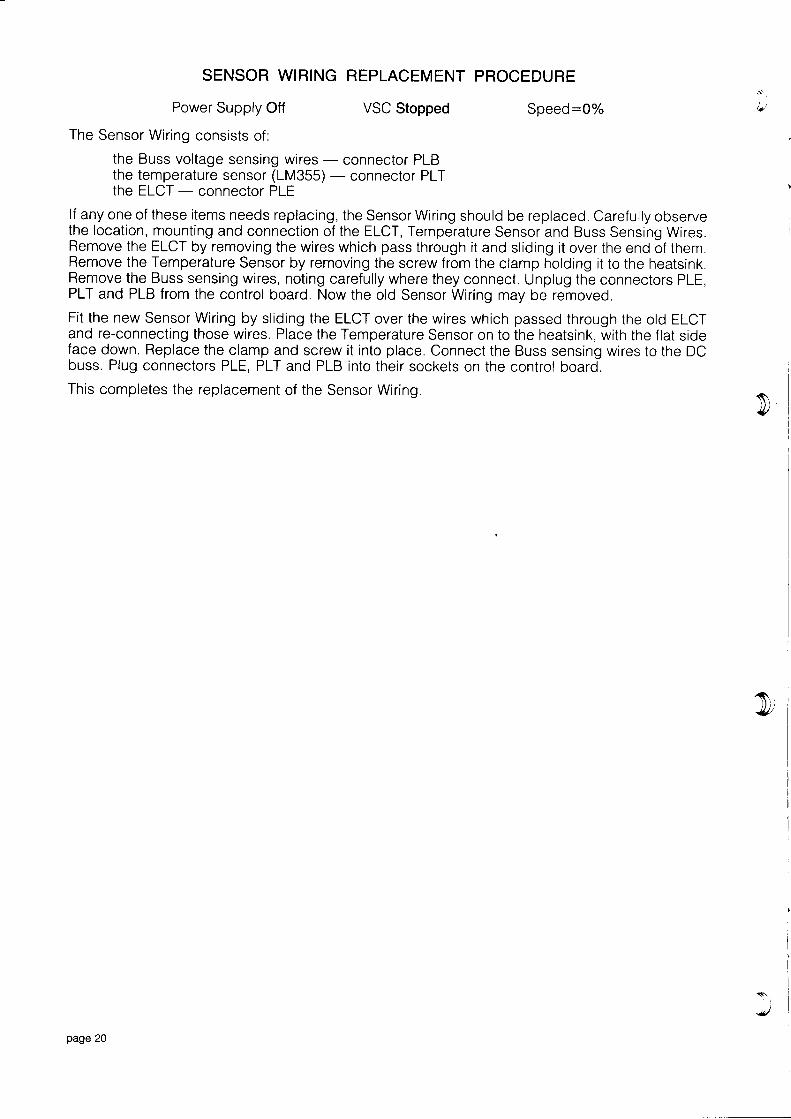
SENSOR WIRING REPLACEMENT PROCEDURE
Power Supply Off
The Sensor Wiring consists of:
VSC Stopped Speed:0%
the Buss voltage sensing wires - connector PLBthe temperature sensor (LM355) - connector PLTthe ELCT - connector PLE
lf any one of these items needs replacing, the Sensor Wiring should be replaced. Carefully observethe location, mounting and connection of the ELCT, Temperature Sensor and Buss Sensing Wires.Remove the ELCT by removing the wires which pass through it and sliding it over the end of them.Remove the Temperature Sensor by removing the screw from the clamp holding it to the heatsink.Remove the Buss sensing wires, noting carefully where they connect. Unplug the connectors PLE,PLT and PLB from the control board. Now the old Sensor Wiring may be removed.Fit the new Sensor Wiring by sliding the ELCT over the wires which passed through the old ELCTand re-connecting those wires. Place the Temperature Sensor on to the heatsink, with the flat sideface down. Replace the clamp and screw it into place. Connect the Buss sensing wires to the DCbuss. Plug connectors PLE, PLT and PLB into their sockets on the control board.This completes the replacement of the Sensor Wiring.
r\\
ly'
1\,a
'$1,4l/
s\
page 20

8&
go
c
ooN
o
Ic
ooNc
o
3g
dq
sotsN
ooo{4
o
d
o
oNc
Io
t
so
c
3IL
aeG
3It
6o
IoFd
t
oo6
oo
A
gc
Eo
G
g4
go4
gc
Bc
8I
toq
8o
4
EoI
Io
tIo
G
d
8o
G
IoG
tIG
tooc
IE EEg
t
5oc
Et4
to
G
EoCc
Eoo4
8ood
Eo
EI4
toc
goc
doc c
g8N
€c
F
oF Ng
G
F
et
F
Ic
N
o
c
o
t
F
5G
F
IN
tI=L
I5
N
o
L
n6
tNL
No
Fc
doN
ttN
t3N
t
d
8d
I
oo4
oNN
I8G
It
o
56
8G
oN4
eu aE9et
gR4
3F
c
gc
3o&
Era-
tE
oN
to
&tc
3G
IE
oaq
oFNG
RG
dooI
doo
F!
o8N
I
g4
onA
tgt
g4
o8oc
6
8F $:
A
Igt
Ft
gI
$N4
Ft
Et
tF
GEt
FL
5tIt
EI
oFt
o
d
5G
o
tFI
5N
t:
D F
FEt t
i t5 EE F
G A
3...
3EENt8c
I
tHc
B4
i*
8o
tdtsN
tic
EG
E
rF!g
e
Ic
Ic
84
IG
$t
gNI
8c
8FN
t5G
gt
!a: :, <
o
cJq o o
rio
a (
, c
I H5 =, l
II
o9
II
EEI
EoT
*ToI
F
II
EEI
8 g?d
EI
!
VSC-H lnternal Wiring Diagram
i f ri r - \ , f -
{ai
C c E
t E = s g> 6
gtI
trPEne
U)EEE&mC)
9ETozxR9trfrlA
(J
c
@
;t; ii: E;tH .iii lEi i3;=li;ii;::g:EE
opage 21
d----rr'Ei

VSC-G Internal Wiring Diagramt),
i rq
t oi r; oI t si @i ot zi <i F
$-,IaFE
rrltra
m
F]m
E
-l
Flztrl
c$ ts
AeG
oo
c
ooo
oo
A
@
N
c
o
4c
6
c
@
8c
oo o
o
I 8d c
8
N
II
I n6
c
P6
d
o 5F
8d
to
8d
o 5o
o
o
d
o cE C
r9
F
e
E
ts
Ic
N
o
4
F
F
c
€c E c
o E= F
= id :
@o
c
E
oIc
so
oF I
L eo
o
d
d
t ,@ 0o <
Z E
@o
6
Q
E
@
ec
oo
I
frz6S d
oId c
N
oc
ood
tsd
c;
Ic
oI
IeE
8 Io
c
8e
ogd
zI
!:tsc
E34
Fq
oo
E
c
Ir aN 6
c
f u
i iac
Ec
oIc
o 4L d
6 6 6
t: q
24Icoo
I q
IN
*4d
q
4
ooo
- it :
4
ooI
t
oec
ec
t ;( adt
L E
< !l J z
Io
9
roo9
o9
oo9
BI
E o9
oI
I
irt sji f;'s t;; lti ir;= IE;i !;i :5i
i r l i i
lr--ll'u6 l8JEE d=
zl
f.14
a l 4 i z
page 22

VSC-S Internal Wiring Diagram
C. 6 =F".Fo z u- U I I
lI
I
II
if
I
ir H
r O' i o: I
r EI P
i ! at zt <
; Fi-II
IJ
gE
FI
m()m
rrlv)
AFIo2a
c
@
,isi;ii= 5! ;g e ; i;eg: !;!
trr'l,-t =
E 5zz( ) <E
o
o 8oE
oo
ooI
c
dEa2
t
It
8oq
I
4
o 6E E
68t o
5c
r
o
vt
6EL
odoo
x.ytH-
N
oc
do
4
N
oE
Fddo FI
oa
8o
zs E4
Et
l q
iB? :
{o
od
oo4
oot
5*
3ego oo
t
oooA
rE: b
too
Ioc
Iot
=*; i
ct ci
, q< @5 :r l
Io9
6I
$ oI
. g lJ r l
/,_--'.-\ \- N n *
trl
trFz
()m
page 23
{J----rr'6l6L

VSC Voltage Select ion ProcedureThis procedure is only oppl icoble to
"MULTI VoLTAGE" VSC's. These VSC's hove o Port Number
"ACXXXX3",
where the "XXXX"
s tonds fo r ony combino t ion o f d ig i ts . Any VSC wi th o Por t Number tho t does no t endwith 3 con not hove i t 's input voltoge chonged. You should hove been supplied with o pocket contoining4 smol l p lug in l inks ond o sheet o f se l f odhes ive lobe ls . Fo l low the th ree s teps be low to se lec t theinput voltoge you require.
1. Translormer Tapplng SelectlonRemove the AC Power Supply from the VSC. Ensure thefi lter copocitors ore fully dischorged, Loosen the screw inthe l id of the VSC ond open the l id. Locote the controltronsformer just obove the Power Input/Motor Outputterminols. On the top of the tronsformer is o printedcircuit boord with the voltoge selection toppings. A drowingof this boord is shown opposlte, Remove the topping corefullyond reploce it on the pin odjocent to the voltoge yourequire. Close the l id ond tighten the l id screw.
2. Voltage Selectlon LlnkeLocote the Voltoge Selection Links on the VSC control boord. Refer to the drowing below for theirlocotion. From the toble below, select the input voltoge required ond plug in the l inks os shown.
3. lnput Voltage Label ChangeLocote the Input Voltoge Lobel below the Input/Output terminols on the VSC chossis. Remove theInput Vo l toge Lobe ls f rom the pocket supp l ied . Se lec t the lobe l w i th the NEW Input Vo l toge morkedon i t ond remove i t from the bocking poper. Stick i t down on top of the OLD Input Voltoge Lobel.
- 346V- 38OV- 4 1 5 V- ++ov- t-----l
AHCBOE6112
o o
Z E N E R
VSC INPUT VOLTAGESELECNON
o l o " o o ltJ- - - -tJ
PLU
F-- - - t ot o o o o l
L l - - - - i l
o P L v o
l o o o o lLl- - - -iJ
o P L v o
o
oVSC Gontrol Board
PI,J PLT PI.E PI.B PI.C PLP
a q l l o o o l l o o l l o o l l o o l l o q s a lJ L _ _ J L - J L _ - . I L _ J L _ _ - J
Voltage Selectlon Llnks
EIM| | l2lrl1lrl.l7l.l
srA
srB
50 80lg
LX5
acca. FcELrt Lur
o om v^x rccE Ea fM .,-_
F M E r e I E T " -Rrrx s ICCP ff WT
@@@@@@@@@FVID REV EN PLL PIl
rr---------1l d E o o d o o o l
offi
EF
UV
OV
OT
o o o f f i ml*ojj-b-E@=lrl2l! l4Fl.l?lt l
o a o o a oa a Z Z ao o Z a e Z oo o