contents · the lt series compressors can be applied in the high pressure ratio environment, such...
TRANSCRIPT

Contents
1. GENERAL.................................................................................................................................................. 1
2. SPECIFICATIONS .................................................................................................................................... 2
2.1 NOMENCLATURE ..................................................................................................................................... 2
2.2 LT SERIES ............................................................................................................................................... 2
2.3 SPECIFICATIONS ....................................................................................................................................... 3
2.4 APPLICATION LIMITS ............................................................................................................................... 4
3. CONSTRUCTION & FUNCTIONS .......................................................................................................... 6
3.1 DESIGN FEATURES ................................................................................................................................... 6
3.2 CAPACITY MODULATION ......................................................................................................................... 7
3.2.1 Step-type Control ............................................................................................................................... 8
3.2.2 Stepless Type Control ...................................................................................................................... 11
3.2.3 The Positions of Solenoid Valves .................................................................................................... 15
3.3 COMPRESSOR UNLOADING FOR STARTUP, AND STOP .............................................................................. 16
4. LUBRICANT ........................................................................................................................................... 17
4.1 LUBRICANT TABLE ................................................................................................................................ 17
4.2 OIL CHARGING ...................................................................................................................................... 17
4.3 OIL CHANGE ............................................................................................................................................ 18
4.3.1 Change Oil Periodically: .............................................................................................................. 18
4.3.2 Pre-cautions of Changing Oil ....................................................................................................... 18
5. SYSTEM APPLICATION ....................................................................................................................... 19
5.1 PIPING DESIGN....................................................................................................................................... 19
5.1.1 Suction and Discharge Piping Layout .......................................................................................... 19
5.1.2 Economizer Piping Layout ........................................................................................................... 21
5.1.3 Minimum Pressure Valve ............................................................................................................. 21
5.1.4 Liquid Line Filter Dryer ............................................................................................................... 22
5.1.5 Sight Glass with Moisture Indicator ............................................................................................. 22
5.2 OIL LINE ................................................................................................................................................ 23
5.2.1 Oil Supply ..................................................................................................................................... 23
5.2.2 Lubrication and Capacity Control Modulation ............................................................................. 23
5.2.3 Liquid Injection to Chamber System ............................................................................................ 24
5.2.4 Protection in Oil Line ................................................................................................................... 26
5.2.5 Oil Cooling System ...................................................................................................................... 27
5.3 LIQUID INJECTION TO MOTOR ............................................................................................................... 28
5.4 ECONOMIZER SYSTEM ................................................................................................................................... 29
5.4.1 Economizer Application .................................................................................................................. 29
5.4.2 Sub Cooler ....................................................................................................................................... 29
5.4.3 Flash Tank ....................................................................................................................................... 30
5.5 EXAMPLE OF SYSTEM LAYOUT ................................................................................................................ 31

1
6. MOTOR DESIGN .................................................................................................................................... 32
6.1 MOTOR PARAMETERS AND DESIGN ....................................................................................................... 32
6.1.1 Y-Δ Start ....................................................................................................................................... 32
6.1.2 Power source requirement ............................................................................................................ 33
6.1.3 MCC&LRA .................................................................................................................................. 34
6.1.4 Terminal cover plate. .................................................................................................................... 35
6.1.5 Terminal box................................................................................................................................. 36
7. COMPRESSOR INSTALLATION .......................................................................................................... 37
7.1 OPEN COMPRESSOR WOODEN CRATE ...................................................................................................... 37
7.2 COMPRESSOR LIFTING ........................................................................................................................... 37
7.3 COMPRESSOR INSTALLATION ................................................................................................................. 38
8. OPERATION AND MAINTENANCE.................................................................................................... 39
8.1 COMPRESSOR COMMISSIONING CHECK................................................................................................... 39
8.1.1 Check list before Start up ............................................................................................................. 39
8.1.2 Check list during operation........................................................................................................... 40
8.2 TROUBLE SHOUTING TABLE ................................................................................................................... 41
9. DIMENSIONS............................................................................................................................................ 0
10. ACCESSORIES.......................................................................................................................................... 0
10.1 ACCESSORY LIST ................................................................................................................................. 0
10.2 ACCESSORY FOR GAS REFRIGERANT LINE ............................................................................................ 1
10.2.1 Stop valve ....................................................................................................................................... 1
10.2.2 Flange bushing ................................................................................................................................ 3
10.2.3 Check valve .................................................................................................................................... 5
10.2.4 Minimum pressure valve ................................................................................................................ 7
10.3 OIL LINE ACCESSORY ........................................................................................................................... 9
10.3.1 Oil flow switch ............................................................................................................................. 9
10.3.2 External oil filter ........................................................................................................................... 10
10.3.3 Oil line solenoid valve .................................................................................................................. 11
10.3.4 Oil pressure differential switch ..................................................................................................... 11
10.4 ELECTRICAL ACCESSORY ................................................................................................................... 12
10.4.1 INT-69HBY motor protector ........................................................................................................ 12
10.4.2 Pt100 temperature controller ........................................................................................................ 14
10.4.3 300W Oil heater ............................................................................................................................ 14
10.5 OTHER ACCESSORY ............................................................................................................................ 15
10.5.1 Mounting pad ................................................................................................................................ 15
11. PERFORMANCE ....................................................................................................................................... 0
11.1 R22...................................................................................................................................................... 0
11.2 R404A ................................................................................................................................................. 6
1
1. General
A single stage screw compressor can achieve -40℃~-50℃ as the lowest SST (saturated
suction temperature). If SST -60℃~-65℃ is required, a compound two stage compressor or
multi unit of single stage compressors are necessary. Multi unit of single stage compressors
can be applied in low temperature application, but the system control is more complicated
and they occupy more space. In low temperature application such as 60℃~-65℃, a
compound two stage compressor is a better choice. In this kind of high pressure ratio
condition, the compound two stage compressor has better performance in internal leakage
(compression efficiency), high discharge temperature and reliability.
With more than 20 years of experience in design and manufacturing screw compressors,
Hanbell launched compound two stage screw compressors – LT series compressors which
have two types: LT-S series (semi-hermetic type) and LT-G series (open-type) to meet
customers’ need.
The LT series compressors can be applied in the high pressure ratio environment, such as
frozen products, tunnel freezers, cold storage, industrial cooling, process cooling, heat-pump
applications, etc.

2
2. Specifications
2.1 Nomenclature
Figure 1.
★Note: LT-G is dedicated to R717
2.2 LT Series
Figure 2.
★Note:
1) Developed model:LT-20/12, LT-30/12, LT-83/41
2) Under-developed model:LT-41/20;LT-62/20;LT-128/41;LT-235/83
0
500
1000
1500
2000
2500
LT-20/10 LT-30/12 LT-41/20 LT-62/20 LT-83/41 LT-128/41 LT-235/83
Displacement m
3/h

3
2.3 Specifications
Model
Descriptions
Low
Stage
Hi
Stage
Rated
Speed
Vi
(Low
Stage)
Vi
(High
Stage)
Capacity Control
(Step type: ST)
(Stepless type: SL) Lubrication
Type
Noise
Level Displacement 50/60Hz
50Hz 50Hz rpm
m3/h m
3/h ST SL dB
LT-20/10 201.1 99 2950
3.0
3.0
10%/50%
100% 10%
~
100%
Pressure
differential
81
LT-30/12 308 123 83
3550 LT-83/41 803.6 396
10%/50%
75%/100
%
85
Model
Weight Motor
Pressure
Test
Type Starting Voltage Insulation Protection LT-S LT-S-H LT-G
Kg Kg Kg bar
LT-20/10 598 / 560
3
phase
2 pole
Y-D 380 Class F PTC +
PT100 35 LT-30/12 620 / 570
LT-83/41 1430 1490 1280
Figure 3.

4
2.4 Application Limits
Figure 4.

5
R404A
Figure 5

6
3. Construction & Functions
3.1 Design Features
1) Unloading-type slide valve in high stage
Patented unloading-type slide valve is in high stage of LT compressors. It’s no need to
install additional external parts and unloading-type slide valve can work mechanically.
This design makes the compressor work under minimum load easily and effectively.
2) Built-in suction check valve
The built-in suction check valve saves installation space for customers’
convenience.
3) Optimal motor cooling path
Excellent design of the motor cooling path cools down the motor coil reliably
and efficiently even under serious working condition.
4) Built-in filter for economizer
The built-in filter for economizer provides further protection to compressor and
makes the system layout simpler.

7
3.2 Capacity Modulation
The capacity modulation of LT series compressors has step type (3-step / 4-step) and
stepless type. Both of these two different capacity modulations work with the slide valve,
piston rod, cylinder, and piston.
When the slide valve is at the suction side completely, the screw rotors work with full
displacement under full load. When the slide valve moves to the discharge side, the bypass
occurs between the slide valve and the suction side then the displacement and cooling
capacity decrease.
The lubricant comes from the external oil separator and passes through the oil filter then
enters into the oil inlet port of the compressor. The lubricant of the two path ways enters into
the cylinder and high-pressure lubricant flows out to the suction side by energizing the
solenoid valve to make piston move then the slide valve moves as well. Because of the
moving of the slide valve, volume of compressed refrigerant will increase or decrease to
achieve capacity modulation.
The purpose of the piston spring is to push the piston to the initial position (min. load
position). It not only alleviates the mechanical impact on compressor moving parts, but also
reduces the electrical current during compressor start up.
Figure 6

8
3.2.1 Step-type Control
1) Step-type table
Y: Energize the solenoid valve N: Do not energize the solenoid valve
LT-83/41 SV1:
(NC)
SV2:10%
(NC)
SV3:50%
(NC)
SV4:75%
(NC)
SV5:100%
(NC)
100% N N N N Y
75% Y N N Y N
50% Y N Y N N
10%
(Start/Stop) Y Y N N N
LT-20/10
&30/12
SV1:
(NC)
SV2:10%
(NC)
SV3:50%
(NC) /
SV5:100%
(NC)
100% N N N / Y
50% Y N Y / N
10%
(Start/Stop) Y Y N / N
Table 1
2) Description of Step-type control
10% load
Figure 7
When starting up the compressor, SV1(unloading) & SV2 (10%) need to be energized to
make the piston keep at the 10% position(Left side)
Under this situation, the high pressure oil passes through SV1 then goes to the right side
of the piston. At the same time, the oil in left side of the piston passes through SV2 (10%)

9
then going out to the low pressure side. In doing so, the piston can be held at the 10%
position.
★Note: 10% load is for start up only. Running the compressor at 10% load for a long time is not
recommended.
50% load
Figure 8
Under 50% load, SV1&SV3 (50%) need to be energized. Under this situation, the high
pressure oil passes to the left side of the piston continuously. At the same time, the oil passes
through SV1 then goes to the right side of the piston.
If the piston position is at the left side of the 50% hole (the loading is lower than 50%),
the oil in the right side of the piston will pass through SV3 (50%) and go out to the low
pressure side then the piston will move to right side until the position of 50% hole. It’s called
loading to the 50% position.
Vice versa, if the piston position is at the right side of the 50% hole (the loading is higher
than 50%), the oil in the left side of the piston will pass through SV3 (50%) and go out to the
low pressure side then the piston will move to left until the position of 50% hole. It’s called
unloading to the 50% position.

10
75% load
Figure 9
Under 75% load, SV1&SV4 (75%) need to be energized.
The logic of 75% load is similar to those of 50%. The piston can be held at the 75% position
by 75% hole to make the compressor run under 75% position.
100% load
Figure 10
Under 100% load, SV5 (100%) needs to be energized. Under this situation, the high
pressure oil passes to the left side of the piston continuously. At the same time, the oil in the
right side of the piston passes through SV5 (100%) then goes to the low pressure side to make
the piston be held at 100% position.

11
3) The control of the water temperature with step type
Figure 11
★Note: T & T' should be adjusted by system designer’s experience and practical application.
3.2.2 Stepless Type Control
1) Stepless-type table
Y: Energize the solenoid valve N: Do not energize the solenoid valve
SV1:
(NC)
SV2:10%
(NC)
SV5:100%
(NC)
Loading N N Y
Unloading Y Y N
Holding N N N
10% load
(Start/Stop) Y Y N
Table 2
2) Description of Stepless-type control
In stepless type control, the oil keeps going to the left side of the piston. The oil bypass
in the left side of the piston is controlled by SV2 (10%). The oil charging in the right side of
50%
Time
Start
Set point + 2T
Set point + T
Set point
Set point– T'
Stop
50% 75% 100%
t1 t2
75% 10%
1~3
min
10%
60~90 sec
Condensing water temp.

12
the piston is controlled by SV1 and oil bypass in the right side of the piston is controlled by
SV5 (100%). These three solenoid valves are controlled by temperature controller or PLC.
Loading
Figure 12
The SV5 (100%) needs to be energized and the high pressure oil goes into the left side
of the piston continuously and the oil in the right side of the piston bypasses through SV5
(100%) to the low pressure side. The piston moves to the right side and the compressor load
increases.
Unloading
Figure 13

13
The SV1 & SV2(10%) need to be energized and the high pressure oil passes through
SV1 and goes into the right side of the piston continuously. At the same time, the oil in the
left side of piston bypasses through SV2 (10%) to the low pressure side. The piston moves to
the left side and compressor load decrease.
Holding
Figure 14
Under this situation, all S/V are not energized. Although the oil from the left side of
piston goes into the cylinder continuously, the oil in the right side of the piston is not
bypassed. Therefore, the piston does not move and keeps at same position. The compressor
load is constant.
The control of the water temperature with stepless type
Figure 15
★Note:X′Top line;X〞Bottom line;X set point;H Control range;Y real value
Time
Chilled water temp.

14
Description
The real value is larger than the top line between A & B. It means the required cooling
capacity is increasing and the compressor needs to be loaded until the real value returns to
the control range.
The real value is smaller than the bottom line between C & D. It means the required
cooling capacity is decreasing and the compressor needs to be unloaded until the real
value returns to the control range.
Figure 16
Open means S/V is energized
Close means S.V is not energized
T1,T3:Pulse time 0.5~1.5seconds
T2,T4:Pause time 10~20seconds
Time
SV5(100%) Open
SV1 Close
Load
Unload Hold
t1
t2
t3
t4
SV2(10%) Close
SV1 Open
SV2(10%) Open
SV5(100%) Close

15
3.2.3 The Positions of Solenoid Valves
1. LT-83/41
Figure 17
2. LT-20/10<-30/12
Figure 18

16
3.3 Compressor unloading for startup, and stop
To lower the mechanical loading to compressor’s parts and lower the starting current
during start up. Hanbell designs for LT compressor the function of unloading startup. To
ensure compressor loads steadily, please follow Figure 37 to load step by step during the
whole loading process.
When compressor is about to shut down, it is also required to unload. Therefore ensure
the slide valve is at lowest loading position during next startup and compressor could have an
unloading startup. No matter which load it is, the compressor should unload step by step to
minimum loading before stop.
Figure 37 Compressor startup and shut down procedure
Caution:
1) Hanbell strongly suggest the control logic of startup and shut down following Figure
37
2) t>60 seconds.
3) After startup, keep the minimum load for 1~3 minutes. Before shut down, keep the
minimum load for 60~90 seconds.
4) After the compressor shut down, the SV1 & SV2(10%) need to be still energized , so as
to ensure the slide valve be in the lowest loading position, and the next startup will be
easy.
Time
Load%

17
4. Lubricant
4.1 Lubricant Table
Refrigerant R22 R404A
Saturated Condensing Temp./℃ +30 ~ +55 +30 ~ +55
Saturated Suction Temp./℃ -60 ~ -30 -65 ~ -30
Discharge Temp.Protection/℃ 110 110
Recommended Lubricant HBR-B03 HBR-B05
Specific Gravity 1.01 0.957
Specific Heat 40℃(Kcal/kg K) 0.43 0.43
Table 3
Note:
1) Please refer to the table above to select the suitable lubricant and the refrigerant and its
operation range need to be taken into consideration as well.
2) Hanbell strongly recommends do not use the lubricant which isn’t certified by Hanbell
since it may damage the compressor seriously.
3) This table is for LT series compressors only
4) The allowable lowest oil temperature is 20℃
5) After compressor stops, please turn on the oil heater. If the compressor shuts down for a
long time, the oil heater doesn’t need to be turned on. Please turn on the oil heater for
more than 2 hours before next start up.
4.2 Oil Charging
1) Make sure the system is clean and free of welding debris before charging the oil.
2) In order to ensure no moisture in the system, Hanbell suggests cleaning the system by
charging dry Nitrogen and vacuuming for several times. Try to make vacuuming time as
longer as possible to eliminate moisture in the system.
Note:
a. Hanbell strongly recommends do not use the lubricant which isn’t certified by Hanbell
since it may damage the compressor seriously.
b. Hanbell strongly recommends do not mix up different lubricant since it may damage the
compressor seriously. Please pay attention to this issue in all future maintenance.

18
4.3 Oil Change
4.3.1 Change Oil Periodically:
1)Check lubricant every 10,000 hours of continuous running. For the first operation of
the compressor, it is recommended to change the oil and clean the external oil filter
after running 2,000 hours. Check the system whether clean or not and then change oil
every 20,000 hours or after 4 years continuous running while the system operates in
good condition.
2)The oil will deteriorate if the compressor runs at high discharging temperature (Above
95℃) in the long term. Please avoid this situation, but if it’s necessary to run in this
condition, please shorten the intervals of oil changing.
4.3.2 Pre-cautions of Changing Oil
1) It is recommended to double check the quality of oil periodically in order to
maintain the lubrication performance.
2) The lubricant absorbs moisture in the air. Avoid the situation that oil expose to
air for a long time
3) It is a must to change the oil in motor burned out case, because acid material and
debris may still remain inside the system. Please follow the procedures mentioned
above to change the oil in the system. Check acidity of oil after 72 hours of
operation and then change it again until acidity of oil returns to normal value.
4) The foreign body of the oil will block up the oil line, so it is necessary to install
the oil filter in oil line. It is necessary to install the pressure sensor before and after
the oil filter. If the pressure difference between these two sensors reaches 1.5 bar,
the oil filter need to be changed.
5) The acidity of oil will affect directly the life of the motor, and it is recommended
to change the oil when PH≤6. (Please also change the filter drier at the same time
to make sure the system is in dry condition.)
6) In case of motor burned out, please not only change the compressor, but also
change the oil and check the condition of the oil periodically. If the acidity
excesses the standard, please change it immediately and always be aware of the
cleanliness and moisture content in the system.

19
5. System Application
★Note:Please consult Hanbell for parallel application and heat pump application.
5.1 Piping Design
5.1.1 Suction and Discharge Piping Layout
1) Material and structure of suction and discharge pipe
The vibration is low when the compressor is in operation so it is not
necessary to use flexible joint materials for suction and discharge tubes. However,
piping in other places must be flexible enough without causing any inner stress
for the compressor. It is recommended to use copper tube for the suction and
discharge piping in order to lower the piping vibration when the compressor is in
operation.
2) The dimensions of suction and discharge piping:
It is recommended to design the dimension of suction and discharge piping
according to Hanbell’s suggestion.(refer to 10.2.2)
3) Piping for the parallel system
To improve the system operation efficiency, it’s necessary to reduce the gas-
flow resistance and consider the oil return of suction piping.
The recommended piping of suction and discharge side for parallel system is shown
below:
Be aware of the dimension of the main pipe should not be less than the dimensions of the
other pipes to make sure the pressure drops could be controlled in reasonable ranges.

20
Recommended discharge piping
Figure 19: Discharging piping for parallel system
Recommended suction piping
Picture 20: Suction piping for parallel system
x x x
x x x
Refrigerant to oil separator
Refrigerant from
evaporator

21
4) Suction Filter
There is a built in suction filter in compressor, but it only functions as a final
protection. Please install another suction filter(25μm)for periodically cleaning.
It might be necessary to clean the suction filter for several times in initial
commissioning. If the pressure drop is higher than 0.5bar, it’s necessary to
change the filter or clean it until the system is clean. When dismantling the filter,
if the filter is damaged, please change it immediately and clean the debris left in
the piping. When installation, please confirm the direction of suction filter is
correct, and it is highly recommended to install service valves before and after
the filter chamber for easy maintenance. Hanbell recommended suction filter
layout as shown below
5.1.2 Economizer Piping Layout
1) Dimension of Economizer
A stop valve of the economizer is the standard accessory. It’s recommended
to design the dimension of the piping according to Hanbell’s suggested value.
(Refer to 10.2.2)
2) Check valve for the economizer
Parts of oil and refrigerant will flow back when the working condition is not
stable or when economizer route is closed. In order to avoid this situation, the
check valve should be installed in the economizer piping.(Refer to 10.2.3)
3) Filter for economizer
There is a built in economizer filter for protecting the compressor from
debris penetration in initial commissioning. A filter for periodical maintenance is
suggested in economizer piping.
5.1.3 Minimum Pressure Valve
The oil pressure difference between oil inlet and middle pressure
chamber/suction pressure must reach 2.5 bar in 30 seconds after start up. When the oil
Filter core

22
pressure difference is too low, the oil supply is not sufficient and may cause damage
to compressor.
So, we provide a minimum pressure valve for LT series compressor, as to
achieve high enough pressure difference quickly. The minimum pressure valve should
be mounted after the external oil filter. And the valve and the compressor middle
pressure connector should be connected by a pipe. (As shown in the Figure below)
★Note:The standard minimum pressure valve size we provide to you is the same as the discharge
valve.
★Note:Besides the standard size, other sizes are optional (refer to 10.2.4)
★Note:LT series compressor must operate with minimum pressure valve.
5.1.4 Liquid Line Filter Dryer
It will cause damage to the compressor and system even a low moisture content
left in the system. It’s a must to install filter drier on liquid line to keep the system
dry.
5.1.5 Sight Glass with Moisture Indicator
It is strongly recommended to install the sight glass with moisture indicator in
order to observe the moisture content in the system. When the moisture content is
high, it is necessary to change the filter dryer.

23
5.2 Oil Line
5.2.1 Oil Supply
The oil is supplied by the pressure difference which equals to the pressure
difference between oil separator and oil injection point. The oil is injected into the
bearings and compression casing, and then carried out of the compressor with
discharging gas. The oil will enter the oil separator again and complete the oil
circulation.
5.2.2 Lubrication and Capacity Control Modulation
The oil will be injected from two oil injection connectors which supply the oil
to suction and discharge bearings respectively as shown below. Besides, the
connector for the lubrication of suction side bearings is also used for oil supply to
capacity control system.
Figure 21 Oil supply connector of discharge bearing & suction bearing
Connector for suction
bearing lubrication and
capacity control
Connector for discharge bearing lubrication
24
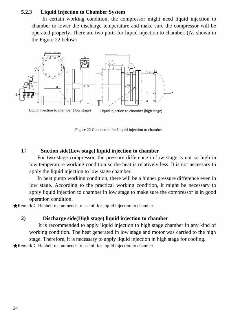
5.2.3 Liquid Injection to Chamber System
In certain working condition, the compressor might need liquid injection to
chamber to lower the discharge temperature and make sure the compressor will be
operated properly. There are two ports for liquid injection to chamber. (As shown in
the Figure 22 below)
Figure 22 Connectors for Liquid injection to chamber
1) Suction side(Low stage) liquid injection to chamber
For two-stage compressor, the pressure difference in low stage is not so high in
low temperature working condition so the heat is relatively less. It is not necessary to
apply the liquid injection to low stage chamber.
In heat pump working condition, there will be a higher pressure difference even in
low stage. According to the practical working condition, it might be necessary to
apply liquid injection to chamber in low stage to make sure the compressor is in good
operation condition.
★Remark: Hanbell recommends to use oil for liquid injection to chamber.
2) Discharge side(High stage) liquid injection to chamber
It is recommended to apply liquid injection to high stage chamber in any kind of
working condition. The heat generated in low stage and motor was carried to the high
stage. Therefore, it is necessary to apply liquid injection in high stage for cooling.
★Remark: Hanbell recommends to use oil for liquid injection to chamber.
Liquid injection to chamber (high stage) Liquid injection to chamber ( low stage)

25
Suggestions for oil line layout
Figure 23

26
5.2.4 Protection in Oil Line
The normal operation of line system is critical to the reliability of compressor。
To ensure the capacity modulation, reliability of bearing and cooling effect, please
pay attention to the point below:
1) Oil temperature
The temperature of oil needs to be strictly maintained.
When temperature of oil is too low:
The viscosity is high and it would cause insufficient oil supply and abnormal capacity
control.
It would cause high liquid refrigerant content in the oil and results in oil carry over.
The lubrication effect will be influenced as well.
When temperature of oil is too high:
The viscosity will reduce and lubrication effect is bad.
Cooling effect is bad and results in high discharge temperature. In strict condition,
the compressor may be damaged.
High temperature will deteriorate the lubrication and influence the service life of
bearing. When temperature of oil is too low:
Note
1) When compressor is running the temperature of oil should be kept between20℃~60℃
2) When compressor stops, the oil heater needs to be switched on and keep the oil
temperature above 20℃
3) When compressor is stopped for a long time, the oil heater can be switched off.
However, the refrigerant will be dissolved in oil in long term stop and the oil can’t
perform properly. Before start up, the oil heater needs to be switched on to heat up the
oil up to 20℃
★Note:Hanbell can provide the oil heater(Refer to 10.4.4)
2) Oil filter
The cleanliness of the oil is very important to screw compressor. If the welding
debris or other debris enters the compressor with oil, it would cause damage in
bearings or screw rotors. It is necessary to install an oil filter in oil line. It is suggested
to install the oil filter after the oil
It is suggested to install pressure sensor before and after the oil filter or apply
pressure difference switch to detect the pressure drop after the oil filter. If the pressure
drop reaches 1.5 bar, the compressor must be stopped for cleaning or replacing the oil
filter.
★Note:Refer to Figure 23 for layout of oil filter and pressure difference switch.
3) Oil pressure difference
The oil supply to compressor is depending on the oil pressure difference. To

27
ensure the oil supply, it is necessary to keep the pressure difference between oil inlet
and middle pressure chamber/suction pressure above 2.5 bar.
4) Oil level protection
It is suggested to install an oil level switch in oil tank or oil sump to ensure the oil
supply.
5) Oil flow protection
To ensure the oil supply and increase the reliability, an oil flow switch is also
suggested.
★Note:1)Refer to Figure 23 for oil flow switch installation
2)Hanbell provides oil flow switch(refer to 10.3.1)
5.2.5 Oil Cooling System
In high pressure ratio working condition, a lot of heat will be generated. Part of the
heat will be moved by the oil, so it is necessary to cool down the oil. Otherwise, the oil
will deteriorate and can’t function well.
An oil cooler can keep the temperature of oil in reasonable range and the
compressor can work properly even in strict working condition.
★Note:
1) It is suggested to install the oil cooler near compressor.
2.) To avoid the oil enters oil separator or compressor after compressor is stopped, it is suggested to
3.) It is necessary to control the temperature of retuned oil between 40℃~60℃
4.) A bypass way is suggested to for ease of oil temperature control. Refer to Figure 23~25
Two suggested oil cooler layout
1) Air cooled type
Figure 24 air cooled oil cooler

28
2) Water cooled type
Figure 25 water cooled oil cooler
5.3 Liquid Injection to Motor
The motor is cooled down by the gas refrigerant from low stage and economizer.
However, in strict working condition, the cooling effect of gas refrigerant is not sufficient.
The liquid refrigerant can be applied through the liquid injection port. When liquid refrigerant
enters the chamber, it is spread by gas flow and cools down the motor evenly.
Figure 26 Liquid injection to motor
★Note:
1)Refer to 2.4 for the working condition that liquid injection to motor is necessary.
2)PT 100 motor temperature sensor is a standard accessory for controlling the liquid injection solenoid
valve.
liquid injection to motor port

29
5.4 Economizer System
5.4.1 Economizer Application
Cooling capacity and efficiency will increase by applying an economizer in front of
expansion valve to get sub cool effect. Economizer has significant effect especially in high
pressure ratio working condition.
For a compound two stage compressor, the economizer is even more required. Due to its
two stage design, the economizer effect is magnified. Both cooling capacity and COP
increase are more significant in two stage than those of single stage compressor. The gas
supplied by the economizer could reduce the discharge temperature of low stage therefore the
discharge temperature at high stage can be maintained. This increases the compressor
performance, reliability and widens the application limit.
Two typical economizer systems:
5.4.2 Sub Cooler
With this form of operation, a heat exchanger (refrigerant sub-cooler) is used to sub-
cooled liquid refrigerant. The sub-cooling is achieved by injecting a part of the refrigerant
from the condenser through an expansion device in counter flow into the sub-cooler,
which then evaporates due to the absorption of heat. The superheated vapor is pulled into
the compressor at the economizer connection and mixed with the vapor, which is already
compressed in low stage.
The sub-cooled liquid is at condensing pressure with this form of operation, the pipeline
to the evaporator does not therefore require any special features, aside from insulation.
The system can be generally applied. Figure 27 shows the system with economizer, sub-
cooler.
Figure 27 Sub cooling economizer system

30
5.4.3 Flash Tank
The liquid sub-cooling is achieved with this form of operation by reducing the boiling
point pressure in an intermediate pressure vessel (flash type sub-cooler) arranged between
condenser and evaporator. This physical effect leads to the cooling of the liquid down to
the boiling point, due to evaporation of part of the liquid. To stabilize the pressure of the
vessel, a regulator is used which at the same time controls the quantity of vapor flowing to
economizer connection of the compressor.
This form of operation gives the most economical thermodynamic performance due to
direct heat exchanging. As the intermediate pressure is reduced to the boiling point
temperature this system should only be used with flooded evaporators. Figure 28 shows
the system with economizer, flash type sub-cooler.
Figure 28. Flash tank economizer system

31
5.5 Example of System Layout
Figure 29 Example of system layout

32
6. Motor Design
6.1 Motor Parameters and Design
Motor design
Standard starting method of Hanbell LT series screw compressor is Y-Δ start.
6.1.1 Y-Δ Start
Y-Δ motor connects motor coil by Y connection during starting therefore reducing
voltage on coils to 1/3 of input voltage and reconnects motor coil by △ connection after
starting. By doing so, we can decrease starting current thorough voltage drop, i.e., so-
called voltage-drop starting.
Y-Δ motor connection method is shown in the following motor wiring diagram:
In Y connection, MCM, MCS are inductive while motor leads Z,X,Y are tied together as a
neutral connecting as Y fashion. A few seconds later (3~5 sec is recommended), MCM,
MCS become deductive. Around 0.25 sec later, MCM, MCD are inductive, it turns out △
run connection.
Figure 30 Y-Δ connection
Caution:
After Y start, MCM & MCS are deductive for 0.25 sec and then MCM & MCD are
inductive for Δ run. Within as transient as 0.25 sec, pseudo short circuit might occur due to
inappropriate action of contactors, causing trip of compressors. When it occurs, we
recommend usage of adjustable Y-Δ dedicated timer or slightly lengthen span of time for
MCM, MCS deduction - MCM, MCD re-induction from 0.25 sec to 0.5 sec max directly in
micro controller or PLC program. Please refer to Y-Δ shift time diagram for details. Because

33
motor is not powered during Y-Δ shift, shorter Y-Δ shift span is suggested to prevent second
start due to decreased rotation speed. However, if Y-Δ shift span is too short,
aforementioned pseudo short circuit might occur.
Full load Amper
Starting
Current
Time
I (AMP)
Y- shift time 0.25~0.5sec
Figure 31. Y-△ transaction time diagram
Y-Δ start features
1. Starting current in Y connection is 1/3 of lock rotor ampere.
2. Starting torque in Y connection is 1/3 of lock rotor torque.
3. Acceleration of motor rotor becomes smaller at full-load starting, therefore compressors
require starting at partial load.
Except for Y-Δ start, concerning soft start or reactance start, please kindly contact
Hanbell for further information.
6.1.2 Power source requirement
Power limitation
Voltage limitation
Long term operation:within ±5% of rated voltage
Instant operation:within ±10% of rated voltage
Frequency:within ±2% of rated frequency
Caution:
Note: In the region where the electricity power is unstable, install an additional hi-low
voltage protector with ± 5% tolerance of normal voltage to ensure safe operating of the
compressor.
Unbalanced voltage
Unbalanced voltages usually occur because of variations in the load. When the load
on one or more of the phases are different from the other(s), unbalanced voltages will

34
appear. This can be due to different impedances, or type and value of loading in each
phase. Unbalanced voltages can cause serious problems, particularly to the motor.
NEMA defines voltage unbalance as follows :
Percent voltage unbalance = 100 x
NEMA states that poly-phase motors shall operate successfully under running conditions at
rated load when voltage unbalance at the motor terminals does not exceed 1%. Furthermore,
operation of a motor with over 5% unbalance is not recommended for it probably results in
motor damage.
Unbalanced voltages at motor terminals cause phase current unbalance ranging from 6 to 10
times the percent of voltage unbalance for a fully loaded motor. This causes motor over
current resulting in excessive heat that shortens motor life, and hence, eventual motor burnout.
If the voltage unbalance is great enough, the reduced torque capability might not be adequate
for the application and the motor will not attain rated speed.
Some of the more common causes of unbalance voltages are :
●Unbalanced incoming utility supply
●Open delta connected transformer banks
●Large single phase distribution transformer in the system
●Open phase on the primary 3-phase transformer in the distribution system
●Blow fuse on 3 phase bank of power factor improvement capacitors
●Unequal impedance in conductors of power supply wiring
●Unbalanced distribution of single phase loads such as lighting
●Unequal transformer tap settings
●Faults or grounds in power transformer
●Heavy reactive single phase loads such as welders
6.1.3 MCC&LRA
Model Start current LRA(A)△ △ /△ Maximum continues current
MCC(A)
LT-S-20/10 420/140 115
LT-S-30/12 620/206 170
LT-S-83/41 1430/477 404
LT-H-83/41 2625/875 620
Table 4. MCC&LRA
1) Above data based on 380V, 50Hz power supply.
2) The LRA&MCC data above has nothing to do with the refrigerant or working
condition.
(maximum voltage deviation from average voltage)
(average voltage)

35
Temperature
display module
Warning Light
Power Light
Control relay connection
Connection to discharge PTC
Connection to 3 phase main
power supply
Motor protector power
Motor embedded PTC temperature
sensor terminal
Motor embedded Pt100
temperature sensor terminal
Control output to liquid
injection solenoid valve
6.1.4 Terminal cover plate.
Figure 32 Terminal cover plate connection diagram
Table 5. Nuts specifications for bolt on terminal cover plate
Model Specs Torque (N.m)
LT-S-20/10 M12 Nut 28
LT-S-30/12 M12 Nut 28
LT-S-83/41 M12 Nut 28
LT-H-83/41 M16 Nut 30

36
6.1.5 Terminal box
An IP54 terminal box is provided as standard accessory. Please refer to below diagrams for
dimensions.
Figure 33 Terminal box dimension

37
7. Compressor installation
7.1 Open compressor wooden crate
Upon receiving the compressor, please check if the crate is intact, and compressor is in
good condition. Please also check accessories and documents to be consistent with order.
Caution:compressor is charged with 0.5~1 bar of nitrogen before delivery. Please
release the interior pressure before dismantling any parts on compressor.
7.2 Compressor Lifting
When lifting the compressor, it is recommended to use a steel chain or steel cable.
Make sure that chains, cables or other lifting equipments are properly positioned as shown
below to protect the compressor and its accessories from damaging. Keep the compressor
in horizontal position when lifting, and prevent it from crashing or falling on the ground,
hitting the wall or any other accident that may damage it or its accessories.
Caution:
1) Please ensure the steel cable weight load is sufficient.
2) Check the steel cable and hook before lifting, making sure there is no deform or crack
to avoid accident.
3) Ensure sufficient space for lifting.
Figure 34 compressor lifting

38
7.3 Compressor installation
The installation of the compressor in the refrigeration system should be accessible and
make sure that the compressor is away from the heat source to prevent heat radiation. The
compressor should also be installed as close as possible to the electrical power supply for
easier connection. It is necessary to keep good ventilation and low humidity condition in
the site. Make sure that the frame or supporter is strong enough to prevent excessive
vibration and noise while the compressor is running and must reserve enough space for
compressors’ future maintenance work.
Compressor should be installed horizontally. Meanwhile, it is recommended to install
mounting pad to avoid the compressor from delivering vibrations to the piping.
1. LT-83/41
1
Figure 35 mounting of LT-83/41
2. LT-20/10<-30/12
Figure 36 mounting of LT-20/10<-30/12

39
8. Operation and maintenance
8.1 Compressor commissioning check
8.1.1 Check list before Start up
Items Check point States or standard values
1.Compressor
and
accessories
1. Oil level of external oil
separator
2.Oil temperature
3.Open stop valves
4.Open motor liquid
injection port(angle valve)
1. High oil level window filled.
2. Before start up, heat up the oil to 40℃/
heating time is around 8Hrs.
3. Open caps of stop valves to check.
4. Open cap of angle valve cap to check.
2.Power
system
1. Voltage of main power
2. Voltage of control circuit
3. Insulation resistance
value of the motor
between phase to phase
and phase to ground.
4. Power terminals and
connection.
5. Grounded
6. Settings of switches,
sensors and controllers.
1. Main power voltage fluctuation range
within ±5%. Instant voltage drop during
start up is less than 10%;
2. Voltage of auxiliary power is 220V±10%.
3. Resistance value should exceed 50MΩ.
4. Power terminals are firmly fixed on
terminal block and well insulated. Keep
wire cables away from heat source and
sharpened metal. Power terminals are fixed
firmly and well insulated. Terminal screw
and block are both required.
5. Installation confirmation.
6. Check original value of design.
3.Piping
system
1. Check the piping is
firmed.
2. Check if there is any
leakage.
1. Observation or manual check.
2. Apply leakage test liquid to check
especially on connections and welding
junctions.
4.Protection
devices
1. Winding temperature
2. Discharge temperature
3. Oil level switch
4. PT100 motor
temperature sensor
1. Not active(close circuit)
2. Not active(close circuit)
3. Oil is full(close circuit)
4. Same or close to environment
temperature.
Table 6 Start up check list

40
8.1.2 Check list during operation
1)Start up compressor for 0.5~1 second. Confirm the rotation direction through
monitoring suction and discharge pressure.(correct rotation direction: suction pressure
goes down and discharge pressure goes up at the same time)
2)Check if the oil sight glass on external oil line is full of lubricant after start up. In case
of abnormal, please check pressure difference (oil pressure differential supply), oil
filter and oil line solenoid valve.
3)There will be some oil foams in the oil separator during start up but only in a short
time. When working under rated working condition, the foam will disappear.
Otherwise it means the system is without sufficient oil or there is oil carryover
problem.
4)Compressor’s operating working condition adjustment as follows: discharge
temperature is 30K above condensing temperature and suction superheat within 15K.
5)The whole system should pass vibration test, especially the piping. If there is
abnormal vibration and noise from compressor, please contact HANBELL.
6)Below items need to be checked every day, when compressor is operating in a long
time: Compressor running data such as 3 phase voltage, current, etc. Oil temperature,
oil level, all the sensors, wiring junctions, and oil line window.
7)When condensing unit operates in job site, we should beware of its complementary
devices and the maintenance schedule after first commissioning.
8)To keep the lubricant viscosity normal at low ambient temperature and to ensure the
function of bearing lubrication, it is suggested to keep the oil heater in the external oil
separator “on” after compressor is turned off. This is to prepare for the next start up.

41
8.2 Trouble shouting table
Issue Possible Reason
Motor temperature
sensor trip
1. Motor over load, liquid injection solenoid valve malfunctions.
2. Motor temperature sensor switch malfunction.
3. Power system malfunction
4. Defective motor coil.
5. Liquid injection expansion valve malfunctions.
Defective Motor
Insulation
1. Power bolts condenses.
2. Defective Motor.
3. Defective power bolts.
4. Defective magnet contactor.
5. Acid in the system deteriorates the insulation
6. Long term running at high temperature cause motor insulation
deterioration.
7. Frequent start up.
8. Too much water content in the refrigerant.
Unable to start up
the motor or
switch
1. Compressor start up at full load
2. Voltage is too low or wrong.
3. Too much voltage drop, and the magnet contactor s can’t induct.
4. Motor malfunction
5. Phase loss or phase reverse
6. Motor protection switch is active.
7. Wrong connection of motor terminals.
8. Timer of Y△ starting malfunctions.
9. Capacity of over load relay is too small.
10. Magnet contactors malfunction.
Abnormal
vibration or noise
1. Bearings are damaged.
2. Liquid compression.
3. Overheated rotors touch each other or touched the chamber
4. Oil loss causes bad lubrication effect.
5. Inner parts are loose.
6. Defective piping causes resonance.
7. Objects enter the compression chamber
Discharge
temperature is too
high
1. Suction superheat is too high. (less refrigerant volume or
expansion valve malfunctions)
2. High pressure side is abnormal. (bad cooling effect, air
penetrates in the system, temp. of cooling water is too high,
cooling water flow is too less, heat exchange capability of
condenser is bad.)
3. Compression ratio is high without liquid injection.

42
4. Bearings are damaged. Rotors friction.
5. Oil loss or oil level is too low.
6. Suction check valve malfunctions.
Time of reverse
rotation is too long
1. Stop action is not set in control logic.
2. Piston of suction check valve is blocked, and can’t close.
System low
pressure alarm
1. Lack of refrigerant
2. Evaporator frosts seriously, and affects the heat exchange.
3. Opening of expansion valve is too small.
4. Suction filter is blocked by ice or debris.
5. Capacity of evaporator is too small.
6. Wrong setting of the low pressure protection.
System high
pressure alarm
1. Too much refrigerant.
2. Condenser is blocked by debris, dust or penetrated by air.
3. Discharge temperature is too high.
4. Expansion valve is blocked by ice or debris.
5. The capacity of condenser is too small.
6. Wrong setting of high pressure protection.
Oil flow alarm
1. Oil flow switch malfunctions.
2. The condensing pressure is not built up.
3. Oil line blocked.
4. Oil line solenoid valve malfunctions.
Discharge
temperature is too
low
1. Liquid compression.
2. Temperature of returned oil is too low.
3. Opening of liquid line expansion valve is too large.
4. Opening of economizer expansion valve is too large.
Oil carry over
1. Discharge temperature is too low.
2. Demister of oil separator malfunctions.
3. Oil temperature is too low(oil heater is not switched on)
4. Liquid compression.
5. Opening of economizer expansion valve is too large.

9. Dimensions
9.1 LT-S-20/10
No.No. SPECIFICATIONNAME
75% SV4
10% SV1
100% SV2
8
1
7
6
5
4
3
2
2"
3"
1 1/2"
9
11
10
50% SV3
1/4"Flare
12
1/4"Flare
16
15
14
13 1/4"Flare
17
1/4"Flare
1/2"
3
24
5
3/8"Flare
18 1/4"Flare
Oil hydraulic cylinder
Solenoid valve
Solenoid valve
Cable box
Solenoid valve
ECO shut-off valve
Suction shut-off valve
Discharge shut-off valve
Solenoid valve
Liquid injectionconnector
Oil inlet connector
Oil inlet connector
Three-warAngle valve
Angle valve
Safety Valve
Suction filter
Check Valve
Liquid(oil or refrigerant)
injection connector
3
Item1
2
Date
5
4
7
6
Modification Changer
3
1
2
5
4
7
6
Approver
LT-S-2010Model
Name Compressor outline
上 海 漢 鐘 精 機 股 份 有 限 公 司
SPECIFICATIONNAME

1
9.2 LT-S-30/12
3
2
4
5
No.No.
75% SV4
10% SV1
100% SV2
8
1
7
6
5
4
3
2
2"
3"
1 1/2"
9
11
10
50% SV3
1/4"Flare
12
1/4"Flare
16
15
14
13 1/4"Flare
17
1/4"Flare
1/2"
3/8"Flare
18 1/4"Flare
Oil hydraulic cylinder
Solenoid valve
Solenoid valve
Cable box
Solenoid valve
ECO shut-off valve
Suction shut-off valve
Discharge shut-off valve
Solenoid valve
Liquid injectionconnector
Oil inlet connector
Oil inlet connector
Three-warAngle valve
Angle valve
Safety Valve
Suction filter
Check Valve
Liquid(oil or refrigerant)
injection connector
3
Item1
2
Date
5
4
7
6
Modification Changer
3
1
2
5
4
7
6
Approver
LT-S-3012Model
Name Compressor outline
上 海 漢 鐘 精 機 股 份 有 限 公 司
SPECIFICATIONNAME SPECIFICATIONNAME

2
9.3 LT-S-83/41
No.No.
75% SV4
10% SV1
100% SV2
8
1
7
6
5
4
3
2
2-1/2"
5"
2"
9
11
10
50% SV3
3/8"Flare
5/8"Flare
13 3/8"Flare
17
16
15
14 3/8"Flare
19
18
20
1/4"Flare
1/4"Flare
2"
1"
21 2 1/2"
2
12
1/4"Flare
5/8"Flare,motor cooling
2
connector
Oil hydraulic cylinder
Solenoid valve
Solenoid valve
Cable box
Solenoid valve
ECO shut-off valve
Suction shut-off valve
Discharge shut-off valve
Solenoid valve
Liquid injection
Oil inlet connector
Oil inlet connector
Oil inlet connector
Liquid (oil or refrigerant)
Three-way Angle valve
Angle valve
Nut
connectorLiquid injection
ECO check valve
injection connector
3
Item1
2
Date
5
4
7
6
Modification Changer
3
1
2
5
4
7
6
Approver
LT-S-8341Model
Name Compressor outline
Discharge check valve
上 海 漢 鐘 精 機 股 份 有 限 公 司
Refrigerant service valve
1/4"
SPECIFICATIONNAME SPECIFICATIONNAME

3
9.4 LT-G-20/10
3
24
5
No.No.
Oil hydraulic cylinder
Solenoid valve
Solenoid valve
75% SV4
10% SV1
Cable box
Solenoid valve 100% SV2
8
1
7
6
5
4
3
2
2"
ECO shut-off valve
Suction shut-off valve 3"
Discharge shut-off valve
1 1/2"
Solenoid valve9
11
10
50% SV3
1/4"Flare
12
1/4"Flare
16
15
14
13 Angle valve 1/4"Flare
17
Angle valve
Safety Valve
1/4"Flare
1/2" (optional)
3/8"FlareLiquid injection
Suction filter
Check Valve
18Liquid(oil or refrigerant) 1/4"Flareinjection connector
connector Motor-assistant cooling
Oil inlet connector
Oil inlet connector
3
Item1
2
Date
5
4
7
6
Modification Changer
3
1
2
5
4
7
6
Approver
LT-G-2010Model
Name Compressor outline
SPECIFICATIONNAME SPECIFICATIONNAME
上 海 漢 鐘 精 機 股 份 有 限 公 司

4
9.5 LT-G-30/12
3
2
4
5
No.No.
Oil hydraulic cylinder
Solenoid valve
Solenoid valve
75% SV4
10% SV1
Cable box
Solenoid valve 100% SV2
8
1
7
6
5
4
3
2
2"
ECO shut-off valve
Suction shut-off valve 3"
Discharge shut-off valve
1 1/2"
Solenoid valve9
11
10
50% SV3
1/4"Flare
12
1/4"Flare
16
15
14
13 Angle valve 1/4"Flare
17
Angle valve
Safety Valve
1/4"Flare
1/2" (optional)
3/8"FlareLiquid injection
Suction filter
Check Valve
18Liquid(oil or refrigerant) 1/4"Flareinjection connector
connector Motor-assistant cooling
Oil inlet connector
Oil inlet connector
3
Item1
2
Date
5
4
7
6
Modification Changer
3
1
2
5
4
7
6
Approver
Model
Name
LT-G-3012
Compressor outline
SPECIFICATIONNAME SPECIFICATIONNAME
上 海 漢 鐘 精 機 股 份 有 限 公 司

5
9.6 LT-G-83/41
No.No.
Oil hydraulic cylinder
8
1
7
6
5
4
3
2
2-1/2"
5"
2"
9
11
10
Oil inlet connector 5/8"Flare
12
3/8"Flare
16
15
14
13
3/8"Flare
1/4"Flare
17
1/4"Flare
1/4"Flare
1/4"Flare
75% SV4
10% SV1
100% SV2
50% SV3
3/8"Flare
1"
Suction shut-off valve flage
ECO shut-off valve flage
Discharge shut-off valve flage
Solenoid valve
Solenoid valve
Solenoid valve
Solenoid valve
Oil inlet connector
Liquid(oil or refrigerant)
injection connector
Liquid(oil or refrigerant)
injection connector
Angle valve
Nut
Angle valve
Connect
Connect
3
Item1
2
Date
5
4
7
6
Modification Changer
3
1
2
5
4
7
6
Approver
上 海 漢 鐘 精 機 股 份 有 限 公 司
Model
Name
LT-G-8341
Compressor outline
SPECIFICATIONNAME SPECIFICATIONNAME

6
9.7 LT-S-83/41-H
No.No.
75% SV4
10% SV1
100% SV2
8
1
7
6
5
4
3
2
2-1/2"
5"
2",经济器接口
9
11
10
50% SV3
3/8"Flare
5/8"Flare
12 3/8"Flare
16
15
14
13
5/8"Flare
3/8"Flare
1/4"Flare
19
18
17
20
1/4"Flare
1/4"Flare
1/4"Flare
2"
1"
connector
Oil hydraulic cylinder
Solenoid valve
Solenoid valve
Cable box
Solenoid valve
ECO shut-off valve
Suction shut-off valve
Discharge shut-off valve
Solenoid valve
Liquid injection
Oil inlet connector
Oil inlet connector
Oil inlet connector
connectorLiquid injection
Angle valve
Angle valve
Nut
connectorLiquid injection
Refrigerant service valve
ECO check valve
3
Item1
2
Date
5
4
7
6
Modification Changer
3
1
2
5
4
7
6
Approver
上 海 漢 鐘 精 機 股 份 有 限 公 司
LT-S-8341-HModel
Name Compressor outline
SPECIFICATIONNAME SPECIFICATIONNAME


10. Accessories
Hanbell provides or designs standard or optional accessories for various kind of
applications.
10.1 Accessory list
Accessory list ● Standard
△ Optional
Item Description Q’ty Standard/optional
1. Motor protector-INT69HBY 1 ●
2. Suction stop valve 1 ●
3. Discharge stop valve 1 ●
4. Economizer stop valve 1 ●
5. Suction flange bushing 1 ●
6. Discharge flange bushing 1 ●
7. Economizer flange bushing 1 ●
8. Suction check valve 1 △
9. Discharge check valve 1 △
10. Economizer check valve 1 △
14. Suction filter(suction side) 1 ●
14. Suction filter(middle pressure
side) 1 ●
11. Pressure difference switch(manual
reset) 1 ●
12. Mounting pad 8 ●
13. Economizer muffler 1 △
15. Minimum pressure valve 1 △
16. HBR-B03 Oil △
17. Flow switch 1 △

1
10.2 Accessory for gas refrigerant line
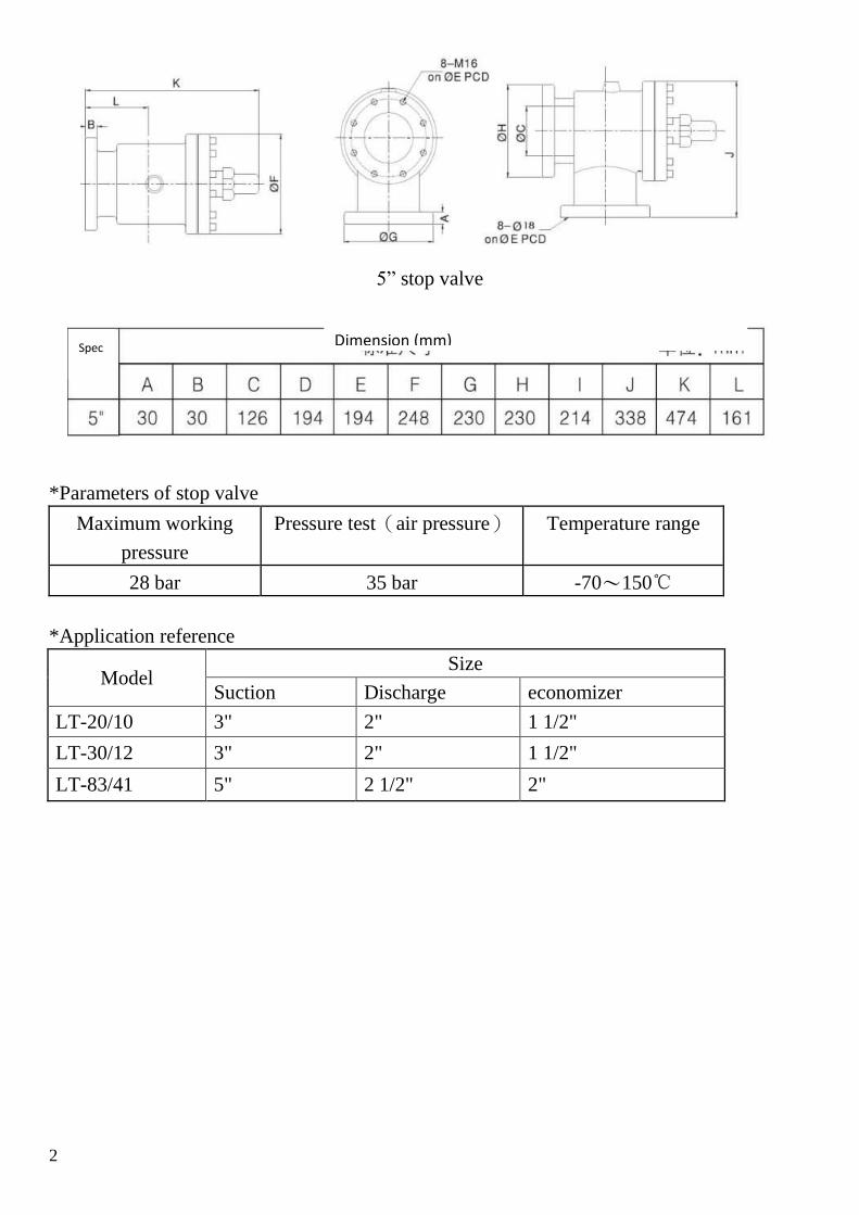
10.2.1 Stop valve
For ease of maintenance, it is suggested to install suction, discharge, and economizer
stop valve. Dimension and spec are shown below:
Dimension (mm) Spec
2
5” stop valve
*Parameters of stop valve
Maximum working
pressure
Pressure test(air pressure) Temperature range
28 bar 35 bar -70~150℃
*Application reference
Model Size
Suction Discharge economizer
LT-20/10 3" 2" 1 1/2"
LT-30/12 3" 2" 1 1/2"
LT-83/41 5" 2 1/2" 2"
Dimension (mm) Spec

3
10.2.2 Flange bushing
Standard flange bushing
Model Discharge Suction Economizer
Steel Copper Steel Copper Steel Copper
LT-
20/10 2” 2 1/8” 3” 3 1/8” 1 1/2” 1 5/8”
LT-
30/12 2” 2 1/8” 3” 3 1/8” 1 1/2” 1 5/8”
LT-
83/41 2 1/2” 2 5/8” 5” 5 1/8” 2“ 2 1/8”
Note :If the specs of flange bushings are not specified in order, Hanbell will provide standard parts.
Please refer to the table below for other specs.
Model Position Material of piping Dimension
A B C D E
LT-
20/10
LT-
30/12
Discharge
Copper
1 5/8"
50 90 30
41.6 55
1 3/4" 44.8 55
2" 51.1 62
2 1/8" 54.3 65
2 1/2" 63.8 74
2 5/8" 67 74
Steel 1 1/2" 49.3 60
2" 61.3 74
Suction Copper
2'
66 120 45
51.1 62
2 1/8" 54.3 65
2 3/8" 60.7 71
2 1/2" 63.8 74

4
2 5/8" 67 77
3" 76.6 87
3 1/8" 79.8 90
Steel
2" 61.3 76
2 1/2" 77.2 92
3" 90.2 103
Economizer
Copper
1 1/2"
52 75 35
38.3 49
1 5/8" 41.6 52
1 3/4" 44.8 55
2" 51.1 62
2 1/8" 54.3 65
Steel 1 1/4" 43.3 58
1 1/2" 49.3 64
LT-
83/41
Discharge
Copper
1 5/8"
60 110 35
41.6 52
1 3/4" 44.8 55
2" 51.1 62
2 1/8" 54.3 65
2 1/2" 63.8 74
2 5/8" 67 77
3 1/8" 79.8 90
Steel
1 1/2" 49.3 64
2" 61.3 76
2 1/2" 77.2 90
Suction
Copper
4 1/8" 80
174 35
105.1 121.2
5 1/8" 75 130.5 146.5
5" 75 127.5 146.5
Steel 4" 80 115.6 134
5" 75 141.3 154
Economizer
Copper
1 5/8"
50 90 30
41.6 55
1 3/4" 44.8 55
2" 51.1 62
2 1/8" 54.3 65
2 1/2" 63.8 74
2 5/8" 67 74
steel 1 1/2" 49.3 60
2" 61.3 74

5
10.2.3 Check valve
Horizontal type check valve is provided in discharge side and economizer. When
compressor is stopped, the teflon valve plate will be pushed by spring force to close the
opening. This reduces the time of reverse rotation to protect the compressor.
1)Economizer check valve(Horizontal type)
Spec Dimension: mm
A B C D E F G H I
2” 102 6 53 69 91 65 90 85 5
2 1/2 122 6 69 89 111 85 110 97 5
3 138 6 80 99 121 95 120 108 5
4 163 6 96 124 146 120 145 123 5
Item 1 2 3 4 5 6 7 8
Description body clip spring valve
plate plate nut
Lead
plate rod

6
2)Discharge check valve(Horizontal type)
Spec Dimension: mm
A B C D E F G H I J
1 1/2 86 4 55 59 76 42 60 75 80.5 6
2” 102 4 65 69 91 53 70 90 85 6
2 1/2 122 4 85 89 111 67 90 110 97 6
3 138 4 95 99 121 80 100 120 108 6
4 163 4 120 124 146 96 125 145 123 6
6” 238 5 190 195 216 146 190 215 160 6
Note: the size of check valve correspond to those of stop valve. Refer to 10.2.1
Item 1 2 3 4 5 6 7 8
Description body clip spring valve
plate gasket nut
Lead
plate rod

7
10.2.4 Minimum pressure valve
Minimum pressure valve is useful in cold start condition. During the cold start
period, because the system’s condensing temperature is still low, the discharge pressure
will stay at a quite low level which means the pressure differential between discharge and
suction side will not be enough for compressor to act normally. Under such working
condition, compressor might have difficulties to load itself. Oil supply to bearings and
internal cooling might be not enough which will cause severe damage to those moving
parts in the end. With minimum pressure valve, the pressure differential can be built
shortly after the start up, so the capacity control and oil supply to those moving parts
won’t be a problem. Therefore, the compressor protection can be achieved. In addition to
protection function, it can also act as check valve to reduce the reverse running time after
compressor’s stopping.
Spec Pressure difference
to open
Maximum working
pressure
Temperature
range Pressure drop
1.5"
3.6±0.3Bar 28Bar <120℃ <0.1Bar
2"
2.5"
3"
4"
5"
6"
To condenser
From oil separator outlet
Connect to compressor
middle pressure side
Pressure before valve
Pressure after valve

8
规格尺寸
1-1/2" 2"
2-1/2" 3"
4"
A B C D E F G H I J K
底部视图
L
235 213 109 55 44 44 109 M16*2 105 109 18 105247 231 122 68 55 55 122 M16*2 120 122 18 120
300 242 134 84 70 70 134 M16*2 140 134 18 140
364 264 153 98 84 84 153 M20*2.5 160 153 22 160
413 345 230 113 100 100 171 185 171 22 185M20*2.5
底部视图
规格尺寸
5"
6"
A B C D E F G H I J
503 399 270 142 125 125 270 225 225 270
531 435 305 170 150 150 305 260 260 305
Spec Dimension: mm
Dimension: mm Spec

9
10.3 Oil line accessory
10.3.1 Oil flow switch
An oil flow switch should be installed in the oil returned line from external oil
separator to protect compressor.
Spec:
Type Dimension Connector
3/8” flow switch DN10 3/8〃
5/8” flow switch DN16 5/8〃
1” flow switch DN25 1〃
Outline of oil flow switch
Parameters:
Maximum working pressure: 25bar Maximum voltage: 250VAC
Maximum working temperature:100℃ Minimum protection flow:0.7L/min
Protection class: IP65 Maximum pressure drop at maximum
flow: 0.01bar
Maximum current: 5A

10
10.3.2 External oil filter
The oil filter is 300 mesh and can be reused by cleaning.
Outline of external oil filter
Spec A
(mm)
B
(mm)
C
(mm)
D
(mm) 3/8”
(Φ10)
89 340 200 55
5/8”
(Φ16)
89 345 200 69
1”
(Φ25.5)
140 370 218 110
Spec of external oil filter
Structure
1.bolts 2.cover plate 3.gasket 4.spring 5.filter core
6.O-ring 7.oil inlet 8.body 9.oil outlet 10.angel valve

11
Maximum working pressure: 35bar
Maximum working temperature:105℃
Power source:220V/ 50Hz
10.3.3 Oil line solenoid valve
Arrow on the bottom shows the correct direction
10.3.4 Oil pressure differential switch
Function:Detect the pressure drop before and after the oil filter. If the pressure difference
reaches trip point the switch will be active to prevent the debris from blocking the filter and
cause oil supply problem.
Spec:Standard trip value is 1.5 bar and manual reset.
Description:Connect the pressure sensor before and after the external oil filter. When it
is active, clean or change the oil filter.
(低压端)
(高压端)
item:diff.pressure controls
Model:HB-DPS-1.5
1 2
3 4
In normal case 1-2 is connected.
When pressure difference reaches set
point, 3-4 are connected.
When pressure difference is under
set point, push the manual reset
button and 1-2 will be connected.

12
10.4 Electrical accessory
10.4.1 INT-69HBY motor protector
In order to protect compressor, each RC2 series compressor has been installed three
PTC temperature sensors inside motor coil and another one at the discharge side of
compressor. These sensors are connected to an INT69HBY control module to monitor the
motor and discharge temperature. If the temperature in one of the positions monitored
exceeds the nominal response temperature of the respective PTC thermistor, the sensor
resistance increases and the INT69HBY control module output relay trips. The module
resets when the temperature drops below the response temperature by approx. 5K. The
output replay provides a potential-free change-over contact and is energized as long as the
nominal response temperature is not exceeded.
V/2
W/3
U/1
X/8
Y/9
Z/7
A B
B Set:Pt100Ω/Pt1000Ω(Optional)
A Set:PTC
V/2
W/3
U/1
X/8
Y/9
Z/7
A B
B Set:Pt100Ω/Pt1000Ω(Optional)
A Set:PTC

13
Other major functional descriptions are as follow:
1. After the supply voltage has been connected, a three second initialization period follows.
Provide the PTC chain resistance is below the reset threshold (2.75kΩ), the relay trips after
these 3 seconds have expired.
2. 1 to 9 PTC thermistors with different nominal response temperature may be connected
serially to the PTC input.
3. If any thermistor resistance increases above trip level the relay drops out. This failure
results in a lockout. (5 minutes delay for 1st PTC failure, 60 minutes delay for 2nd failure,
lockout for 3rd failure.)
4. If a rapid temperature increase is detected (locked rotor condition), the output relay drops
out. This failure results in a lockout.
5. The phase monitoring of the three phase motor voltage becomes active 1 second after
motor has started, for duration of 10 seconds. In case of a wrong phase sequence or a phase
failure, the relay switches of and locks.
6. The Lock-out and delay time may be lifted by cycling the power off for approx. 5 seconds.
7. To avoid nuisance tripping due to reverse running after shutdown (pressure equalization),
the phase monitoring function is only re-enabled approx. 20 seconds after motor stop.
8. A dual LED (red / green) provides additional information about the motor protector and
compressor status.
9. The relay is fed out as a N/O dry contact, which is closed under good conditions.
10. Sensor and supply circuits are galvanic isolated.
11. The motor protector is not suitable for application of frequency converters.
Technical data:
●Supply voltage ●Relay output
AC 50/60 Hz 115/120V-15 …+10% 3VA max. AC 240V, max. 2.5A, C300
AC 50/60 Hz 230/240V-15…+10% 3VA min. > 24V AC/DC, >20 mA
●Ambient temperature ●Phase monitor
-30 … +70 ℃ 3 AC, 50/60Hz, 200 ~ 575 V ± 10%
Blink code display& diagram:
A Set: Motor PTC Terminal
Motor protector connection diagram
indicates PTC sensor exceeds
its response temperature
Power
Power
Motor
Supply
Button
Press
(NC)
Temp. PTC
Temp. PTC
Discharge
Oil
Relay
Output
Error Blink Codes
PTC Temperature Error
1st: 5min time delay after PTC < R reset
3rd: Lockout after three consecutive PTC
2nd: 60min time delay after PTC < R reset
Timer delay active (PTC < R reset)
Short
interruption
Phase failure
Internal error
temp errors within 24hrs
Phase sequence
Long
interruption
Auto reset for INT69HBY
,but not for M-PI-S28

14
10.4.2 Pt100 temperature controller
接线图尺寸外观图
10.4.3 300W Oil heater
Before start up after a long term stop, please switch on the oil for 8 hours to make sure
the temperature inside compressor is higher than ambient temperature to ensure the
lubrication effect.
Spec:300W;220V;IP54;UL certificate.
Parameters:
Power source:220 VAC±10% 50/60Hz
tolerance:±0.5℃
Environment temperature:-10~+60℃
RH:20%~90%(not condense)
Current:1.5VA
Capacity of relay:8A 250VAC/30VDC
Protection class:Front cover IP54
Rear IP20
Weight:0.34kg

15
10.5 Other accessory
10.5.1 Mounting pad
To reduce the vibration level, mounting pads are suggested for installation. The torque
value to tighten the mounting pad:20~30N·m。
Spec:
压缩机减振垫
Item A(mm) B(mm) C(mm) D(mm) E(mm) Model
1 50 55 20 20 20 LT-20/10<-30/12
2 80 100 20 25 25 LT-83/41

11. Performance
11.1 R22
LT-S-83/41 for R22 WITH ECO(380V 50HZ)
CT ℃ ET ℃ -60 -55 -50 -45 -40 -35 -30
30.0
Q(kW) 74.80 98.50 133.13 171.90 229.20 300.10 328.20
P(kW) 92.20 98.10 100.10 106.10 113.50 120.10 127.20
I(A) 164.30 172.80 178.60 184.90 195.20 203.70 214.60
COP 0.81 1.00 1.33 1.62 2.02 2.50 2.58
35.0
Q(kW) 70.00 95.06 123.01 160.00 207.63 267.20 289.99
P(kW) 100.00 102.07 107.33 114.50 120.72 129.06 138.64
I(A) 130.07 172.32 181.19 193.30 203.79 217.88 234.05
COP 0.70 0.93 1.15 1.40 1.72 2.07 2.09
40.0
Q(kW) 63.90 94.35 122.09 154.94 193.19 237.35 260.40
P(kW) 106.50 111.03 116.39 122.78 130.09 138.54 148.22
I(A) 179.80 187.45 196.49 207.27 219.62 233.88 250.22
COP 0.60 0.85 1.05 1.26 1.49 1.71 1.76
45.0
Q(kW) 62.80 85.90 121.07 153.61 191.56 235.31 254.50
P(kW) 116.29 120.92 126.38 132.87 140.39 148.94 158.72
I(A) 196.32 204.14 213.36 224.31 237.01 251.44 267.96
COP 0.54 0.71 0.96 1.16 1.36 1.58 1.60
50.0
Q(kW) 66.40 82.90 113.10 154.20 181.60 221.30 258.20
P(kW) 137.40 138.10 143.40 150.10 158.00 167.40 175.30
I(A) 230.80 235.40 244.50 254.40 240.10 254.30 266.30
COP 0.50 0.60 0.79 1.03 1.15 1.32 1.47

1
LT-S-83/41 for R22 WITH ECO(380V 60HZ)
CT ℃ ET ℃ -60 -55 -50 -45 -40 -35 -30
30.0
Q(kW) 90.51 119.19 161.09 208.00 277.33 363.12 397.12
P(kW) 109.72 116.74 119.12 126.26 135.07 142.92 151.37
I(A) 195.52 205.63 212.53 220.03 232.29 242.40 255.37
COP 0.82 1.02 1.35 1.65 2.05 2.54 2.62
35.0
Q(kW) 84.70 115.03 148.84 193.60 251.23 323.31 350.88
P(kW) 119.00 121.47 127.72 136.26 143.65 153.58 164.98
I(A) 154.78 205.06 215.61 230.03 242.51 259.28 278.52
COP 0.71 0.95 1.17 1.42 1.75 2.11 2.13
40.0
Q(kW) 77.32 114.16 147.73 187.47 233.76 287.20 315.08
P(kW) 126.74 132.13 138.50 146.10 154.81 164.86 176.38
I(A) 213.96 223.06 233.82 246.65 261.34 278.31 297.76
COP 0.61 0.86 1.07 1.28 1.51 1.74 1.79
45.0
Q(kW) 75.99 103.94 146.50 185.87 231.78 284.73 307.95
P(kW) 138.38 143.90 150.39 158.12 167.06 177.24 188.88
I(A) 233.62 242.93 253.90 266.93 282.04 299.21 318.87
COP 0.55 0.72 0.97 1.18 1.39 1.61 1.63
50.0
Q(kW) 80.34 100.31 136.85 186.58 219.74 267.77 312.42
P(kW) 163.51 164.34 170.65 178.62 188.02 199.21 208.61
I(A) 274.65 280.13 290.96 302.74 285.72 302.62 316.90
COP 0.49 0.61 0.80 1.04 1.17 1.34 1.50

2
LT-S-30/12 for R22 WITH ECO(380V 50HZ)
CT ℃ ET ℃ -60 -55 -50 -45 -40 -35 -30
30.0
Q(kW) 32.13 39.93 49.94 63.56 78.46 99.16 116.99
P(kW) 31.88 34.83 34.94 36.46 38.48 39.51 45.56
I(A) 53.82 58.80 58.99 61.55 64.95 66.71 76.91
COP 1.01 1.15 1.43 1.74 2.04 2.51 2.57
35.0
Q(kW) 30.14 38.33 48.30 61.74 75.08 93.45 110.25
P(kW) 34.70 36.80 37.70 40.08 43.10 45.10 52.00
I(A) 58.58 62.13 63.65 67.66 72.76 76.14 87.79
COP 0.87 1.04 1.28 1.54 1.74 2.07 2.12
40.0
Q(kW) 28.26 36.78 46.71 59.98 71.83 88.07 103.90
P(kW) 37.77 38.88 40.68 44.06 48.28 51.48 59.35
I(A) 63.76 65.64 68.67 74.39 81.51 86.90 100.20
COP 0.75 0.95 1.15 1.36 1.49 1.71 1.75
45.0
Q(kW) 27.41 34.02 43.82 56.73 68.44 83.11 98.05
P(kW) 41.09 42.99 43.79 46.30 50.81 54.25 62.55
I(A) 69.36 72.58 73.92 78.17 85.77 91.58 105.59
COP 0.67 0.79 1.00 1.23 1.35 1.53 1.57
50.0
Q(kW) 26.59 31.46 41.10 53.65 63.78 74.20 92.53
P(kW) 44.70 47.54 47.14 48.66 53.47 57.17 65.91
I(A) 75.46 80.25 79.58 82.14 90.26 96.51 111.27
COP 0.59 0.66 0.87 1.10 1.19 1.30 1.40

3
LT-S-30/12 for R22 WITH ECO(380V 60HZ)
CT ℃ ET ℃ -60 -55 -50 -45 -40 -35 -30
30.0
Q(kW) 38.88 48.32 60.43 76.90 94.94 119.98 141.55
P(kW) 37.94 41.45 41.58 43.38 45.79 47.02 54.21
I(A) 64.05 69.97 70.20 73.24 77.30 79.38 91.52
COP 1.02 1.17 1.45 1.77 2.07 2.55 2.61
35.0
Q(kW) 36.46 46.37 58.44 74.71 90.84 113.07 133.40
P(kW) 41.29 43.79 44.86 47.70 51.29 53.67 61.88
I(A) 69.71 73.93 75.74 80.52 86.59 90.60 104.47
COP 0.88 1.06 1.30 1.57 1.77 2.11 2.16
40.0
Q(kW) 34.20 44.51 56.52 72.57 86.92 106.56 125.72
P(kW) 44.94 46.27 48.40 52.44 57.45 61.26 70.63
I(A) 75.87 78.11 81.72 88.52 96.99 103.42 119.24
COP 0.76 0.96 1.17 1.38 1.51 1.74 1.78
45.0
Q(kW) 33.17 41.16 53.02 68.64 82.81 100.56 118.64
P(kW) 48.89 51.16 52.11 55.10 60.46 64.55 74.43
I(A) 82.54 86.37 87.97 93.02 102.07 108.98 125.65
COP 0.68 0.80 1.02 1.25 1.37 1.56 1.59
50.0
Q(kW) 32.17 38.07 49.74 64.92 77.18 89.78 111.96
P(kW) 53.19 56.57 56.09 57.90 63.62 68.03 78.43
I(A) 89.80 95.50 94.70 97.75 107.41 114.84 132.41
COP 0.60 0.67 0.89 1.12 1.21 1.32 1.43
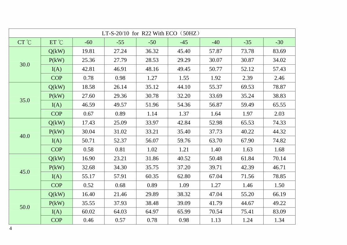
4
LT-S-20/10 for R22 With ECO(50HZ)
CT ℃ ET ℃ -60 -55 -50 -45 -40 -35 -30
30.0
Q(kW) 19.81 27.24 36.32 45.40 57.87 73.78 83.69
P(kW) 25.36 27.79 28.53 29.29 30.07 30.87 34.02
I(A) 42.81 46.91 48.16 49.45 50.77 52.12 57.43
COP 0.78 0.98 1.27 1.55 1.92 2.39 2.46
35.0
Q(kW) 18.58 26.14 35.12 44.10 55.37 69.53 78.87
P(kW) 27.60 29.36 30.78 32.20 33.69 35.24 38.83
I(A) 46.59 49.57 51.96 54.36 56.87 59.49 65.55
COP 0.67 0.89 1.14 1.37 1.64 1.97 2.03
40.0
Q(kW) 17.43 25.09 33.97 42.84 52.98 65.53 74.33
P(kW) 30.04 31.02 33.21 35.40 37.73 40.22 44.32
I(A) 50.71 52.37 56.07 59.76 63.70 67.90 74.82
COP 0.58 0.81 1.02 1.21 1.40 1.63 1.68
45.0
Q(kW) 16.90 23.21 31.86 40.52 50.48 61.84 70.14
P(kW) 32.68 34.30 35.75 37.20 39.71 42.39 46.71
I(A) 55.17 57.91 60.35 62.80 67.04 71.56 78.85
COP 0.52 0.68 0.89 1.09 1.27 1.46 1.50
50.0
Q(kW) 16.40 21.46 29.89 38.32 47.04 55.20 66.19
P(kW) 35.55 37.93 38.48 39.09 41.79 44.67 49.22
I(A) 60.02 64.03 64.97 65.99 70.54 75.41 83.09
COP 0.46 0.57 0.78 0.98 1.13 1.24 1.34

5
LT-S-20/10 for R22 With ECO(60HZ)
CT ℃ ET ℃ -60 -55 -50 -45 -40 -35 -30
30.0
Q(kW) 23.98 32.96 43.94 54.93 70.03 89.27 101.26
P(kW) 30.18 33.07 33.95 34.85 35.78 36.74 40.48
I(A) 50.94 55.83 57.31 58.84 60.41 62.02 68.34
COP 0.79 1.00 1.29 1.58 1.96 2.43 2.50
35.0
Q(kW) 22.49 31.63 42.50 53.36 67.00 84.13 95.43
P(kW) 32.84 34.94 36.63 38.32 40.09 41.94 46.21
I(A) 55.45 58.98 61.84 64.69 67.67 70.80 78.01
COP 0.68 0.91 1.16 1.39 1.67 2.01 2.07
40.0
Q(kW) 21.09 30.36 41.10 51.84 64.11 79.29 89.93
P(kW) 35.75 36.91 39.52 42.13 44.90 47.87 52.74
I(A) 60.35 62.32 66.72 71.12 75.81 80.81 89.04
COP 0.59 0.82 1.04 1.23 1.43 1.66 1.71
45.0
Q(kW) 20.45 28.08 38.55 49.03 61.08 74.82 84.87
P(kW) 38.89 40.82 42.54 44.27 47.25 50.44 55.58
I(A) 65.65 68.91 71.82 74.73 79.77 85.15 93.83
COP 0.53 0.69 0.91 1.11 1.29 1.48 1.53
50.0
Q(kW) 19.84 25.97 36.17 46.37 56.92 66.80 80.09
P(kW) 42.31 45.13 45.80 46.52 49.73 53.15 58.57
I(A) 71.42 76.19 77.31 78.53 83.95 89.74 98.88
COP 0.47 0.58 0.79 1.00 1.14 1.26 1.37

6
11.2 R404A
LT-S-83/41 for R404A WITH ECO(380V 50HZ)
CT ℃ ET ℃ -60 -55 -50 -45 -40 -35 -30
30.0
Q(kW) 88.26 114.26 151.28 192.53 252.12 324.11 350.19
P(kW) 103.69 110.33 112.58 119.33 127.65 135.07 142.88
I(A) 184.78 194.34 200.86 207.95 219.53 229.09 241.05
COP 0.85 1.04 1.34 1.61 1.98 2.40 2.45
35.0
Q(kW) 77.70 104.57 134.61 172.32 221.01 281.65 303.34
P(kW) 113.00 115.34 120.79 124.52 135.93 145.38 155.97
I(A) 146.97 194.72 203.92 217.66 229.47 245.44 263.31
COP 0.69 0.91 1.11 1.34 1.63 1.94 1.94
40.0
Q(kW) 70.29 102.84 131.86 163.56 201.33 244.77 266.36
P(kW) 120.52 125.65 131.71 138.93 147.34 156.82 167.76
I(A) 203.46 212.12 222.35 234.55 248.73 264.75 283.22
COP 0.58 0.82 1.00 1.18 1.37 1.56 1.59
45.0
Q(kW) 66.57 90.20 125.92 157.84 194.49 236.38 258.92
P(kW) 132.61 137.89 144.38 151.52 160.39 170.29 181.55
I(A) 223.87 232.79 243.75 255.79 270.77 287.49 306.50
COP 0.50 0.65 0.87 1.04 1.21 1.39 1.42
50.0
Q(kW) 67.73 83.72 113.11 152.66 178.10 215.16 248.87
P(kW) 158.89 165.47 165.83 174.03 183.50 194.09 203.59
I(A) 266.89 272.93 282.74 294.96 278.85 294.84 309.28
COP 0.44 0.51 0.68 0.88 0.97 1.11 1.22

7
LT-S-83/41 for R404A WITH ECO(380V 60HZ)
CT ℃ ET ℃ -60 -55 -50 -45 -40 -35 -30
30.0
Q(kW) 106.80 138.25 183.05 232.96 305.07 392.17 423.73
P(kW) 123.39 131.29 133.97 142.00 151.90 160.73 170.02
I(A) 219.89 231.26 239.03 247.46 261.24 272.62 286.85
COP 0.87 1.05 1.37 1.64 2.01 2.44 2.49
35.0
Q(kW) 94.02 126.53 162.88 208.51 267.42 340.79 367.04
P(kW) 134.47 137.26 143.74 148.18 161.75 173.01 185.60
I(A) 174.90 231.72 242.67 259.02 273.07 292.07 313.33
COP 0.70 0.92 1.13 1.41 1.65 1.97 1.98
40.0
Q(kW) 85.05 124.44 159.55 197.90 243.60 296.17 322.29
P(kW) 143.42 149.52 156.73 165.33 175.33 186.62 199.64
I(A) 242.12 252.42 264.60 279.11 295.99 315.06 337.03
COP 0.59 0.83 1.02 1.20 1.39 1.59 1.61
45.0
Q(kW) 80.55 109.14 152.36 190.99 235.34 286.02 313.30
P(kW) 157.80 164.09 171.82 180.30 190.86 202.65 216.05
I(A) 266.40 277.02 290.06 304.39 322.22 342.11 364.73
COP 0.51 0.67 0.89 1.06 1.23 1.41 1.45
50.0
Q(kW) 81.96 101.31 136.86 184.72 215.50 260.35 301.14
P(kW) 189.08 196.91 197.33 207.09 218.36 230.96 242.27
I(A) 317.60 324.78 336.46 351.00 331.83 350.86 368.04
COP 0.43 0.51 0.69 0.89 0.99 1.13 1.24

8
LT-S-30/12 for R404A WITH ECO(380V 50HZ)
CT ℃ ET ℃ -60 -55 -50 -45 -40 -35 -30
30.0
Q(kW) 37.92 46.32 56.75 71.18 86.31 107.09 124.82
P(kW) 35.86 39.17 39.30 41.00 43.27 44.44 51.17
I(A) 60.53 66.13 66.34 69.22 73.05 75.02 86.39
COP 1.06 1.18 1.44 1.74 1.99 2.41 2.44
35.0
Q(kW) 33.45 42.16 52.86 66.49 79.91 98.50 115.33
P(kW) 39.21 41.58 42.43 45.13 48.53 50.81 58.50
I(A) 66.20 70.20 71.63 76.19 81.93 85.77 98.76
COP 0.85 1.01 1.25 1.47 1.65 1.94 1.97
40.0
Q(kW) 31.09 40.09 50.45 63.31 74.86 90.82 106.28
P(kW) 42.74 44.00 46.03 49.86 54.68 58.27 67.18
I(A) 72.15 74.28 77.71 84.18 92.31 98.38 113.42
COP 0.73 0.91 1.10 1.27 1.37 1.56 1.58
45.0
Q(kW) 29.06 35.72 45.57 58.29 69.49 83.49 99.76
P(kW) 46.85 49.03 50.03 52.80 58.04 62.02 71.54
I(A) 79.10 82.76 84.45 89.14 97.99 104.71 120.78
COP 0.62 0.73 0.91 1.10 1.20 1.35 1.39
50.0
Q(kW) 27.12 31.77 41.11 53.12 62.55 72.14 89.19
P(kW) 51.69 55.12 54.51 56.42 62.09 66.28 76.55
I(A) 87.26 93.05 92.02 95.24 104.83 111.89 129.23
COP 0.52 0.58 0.75 0.94 1.01 1.09 1.17
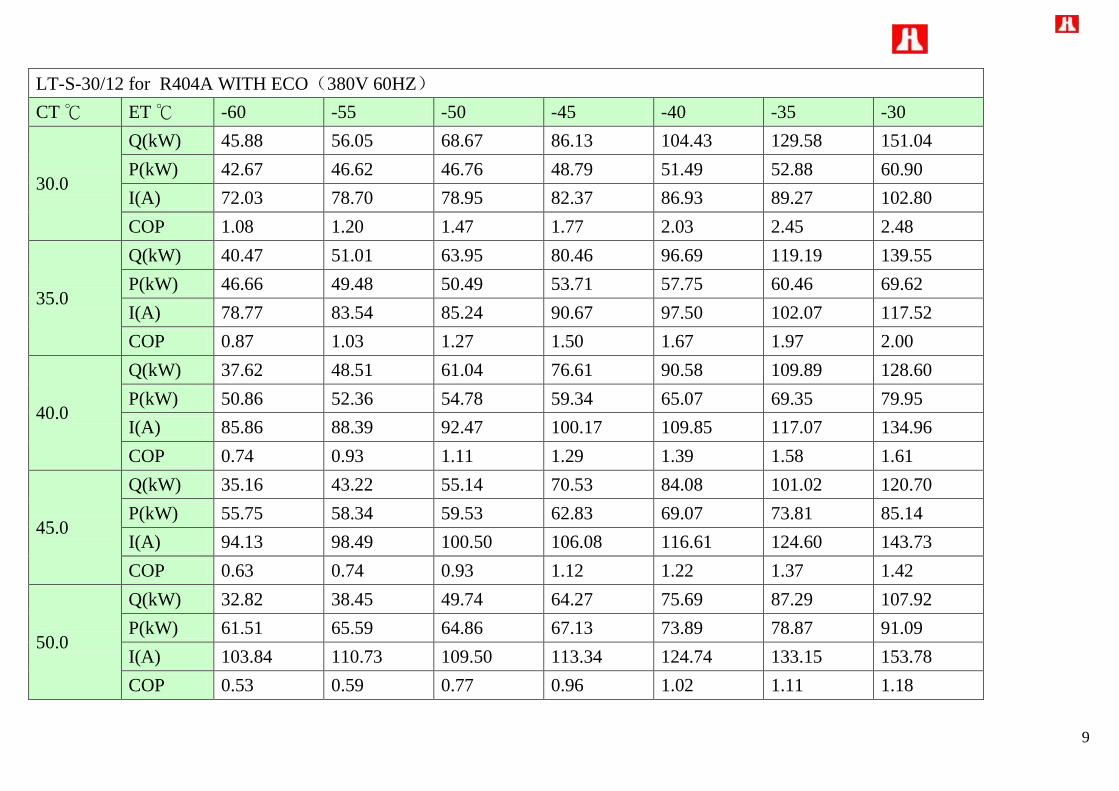
9
LT-S-30/12 for R404A WITH ECO(380V 60HZ)
CT ℃ ET ℃ -60 -55 -50 -45 -40 -35 -30
30.0
Q(kW) 45.88 56.05 68.67 86.13 104.43 129.58 151.04
P(kW) 42.67 46.62 46.76 48.79 51.49 52.88 60.90
I(A) 72.03 78.70 78.95 82.37 86.93 89.27 102.80
COP 1.08 1.20 1.47 1.77 2.03 2.45 2.48
35.0
Q(kW) 40.47 51.01 63.95 80.46 96.69 119.19 139.55
P(kW) 46.66 49.48 50.49 53.71 57.75 60.46 69.62
I(A) 78.77 83.54 85.24 90.67 97.50 102.07 117.52
COP 0.87 1.03 1.27 1.50 1.67 1.97 2.00
40.0
Q(kW) 37.62 48.51 61.04 76.61 90.58 109.89 128.60
P(kW) 50.86 52.36 54.78 59.34 65.07 69.35 79.95
I(A) 85.86 88.39 92.47 100.17 109.85 117.07 134.96
COP 0.74 0.93 1.11 1.29 1.39 1.58 1.61
45.0
Q(kW) 35.16 43.22 55.14 70.53 84.08 101.02 120.70
P(kW) 55.75 58.34 59.53 62.83 69.07 73.81 85.14
I(A) 94.13 98.49 100.50 106.08 116.61 124.60 143.73
COP 0.63 0.74 0.93 1.12 1.22 1.37 1.42
50.0
Q(kW) 32.82 38.45 49.74 64.27 75.69 87.29 107.92
P(kW) 61.51 65.59 64.86 67.13 73.89 78.87 91.09
I(A) 103.84 110.73 109.50 113.34 124.74 133.15 153.78
COP 0.53 0.59 0.77 0.96 1.02 1.11 1.18

10
LT-S-20/10 for R404A WITH ECO(50HZ)
CT ℃ ET ℃ -60 -55 -50 -45 -40 -35 -30
30.0
Q(kW) 23.38 31.60 41.27 50.84 63.66 79.68 89.29
P(kW) 28.52 31.25 32.08 32.94 33.82 34.72 38.21
I(A) 48.15 52.76 54.16 55.61 57.09 58.62 64.51
COP 0.82 1.01 1.29 1.54 1.88 2.29 2.34
35.0
Q(kW) 20.63 28.76 38.43 47.50 58.94 73.29 82.50
P(kW) 31.19 33.18 34.64 36.26 37.93 39.70 43.68
I(A) 52.65 56.01 58.48 61.21 64.03 67.02 73.75
COP 0.66 0.87 1.11 1.31 1.55 1.85 1.89
40.0
Q(kW) 19.17 27.35 36.68 45.22 55.21 67.57 76.03
P(kW) 33.99 35.10 37.58 40.06 42.74 45.53 50.17
I(A) 57.39 59.26 63.44 67.63 72.15 76.87 84.69
COP 0.56 0.78 0.98 1.13 1.29 1.48 1.52
45.0
Q(kW) 17.92 24.37 33.14 41.64 51.25 62.12 71.36
P(kW) 37.27 39.11 40.84 42.42 45.37 48.46 53.42
I(A) 62.91 66.03 68.95 71.61 76.59 81.82 90.19
COP 0.48 0.62 0.81 0.98 1.13 1.28 1.34
50.0
Q(kW) 16.72 21.67 29.89 37.94 46.14 53.67 63.80
P(kW) 41.11 43.97 44.50 45.32 48.53 51.79 57.16
I(A) 69.41 74.24 75.13 76.52 81.93 87.43 96.50
COP 0.41 0.49 0.67 0.84 0.95 1.04 1.12

11
LT-S-20/10 for R404A WITH ECO(60HZ)
CT ℃ ET ℃ -60 -55 -50 -45 -40 -35 -30
30.0
Q(kW) 28.29 38.23 49.93 61.52 77.03 96.41 108.04
P(kW) 33.94 37.19 38.18 39.20 40.25 41.32 45.47
I(A) 57.29 62.79 64.46 66.18 67.94 69.76 76.77
COP 0.83 1.03 1.31 1.57 1.91 2.33 2.38
35.0
Q(kW) 24.96 34.80 46.50 57.47 71.32 88.68 99.82
P(kW) 37.11 39.48 41.22 43.15 45.14 47.24 51.98
I(A) 62.66 66.65 69.59 72.84 76.20 79.75 87.76
COP 0.67 0.88 1.13 1.33 1.58 1.88 1.92
40.0
Q(kW) 23.20 33.09 44.39 54.72 66.81 81.76 91.99
P(kW) 40.45 41.77 44.72 47.67 50.86 54.18 59.70
I(A) 68.29 70.52 75.50 80.48 85.86 91.47 100.78
COP 0.57 0.79 0.99 1.15 1.31 1.51 1.54
45.0
Q(kW) 21.68 29.48 40.10 50.38 62.02 75.16 86.34
P(kW) 44.35 46.54 48.60 50.48 53.99 57.67 63.57
I(A) 74.87 78.58 82.05 85.22 91.14 97.36 107.33
COP 0.49 0.63 0.82 1.00 1.15 1.30 1.36
50.0
Q(kW) 20.24 26.23 36.17 45.91 55.82 64.94 77.20
P(kW) 48.92 52.33 52.96 53.93 57.75 61.63 68.02
I(A) 82.59 88.34 89.40 91.05 97.50 104.04 114.84
COP 0.41 0.50 0.68 0.85 0.97 1.05 1.13