*. t · "mcdonnell douglas corporation ')oit.las aircraft company 2 long, beach,...
TRANSCRIPT

. ,,SA Contracti' Report 165850S,">.AA 11'ýport No. VL)T-FAR-CT-8Z-T0
i0 u;
S'0/3!D35"
*. T -ansport Aircraft Accident Dynamics
Reproduced FromSrt -4Best Available Copy
A. Cominsky DTIC
APR 131984"McDonnell Douglas Corporation')oit.las Aircraft Company 2Long, Beach, California 90846
CONTRACT NASI-16111 DOY LIr•,Ry: MARCH 1982 10A TECH RE7PORT tP,:r.AS INDEP•,.O'N 4 VE SW
CTON, Dc 20.591
rl' Wonil Aeronautics and DEPARTMENT OF TRANSPORTATION"" CI ice Administration Federal Aviation Administration"Lf"n';!oy Roserch Coutor Federal Aviation Technical Center•Hampton.Viraina 23665 Atlantic City, New Jersey 08405
84 04-. ,

NASA Contractor Report
FAA Report No. Dbr-MA -C7 ,-70
TRANSPORT AIRCRAFT. ACCIDENT DYNAMICS
I
A. COMINSKY, et al
Douglas Aircraft Company
McDonnell Douglas Corporation
Long Beach, California 90846 I
CONTRACT NASI-16111 *1March 1982 m
Natioaal Aeronautics and
Space Administration
Langley Research Center, lHampton, Virginia 23665
AC804 827-3966

r
PREFACE
"This report was prepared by the Douglas Aircraft Company, McDonnell Doulqas
Corporation, Lonq Beach, California, under Contract NAS1-16111. It is thefinal technical report covering the review of survivable transport aircraft
accidents, the association between structural systems and accident injuries
and the identification of typical scenarios. This report also includes areview of the five volumes of the "Aircraft Crash Survival Design Guide", anoverview of crash testing techniques and' test recommendations, an overview and
recomm.endations for analytical techniquer and advanced material usage. This* work was conducted between February 11, 1980 and May 26, 1981.
V The following Oouglas personnel were the principal contributors to the study:
J
E. Albano Crash Analysis and Test
A. Cominsky Principal InvestigatorJ. Gaume Human FactorsH. Leve Crash Analysis
M. Platte Systems Analysis
H. Toellner Advanced Materials
R. Reibold Testing
The project was sponsored by the National Aeronautics and Space Administration
(NASA), Langley Research Center. Dr. Robert G. Thompson was the project
englneer for NASA.
DTIF" T'
A..
N
J . . . . t . . . . . -

TABLE OF CONTENTS
SECTION PAGE
List of References xlii• ~~1.0 Introduction .... . . . . .. . . ... .-
S~2.0 S ummary ... . ...... . .. . . . . . ... 2-1
3.0 Conclusions and Recomnmendations ................ 3-1
4.0 Accident Data Base ...................... 4-1
P! 5.0 Characteristics of Accident Scenario Candidates ........ 5-1
6.0 Generalized Impact Scenarios . . . .. . . . . . . . . . . . . 6-16.1 Generalized Landing Mode Accident Scenario6.2 Generalized Rejected Takeoff Mode Accident Scenario
7.0 Assessment of Advanced Materials ........... 7-17.1 Survey of Advanced Materials and Proces~se7.2 Aluminum Alloys7.3 Metal Matrix Materials7.4 Advanced Composites.75 New Processes7.6 Test Recommendations for Advanced Composites
A 8.0 Evaluation of the "Aircraft Crash Survival Design Guide" . . . 8-1
Conclusions
9.0 human Tolerance to Impact . c..... 9-1
10.0 Merit Functions ........................ 10-1
11.0 Analytical Methods ................... . . . 11-111.1 Analytical Requirements11.2 Review of Existing Analysis Programs11-3 Analysis Recommendations
12.0 Test Methods . . . . . . . . . . . . . . . . 0 0 0 0 . . 12-112.1 Review of Past Test Programs12.2 Recommendations for Future lests
".-4
A
v

* l ABLE OF CONTENTS (Cont)
SECTION PAGE
APPENDIX A Accident Data Base . . . . . . . . . . . . . . . ... A-i
APPENDIX B Scenario Candidates Accident Characteristics . . . ... . B-i
APPEND!X C DC-7 Impact Test ................... . C-iSAPPENDIX D Test Program .. . .. ... . . . . ... D-1
APPENDIX E Review of the "Aircraft Crash Survival Design Guide" . . E-1
APPENDIX!F Human Tolerance to Impact . . . . . . . . . . ... . F-i
Vi
t-

/
ILLUSTRATIONS
NO. TITLE PAGE
D-1 Landing Gear/Wing Drop Test D-3D-2 Fuselage, Static Crush Test D-5"D-3 Fuselage Drop Test D-5D-4 Fuselage Break Test D-5D-5 Data Acquisition Set-Up for Impact Tests 0-10D-6 Functional Diagram - Load and Motion Control D-12
, D-7 Functional Diagram - Data Acquisition D-13
" E-1 Typical Seat Pan, Dummy Chest and Pelvis Response E-9"E-2 Method of Reinforcing Nose Structure E-12E-3 Overall Fuselage Concepts E-14E-4 Fuselage Sidewall Concepts E-15E-5 Energy Absorption Concepts E-16E-6 Examples of Engergy Absorption Devices E-17E-7 Stress-Strain Relationship E-18E-8 Energy Absorption Concepts - Beams E-20E-9 Aircraft Troop/Passenger Restraint Systems E-22E-1O Aircraft Floor Longitudinal Pulses E-25E-11 Seat Forward Load and Deflection Requirements E-27E-12 Load-Displacement Requi rements for Cargo E-28E-13 Requirements for Dynamic Tests E-29
F-1 Experimental Verfication of Dynamic Index F-4F-2 Wayne State Tolerance Curve for Forehead Impact F-7F-3 Acceleration Limit (+GxL) F-11F-4 Superposition of-Shock Spectra and Human Tolerance,- F-13F-S Impact G Tolerance as a Function of Age F-1S
Ivii
i vii

• - .A -J-•. F -.- -J-. -. , -. 1.) 1%hJ 11; 1. •, .• • •' ',• • •~',•Jb• , -. a
TABLES
NO. TITLE PAGE
4-1 Accident Category Identification 4-3
4-2 Tenerife Accident Casualty Statistics 4-34-3 Injury Survey, 1960-1980 Commercial Transports 4-4
5-1 Accident Scenario Characteristics Groups 5-25-2 Approach Accidents Characteristics and Injuries 5-35-3 Landing Aczidents Characteristics and Injuries 5-45-4 RTO. Accidents Characteristics and Injuries 5-5
6-1 Generalized Crash Scenario Elements 6-26-2 Off Runway Obstructions, Landing Mode Accidents 6-46-3 On Runway O.bstructions, Landing Mode Accidents 6-56-4 Aircraft Structural Damage, Landing Mode Accidents 6-6
SA-I Approach Accioents Data Base A-2A-2 Landing Accidents Data Bdse A-4A-3 Rejected Takeoff Accident Data Base A-7
B-I Approach Accidents - Characteristics and Injuries B-2B-2 Landing Accidents - Characteristics and Injuries B-88-3 Takeoff A'cidents - Characteristics and Injuries B-20
E-1 Performance Requirements for Structural Impact Tolerance E-4E-2 Summary of Crash Impact Conditions for Helicopters and E-5
Light Fixed Wing AircraftE-3 Static Load Requirements for Ancillary Equipment E.31
Attachments
a.
N,
S.
ix
00

LIST OF ABBREVIATIONS
NTSB National Transport Safety Board
SOLARAD System of On-Line Analysis Retrieval of Accident Data
.RTO Rejected Takeoffa
GIS Generalized Impact Scenario
VRGA Relative Ground Airspeed Velocity
IATA International Air Transport Association
MAD International Civil Air Organization
I
i6
16
xii
'I
LIS OFABBEVIAION

:P p
LIST OF REFERENCES.NO.
Aircraft Crash Survival Design Guide (VOLUMES I-V)1 VOL. I USARTL-TR-79-22A
Design Criteria and Checklists
2 VOL. II USARTL-TR-79-22BAircraft Crash Environment and human Tolerance
3 VOL. III USARTL-TR-79-22CAircraft Structural Crashworthiness
VOL. IV USARTLTR7922D
Aircraft Seats, Restraints, Litters, and Padding
5 VOL. V USARTL-TR-79-22EAircraft Post Crash Survival
6 Applicaticn of Scale Modeling Techniquesto Crashworthiness Research.Aircraft Crashworhhiness - K. SaczalskiUniversity ot Virginia Press 1975
7 Crash Loads Environment StudyDonald P. Fitzgibbon, Feb. 1967
4• Mechanics Research, Inc., El Segundo, California
8 NASA Report 165677
9 R. F. Chandler, D. H. Laananen, "Seat/Occupant CrashDynamic Analysis Verific~ation Test Program",SAE Paper No. 790590, April 1979
1 10 R.J.Hayduk, R. G. Thornon, G. Wittlin, M. P. Kamat,
"Nonlinear Structural Crash Dynamics Analyses",SAE Paper No. 790588, Ap ]1 1979
1D. H. Laananen, J. W. Col man, "Modification andExperimental Validation o Program SOMLA",SIMULA Report No. TR8005, pril 11, 1980
12 D. H. Laananen, "Developme t of a Scientific Basisfor Analysis of Aircraft. Seating Systems",FAA-RD-74-130, 1975
13 M. A. Gamon, "General Aviation Airplane StructuralCrashworthiness User's Manual: Volume I - ProgramKRASH Theory", FAA-RO-77-189, I, February 1978
xiiiSx11
LIST OF REFERENCLS
:, NO.
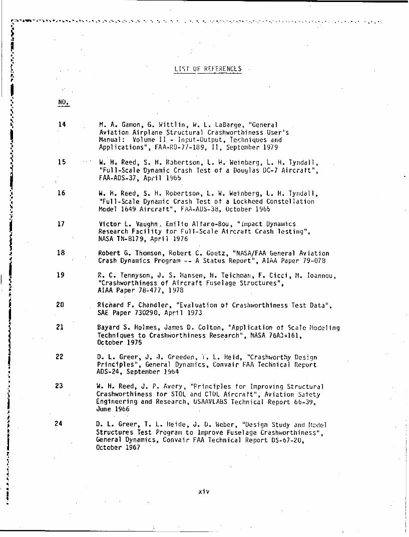
14 M. A. Gamon, G. Wittlin, W. L. LaBarge, "GeneralAviation Airplane Structural Crashworthiness User's.Manual: Volume II - Input-Output, Techniques and"Applications", FAA-RD-77-189, II, September 1979
15 W. H. Reed, S. H. Ribertson, L. W. Weinberg, L. H. Tyndall,"Full-Scale Dynamic Crash Test of a Douglas DC-7 Aircratt",FAA-ADS-37, April 1965
16 W. H. Reed, S. H. Robertson, L. W. Weinberg, L. H. Tyndall,"Full-Scale Dynamic Crash Test of a Lockheed ConstellationModel 1649 Aircratt", FAA-ADS-38, October 1965
17 Victor L. Vaughn., Emilio Alfaro-Bou, "Impact DynamicsResearch Facility for Full-Scale Aircraft Crash lestirig",NASA TN-8179, April 1976
18 Robert G. Thomson, Robert C. Goetz, "NASA/FAA General AviationCrash Dynamics Program -- A Status Report", AIAA Paper 79-078
19 R. C. Tennyson, J. S. Hansen, H. Teichman, F. Cicci, M. Ioannou,S"Crashworthiness of Aircraft Fuselage Structures",
AIAA Paper 78-477, 1978
20 Richard F. Chandler, "Evaluation of Crashworthiness Test Data",SAE Paper 730290. April 1973
21 Bayard S. Holmes, James D. Colton, "Application of Scale Modeling
Techniques to Crashworthiness Research", NASA 76A34161,October 1975
22 D. L. Greer, J. .1. Greeden, T. L. Heid, "Crashworthy DesignPrinciples", General Dynamics, Convair FAA Technical ReportADS-24, September 1,964
23 W. H. Reed, J. P. Avery, "Principles for Improving StructuralCrashworthiness for STOL and CTOL Aircratt", Aviation SatetyEngineering and Research, USAAVLABS Technical Report 66-39,
EJune 1966
24 D. L. Greer, T. L. Heide, J. D. Weber, "Design Study and ficdelStructures Test Program to Improve Fuselage Crashworthiness",
.I General Dynamics, Convair FAA Technical Report DS-67-20,t October 1967
V
_! xi v

SECTION 1
INTRODUCTION
The United States is a leader in the design and production of large conmmercialaircraft. The ai~craft produced by the aircraft industry have been improved
continuously because of the industry's concern fcr reliability and safety.
Government regulatory and research activities share in the interest of
impove sevics ad icresedsafety for the public.
The purpose of this study was to investigate transport impact tolerance and to
study the possibility of improving passenger and crew safety in transport
aircraft. The structural integrity of the fuselage during a survivable impact
was the primary concern.
The modern commercial aircraft requires maximum safety; however, new
protective features must be justified by an increased level of safety with a
minimum of added complexity, weight and operational constraints.
During the period 1959-1979, there were approximately 580 worldwide transportaircraft accidents which provided the source of the data base for this study.
This study tended to confine itself to an examinatlon of the modern jet of
27,200 kg (60,000 lb.) and up and non-turbulence, survivable accidents.
¶Thus, only approach, landing and rejected takeoff accidents were studied.These comprise 60% of all accidents which occurred in about 6% of the total
operational time. The data base of this study is given in Appendix A in which
Teda~ta base was examined ani summarized in Section 6 and Appendix B.Typical accident scenarios were developed from this data for possible use as
future design a.ad test instruments.

P Advanced materials and processes are playing increasing roles in f'.ure"transport designs. Their potential impact properties are discussed, and steps
needed to fill in the gaps in impact tolerance applications are suggested.
An evaluation of the "U. S. Army Aircraft Crash Survival Design Guide" was
carried out to determine possible application to airline transport aircraft.
"Various indices and criteria for relating impact acceleration with human
tolerance with the intention of judging human survival Vere studied and
evaluated.
- .- A review of impact scenarios from the data base was carried out to identify
major structural components which were involved in typical accidents.
Existing analytical techniques were evaluated and suggestions put forward for
developing simple, economical and possibly more accurate pre:edures.Established test techniques were reviewed and a test program was outlined for
providi•dq data to assist in the development of simplified analysis techniques.
"SV ItIb''
1-2

SECTION 2
$ SUMMARY
Format - 2.1 Data Base and Scenario Candidates2.2 Characteristics -of Scenario Candidates
2.3 Generalized Impact Scenarios
2.4 Advanced Materials Assessment
2.5 Aircraft Crash Survival Design Guide
2.6 Human Tolerance to Impact
2.7 Merit Functions
2.8 Analyt ical Methods
2.9 Test Methods
2.1 DATA BASE AND SCENARIO CANDIDATES
The accident data base for this study consists of 112 Impact survivable
transport aircraft accidents (world wide) that are listed in Appendix A.These were principally jet transport aircraft of 27,200 kg (60,000 lb.)and up. This study centered on the effect of impact on aircraftstructurtr. Thus, the study was confined to approach, landing and takeofffl ight segmients. Accidents confined to flight turbulence, taxiing andparking were eliminated.
2.2 CHARACTERISTICS OF SCENARIO CANDIDATES
The well1 documiented accidents were studied to record significant
characteristics, their frequency of occurrence, and effcct on passengerinjury. The details resulting from this review are listed in the three
tables of Appendix B.
It was concluded that the condition of the fuselage shell and the cabininterior had a direct bearing on passenger impact injury. Other factorssuch as engine separation, landing gear separation and wing tank rupture
W were important because they led to fuel spill and a fuel fed fire whichwas a prime threat to passengers.
2-1

2.3 GENERALIZED IMPACT SCENARIOS
Generalized Impact Scenari,3s (GIS). are presented for landing and
rejected takeoff accident categories. 'These scenarios wer.., developed
J from~ data averages as well as from typical accidents and-are confined to
that data which affects the behavior of the structure during impact.
The Generalized Landing Mode Scenario .consists of meteorological data
and a description of the aircraft from just prior to impact through the
slide to when the wreckage comes to a halt. This scenario contains two
divisions:
A) Touchdown short of the runway
B) Touchdown on the runway
The Generalized Rejected Takeoff Mode Scenario consists of
meteorological data and a description of the aircraft from the beginning
of the takeoff roll through the runway overrun to when the wreckage
comes to a halt. This scenario contains three divisions:
A) Lnhuwa vruA) Shong runway overrun
C) Halted on the airport
2.4~ ASSESSMENT OF ADVANCED MATER IALS
An assessment of advanced structural' materials and advanced fabrication
processes was made in Section 7. The materials were grouped into three
categories:
1. Alumninum Alloys
2. Metal Matrix Materials
3. Advanced Composites
2-2
The 'processes were grouped into five categories:
1.. Bonding
2. Diffusion Bonded/Superplastic Formed Titanium
3. Large Castings
4. Filament Winding
5. Trappe" Rubber
p
Bcnetits and limitations of these materials and processes were discussed
and attention was drawn to those materials and processes with
substantial future promise.
2.5 AIRCRAFT CRASH SURVIVAL DESIGN GUIDE
This Desigr Guide comes in five volumes which are numbers 1 through 5 in
the List of References. These reports present the state-of-the-art for
impact survival design for use in design of army helicopters and
lightweight general aviation aircraft. These reports were reviewed to
determine possible application to transport aircr3ft design.
2.6 HLUIAN TOLERANCE TO IMPACT
A survey was carried out of many indices and criteria that have been
proposed for giving an indication of the degree of passenger injury
during an impact sequence. Thz2se indices apply to spine, head, leg and
arm injuries.. This type of data is important to the evaluation of
impact tolerance of future transport aircraft designs.
2.7 MERIT FUNCTIONS
The n,,rit function evaiuation is a useful method for comparing the
degree of merit of ccmpeting s;fety concepts. The parameters that are
useful for evaluating the merit function fall into three categories:
cost, effectiveness and socletal concerns. The elements of these
parameters are described within.
ro
2.,
9.:
2-3:

2.8 ANALYTICAL METHODS
Considerable Research and Development is being carried on within NASA
and the aircraft manufacturing companies toward deve.oping computer
analyses capable of describing the dynamic behavior of an aircraft
(including structural deformation, acceleration, stresses and failure,
as -we as the forces and accelerations acting on the passengers and
crew) subjected to an impact sequence of an accident scenario.
A review of three such computer analysis programs is presented in
Section 11.0. These were the Krash, Dycast and Somla programs. Krash
models the aircraft structure as a system of masses, springs and
dashpots. This analysis method is well documented and is potential.,
well suited to describe large aircraft impact sequence simulation.
Dycast models the aircraft structure in great detail as a number of
finite elements, but its size may render it too complex for complete
aircraft usage. It may, however, be very useful for application to
local portions of a structure.
Somla confines its analysis to the occupant and seat structure. Theoccupant is a mass/spring/dashpot system while the seat is modelled by a
finite element system and works quite well.
Comments on analytical requirements and recommendations of impactanalysis programs are also presented.
2.9 TEST METHODS
This section consists of a review of full scale aircraft structure
impact type tests that have already been carried out. This section alscdeals with recommendations for future tests.
2-4

There are two Iul1 scale large transport aircraft impact tests that were
carried out sixteen years ago. These consisted of a DC7 and a Lockheed
Constellation, both propeller powered aircraft. The aircraft structure,
equipment and dummies were well instrumented, and the resulting test
data was very significant. The remainder of the tests and the resultsJý 0were only Available for light general aviation aircraft and hielicopters.
The. objectives of future tests are considered to be:
1) Verify the accurar.y of existing impact analysis programs
2) Provide impact data results for several sizes of aircraft
3) Orovide data for use in developing simplified analysis
methods of impact scenarios
4) Help to establ~ish the impact capabilities of existing metal
jet aircraft to establish levels of excellence for future
advanced composite aircraft structures5) Test out structural improvements by which impact tolerance
could be improved.,
A recommended test program to be carried out in the future is described
in Section 12.0. Five categories of tests were described with the
conclusion that:
Testing of structural subsystems could provide needed test
results at economical costs. An extensive test program
involving the use of structural subsystem specimens
obtained from salvage sources is suggested to provide data
for recommended follow on studies.
2-5

SECTION 3
CONCLUSIONS AND RECOMMENDATIONS
Format - 3.1.0 Conclusfons
3.2.0 Recommendations
3.2.1 Scenario Candidatesi3.2.2 Advanced Materials
3.2.3 U.S. Army Aircraft Crash Survival Design Guide
3.2.4 Human Tolerance To Impact
3.2.5 Analytical Methods3.2.6 Test Methods
3.1.0 CONCLUSIONS
The conclusions resulting from this study are:
1) The limited number of domestic and foreign transport
aircraft survivable accidents and related passengerinjuries over an eighteeni year period (1961-1979) is an
indication of the limited potential for impact tolerance
improvement for metal aircraft.
2) Aircraft impact during the approach flight mode. is
equivalent to the aircraft flying -Into the ground and, as
such, is too severe to constitut..A a practical design goal.
3) There are 50 percent more fire fatalities than impact
trauma fatalities for survivable landing and takeoff mode
accidents. Thus, post impact fire accidents are prime,
candidates for survivability improvement studies.
3-1-

/, /
4) Nineteen out of forty-five survivable accidents involved
light to heavy rain during survivable approach, landing and
takeoff maneuvers. The avoidance of heavy rain situations
* especially during final approach and landing would reducethe probability that a pilot will encounter conditions
- which make aircraft control difficult. On-board radar
makes this feasible.
5) Ar-eas for research and development for aircraft impacttolerance improvement are:
o landing gear attachments
o engine attachmento wing tank structure
o fuselage structure and equipment
6) The "U. S. Army Crash Survival Design Guide" (References 1
through 5) provides a unique general aid to impact tolerant
structural design with overwhelming emphasis to helicopters
and light fixed wing aircraft. It is a good source of
design methodology as in the definition of impact conditionsin terms of acceleration versus time pulses (Reference
Figure E-1O). The treatment of design considerations for
impact tolerant seats is comprehensive. A uýeful approachto impact tolerant structural design may be accomplished by
P. expressing static strength requirements in terms of boundson loads versus deformation curves (Reference Figures E-11and E-12).
7) Available data concerning human tolerance to impact is
primarily related to Air Force ejection seat design and9 thus should not be carried over to the transport passenger
• who exhibits a wide range in size, weight, age, physical
condition and degree of restraint.
3-2

*8) It is important that development continue on advanced
impact dynamics analysis programns such as KRASH and DYCASTN particularly in the area of large transport modelling.
IN These will be needed as design assist and design
verification tools.
3.2.0 RECOMMENDATIONS
3.2.1 SCENARI CANDIDATES
The data base consists of 112 impact survivable transport
aircraft accidents which are grouped into three categories,
'liltnamely: approach, landing, and rejected takeoff modes. The
typical approach mode accident occurs as,' the aircraft impacts
the ground while proceeding along the glide slope at approach
speed. This is a very severe accident scenario as can be seen
in Table 4-3, page 4-4. The fire and impact trauma fatalities
4 are the largest of the three accident medes.
It is considered that the typical approach accident is not a.
practical candidate as a basis for aircraft design. The landing
and rejected takeoff scenarios of Section 6 are proposed as
potential scenario candidates which should be subjected to
examination and analysis to determine the practicality of thei magnitudes of the loads, accelerations, impact and failure
sequence which result from these scenarios.
3.2.2 ADVANCED MATERIALS
A survey of advanced materials and processes is given in
Section 7. It is conceded that the new aluminum alloys shouldexhibit similar impact tolerance as aluminums that are in use
today. However, questions about the behavior of metal matrix
and advanted composites in hi-energy impact situations have not
yet been answered.
I3-3

It is recommended that a program shouldi be initiated to study
the following:
1. Post buckling behavior of laminated composite structure
2. Complex failure modes (under impact loading)
3. Kb~terial flammability
4. Thermal decomposition (i.e., noxious gases, smoke
eveluation and human tolerance)
5. Service life degradation prior to an accident.
The program to study the high energy impact tolerance potential
of metal matrix and advanced composites could consist of the
following* steps:
1) Establish practical design composites concepts
2) Analyze the design concepts using material properties3) Fabricate subcomponent specimens
4) Subject the specimens to test
5) Compare the test results with predictions and compare the
impact 4~havior of the candidate materials with the L
baseline aluminum specimens.
The types of tests to be considered for this program are the
following:;J -
A) "Head on collision* for which the specimen would resemble a
secti."t of fuselage
8) "Vertical drop* for which the specimen would resemble the
underbelly of an aircraft
C) "braion*wit a pecien s fo tet 8
C) "Sabrasiong" with a specimen as for test B)
3-4.

TC.,, . iwvnced material candidates for semi-scale testing:
"1. Alt::ninum for basel ine .
S2. Graphite/epoxy composites
Rigidite 5208/T300 for baseline
CI2A 74/T300
BP 907/T300
"3. Thermoplastic resin
Peek resin/T300
'!c!w resin
"4. T.'o polyimide/graphite systems
"5. Kevl ar/epoxy
6. Boron/aluminum
7. Graphite/aluminum
8. Large aluminum castings
3.2.3 U. S. ARMY AIRCRAFT CRASH SURVIVAL DESIGN GUIDE
It is clear that overwhelming, emphasis In the Design Guide is
given to helicopters and to a lesser degree, light fixed wing
aircraft. Therefore, it is recommended that a very worthwhile
effort could consist of developing a commercial transport
aircraft equivalent to the U. S. Army Design Guide.
3.2.4 HL:IAN TOLERANCE TO IMPACT
Since the available human tolerance data is Air Force personnel
oriented, it is recommended that a careful study to establish a
definitive set of injury criteria for transport impact tolerance
application be carried out. This would be an important
contribution toward transport impact tolerance eval-dtion.
3-5V

3.2.5 ANALYTICAL METHODS
It is recommended that workshops should be set up to provide3 opportunity for gaining experience in the use of KRASH, DYCAST
and SOMLA for those that have not participated in their
development.
A significant effort should be devoted to the formulatior of
simplified analysis approaches which *serve preliminary design
and parametric variation study purposes.
One concept to consider is the appli.ation of shaped
acceleration pulses at the base of the occupant's seat. It
would be necessary to first establish a proper set of pulses.
A second concept could involve modelling most of the aircraft by
means of flexible mode shapes. The modol would use non-linearelements below the fuselage floor and could account for moderate
impact pulses. The structural model should contain less than 50
degrees of freedom and the execution CPU time should be less
than 1,000 times real time.
3.2.6 TEST METHODS
It is recommended that a test program be carried out to:
0 Provide basic data for developing simplified methods of*. impact analysis.
0 Verify existing analysis methods and the proposed
"simpl ifled methods.
o Provide knowledge and visual evidence of aircraft structure
failure in progress.
43
3-6
S• h",

Tests performed with structural subsystem specimens provide the
greatest promise for leading to improved impact tolerance.
Structural components of many current aircraft. are available at
a reasonable cost from salvage yards.
The impact tolerance of an aircraft is primarily dependent on
the performance of these three structural components:
1) Landing gear and wing2) Fuselage underbelly
3) Seat and support structure
The types of tests to be performed on these -specimens are listed
and described in Section 12.'..4 and Appendix 0.
LI
,J..4
.3-

a,° • ..a .P-" . ° P-
SECTION 4
ACCIDENT DATA BASE
The accident data base was obtained from
1. NTSB data tapes called the "System of On-Line Analysis Retrieval of
Accident Data (SOLARAD). This computer data bank has accident and
incident data from the period 1964 to 1978 that are categorized and
sorted.
o 2. ICAO and World Airline Accident Summaries
Two listings of jet aircraft accidents were extracted from SOLARAD tapes. One
listing extracted all fatal accidents for Jets of 27200 kg (60,000 lb.) and
"up. This produced an output of 92 accidents. The other listing extracted
accidents with only serious injuries. This produced an output of 297
accidents.U Accidents which involved only minor damage, air turbulence, minor injury or
were non-survivable were discarded. The remaining substantial damage, 4fatal/serious injury accidents comprise the accident data base of 112
accidents and are listed in Appendix A.
An impact-survivable accident in this analysis is defined as an accident in
which all occupants did not receive fatal injuries as a result of impact
forces imposed during the crash sequence. Anl accident is classified as a
fatal accident if one or more occupants received fatal injuries. Substantial
damage is damage which adversely affects the structurtl strength, performance,
a or flight characteristics of the aircraft and which would normally require.4 replacement or major repair unless the accident results in destruction of the
aircraft. Several fatal accidents involving an initial non-fatal occurrence
resulting in substantial damage and a subsequent non-survivable impact orXi fatal event are included in the survivable or non-fatal categories because the
damage resulting from the initial impact was of interest from an impact
tolerance viewpoint and also because the subsequent impact or event might have
:0 been prevented had the effect of the initial damage been minimized.%1
4-1

-" Aircraft accidents occur on or off the airport during a landing, takeoff, taxi
or parked mode. The taxi/park type of accident is generally not very serious
and was eliminated from further consideration, Thus, the accident data baseto be studied was organized into three categories according to the flight mode
of the aircraft prior to the impact. These categories were
S1) Approach
i 2) Landing, 3) Rejected Takeoff (RTO)
Approach accidents occur while the aircraft is descending on approach before
reaching the airport. This flight mode is generally characterized by flight
. along or near the glide slope with approach speed, power, flaps, and gross,
weight with landing gear down. Impact can be with trees, level or sloping
ground, ditch, enmbankcment,' dike, water, vehicles, buildings or light supportstructures. These accidents are numbered 1-1 to 1-114 in Table A-I of
Appendix A.
Landing accidents occur when the aircraft touches down on or near the runway,and overruns or veers off the runway after touchdown. This flight mode is
characterized by flared-ou$ flight with landing speed, power, flaps, and grossweight with landing gear down. These accidents are numbered 2-0 to 2-113 inTable A-2 of Apoendix A.
I Takeoff accidents occur while the aircraft is moving on the runway forý takeoffC or after liftoff prior to retracting the landing gear and flaps. A tire or
engine failure usually occurs. The wheel or engine braking action is thusj reduced and asymmetrical, and the aircraft overruns the airport runway. These
accidents are numbered 3-0 to 3-127 in Table A-3 Appendix A.
The data base in:ludes principally domestic aircraft in the service ofb domestic and foreign airlines. This study applied only to transport category
• aircraft in commercial service certified to FAR PART 25.
S4-2
7-L

c ci"-entation is needed for a useful study of an accident. NTSB has
.-i•;iiction over domestic accidents but not those occurring in foreign
ct-n-rios. NTSB Blue Book accident reports was the principal source of
in{friition for thi- study. Since the availability of good documentation is
so vital to the pursuit of this study, the well documented accidents were
i,,,rtified to reveal this. The identification system is showr in Table 4-1.
S1 ACCIDENT IDENTIFICATIONACCIDENT TOTALCATEGORY WELL BARE NUMBER
DOCUMENTED DOCUMENTATIJN
APPROACH 1-1 TO 1-12 1-101 TO 1-114 26
LANDING 2-0 TO 2-15 2-101 TO 2-113 35
REJECTED 3-0 TO 3-10 3-101 TO 3-127 44TAKEOFF
TOTAL NUMBER 48 57 105
TABLE 4-1: ACCIDENT CATEGORY IDENTIFICATION ANDQUALITY OF DOCUMENTATION
The Teneriffe accident 'March 27, 1977) is not included among the RejectedTdkeoff accidents data base. This accident involved the ground collision of
two Boeing 747 aircraft and is considered as non-survivable due to the
(lestruction of the fuselage shell of both aircraft during the collision. The
casualty figures for this accident are in Table 4-?.
IMPACTI TOTAL NONE/MINOR SERIOUS TRAUMA FIRE
AIRLINE ABOARD INJURY iNJURY FATALITY FATALITY(T) (N/M) (S) (I.T.) (F)
YA M 248 0 0 50 198
PAN AM 396 36 34 134 192
,ABLE 4-2: TENERIFFE ACCIDENT, PASSENGERS AND CREWCASUALTY STATISTICS
4-3

% ~ ~ LS& ~ ~ *- *t b p ,* * .*C
World transport casualty statistics for survivable accidents occurring during
the 1960 to 1980 period are given in Table 4-3.
NUMBERNUMBER OF PASSENGERS AND CREWNUMBER_____________
ACCIDENT OF RNONE SERIOUS FATALITIES ____
GROUP ACCIDENTS TOTAL MINOR IIMPACT_____TOTAL TRAMPA FIRE DROWNING
1. APPROACH 27 2,113 550 287 1035 434 298 0
2. LANDING 33 3,058 1,581 352 421 157 227 0
3. TAKEOFF 49 ,9 3,601 352 379 92 146 78
TOTAL 109 1 0,069 5,732 991 1, 835 683 671 78
FIGURE 4-3:. INJURY SURVEY -SURVIVABLE ACCIDENTS-PERIOD 1960 TO 1980, COMMERCIALI TRANSPORT AIRCRAFT..
'4-

SECTION 5
CHARACTERISTICS OF IMPACT SCENARIO CANDIDATES
*One of the principal objectives. of this study was the. development of
*generalized impact scenarios (GIS) representative of typical survivable
aircraft accidents. The data base chosen for this development was the well
~ . documented accidents identified in Table 4-1.
.1The first step was to extract accident related data to show
1) a list of significant accident characteristics
2) the frequency of occurrence of the significant accident
characteristics.
3) the rel ationshi p between the accident characteristics and the
aircraft occupant injuries.
4) typical or average values for accident characteristics whereI appropriate.
For these purposes, a matrix of impact characteristics derived from the
reference documents listed in Tables B-1, B-2 and B-3 was prepared for each of
the three accident categories; approach, landing and takeoff and are presented
in Appendix B. The approach and landing characteristics matrices (Tables B-1
and B-2) are similar and each contain 94 characteristics arranged in seven
groups shown in Table 5-1.
The rejected takeoff matrix (Table B-3) contains 120 characteristics arranged
in the seven groups also shown in Table 5-1.
5-1

-----------~~~~~*-HARACTRISTI G~* .. .v. ''...ROUP 4*~vb ~,
3___ CPROCAR M ACTE RUNWA ICKOF RUOU
1 PASSEINGR & AICREWT PLD RNASSENGERS U &CE
4 TERRAIN & ~~AIRCRAFT SLIDE RNA VRU
5 METEOROLIGICAL METEOROLOGICAL______ INFORMATION INFORMATION
TABLE 5-1: ACCIDENT SCENARIO CHARACTERISTICS GROUPS
The following data is given in the botton seven rows of each matrix. 5
1) the frequency of occurrence of the significant impact characteristics
2) the numbers of serious injuries, impact and fire fatalities for the
accidents which experienced the given significant impact
characteristic.
This accident frequency and injury data helped to prov de some indication of
the seriousness of each characteristic.
79
5-2

To facilitate the location of the information about an accident characteristic
within the matrix and also to emphasize the importance of time during the fire
and evacuation periods, some of the accident groups are listed chronologi- K. /
cally. These are the third, fourth, fifth and sixth groups of those shown in
Table 5-1.
The approach impact characteristics for thirteen scenario candidates are
recorded in Table B-1. The serious structural failures and related results
are shown in Table 5-2.
NUMBER OF INJURIES FORNUMBER ASSOCIATED ACCIDENTS
STRUCTURE OF SERIOUS FATALITIESACCIDENTS INJURIES IMPACT TRAUMA FIRE
(SO) (I.T.F.) (F.F.)
ENGINE 1i 186 269 182SEPARATION . 7
LANDING GEAR 10 168 163 144SEPARATION
TANK 7 159 257 164RUPTURE
FUSE'AGE 8 136 293 135BREAKS .
SEAT 9 155 275 146FAILURES --
REFERENCE TABLE B-1
TABLE 5-2: APPROACH ACCIDENTS, CHARACTERISTICS & INJURY SUMMARIES X\
5-3

So . .
4i
K- iThe average airspeed equals 146 Kn. and the average rate of descent equals
7.95 ml/s (26.1 fps). There were ten fire accidents associated with
* 146 S.I.'s, 304 I.T.F.'s and 175 F.F.'s.IThe aircraft generally impacts short of the runway by an average of 4485m
(14,716. feet). There was a great variation in the landing terrai'n and
obstacles such as light support structure, wooded ground, buildings,
Sembarkment, dike, trees, marshland and ditch.
The landing category accident characteristics for nineteen scenario candidates
are recorded in Table 8-2 of Appendix B. The serious structural failures and
related injury consequences are given in Table 5-3.
INL.4ER OF INJURIES FORNUMBER ASSOCIATED ACCIDENTS
STRUCTURE I OF SERIOUS FATALITIESACCIDENTS INJURIES IMPACT TRAUIMA FIRE
(SI) (.T.F (F.F.)
ENGINE 12 253 51 206SEPARATION
LANDING GEAR 12 156 13 184SEPARATION
TANK 7 93 58 182RUPTURE
FUSELAGE 9 112 58 115BREAKS
SEAT 7 138 57 45FAILURES
(REFERENCE TABLE B-2)
TABLE 5-3: LANDING CATEGORY ACCIDENTS, CHARACTERISTICS & INJURY SUI4MARIES
5-4
..................................................

The average airspeed equals 135 Kn and the average rate of descent equals 6 m/s
(19.7 fps). In this category, there were 9 fire and 3 explosion accidents.
There were six impacts short of the runway by an average of 549m'
(1,800 feet). Seven of the landing category accidents resulted from runway
overruns after the aircraft touchdown on the runway.
The landing category accident produced markedly less impact trauma fatalities
than does the approach category accident. This probably results from thereduced touchdown speeds of the aircraft at impact.
The rejected takeoff (RTO) category accident characteristics for fourteen
scenario candidates are recorded in Table B-3 in Appendix B. The serious
structural failures and related results are shown in Table 5-4.
* NUMBER OF INJURIES FORNUMBER ASSOCIATED ACCIDENTS
STRUCTURE OF SM100 FATALITIESACCIDENTS INJURIES IMPACT TRAUMA FIRE_-_._.__._ (SI) (I.T.F.) (F.F.)
ENGINE 5 51 5 51SEPARATION
LANDING GEAR 7 140 3 59
* SEPARATION
ITIRE 6 139 3 48FAILURE
TANK 8 138 8 49RUPTURE
FUSELAGE 6 124 8 57BREAKS
SEAT 3 53 7 0FAILURES
TABLE 5-4: RTO CATEGORY ACCiDENT, CHARACTERISTICS & INJURY SUMMARIES
5-5

The average maximum airspeed achieved during the takeoff run was 145 Kn. Due
*to braking procedures, the speeds, however, generally are less than 100 Kn
when the impact occurs.
*Nine RTO accidents involved a runway overrun. .eaverage overrun di~stance
*equalled 574m (1,883 feet). The first fire truck arrival took an average of
*2.75 minutes and the average fire was extinguished in an average of 8.75
Iminutes. The RTO category. survivable accidents produced noticeably lessnumbers of impact trauma and fire fatalities than the approach and landing
accident categories.
5-6
SECTION 6
GENERALIZED IMPACT SCENARIOS
Generalized Impact Scenarios (GIS) were developed for two accident categories
.1 defined in Section 4 (i.e., Landing and Rejected Takeoff).
V These scenarios were developed from actual accident data as reported in NTSB
Blue Books as well as reports of foreign government accident invettigation
agencies and the data accumulated in Appendix B from the aforementioned
sources.
These GIS are vital For providing a basis for designing and testing fu:ure
safety concept propopcls. The GIS in this report were based on data from pastaccidents and may be satisfactory for existing aircraft.
Adjustment to these GIS may be required for aircraft designed in the future.9
The elements of the Landing and Rejected Takeoff GIS are arranged in a
chronclogical order. The subject matter of these elements are presented in
Table 6-1. The Landing GIS have six elements whereas the Rejected Takeoff GIS
are composed of three elements.
6-
I/
II
6-1 ,

CE;iCRALIUED IMPACT SCENAR!OS
ELEMENT CATE CY _R YNWBER
LA,_ 1_G RE'_J_ rCTED TAKEOFF
";ETEOROLOGICAL P.ATA
PERF CR lAi:cF1 AT IMPACT TAKEOFF RUUN
PREVIPACT DECELERATION2 PREPARATIN AND OVERRUN
LOCATION OF STRUCTURAL3 GROUND IMPACT DJXAGE
p
STR UCTURAL4 D,•MAGE E
5 SLIDE LENGTH
6 SLIDE TIMlE
TABLE 6-1: GENERALIZED IMPACT SCENARIO ELEMIENTS
6.1 Generalized Landing Mlode Accident Scenario (GLMAS)
The generalized landing mcde accident scenario (GLUAS) consists of six
chronologically arranged events that describe the principal scenario
elements which influence the survivability of the aircraft occupants.
The six scenario elemrents were derived from the more serious landing
accidents listed in Table B-2 of Appendix B. This table contains data
'for the scenario candidate accidents. These accidents are candidates by
virtue of the anmount of aircraft damage and injury as well as the
availability of a comprehensive accident description.
6-2

METEOROLOGICAL DATA
Average Air Temperature
15.6 C (600F)
Light Condition: Hours of Light or Darkness
Heavy rain~
Wind 115K
6.1.1 PERFORMANCE AT IMPACT
Flaps full down
The aircraft speed will be taken at 10 percent above VSAL
and should account for adverse ground winds of about 11.5 knots.
The rate of descent and relative ground airspeed were derived
from the data of. Table B-2 of Appendix B.
Relative Ground Airspeed, VRG 1.14 V + 11.5 KnRGA STALL
Vertical Rate of Descent =6.10 rn/s (20 fps)
6.1.2 PREIMPACT PREPARATION
This type of accident generally occurs with the crew ful ly
prepared for a landing. It will1 be assumed t-hat: - --
A. The "FASTEN SAFETY BELT" sign is on.
B . The crew has issued last minute landing and impact
preparation instruction.; to the passengers. .
6-3
It
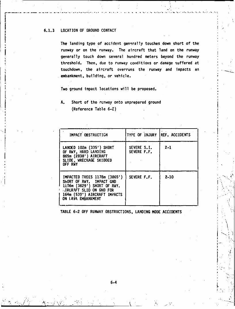
6.1.3 LOCATION OF GROUND CONTACT
The landing type of accident genorally touches down short of the
runway or on the runway. The aircraft that land on the runway
generally touch down several hundred meters beyond the runway
threshold. Then, due to runway conditions or damage suffered at
touchdown, the aircraft overruns the runway and impacts anembankment, building, or vehicle.
Two ground impact locations will be proposed.
A. Short of the runway onto unprepared ground
(Reference Table 6-2)
IMPACT OBSTRUCTIGN TYPE OF INJURY REF. ACCIDENTS
LANDED 102m (335') SHORT SEVERE S.I. 2-1OF RWY, HARD LANDING SEVERE F.F.865m (2838') AIRCRAFTSLIDE, WRECKAGE SKIDDEDOFF RWY
IMPACTED TREES 1178m (3865') SEVERE F.F. 2-10 >', .
ShORT OF RWY. IMPACT GNDi106m (3629') SHORT OF RWY..,IRCRAFT SLID ON GND FOR164m (539') AIRCRAFT IMPACTSON LAVA EMBANKMENT
TABLE 6-2 OFF RUNWAY OBSTRUCTIONS, LANDING MODE ACCIDENTS
6-4
9 1
-'\,• \V:

B. On the runway (Reference Table 6-3)
IMPACT OBSTRUCTION TYEOF INJURY REF. ACCIDENTS
TOUCHDOWN 60m (200') PAST SEVERE S.1. 2-0RWY THRESHOLD. SEVERE F.F*'
SKIDDED OFF RUNWAY.SLID ON BELLY FOR ABOUT 1O0m(300')..IMPACTED VEHICLE & ANDCONCRETE ABUTMENT.
IMPACT TAXIWAY 1219m (4000') SEVERE S.I. -2-13PAST RWY THRESHOLD.IMPACT TAIL FIRST.AIRCRAFT SLID 610m (2000')AND STOPPED.
TOUCHDOWN 732mn (2400') PAST MODERATE S.I. 2-8RWY THRESHOLD.OVERRUN RUNWAY FOR 34M (110')PLUNGED OVER A 12m (38 foot)EMBANKMENT
TABLE 6-3: ON RUNWAY, LANDING MODE ACCIDENTS
6-54
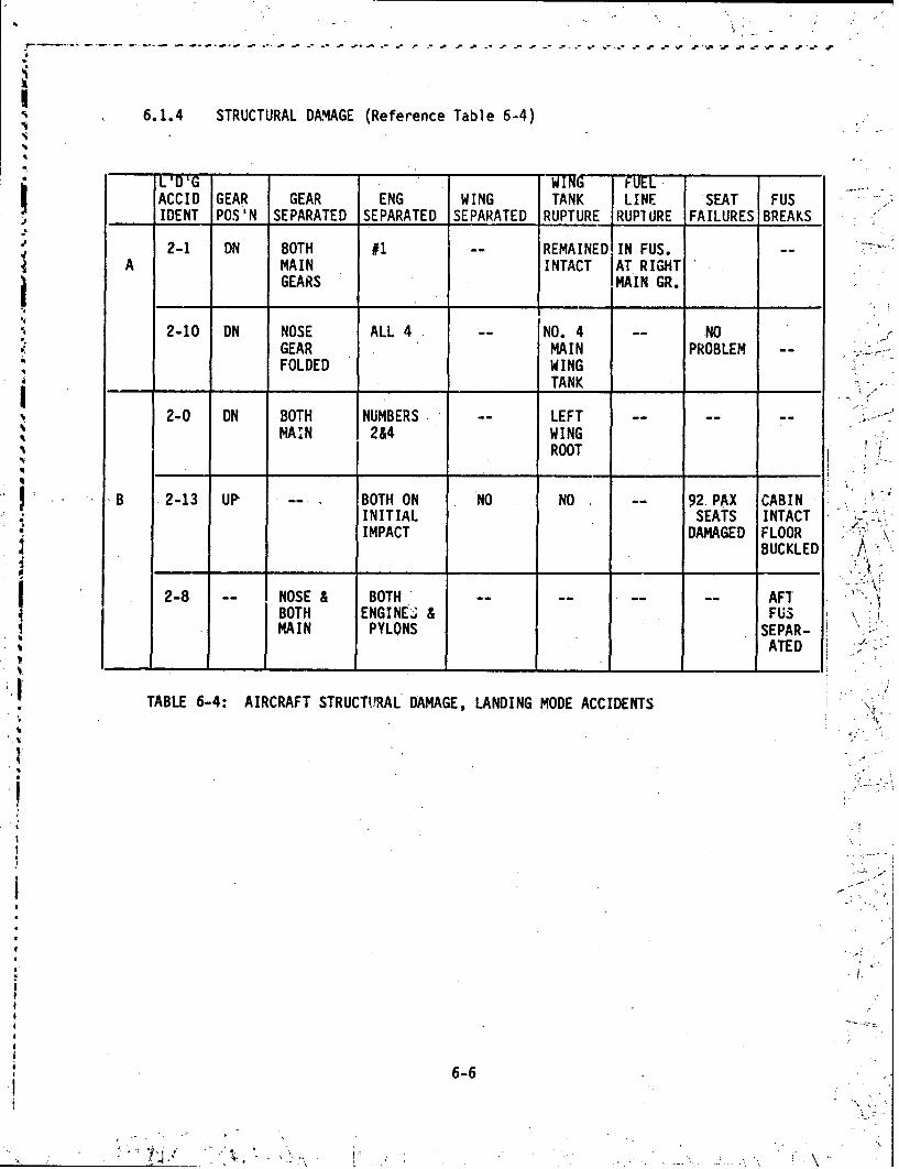
6.1.4 STRUCTURAL DAMAGE (Reference Table 6-4)
SL'DG .WING FUEL
ACCID GEAR GEAR ENG WING TANK LINE SEAT FUS* IDENT POS'N SEPARATED SEPARATED SEPARATED RUPTURE RUPIURE FAILURES BREAKS
2-1 DN BOTH #1 REMAINED IN FUS.A MAIN INTACT AT RIGHT
GEARS IMAIN GR.
".9
"2-10 DN NOSE ALL4 -- NO. 4 -- NOGEAR MAIN PROBLEM --
FOLDED WING- -- _ __ _ _TANK ,,__
2-0 DN BOTH NUMBERS LEFT -- -- "-MAIN 204 WING
ROOT
" "B 2-13 UP BOTH ON NO NO -- 92 PAX CABININITIAL SEATS INTACTIMPACT DAMAGED FLOOR
BUCKLED
2-8 NOSE & BOTH -- -- AFTBOTH ENGINEt.' & FUSAMAIN PYLONS SEPAR-ATED '"..
TABLE 6-4: AIRCRAFT STRUCTURAL DAMAGE, LANDING MODE ACCIDENTS
"6 -6
t.

6.1.5 S L LE t (i2,TI
The'se slide lengths will he associated with tne accidents
descrihed in Item 3 entitled "location of Ground 1 oact."
3(A) represents to c hdownns short of th-: runway and
3(B) represents touchiowns on the runway
A. Touchdon'n Short of the Runwvay
REFERENCE SlI I DEACC IDEN ET LF J;GTHI DESCR I PT I ON
2-1 83H N c obstacle impact(2838') at end of slide.
2-10 1(61lm Aircraft impacts on a lava(539') cmibankment at end of slide.
B. Touchdown On the Runway
REFERENCE SLIDE'ACCIPENT LEINGT(I DE SCRIPTION
2-0 100m Impacted vehicle and concrete(300') abutment at end of slide.
2-13 610;n N'o obstacle impact at end(2000') of slide.
2-3 Overran Plunged over embankment.Run iiay
6.1.6 SLIDE TIME
Thi - is the time span, starting from ground impact, to when the
aircraft come; to a stop. The slide time i's a function of the
average slide speed and the leng1th of the slide.
6-7
, I
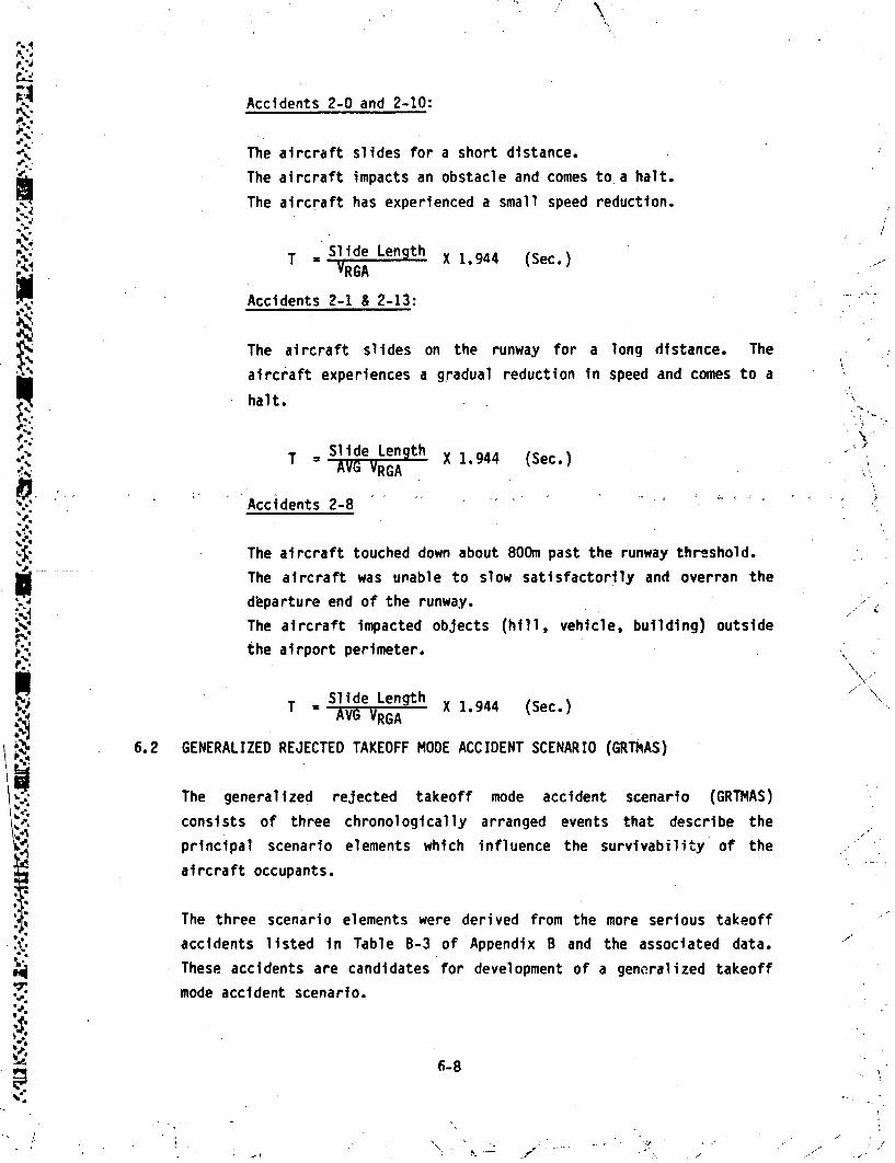
Accidents 2-0 and 2-10:
The aircraft slides for a short distance.
The aircraft impacts an obstacle and comes to a halt.
The aircraft has experienced a small speed reduction.
T =.ieel2.X 1.944 (Sec.)
Accidents 2-1 & 2-13:
The aircraft slides on the runway for a long distance. The
aircraft experiences a gradual reduction in speed and comes to a
halt.
T = ld egh X 1.944 (Sec.)AV RGA
Accidents 2-8
4.The aircraft touched down about 800m past the runway threshold.
The aircraft was unable to slow satisfactorily and overran the
dbparture end of the runway.
The aircraft impacted, objects (hill, vehicle, building) outside
*the airport perimeter.
* .~~ T = ~Slide Length X194 (e.T AVG VRGA X194 (e.
6.2 GENERALIZED REJECTED TAKEOFF MODE ACCIDENT SCENARIO (GRThAS)
The generalized rejected takeoff mode accident scenario (GRTMAS)
consists of three chronologically arranged events that describe the
principal scenario elements which influence the survivability of the
aircraft occupants.
The three scenario elements were derived from the more serious takeoff
These accidents are candidates for development of a generalized takeoff
mode accident scenario.
6-8

Meteorological Data
Air Temperature =1.2 C (34.20F)
Light Condition: Hours of Darkness
Rain/Fog: Fog
Ground Wind: 7.2 Kn (average)
Icing: Freezing Drizzle
j.6.2.1 TAKEOFF RUN
*1Flap position =12.50 (Table B-3)
Max. Airspeed relative to ground =VSTALL+.15 kn.
R
A .. Tire Failure (Ref. Accident 3-3)
The main landing gear wheels were locked from the start of thetakeoff roll. Soft, moist, clear ice covered the runwaysurface. By 1300m from the start of takeoff, all the left hand1 tires are flat.
By 2600m all the right hand tires are flat.
SRV is reached by 2800m¶The aircraft reaches the end of the runway at 3100m and does not
become ai rborne.
B. Collision on Runway (Ref. Accident 3-1)
The aircraft reached 145 kn at 1630m (5350') from the takeoff
* roll initiation point. The following pilot actions were taken:
power off
Thrust reversers activated
wheel brakes applied
spoiler extended
6-9

tN
Marked deceleration was felt at 1798m (5900'). The runway /
* length was 2377m (7800').i z
C. Bird Ingestion (Ref. Accident 3-7)
The aircraft reach 100 kn airspeed during takeoff roll.
A flock of birds rose in front of the aircraft. The birds
struck the aircraft. The pilot initiated the foohiilng zstion:
thrust levers moved to idle position
thrust reversal was initiated
heavy braking was applied
6.2.2 DECELERATION AND OVERRUN
A. Loig Runway Overrun (Ref. Accident 3-3)
At 206m (675') beyond the runway, the aircraft passed through a
* I wooden fence. K-"
At 305m (1002') the aircraft contacted the structure supporting
the ILS localizer facility. I
At 823m (2700'), the aircraft crossed a 3.7m (12') deep ditch. 7
At-1036m (3400'), the main portion came to a halt. ,
B. Short Runway Overrun (Ref. Accident 3-1) \
The aircraft overran the runway 68.6m (225') to the brow of a
hill. ' "
The aircraft became airborne momentarily.
6-10 'i °*
N-{-

I The aircraft contacted the ground 20.4m (67') further down the
embankment.
The main gear was sheared off and the nose wheel displaced* rea rwar.
The aircraft slid and came to -rest 128.3m (421') from the end of
the runway.
Li C. Halted on The Airport (Ref. Accident 3-7)
jThe aircraft was deceleratingNumber 3 engine disintegrated and caught fire.
j Several tires and wheels disintegrated.
The aircraft approached the end of the runway at 4Okn when it
was steered onto a taxiway.
The right main gear collapsed.
6.2.3 STRUCTURAL DAMAGE
A. Long Runway Overrun (Ref. Accident 3-3)
The wreckage came to rest in an upright position.
The fuselage sustained a circumferential fracture aft of thewing trailing edge.
The main landing gear assemblies were detached from the aircraft. -
The main landing gear tires were destroyed 'by friction milling
during the takoff run.
6- 11

.Y ~The left wing was damaged -following impact. with the ILS
structure.
NThe right wing tore loose at the ditch and a large quantity of
.s~d.fuel was released.
B. Short Runway Overrun .(Ref. Accident 3-3)
The main landing gear was sheared.
The nose wheel was displaced rearward and forced the cabin floor
upward .38m (15').
The fuselage upper structure was ruptured forward of the wing.
The right wing failed inboard of the No. 4 engine.
Engines Numbers 1 & 2 were partially separated from the wing.
SC. Halted on the Airport (Ref. Accident 3-7)
A. The right main landing gear collapsed.
The left and center main gears had separated.
* 6
The right wing fuel tanks were ruptured first in the No. 3 fuel
4 tank~at -about--T.-62m-(251) outboard of No. 3 engine.- --Th s--wasfollowed by penetration of the lower skin of the No. 2 fuel tankby parts of the No. 3 engine.
A
6-1

SECTION 7
ASSESSMENT OF ADVANCED MATERIALS
The demand for reduced life cycles costs for aircraft has created tremendous
pressures to use light or more efficient materials and adopt new manufacturing
processes. Ideally, these new materials and processes should not cause any
added concern about the impact tolerance of the aircraft.
7.1 Survey of Advanced Materials and Processes
The new materials to be considered can be grouped into three categories:
1. Aluminum Alloys
Metal Matrix Materials
3. Advanced Composites
The use of new fdbrication techniques may significantly affect the impact
tolerance of the aircraft. New processes to be considered are:
1. Bonding
2. Diffusion Bonded/Superplastic Formed (DB/SPF) Titanium
3. Large Castings
4. Filament Winding
5. Trapped Rubber
7.2 Aluminum AlloysI
There are several new aluminum alloys under active consideration. There
should be no significant difference in impact tolerance for any of
these. Aluminum alloys under consideration include the following:
1. 2224-T351
2. 2324-T391
7-1
- - -I

3. 7010-T76
4. 7049-T76, T73
5. 7150-T6
6. 7175-T736'•7. 7475-176, T76, T73
8. CT9O-T6, T7
9. CT91-T6, T7
10. Al-Li
7. 3 Metal Matrix Materials
T~vo metal matrix materials have emerged as candidates for structural
applications. These are Boron Caebide/Aluminum and Silicone Carbidecoated Boron/Aluminum. Both of these materials may be superior to
"aluminum in a crash scenario. However, no test data under impact
conditions exists. In iny event, these materials will likely find
application only in elevated temperature applications due to thefr high
"cost.
7.4 Advanced Compcsites
Advanced composite structure (primarily graphite/epoxy) Is both the most
promising new material application and the most controversial. Limited
data are available.
Even though advanced composite laminates will burn, they do not melt
appreciably. The burning of the graphite/epoxy composite would result In
pyrolysis of the resin; the graphite fibers would survive but matrix
cohesion and structural integrity would be degraded.
The use of graphite composites in commercial aircraft presents new
considerations particularly with regard to impact tolerance. Designs and
material modifications are now appearing to improve the durability and
toughness of the composite structure. It will he of immense interest to
7-2

determine whether these improvement for relatively low energy impact will
"* also show as improvement in the high energy impacts and crack propagation
associated with a typical impact scenario. At best, 'however, it is
difficult to envision a graphite (or Kevlar) reinforced organic matrix
equivalent to the metal structure.
It is probable that the use of advanced composites in commercial aircraft
may be avoided in some critical locations such as forward fuselage, main
landing gear, etc. where high energy impact might jeopardize passengerS~safety.
Advanced composite materials are now being used in structural
applications on a routine basis in military aircraft and will soon be
applied in many areas on large commercial transports. Graphite/epoxy is
Sthe current leading material to offer lightweight, strong, rigid
structure and, at the same time, offer' the potential for low cost
fabrication.
7.5 New Processes
Several new processes have shown promise for reducing the cost ofmanufacture. Some of these will affect the crashworthiness of the end
item and some will not.I1. Bonding - Bonded structure can provide significant crack stopping
which should be available at all impact energy levels.
2. Diffusion Bonded/Superplastic Formed Titanium - Superplastic
Formed/Diffusion Bonded titanium sandwich is very stable undercompression loading and exhibits exceptional resistance to damage
0 from high impact forces. The construction possesses good general
stability due to the ability to redistribute loads and dissipate
I energy. SPF/DB sandwich tends to crush rather than tear apart,
absorbs energy, and sustains high crushing loads. These attributes
.. provide increased impact tolerance when compared to conventionalskin-stringer construction normally used in forward fuselage
applications.
7-31

3. Large Castings - Large castings demonstrate efficiency by replacing
built up sheet structure. The latter have greater energy absorbing
capability. Consequently, the use of large castings may detract from
impact tolerance.
4. Filament Winding - This technique produces composite parts at lower
resin content than with autoclave curing. However, no tests havebeen found to date that would define either the resistance of a
filament wound part to high energy impact or the effect of resin
content.
5. Trapped Rubber - This process also tends to produce parts with lower
resin content but insufficient data is available to define impact
resistance with reduced resin content.
7.6 Test Recommendations for Advanced Composites
All 'current 'and probable future,matrixo resins generally,exhibit a low.
strain-to-failure characteristic behavior compared to metals. Extensiveimpact tolerance studies for metal aircraft structures have been
conducted (Ref. 22, 23 and 24) but an investigation of the impact
characteristics of composite airframe structures is needed and due to the
common strain-to-failure characteristic will be generally applicable to
whichever polymer matrix is used in the future.
The objectives of this impact investigation are the following:
1. Survey the literature to determine the existing data base on crash
impact behavior of composites.
2. Review current analytical methods used for the design of impact
toleranct airframe structures and assess their' suitability for
analysis of composite structure.
3. Develop the concept/problems that should be considered.
7-4
4. Outline the test needed to develop a design data base.
5. Consider the trade-off factors between concept selection, compatiblemanufacturing methods and various cost factors.
Analytical impact prediction methods should include structural
evaluation, material characterization, and failure analysis. The impact
environment needs to be defined from the literature in terms of expected
strain rates, and the time sequence of events. Characterization of
materials should be in terms of the energy absorption capabilities oflaminates and cores.
This characterization should include the 'post-bucking behavior of the
laminated composite structures. Failure analysis needs to include the
complex failure modes of laminated structures-for impact loading.
In addition, the analysis should he concerned with the structural aspects
of flammnability and the hazards associated with the thermal decompositionof polymeric composites during a post-impact fire. In particular, the
noxious gas and smoke evolution during the polymer thermal decomposition.1 should be related to human tolerance levels. Another issue affecting the
,.
response of a composite material structure in an impact environment isthat of service life degradation prior to the impact.
Concepts for evaluation should include as a minimum:
1. Maintain a protective shell around the occupied area.
2. Provide for post-impact emergency egress.
N 3. Provide energy absorbing structure to reduce impact loads on the
occupants.
7-5

4. Provide attachment structure to retain large loads and seats.
5. Eliminate strike hazards within the cabin.
a
6. Provide breakaway structure to prevent follow-on damage frcm engines
or landing gear.
7. New "crack stopper" or other constructions and new resin matrix
systems to minimize brittle failure modes.
There is almost a complete lack of data on the high energy impact
resistance of advanced materials. It is becoming a matter of some -
urgency that such data be developed for advanced composites as well as .
other advanced materials.I ,
Initial data: could first be obtained by analytical means from basic gmaterial properties applied to structural' design concepts. Subcomponent
specimens incorporating these design concepts should then be fabricatedand subjected to appropriate tests to provide a means of comparing rival
concepts, to ýprovide a means of confirming predictions and to accumulate
semi-scale impact test data.
Candidate materials for these semi-scale impact tests are
1. Aluminum for the program baselineU,
2. Graphite/Epoxy Composites : ..
Rigidite 5208/7300 for the composite baseline
CIBA #4/T300 (Reference NASA Rept. 165677)
BP907/T300 (Reference NASA Rept. 165677)
3. Thermoplastic Resin
C.' /:
PEEK resin with T300 graphite fiber
A new resin from a new NASA program
7-6 '
- II - . q

4. Two polyimide/graphite systems to be selected
5. Kevlar/Epoxy
6. Boron Aluminum
7. Graphite Aluminum
8. Large Aluminum Castings
The large favorable material/subcomponent specimens should demonstrate
the following properties:
1. The ability to aissipate large amounts of impact energy (i.e. exhibit
a large area under the force/deflection diagram).
2. Exhibit resistance to abrasion damage during sliding motion when thematerial is in contact with surfaces of concrete, asphalt and
unprepared ground variations of temperature and moisture conditions .4
which may be significant.
3. Exhibit low tendencies to produce heat and electric sparks whrile
sliding in contact with concrete, asphalt and unprepared ground.
There are at least four types cf tests needed to demonstrate the
adaptability of a material for impact applications. These tests aredesigned to simulate some element of an actual accident. The proposed .
test types are:
1. Head on Impact
The test is designed to represent a possible head on impact against a
wall or building.
The 'WEs specimen would be in the form of a cyclinder to represent4 , . .
three bays of a scaled down forward section of a fuselage. Thespecimens of the various materials must be of comparable strengths.
77C.

. "• ÷• A
The specimen would be subjected to an -xial load sufficient to cause
buckling. The load would be gradually increased to promote continued
buckling and colFapse. Observations of force versus deflection and
modes of failure would be made and recorded. The force/deflection
data for all specimens would be normalized to ultimate strength to
permit an equitable impact tolerance comparison to be made.
2. Vertical Drop
The purpose of this test is to demonstrate the energy absorption
capability of a material system for the possible high rate of descent
experienced in some accidents.
The portion of the fuselage structure that provides the cushioning
g for the excessive rate of descent situation is primarily below the
floor. Thus, the test specimen would have the form of three bays of
fuselage bounded above by the top of the fuselage and below ýby 'the'
fuselage lower outer skin.
l The specimen would be subjected to loads apDlied perpendicular to the
plane of the floor. The load would be gradually increased to promote
buckling and then increased to cause continued buckling and
progressive collapse.
The data to be recorded and the method of using the data is the same
as for Test No. 1.
3. Abrasion
During an accident sequence, a fuselage underbelly may be subjected
to abrasion. It is important that fuselage damage be kept to aminimum. Thus, a knowledge of the material resistance to abrasion is
necessary,
7-8
- - - -* -' _ _ :. . I

An initial evaluation of the c and idate raterial s could he
accomplished with flat plate specimens acted upon by a rotating ring
of abrasive material (concrete, asphalt or sand). The speed of the-.9--.disc, the mean distance of travel and the applied pressure wculd be
made to correspond to a typical impact scenario. The depth of the
abraded groove would reveal the desired material 'evaluation.
0 %;4. Sparking
An accident sequence may result in the aircraft sliding on its
belly. This can lead to sparking as the wreckage passes over a
concrete, asphalt or rocky surface which in turn may serve as an
ignition source for spilled fuel. Materials which avoid this
behavior are desirable.
Asetup and test procedure similar to the "Abrasion Test" (Test
No. 3) but with modifications could serve the purpose required here.The modifications consist of:
a) Placing a container of fuel and spraying some fuel mist in the
area where the sparks are expected.
b) Arranging the typical meteorological conditions. as described in
the generalized impact scenarios of Section 6, for the test
environment.
Failure to pass this test may not rule .out a comnposite material,
since the addition of a modest amount of a benign material such as
010 Dacron or Kevlar fiber could improve the properties of the basi
material.
N7-9

SECTION 8
EVALUATION OF THE
"AIRCRAFT CRASH SURVIVAL DESIGN GUIDE"
In a project begun in 1965 and continuing to the present, periodically updated
4 versions of the Crash Survival Design Guide have been published, the latest
being USARTL-TR-79-22A through 22E. These reports have as their objective the
presentation of the current state of the art in impact survival design for use
by aircraft design engineers. The Design Guide information has influenced the
establishment of certain Military Standards dealing with aircraft impact -.
tolerance (MIL-STD-1290AV).
As an Army project, the Design Guide naturally concentrates on helicopters and
light fixed-wing aircraft, but the design considerations covered are applicable
- "lin some degree to'large transport aircraft aswell. '.
Differences in the basis missions of combat versus civilian-transport aircraft
Sserve to distinguish impact environments and structural design ranges. The
combat aircraft is stronger and more manueverable. The civilian transport is
optimized for a very specific mission from which little deviation is expected
and is designed with a high sensitivity to payload/structure weight ratio and
to fuel consumption. Because the design strength of the civilian transport is
lower, it would experience more structural damage than the military airplane
in a crash at the same velocity. This is not to say, however, that occupant
survivability would be lower in the transport
The large transport fuselage is also a ifferent -type of structure, a
semimonocoque shell of low strength but hi h strength-to-weight ratio, and"with few areas of such concentrated streng h as a frame structure would
display.
riI
•' ~8-1
* • . , _ .c-. -- ..
,--I o .- y- -.-~-.1 \

Nevertheless, the Design Guide provides useful informiation for the transport
designer in understanding the general nature of the impact phenomenon, in
providing analysis and testing methods, and in setting out concepts and
j devices for improvement of impact tolerance of components.
The bulk of the evaluation for Volumes II and V inclusive is located in
Appendix E. The L.ialuation concerns itself primarily with structural subjects
p such as design criteria, design methods, design data and energy absorbing
concepts. Commnents on data 'about human tolerance to aircraft impact which is
'p contained in Volume III (Reference 3) is included in Section 9.
p 8.1 Conclusions
The Army Aircraft Crash Survival Design Guide is unique as a general aid
to structural design for impact tolerance. It is clear that overwhelming
emphasis is given to helicopters, although light, fixed-wing aircraft areI also covered.
14 The main value of the Guide to the transport category airplane designer
is in the illustration of methodology, and an important contribution is
the definition of impact conditions in terms of idealized but specific
acceleration vs time pulses. There is no Justification at this time for
the adoption of the quantitative properties of these pulses' for civilian
transports but it is essential that values for large transport impact
eventually be established before rational structural design requirements
can be evolved.
The degree of detail in treatments of various aspects of the structural
design problems is somewhat uneven, with Volume IV being notable for
comprehensiveness and sophisticat~gon in its treatment of design
considerations for impact tolerant seats.
The questions of dynamic vs static requirements in design analysis and
testing appear to be unsettled, but the development of static strength
requirements in terms of bounds on load-deformation curves, based on
j 8-2

extensive dynamic response studies, is a feas4ble approach. Theguide is also a 'handy source for particular design concepts and
devices, particularly for energy absorbing ustrokingm devices and forcertain material properties.
Review of the Design Guide suggests that much could be gained from a
project where the objective would be to set out a side-by-sidecomparison of the current requirements for civilian and military.'
aircaftand in light of this to review the basis for differences,
an osuggest testing and other research programs which might updatetecurrent requirements.
It is clear that a conmmercial transport equivalent to the U.S. Army
'Aircraft Crash Survival Design Guide would do much to centralize the
location of the large quantities of data now in existence and expand
its use in aircraft design practice.
8-3

SECTION 9
HUMAN TOLERANCE TO IMPACT
Many indices have been proposed for the purpose of giving some measure of the
liklihood of occupant injury during an impact sequence. Several of the more
prominent indices are discussed in Appendix F.
These indices include the Dynamic Response Index (DRI) and other spinal injury
models, the Gadd Severity Index and the related Head Injury- Criterion (HIC) of
*Federal Motor Vehicle Safety Standard 208. A brief discussion is given of leg
injury criteria, of indices for "off axis" accelerations, of the shock
spectrum approach, and of flailing-distance and volume-reduction indices.
9.1 Conclusions
A number of injury criteria, both local and whole-body, have been
*proposed, although the experimental data base from which they have been
drawn is extensive, there does not appear to be any comprehensive set of
criteria which a design engineer could use with confidence in transportaircraft impact tolerance application. Criteria applicable to Air Force
ejection seat design should not be carried over to the transportpassenger who exhibits a wide 'range in age, size, weight, -physical
condition and degree of restraint. A careful study which results in adefinitive set of injury criteria for transport impact, application,
would, although expensive, be an important contribution to the state of
the art, without which a real evaluation of impact tolerance would be
impossible.
9-1 [-

SECTION 10
MERIT FUNCTIONS
The merit of a concept is a function of parameters that are intimate 'wi'th the
design objective of the concept. For ea&I design or conceptual alternative,these parameters take on a specific set of magnitudes. These parameters canbe combined into a single number which expresses the merit of the design. Thebest design among competing alternatives produces the largest merit value.The parameters fall into three categories: cost, effectiveness, and societal
concern.
The cost element can be represented in one of two ways: acquisition cost. or
direct operating cost. From the viewpoint of airline management, direct
operating cost is the most desirable measure, since it includes the'acqui-sition, cost ofA each incremental change to, the airplane. From themanufacturer's point of view he must know, with some precision, the magnitudeof costs involved with proposed modifications. In any event, a baseline mustbe identified and its cost established so as to derive the effect of~incremental changes.
Directing operating costs are derived by use of the Douglas AdvancedEngineering Method, which represents a continuum of updating of the 1967 ATA
Method. The major modifications made for updating include 1980 price levels,current operating practices, profiles and performance, and system attributes.The basic constituents of the direct operating cost (DOC) of aircraft are ---
flight crew, cabin crew, airframe depreciation, engine depreciation,insurance, landing fees, airframe maintenance, engine maintenance, and fuelcosts. A typical DOC schedule represents a single airplane with arepresentative type of operation.
Acquisition costs include the price of the aircraft, with estimates of proposedIlkcandidates for changes derived on a discrete basis. This means that proposed
modifications to the baseline, such as changes in structures configurations,
10-1

have been reviewed as separate issues for each configuration. The development
program, which includes also the type certification, has been summarizea over
a given quantity designated as a breakeven point. Cost elements used toI
derive a price are shown below:
o Design Engineering o Sustaining Engineering
o Fabrication o Sustaining Tooling
o Assembly o Manufacturing Development e
"o Inspection o Planning
o Tooling o Flight Test
o Raw Materials and Purchased Parts o Laboratories
o Instruments and Special Equipment o Propulsion
So Product Support o Miscellaneous
The nature of the study dictates very clearly that case examples have to be
structured hypothetically, since quantities of airplanes must be.assumed for
amortization purposes and breakeven determinations. Other factors include use
of new or existing aircraft, class of airplane, .etc.
It is premature at this point to suggest structural safety concepts because areliable analytical method is unavailable to perform dependable merit function -.
studies. The evaluation of advanced composites through impact analysis and
test described in Section 7 and the experience and data gained in the
recommended analysis and component test effort of Sections 11 and 12 should
help reveal structural concepts capable of improving passenger survivability.
t
102 •

SECTION 11.0
ANALYTICAL METHODS
It is contemplated in the future that. analysis methods will be used in
X, ascertaining the dynamic behavior of an aircraft under impact conditions. Two
accomplishments are necessary for this to occur: (1) accepted impact
scenarios and (2) adequate analytic prediction procedures. This latter
* category is of concern in this section.
11.1 Analytical Requirements
Impact dynamic analysis methods for large transport aircraft are
envisioned as a set of programs of differing complexity which serve avariety of purposes. These include (1) performing preliminary designs,
(2) improving impact tolerant designs, (3) simulating accidents, (4)
aiding in establishing impact criteria, (5) analyzing final designs, (6)
providing properties* for simpler programs and (7) verifying suitability
of simpler procedures.
The. intended purpose essentially dictates the requirements of the impact
analysis method. For performing preliminary designs and parameter
studies for impact tolerance improvements, it would be desirable to use a
reasonably simplistic program which is relatively fast and inexpensive to
run. Its. accuracy need not be so stringent as to require a detailed
reproduction of the actual response history, but it should give, for
instance, a reasonable estimiate of the peak accelerations to which an*occupant is exposed. As an example, this type of program could begin
with a defined set of acceleration impulses at the base of an occupant's
seat.
Representative impulses for the indicated simple method can come from
test data and/or analytical simulations of the complete aircraft using a
more complex program, most likely of the hybrid type. This form of
program incorporates a coarse model of the aircraft structure, preferablycontaining less than 300 degrees-of-freedom. The impulses to

be defined by this program are of sufficiently short duration to permit
CPU times of the order of 10000 times real time. The hybrid program
should also indicate the potential for wing fuel tank rupture, fuselagerupture, penetration of large masses into the fuselage and excessive
volume change of the occuppnt's cabin. The hybrid program must be able
to simulate both landing and ground run impact scenarios with starting
routines appropriate to these conditions. Subsequent to the start, it
ashould be able to handle nonlinear- effects produced from largedeflections and material inelasticity and permit the airplane to
adequately interact with hard and soft surfaces of varying profile.
Within the hybrid category, but of simpler form, could be included a
full airplane program which consists of flexible modes and nonlinearelements for the under part of the fuselage. and landing gears. This
program would be used for less severe impacts dominated by verticalimpact. A program classified as simple, should contain less than 50
degrees of freedom for the structural model, but may be merged withAsimplified forms of occupant models. The execution CPU time should be
less than 1000 times real time.
In order to operate the hyb' 'd and simpler type programs, the nonlinear
properties for any highly loaded structural element must be developed
from test or an advanced analys;is prom!' 're of the finite element type.*In order to serve this *jurpc3e, the finite element procedure must be
able to handle large deflectitas ana inelastic material behavior. Italso should have the capacity to work with structural models containing
in the order of 1000 degrees of freedom.- A- finite element program canbe used to determine whether significant differences exist between
Zj static and dynamic properties. The CPU time for establishing dynamic
properties can be as much as 100,000 times real time due to the short
duration of real time simulation needed for this purpose.
V-4
11-

11.2 Review of Existing Analysis Programs
Computer programs concerned with impact dynamic responses presently
exist which have extensive histories of development. Three of these
programs were given a limited review in the course of the study effort;
ne ly, KRASH, DYCAST and SOMLA. The total airplane impact dynamics
simulation program KRASH is well documented both technically and for
usage (see References 13 and 14). The occupant-seat dyn,-ic impact
program SOMLA is similarly well documented (see References i, and 12).
The attributes of the finite element impact dynamics program MYCAST were
mainly discerned from published papers (see, for example, Reference/ "."
10).
None of the above computer programs were run in the course of the
review. Because of this, no comment can be made concerning the ability
of these programs to predict with reasonable accuracy the impact dynamic
responses of large, transports.,, However,: the literature (e.g., Reference-
10) indicates that the KRASH and DYCAST programs can provide
satisfactory response predictions for less complex airframeconfigurations and simple impact scenarios. Reasonable correlation has
also been achieved between controlled experimental results and SOMLA
program predictions when simple seat configurations are used.
(Reference 9)
Since no work was done with these impact scenario computer programs,
only subjective remarks can be made concerning the implementation of the
considered programs. Adequate user documentation is a necessity for
implementation. Both the KRASH and SOMLA programs are presently
satisfactory in this respect (see previously cited references). SOMLA'
limited scope along with its standardized occupant and seat models makE-
the set-up of the program relatively easy. The KRASH program utilizes a
simplified airframe model composed of an open grid of beams. Although
providing a documented explanation of the way to set the properties for
the model's elements, the beginning user would have great difficulty in
first defining the model for a large transport and then establishing the
numerical properties of its elements. Extensive trials with the program
by a devoted operator would be needed to surmount this difficulty.
11-3
-~ -A-'.

Defining the model for the structure of a large transport is the most
difficult step in implementing a finite element computer program such as
DYCAST. The size and complexity of the large transport structure
*imposes considerable limitations on the 'modeling detail that can beused. Due to its involved nature, it does not appear that a finiteelement approach can. be used for a complete large transport aircraft.
Instead, the finite element procedures will most likely be limited to
localized portions of the structure either for establishing properties
or refining results obtained from more gross analyses.
Of the reviewed programs, only KRASH is potentially suitable for large
transport airplane impact scenario simulations. The technical approach
to the KRASH program satisfies many of the requirements mentioned in the
previous section.- Its limitations *in dynamic degrees of freedom seemstoo restrictive for large transports. The running time of the program
is satisfactory for scenarios in which the primary responses occurwithini 0.2 seconds after initiation of the impact sequence., The mostdifficult. matter to discern is the modeling detail needed for large
transport fuselages. There is no clear methodology for laying out the
beam grid for the fuselage and then rsetting the properties for thebeams. Given the grid, it appears that the properties of the beams areprimarily set to approximate the stiffness characteristics of theoriginal structure. It is not evident whether these same properties are
satisfactory for obtaining an adequate internal stress state for failuredetermination. Large displacements are handled well in KRASH through
the Eulerian formulation. The manner of accounting for inelastic -
---effects-- by means of the KR factors appears -to-be- reasonable and fitswell into the hybrid concept of the KRASH program. Obtaining the data
for these factors, however, may be a formidable task.
In KRASH, the impact sequence can only begin with the airplane in alanding attitude at touchdown. This should be generalized to permit theairplane to also assume a takeoff attitude at the start. Theevolutionary nature of the impact responses precludes the considerationof arbitrary start ing points during the impact sequence. The airplaneduring an impact sequence can be in contact with either hard or yielding
11-4

surfaces. KRASH contains a simple soil yielding model which in many
respects fits well into the concept of the total program. It isn't
apparent, however, that the plowing force should be prescribed
independently of the yielding. The terrain over which the airplane
operates in the KRASH program is defined by a linear varying or ramp
* type profile. Arbitrary profiles representing features as ditches orembankments are not covered. This situation should be relatively easy
to remedy in the program.
In contrast to the corresponding weakness in KRASH, the strong point of
the DYCAST program is the ability to follow the structure's internal
stress behavior in sufficient detail for the assessment of the failure
potential of the structure. In this regard, the seat finite element
formulations in SOMLA needs improvement. Apart from this aspect, SOMLA
handles the combination occupant-seat analysis quite well providing,,
detailed graphics of the occupant's motions during the simulated impactý
Icondition. It ,would be desirable to extend SOMLA's analysis capability.* to cover coupled multi-occupant, multi-seat responses.
U / ,
* Ii
II
tt
11-5
/r- , .\ .I
/ ..'*\ a "• .

11..3 Analysis Reco5ýmendations
Experience with the predictive accuracy of analytical programs is most
preferably gained by making compa~risons of calculated results with thoseIIfrom controlled experiments. The latter, however, are sparse for
helicopters and general aviation airplanes and essentially nonexistent
1for large transports. If the more elaborate impact dynamic programs
such as DYCAST and KRASH can predict responses reasonably well for the
former categories of air vehicles, then the predictions from these
programs for large transports must serve as a reference until suitable
experimental information can be obtained.
P, It is important that development continue on these advanced programs,_j particularly in the area of large transport structure modeling. The
predictive performances should be further checked by comparisons between
each other on actual transport designs, as well as on contrived
structural models. Checking should also be made against experimental2. data obtained from relatively inexpensive impact tests of structural
components. Modeling approaches for seats and occupants should be
included in the structural modeling investigations. For organizationswhich may use the advanced programs but have not been participants in
their development, workshops should be set-up to gain familiarity with
these programs.
A significant effort should be devoted to the formulation of simplified
analysis approaches which serve preliminary *design and parametric
variation study purposes. One concept to consider is the application of
shaped acceleration pulses at the base of the occupant's seat. For thisapproach the primary activity would be in establishing the properties ofa set of pulses. A second concept could involve modeling most of the
airplane by means of flexible mode shapes. This model would use
nonlinear elements below the fuselage floor and would be able to account
for mild impacts. For preliminary structural dasign, -it should bee.-,plored whether the results of this last model could be empirically
scaled to higher impact conditions. Irrespective of the concept, theadvanced analysis programs would be used to generate the data nocessary
for the development and verification of the simpler programs.
11-6

SECT1uN 12
TEST METHODS
An adequate test program is vital to assist in the search for and thedeveloping of safety improvements.
Testing for impact tolerance improvement, from the point of view of structural
response of a transport category airplane in an impact situation should be
directed to achieving one or more of the following six objectives.
o Determining Survivability Boundaries N
This is the empirical determination of the parameter ranges within which
an impact is survivable.
o Characterizing Impact Conditions
The determination of external forces on the airplane to be expected at
various impact speeds, angles, gross weights, terrain types, etc.
o Identifying Structural Failure Modes
It is of extreme importance to know the manner in which structural.
subsystems will fail during the impact: plastic deformation, fracture,
buckling, etc.; including the sequence of failures.
o Determining Structural Properties
Besides known material properties (elastic modulus, stress-strain
diagrams, etc.) it is of interest to have the ability to model a complexstructure by a simple one such as a spring. Force-deflection
characteristics of the complex structure are needed under static and
dynamic conditions.
12-1

o Evaluating Design Criteria
Dynamic tests of full scale systems and subsystems are needed in order to
judge whether current static design criteria are reasonable and adequate.
Critical failure modes become apparent in a sequence of carefully
observed tests. Then the designer can direct his attention to specificmodes.
iThere are five types of tests reviewed in this section. Of these, whichinclude total airplane, scale models, terrain, structural subsystems and
simple structures, structural subsystems testing is the experimental approach
which will provide the most useful information for enhancing impact tolerance.
Distinct areas such as landing gear, fuselage and seits should be highlighted.
Considerable analysis and test planning will be necessary to ensure that tests
* will be run at maximum effectiveness. Static testing alone would be of
limited value, and the parallel performance of static and dynamic tests of
equivalent specimens would improve our understanding of dynamic failure mpodes
and would enhance the capability of analytical prediction methods.
12.1 Review of Past Test Programs
A review of reports listed as References 15, 16, 17, 18, 19, 20, and 21
was carried out. References 15 and 16 report on the impact tests
performed with full scale propeller transport aircraft that bear a close
representation to the majority of the aircraft types being studied here.The material of References 17, 18, 19, 20 and 21 are of less direct
interest since tiey apply to general aviation aircraft and scale testing.
Impact tests of full-scale aircraft have been performed in three areas.Helicopters have been drop tested to determine undercarriage impact
response and crew G-loading. NASA has performed a large number of
12-2
J-14
______ NA

* -s tS S ~ ~ S . ' - .' .S' f bf! . -. . '. * / S* . . -.,
I..
"pendulum swing drops with single and twin engined light airplanes. The"only full scale impact tests of large transport aircraft were sponsored
by the FAA and reported in 1965. There were two airplanes tested: a
Douglas DC-7 (Ref. 15) and a Lockheed Constellation model 1649 (Ref. 16).
Each test was run on the ground. The aircraft was guided into a series
of barriers with a monorail nose landing gear guidance system. Instrumen-tation consisted of accelerometers, anthropomorphic dummies and motion
picture cameras. The principal achievements of the tests were the
verification of a method of producing a realistic impact environment and
the production of useful records of acceleration vs time at various
points on the aircraft and of records of subsystem failure modes. A
number of restraint system experiments showed that occupant restraint
"systems enhance safety.
A review of the highlights of the impact test of a Douglas DC-I aircraft
-(reported in Reference 16) Is presented in Appendix C.... .
12.2 Recommendations for Future Tests /
All of the conceivable testing in this area will be of one of the
following types:
o total airplane
/ • o scale model
o terrain
o structural subsystems
o simple structuresb
Each of these types of tests has its own set of implications for cost,
achievable objectives, and methodology.
172-
j12-3 - 2
• - ., - - -.
* 12.2.1 Total Airplane Testing
For our purposes, the DC-7 and Constellation tests methodologycould be utilized and updated with modern equipment, particularly
in the application of telemetry techniques. Much of what would
be learned, howeve r, would be of a merely qualitative nature, and
it is not clear that such information is not already available in
the earlier reports and in actual data records. Structural
dynamic information generated in such a test would be most useful
for characterizing impact conditions, e.g.j in learning of the
duration and character of the accelerations experienced; and in
substructural testing, e.g., correlati~ng occupant/seat accelera-
tions with floor accelerations. Some correlation of fuselage
crushing with floor loading would I'be attempted, but the proba--__bility of success of such an experiment is doubtful because of
the high degree of uncertainty inherent in measuring deformations.
In light of the expenses which would be involved in such a test
it is unlikely that conducting one! for structural dynamic testing
N purposes alone would be cost-effective.
12.2.2 Scale Model Testing
The utility of scale models in imp~ct testing is small because ofthe uncertainty in scaling laws for' structures undergoing grcis
deformation under impact conditions. This uncertainty existsbecause- the physics of dynamic failure of materials is not wellI
understood. Also a realistic model of a monocoque airplane
4 structure would require such extreme detail in representation
that the model would probably be more expensive than the full*scale version. Accordingly, scale model testing generally should
not be considered unless full scale tests are absolutely ruledout by lack of test facilities. This, however, does not seem to
be the case.
12-4

12.1.3 Terrain Testing
An airplane impact involves deformation of both structure and
ground, often with a noticeable plowing effect. Modeling the
ground response by a spring and by a sliding friction coefficient
'4 appear to be necessary where analysis techniques of simulation
are used, as in the Lockheed KRASH computer program.Determination of ground friction can be achieved through drag
tests using a weighted rigid model. Experiments of the plowingI- ~effect cannot be devised without first developing scaling laws, Ii
probably based on momentum and fluid mechanics models.
I12.2.4 Structural Subsystems
Static and dynamic testing of aircraft structural subsystems
provides the greatest promise for improving impact tolerance.~ .The7 following -are the most promising substructures--,
landing gears
seats
fuselage sections
With landing gears the important questions involve breakaway
loads and post-breakaway penetration of fuselage or wing,
particularly 'with regard to fuel tank rupture. It is probable
Ijthat. landing gear design for breakaway will enhance overallsurvivabilttyin. a accident; that is, landing gears-should not be
as strong as possible: and high impact loads are probably better
distributed over the fuselage underbelly.
Another factor to be considered is that the reliability of
computer program analysis methods are still unproved as well as
lengthy and expensive Thus, for the purpose of providing a
basis for developing a simplified method of analysis (as
suggested in Sections 11.1 and 11.3) along with
12-5

improved accuracy, a test program has been outlined below and inAppendix D which is capable of providing basic impact data such as
1) Component load versus deflection measurements. (Acquiring
load data for these tests may require a calibrated platform
to receive the impact of the specimen in motion.)
2) Component failure modes (fuselage, wing, landing gear).
3) Structural member failure modes (stringer, ribs, frames).
4) Accelerometer load pulse plots.
The test program consists of three basic types of tests.
1) Landing gear and wing structure
0 Static testoDrop test onto unprepared ground
oDrop test onto a cement runway
2) Fuselage underbelly
0 Static test
o Drop test on underbelly on unprepared groundo Drop test on underbelly on concrete runway
o Fuselage break drop testo Fuselage slide on unprepared ground
o Fuselage slide of a concrete runway
o Fuselage head on impact against a large tree or building.
3) Seat and support structure
o Static test
o Drop testo Mounted on sled in motion
12-6

Aircraft component tests were preferred due to the excessive
expense of full scale complete aircraft tests. In order to
ot~ain an indication of the range of desired data, aircraft
components for test should be obtained from small, medium and
large aircraft from salvage sources. Obviously, initial testing
would be done with components fabricated from state of the art
metal materials and methods. Future tests involving composite
aircraft components would probably require components especially
fabricated for this purpose due to unavailability of salvage
specimens.
The initial tests would serve as data gathering exercises,
whereas later tests could serve as analysis verification efforts
as well.
The basic purpose for this program is ~to, improve. passenger.
survivability. These tests may also serve to reveal the need andprovide methods to accomplish design improvements.
The conditions for these tests will be derived from the
recommended critical generalized impact scenarios in Section 6.
12.2.4.1 Landing gear impact tests of the following types may be performed.
(A) I'i.ighted wing section with
gea,, impact against a bumper.
Record possible penetration of wing.
Measured loads at gear breakaway.
The tests should be performed WIN
dynamically (at typical landing
and slow-flight speeds) and VAWV"statically" (very slowly). ,.-
Impact at various angles.04A
12-7

(B) Weighted fuselage section with
gear impact against a bumper.
Record load-deflection history.
Evaluate penetration of fuselage.
Determine test strength of damaged fuselage.
(C) Drop test onto an incline plane
(Reference Appendix 0, Test 1.1.0, Figure D-1)
12.2.4.2 Fuselage drop tests will provide information about the modes
of crushing of underbelly structure, and the force-deflection
characteristics in the collapse. Static tests provide force-
deflection chartacteristics. Probably a section containing a
minimum of three bays will be needed in order to account for
longitudinal buckling. (Reference Appendix D, Test 1.2.0,Figure D-2)
Fuselage drop tests will provide accelerations vs time at
various floor points, at seats and at anthropomorphicdummies. (Reference Appendix 0, Test 1.2.0, Figure D-3)
Shearing of the fuselage is a critical failure mode affect ng Y'
survivability. Drop tests will determine the net impul e
required to bring about a fuselage break. (Referen eAppendix D, Test 1.2.0, Figure D-4)
1I12-8

12.2.4.3 Seat testing should be performed both statically and
dynamically. Results will permit evaluation of current*1static load design criteria and determine occupant Gloading at the point of seat failure. Seat testsIshould cover longitudinal, lateral and vertical
4accelerations. Sled tests, or, if feasible, drop testswould be performed. Multiple seat specimens should be
used, as the strength and failure modes of multiple
seat packages may differ considerably from those for
single seats. (Reference Appendix 0, Test 1.3.0)
Comparison with existing analytical techniques, such as
the SOMLA code with seat capability, would be made.
12.2.5 Simple structural tests (i.e. tests on subcomponents such as
b eams or columns) are not recommnended since they do not
-'provideý useful' "information on the ' impact behavior of'
airplanes and do not suffice to validate a computer program.
In the latter case, even if accurate predictions were
obtained there would be no assurance that the applied
methodology would perform satisfactorily for more complex
conditions.
12-9

APPENDIX A
[ ACCIDENT DATA BASE
This appendix sunmmarizes the entire accident data base used in this study.
KiThe aircraft of the data base accidents are principally domestic aircraft
certified to FAR Part 25 in the service of domestic and foreign airlines. The
data base consists only of accidents judged to be impact survivable (i.e., in
which all occupants did not receive fatal injuries as a result of impact
forces imposed during the impact sequence). Table 4-1 gives an indication of
the degree of documentation available with each accident record.
The accident data is presented in three tables according to the flight mode of
the aircraft prior to the crash. These tables are:
I Table A-i: Approach Accidents
Table A-2: Landing Accidents
Table A-3: Rejected Takeoff Accidents
A-i

co -6 44-l
HE 1.81-%
40 cMOO -
~~~ "tI~ '
39 Uz.
9% V% -W .9
I~~ I
F0-j I L I I I I 4I IL I I
IL,
A-2

IIA
C44
1,.1
th -S .- 02 -Z :4 : 4 w zz
-. - I=..Qw54"41
I'in
C4
0 4
La P. r- .
-4 -a 04 A1ao NNoa
I."
% .. I - - . . . . . . .: . . . . . . .. .
A-3 ,

'3 JA iti
I Iz;.
-1 '1J 4 -- q.
-. -. z0
.3 I.
w 5'
A ' is 42 gx
-4 C4 0
-A-4

lo , I 4
I~~a~3 *0 Z Z0- ~ W 0
S.. * 0 L 0n 4t .'
5U .0 v -YL) 0 4 f~.,
4-1)
6, -. > 7
We 44 13 X
I V% I a, I I S I I
- 1. 0 N 0 0 0 0 0
cmI M% 0 '
on In
&J C. a a. a. IL IL C.a. a a
IL CL
Co..
4n >- r .f i - L-
Ir Nw c N
a-~~ m- a-:-I . '
4~r %0 ' 0 I 0 '0r. -a 4 N 4
04~~C~ N .4r v44 '0 4 N4 N 4 3
-0 -4 .4 -v.0
N C-1 N N IN N ..
A- 5

K tI . /
Ell 'a -8--
MEM a. 0"
IDI
/ .,,! •l x..,R,,, al/ I . -, ,t i . .II ,- t <
/ g ,,t tl -• ll, •lt I il . ,.+
44
. ,. . f + .0 't .r f.. o
a.. maI. ~ I I l
.36.
,- -
41
s** I - - maI a
4•,, , , , ,m.
a- ,a - - °£I l
- 1- * ='
A-6
4% a .4 % a- a- % 4% a- * a C
i . "/ -. / . -/ \
S. , y /

-z a a uIFI,
12-
-6 -' " - . - f.I -
RZ if* a" -ia. .g- AS.I
aa 21
Ps-f
A-7

ii • /, , , , , .. '7. - " '' .
-Jl
N 5.
I\9C
"" i" M 0 .2
Sc-
. i A t5 5.,.. 11 ais ° "•~~~~~ ,IZ II -a•'"•.¢ .
3 51
: 2 ..
.. 4 2 i v .0 1 1 ',C r
4~. p*". C %D
U *~ 5 w -A-8

i..
lei I C- a " • - ' " I"• •7 ':...
8 • -'. •s s .
S ! I I L CL L L I L L I 4L L M M M M w
44'
am I~-
""0 hI .SI .I *'
-A-9
S 0 I UU U U U I I U

I APPENDIX B
-~SCENARIO CANDIDATES ACCIPFNT CHARACTERISTICS
This appendix contains listings of accident data from the well documented
jaccidents which are listed in Table 4-1. The data is presented in threetables:
Table B-i: Approach Accidents - Characteristics and Associated Injuries
Table B-2: Landing Accidents - Characteristics and Associated Injuries
Table B-3: Takeoff Accidents - Characteristics and Associated Inl~uries
In these tables, the accident characteristics are grouped as indicated in
Table 5-1. A brief analysis of these-tables is given ir. Section 5 of this
report.
B-i

j~b XP.q CN O. N b. CAN.
-J --------N, ?. N 9
5 I.
.- ko .. t V4
in0 0 a 0 0 p 0 0
1-''A
I.on a
a -D -
.7-~~ 0I- C) 0;7
17 00000 00
440 1 0
B-2if

.4 4 0 d) 44) 4). 64 23 0 0 4
c 4) 0( 4 -4) :3 413 U
4,! 47 .In'4 ~ ~ ~ ~ ~ ~ ' 40v A .. 44.
JSV
61 N4 WN Ch. S41, m
04.4 -J .J ~ ~ c .rz O' (14ý- L's S *'
u, ) 4, 1- 4 'C4:U1 0 0 5(
44 A
, r- ,~ , Iý r. I
Si 54. i -i 9x. 0
14 C,
Vi 00 000'0
LB-3
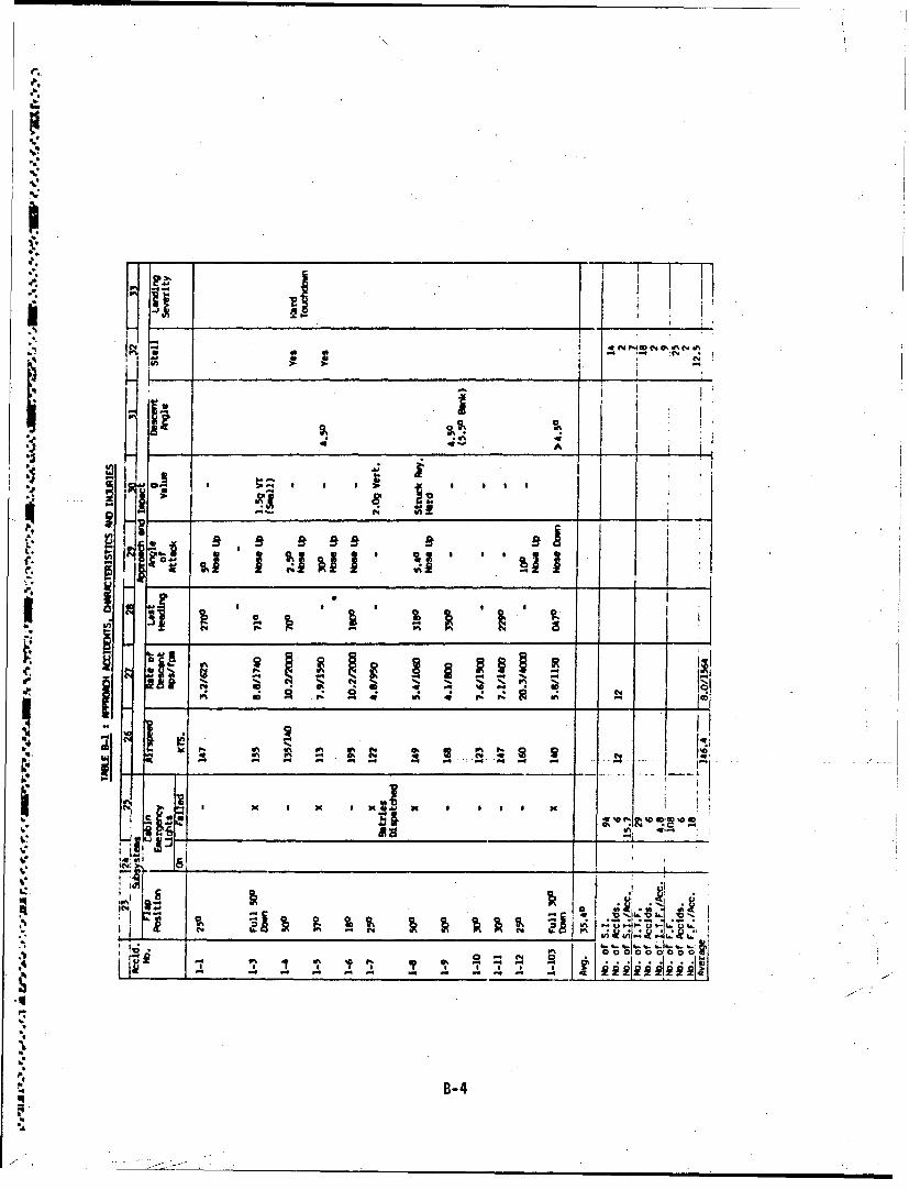
~h44
Z ,,
%. 4 ý. t ..
L i -_ _ _ _ _ _ _ _ _ _ _
W,,
~i , , ,
oJ ' ' e
1 4 4 .. .- ..
4B-4
z-.

40
JP
d I.u
_ _ _ _ __'4_ _ _ _ _ _ _ _ _
a 49 b" -r V- .~ ~ -9U Sol
x. -X 1 xxo
PN 04b. .
Ll I
if- tt~B-

- -
'o '9A
-9 to'it
f3__ ___ __
-B-

LeV
NZ.
rt rcU;
V% C4 A
404
c .60
28 a5 C j 1.4
jj
I B-7
- - I

'141a C
__ _ _ _ _ _ _ __ _ _ _ _ _ _ __ _ _ _ _ _ _ It c
V -iww0
p %.
- 0
CN
LO zo
"IB-

%. 7
59-
ioi
z4 r
10 0 XX 0 0
to 0%4
B-9~

A 1!
I~~ .... .
S. 'A
mai
Ix .
S*-"
ino
a. -•...
ti
B-1
4.-.,.!
€ .• . *4, .6

al i-l
•b
B-11 '

.4N N
~I a
rm .1
.rCB 12-

Ra
'Sl~
bw
JI
iA
44 4_ Z_ el
B
.- ,o. __ _ _ _ - - -.4
,* j•
SB-13

ID~
AM vIco~ > 0V)U
I0 -. elpW
11
NN
A -A
WIE
ZBu1

! .
ION
ni nt
-. ,
4 B- 15
P-I
Dli ul\
C /'\"
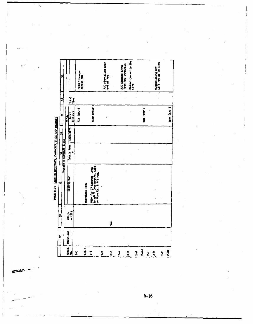
ScS
B-I1

to~
H ii..I
A.
-
" ° I••-
17
IF *•;
w.•
-II
~jii
-: - .
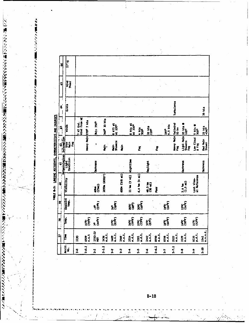
p
F
.4
6
.4.4.4
4'I.4 ___________________________
4**Jk
*1'.4.44.4S
a.4I IA
U, _______________________w -
a- .4 a '� aP4 4. U
In.- *4 a4. .Xe4. a 4.0J..4 * I- .�Q. �F � .;� b g*6 -- --
c c- - -
� £ a a..-.4 ,, � lb lb
a�a 8'U
d U 4. a
-a I! a
I A., - -* -q -
�.4. - d a a.
U � - jIA - jj --5;* I ). �
*.4 I
a. - - a
4.4., 1
4
9 4 1 � 4.M 4. 4. 4. :�::�.4. - 0.4-41 -S �a �S NS -. -. 55 SOS l�S t.4S 00. (.5
-4 -4 .4
.4%. I� i� �
I., � 47(44 (44 (44 (44
* .4
p
* I
�.>11'I.
* B-lB4.4
� t*.t � .4.�. � -- - -.
N-, . / - r

o m
Zi.I
.'
iS
* LU
CL;0
-. r . w
ini
C4 A
B- 19
\ , . . ..

x x - - C4I
Ix 09 0
-~~~ Iw - - * U1
.59'
oz
.5 A-JJI ~i3 1
,0COC 0 00 C a C 0 0 0 0
* ca ~ - a a a acae a a.
I 4
F-- -~ -m
I=~B-20
~ 2 ~ 74;

.1
.1
U
N 0
w4)
U -
- 'C)
� - NOC.
U
- S V6)
a �6,4..�
�0
..- .
1- -4. 1 � -L 1K. - �-* �
p. .�
-� �.
£ - � � �a � __ -. 1i*..*.-�
N P� 'C� q
I- 0)
4'
0) C74
4-4 '-4
:1 ___________________�
� I- 4
- --'4
CIN .4
a
4)
A2. � -�
p. '����111 0 .- m S.,
OW �
hA H �oaoW0.di±. � �i
.4
B- 21*2'.
I :- -

IdV
q2,4
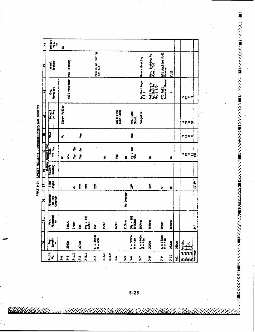
I
41
EP5
%C4
on .;
.5'
0 '0
4,4. 1, '4
Pi AO 'A A.
:B-2
S5.!
* •1. - . ... . I.4. K.94
I-,'~E N N;~"L1,
B-23 .'
ii

?� *�* **� **�* �J . -- -. -� -' -. -� .. .�
S.
S.4'
'SI.
S. .4
'7 0
N @� -
.3 4
* j(j�
* 8. 2N �' 4
zS� C N - - '�
�Is Sn"
I -�-'�
In
U I'2' A I
I-� I
4 - -
- � � ----- ___- 'SK___________________ ii' H hi �* F��i � '� �-
'1 hiI---' S I-
I' �
-: - N coca.I � _________ �
7 .71 8-24

'I
Ii
I4' -
4'1 - @0,P d•0A, f
B-25

T s .I | |
°,.•.. '
"APPENDIX C
DC-7 IMPACT TESTrj
This appendix contains a review of the data in Reference 15 pertaining to the
"Full Scale Dynamic Crash Test of a Douglas DC-7 Aircraft". This test and theL ] test reported in Reference 16 were outstanding efforts to obtain impact data
vital to assist in the search for safety improvements.
°.°1
F]
*.1." I
"'-, C-1

APPENDIX C
Full-Scale Dynamic Crash Test of a Douglas DC-7 Aircraft (Reference 15)
OBJECTIVES: The purpose of the test was to obtain environmental data to study
fuel containment, and to collect data on the bahavior of various components
aboard the aircraft. Separate experiments include the following:
.2. ingfuel spillage studies3. Cokpitcrew seat experiments
4. Crgorestraint experiments
5.1Forardcabin fwd facing passenger seating experiment
6 Childrestraint experiment
7. Wing center section forward facing passenger seatingexrint adkick-up load experiment
8. Aft facing passenger seating experiment
9. Galley equipment experiment
10. Air bag restraint experiment11. Aft cabin fwd facing passenger seating experiment
12. Side facing passenger seating experiment
FACILITY: A special runway was constructed of soil-cement to support the
weight of the aircraft during acceleration. A nose gear guide rail was
constructed of a railroad rail laid on a reinforced concrete base. The craft
was accelerated for a distance of 4000 Ft. reaching a velocity Gf 139 knots atimpact. Impact barriers (in tin~e sequence) were (1) special barriers to
remove the landing gear, (2) an earthen mound for left wing impact andsimulated trees for right wing impact, (3) an 8-degree slope for initialfuselage impact, and (4) a 20-degre slope for the final impact.
C-2

APPENDIX C
t- INSTRUMENTATION: Sensors included the following:
35 acceleration vectors of fuselage and seats,
10 acceleration vectors of dummy pelvis (5 dummies),
6 pressure (fuel tanks),
13 seat leg loads
5 seat belt loads
1 velocity of aircraft
"12 onboard cameras, and
13 exterior cameras
Recording media incuded one 14-channel FM-FM onboard tape recorder with battery
power mounted in a protective box. Subcarrier oscillators were used to allowI 7-channels of data to be recorded onto one channel of tape. Two tape channels
IWO were dedicated tc tape speed compensation and test time/event correlation.
Cockpit environmental data was gathered VIA a telemetry system. Cameras were
operated at 200 and 500 frames/sec. Time correlation was provided by a 100Hz., .01%, square wave recorded on tape. Correlation between onboard and
exterior cameras was provided by flashbulb.
h/ RESULTS: Aircraft velocity at impact was 15 knots faster than planned. Theright main landing gear rebounded from its barrier and struck the right
/ horizontal stabilizer, cutting off the outboard section. A blade from No. 3
/ wengine propeller passed through the fuselage causing some structural weakening,61 damaging a camera mount, and ripping one of the forward facing seats apart.
The fuselage broke during impact with the 8-degree hill. Both wings failed at
S-. the wingroots. The aircraft impacted the 20-degree hill about 10 feet from
. the summit and bounded over the hill. Final impact occurred at the foot ofthe hill about 860 feet from the main landing gear barriers. Several small
fires occurred as a result of ruptured fuel and oil lines.
.54
C-,3*4,j
Im4,
-4c-

APPENDIX C
A voltage control regulator failed in the onhoard data recording system
resulting in the loss of all electronic data in the onboard recorder. The
telemetry system provided acceleration and force data from the cockpit. Two
camera mounts failed allowing the cameras to point away from the intended
fields of view.
43
I C-4

/,
I
APPENDIX D
TEST PROGRAM
SThis appendix. provides an outline of the details of some of the static andimpact tests which are being recommended in Section 12 of the report to assist
in the simplification and improvement of the accuracy of aircraft 'structure
,impact analyses.
Brief descriptions are given of test purpose, test specimens, test set-up and
the data to be recorded. The tests outlined in Section 1 of this Appendix are
1.1.0 Landing Gear Tests
* 1 1.2.0 Fuselage Tests
1 1.3.0 Seat Tests
Instrumentation and usage is discussed in Section 2 of this appendix.
-D-
1.$
• t I
D-
_________- i D-1

APPENDIX D
r
1.0 TESTS
1.1.0 Landing Gear Tests (Ref. Test 12.2.4.1)
Purose
o Correlate static load-deflection characteristics and. static
strength with response under dynamic loading.
0 Determine degree of penetration of gear or supporting
structure into wing or fuselage.
o Obtain characteristic load pulse shapes at gear hard points.
o Deteinine relationship between impact velocity and antgle toacceleration response at various points ont wing structure orwithin fuselage.
o Landing gear and supporting structure.
o Attached -wing - section- (from rear- spar --aft-) - or - fusel age-section to the extent feasible.
Test Setup
Static.
Load specimen on tower track until fracture or crushing
failure occurs.
D-2

APPENDIX D
Dynamic
Gear drop from drop tower.
Weights to simulate aircraft mass.
Impact onto inclined plane.
v
7 1LA140II46 &AIR/Wwt1
OPrO? TC-ST
Data to be recorded
7 . Specimen type
Weight
Drop height
-- - Impact angle
Accelerometer traces
* Strain gauge traces
Pre/post-impact photos
Motion picture records of failure sequence.
b D-3
'WN
APPENDIX D
1.2.0 FUSELAGE TESTS (Ref. Test 12.2.0.2)
Purposes
o Determine static force-deflection characteristics.
o Correlate with impact response.d
J
o Determine modes of crushing of underbelly structure.
o Determine net impulse required to bring about a fuselage
2 break.
o Determine typical floor acceleration response to
fuselage impact.
0 Determine typical seat and occupant accelerationresponse.
S~Specimen
i o Fuselage sections, each consisting of a minimum of three
bays in order to account for longitudinal buckling, and
'. containing:
- o Complete floor structure.I
0 Seats.
0 o Anthropomorphic dummies (drop tests only).
.D -
! ~D-4 .

APPENDIX D
t ~Test setup.
Static
Mount specimen in ground cutout.
Apply loading through cables.
• . / j•NDa R 1 e LL'I"
• i FIGURE D-Z.:
"FUSERAGE0 STATIC CARUSH TEST
Dynamic
• " Drop tests.
~*' tSuspend specimen from sling.
FIGUAE D-0
FUSCLA6e DROP TEST
Step impact plane in some tests to stuudy fuselage break.
7 •:.
I, IFI6URE D-4: FUSELAGE I3REfmK TEST
0-5
S. , , P* -K, -,-... "*-•• •'

APPENDIX D
Data to be recorded--.
Specimen type
No. of bays
I Weight
Drop height
Impact area configuration
material (California bearing ratio).
Accelerometer traces at various points
floor* seats
dummies
*Pre and post impact still photos
Motion picture records.
'D-

APPENDIX D
1.3.0 SEAT TESTS (Ref. Tests 12.2.4.3)
Purposes
Evaluate current static load design criteria.
Correlate static and dynamic response characteristics.
Determine static load-deflection properties.
Specimens
Standard airline seats in two- or three-seat clusters.
Some specimens to include floor, tracks and brackets.
Test dummies.
Test Setup
Static
Loads to be applied in each of the three primarydirections: down, forward and lateral, and in
combinations.
Dynamic
Inertial loading to be applied by use of sled facility,or, if feasible, drop tower.
D-7

APPENDIX 0
Data to be recorded
Specimen description
Weight
Load orientation
Impact velocity
b Floor or base accelerations
Aceeain tpiaysrcua ebr
Acelrations at primary structural members
U, Motion picture records of impact sequence history
.1 Sequence photographs of static response
Pre/post test photos.
IP
D-

APPENDIX D
2.0 Instrumentation
71 All tests which include planned damage to the test specimen are to be
instrumented with double or triple redundancy to assure that, at least,>- Lthe critical parameters are not lost due to instrumentation component
failures. This will invclve duplicate transducers, where feasible,
* duplicate umbilicals and completely isolated data recording systems.
"Data recording media will include a digital data system, an analog system-1 including low frequency strip-chart recorders and high-frequency
"o scillographic recorders, and magnetic type systems for analog data.
.1M Umbilical cables, even with judicious use of data multiplexers, may not- be desirable for use on some tests. In these cases data telemetry
systems will be employed.
Impact Tests
The method commonly used at this facility to record data. from impact
tests of short e•ta duration with high data frequencies is shown
schematically In Figure D-5. The test data is recorded simultaneously onoscillographic recorders and magnetic analog tape recorders. Following
the test, the magnetic tape is played back at an appropriate speed
reduction and the data is digitized and stored on digital magnetic tape
for later use in data analysis. Oscillographic records are used to
determine if the sensors were operating properly, and- if -the- test ......
conditions (velocity, attitude, etc.) were in the expected range. Thedigital data is used for computations, data presentation, and correlation
with predicted responses.
D-
//

- .- -r
% AAPPENDIX D
.!4
%N
TEST VISI(O'DERSPECIMENA
"i • ~CONDITIONING '
% FAS•! MAGNETIC
a COMPUTER
_-,u__c_ •lDTiT__
MAGNETICTAPE
-RECORDERJill
'"\FIGURE D-5: DATA ACQUISITION SET-UP FOR IMPACT TESTS
D-10
5, / ' .
./1 ../ ". " ' •- .•"*/ , '/ • "'

APPENDIX D
Static Tests
Some static tests may require load and motion control to determine the
force-deflection characteristics of the specimen. A functional diagram of a
-typical load and motion control system utilizing the SEL 810A computer is
Bshown in Figure D-6. Load control is accomplished by the computer acting
through a closed loop hydraulic system for each loading actuator. A l oad
commnand signal is summed with the load transducer response signal in the servo
conti-oller to produce an error signal. This error signal is used by the
controller to drive the hydraulic flow control (servo) valve to produce zero
error. Motion control is accomplished in a similar manner with the motiontransducer.
The data acquisition function (Figure D-7) can be performed by Perkin-Elmer
3220 computer and 96 channels of signal conditioning in a unit called a
4Portable Test Station (PTS). This system can be used to acquire and process
all quantitative data describing load, deflection and strain. All 96-channels
may be continuously scanned by the computer at a rate of 50 KHz.
D-1

4~APPENDIX D
GDAL
TEST ARTICLE - '
TO DATA SY.STH4x
1*~-V 7,
-. J EV EV EV Y
"T AAM OANI
'9...'.R
"CNETR OVRE
FIGUR D-6: FUNCIONA DIGA ODADMTO O TROL SYSTEMS
1901
MANEI TAP ALM/ ... ,
TAP CONRO .7(L~kW IN

APPENDIX D
5<%
TEST ARTICE GIMRAL
* -/ '.(Ref Fig 2
*~ LWAD CONTROL
\PA i1IOcwFig) DAC
and natio ATrENVATIC
(PTS
dRECORDER GRAPHICS GrRAPHIC
(BECKK4) WMr~ACE DISPLAY~
LINE-~ PRINTE (TEST DATA)
FIGURE D-7: FUNCTIONAL DIAGRAM - DATA ACQUISITION SYSTEP
0-13

APPENDIX D
Load Measurements
Test loads will be measured with multi-channel strain gaged load cells. Theseunits are calibrated in both tension and compression before installation on atest and at regular intervals thereafter. Accuracy of these units is within+1% of full range. Load cell rating will be selected to match maximum
expected load as closely as possible to provide maximum sensitivity.
Strain Measurements
Metal foil, electrical resistance, epoxy backed strain gages will be used for
strain measurement. Gage type will be selected, to match the thermalcharacteristics of the material to which they are bonded. Gages will be wiredin electrical bridge type circuits, using dt~my gages for bridge completion asrequired by the type of gage installation. Gage circuit resistance will bemeasured and recorded for use in determining stress factors. Each gageinstallation will be photographed and the record filed in the library. Gageswill then be encapsulated to provide protectioni against abuse and moisture.I
D-1

APPENDIX D
Displacement Measurements
A variety of transducers are available for the measurement of displacement.
They -include linear potentiometers, rotary potentiometers, strain-gaged
bending beams, and linear differential transformers (LVDT).
Acceleration Measurements
The majority of accelerometers will be trn-axial. This is necessary to
accurately record the angular response of the component under test. It is
A particularily important for dummy -accelerations to be recorded tni-axially
because of the complex reorientation of the dummy relative to the restraint
system during impact.
* I
.. 5
.!
/D-152..at

APPENDIX D
Photographic Coverage
Video tape recordings of the specimen at selected viewing angles will provide
* a low speed visual record of the test and to permit .nstant replay. The video~
* tape system is too slow to capture the motion initiated at impact, therefore,high speed motion picture cameras will be required.
Motion picture cameras are available with frame rates from 2 frames/second to
11,000 frames/second. These cameras (16mm) will be located at selected
viewing angles and at selected frames rates to provide redundant coverage.
Cameras operating at high frame rates will be triggered to start recording at
- the time of impact (minus a time allowance for the film to reach constant
speed). This is to assure that the camera does not run out of film before the
specimen comes to rest.
A major problem with obtaining photocoverage at high frame rates, especiallywith color film, is that of providing enough light. Also, light reflections
ican obscure the scene. A tradeoff between frame rate and lighting will be
*necessary -for each test. Light reflectons may be minimized by painting the
specimen.
A grid line background will be provided on and near the specimen within the
cameras field of view for use in data reduction.
Timing marks on the film will be provided with a 10,000 Hz., 0.005%, signal
generator providing timing resolution up to 100 microseconds per "pip"--
depending upon frame rate.
* Photographic stills will be taken before and after the test as appropriate to
assess the amount of damage.
Onboard cameras may be required on fuselage tests to monitor selected seat anddummy motion to determine body flexures and contortions during primary and
secondard impact.
0-16

APPENDIX D
Biological Experiments
It is not believed that animal experiments would be useful in obtaining bone
impact injury data applicable to humin subjects. However, physiological
responses such as cardiac and respiratory irregularities may indicate a
A', closeness to physical incapacitation.
Rats could be used in a protected environment containing air bags or other
energy absorbing material such that bone fractures due to nard impact would
* not occur. Electrocardiogram (EKG) and respiration data could be recorded
during end follo 1eing the impact test to (1) determine if physical:' incapacitation occurred and (2) to monitor the rate of recovery.
"Special instrumentalon for this type of measurement has been developed and is
used regularly at this facility in fire tests and toxicity experiments. The
onset of cardiac arrhythmia has been found to correlate very closely withphysical incapacitation whether or not in the presence of toxic gas.
4
• \ I
p 'N
S0D-17
"________ -* ' * \* -
APPENDIX E
REVIEW OF THE "AIRCRAFT CRASH SURVIVAL DESIGN GUIDE"
Volumes I to V of the "Aircraft Crash Survival Design Guide" listed asReferences 1 to 5 have been reviewed and much interesting data contalinedtherein gave rise to the following commients. These conmments are grouped intor the following subjects.
1.0 Structural Design Philosophy
2.0 Impact Environment
3.0 Impact Response
4.0 Concepts for Impact Tolerance Improvement
5.0 Design Methods
6.0 Design Requirements and Design Data
E-1

* APPENDIX E
10StructuralDeinPloph
S The latest version of the U.S. Army Aircraft Crash Survival Design Guidedevotes a 270 page Volume III (Reference 3) to structural aspects ofimpact tolerance and Volume IV (Reference 4) to design of seats,
9restraints, litters and padding. The design philosophy expressed divides
the protective function of the structure into two areas: (1) the landinggear, fuselage and outer structure are to absorb as much of the impact aspossible while the fuselage maintains a 2rotective shell about the
'~-* joccupants, within which no crushing takes place. (2) seats and restraintsystems serve to keep the occupants within the protective shell and tolimit accelerations imposed on the occupant during the im~pact sequence.
-7 A third function of structure is to reduce the likelihood of fire and
-. ~ toxic environment; this topic is treated generally in Volume 5 of theDesign Guide, which is devoted to post impact survival. But f rom the'viewpoint of protecting the occupant from impact load, the approach is
1-Y .simply and reasonably expressed: (1) reduce loadings before the occupant
* / Iis subjected to them (2) protect from direct impact and have his seat and
restraint system attenuate his accelerations.
V'
*E-

APPENDIX E
2.0 Crash Environment
There are various levels of generalizatloi at which the definition of.crash design conditions can be made. The principal approaches are two.At perhaps the most general level of abstraction, the "design impact" isdefined in terms of velocity changes and terrain conditions; these, limitsare placed upon the structure response, in terms of volume reduction,
maximizing G-loading experienced by occupants, maintenance of post impactegress, etc. The Design Guide (Reference 3, Page 56) contains a summaryof such an approach under the heading of "IPerformance Requirem'ents'(reproduced in Table E-1).M
The second major point of departure for design definition is to provide
acceleration pulse shapes for certain critical structural components, andto place design limits upon their dynamic response. This is an, approach
* which is more in line with the tradition of specifications for aircraftstructures, where usually the only significant difference being that 44
dynamic ather than static loading is specified. The Design Guidecontains a number of specifications of this type. For acceleration,input or idealized triangular pulses are imposed at the cabin floor level
Snear the aircraft center of gravity. A summary is given in Table E-2 andthe Design Guide recommends that the~se pulses be used for the design ofrestraint systems, seats, cargo restraint and other items inside the
* aircraft. The acceleration pulse conditions were deirived by estimationfrom accident investigations of crashes over the periods 1960-65 and1970-76.
J:
E-3
.A., J

* TABLE E-1: PERFORMANCE REQUIREMENTS FOR STRUCTURAL IMPACT TOLERANCE
Impact Imrpacted differentia atitd volumeOther Date
Logtdna2ii 0 no barnard ims otlpedea posatrash Volume Itto pilot/ egg...copilot
40 IS mea. Inward buckling of side NIL-sTO 1290length re- wall* ahoulO not pose Volume U1ductiofi for h&aaaripaea coopcompartment
Lateral Rigid 3 *as* you IS man. Lateral collapse Of oc.- HIL-STD-1290width cuapied area. not barnard- Volume Isreduction ourn. No entrapment Of
limbs.
4Vertical Rigid 42 025't-ls" 15 max. a loads not Injurious to .dIL-STD-l290Pitch height red. occupants Volume Is2 20 moll In pass./
troop cow.-paramant
Resultant Rigid SO Comination As above has. velocity chtangams HIL-ETO-1294for various long. !0: ft/eec Volume H
tam omt Vert. *42 ftosec6..Jlat. 3 0 ft/cac
*.%I 2 ft/sac
NRellover saart * g adeward Minimal Vorward fueelage buried to NIL-BTD-1290or Is** In- (door depth of 2 in. finverted orverted or batche. aet. on side).* Load uniformly
*any Inter- assnumed to distrib,,tad over forwardmediate a&gle he non-load 256 of occupied fuselage% arrying) length. Can ewataim 4 0
withou~t injury to m@ated*1~and restrained occPast&.All loading directions be-tween normal and parallelto akin to be coonsidored.
Rollover (post- Rigid too 350, 1S Ms. KIL-SM-1299%impact) Zell@ Wea.) volume re-
* .~4 ductiorn 450
zarth plowing Sarth - - Prclude plowing when for- mUZ -rn-lag-~~ - Cecpig word 250 of Iweelage hue~.-(longitudinal) uniformly applied vertical
load Of 10 G and rearward% A load of 4 G or the ditch-J* Ing loads of NIL-k-0086ISA,
-- V ~.whichever i. the greatest.Landing gear Rigid tie*1 sell None. Plan- Aircraft deceleration at NIL.-SO-1290
110' Pitch tic deforms- normal G.V. for impact-4 tion of gear with no fueelage to ground__and mounting contact. All other A/C
A s ----------- ____- ystem at- structural parts. ;xesptlowable blades, sbould he flight.
r ~worthy following9 crash.
.W ~' andng ea lc 10 10g.' -5 Pich 5 m.. No rollover, or if rollover 11IL-VID-129014 Vert. 2180 Roll volume to- occurs, two 3600" roll*
#20* tow duction (So without fuselage cruehing Volume 1arred I
aI Light fixed-wing aircraft. attack amA cargo helicopter*..b I Other helicopter*.cl velocity at impact. not differential.
(REFERENCE 3, PAGE 56)
E -4
'S_

APPENDIX E
TABLE E-2: SUIMARY OF IMPACT CONDITIONS FOR HELICOPTERS AND
LIGHT FIXED-WING AIRCRAFT DESIGN
Impact PulseDirection Velocity Peak Duration,(Aircraft Change, Av Acceleration at
Axes) M/S (FtiSec) (G) (Sej, Comments V
Longitudinal 15 (50) 30 0. 104 Triangular(Cockpit) deceleration U)
pulse:- Gpea " kAk
Longitudinal 15 (50) 24 0.13 . At I"
(Cabin) ft I'-
Vertical 13 (42) 48 0.054 \:
Lateral 8 (25)a 16 0.097 t calcu-lated from
9 (30 )b 18 0.104 known or I "assumedvalues forGpeakand v:-At ( &v).",i')
At Gr k •J-i
a) Light fixed-wing aircraft, attack and cargo helicopters.*b) (ther helicopters.
(REFERENCE 3, PAGE 47)
Si
~* ~ A.... ~ y*Ni.....•**.-* \;-. >'£

APPENDIX E
With the floor-acceleration-pulse-sperifications approach, another
11 essential ingredient where the occupant response is concerned is data for
human tolerance level. As discussed elsewhere in this report, this data
"appears to be scattered, sometimes contradictory and usually limited to
an idealized occupant (the army aviator). Nevertheless, it helps to
"- "4 define the designer's objective confining his job to provideoccupant-protection devices to keep response within tolerable levels,
given specified input accelerations.
"- In developing design requirements and procedures for civilian transport
category airplanes, the starting poli.ts will be the same as those taken
i • the Design Guide. Overall definition of impact conditions will
"/ ' encompass either velocity changes (along with airplane attitude at impact
/ [1 and terrain conditions) or prescribed acceleration pulses. Actualvalues for transports must certainly be different from those for any
helicopters, and must be established from the results of extensive test
S -programs.
EI
y.:'
• " •jE-6

r.~~~ .. ..ca~ .-r . .~. .. .. .. . -. - -.* - - -. - --a.
A.46
APPENDIX E
*3.0 Impact Response
PThe Design Guide contains a general descript ion of structural damagewhich frequently results in occupant injury (Reference 3,, Page 51).
Longitudinal loads are first experienced by the forward and lower partsw-of the fuselage. Earth scooping enhances loads at the forward fuselage
Iand often causes collapse. Breakup of more structure causes it to be'. ~pulled beneath the rest of the airplane and results in higherPlongitudinal acceleration than would be otherwise experienced. Landing.4' gear is not effective in absorbing crash energy.
Vertical impact loads on the fuselage shell are enhanced by large massitems attached high on the fuselage. Excessively high impact. loads
4 limits for the lower fuselage structure will result in transmission ofhigh vertical accelerations. to occupant, causing compressive spinalinjuries.
High lateral loading is a -frequent occurrence in military helicopteraccidents, but would probably be of less serious concern for largetransports. An important design considerations is to restrain theoccupant from contact with the fuselage shell.
Bending loads on the fuselage shell occur in impacts at high impact
angles and cause rupture of the fuselage, exposing some occupants todirect contact with j gged metal and loss cf restraint.
Floor buckling can educe the effectiveness of seats. The energy-absorbing mechanisms of the seat (usually effected by some form of
plastic yielding) shou d come into play neither too early nor too late inthe impact sequence. well-designed seat attempts to be load limiting,but the seat response epends upon the response of the occupant as well(Reference 4, Page 20). A typical picture of seat-occupant response is
E-7

APPENDIX E
shown in Figure E-1 for a "load-limited seat". It is seen that the seat pan
acceleration response and the occupant acceleration' response curves oscillate
about the limit-load factor. These dynamic overshoot phenomena require
analysis by seat-occupant response codes, and considerable testing in order to
develop an effective seat design.
.E-

'1APPENDIX E
FIGURE E-1: TYPICAL SEAT PAN, DUMMY CHEST, AND DUMMY
PELVIS RESPONSE TO VERTICAL IMPACT LOADING
(FROM REFERENCE 4)
45etpn sldInitial spike Input pulse (heavy solid)
-00Vertical dummy chest (dotted)- Vertical dumy pelvis (dashed)-
30
01
0 %-
0
- -- Iital otc - Secondary notch
-15 .0 0.05 0.10 0'.15
Time, sec
*16
~>1 E -9

"APPENDIX E
4.0 Concepts for Impact Tolerance Improvement
.- The Design Guide discusses a number of devices and concepts for
structural design to improve Impact tolerance.
Design for breakaway of wing and empennage under high impact loading is
recommended so that the high forces otherwise needed to remove their
kinetic energy during the impact need not be transmitted through the
"fuselage. This would tend to reduce the accelerations experienced by
occupants. Wing removal also provides the means of leaving flammable
- .fuels well behind the fuselage (Reference 3, Page 149).
le .Breakaway of landing gear has little effect on fuselage loading; the
principal concern with gear breakaway is in controlling its trajectory in
order to avoid pOnetratior of fuel tanks.
"Design considerations for fuel tanks are listed at Reference 3,
Page 152. These are primarily concerned with reducing the likelihood of
rupture.
/ Recommendation its made that large mass items be kept from position high
in the fuselage so that sidewall collapse would be lessened and the* 1 possibility of !the upper fuselage dropping upon occupants would be
reduced (Reference 3, Page 133). In this regard, low-wing configurations
should be more impact tolerant than high-wing configurations.
The analysis given in the Design Guide (Reference 3, Page 116) indicates
the effect of earth plowing, where the crash involves the scooping of
soft earth which is driven to the velocity of the aircraft. The effect
* •on the average acceleration is said to be
a- ME * VO.1 , a mA+mE • t-
a t
E-1O
' • -
- -V /,, --- . ,..-.- ,.,.:.-; . • ., .r.;..., / ,.,,,, ., : -

APPENDIX E
where mA is the* aircraft mass, mE the mass of scooped earth, Vo theinitial impact velocity (longitudinal) and & t the impact duration. Thusreducing mE will reduce the acceleration. (The' formula given is notvalid for small mE/mA since the limit value is zero.) The DesignGuide also gives a formula for mE:
ME * KAVodt' where K is constant and A is the cross section area ofthe earth gouge. This formula is given without any verification.
In any case, it is clear that earth scooping increases longitudinalloads. The Design Guide reconmmends a strong nose structure so as toprevent the formation of a "scoop", Figure (E-2). Actually,consideration of this design involves a tradeoff between on-runway andoff-runway situations. For crash landings on the runway, which are
9v, probably the predominant type of survivable crash condition, designingfor collapse of the lower fuselage is preferable to keeping it rigid.
ix1

K APPENDIX E
n.,
Eath
FIGURE E-2 MEHDO RENOCN NOESRCUET PRVD ICEA D
FIGURE E REFEMETHDCFEINOCN NOS STRUTUR TOPOVD5ICEAE
E -12

APPENDIX E
Various fuselage design concepts (illustrated in Figures E-3 and E-4) are
directed toward reducing plowing, absorbing energy by crushing of the
Sunderbelly and keeping floor, sidewall and exits intact. In transports,
use of foam and other types of reliable material (Figure E-5) would
involve a very expensive reduction of cargo space. More appropriate
would be consideration of concepts which utilize the energy absorbing
capability of lower fuselage cargo.
SVarious energy absorbing devices are illustrated which involve metal
working, (Figure E-6). These devices appear to be the most efficient
from the point of view of specific energy absorption (energy absorbed per
unit weight), but the unidirectional nature of their effectivity limits
the potential areas of their application. The Design Guide notes that"some may be included in the primary aircraft structure to help control
the deformation sequence during a crash; however, none are applicable for
use as major structural members, such as beams," (Reference 3, Page 99)
Essentially, these devices will find application as local limiting struts
in seats and other restraint systems.I
The Specific Energy Absorption (SEA) of materials is an important measure
"•f their usefulness for structural crashworthiness. The material SEA,* S
which is related to ductility, is the area under the stress strain
diagram, divided by the specific weight. Figure E-7 illustrates the
tremendous advantage of metal over composites. The Design Guide *at
Reference 3, Pages 81-97 contains a good overall discussion of the
i potential for composites in crashworthy design, and seems to show that
the advantages which these materials offer in terms of strength-to-weight
ratio are offset by their poor SEA capability. The Design Guide suggests
use of components in crushable heams and bulkheads (Figure E-8) and in
tubular items designed specifically for vertical impact energy absorption
(Figure E-5).
The low capability of composites to resist and distribute concentrations
of stress seems to require adjunct use of metals in joints and fastenings.
t E-13
.-*--....-. .

APPENDIX E
Reinforced exits
"'"• Strong rollover' • •:structure
* Energy-absorbingconstructionudrfuselage
Local strap Strong floor forreinforcement seat attachment
Frangible fittings provide Seats and other
for jettisonable equipment nonbreakaway 4ui•-which will not impinge into ment providt. with
crew compartment filament-woundsecondary equipment
Sandwich-stiffenedring frames preventinward buckling
Side fillets* prevent inward
buckling offrames
Squared S
corners providelateral energy 30i"absorption for impactoblique impact
SFIGURE E-3: OVERALL FUSELAGE CONCEPTS. (FROM REFERENCE 3, PAGE 89)
E-14
S. • •••• .•. • .••,••. •......, - .,• • • • .x,• • v '' ,•i

APPENDIX E
I.
* .
(a) (b)
Circular cross section to Strong sidewall to preventreduce rollover loads prctective shell failure
%i
(c) (d)
Redundant sidewall frames Crushable material for loadfor rollover loads control and distribution
FIGURE E-4: FUSELAGE SIDEWALL CONCEPTS - LATERAL IMPACT
(FROM REFERENCE 3, PAGE 94)
E-15
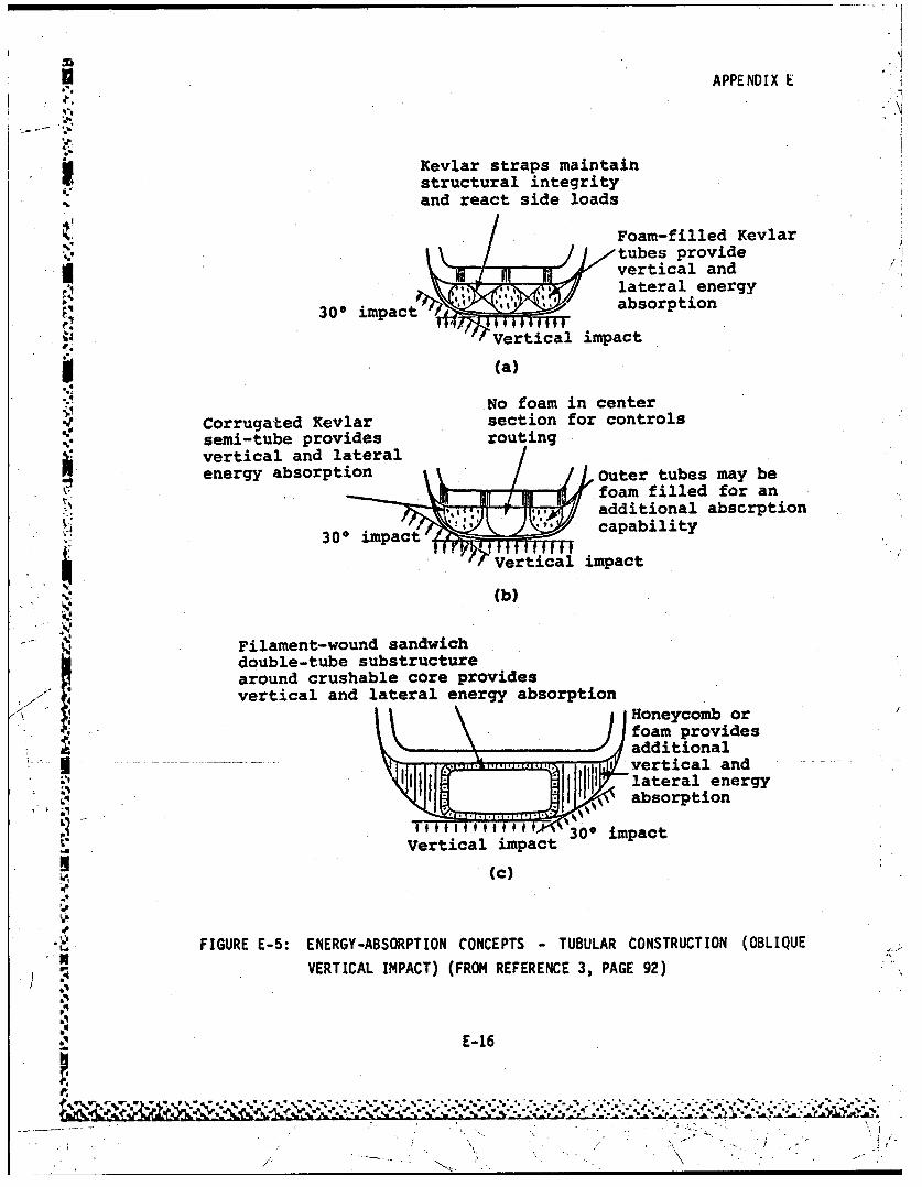
*• APPENDIX E
4.• .. .k
4 Kevlar straps maintainstructural integrityand react side loads
Foam-filled Kevlartubes provideI vertical and
• *', •lateral energy
300 impac ,1 s absorption
Vertical impact
* (a)
No foam in centerSCorrugated Kevlar section for controls
semi-tube provides routingvertical and lateralenergy absorption Outer tubes may be
foam filled for an'• *'additional abscrption
imp capability•': ~ ~300 impact [[•,
SVertical impact
(b)
Filament-wound sandwichdouble-tube substructurearound crushable core providesvertical and lateral energy absorption
Honeycomb orfoam providesadditional
....... . vertical andlt !1 lateral energy61 absorption
,,,,300 impactL" Vertical impactSi
(c)
t-, FIGURE E-5: ENERGY-ABSORPTION CONCEPTS - TUBULAR CONSTRUCTION (OBLIQUEVERTICAL IMPACT) (FROM REFERENCE 3, PAGE 92)
}. :'!
o E- 16
.. 1
__ _ _
/" \ -.-

APPENDIX E
Outer tube-Inrtb
Z Wire/.Slot in inner tube
(a) Wire bending -absorbs energy by plastic bending
of wire over rollers
Thin-walled metal roll tub deomn4I (roll) region(b) Inversion tube - absorbs energy by invert4ag
a thin-walled tube
Wire helix Outer tube
(c) Rolling torus -absorbs energy by rolling~wirehelix between concentric tubes
A~ Deformed
(d) Tension pulley - absorbs energyby plastic spreading of thepulley housing
4 FIGURE E-6: EXAMPLES OF ENERGY-ABSORBING DEVICES (REFERENCE 3, PAGE 100)
E-1 7
% .,.

APPENDIX E
P,
200 A 7 0 7 5
Energy-absorption ratio 77- - 12.3AG/E
" 1 0 0 - 7 0 550
-. .. • SO
i""4
So
'0
, 0 0.02 0.0o4 o.06 0.0 o0 .10 0. 12Strain (in./in.)
S~FIGURE E-7: STRESS-STRAIN RELATIONSHIP FOR ALUMINUM ALLOY (7075) and 0• . • DEGREES GRAPHITE/EPOXY COMPOSITE (REFERENCE 3, PAGE 85)
' 1
.: • E-18
I' D
-",~~~~~~~~~r .7 "4% 'l• " •, .. 7 i_-" ""* , , * .~.... .* - - C* * .2
APPENDIX E.
Deformation of Joints is a serious concern in design of im~pact tolerantseats, and the Design 3Juide Volume IV (probably the best available workon seat design) devotes careful and rational attention to this problem.Inadequate performance of floor structure by excessive warpage, and offloor to seat connections by transmission of bending and torsic-1 momentscan void a well-designed seat. Figures (Reference 4, pages 56, 57,. 58,59, 60) illustrate concepts for Joint design to effect release of momentsor torques so as not to blov:k the load alleviation devices which may bedesigned into the seat.
A review of design concepts for impact tolerant seats indicates that theyshould be designed as mechanisms as well as structure: their kinematicsduring impact response should be predictable. This means that floor andbase structure should not deform substantially; the s!a~t response shouldbe a linkage motion with most links remaining rigid and the energyabsorption function produced by specific lin~ks or connections. Inparticular all designs, specific hinges or struts absorb the energy bysome form of plastic working of metal. Serious design problems -arapresented when force components are presented in all three principaldirections and the stroking function may be impaired due to binding.
The seat design section of the Design Guide contains a comprehensivereview of the use of "stroking" devices which have predictable loadlimiting and energy absorbing capabilities. It would appear that thesedevices, which already find application in all military crew seats, offer,much potential for improving occupant protection.
The Design Guide addiesses the problem of providing differentload-limiting seat capability, depending on occupant weight, andindicates that this goal would be achieved by active or passive devices.Reconmmendation is made that variable limit-load energy absorbers beincorporated in all new (military) impact tolerant seat systems(Reference 4, Pages 92 and 93).
E -19
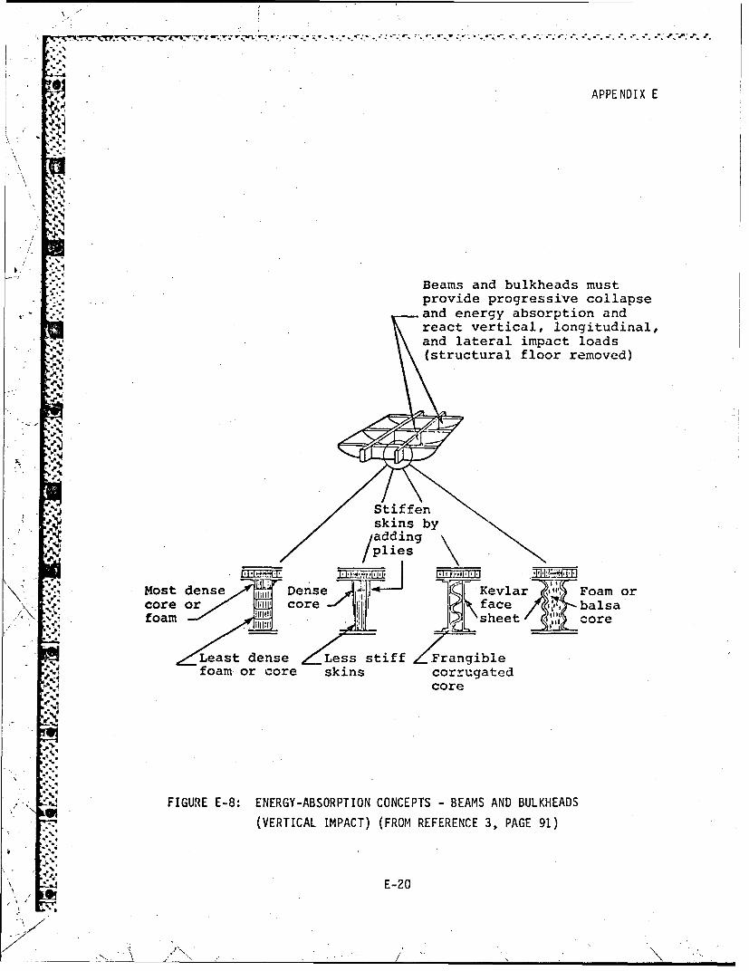
*' .'
APPENDIX E
Beams and bulkheads must* -provide progressive collapse-- and energy absorption and
react vertical, longitudinal,and lateral impact loads(structural floor removed)
N
Stiffen
skins byIaddingplies
Most dense 1 Dense •' 'l-j Kevlar ' Foam orcore or 10 1 core ace balsa
,'\ foam sheet core
-- Least dense Less stiff Frangiblefoam or core skins corrugated
core
FIGURE E-8: ENERGY-ABSORPTION CONCEPTS - BEAMS AND BULKHEADSU• (VERTICAL IMPACT) (FROM REFERENCE 3, PAGE 91)
E-20
,7. - -

APPENDIX E
The Design Guide is mute on the subject of the relative merits of
backward versus forward facing seats, a subject which clearly deserves
the attention of engineers having a serious concern for the Impact
tolerance of transport aircraft.
Use of seat cushions for load alleviation appears to be impractical'Ii (Reference 4, Page 127); rather, their function should be to providecomfort and load distribution. Energy absorption considerations indicatethat seat cushions of thickness rather less than those in current
ci vilian aircraft are in order, because the motion of the pelvis relative
7 to the seat bracket should be minimized (Reference 4 Page 128).
Cushioning materials are recommended for the reduction of secondary
*impact injuries, in particular, head injury. These materials. can serveto absorb energy as well as to distribute the impact from over a larger
-- .. '.:area (Reference 4, Page 219).
Restraint systems are treated in Section 7 of Reference 4 of the DesignGuide. For troop/passenger seats the Guide recoimmends systems whichinclude upper torso restraint (Figure E-9). -These restraint systems
should be designed to hold occupants in the 95th percentile survivable
* .Saccident. Cargo restrain systems (nets and lines) are to sustain 90th
percentile impacts, defined by a triangular impact pulse of 16 G peak(Reference 4, Page 161).
E -21

w* t " * P '.
APPENDIX E
f .1
' 1
" .~ .*J'q
Type I Type II
Item identity
1. Inertia reel2. Shoulder strap3. Lap belt anchor4. Buckle with shoulder strap connection.5. Lap belt6. Adjuster/fitting
FIGURE E-9: AIRCRAFT TROOP/PASSENGER RESTRAINT SYSTEMS
(REFERENCE 4, PAGE 135)
___ E-22

APPENDIX E
5.0 Design Methods
Design techniques of various levels of sophistication and complexity appearin the Design Guide. Kinematics of the most elementary sort are. described(Reference 3, Page 169) and applied to illustrate the properties of various
idealized. pulse shapes. Formulas' and charts are provided which relate
stopping distance to average deceleration (Reference 3, Page 182) and to
peak accelerations for various pulse shapes (Reference 3, Page 190).
Elementary work-energy principles are derived (Reference 3, Page 174).
These energy methods can be efficient and powerful means of gaining a basic
understanding of impact phenomena as illustrated by analyses of earth
* .. ~ plowing effects (Reference 3, Page 116) and of seat stroking (Reference 4,
Pages 70-81). A useful formula for determining required seat stroke
distance is given at Reference 4, Page 76.
Landing gear design methodology is described at Reference 3, Page 195.This discussion is rather elementary and neglects the fact that side
loading which occurs during taxi is usually a critical design condition forSithe gear structure in large transport airplanes.
A number of digital computer programs for simulating structural response in
the impact environment are reviewed briefly at Reference 3, Pages 225-242.\ "~ Attention is given to KRASH, DYCAST and WRECKER (discussed elsewhere in
this report) but little attempt is made to indicate the degree of--------- ionfidence with which a design engineer-could rely on them. For potential
users of KRASH, a very important treatment of means of developing
structural properties is given at Reference 3, Pages 203-224, but theintelligent use of impact simulation programs still appears to be rather anesote ric craft which can be learned only through long and painful
experience. The Design Guide discussions, although somewhat obscure, is animportant step in the direction of helping the average structural engineer
in the use of these complex codes.
E-2 3
'_

APPENDIX E
Various seat occupant computer programs are reviewed at Reference 4,Page 93 et seq., again without supplying much in the way of experimr'Ital
verification.
Testing. is discussed at Reference 3, Page 243 in the context of providingbasic structural data for impact analysis. A study by Holmes and Colton
WI (Reference 6, Pages 561-582) is reported which indicates that scale models
41. can cut the cost of testing' in half for prototype structures in the1000-10000 lb range.V
Volume IV of the Design Guide contains a detailed. list of static testrequirements for impact tolerant seats (Reference 4, Page 182) as well asrequirements for dynamic tests if substituted for static tests (Reference 4r :Pages 189 and 190). A useful list of references to ASMT test methods forflexible cellular plastics is provided at Reference 4 Page 228.
6.0 Design Requirements and Design Data
The design engineer's activity requires data in the form of materialproperties, geometries, conditions, and it also demands design objectives.To these ends, the Design Guide illustrates how these needs might befilled, and to what extent they remain unfilled. The "performancerequirements" for impact tolerant structures (Ta ble E-1) gvsseii
15P ~ impact conditions which 'define the basis for design. Design impactvelocity changes are provided, and it is specified that these velocitychanges are assumed to occur on a rigid surface and with a triangularacceleration-time pulse shape. Generally, the pulse duration does notappear to be specified (and, thus the peak acceleration' level cannot begiven), but this is reasonable since the duration depends to some extent on.~ .the particular structure involved. However, specific floor load pulses aregiven (Figure E-10) and this means that the designer of seats, cargo tie
downs and other important protective systems has a basis to work from. Itis noted that these are dynamic load conditions, rather than static,Static load requirements are specified for seats and cargo restraintsystems, as discussed below.
E -24

APPENDIX E -
It is to be emphasized that the specific acceleration pulses probably
cannot be carried over unchanged for use in transport aircraft design. As
noted earlier, the large transport by its very size places a great deal of
"yielding structure between impact plane and floor; thus peak loads should
"probably be lower for the same impact defined in terms of velocity changes.
Percentile--&- 95th 90th 85th 50th
Cockpit area
30 G 20G 16G1 G
... e
5 0 43 39 28ft/ec t/sc t/sec ft)se3A A
Cabin area_ _4 A AG 13 G 4 G
_ /5 43 A9 282Aft o sec: fsec ft sec /e
* FIGURE E-10: AIRCRAFT FLOOR LONGITUDINAL PULSES FOR ROTARY -AND LIGHT
FIXED-WING AIRCRAFT (REFERENCE 3, PAGE 160)
"16
E-25
Q/

APPENDIX E
Design requirements for impact tolerant seats and for energy absorbing
cargo restraint systems appear to be very specific: the load-deflection
Scurves must have particular characteristics, as illustrated in Figure
E-11. An acceptable design must have a load deflection curve which rises
to the left of and above a specified "base curve", and which attains its
ultimate load above a specified "minimum acceptable load curve". These
loads are static loads, which have been determined from dynai-;c calcuiation
based on specific input floor pulses (e.g. 30G peak triangular pulse of
15.2 m/s (50 ft/sec) velocity cnange in the cockpit and 24G peak with 15.2
rn/s (50 ft/sec velocity) change in the cabin area for the forward load,
"(Reference 4 Page 169). The design requirements for cargo restraint are
similar in form to those for seats. (Figure E-12).
The Design Guide recommends both static and dynamic seat testing and
presents proposed test requirements as well as useful recommendations as to
how the tests should be conducted (Reference 4, Pages 181-195). Figure
E-13 shows the requirements for dynamic testing of seats. Requirements are
also given for research/development which involve off-axis accelerations.
Particular anthrophomorphic dummies are to be . used; with weights
representing pilot/copilot or troop/gunner (with gear). For civilian
transport applications, it would probably be necessary to modify the given
values.
• .•''I - F
514
t E-26
* S •

APPENDIX E
45
FW4a'40 Acceptable failure
~ Sampleacurvesor
o 0
.10
Accptbl fa2ur areatbl
o 20
-44o
4' 10 _ _ _ _ _
:i:i:.Cabkit seats...
0 23 4 68102
mcepasured fatisatreferenca on
FO3R LODADDFETO0EUIEET O L YE
OFAM2ICAF5FRADDEINPLE(RFRNE40AE10
r4R j c i n a e
20 1-Bas crv
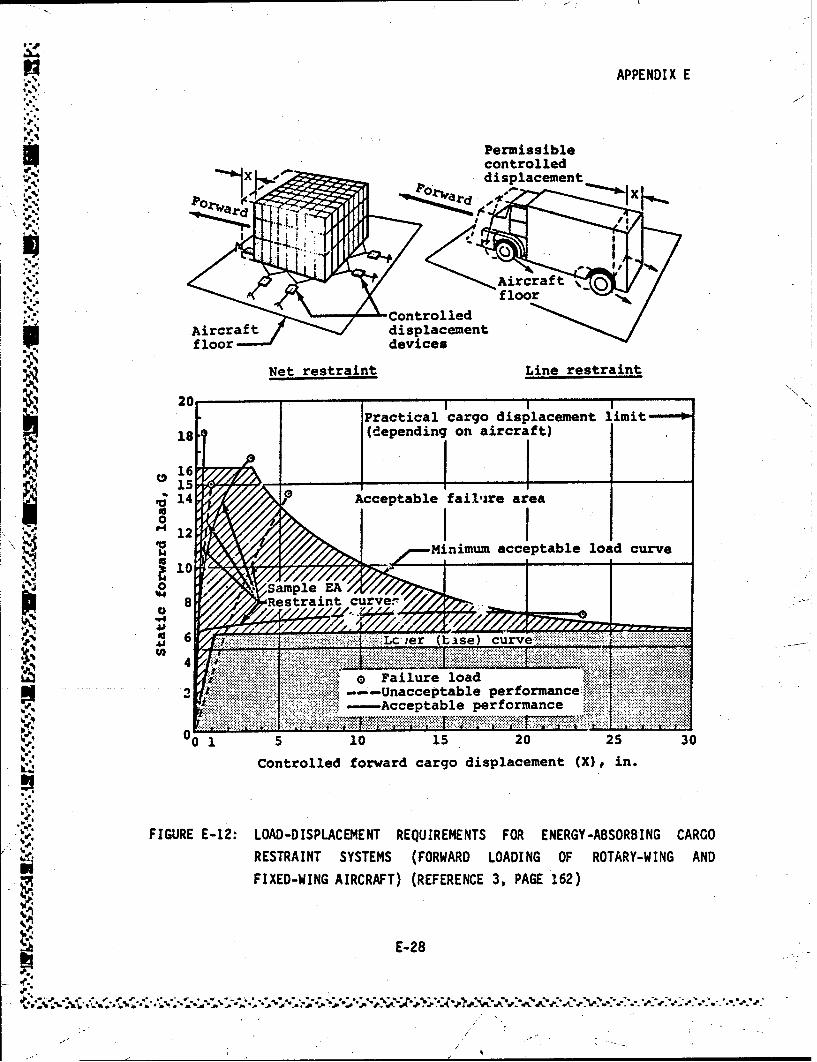
APPENDIX E
%
Permissiblecontrolled
S•. displacement
10 folt.r
AircraftControlled
Aircraftdisplacementdevices
Net restraint Line restraint
Practical cargo displacement limit----*,
18 (depending on aircraft)
~15 _ _ _ _ __ _ _ _ _
14 ?Acceptable fail-zre area
S• : ____•nimum acceptable load curveS 0a4
10Sample EA
S8 ,Restraint curve.-.
.4
o Failure load
-- Acceptable performae !:1::,
U0 1 5 10 15 20 25 30
Controlled forward cargo displacement (X) in.
FIGURE E-12: LOAD-DISPLACEMENT REQUIREMENTS FOR ENERGY-ABSORBING CARGO
RESTRAINT SYSTEMS (FORWARD LOADING OF ROTARY-WING ANDLFIXED-WING AIRCRAFT) (REFERENCE 3, PAGE 162)
E-28
W,,o/

APPENDIX E
'ami
0Ir _
t t I t 2Time. sea
Cockpit seats Cabin seats
To at Cont iguratioi' Parameter Qualification R&D Qualification A
inrial t mec 0.034 0.020 .059 .026I, 2 see ft/mac 0*051 .074 .07t4
Utility and obser-2a vation helicopters ti mac 0.062 0.036 .062 .036
inertial a min is i6 is i6£ load
AV min, ft/mac 30 30 30 20
R3 t2 sae 0.066 0.1030 .100 .100
inertial a2 min 0100 0100 .17 2.20*1 load
LAV min. ft/eec 20 25 1 20 5
'4ý
FIGURE E-13: REQUIREMENTS OF DYNAMIC TESTS IF SUBSTITUTED FOR SIATIC TESTS
(REFERENCE 4, PAGE 189)I~E -29ýA.

APPENDIX E
Static strength requirements for ancillary equipment and component
attachments are specified in the Design Guide at Reference 3, Page 154 andýReference 4, Page 195. These static strength requirements, shown in
Table E-3, are probably very conservative (Reference 4, Page 195) and if
applied to items of substantial mass, "significant weight penalties may be
incurred or the available supporting structure may not be capable of
withstanding the anticipated loads" (Reference 3, Page 154). Probably amore realistic approach would be to lay down requirements in terms ofmaintaining attachment under specified base acceleration pulses. These
would be satisfied by analysis or testing.
The Design Guide contains a sprinkling of tables and charts of very useful
.design data (an index of this could be very helpful for the designer).Examples:
V$o Crippling allowables for aluminum extrusions and formed sections,
Reference 3, Page 216 and 217.
o Material properties of selected flexible cellular polymers,\, ~ Reference 4, Page 226 et seq.
o Ignition conditions for abradod metal particles, Reference 3, Page 98.
o Restraint webbing characteristics, Reference 4, Page 150.
Finll, t~_Guide contains an extensive but carefully selected list of
references to technical works and each volume of the Guide is graced withan index.
E-30

-• APPENDIX E
-4
TABLE E-3: STATIC LOAD REQUIREMENTS FOR
ANCILLARY EQUIPMENT ATTACHMENTS(REFERENCE 3, PAGE 154)
., Downward 50GUpward lOG
Forward 35GAftward 15G
Sideward 25G
""4 ("
*19
I 7
E-31
hi-
/ i

APPENDIX F
HUMAN TOLERANCE TO IMPACT
This appendix contains a discussion of human tolerance limits to loads
1 experienced in aircraft impacts. Indices and criteria applicable to spine
loading and head impact are given prime concern. The tolerance test data
appears to apply only to military personnel although Figure F-5 gives an
indication of the variation of the tolerance limits for a wide. range of ages for
the flying public.
The discussion on human tolerance limits and index indicatovs covers the
following:
1.0 Dynamic Response Index
2.0 Cther Spinal Models
3.0 Head Injury Criteria
4.0 Leg Injury Criteria
5.0 tiff.-Axis Acceleration
6.0 Shock Spectra
7.0 Flailing Distance and Volume Reduction
F-1

APPENDIX F
1.0 Dynamic Response Index (DRI)
The "Dynamic Response Index" is a simple measure of spinal injury severityresulting from short duration acceleration applied in the upward, vertical
direction +Gz (to compress the spine). The index is the output of a
one-degree-of-freedom spring-mass-damper oscillator whose parameters have
been determined from vibration and impact tests of humdn subjects and
cadavers. This model is embodied in a single equation
5.Uz
governing the compressive deformation S of the vertebral column. The input
"z is the applied vertical acceleration (e.g., at the seat bucket). The
parameters of the system are
Ou ,thenatural frequency
z k/m where
k = stiffness
m= mass
." = damping ratio
For a given input acceleration pulse 'z. The maximum deformation c max.
.J determine the Dynamic Response Index (DRI)
4'-. DRI -
where g is the gravitational acceleration 9.81 m/s2ec.
Thus the DRI is a measure of the peak acceleration response level.
F-2
"l, -/ ,..• ,N . /

APPENDIX F
The DRI model has been shown to correlate with spinal injury rate in
aircraft seat ejection studies (Figure F-i). It has the advantages of
simplicity and ease of incorporation into aircraft impact response computer
.-. programs of the finite element or lumped mass variety, such as KRASH,
DYCAST, ACTION, SOMLA, etc.
For design of adjustable, upward, aircraft seat ejection systems,
MIL-S-9479B (USAF) uses
O -= 52.9 radius/sec.
0 o.224
In application of the Dynamic Response Index, is should be borne in mind
that the model is useful in predicting spinal injury and compression
loading, such as would be expected in seat ejection response or perhaps in
"aircraft impacts where the occupant is restrained by a shoulder harness.
However, the typical airline passenger impact position (body folded
forward, lap belt restraint) will usually develop extensional loading of
the spine; and here DRI application may be questionable.
Jh%
.F
I
F-3
-~ r i7

.. *.• * - ~ .*.* " ", , , ,* "" " ,* - ,* "* " .*. , , - , -. '-"
APPENDIX F
:.-
50O- - Operational data /40- Cadaver data /
0- ave /d/20 200
% 10 /
5 / A
2-
-5-
Dynamic Response Index
,.o.;iAircraft type Nonfatal ejections
:..'• A*64!'• : B*62
, . C ... . .65•- I• D* 89-'
,•..E 33SF 48
|• *Denotes rocket catapult
a.- FIGURE F-i: EXPERIMENTAL VERIFICATION OF DYNAMIC RESPONSE INDEX'.• (REFERENCE 2, PAGE 66)
1F-4 -8
* ~A 64/ 7
j , -. VI . * , . -
-• . ', / *

APPENDIX F
2.0 Other Spinal Models
Elaboration on the principles underlying the Dynamic Response Index model
leads to detailed, multi-degree-of-freedom models of the spine, with
individual vertebra treated as rigid bodies connected by deformable
elements. King and Prasad have developed a 78 degree of freedom model
which simulates spinal motion in the mid sagittal plane (the body plane of"symmetry"). (J. Appl. Mech. 4, 3 546-550, 1974). Belytschko, et. al. phave developed a three-dimensional model which includes vertebrae, pelvis,
head and ribs. (USAF AMRL TR-76-10, 1976). Summaries of these two models
are repeated by Laanenen in Reference 2, Page 67.
Used by themIselves, these models promise much utility for predicting
details of spinal response, but they would appear to require a fairly
complex and sophisticated data base as well as a we.ll-correlated means ofinferring spinal injury potential from their output. It is not clearwhether suchl means currently exist. Moreover, the demands made by
multi-degree-of-freedom biomechanical subcomponent models upon computer
core and processing time would tend to rule out their incorporation into
general aircraVt impact evaluation computer programs, at least at present.
F-5

APPENDIX F
3.0 Head Injury Criteria
Studies of head impact tolerances have resulted in a number of injury
criteria. Reference 1, Page 48 identifies four different types.:
peak G
f-.' peak transmitted force
Severity Index (SI)
• Head Injury Criterion (HIC)
The "Wayne Curve" has been developed at Wayne State University from
extensive study with cadavers and anlmals. This criterion shown in
Figure F-2 is intended to show impact tolerance for the human brain in
forehead impacts against plane, unyielding surfaces. The tolerable level
depends upon both acceleration and duration.
The Severity Index developed by Gadd is a single number which was proposed
to account for the relatively higher dependence of Injury on acceleration
as against duration. From a history a(t) of head acceleration in impact
from time to to time tf (in seconds), the index is calculated by
SSI =a n dt
____where alg is the acceleration-ng gIs
.F-
- ,4
• F -6
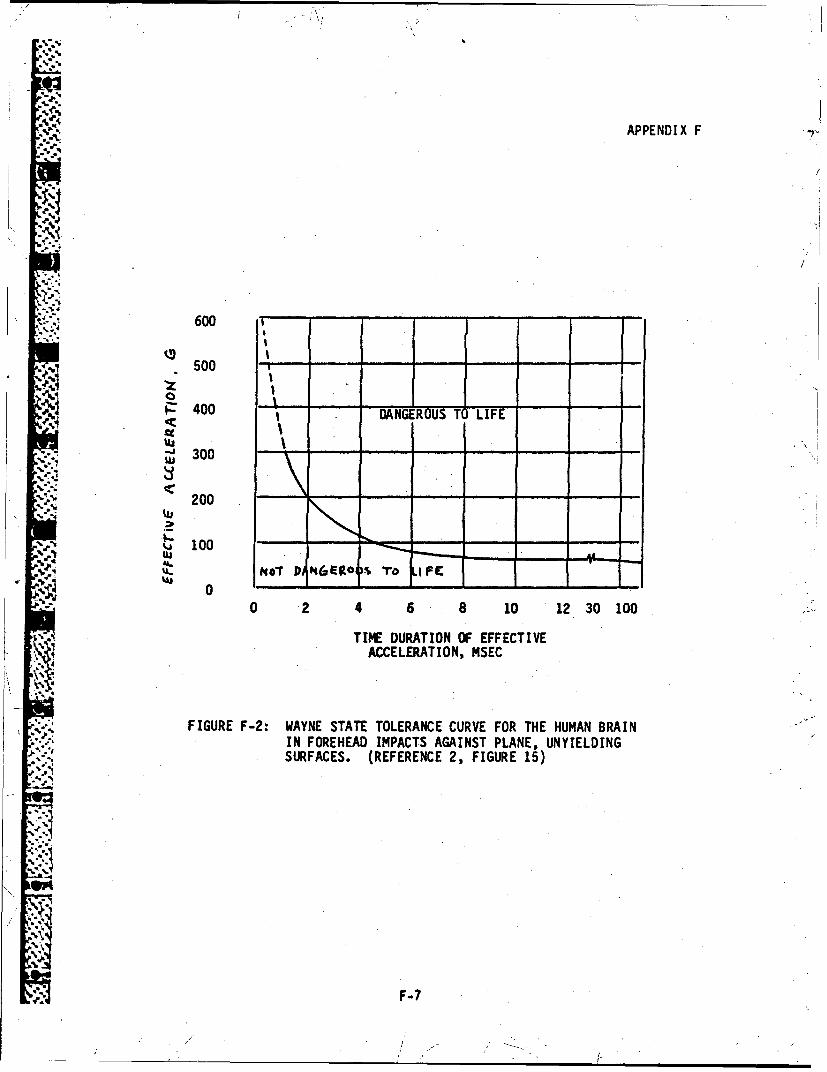
APPENDIX F
600 -
S J I
I5 400
400 DAONGEROUS TO LIFE . .
"j 300\ .--.
200 - -
100 -
l'
,.4T INr Pik6ER " To i
0 2 4 6 8 10 12 30 100
TIME DURATION OF EFFECTIVE
ACCELERATION, MSEC
-: FIGURE F-2: WAYNE STATE TOLERANCE CURVE FOR THE HUMAN BRAIN., '* IN FOREHEAD IMPACTS AGAINST PLANE, UNYIELDING- SURFACES. (REFERENCE 2, FIGURE 15)
F-7

APPENDIX F
The exponent n is a number greater than one, and when taken at 2.5
~ Iresults in an injury criterion whereby an SI of 1000 gives the upperbound of survival and 700 predicts moderate injury. It is readily
apparent that the severity index cannot be applied for long-duration
* acceleration histories, since it would indicate injury from very low
L 2 levels of acceleration; e.g., fatality from 1000 sec at 1g.
The Head Injury Criterion (HIC) of Federal Motor Vehicle Safety Standard
208 is related to the SI but is somewhat more complicated in application.
ti
where t 1 and t 2 are any two points (t 2 > t1) in the acceleration
history.
I. *-.~Head injury is probably of particular concern in impact studies of
transport aircraft where passengers are restrained only by lap belts, andrespond to airplane longitudinal deceleration by rotating the upper body
about the restraint, impacting into facing seat backs. Application ofhead impact injury criteria would require use of an occupant responsemodel to predict the skull-seatback impact velocity, as well as carefullyconstructed data base relating impact velocity to acceleration pulsesexperience in the head impact ev/ent. This data base would probably beobtained experimentally.
F-8

APPENDIX F
4.0 Leg Injury Criteria
For the same reasons discussed above, transport impact study demands a
criterion for tolerance of the lower leg to impact. Snyder's compre-hensive survey* states that 'only four studies are known and all are
unpublished. Here also, the impact criterion would probably require
occupant response dynamic analysis in order to define impact velocities
and associated acceleration pulses..
411
-4F-9

APPENDIX F
"- 5.0 Off-Axis Acceleration
There has been little if any study of injury tolerance in situations where
the body acceleration vector does not lie along one of the principal
(x, y, z) body axes, i.e., where the-"G vector" has components Gx, Gy,G z of which more than one is nonzero. The "natural" engineering
approach would be a criterion based on vectorial combination of the
relative injury measures in each direction:
E ( + 1/2
The Air Force uses this criterion for ejection seat design, but modifies
it in cases where iz s positive (spinal compression) by replacing the
z-component by the Dynamic Response Index:
+ +
(MIL-S-9479B, USAF). For the limit values the specification is
18itf JGz /GL (tn5
16 otherwi e
'.' and the values GxL, GyL, GzL depend upon their durations (FigureTheF-3 shows the relation for GxL)t
iThis criterion has the advantage of simplicity of application but derives-from an arbitrary means of combining the effects of orthogonal components
Sof the nonorthogonal acceleration vector, which lacks experimental
F verioficatlon.
F-10S . .. . . . . . . .. . . . . . . . . . .. . . . . . . . . .
/• •

A0PENDIX F
ZONE I O
ZON ZNE OF PODUEISAI.IlllE-,, -O -
0 S ...
II.I O I1.0 1I.0 3.O /005 TINE AT PLATIAU M6T SECONDS)
A ( -SIO 041 .014 .13 . 13 .I 1 .21 Im .32 t ..31 [.45 [.2 1.I . 13 I I i 11.22 1.sjI.$ I2 1.431 I
I 3S 34 3 2 31 30 21 25 2? 2 5 14 .3 2 21 It II I t I I I INS
REFERENCE NIL 9479B (USAF)
4.'
FIGURE F-3: ACCELERATION LIMIT (+GXL) (RISE TIME ) .03 SEC)
F-11
. -. .....~... ~* * *9 ~*,* * . /

APPENDIX F
6.0 Shock Spectra
In 1967, Fitzgibbon and Vollmer* proposed a method for measuring the
severity of an impact acceleration transient, which is based on responsespectra. .The proposed severity index is. the ratio of two functions:(1) the "shock spectrum" of the particular acceleration history and (2) a
"*"human tolerance" curve of acceleration versus frequency. The human
tolerance curves (Figure F-4) were derived from then-existing criteria
for acceleration vs pulse duration. the shock spectra of a particular
acceleration history is the graph versus frequency of the maximum
acceleration response of a single degree of freedom system with that
natural frequency (and prescribed damping ratio), when SLbjected to the
input acceleration transient in question. Thus the ratio of these two
spectra, itself a function of frequency,, is a measure of the degree of
"injury potential" in a particular impact pulse.
The shock spectra approach provides a means of making organized sense outof impact records, and would be of use in the development of design
criteria for seats and other components. Because of its limitation tolinear systems it seems to have been ignored in application to structures
Aexperiencing large deformation. But the idea of using a "severity index"
which is the ratio of outpu .t acceleration spectrum (calculated in a
simulation code or measured in an impaq it test) to an established "human
tolerance spectrum" remains a viable and attractive approach.
D. D. Fitzgibbon and R. P. Vollmer, "Crash Loads Environment Study", FAA
contract FA 66 WA-i5il, Report DS-67-2 (1967).
F-i12

APPENDIX F
*oer I ur
40
kwetino Iasnryg
44
severityv Huma 3smur
&L -AW
-sa" Mine I"u~
S~wre Zajeawy
FIUE -:SUEPOIIN FSHC PETA N UMNTOEACET OTI
SEERT INEX(RFEENE ,IGRE8
5-I S.L F-13

APPENDIX F
7.0 Flailing Distance and Volume Reduction
An indicator of the possibility of impact of the occupant with hardstructure in his vicinity is the surface defined by all the points whichhis extremities could reach. Thus a design concern is whether hard
structure may be found within that surface. This can be decided withoutsimulating impact dynamics.
An occupant response code will have the position of the occupant in an
accident, and will indicate contacts which he makes. The computation of
the contact forces on impact does not seem to be within the capacity of
present-day occupant response programs.
When the occupant is surrounded by a defined structural surface:, sutch as
* ~a cockpit, the reduction of its volume in an accident is another? crualita-
tive indicator of injury potential. Clearly a drastic volume reduction-- - iiindicates certainty of injury, but there does not appear to be any
quantitative means of generally correlating volume reduction and injurypotential.
1F-1
-N -7!

b NI,
Li
Liz
SI7NCRflMTN(, flIPACT G
FIGURE F-5: IMPACT G TOLERANCE AS A FUNCTION OF AGE
F-15
Z -::2,

i. Repor DOT/FAA/CT-82-70 2. Goviernment Accession No. 3. Recipient's Catalog No.
'V Z NASA CR- 165CF0 I 4k"/ V 6c1c 1 3 T tDa4. Title .nd ,ubtit;e . Report D 1t98March, 1982
Transport Aircraft Accident Dynamics 6. Performing Organization Cnde
7. Author() 8. Performing Organization Report No.
A. Cominsky10. Work Unit No.
. 9. Performing Organization Name and Address
McDonnell Douglas Corporation 11. Contract or Grant No.
Douglas Aircraft Company NAS1-i6111Long Beach, California 90846 13. Toypof Report and PFeriod Covered
Sqonsori gency Nant and Addr I-nal Kegort.,waioniksanw e. Mar., 198alon ram~eronautics andelpace Administration Feb., 19 82
Langley Research Center 14. Sponsing Agenic Cade
Hampton, Virginia 23665
15. Suppltmentary Notes
Technical Monitor, Or. Robert G. Thompson
0 6. Abstract
study was carried t,..t of 112 impact survivable jet transport aircraft accidents(world wide) of 27,400 kg (60,000 lb.) aircraft and up extending over the last 20years. This study centered on the effect of impact and the follow-on events onaircraft structures and was confined to the approach, landing and takeoff segments ofthe flignt.The significant characteristics, frequency of occurance and the effect on the occupantsof the above data base were studied and categorized with a view to establishing typicalimpact scenarios for use as a basis of verifying the effectiveness of potential safetyconcepts.Studies were also carried out of related subjects such as -
Assessment of advanced materials.Human tolerance to impact#Merit functions for safety concepts, ~nImpact analysis and test methods.
17. Key Words (Suggested by Author(s)) 18. Oistribution StatementCasualties, Safety Concepts, ConceptCost and Benefit Parameters.
in
q 19. Security Ciamuf. (of this report) 20. Secur;ty Cla$if. (of this page) 21. No. of page 22. Prim
Unclassified Unclassified 177
For e by the National Technical Information Service. Springfield, Virginia 22161
% A" _ i"