~iet · security classification of thnis page ~iet date enutered) report docmentation page read...
TRANSCRIPT

SECURITY CLASSIFICATION OF THNIS PAGE ~Iet Date Enutered)
READ INSTRUCTIONSREPORT DOCMENTATION PAGE BEFORE COMPLETING FORM1. REPOR11T NUMBER - ,Z GOVT ACCESSION NO.~ 3. RECIPICNY'S CATALOG N4UMSER
NRL Memorandum Report 5026 /4 D f/ / .2A'T4. TITLE (And S..btiff.) jS. TYPE OF REPORT & PERIOD COVERED
Interim report on a continuingIONIINGPOTETIA WAVS I PREONIED GSES problem
IONIINGPOTETIA WAES I PRIONZED ASE 6.PERORMING ORG. REPORT NUMBER
7. AUTNORai. S ONTRACT OR1 GRANT NJUMBER(.)
R. F. Fernslerc
0. PERFORMING ORGANIZATION NAME AND ADDRESS 10. PROGRAM ELEMENT. PROJECT-. TASK-AREA 6 WORK~ UNIT NUMBERS
61 153N: RROI 1-09-41;Naval Research Laboratory 47-0871-O-2* and
*Washington, DC 20375 162707E:.O.Ok4OAA11. CONTROLLING OFFICE NAME AND ADDRESS 12. EPORT DATE
Office of Naval Research Arlington, VA 2.2217Mac 14, 1983
Defense Advanced Research Projects Agency 13. 4"m BER OF PAGES
Arlngon V 22209 ATTN: Program Management/MIS 1 26 __34. MNITORNG AENCY AME AAOORSS(If Il.,.n Irc, Controlling Ollie*) IS. SECURITY CLAS.(ftt eet
UNCLASSIFIED1S. OECL.ASS) FICATION/ODOWNGRAING
16. DISTRIOUTION STATEMENT (of this Report)
Approved for public release, distribution unlimited.
17. DISTRIBUTION STATEMENT (of the abstract entered in Black 20. if dfff.rw~t from. RePort)
IS. SUPPLEMENTARY NOTES
Research supported by the Office of Naval Research and by the Defense Advanced ResearchProjects Agency (DoD) ARPA Order No. 4395 monitored by the Naval Surface Weapons Centerunder Contract N609-21-2-WR-W0066.*Permanent address: JAYCOR - Alexandria- VA
ft. KCEY WORDS (ContIeme a ott ee'. side It flecoma5 A"d Ide"Iti by block numbw)
Ionizing potential waveElectric breakdownAtmospherePre-ionized
k 20. ABSTRACT (ConEflnto an reverse aide JiInceary And Identily by block miber)
* A theory is presented to describe the advance of ionizing potential waves in prejionized gases innonuniform fields. The theory is based on the use of similarity and related arguments to bypasscomplicated mathematics and derive scaling relationships for wave speed as a function of appliedpotential and degree of ionization. For uniform prejonization wave speed is predicted to scalelinearly with applied potential and weaker than linearly with degree of preionization. These pre-dictions are shown to agree well with recent potential-wave measurements obtained in electrical
(Continued)
DD 1473 coyoiTO Oir 1 Nov so is OBsOLETEaS~N 012-014 5401SECURITY CLASSIFICATION OF THIS PAGE (M~en Dec. Enfore)f
A

SECURITY CLASSIFICATIOOPTS AE(,*Oa.£..J
20. ABSTRACT (Coflhinuod)
-dshre studies using lasers to preionize meter-long paths in atmospheric air. Modifications due toradially confined prejonhzation, particle drift, and electrode and other effects are also discussed.
119CURITY CLASSIFICATION OF THIS PAGtgft~ Dwe aae...a
Ed=i

CONTENTS
1. INTRO D UCTIO N ................................................................................................................ I
2. A SIM PLE SC ALING M O D EL ............................................................................................. 3
3. W A VE EQ UATIO NS ............................................................................................................. 3
4. TRA NSM ISSIO N-LIN E M O D EL .......................................................................................... 5
5. RA D IA LLY BO U N D ED IPW s ............................................................................................. II
6. EXTENSIO N TO or, - 0 ....................................................................................................... 12
7. A D D ITIO N AL LIM ITATIO NS AN D M O D IFICATIO NS .................................................... 12
8. DISCUSSION AND COMPARISON WITH EXPERIMENT ................................................ 13
9. CO NCLUSIO N ....................................................................................................................... 14
10. ACKNOW LEDG M ENTS ....................................................................................................... 16
11. REFERENCES ....................................................................................................................... 16
* 5,
I- .. t

IONIZING POTENTIAL WAVES IN
PREIONIZED GASES
1. INTRODUCTION
As is well known, the application of a high potential across a pair of electrodes embedded in aweakly ionized gas causes waves of ionization to traverse the gas. Ionization occurs primarily at theadvancing wave head where a high electric field heats existing electrons to temperatures sufficient forelectron-impact ionization. Impact ionization rapidly raises the electron density, which is termed anelectron avalanche, until the resulting wave conductivity becomes so large that space charge nullifiesthe local electric field. The wave thus converts field energy immediately ahead of the wave into gasionization and excitation energy within the wave body.
The advance of a wave is governed by the interplay between the local electric field E and the waveconductivity or. E determines the growth of a due to electron-impact ionization while (r determinesthe evolution of E via Maxwell's equations. An important parameter affecting wave propagation is theinitial conductivity, o-,, which exists immediately ahead of the wave. A number of mechanisms havebeen proposed for generating this conductivity in gases that are initially un-ionized. Among thesemechanisms are: electron drift,1-4 electron pressure, 5 electron runaway, ' 7 gas photoionization. 8
- 3 andthe photoelectric effect.'" The proponents of these different mechanisms all claim agreement withexperiment, dependin~g upon the interpretation of the experimental results. 1
,16
In this paper we circumvent the controversy regarding the generation of ar, by considering waveswhich propagate in preionized gases- here o, is specified as an initial condition. Such an analysis appliesto all but the first ionizing wave propagating through a gas. The extension to propagation in un-ionizedgases is also discussed.
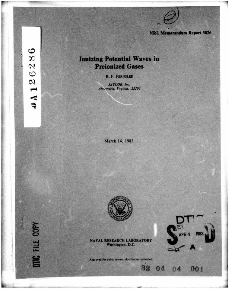
We restrict the problem to nonuniform fields as illustrated in Fig. 1. At time zero an impulse vol-tage, 6,0, is applied to a sharply contoured electrode. This voltage causes an ionizing potential wave(IPW) to emerge and propagate toward a distant ground. The fields far ahead of the wave are negligi-bly small. Our objective is to determine the propagation velocity, , of the IPW as a function of 60 and0',.
Previous investigators have concentrated on determining the dependence of V on the initial elec-tron density, n,, which is directly related to a',. Cravath and Loeb" predicted a weak logarithmicdependence on h,.. Schonland' 8 predicted thLt V scales as ne,' 3. Suzuki'9 claimed, with some experi-mental justification, that V scales as n1,/2. None of these theories indicates the dependence of V onelectrode potential, 00. Furthermore, all of the solutions presented for V depend upon one or moreun- known variables. These variables, which include the wavefront thickness and the electronavalanche rate, may themselves depend upon ne, [see also the criticisms of Winn ' and Uman2 tl].
The present paper attempts to remedy these shortcomings. Two objectives have been imposed onthis attempt. The first is to obtain solutions which depend only on externally specified variables such as60 and a,. Explicit dependence on the "lectron avalanche rate, for example, is considered unacceptablebecause this parameter can vary by orders of magnitude and a unique value cannot readily be chosen.The second objective is to emphasize the physical aspects of the problem, particularly with regard to
Manuscript approved December 16. 1982. I - - ~ ~ -----
>1
HH 4
HH
-
0~
I'
2

obtaining scalitig relationships. As a result. several solutions are actually presented. The first solutionis essentially a dimensional argument which minimizes the mathematics. Subsequent solutions indicatelimitations and modifications which arise in certain parameter regimes and applications.
A SIMPLE SCALING MODEL
Consider the basic problem. An electiode is held at constant voltage. 6o. A long filamentaryIPW emanates from the electrode and propagates with velocity V through a homogeneous. we'ikly ion-ized gas of conductivity o-, We assume that V is determined solely by 6o and oi. Dimensional analysisthen demands that
V - go o 4r,/E, (1)
where E,( oi) is a characteristic field strength and go is a numerical constant.
To determine E,(0 0, o',), we note that two principal rates govern the behavior of IPWs: 4iroawhich controls the evolution of field E: and the electron avalanche rate, S, which controls the growth ofconductivity cr. S is principally determined by E and, to a lesser extent, by the degree of ionization andexcitation. For simplicity S is assumed to be a known function of E and a-, where wave conductiviv a-is a measure of degree of ionization.
We can thus identify two characteristic rates: 4r'r, and S(E,. o',). We presume that these tworates are related and set them equal to within a numerical coefficient. g1 :
S(E, o-,) - g, 4 ro,. (2)
This equation determines E, for a given initial conductivity o-,. Equation (1) then determines wavespeed V. Estimates of go, g, are presented later.
To understand the physical origin of these relationships, imagine doubling all physical dimensionsof the IPW shown in Fig. I while simultaneously doubling the electrode voltage (ho i.e.. all characteris-tic lengths 1, become 21, while 60 becomes 260. This doubling redistributes but otherwise does not alterthe local variables such as a-, S. and E (which scales as oI4). Since the characteristic rates are unal-tered while the characteristic lengths double, wave speed V which scales as St also doubles. We thusconclude that V scales linearly with (6 and that E in Eq. (1) is a function only of a-,. The importantpoint is that in the absence of geometrical constraints on !ength scales , the initial conductivity (r,determines the field E, while the applied potential b0 controls the range over which E, is distributed.
Equations (1) and (2) form the foundation of the present theory. What follows is an examinationof more subtle issues. These include: (i) derive a solution based on a closed set of wave equations:(ii) identify and incorporate other wave parameters of interest: and (iii) determine when the model failsor needs modification.
3. WAVE EQUATIONS
We now present a more formal derivation of Eqs. (1) and (2) and assess some of their limita-
tions. We express Maxwell's equations by
E - -V 6(3)
and
Y + 4~r -1- 0(4)
3

where 46 is the electrostatic potential. Ignoring electron aiffusion and ignoring the massive and essen-
tially immobile ions, the wave conductivity is given by
0- - eneJA (5)
where e is the electron charge, ne the electron density, and / the electron mobility. The electron den-sity evolves according to the continuity equation
-, + Y (n u ) - S le (6)
where u is the electron fluid velocity and where the electron avalanche rate S equals the net electronproduction rate due to collisions. In the absence of electron diffusion, t equals the electron drift velo-city.
(7)
Equations (3)-(7) are closed by specifying the avalanche rate S and mobility A in terms of thefield E'. the conductivity o-, and the gas density N. On the time scales of interest we assume that Ndoes not change so that S and 1 are functions only of E and a,:
S S(Eo-) (8)
;x- /(E.o). (9)For a very weakly ionized wave the dependence on or would also vanish, at higher degrees of ioniza-tion, processes such as electron-ion recombination and super-elastic collisions with excited moleculesaffect the electron dynamics, and thus affect the electron transport coefficients.
Equations (3)-(9) plus the appropriate boundary conditions determine the evolution of ionizingpotential waves. To obtain stationary solutions in a wave frame traveling with constant velocity V withrespect to the laboratory (gas) frame, we use the traveling-wave condition,
- - - V. V (10)
to rewrite Eqs. (4) and (5)-(7) as
VY- ( V- V 47E- aE) - 0 (11)
and
(V + .I ol//) = -Sarl. (12)
To obtain scaling relationships. we look for self-similar solutions of the formq(xc, 0),- q,'?Lf) (13)
where q is any variable. q, is a characteristic value, and
- (x - V)iI, (14)
with 1, being a characteristic length. The functions fq(f) are interrelated through the atomic-physicsrelationships (8) and (9) and through a dependence onior, which characterizes the initial state of thegas. The functions do not depend on electrode potential .0. Note that Eqs. (13) and (14) explicitlyincorporate the traveling-wave condition (10).
Using the transformation
4

we reduce Eqs. (3), (11). and (12) to
E, 6W/I,. (16)(1[ 10 Oh --f°I. - -1= o. (17)
and
Sa =-- (18)
where C. is a dimensionless constant and where the characteristic avalanche rate is taken to be
S, = S(E,, a). (19)
Equations (16)-(19) preserve self-similarity provided the terms in square brackets are constant.This is valid provided Eqs. (1) and (2) are satisfied, and provided the electron drift velocity, -JE, isnegligibly small. Since the electrostatic Eq. (3) is justified only when the wave speed is small comparedwith the speed of light, c. we expect Eqs. (1) and (2) to be valid only for
1AE,I < V < c. (20)
The self-similar analysis and Eqs. (1) and (2) become invalid at low wave speeds. This failurearises because the electrons, which are the dynamic particles controlling wave conductivity, are not sta-tionary in the laboratory frame but are drifting with velocity -,E. The impact of this drift can bequalitatively understood by ignoring radial drift and assuming constant axial drift, -MAE, Equations(17)-(19) then require that
S(E,,a,) - g, 4rcr',(l + uE/ V). (21a)
Or equivalently,
S(E,,a,,) - g, 4rr, (21b)go 6o
replacing Eq. (2). The latter equation demonstrates that E, is in general determined by ab0 as well as by(ri. Furthermore, positive waves for which 60 > 0 require a larger Et{ than negative waves for which6fo < 0. According to Eq. (1). positive waves should therefore propagate slower. Indeed. Eq. (21a)rigorously restricts the negative-wave speed to V > I"!Ei, which reflects the fact that a wave cannotpropagate more slowly than its constituent particles. A similar restriction applies to positive waves onlyif S(E,,o,) increases no faster than linearly with E,. 4
This section has provided a formal basis for the IPW velocity solution, V(460 , 0,. presented ear-lier. The range of applicability has also been discussed. The next section takes yet a differentapproach, discusses additional limitations, and provides estimates for the coefficients go, gl, and C.
4. TRANSMISSION-LINE MODEL
To simplify the problem further, we use a transmission-line analysis to approximate Maxwell'sequations. The electric field along the axis of propagation is then given by
E - - (L.I) (22)z at
where the last term allows for inductive corrections. Ohm's law relates the current I to the wave con-ductance Z via
5
I- .E (23)
where I equals a radial integral of wave conductivity. a. Equation (12) yields
_ [ I' + 1.E) ./A] ,- .Z . (24)
where S is a radial average of S.
Charge conservation produces
(C-6) + 0 (25)
where C.(b is the space charge distributed per unit length along the wave. The distributed capacitance
C. and inductance L_ satisfy
(L- C_) - " 2 < c. (26)
We assume for convenience that (L. C.) is constant and use the traveling-wave condition (10) toobtain
E - - (I- V 2L.C.) (27)
I - 'C4 = V E (28)
and
In (1.E) V + -'+E) V Iln C-+ I (29)Y.(I 51- V2L.C,) V -2 V"
Equations (26)-(29) demonstrate that inductive effects serve principally to limit the wave speed to
V < (L.C.) - "I2 < c. (30)
Henceforth we generally ignore inductive effects except to impose constraint (30).
Let us use Eqs. (24) and (29) to describe the qualitative structure of IPWs. Well within the wavethe conductance Z approaches its maximum value. Z., while the field E approaches a low value, E. E,is a maintenance field defined by the condition
S(El., a-f) - 0 (31)
where oYr is the final conductivity attained in the wave body. If ,T . were zero, E," would equal thebreakdown field, Et, for large or.>, E, can be well below Et, due to the ionization and electron heatingprovided by the excited molecules.
Approaching the head of the wave, E and S begin to rise while 1 gradually falls. As S becomeslarge, the fall of X accelerates. As a result, E and S attain peak values. E and S, respectively, at thewave tip. Beyond the tip E and S approach zero. In this region the distributed space charge, C-4. andcapacitance, C.. also approach zero.
The transmission-line equations are incomplete since the wave radius, rb., and the axial depen-dence of C. are unknown. We thus supplement these equations by modeling the IPW as a long.space-charged filament. Electrostatics then dictates that axial variations in the wave head are character-ized by a common length scale,
t E- C:d,/E, (32)
6

where C. and 0, characterize the capacitance and potential, respectively, of the wave head. Typically.Z . - 0.2 in Gaussian units. Note that a common length scale can be imposed only if condition (20) issatisfied. See Appendix A for details.
We express the tip conductance by
= g' or,7rr (33)and set the wave radius to
r g",. (34)
The strong dependence of the avalanche rate S and weak dependence of the mobility 1A on field E sug-gests that g' - I and g" < 1.
Inserting these assumptions into Eqs. (24) and (29) and imposing constraint (20) yieids. as out-lined in Appendix A,
V - g) 6, 41 roE, (35)
and
S(E. a-,) "" S, = g,1 47o-1 (36)
where
go - g'(g'C) 2/4Ct. 3 7 )
and
g, - gdC.. (38)Here the capacitance at the wave tip satisfies C: << C .
Equation (35) is equivalent to Eq. (1) provided the tip potential (b, equals the electrode potential60. This equivalence is justified, to order C= << 1. provided the resistive voltage drop within the wavebody is small. This proviso is also required to justify the assumption of constant velocity V. A generallysufficient condition is that the IPW length satisfies
I << 1,a,- /E, (39)where Imax is the nominal maximum propagation distance. We point out that IPWs can actually pro-pagate, with diminishing velocity, for distances further than 1m, due to the space charge stored in thewave body. This charge and the capacitive structure of IPWs permits propagation for several "RC"times. suggesting that distances up to 31mx may be possible. This feature additionally explains the abil-ity of IPWs to continue propagating even if the electrode voltage is suddenly terminated.2
The transmission-line analysis and electrostatic model have reproduced the original solutionsgiven by Eqs. (1) and (2). We now use these models to estimate the coefficients g, and ?I.
Equation (35) has a simple physical basis. An IPW propagates by transforming conductioncurrent in the wave body into displacement current at the wave tip. This transformation produces highspace-charge fields at the tip which generate high conductivity in the body. Conduction currents arenegligible at the tip only if the electric field rises to its peak value E, in a short distance
I< < V/4oyl 140)
Equation (32) converts this condition into
V >> Ct,4nT,/E,. (41)
7
|4

The strength of this inequality is !iniitcd by the fact that conduction currents dominate inside thewave. Hence, Eqs. (3i), (38), and (41) suggest that
10 C. = 2 (42)
and
gj -= 10. (43P
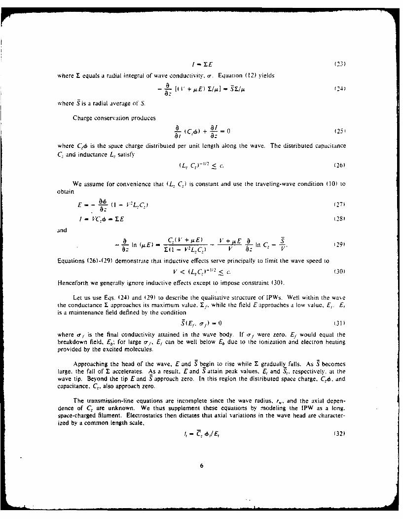
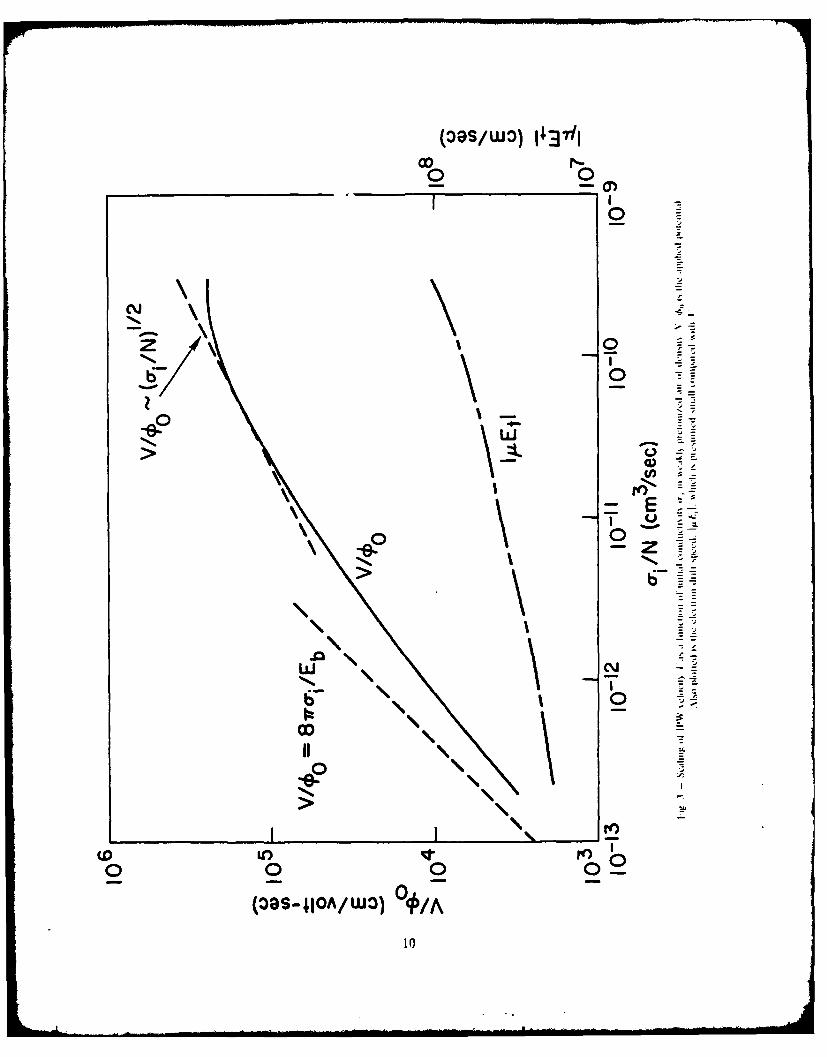
To illustrate these findings, consider very weakly preionized air of density V. The reducedavalanche rate. S/N. is then well known 23 :2 as a function of reduced field. E/N, as shown in Fig. 2. Acorresponding plot of P/(6( as a function of o-,/N is shown in Fig. 3. The latter plot is based on Eqs.11 . 12). (42), and (43). Also plotted in Fig. 3 is the electron drift speed, pAE,. which is presumed
small compared with wave speed V.
Several features of these plots are noteworthy. First, as (7,/N becomes small E, approaches E,where the breakdown strength E/.V --- 100 Td in air. [A Townsend (Td) equals 10-1' Volts-cm- -0.33 Volts/cm-torr.] As a result 1//) scales nearly linearly with -,/,V. This dependence lessens athigh o-,/. At o-,/.V > 10- ') cm3/sec. "/b) is essentially constant. Here S approaches S,,, which isthe maximum possible ionization rate in the gas. In very weakly preionized air, Smx/N - 5 X l0-
cm3/sec.
The restriction on avalanche rate S indicates that relationship (2) is valid only for
(', < amrax =_ Snmax/4,7rgl. (44)
Above this limit conduction currents ahead of the wave redistribute the wave space charge and associ-ated fields before the conductivity can avalanche. We thus conclude that unbounded traveling-wavesolutions cease to exist at high (r,. This failure is closely related to the energy arguments of AppendixB which show that
V/00 < 5 x 104 cm/Volt-sec.
A different failure arises at low o-, where E, approiches E. Here electron attachment generateslarge numbers of negative ions and ion currents which can short-circuit the electron avalanche process.We express the avalanche rate as
S = (a - 17) AE (45)
where agE is the electron-impact ionization rate and "qAE is the net electron-attachment rate: a istermed the first Townsend coefficient and Tj the attachment coefficient. Ion currents can be ignoredprovided the production of negative ions due to electron attachment does not exceed the production ofelectrons. We thus require that the peak avalanche rate satisfies
S, > 71 ( 1)A Et, (46)
and hence that
o', > (T , n- 7(E,)IAEb,/47rg, (47)
where the breakdown field E, is defined by
a(Eb) - -(Eb). (48)
We identify r'mn, as the minimum initial (electron) conductivity required to augment IPW propagation.
8

IF
0-
E
z
10-1
I0-1110 1000 2000 3000
E/N (Td)Fig. 2 - Electron impact ionization rate. .. is ai function of field strength,. E. in veaklv ionized air of density 01 N,
I3S/ O It i
0011-
>0
07
00 02
10

In cold weakly preionized air, -q(Eb)IN- 1.5 x 10-'1 cm2 and E, - 1.5 x 107 cm/sec. Assum-ing g. - 10. conditions (44) and (47) reduce to
10- 14 < < 5 x 10-i1 cm3/sec. (49)
Because o, scales as the degree of preionization, fe,/N, the lower limit is generally more important athigh N while the upper limit is more important at low N.
5. RADIALLY BOUNDED IPWs
In the preceding theory the wave radius r,. was determined by (6o and a-,. We now consider themodifications which arise if r, is externally constrained, either by the presence of walls or by the initialprofile of ar,. We term these waves radially bounded.
Radial constraints have two main effects. The first is that the internal wave structure is altered sothat a single axial length no longer characterizes Z, E. and C. In particular. the distributed capacitanceC. (rather than potential 4&) varies slowly throughout the wave head and may be treated as constant.Setting Cj - C. and evaluating Eqs. (29) and (33) at the peak field E, yields
V - g2 (47 -i S) 1/2 rb (50)
where rh is the bounded-wave radius and
, 9' 1- V2 L_ C92 - -- 1. (51)4c_ I+ AEV
A nearly identical equation was obtained by Suzuki. 19
The second effect is that E, is determined not by the initial conductivity but by
E, - g"C..o1rb, (52)
provided the resistive voltage drop in the wave body is negligible. This equation is a direct extension ofEqs. (32) and (34) and closes the velocity solution of Eq. (50) by defining the peak avalanche rate.
S, - S(E,. a,). (53)
The transition from the unbounded wave solutions, given by Eqs. (1) and (2). to the boundedsolutions, given by Eqs. (50)-(53). occurs when the bounded wave radius rb becomes less than theunbounded radius. This transition typically occurs in air when
bo/rN > 10- 1 Volt-cm2. (54)
The character of radially bounded IPWs differs from that of unbounded IPWs. Bounded IPWs arepredicted to behave as follows: wave speed V scales nearly linearly with o /2 V exhibits a monotonicbut generally nonlinear dependence on 60. V exhibits a nonmonotonic dependence on bounded-waveradius rb and on gas density N. Moreover, constraints (44) and (47) on r%, are no longer valid sinceEq. (2) does not apply. In particular, bounded-wave solutions exist even at high o- >> 0 max. The rea-son is that bounded waves are constrained to be filamentary which is the characteristic required forspace-charge field enhancement; i.e., the absence of conductivity outside rb ensures that space-chargefields and subsequent avalanching will develop inside rb.
11

6. EXTENSION TO', - 0
For many problems of interest the initial conductivity ahead of the wave is well below the value.crm,,. required to influence IPW propagation. Waves can still propagate, however, provided the waveitself can generate the necessary seed ionization at the wave tip.
The only mechanism explicitly incorporated in the theory for generating this seed ionization iselectron drift. Here the directed motion of the electrons due to the local electric field advances thewave. Equation 12Q) indicates that for vanishing tip conductance, wave speed Vlapproaches
V - E,. (55)
This is positive definite only for negative waves where V. E < 0. Electron drift can thus account forslow negative waves but cannot account for fast ( V >> 108 cm/sec) negative waves or for positivewaves.
The theory can easily accommodate other seed ionization mechanisms provided the tip conduc-tivity or conductance can be estimated. The only formal constraint is that condition (47) be satisfied.A less formal constraint is that the seed mechanism account for positive waves as well as negativewaves since the experimental character of both waves is so similar. This last constraint excludes. forexample, the electron-runaway mechanism.'
Two proposed mechanisms in nonuniform fields are gas photoionization' -' 3 and electron pressure. 5
(The photoelectric effect' 4 is presumed irrelevant because the ground electrode is in a weak-field regionfar from the wave.) For positive waves the electron-pressure mechanism requires an anomalouselectron-heating process which so heats electrons in the positive wavefront that the electron fluid velo-city reverses direction and opposes electron drift. Such a reversal is deemed improbable because theseelectrons would then rapidly lose energy to the electric field rather than gain it.
A major criticism of the photoionization mechanism is that the relevant atomic physics is oftenunknown."- 6 Photoionization nonetheless remains promising because: (i) ample experimental evi-dence2' demonstrates that it or a similar process occurs in electrical discharges and. by inference, occursin IPWs: and (ii) inclusion of the experimentally determined photoionization rate in the electron con-tinuity equation directly leads to fast positive and negative waves.12 , 13
To illustrate the role of seed ionization mechanisms on wave propagation, consider gas photoioni-zation. Ionizing photons are created within the wave with an efficiency 8 per electron-impact ionizationevent. The photon-production process determines whether 8 depends on gas density N. field parameterE/N or degree of ionization. Typically, 8 << 1.8 Such a low efficiency means that photoionization isunimportant in the wave head or body.
Photoionization can nonetheless be important ahead of the wave provided the photon-absorptionlength, X,, is much longer than the characteristic electron transport lengths. Photoionization then gen-erates, within a length Xa outside the wave head, an initial conductivity of a', - 8 -,. where a-, is thefinal wave conductivity. This seed ionization is sufficient to sustain wave propagation provided the gainin conductivity, c',/a',, due to electron-impact ionization in the wave head exceeds 8- t. See Ref. 28 forfurther discussion.
7. ADDITIONAL LIMITATIONS AND MODIFICATIONS
Two additional parameters which can affect V and thereby invalidate or modify the theory areelectrode effects and a finite rise-time. r,, of the applied voltage. Only if
7, < < Ima/V 1561
12

can the voltage rise-time be ignored. If this condition is not satisfied, the effective electrode %oltage isreduced and Eq. (1) should be adjusted accordingly. Alternatively if 60 rises linearly with time, wavespeed is ultimately given from Eqs. (10) and (27) by
V'- E71' (I - V'2LC.) (57)
where the asymptotic field strength Er is defined by Eq. (31).
Electrode effects assume a particular importance when examining the differences between positiveand negative waves. Positive waves generate an electron flux that flows into the electrode, whereasnegative waves require an electron flux that emanates from the electrode. Negative waves thus requirean active electron-emitting surface whereas positive waves require an essentially inactive, electron-absorbing surface. Any restriction on electron current flowing in or out of the electrode results in resis-tive sheaths, which reduce the voltage appearing at the wave head and thereby reduce wave speed V.Electrode sheath restrictions are thus usually more severe for negative waves than for positive waves.Such restrictions and differences become unimportant, however, when the applied potential is large(typically. Of) > 10 kV) compared with the sheath potential.
8. DISCUSSION AND COMPARISON WITH EXPERIMENT
Let us briefly review the previous theoretical predictions. We have identified two types of waves:radially bounded and radially unbounded. Unbounded means that the wave radius is smaller than anyexternal constraint. The velocity of unbounded waves is predicted to scale at low a-,/Nas
V - 6o a,/.V - One/N 2 (58)
where N is the gas density and he, is the initial electron density ahead of the wave. By contrast, thevelocity of radially bounded waves is predicted to scale as -1/2 and to depend in a complicated manneron Of), N. and bounded-wave radius rb. At high Of) and low N. r, this dependence simplifies to
V -(, ) r. net rb. (59)
Electrode effects and other processes can easily modify these scalings.
Corresponding to the two types of waves are two classes of experiments: IPWs launched in low-pressure glow discharges where the initial conductivity is determined by the glow-discharge current: andhigh-pressure experiments using lasers to preionize the gas. A third pertinent category is the longspark29 in which a succession of IPWs (streamers, leaders, and return strokes) propagate along the samepath. A difficulty with the latter experiments is that the state of the gas between successive waves isunknown, and hence o-, is indeterminate. We point out that each successive wave encounters an initialconductivity much higher than that experienced by its predecessor. As a result wave speed is higherand wave radius is (slightly) smaller. Successive IPWs are therefore predicted to be radially unboundedprovided the predecessor is (until (-, exceeds a'mix as defined by Eq. (44)).
We focus on a limited subset of the availa' 'e experimental data. Consider first the laser-guideddischarges of Koopman and Saum 30 and of Greig, et al.31.32 These experiments used a pulse of energyfrom a Nd: glass laser or a CO2 laser to preionize meter-long paths in atmospheric air. The subsequentapplication of an impulse voltage across electrodes at each end induced IPWs to propagate within thelaser-formed channel, ultimately leading to a high-current discharge. The initial conductivity was con-trolled by varying either the laser energy or the delay time between firing the laser and applying theimpulse voltage.
13

The minimum laser-generated electron conductivity. 0 min, required to guide IPWs was consistentwith predictions (47) and (49). Analysis of the experiments indicated that thermal detachment ofnegative ions by laser-heated molecules,31' 32 rather than photodetachment by IPW photons, 30 played akey role in determining amin.
The experiments of Greig, et al. attempted to determine the dependence of wave speed V oninitial conductivity o-, and electrode voltage 6. Wave speed was determined by measuring the arrivaltime of the potential wave at several axial positions along the laser-designated path using capacitive vol-tage probes. Results for Vas a function of co are shown in Fig. 4 for an initial conductivity of o',/N --10- 12 cm 3/sec. Not only is the plot linear, but the measured value of V10o - 5 x l03 cm/Volt-secagrees to within experimental uncertainty (a factor of 2 or more for (r,/,V with that predicted by Fig. 3.Such agreement is remarkable considering the order-of-magnitude estimates used for coefficients go andgl. The dependence of Von o-, was less clear due to a large scatter in the conductivity measurements.V was shown, however, to exhibit a strong monotonic dependence on o-,.
Several other features of Greig's experiments are noteworthy. First, optical diagnostics indicatedthat the IPWs were radially unbounded since the wave radius (r,, < 0.1 cm) was smaller than theradius (0.2 to 2 cm) of the laser-formed channels. Second, the guidance afforded by the laser preioni-zation was strong: IPWs could be guided, for example, even along laser paths that were perpendicularto the static electric field lines. This plus the large increase in guided wave speed over unguided wavespeed again supports the prediction that a-, strongly influences wave propagation. Third. wave speedand wave potential decreased with increasing propagation length, I. And fourth, the maximum propaga-tion length for a given electrode potential 60 corresponded to an average electric field (/bd1) of
Emin - 1.5 kV/cm. (60)
This field is roughly one third of the maintenance field, E,. predicted by numerical simulations basedon the detailed air chemistry code, CHMAIR. 3 3 These simulations assumed that laser preheating raisedthe channel temperature from 300'K to 800'K and lowered the gas density accordingly.32 The manyapproximations employed in the simulations preclude an accurate determination of E,. The resultsnonetheless support the earlier contention that Emin could be as low as one third of E, due to the capa-citive structure of IPWs.
We now consider IPWs launched in low-pressure glow discharges where the wave radius is typi-cally restricted to the glow-discharge radius. A review of these and related experiments was given byFowler. 34 We shall concentrate, however, on the more recent experiments of Suzuki.19 The latter workis selected because it specifies all primary parameters of interest. Suzuki additionally presented abounded-wave theory similar to that given here.
Suzuki's results may be summarized as follows: wave speed V" scaled as ne','2: V exhibited amonotonic dependence on 00 which saturated at high 0o: V scaled linearly with 6'r, where 7, is thevoltage rise-time. and positive waves typically propagated faster than negative waves. These findingsagree well with the bounded-wave predictions. This agreement was further confirmed by numericalsimulations which coupled the chemistry code CHMAIR to Eqs. (27) and (29), using constant specifiedwave speed Vand a constant capacitance of C: - 0.2.
9. CONCLUSION
In this paper we have concentrated on the propagation of ionizing waves in preionized gases. Wehave shown that these waves propagate not because of directed-particle motion, but because electron-impact ionization due to the local electric field raises the degree of ionization and hence the conduc-tivity in the wave head. As a result the wave space charge and fields are displaced forward, therebycausing ionization to commence in a new region ahead of the wave. Processes such as electron drift.diffusion, etc. are of secondary or lesser importance.
14

0
LLI >
0 N 0o
(S/W3 600) MU~S 3AVM 1VI1NN.L0d
Ll
15

The crux of the analysis has been the use of similarity and related arguments to by-pass themathematical complexities and arrive at a wave velocity, V(4 0,nz,). The complexities chiefly comprisetwo forms: the two-dimensional elliptic character of Maxwell's equations, a feature which is responsi-ble for space-charge field enhancement and is thus essential for wave propagation in nonuniform fields:and complications due to the functional dependencies of S and / on E, N. and o,. The similarity argu-ment is like that used in simple thermodynamic and hydrodynamic problems. 3 5' 3 6 It is based on the factthat the continuity equation for conductivity a- and Maxwell's equations for field E and potential (b arelinear.
In the simplest nonuniform field problem. we have found that wave speed scales nearly linearlywith the external control parameters a' i and 6o. We have also discussed the influence of constraintssuch as radial boundaries and electrode effects, and have outlined how to extend the analysis to propa-gation in un-ionized gases. Comparison with experiment has generally been favorable. Agreementbetween theory and experiment at a few operating points is insufficient, however, to validate a theory.as evidenced by the wealth of IPW theories and good agreement claimed for all. Of greater use is thedetermination and evaluation of scaling relationships between measurable variables. Until careful meas-urements such as those of Suzuki' 9 have been performed over a wide parameter space. distinctionsbetween differing theories will likely remain unresolved.
10. ACKNOWLEDGMENTS
The author wishes to express his appreciation to Dr. M. Raleigh for a careful reading of themanuscript, to Dr. R. E. Pechacek for patiently explaining the experimental measurements, and to Dr.J. R. Greig for useful discussions and encouragement. This work was supported by the Office of NavalResearch and by the Defense Advanced Research Projects Agency.
11. REFERENCES
1. F. Llewellyn-Jones, loni:arion and Breakdown in Gases (Methuen, London, 1966), p. 50.
2. N.W. Albright and D.A. Tidman, Phys. Fluids 15, 86 (1972).
3. A.L. Ward, Phys. Rev. A138. 1357 (1965).
4. A.I. Davies, C.S. Davies, and C.J. Evans, Proc. lEE 118, 816 (1971).
5. R.G. Fowler, Advances in Electronics and Electron Physics 41. 1 (1976).
6. L.P. Babich and Yu. L. Stankevich. Zh. Tekh. Fiz. 42, 1669 (1972) tSoy. Phys. Tech. Phys. 17,1333 (1973)].
7. E.E. Kunhardt and W.W. Byszewski, Phys. Rev. A21, 2069 (1980).
8. H. Raether, Electron Avalanches and Breakdown in Gases, (Butterworth, London, 1964).
9. J.M. Meek. Phys. Rev. 57, 722 (1940).
10. R. Klingbeil, D.A. Tidman, and R.F. Fernsler. Phys. Fluids 15, 1969 (1972).
11. E.D. Lozansky and O.B. Firsov, J. Phys. D6, 976 (1973).
12. L.E. Kline and J.G. Siambis, Phys. Rev. A5, 794 (1972).
16

13. K. Yoshida and H. Tagashira. J. Phys. D9, 491 (1976).
14. 1. Dutton, S.C. Haydon. and F. Llewellyn-Jones. Proc. Roy. Soc. (London) A218. 206 (1953).
15. F.R. Dickey, J. Appi. Phys. 23, 1336 (1952).
16. E.E. Kunhardt. IEEE Trans. Plasma Sci. 8. 130 (1980).
17. A.M. Cravath and L.B. Loeb, Phys. 6, 125 (1935).
18. B.F.J. Schonland. Proc. Roy. Soc. (London) A164. 132 (1938).
19. T. Suzuki. J. Appi. Phys. 48. 5001 (1977).
20. W.P. Winn, J. Geophys. Res. 70. 3265 (1965).
21. M.A. Uman. Likt'hning (McGraw-Hill. New York. 1969), p. 223.
22. N.S. Rudenko and V.I. Smetanin. Zh. Tekh. Fit. 44, 2602 (1974) [Sov. Phys. Tech. Phys. 19.1616 (1975)].
23. C.R. Rao and G.R.G. Raju. J. Phys. D4. 494 (1971).
24. M.A. Harrison and R. Geballe. Phys. Rev. 91, 1 (1953).
25. H Ryzko. Proc. Phys. Soc. London 85. 1283. 1965.
26. F. L Jewel lyn-Jones. Hand. Phys. 22. pp. 28-47 (1956)i.
27. G.W. Penney and G.T. Hummert. J. Appi. Phys. 41, 572 (1970).
28. L.B. Loeb. Hand. Phys. 22. p. 488 (1956).
29. G.N. Aleksandrov. B.N. Gorin. V.P. Redkov. 1.S. Stekol'nikov. and A.V. Shkile%. Dokl. Akid.Nauk SSSR 183, 1048 (1968) [Sov. Phys.-Dokl. 13. 1246 (1969)).
30. D.W. Koopnian and K.A. Saum, J. App!, Phys. 44, 5328 (1973).
31. J.R. Greig. D.W. Koopman. R.F. Fernsler. R.E. Pechacek. LI. Vitkovitsky, and A.W. Ali. Phys.Rev. Lett. 41, 174 (1978).
32. R. Fernsler. J.R. Greig, J. Halle, R. Pechacek. M. Raleigh. and I.M. Vitkovitsky. AIAA-80-1380(1980). Also. R. E. Pechacek (private communication. Fig. 4).
33. R.F. Fernsfer, A.W. Ali. J.R. Greig. and I.M. Vitkovitsky. Bull. Amer. Phys. Soc. 23. 775 (1978)(Naval Research Laboratory MR41 10 (1979)].
34. R.G. Fowler, Advances in Electronics and Electron Physics 35, 1 (1974).
35. G.K. Batchelor, An Introduction to Fluid Dyvnamics (Cambridge University Press, Cambridge,1967), p. 188.
17

36. Ya. B. Zel'davich and Yu. P. Raizer. Physics of Shock Waves and High- Temperature HydrodynamicPhenomena. Vol. i (Academic, New York, 1966), pp. 93-95.
37. A. Haberstich, thesis, University of Maryland, 1964.
38. W.P. Winn, J. Appl. Phys. 38. 783 (1967).

Appendix A
CHARACTERISTIC LENGTH SCALES
Consider the following length scales which are to be evaluated at the peak field. E,:O V'
/- In E (Al)
1 1 r C (A2),- -inc=
1 In (C4) (A3)!0: I - t A
02
1 -, In ,AAS)
where by definition
E -0. ,A6)
We employ the reasonable assumption that the mobility / and avalanche rate S also attain peak 'aluesat Er. Hence, at E,
0( (, A (A7)
and
I In (1l )l - . (A8M
Evaluating Eqs. (24) and (28) at E, then yields
V + 4;- u s, 11 (A9)
I.- EE,/ , ,, (AI)
Substituting these results into Eq. (29) evaluated at E, produces
I I I (A I)
where
- (I - V2L.C:). (AI2)
Similar manipulations performed on the first derivatives of Eqs. (24), (28), and (29) lead to
- I (A13)
19

and
n 1 +LEiJIJ-; I " "" (A14)
The dependence of the length scales /, on wave speed V in Eqs. (Al )-(A14) vanishes in the limit
i 1AE,I < < V < < (LC.)- /" 2 . (AI)
Hence, by imposing this constraint we can neglect wave motion and simply consider the electrostaticproblem.
For a filamentary wave in which the radius r,, and body length I satisfyr,. < I-,< </I. (AI16)
as is implicitly assumed in the transmission-line equations, Gauss's law dictates that the electrostaticfield near the tip of the wave is determined by the distribution of space charge in the wave head. Sincethe mobility A is not a strong function of field E, we thus expect that
15 -.- 13 -.- It 1.A 17)
where
4,- c.-,/E. (A18)
Here C:, characterizes the space charge in the wave head, and E, is the peak field at the tip. In theabsence of coaxial ground returns, the distributed capacitance is given in Gaussian units b%
'- [2 In (2/ 3/r,.)1 - ' (AI19)
and typically satisfies
C. -- 0.2. (A20)
Combining Eqs. (Al I)-(AIS) with Eqs. (A17). (A18), and (A20) produces the desired result that
,- < It, (A21)
for i - 1. 5.
We use result (A21) as follows. Eliminating wave speed V from Eqs. (A9) and (AI0) produces.to order i E! t,
- , t QL (A22C.,,, , c:, 42.
Substituting Eqs. (33) and (34) into Eqs. (A9) and (A22) then leads directly to the solution for wa~espeed, V(,i,, (Y,). as expressed by Eqs. (35) and (38).
20

Appendix BENERGY CONSERVATION
Previous investigators3 7, 8 have attempted to derive scaling relationships using energy conserva-tion. We note here a potential fallacy in such an approach, show how to avoid it, and derive an upperlimit for the wave velocity that is more general and yet consistent with the results presented earlier.
The power supplied by the electrode goes into field energy and gas dynamics according to
J11 '(-L- C,:2 + L:1,2 + E(BI
where E, is the energy absorbed per unit length by the gas and where the electrode current
, = 1," C j. CB2)
These equations reduce to
, C 4 ,(1 - "LC.). (B3)
Note that e, - 0 as V - (L.C)- l 2: i.e.. all the energy is stored in the electromagnetic fields.
A certain fraction ./ of the absorbed energy e, goes into ionization, which suggests that the final
wave conductance is given by
1, = f eli, E W (B4)
where IV is the gas ionization energy. The wave velocity can be expressed according to Eq. (28) by
V = E, 1,.C-4,. (B)
Hence,
I . 6 -- ,Ej (I - L C .). (Bb )
The usefulness of Eq. (B6) depends upon the ability to estimate ./, As we now show, the assump-tion of constant fis often invalid.
Integrating the electron continuity Eq. (24) from the electrode to the wave tip yields
, V , E, d f _ (B7)
where we have ignored the initial conductance. 1,, in comparison with E,. To relate this to the energyabsorbed by the gas, we note that the wave absorbs energy in the electron drift frame at a rate L E2 .Transforming to the lab frame. the wave absorbs energy at a rate
S E2 )Va-' E -,+---'- (BS)
where the final energy absorbed is given by
f f 1E 2 (B9)E, -f di d + E'
21

\Nk may thus rewrite Eq. (B7) as
Mhere the average value of a variable x is defined by
<X> f '/1 ( '+, E -v- (BI I
Note that terms in parentheses are - I.
Comparison of Eqs. (B4) and (BO) leads to
= <S (B12)
e;A E 2
% hich re-expresses energy conservation. Wave velocity is thus given by
- E,,,b < - > i1 - V2L C. (13)
I) estimate fwe rewrite Eq. (B12) in terms of the Townsend coefficients a and "1:
f=< w_._ W> . (1314)eE
Figure 5 shows a plot of the fraction
S"= w (1315)eE
for weakly ionized air. This plot assumes an effective ionization energy of W = 15 eV, which equals thesum of the ionization potential plus the average kinetic energy of the plasma electrons. The strongdependence of ." on field parameter E/. demonstrates the fallacy of assuming constant f
Equation (B6) can be used to provide an upper limit for wave speed I by noting that the ioniza-tion fraction
. < 1. (BI6)
Using typical values for the downstream drift speed.
u, E, < 10 cm/sec, (B17)
and for the ionization energy,
W > 10 eV. (BIS)
thus suggests that
V/6 < 5 x 10- cm/Volt-sec (B19)
irrespective of initial conditions, gas density, or wave propagation mechanism. This condition can beviolated only if the average applied field appreciably exceeds the maintenance field E, or if the poten-tial wave is nonionizing.
22

0
00i.
23o