search.jsp?r=19650018856 2020-03-24t05:02:26+00:00z
TRANSCRIPT

< f
(NASA C R OR TUX O R AD NUUBLRJ
https://ntrs.nasa.gov/search.jsp?R=19650018856 2020-03-24T05:02:26+00:00Z
8 Y w
W
FJATIONAL AERONAUTICS AND SPACE A I M I N I S W O N
mcmcAL mo€wxDuM x-95
PERFORMANCE O F A COMPOSITE SOLID PROPELGANT
AT S m HIGH ALTITUDES*
By Carl C. Ciepluch
SUMMARY
An invest igat ion w a s conducted i n an a l t i t u d e test chamber t o deter- mine the performance of a t y p i c a l composite s o l i d propellant at high noz- z l e pressure r a t i o s and for a range of chamber pressure. measurements were made over a range of pressure r a t i o from 115 t o 1200 f o r f u l l y expanded flow. impulse w e r e determined f o r a range of chamber-pressure from 180 t o 920 pounds per square inch absolute. spec i f ic impulse and charac te r i s t ic exhaust veloci ty were compared with t h e o r e t i c a l l y calculated values f o r both frozen and equilibrium expans ions.
Specific-impulse
The charac te r i s t ic exhaust veloci ty and s p e c i f i c
Ekperimental measurements of propellant
/ For a reduction i n operating chamber pressure from 920 t o 180 pounds
per square inch absolute, the charac te r i s t ic exhaust-velocity eff ic iency based on equilibrium flow decreased 2.5 percentage points from 98 t o 95.5 percent. For the same reduction i n operating chamber pressure, the i m - pulse e f f ic iency decreased only about 1 point. Over a range of nozzle pressure r a t i o from 115 t o 1200, the measured s p e c i f i c impulse averaged 7 percent lower than the theore t ica l value f o r equilibrium flow. About 4 percent of the 7 percent loss i n specif ic impulse could be accounted f o r by considering combustion 3nd nozzle inef f ic ienc ies . The remainder of the loss w a s apparently a r e s u l t of frozen expansion in the nozzle.
INTRODUCTION
The propulsive charac te r i s t ics of s o l i d propel lants t h a t are neces- s a r y f o r ca lcu la t ion of missi le or vehicle requirements can readi ly be ob- ta ined f o r moderate pressure r a t i o s i n sea- level s tud ies . However, f o r high-performance stages, which operate at l o w chamber pressures ( for r e - duction of case weight) and high a l t i tudes , extreme extrapolation of sea- l e v e l performance t o higher pressure r a t i o s i s required. formance calculat ions can be used as a guide f o r t h i s extrapolation; how- ever, these calculat ions depend on the accuracy of t h e thermodynamic data
Theoretical per-
T i t l e , Unclassified. *
. ... e. 0 . 0 . .
Ammonium perchlorate (oxidizer) a
Polyvinyl chloride (binder)
Dibutylsebacate { p l a s t i c i z e r )
Carbon black
S t a b i l l z e r and v iscos i ty depressant
2
81.03
8.44
9.90
.05
.58
involved. Furthermore, the impulse loss due t o nonequilibrium flow i s d i f f i c u l t t o pred ic t . 'Therefore, having experimental methods of deter- mining the performance of sol id-propel lant rocket engines a t high expan- s ion r a t i o s and low chamber pressures would be advantageous. An experi- mental invest igat ion w a s therefore conducted i n the Lewis a l t i t u d e wind tunnel t o determine the performance of a t y p i c a l composite s o l i d propel- l a n t a t high nozzle pressure r a t i o s and low chamber pressures. The e f - f e c t of chamber pressure on c h a r a c t e r i s t i c exhaust veloci ty o r combustion temperature f o r the propellant invest igated w a s a l s o determined.
The performance da ta include the s p e c i f i c impulse for nozzle pres- sure r a t i o s up t o 1200 (equivalent area r a t i o , 65) and the e f f e c t of chamber pressure on charac te r i s t ic exhaust ve loc i ty and s p e c i f i c impulse. Theoretically calculated performance w a s determined f o r the range of v a r i - ables invest igated experimentally.
APPARATUS AND PROCEDURE
Prop e l l a n t
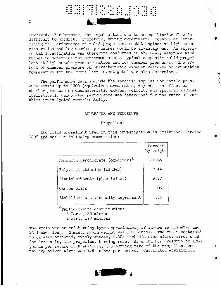
The s o l i d propellant used i n t h i s invest igat ion i s designated "Arcite 368" and has the following composition:
Percent by weight
%ar t i c l e - s i z e d i s t r i b u t ion : 2 Par t s , 30 microns 1 P a r t , 170 microns
The grain w a s an end-burning type approximately 1 2 inches i n diameter and 2 0 inches long. Nominal grain weight w a s 1 2 0 pounds. The grain contained 55 axial ly oriented, evenly spaced, 0.005-inch-diameter s i l v e r wires used f o r increasing t h e propellant burning r a t e . A t a chamber pressure of 1000 pounds per square inch absolute, the burning r a t e of the propellant con- ta ining s i l v e r wires w a s 2.6 inches per second. Calculated equilibrium
\
I
v
I u C cf
r,
U
I

cn 0 m w I
Average chamber
pressure, %,a,
lb/sq in. abs
9 20 9 20 9 20 920 920 333 180
/
Nozzle ambient pres sure,
lb/sq in. abs PO'
0.8 1.2 2.0 3.2 8.0 3.2 2.0
I
Nozzle axea r a t i o ,
AeIIL,
8
Nozzle t h r o a t area,
sq in . At,
3
cortbustion tenpera twe of the propellant is 5122O R at loo0 pounds per square inch, and the calculated equilibrium s p e c i f i c impulse f o r expan- s ion from lo00 pounds per square inch absolute t o sea- level pressure i s approximately 240.
I n s t a l l a t i o n
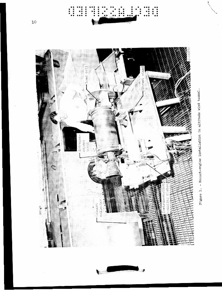
The rocket engine (fig. 1) w a s installed i n t h e a l t i tude wind tun- nel , which provided control of t h e ambient pressure. mounted on a t h r u s t s tand that ercployed t h e f lexure-plate pr inc ip le f o r t h r u s t measurement. i g n i t e d hydrogen-oxygen torch. A conical nozzle w i t h a 45' convergent half-angle and a 15O divergent half-angle w a s used. The nozzle-throat contour w a s an a rc , the radius of which w a s equal t o the diameter of the nozzle t h r o a t . The nozzle w a s uncooled and w a s constructed with heavy w a l l s t h a t were insulated in te rna l ly with a "flame-sprayed" coating of zirconium oxide. s ion during t h e rocket f i r i n g s .
The engine w a s
The propellant w a s i g n i t e d by means of a spark-
A
2 P
There w a s essent ia l ly no t h r o a t enlargement due t o ero-
4
$ - A l l var iab les were measured with t rans ien t instrumentation. These included t h r u s t , chamber pressure, nozzle-wall s t a t i c pressure, and am- b i e n t pressure. recording oscil lograph. The estimated accuracy with which t h e chamber- pressure and t h r u s t measurements could be made was : The weight of grain and i n h i b i t o r burned during each f i r i n g could be measured t o t h e nearest 1/4 of 1 percent. Chamber-pressure s t a t i c t a p s w e r e lo- cated i n a region of low enough Mach number so t h a t they measured t o t a l chamber pressure. Tubing lengths t o chamber-pressure pickups were kept t o 6 inches or less i n order t o ensure adequate frequency response.
Transient measurements w e r e recorded on a d i r e c t -
4 2 percent.
v
The data were taken at the following conditions:
65 .O 47.7 32.4 22.8 11.4 11.4 11.4
2.39 2.39 2.39 2.39 2.39 4.37 5.74

4
a. *.a a a * . a a. a. a a a * a * a. a . a . a . a * * a . a * * a * a . a * * * a . a a a . a a * a * *
*a: a*: :b: :-Iaa* * a : *a:
. *. bi. *<
The tunnel ambient pressure w a s adjusted f o r each f i r i n g t o expand ap- proximately f u l l y t he exhaust gases f o r each combination of a rea r a t i o and chamber pressure invest igated. However, t he nozzle-exit pressure w a s usual ly s l i g h t l y d i f f e r e n t from the ambient pressure. w a s adjusted t o represent f u l l y expanded flow by subt rac t ing the Ae(p, - pg) term from the measured t h r u s t . appendix A,) determined b y weighing the propel lant and inh ib i to r before and after each f i r i n g . t e r i s t i c exhaust ve loc i ty e* were made f o r each run. The details of t he calculat ion procedure a re discussed i n appendix B.
The t o t a l impulse
( A l l symbols a re defined i n The weight of the propel lant burned during the f i r i n g w a s
Calculations of average values of spec i f i c impulse and charac-
RESULTS AND DISCUSSION
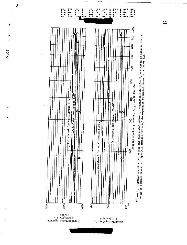
Effect of Chamber Pressure on Charac te r i s t ic
Velocity and Spec i f ic Impulse
The e f f e c t of chamber pressure on the c h a r a c t e r i s t i c exhaust veloc- i t y e* of the propel lant i s shown i n f igu re 2 ( a ) . A s l i g h t reduct ion i n e* e f f ic iency (c*/c&), a r e s u l t of combustion ineff ic iency, i s noted as t h e chamber pressure i s reduced. pressure from 920 t o 180 pounds per square inch absolute, e* e f f ic iency based on equilibrium flow decreased approximately 2.5 points from 98 t o 95.5 percent. Since t h e combustion temperature i s approximately propor- t i o n a l t o t he square of e*, combustion-chamber temperatures correspond- ing t o chamber pressures of 920 and 180 pounds per square inch absolute would be 96 and 9 1 percent of t he t h e o r e t i c a l equilibrium value, respect ively.
For a reduction i n chamber
Since the spec i f i c impulse of a propel lant v a r i e s approximately d i - r e c t l y with e*, the observed reduction i n e* e f f ic iency as chamber pressure w a s reduced should produce approximately the same reduct ion i n spec i f ic impulse e f f ic iency ( I / I t h ) at equivalent nozzle pressure r a t i o s . However, as indicated i n f igu re Z(b), a reduct ion of only about 1 per- centage poin t w a s obtained. There are two possible e f f e c t s t h a t could compensate the expected reduction i n s p e c i f i c impulse due t o decreased measured values of e* at low chamber pressures . One explanation i s t h a t combustion ine f f i c i enc ie s i n the chamber reduced experimental c* values, b u t some t h r u s t w a s recovered because of combustion i n t h e nozzle. A second p o s s i b i l i t y i s tha t at low chamber pressures , t he lower combus- t i o n temperatures produced l e s s d i s soc ia t ion i n the gases t h a t expanded i n t h e nozzle. Thus, t h r u s t losses from d i s soc ia t ion would be less f o r the runs at low chamber pressures.
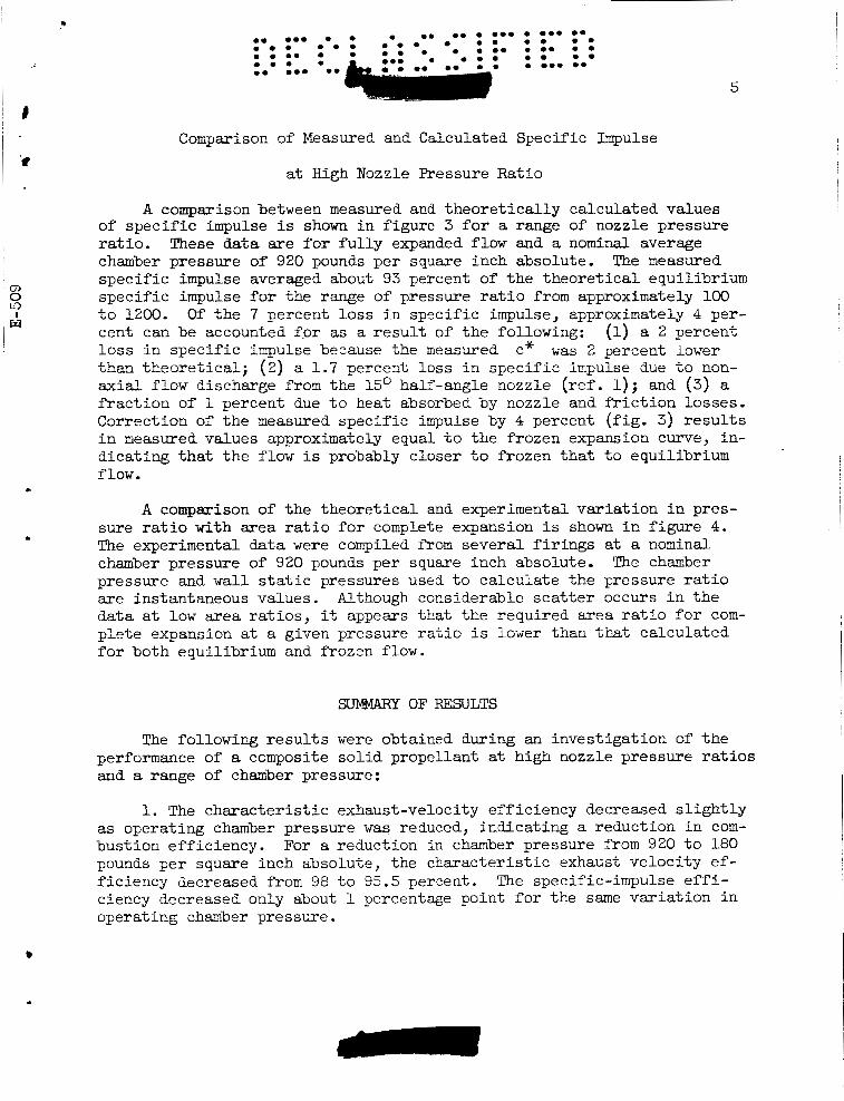
Comparison of Measured and Calculated Specific Impulse
at High Nozzle Pressure Ratio
5
A comparison between measured and t h e o r e t i c a l l y calculated values
These data are f o r f u l l y expanded flow and a nominal average of s p e c i f i c impulse is shown i n figure 3 f o r a range of nozzle pressure r a t i o . chamber pressure of 920 pounds per s q u a r e inch absolute. s p e c i f i c impulse averaged about 93 percent of t h e t h e o r e t i c a l equilibrium s p e c i f i c impulse f o r the range of pressure r a t i o from approximately 100 t o 1200. Of t h e 7 percent loss i n spec i f ic impulse, approximately 4 per- cent can be accounted f o r as a r e s u l t of t h e following: (1) a 2 percent l o s s i n s p e c i f i c impulse because the measured than theore t ica l ; (2) a 1 .7 percent loss i n s p e c i f i c impulse due t o non- a x i a l flow discharge from the 15' half-angle nozzle (ref. 1); and (3) a f r a c t i o n of 1 percent due t o heat absorbed by nozzle and f r i c t i o n losses . Correction of t h e measured spec i f ic impulse by 4 percent ( f ig . 3) r e s u l t s i n measured values approximately equal to the frozen expansion curve, in- d ica t ing that t h e flow is probably closer t o frozen t h a t t o equilibrium f l o w .
The measured
c* w a s 2 percent lower
A comparison of t h e t h e o r e t i c a l and experimental v a r i a t i o n i n pres- sure r a t i o with area r a t i o f o r complete expansion i s shown i n f igure 4. The experimental data were compiled from severa l f i r i n g s at a nominal chamber pressure of 920 pounds per square inch absolute. The chamber pressure and w a l l s t a t i c pressures used t o ca lcu la te the pressure r a t i o a r e instantaneous values. Although considerable s c a t t e r occurs i n t h e data a t low area r a t i o s , it appears t h a t t h e r equ i r ed a rea r a t i o f o r com- p l e t e expansion at a given pressure r a t i o i s lower than that calculated f o r both equilibrium and frozen flow.
SUMMARY OF RESULTS
The following r e s u l t s were obtained during an invest igat ion of t h e performance of a composite s o l i d propellant at high nozzle pressure r a t i o s and a range of chamber pressure:
1. The c h a r a c t e r i s t i c exhaust-velocity eff ic iency decreased s l i g h t l y as operating chamber pressure w a s reduced, indicat ing a reduction i n com- bustion eff ic iency. For a reduction i n chamber pressure from 920 t o 180 pounds per s q u a r e inch absolute, the charac te r i s t ic exhaust ve loc i ty ef- f ic iency decreased from 98 t o 95.5 percent. ciency decreased only about 1 percentage point f o r the same v a r i a t i o n i n operating chmber pressure.
The specific-impulse e f f i -

6
0 . 0. . . ... . 0 . 0 . . . . 0.. 0 . 0 . 0 . 0 . . e . . 0 . . 0 . .
0 . 0 . . e . . . . 0 . 0 . 0 . 0 . 0.. 0 . . :- 0 . . ... 0 . . 0 .
2. Measured values of s p e c i f i c impulse averaged about 7 percent lower than calculated equilibrium flow values f o r a range of pressure r a t i o f rom 100 t o 1200. proximately 4 percent could be accounted f o r by considering combustion ineff ic iency and nozzle t h r u s t losses . impulse were corrected for nozzle and combustion inef f ic ienc ies , the measured s p e c i f i c impulse w a s approximately e q u a l t o t h e calculated values f o r frozen flow.
9 O f t h i s 7 percent l o s s i n spec i f ic impulse, ap-
When measured values of s p e c i f i c
Lewis Research Center National Aeronautics and Space Administration
Cleveland, Ohio, July 10, 1959
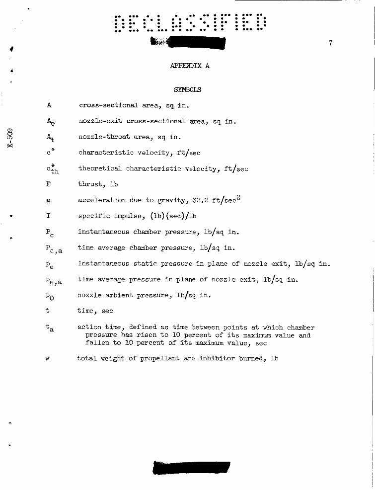
A
Ae At C*
* 'th
F
g
I
pC
'c,a
Pe
Pe,a
PO
t
ta
W
....... ............... . . . . . . . . . . . . . . . . .................. . . . . . . . . . . . . . . . . ........................ 7
cross-sectional mea, sq in .
nozzle-exit cross-sectional area, s q i n .
nozzle-throat mea , sq in .
charac te r i s t ic veloci ty , f t / sec
t h e o r e t i c a l c h a r a c t e r i s t i c velocity, f t / sec
t h r u s t , lb
accelerat ion due t o gravity, 32.2 f t / sec2
s p e c i f i c impulse, (lb) (sec) /lb
instantaneous chamber pressure, lb/sq in .
time average chamber pressure, lb/sq i n .
instantaneous s t a t i c pressure i n plane of nozzle e x i t , lb/sq i n .
time average pressure i n plane of nozzle e x i t , lb/sq in.
nozzle ambient pressure, lb/sq in .
t i m e , see
ac t ion time, defined as time between points at which chamber pressure has r i s e n t o 10 percent of i t s maximum value and f a l l e n t o 10 percent of i t s m a x i m u m value, sec
t o t a l weight of propellant and i n h i b i t o r burned, lb

8
CALCULATION PROCEDURE
No attempt w a s made t o measure the instantaneous gas-flow r a t e be- cause of t h e d i f f i c u l t y encountered with s o l i d propel lants , and therefore an average c h a r a c t e r i s t i c veloci ty w a s calculated i n the conventional manner :
where P, d t represents the a rea under t h e pressure-time curve. The
value of w equals the t o t a l weight of burned propel lant and i n h i b i t o r and w a s obtained by weight measurements of t h e propellant and i n h i b i t o r before and a f t e r f i r i n g .
s
e. e.. e e.. e e. e. e e e e.. e. e . e . e . e e . . e . . e . . e . e . . e . . e e e . e e e . . . e . . e e . . e e.. e e e . . e. e.. e e e e. e. . e e.. e. e.. e.
Specific impulse w a s calculated from experimental data as follows: *
$I? d t I =
W
where F dt represents the a rea under the thrust-t ime curve. The value
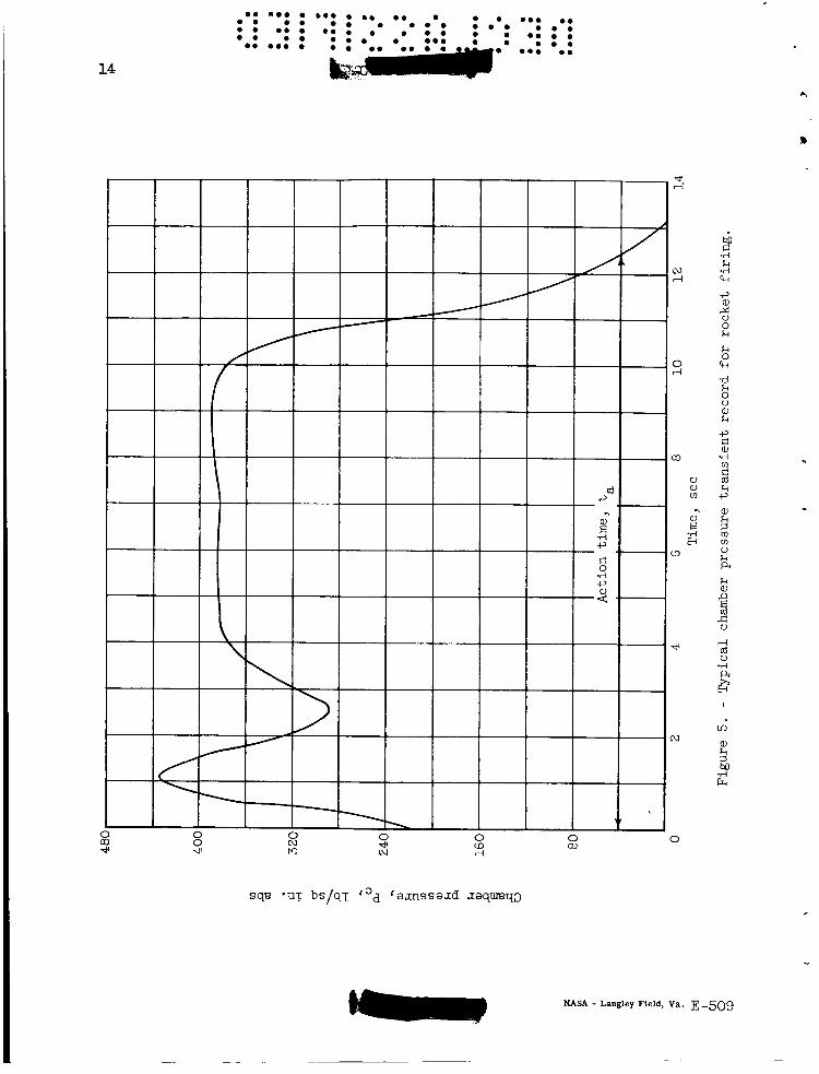
of I thus calculated is an average value s i m i l a r t o e*, s ince the chamber pressure (and, therefore , t h r u s t ) var ies with time as indicated i n f igure 5. pressure r a t i o var ies . I n order t o correct the measured t h r u s t t o rep- resent f u l l y expanded flow, the following procedure w a s followed. average chamber pressure w a s determined:
J Because the chamber pressure i s not constant, the nozzle
An
- S p c dt
Pc,a - ta
where ta represents the ac t ion time (see f i g . 5) . The r a t i o of chamber pressure t o nozzle-exit pressure w a s calculated from chamber-pressure and wall-pressure measurements. r a t i o s neax design, an average value of nozzle-exit pressure w a s calculated:
Since t h i s r a t i o i s constant f o r pressure
a
~
9
The value of pe.a then represents the average value of nozzle-exit
equal t o po f o r f u l l y expanded flow, the measured value pressure f o r f u l l y expanded f l o w . Since by de f in i t i on p
corrected by subtract ing t h e Ae(pe - po) term from the measured t h r u s t as follows:
d t ( f u l l y expanded) = d t -Ae(pe - po)ta
Theoretical calculat ions were made with the a id of a high-speed dig- ital computer using the thermodynamic data, equations, and procedures described i n references 2 and 3, Values of heats of formation of ammo- nium perchlorate (ref. 4) , polyvinyl chloride (ref. 5) , and dibutylseba- ca te (ref. 5) used were -69.42, -20.64, and -285.04 ki loca lor ies per gram, respect ively. The theo re t i ca l performance calculat ions assumed t h a t the propel lant consisted of only the fue ls and the oxidizer. The small per- centages of carbon black, s t a b i l i z e r , and v iscos i ty depressant , which are primarily organic, were added t o the polyvinyl chlor ide i n order t o s i m - p l i f y t h e calculat ions.
1. Sutton, George P.: Rocket Propulsion Elements. Second ea., John Wiley & Sons, Inc., 1956,
2 , Huff, Vearl N., Gordon, Sanford, and Morrell, Virginia E.: General Method and Thermodynamic Tables for Computation of Equilibrium Com- pos i t ion and Temperature of Chemical Reactions. NACA Rep. 1037, 1951. (Supersedes NACA T"s 2113 and 2161,)
3. Gordon, S., Zeleznik, F, J., and H u f f , V. N.: GeneralMethod f o r Automatic Computation of Equilibrium Compositions and Theoretical Rocket Performance of Propellants. NASA TN D-132, 1959.
4. Rossini, Frederick D., e t al.: Selected Values of Chemical Thermo- dynamic Propert ies . C i r . 500, NBS, 1952.
5. Fasber, Milton, and Altman, David.: culatLons on Composite Sol id Propellants. Rep. 20-73, Jet Prop. Lab. , C.1.T. , Dec. 15, 1953.
Compilation of Performance C a l -
(Contract DA-04-495-ORD-18.)
10
............... . . 0.. 0 . . . . . . . . . . . . . . . . . . . . . . . . . . . . . . . . . . . . . . . . . . . . . . ...... k-.' 0. : ' 0 :
cn 0
w Y
A
0. 0 0 0 0 0 0 0 0 0 0 0 0.0 0 0.0 0. 0 . 0 0 . 0 0 0 . 0 0 . 0 0 0 0 0 . 0 0 0 0 0 0 0 0 0 0 0 0 0 0 0 0
0 0 0 0 0 O U . 0 0 0 0 .. 0. 0 0 0.0 0 0 0 0 8 0 0 0 0 0 0 0 0 0 0 0 0 0
11
0

12
0 . 0.. . 0.. . 0 . 0 . . . . ... 0 . 0 . 0 . . 0 . . 0 . . . 0 . 0 . . ... . . 0 . . . 0 .
0 . 0 . .*. 0 . . :.,.. 0 . 0 . .
k 0 k
0 .r( c, (d
a, k 2 W k a a, rl N N
!2
0 CD
e, ‘c,
M W rl
W P I
M V d R
3 g

1
0 0
I .
13
0 N m
a, L 2 m a, L a L a, 0 E m 2 0
a, bo m a, > 4
51 d m c Ld a X a, a, 42
14
I sq8 *UT bs/q-[: raxnssaJd xaqmq3
............... ....... . . . . . . . . . . . . . . . . 0 . . . . . . . . . . . . . . . . . . . 0 . 0 .0 . . . . ...... g w ......
NASA - Langley Field, Va. E-509 -