prepared by : henal soni 130460106102 neel patwa 130460106075 dinesh prajapati 130460106078
TRANSCRIPT

SURVEYING
UNIVERSAL COLLEGE OF ENGG.
AND TECH.
LATITUDE & DEPARTURE PREPARED BY :
HENAL SONI 130460106102 NEEL PATWA 130460106075 DINESH PRAJAPATI 130460106078
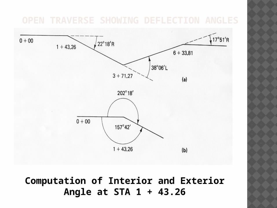
OPEN TRAVERSE SHOWING DEFLECTION ANGLES
Computation of Interior and Exterior Angle at STA 1 + 43.26
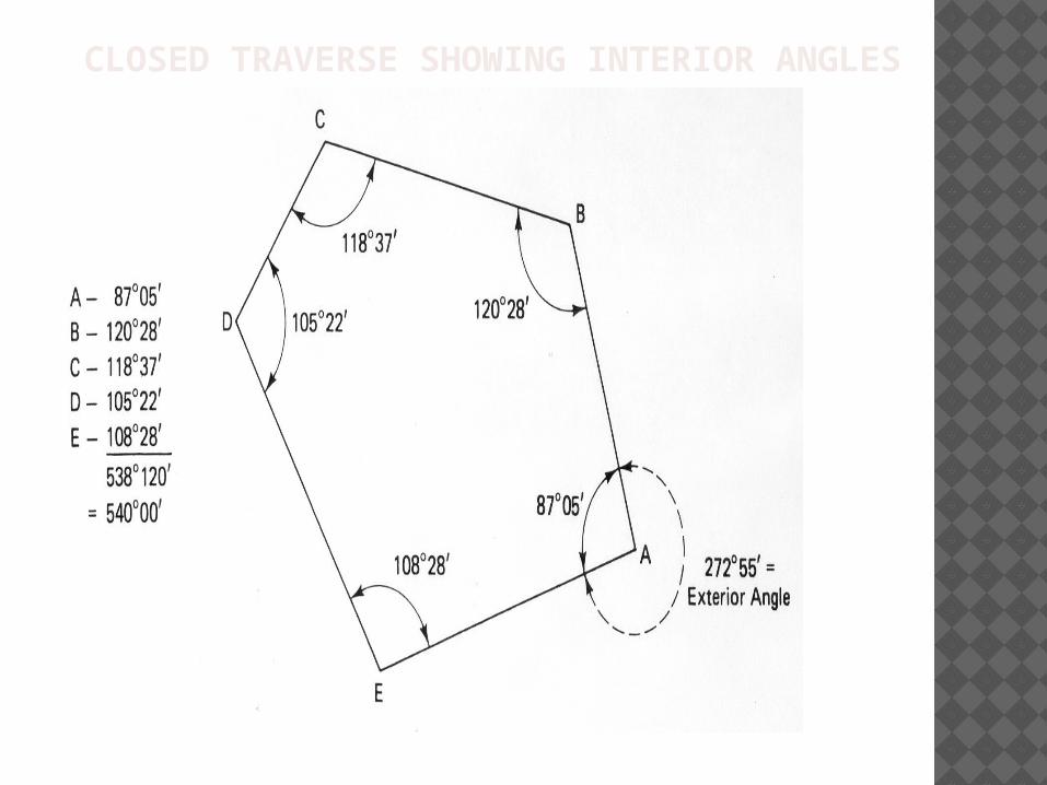
CLOSED TRAVERSE SHOWING INTERIOR ANGLES
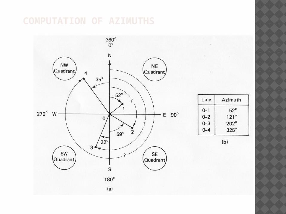
COMPUTATION OF AZIMUTHS
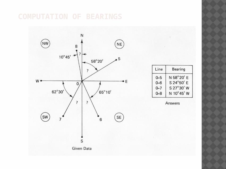
COMPUTATION OF BEARINGS
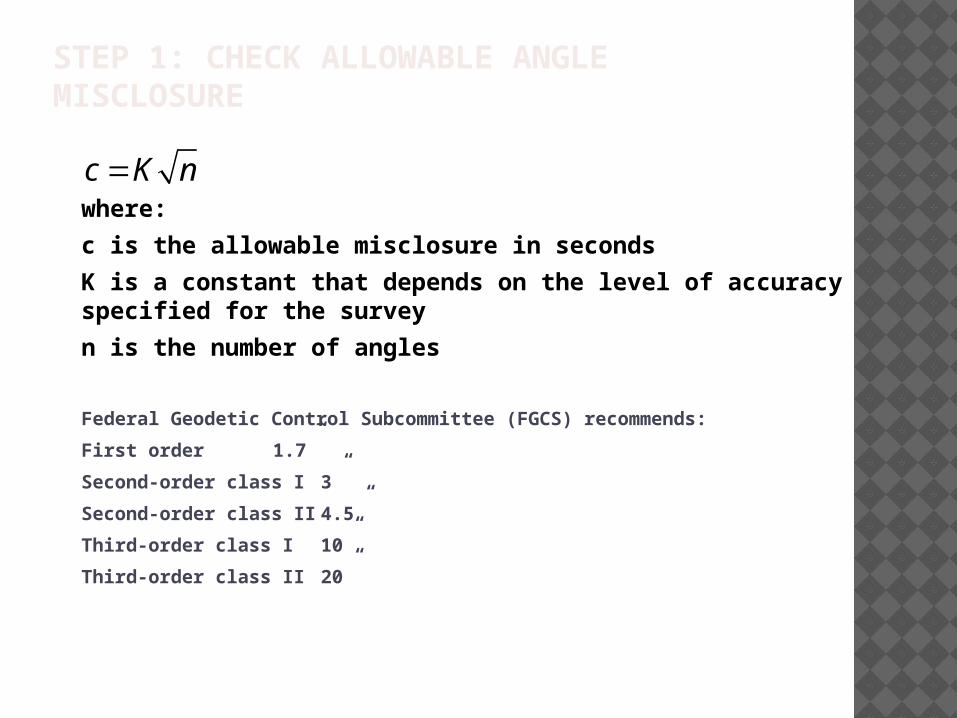
STEP 1: CHECK ALLOWABLE ANGLE MISCLOSURE
c K nwhere:
c is the allowable misclosure in seconds
K is a constant that depends on the level of accuracy specified for the survey
n is the number of angles
Federal Geodetic Control Subcommittee (FGCS) recommends:
First order 1.7”
Second-order class I 3”
Second-order class II 4.5”
Third-order class I 10”
Third-order class II 20”
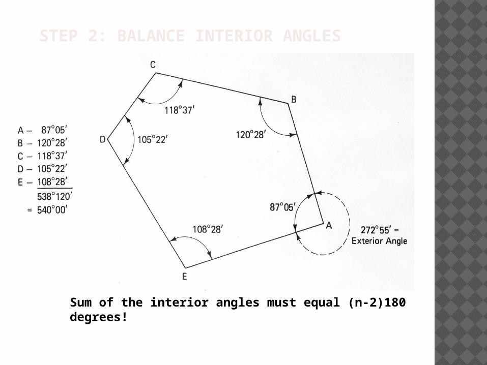
STEP 2: BALANCE INTERIOR ANGLES
Sum of the interior angles must equal (n-2)180 degrees!
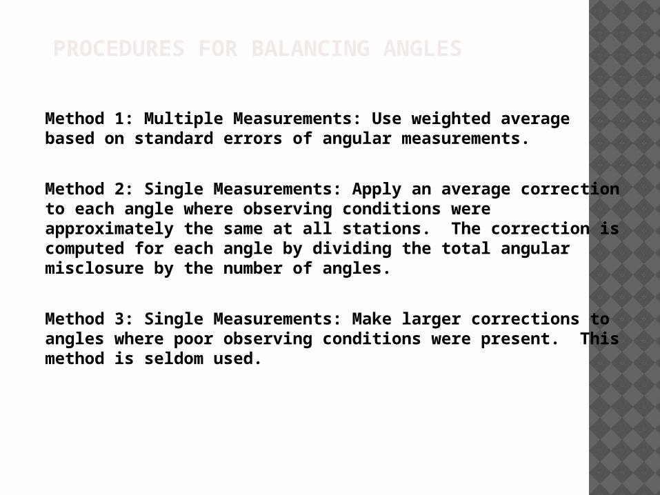
PROCEDURES FOR BALANCING ANGLES
Method 1: Multiple Measurements: Use weighted average based on standard errors of angular measurements.
Method 2: Single Measurements: Apply an average correction to each angle where observing conditions were approximately the same at all stations. The correction is computed for each angle by dividing the total angular misclosure by the number of angles.
Method 3: Single Measurements: Make larger corrections to angles where poor observing conditions were present. This method is seldom used.
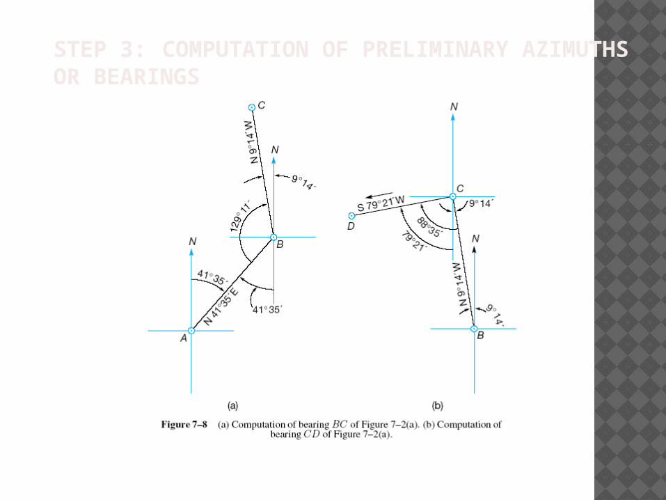
STEP 3: COMPUTATION OF PRELIMINARY AZIMUTHS OR BEARINGS
STEP 3: COMPUTATION OF PRELIMINARY AZIMUTHS OR BEARINGS (CONTINUED)
Beginning at the reference meridian compute the azimuth or bearing for each leg of the traverse.
Always check the last leg of the traverse to make sure that you compute the same azimuth or bearing as the reference meridian.
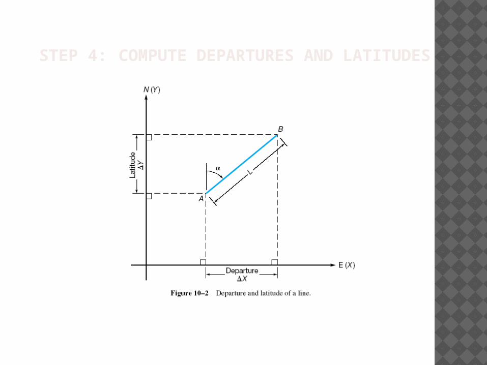
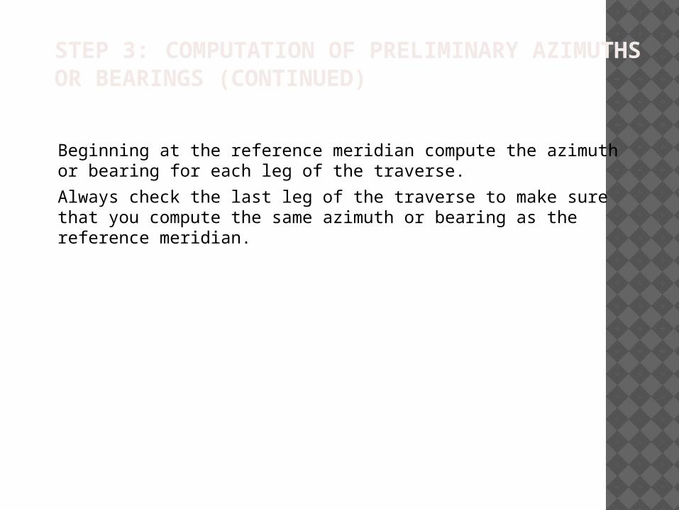
STEP 4: COMPUTE DEPARTURES AND LATITUDES
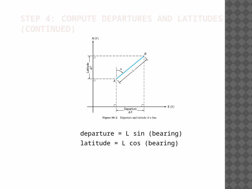
STEP 4: COMPUTE DEPARTURES AND LATITUDES (CONTINUED)
departure = L sin (bearing)
latitude = L cos (bearing)
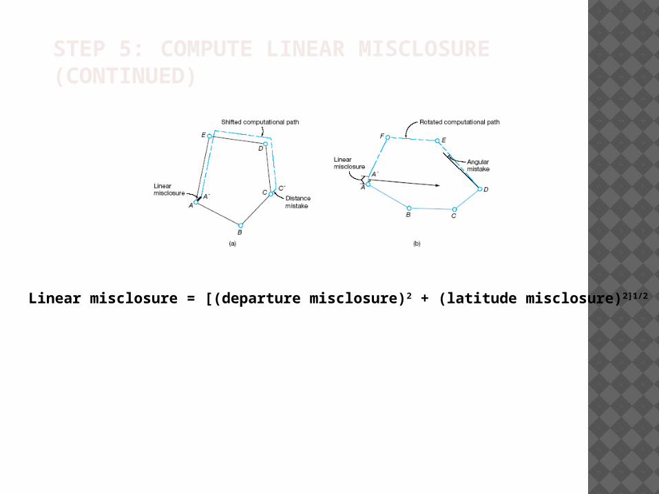
STEP 5: COMPUTE LINEAR MISCLOSURE (CONTINUED)
Linear misclosure = [(departure misclosure)2 + (latitude misclosure)2]1/2
STEP 6: COMPUTE RELATIVE PRECISION
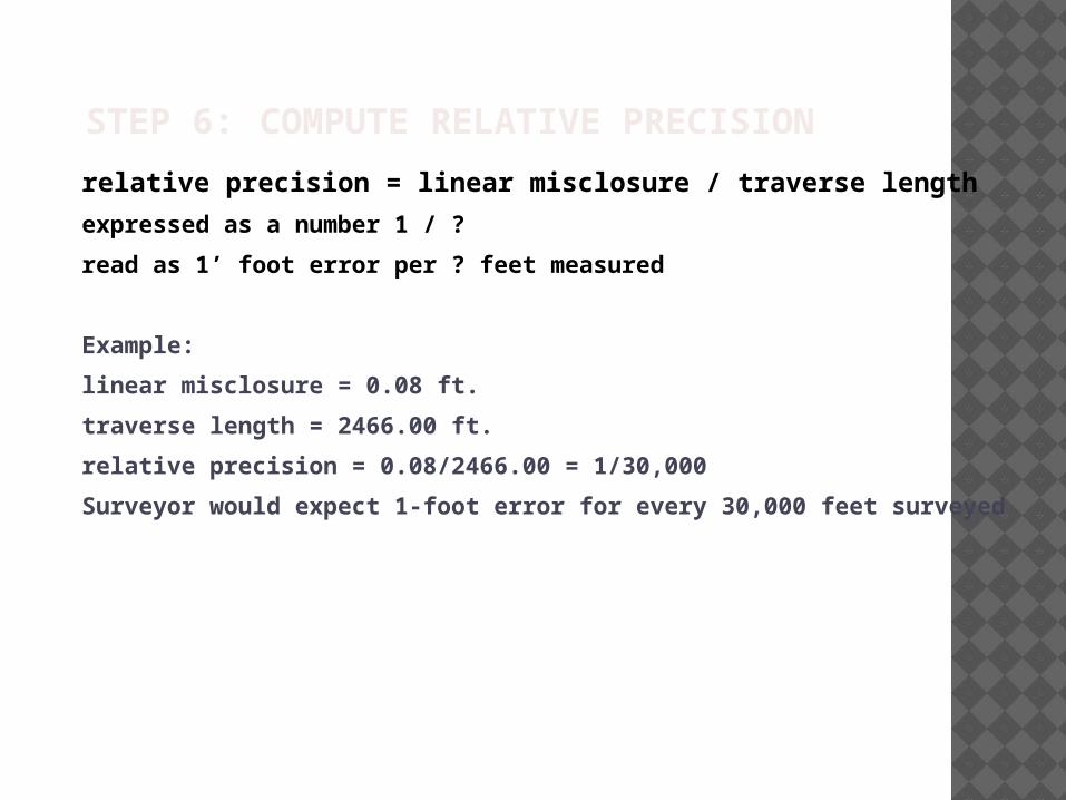
relative precision = linear misclosure / traverse length
expressed as a number 1 / ?
read as 1’ foot error per ? feet measured
Example:
linear misclosure = 0.08 ft.
traverse length = 2466.00 ft.
relative precision = 0.08/2466.00 = 1/30,000
Surveyor would expect 1-foot error for every 30,000 feet surveyed
STEP 7: ADJUST DEPARTURES AND LATITUDES
Methods:
Compass (Bowditch) Rule:
correction in departure for AB = - [(total departure misclosure)/(traverse perimeter)](length of AB)
correction in latitude for AB = - [(total latitude misclosure)/(traverse perimeter)](length of AB)
Adjusts the departures and latitudes of the sides of the traverse in proportion to their lengths.
Least Squares Adjustment:
Rigorous but best method based on probabilistic approach which models the occurrence of random errors. Angle and distance measurements are adjusted simultaneously. Most computer programs employ a least square adjustment methodology.
For more information on Least Squares Method see Chapter 15 in your textbook.
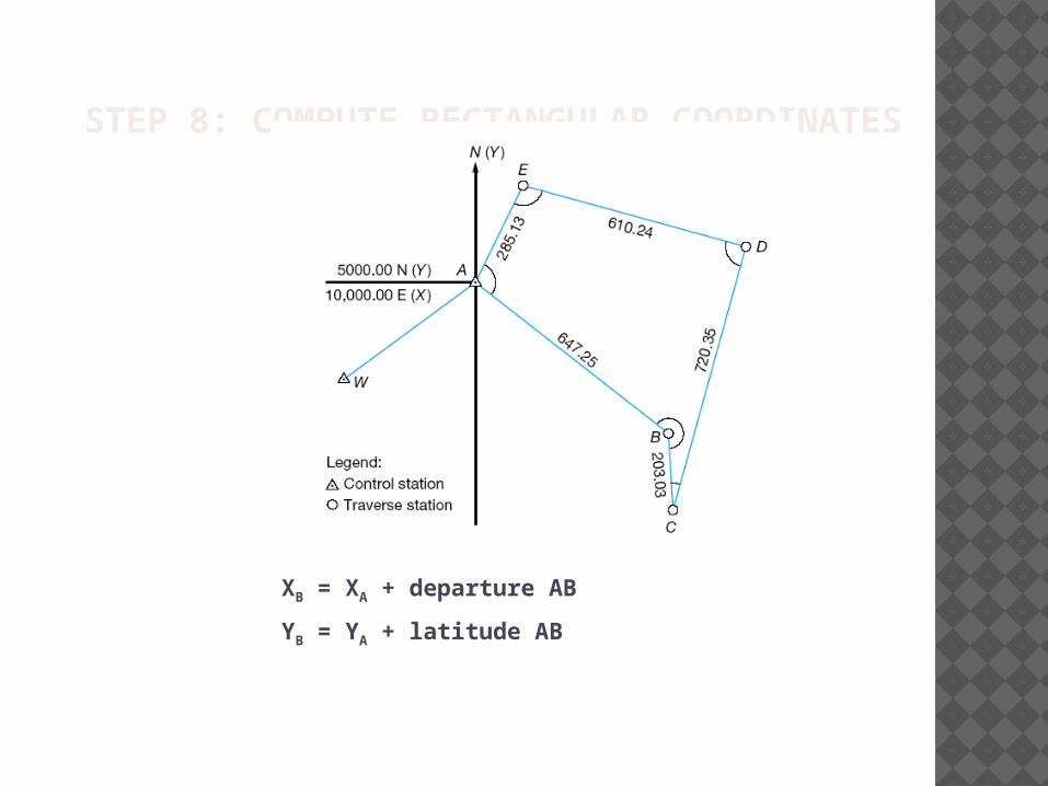
STEP 8: COMPUTE RECTANGULAR COORDINATES
XB = XA + departure AB
YB = YA + latitude AB
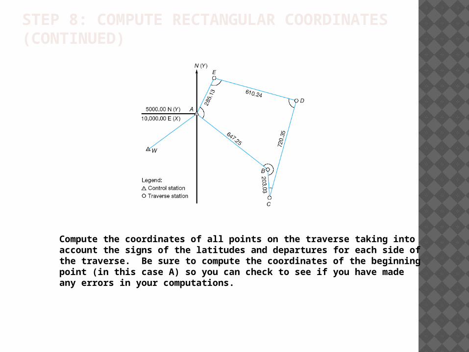
STEP 8: COMPUTE RECTANGULAR COORDINATES (CONTINUED)
Compute the coordinates of all points on the traverse taking into account the signs of the latitudes and departures for each side of the traverse. Be sure to compute the coordinates of the beginning point (in this case A) so you can check to see if you have made any errors in your computations.
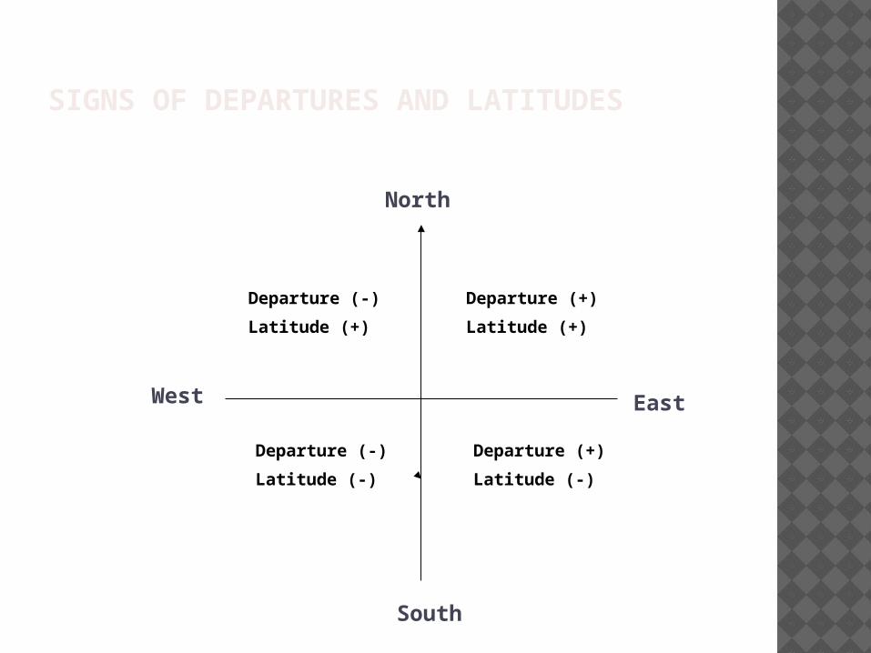
SIGNS OF DEPARTURES AND LATITUDES
North
EastWest
South
Departure (+)
Latitude (+)
Departure (-)
Latitude (+)
Departure (+)
Latitude (-)
Departure (-)
Latitude (-)