- metso-bulgaria.commetso-bulgaria.com/files/nasipni_materiali/broshura zadvijvane na... · ......
TRANSCRIPT
www.metsominerals.comB
ulk M
aterials Han
dlin
gw
ww
.metso
min
erals.com
Railcar and Barge Handling
Subject to alteration without prior notice Brochure No. 1824-02-05-MPR/York-English © 2005 Metso Minerals Printing in U.S.A.
Apron FeedersWobbler FeedersRailcar & Barge PullersRailcar IndexersAsh Submerged Chain ConveyorsAsh Dry Chain ConveyorsFly Ash Mixer ConditionersEn-Masse Conveyors/ElevatorsCoal Preparation EquipmentThrowers & Ship Trimmers
Machine Upgrades/RetrofitsService Life Extension ProjectsEquipment InspectionsOperations & Maintenance TrainingStart-Up Assistance/CommissioningAnnual Service AgreementsTroubleshooting ServicesBreakdown AssistanceReplacement Parts
Metso Minerals Industries, Inc. Metso Minerals North and Central America1500 Corporate Drive, Suite 300 240 Arch StreetCanonsburg, PA 15317 York, PA 17403USA USAPhone:+1-412-269 5000 Phone:+1-717-843 8671Fax: +1-412-269 5070 Fax: +1-717-845 5154
Metso Minerals South AmericaAv. Independência, 2500 Eden18087-050 SorocabaBrazilPhone:+55-15-2102-1300Fax: +55-15-2102-1699
Metso Minerals Asia-PacificP.O. Box 399West Perth, WA 6872AustraliaPhone:+61-8-9420-5555Fax: +61-8-9320-2500
Metso Minerals Europe and MediterraneanNoorangsgatan 2P.O. Box 30273325 SalaSwedenPhone:+46-224-570-00Fax: +46-224-169-50
Metso Minerals Southern Africa64 Jet Park RoadJet Park, 1469South AfricaPhone:+27-11-961-4000Fax: +27-11-397-5960
Metso MineralsP.O. Box 30733101 TampereFinlandPhone:+358-20-484-140Fax: +358-20-484-141
www.metsominerals.comE-mail: [email protected]
Railcar Dumpers & PositionersBucketwheel Stacker/ReclaimersScraper ReclaimersShip and Barge LoadersStackers (Radial/Linear)Grab Type UnloadersContinuous Barge UnloadersCable Belt Overland ConveyorsSelf-Unloading Ship SystemsComplete Systems
Equipment & Systems Engineered Products Aftermarket Services
Standard Car Puller 4 - 5
Style 969 - One Way Car Puller 6 - 7
Style 970 - Single Drum Reversible Car Puller (< 14,000 # Pull) 8 - 9
Style 970 - Single Drum Reversible Car Puller (> 14,000 # Pull) 10 - 11
Style 1000 - Double Drum Reversible Car Puller 12 - 13
Accessories 14 - 15
Track Layouts for Wire Rope Car Pullers 16 - 17
RCM (Reversible Car Mover) 18 - 19
NOLAN HCM (Hydraulic Car Mover) 20 - 21
SCAMP (Stephens-Adamson Cylinder Actuated Mobile Puller) 22 - 23
Standard and Heavy Duty Barge Hauls 24 - 25
Systems - Railcar and Barge Handling 26 - 27
Index
2 3
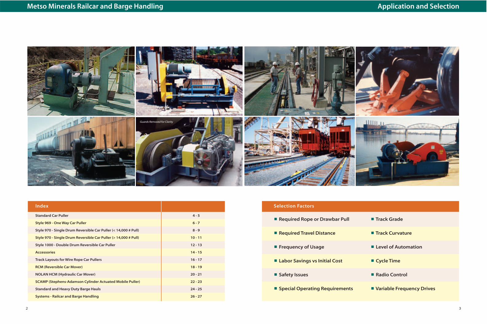
Metso Minerals Railcar and Barge Handling Application and Selection
Selection Factors
■ Required Rope or Drawbar Pull ■ Track Grade
■ Required Travel Distance ■ Track Curvature
■ Frequency of Usage ■ Level of Automation
■ Labor Savings vs Initial Cost ■ Cycle Time
■ Safety Issues ■ Radio Control
■ Special Operating Requirements ■ Variable Frequency Drives
Guards Removed for Clarity

4 5
Vertical Capstan and Horizontal Drum Pullers
Stephens-Adamson Horizontal Drum PullersStephens-Adamson Vertical Capstan Pullers
On horizontal drum car pullers, the rope isattached to the drum which eliminates the needfor snubbing and reduces handling of the rope.Up to 500 feet of rope can be stored on the drumwhen properly wound. Both the 14-H and 16-Hmodels feature a heavy-duty hand wheel clutchwhich releases the drum to pay out stored ropeand engages to pull without manual rope tension.
High starting torque TENV motors are standardequipment. Optional equipment includes ratchetholdbacks, special motors, holding brake, variablefrequency drive, sheaves, wire rope and electricalcontrols.
Designed for spotting railcars and adaptable tomany jobs requiring one-direction pulling.Operator attaches hook to car and manually snubsrope on capstan with sufficient tension for properoperating pull. Pulling distance is only limited bythe operator’s strength in handling the rope. Bothmodels are equipped with high starting torqueTENV motors. Optional equipment includes specialmotors and holding brake. Note the puller shouldnot be used to stop cars from coasting.
Bi-directional arrangement using sheaves ateither end of travel and horizontal car puller. Fleet Angle
TYPICAL TRACK LAYOUT
Dimensions in InchesModel
A B C D E F G H J K L M
14-H 12 28 27 391⁄4 9 2 31 131⁄2 22 2 1⁄2 2 1 1⁄2
16-H 12 28 29 391⁄4 9 2 31 131⁄2 22 2 1⁄2 2 1 1⁄2
Pulling CapacityRunning Rope PullMotor Rope Starting Wire Drum Weight
Model HP/ SpeedLayer
Pull* Rope Cap. (lbs.)RPM (fpm)
1 6 81st Layer Size (ft.)
14-H 10/1800 45 5,000 — 3,730 10,000 5⁄8 500 1,80016-H 71⁄2/900 28 7,800 4,730 — 15,600 3⁄4 400 2,000
* Starting rope pull represents a 100% overload on the motor and may besafely used for a six second period. Once the cars are started, the pull requiredto keep them moving drops approximately 50%. Torque ratings apply to baredrum diameter and decrease inversely proportional to radius as rope iswound on the drum.
DIMENSIONS
Dimensions in InchesModel
A B C D E EE F G H J K L M R
11-V 7 251⁄4 131⁄4 121⁄2 107⁄8 7 11⁄2 135⁄8 47⁄8 2 07⁄8 2 115⁄16 11⁄4 133⁄4
12-V 12 341⁄4 181⁄4 16 163⁄4 9 2 22 9 2 93⁄4 21⁄2 2 11⁄2 165⁄8
16-V 12 341⁄4 181⁄4 16 163⁄4 9 2 22 9 2 93⁄4 21⁄2 2 11⁄2 18
DIMENSIONS
SPECIFICATIONS
Pulling CapacityMotor RopeRope WeightModel HP/ SpeedSize (lbs.)RPM (fpm) Starting Running
11-V 5/1800 46 5,000 lbs. 2,500 lbs. 11⁄2 62012-V 10/1800 46 10,000 lbs. 5,000 lbs. 2 1,68016-V 15/1800 56 15,600 lbs. 7,800 lbs. 2 1,800
SPECIFICATIONS
Centrally located vertical capstan puller set up to pull one way on two tracks.
TYPICAL TRACK LAYOUT
NOTE: Use certified drawings for installation.
NOTE: Use certified drawings for installation.
▲CAUTION: Operators and other personnel should not be in the line of rope pull when the rope is under tension.
▲CAUTION: Operators and other personnel should not be in the line of rope pull when the rope is under tension.
Style 969
6
One Way Wire Rope Puller
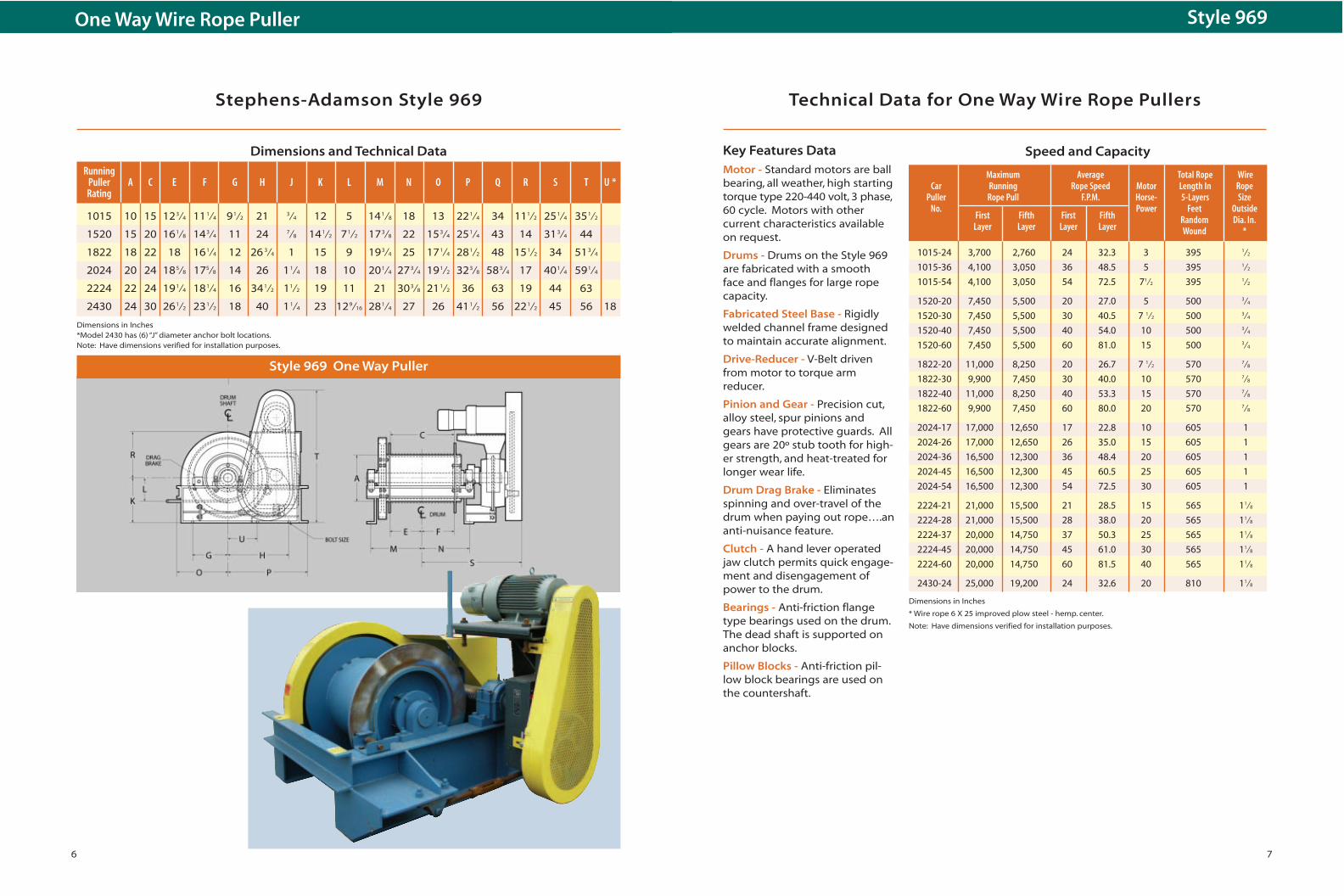
Stephens-Adamson Style 969 Technical Data for One Way Wire Rope Pullers
Motor - Standard motors are ballbearing, all weather, high startingtorque type 220-440 volt, 3 phase,60 cycle. Motors with other current characteristics availableon request.
Drums - Drums on the Style 969are fabricated with a smooth face and flanges for large ropecapacity.
Fabricated Steel Base - Rigidlywelded channel frame designedto maintain accurate alignment.
Drive-Reducer - V-Belt drivenfrom motor to torque arm reducer.
Pinion and Gear - Precision cut,alloy steel, spur pinions andgears have protective guards. Allgears are 20º stub tooth for high-er strength, and heat-treated forlonger wear life.
Drum Drag Brake - Eliminatesspinning and over-travel of thedrum when paying out rope….ananti-nuisance feature.
Clutch - A hand lever operatedjaw clutch permits quick engage-ment and disengagement ofpower to the drum.
Bearings - Anti-friction flangetype bearings used on the drum.The dead shaft is supported onanchor blocks.
Pillow Blocks - Anti-friction pil-low block bearings are used onthe countershaft.
Style 969 One Way Puller
7
Maximum Average Total Rope WireCar Running Rope Speed Motor Length In Rope
Puller Rope Pull F.P.M. Horse- 5-Layers SizeNo.
First Fifth First FifthPower Feet Outside
Layer Layer Layer LayerRandom Dia. In.Wound *
1015-24 3,700 2,760 24 32.3 3 395 1⁄2
1015-36 4,100 3,050 36 48.5 5 395 1⁄2
1015-54 4,100 3,050 54 72.5 71⁄2 395 1⁄2
1520-20 7,450 5,500 20 27.0 5 500 3⁄4
1520-30 7,450 5,500 30 40.5 7 1⁄2 500 3⁄4
1520-40 7,450 5,500 40 54.0 10 500 3⁄4
1520-60 7,450 5,500 60 81.0 15 500 3⁄4
1822-20 11,000 8,250 20 26.7 7 1⁄2 570 7⁄8
1822-30 9,900 7,450 30 40.0 10 570 7⁄8
1822-40 11,000 8,250 40 53.3 15 570 7⁄8
1822-60 9,900 7,450 60 80.0 20 570 7⁄8
2024-17 17,000 12,650 17 22.8 10 605 1
2024-26 17,000 12,650 26 35.0 15 605 1
2024-36 16,500 12,300 36 48.4 20 605 1
2024-45 16,500 12,300 45 60.5 25 605 1
2024-54 16,500 12,300 54 72.5 30 605 1
2224-21 21,000 15,500 21 28.5 15 565 11⁄8
2224-28 21,000 15,500 28 38.0 20 565 11⁄8
2224-37 20,000 14,750 37 50.3 25 565 11⁄8
2224-45 20,000 14,750 45 61.0 30 565 11⁄8
2224-60 20,000 14,750 60 81.5 40 565 11⁄8
2430-24 25,000 19,200 24 32.6 20 810 11⁄8
Speed and Capacity
RunningPuller A C E F G H J K L M N O P Q R S T U *Rating
1015 10 15 123⁄4 111⁄4 91⁄2 21 3⁄4 12 5 141⁄8 18 13 221⁄4 34 111⁄2 251⁄4 351⁄2
1520 15 20 161⁄8 143⁄4 11 24 7⁄8 141⁄2 71⁄2 173⁄8 22 153⁄4 251⁄4 43 14 313⁄4 44
1822 18 22 18 161⁄4 12 26 3⁄4 1 15 9 193⁄4 25 171⁄4 281⁄2 48 151⁄2 34 513⁄4
2024 20 24 185⁄8 175⁄8 14 26 11⁄4 18 10 201⁄4 273⁄4 191⁄2 323⁄8 583⁄4 17 401⁄4 591⁄4
2224 22 24 191⁄4 181⁄4 16 341⁄2 11⁄2 19 11 21 303⁄8 211⁄2 36 63 19 44 63
2430 24 30 261⁄2 231⁄2 18 40 11⁄4 23 129⁄16 281⁄4 27 26 411⁄2 56 221⁄2 45 56 18
Dimensions and Technical Data
Dimensions in Inches*Model 2430 has (6) “J” diameter anchor bolt locations.Note: Have dimensions verified for installation purposes.
Dimensions in Inches
* Wire rope 6 X 25 improved plow steel - hemp. center.
Note: Have dimensions verified for installation purposes.
Key Features Data

98 9
Single Drum Reversible Puller Under 14,000 Pound Capacity - Style 970
Stephens-Adamson Style 970 Technical Data for Pullers Rated Under 14,000 Pounds
Dimensions and Technical Data
Rope Circuit
Style 970 Single Drum Reversible Puller (Shaft Mounted Reducer)
Single Drum Shaft Mounted Reducer - Style 970single drum reversible (SDR) car pullers are gener-ally used where cars must be moved or controlledin both directions along a track and where thelength of travel is not in excess of the practicalcapacity of a single layer of rope on the drum.They also eliminate the necessity of manually relo-cating the hook. Since only a single layer of ropeon the drum is used, there is a limit of practicablepulling distance, usually 500 feet. All single drumreversible systems require a closed rope circuit.
Drive - The speed reducer is mounted on anddrives the countershaft. The motor sits on anadjustabale base and drives the input shaftthrough a V-belt drive.
Operation - The hook arrangement for this puller
is shown on page 15. Both ends of the rope deadend at the drum and as the rope is wound ontothe drum on one end, the same amount of rope ispaid off the other end. The load is under positivecontrol in both directions. There is a “gap” of oneor more empty grooves on the drum. As the drumis turned, the “gap” moves across the face of the
drum. At least two full anchoring wraps are ateach end. Manually adjustable turn buckle, take-up sheaves are always used with SDR pullers.
Limit Switches - All 970 SDR car pullers include astandard limit switch arrangement devised toprotect against “double wrapping” of the rope onthe drum or against the possibility of the ropecoming out of the grooves. Also furnished is arotary type travel limit switch to prevent the hitchrope hardware from contacting the terminalsheaves. Because the switch is conveniently locat-ed, the protective interlock wiring is simple andless costly than that required for the conventionalfork and lever switch on the double drum contin-uous puller.
Speed and Capacity
Running Max. Wire Model Rope* Rope Rope A B C D E F H I J K L M N
No. Pull Travel Size
1624-7 7,000 120 5⁄8 16 24 18 7⁄8 15 5⁄8 12 21 33 23 1⁄8 18 30 15 48 7⁄8
1636-7 7,000 195 5⁄8 16 36 24 7⁄8 21 5⁄8 12 21 39 29 1⁄8 18 30 15 48 7⁄8
2036-7 7,000 245 5⁄8 20 36 24 7⁄8 21 5⁄8 12 21 39 29 1⁄8 18 30 15 48 7⁄8
2436-7 7,000 290 5⁄8 24 36 24 7⁄8 21 5⁄8 12 21 44 29 1⁄8 19 35 15 50 7⁄8
2448-7 7,000 400 5⁄8 24 48 30 7⁄8 27 5⁄8 12 21 50 35 1⁄2 19 35 15 50 7⁄8
3048-7 7,000 500 5⁄8 30 48 31 27 1⁄2 15 30 47 3⁄4 35 1⁄4 22 1⁄2 38 19 53 7⁄8
2036-10 10,000 205 3⁄4 20 36 24 1⁄2 21 1⁄2 12 24 44 29 19 35 15 56 1⁄2 12436-10 10,000 250 3⁄4 24 36 24 1⁄2 21 1⁄2 12 24 44 29 19 35 15 56 1⁄2 12448-10 10,000 345 3⁄4 24 48 30 1⁄2 27 1⁄2 12 24 50 35 19 35 15 56 1⁄2 13048-10 10,000 430 3⁄4 30 48 31 15⁄16 29 1⁄16 15 30 51 1⁄2 36 1⁄2 22 1⁄2 38 19 58 13060-10 10,000 550 3⁄4 30 60 37 15⁄16 35 1⁄16 15 30 57 1⁄2 42 1⁄2 22 1⁄2 38 19 58 1
2036-14 14,000 160 7⁄8 20 36 25 22 7⁄8 14 28 44 3⁄4 29 1⁄2 20 1⁄2 35 1⁄2 18 60 11⁄4
2436-14 14,000 195 7⁄8 24 36 25 22 7⁄8 14 28 44 3⁄4 29 1⁄2 20 1⁄2 35 1⁄2 18 60 11⁄4
2448-14 14,000 270 7⁄8 24 48 31 28 7⁄8 14 28 50 3⁄4 35 1⁄2 20 1⁄2 35 1⁄2 18 60 11⁄4
Rating 7,000
Speed F.P.M. 20 30 40 60Motor H.P. 5 71⁄2 10 15
10,000
Speed F.P.M. 14 21 28 42 56Motor H.P. 5 71⁄2 10 15 20
14,000
Speed F.P.M. 15 20 30 40 50 60Motor H.P. 71⁄2 10 15 20 25 30
Dimensions in Inches*Wire rope 6 x 25 extra improved plow steel I.W.R.C.Note: Have dimensions verified for installation purposes.

1110
Single Drum Reversible Puller Over 14,000 Pound Capacity - Style 970
Technical Data for Pullers Rated Over 14,000 PoundsStephens-Adamson Style 970
Bearings - Anti-friction flange type bearings areused on drum. Dead shaft supported on anchorblocks.
Pillow Blocks - Anti-friction pillow block bearingsare used on countershaft.
Limit Switches - Rotary type limit switch drivenfrom countershaft to control travel limits is stan-dard equipment on all Style 970 pullers.
Hook Arrangement - Typical hook arrangement,shown on page 15, normally used with single drumor double drum car pullers for two-way movementof cars. See pages 16 and 17 for typical track lay-outs.
Chain Drive and Concentric Type Reducer - Moresuitable for the higher torque requirements. Drumreeving and dead-ending is the same as shown onpage 9. The limit of rope travel is approximately500 feet.
Drum - Hardened steel grooves to the diameter ofwire rope used. Ends of drums are machined withan indexing shoulder to insure concentricity of thedrum gear.
Pinion and Gear - Precision cut, alloy steel, spurpinions and gears with protective guards. Allgears are 20° stub tooth for higher strength andheat-treated for longer wear life.
Dimensions and Technical Data
Running Max. Wire Model Rope* Rope Rope A B C D E F G H I J K L M N
No. Pull Travel Size
3048-14 14,000 335 7⁄8 30 48 32 1⁄2 28 1⁄2 16 32 26 36 37 22 1⁄2 66 3⁄8 20 42 13060-14 14,000 430 7⁄8 30 60 38 1⁄2 34 1⁄2 16 32 26 42 43 22 1⁄2 66 3⁄8 20 42 1 3660-14 14,000 515 7⁄8 36 60 41 1⁄2 37 1⁄2 18 36 30 45 1⁄4 46 25 3⁄4 73 1⁄4 23 45 1⁄4 1
2436-18 18,000 165 1 24 36 29 5⁄8 26 1⁄8 16 32 26 34 7⁄8 34 22 1⁄2 66 1⁄4 20 42 1⁄4 11⁄8
2448-18 18,000 230 1 24 48 35 5⁄8 32 1⁄8 16 32 26 40 7⁄8 40 22 1⁄2 66 1⁄4 20 42 1⁄4 11⁄8
3048-18 18,000 290 1 30 48 35 5⁄8 32 1⁄8 18 36 30 40 7⁄8 40 25 3⁄4 73 1⁄4 23 47 3⁄4 11⁄8
3060-18 18,000 370 1 30 60 41 5⁄8 38 1⁄8 18 36 30 46 7⁄8 46 25 3⁄4 73 1⁄4 23 47 3⁄4 11⁄8
3660-18 18,000 445 1 36 60 41 5⁄8 38 1⁄8 18 36 30 46 7⁄8 46 25 3⁄4 73 1⁄4 23 47 3⁄4 11⁄8
3672-18 18,000 545 1 36 72 47 5⁄8 44 1⁄8 18 36 30 52 7⁄8 52 25 3⁄4 73 1⁄4 23 47 3⁄4 11⁄8
2436-23 23,000 150 1 1⁄8 24 36 29 5⁄8 26 1⁄8 18 36 30 34 7⁄8 34 25 3⁄4 73 1⁄4 22 47 1⁄4 11⁄4
2448-23 23,000 210 1 1⁄8 24 48 35 5⁄8 32 1⁄8 18 36 30 40 7⁄8 40 25 3⁄4 73 1⁄4 22 47 1⁄4 11⁄4
3048-23 23,000 265 1 1⁄8 30 48 36 3⁄8 33 5⁄8 18 36 30 42 7⁄8 40 7⁄8 25 3⁄4 75 23 48 11⁄4
3060-23 23,000 345 1 1⁄8 30 60 42 3⁄8 39 5⁄8 18 36 30 48 1⁄16 46 7⁄8 25 3⁄4 75 23 48 11⁄4
3660-23 23,000 410 1 1⁄8 36 60 42 3⁄8 39 5⁄8 18 36 30 47 1⁄2 46 7⁄8 25 3⁄4 75 23 46 11⁄4
3672-23 23,000 500 1 1⁄8 36 72 48 3⁄8 45 5⁄8 18 36 30 53 1⁄2 52 7⁄8 25 3⁄4 75 23 46 11⁄4
4272-23 23,000 585 1 1⁄8 42 72 49 3⁄8 46 5⁄8 22 42 34 54 1⁄2 52 5⁄8 28 1⁄2 83 1⁄4 26 52 11⁄4
3048-28 28,000 240 1 1⁄4 30 48 36 1⁄4 32 3⁄4 18 36 30 41 40 1⁄2 25 3⁄4 77 3⁄4 23 46 13⁄8
3060-28 28,000 310 1 1⁄4 30 60 42 1⁄4 38 3⁄8 18 36 30 47 46 1⁄2 25 3⁄4 77 3⁄4 23 46 13⁄8
3660-28 28,000 375 1 1⁄4 36 60 43 3⁄8 39 7⁄8 22 42 34 47 5⁄8 46 3⁄4 28 1⁄2 83 1⁄4 26 52 13⁄8
3672-28 28,000 460 1 1⁄4 36 72 49 3⁄8 45 7⁄8 22 42 34 53 5⁄8 52 3⁄4 28 1⁄2 83 1⁄4 26 52 13⁄8
4272-28 28,000 540 1 1⁄4 42 72 49 3⁄8 45 7⁄8 22 42 34 53 5⁄8 52 3⁄4 28 1⁄2 83 1⁄4 26 52 13⁄8
3048-34 34,000 220 1 3⁄8 30 48 37 1⁄8 33 5⁄8 22 42 36 43 1⁄8 41 1⁄8 28 1⁄2 84 1⁄2 25 50 11⁄2
3060-34 34,000 285 1 3⁄8 30 60 43 1⁄8 39 5⁄8 22 42 36 49 1⁄8 47 1⁄8 28 1⁄2 84 1⁄2 25 50 11⁄2
3660-34 34,000 340 1 3⁄8 36 60 44 40 22 42 36 49 1⁄2 48 28 3⁄4 84 3⁄4 25 1⁄2 53 11⁄2
3672-34 34,000 420 1 3⁄8 36 72 50 46 22 42 36 55 1⁄2 52 28 3⁄4 84 3⁄4 25 1⁄2 53 11⁄2
4272-34 34,000 490 1 3⁄8 42 72 50 1⁄2 46 1⁄2 24 42 36 56 1⁄2 54 1⁄2 32 1⁄2 91 1⁄2 30 59 11⁄2
Speed and Capacity
Rating 14,000Speed F.P.M. 15 20 30 40 50 60Motor H.P. 71⁄2 10 15 20 25 30
18,000Speed F.P.M. 15 23 31 39 46 62Motor H.P. 10 15 20 25 30 40
23,000Speed F.P.M. 12 18 24 30 36 48 61Motor H.P. 10 15 20 25 30 40 50
28,000Speed F.P.M. 15 20 30 40 50 60Motor H.P. 15 20 30 40 50 60
34,000Speed F.P.M. 16 20 24 33 41 49 61Motor H.P. 20 25 30 40 50 60 75
Style 970 Single Drum Reversible Puller (Concentric Mounted Reducer)
Dimensions in Inches *Wire rope 6 x 25 extra improved plow steel I.W.R.C.Note: Have dimensions verified for installation purposes.
CarPuller Wire Drum A B C D E * F * G H JRating Rope Size**
10,000 3⁄4 24 51 3⁄4 75 40 21 12' 4 3⁄8 18' 6 4' 1' 3 1' 6
14,000 7⁄8 24 54 3⁄4 78 40 21 12' 6 18' 6 4' 4 1' 3 1' 10 I⁄2
18,000 1 30 60 92 48 25 I⁄2 14' 8 20' 5' 6 1' 3 1' 10 I⁄2
23,000 1 1⁄8 30 47 I⁄2 91 59 28 I⁄2 14' 9 I⁄2 20' 5' 6 1' 3 2' 6
28,000 1 1⁄4 36 53 108 67 31 I⁄2 14' 10 3⁄4 20' 6' 1' 4 2' 9
34,000 1 3⁄8 36 54 111 69 36 I⁄2 15' 8 I⁄2 21' 6' 2' 2' 9
40,000 1 I⁄2 42 56 124 75 37 3⁄4 15' 8 I⁄2 21' 6' 2' 2' 9
1312
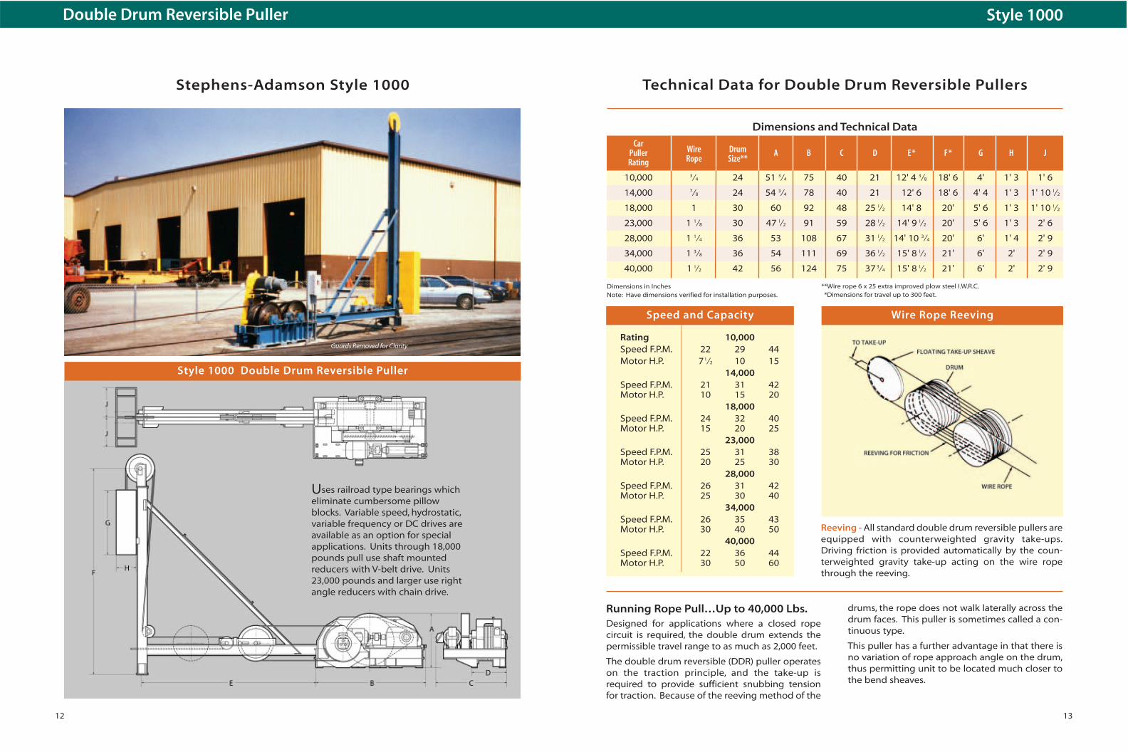
Double Drum Reversible Puller
Stephens-Adamson Style 1000 Technical Data for Double Drum Reversible Pullers
Reeving - All standard double drum reversible pullers areequipped with counterweighted gravity take-ups.Driving friction is provided automatically by the coun-terweighted gravity take-up acting on the wire ropethrough the reeving.
Running Rope Pull…Up to 40,000 Lbs.Designed for applications where a closed ropecircuit is required, the double drum extends thepermissible travel range to as much as 2,000 feet.
The double drum reversible (DDR) puller operateson the traction principle, and the take-up isrequired to provide sufficient snubbing tensionfor traction. Because of the reeving method of the
Uses railroad type bearings whicheliminate cumbersome pillowblocks. Variable speed, hydrostatic,variable frequency or DC drives areavailable as an option for specialapplications. Units through 18,000pounds pull use shaft mountedreducers with V-belt drive. Units23,000 pounds and larger use rightangle reducers with chain drive.
Speed and Capacity Wire Rope Reeving
Style 1000 Double Drum Reversible Puller
Rating 10,000Speed F.P.M. 22 29 44Motor H.P. 71⁄2 10 15
14,000Speed F.P.M. 21 31 42Motor H.P. 10 15 20
18,000Speed F.P.M. 24 32 40Motor H.P. 15 20 25
23,000Speed F.P.M. 25 31 38Motor H.P. 20 25 30
28,000Speed F.P.M. 26 31 42Motor H.P. 25 30 40
34,000Speed F.P.M. 26 35 43Motor H.P. 30 40 50
40,000Speed F.P.M. 22 36 44Motor H.P. 30 50 60
Dimensions and Technical Data
drums, the rope does not walk laterally across thedrum faces. This puller is sometimes called a con-tinuous type.
This puller has a further advantage in that there isno variation of rope approach angle on the drum,thus permitting unit to be located much closer tothe bend sheaves.
Guards Removed for Clarity
Dimensions in InchesNote: Have dimensions verified for installation purposes.
**Wire rope 6 x 25 extra improved plow steel I.W.R.C.*Dimensions for travel up to 300 feet.
Style 1000
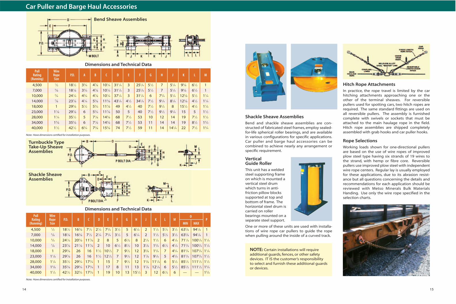
Vertical Guide RollerThis unit has a weldedsteel supporting frameon which is mounted avertical steel drumwhich turns in anti-friction pillow blockssupported at top andbottom of frame. Thehorizontal steel drum iscarried on rollerbearings mounted on aseparate steel support.
One or more of these units are used with installa-tions of wire rope car pullers to guide the ropewhen pulling around the inside of a curved track.
15
Rope SelectionsWorking loads shown for one-directional pullersare based on the use of wire ropes of improvedplow steel type having six strands of 19 wires tothe strand, with hemp or fibre core. Reversiblepullers use improved plow steel with independentwire rope centers. Regular lay is usually employedfor these applications, due to its abrasion resist-ance but all questions concerning the details andrecommendations for each application should bereviewed with Metso Minerals Bulk MaterialsHanding. Use only the wire rope specified in theselection charts.
Shackle Sheave AssembliesBend and shackle sheave assemblies are con-structed of fabricated steel frames, employ sealed-for-life spherical roller bearings, and are availablein various configurations for specific applications.Car puller and barge haul accessories can be combined to achieve nearly any arrangement orspecific requirement.
NOTE: Certain installations will requireadditional guards, fences, or other safetydevices. IT IS the customer’s responsibilityto select and furnish these additional guardsor devices.
Hitch Rope AttachmentsIn practice, the rope travel is limited by the carhitching attachments approaching one or theother of the terminal sheaves. For reversiblepullers used for spotting cars, two hitch ropes arerequired. The same standard fittings are used onall reversible pullers. The assembly is furnishedcomplete with swivels or sockets that must beattached to the main haulage rope in the field.Hitch rope assemblies are shipped completelyassembled with grab hooks and car puller hooks.
14
Car Puller and Barge Haul Accessories
Bend Sheave Assemblies
Turnbuckle Type Take-Up SheaveAssemblies
Shackle SheaveAssemblies
Pull Wire Rating Rope P.D. B C D E F G H J K L M
OP
(Running) Size MIN MAX
4,500 1⁄2 181⁄2 163⁄8 71⁄2 21⁄4 73⁄4 31⁄2 5 61⁄4 2 11⁄2 51⁄2 31⁄2 635⁄8 941⁄8 1
7,000 5⁄8 181⁄8 163⁄8 71⁄2 21⁄4 73⁄4 31⁄2 5 61⁄4 2 11⁄2 51⁄2 31⁄2 635⁄8 941⁄8 1
10,000 3⁄4 241⁄4 205⁄8 117⁄8 2 8 5 61⁄2 8 21⁄4 11⁄2 6 41⁄4 711⁄4 1001⁄4 11⁄4
14,000 7⁄8 237⁄8 211⁄8 117⁄8 2 10 61⁄2 81⁄2 10 31⁄8 13⁄4 61⁄2 41⁄4 713⁄4 1003⁄4 11⁄4
18,000 1 295⁄8 26 16 11⁄2 101⁄2 7 91⁄2 12 35⁄8 13⁄4 7 43⁄4 813⁄4 1073⁄4 11⁄4
23,000 11⁄8 297⁄8 26 16 11⁄2 121⁄2 7 91⁄2 12 17⁄8 91⁄4 5 43⁄4 813⁄4 1073⁄4 11⁄2
28,000 11⁄4 351⁄2 293⁄4 173⁄4 1 15 7 91⁄2 12 13⁄8 111⁄4 6 51⁄2 851⁄2 1111⁄2 11⁄2
34,000 13⁄8 355⁄8 293⁄4 173⁄4 1 17 8 11 13 17⁄8 121⁄4 6 51⁄2 851⁄2 1111⁄2 13⁄4
40,000 11⁄2 421⁄2 323⁄4 173⁄4 1 19 10 13 151⁄2 3 12 61⁄2 6 — — 13⁄4
Note: Have dimensions certified for installation purposes.
Note: Have dimensions certified for installation purposes.
Dimensions and Technical Data
Pull Wire Rating Rope P.D. A B C D E F G H J K L M
(Running) Size
4,500 1⁄2 181⁄2 33⁄4 47⁄8 101⁄4 311⁄4 3 251⁄4 51⁄2 7 51⁄4 95⁄8 61⁄2 1
7,000 5⁄8 181⁄8 33⁄4 47⁄8 101⁄4 311⁄4 3 251⁄4 51⁄2 7 51⁄4 95⁄8 61⁄2 1
10,000 3⁄4 241⁄4 43⁄4 47⁄8 101⁄4 371⁄4 3 311⁄4 6 73⁄4 51⁄4 125⁄8 51⁄2 11⁄4
14,000 7⁄8 237⁄8 41⁄4 55⁄8 115⁄8 431⁄4 41⁄2 341⁄4 71⁄2 91⁄4 81⁄4 125⁄8 41⁄2 11⁄4
18,000 1 295⁄8 51⁄2 53⁄4 117⁄8 49 41⁄2 40 71⁄2 91⁄2 8 151⁄2 41⁄2 11⁄4
23,000 11⁄8 297⁄8 6 53⁄4 117⁄8 50 5 40 71⁄2 91⁄2 91⁄4 15 5 11⁄2
28,000 11⁄4 351⁄2 5 71⁄8 143⁄8 68 71⁄2 53 10 12 14 19 71⁄2 11⁄2
34,000 13⁄8 355⁄8 6 71⁄8 143⁄8 68 71⁄2 53 11 14 14 19 81⁄2 13⁄4
40,000 11⁄2 421⁄2 63⁄4 75⁄8 153⁄8 74 71⁄2 59 11 14 141⁄4 22 71⁄2 13⁄4
Dimensions and Technical Data
17
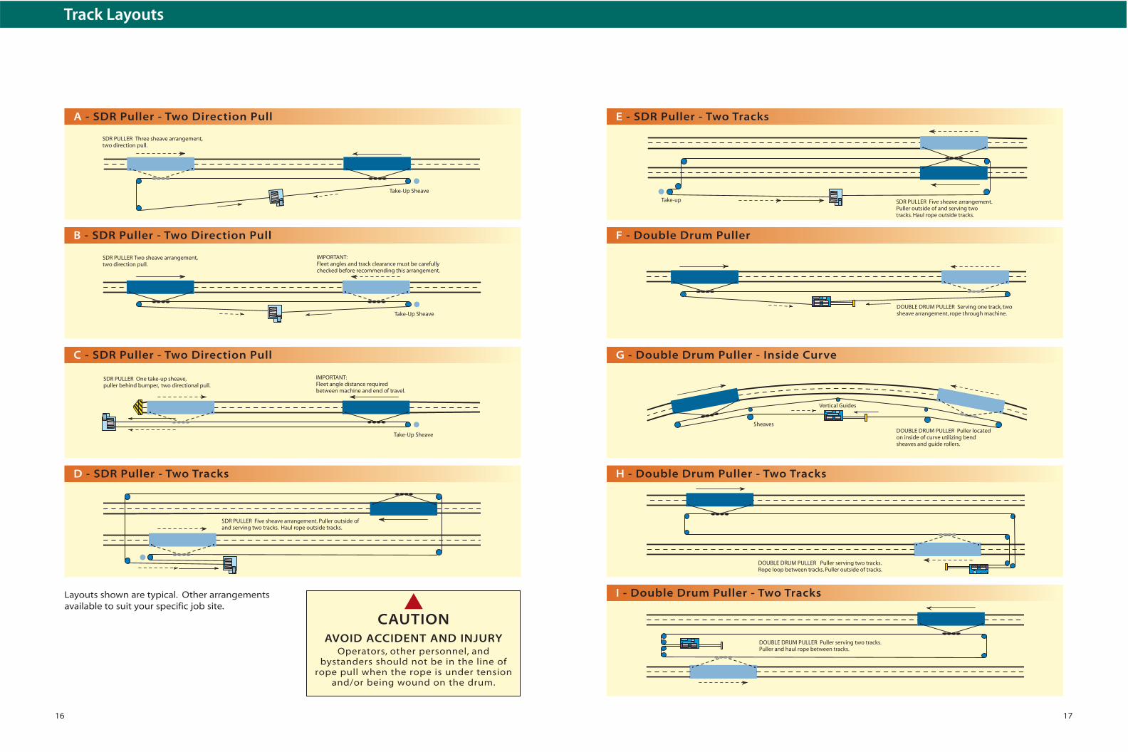
DOUBLE DRUM PULLER Puller locatedon inside of curve utilizing bendsheaves and guide rollers.
Vertical Guides
Sheaves
DOUBLE DRUM PULLER Serving one track, two sheave arrangement, rope through machine.
Take-up SDR PULLER Five sheave arrangement.Puller outside of and serving twotracks. Haul rope outside tracks.
DOUBLE DRUM PULLER Puller serving two tracks.Rope loop between tracks. Puller outside of tracks.
DOUBLE DRUM PULLER Puller serving two tracks. Puller and haul rope between tracks.
F - Double Drum Puller
E - SDR Puller - Two Tracks
G - Double Drum Puller - Inside Curve
H - Double Drum Puller - Two Tracks
I - Double Drum Puller - Two Tracks
16
Track Layouts
Take-Up Sheave
IMPORTANT:Fleet angle distance requiredbetween machine and end of travel.
SDR PULLER One take-up sheave,puller behind bumper, two directional pull.
Take-Up Sheave
SDR PULLER Three sheave arrangement,two direction pull.
Take-Up Sheave
IMPORTANT:Fleet angles and track clearance must be carefullychecked before recommending this arrangement.
SDR PULLER Two sheave arrangement,two direction pull.
SDR PULLER Five sheave arrangement. Puller outside ofand serving two tracks. Haul rope outside tracks.
A - SDR Puller - Two Direction Pull
B - SDR Puller - Two Direction Pull
C - SDR Puller - Two Direction Pull
D - SDR Puller - Two Tracks
Layouts shown are typical. Other arrangementsavailable to suit your specific job site.
AVOID ACCIDENT AND INJURYOperators, other personnel, and
bystanders should not be in the line ofrope pull when the rope is under tension
and/or being wound on the drum.
▲CAUTION
19
PUSHER DOGS CHAINGUIDE ROLLERS
8' 6" +/-
CL
TRUCK FRAME
TAKE-UP WHEEL
MAIN TRAVEL
90'-0" TYPICAL LENGTH
SPROCKETS
10' -
0''
AP
PR
OX
DRIVE ABOVEGRADE
TRACK
A
AL C
(BY OTHERS)
3'-3"
TRACK
8 "
RETURNHOUSING
SHIM AS REQ'D
TOP OF RAIL
CL23 /4"
A.A
.R. C
LEA
RA
NC
E
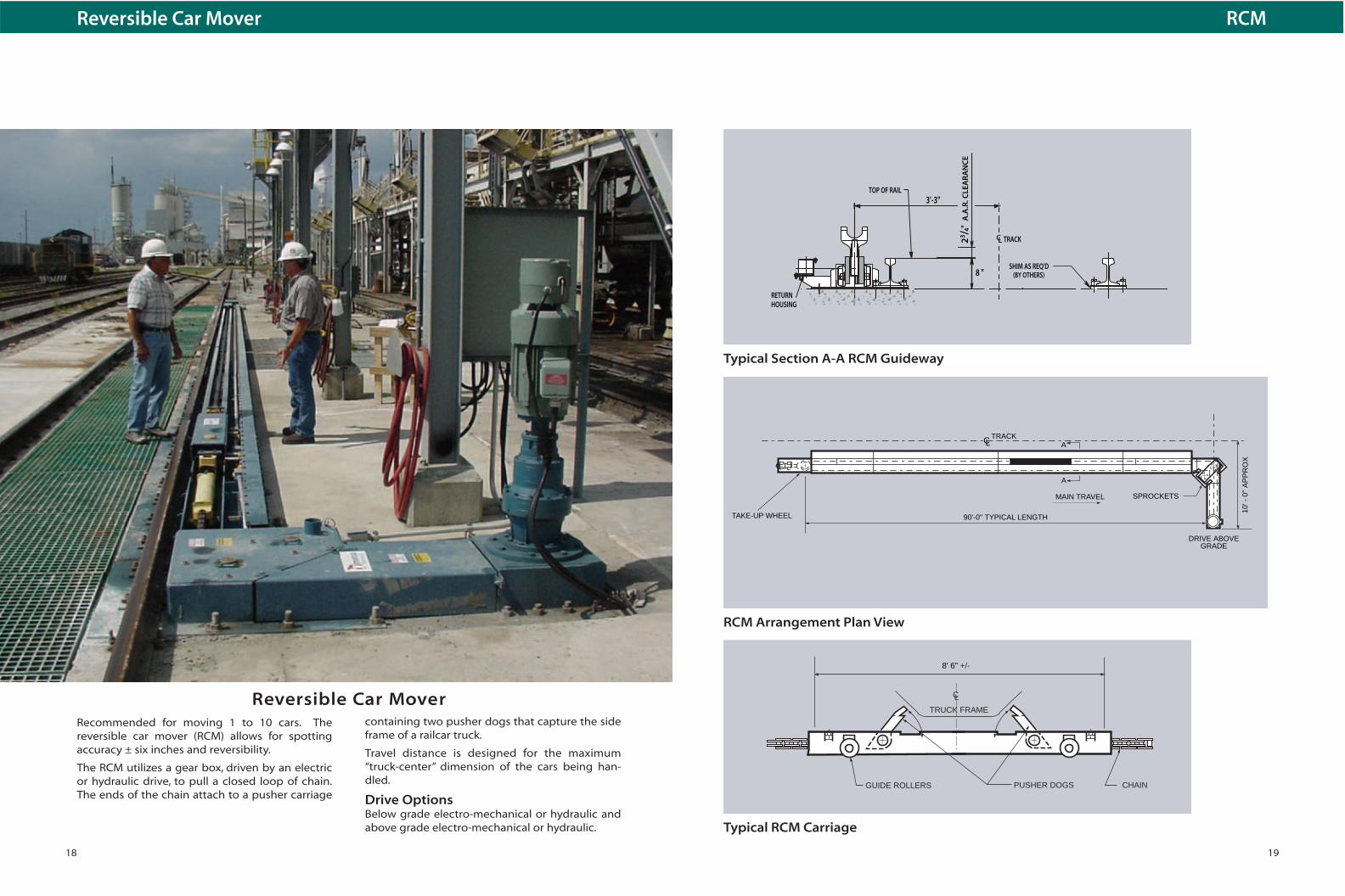
Typical Section A-A RCM Guideway
RCM Arrangement Plan View
Typical RCM Carriage
18
Reversible Car Mover
Recommended for moving 1 to 10 cars. Thereversible car mover (RCM) allows for spottingaccuracy ± six inches and reversibility.
The RCM utilizes a gear box, driven by an electricor hydraulic drive, to pull a closed loop of chain.The ends of the chain attach to a pusher carriage
Reversible Car Movercontaining two pusher dogs that capture the sideframe of a railcar truck.
Travel distance is designed for the maximum“truck-center” dimension of the cars being han-dled.
Drive OptionsBelow grade electro-mechanical or hydraulic andabove grade electro-mechanical or hydraulic.
RCM

21
One Man Control System
Six easy-to-use deadman type push buttoncontrols are provided in an oil tight enclosure.Explosion proof operator stations are available.Controls can be located at any point that providesthe operator with good visibility of the operation.
Controls include: Motor Stop, Motor Run (illumi-nated), Move Cars, Left Hand Dog Reverse, RightHand Dog Reverse and Store Dogs.
Treadle Operation
Pusher dog on side-frame of railcar truck.
PISTON
RR CAR DIRECTION
PISTON
RR CAR DIRECTION
PISTON
RR CAR DIRECTION
PISTON
PISTON
RR CAR DIRECTION
1 Cylinder retracts Pusher Dog Assembly. The Dog Operating Wheel is in the UP position andthe Pusher Dog is in the down position.
2 As the Dog Assembly retracts, the Treadle Operating Arm engages the Treadle Bar, pushingit down. The cylinder continues to retract thePusher Dog Assembly
3 As the Pusher Dog Assembly passes under the railcar truck, the truck depresses the Dog Operating Wheel. As the wheel moves DOWN,it pushes the Dog UP.
4 When the Dog clears the car truck, it is free to pop up into pushing position. As the Dogpops UP, it releases the pressure of the TreadleOperating Arm on the Treadle Bar and the Treadle Bar raises UP, activating the Sensor.
5 When the Sensor “reads” the Treadle Bar in UPposition, it sends a signal to the hydraulic valveand reverses the direction of the Hydraulic Cylinder and Dog. The Dog engages the cartruck and pushes it forward.
6 The cylinder extends its full stroke. The Dog on the opposing side of the HCM has a six inchoverlap, and will pick up the car truck on the opposite side and push the car until its cylinderhas reached its full extension. At this point, theforward Dog picks up the car and the previousDog retracts. The final Dog picks up and pushes the car.
7 The hydraulic cylinders on the HCM automati-cally reverse their direction when they reachtheir fully extended position. Each time the firstDog retracts under a car truck, it activates theStroke Selector and reverses the opposing cylinder. This sets up the cycle for the four Dogs.
Installation RecommendationsIdeal conditions for an HCM installation include 80feet of straight and level track.
Normally, the HCM installs on your existing ties.For lower throughput operations, a single sidedHCM can be a good alternate approach.Maintaining the stroke length of a double-sidedHCM, the single sided unit indexes in 13 feet incre-ments. Cycle times for one car length of travel isapproximately 21⁄2 minutes.
Custom configurations are available for site specific parameters.
20
Nolan™ Hydraulic Car MoverThe Nolan Hydraulic Car Mover (HCM) cuts costson bulk loading and unloading operations. TheNolan HCM uses dependable hydraulic power andpush button controls for one man spotting of hop-per, tank and other bulk handing railcars. Doubleacting cylinders increase cylinder life and reducemaintenance costs. Strings with up to 35 cars arepositioned within ± six inches accuracy at speedsof 25 feet per minute.
The HCM adjusts automatically to cars of variouslengths as they enter the HCM mechanism. Thispermits handling a mixture of car lengths in a sin-gle string. On many applications, the HCM can betied into a completely automated system thatadvances and loads cars without an operator.
For most applications, the 80 foot long HCMinstalls on existing rail ties. It does not requireexcavation, pouring of concrete pads, or other
costly preparations. Each HCM is custom built tomatch your application including a stroke selectormechanism to match your maximum car length,type of controls, remote control location, andother optional selections.
In use for over 20 years, the Nolan HCM has ademonstrated record of significant cost reductionin loading and unloading operations for a broadrange of industries.
Hydraulic Car Mover - Nolan HCM
Providing Dependable Service for the following:
Steel Mills, Mines, Grain Terminals and
Elevators, Electric Generating Plants,
Petro-Chemical Plants and other Bulk
Handling Industries.

23
SCAMP
Embedded radio control features 900 Mhz licensefree band and spread spectrum technology withencoded transmissions. Controls are non-PLCdependent and are range tested up to 1500 feet.
Wireless, leak-proof design, battery systemwith built-in short circuit protection. Usesindustry standard 24 VDC configurationprotected with auto blade type fuses foreasy replacement, and a 160 Ah generouspower reserve for continuous operation.
Battery Operated SCAMP
The totally electric battery operated SCAMP
■ Eliminates all hydraulics in the carriage ■ Uses electric linear cylinder actuators ■ Leak-proof design battery system ■ Employs its own battery charging system ■ Can be retrofitted to existing installations
22
OperationThe Stephens-Adamson SCAMP is designed tomove cars by locking around the axle. Thismethod eliminates the need for heavy hitch ropes.A single operator can acquire a car, position it, andreturn the carriage for the next car, all from thecontrol station. An axle counting system allowsthe car mover to run with a high degree ofautomation. Cars can be spotted within a fewinches without locking or dragging car brakes.
A SCAMP handles up to 50 railcars on level track.
SCAMP™ Automatic / Manual Railcar Positioner
Advanatages ■ Railcars can be accurately positioned ± 6
inches with a One-Way SCAMP or ± 1 inchwith a Reversible SCAMP.
■ Minimal foundation work required…no special pits or trenches needed.
■ Can be automated to meet individual customer needs.
■ “Pusher Dog” contacts railcar on or near center of axle minimizing “racking of truck”and chance of derailment.
■ Low profile design meets railroad clearances.■ Handles up to 50 railcars.■ No dedicated operator required.■ Personnel are protected, since the operator
does not handle heavy hitches, ropes,“pusher dogs” or any other part of theSCAMP carriage system.
■ Variable speed control reduces shock loading…controls acceleration and stopping(with reversible unit)…minimizes risk of damage to railcar.
■ All wire rope is enclosed or contained in wirerope propelled units.
■ Braking is controlled on grades or at any desired point.
■ Low maintenance…no locomotive, crew oroperating fuel necessary.
DriveHydrostatic drive provides smooth starts andstops while protecting the equipment from anoverload. A joy stick control allows adjustablespeed for loading or unloading requirements.Programmable controllers are used to automatethe acquisition sequence.
InstallationThe SCAMP can be installed on ties or on concreteon approximately 150 to 200 feet of straight track.Trackway can be installed over many types of scales.
Stephens-Adamson SCAMP

25
Equipment
Three types of pullers are available:Two Units Opposed –Is often the simplest approach. These units areavailable with AC motors, DC motors, variable fre-quency, flux vector or hydrostatic drives (Fig. 1).
Double Drum Closed Loop–Units make a closed circuit rope path. This type ofunit is used where rope travel ranges from 500 to1,200 feet (Fig. 2).
Single Drum Closed Loop –Is used for shorter travel or closed loops up toabout 600 feet (Fig. 3).
Breasting WinchesBreasting winches are available to keep bargespulled up next to a dock or cells.
Modern fiberglass barge covers, equipped withhatches for loading, may need breasting winchesto avoid damaging chutes (Fig. 4).
SheavesTwo types of sheaves are typically used. Theshackle type and the “fairlead” type can be provid-ed. Fairleads are used to reduce sheave wear andprovide positive control of the rope where largedirection changes or very high catenary tensionsare found. Rope manufacturers recommend aminimum sheave diameter of 20 times the ropediameter. Sheaves with too small a diameter candamage rope and reduce rope life.
Selection of rope size is quite important. Catenarytension (the tension created by hanging the ropebetween two supports) is added to the tensiongenerated by pulling barges. The tension increas-es with the square of the distance between thesupports.
Four roller fairleads used toguide wire ropes to bargesfrom breasting winches.
Flag type fairleads accom-modate changes lead angleof wire rope as barges move.
CELLS OPPOSED PULLERS
BARGE
BARGE
CELLS DOUBLE DRUM PULLER TAKE-UP
FLOATING DOCKFLOATING DOCK
BARGE BARGE
TAKE-UP STYLE 970 PULLER
DOCKFAIRLEADSHEAVES
BARGE
BREASTING WINCH
DECK-MOUNTEDFAIRLEAD SHEAVES
DOCK
figure 1
figure 2
figure 3
figure 4
24
Standard & Heavy Duty Barge Hauls
Typical ApplicationWhether your application calls for moving onebarge, or five barges, Metso Minerals can engi-neer a Stephens-Adamson barge puller to meetyour needs…from basic opposed units, to anarrangement complete with hydrostatic, DC, AC,flux vector or variable frequency drives, breastingwinches and a power take-up. These ruggedbarge pullers are engineered to stand up to therigors of the river.
Equipment selection for your project depends on anumber of factors. Like the size and number ofbarges you have to move; the river current; thetravel required; the available cells, docks or dol-phins; and the speed of operation. Even the modeof operation is important, including how manypasses will be required to load or unload.Seasonal river or pool fluctuations must also beconsidered. Working against near flood conditionsor high currents requires a very large puller.Forces on the front of the barge created by thecurrent increases exponentially with river velocity.
Computer aided application programs help ourspecialists to optimize the selection of equipmentto meet your needs based on this information.Because the barge puller sizing depends mainly
on the river current, it is important to set practicalparameters for operation under varying environ-mental conditions.
BargesToday’s “jumbo” barge is typically 35 feet wide and195 feet long. With a draft of 9 feet, the cargo canbe 1,500 tons. Empty weights vary, but usuallyrun from 350 tons to 450 tons when covers areadded. Most barges have a flat end and a rakedend. Rakes are usually 45°. It takes less force tomove the barge against the current when the rakeend is upstream.
Barge Handling
■ River current (fpm or mph)■ Rake End:
Upstream or Downstream■ Number of barges in string■ Number of full barges■ Gross weight of barge
(tons each)■ Draft full (feet)■ Terminal sheave
centers (feet)
Application Data
■ Travel required (feet)■ Operating speed (fpm)
(usually up to 30 fpm)■ Water elevation for operation:
High waterNormal poolLow waterElevation of dock or cell
Please include sketch of dockor cell layout arrangement.
26 27
Complete Systems
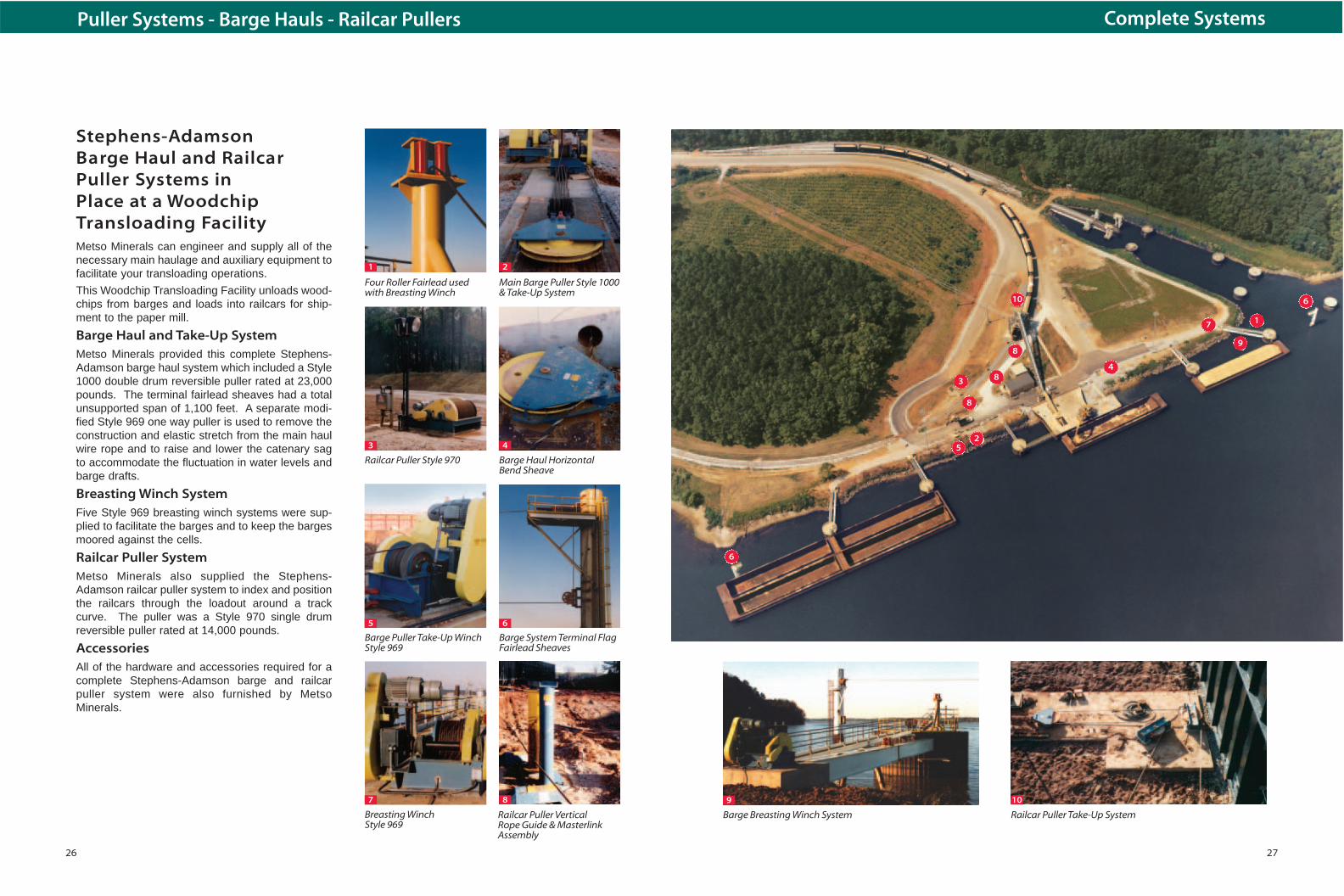
Railcar Puller Take-Up SystemBarge Breasting Winch System
9 10
1
2
4
5
6
7
8
8
8
9
10
3
Stephens-Adamson Barge Haul and RailcarPuller Systems in Place at a WoodchipTransloading FacilityMetso Minerals can engineer and supply all of thenecessary main haulage and auxiliary equipment tofacilitate your transloading operations.
This Woodchip Transloading Facility unloads wood-chips from barges and loads into railcars for ship-ment to the paper mill.
Barge Haul and Take-Up SystemMetso Minerals provided this complete Stephens-Adamson barge haul system which included a Style1000 double drum reversible puller rated at 23,000pounds. The terminal fairlead sheaves had a totalunsupported span of 1,100 feet. A separate modi-fied Style 969 one way puller is used to remove theconstruction and elastic stretch from the main haulwire rope and to raise and lower the catenary sagto accommodate the fluctuation in water levels andbarge drafts.
Breasting Winch SystemFive Style 969 breasting winch systems were sup-plied to facilitate the barges and to keep the bargesmoored against the cells.
Railcar Puller SystemMetso Minerals also supplied the Stephens-Adamson railcar puller system to index and positionthe railcars through the loadout around a trackcurve. The puller was a Style 970 single drumreversible puller rated at 14,000 pounds.
AccessoriesAll of the hardware and accessories required for acomplete Stephens-Adamson barge and railcarpuller system were also furnished by MetsoMinerals.
Puller Systems - Barge Hauls - Railcar Pullers
Barge System Terminal FlagFairlead Sheaves
6
8
Main Barge Puller Style 1000& Take-Up System
2
Barge Haul HorizontalBend Sheave
4
Barge Puller Take-Up WinchStyle 969
5
Breasting Winch Style 969
7
Four Roller Fairlead usedwith Breasting Winch
1
Railcar Puller Style 970
3
Railcar Puller Vertical Rope Guide & Masterlink Assembly
6