:^ mechaniga! behavio of r natural based...
TRANSCRIPT

: 3 a a * t ^ ^ .̂•-
L = i : ^ - i : * „ I
MechaniGa! Behavior of Natural Based Composites
Maste
VICTORIA UNIVERSITY OF TECHNOLOGY
3 0001 00555 9564

The Influence of Fiber Hybridisation on Dynamic Mechanical Behavior of Natural Based Composites
Jie Cheng
A thesis submitted to Victoria University of Technology for the degree of Master of Engineering by Research in Mechanical Engineering
2000

FTS THESIS 620.197 CHE 30001005559564 Cheng, Jie The influence of fiber hybridisation on dynamic mechanical behavior of

Declaration
The thesis contains no material which has been accepted for the award of any other degree or
diploma in any university or institution. It contains no material previously published or written by
another person, except where due reference is made in the text of the thesis.
Jie Cheng'
March 1998

A cknowledgments
There are many people who 1 would like to thank for their willing and cheerful help,
without whom 1 could not have completed this work.
My thanks to my supervisors; Dr. Mark Hodge, Dr. Ozden Turan and Dr. Benjamin Tobias
for their valuable guidance and helpful suggestions throughout the period of my candidature. I
consider myself to have been extremely lucky to have had such diligent and expert supervisors.
Sincere thanks also to Mr. Vincent Rouillard, with whom it has been a pleasure to work,
and who helped me with the operation of Instron Model 8500 Testing System.
Special thanks go to my colleagues David Ip and Vu Nguyen for their constructive advice
in fabrication and testing of composite materials, for their concern and assistance on this work.
Finally, for their encouragement, for their constant support and for their contribution, my
love and gratitude go to my wife, Qiwen Xu, and my family. It is to them that I dedicate this
thesis.

Abstract
The relatively higher costs of synthetic fibres (glass, carbon, kevlar fibre) used in fibre
reinforced composite materials make it desirable to investigate natural fibres as a source of
possible reinforcement in low-cost applications. Natural fibres are abundant and represent a
significant cost reduction compared to wholly synthetic composite materials. It is possible to
make hybrid natural and synthetic fibre reinforced composites by using fewer amoimts of
expensive reinforcements with larger amotmts of natural fibres, thereby reducing the cost of the
material.
Hybrid synthetic and natural fibre composite materials are attractive structural materials
because of natural fibres' resource and lower cost. Their advancement is a relatively yoimg and
dynamic one. Composites manufactured with these fibres have specific advantages compared
with conventional composites for low cost industry applications.
There is growing interest in the development of hybrid fibre composites, which enhances
optimal utilization of natural fibre resources. This work presents a detailed investigation of the
dynamic and static mechanical properties of hybrid natural and synthetic fibre composites
observed over a range of glass fibre and banana fibre contents.
This thesis describes the methods used in composite fabrication and material
characterization. The techniques and principles employed in the fabrication of hybrid banana

Abstract IV
fibre and glass fibre reinforced composite materials are reported. The principles of composite
design and other research relevant to hybrid fibre composite materials are critically reviewed.
Dynamic and static mechanical properties were tested imder both dry and wet conditions.
The effect of hybrid fibre contents and glass/banana fibre volume fractions has been investigated.
The moisture effect is an important aspect of this work, because natural fibres are very
hygroscopic. This work indicates the variation of dynamic and static properties in these materials
in response to water absorption.
The results indicate that banana fibre can be used as reinforcement in polyester composites
combined with glass fibre for a specific application, such as providing an inexpensive building
material. Although these hybrid composites have lower strength compared to all-glass fibre
composites, the material cost and weight are reduced, thereby enhancing the usefulness of these
materials in developing countries and regions requiring rapid erection of dwellings, such as areas
affected by natural disasters. The use of low modulus and low cost matrix materials such as
polyester and the addition of natural fibres produces hybrid composites, maintaining flexibility,
lightness and ease of fabrication of complicated shapes with reasonable economy.
Based on the investigations contained herein, it is expected that these composites could
find suitable applications in the following areas:
• Low cost housing,
• Emergency shelter materials following natural disasters,
• Packaging for tiansportation purposes,
• Manufacturing of consumable goods.

Table of Contents
Declaration of Originality /
Acknowledgements //
Abstract Hi
Contents v
List of Tables viii
List of Figures ix
Chapter 1 Introductory Remarks 1
1.1 Background Information to the Investigation 1
1.2 Scopeof The Present Work 4
1.3 Layout of Thesis 5
Chapter 2 Literature Review 7
2.1 Structure and Properties of Fibres 7
2.1.1 Banana Fibre 8
2.1.1.1 Composition and Structure of the Banana Fibre 9
2.1.1.2 Physical and Mechanical Properties
ofthe Banana Fibre 10
2.1.2 GlassFibre 13
2.1.2.1 Composition of Glass Fibre 14
2.1.2.2 Common Forms of Glass Fibre 14

Contents VI
2.1.2.3 General Properties of Glass Fibres.... 17
2.2 Fibre Reinforced Composite Materials 17
2.2.1 Natural Fibre Composites 22
2.2.2 Hybrid Fibre Composites 25
2.2.3 Short Fibre Composites 27
2.3 Composites Manufacture 28
2.3.1 Hand Lay-up Process 30
2.4 Composites Testing 31
2.4.1 Dynamic Mechanical Analysis 32
2.4.2 Static Flexure Testing 34
Chapter 3 Material Fabrication and Experimental Methods 36
3.1 Materials 36
3.1.1 Banana Fibre 36
3.1.2 GlassFibre 37
3.1.3 Matrix 37
3.2 Composition of Hybrid Fibre Composites 40
3.2.1 Rule of Mixtures 40
3.2.2 Constituents of Hybrid Fibre Composite Laminae 42
3.3 Fabrication of Banana/Glass Polyester Composite Laminae 44
3.3.1 Fabrication Facility 44
3.3.2 Fabrication Procedures 45
3.4 Specimen testing 47
3.4.1 Water Absorption 47
3.4.2 DMATesting 48

Contents 17/
3.4.2.1 Facility 48
3.4.2.2 Sample Preparation 48
3.4.2.3 Temperature Scan Mode 49
3.4.3 Static Flexure Testing 49
Chapter 4 Results and Discussion 51
4.1 Dynamic Mecharucal Analysis 51
4.1.1 Flexural Storage Modulus 51
4.1.2 Loss Tangent 60
4.2 Static Mechanical Properties 70
Chapters Conclusions 80
Chapter 6 Recommendations for Future Work 83
References 85

List of Tables
Table 2.1 Major chemical constituents ofthe banana fibre 10
Table 2.2 Physical properties of banana fibres 11
Table 2.3 Mechanical properties of banana fibres 13
Table 2.4 Typical chemical composhion of E-glass and S-glass 14
Table 2.5 Typical properties of E-glass and S-glass 17
Table 2.6 The properties of banana fibre-reinforced composites 24
Table 3.1 The composition of 10wt% hybrid fibre composites 43
Table 3.2 The composition of 25wt% hybrid fibre composites 43
Table 3.3 The composition of 40wt% hybrid fibre composites 44
Table 3.4 Water absorption of hybrid composites 47
Table 4.1 Characteristics of 10% hybrid fibre composites 56
Table 4.2 Characteristics of 25% hybrid fibre composites 57
Table 4.3 Characteristics of 40% hybrid fibre composites 57
Table 4.4 Comparison of Tg and the rate of loss tangent variation between dry and wet condition for 1 Q% hybrid composites 65
Table 4.5 Comparison of Tg and the rate of loss tangent variation between dry and wet condition for 25% hybrid composites 65
Table 4.6 Comparison of Tg and the rate of loss tangent variation between Dry and wet condition for 40% hybrid composites 66
Table 4.4 Static mechanical properties of hybrid composites 70

List of Figures
Figure2.1 The classification of fibres 8
Figure 2.2 Stress-strain relationship of banana fibres 11
Figure 2.3 Stress-strain curves of other natural fibres 12
Figure2.4 The common forms of glass fibres 16
Figure 2.5 The classification of fibre reinforced composite materials 21
Figure 2.6 The schematic for types of hybrid fibre composites 26
Figure 2.7 Schematic illustration of 3-point bending test 35
Figure3.1 10mm long banana fibres 37
Figure 3.2 Unsaturated polyester molecule 38
Figure 3.3 Four stages of setting action of the resin 39
Figure 3.4 Cross-sectional schematic view of lay-up sequences of glass and
Banana fibre in a polyester matrix 42
Figure 3.5 Schematic of composite materials pressed mould 45
Figure 3.6 Three-point bending dimensions 48
Figure 3.7 The Instron Model 8500 plus testing system 50
Figtue 4.1 The variation in flexiual storage modulus with temperature for 10% hybrid composites (dry condition) 52 Figure 4.2 The variation in flexural storage modulus with temperature for 25% hybrid composites (dry condition) 53
Figure 4.3 The variation in flexural storage modulus with temperatiue for 40% hybrid composites (dry condition) 53

List of figures X
Figure 4.4 The variation in flexural storage modulus with temperature for 10% hybrid composites (wet condition) 54
Figure 4.5 The variation in flexural storage modulus with temperature for 25% hybrid composites (wet condition) 55
Figure 4.6 The variation in flexural storage modulus with temperature for 40%) hybrid composites (wet condition) 55
Figure 4.7 The variation in loss tangent with temperature for 10% hybrid Fibre composites (dry condition) 61
Figure 4.8 The variation in loss tangent with temperature for 25% hybrid Fibre composites (dry condition) 62
Figure 4.9 The variation in loss tangent with temperature for 40% hybrid Fibre composites (dry condition) 62
Figure 4.10 The variation in loss tangent with temperature for 10% hybrid Fibre composites (wet condition) 63
Figure 4.11 The variation in loss tangent with temperature for 25% hybrid Fibre composites (wet condition) 64
Figure 4.12 The variation in loss tangent with temperature for 40% hybrid
Fibre composites (wet condition) 64
Figure 4.13 Tg vs banana fibre volume fraction (10%) hybrid fibres) 66
Figure 4.14 Tg vs banana fibre volume fraction (25%) hybrid fibres) 67
Figure 4.15 Tg vs banana fibre volume fraction (40%) hybrid fibres) 67
Figure 4.16 The flexural strength vs banana fibre voliune fraction (10%o hybrid fibres) 71 Figure 4.17 The flexural strength vs banana fibre volume fraction (25% hybrid fibres) 72
Figiue 4.18 The flexural strength vs banana fibre volume fraction (40%) hybrid fibres) 72
Figure 4.19 The flexural modulus vs banana fibre volume fraction (10%» hybrid fibres) 73
Figure 4.20 The flexural modulus vs banana fibre volume fraction (25%) hybrid fibres) 73

List of figures ^
Figure 4.21 The flexural modulus vs banana fibre volume fraction (40%) .hybrid fibres) 74
Figure 4.22 Water absorption vs banana fibre voliune fraction (10% hybrid fibres) 74
Figure 4.23 Water absorption vs banana fibre voliune fraction (25%) hybrid fibres) 75
Figure 4.24 Water absorption vs banana fibre volume fraction (40%) hybrid fibres) 75
Figure 4.25 Load deflection curve for 10%) hybrid composites(dry Condition) 77
Figure 4.26 Load deflection curve for 25%) hybrid composites(dry Condition) 77
Figure 4.27 Load deflection curve for 40% hybrid composites(dry Condition) 78
Figure 4.28 Load deflection curve for 10%) hybrid composites(wet Condition) 78
Figure 4.29 Load deflection curve for 25%) hybrid composites(wet Condition) 79
Figure 4.30 Load deflection curve for 40%) hybrid composites(wet Condition) 79

Chapter 1
Introductory Remarks
1.1 BACKGROUND INFORMATION TO THE INVESTIGATION
Fibres probably represent the most important class of reinforcement for composite
materials, due to their ability to transfer strength to matrix materials and greatly influence the
properties of composites. Many types of fibres are combined with metal, resin and ceramic
matrices to form useful fibre reinforced composite materials. Fibre reinforced composites are
produced from a wide range of constituents and have evoked a lot of interest among engineers
concerned with various applications such as aerospace and automotive.
Fibres are usually classified as either natural or synthetic fibres. Natural fibres are further
divided into vegetable, animal, or mineral origin and exist in reasonably large quantities all over
the world. In particular, they are abundantly available in developing countries, but are not usually
optimally utilized. Due to their relative abundance and ease of handling and processing, natural
fibres show considerable potential as a valuable source of raw material for use as reinforcement
for low-cost composite materials in developing countries and elsewhere throughout the world.

Chapter 1 Introductory Remarks
Currently, there is growing interest in the development of new materials, particular!)
renewable resources that facilitate utilization of natural materials. Natural fibres such as bamboo,
jute, banana, abaca, coir and sisal belong to this category. Although natural fibres generally have
poor mechanical properties compared with the synthetic fibres currently available, they have die
advantages of low density, low cost and low energy demand during manufacture.
Natural fibres have been employed in various applications and have been used in the
cordage industry for a long time. Natural fibre reinforced cement composite materials have also
been made for low cost construction materials. Al-Qureshi (1997) presented the development and
manufacture of automotive body skins of jute fabric reinforced composite, and hybrid composites
made from jute/fibre glass composite panels.
According to American Society for Testing Materials (ASTM) standard D123-52, banana
fibre is classified as leaf fibre of natural vegetable fibre. Actually, it has also been used for
composite materials and packaging materials as a valuable source of raw material. Satyanarayana
et al. (1990) reported that banana fibres incorporated in a low-modulus matrix such as polyester
would yield materials with properties adequate for incorporation into specialized building
construction materials.
Glass fibre is a typical synthetic inorganic fibre whose wide use as reinforcement in
applications ranging from fishing rods to storage tanks and aircraft parts is well knovm. At
present, the most important grades of glass are:
1. E-glass, named for its elecfrical properties. E-glass has a low alkali content and is the
most common glass fibre on the market, as well as being the most widely used in the
construction industry. E-glass is now widely used with polyester and epoxy resins for
fibre reinforced composites.

Chapter 1 Introductory Remarks 3
2. S-glass, a stronger and stiffer fibre than E-glass, was originally developed for militar}'
applications. It is not widely used outside the military and other related specialty
industries (e.g. aviation, automotive) because of its higher cost.
3. R-glass, a civil version ofthe S-glass fibre, is used for high technology application.
4. C-glass is a special mixture used for chemical resistance, mainly against acid attack.
Hybrid fibre reinforced composites are attractive structural materials and their
advancement is a relatively young and dynamic one. Hybrid fibre composites contain more than
one class of fibre. Fibre hybridization presents new opportunities for tailoring the composite
material to specific cost-effective applications and achieving properties that cannot be realized in
one single class of fibre reinforced composites. In the development of hybrid fibre reinforced
composite materials, one ofthe major problems that needs to be addressed is reduction in cost of
expensive composites with reinforcement by incorporating a proportion of cheaper fibre. The use
of a low cost matrix material such as polyester, and the hybridization of natural fibres and
synthetic fibres produce hybrid fibre reinforced composites with appreciable lightness and ease of
fabrication of complicated shapes. The hybrid composites have significant economical
advantages over wholly synthetic composite materials.
Fibre-reinforced composite materials are being increasingly employed to manufacture
structural components which are designed to be used successfully in dynamic environments under
various temperatures in many diverse industries, such as the aerospace, transportation and
sporting goods industries. As these engineering applications further diversify, the necessity for
experimental data and analysis of the proposed design methodologies becomes more important.
This is especially so when composite materials are subjected to dynamic mechanical loading

Chapter I Introductory Remarks
under changing ambient conditions. When the temperature and moisture change, so does the
dynamic mechanical behavior of the structural component fabricated by a composite material.
The dynamic mechanical properties have a major influence on the response ofthe material and the
structural integrity ofthe component.
1.2 SCOPE OF THE PRESENT WORK
In this study, banana fibres are used in conjunction with glass fibres in a polyester resin
matrix to produce a series of hybrid fibre-reinforced composite materials. As the hybrid of natural
and synthetic fibres, a reinforced composite material has been developed and characterized.
Through the use of a hybrid natural/synthetic fibre system, it is possible to achieve significant
savings in terms of weight and cost while improving mechanical properties for a specific
application such as cheap building material in developing tropical countries.
The main aim of this study has been to develop and characterize a hybrid natural and
synthetic fibre reinforcement composite lamina. The specific objectives are as follows:
1. To develop a design procedure to manufacture hybrid natural and synthetic fibre
composites.
2. To fabricate laboratory scale hybrid fibre composite laminates with random fibre
orientation.
3. To determine the bulk effect of water absorption in each laminae group.
4. To investigate possible mechanical behavior in both dry and wet conditions under
time/temperature dependent fimctions as predicted by dynamic mechanical analysis.

Chapter 1 Introductory Remarks
5. To investigate static strength and thereby determine the rigidity of hybrid fibre
composite laminae.
6. To monitor the influence of glass fibre and banana fibre volume fraction on the
properties of laminae.
1.3 LAYOUT OF THESIS
It is the intention of this work to describe the properties of banana fibres, glass fibres and
fibre reinforced composite materials, the methods of manufacturing hybrid banana and glass fibre
reinforced composite materials, and the dynamic mechanical properties of these hybrid composite
materials.
The scientific literature on fibre reinforced composite materials is reviewed in Chapter 2,
including an introduction to current applications of banana fibre and glass fibre reinforced
composites. An overview on the aspects of composite manufacture and composite testing is also
presented.
Chapter 3 focuses on the fabrication and experimentation of banana fibre and glass fibre
hybrid composites. A design procedure is developed to manufacture different fibre volume
fractions. Water absorption is also considered due to moisture absorption encountered in tropical
regions. The composite experimental investigations are carried out under both dry and wet
conditions.
The dynamic mechanical analysis with 10%), 25%) and 40%) hybrid fibre content is given

Chapter 1 Introductory Remarks
in Chapter 4. These data illustrate the variation in flexural storage modulus and loss tangent of
hybrid composites with temperature in both dry and wet conditions. The effect of hybrid fibre
contents and banana and glass fibre volume fractions is presented. With water absorption, it has
been found that the effects of interfacial bond strength between fibres and matrix dominates over
the gain in fibre properties. The static mechanical properties are also included in Chapter 4.
Conclusions are drawn and recommendations are made for future work in Chapter 5 and
Chapter 6, respectively.

Chapter 2
Literature Review
lA STRUCTURE AND PROPERTIES OF FIBRES
Fibres are the major constituent in a fibre - reinforced composite material in terms of
volume fraction and load-bearing capacity. In structural applications, fibres occupy large volume
fractions in a composite laminate and share the major portion ofthe load on a composite structure.
According to commercial and domestic use, fibres are broadly classified as natural fibres and
synthetic (man-made) fibres. Natural fibres are plant, animal or mineral products. It is interesting
to note that natural fibres such as jute, coir, banana, sisal, etc, are abundantly available in
developing countries like India, Sri Lanka and some of the African and Southeast Asian countries.
Traditionally, these fibres are used in a conventional manner for the production of yam, ropes,
mats and matting, as well as in making pattern articles like wall hangings, table mats, handbags
and purses. Fibres such as cotton, banana and pineapple are also used in making cloth in addition
to being used in the paper industry.
In the last fifty years, however, synthetic fibres, the macromolecular structure of which is
made up of relatively simple compounds, rapidly found industrial uses and challenged natural

Chapter 2 Literature Review 8
fibres. A whole new range of synthetic fibres has been developed. The classification of fibres is
shown in Figure 2.1.
natural fibre
vegetable origin
- bast fibres leaf fibres
— seed fibres - grass
animal origin
— wool hair —silk or other
filaments
fibre
mineral origin
— asbestos —wollastonite
man - made fibre
natural polymers
- cellulose —cellulose esters — protein fibres —miscellaneous
synthetic polymers
Figure 2.1 The classification of fibres (after Fordos 1988).
2.1.1 BANANA FIBRE
Banana plants are now found in most tropical regions. In Australia, they are extensively
grovm in Queensland and northern New South Wales. As indicated by Mickels (1990), the
banana plant has a tree-like appearance and a trunk-like stalk, although h contains no woody
material and can grow from 3.0 m to 9.0 m. The stalk, which ranges in diameter from 200 mm
to 370 mm, consists of layers of overlapping leafstalk surrounding a hollow core. At the end of
each stalk is a dark-green oblong leaf, measuring about 3600 mm by 600 mm. The stalk
contains long multi-celled fibres extending length-wise through the pulpy tissues of long leaves
or leaf-stems.

Chapter 2 Literature Review
Banana fibres are obtained from the pseudo stem of the banana plant. The pseudo stem is
called stalk, and is surrounded and supported by leaf sheaths which contain many fibres. A
normal stalk is 1.8 m to 3.0 w long and 0.2 m to 0.3 m wide, and each leaf contains fibres in the
outer layers. The processes of obtaining banana fibre typically involve manual or mechanical
scraping.
2.1.1.1 Composition and structure ofthe banana fibre
According to the American Society for Testing Materials (ASTM) Standard D123-52,
banana fibres are still classified as leaf fibre of natural vegetable fibre, even though they are
extracted from pseudo stem. Under close examination, the banana stalk reveals fibres extending
longitudinally along the entire length ofthe leaf, reinforcing the leaf structure and keeping it rigid.
The fibres are embedded in the pulp tissue of the leaf and are distributed throughout the leaf cross
section.
According to Himmelfarb (1957), Banana fibres are multiple-celled structures. The long
fibre is composed of a bundle of fine hair-like fibres (fibrils) cemented together with the natural
gummy materials of the plant tissue. Each fibril, in turn, is made up of a number of cells, which
may appear as tubes of irregular polygonal cross section with enclosed pointed ends when greatly
magnified. These cells lie side-by-side with overlapping ends and are cemented together to make
up the long fibril. A hollow canal in the center ofthe cell is called the lumen, which is the space
previously occupied by the protoplasmic material forming the cell. The cell represents the
ultimate in division of the fibre. Four types of cells have been found, namely, xylem, phloem,
Sclerenchyma and psu'enchyma arranged in a particular fashion (Kulkarni et al. 1983).
Chapter 2 Literature Review 10
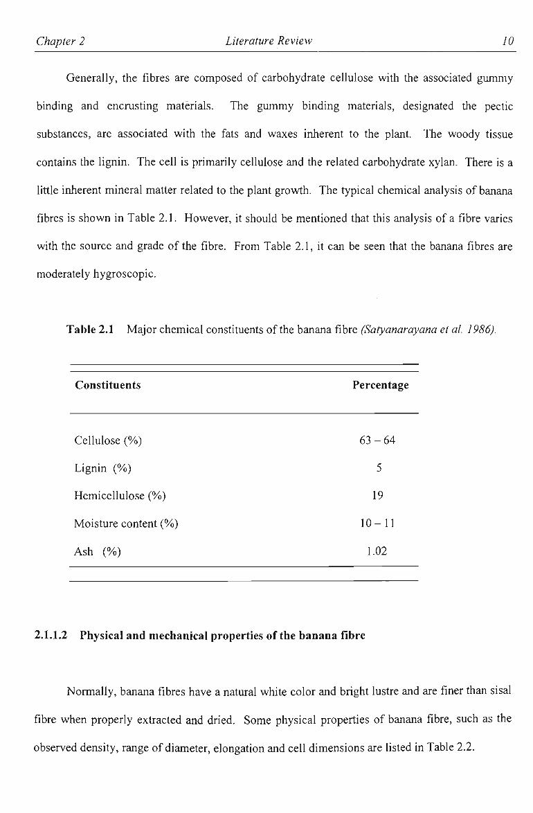
Generally, the fibres are composed of carbohydrate cellulose with the associated gummy
binding and encrusting materials. The gummy binding materials, designated the pectic
substances, are associated with the fats and waxes inherent to the plant. The woody tissue
contains the lignin. The cell is primarily cellulose and the related carbohydrate xylan. There is a
little inherent mineral matter related to the plant growth. The typical chemical analysis of banana
fibres is shown in Table 2.1. However, it should be mentioned that this analysis of a fibre varies
with the source and grade ofthe fibre. From Table 2.1, it can be seen that the banana fibres are
moderately hygroscopic.
Table 2.1 Major chemical constituents ofthe banana fibre (Satyanarayana et al. 1986).
Constituents Percentage
Cellulose (%) 63 - 64
Lignin (%) 5
Hemicellulose (%) 19
Moisture content (%) 10-11
Ash (%) 1.02
2.1.1.2 Physical and mechanical properties ofthe banana fibre
Normally, banana fibres have a natural white color and bright lustre and are finer than sisal
fibre when properly exfracted and dried. Some physical properties of banana fibre, such as the
observed density, range of diameter, elongation and cell dimensions are listed in Table 2.2.

Chapter 2 Literature Review II
Table 2.2 Physical properties of banana fibres (Satyanarayana et al. 1986).
Properties
Density (kg/m^)
Elongation (%>)
Apparent density
Cell width or diameter (jam)
Cell length (mm)
Cell length to diameter ratio
Size of cell wall (pm)
Fibre porosity (%))
1350
1.8-3.5
0.62
12-30
2.0-4.8
150
1.25
35-53
Figure 2.2, from Kulkarni et al (1983) shows a typical stress-strain curve for banana
fibre. Figure 2.3, from Satyanarayana et ai (1990) shows stress-strain curves for some of the
natural fibres compared whh banana fibre.
I 2 % S T R A I N •
Figure 2.2 Stress-strain relationship of banana fibre (Kulkarni et al. 1983).

Chapter 2 Literature Review 12
0.01
PINEAPPLE
002 003 004 005 038 039 STRAIN
Figure 2.3 Stress - strain curves of othtr natmaXfvhxQS (Satyanarayana et al. 1990).
Satyanarayana et al. (1984) reported that the strength of banana fibre varies along the
stem. Fibres in the lowest portions of the stalk are strongest and the stiength decreases with
increasing height. Also the fibre, if aged for a short period, gains strength to the extent of 1.05-
1.10 times the original strength. When dried at 100 C for 2 days or to 70 C for 20 days, the fibres
exhibited a decrease in stiffness and strength, along with evidence of mechanical embrittlement as
the water content in the fibres decreased. Although somewhat counter-intuitive, this data
indicates that the hygroscopic nature of the banana fibre is critical to its mechanical performance,
as the fibre is stiffened to some degree by water absorption. X-ray analysis shows that banana
fibre has a high degree of crystallinity with good alignment of crystallites parallel to the fibre axis.
It is proposed that increased water content may enhance molecular mobility to the point where
some molecular alignment is possible in the amorphous regions of the fibres, thereby enhancing

Chapter 2 Literature Review 13
the physical properties as observed. Some ofthe mechanical properties of banana fibre are shown
in Table 2.3.
Table 2.3 Mechanical properties of banana fibres (Satyanarayana et al. 1986).
Initial modulus (GN/m^) 20-51
Ultimate tensile strength (MPa) 520-750
Torsional rigidity ( G N W ) 0.3-1.2
Flexural rigidity (N/m ) 2-5
2.1.2 GLASS FIBRE
Glass fibres are probably the most common of all reinforcing fibres for polymeric matrix
composites. The major type of glass fibre is E-glass, which is a borosilicate glass with a little
alkali present in its composition. E-glass represents one of the lowest costs of all commercially
available reinforcing synthetic fibres, which is the major reason for its widespread use in the fibre-
reinforced composites industry.
In general, the principal advantages of glass fibres include high tensile strength, high
chemical resistance and good insulating characteristics. On the other hand, the disadvantages are
low modulus compared to other high performance fibres such as carbon and kevlar fibres,
relatively high specific gravity (among the commercial fibres), high cost (compared to natural
fibres), sensitivity to abrasion with handling which frequently decreases tensile strength, low
fatigue resistance and high hardness.

Chapter 2 Literature Review 14
lA.lA The composition of glass fibre
Glass fibres are amorphous (noncrystalline) materials. Their mtemal structure consists of a
three dimensional long network of silicon, oxygen, and other atoms arranged in a random fashion.
They have no distinctive micro structure. The principal constituent in all glass fibres is silica
(SiOi). Other oxides, such as B2O3 and AI2O3, are added to modify the network structure of Si02
as well as to improve its workability (Matthews and Rowlings 1994).
The E-glass is named because of its electrical properties. It is based on the eutectic in the
ternary system CaO - AI2O3 - Si02 with some B2O3 substituting for Si02 and some MgO for CaO.
The main chemical composition of E-glass and S-glass is shown in Table 2.4.
Table 2.4 Typical chemical composition of E-glass and S-glass (Matthews and Rowlings 1994).
Glass fibre type Oxides in weight fraction (%)
Si02 AI2O3 CaO B2O3 MgO
E-glass 54 14 18 9 5
S-glass 65 25 - - 10
2.1.2.2 Common forms of glass fibres
The basic commercial form of continuous glass fibres is a strand, or collection of
individual fibres also known as a tow. The strands may be brought together to form an untwisted
bundle of fibres called a roving. Both strands and roving can be woven into a variety of cloths.

Chapter 2 Literature Review 15
The roving may be chopped into strands or into strand mats, which form random arrays of fibres.
The common forms of gleiss fibres include continuous strand roving, chopped strands, chopped
strand mat, woven roving and woven roving mat (Mallick 1988). Figure 2.4 shows the common
forms of glass fibres.
Chopped strands are formed by cutting continuous strands into short lengths. Their length
ranges from 3.2 mm to 12.7 mm. Chopped strand mat is manufactured from chopped strands,
which are bonded together in a randomly oriented two-dimensional manner. The strand mat is
normally 50mm in length. This type of reinforcement is considerably cheaper than woven fabric
when measured on a weight basis and is typically used as a reinforcing material in a laminate by
itself or in conjunction with a woven fabric. Chopped strands are often used in injection molding
operations.
Glass fibres are also available in woven form. Woven roving is a coarse fabric and used in
moulding and laminates to produce highly directional strength characteristics. A layer of woven
roving is sometimes bonded with a layer of chopped strand mat to produce a woven roving mat
(Mallick 1988). The woven forms are suitable for hand lay-up moldings.
All forms of glass fibre must have a surface treatment called a "sizing", which enhances the
surface properties of the glass, allowing them to bond to a matrix material in composite
applications and allowing relatively easy movement across one another without adverse
mechanical damage or other adverse effects, such as static charge buildup and entanglements. It
is very important to choose the correct sizing from both processing and mechanical performance
points of view.

Chapter 2 Literature Review 16
» »
?.** '̂ ̂ ̂ •̂ \v
\. <-
^ : V'
\ ' wV> •* \ ^
A^
L\^
Continuous strand ravine Woven roving mat
Chopped strands chopped strand mat
Woven roving
Figure 2.4: The common forms of glass fibres (Mallick 1988).

Chapter 2 Literature Review
2.1.2.3 General properties of glass fibres
Glass fibre properties are not strongly dependent on the chemical composition of fibre.
The mechanical properties are isotropic. Processing parameters during fibre forming have a
significant effect on fibre properties. Furthermore, fibres of the same composition and same
diameter but made under different forming conditions show differences in properties. Table 2.5
shows some properties ofthe E-glass fibre and S-glass fibre.
Table 2.5 Typical properties of E-glass and S-glass (Potter 1997 and Mallick 1988).
Properties E-glass S-glass
Diameter (|im) 7 7
Specific gravity 2.54 2.49
Tensile modulus (GPa) 70 88
Tensile strength (GPa) 1.7 4.6
Strain to failure (%)) 2.2 5.2
Density (g/cm^) 2.56 2.49
2.2 FIBRE REINFORCED COMPOSITE MATERIALS
In engineering practice, the modem composite materials have had a significant impact on
the technology of design and construction. It is a common principle that two or more components
may be combined together to be tailor-made advanced composite materials, which are lighter,
Chapter 2 Literature Review 18
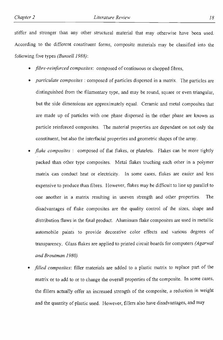
stiffer and stronger than any other structural material that may otherwise have been used.
According to the different constituent forms, composite materials may be classified into the
following five types (Bunsell 1988):
• fibre-reinforced composites: composed of continuous or chopped fibres,
• particulate composites : composed of particles dispersed in a matrix. The particles are
distinguished from the filamentary type, and may be round, square or even triangular,
but the side dimensions are approximately equal. Ceramic and metal composites that
are made up of particles with one phase dispersed in the other phase are known as
particle reinforced composites. The material properties are dependant on not only the
constituent, but also the interfacial properties and geometric shapes ofthe array.
• flake composites : composed of flat flakes, or platelets. Flakes can be more tightly
packed than other type composites. Metal flakes touching each other in a polymer
matrix can conduct heat or electricity. In some cases, flakes are easier and less
expensive to produce than fibres. However, flakes may be difficult to line up parallel to
one another in a matrix resulting in uneven strength and other properties. The
disadvantages of flake composites are the quality control of the sizes, shape and
distribution flaws in the final product. Aluminum flake composites are used in metallic
automobile paints to provide decorative color effects and various degrees of
fransparency. Glass flakes are applied to printed circmt boards for computers (Agarwal
and Broutman 1980).
• filled composites: filler materials are added to a plastic matrix to replace part of the
matrix or to add to or to change the overall properties ofthe composite. In some cases,
the fillers actually offer an increased strength of the composite, a reduction in weight
and the quantity of plastic used. However, fillers also have disadvantages, and may

Chapter 2 Literature Review 19
limit the method of fabrication or inhibit curing of certain resins.
• laminar composites: composed of two or more layers or lamina constituents held
together by the matrix binder. There are as many possible laminar composites as there
are combinations of materials, such as metal/metal, metal/plastic, metal/ceramic
laminates etc. At present, the greatest emphasis is on structural laminates or laminates
with useful mechanical properties (ASM 1990).
Within the above classification of composites, one of the most important of the composite
material types cited from an application point of view is fibre-reinforced composites. Although
fibre-reinforced composites have been used only for a relatively short period of time among the
modem stmctural materials, there has been a dramatic advancement in the technology of fibre
composites. Fibre composites have evoked the most interest among engineers concemed with
structural applications. It has been pointed out by Tobias (1987), that synthetic fibres play an
important role in the development of new composite materials.
In fibre-reinforced materials, high strength fibres are surrounded by a relatively weak
matrix. The fimctions of the matiix are to bond the fibres together, to transfer the load from one
fibre to another and to protect them from damage. Thus, the fracture toughness properties of fibre
reinforced materials are enormously affected by interfacial bonding between matrix and fibres.
Fibre composites which have a weak interface have low strength and stiffness but have high
resistance to fracture. On the other hand, fibre composites which have strong interface have high
strength and stiffness but are very brittle. The most important fibre parameters are diameter,
length, volume fraction and aligrmient.
Chapter 2 Literature Review 20
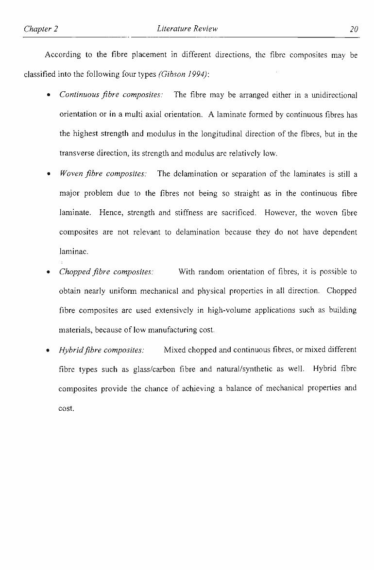
According to the fibre placement in different dhections, the fibre composites may be
classified into the following four types (Gibson 1994):
• Continuous fibre composites: The fibre may be arranged either in a unidirectional
orientation or in a multi axial orientation. A laminate formed by continuous fibres has
the highest strength and modulus in the longitudinal direction of the fibres, but in the
transverse direction, its strength and modulus are relatively low.
• Woven fibre composites: The delamination or separation of the laminates is still a
major problem due to the fibres not being so straight as in the continuous fibre
laminate. Hence, strength and stiffness are sacrificed. However, the woven fibre
composites are not relevant to delamination because they do not have dependent
laminae.
• Chopped fibre composites: With random orientation of fibres, it is possible to
obtain nearly uniform mechanical and physical properties in all direction. Chopped
fibre composites are used extensively in high-volume applications such as building
materials, because of low manufacturing cost.
• Hybrid fibre composites: Mixed chopped and continuous fibres, or mixed different
fibre types such as glass/carbon fibre and natural/synthetic as well. Hybrid fibre
composites provide the chance of achieving a balance of mechanical properties and
cost.

Chapter 2 Literature Review 21
Fibre composite types are shown schematically in Figure 2.5 below.
Continuous fibre composite Woven fibre composite
Chopped fibre composite Hybrid composite
Figure 2.5 The classification of fibre reinforced composite materials (Gibson 1994).
The commercial and industrial applications of fibre composites are varied and widespread.
A significant stmctural application is in the field of commercial and military aircraft. Composite
materials reinforced with carbon fibre, either alone or in hybridization with kevlar fibres, have
become the primary material in many wing and fuselage components in aerospace applications.
The aim of this is to improve performance while reducing weight.
The principal advantage of usmg fibre-reinforced composites is weight reduction. For
instance, in the field of sporting goods applications, weight reduction achieved by substituting
carbon fibre-reinforced epoxy for metal has led to higher speeds and improved maneuvering in

Chapter 2 Literature Review 22
competition, such as bicycle or canoe racing. Weight reduction in the golf club shaft results in a
faster swing as well as a longer drive (Cahn 1990).
Fibre-reinforced composite materials also have found wide use in the automotive industry.
Great emphasis is being placed on the development of light weight automobiles, fuel economy,
and cost-effectiveness issues. The high cost of carbon or kevlar fibre reinforced epoxies have
paved the way for lower cost E-glass fibre reinforced polyesters or natural fibre-reinforced
polyesters in key automotive applications. In marine applications, glass fibre-reinforced polyester
laminates are used in areas such as hull, deck, mast, bulkheads and frames. Weight reductions
made possible by using composite materials have increased boats' cmising speeds,
maneuverability and fuel efficiency.
2.2.1 N A T U R A L FIBRE COMPOSITES
The history of natural fibre composites can be dated back thousands of years. The ancient
Chinese, Egyptians and Israelites all made bricks by mixing straw with clay. Bamboo used so
often in structures by the Chinese is in fact a typical fibrous composite material. The principle of
natural composite materials can be found in numerous naturally occurring substances. Wood is an
interesting example of a natural fibre composite composed primarily of cellulose fibre chains
bonded togetiier witii lignin matrix. The bond between the fibres and lignin is exceedingly strong.
The high sfrengtii and stif&iess of wood, along witii its well-known versatility and attractiveness
provide a ready indication of the effectiveness of natural fibre reinforced composite materials.
Bone is anotiier type of natural composite material composed primarily of organic collagen fibres,
small inorganic crystals, water and fats. These inorganic crystals are bound tightiy to die collagen

Chapter 2 Literature Review 23
fibres and show good resistance in compressive loading.
Natural fibres such as jute, coir, sisal, banana and abaca fibres have been used to reinforce
with common matrices such as polyester. Natural fibres make this kind of material with specific
properties suitable for proper applications. Some plant and vegetable fibres were used in
commercial high performance composites in early aircraft and automotive timing gears (Grayson
1983). Successful trials carried out in Germany have illustrated the possibility of using the lighter
banana fibre-polyester composite laminates to replace heavy and brittle glass fibre-polyester
laminates to produce reinforced molded parts for the automotive industry (Satyanarayana et al.
1990). Also, it has been reported by Satyanarayana et al. (1990) that banana fibre substituted for
asbestos with bitumen can be used for roofing. Coutts and Warden (1985) reported that air-cured
wood fibre reinforced cement composites have yielded materials with flexural strengths close to
30MPa and fracture toughness values of approximately 2kJ/m^ with a density of about 1.6 g/cm^
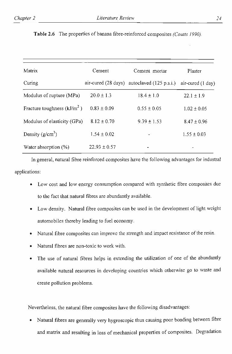
(when the composite contains 8%) fibres by mass). In research conducted at CSIRO (Coutts
1990), Australia, 8% by weight of banana fibre was fabricated with autoclave cement mortar, air-
cured cement and air-cured plaster. The composite products had adequate mechanical and
physical properties for building applications. Selected properties of banana fibre reinforced
materials are shown in Table 2.6.
Chapter 2 Literature Review 24
Table 2.6 The properties of banana fibre-reinforced composites (Coutts 1990).
Matrix Cement Cement mortar Plaster
Curing air-cured (28 days) autoclaved (125 p.s.i.) air-cured (1 day)
Modulus of mpture (MPa) 20.0 ± 1.3 18.4 ± 1.0 22.1 ± 1.9
Fractiire toughness ( k j W ) 0.83 ±0.09 0.55 ±0.05 1.02 ±0.05
Modulus of elasticity (GPa) 8.12 ±0.70 9.39 ±1.53 8.47 ±0.96
Density (g/cm^) 1.54 ±0.02 - 1.55 ±0.03
Water absorption (%) 22.93 ± 0.57
In general, natural fibre reinforced composites have the following advantages for industral
applications:
• Low cost and low energy consumption compared with synthetic fibre composites due
to the fact that natural fibres are abundantly available.
• Low density. Natural fibre composites can be used in the development of light weight
automobiles thereby leading to fuel economy.
• Natural fibre composites can improve the strength and impact resistance ofthe resin.
• Natural fibres are non-toxic to work with.
• The use of natural fibres helps in extending the utilization of one of the abundantly
available natural resources in developing countries which otherwise go to waste and
create pollution problems.
Nevertheless, the natural fibre composites have the following disadvantages:
• Natural fibres are generally very hygroscopic thus causing poor bonding between fibre
and matiix and resulting in loss of mechanical properties of composites. Degradation

Chapter 2 Literature Review 25
of composite materials based on natural fibre is one of the major limitations for
durability.
• Currently, since natural fibres are not available in the required length and form, the
process should be firstly to obtain the requhed natural fibre form.
• Suitable inexpensive resins should be developed for better performance and better
compatibility with natural fibres.
2.2.2 HYBRID FIBRE COMPOSITES
Hybrid fibre composites contain two or more kinds of fibres, which are incorporated into a
single matrix. Although individual types of fibres may contribute some desirable property, the
particular interest in composite material systems lies in optimizing the different contributions
from different types of fibres, whilst at the same time, paying attention to optimizing cost
effectiveness. Hybrid fibre composites therefore provide researchers an opportunity for tailoring
composites to achieve desired properties (Kretsis 1987).
According to the arrangements of fibres and layers, hybrid fibre composites can be
generally classified into the following types (Chou 1992):
• Intermingled: Different fibre materials are mixed together and passed through a
matrix simultaneously,
• Interlaminated: Each separate laminate containing just one type of fibre. The
laminae are bonded together in a matrix,
• Interwoven: Composed of fabric reinforcements where each fabric contains more
than one type of fibre.

Chapter 2 Literature Review 26
The Figure 2.6 shows the three types of hybrid fibre composites.
O O Q * O.O # 0 0 O.O O Q O fi*^ i?0« CO • O j f O o
fo °%°oo»%o%«o * rP ^ O O Om Of o o o°o QQ* o°o o*o•^O •
Intermineled
Q O Q gOn nOr^ nOp »0 • « ^
0"Q • • • • • • • • • • • • • • •
Oo° °oO Oo<^ OQ"^ O O O O ^ Oo"oo"on"Co"on
Interlaminated
Interwoven
Figure 2.6 The schematic for types of hybrid fibre composites ("C/iow 1992).
One of the advantages of hybrid fibre composites is flexibility in the choice and
disposhion of reinforcements (Hancox 1981). Fibre hybridization can be a very useftil way of
balancing mechanical properties (such as requirements for strength and stiffness) in various
directions at minimum cost. In general, the hybrid effects are likely to be dominated by the
properties of each individual fibre and theh law of mixture (such as fibre volume fraction).
Hybrid composites made whh a high performance fibre and another lower performance fibre or a
high cost fibre and a cheaper fibre, may have adequate properties for a specific application. It
may be possible to save weight and reduce cost while getting improved mechanical and thermal
properties, compared with an individual fibre reinforced system.
Chapter 2 Literature Review 27
Applications of hybrid fibre composites have grown rapidly in the last decade or so
(Hancox 1981). At present, the most popular fibre hybridizations are glass-carbon and kevlar-
carbon fibres. The growth of hybrid fibre composites has been encouraged by the demand for
high-performance engineering material and economy issues, especially where light weight is of
great importance. Turning to specific applications, hybrid fibre composites have been used in
aerospace industry, such as helicopter rotor and drive shafts. Also, hybrid fibre composites are
attractive for commercial transportation and building industries.
Overall, effective hybrid fibre combinations have simply taken the composite material
approach one step further than individual fibre laminates. Fibre hybridization improves the
possibilities for total optimization of costs and properties. However, the negative aspects of fibre
hybridization are an increase in the complication of material responses and analytical complexity.
The reason is that, in the case of layered hybrids, it is hard to distinguish between the two or more
fibres, especially for hybrids of high-performance. Thus, processing errors may easily be made.
2.2.3 SHORT FIBRE COMPOSITES
For various applications, many fibre composite materials are not reinforced by continuous
fibres but by short fibres. Composites reinforced with discontinuous fibres are referred as short
fibre composites. Short fibres have no constant definition of fibre length. Depending upon the
dispersion of fibres in the matrix, the fibre aspect ratio (length/diameter) is usually a measurement
of fibres relative length (Chou 1992). Although short fibres have been used to reinforce metals
and ceramics, the majority of short fibre composites are based upon polymeric matrices.

Chapter 2 Literature Review 28
In some applications the stress distribution can be exactly determined. In these situations
unidirectional fibre composites have strong advantages, because they have high strength and
modulus in the direction of the fibre axis, but are general very weak in the transverse dhection.
However, if the stress state is not readily predictable, or the expected service stiesses are
approximately equal in all directions, the unidirectional fibre composites lose this advantage.
With short fibre composites, it is possible to obtain nearly equal mechanical properties in all
directions, by virtue ofthe random nature of fibre orientation within the composite material. An
effective way of producing an isotropic laminate is to use randomly oriented short fibres as the
reinforcement. The moulding compounds consisting of short fibres that can be easily moulded by
injection or compression, and they are also economical and can produce generally isotropic
composites. In general, short fibre composites are less expensive for mass production techniques
than continuous fibre composites (Folks 1982).
2.3 COMPOSITES MANUFACTURE
There are many differences between composites and metallic materials on the choice of
manufacturing method. With composite materials, processing techruque has a direct influence on
fibre volume fractions, fibre disfributions, fibre orientations and details of laminate lay up. Many
of the main issues, which affect component performance, are linked with manufacturing method.
Composite products ofthe same form, but of different fabrication methods, could have markedly
different properties. This not only affects mechanical properties such as strength and modulus,
but also other properties such as the interface between fibre and matrix, thermal and electrical,
chemical resistivity and intemal damping. A cost-effective and reliable manufacturing method is

Chapter 2 Literature Review 29
also a key issue in the successful production application of composite materials. The effect of
manufacturing process on cost components between equipment, toolmg, labor and materials varies
greatly. The balance between achieving the maximum level of performance and minimising
processing costs should satisfy the requirements of a particular application. For example, in the
automotive industry, there is more emphasis on the development of manufacturing methods that
can support mass production rates. Unit costs and production rates commensurate with large
volumes are needed.
Currently, there are many manufacturing processes for composite materials. Brief
characteristics of major manufacturing processes are described as follows (Eckold 1994):
• Continuous reinforcement processing
- Filament winding: A band of continuous fibres impregnated with resin is
wrapped around a rotating mandrel and cured to produce axially symmetric hollow
parts. The applications are strong, stiff shell stmctures such as automotive drive
shafts and pipe lines.
- Pultrusion: Pultmsion is effective for producing long, straight stmctural
components of constant cross-sectional area. The common pultmded products are
solid rods, hollow tubes, flat sheets and various types of beams.
• Hand lay up processes
In these processes, components are normally produced on a mould, coated with a
suitable release agent. Hand lay up processes have the advantage of low cost and
versatility. The details will be described in the following section 2.3.1.
• Molding processes
- Matched - die molding: Matching steel male and female dies are to be used to

Chapter 2 Literature Review 30
form a cavity ofthe shape ofthe component. Advantages of matched -die
molding are high dimensional control and good surface finish.
Vacuum bagging: The procedure involves the use of a flexible plastic
membrane that is molded over the surface of the lay up to form a vacuum-tight
bag. It is used in aerospace industry.
- Autoclave molding: It is similar to the vacuum bag process except that greater
pressures are used in the lay up.
• Resin injection process
- Resin - transfer molding (RTM): Several layers of dry continuous strand mat or
woven roving are placed in the bottom half of a two-part mould, and a catalyzed
liquid resin is injected into the mould via a centrally located spme when the mould
is closed. The RTM process has a low tooling cost compared with molding
process. It has been successfully used in molding such parts as cabinet wall, water
tanks and boat hulls.
- Reaction injection molding (RIM): RIM uses relatively low pressures to
produce large moldings principally in polyurethane elastomer. The major
difference from RTM is that the RIM brings two fast-reacting components together
and mixes them just prior to injection into the mould.
2.3.1 H A N D LAY-UP PROCESS
Hand lay-up is perhaps the oldest method of fabrication of sti^ctural composites, but it
still seems to offer a low cost, simple, efficient manufacturing method with no size limitations,
and produces a high gloss finish on one surface. Its principal limitations are that there is only one

Chapter 2 Literature Review 31
finished surface, and the quality of the product is very much subject to operator skill. Another
advantage of hand lay-up is low capital cost. It is particularly suited for one-offs or short
production mns and can be used for large components such as hulls of boats and swinuning pools.
In hand lay-up, a male or female mould is used. After the mould is prepared with a release
agent to prevent sticking, gel coat is used to give a decorative and protective surface. Reinforcing
material is placed on or in the mould. The liquid thermosetting resin is mixed with a curing agent
and applied with a bmsh or roller taking care to work it into reinforcement. The most commonly
employed resins are polyesters or epoxies, and curing is usually at room temperature. The prime
consideration is the viscosity and the working time of resin (Scwartz 1984).
The major disadvantages of hand lay up are the low reinforced volume fractions and the
difficulty in removing all of the trapped air, thus, the mechanical properties are decreased. Also,
being a labor-intensive technique, provision must be made in the design for the greater degree of
variability.
2.4 COMPOSITE MATERIAL TESTING
Material properties are usually determined by conductmg mechanical and physical tests
under controlled laboratory conditions. Due to die special characteristics of composite materials,
such as ortiiofropic nattu-e, interfacial effects between fibre and matrix and the variety of possible
failure modes, the mechanical testing methods that are used for conventional materials are
different from tiiose used for composite materials (Nielsen 1994). The development of tiiese

Chapter 2 Literature Review 32
unique test methods has been a major challenge for the experimental mechanics field. The
experimental techniques, which are used for this project, are discussed in the next section.
2.4.1 DYNAMIC MECHANICAL ANALYSIS (DMA)
Polymers are often viscoelastic in nature. Viscoelasticity implies that a material will
exhibit mechanical behavior with characteristics representative of both a viscous liquid and purely
elastic solid. A viscous liquid in a non-hydrostatic stress condition has a capacity for dissipating
energy, but none for storing it. Perfectly elastic materials have the capacity to store mechanical
energy with no dissipation of energy. When composite stmctures are subjected to dynamic loads,
many exhibit an elastic solid and a viscous fluid behavior. The deformation and the
corresponding strain may be decomposed into elastic and viscous components. It is this dual
nature of composite materials which makes their behavior so complex and interesting. The
balance between elasticity and viscosity varies with temperature, fibre type, fibre amount, fibre
volume fraction and degree of cross-linking(FerA7 1980).
The investigation of the dynamic mechanical behavior over a wide temperature, frequency,
and dynamic stress range is useful in studying the stmcture of polymers and variations in
properties. These parameters have been used to determine the glass transition region, relaxation
spectra, degree of crystallinity, molecular orientation, crosslinking and to measure the damping
properties. For any application of polymers, the stiffness variation and thermal expansion must be
taken into account whenever a component is subjected to a wide range of temperature in service
(Haddadl995).

Chapter 2 Literature Review 33
A DMA (Dynamic Mechanical Analysis) instrument operates on the principle of applying
stress in a periodic, cyclic fashion (typically with sinusoidal character) at controlled frequency.
Dynamic mechanical properties are usually described in terms of a complex modulus E ' , which is
divided into storage modulus E (expressing a material's ability to store energy), and the loss
modulus E' (expressing a material's ability to dissipate energy). The DMA measures a strain that
is in phase with the applied stress in elastic portion, while viscous portion will exhibit a strain that
is 90°C out of phase. DMA resolves the complex modulus into an elastic modulus and viscous
modulus (Campbell and White 1989):
E'=E'+iE" and \E'\ = (E'^ +E"'y (2.1)
The ratio of loss modulus and storage modulus is called tan5 (the 'loss tangent'):
tanS = ~ (2.2) E
Tan 5 gives the relative ability ofthe material's ability to store and dissipate energy. High Tan 5
indicates more viscous behavior and low Tan 8 indicates more elastic behavior.
Tg is glass transition temperature. Tg values depend on the chemical stmcture, processing
conditions, molecular weight and compositional changes. Amorphous polymers are relatively
hard and rigid below Tg, in the so-called glassy region. Above Tg, however, the amorphous
polymers are soft and flexible. Tg is important to understand die properties of polymers. It can be
considered as one of the important material characteristics. Polymer mechanical and physical
properties change rapidly with temperature in the glass transhion region. The storage modulus
decreases rapidly, and the loss modulus and tangent deha increase to peak.

Chapter 2 Literature Review 34
Tg measurements may be made by many different methods, such as Differential Thermal
Analysis (DTA), Differential Scanning Calorimetry (DSC) and Dynamic Mechanical Analysis
(DMA). Different values of Tg are often obtained from different measuring techniques.
Moreover, even within a given technique, for example, DMA, there are many variations on
detecting and calculating Tg. For example, the Tg region can be taken as storage modulus onset,
loss modulus peak or onset, or Tan8 peak (Cassel and Twombly 1991).
One ofthe simplest results available from a DMA instrument is a curve of storage modulus
versus temperature. Temperature regions are encountered where the storage properties decline
rapidly. The loss modulus rises to a local maximum as the storage modulus declines. Another
important graphical result, is that Tan 6, follows the loss modulus (Sepe 1997), although the two
properties do not exhibit transitions at exactly the same stages of a test. DMA instruments may
employ many different geometries and apply the stress in various modes under temperature/time,
stress, frequency, creep-recovery and the constant force scan modes.
2.4.2 STATIC FLEXURE TESTING
Static flexure testing is performed to determine the rigidity of the hybrid fibre composites,
and h is done under bending loads. Three point bending flexural tests are usually used in the
composite material tests, because the sample preparation and fixtures are very simple (Chang
1995).
According to ASTM D790, the flexural stiength in a three-point flexural testing is given by:
Flexural modulus is calculated by:

Chapter 2 Literature Review 35
E = mlJ_ 4bt'
where: a: flexural strength
t: sample thickness
(MPa)
E: flexural modulus (GPa)
P: maximum load at failure (N)
b: sample width (mm)
(mm)
(2.4)
L : sample length between the two support points. (mm)
m: initial slope ofthe load deflection curve. (mm)
The three point bending is shown in Figure 2.7.
'1 23 ̂
* U.5L *
U 1
t
A
* 0.5L ^
.. •
^ 1 "fz^Tm
Figure 2.7 Schematic illustration of 3-point bendmg test.

Chapter 3
Material Fabrication and Experimental Methods
3.1 MATERIALS
3.1.1 BANANA FIBRE
The banana fibre used in the study is 10 mm long chopped banana fibre. The banana stalk
was supplied from a banana plantation in Woolgoolga, N.S.W, Australia.
Banana fibres were obtained from the pseudo stem of the banana plant. The pseudo stem,
which is surrounded and supported by leaf sheathes, is called the stalk. The leaves were separated
from the pseudo stem and cut into 1 m length and 0.02 m width. The extraction ofthe fibre from
the stripped leaf sheath (cleaned well) was done by hand scraping using a soft wooden plank. The
pith was then removed continuously until the fibres appeared clean. These strands were dried and
then used for fibre preparation by cutting the sfrands into -10 mm in length.

Chapter 3 Material Fabrication and Experimental Methods 37
The equilibrium water content (EWC) of banana fibres is defined as the percentage
amount of water absorbed under ambient conditions and can be calculated from the difference in
mass before and after exposure to ~110°C for about an hour (this will drive any water away). The
EWC of banana fibers used in this investigation was determined to be 12%.
Figure 3.1 10 mm long banana fibres
3.1.2 GLASS FIBRE
The glass fibre used in this study is circular cross-section E-glass chopped stt-and mats
from Resin and Fibreglass Services Pty. Ltd., Australia. Longer chopped fibreglass strands (up to
50 /Mm in length) are mixed with a resinous binder (a polyester powder) and spread in a random
two-dimensional fashion to fonn chopped sfrand mats. These mats are typically used for hand
lay-up molding and provide equal properties in all of tiie in-plane directions ofthe stmcture.
3.1.3 MATRIX
The resin used in tiiis work was unsatiu-ated polyester resm (resin number: 837E) from
Resin and Fibreglass Services Pty. Ltd., Austi-alia. It is one of tiie conunercial thermoset

Chapter 3 Material Fabrication and Experimental Methods 38
polymers which contain a number of carbon, C=C double bonds. Unsaturated means that the resin
is capable of being cured from a liquid to a solid state. A typical unsaturated polyester may be
prepared by reacting an unsaturated dibasic acid, maleic anhydride, with a glycol, ethylene glycol.
The resulting molecule chain has the following general formula.
H H
HO-C-C = C-C4-OH + H
O H H O
Maleic Anhydride
0-C-C-OH
H H
Ethylene Glycol
-• HO
H H _
* *
C - C = C - C - 0 - 0 - C - C - 0 4 H + H 2 0
O H H O H H n = 3 - 5
Unsaturated Polyester Molecule
Figure 3.2 Unsaturated polyester molecule (Mallick 1988).
The asterisk (*) denotes the saturation points (reactive sites)
in the unsaturated polyester molecule.
The curing reaction for polyester resin will start immediately upon addition of a suitable
catalyst and accelerator. The polyester resin used in this work is normally pre-accelerated. The
accelerator proportions are already adjusted to give the most suitable gelling and hardening
characteristics. Once die catalyst is added, tiie curing reaction starts immediately at room
temperature. The proportions of catalysts are recommended ranging between \% and 4 % of die
resin weight, depending on die type of the catalyst. In this work, die catalyst is Methyl - Ethyl -

Chapter 3 Material Fabrication and Experimental Methods 39
Ketone - Peroxide (MEKP), produced as a liquid (40%) in Dimethyl phthalate solution). The
proportion of catalyst was chosen on a 2% scale (20 ml per litre polyester resm).
The setting reaction of polyester resin occurs in four stages:
• Pot life time: during which the resin still remains in a workable liquid form
although it continues to thicken.
• Gel time: the time taken for the resin to set to a soft gel.
• Hardening time: further time taken for the resin to become hard enough for the part
to be removed from its mould.
• Maturing time: further period of time over which the molding will continue to gain
hardness and eventually, complete stability. When fully matured the molding will
have its maximum strength, hardness, chemical resistance and stability.
These four stages are illustrated in Figure 3.3
GEL TIME
Figure 3.3 Four stages of setting action ofthe resin (Warring 1993).
The curing time for polyester resin depends on the proportions of catalyst. An increase in
catalyst content will result in a more rapid increase in hardening. Also the working time of resin
should be mentioned here. The working time means tiie speed of reaction between resin and
catalyst, which is dependent on both temperature and catalyst quantity. The polyester resin

Chapter 3 Material Fabrication and Experimental Methods 40_
normally has a pot - life in the 20 to 30 minutes range at room temperature and should not
normally be used below 15 C or above 35 C.
3.2 COMPOSITION OF HYBRID FIBRE COMPOSITES
3.2.1 RULE OF MIXTURES
The mle of mixtures has been used to calculate the relative volume or weight contents of
the various constituent materials. In hybrid fibre composites, the three constituents in die
fabricated lamina are glass fibres, banana fibres and polyester resin. Fibre volume fraction is
usually used in theoretical calculations for properties such as strength, modulus etc. However, tiie
mle of mixtures is not suitable to measure the volume fractions of these three constituents, since it
assumes volume additivity and does not take account of synergistic volume interactions. In order
to calculate the volume fractions, they are converted into the weight fractions. The fibre weight
fractions can be determined directiy from the given proportions (Sheldon 1986).
The following formulae were applied to calculate the glass fibres, banana fibres and
polyester resin volume fractions:
^ K^PJ (3.1)
n = {^JPb) (3.2) [^gl Pg)+{^bl Pb)+{^ml Pn)
v.=;-v,-v. 0-^>

Chapter 3 Material Fabrication and Experimental Methods 41
^n,=^-^g-^h (3.4)
where: w : the weight fraction of glass
w, : the weight fraction of banana fibres
w : the weight fraction of matrix m ^^
V : the volume fraction of glass fibres
v^ • the volume fraction of banana fibres V : the volume fraction of matrix
m
p : thedensity of glass fibre (kg/m )
p. : the density of banana fibre (kg/m^)
p : the density of polyester resin (kgW)
The density of composite lamina p also can be calculated according to equation (3.5).
_ ^ /J j j
{w^/p^)+{wjpi,)+{w„,/p„,)
The composite weight W is the muhiplication ofthe composite volume K, and /?..
W^=V^xp^ (3.6)
The glass fibre weight W :
W^=W^xw^ (3.7)
The banana fibre weight W,:
W =Wxw, (3.8)

Chapter 3 Material Fabrication and Experimental Methods 42
32.2 CONSTITUENTS OF HYBRID FIBRE COMPOSITE LAMINAE
The composite laminae were made with different fibre weight fractions which are defined
in three groups including 10 wt%), 25 wt%), 40 wt% hybrid fibre weight fractions. Each group was
subsequently divided into five samples of different glass fibre and banana fibre fractions as shown
in Tables 3.1, 3.2 and 3.3.
The Figure 3.4 shows the cross-sectional view of fibre composites, which were used in this
project. The all glass fibre reinforced composites (GP1005, GP2505 and GP4005) are referred as
B type, the all banana fibre reinforced composites (BP1004,BP2504 and BP4004) are referred as
A type, the hybrid glass-banana fibre composites are referred to as C type.
K^J^^SJ8^$SJSJ^^^J^;8i$8^^
«S88«8«8gg$gS88ggggg
tiSiSiSi;iSi;iSi;6iSiimi^^
(A) All Banana (B) All Glass (C) Hybrid
Figure 3.4 Cross - sectional schematic view of lay-up sequences of
glass and banana fibre in a polyester matrix.

Chapter 3 Material Fabrication and Experimental Methods 43
Table 3.1 The composition of \OyA% hybrid fibre composites. Data presented is average of 3 samples.
Sample I D Wf Wg W^ W, V, Wg w^ Vg v^ p , ±0.5 ±0.5 ±0.5 ±0.5 ±2.5 ±1.0 ±1.0 ±2.0 ±2.0 ±0.05 (g) (g) (g) (g) (cm') (%) (%) (%) (%) (g/cm')
GP1005 7.56 7.56 0 73.75 64.85 10.31 0 5.11 0 1.13 (All glass)
GBPlOOl 7.58 5.61 1.97 75.85 66.99 7.39 2.59 3.62 2.39 1.13
GBP1002 7.92 3.96 3.96 71.25 65.52 5.56 5.56 2.71 5.08 1.09
GBP1003 7.27 1.82 5.45 70.45 66.36 2.58 7.74 1.24 6.98 1.06
BP 1004 7.25 0 7.25 67.85 65.10 0 10.68 0 9.54 1.04 (All banana)
Where: Wg •, The weight of glass fibres. Wb: The weight of banana fibres Wc : The weight of composites Vc : The volume of composites Wg : The weight fraction of glass fibres w^ : The weight fraction of banana fibres Vg : The volume fraction of glass fibres v^; The volume fraction of banana fibres Pc : The density of composite lamina W/: The weight of total fibres
Table 3.2 The composition of 25wt%) hybrid fibre composites. Data presented is average of 3 samples.
Sample ID Wf Wg Wb Wc Vc Wg Wb Vg vj Pc ±0.5 ±0.5 ±0.5 ±0.5 ±2.5 ±1.0 ±1.0 ±2.0 ±2.0 ±0.05 (g) (g) (g) (g) (cm') (%) (%) (%) (%) (g/cm')
GP2505 20.55 20.55 0 80.15 64.68 31.77 0 13.91 0 1.24 (All glass) GBP2501 17.30 12.25 5.05 71.25 64.89 17.19 7.09 8.94 6.94 1.10
GBP2502 18.30 9.45 8.85 61.85 56.70 15.28 14.30 7.94 13.99 1.09
GBP2503 19.20 5.15 14.05 64.55 61.01 7.98 21.77 4.02 20.59 1.06
BP2504 18.45 0 18.45 66.45 65.14 0 27.77 0 25.31 1.02 (All banana )

Chapter 3 Material Fabrication and Experimental Methods 44
Table 3.3 The composition of 40wt%) hybrid fibre composites. Data presented is average of 3 samples.
Sample ID Wf ±0.5 (g)
Wg ±0.5 (g)
Wb ±0.5 (g)
Wc ±0.5 (g)
Vc ±2.5 (cm')
^g
±1.0 (%)
^b
±1.0 (%)
Vg
±2.0 (%)
Vb
±2.0 (%)
Pc ±0.05 (g/cm')
GP4005 36.24 36.24 0 81.15 61.29 44.66 0 27.44 0 1.32 (All glass) GBP4001 34.32 25.74 8.58 72.45 60.88 35.53 11.84 20.87 13.11 1.19
GBP4002 33.68 17.12 16.56 70.95 62.42 24.13 23.34 13.39 24.38 1.14
GBP4003 31.44 7.86 23.58 67.75 60.29 11.62 34.85 6.06 34.26 1.12
BP4004 30.15 0 30.15 64.25 63.72 0 46.93 0 43.79 1.01 (All banana)
3.3 FABRICATION OF BANANA/GLASS POLYESTER COMPOSITE LAMINAE
3.3.1 FABRICATION FACILITY
A hydraulic press was used for fabrication of banana fibre/glass-polyester hybrid
composite lamina. This machine was designed to manufactiu-e composite material boards with a
maximum dimension of 450 mm x 300 mm, and a thickness up to 50 mm. It provided control of
temperatiu-e, and featured an auxiliary air boost compressor and a pedal to facilitate pressure
contiol. The hydraulic platen press had the capacity in excess of 200 bar applied pressure.
The composite lamina was formed in a mould. This mould was composed of aluminum of
rectangular bars and two flat plates, as shown in Fig. 3.5. The press set up is also shown
schematically in Fig. 3.5.

Chapter 3 Material Fabrication and Experimental Methods 45
Aluminium rectansular bars
Top aluminium plates
II
Hydraulic cylinder
Bottom aluminium plates. Base mould
Figure 3.5 Schematic of composite materials pressed mould.
3.3.2 FABRICATION PROCEDURES
The mould for fabrication of composite lamina was completely cleaned (removing any
remaining parting agent if the mould has been used before). It was free from surface damage,
along with grease or dust, in order to obtain good surface finish of composite lamina. Then the
mould was treated with release agent to promote sample removal after curing. The release agent
was applied sparingly either by spray or bmsh, otherwise it took too long to dry. The release
agent must be left to dry thoroughly; otherwise, it would not form a proper skin, and the moulding
would stick.
Ideal air temperature had to be at least 15 C. If the temperature was lower than this, more
than 2%) catalyst had to be used to compensate for the decrease in thermal activation. If the
temperature was below about 10 C, however, h was best to leave laying-up until conditions
improved. It was also important that the air should be dry or reasonably dry. Laying-up must not

Chapter 3 Material Fabrication and Experimental Methods 46
be attempted in damp or excessively humid conditions, due to inhibition of the curing reaction by
the moisture in the air.
Chopped glass fibre strand mats were cut to 150 mm x 100 mm. After weighing tiie glass
fibres, glass strand mat, banana fibres and polyester resin, the first layer of glass strand mat, was
put on the bottom of the mould. The polyester resin was prepared by adding approximately 2%
catalyst of total polyester resin by weight.
The matrix then was poured over the first glass mat layer and distributed with a wide, soft
bmsh, in order to obtain an even distribution of resin with a continuous application. In the
meantime, the mixture consisting of banana fibres and resin was mixed carefully in a beaker with
a stirrer bar. Mixing ofthe glass and banana fibres took approximately 10 minutes. The mixture
was then evenly distributed on the first glass layer by rolling or bmshing. The second glass mat
layer was put on the top and the matrix was bmshed on surface of layer again. Successive layers
were added in a similar fashion.
Uniform distribution ofthe fibres and resin is important but also difficult to achieve. Care
was taken at all times to minimize the potential for formation of defects. Bmshing with a dabbing
motion was used to avoid sweeping or 'painting' strokes. Dabbing down was followed by rolling
to ensure proper consolidation.
The plate, which contained hybrid fibres/resin mixture was placed on the press. A second
flat plate was put on top of the mixture. The fibres/resin mixture was then pressed by the top
mould until the desired thickness of 4 mm. Pressure up to 200 bars was applied to the top mould.
The fibres/resin mixture was compressed at a constant pressure of 200 bars, at room temperature
and for 24 hours of curing.

Chapter 3 Material Fabrication and Experimental Methods
3.4 SPECIMEN TESTING
3.4.1 WATER ABSORPTION
The water absorption values were obtained in accordance with ASTM C220. The samples
were dried in an oven at 100 ± 5 °C for a period of 24 hours. After cooling down in a dessicator to
room temperature, the dry weight of each was determined and recorded.
Samples were then immersed in distilled water at room temperature for a period of 24
hours. Surface water was quickly removed from each sample using a towel prior to the
measurement and the wet weight in air was recorded. All masses were recorded to the nearest
O.Olg.
The water uptake was then determined relative to the dry weight of the sample using
following equation:
W -W W =-^ ^xlOO%
W..
(3.9)
where: W„,: Water absorption value, W^ : Wet weight, W^: dry weight.
The water absorption results are summarised in Table 3.4
Table 3.4 Water absorption of hybrid composites (24 hours at room temp.)
Sample
GBPlOOl GBP 1002 GBP 1003 BP1004 GP1005
Water absorption (%)
1.72 3.46 3.76 6.86 1.28
Sample
GBP250I JBP2502 3BP2503 BP2504 GP2505
Water absorption (%)
1.69 3.17 7.86 15.74 1.45
Sample
GBP4001 GBP4002 3BP4003 BP4004 GP4005
Water absorption (%)
4.17 4.82 9.82 20.13 2.94

Chapter 3 Material Fabrication and Experimental Methods 48
3.4.2 DMA TESTING
The temperature/time scan mode was used in this work for both wet and dry specimens.
3.4.2.1 Facility
The dynamic mechanical analysis system used was a Pekin-Elmer 7-series thermal analysis
system, consisting of a TAC 7/DX thermal analysis instmments controller and a DMA7 dynamic
mechanical analyzer. With this analyzer the specimen could be analyzed by DMA parameters
versus temperature and stress without changing the fiirnace and sample mounting system. This
system contains a software which is needed to control the system, perform experiments and
analyze experimental data.
3.4.2.2 Sample preparation
Each sample was cut by high speed handsaw for temperature/time and stress mode. Three-
point bending dimensions of each sample are shown in Figure 3.6:
Height (y)
\
Displacement (Ay)
x=I4.5 mm
r- Width (X)
v=2 0 mm 7r=3.5 mm
Figure 3.6 Three-point bending dimensions (DMA manual 1995).

Chapter 3 Material Fabrication and Experimental Methods 49
3.4.2.3 Temperature scan mode
In the temperature/time scan mode, the temperature is programmed and the oscillation
frequency and stress are held constant. Temperature-dependant behavior is characterized by
monitoring changes in strain and phase. Modulus and viscosity, as well as other standard
reporting variables may be readily quantified for these materials as a function of temperature/time.
Flexural storage modulus and the loss tangent were determined during heating over the
o o o
temperature range 25 C -180 C at a rate of 5 C/min.
3.4.3 STATIC FLEXURE TESTING
Static flexural strength and modulus were measured by a three point bonding method. The
samples for testing were cut by band saw with a dimension of-70 mm x 30 mm x 4 mm.
The testing was performed on Instron Model 8500 Plus Testing System. The system
applies load, using a hydraulic actuator, to a specimen of the material under test. The test speed
used in this work was 0.25 mm/second.

Chapter 3 Material Fabrication and Experimental Methods 50
Figure 3.7: The Instron Model 8500 Plus Testing System.

Chapter 4
Results and Discussion
4.1 DYNAMIC MECHANICAL ANALYSIS
4.1.1 FLEXURAL STORAGE MODULUS VERSUS TEMPERATURE
Figures 4.1, 4.2 and 4.3 show the variation in dynamic flexural storage modulus with
temperature for 10%), 25% and 40%) banana-glass hybrid fibre composites, respectively, under dry
conditions. These plots are distinguished by three distinct zones, which are called glassy,
transition, and mbbery. The glassy zone is characterized by a region where no significant change
in the storage modulus is evident until the onset temperature of glass transition is reached. The
onset temperature of glass transhion indicates the temperature at which the material's stiffness
begins to decrease such that the material is no longer able to bear a load without undergoing a
large deformation. In the second region, known as the tiansition region, the flexural storage
modulus drops quite significantly and the material loses its rigidity. This zone is located in the
temperature range of approximately 3 5 ^ - lOOt. With ftjrther increase in temperattue, the
storage modulus continues to decrease quickly until it reaches the beginiung of the third region

Chapter 4 Results and Discussion 52
also known as the mbbery region, which extends beyond 100 C. AU tests were stopped at 150 C
when the materials were well into the mbbery region.
3.0
CD
I o
2
I
2.5 -
2.0
1.5
1.0 -
0.5
0.0
BP1004
GP1005
GBP1001
GBP1002
GBP1003
25 50 75 100
Temperature (C)
125 150
Figure 4.1: The variation in flexural storage modulus with temperature for 10% hybrid composites (dry condition).

Chapter 4 Results and Discussion 53
o
D) 2
2
GP2505
GBP2501
GBP2502
GBP2503
BP2504
125 Temperature (°C)
Figure 4.2: The variation in flexural storage modulus with temperature for 25% hybrid composites (dry condition).
4.0
0.0
GP4005
GBP4001
GBP4003
GBP4002
BP4004
25 ~\— 50
— I — 75 100 125
Temperature (°C)
150
150
Figure 4.3: The variation in flexural storage modulus with temperature for 40%) hybrid composites (dry condition).

Chapter 4 Results and Discussion 54
Figures 4.4, 4.5 and 4.6 show the variation in flexural storage modulus with temperature
for 10%), 25%) and 40% hybrid fibre composites, respectively, under wet conditions. As in the
case of the dry condition, curves can be demarcated into three distinct zones, which are glassy,
transition, and mbbery. The variation in flexural storage modulus of the hybrid composites under
wet conditions follows the same trend as that observed in the dry condition, but at a reduced
magnitude due to water absorption causing loss of mechanical properties. There is no discemable
variation in the transition temperature for equivalent samples from the wet condition to the dry
condition.
CD
I o
2
2
I
2.5
2 .0-
1 .5 -
1.0-
0.5-
0.0 25
GP1005
GBP1001
GBP1002
GBP1003
BP1004
50 75 100 125 150
Temperature ( C)
Figure 4.4: The variation in flexural storage modulus wdth temperatiire for 10%) hybrid composites (wet condition).

Chapter 4 Results and Discussion 55
2 I
3.0
2.5-CD
5 2.0-
o E o
2 S <0
1.5-
1.0-
0.5-
o.a 25 100
Temperature (°C) 125 150
CD
o
E
2
I
Figure 4.5: The variation in flexural storage modulus with temperature for 25% hybrid composites (wet condition).
.Si 0.5 -
0.0
GP4005
GBP4001
GBP4002
GBP4003
Temperature (C)
150
Figure 4.6: The variation in flexural storage modulus with temperature for 40% hybrid composites (wet condition).

Chapter 4 Results and Discussion 56
Tables 4.1, 4.2 and 4.3 show the value (average of three specimens from each of hybrid
samples) of initial flexural modulus of 10%, 25% and 40% hybrid fibre composites along witii
their onset temperature of transition under dry and wet condition.
Table 4.1: Characteristics of 10%) hybrid fibre composites.
Sample ID
GBPlOOl
GBP1002
GBP1003
BP1004 (aU banana)
GP1005 (all glass)
Initial flexural storage modulus (GPa)
Dry
2.41
2.08
1.98
1.86
2.73
Wet
1.79
1.62
1.31
1.12
2.19
Onset temperature (°C)
Dry
35
33
32
32
37
Wet
35
31
31
31
36

Chapter 4 Results and Discussion
Table 4.2: Characteristics of 25%) hybrid fibre composites.
Sample ID
GBP2501
GBP2502
GBP2503
BP2504 (all banana)
GP2505 (all glass)
Initial flexural storage modulus (GPa)
Dry
2.58
2.49
1.97
1.71
2.81
Wet
2.31
1.73
1.28
1.06
2.42
Onset temperature (°C)
Dry
38
37
35
33
40
Wet
34
36
33
33
38
Table 4.3: Characteristics of 40%) hybrid fibre composites.
Sample ID
GBP4001
GBP4002
GBP4003
BP4004 (all banana)
GP4005 (all glass)
Initial flexural storage modulus (GPa)
Dry
2.93
2.11
1.87
1.65
3.48
Wet
2.42
1.07
0.71
0.52
2.86
Onset temperature (C)
Dry
41
34
34
33
44
Wet
40
33
34
31
37
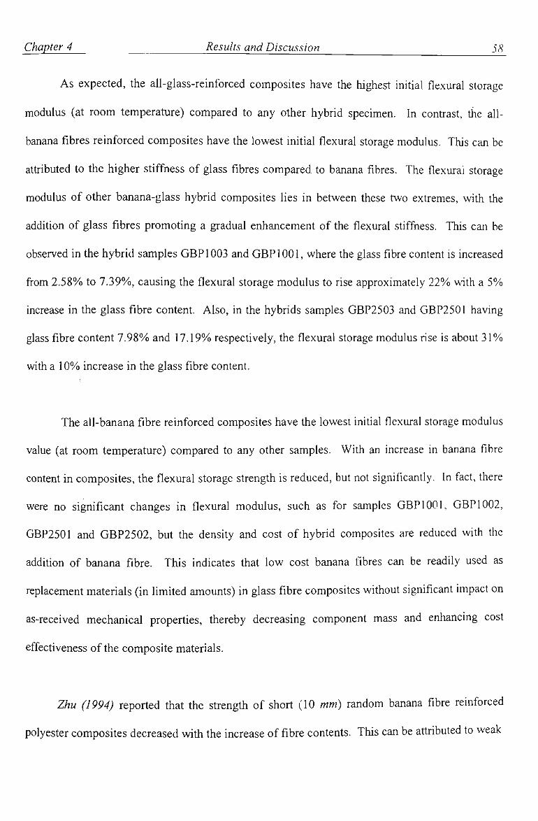
Chapter 4 Results and Discussion 58
As expected, the all-glass-reinforced composites have the highest initial flexural storage
modulus (at room temperature) compared to any other hybrid specimen. In contrast, the all-
banana fibres reinforced composhes have the lowest irutial flexural storage modulus. This can be
attributed to the higher stiffness of glass fibres compared to banana fibres. The flexural storage
modulus of other banana-glass hybrid composites lies in between these two extremes, with the
addition of glass fibres promoting a gradual enhancement of the flexural stiffness. This can be
observed in the hybrid samples GBP 1003 and GBPlOOl, where the glass fibre content is increased
from 2.58%) to 7.39%), causing the flexural storage modulus to rise approximately 22% with a 5%
increase in the glass fibre content. Also, in the hybrids samples GBP2503 and GBP2501 having
glass fibre content 7.98%) and 17.19%) respectively, the flexural storage modulus rise is about 31%)
with a 10% increase in the glass fibre content.
The all-banana fibre reinforced composites have the lowest initial flexural storage modulus
value (at room temperature) compared to any other samples. With an increase in banana fibre
content in composites, the flexural storage strength is reduced, but not significantly. In fact, there
were no significant changes in flexural modulus, such as for samples GBPlOOl, GBP 1002,
GBP2501 and GBP2502, but the density and cost of hybrid composites are reduced with tiie
addition of banana fibre. This indicates that low cost banana fibres can be readily used as
replacement materials (in limited amounts) in glass fibre composites without significant impact on
as-received mechanical properties, thereby decreasing component mass and enhancing cost
effectiveness ofthe composite materials.
Zhu (1994) reported that the strengtii of short (10 mm) random banana fibre reinforced
polyester composites decreased with the increase of fibre contents. This can be attributed to weak

Chapter 4 Results and Discussion 59_
interfacial bonding between fibre and matrix and probably indicates that the 10 mm fibres are less
than the critical fibre length required for optimum stiess transfer across the fibre/matrix mterface.
Indeed, with longer banana fibre strand (100 mm length), the flexural strength is enhanced with
the increase of banana fibre content.
With further rise in temperature the flexural storage modulus starts decreasing quickly,
begiiming at the onset temperature of transition. From Tables 4.1, 4.2 and 4.3, it can be observed
that the onset temperature ranged from about 3 0 1 - 45 "C depending on the composition of hybrid
fibre. The onset temperature ofthe all-banana fibre composites (BP1004, BP2504 and BP4004)
was around 3 3 ^ whereas it was at about 3 7 ^ for all-glass fibres composites. The onset
temperature of all the other hybrid composites was in between the two extremes. The hybrid
composites containing more banana fibres generally exhibit lower onset temperature of glass
transition.
Moisture generally decreases bonding strength between fibre and matrix and results in loss
of mechanical properties of composites (Wolff 1993). Satyanarayana (1981) however, reported
that the banana fibres from lower stalk (more water) were actually stronger than from higher
portions ofthe stalk, and frirthermore, that banana fibre strength increases with water absorption.
So, there are two competing mechanisms; fibre strength and interfacial bonding strength, both of
which affect the properties of hybrid fibre composites. From Tables 4.1, 4.2 and 4.3, h can be
noticed that the inhial flexural storage modulus of all samples decreases witii water absorption.
This can be attributed to the decrease in interfacial bonding stiength between fibre and matiix.
Therefore, tiie effect of interfacial bond strength between fibre and matrix dominates over tiie gain
in fibre properties.

Chapter 4 Results and Discussion 60
Tg for all samples was observed to decrease with water absorption. The rate of drop in
flexural modulus in the second zone, which signifies the slope of the curve in this zone, also
decreased with water absorption. The higher the drop rate, the steeper is the curve. From figures
4.4, 4.5 and 4.6, h can be seen that the slope ofthe curve in the wet condition is lower than in tiie
dry condition.
4.1.2 LOSS TANGENT VERSUS TEMPERATURE
Figures 4.7, 4.8 and 4.9 show the variation in the position of the loss tangent with
temperature for 10%, 25% and 40% banana-glass hybrid fibre composites under dry condition,
respectively. It is clear from the figures that in general, for all the samples tested, there is
practically no change in the loss tangent at the temperature below the onset temperature of glass
transition. This indicates glassy behaviour. At temperatures near the glass tiansition, the loss
tangent rises rapidly until it reaches a peak. The peak temperature is indicative of the glass
transition temperature (Tg) (Campbell and White 1989). After reaching the peak, tiie loss tangent
falls. At the end of this glass transhion region, around 125^, the loss tangent stabilizes indicating
rubbery behaviour.

Chapter 4 Results and Discussion 61
0.5
c (0
0 . 4 -
0 . 3 -
0 . 2 -
0.1 -
GBP1003
BP1004
0.0 25
-np-50
— I — 75 100
Temperature (°C)
GP1005
GBP1001
125 150
Figure 4.7: The variation in loss tangent with temperature for 10%) hybrid fibre composites (dry condhion).

Chapter 4 Results and Discussion 62
0.4-
c i2
0.3-
0.2-
0.1-
GBP2501
BP2504
0.0-25 50 75 100
Temperature (°C)
125
Figure 4.8: The variation in loss tangent with temperature for 25%) hybrid fibre composites (dry condition).
0.4^
150
GBP4003
GP4005
GBP4001
GBP4002
0.0-25 50 75 100
Temperature ( C)
125 150
Figure 4.9: The variation in loss tangent witii temperatiu-e for 40% hybrid fibre composhes (dry condition).

Chapter 4 Results and Discussion 63
The tan 8 data for each sample illustrated in Figures 4.7, 4.8 and 4.9 in the dry condition
reveal no systematic variation in glass transition temperatiu-e in each series. Composites
containing all glass fibres have a higher Tg than those contaming any amount of banana fibre. No
significant variations in Tg are observed as the banana fibre content is changed in each series.
Although Tg behaviour in composite materials is generally thought to be largely contioUed by tiie
matrix material, the data collected in the current work indicate that the type of fibres also plays a
role in determining the thermal behaviour ofthe composite materials.
Similar trends are apparent in Figures 4,10, 4.11 and 4.12, which represent tan 6 vs
temperature data for the samples tested under wet conditions. Variations from the dry condition
to the wet condition will be discussed at the end of this section.
0.5
.2
GP100&
GBP1003
BP1004
GBPlOOl
GBP1002
75 100
Temperature (C)
Figure 4.10: The variation in loss tangent with temperature for 10%) hybrid fibre composites (wet condition).
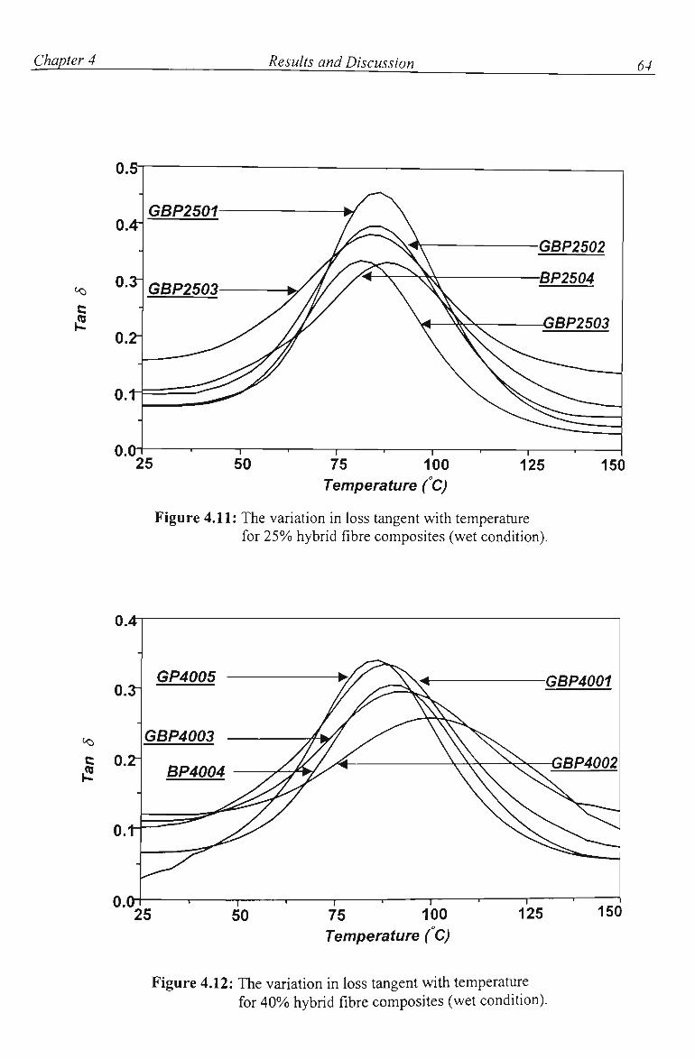
Chapter 4 Results and Discussion 64
i2
0.5-
GBP2501
0.0-25
— 1 —
50 — I — 75 100
Temperature (C)
BP2504
125
Figure 4.11: The variation in loss tangent with temperature for 25% hybrid fibre composites (wet condition).
150
0.4-
GP4005
0.01— 25
— I —
50 - T • 1
75 100
Temperature (°C)
GBP4001
GBP4002
125 150
Figure 4.12: The variation in loss tangent with temperature for 40%) hybrid fibre composites (wet condition).

Chapter 4 Results and Discussion 65
The rate of increase in the loss tangent (in the glass transition zone) of all samples is given
in Tables 4.4, 4.5 and 4.6 along with their glass transhion temperattue (Tg) in botii tiie dry and wet
condition. Tg data were based on the average of three measurements, accurate to ±3°C.
Table 4.4 Comparison of Tg and the rate of loss tangent variation between dry and wet condhion for \0% hybrid composites.
Sample ID
GBPlOOl
GBP1002
GBP1003
BP1004 (all banana) GP1005
(all glass)
Tg ("Q
Dry
84
82
83
82
86
Wet
84
83
89
85
84
Rate of increase in loss tangent in the glass transition zone (/ °C xlOO)
Dry
0.75
0.81
0.84
0.85
0.72
Wet
0.86
0.90
0.64
0.84
0.91
Table 4.5 Comparison of Tg and the rate of loss tangent variation between dry and wet condition for 25% hybrid composites.
Sample ID
GBP2501
GBP2502
GBP2503
BP2504 (all banana) GP2505
(all glass)
Tg ro
Dry
85
83
82
79
86
Wet
83
83
82
87
81
Rate of increase in loss tangent in the glass transition zone (/ C x 100)
Dry
0.72
0.75
0.78
0.87
0.65
Wet
0.86
0.87
0.82
0.81
0.86
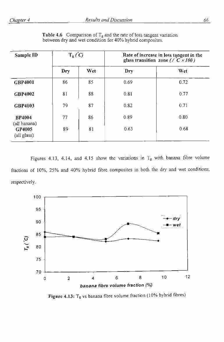
Chapter 4 Results and Discussion 66
Table 4.6 Comparison of Tg and the rate of loss tangent variation between dry and wet condition for 40% hybrid composites.
Sample ID
GBP4001
GBP4002
GBP4003
BP4004 (all banana)
GP4005 (all glass)
Tg ("Q
Dry
86
81
79
77
89
Wet
85
88
87
86
81
Rate of increase in loss tangent in the glass transition zone (/ C xlOO)
Dry
0.69
0.81
0.82
0.89
0.63
Wet
0.72
0.77
0.71
0.80
0.68
Figures 4.13, 4.14, and 4.15 show the variations in Tg with banana fibre volume
fractions of 10%, 25%) and 40% hybrid fibre composites in both the dry and wet conditions,
respectively.
» 80
2 4 6 8 10
banana fibre volume fraction (%)
Figure 4.13: Tg vs banana fibre volume fraction (10% hybrid fibres)

Chapter 4 Results and Discussion 67
0 10 15 20 banana fibre volume fraction (%)
25 30
Figure 4.14: Tg vs banana fibre volume fraction (25% hybrid fibres)
0 10 20 30 40
banana fibre volume fraction (%)
Figure 4.15: Tg vs banana fibre volume fraction (40% hybrid fibres)

Chapter 4 Results and Discussion 68
From Tables 4.4, 4.5 and 4.6, in dry condition, it can be noticed tiiat tiie all-glass fibre
composites have the highest inhial (dry) Tg compared to any other hybrid composites. Witii
increasing glass fibre content, Tg increases, from that of GP1005 (10%) all glass) to tiiat of
GP4005 (40%) all glass). In contrast, the all-banana fibre composite having 40%) fibre content,
BP4004, has the lowest initial Tg. In Figures 4.13, 4.14 and 4.15, the otiier hybrid composites lie
in between these two extremes. No significant change in the Tg is observed with different banana
and glass hybrid volume fractions, among the GBP 1000, GBP2500 and GBP4000 series samples.
It is interesting to note a general trend of increasing Tg with increasing banana fibre content in tiie
wet composites. This is presumably due to the phenomenon reported earlier by Satyanarayana
(1981) where the banana fibre stiffness increases over the initial stages of water absorption.
Although possibly counter-intuitive, it is proposed that this effect plays a significant role in the
wet-behaviour of the hybrid composites. As discussed briefly, although the glass transition
behaviour is normally thought to be controlled primarily by the matrix material, different Tg
behaviour exists between the all-glass and all-banana fibre reinforced materials. It is reasonable
to assume therefore, that any changes in mechanical properties of the banana fibres will be
reflected in a change in the overall Tg behaviour. In this case, the observed behaviour is likely
explained by the increased fibre stiffness in the wet state leading to greater reinforcement and
causing glassy behaviour to be maintained to higher temperatures than in the dry state.
The glass transition temperature of most of tiie hybrid composites fell in the narrow
temperature range of 8 1 ^ - 8 5 ^ . Composites fabricated from hybrid fibres may therefore be
expected to perform adequately in service conditions of high ambient temperature and high
humidity, such as those encountered in tiopical regions. The data indicate that the materials tested
o o
will remain glassy and stiff, even when wet, provided the temperature does not reach -81 C-85 C.

Chapter 4 Results and Discussion 69
The rate of increase in loss tangent of the hybrid composite is dependent on tiie
glass/banana fibre volume fraction. It can be observed that the rate of mcrease in loss tangent of
the all-banana fibre specimens is higher when dry than the other hybrid specimens. Witii tiie
addition of glass fibres the rate of increase in loss tangent decreases. When wet, the same
conclusion is true for most ofthe samples. Satyanarayana et al. (1984) reported that the banana
fibres are hygroscopic, and they are stiffened by water absorption to some degree. In fact, the
banana fibres or the fibre/matrix interfaces are influenced more by the presence of water than the
glass fibres. Therefore, when there are no glass fibres to damp out this effect, the influence is
most greatly felt.
Water absorption may generally decrease the glass transition temperature of fibre
reinforced composites (Springer 1982 and Selzer 1997 and Friedrich). From Tables 4.4, 4.5 and
4.6, it can be seen that Tg of all-glass reinforced composites (GP1005, GP2505 and GP4005)
decreases by 2 to 8 °C with water absorption. Tg of hybrid composites having more glass fibres
(GBPlOOl, GBP2501 and GBP4001) either remains the same or increases with water absorption.
With increasing banana fibre volume fraction, Tg of wet samples is higher than that of dry samples
for the GBP4000 series.

Chapter 4 Results and Discussion 70
4.2 STATIC MECHANICAL PROPERTIES
The flexural strength and flexural modulus of hybrid composites are given in Table 4.7.
The flexural strength was calculated using equation (2.3) after obtaining experimental values of
P̂ ax- The flexural modulus was calculated using equation (2.4).
Table 4.7 Static mechanical properties of hybrid composites.
Sample ID
GBPlOOl
GBP1002
GBP1003
BP1004
GP1005
GBP2501
GBP2502
GBP2503
BP2504
GP2505
GBP4001
GBP4002
GBP4003
BP4004
GP4005
Density
(g/cm')
1.13
1.09
1.06
1.04
1.13
1.10
1.09
1.06
1.02
1.24
1.19
1.14
1.12
1.01
1.32
Water absorptioc (%)
(24 hours at room temperature)
1.72
3.46
3.76
6.86
1.28
1.69
3.17
7.86
15.74
1.45
4.17
4.82
9.82
20.13
2.94
Flexural strength (MPa)
Dry
81.40
37.40
34.79
34.49
108.89
135.69
102.40
74.31
19.35
169.54
114.08
74.44
49.23
13.81
165.54
Wet
62.88
42.03
30.85
25.18
95.44
134.2
75.94
63.12
18.48
168.20
119.43
59.65
24.05
10.52
125.47
Flexural modulus (GPa)
Dry
2.76
2.47
2.04
1.59
3.41
4.34
3.48
2.13
0.90
4.71
5.97
2.41
1.59
0.56
6.18
Wet
2.69
2.27
1.72
1.58
3.10
3.39
2.67
1.20
0.90
4.08
4.23
1.29
0.70
0.20
4.35

Chapter 4 Results and Discussion 71
Figures 4.16, 4.17 and 4.18 show the variation in flexural stiength with banana fibre
volume fractions of 10%), 25% and 40%), respectively, in both dry and wet conditions. The
variation in flexural modulus with banana fibre volume fractions is given in Figures 4.19. 4.20
and 4.21. Again, the influence of the increased stiffness observed with wet banana fibres as
reported by Satyanarayana (1981) is seen. This is particularly prevalent in the case ofthe high
fibre content composites in Figure 4.21, where the initial gap in stiffriess between wet and dry
materials is less pronounced for higher banana fibre contents. The water absorption vs. banana
fibre volume fraction is illustrated in Figures 4.22, 4.23 and 4.24 over 10%), 25%o and 40%) hybrid
fibres in both dry and wet conditions.
2 4 6 8 10
banana fibre volume fraction (%)
Figure 4.16: The flexural strength vs banana fibre volume fraction (10%) hybrid fibres)

Chapter 4 Results and Discussion 12
0 10 15 20 25 30
banana fibre voliMne fraction f^ Figure 4.17: The flexural s trer^ vs banana fibre volume
fiactioiK25% hybdd fibres)
200
10 20 30 40
banana fibere volume fraction (%)
Figure 4.18: The flexural strength vs banana fibre volume fraction (40% hybrid fibres)

Chapter 4 Results and Discussion 73
4 6 8
banana fibre volume fraction (%)
10
Figure 4.19: The flexural modulus vs banana fibre volume fraction (10% hybrid fibres)
0 5 10 15 20 25
banana fibre volume fraction (%)
Figure 4.20: The flexural modulus vs banana fibre volume
fiaction (25%) hybrid fibres)

Chapter 4 Results and Discussion
10 20 30 40
banana fibre volume fraction (%) F^ure 4.21: The flexural modulus vs banana fibre volume
fi-action (40% hybrid fibres)
50
0 2 4 6 8 10
banana fibre volume fraction (%)
Figure 4.22: Water absorption vs banana fibre volume fi-action (10% Itybrid fibres)

Chapter 4 Results and Discussion 75
0 10 15 20
banana fibre volume fraction (%)
25 30
Figure 4.23: Water absorption vs banana fibre volume fraction (25%) hybrid fibres)
0 10 20 30 40
banana fibre volume fraction (%)
Figure 4.24: Water absorption vs banana fibre volume fraction (40%) hybrid fibres)

Chapter 4 Results and Discussion
From Table 4.7, it is seen that the flexural strength and modulus mcrease witii h\'brid fibre
content from \0% to 25%). All-glass fibre composites have higher value of both stiength and
modulus. The strength of banana fibres is considerably less than that of glass fibres, so that with
addition of banana fibre in hybrid composites, the strength and modulus of hybrid composites
decrease. This is most obvious in the 40%) hybrid group.
A similar effect of water absorption to that shown in dynamic and static mechanical
behavior is also observed with the static properties. The flexural strength and modulus of all
hybrid composites decreases with water absorption. The biggest change in modulus value is
observed in 40%) hybrid fibre composites, as seen in Figure 4.21. From Figures 4.22, 4.23, and
4.24, the amount of water absorption in hybrid composhes increases with addition of banana
fibres. In Table 4,7, the hybrid composites having more banana fibres have lower density
compared with those having more glass fibres.
In Figures 4.25 to 4.30, load deflection curves are given for 10% to 40% hybrid
composites. Although the inclusion of banana fibres causes a slight deterioration in properties of
hybrid composites, this deterioration is certainly not so significant as to preclude these hybrid
composites' use in certain applications, such as inexpensive building materials for developing
tropical countries. The addhion of banana fibres brings the benefit of low cost and low density(as
shown in Table 4.7) for this service condition.
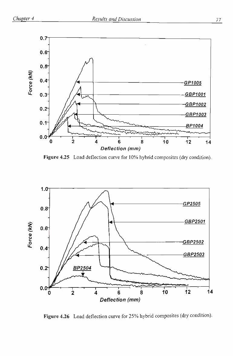
Chapter 4 Results and Discussion 17
if
0.7
o.e-
GP1005
.GBP1001
-GBP1002
GBP1003
BP1004
4 6 8 Deflection (mm)
Figure 4.25 Load deflection curve for 10%) hybrid composites (dry condition).
1.0
I Q)
4 6 8 Deflection (mm)
GBP2501
Figure 4.26 Load deflection curve for 25% hybrid composites (dry condition).

Chapter 4 Results and Discussion 78
I
GP4005
GBP4001
GBP4002
^ A ^ ^ M ^ ^ M ^ ^ ^ ^ M
6 8 Deflection (mm)
10 12 14
Figure 4.27 Load deflection curve for 40%o hybrid composites (dry condition).
0.7
Deflection (mm)
GP1005
GBP1001
-GBP1002
_BP1004
Figure 4.28 Load deflection curve for 10% hybrid composites (wet condhion).

Chapter 4 Results and Discussion 79
1.2
I £
GP2505
GBP2501
GBP2503
GBP2502
Deflection (mm)
Figure 4.29 Load deflection curve for 25%) hybrid composites (wet condition).
o.a
I § 0.^ £
6 8 Deflection (mm)
1— 10
GBP4001
GP4005
GBP4002
Figure 4.30 Load deflection curve for 40% hybrid composhes (wet condition).

Chapter 5
Conclusions
The banana-glass hybrid fibre reinforced polyester composite materials were fabricated.
Techniques for the fabrication of hybrid composites have been reported.
The dynamic mechanical analysis techniques have been used to investigate the effect of
temperature and absorbed moisture on the dynamic mechanical properties of glass-banana hybrid
fibre composites. Dynamic mechanical analysis testing conducted in the temperature scan mode,
using a dynamic mechanical analyzer, was effective in characterizing the hybrid fibre composites
over a wide temperature range. The following conclusions can be drawn from the data:
1) Dynamic mechanical analysis, which requires small sized samples, can provide
sensitive insight into the behavior of hybrid composite materials over a wide temperature range.
2) The dynamic mechanical behavior exhibited by the hybrid fibre composite materials at
room temperature is not representative of their characteristics at higher temperature. The
degradation in flexural storage modulus with higher temperature is qmte apparent. Also, there is
significant variation in loss tangent at higher temperatures.

Chapter 5 Conclusions 81
3) The flexural storage modulus exhibited by the hybrid composites is dependent on
hybrid fibre volume fraction. With increasing glass fibre content, the storage modulus increases.
In contrast, with increasing banana fibre content the storage modulus decreases.
4) In general, the rate of change in flexural modulus and loss tangent (in the glass
transition zone) is found to be dependent on the hybrid fibre contents, glass fibre and banana fibre
volume fractions.
5) The storage modulus exhibited by the hybrid fibre composites is reduced imder the wet
conditions. Although the banana fibre stiffness increases by water absorption, the fact that this
increase in stiffness is not reflected in the mechanical properties ofthe composite material leads to
the conclusion that the interfacial strength is compromised by the absorption of water. The effect
of interfacial bond strength between fibre and matrix dominates over the gains in fibre stiffness
brought about by water absorption.
6) Stiffness of the hybrid composite materials decreases with increased banana fibre
content, and wet stiffness is generally less than dry stiffness. At higher banana fibre contents, the
wet stiffness of the materials does not decrease at the same rate as that in the dry materials with
increased banana fibre content, indicating that the wet stiffening effect begins to contribute to an
enhancement of mechanical properties.
7) All-glass fibre reinforced composites have the highest glass transition temperature and
all-banana fibre reinforced composites have the lowest glass transition temperature. No
significant improvement in the glass transition temperature is observed with different hybrid fibre
contents.
The investigation of static flexural test was carried out to determine the rigidity of hybrid
fibre composite materials. The static properties of hybrid composites do not appear to deteriorate

Chapter 5 Conclusions 82
to a significant degree under the wet conditions
This study suggests that it is possible to fabricate natural fibres such as banana fibres and
glass fibre hybridization into composites with polyester resin. Although these composites exhibit
lower strength and stiffness than all-glass fibre reinforced composites, they possess comparable
stiffness, competitive costs and lower overall density. Based on the presented investigation, it is
expected that these composites could find applications in the following areas, low cost housing,
emergency shelter materials following natural disasters, packaging for transportation purposes and
manufacturing of consumable goods that require light weight, such as golf clubs, tennis rackets
and kayaks.

Chapter 6
Recommendations for Future Work
Although the aim of this project has been reached to investigate the dynamic mechanical
behavior of hybrid composites, some potentially interesting aspects of this work are expected to
provide future work and more complete understanding.
Other natural fibres such as abaca, bamboo fibres and rice husk are stiongly recommended
for hybrid fibre reinforced composite. Dynamic and static mecharucal properties can be
investigated for comparison between them.
Composites made from continuous natural fibres could have greater strength than those
with short fibres. Fibre orientation in the matrix also determines the mechanical strength of the
composites and the direction in which that stiength will be the greatest. The composites made
from shorter fibres, if the fibres could be properly oriented, could have substantially greater
stiength than those made from continuous fibres. This aspect can be investigated.

Chapter 6 Recommendations for future work 84
The type of hybrid composite material is one of the factors which affects the dynamical
and static mechanical behavior of hybrid composites. Only one type of hybrid composite has
been tested during the current work. The variation of flexural modulus and loss tangent with
temperature probably are dependent on the fibre lay-up sequence. For example, the natural fibre
layer may be put as the inner glass fibre layer or outer glass fibre layer.
It is thought that a more thorough theoretical understanding of system behavior would be gained
through a more systematic evaluation of the wet and dry performance of the composites tested.
The data generated in this study focused on the differences in performance between wet and dry
materials, but it did not address issues of dynamic water absorption or the effect of repeated
wet/dry cycles. It is thought that a study of the relationship between water absorption and
properties across the entire spectrum of water contents possible in this and other systems would
prove instructive.
A consideration should be given to the development of theoretical modeling to predict
properties of hybrid fibre composites based on an understanding of fibre and matrix and their
inter-relationship. Modeling allows the engineer to indicate tiie direction for future work in
achieving optimum system parameters.

References
Agarwal, BH. and Broutman LJ. 'Analysis and performance of fibre composites', New York, John Wiley and sons (1980)
American Society for Metal (ASM), 'Engineer guide to composite materials', OH, USA, Carnes Publication Services (1990)
Bunsell, AR. 'Fibre reinforcements for composite materials'. New York, Elsevier Science Publishers i\9SS)
Cahn, RW. 'Structure and properties of composites', Materials Science and Technology, Volume 13(1990)56-67
Campbell, D. and White, JR. 'Polymer characterization: Physical technology', London, Chapman and Hall (\9S9)
Cassel, B. and Twombly, B. 'Material characterization by thermomechanical analysis', PA, USA, ASTM (1991) 108-119
Chang, SC, Tai NH, Chen, C. and Ma, M. Journal of Materials Science 30 (1995) 1225-1232
Chou, TW. 'Microstructural design of fibre composites', London, Cambridge University Press (1992)
Coutts, RSP. and Warden, PG. 'Air-cured, wood pulp, fibre cement composites' Journal of Materials Science Letters 4 (1985) 117-119
References 86
Coutts, RSP. 'Banana fibres as reinforcement for building products', Journal of Materials Science Letters 9(1990)1231-1242
DMA7 Manual, Perkin Elmer (1995)
Eckold, G. 'Design and manufacture of composite structures', London, Woodhead Publishing Ltd (1994)
Ferry, JD. 'Viscoelastic properties of polymers', 3''' editon. New York, John Wiley & Sons (1980)
Folks, MJ. 'Short fibre reinforced thermoplastics', London, Research press (1982)
Fordos, Z. 'Natural or modified cellulose fibres as reinforcement in cement composite', Glassgow and London, Blackie and Son LTD (1988) 173-206
Gibson, RF. 'Principles of composite material mechanics', New York, McGraw-Hill Inc (1994)
Grayson, M. 'Encyclopedia of composite materials and components', New York, A Wiley-Interscience Publication (1983) 373-375
Haddad, SM. 'Viscoelasticity of engineering materials', London, Chapman and Hall {\995)
Hancox, NL. 'Fibre composite hybrid materials', London, Applied Science Publishers LTD
(1981)
Himmelfarb, D. 'The technology of cordage, fibres and rope', London, Leonard Hill Books (1957)
Kelly, A. 'Concise of composite: concise encyclopedia materials', London, Pergamon Press
(1984)
Kretsis, G. 'A review ofthe tensile, compressive, fiexural and shear properties of hybrid fibre reinforced plastics' Composites volume 18 NO 1(1987) 13-22
Kulkarni, AG. Satyanarayana, KG. Rohatgi, PK. Vijayan, K. 'Mechanical properties of banana fibres(musa sepientume)', Journal of Material Science, 1(1983) 2290-2296.

References 8'
Mallick, PK. 'Fibre-reinforced composites-materials, manufacturing and design', New York Marcel Dekker (\9SS)
Matthews, FL. and Rawings RD. 'Composite materials: Engineering and Science ', Chapman and Hall (1994)
Mickels, N. 'Banana collins encyclopedia', 3 (1990) 540
Nielsen, LE. 'Mechanical properties of polymers and composites', New York, Marcel Dekker (1994)
Potter, K. 'An introduction to composites products', London, Chapman and Hall (1997)
Qureshi, HA. 'The design and development of automotive body from natural fibre reinforced composites', ¥' international conference on composites engineering (1997) July 95-96
Satyanarayana, KG., Sukumaran, K., Mukherjee, PS., Pavithran, C. and Pillai, SGK. 'Possibility of using natural fibre composites as building materials', Roorki, India, Proc International Conference on Low Cost Housing for Developing Country on Composite Structure, (1984) 177-181
Satyanarayana, KG., Sukumaran, K., Kulkarni, AG., Pillai, SGK. and Rohatgi, PK. Composites (1986) Volume 17 N04 329-333
Satyanarayana, KG., Sukumaran, K., Mukherjee, PS., Pavithran, C. and Pillai, SGK. Cement & Concrete Composites (1990) 12 117-136.
Scwartz, MM. 'Composite materials handbook'. New York, Mcgraw-Hill Book Company (1984)
Selzer, R. and Friedrich, K. Composites part A (1997) 28A 595-604
Sepe, MP. 'The use of dynamic mechanical analysis in the characterization of composite materials', 4'^ International Conference on Composite Engineering (1997) July 871
Sheldon, RP. 'Composite polymeric materials', USA, Applied Science Publishers (1986)

References 88
Springer, GS. 'Developments in reinforced plastics-2', London, Applied Science Publishers (1982)43-65
Tobias, BC. 'Development of organic fibre-reinforced composite materials', California, USA, Science of Advanced Materials and Process Engineering Series, book I (of 2) (1987) 211-221
Ward, I.M. 'Mechanical properties of solid polymer', London, A Wiley Inter science Publication (1971)
Warring, RH. 'The glass fibre handbook', London, Nexus Special Interests (1993)
Wolff, EG. SAMPE Journal (1993) Volume 29 NO 3 11-19
Zhu, WH. M.S. thesis, 'Utilisation of banana fibre in composite materials', Victoria University, VIC, Australia (\99A)
