!! master stair jig - · pdf filepage 4 !!! staircase design!!! the number of steps in the...
TRANSCRIPT
Page 1
Titman Tip Tools Limited: Valley Road, Clacton-on-sea, Essex, CO15 6PP, UK
T: +44 (0)1255 220123 F: +44 (0)1255221422 E: [email protected] W: www.titman.co.uk
Master Stair Jig Instruction Leaflet
Page 2
INTRODUCTI ON
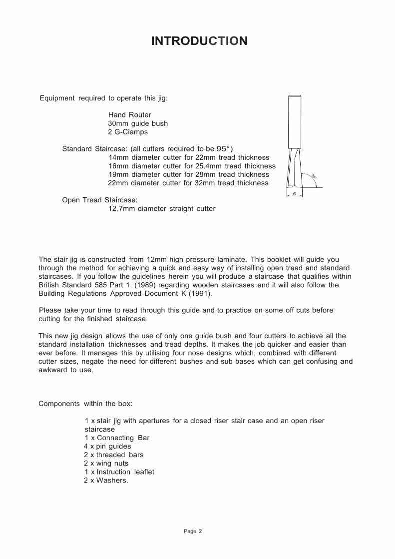
Equipment required to operate this jig:
Hand Router 30mm guide bush 2 G-Ciamps
Standard Staircase: (all cutters required to-be 95°)
14mm diameter cutter for 22mm tread thickness 16mm diameter cutter for 25.4mm tread thickness 19mm diameter cutter for 28mm tread thickness 22mm diameter cutter for 32mm tread thickness
Open Tread Staircase:
12.7mm diameter straight cutter The stair jig is constructed from 12mm high pressure laminate. This booklet will guide you through the method for achieving a quick and easy way of installing open tread and standard staircases. If you follow the guidelines herein you will produce a staircase that qualifies within British Standard 585 Part 1, (1989) regarding wooden staircases and it will also follow the Building Regulations Approved Document K (1991). Please take your time to read through this guide and to practice on some off cuts before cutting for the finished staircase. This new jig design allows the use of only one guide bush and four cutters to achieve all the standard installation thicknesses and tread depths. It makes the job quicker and easier than ever before. It manages this by utilising four nose designs which, combined with different cutter sizes, negate the need for different bushes and sub bases which can get confusing and awkward to use.
Components within the box:
1 x stair jig with apertures for a closed riser stair case and an open riser staircase 1 x Connecting Bar 4 x pin guides 2 x threaded bars 2 x wing nuts 1 x Instruction leaflet 2 x Washers.
Page 3
STAIRCASE PARTS
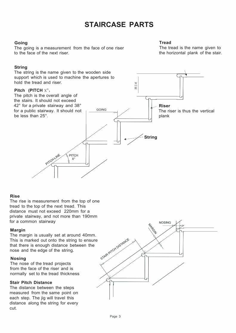
Going The going is a measurement from the face of one riser to the face of the next riser.
Tread The tread is the name given to the horizontal plank of the stair.
String The string is the name given to the wooden side support which is used to machine the apertures to hold the tread and riser.
Pitch (PITCH X0 )
The pitch is the overall angle of the stairs. It should not exceed 42° for a private stairway and 38°
w (/)
oc
Riser
for a public stairway. It should not be less than 25°.
GOING The riser is thus the vertical plank
String
Rise The rise is measurement from the top of one tread to the top of the next tread. This distance must not exceed 220mm for a private stairway, and not more than 190mm for a common stairway
Margin The margin is usually set at around 40mm. This is marked out onto the string to ensure that there is enough distance between the nose and the edge of the string.
Nosing The nose of the tread projects from the face of the riser and is normally set to the tread thickness
Stair Pitch Distance The distance between the steps measured from the same point on each step. The jig will travel this distance along the string for every cut.

Page 4
STAIRCASE DESIGN
The number of steps in the staircase is governed by the floor to floor height as this is a fixed distance, and the distance available for the going.
Normal values for the rise range between 170mm and 200mm high.
In order to work out the exact value you must first find a suggested value. For example lets say the rise is 180mm (the distance from one tread to the next tread).
So, if the total going of flight (floor to floor height) is 2500mm we can work out: 2500/180 = 13.88 steps.
Obviously we have to have a whole number for the number of steps so try 14. The calculation is tried again, dividing the number of steps by the total rise of flight , 2500/14 = 178.6mm
So the value of each rise is exactly 178.6mm high. The value of the going should not be less than 220mm fro a private stairway and no less than 240mm for a common stairway. For this example the going will be 250mm.
To work out the exact distance for the total going of flight multiply the number of steps minus one by the going, for example 13 x 250 = 3250mm If the total going of flight value is longer than the space you have to fit the staircase then try some smaller going eg.220mm.
Rise of step (EG 178.6mm) GOING OF STEP (EG. 250mm)
TOTAL GOING OF FLIGHT (EG. 3250)
Total rise of flight (EG 2500mm)
OPERATION
Page 5
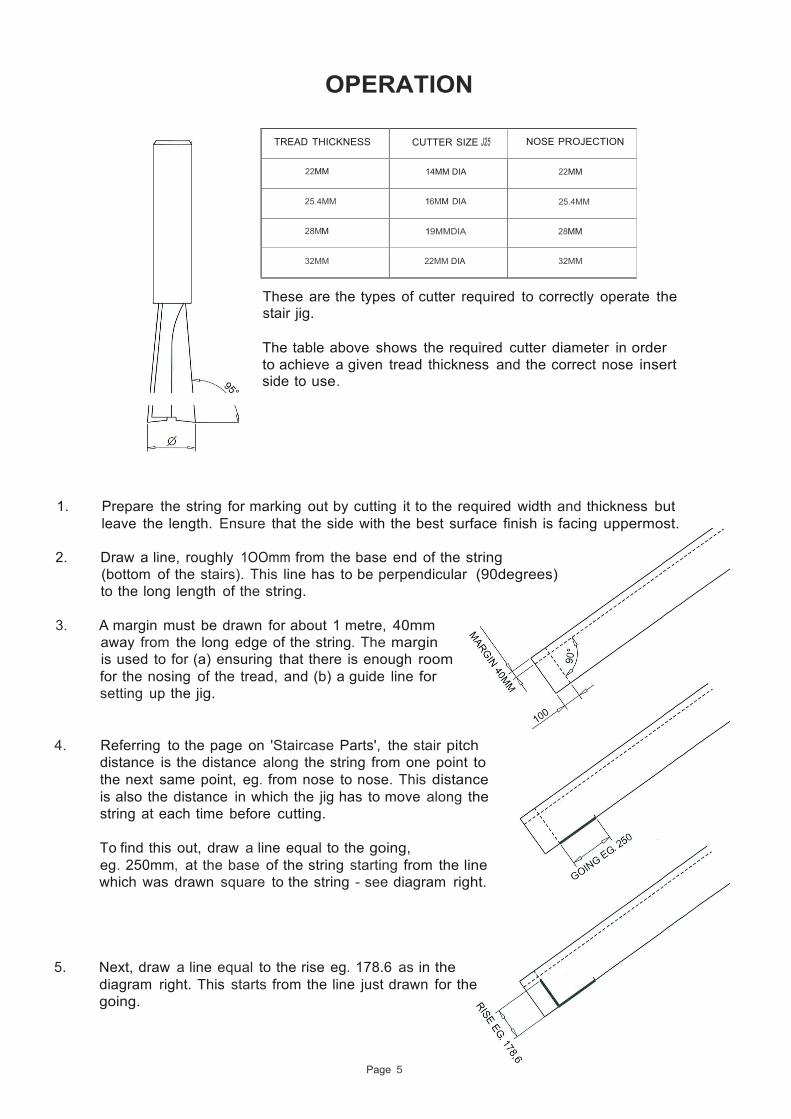
TREAD THICKNESS CUTTER SIZE J25
NOSE PROJECTION
22MM
14MM DIA
22MM
25.4MM
16MM DIA
25.4MM
28MM
19MMDIA
28MM
32MM
22MM DIA
32MM
These are the types of cutter required to correctly operate the stair jig.
The table above shows the required cutter diameter in order to achieve a given tread thickness and the correct nose insert side to use.
1. Prepare the string for marking out by cutting it to the required width and thickness but leave the length. Ensure that the side with the best surface finish is facing uppermost.
2. Draw a line, roughly 1OOmm from the base end of the string
(bottom of the stairs). This line has to be perpendicular (90degrees) to the long length of the string.
3. A margin must be drawn for about 1 metre, 40mm
away from the long edge of the string. The margin is used to for (a) ensuring that there is enough room for the nosing of the tread, and (b) a guide line for setting up the jig.
4. Referring to the page on 'Staircase Parts', the stair pitch distance is the distance along the string from one point to the next same point, eg. from nose to nose. This distance is also the distance in which the jig has to move along the string at each time before cutting.
To find this out, draw a line equal to the going, eg. 250mm, at the base of the string starting from the line which was drawn square to the string - see diagram right.
5. Next, draw a line equal to the rise eg. 178.6 as in the diagram right. This starts from the line just drawn for the going.
OPERATION
Page 6
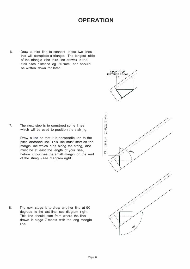
6. Draw a third line to connect these two lines - this will complete a triangle. The longest side of the triangle (the third line drawn) is the stair pitch distance eg. 307mm, and should be written down for later.
7. The next step is to construct some lines which will be used to position the stair jig.
Draw a line so that it is perpendicular to the pitch distance line. This line must start on the margin line which runs along the string, and must be at least the length of your rise, before it touches the small margin on the end of the string - see diagram right.
8. The next stage is to draw another line at 90 degrees to the last line, see diagram right. This line should start from where the line drawn in stage 7 meets with the long margin line.
;;:: z 'i: c ;;:: ::0 Ui m 0 Ui z () m m 0
OPERATION
Page 7
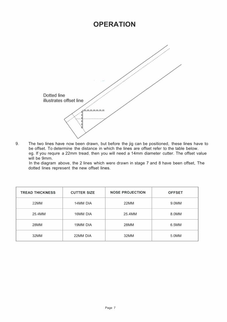
9. The two lines have now been drawn, but before the jig can be positioned, these lines have to
be offset. To determine the distance in which the lines are offset refer to the table below. eg. If you requre a 22mm tread, then you will need a 14mm diameter cutter. The offset value will be 9mm. In the diagram above, the 2 lines which were drawn in stage 7 and 8 have been offset, The dotted lines represent the new offset lines.
TREAD THICKNESS
CUTTER SIZE
NOSE PROJECTION
OFFSET
22MM
14MM DIA
22MM
9.0MM
25.4MM
16MM DIA
25.4MM
8.0MM
28MM
19MM DIA
28MM
6.5MM
32MM
22MM DIA
32MM
5.0MM

Page 8
OPERATION
:
10. Line up the jig perfectly with the two offset lines as shown in the diagram below. Clamp the jig firmly in position before moving to the next step.
LINE UP WITH DOTTED LINE
11. Attach the guide pins into the slots in the jig (see below) and push the guide pins firmly
against the edge of the string. Tighten the pins in position. Place the connecting bar over the guide pins. Tighten the connecting bar onto the guide pins - once attached this will also rest against the edge of the string. When the opposite side of the string is machined out the jig has to be turned over to its opposite face - when releasing the connecting bar, the guide pins will remain in position, therefore keeping the correct pitch angle which saves all the initial setting up.
Wingnut
(,§)--Washer
Guide Pin
I
,.... I ... ,
( f......J 'i 1: '..... ....... ....... ;I
Il i_ ...."
/ Jig Face
' I ,.- '-. ... ,_!.,1.,..""
I I I I I I l _)
OPERATION
Page 9
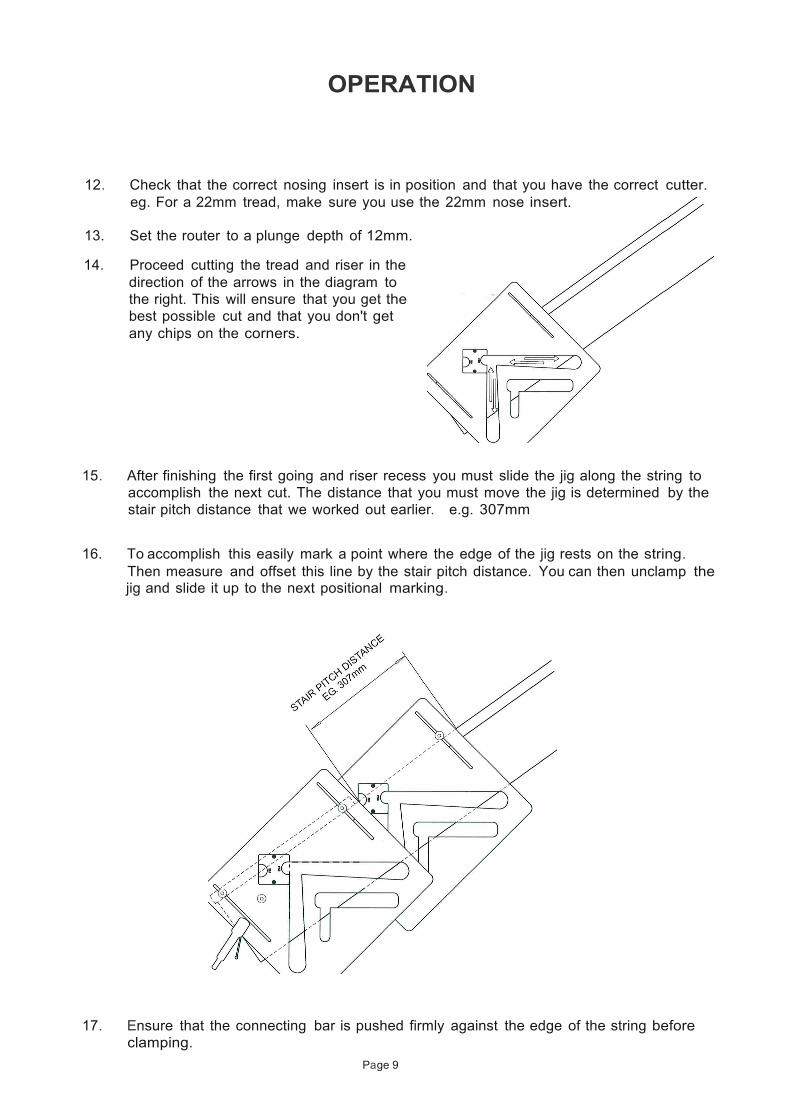
12. Check that the correct nosing insert is in position and that you have the correct cutter. eg. For a 22mm tread, make sure you use the 22mm nose insert.
13. Set the router to a plunge depth of 12mm.
14. Proceed cutting the tread and riser in the
direction of the arrows in the diagram to the right. This will ensure that you get the best possible cut and that you don't get any chips on the corners.
15. After finishing the first going and riser recess you must slide the jig along the string to
accomplish the next cut. The distance that you must move the jig is determined by the stair pitch distance that we worked out earlier. e.g. 307mm
16. To accomplish this easily mark a point where the edge of the jig rests on the string.
Then measure and offset this line by the stair pitch distance. You can then unclamp the jig and slide it up to the next positional marking.
17. Ensure that the connecting bar is pushed firmly against the edge of the string before
clamping.
Page 10
OPERATION
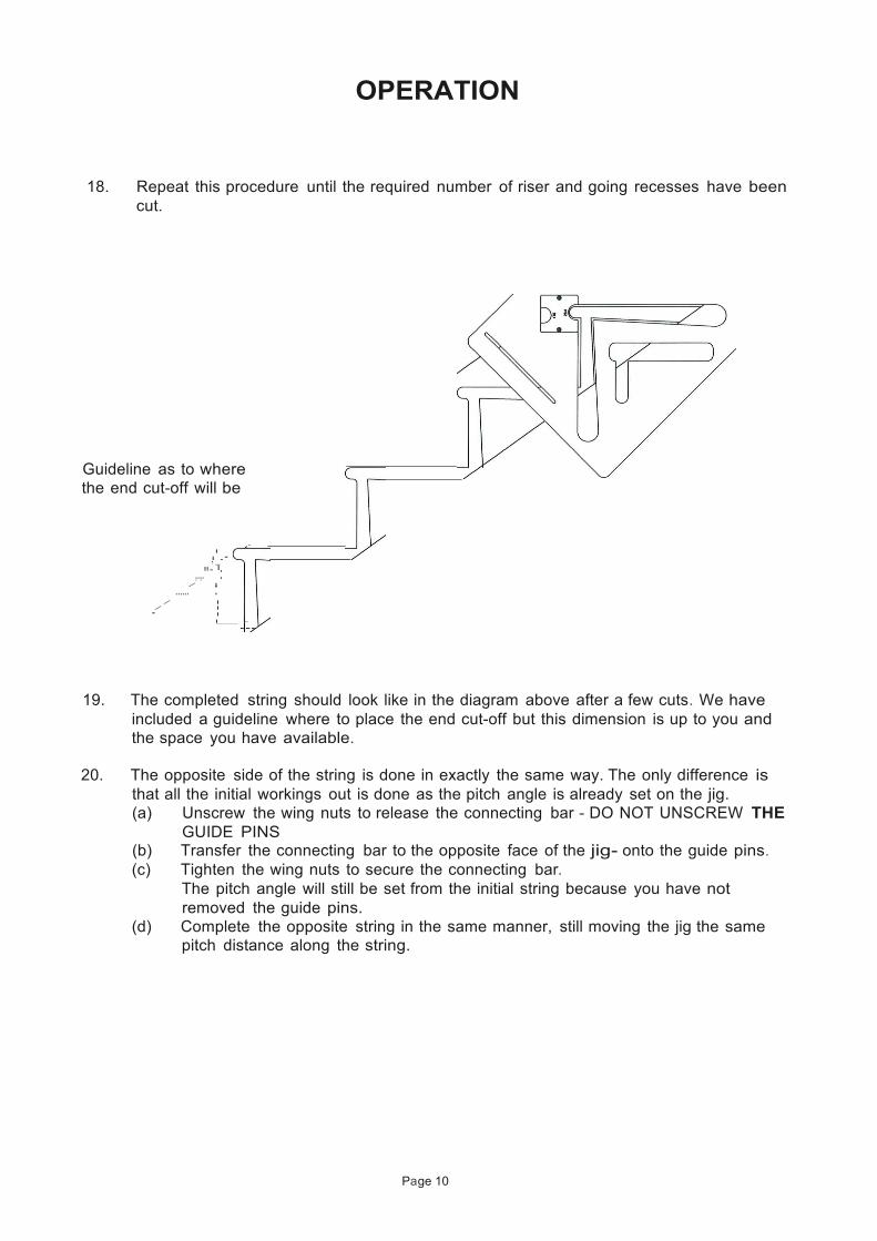
18. Repeat this procedure until the required number of riser and going recesses have been cut.
Guideline as to where the end cut-off will be
I I, _-'
,.,."', 1: ....../ I:
/ I / I ' I
I -
19. The completed string should look like in the diagram above after a few cuts. We have included a guideline where to place the end cut-off but this dimension is up to you and the space you have available.
20. The opposite side of the string is done in exactly the same way. The only difference is
that all the initial workings out is done as the pitch angle is already set on the jig. (a) Unscrew the wing nuts to release the connecting bar - DO NOT UNSCREW THE
GUIDE PINS (b) Transfer the connecting bar to the opposite face of the jig- onto the guide pins. (c) Tighten the wing nuts to secure the connecting bar.
The pitch angle will still be set from the initial string because you have not removed the guide pins.
(d) Complete the opposite string in the same manner, still moving the jig the same pitch distance along the string.
Page 11
OPEN RISER STAIR JIG
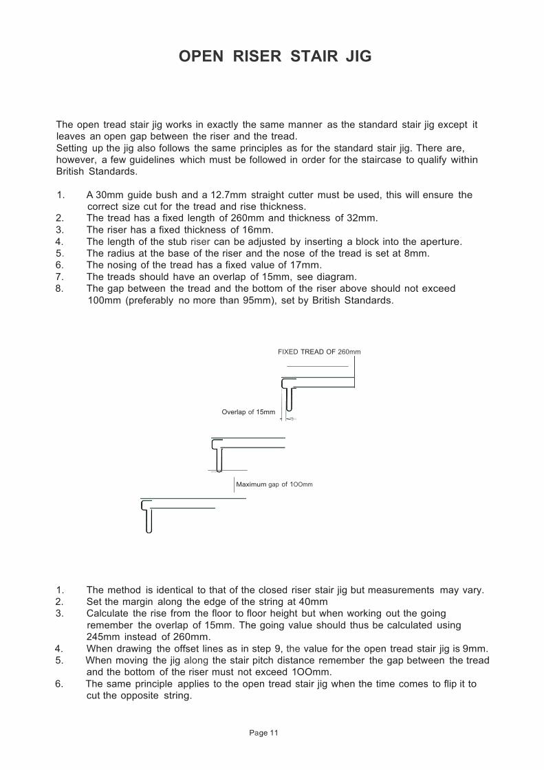
The open tread stair jig works in exactly the same manner as the standard stair jig except it leaves an open gap between the riser and the tread. Setting up the jig also follows the same principles as for the standard stair jig. There are, however, a few guidelines which must be followed in order for the staircase to qualify within British Standards.
1. A 30mm guide bush and a 12.7mm straight cutter must be used, this will ensure the
correct size cut for the tread and rise thickness. 2. The tread has a fixed length of 260mm and thickness of 32mm. 3. The riser has a fixed thickness of 16mm. 4. The length of the stub riser can be adjusted by inserting a block into the aperture. 5. The radius at the base of the riser and the nose of the tread is set at 8mm. 6. The nosing of the tread has a fixed value of 17mm. 7. The treads should have an overlap of 15mm, see diagram. 8. The gap between the tread and the bottom of the riser above should not exceed
100mm (preferably no more than 95mm), set by British Standards.
FIXED TREAD OF 260mm
Overlap of 15mm
Maximum gap of 1OOmm
1. The method is identical to that of the closed riser stair jig but measurements may vary. 2. Set the margin along the edge of the string at 40mm 3. Calculate the rise from the floor to floor height but when working out the going
remember the overlap of 15mm. The going value should thus be calculated using 245mm instead of 260mm.
4. When drawing the offset lines as in step 9, the value for the open tread stair jig is 9mm. 5. When moving the jig along the stair pitch distance remember the gap between the tread
and the bottom of the riser must not exceed 1OOmm. 6. The same principle applies to the open tread stair jig when the time comes to flip it to
cut the opposite string.