ledigital.lib.lehigh.edu/fritz/pdf/249_29.pdf · le fritz eng!neering laioratory library. i. welded...
TRANSCRIPT
Fritz Engineering Laboratory Report Of> 2 9@2
byLambert Tall
IL ·
elded Built-Up olumnl
LE
FRITZ ENG!NEERINGLAiORATORY LIBRARY.

I.
Welded Built-Up Columns
WELDED BUILT-UP COLUMNS
by
Lambert Tall
Fritz Engineering LaboratoryDepartment of Civil Engineering
Lehigh UniversityBethlehem, Pennsylvania
April 1966
Fritz Laboratory Report No. 249.29

249.29
1.
2.
3.
4.
5.
6.
7 •
8.
TABLE OF CONTENTS
ABSTRACT
INTRODUCTION
RESIDUAL STRESSES AND MECHANICAL PROPERTIES
2.1 FORMATION
2.2 WELDED PLAtES AND WELDED SHAPES
2.3 THEORETICAl STUDIES
2.4 MECHANICAL PROPERTIES
COMPRESSION MEMBERS
3.1 RESIDUAL STRESSES AND COLUMN BUCKLING
3 •2 WELDED COLUMNS
3.3 FACTORS IN COL1~ STRENGTH
304 REINFORCED COLUMNS AND HYBRID COLUMNS
3 .5 HEAVY COLUMNS AND FLA:ME-CUT PLATES
3.6 WIDTH-THICKNESS RATIOS AND PLATE BUCKLING
3.7 DESIGN IMPLICATIONS
SUMMARY
ACKNOWLEDGEMENTS
NOMENCLATURE
TABLES AND FIGURES
REFERENCES
Page
1
4
4
5
11
15
18
19
21
25
27
30
32
34
36
42
43
45
88

249.29
1. INTRODUCTION
A research project on the "Strength of Welded Built-Up
Columns" has been in progress at Lehigh University under the guidance
of Task Group I of the Column Research Council. This Task Group origi
nally was assigned the task of determining the relationship between
material properties and the strength of columns. The early studies
were concerned with rolled columns, leading to a number of reports of
which References 1 and 2 were the preliminary report and the summary
report respectively.
The attention of the Task Group was directed towards welded
columns in 1959, and this report represents a summary of the findings
from that time through 1965, as well as a discussion of their signifi
cance. These welded columns were fabricated from TIM plates and were
from 6" x 6" to 10" X 10" in size with platep from 3/8" to 3/4" thick
ness. More recently, pilot investigations have commenced on welded
shapes which are fabricated from flame-cut plates, or from thick
plates. This recent work and its preliminary conclusions are des
cribed briefly.
Perhaps the most important findings of the previous studies
were concerned with the significance of the influence of residual
stresses on column strength. Based upon these ideas, and using the
tangent modulus concept for the buckling of inelastic columns, a
-1-

249.29 -2-
column strength curve was prepared by the Column Research Council for
rolled columns of ASTM A7 steel, and this column curve was adopted as
the design curve for all columns by the American Institute of Steel
Construction in 1961, with the inclusion of a suitable factor of
safety.
Figure 1 shows diagrammatically how the column curve depends
on the residual stress distribution. The stress-strain relationship
*obtained from the stub column test reflects the presence of residual
stresses. This is evident from Figo la where, for any fiber, when the
sum of the applied stress and the compressive residual stress acting on
that fiber becomes equal to the yield stress, yielding will commence in
that fiber. The beginning of yielding implies that the stress-strain
relationship for the complete cross section is no longer linear, or
elastic, as would be the case for a coupon, since a coupon contains no
residual stresses.
The column curve in Fig. ld results from the use of the stress-
strain relationship (Fig. lb) and the tangent modulus concept for buck~
ling. The tangent modulus curve (Fig. lc) may be used in the computa-
tion of column strength.
Reference is made throughout to the various progress reports
that contain the detailed experimental and theoretical work.
* The stub column test is an important control test in experimental investigation of columns, and is described further in Ref. 3.
249.29 -3-
Although simple, pinned-end columns do not occur in practice,
they must be regarded as the basic column, since all column specifica
tions (including those of beam-columns) are in terms of such a column.
Thus, the scope of this study is limited to centrally loaded columns,
generally of ASTM A7 or A36 steel, but with some information for other
grades also.

249.29
2 0 RESIDUAL STRESSES AND :MECHANICAL PROPERTIES
Although residual stresses have been studied for many years,
it is only in the past decade that it was realized that they are a
major influence in the strength of compression members, both columns
and plates. This had lead to a rather complete study of their forma-
tion, magnitude and distribution, and their effect on engineering
(1 2 4)structures. "
Residual stresses exist in rolled, welded, and cold-straight-
erred structural shapes. Their removal by annealing is costly and some-
times impossible, but a control over their influence is possible to
achieve.
The study of residual stresses and the strength of columns
has necessitated a study of the mechanical properties of the material
used. Some of the findings are reported here.
2.1 FORMATION
Residual stresses are formed in a structural member as a re-
sult of uneven relaxation of plastic deformations; they are stresses
which exist in the cross section even before the application of an
external load o This relaxation may be due to cooling after hot-rolling
or welding, or due to fabrication operations such as cold-bending or cam-
bering. Because of the localized heat input of welding, the relaxation of
the plastic deformations in welded shapes always occurs during the process
-4-

-5-
of cooling from the welding temperature to air temperature; the plastic
deformations result from the fact that some parts of the shape cool much
more rapidly than others, causing inelastic deformations in the slower
cooling portions.
2 a 2 WELDED PLATES AND WElDED SHAPES
The scope of this section, and of this report, is limited to
"thin" plates no greater than I" in thickness, and to "small" size
shapes 0 Some preliminary data from a pilot study is presented for
"thick" plates and for "heavy" shapes. Both the manual shielded-arc
and the automatic submerged-arc welding processes were considered for
plates and shapes 0
The two shapes which may be regarded as basic are the H-shape
and the box-shape, Fig$ 2 0 These shapes are made up of welded plates
which are either center-welded or edge-welded. It has been shown(5)
that the residual stress distribution in a welded shape is similar to
the separate residual stress distributions of ~he component welded\
plates o The statement is true for shapes made up of thin plates simi-
lar in size o This means that the residual stress distribution can be
estimated to within 10% for most welded shapes without recourse to
actual measurements 0 (5)
Plates
In both plates and shqpes, the residual stresses of prime
interest for structural purposes are the longitudinal residual stresses a

249.29
The "method of sectioningll(l) was used to measure the stresses; the
plates used were-sufficiently long so that a uniform state of stress
would exist in the central portion where the longitudinal residual
stresses were measured.
-6-
The residual stress distributions typical in welded plates
up to 10" wide and 1" thick are shown in Figs. 3 and 4, and in a welded
plate, 16" wide in Fig" 5. From these figures, it is seen that the dis~
tribution of residual stress in welded plates is smooth and approximately
parabolic in shape, except at the weld.
At the weld, the residual stress is tension, with a magnitude
equal to the yield point of the weld metal, generally about 50% higher
than that of the parent material. (5,6,7)
The magnitude and distribution of residual stress in both
manually and automatically welded plates are essentially identical;
the compressive residual stresses are slightly greater in plates
welded automatically, and the tensile residual stresses at the weld
are slightly smaller but spread over wider region. (8)
It is the first pass of weld that causes the major build-up
of the residual stress -- the.effect ,of succeeding passes of weld is
greater at the edge than at the weld. The second and third passes in
creased the edge stress by about 50%0 (Figure 4). The experimental
studies(6,8) have shown that, where welding conditions are uniform
along the plate, the residual stress is also uniform along the length.
Plates smaller than about ~ inch in thickness show the same longi-

249 0 29 -7-
tudinal residual stress on both faces e The welding process changes the
mechanical properties of the plate only in the vicinity of the weld;
the most important change is that the yield stress is increased about
50%, which requires a proportionate increase in the compressive resi-
dual stresses elsewhere in the distribution. The experimental studies(6,8)
have made it possible to predict approximately the residual stre-ss magni
tude and distribution for plates of A7 and A36 steel, welded either manu
ally or automaticallyo (No similar information is available for A44l
steel; however, the residual stresses in welded flame-cut plates of
AS14 steel have been studied. (9» Table 1 gives the estimated values
for welded structural carbon steel plates; as an example, for a 10 in o
wide plate with a weld along the centerline, the residual stress would
be about 52 ksi tension at the center, and about 23 ksi at the edges.
In this table, the residual stress is independent of weld size and
plate thickness; actually, weld sizes and plate thickness are inherent
in the table, since any particular plate width would correspond to a
certain narrow range of weld size, and of plate thickness.
Shapes
Typical distributions of residual stresses in 6 in. and 10 in.
welded H- and box-shapes are shown in Fig. 6. Figure 7 presents the
residual stress distribution for a 10 in e T- and L-shape.
When the residual stress distributions are compared in Figs. 3
and 6 for welded plates and welded shapes respectively, it is seen that
the distributions are similar in shape, and the same in magnitude to

249.29 -8-
within about 15%0 Thus, the residual stress in a welded shape may be
estimated approximately from the residual stress distribution of the
separate welded plates which may be regarded as the component parts of
the built-up shape. (The only reservation is that the free arm, or
web, or I-shapes contain residual stresses of very small magnitude
away from the weld o ) Figure 8 shows the residual stress distribution
predicted by the use of Table 1 for a 10 x 10 inch box shape; this esti-
mate is superimposed on the actual experimentally measured distribution.
It was found(5) that welded H-shapes have residual stress dis
tributions different from those in rolled H-shapes, and with considerably
larger magnitudes; compressive and tensile residual stresses occur in
the same a~eas of the cross section o Welded box shapes have high ten
sile residual stress at the corners (that is, at the welds) and com-
pressive residual stress distributed over a wide area of the mid-portion
of the component plateso Edge preparations such as machining or flame
cutting have little effect on the final residual stress distribution of
the welded box shapes, since welding is the final operation and has the
greatest influence in the formation of residual stresso
The welding of,cover plates to rolled H-shapes reverses the
existing residual stress distribution in the shape; after welding,
there are tensile residual stresses of high magnitude at the flange
tips, that is, at the weld, (10) See Fig, 9. A similar effect can be
obtained merely by placing a line of weld along the flange tips, (4)
It is quite common for welded shapes to be fabricated from
plates which have been flame-cut to size~before weldingo The process

249.29 -9-
of flame-cutting is similar to that of welding in that is is a source
of heat input. Thus, after cooling, the flame-cut edge will have resi
dual stresses 0,£ tension. When such flame-cut plates are used in the
fabrication of welded shapes, the process of welding induces a new
residual stress distribution into the shape, one with tensile residual
str~sses at the weld, and with some modification to the residual stress
distribution existing in the plates before welding. The change to the
residual stress at the flame-cut edge will depend on the width of the
plate, because of equilibrium requirements. Thus, a relatively narrow
plate will have the'.high .tensile .residual stresses at the flame-cut
edge reduced considerably by welding at the center, or even changed to
small magnitudes of compressive residual stress. A wide plate, however,
with the edg~s relati vely far from the weld, will show little<,change at
the edge due to the weld. The residual stress distribution in a 9 x
10 inch welded H-shape fabricated from flame-cut plates of A36 steel
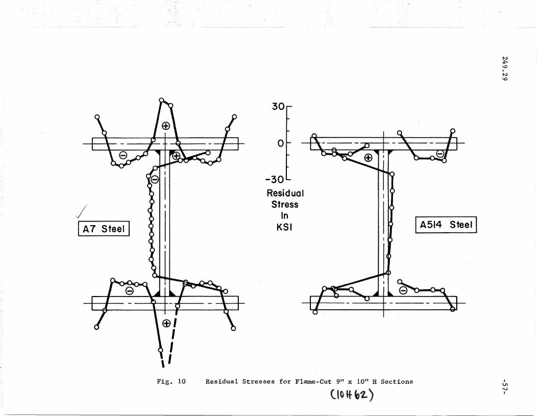
is shown in Fig. 10.
It was shown in Ref. 4 for rolled shapes that the effect of
yield strength on the residual stress distribution is not as great as
is the effect of geometry. This is shown for a 9 x 10 inch welded
shape in Fig. 10 where the residual stresses are compared for A36
and A5l4, steels respectively.
, Thick Plates and Heavy Shapes. (Filot Study)
Welded thick plates are used in buildings, bridges, and in
the hulls of ships and submarines. Unlike the "thin" plates considered
Little information is available on welded heavy shapes, yet
residual stress through the thickness.
ing gantries for rockets and space vehicles. In addition to the differ-
-10-
they are used extensively, particularly as structural members in the
lower stories of multi-story buildings, in major bridges, and in launch-
above, Itthick" plates generally will not have a uniform distribution of
249.29
{]Ience in thickness, heavy shapes differ from the lighter ones also in
that the ratio of area of weld to that of parent metal is smaller for
the heavy shapes. Thus, proportion~tely, there should be a smaller
heat input for heavy shapes than there is for lighter shapes, and so
heavy shapes would be expected to contain residual stresses of a smaller
magnitude.
The following p~eliminary results are those from a pilot
study on heavy shapes.
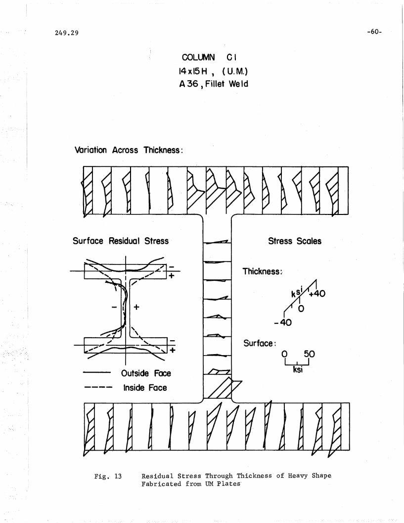
Surface residual stresses for a 14 x 15 inch H-shape of
A44l steel made up of TIM plates for a groove weld and a fillet weld
respectively, are shown in Figs. 11 and 12. The variation of resi-
dual stress through the thickness of the ~lange and web of Specimen
C-l is shown in Figo 13$ The magnitude of the residual stresses is
comparatively high, similar for both the fillet and groove welds, and
not less than in smaller shapes o . This is not in line with what was
expected· and will be discussed later. Similar information is presented
in Fig. 14 for a 14 x 15 inch H-shape of A44l steel made up of flame-
cut plates. The effect of flame-cutting is shown by the high tensile
residual stress at the flange tipso

249.29 -11-
It will be noted in comparing Figs. 11 and 12 that there are
slightly higher stresses (about 15% average) in Column C3 than in
Column Cl. The former, with groove welds, has a higher heat input,
and the difference, though small, is consistent with what would be
expected.
2.3 THEORETICAL STUDIES
Even though a considerable amount of experimental work is
involved in obtaining estimates of the magnitude and distribution of
residual stress, it is only through theoretical study that the whole
mechanism of the formation of residual stress can be understood. Also,
it is hoped that even more precise correlation can be established in
the future between theory and experiment.
There were two separate theoretical studies conducted during
the period of this summary report. The first study(7,11) considered
the whole topic of welded plates and heat input and presented a step
by-step method to compute both thermal and residual stresses for any
given welding condition o The step-by-step analysis represents the
complete thermal stress history of the plate. The second study(12)
presented a two-step method for determining residual stresses directly
and comparatively rapidly. The two-step method presents a great simpli-
fication in the computation of residual stresses; however, the thermal
stresses cannot be computed by this method 4
The thermal stress is defined as that stress existing at the
particular time interval in question after the onset of welding; the

-12-
residual stress is the thermal stress at a time interval of infinity -
that is, the residual stress is that existing when the plate or shape
has completely cooled.
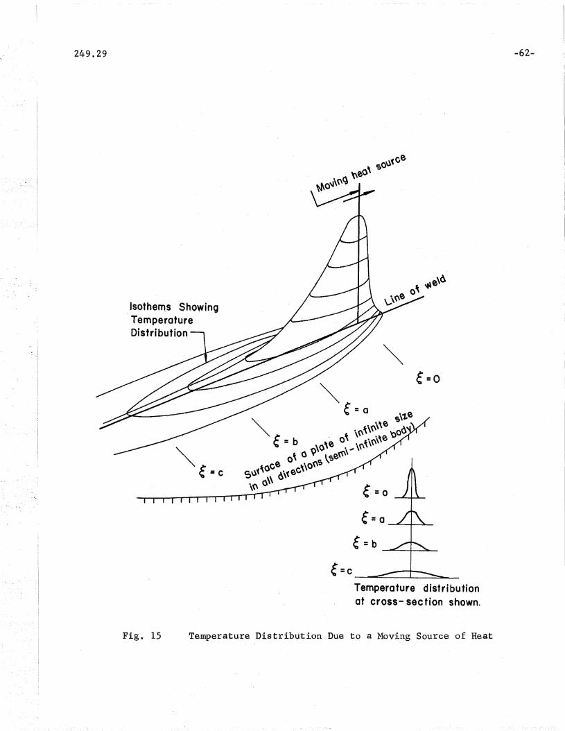
The temperature distribution in a plate heated by welding
depends upon the thickness and width of the plate, and speed of weld
ing, the position of the weld, the thermal properties of the weld, and
the heat input due to the weldingo Figure 15 shows, diagrammatically,
the temperature distribution due to a moving source of heat -- this
temperature distribution is called "quasi-stationary", since it is
constant with respect to the moving heat source 0 The computed tempera
ture distribution in an 8 x ~ inch center welded plate is shown in'
Fig. 16. The theoretical thermal and residual stress distributions
for this same plate and heat input are shown in Fig. 178 The effect
of multi-pass welds can be taken into consideration for the thermal
stress history, provided the time difference is known. (7,12)
The effect of heat input dominates all other effects con
sidered in-the computations -- such as geometry and thermal properties,
Figure 18 shows theoretically that the magnitude of the residual
stresses is a function of the magnitude of the heat input 0 The higher
heat input (broken line) creates higher compressive residual stresses
away from the weld; there is no direct relationship between heat in
put and residual stress as there is between heat input and temperature
distribution o Increased heat inputs do not increase the tensile resi-
dual stress at the weld because this stress is limited by the, yield
point of the weld metal o

-13- .
The computation for residual stresses developed in Ref. 7
included the effect of initial (cooling) residual stresses. Their
effect is particularly important in those areas away from the weld
where the material undergoes no plastic defor~tions.(ll)
The two-step method for the computation of residual stresses
represents a significant reduction in the amount of work required.
Since most structural engineering applications of residual stress are
not concerned 'with the thermal stress history, this represents a signi
ficant step. The two-step method(12) is based on the maximum tempera
ture envelope set up in the plate by welding e The residual temperature
strain which causes residual stress is the amount of cooling tempera
ture strain in excess of the portion which remains elastic during
heating o The elastic portion of the temperature strain at maximum
temperature is reversible and is fully recovered on complete cooling.
The residual stress set up depends on the elastic portion of the total
cooling temperature strain for each element when it reaches its maximum
temperature.
The residual stresses computed by the two-step method closely
approximate those computed by the much more laborious step~by-step
method.
The two-step method is of particular value when computing
the residual stresses in thi.ck plates, both the usual surface residual
stresses, and the residual stresses through the thickness o The use of
the step-by-step method would be so extremely long a~d tedious as to be
impractical for such plates. The two-step method and its application

2490,29 -14-
is still under development, and only a preliminary pilot investigation
has been conducted for the theoretical prediction of residual stresses
in thick plates and heavy shapeso
Figure 19 shows the computed residual stresses for the top
and bottom faces of a 6 x 1 inch A7 plate welded with a ~ inch center
V-weld. (12) The lack of correlation when compared to experimental
values is mainly due to not including the initial (cooling) residual
stresses in the computations 0
A similar comparison is shown in Figo 20 for an automatically
butt-welded 6 x I inch A36 plate -- the weld being deposited in four
passes in a double-V groove o The effect of pass sequence plays only a
limited role in the final residual stress magnitude, and thus only the
· 1 · d d b d· h · (12)maXlmum temperature 'enve ope lS nee e to e use In t e computatlono
Some preliminary considerations have been given to the pre-
diction of residual stresses in heavy shapes, including both the sequence
of fabrication and the use of flame-cut platese The analysis requires
a knowledge of the heat flow from the welding, that is, the heat input
proportions to the web and flangea Based on an analogy of the flow
of electric current, it was shown(l2) that for thin plates (plates
up to approximately 1 ino thickness) the heat is divided proportionately
to the relative plate thicknesses, and that for very thick plates the
heat is divided equally among the h'eat sinks (that is, the plates)
irrespective of plate thickness. For intermediate thickness (1 in~
to 2 ina approximately), a more complicated relationship exists for
the distribution of heat o

249.29 -15-
The preliminary theoretical study indicated that one reason
for the large magnitudes of residual stress measured in the heavy welded
shapes is due to the original residual stress distribution in the com-
ponent thick plates -- the actual joining process of welding contributes
only very small magnitudes of residual stress, in the order of 5 to 10
ksi. Further statements in this direction will depend on further studies
on residual stresses in thick plates. The only information on residual
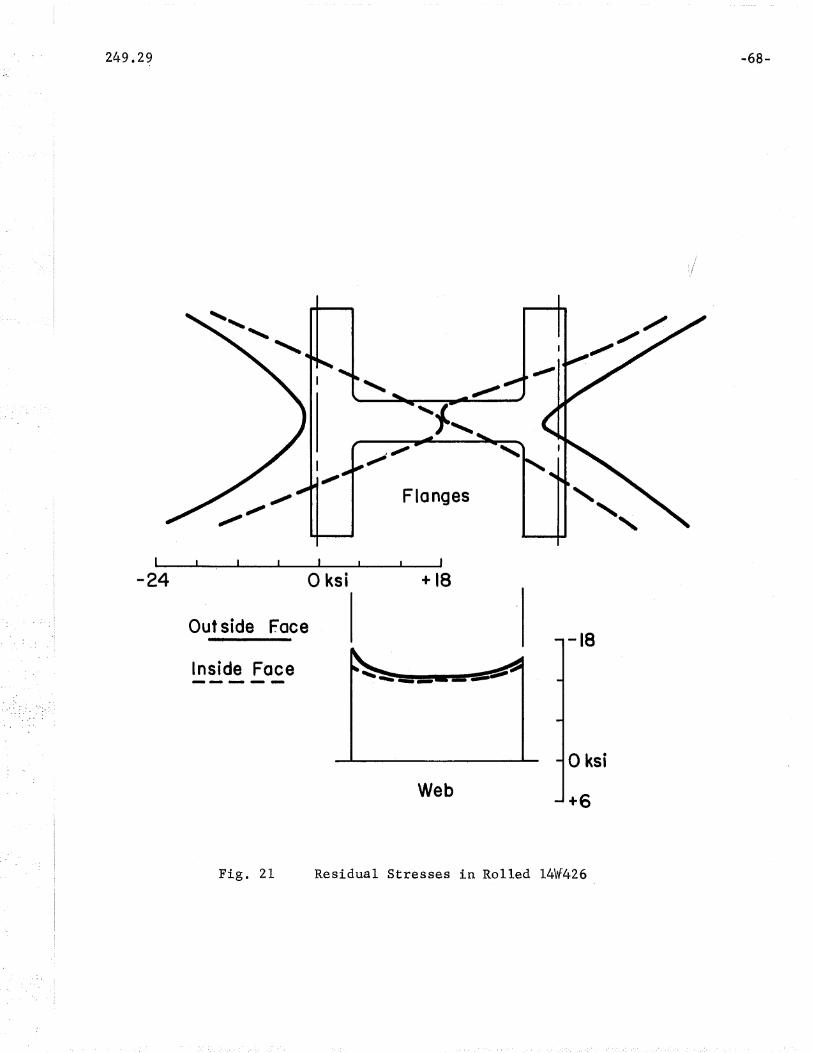
stresses for a heavy plate or shape is given in Fig. 21 where the resi-
dual stress distribution due to cooling from rolling is shown for a
14W426 shape. The high magnitudes of residual stress in this shape are
due entirely to the cooling process.
2.4 MECHANICAL PROPERTIES
Many of the mechanical properties of steel play an important
role in the formation of residual stresses and in the strength of com-
pression members. Those concerned affecting residual stresses have
been mentioned above. Probably one mechanical property more than any
other plays a dominant role in the overall picture, and that is the
yield value of steel.
The "yield point" and the "yield strength" have been defined
by ASTM(13) and are given in the Nomenclature below. The "yield stress
level ll is a useful term, and may be defined as "the average stress
during actual yielding in the plastic range~ It is the stress deter-
mined in a tension test corresponding to a strain of 0.005 in/in."
It remains fairly constant for structural steel provided the strain

249~29 -16-
rate remains constant.. The "yield stress" is a general term which en-
compasses all of these definitions for the yield value o
The relationship between these values for yield have been
discussed in Ref o 2, which also considered the influence of residual
stress on the stress-strain relationship for the complete cross section o
The influence of strain rate on the yield stress level was demonstrated Q
The "static yield stress lev'el", (J ,was defined as the yield stressY8
(14\level for a zero strain rate o ) It was shown to be a basic value
for the yield stress independent of machine, human, or strain rate
effects o The static yield stress level is of direct application to
the testing of structures and structural components and to research
into their strength.. It is important to note that most loads on
building structures are static o
In contrast to the static value, the "dynamic yield stress
level", 0 yd ' is the value of yield at the strain rate of testing,
that is, at a strain rate of other than zero o
During the study covered by this report, many routine tests
for the yield value were conducted, and the values obtained are re-
corded in the relevant reports referred to elsewhere in this paper o
One aspect of the yield value was studied in detail both for this
study and in collaboration with other studies; this was the effect of
strain rate on the yield stress of structural steels. (14)
Three structural steels were considered, A36, A441, and A5l4o
Relationships were determined: between the ratio (0 clio ) and the strainy ys
249 0 29 -17-
rate. These are not simple relationsh~ps and were determined through
regression analyses with confidence limits applied. Figure 22 shows
the variation of the dynamic yield stress ratio (a d /a ) with respecty ys
to the strain rate; the center line shows the mean relationship while
95% of all test results ,lie between the two outside lineso
The dynamic yield stress ratio increases rapidly at low
strain rates and very slowly at the higher strain rates included in this
study; in addition, as shown in Fig. 23, it decreases with increase in
. static yield stress level.
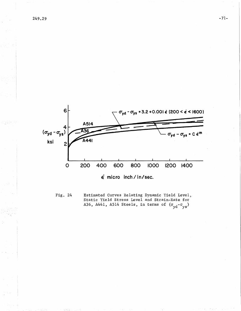
When the difference (Gyd
- cr ) for all three steels of theys
study is plotted with respect to the strain rate, Fig. 24, the mean
curves all lie in.a narrow band over a wide range of strain rates.
Thus, it is possible to use an average curve to define them:
cr d - 0 = 3 0 2 + -0.001 ~y ys
This expression may then be used to predict the static: yield stress
level of a specimen from ,a standard tensile coupon test; this equa-
tion is valid for the range of strain rate ,ZOO < ~ < 1600. Since the
strain rate does not greatly affect the difference (a d - cr ) fory ys
practical values of strain rate, the crosshead speed per inch of gage
length per second may be' used in place of strain rate in the equation.

3 0 COMPRESSION MEMBERS
The strength of a compression member depends to a great extent
on its slenderness ratioo Only very slender columns will buckle elasti
cally, and their buckling strength is defined by the Euler equation. (15)
(15 16)The reduced modulus concept ' had been regarded as the
correct buckling theory for columns in the inelastic range until 1947
when Shanley published a paper(17) giving the buckling load of a
centrally loaded column as the tangent modulus load o
Through the efforts of the Committee on Research of the Column
Research Council (18) a decade and a half ago, it was shown that the key
to the application of the tangent modulus concept to the steel column
lay in the inclusion of the effect of residual stresses which existed
in the cross section of the column even before the application of
external load o
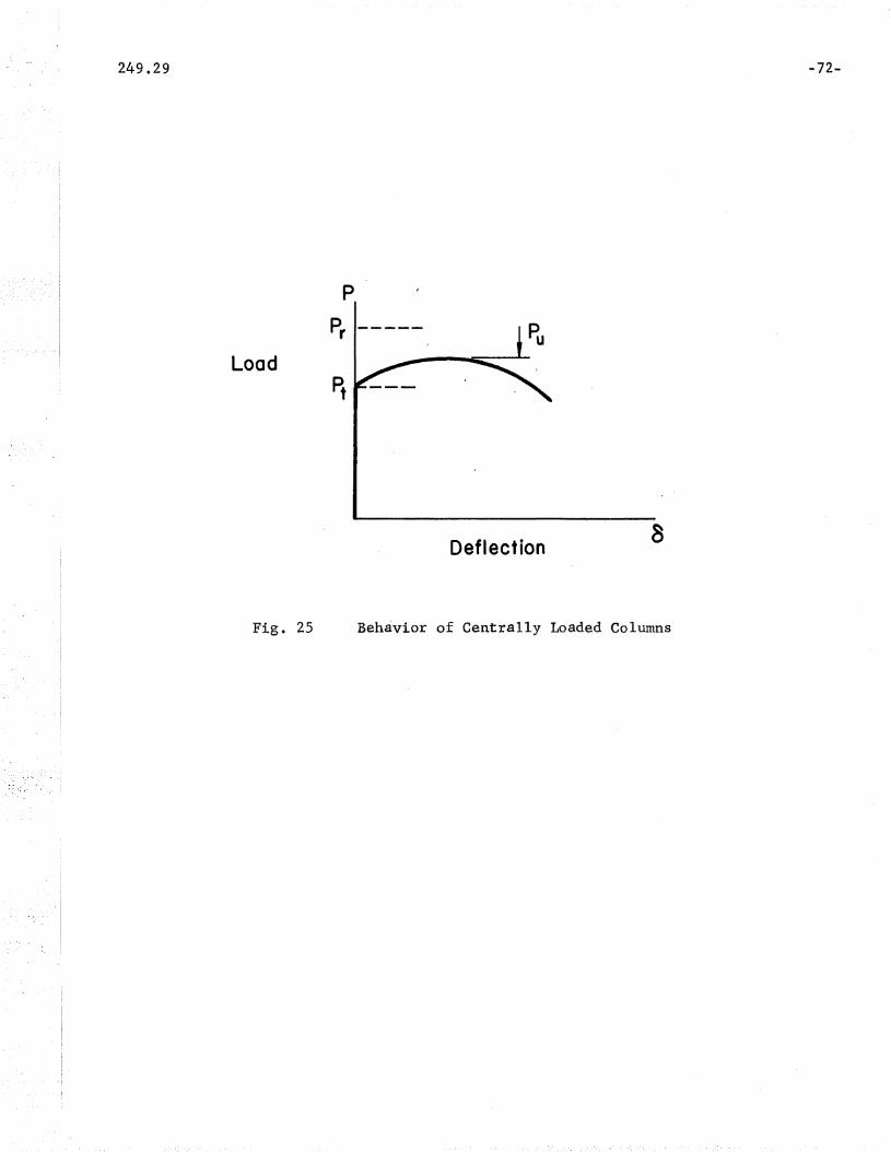
The tangent modulus load is the lower bound for column
strength; it is the load at which an initially straight column.will
start to bend o The upper bound is the reduced modulus load since it
is the maximum load a column will sustain if it is temporarily
supported up to that load o The ultimate load of a column will lie
between these two limits o Generally, test results will tend to approxi-
mate the tangent modulus load o Further, since it is a lower bound, the
tangent modulus load has been used as the basis for a column strength
formula. (19) The behavior of an ideal centrally loaded column is typi-
-18-

249.29
fied by the load deflection curve in Fig. 25.
-19-
For a pinned-end column, the "buckling load" is defined as
the bifurcation load, that is, the load at which the theoretically
straight column is indifferent to assuming a deflected position. The
column will deflect and will then continue to deflect laterally and to
take further load. (15,17) The "ultimate load" is the maximum load a
column can carry; it is reached gradually unlike the buckling load which
is an instantaneous phenomenon.
To take into account the transition in the column curve from
the Euler ,curve to the yLeld value, it was the practice in the past to
develop complicated correction factors using estimated eccentricities
or initial deflections, such as, for instance,:were applied to the
secant formula. It has beenshown(2) that, for the hypothetical case
of straight centrally loaded pinned-end columns, the transition· curve
is due entirely to the presence of residual stresses in the cross section.
3. 1 RESIDUAL STRESSES AND COLUMN BUCKLING
For column cross sections containing residual stresses the
tangent modulus and reduced modulus theories for column buckling de
fine buckling loads differing from those for the same column free of
residual stresses. (20) A column cross section containing residual
stresses will have certain fibers yield before others when the column
is loaded. Compressive residual stresses exist in these fibers even
before the load is applied. The material of the cross section is no
~20-
longer homogeneous and the general equations for tangent modulus and
reduced modulus no longer apply. (4) However, a comparatively simple
solution for column buckling strength may be obtained with the tangent
modulus concept when it is assumed that every fiber in the cross-section
has an idealized elastic-plastic stress-strain relationship, which does,
in fact, exist for most structural steels. (15) Thus, it was shown(2l)
that the buckling strength is a function of the moment of inertia of
the elastic part of the cross section at that load o
Rolled Columns
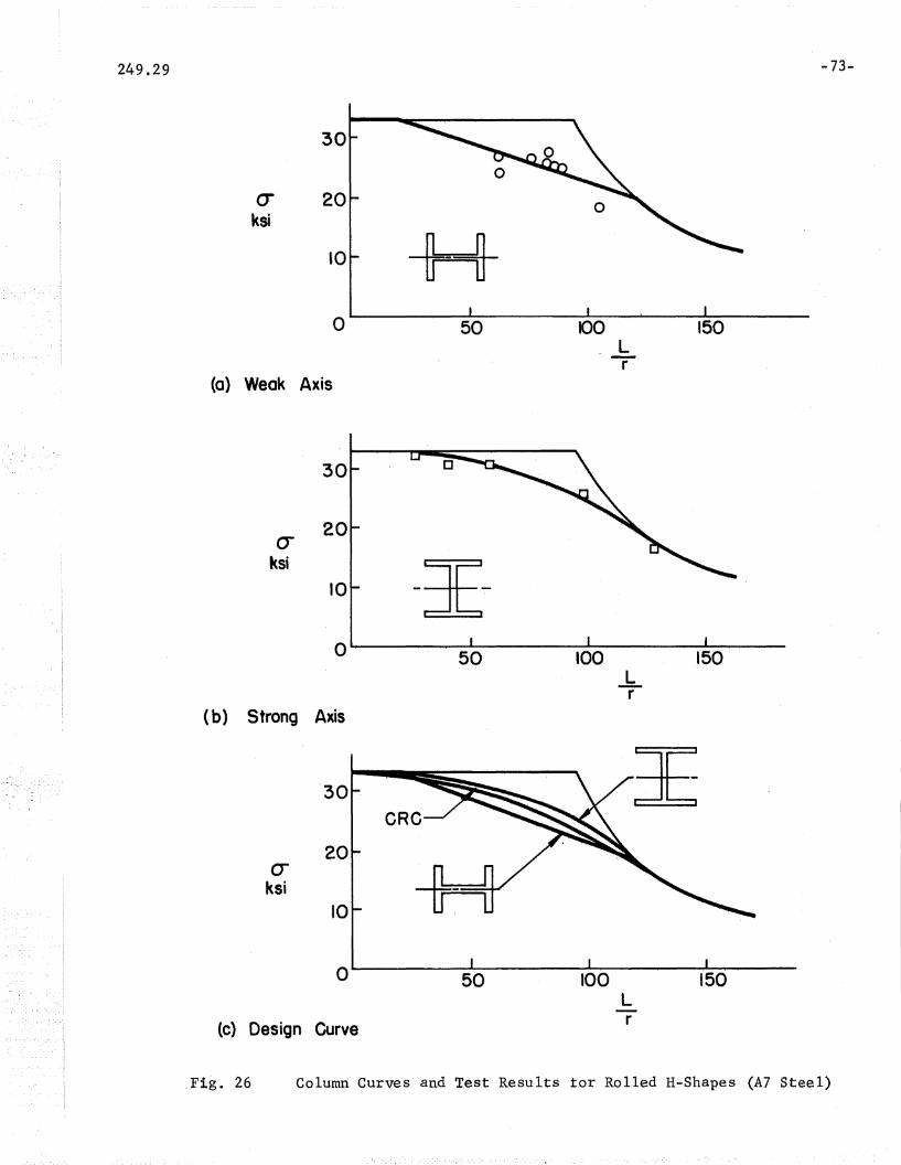
When the column curves for rolled H-shapes of structural
carbon steel are prepared, it will be seen that the straight-line and
parabolic curves give satisfactory predictions for column strength in
the weak and strong axes respectively. (2) The ultimate loads carried
by such columns do not exceed the tangent modulus load enough to
warrant other prediction me~hods.
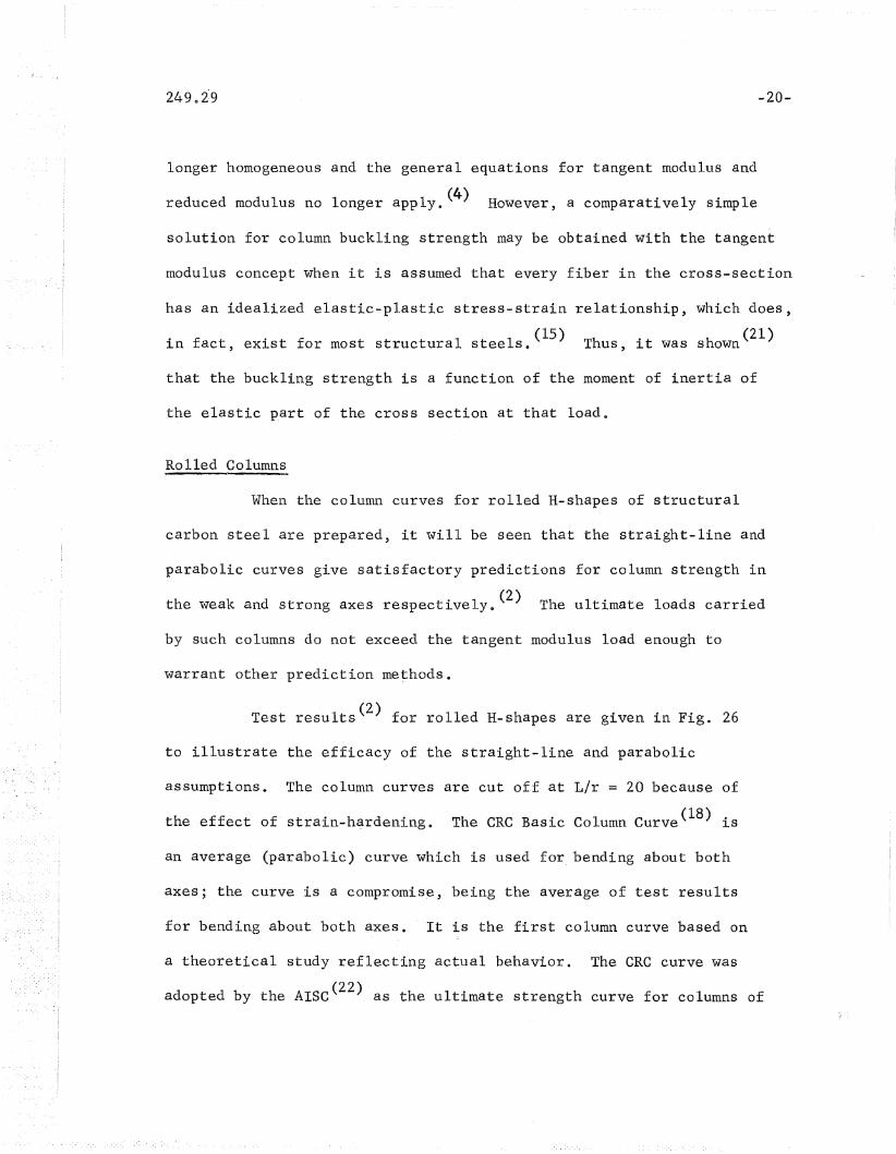
Test results(2) for rolled H-shapes are given in Fig. 26
to illustrate the efficacy of the straight-line and parabolic
assumptions. The column curves are cut off at L/r = 20 because of
the effect of strain-hardening. The CRC Basic Column Curve(18) is
an average (parabolic) curve which is used for bending about both
axes; the curve is a compromise, being the average of test results
for bending about both axes. It is the first column curve based on
a theoretical study reflecting actual behaVior. The eRC curve was
adopted by the AISC(22) as the ultimate strength curve for columns of

249.29
structural carbon and high strength steels (yield points from 33 ksi
-21-
to 50 ksi).
It was shown in Ref. 4 for rolled shapes and in Fig. 10 for
welded shapes that the magnitude and di~tribution of residual stresses
depend mainly on the geom~try, and very little on the yield point of
the material. Hence, it may be concluded that, as the yield strength
increases, the effect of residual stress on column strength decreases.
Except for the very s lender co lumns, higher- c'olumn"" stren1gths· 'are'- ob,taiited
most simply by using steel with a higher yield point. Hence, the use
of high strength steel gives higher column strengths by virtue both of
the higher yield point and of the relatively decreased effect of resi-
(23 24)dual stresses. ' Figure 27 presents some experimental results on
weak axis column tests of the same cross-sectional shape for three
different steels; it is seen that the influence of residual stresses
on the strength of the columns of higher yield strength is not as pro-
nounced as it is on the columns of lower yield strength. (The informa-
tion in Fig. 27 has been non-dimensionalized to facilitate comparisons,)
Currently, no allowance for this effect is made in column formulas.
3~2 WELDED COLUMNS
The strength of centrally loaded welded columns can be pre-
dicted by the same techniques as for rolled shapes with cooling resi
dual stresses. However, it has been shown(11,25,26) that the use of
the ta,n-gent modulus concept gives too conservative a result and there-
fore is not realistic for the prediction of the strength of welded
249.29 -22-
columns -- an ultimate strength analysis is necessary. (25) Further,
for welded columns, there is a greater effect due to out-of-straight-
(11 27)ness than for rolled shapes; , the out-af-straightness together
with the high magnitudes of compressive residual stress produce the
lower strengths.
Hence, the study of the strength of centrally loaded welded
columns differs essentially from that of centrally loaded rolled col-
umns -- welded columns need an ultimate strength study whereas the
tangent modulus buckling load presents a realistic figure for rolled
columns.
For centrally loaded columns, the ultimate strength is a
load (in excess of the tangent modulus load) for the column in the
deflected position, and hence is a post buckling problem for the
column in the inelastic range. It is difficult to obtain a per-
fectly general solution for the ultimate load except for very simple
column shapes which do not contain residual stresses and where the
stress-strain relationship of th~ material may be expressed in simple
Columns which are eccentrically loaded either due to ini-
tial imperfections, eccentricity of application of load, initial de-
flection or curvature, or non-symmetry of residual stresses, show a
d d f 1 t th (11,28,.29)pronounce re uction 0 co umn s reng ~ Eccentrically
loaded columns may be analyzed theoretically in exactly the same
manner and with the same approximations as tho~e used to determine the
ultimate strength of centrally loaded columns; in this case, however,

-23-
account must be taken of the fact that the eccentrically loaded column
will start deflecting immediately upon application of load.
The theoretical analyses for ultimate strength are based on
a number of simplifying assumptions to take into account such variables
as geometric shape, residual stresses, stress-strain relationship,
deflected shape of column, and have been described and summarized in
Ref o 4, and are given in detail in Refs o 11, 25, 26, 30 throu'gh.
35'.
Theoretical and experimental test results for the strength of
welded columns are given below o
The strength of welded built-up columns of A7 steel is shown
in Figs. 28 and 29 for H- and box-columns of small size, (6" x 6" to
10" x 10"). (27) The theoretical ultimate loads are compared with the
experimental values in Fig~ 290
The same experimental results for A7 columns are shown' in
Figo 30, in comparison with the eRe curve adopted for design by the
AISC. The reason for the somewhat lower strengths is twofold: the
effect of residual stresses due to welding, ~nd the effect of initial
out-of-straightness.
The column with an initial out-of-straightness deflects
from the beginning of application of load. The out-ai-straightness
creates early yielding in the region of high compressive residual
stress -- this increases the column deflection, which in turn creates
further yielding. The process continues until the maximum load is

-24-
reached; the process is more accelerated for the welded column than
for the rolled column -- for the welded column, the maximum load is
comparatively small and reached at a comparatively large deflectionD
This is illustrated for rolled and welded column test results in
F ~ 21D(1,27)_l.g 0
The maximum effect of out-af-straightness occurs for the
longer columns, (L/r from 60 to 120) and this effect is discussed
below. For shorter columns, (L/r from 30 to 60.) the box shape tends
to be stronger than the H-shape bent about the weak axis, 'since box-
shapes retain the corners in the elastic condition throughout the life
of the columns due to the favorable tensile residual stresses there as
a result of the weld. (For the same reason, box shapes are able to
sustain the maximum load for much larger deflections than the H-shapes. (11»
H-shapes, with the compressive residual stresses at the flange tips;
lose a major part of their rigidity very early under load, since the
,flange tips yield firsto
A lffavorab1e" distribution of residual stress is one that
leads to improved column strengtho A favorable distribution has tensile
residual stresses furthest from the axis of bending. Such a benefit may
be seen from Fig. 32 which presents experimental results o Rolled box
and H-shapes are compared with their welded counterparts. In every case,
the rolled column displays a somewhat superior strength. Figure 32 shows
that a reversal of the normal pattern of residual stress in the flange
tips of an H-shape improves column strength markedly -- compare the
rolled 8~31 shape before and after reinforcing by welding cover p1ates(lO)

-25-
(Fig. 32c), and compare the Japanese welded H-shape before and after
h d ~. f b d f 1d 1 h f1 · F· 32 (36)t e epos1t1on 0 a ea 0 we a ong t e ange t1pS, ~go c.
The great improvement in the strength of a welded column after removal
of residual stress by annealing is also shown for the Japanese shape(36)
and for the 8W3l rolled shape, (1) Fig. 32d.
Reversal of the residual stress in the flange due to welding
of the flange tips or due to the use of flame-cut plates leads to higher
column strengths for H-shapes. However, the strength of welded box-
columns made from either machined or flame-cut plates is the same, since
the process of welding does not change the favorable residual stress
distribution in the flame-cut plate~ This is discussed further below.
303 FACTORS IN COLUMN STRENGTH
Aside from the effect of residual stress, a number of other
factors should be considered in any general study of columns, both
rolled and welded o These factors may play an important part i~ design.
Those to be considered here are the shape of the cross section, higher
yield strengths,·out-of-straightness, and cold-straightening.
No particular shape can be regarded as being best for column
use o Box-shapes, however, are somewhat stronger than corresponding
H-shapes because of their favorable residual stress distribution; a
cost-strength study would need to be made for any final decisions.
For the low slenderness ratios (L/r up to about 50) when out of straight-
ness is not as important a factor as for high slender.n~ss ratios,

-26-
columns with a favorable residual stress distribution will be stronger,
than columns with an unfavorable distribution o Whether the residual
stress is due to welding or to cooling after rolling, if the material
furthest from the axis of bending is in a state of residual compression,
then this material will yield first under load, leading to column failure
at a lower load than would otherwise be expected.
Except for slender columns, higher column strengths are ob-
tained most simply by using steel of higher yield strengtho This was
considered for rolled shapes above, (Fig. 27), and the same general
comments apply for welded shapes, as may be seen in Figs. 33 and 340
Out-af-straightness is a significant factor involved in the
strength of columns. Out-af-straightness is used here to refer to all
deviations which result in an eccentrically loaded column: initial
curvature, eccentric application of load, and unsymmetrical residual
stress distribution o In general, the maximum out~of-straightness
allowed by specifications for columns is of such a magnitude that the
corresponding weld~d-column strength-will lie on the lower boundary of
the test results shown in Figo 300 The expected maximum out-of-
straightness (for example, ~ in o in a 20 ft. column, AISC Specifica
tions(22) will reduce the column strength about 25 percent below that
indicated by the eRC curve in the medium slenderness ratios (L/r about
60- to 120)0 The effect. of out-of-straightness on shorter columns is
not as great.
The usual structural columns, rolled or welded, will be cold-
straightened to the specified tolerances o For rolled shapes, the pro-

-27-
cess of cold-straightening induces residual stresses which are of a
similar magnitude, although different distribution, to the cooling
residual stresses. (37) This means that findings based on rolled mem
bers with cooling residual stress patterns will be conservative when
applied to straight rolled members whose cooling residual stress patterns
have been modified by cold bendingo At present, there are no test data
on the effect of cold-straightening on welded columns. The effect of
cold-straightening depends on the manner by which it is carried out,
whether by "gagging" or by ftrotorizing"Q "Gagging" concentrates the
straightening at a few sections, leaving most of the column with its
initial state of residual stress o "Rotorizing" is a continuous straight-
ening process and changes the residual stress pattern completelyo In any
case, column strength based on cooling or welded residual stresses will
normally be considered, as there is no assurance that the column will
be cold-straightened so that these residual stresses will be changed
to a more favorable distribution o
304 REINFORCED COLUMNS AND HYBRID COLUMNS
Hybrid construction is quite common today because of the
multitude of steels available. Thus, structures can be designed eco
nomically by combining these different steels in hybrid construction
the higher grades of steel can be placed where the most strength is
needed 0
Either the structure itself may be hybrid, or else a struc-
tural member may be hybrid o For instance, a hybrid structure such as

249.29 -28-
a multi-story frame would use high-strength steel columns for the lower
stories, and mild-steel columns for the upper stories. On the other
hand, the hybrid member uses different grades of steel within the
member itself -- a column section would use the high strength material
in the flanges. Design information has been available for hybrid
beams and girders. (38).
The results of a theoretical and experimental study of ,the
strength of hybrid columns(35) have shown that, except for very short
columns, the behavior of the hybrid member is essentially identical with
that of the homogeneous member when it is assumed that the shape is
homogeneous high-strength steel throughout 0 Two principal types of
shape were investigated, one with A5l4 steel flanges, flame-cut, and
either A36 or A44l steel web, and the other with either A44l liM or A44l
flame-cut steel flanges, and A36 steel web. The residual stress distri-
bution for these hybrid shapes are the same as those of homogeneous
shapes. (35) Thus, the test results shown in Fig. 35 may be expected
from a knowledge of the strength of similar homogeneous columns.
Figure 35 shows the computed tangent modulus curves for each test
column, together with experimental results.
In the lower stories of multi-story buildings where the
slenderness ratio of columns is low, columns of A5l4 steel might be
considered. In the stories immediately above these, hybrid columns
might be more economical because the lower-strength steel in. the web
can be overstressed without adverse effect. (35) This latter statement
is important and reflects the strength of a yielded web when the

249.29 -29-
proper bit ratios have been chosen; this is discussed below, Section 3.6.
A variation of the hybrid column is the column which is re-
inforced, often under load. A column is reinforced usually by welding
cover plates to the flanges often the structure is· in use and so
the reinforcement is carried out under load. One series of such
columns of A7 steel(lO) was welded under loads as high as 75% of the
yield stress without ca~singany buckling or other changes. This is
because the influence of welding was .c'orifined to a very small area in
the vicinity of the weld. The mechanical properties in the major por
tion of the section are not affected' enough to reduce the strength of
the section. This holds true only when the weld is deposited along
the length of the column -- if the weld is deposited transversely as
with a splice, then the area affected by the weld becomes very large
and critical, and the above statements no longer hold true.
Reinforcing improves the strength of columns, both because
of the additional material and also because of the creation of a more
favorable residual stress distribution. This is demonstrated above
in Fig. 9; the welding changed the compressive residual stresses to
t'ensi Ie residual stresses. This is reflected in Fig. 36 - - the differ
ences between the theoretical tangent modulus predictions for unre
inforced and reinforced columns reflects the difference in residual
stresses. The limited experimental results available bear this out.
Little difference was observed between the strength of columns welded
under load or under no load e
249.29
Reinforcement may also be accomplished merely by laying a
bead of weld along the flange tips. The additional strength is
achieved through the reversal of the residual stress there -- this
additional strength can be quite substantial, as shown for the
Japanese results in Fig. 32.
3.5 HEAVY COLUMNS AND FLAME-CUT PLATES
-30-
Although the results presented thus far show that some welded
columns are not as strong as rolled columns, it should not be concluded
that this is necessarily true for all welded columns. Those results
were obtained from studies of welded columns built up of universal mill
plates. They were H-shapes whose maximum size was 9" x 10" with 3/4"
plates. lhese are relatively small members.
An impor,tant observation already made is the "favorable"
residual stress distribution in flame-cut plates. Under some circum
stances it has also been noted that the high tensile stresses at the
edges of such plates are not decreased substantially when they are
welded into shapes (see Fig. 10). Thus the shape retains the favor
able pattern which has tensile stresses at the flange tips of an
H-shape, and consequently one would expect it to be a higher strength
than would otherwise be found in a welded column.
In addition to this, columns that are welded together from
thick plates may be joined with welds that are considerably smaller
with respect to total shape area than is the case with thinner plates.
Thus, proportionately, there is smaller heat input for heavy shapes,

-31-
and so they would be expected to contain compressive residual stresses
of smaller magnitude.
On the basis of these trends, therefore, preliminary pilot
studies were undertaken into welded columns with flame-cut plates and
into heavy columns welded from thick plates.
A comparison of the preliminary test results is shown in
Fig. 37 for 6" x 7" and 9" x 10" welded H-shapes, both flame-cut plates
and universal mill plates; the favorable residual stress distribution
of the flame-cut plates does result in an increase in column strength.
This pilot study indicates that welded shapes fabricated from flame-cut
plates are stronger than their liM counterparts and may even approach a
strength comparable to that of rolled Wsections.
The residual stress distributions in the heavy welded shape
of the test program is shown above in Figs. 11, 12, and 13; based on
preliminary conclusions from these tests, it would appear that the
comparatively large magnitudes of residual stress may be due more to
cooling after rolling .than due to welding. If this is true, then a
reduction of weld size will not lead to improved column strength.
This must be explored further.
No column tests have yet been conducted on heavy welded
shapes; preliminary theoretical strength predictions for one heavy
shape are available. (12) This is shown in Fig. 38 for a 14" x 15"
H-shape, A36 steel, for a fillet weld~ There is a strength in
excess of that of a small 9" x 10" welded column. When the varia-

249.29 -32-
tion of residual stress is considered for the strength of column C4,
the tangent modulus load is quite high in the lower slenderness ratios,
but not for the higher slenderness ratios. That is, in the range of
practical values of column slenderness ratios found in buildings,
30 to 60, the strength of a welded heavy shape compares favorably with
the strength of rolled W shapes~ For higher strength steels, the in-
fluence of residual stress decreases.
It is important, therefore, to complete a program which will
specifically delineate the influence of geometry and edge preparation
in order that consistent design recommendations may be prepared.
3.6 WIDTH-THICKNESS ,RATIOS AND PLATE BUCKLING
Studies of plate buckling as influenced by residual stress
have been underway simultaneously with other phases of the overall in-
vestigation of residual stresses and the strength of compression
b(14',39,40:,41,42)
mem ers. It was felt at the start of the research pro-
gram that lower width-thickness ratios may need to be specified for
the component plates of welded shapes. The studies have been both
theoretical and experimental. Generally, the behavior of plates of
high strength steel have been of more interest than that of, structural
carbon steel, since the use of high strength steel leads to thinner
plates.
Reasonable correlation was obtained between test results
and predictions for plates containing residual stresses of welding

~ \(3f+ 39 40 ~ 1 L~2 )or cool~ng types (! J' ~ ./ ) 'Ib.:Ls:Ls shown in F:Lgs <) 39- and (~·O ~ for
have been obtained for a wide '\7ariety of -residual stress d:Lstr:i.bllt:I,ons,
both, 'welding and (',ouling, for I',lates ·u.nd~~~c 'V8:r:':LOU.8 edge c(;ndit.ion,8~
Trle edge eOl).ditions \i\i'err2~ cnosE~n to 1>8semble \ttfe.b plates in rl,-shapes as
well as componeD.t plates for hO.K shapes I'
The theoretical studie.:s cons-id.ered elastic:') 81ast:i.c"~'T,lastic;:)
and pIa s tic: b l1c.lc.l i ng ., :['0reIas tic b u c~k, 1. ing () f a p la, t E; "('11/ i t~1 re 8 i d, 1.1a 1
evaluated frorn th,~. l'esidual str,BSS .distribut.ion; ~figso 39 ar!.d 4·00 11112:
posB:Lbil:Lty th.ut a plate with residual. stresses may l)"u.ck.le t<\r':Ltl"iou,t any
extern.B.l load is ShO~Ntl i.n Figs 0 39 arid, 40 1I This fact: 'f.;~'K:'Pla:LnB vd:-()l ·8.
plate can distort due only to welding. Tests showed, (Figs~ 39 and 40)
that although considerable post buckling strength occurred fo~ elastic
buckling of plates, this was not the Ca8E~ :tOT '81a.st.i.e.~p18A~ti('. buc"klin.go
!~8.t :Los a:t:'e t;B.sed
on the aS8'U.ITJ.ption t'hat no plat,e buc.kling oecurs u,nt::1.1 th,'2; yie~ld load
of the secti.on is rea(,:hied and that the plate bu.ek.ling Ctlr'\Tr.:~ inte-rse.cts
tile yield line (line AI-) i.n Figo 39) at ?O!~ of thE: bit ratio for t118
elastic plate buck.ling CU'!.'lj;'e free of J:'f.:;sidlJa,l st.ress (poirlt C in
Fi.g. 39) ~ This assu~mption is sOInevJhat (~onser'va:tive for rolled A7
" (42'~SDlapes a' )J
, Nevert]].eless ~ it is a good represeD.ta.t:Lve aS8ulnption" BaB~:~d on tllis

point on the non-dimensionalized curve, (point C in Fig~ 39) the
specification gives the bit ratio for steels of different yield
strengths, non-dimensionalized by a factor of 1/0. Thps, if they
-34-
specification is conservative for A7 steel, it is certainly conserva-
tive for A514 steel, since residual stresses playa much smaller role
with the higher strength steels. (34) Although the pilot tests indi-
cated that the AISC bit ratios may be slightly optimistic, there seems
to be no reason for not using them for A514 steel o Thus, the AISC
width-thickness ratios could be used for steels of yield strengths up
to that of A5l4, for both welded and rolled shapes, Table 2 e
3.7 DESIGN IMPLICATIONSi
If all welded columns were not as strong as rolled columns
then there would be no way of avoiding the application of some kind
of reduction f~ctor to the column formula for welded members. In all
likelihood this factor would be variable with respect to the slender-
ness ratioo
The fact that some classes of welded columns are stronger
than others suggests that correction factors would be needed only
for certain classes of welded columns in order to have a consistent
factor of safetY9
Another approach would be to decide what minimum factor of
safety is needed and to select one formula to apply to all columns,
selecting ~s the base the average strength of that class of columns

249.29 -35-
that consistently give the minimum strength. Although this procedure
would be simple, it would be wasteful of material, since many classes
of columns would have strengths in excess of the minimuffi0
A more rational approach -- providing for more economical
structures with uniform safety -- is to delineate those conditions in
which a column would fall into one category or another. Such categories
would be established to take into account the demonstrative differences
due to: method of fabrication, yield point of the material, edge pre
paration, geometrical configurations, and so on o Then through appro
priate correction factors or formulas, consistent designs could be
achieved. These formulas or factors would be minimal in number two,
or at most three. Of course, the designer always has the option of
using the most conservative factor if he wishes to do so.
The most critical need, however, is to complete what has been
started to determine the influence of edge preparation (flame-cut
edges), the influence of thickness, and other geometrical and welding
effects. Upon these results will depend the specific design recommenda
tions.

4. SUMMARY
It is the purpose of this paper to summarize the experimental
and theoretical studies conducted into the strength of welded columns
of structural carbon steel, These studies also included investigations
of re~idual stresses and mechanical properties. The column sizes of
the investigation are limited to 10" x 10"; some preliminary results
are presented for one heavy shape.
Column Strength
1. The presence of residual stress is the reason for the transi-
tion curve in the column curve for initially straight axially loaded
columns, Residual stresses reduce the buckling strength because of the
early localized yielding that occurs at certain portions of the cross
section. (Section 1, Fig. 1.)
2. The strength of rolled columns may be expressed simply in
terms of the tangent modulus. (Section 1.)
in shape from those in rolled H-shapes, and considerably larger in
Residual Stress
3. The residual stress distribution ~n welded plates differs
from the rolled counterparts in that the shape of the pattern tends to
be more unfavorable with respect to column behavior. (Figure.,,~.)
4. Welded H-shapes have residual stress distributions different
-36-

249.29 -37~
magnitude. Compressive and tensile residual stresses are distributed
over approximately the same areas of the cross section. (Figure~6~)
5. Box shapes, fabricated from four plates, have high tensile
residual stresses at the corner welds and compressive residual stresses
elsewhere, (Fig. 6.)
6. The residual str~ss oistribution in a welded shape is similar
in shape and to within about 15% in magnitude to the separate residual
stress dis~ributions of the component welded plates. (Section 2.2.)
7. The residual stress distributions in welded plates and shapes
may be estimated from tables of stress values prepared from this study.
(Table 1, Fig. 8.)
8. The compressive residual stresses in the flange tips of
H-shapes may be reversed to tension by reinforcement, either by the
welding of cover plates to the flanges, or by the placing of a line
of weld along the flange tips. (Figure 9.)
9. Flame-cutting, being a source of heat, leaves residual
stresses of tension at the flame-cut edge after cooling~ (Section
2 .2, Fig., ~O.)
10. Welded H-shapes fabricated from flame-cut plates will retain
tensile residual stresses at the flame-cut edge. (Figure 10.)
l~. The magnitude of both compressive and tensile residual
stresses measured in a 14" x 15" ~elded heavy H-shape was comparatively
high, and was not less than that measured in smaller welded shapes.

249.29 -38-
It.,is suggested that the large magnitudes of residual stress in heavy
welded shapes may be due to the original cooling residual stresses in
the thick rolled component plates. (Section 203, Figs. 11 and 12.)
12. The effect of heat input dominates all other effects in the
creation of residual stresses. (Section 2.30)
13. It is possible to determine theoretically the residual
stresses in welded plates and in certain welded shapes. Two methods
were prepared in this study: the step-by-step method which determines
also the thermal stresses, and the two-step method which· presents a
quick and accurate method of computation. (Section 2.3, Figs. 17 and
19.)
Mechanical Properties
14. It was possible to develop a simple relationship between the
static yield stress of steel and the strain rate of testing. (Section
2.4, Figs. 23 and 240)
15. Yield stress has a small but negligible effect on the magni
tude of residual stress; hence the influence of residual- stress on the
strength of columns of high strength steel is not as pronounced as for
columns of structural carbon steel. (Section 3.1, Figs. 27 and 33.)
16. Welding changes mechanical properties only in the vicinity
of the weld,. The yield stress of the weld metal is about 50% higher
than that of the parent material for structural carbon steel. (Sec
tion 2.2.) (On the other hand, weld metal in A5l4 steel will have a
lower yield stress than the parent material when a lower strength e1ec-

249.29
trode is used.)
-39-
Welded Columns
17. Welded columns contain residual stresses of a larger magnitude
than do comparable ro~led columns ~- this implies that column strength
characteristics are different for such welded columns from those for
roll~d columns. (Section 3.2.)
18. Welded H-shaped columns fabricated from UM plate tend to have
lower strengths than corresPQnding rolled columns. This is due to two
effects: a) the greater compressive residual stress, and b) the ini
tial out-of~straightnesswhich has a greater effect for larger magni
tUQes of compressive residual stress. (Section 3.2, Fig. 31.)
19. Welded box columns tend to be stronger than welded H-columns
bent about the weak axis because of a more favorable residual stress
distribution. (Section 3~2, Fig. 30.)
20. Tensile residual stresses at the flange tips are favorable
for the strength of H-shaped columns, (Fig. 32.)
21. Maximu~ column strength in H-shapes is obtained from "favor-
able" residual stress distributions ~- such as due to the use of flame
cut plates. Other favorable distributions are those due to reinforcing,
either by welding cover plates or else by laying a bead of weld down
the flange tips, (Figs. 32 and 37.)
22'. Annealing will remove most of the residual stresses, and
this improves column strengtij~ (Fig.,32.)
249.29
23.
-40-
The strength of welded columns may be affected by the welding
process, since the welding process has a direct effect on the formation
of resioual stress. !n theory, welded columns of higher strength could
be fabricated if welding techniques could be developed such that lower
heat inputs are generated resul~ing in lQwer magnitudes of residual
str~ss. (Section 2~_3.)
24. Hybrid columns, with low~strength web and high~strength
flanges, may be designed on the assumption that the shape is homo
geneous high-strength steel throughout, except for very short columns,
because the lower-strength web can be overstressed without adverse
effect. (SectiQn 3'.4.)
25. The flame~cutting of structural plates used in the fabrica-
tion of columns by welding improves the strength of H-shaped col~mns
in comparison to rolled columns.- Preliminary studies on two small
shapes have indicated that the strength of welded shapes furnished
from flame-cut plates may approach that of comparable rolled shapes,
for structural carbon steel. (Section 3.5, Fig. 37.)
26. Preliminary theoretical studies, taking into account the
variation of residual stress throughout the thickness of the flanges,
have ,indicated that heavy welded columns may have strengths greater
than small welded columns for slenderness ratios less than about 50.
(Section 3.5, Fig. 38.)
27. In summary, the present status of studies of the strength of
welded columns is that there are certain categories o~ welded columns

249.29 -41-
whose strength does not match that of their rolled counterparts. On
the other hand the~e ~s evidence that other classes of welded columns
are stronger th~n the minimum observe~ up to the present time. The
present crit~cal need is to carry out st~dies which will enable one
to cat~gorize the differences and to prepare appropf~ate design re
commendations.

5. ACKNOWLEDGEMENTS
This paper presents a summary of the results of an experi
mental and theoretical study int~ the strength of welded columns.
The investigation was conducted at Fritz Engineering Labora
tory, Department of Civil Engineering, Lehigh University, Bethlehem,
Pennsylvania e The Pennsylvania Department of Highways, Uo So Depart
ment of Commerce - Bureau of Public Roads, sponsored the major part
of this studYe Associate studies, referred to in this paper, were
sponsored by the American Institute of Steel Construction, the
United States Steel Corporation, and the Engineering Foundation
through the Column Research Council. Column Research Council Task
Group 1 under the chairmanship of John Ao Gilligan provided valuable
guidance.
Special thanks are due to Lynn So Beedle, Director of Fritz
Engineering Laboratory and Acting Head, Department of Civil Engineer
ing, for his helpful criticism and advice in the preparation of this
paper, and throughout the course of the investigation. Fiorello R~
Estuar reviewed the paper and made a number of excellent suggestions
which were incorporated 0 William Co Cranston assisted in the prepara
tion of the figures. Appreciation is due also to the author's col
leagues who assisted in various parts of the study and to whose work
reference is made throughout the paper.
-42-

249.29
6. NOMENCLATURE
b width of cross section of shape; width of plate
bit width-to-thickness ratio in plate
c distance from neutral axis to extreme fiber
e eccentricity of load; out-af-straightness of column
elb eccentricity ratio in column
E modulus of elasticity
Et
tangent modulus
I moment of inertia
L column length between pin ends
L/r slenderness ratio
P load; subscript y refers to load at yield
r radius of gyration
t thickness of plate
€ strain
strain rate = cle./dt
deflection of column at mid-height
stress·
residual stress
0"Y
crys
yield stress, yield point, yield strength, or yield stresslevel
dynamic yield stress (strain rate is not zero)
static yield stress (corresponds to zero strain rate)
-43-

cr d/cry ysdynamic yield stress ratio
-44-
Ultimate load: The ultimate load is the maximum load a columnwill carry. It is not coincident with the buckling loadfor an axially loaded columno
Stub column: A stub column is a short compression specimen,sufficiently long for use in measuring the stress-strainrelationship for the complete cross section, but shortenough to avoid buckling in the elastic and plasticranges.
Yield point: The yield point is the first stress in the material,less than the maximum attainable stress, at which an increase in strain occurs without an increase in stress.(ASTM A370-6lT)
Yield strength: The yield strength is the stress correspondingto the load which produces in a material, under the specified conditions of the test, a specified limiting strain.(ASTM A370~61T)
Yield stress level: The yield stress level is the average stressduring actual yielding in the plastic range; this stressremains fairly constant9 When the stress is not constantit is taken as the stress corresponding to a strain of0.5 percent.

249.29
7 • TABLES AND FIGURES
-45-

Table 1 Average of Experimental Values of Residual Stress Distribution inWelded~Plates
CENTER WELDED PLATESI
\.0...::t
I
Plate Nos. of ocr (ksi) cr (ksi) Zl + ZzMeasurements ~Q
rcZ
2A M A M A M" A M
Narrow 3 22 35 44 22 22 0.21 0.19
Medium 1 22 52 52 24 23 0.19 0.18
Wide" 6 7 52 58 11 7 0.17 0.13
Table 2 Width-Thickness Ratios (After AISC)
-47-
Projecting Formula Width-Thickness Ratio PlateElements Coefft.
33 36 50 100 ksi
Single Angle 2400 13 13 11 7 08425
(0y
Flange 3000 16 16 13 9 0.70
Fy
Stem of Tee 4000 22 21 18 12 l lJ 277
JOyWeb 8000 44 42 36 25 5.0
F;Cover Plate 10,000
55 53 45 31 >5.0
Jay

N+'\.0.N\0
(a)
Stress Distributionin Cross Section
(b)
Stress - StrainRelationshi-p
(c)TangentModulus
(d)Co'lum-nCurve
Lr-
EtE
f. rCoupon
FYJ -r---FP -' - [stub Icolumn
IJ-I
I
residualstress
appliedstress
-Fig. 1 Residual Stress and the Column Curve
I~(X)I
249.29
.,
:.1,' '
'., .' ,,'
._':.,:',' "
Fig. 2
. ,
': I
' .
••
B,ox-S'hope, . ,
Basic Welded Shapes
•
~49-

6 x ~
A7 MANUAL
Fy =33 ksf
10 x .~
A36 AUTOMATIC
Fy =36 ksL
6 x 1/2 10 x 1/2
N~\0.N\0
, , 1 J [------ -- , I ]
PLATES BEFORE WELD1N-G
ResidualStress
Inksi
-515-0
..... P-LATES AFTER WELD-ING
,..,."
~ Oll.r:tb. ..A1111111 ~~~~TIIII~
Double-V . Il II I IIWeld Double..;V Weld 4 Edge Weld /4 . Edge Weld
n=n-" .......,..,... III I I~ Ai I II I I I~ ......-rrTTl~ .Atflill []J~~ ~~
~ , JY
All V Welds
-5~
5J-515J
-:1 ~ .A1ITJ-.J:rrrn,...,~~~ --=----'.....' '~'Ii
1/4 II Edge WeJd 1/4 d-E.dgeWeld
o 5 10, I I
Inch••
-Fig. 3 Residual Stresses- and W~lded PlatesI
VIoI
249 •. 29
-16
Fig. 4
~8 Single -V Weld
A7 Steel
~12
3Passes
3
Residual Stresses and Weld Passes
-51-

249.29 -52-
16" X I" It (T-IO-g)
~4" S,ingle·V WeldA7 Steel
- 26 (ave.)
--0-- ,Top Face.. -0- - Bottom Face
, . tI\ /
\ I\ I\ I
~ ~\ I\ 1+51 (ave.)\ .
~
.. 22 (ave.)
50
o
ksi
Fig. 5 Residual Stresses in Wide Plates

249.29
6x7H6 )( 1/2 Flange6 x 3/8 web
316 in. filletweldsA 7 Steel
9 x 10 H9 x 3/4 Flang9 x 1/2 web
1/4 In. fillet weld
A7 Steel
+50 Residual,Stress
Inksf 6 x 6 Box
i
no edge preparation
for weldA7 Ste$'
lOx 10 Box
A7 Steel
-53-
Fig. 6
o 5 10I, " I, ..' I
Inches
Residual Stresses in Welde'd Shapes

tv+'\0.N\0
Side I--0-- Side 2
,~
,tP---J 'y'
I
ksi40
20~q,0.:::
0-
20
40·
I , I. I I I I I
60 40 20 0 20
11~2U
2~611 FilletWelds _,
~r- ~211
J2"jW-==1.==10"~.l'
L3/8 11 Fillet Weld
o Side I--.,....- Side 2
IOU
ksi
20
o
20
40
·-60
Fig-•. 7 Residual Stresses in T and L Sh_apes IlJI~I

249.29 -55-
--00- External Measurements
-~-- Predicted Distributionfrom Table I
ksi
4020
o20
40
Fig •. 8 Predicted and Measured Residual Stresses in a Box Shape
249.29 -56 ..
'I
f'J)
<UCf.)
tilQ)J..4+JCf)
~
(U
=''"d.r-f
Q) f'J)Q)
0 Q)-c ~.- c:
0 C\I -c en c 4-1
I I .- +- Q) 0I I I en :J
c: 0 ::E r-4
VI ttl
..:.:: f'J)
<1J...t
0 ~~
0'\.b{)
.r-f~
/IA7 Steel I
30
o
-30Res-idualStress
InKSI IA514 Steel I
N+'\0
I'V\0
Fig. 10 Residual Stresses for Flame-Cut 9-" x 1011 H Sections
<.to w. ~1..)JVI"""-JI

249.29 -58-
v
-28.9 .
-13.9
-32.9
• Top Surface
---0-- Bottom Surface
COLUMN C3: 1411 x 15" H (A36)'GROOVE WELD
, ~
__'~b~__~~............-w:::._.:....--_~ ~/__----I-_
-''0.... .,.t:f'q P",
\\ .
b.+38.4
StressScale
o 30ksi
~o 3 in.'Dimension + 49.2Scale I
pI
II '
-28.5
-30.1
Fig. 11 Experimental Residual Stress Distribution for Shape C3

249.29
COLUMN CI: 14 II X 15" H (A36)
FILLET WELD
'/
-59-
\\\\
+41.4 b
-11.4
-27.4
StressScale
o 30 ksi
~o '3 in. +55.8DimensionScale I
I+30.3 P
II
-29.7
p -10.2" .
/
1+27.6I
I+47.6
• Top Surface
~-o-- Bottom Surface
+49.3
""12.6
-31.5
Fig. 12 Experimental Residual Stress Distribution for Shape Cl
249.29
COLUMN 01
14 x15 H, (U. M.)
A 36 ,Fillet Weld
Variation Across Thickness:
-60-
Surface Residual Stress
Outside Face
- ....-- Inside Face
Stress Scales
Thickness :.
-40
Surface:o 50I I I
ksi
Fig .. 13 Residual Stress Through Thickness of Heavy ShapeFabricated from UM Plates'

··61-
COLUMN C9
14 x15 H t (F. C..)
A36 Fillet Weld
Variation Across Thickness :
Surface Residual Stress
-40
Surfaceo 50
,., I Iksi
Thickness
Fig. 14 Residual Stress Through Thickness of Heavy ShapeFabricated from Flame-Cut Plates
Outside Face
-....,-- ·Inside .Face
249.29 -62-
Temperature distributionat C,rO$S- section shown.
Temperature DisCribQtion Due to a Moving Source of Heat
Isothems ShowingTempera,tureDistribution
Fig., 15

249.29 -63-
\
1500
\\\\
,.... \LL.' ... .j. - 0 \.......,
\Z 1000 \\ e" x ~2 II Plate
\\ A7 SteellIJa:: '\ 3/8 II Center Weld:::)t-<t0::
~'\I.LIQ.:ELLJI-
5'00
.~"~\.. ~ "
\\ "~ t=<D
"'~", ~-
t=O \, t=50..... t - 200 sec."- ,~
y0 2 3 4
DISTANCE FROM Cl IN INCHES
Fig. 16 Computed Temperature Distribution in Center Welded Plates

249.-29 -64-
40 e"x 1/2 " PlateA 7 Steel
, 3/8 " Center weld
30 \\\\
~t·50\20 \ /; t=IOO
\\ 1--- .....
\ 1/1\10
,..'\ n \ / I~I ,
, II
\,
t =0
(f) 0~
z I t =300(J) /.UJ /IJJ -10a::: /.1- ICf)-
I..J I<t I:E -20 /a::: Iw /:r:: Il- I t =a> seconds
;
-30 (Residual Stress)
40
O. I 2 3 4
DISTANCE FROM ct IN INCHES
Fig. 17 Computed The~al Stresses During Welding

249.29 -65-
Iii
Edge. Welded 1211 x 314 II Plate
12"Distance fromedge in Inches
,-~;
,~
II
"I
~8" Weld
Heat' Input == 5.9 Kw
3/4 " WeldHeat Input =11.8 Kw
THEORETICAL DISTRIBUTIQN
II
/I~" ~,
...._ .._tII'
TENSION40 ..............
-40COMPRESSION
20..
: RESIDUALSTRESS
: IN 0KSI
-20
Fig. 18 'Heat Input and Residual Stress

249.29
-30
Gllx III PLATE
A7 STEELI 11
If CENTER V-WELD'
Theory:
TOp face
- ..-- Bottom foce
Experimental:
• Top face
---0- -- Bottom face
-66-
Fig. 19 Residual Stress Computed in Thick Plate

249.29
SIiX I" PLATE
A 7 STEEL
I'll CENTER DOUBLE-V WELD
Top face(side welded first)
-67-
Ksi
+50
o
-30
• Theory:
Top face
---- Bottom face
Experimental:
• Top face
o Bottom face
• •
Fig. 20 Residual Stresses in Butt-Welded Thick Plate
249.29
-24 o ksi
Out side Face
Flanges
+18
-18
-68-
Inside Face
Web
oksi
+6
Fig. 21 Residual Stresses in Rolled l4W426

249.29 -69-
80 Specimens
CTyd- =1+O.0214!°·26crys
4540"'ys ksi
~Mean 38.1 ksiIIIII
30
Frequency20
°/0 10
035
1.20
o-yd 10____ Iff
crys ·
1.05
1.15
200 400 600 800 1000 1200 14001.00----------------------a.....----------..a---
o
E micro inch/in/sec.
Fig.' 22 Relationship Between Dynamic Yield Stress Level,Static Yield Stress Level and Strain-Rate - A36 Steel

249.29
CTydCTys
1.15
1.10
1.05
CTXd . n·=I+k Eo-ys
-70-
200 400 600 800 1000 1200 1400I.OO~_--a...-_------_--&.._-~----_----a-_---,---
o
Emicro inch lin/sec.
Fig. 23 Estimated Curves Relating Dynamic Yield Level,Static Yield Stress Level and Strain-Rate forA36, A441 , A514 Steels, in terms of cr d /oy y5
2
'mo-yd - o-ys = C E
249.29
6
4(cryd -crys )
ksi
tJyd. - o-ys =3.2 +0.001 ~ (200 < E< 1600)
o 200 400 600 800 1000 1200 1400
E micro inch / in/sec.
Fig. 24 Estimated Curves Relating Dynamic Yield Level,Static Yield Stress Level and Strain-Rate forA36, A441, A5l4 Steels, in terms of (0 d-cr )y ys
249.29
Load
-72-
Deflection 8
Fig. 25 Behavior of Centrally Loaded Columns
249.29 -73~
30
(J 20ksi
1O H-0 50 100 150
Lr
(0) Weak Axis
(J
ksi
30
20
10 -jE0"'------...-..-----....-.--------------
50 100 150Lr
( b) Strong Axis
Column Curves and Test Results tor Rolled H-Shapes (A7 Steel)
30CRC
20(J
ksi10
o
(c) Design Curve
.Fig. 26
50 100Lr
150

249.29 -74-
ao
ao
STEELo A7 (cry =36 ksi)
D A242 (0; = 56 ksi)
A II T-I" (tL =tlO ksi)y
1.0 .........--~-------..------.
0.5
o-cr--.--(J,y
o 0.!5 1.0
A=..l./o-y . KL..". E r'
, 1.5
Fig. 27 Yield Point and Strength of Rolled Columns

249.29
I.OI-------------~--~
o
UltimateLoad
0.5
Toogent Modulus_
o - Welded H- Shope·
Euler Curve
-75-
o 50Lr
100 150
Fig. 28 Welded H-Columns (6" x 7" and 9" x 10")

249.29
Ultimate StrengthInitially Straight
1.0 Column~
-e- -CJ
0 0
(J
oy[J
0.5 []
o - Welded Box Shope
- - Theoretical Prediction
050 100 150
Lr
Fig. 29 Welded Box Columns (6", x 6" and 10'~ x 10")
-76-

-77-
H
1.0
eRe ourve~cr
0 (A7 steel)N 0 0o-y 121
NH aH'
0.5Cl 0
H
H 9xl0 H- shape
N 6x 7 H--shapeCJ 10 xlO BoxI'ZI 6)(6 Box
o 50 100 150
Fig. 30
Lr
Welde~ Col~mn Strength

249.29
SW31Rolled' (~=0.038 ~ ~ =58 )
-78-
0.56X7H
Welded ( ercz =0.014; ~ =53 )
O---------~L...------~--..---a~--.-..-
2
Fig. 31
8 t deflection ot
mid height in inches
Effect of Out-of-Straightness and Residual Stress'

249.29 -79-
Rolled Welded Rolled Welded
o 12VF65-A7
~ SW'"31-A7
H 9xIOH"'A7
){ 6x7H-A7
-e- A36 (IOxIO)
-t A36 (6)(6)
tI A7
121 A7
0.4 0.8 t2 1.60.4 0.8 1.2 1.6
A= _I /BY. JSb.7T vy r
o
I.0 t-------.--.&'Q
~0.5
(a) H- Shapes (b) Box Shapes
Orig,inal Reinforced Original Ameoled
~(8VF31-A7) J8{
A (Japanese H) "
~(8W-31 ... A7) •
A (Jopanese H ) ..
1.2 1.60.4o
1.0t---~----..
0.5
(c) Reinforcement (d) Annealing
Fig. 32 Welded, Rolled and Annealed Columns

l'..J~
.\0.I'J\0
1.0I
~
eo-cr
t0
)(o-y :-: )(-e'6to ~
0.51- ~
~~ 9x JO ~ ~ 6x9
~. 10~2" .~ U 8 3'411--7" I • - --Ii -I I • -I
o : A7 ~: A7 )( : Welten-50e :- A514 " : A514 (Japanese)
0 1 , , , , I I I I 1 I I
1.50.5 1.0
x.-VCFy• KL---rr E r
Fig. 33 Yield Point ~nd Strength of Welded H-Columns I
00oI

N~\0.N\0
•~
o~ .6x6A7 ~:loxIO
.: 6x6A5J4 ... : 10xi0
~ o· ~
•1.0 '
0.5
OCrCTy
o 0.5
A. =~ /" O'"y KL-n- .-E r
1.0 . 1.5
Fig. 34 Yield Point and Strength of Welded Box Columns
I<Xl...I

249.29 -82-
Shape Flange Web
I A 514 A 36
2 A 441 A 36
3 A 441 A 36(Flame - cut)
4 A 514 A 441
5 A514 A 441
Curve
---.......-
- ..........-.....---..---~
Test Point
o
x'+
o
y
I
O A 514 FlangeI.
0.6
0.4
0.2
cr---cry
o 0.4 0.8 1.2 1.6
Fig. 35 Strength of Hybrid Columns
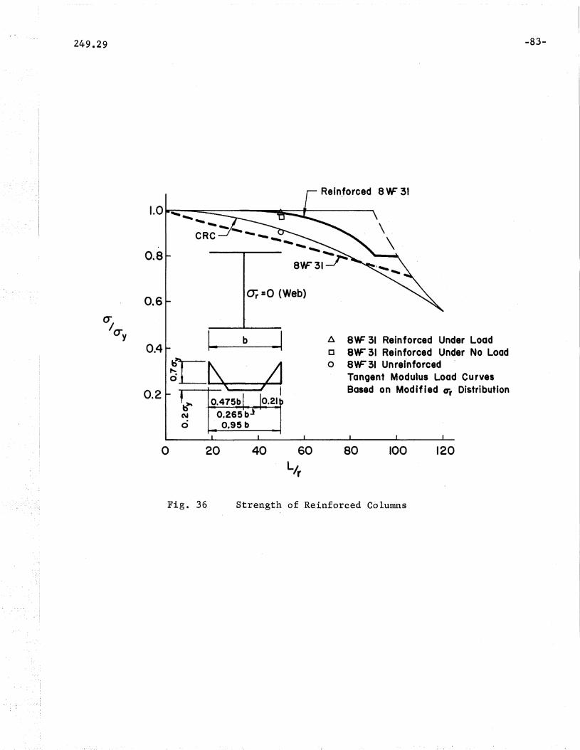
249.29
0.8
0.6
0.4
0.2b~
No
or =0 (Web)
1_ b
O.475bO,265bJ
0.95 b
SYF31
A 8YF 31 Reinforced Under LoadCI 8YF 31 Reinforced Under No Loado 8YF 31 Unrei-nforced
Tanoent Modulus Load CurvesBased on Modified CTr Distribution
-83-
o
Fig. 36 Strength of Reinforced Columns
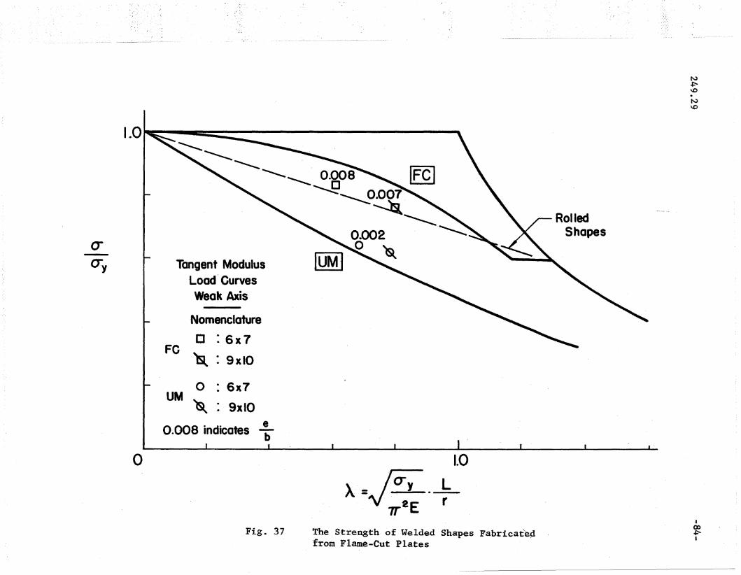
Tangent ModulusLoad' CurvesWeak Axis
(J-U:y
I-0 I""'b:: ,
~ ~ fFCl-----........... . 0.008 ~~
"'-"'----- [J 0 007 _---~~
~.~0.002o ~
Nomenclature
[J :6x7-FC 'lsl : 9 xlO
RolledShapes
f',)
~\0.N\0
o
o : 6x7UM~ : 9xl0
0.008 indicates t
\-1\-U y
7T2E
1.0
L--rFig. 37 The S~rength of Welded Shapes Fabricat~d
from Flame-Cut Plates
-Ico~I

1.0'" cc:: •
(T-tTy
IWeak-Axis I
GQLWIIIN C 414·lx 15-1
• H
FULL PENETRATION -WELD
A36
-- :rM Load Based
on Varying CTr
tv~\0.N\.0
0.5A t.O 1.5
Fig. 38 Comparison of Theoretical TM Load Curves for C4
J(X)V1I

N+:""'\0.N\.0
---- elastic buckling
';'-,--~-- elastic - plastic
5- I, 5-11: d' =0.23y
b/t=45. { 0" : Critical Stress
• : Ultimate Str~ss
5-2 5-21: ~I =0.16, vy
_ b/t =64
{_A : Critical Stress.. : Ultimate Stress
Uri =0.23tTy
b Uy 36Tfor E =
20 40.- I I -- ------~ I -I
o 1.-0 2.0 3D 4.0 5.0
!..~cry.t --_ E
A1.00
0.50 _CTcrcry
Fig. 39 Plate Buckl~ng Curve with Test. Points (A36 Steel)t
00(J\
I

N+:-\0.N\.0
1.00 _._.-.-._.
<Tcr 0.50cry
(Ty 110+for E = 30,000
20
<Tri =0.15tJy
t <Tri =0.10(J.y_
U'rlT-2A·,T-2B: <Ty =0.15
b~ =26To: Critical Stress1. • ': Ultimate Stress
- CTr• .T-IA,T-IB: a=- =0.10
yb/t =44
{6. : Critical Stress
• : Ultimate Stress
elastic bucking
----- elastic- plastic
~- ------- • -T----- I 1 I
o 1.0 2.0 3,"0 4.0 5.0
Fig. 4-0
~~(jyt-rPlate Buckling Curve with L~st Points (A5l4- Steel)
Ico-.....JI
8 1I REFEREJ:\JCES
1. A. W. Huber, Lo S. BeedleRESIDUAL STRESS AND THE COMPRESSIVE STRENGTH OF STEELWelding Journal, Vol. 33, DeG. 1954
2. L. S. Beedle, L. TallBASIC COLUMN STRENGTHASCE Prac., ST7, Volo 86, July 1960
3. Lo TallSTUB COLUMN TEST PROCEDUREFritz Laboratory Report No. 220A.36, Feb. 1961.Also Document X-282-6l, International Institute ofWelding, Oslo, July 1962.Also, Appendix of Ref. 18, ("eRG Guide ll
)
4. L. TallRECENT DEVELOP:MENTS IN THE STUDY OF COLUMN BEHAVIORJournal, Institution of Engineers, Australia, Vol. 36,Dec. 1954
5. No Ro NagarajaRao, F~ R•. ,Estuar, L. TallRESIDUAL STRESSES IN WELDED SHAPESWelding Journal, Vol. 43, July 1964
6. No Ro NagarajaRao, Lo TallRESIDUAL STRESSES IN WELDED PLATESWelding Journal, Vol. 40, Oct. 1961
7 • L. TallRESIDUAL STRESSES IN WELDED PLATES A THEORETICAL·STUDYWelding Journal, Vol. 43, Jan. 1964
8. N. Ro NagarajaRao, L. TallRESIDUAL STRESSES IN AUTOMATICALLY WELDED PLATESFritz Laboratory Report No. 249.22, in preparation
9. Eo Odar, F. Nishino, Lo TallRESIDUAL STRESSES IN T-l CONSTRUCTIONAL ALLOYSTEEL ,PLATESFritz Laboratory Report No. 290.4, Jan. 1965(To be published in Welding Journal)
10. N. Ro Nagar?jaRao, L. TallCOLUMNS REINFORCED UNDER LOADWelding Journal, Volo 42, April 1963
-88 ...
-89-
11. L. TallTHE STRENGTH OF WELDED BUILT-UP COLUMNSPh.D. Dissertation, Lehigh University, May 1961
12. F. R Q • Estuar \WELDING RESIDUAL STRESSES AND THE STRENGTH OF HEAVYCOLUMN SHAPESPh.D o Dissertation, Lehigh University, Sept. 1965
13. ASTMMETHODS AND DEFINITIONS FOR MECHANICALTESTING OF STEEL PRODUCTSA370-65
14. N~ R Q NagarajaRao, Mo Lohrmann, L. TallEFFECT OF STRAIN' RATE ON THE YIELD STRESS OF STRUCTURALSTEELASTM Journal of Materials, Vol. 1, No.1, March 1966
15. Lv Tall, Editor-in-ChiefSTRUCTURAL STEEL DESIGNRonald Press, 1964
16. F. BleichBUCKLING STRENGTH OF METAL STRUCTURESMcGraw-Hill, 1952
17. F Q R. ShanleyINELASTIC COLUMN THEORYJournal, Aeronautical Sciences, Vol. 14, May 1947
18. B. Go Johnston, EditorGUIDE TO DESIGN CRITERIA FOR METAL COMPRESSION MEMBERS,COLUMN RESEARCH COUNCIL, 2nd EditionWiley, 1966
19. . Column Research CouncilTHE BASIC COLUMN'FORMULACRC Tech. Memo. No.1, May 1952
20. L. Tall, A. W. Huber, L. S. BeedleRESIDUAL ,STRESS AND THE INSTABILITY OF AXIALLYLOADED COLUMNSFritz Laboratory Report 220A.35, Feb. 1960.Also, International Institute of Welding Colloquium,Liege, Belgium, June 1960, Commission X Document"
·21. C. Ho Yang, Lo S. Beedle, Bo G. JohnstonRESIDUAL STRESS AND THE YIELD STRENGTH OF STEEL BEAMSWelding Journal, Vol •. 3l, April 1952

-9-0-
22. AISCSPECIFICATION FOR THE DESIGN, FABRICATION AND ERECTIONOF STRUCTURAL STEEL FOR BUILDINGSAISC, 1961, revised 1963
23. D. Feder, G. C. LeeRESIDUAL STRESS AND THE STRENGTH OF MEMBERS OF HIGHSTRENGTH STEELFritz Laboratory Report 269.2, March 1959'
24. L. S. Beedle, T. V. Galambos, L. TallCOLUMN STRENGTH OF CONSTRUCTIONAL STEELSSteel Design and Engineering Seminar, U. S. SteelCorp., Pittsburgh, May 1961
25. Y. FujitaBUILT-UP COLUMN STRENGTHPh.D. Dissertation, Lehigh University, Aug. 1956
26. F. R. Estuar, L. TallTHE STRENGTH OF WELDED ,BUILT-UP COLUMNSFritz Laboratory Report 249.16, in preparation
27. F. R. Estuar, L. Tall.EXPERIMENTAL INVESTIGATION OF WELDED BUILT-UP COLUMNSWelding Journal, Vol. 42, April 1963
28. T. W. Wilder, W. Ao Brooks, Eo E. MathauserTHE EFFECT OF INITIAL CURVATURE ON THE STRENGTH OFAN INELASTIC COLUM:NNACA Tech. Note No. 2872, Jan. 1953
29. A. W. Huber, R. Lo KetterTHE INFLUENCE OF RESIDUAL STRESS ON THE CARRYINGCAPACITY OF ECCENTRICALLY LOADED COLUMNSIABSE Publications, Zurich, Dec. 1958
30. A. NittaULTIMATE STRENGTH OF HIGH-STRENGTH STEEL CIRCULARCOLUMNSPh.D o Dissertation, Lehigh University, Oct. 1960
31. J. H. Pie1ertTHEORETICAL LOAD-DEFLECTION RELATIONSHIPS FOR WELDEDBOX COLUMNS WITH INITIAL DEFORMATIONM.S e Thesis, Lehigh University, Sept. 1965
32. B. G. JohnstonBUCKLING BEHAVIOR ABOVE tANGENT MODULUS LOADASCE Proc., Va 1. 87, EM6, Dec',. 1961

-91-
33. L. Tall, F~ R. EstuarDISCUSSION TO REF. 32Proc. ASCE, Vol. 88, EMS, Oct. 1962
34. F. NishinoBUCKLING STRENGTH OF COLUMNS AND THEIR COMPONENT PLATESPh.D. Dissertation, Lehigh University, Oct. 1964
35. N. R. NagarajaRaoTHE STRENGTH OF HYBRID STEEL COLUMNSPh.D. Dissertation, Lehigh University, May 1965
36. Y. FujitaULTIMATE STRENGTH OF COLUMNS WITH RESIDUAL STRESSESJournal, Society of Naval Architects of Japan, Jan. 1960
37. A. W. HuberTHE INFLUENCE OF RESIDUAL STRESS ON THE INSTABILITY OFCOLUMNSPh.D. Dissertation, Lehigh University, Aug. 1956
38. R. W. Frost, C. G. SchillingBEHAVIOR OF HYBRID BEAMS SUBJECTED TO STATIC LOADSASCE Proc. paper 3938, Vol. 90, ST3, June 1964
39. Y. UedaELASTIC, ELASTIC-PLASTIC, AND PLASTIC BUCKLING OFPLATES WITH RESIDUAL STRESSESPh.D. Dissertation, Lehigh University, Aug. 1962
40. Y, Ueda, L. TallBUCKLING OF PLATES WITH RESIDUAL STRESSESFritz Laboratory Report 290.2, Dec. 1964, revisedJan. 1966
41. F. Nishino, Y. Ueda, L. TallEXPERIMENTAL INVESTIGATION OF THE BUCKLING -OF PLATESWITH RESIDUAL STRESSESFritz Laboratory Report 290.3, April 1966. To bepublished by ASTM.
42. F. Nishino, L. TallRESIDUAL STRESSES AND THE LOCAL BUCKLING STRENGTH OFSTEEL ,COLUMNSFritz Laboratory Report 290.11, in preparation~