Σ-ii series sgdh user’s manual supplement for linear...
TRANSCRIPT

Σ-II SeriesSGDH User’s Manual Supplement for Linear Sigma SeriesUpon receipt of the product and prior to initial operation, read these instructions thoroughly, and retain for future reference.
YASKAWA manufactures component parts that can be used in a wide variety of industrial applications. The selection and application of YASKAWA prod-ucts remain the responsibility of the equipment designer or end user. YASKAWA accepts no responsibil ity for the way its products are incorporated into the final system design.
Under no circumstances should any YASKAWA product be incorporated into any product or design as the exclusive or sole safety control. Without excep-tion, all controls should be designed to detect faults dynamically under all cir-cumstances. All products designed to incorporate a component part manufactured by YASKAWA must be supplied to the end user with appropriate warnings and instructions as to that part’s safe use and operation. Any warn-ings provided by YASKAWA must be promptly provided to the end user.
YASKAWA offers an express warranty only as to the quality of its products in conforming to standards and specifications published in YASKAWA’s manual. NO OTHER WARRANTY, EXPRESS OR IMPLIED, IS OFFERED. YASKAWA assumes no liability for any personal injury, property damage, losses, or claims arising from misapplication of its products.
This manual deals with the stand-alone installation, wiring, test run, etc., of a unified linear/rotary-type AC servomotor. See the following manual for other items.• Sigma II Series Servo System Users Manual (YEA-SIA-S800-32.2B)
WARNING

i
1. Interpretation of Model Number ..........................................................11.1 Linear Motor Models ....................................................................................... 1
1.1.1Motor Coils ................................................................................................... 11.1.2Magnet Tracks ............................................................................................. 1
1.2 Core-less Type ............................................................................................... 21.2.1Motor Coil ..................................................................................................... 21.2.2Magnet Track ............................................................................................... 2
1.3 T-Type Iron Core ............................................................................................ 31.3.1Motor Coil ..................................................................................................... 3
1. 3. 1.1TYPE: SGLTW-20AA(P), SGLTW -35AA(P) ................. 31. 3. 1.2TYPE: SGLTW-40AA(P), SGLTW -80AA(P) ................. 3
1.3.2Magnet Track ............................................................................................... 41.4 F-Type Iron Core ............................................................................................ 5
1.4.1Motor Coil ..................................................................................................... 51.4.2Magnet Track ............................................................................................... 6
1.5 Servo Amplifiers .............................................................................................. 71.6 Serial Converter Unit ...................................................................................... 9
2. Wiring ...............................................................................................112.1 Connection With Peripheral Devices ............................................................ 11
2.1.1Single-Phase Main Circuit (115V or 208V) Specification ........................... 112.1.2Three-Phase Main Circuit (208V) Specification ......................................... 12
2.2 Standard Connection Examples ................................................................... 132.2.1Single-Phase Power Specification ............................................................. 132.2.2Three-Phase Power Specification .............................................................. 142.2.3In Position Control Mode ............................................................................ 152.2.4In Speed Control Mode .............................................................................. 162.2.5In Force Control Mode ............................................................................... 17
3. Linear Motor Setup ...........................................................................183.1 Installation and Setting ................................................................................. 18
3.1.1Motor Mounting and Encoder Mounting ..................................................... 183.1.2Setting of Linear Encoder Scale Pitch ........................................................ 183.1.3Verification of Feedback Pulse ................................................................... 18
3.2 Test Run Using Panel Operator .................................................................... 19
Table Of Contents

ii
4. Parameter Setting and Description of Functions ..............................204.1 Linear Motor Polarity Detection (only when there is no Hall sensor) ............ 204.2 Calculation of Needed Regenerative Resistor Capacity ............................... 21
4.2.1Study by Regenerative Energy Calculation ................................................ 214. 2. 1.1Calculation Procedure ........................................................................ 21
4.2.2Linear Motor Winding Resistance Loss ...................................................... 234. 2. 2.1SGLGW-Type Linear Motors ............................................................. 234. 2. 2.2SGLTW-Type Linear Motors .............................................................. 244. 2. 2.3SGLFW-Type Linear Motors .............................................................. 25
4.2.3Energy Absorbable by Servo Amplifier ...................................................... 264. 2. 3.1100V Servo Amplifiers ....................................................................... 26
5. Differences Between Rotary Motors and Linear Motors ...................285.1 Terms/Units .................................................................................................. 285.2 User Parameters ........................................................................................... 28
5.2.1User Parameter List ................................................................................... 285.2.2Switch List .................................................................................................. 345.2.3Input Signal Selection List .......................................................................... 395.2.4Output Signal Selection List ....................................................................... 415.2.5Auxiliary Function List ................................................................................ 425.2.6Monitor Mode List ....................................................................................... 43
5.3 Alarm Display List ......................................................................................... 445.4 Warning Display List ..................................................................................... 47
6. Ratings and Specifications ...............................................................486.1 Linear Motors ................................................................................................ 48
6.1.1SGLGW-Type Linear Motor ....................................................................... 486. 1. 1.1Standard Linear Motor Ratings/Specifications ................................... 486. 1. 1.2Force–Speed Characteristics ............................................................. 496. 1. 1.3Dimensional Drawing of Motor (SGLGW–AA) .............. 506. 1. 1.4Dimensional Drawing of Magnet Track (SGLGM–A) ....... 516. 1. 1.5 Structural Diagram of SGLGW .......................................................... 52
6.1.2 SGLTW-Type Linear Motor ....................................................................... 536. 1. 2.1Standard Linear Motor Ratings/Specifications ................................... 536. 1. 2.2Force/Speed Characteristics .............................................................. 556. 1. 2.3Dimensional Drawing of Motor 1 (SGLTW–A) .............. 566. 1. 2.4Dimensional Drawing of Motor 2 (SGLTW–AA) ........... 576. 1. 2.5Dimensional Drawing of Magnet Track (SGLTM–A)
(Applicable only to North American Markets) ..................................... 58

iii
6.1.3SGLFW-Type Linear Motor ........................................................................ 606. 1. 3.1Standard Linear Motor Ratings/Specifications ................................... 606. 1. 3.2Force/Speed Characteristics .............................................................. 616. 1. 3.3Motor Dimensional Drawing (SGLFW–AA) .................. 626. 1. 3.4Dimensional Drawing of Magnet Track (SGLFM–A) ........ 66
6.1.4Mechanical Limitations ............................................................................... 676. 1. 4.1Shock Resistance .............................................................................. 676. 1. 4.2Vibration Resistance .......................................................................... 676. 1. 4.3 Installation .......................................................................................... 67
6.2 Serial Converter Unit (JZDP-A004- ) ................................................. 686.2.1Characteristics/Specifications .................................................................... 686.2.2Analog Input Timing ................................................................................... 696.2.3Cautionary Items on Usage ........................................................................ 696.2.4Dimensional Drawings ............................................................................... 70
6. 2. 4.1JZDP-A004 (North American Market Standard) ................................ 706.3 Suggested Cables ........................................................................................ 71
6.3.1Suggested Cable List ................................................................................. 716.3.2Dimensional Drawings of Suggested Cables ............................................. 73
6. 3. 2.1Cable with Terminal on Both Ends② ................................................. 736. 3. 2.2Hall Sensor-Dedicated Cable③ ......................................................... 736. 3. 2.3Encoder-Dedicated Cable④ .............................................................. 73

iv
Safety-Related SymbolsThe following symbols are used in this manual according to the safety-related content.Be sure to observe text annotated with these safety symbols as their content is important.
Mis-operation may result in a hazardous condition with the possibility of death or serious injury.
Mis-operation may result in a hazardous condition with the possibility of serious or light injury as well as material damage.
Items marked with may entail serious ramifications. As either of these symbols contains important content, be sure to observe them.
WARNING
CAUTION
CAUTION

v
Icon DisplayThe following icons have been designed so that the classification of the content of the explanation can be easily discerned. The icons are displayed at needed locations to assist in comprehension.
Important matters to be memorized. In addition, this item serves as a light warning of a level not entailing damage to the machine, such as an alarm display, etc.
Displays programming examples, operation examples, etc.
Shows supplementary items and convenient functions.
Terminology?? Explanation of difficult to understand specialist terminology, as well as for technical terms that were not previously explained.
Important
Exp.
Supp.

vi
Outline of Manual Thank you for purchasing our unified Linear/RotaryΣ-Ⅱtype AC servo amplifier.
This manual deals with the stand alone installation, wiring, test run, etc., of a Plug&Play linear/rotary-type Σ-II series AC servo. See the following manuals for other items.
Document Name Document Number Content
Σ-Ⅱ Series SGMH/SGDHUser's ManualServo Selection and Datasheets
SI-S800-32.1 Explains selection of the Σ-II series servo device type and capacity.
Σ-Ⅱ Series SGMH/SGDHUser's ManualDesign/Maintenance
SI-S800-32.2
Explains Σ-II series servo installation, wiring, test run, usage of the various functions, as well as maintenance and testing.

vii
Safety NotesThis manual deals with cautionary items that must be observed in using the product, as well as in inspection upon receipt, installation, wiring, running, maintaining, and testing.
Inspection Upon Receipt of Product
Installation
Wiring
Running
• Use the linear motor and servo amplifier in a designated combination.Failure to due so may result in fire or unit failure.
• Never use this product in an area exposed to water, where the atmosphere is corrosive or flammable, or next to inflammable substances.
Failure to observe this may result in electrical shock and/or fire.
• Be sure to connect the grounding terminal to the grounding pole (D-class grounding).
Failure to observe this may result in electrical shock and/or fire.
• Do not connect the three-phase power supply to servo amplifier output terminals U, V, and W.
Doing so may result in injury and/or fire.
• Securely tighten the screws on the power terminals and motor output terminals.Failure to due so may result in fire.
• To prevent unexpected accidents, operate after mounting limit switches or stoppers to the ends of the slider.
Failure to do so may result in injury.
• When operating the device after installation on its counterpart machine, set user parameters matching that machine beforehand.
Operating without setting these parameters may result in machine runaway or failure.
CAUTION
CAUTION
WARNING
CAUTION
CAUTION

viii
Maintenance/Inspection
General Cautionary Items
• Before starting operation after installing the unit on its counterpart machine, always have the device in a state capable of emergency stop.
Failure to do so may result in injury.
• Do not touch the heat sink during operation.This may result in burns due to high temperatures.
• Never touch the interior of the servo amplifier.Failure to do so may result in electrical shock.
• Be sure the terminal cover is in place when power is fed.Failure to do so may result in electrical shock.
• Do not touch the terminals until at least 5 minutes after power shutoff.Failure to do so may result in electrical shock due to residual voltage.
• Do not modify the wiring while power is ON.Doing so may result in electrical shock or injury.
Keep in Mind While Using the Product
• Because the diagrams in this manual describe detailed items, they are sometimes drawn with covers and safety shields removed. When operating this product, be sure that all safety covers and shields are returned to their original positions before operating.
• The figures displayed in this manual are representative examples, and may differ from the product received.
• This manual may be revised where appropriate due to product improvements, specification changes, or for purposes of improved ease of use for the manual itself. The document number will be updated and issued as a revision with regard to these changes.
• To order a new manual due to damage or loss of this one, please contact the nearest Yaskawa sales office listed on the back of this manual with the document number listed on the front.
• Yaskawa assumes no responsibility for modifications made to the product by the customer as they fall outside the scope of the warranty.
CAUTION
WARNING
CAUTION

ix

1.1.1 Motor Coils
1
1. Interpretation of Model NumberThe model numbering conventions are shown below
1.1 Linear Motor Models
1.1.1 Motor Coils
1.1.2 Magnet Tracks
SGL G W - 40 A 140 A WLinear Σ-Series ServoMotor
W: Motor Coils
Height of Magnets Design Revision Order
Coil LengthVoltageA:200V~240VAC
ModelG: Coreless GW
F: Iron Core FWT: Iron Core FW
W: With Hall Sensor module and a SerialConverter module (standardconfiguration) The serial converter isrequired for operation with Sigma-IIdrives.
P: With a Hall Sensor module only,without a serial converter (when orderfor a replacement motor coil only)Always use "W" for normal orders.
SGL G M - 40 225 A C
M: Magnet Track
Motor Magnet Width20: 20mm35: 35mm40: 40mm50: 50mm60: 60mm80: 80mm
Options (Standard on Coreless F and T types only)C: With magnet coversY: With base and magnet covers
Design Revision OrderLength of MagnetsTracks in mm(See drawings on later pages)
Motor TypeG: Coreless GW
F: Iron Core FWT: Iron Core TW
Linear Σ-Series ServoMotor

2
1.2 Core-less Type
1.2.1 Motor Coil
1.2.2 Magnet Track
ModelSGLGW-
Peak Force(N)
Continuous Force
(N)
External Dimensions (mm) Mass(Kg)L1 L2 H
40A140A(P) 140 47 140 125 63 0.3940A253A(P) 280 93 252.5 237.5 63 0.6540A365A(P) 420 140 365 350 63 0.9160A140A(P) 220 73 140 125 83 0.4760A253A(P) 440 147 252.5 237.5 83 0.8060A365A(P) 660 220 365 350 83 1.13
ModelSGLGM-
External Dimensions (mm) Mass(Kg)L W H
40090A 90 25.4 62 0.840225A 225 25.4 62 2.040360A 360 25.4 62 3.140405A 405 25.4 62 3.4
L116
H
25.4
L2
15
30
Hall Sensor
L W
H
-0.1-0.3
3
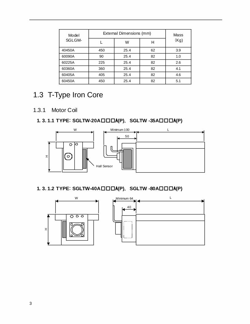
1.3 T-Type Iron Core
1.3.1 Motor Coil
1. 3. 1.1 TYPE:::: SGLTW-20AAAAA(P),,,, SGLTW -35AAAAA(P)
1. 3. 1.2 TYPE:::: SGLTW-40AAAAA(P),,,, SGLTW -80AAAAA(P)
40450A 450 25.4 62 3.960090A 90 25.4 82 1.060225A 225 25.4 82 2.660360A 360 25.4 82 4.160405A 405 25.4 82 4.660450A 450 25.4 82 5.1
ModelSGLGM-
External Dimensions (mm) Mass(Kg)L W H
LMinimum 100
50
W
H
Hall Sensor
L
40
Minimum 64W
H
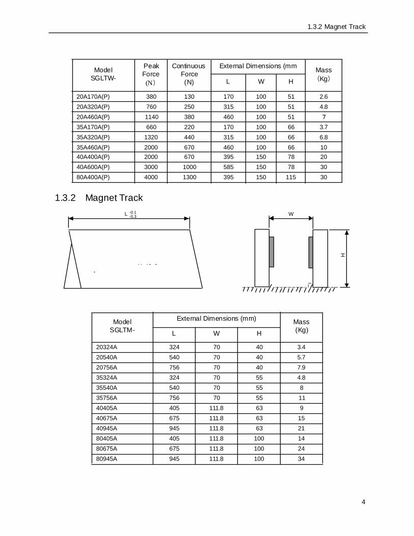
1.3.2 Magnet Track
4
1.3.2 Magnet Track
ModelSGLTW-
Peak Force(N)
Continuous Force(N)
External Dimensions (mm Mass(Kg)L W H
20A170A(P) 380 130 170 100 51 2.620A320A(P) 760 250 315 100 51 4.820A460A(P) 1140 380 460 100 51 7
35A170A(P) 660 220 170 100 66 3.735A320A(P) 1320 440 315 100 66 6.835A460A(P) 2000 670 460 100 66 1040A400A(P) 2000 670 395 150 78 2040A600A(P) 3000 1000 585 150 78 3080A400A(P) 4000 1300 395 150 115 30
ModelSGLTM-
External Dimensions (mm) Mass(Kg)L W H
20324A 324 70 40 3.420540A 540 70 40 5.720756A 756 70 40 7.935324A 324 70 55 4.835540A 540 70 55 835756A 756 70 55 1140405A 405 111.8 63 940675A 675 111.8 63 1540945A 945 111.8 63 2180405A 405 111.8 100 1480675A 675 111.8 100 2480945A 945 111.8 100 34
L W
H
-0.1-0.3

5
1.4 F-Type Iron Core
1.4.1 Motor Coil
ModelSGLFW-
Peak Force
(N)
Continuous Force
(N)
External Dimensions (mm) Mass(Kg)L W H
20A090A(P) 86 25 91 40 34 0.720A120A(P) 125 40 127 40 34 0.935A120A(P) 220 80 127 55 34 1.335A230A(P) 440 160 235 55 34 2.350A200A(P) 600 200 215 71.5 43 3.750A380A(P) 1200 400 395 71.5 43 6.91ZA200A(P) 1200 400 215 119 43 6.41ZA380A(P) 2400 800 395 119 43 12.2
L W
H
Minimum 50
Hall Sensor

1.4.2 Magnet Track
6
1.4.2 Magnet Track
ModelSGLFM-
External Dimensions (mm) Mass(Kg)L W H
20324A 324 44 10 0.920540A 540 44 10 1.420756A 756 44 10 235324A 324 60 10 1.235540A 540 60 10 235756A 756 60 10 2.950405A 405 75 14 2.850675A 675 75 14 4.650945A 945 75 14 6.51Z405A 405 125 14 7.31Z675A 675 125 14 121Z945A 945 125 14 17
L
W
H
-0.1-0.3

7
1.5 Servo Amplifiers
Maximum Capacity of Applied Motor
Maximum Capacity Symbol on Applied
Motor
Capacity (kW)
Maximum Capacity Symbol on Applied
Motor
Capacity (kW)
01 0.10 15 1.502 0.20 20 2.004 0.40 30 3.005 0.45 50 5.008 0.75 75 7.510 1.0
SGDH - 10 AΣ-II SeriesSGDH Servo Amplifier
Maximum Applicable Motor Capacity(see table below)Voltage A: 208~240VAC B: 115V ∗ ∗ 0.2kW or less for 115V
E
Model E: Force/Speed/Position Control (option unit-compat ible)

1.4.2 Magnet Track
8
Applied Motor Types
Motor Model Applicable Servo Amplifier
SGLGW-
40A140A SGDH-01AE40A253A SGDH-02AE40A365A SGDH-04AE60A140A SGDH-02AE60A253A SGDH-04AE60A365A SGDH-08AE
SGLTW-
20A170A SGDH-05AE20A320A SGDH-10AE20A460A SGDH-15AE35A170A SGDH-08AE35A320A SGDH-15AE35A460A SGDH-20AE40A400A SGDH-20AE40A600A SGDH-30AE80A400A SGDH-50AE80A600A SGDH-75AE
SGLFW-
20A090A SGDH-02AE20A120A SGDH-02AE35A120A SGDH-02AE35A230A SGDH-05AE50A200A SGDH-08AE50A380A SGDH-15AE1ZA200A SGDH-15AE1ZA380A SGDH-20AE

9
1.6 Serial Converter Unit
Serial Converter Units Classified by Model and Shape
Serial Converter Units and Applicable Motor Chart
The serial converter contains the motor ID, winding data, as well as the data that enables the system to be Plug and Play. When used with Yaskawa’s SGDH Servo Drive, the correct Serial Converter must also be used to operate the system. Mis-matching the motor coil and serial converter will cause system malfunction. To ensure the proper match, a serial converter with the correct P/N and a motor coil are shipped together from the factory.
Model Shape Scale Used Servo Sensor (Y/N)
JZDP-A004
Renishaw (Conversion cable for Heiden-hain scales is available)
Y
JZDP -
Converter Unit Type(see table below)
AOO4
Compatible Motor NumberVaries according to the compatiblemotor (see table below)
-

1.4.2 Magnet Track
10
Serial Converter Units and Applied Motors
Serial Converter Unit Model JZDP-A004-
Applied Motor Serial Converter Unit Model JZDP-A004-
Applied Motor
001 SGLGW-40A140A(P) 013 SGLTW-20A460A(P)002 SGLGW-40A253A(P) 014 SGLTW-35A170A(P)003 SGLGW-40A365A(P) 015 SGLTW-35A320A(P)004 SGLGW-60A140A(P) 016 SGLTW-35A460A(P)005 SGLGW-60A253A(P) 017 SGLFW-20A090A(P)006 SGLGW-60A365A(P) 018 SGLFW-20A120A(P)007 SGLTW-40A400A(P) 019 SGLFW-35A120A(P)008 SGLTW-40A600A(P) 020 SGLFW-35A230A(P)009 SGLTW-80A400A(P) 021 SGLFW-50A200A(P)010 SGLTW-80A600A(P) 022 SGLFW-50A380A(P)011 SGLTW-20A170A(P) 023 SGLFW-1ZA200A(P)012 SGLTW-20A320A(P) 024 SGLFW-1ZA380A(P)

11
2. Wiring
2.1 Connection With Peripheral Devices
2.1.1 Single-Phase Main Circuit (115V or 208V) Specification
Digital Operator
Se t s th e va r io u s u s erp a rame t ers , d i sp la y so p era t io n st at u s, a ndalarms. Can communic atewith PC.
W iring Breaker (MCCB)Connected to mot ion module MP91 0,MP92 0,MP930,MP-SG1
Personal Computer
Use d fo r p ower linep rot ection . Shu tsOFF the lin e in thee ve nt o fo ve rc urrent.
Noise Fil terAt tac he d to p reve nt e xtern aln oise f rom the powe r line
MagneticContac tor
Turn s servo po we rON/OFF. Use with as u rge su p re ss o ra ttache d
HI Ser ies
Sing le- Pha seSing le- Pha seSing le- Pha seSing le- Pha seSou rc e Sou rc e Sou rc e Sou rc e AC200 V
Ma g ne t i cContac tor
WiringBreake r
N o i s eF i l t e r
SourceGrounding
Line
R S T
Upper-LevelDevice
Conne ctble to Yaska wa up per -level d evice
U V W
L1 L2 L1C L2CB1 B2
Regene ra tiv eResis tor(opt ional)
Con nec tor Cable Mod el: JZSP-CMS01~03
JUSP-O P02A-2
Core-less LinearMotor
4P4P回生抵抗器
内蔵回生抵抗器の容量が不足する場合は,B2 - B3端子の接続をはずし,B1-B2端子に外置き回生抵抗器を接続します。
Conn ect an extern alregen erat ive resistor betweentermin als B1-B2 if rege rat ivecapac ity is insu fficie nt.
Regenerative Res is tor
Se ria lConverterUnit
Hall Se ns orUnit
The cus tomermust provide thefol lowing:・Linear measuring system・Linear guides
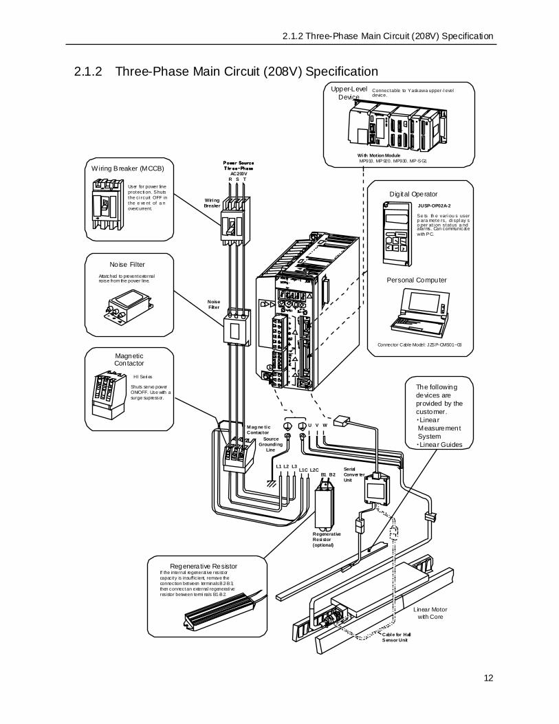
2.1.2 Three-Phase Main Circuit (208V) Specification
12
2.1.2 Three-Phase Main Circuit (208V) Specification
回生抵抗器
R S T
U V W
L1 L2 L3L1C L2C
B1 B2
内蔵回生抵抗器の容量が不足する場合は,B2-B3端子の接続をはずし,B1-B2端子に外置き回生抵抗器を接続します。
Dig ital OperatorJUSP-OP02A-2
Se ts th e vari ou s userp ara mete rs, di spl ay so per at i on status a ndalarms. Can communicatewith PC.
Personal Computer
Connector Cable Model: JZSP-CMS01~03
The followingdevices areprovided by thecustomer.・Linear Measurement System・Linear Guides
SerialConver terUnit
RegenerativeResistor(optional)
Linear Motorwith Core
Cable for HallSensor Unit
If the internal regenerat ive resistorcapacity is insuff icient, remove theconnection between terminals B2-B3,then connect an external regenerati veresistor between termi nals B1-B2.
Regenerative Resistor
SourceGrounding
Line
M ag ne ticContactor
Shuts servo powerON/OFF. Use with asurge supressor.
HI Seri es
MagneticContactor
NoiseFilter
Attatched to prevent externalnoise from the power line.
No ise Filter
User for power lineprotecti on. Shutsthe ci rcuit OFF inthe e ve nt of a novercurrent.
WiringBreaker
Wiring B reaker (MCCB)P ower SourceP ower SourceP ower SourceP ower SourceT hr ee-PhaseT hr ee-PhaseT hr ee-PhaseT hr ee-Phase
AC200V
With Motion Module MP910,MP920,MP930,MP-SG1
Connectable to Yaskawa upper-l eveldevice.
Upper-LevelDevice

13
2.2 Standard Connection ExamplesStandard connection examples for servo amplifiers are shown by specification.
2.2.1 Single-Phase Power Specification
* 1. represents a twisted pair wire.
* 2. The 1-time filter time constant is 47μs.
150Ω
150Ω
L1
L2
L1C
L2C
1
2
CN1
V -REF
S G
5
6LPF∗ 2
T-REF
S G
9
10LPF∗ 2
P
P
A/D
P ULS
/PULS
7
8
S IGN
/SIGN
11
12
P
P
CLR
/CLR
15
14P
150Ω
PL1 3
PL2
PL3
13
18
+12V1KΩ
Speed Reference(±2V~±10V/Rated Speed)
Thrust Reference(±1V~±10V/Rated Thrust)
Always ground.
CWA-phase
PULSCW
SIGNCCWA-Phase
CLR
Power foropencol lectorcommand
Posit ionReference
3.3KΩ+24V
/S-ON
47
401Ry Servo ON
/P-CON 412Ry Proport ional control
(P operation)
P-OT 42P-LS Forward run prohibi t
N-OT 43N-LS Reverse runprohibi t
/ALM-RST 443Ry Alarm reset
/P-CL 456Ry Forward s ide
reverse limit ON
/N-CL 467Ry Reverse s ide reverse limitON
Servo ON at 1Ry ON.
+24V
P operat ion at 2Ry ON
Forward run prohibit at P-LSOFF
Reverse run prohib it at N-LS OFF
Alarm reset at 3Ry ON
Forward current limi t ON at6Ry
Reverse current l imit ON at7Ry
25
26
/V-CMP+(/COIN+)/V-CMP-(/COIN-)
Speed Coi nc idence Detection(ON at speed coi nc idence detection)Posi tioning Completion(ON at pos itioning completion)
27
28/TGON+ TGON Output
(ON when at or above the set va lue)/TGON-
29
30/S-RDY+ Servo Ready Output
(ON when ready)/S-RDY-
31
32ALM+
ALM-Servo Alarm Output(OFF at alarm)
Photocoupler Output Max. Usage V ol tage DC30V Max. Output Current DC50mA
37
38ALO1
ALO2
U
V
W
M
A (1)
B (2)
C (3)
D (4)
Motor
Linear Scal eS erial Converter UnitCN2
Perform proper termi nalprocessi ng of the shi eld
wires
39 ALO3
A larm Code output
Max. Usage Voltage DC30VMax. Output Current DC20mA
33
34PAO
/PA O35
36PBO
/PB O19
20PCO
/PCO
Encoder Div ided outputApplied Line Receiver TI -made SN75175 or MC3486 equivalent dev ice
1MC SUP
1MCA larm
ProcessingPowerOFF
PowerON
NoiseFil ter
1MC
1MCCB
Servo AmplifierSGDH
B1 B2
At tach a surge suppressor to the the magneti ccontactor and relay coil.
FG
Connector ModuleConnect t he shield wi re to theconnector module.
S ingle-Phase AC200V~230V(50/60Hz)
+1 0%-15 %
o r S in gle - Ph a se AC 1 00 V~1 1 5V(5 0/ 60 H z)
+10 %-15%
∗ 1

2.2.2 Three-Phase Power Specification
14
2.2.2 Three-Phase Power Specification
* 1. represents a twisted pair wire.
* 2. The 1-time filter time constant is 47μs.
* 3. Connect an external regenerative resistor between terminal B1–B2 for servo amplifiers with capacities of 6.0kW or greater. (There is no terminal B3.)
Serial Converter Uni t
150Ω
150Ω
L1
L2
L1C
L2C
1
2
CN1V-REF
SG
5
6LPF∗ 2
T-REF
SG
9
10LPF∗ 2
P
P
A/D
PULS
/PULS
7
8
SIGN
/SIGN
11
12
P
P
CLR
/CLR
15
14P
150Ω
PL1 3
PL2
PL3
13
18
+12V
1KΩ
Speed Reference(±2V~±10V/Rated Speed)
T hrust Reference(±1V~±10V/Rated Thrust )
Always ground.
PULSCWA-Phase
SIGNCCWA-Phase
CLR
Power for OpenColl ectorReference
Position
Reference
3.3KΩ+24V
/S-ON
47
401Ry Servo ON
/P-CON 412Ry Proport ional Control(P operation)
P-OT 42P-LS Forward Run Prohibit
N-OT 43N-LS Reverse Run Prohibit
/ALM-RST 443Ry Al arm Reset
/P-CL 456Ry Forward Current Li mit
ON
/N-CL 467Ry Reverse Current Limit
ON
Servo ON at 1Ry ON
+24V
P Operat ion at 2Ry ON
F orward Run Prohibit at P-LSOF F
Reverse Run Prohi bi t at N-LSOF F
Alarm Reset at 3Ry ON
F orward Current Limit ON at 6Ry ON
Reverse Current Lim it at 7Ry ON
25
26
/V-CMP+(/COIN+)/V-CMP-(/COIN-)
Speed Coincidence Detection(ON at speed coinci dence detection)Positioning Completion(ON at positioning completi on)
27
28/TGON+ TGON Output
(ON at set value or higher)/TGON-
29
30/S-RDY+ Servo Ready Output
(ON at ready)/S-RDY-
31
32ALM+
ALM-Servo A larm Output(OFF at al arm)
Photocoupler Output Max. Usage Voltage DC30V Max. Output Current DC50mA
37
38ALO1
ALO2
U
V
W
M
A (1)
B (2)
C (3)
D (4)
Motor
Li near ScaleCN2
Properl y process theshield wire terminals
39 ALO3
Alarm Code OutputMax. Use Voltage DC30VMax. Output CurrentDC20mA
33
34PAO
/PAO35
36PBO
/PBO19
20PCO
/PCO
Encoder Divi ded OutputApplied Line Reci ver TI-made SN75175 or, M C3486 equivalent device
1M C SUP
1MCAlarm Processing
PowerOFF
PowerON
Noise Filter
1MC
1MCCB
Servo AmplifierSGDH
B1 B2
Attach a surge supressor to the magnet ic contactorand relay coi l.
FG
Connector Shell
Connect the shild line to theconnector shell
T hree-phase AC200V~230V(50/60Hz)
+10 %-15 %
L3
R S T
B3∗ 3
∗ 1

15
2.2.3 In Position Control Mode
* 1. represents a twisted pair wire.
* 2. The 1-time filter time constant is 47μs.
* 3. Connect an external regenerative resistor between terminal B1–B2 for servo amplifiers with capacities of 6.0kW or greater. (There is no terminal B3.)
* 4. Enabled by user parameter setting.
Serial Conversi on Unit
Posiitoning Complete(ON at posi tioning complet ion)
150Ω
150Ω
L1
L2
L1C
L2C
1
2
CN1
T-REF
SG
9
10LPF∗ 2
PA/D
PULS
/PULS
7
8
SIGN
/SIGN
11
12
P
P
CLR
/CLR
15
14P
150Ω
PL1 3
PL2
PL3
13
18
+12V1KΩ
External Thrust Limit /Thrust FeedF orward ∗ 4 (± 1V~±10V/Rated Speed)
Al ways ground.
PULSCWA-P hase
SIGNCCWA-Phase
CLR
Power for OpenCollectorCommand
Posi tionReference
3.3KΩ+24V
/S-ON
47
401Ry Servo ON
/P-CON 412Ry Proport ional Control
(P Control)
P-OT 42P-LS Forward Run Prohibit
N-OT 43N-LS Reverse Run
Prohibit
/ALM-RST 443Ry Alarm Reset
/P-CL 456Ry Forward CurrrentLimit ON
/N-CL 467Ry Reverse Current Lim it ON
Servo ON at 1Ry ON
+24V
P Operat ion at 2Ry ON
F orward Run Prohibit at P -LSOFF
Reverse Run Prohibit at N-LSOFF
A larm Reset at 3Ry ON
F orward Current LImit at 6RyON
Reverse Current Limit at 7RyON
25
26/COIN+
/COIN-
27
28/TGON+ TGON Output
(ON at or above setting va lue)/TGON-
29
30/S-RDY+ Servo Ready Output
(ON when ready )/S-RDY-
31
32ALM+
ALM-Servo Alarm Output(Alarm Off )
Photocoupler Output Maximum Usage Voltage DC30V Maximum Output Current DC50mA
37
38ALO1
ALO2
U
V
W
M
A (1)
B (2)
C (3)
D (4)
Motor
Linear ScaleCN2
Perform proper termi nalprocessing of shield wire.
39 ALO3
Al arm Code OutputMax. Usage Voltage DC30VMax. Output CurrentDC20mA
33
34PAO
/PAO35
36PBO
/PBO19
20PCO
/PCO
Encoder Divided OutputAppli ed Li ne Driver TI -made SN75175 or M C3486 equivalent
1MC SUP
1MCAlarm Processing
PowerOFF
PowerON
Noise Filter
1MC
1MCCB
B1 B2
At tach a surge supressor to the magneti c contactorand rel ay coil.
FG
Connector Shell
Connect the shi el d wi re to theconnector shell .
Three-phase AC200V~230V(50/60Hz)
+10 %- 15 %
L3
R S T
B3∗ 3
∗ 1
Servo AmplifierSGDH

2.2.4 In Speed Control Mode
16
2.2.4 In Speed Control Mode
* 1. represents a twisted pair wire.
* 2. The 1-time filter time constant is 47μs.
* 3. Enabled by user parameter setting.
* 4. Connect an external regenerative resistor between terminal B1–B2 for servo amplifiers with capacities of 6.0kW or greater. (There is no terminal B3.)
Serial Converter Unit
External Thrust Limit/Thrust Feed Forward∗ 3(±1V~±10V/Rated Speed)
L1
L2
L1C
L2C
1
2
CN1V-REF
SG
5
6LPF∗ 2
T-REF
SG
9
10LPF∗ 2
P
P
A/D
Speed Reference(±2V~±10V/Rated Speed)
Always ground.
3.3KΩ+24V
/S-ON
47
401Ry Servo ON
/P-CON 412Ry Proporti onal Control(P operat ion)
P-OT 42P-LS Forward Run Prohibit
N-OT 43N-LS Reverse Run Prohi bit
/ALM-RST 443Ry Alarm Reset
/P-CL 456Ry Forward Current Li mit
ON
/N-CL 467Ry Reverse Current LimitON
Servo ON at 1Ry ON
+24V
P Operat ion at 2Ry ON
Forward Run Prohi bi t at P-LSOFF
Reverse Run Prohibit at N-LSOFF
Al arm Reset at 3Ry ON
Forward Current Lim it at 6Ry ON
Reverse Current Li mit at 7RyON
25
26/V-CMP+
/V-CMP-Speed Coincidence Detect ion(ON at speed coincidence detect ion)
27
28/TGON+ TGON Output
(ON at or above set val ue)/TGON-
29
30/S-RDY+ Servo Ready Output
(ON when ready)/S-RDY-
31
32ALM+
ALM-Servo Al arm Output(OFF at al arm)
Photocoupler Output Max. Usage Voltage DC30V Max. Output Current DC50mA
37
38ALO1
ALO2
U
V
W
M
A (1)
B (2)
C (3)
D (4)
Motor
Linear ScaleCN2
Perfom proper terminalprocessi ng for shield wi re.
39 ALO3
Al arm Code OutputMax. Usage Voltage DC30VMax. Output CurrentDC20mA
33
34PAO
/PAO35
36PBO
/PBO19
20PCO
/PCO
Encoder Divi si on OutputAppl ied Line Receiver TI -made SN75175 or MC3486 equi valent
1MC SUP
1MCAlarm Processi ng
PowerOFF
PowerON
Noise FI lter
1MC
1MCCB
Servo AmplifierSGDH
B1 B2
Attach a surge supressor to the magnetic contactorand relay coil.
FG
Connector Shel l
Connect the shiel d wi re to theconnector shell.
T hree-Phase AC200V~230V(50/60Hz)
+10%-15%
L3
R S T
B3∗ 4
∗ 1
17
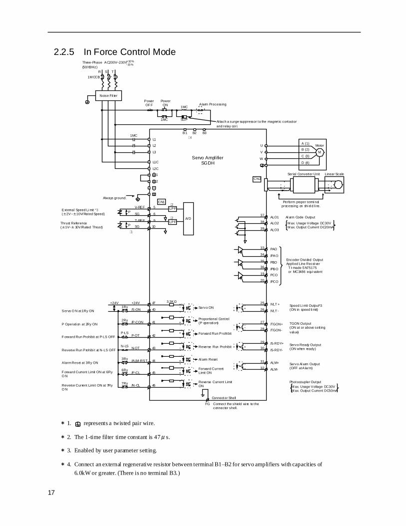
2.2.5 In Force Control Mode
* 1. represents a twisted pair wire.
* 2. The 1-time filter time constant is 47μs.
* 3. Enabled by user parameter setting.
* 4. Connect an external regenerative resistor between terminal B1–B2 for servo amplifiers with capacities of 6.0kW or greater. (There is no terminal B3.)
L1
L2
L1C
L2C
1
2
CN1V-REF
SG
5
6LPF∗2
T-REF
SG
9
10LPF∗2
P
P
A/D
External Speed Li mit *3(±2V~±10V/Rated Speed)
Always ground.
3.3KΩ+24V
/S-ON
47
401Ry Servo ON
/P-CON 412Ry Proportional Control(P operati on)
P-OT 42P-LS Forward Run Prohi bit
N-OT 43N-LS Reverse Run Prohibit
/ALM-RST 443Ry Al arm Reset
/P-CL 456Ry Forward Current
Limit ON
/N-CL 467Ry Reverse Current LimitON
Servo O N at 1Ry ON
+24V
P Operati on at 2Ry ON
F orward Run Prohibit at P-LS OFF
Reverse Run Prohibi t at N-LS OFF
Alarm Reset at 3Ry ON
F orward Current Limit ON at 6RyO N
Reverse Current Limi t ON at 7RyO N
25
26/VLT +
/VLT -Speed Li mit Output*3(ON in speed li mit)
27
28/TGON+ TGON Output
(ON at or above sett ingval ue)/TGON-
29
30/S-RDY+ Servo Ready Output
(ON when ready)/S-RDY-
31
32ALM+
ALM-Servo Al arm Output(OFF at Alarm)
Photocoupler Output Max. Usage Voltage DC30V Max. Output Current DC50mA
37
38ALO1
ALO2
U
V
W
M
A (1)
B (2)
C (3)
D (4)
Motor
Linear ScaleSerial Converter UnitCN2
Perform proper termi nalprocessing on shi el d li ne.
39 ALO3
Al arm Code Output
Max. Usage Voltage DC30VMax. Output Current DC20mA
33
34PAO
/PAO35
36PBO
/PBO19
20PCO
/PCO
Encoder Divi ded OutputAppli ed Line Recei ver T I-made SN75175 or MC3486 equi valent
1MC SUP
1MCAlarm Processing
PowerOF F
PowerON
Noise Fil ter
1MC
1MCCB
Servo AmplifierSGDH
B1 B2
Attach a surge suppressor to the magnet ic contactorand relay coi l.
FG
Connector Shell
Connect the shield wi re to theconnector shell.
Three-Phase AC200V~230V(50/60Hz)
+10%-15%
L3
R S T
B3∗ 4
∗1
Thrust Reference(±1V~±10V/Rated Thrust)

3.1.1 Motor Mounting and Encoder Mounting
18
3. Linear Motor Setup
3.1 Installation and Setting
3.1.1 Motor Mounting and Encoder MountingBe sure that the forward direction of the motor and of the encoder match when installing.
(1) See “6.1 Linear Motors” for the forward motor direction.
(2) See “6.2 Serial Converter Unit (JZDP-A004- )” for forward encoder direction.
3.1.2 Setting of Linear Encoder Scale PitchAfter completion of the installation and wiring, feed the control power only, and input the correct linear pitch (pn280) to be used for each application. Alarm A.80 (linear encoder scale pitch setting error will be output when the power is first input because the initial value is “0”. This will be resolved upon setting a normal value into Pn280 and cycling the power.
3.1.3 Verification of Feedback PulseThe feedback pulse verification method is shown below.
1. Connect the encoder wire to CN4.2. Verify whether the feedback pulse is received correctly by feeding control power and manually
move the motor.Verify the feedback pulse in user parameter Un00D (Feedback Pulse Monitor).Verify that the feedback pulse variation is the value set in Un00D by moving the motor for a desired distance.In addition, verify that the value of Un004 (Motor electrical angle monitor) returns to its original value by moving the motor across only two magnets on the motor magnet slide
Be conscientious in setup as linear motors can undergo various status changes due to the installation direction and encoder mounting direction.• Failure to do so may result in injury.
CAUTION
Supp.

19
3.2 Test Run Using Panel OperatorAfter setting the resolution and verifying the feedback pulse, perform a test run by the following operation.1. Feed main power2. Try moving the linear motor by operating the panel operator.3. Verify that the linear motor is working normally.
(1) When turning on the servo for the first time, stand away from the motor as motor runaway may occur.
(2) To prevent danger during motor setup, the factory settings for the force limit parameters (Pn483, 484) are extremely small (Factory Setting: 10%).
(3) Press the ↑ key on the panel operator, to raise the parameter to the force used when driving the motor forward.
(1) Perform magnetic polarity detection before moving the motor if no Hall sensor is used. For details, See “4.1 Linear Motor Polarity Detection (only when there is no Hall sensor)”
(2) Input signal verification and verification of operation by external command is the same as in a rotary motor. For details, see chapter -32.2 “Test Run” of “Σ-Ⅱ II Series SGMH /SGDH User's Manual Design/Maintenance (SI-S800-32.2)”. See “7.2.2 Test Run with Digital Operator” in the “ Σ-Ⅱ II Series SGMH /SGDH User's Manual Design/Maintenance (SI-S800-32.2)”.
Important
Supp.

3.1.3 Verification of Feedback Pulse
20
4. Parameter Setting and Description of Functions
Here we will describe the functions dedicated to the linear SGDH servo amplifier.See Chapter 5 “Parameter Setting and Description of Functions” in the “Σ-II Series SGMH /SGDH User's Manual Design/Maintenance (SI-S800-32.2)” for the other functions.
4.1 Linear Motor Polarity Detection (only when there is no Hall sensor)
If “No Hall Sensor” is set in the user parameters (Pn080.0=1), then polarity detection must be performed after power ON. Polarity detection starts after /P-DET signal input according to the input signal assignment (Pn50D.3).
The following figure shows the signal timing during polarity detection.
Following completion of polarity detection, a SERVO READY state will result, and power can be fed to the motor by /S-ON input.
(1) A polarity Detection Alarm (A.C5) is generated if the polarity detection does not complete normally.
(2) Alarm A.C5 is also generated if the main power is cut off during polarity detection.If an alarm occurs, perform polarity detection again after resetting the alarm. Do not touch the motor during polarity detection.
(1) Polarity detection is executed by moving the motor. Therefore, the motor will move somewhat during detection.
(2) Polarity detection is not performed when the overtravel (OT) signal is OFF (RUN prohibited). Perform polarity detection again after releasing the OT signal.
(3) Be sure to set Pn50A.0 (input signal assignment mode) to “1” if the /P-DET (polarity detection start) signal is used assigned to a desired input terminal. The setting in Pn50D.3 (/P-DET signal mapping) is not enabled if the setting of Pn50A.0 = 0 is “0”.
Polarity Detection Start (Motor Power ON)
Servo Ready (normal run possible)
/P-DET(Polarity Detection Start )
/S-RDY(Servo Ready)
Important
Supp.

21
4.2 Calculation of Needed Regenerative Resistor Capacity
4.2.1 Study by Regenerative Energy CalculationThe procedure is shown for calculating the regenerative resistor capacity when operating accel/decel by the run cycle shown in the figure below.
4. 2. 1.1 Calculation ProcedureThe capacity calculation procedure is shown below.
Note 1 The “0.2” in the WK calculation is the value when a 20% usage load is assumed for the regenerative resistor.
Procedure Calculation Item Symbol Formula
1 Derives the kinetic energy of the servo system. ES ES=MVM
2/2
2Derives Consumption Energy due to loss in the load system during the deceleration period.
EL EL=VMFLtD/2
3 Calculates loss energy for the linear motor winding resistor EM
(Value according to “Linear Motor Winding Resistance Loss” on p.23) ×tD
4 Calculation of energy absorbable by the servo amplifier. EC
Calculated according to “Energy Absorbable by Servo Amplifier” on p.26.
5 Derives the energy consumed by the regenerative resistor. EK EK=ES-(EL+EM+EC)
6 Calculates the needed regenerative resistor capacity. WK WK=EK/ (0.2×T)
VM: Motor Speed
Spee
d
0tD
Mot
or F
orce
0
FL:LoadForce
T
RegenForce

4.2.1 Study by Regenerative Energy Calculation
22
Note 2 The units for each symbol are shown below:
An external regenerative resistor is not needed if the value of WK in the above calculations does not exceed the processing capability of the integrated regenerative resistor.If the power exceeds the processing capability of the regenerative resistor integrated in the servo amplifier, install an external regenerative resistor with the capacity (W) obtained in the above calculations.When the load loss in procedure 2 is unclear, make the calculations assuming EL=0.Calculate the necessary regenerative resistor capacity (W) by adding the following items to the above calculation procedure when a run period occurs in the continuous regeneration mode for the up or down axis.
• Run period energy for the continuous run mode: EG (J)Where, EG =VMGTGtG
• VMG : Linear motor speed for above run period (m/s)• TG: Linear motor generated force (N) for continuous regeneration mode run period• tG: Run time for the above (sec)• Energy consumed by regenerative resistor: EK =ES (EL+EM+EC)+EG• Needed Regenerative Resistor Capacity: WK=EK / (0.2×T)
Symbol Unit Content
ES
J
Servo system kinetic energy
ELConsumption Energy due to loss in the load system during the deceleration period
EMConsumption Energy due to loss in the linear motor winding resistor
EC Energy absorbable by servo amplifierEK Energy consumed by regenerative resistorWK W Needed regenerative resistor capacityM(=MM+ML) Kg Load mass including motorVM m/s Linear motor usage speedFL N Load forcetD sec
Deceleration stop periodT Linear motor repeat run period
23
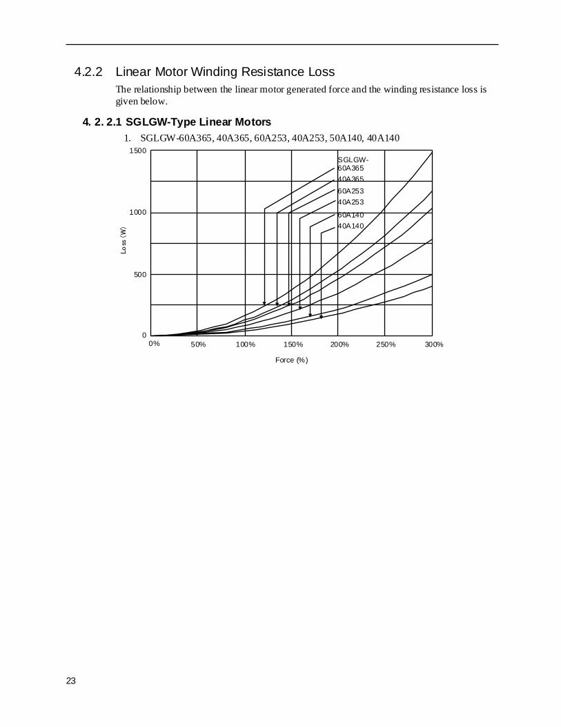
4.2.2 Linear Motor Winding Resistance LossThe relationship between the linear motor generated force and the winding resistance loss is given below.
4. 2. 2.1 SGLGW-Type Linear Motors1. SGLGW-60A365, 40A365, 60A253, 40A253, 50A140, 40A140
Force (%)
0% 50%
1500
Loss
(W
)
100% 150% 200% 250% 300%
1000
500
0
40A25360A25340A36560A365SGLGW-
60A14040A140

4.2.2 Linear Motor Winding Resistance Loss
24
4. 2. 2.2 SGLTW-Type Linear Motors1. SGLTW-35A460A, 35A320A, 35A170A, 20A460A, 20A320A, 20A170A
2. SGLTW-80A600, 80A400, 40A600, 40A400
300%0
500
1000
1500
2000
2500
3000
0% 100% 200%
3500
4000
Force (%)
Loss
(W)
20A460A35A170A35A320A35A460A
SGLTW-
20A170A
20A320A
300%0
1000
2000
3000
4000
5000
6000
0% 100% 200%
Force (%)
Loss
(W)
7000
8000
40A40040A60080A40080A600
SGLTW-
25
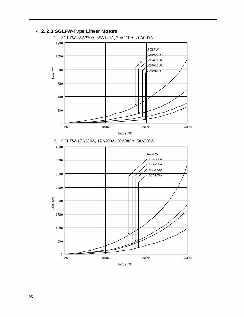
4. 2. 2.3 SGLFW-Type Linear Motors1. SGLFW-35A230A, 35A120A, 20A120A, 20A090A
2. SGLFW-1ZA380A, 1ZA200A, 50A380A, 50A200A
20A090A
20A120A35A120A35A230A
SGLFW-
0
200
400
600
800
1000
1200
0% 100% 200% 300%
Force (%)
Loss
(W
)
0
500
1000
1500
2000
2500
3000
0% 100% 200% 300%
3500
4000
50A200A
50A380A
1ZA200A1ZA380A
SGLFW-
Force (%)
Loss
(W)
4.2.3 Energy Absorbable by Servo Amplifier
26
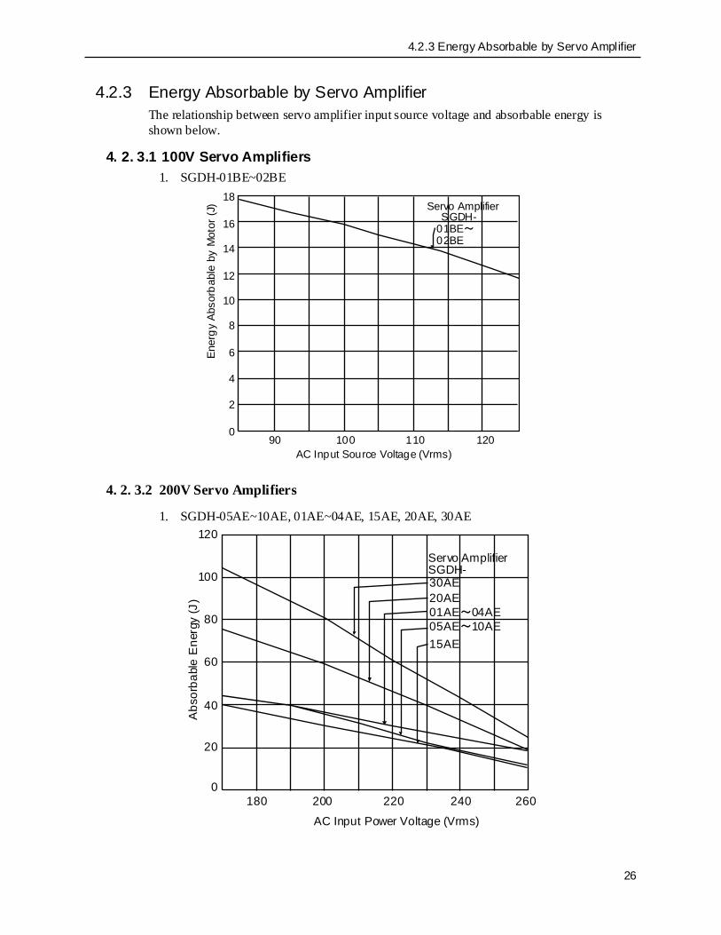
4.2.3 Energy Absorbable by Servo AmplifierThe relationship between servo amplifier input source voltage and absorbable energy is shown below.
4. 2. 3.1 100V Servo Amplifiers1. SGDH-01BE~02BE
4. 2. 3.2 200V Servo Amplifiers
1. SGDH-05AE~10AE, 01AE~04AE, 15AE, 20AE, 30AE
0
6
8
12
18
14
100 110 120
4
2
10
16
90
SGDH-01BE~02BE
AC Input Source Voltage (Vrms)
Ener
gy A
bsor
babl
e by
Mot
or (J
) Servo Amplifier
0200 220 240
20
180 260
40
60
80
100
120
15AE05AE~10AE01AE~04AE20AE30AE
Servo AmplifierSGDH-
AC Input Power Voltage (Vrms)
Abs
orba
ble
Ene
rgy
(J)

27
2. SGDH-50AE, 75AE
0200 220 240
100
180 260
200
300
400
500
600
700
75AE
50AE
AC Input Source Voltage (Vrms)
Servo AmplifierSGDH-
Abs
orba
ble
Ene
rgy
(J)

5.2.1 User Parameter List
28
5. Differences Between Rotary Motors and Linear Motors
5.1 Terms/Units
5.2 User Parameters
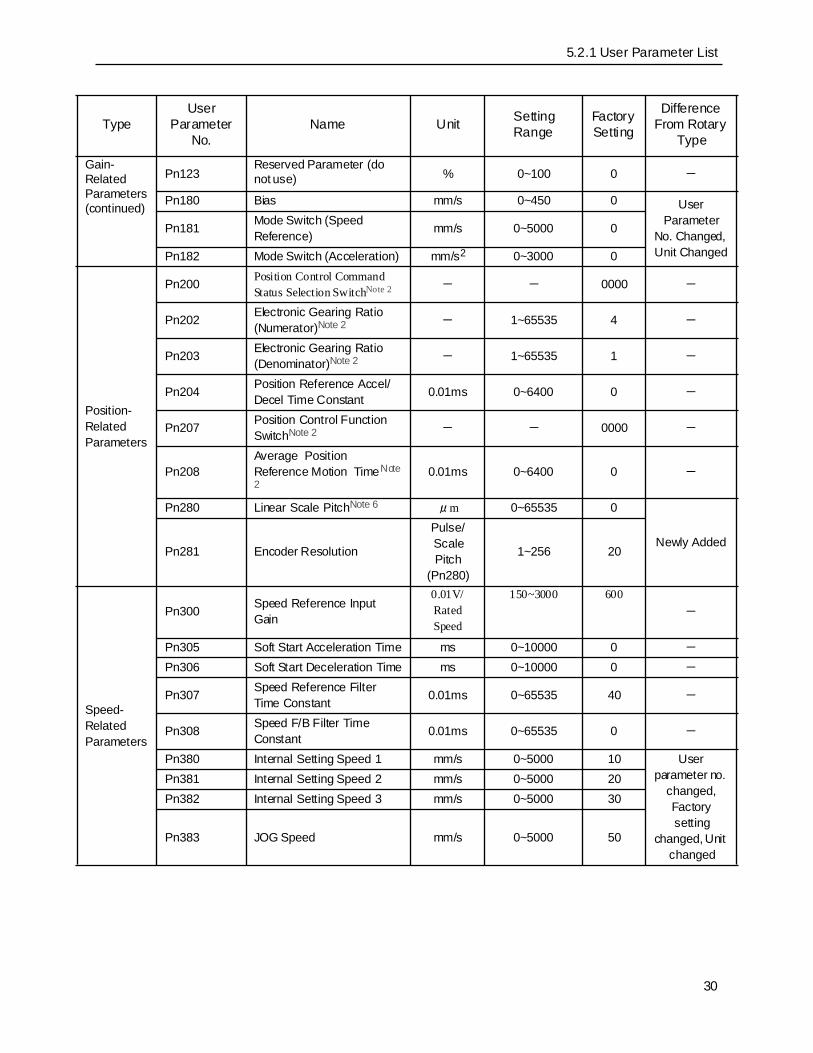
5.2.1 User Parameter ListThe user Parameter List is shown below.
Rotary-Type Linear-Type
Name Unit Name Unit
Torque N•m Force NSpeed r/min Speed mm/sAcceleration r/s2 Acceleration mm/s2
Moment of Inertia Kg/m2 Mass Kg
Linear Scale Pitch µm
Encoder Resolution P/r Encoder Resolution Pulse/Scale Pitch
TypeUser
Parameter No.
Name Unit Setting Range
Factory Setting
Difference From Rotary
Type
Function Selection Parameters
Pn000 Basic Function Selection Switch Note 1 - - 0000 -
Pn001 Function Selection Application Switch1 Note 2 - - 0000 -
Pn002 Function Selection Application Switch2 Note 2 - - 0000 -
Pn003 Function Selection Application Switch 3 - - 0002 -
Pn004Reserved Parameters (do not use)
- - 0000 -
Pn005 - - 0000 -
Pn006 - - 0100 -
Pn080 Function Selection Application Switch 6 Note 2 - - 0000 Newly Added

29
Gain-Related Parameters
Pn100 Speed Loop Gain Hz 1~2000 40 -
Pn101 Speed Loop Integral Time Constant 0.01ms 15~51200 2000 -
Pn102 Position Loop Gain 1/s 1~2000 40 -
Pn103 Mass Ratio % 0~10000 0 Name Changed
Pn104 2nd Speed Loop Gain Hz 1~2000 40 -
Pn105 2nd Speed Loop Integral Time Constant 0.01ms 15~51200 2000 -
Pn106 2nd Position Loop Gain 1/s 1~2000 40 -
Pn108 Bias Acceleration Width Command Unit 0~250 7 -
Pn109 Feed Forward % 0~100 0 -
Pn10A Feed Forward Filter Time Constant
0.01ms 0~6400 0 -
Pn10B Gain-Related Application SwitchNote 2 - - 0000 -
Pn10C Mode Switch (Force Reference)
% 0~800 200 Name Changed
Pn10F Mode Switch (Deviation Pulse)
Command Unit 0~10000 0 -
Pn110 Online Autotuning-related
SwitchN ote 2 - - 0010 -
Pn111 Speed Feedback CompensationNote 1 % 1~500 100 -
Pn112
Reserved Parameters (do not use)
% 0~1000 100 -
Pn113 - 0~1000 1000 -
Pn114 - 0~1000 200 -
Pn115 - 0~65535 32 -
Pn116 - 0~65535 16 -
Pn117 % 20~100 100 -
Pn118 % 50~100 100 -
Pn119 1/s 1~2000 50 -
Pn11A 0.1% 1~2000 1000 -
Pn11B Hz 1~150 50 -
Pn11C Hz 1~150 70 -
Pn11D % 0~150 100 -
Pn11E % 0~150 100 -
Pn11F ms 0~2000 0 -
Pn120 0.01ms 0~51200 0 -
Pn121 Hz 10~250 50 -
Pn122 Hz 0~250 0 -
TypeUser
Parameter No.
Name Unit Setting Range
Factory Setting
Difference From Rotary
Type
5.2.1 User Parameter List
30
Gain-Related Parameters
(continued)
Pn123Reserved Parameter (do not use) % 0~100 0 -
Pn180 Bias mm/s 0~450 0 User Parameter
No. Changed, Unit Changed
Pn181 Mode Switch (Speed Reference) mm/s 0~5000 0
Pn182 Mode Switch (Acceleration) mm/s2 0~3000 0
Position-Related Parameters
Pn200 Position Control Command Status Selection SwitchNote 2 - - 0000 -
Pn202 Electronic Gearing Ratio (Numerator)Note 2 - 1~65535 4 -
Pn203 Electronic Gearing Ratio (Denominator)Note 2 - 1~65535 1 -
Pn204 Position Reference Accel/Decel Time Constant 0.01ms 0~6400 0 -
Pn207 Position Control Function SwitchNote 2 - - 0000 -
Pn208Average Position Reference Motion TimeNote 2
0.01ms 0~6400 0 -
Pn280 Linear Scale PitchNote 6 μm 0~65535 0
Newly AddedPn281 Encoder Resolution
Pulse/Scale Pitch
(Pn280)
1~256 20
Speed-Related Parameters
Pn300 Speed Reference Input Gain
0.01V/Rated Speed
150~3000 600-
Pn305 Soft Start Acceleration Time ms 0~10000 0 -
Pn306 Soft Start Deceleration Time ms 0~10000 0 -
Pn307 Speed Reference Filter Time Constant 0.01ms 0~65535 40 -
Pn308 Speed F/B Filter Time Constant 0.01ms 0~65535 0 -
Pn380 Internal Setting Speed 1 mm/s 0~5000 10 User parameter no.
changed, Factory setting
changed, Unit changed
Pn381 Internal Setting Speed 2 mm/s 0~5000 20Pn382 Internal Setting Speed 3 mm/s 0~5000 30
Pn383 JOG Speed mm/s 0~5000 50
TypeUser
Parameter No.
Name Unit Setting Range
Factory Setting
Difference From Rotary
Type

31
Force-Related Parameters
Pn400 Force Reference Input Gain0.1V/
Continuous Force
10~100 30 Name Changed
Pn401 Force Reference Filter Time Constant 0.01ms 0~65535 100 Name
Changed
Pn404 Forward External Force Limit % 0~800 100 Name
Changed
Pn405 Reverse External Force Limit % 0~800 100 Name
Changed
Pn406 Emergency Stop Force % 0~800 800 Name Changed
Pn408 Force-Related Function Switch - - 0000 Name
ChangedPn409 Notch Filter Frequency Hz 50~2000 2000 -
Pn480 Speed Limit During force Control mm/s 0~5000 5000
User parameter no.
changed, Factory setting
changed, Unit changed
Pn483 Forward Force LimitNote 7 % 0~800 30
User Parameter
No. Changed, Factory Setting
ChangedPn484 Reverse Force LimitNote 7 % 0~800 30
TypeUser
Parameter No.
Name Unit Setting Range
Factory Setting
Difference From Rotary
Type

5.2.1 User Parameter List
32
Sequence-Related Parameters
Pn500 Positioning Completion Width
Command Unit 0~250 7 -
Pn504 NEAR Signal Width Command Unit 1~250 7 -
Pn505 Overflow Level256
Command Units
1~32767 1024 -
Pn506 Brake Command-Servo OFF Lag Time 10ms 0~50 0 -
Pn508 Servo OFF-Brake Command Wait Time 10ms 10~100 50 -
Pn509 Momentary Stop Hold Time ms 20~1000 20 -
Pn50A Input Signal Selection 1Note 2 - - 2100 -
Pn50B Input Signal Selection 2Note 2 - - 6543 -
Pn50C Input Signal Selection 3Note 2 - - 8888 -
Pn50D Input Signal Selection 4Note 2 - - 8888 -
Pn50E Output Signal Selection 1Note 2 - - 3211 -
Sequence-Related Parameters(continued)
Pn50F Output Signal Selection 2Note 2 - - 0000 -
Pn510 Output Signal Selection 3Note 2 - - 0000 -
Pn511 Reserved Parameters (do not use)
- - 8888 -
Pn512 Output Signal Inversion SettingNote 2 - - 0000 -
Pn580 Zero Clamp Level mm/s 0~5000 10
User Parameter
No. Changed, Unit Changed
Pn581 Zero Speed Level mm/s 1~5000 20
Pn582 Speed Coincidence Signal Output Band mm/s 0~100 10
Pn583 Brake Command Output Speed Level mm/s 0~5000 100
Other Parameters
Pn600 Regenerative Resistor CapacityNote 3 W
0~by device typeNote 5
0 -
Pn601 Reserved Parameters (do not use) -
0~by device typeNote 5
0 -
TypeUser
Parameter No.
Name Unit Setting Range
Factory Setting
Difference From Rotary
Type

33
Note 1 The settings in user parameter Pn111 are enabled when user parameter Pn110.1 is “0”.Note 2 When this user parameter is changed, it is necessary to turn the main and control power
OFF and ON again in order to enable the function. However, Pn110.1 and Pn110.2 are enabled online.
Note 3 This is normally set to “0”. Set to the capacity (W) of the regenerative resistor if an external regenerative resistor is installed.
Note 4 The set value is ignored.Note 5 The upper limit is the maximum output capacity (W) of the applied servo amplifier.Note 6 The initial value is set to “0”. Therefore, alarm A.80 will be output when the power is first
turned ON. The alarm will not be output if this user parameter is set to the correct value and the power turned ON again.
Note 7 The factory setting is set small to prevent danger in motor setup. Raise the force to the amount used after setup is finished.

5.2.2 Switch List
34
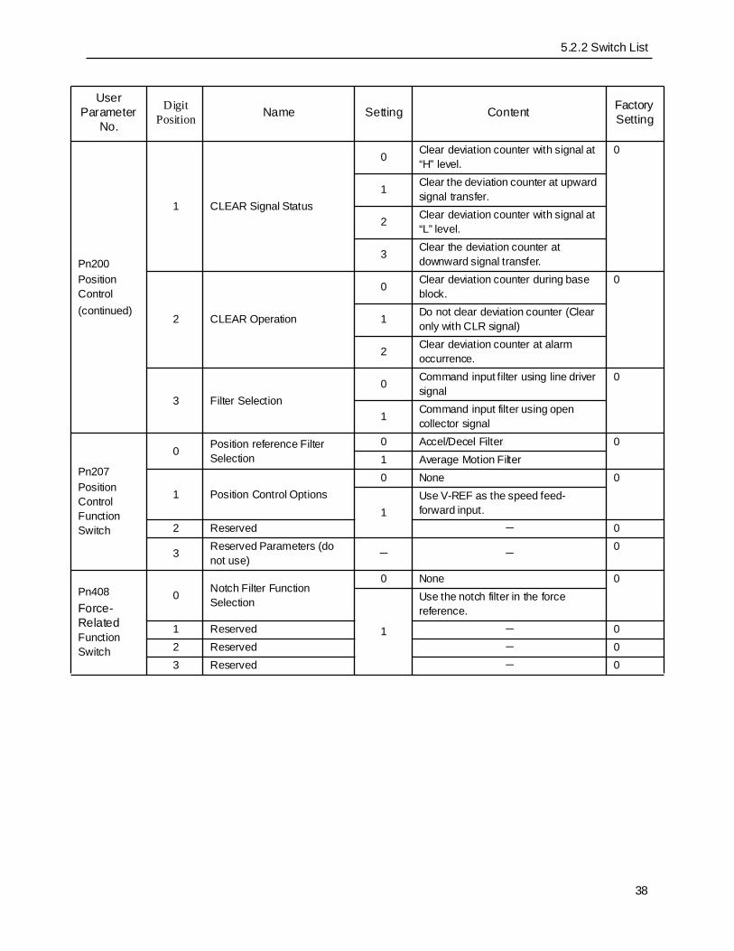
5.2.2 Switch ListThe switch List is shown below.
User Parameter
No.
Digit Position Name Setting Content Factory
Setting
Pn000Basic Function Selection
0 Motion Direction Selection0 Forward
01 Reverse
1 Control Format Selection
0 Speed Control (analog reference)
0
1 Position Control (pulse queue reference)
2 Force Control (analog reference)
3 Internal Setting Speed Control (contact reference)
4Internal Setting Speed Control (contact Reference Speed Control (analog reference)
5Internal Setting Speed Control (contact reference) Position Control (pulse queue reference)
6Internal Setting Speed Control (contact reference)´ Force Control (analog reference)
7Position Control (pulse queue reference) Speed Control (analog reference)
8Position Control (pulse queue reference) Force Control (analog reference)
9 Force Control (analog reference) Speed Control (analog reference)
40090A Speed Control (analog reference) Zero Clamp
B Position Control (pulse queue reference) Position Control (inhibit)
2 Axis Address 0~F Sets servo amplifier axis address. 0
3Rotary/Linear Actuation Selection (with encoder disconnected)
0 Actuate as rotary.0
1 Actuate as linear.

35
Pn001Application Function Selection
0 Stop Method at Servo OFF or Alarm Occurrence
0 Stop motor by dynamic braking (DB).
01 Stop motor by DB, the release D.
2 Do not use DB, let motor coast to stop.
1 Stop Method at Overtravel (OT)
0 Stop by DB or coasting (same stop method as in Pn001.0)
01
Assume the force set in Pn406 to be the maximum value, decelerate the motor to stop, the go to a servo lock state.
2
Assume the force set in Pn406 to be the maximum value, decelerate the motor to stop, the go to a free-run state.
2 AC/DC Power Input Selection
0Not DC Power Input-Compatible: Input AC power from terminals L1, L2, and (L3).
0
1DC Power Input-Compatible: Input DC power from the (+)1– (–) power inputs.
3 Warning CodeOutput Selection
0 AL01, AL02, and AL03 output warning codes only.
01
AL01, AL02, and AL03 output both alarm codes and warning codes. However, the ALM signal output stays ON (normal) during warning output.
Pn002Application Function Selection
0 Speed/Position Control Option (T-REF assignment)
0 None
0
1 Use T-REF after inputting external force limit.
2 Use T-REF after inputting force feed forward.
3Use the T-REF terminal as the external force limit input when P-CL and N-CL are “enabled”.
1 Force Control Option (V-REF assignment)
0 None0
1 Use V-REF after inputting external speed limit.
2 Reserved Parameters (do not use)
- - 03 - - 0
User Parameter
No.
Digit Position Name Setting Content Factory
Setting

5.2.2 Switch List
36
Pn003Application Function Selection
01
Analog Monitor 1 Force Reference Monitor Analog Monitor 2 Speed Reference Monitor
0 Monitor Motion Speed: 1V/1000mm/s
20
1 Speed Reference: 1V/1000mm/s2 Force Reference:1V/100%
3 Position Deviation: 0.05V/1 Command Unit
4 Position Deviation: 0.05V/100 Command Unit
5 Command Pulse Frequency [mm/s conversion]:1V/1000mm/s
6 Motor Run Speed×4: 1V/250mm/s7 Motor Run Speed×8: 1V/125mm/s8
Reserved Parameter(do not use)
940090A
BCDEF
2 Reserved - - 03 Reserved - - 0
Pn080 Machine Selection Applications
0 Hall Sensor SelectionNote3 0 Yes 01 None 0
1 Motor Phase Order Selection
0 A-phase progression, U, V, W-phase order 0
1 B-phase progression, U, V, W-phase order 0
2 Reserved - - 03 Reserved - - 0
User Parameter
No.
Digit Position Name Setting Content Factory
Setting

37
Pn10B Gain-Related Applications
0 Mode Switch Selection
0 Takes internal force reference as a condition (Level Setting: Pn10C)
0
1 Takes speed reference as a condition (Level Setting: Pn10D)
2 Takes acceleration as a condition (Level Setting: Pn10E)
3 Takes deviation pulse as a condition (Level Setting: Pn10F)
4 No mode switch function
1 Speed Loop Control Method0 PI Control
01 IP Control
2 Reserved 0 - 0
3 Reserved Parameter (do not use) 0~2 - 0
Pn110Autotuning
0 Online Autotuning Method0 Timing at initial run only.
01 Always tune.2 No autotuning.
1Speed Feedback Compensation Function Selection
0 Yes1
1 None
2Viscous Friction Compensation Function Selection
0 Friction Compensation: None01 Friction Compensation: Small
2 Friction Compensation: Large
3 Reserved Parameters (do not use) 0~3 - 0
Pn200Position Control
0 Command Pulse Status
0 Symbol+Pulse, Positive Logic
0
1 CW+CCW, positive logic
2 A-phase + B-phase (1×), positive logic
3 A-phase + B-phase (2×), positive logic
4 A-phase + B-phase (4×), positive logic
5 Symbol+Pulse, Negative Logic6 CW+CCW, negative logic
7 A-phase + B-phase (1×), negative logic
8 A-phase + B-phase (2×), negative logic
9 A-phase + B-phase (4×), negative logic
User Parameter
No.
Digit Position Name Setting Content Factory
Setting
5.2.2 Switch List
38
Pn200Position Control(continued)
1 CLEAR Signal Status
0 Clear deviation counter with signal at “H” level.
0
1 Clear the deviation counter at upward signal transfer.
2 Clear deviation counter with signal at “L” level.
3 Clear the deviation counter at downward signal transfer.
2 CLEAR Operation
0 Clear deviation counter during base block.
0
1 Do not clear deviation counter (Clear only with CLR signal)
2 Clear deviation counter at alarm occurrence.
3 Filter Selection0 Command input filter using line driver
signal0
1 Command input filter using open collector signal
Pn207Position Control Function Switch
0 Position reference Filter Selection
0 Accel/Decel Filter 01 Average Motion Filter
1 Position Control Options0 None 0
1Use V-REF as the speed feed-forward input.
2 Reserved - 0
3 Reserved Parameters (do not use) - -
0
Pn408Force-Related Function Switch
0 Notch Filter Function Selection
0 None 0
1
Use the notch filter in the force reference.
1 Reserved - 02 Reserved - 03 Reserved - 0
User Parameter
No.
Digit Position Name Setting Content Factory
Setting

39
5.2.3 Input Signal Selection ListThe input signal selection list is shown below.
User Parameter
No.
Digit Position Name Settin
g Content Factory
Setting
Pn50A
0 Input Signal Assignment Mode
0
Set the input signal assignment used in the sequence the same as the SGDB servo amplifier.Note1,Note2,Note3 0
1 The above input signal assignments can be freely set.
1 /S-ON Signal Mapping(Servo ON at “L”)
0 Input from SI0 (CN1-40) input terminal Note3
0: SI0
1 Input from SI1 (CN1-41) input terminal2 Input from SI2 (CN1-42) input terminal
3 Input from SI3 (CN1-43) input terminal Note1
4 Input from SI4 (CN1-44) input terminal5 Input from SI5 (CN1-45) input terminal6 Input from SI6 (CN1-46) input terminal7 Signal fixed at “enabled”8 Signal fixed at “disabled”
9 Inverted signal input from SI0 (CN1-40) input terminal
A Inverted signal input from SI1 (CN1-41) input terminal
B Inverted signal input from SI2 (CN1-42) input terminal Note1
C Inverted signal input from SI3 (CN1-43) input terminal
D Inverted signal input from SI4 (CN1-44) input terminal
E Inverted signal input from SI5 (CN1-45) input terminal
F Inverted signal input from SI6 (CN1-46) input terminal
2 /P-CON Signal Mapping (P control at “L”) 0~F As above 1: SI1
3 P-OT Signal Mapping (overtravel at “H”) 0~F As above 2: SI2

5.2.3 Input Signal Selection List
40
Note 1 In the SGDB servo amplifier function interchange mode where Pn50A.0=0, only settings Pn50A.1=7, Pn50A.3=8, and Pn50B.0=8 are possible.
Note 2 When Pn50A.1=1, the zero clamp function by /P-CON signal cannot be used.Note 3 If Pn080.0 is set to 1 (no polarity sensor), set Pn50A.0=1, and set Pn50D.3 to any value
desired. The motor cannot be driven unless polarity detection is performed.
Pn50B
0 N-OT Signal Mapping (overtravel at “H”) 0~F As above 3: SI3
1 /ALM-RST Signal Mapping (alarm reset at “L”) 0~F As above 4: SI4
2 /P-CL Signal Mapping (force limit at “L”) 0~F As above 5: SI5
3 /N-CL Signal Mapping (force limit at “L”) 0~F As above 6: SI6
Pn50C
0/SPD-D Signal Mapping (internal setting speed selection)
0~F As above 8: Disabled
1/SPD-A Signal Mapping (internal setting speed selection)
0~F As above 8: Disabled
2/SPD-B Signal Mapping (internal setting speed selection)
0~F As above 8: Disabled
3 /C-SEL Signal Mapping (control mode switching) 0~F As above 8:
Disabled
Pn50D
0 /ZCLAMP Signal Mapping (zero clamp) 0~F As above 8:
Disabled
1 /INHIBIT Signal Mapping (command pulse inhibit) 0~F As above 8:
Disabled
2 /G-SEL Signal Mapping (gain switching) 0~F As above 8:
Disabled
3 /P-DET Signal Mapping (polarity detection)Note3 0~F As above 8:
Disabled
User Parameter
No.
Digit Position Name Settin
g Content Factory
Setting

41
5.2.4 Output Signal Selection ListThe output signal selection list is shown below.N ote1, N ote2
Note 1 If multiple signals are assigned to the same output circuit, the output is done by OR logic.Note 2 Undetected signals are assumed to be OFF according to the control mode. For example, the
/COIN signal is assumed to be OFF in the speed control mode.Note 3 /WARN Signal Types: Overload, Regent Overload, Option Warning
User Parameter
No.
Digit Position Name Setting Content Factory
Setting
Pn50E
0/COIN Signal Mapping (internal setting speed selection)
0 Not used
1: SO1
1 SO1 (CN1-25, 26) output from output terminal
2 SO2 (CN1-27, 28) output from output terminal
3 SO3 (CN1-29, 30) output from output terminal
1 /V-CMP Signal Mapping 0~3 As above 1: SO12 /TGON Signal Mapping 0~3 As above 2: SO23 /S-RDY Signal Mapping 0~3 As above 3: SO3
Pn50F
0 /CLT Signal Mapping 0~3 As above 0: Unused1 /VLT Signal Mapping 0~3 As above 0: Unused2 /BK Signal Mapping 0~3 As above 0: Unused
3 /WARN Signal MappingNote 3 0~3 As above 0: Unused
Pn510
0 /NEAR Signal Mapping 0~3 As above 0: Unused1 Reserved Parameter 0~3 As above 0: Unused2 Reserved 0 - 03 Reserved 0 - 0
Pn512
0 SO1 (CN1-25, 26) Terminal Output Signal Inversion
0 No output signal inversion.0
1 Output signal inversion.
1 SO2 (CN1-27, 28) Terminal Output Signal Inversion
0 No output signal inversion.0
1 Output signal inversion.
2 SO3 (CN1-29, 30) Terminal Output Signal Inversion
0 No output signal inversion.0
1 Output signal inversion.3 Reserved - - 0

5.2.5 Auxiliary Function List
42
5.2.5 Auxiliary Function ListThe auxiliary function list is shown below.
User Parameter No. Function
Fn000 Displays alarm traceback dataFn001 Sets rigidity in online autotuningFn002 JOG Mode RunFn003 Origin Search ModeFn004 (reserved parameter)Fn005 User Parameter Setting InitializationFn006 Alarm Traceback Data Clear
Fn007 Write Results of Online Autotuning Operation to Mass Ratio Data EEPROM
Fn008 Absolute Encoder Multi-Turn Setting (setup operation) and Encoder Alarm Reset
Fn009 Automatic Adjustment of Analog (speed , force) Reference OffsetsFn00A Manual Adjustment of Speed Reference OffsetFn00B Manual Adjustment of Force Reference OffsetFn00C Manual Zero Adjustment of Analog Monitor OutputFn00D Manual Gain Adjustment of Analog Monitor OutputFn00E Automatic Adjustment of Motor Current Detection Signal OffsetFn00F Manual Adjustment of Motor Current Detection Signal OffsetFn010 Password Setting (user parameter overwrite prohibition processing)Fn011 Verification of Motor TypeFn012 Display Servo Amplifier Software Version
Fn013 Change Multi-Turn Limit Setting at ”Multi-Turn Limit Non-Coincidence (A.CC)” Alarm Occurrence
Fn014 Clear Result of Option Unit Detection

43
5.2.6 Monitor Mode ListThe monitor mode list shown below.
User Parameter No. Display Content Unit Note
Un000 Actual Motor Motion Speed mm/s -
Un001 Speed Reference Input mm/s -
Un002 Internal Force Reference % Percentage of rated forceUn003 Electrical Angle 1 pulse Number of pulses from origin
Un004 Electrical Angle 2 deg Degrees from origin (electrical angle)
Un005 Input Signal Monitor - -
Un006 Output Signal Monitor - -
Un007 Speed of Input Reference Pulse mm/s -
Un008 Deviation Counter Value Command Unit Position Deviation
Un009 Cumulative Load Rate %
Value at 100% rated force Displays the effective force for a 10sec. cycle
Un00A Rated Load Factor %
Value at 100% processable regen power Displays the regen consumption power for a 10sec period
Un00B DB Resistor Consumption Power %
Value at 100% processable power during dynamic brake operation Displays DB consumption current for a 10sec cycle
Un00C Input Reference Pulse Counter - Displayed in hexadecimalsUn00D Feedback Pulse Counter - Displayed in hexadecimals
Un104 Number of S-PG Communication Errors -
Displayed in decimals(common to rotary and linear)

5.2.6 Monitor Mode List
44
5.3 Alarm Display ListThe ON/OFF relationships for “Alarm Displays” and “Alarm Outputs” are shown in the table below.
Alarm Display and Output List
Alarm Display
Alarm Code Output Servo Alarm (ALM) Output
Alarm Name Alarm Content
Alarm Object
ALO1 ALO2 ALO3 Rotary Linear
A.02
× × × ×
Parameter CorruptionNote 2
Error in servo amplifier EEPROM data
A.03 Main Circuit Sensor Error
Error in individual detection data for the power circuit
A.04 Parameter Setting ErrorNote 2
A user parameter value exceeding the setting range was set
A.04 User Parameter SettingNote 2 Error
• A value outside the setting range was previously set or saved in a user parameter.
• Pn080.0=1 even though Hall sensor is attached, or pn080.0=0 even though no Hall sensor is attached.
A.05 Combination ErrorImproper combination of motor and servo amplifier capacity
A.08 Linear Scale Pitch Setting Error
Value of Pn280 is at factory setting.
A.10 × × × Overcurrent or heat sink overheatNote 2
Heating current is flowed to IGBT. or servo amplifier heat sink has overheated
A.30
× ×
Regent Error
• Regenerative Resistor Disconnection
• Regenerative transistor failure
A.32 Regent OverloadRegeneration energy has exceeded the capacity of the regenerative resistor
A.33 Main Power Connection Error
(DC power fed in AC power input mode)(AC power fed in DC power input mode)
A.40× × ×
OvervoltageNote 4 Main circuit DC voltage is too high
A.41 UndervoltageNote 4 Main circuit DC voltage has dropped

45
A.51 × ×
Overspeed Motor speed is too high
A.51 Overspeed Encoder output frequency has exceeded 15Mpps
A.71
×
Overload(momentary maximum load)
Operated for several to sever lens of seconds at torque or force greatly exceeding the rating
A.72 Overload(continuous maximum load)
Continuous operation at a torque or force exceeding the rating
A.73 DB Overload
The kinetic energy in DB (dynamic braking) operation exceeds the capacity of the DB resistor
A.74 ×
Surge Resistor Overload
Main power ON/OFF frequently repeated
A.7A Heat Sink OverheatNote 1
Servo amplifier heat sink has overheated
A.81
× × × ×
Encoder Backup Alarm Note 2
Encoder power is completely down, and position data is cleared
A.82 Encoder Sum Check Alarm Note 2
Error in encoder memory sum check results
A.83 Encoder Battery Alarm
Drop in absolute encoder backup battery
A.84 Encoder Absolute AlarmNote 2
Error in absolute data received
A.85 Encoder OverspeedThe encoder operated at excessive speed when power was fed
A.86 Encoder Overheat Internal temperature of encoder is too high
A.b1 Speed Reference A/D Error
Error in speed reference input A/D converter
A.b2 Torque/Force Reference A/D Error
Error in torque/force reference A/D converter
A.Bf System AlarmNote 2
Alarm Display
Alarm Code Output Servo Alarm (ALM) Output
Alarm Name Alarm Content
Alarm Object
ALO1 ALO2 ALO3 Rotary Linear

5.2.6 Monitor Mode List
46
Note 1 : Output transistor ON ×: Output transistor OFF (alarm state)Note 2 A.08 will always appear at the very first powering-up of the unit. The alarm will go out if
the customer inputs the correct values and cycles the power. Note 3 Displayed in 30W~100W.Note 4 Cannot be released by the alarm reset (/ALM-RST) signal. Release the alarm by removing
the cause of the alarm then turning the power OFF.Note 5 Installed in version upgrade (SGDM- DA) only.Note 6 Servo amplifiers with capacities of 6kW or greater will display a “Main Circuit Voltage
Error Detection” alarm in “A40”. This means that either an overvoltage or undervoltage error has occurred.
For details on these alarms, see 9.2 “Error Diagnosis and Corrective Measures” in the “Σ-II Series SGM H/SGDH User's Manual, Design and Maintenance (SI-S800-32.2).
A.C1
× ×
Runaway Prevention Detection Runaway linear motor
A.C5Linear Motor Polarity Position Error Detection
Detection of linear motor polarity position failed
A.C8Encoder CLEAR Error Multi-Turn Limit Setting ErrorNote 2
The multi-turn value of the absolute encoder has been cleared, or the settings are incorrect
A.C9Encoder Communication ErrorNote 2
Communication not possible between encoder and servo amplifier
A.CA Encoder Parameter ErrorNote 2
Encoder parameters are corrupted
A.Cb Encoder Echo-back ErrorNote 2
Content of the encoder communication is erroneous
A.CC Multi-Turn Limit Non-CoincidenceNote 3
Multi-turn limit data between encoder and servo amplifier do not match
A.d0 × × Excessive Position Deviation
Position deviation pulse exceeds the value set in user parameter (Pn505)
A.F1 × × × Power Line Phase Loss
One phase is missing within the 3-phase main circuit power
CPF00
Undefined Digital Operator Communication Error
Communication not possible between the digital operator (JUSP-OP02A-2) and the servo amplifier
CPF01
A.- - × × × Not an error display Shows a normal operation state
Alarm Display
Alarm Code Output Servo Alarm (ALM) Output
Alarm Name Alarm Content
Alarm Object
ALO1 ALO2 ALO3 Rotary Linear
Supp.

47
5.4 Warning Display ListThe ON/OFF relationships for “Warning Displays” and “Warning Code Outputs” are shown in the table below.
Warning Display and Output List
Note 1 : Output transistor ON ×: Output transistor OFF (warning state)
Warning Display
Warning Code OutputWarning Name Warning Content
Warning Object
ALO1 ALO2 ALO3 Rotary Linear
A.91 × × OverloadWarning displayed before reaching an overload (A.71 or A.72) alarm. An alarm may result if operation is continued as is.
A.92 × × Regent OverloadWarning displayed before reaching a regen overload (A.32) alarm. an alarm may result if operation is continued as is.
A.93 × × Battery WarningBattery warning message displayed when an absolute encoder is used as an absolute encoder.

6.1.1 SGLGW-Type Linear Motor
48
6. Ratings and Specifications6.1 Linear Motors
6.1.1 SGLGW-Type Linear Motor
6. 1. 1.1 Standard Linear Motor Ratings/Specifications
Ratings/Specifications for SGLGW-Type Standard Linear Motor
* These items and force/speed characteristics are the values at a motor winding temperature of 100°C° during operation in combination with a servo amplifier. The others are at 20°C.
Note: “Continuous Force” shows the continuous allowable force when the following aluminum boards (heat sinks) are attached as a cooling means at an ambient temperature of 20°C.
• Time Rating: Continuous • Insulation Resist Voltage: AC1500V 1min.
• Insulation Resistance: DC500V, 10MΩ or higher
• Protection Methods: Self-cooling, air cooling
• Ambient Temperature: 0~40°C • Ambient Humidity: 20~80% (no condensation)
• Excitation Type: Permanent magnet
Linear Motor Model SGLGW- 40A140A 40A253A 40A365A 60A140A 60A253A 60A365A
Continuous Output* W 94 186 280 146 294 440Continuous Force* N 47 93 140 73 147 220Continuous Current* Arms 0.8 1.6 2.4 1.2 2.3 3.5
Peak Force* N 140 280 420 220 440 660Peak Current* Arms 2.4 4.9 7.3 3.5 7.0 10.5Moving Coil Mass kg 0.39 0.65 0.91 0.47 0.8 1.13Force Constant N/Arms 61.5 61.5 61.5 66.6 66.6 66.6BEMF Constant V/(m/s) 20.5 20.5 20.5 22.2 22.2 22.2Electrical Time Constant ms 0.4 0.3 0.3 0.4 0.4 0.4
Mechanical Time Constant ms 5.4 4.9 4.7 3.3 3.0 2.9
Allowable Winding Temperature
130 (B type)
130 (B type)
130 (B type)
130 (B type)
130 (B type)
130 (B type)
Applied Device Types Heat Sink Size
40A140A125×254×13 mm40A253A
60A140A

49
6. 1. 1.2 Force–Speed CharacteristicsThe force–speed characteristics of the SGLGW linear motors are shown below.
40A365A305×380×13 mm60A253A
60A365A
Applied Device Types Heat Sink Size
0
2.0
6.0
3.0
300 4501500 600
4.0
1.0
A
B
SGLGW-40A365A
5.0208V
0
2.0
6.0
3.0
4002000 600
4.0
1.0
A
B
SGLGW-60A253A
5.0208V
0
2.0
6.0
3.0
6003000 900
4.0
1.0
A
B
SGLGW-60A365A
5.0 208V
0
2.0
6.0
3.0
2001000 300
4.0
1.0
A
B
SGLGW-60A140A
5.0208V
0
2.0
6.0
3.0
200 3001000 400
4.0
1.0
A
B
SGLGW-40A253A
5.0208V
Force (N)
Speed(m/s)
Speed(m/s)
Force (N)
Speed(m/s)
Force (N)Force (N)
Speed(m/s)
Force (N)
Speed(m/s)
0
2.0
6.0
3.0
100 150500 200
4.0
1.0
A
B
SGLGW-40A140A
5.0208V
Force (N)
Speed(m/s)

6.1.1 SGLGW-Type Linear Motor
50
6. 1. 1.3 Dimensional Drawing of Motor (SGLGW–AA)
Motor Model
SGLGW-
Dim. L1
Dim. L2
Dim. L3
Dim. L4
Dim. L5
Dim. L6
Dim. H1
Units N1
Units N2
Mass(Kg)
Magnet Track Model
SGLGM-
40A140A 140 125 90 30 52.5 45 63 3 4 0.3940A40A253A 252.5 237.5 180 37.5 60 135 63 5 8 0.65
40A365A 365 350 315 30 52.5 270 63 8 14 0.9160A140A 140 125 90 30 52.5 45 83 3 4 0.47
60A60A253A 252.5 237.5 180 37.5 60 135 83 5 8 0.8060A365A 365 350 315 30 52.5 270 83 8 14 1.13
2 -Scr ew
#4- 40 UNC
(φ 7)
( φ 5.3)
500±
50
500±
50
16
L4
45
L1
L3
30
M ounting Ho le (both ends)
M 4Tap Dept h 6 mm
L2
1 U-Phase
2
3
4
Name
V-Phase
W- Phase
F G
Color
Red
White
Blue
Grn/Yel
Pin N o.1
2
3
4
5
6
7
8
9 Empty
Empty
Empty
Empty
0V (Source)
W-Phase
V- Phase
U- Phase
+5V (Source)
NamePin N o.
1 2 3 4
9 6
15
Motor Cont act orSpecif icat ions
Po le Sensor Co nne ct orSpecifications
Cap: 3507 80-1Socke t: 350570- 3 or 350689- 3
Counterpart Model Number
Pin: 350561-3 or 3 50690-3( No .1~3) 3 50654-1 3 50669-1( No .4)
Flag: 350779-1 AMP
S ocket Type Connector : 17JE-1 3090-02( D8C)Studds: 17L- 002C or 17L- 002C1
Counter part Mo del Numb er
Dai-Ichi De nko , Inc.
P in TypeConnecto r: 17JE-23090- 02 (D8C)
L5
45
L6
17
取付け穴
M4タップ 深さ6mm
NP
83
25.4
4.8
7 .2
5.4
15
0.5
14
180
Vu
360 54 00
Vv
Vw
Su
Sw
Sv
Electr ical Angle (°)
Inve
rse
Pow
er (
V)
When the moto r moves tn the d ir ectionindicated by the a rrow in the figure, therelationship between the po le senso routput signals Su, Sv, and Sw, and theinverse po wer of each mo tor phasebeco mes as shown in the f igure at right.
P ole Sensor Output Signal

51
6. 1. 1.4 Dimensional Drawing of Magnet Track (SGLGM–A)
Magnet Track Model
SGLGM-
Dim.L1
Dim.L2
Dim.H1
UnitsN
Mass(Kg)
40090A 90 45 62 2 0.840225A 225 180 62 5 2.040360A 360 315 62 8 3.140405A 405 360 62 9 3.540450A 450 405 62 10 3.960090A 90 45 82 2 1.060225A 225 180 82 5 2.660360A 360 315 82 8 4.160405A 405 360 82 9 4.660450A 450 405 82 10 5.1
X
X
7
7
45
45
L 2
φ10
φ5.
5
φ10
NP
x-x
-0.3-0.1
H1
12.7
25.4
5.4 5.4
M4 Tap De pth 4mmMounti ng Hole
L222.5
22.5
Mounting Hol e
W arning Level
L1 (1 unit)

6.1.1 SGLGW-Type Linear Motor
52
6. 1. 1.5 Structural Diagram of SGLGW
25.4
0.8
4.87.2
25.4
15
( 78/
98 )
0.8
5.4
1

53
6.1.2 SGLTW-Type Linear Motor
6. 1. 2.1 Standard Linear Motor Ratings/Specifications
Ratings/Specifications for SGLTW-Type Standard Linear Motor
• Time Rating: Continuous • Insulation Resist Voltage: AC1500V 1min.
• Insulation Resistance: DC500V, 10MΩ or higher
• Protection Method: Self-cooling
• Ambient Temperature: 0~40°C • Ambient Humidity: 20~80% (no condensation)
• Excitation Type: Permanent magnet
Linear Motor ModelsSGLTW-
20A 35A
170A 320A 460A 170A 320A 460A
Continuous Output* W 325 625 950 550 1100 1675
Continuous Force* N 130 250 380 220 440 670
Continuous Current* Arms 2.3 4.4 6.7 3.3 7.0 10.7
Peak Force * N 380 760 1140 660 1320 2000
Peak Current* Arms 7.7 15.4 23.2 12.1 24.2 36.7
Moving Coil Mass Kg 2.6 4.6 6.7 3.7 6.8 10.0
Force Constant* N/Arms 61.0 61.0 61.0 67.5 67.5 67.5
BEMF Constant* V/(m/s) 20.3 20.3 20.3 22.5 22.5 22.5
Electrical Time Constant* ms 5.9 5.9 5.9 6.9 6.8 7.0
Mechanical Time Constant*
ms 7.5 6.5 6.4 5.2 4.8 4.6
Allowable Winding Temperature
130
(B type)130
(B type)130
(B type)130
(B type)130
(B type)130
(B type)
Linear Motor ModelsSGLTW-
40A 80A
400A 600A 400A 600A
Cont. Output* W 1675 2500 2600 4000Cont. Force* N 670 1000 1300 2000

6.1.2 SGLTW-Type Linear Motor
54
* These items and force/speed characteristics, are the values at a motor winding temperature of 100°C during operation in combination with a servo amplifier. All other values apply to winding temperatures of 20°C.
Note: “Continuous Force” shows the continuous allowable value when the following aluminum plates (heat sinks) are attached as a cooling means at an ambient temperature of 20°C.
Cont. Current* Arms 10.8 16.1 19.3 29.7Peak Force* N 2000 3000 4000 6000Peak Current* Arms 37.0 55.5 67.8 101.8
Moving Coil Mass Kg 20.0 30.0 30.0 43.0
Force Constant* N/Arms 66.9 66.9 72.6 72.6
BEMF Constant* V/(m/s) 22.3 22.3 24.2 24.2
Electrical Time Constant* ms 17.8 16.5 19.3 16.6
Mechanical Time Constant*
ms 4.9 5.1 3.7 3.9
Allowable Winding Temperature
130 (B type)
130 (B type)
130 (B type)
130 (B type)
Applied Device Types Heat Sink Size
20A170A254×254×25(mm)
35A170A20A320A
400×500×40(mm)20A460A35A320A35A460A40A400A
609×762×50(mm)40A600A80A400A80A600A
Linear Motor ModelsSGLTW-
40A 80A
400A 600A 400A 600A

55
6. 1. 2.2 Force/Speed CharacteristicsThe force/speed characteristics of the SGLTW linear motors are shown below.
Speed(m/s)
SGLTW-20A170A
200 3001000 400
A B
0
6
2
4
3
1
5
Force (N)
208VSpeed(m/s )
Force (N)
SGLTW-20A320A
400 6002000 800
A B
0
6
2
4
3
1
5 208V
Speed(N)
Force (N)
SGLTW-20A460A
800 12004000 1600
A B
0
6
2
4
3
1
5208V
Speed(m/s)
Force (N)
SGLTW-35A170A
400 6002000 800
A B
0
6
2
4
3
1
5208V
Speed(m/s)
Force (N)
SGLTW-35A320A
800 12004000 1600
A B
0
6
2
4
3
1
5208V
Speed(m/s)
Force (N)
SGLTW-35A460A
1000 15005000 2000
B
0
6
2
4
3
1
5
A
208V

6.1.2 SGLTW-Type Linear Motor
56
6. 1. 2.3 Dimensional Drawing of Motor 1 (SGLTW– A )
Motor Model
SGLTW-
Dim. L1
Dim. L2
Dim.L3
Dim. H1
Dim. H2
Dim. H3
Dim. H4
Units N
Mass (Kg)
Magnet Track Model SGLTM-
20A170A 170 144 1670 55 40 27
8 2.620A20A320A 315 288 17 14 4.6
20A460A 460 432 18 20 6.735A170A 170 144 16
85 70 55 34.58 3.7
40A35A320A 315 288 17 14 6.835A460A 460 432 18 20 10
6.1.2.3

57
6. 1. 2.4 Dimensional Drawing of Motor 2 (SGLTW–AA)
Motor Model
SGLTW-
Dim. L1
Dim.L2
Dim.L3
Dim.H1
Dim.H2
Dim.H3
Dim.H4
Units N
Mass (Kg)
Magnet Track Model SGLTM-
40A400A 395 360 15103 83 63 39
14 2040A
40A600A 585 540 25 20 3080A400A 395 360 15
140 120 100 5714 30
80A80A600A 585 540 25 20 43

6.1.2 SGLTW-Type Linear Motor
58
6. 1. 2.5 Dimensional Drawing of Magnet Track (SGLTM–A)(Applicable only to North American Markets)
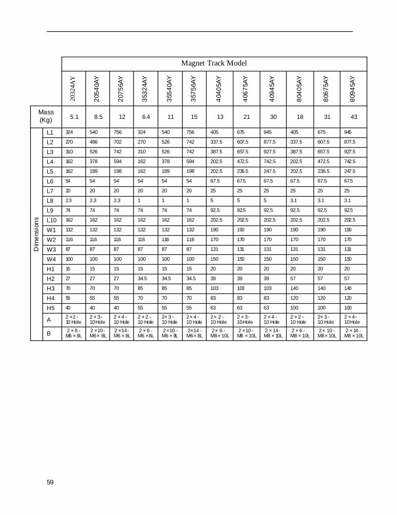
59
Magnet Track Model20
324A
Y
2054
0AY
2075
6AY
3532
4AY
3554
0AY
3575
6AY
4040
5AY
4067
5AY
4094
5AY
8040
5AY
8067
5AY
8094
5AY
Mass (Kg) 5.1 8.5 12 6.4 11 15 13 21 30 18 31 43
Dim
ensi
ons
L1 324 540 756 324 540 756 405 675 945 405 675 945
L2 270 486 702 270 526 742 337.5 607.5 877.5 337.5 607.5 877.5
L3 310 526 742 310 526 742 387.5 657.5 927.5 387.5 657.5 927.5
L4 162 378 594 162 378 594 202.5 472.5 742.5 202.5 472.5 742.5
L5 162 189 198 162 189 198 202.5 236.5 247.5 202.5 236.5 247.5
L6 54 54 54 54 54 54 67.5 67.5 67.5 67.5 67.5 67.5
L7 20 20 20 20 20 20 25 25 25 25 25 25
L8 2.3 2.3 2.3 1 1 1 5 5 5 3.1 3.1 3.1
L9 74 74 74 74 74 74 92.5 92.5 92.5 92.5 92.5 92.5
L10 162 162 162 162 162 162 202.5 202.5 202.5 202.5 202.5 202.5
W1 132 132 132 132 132 132 190 190 190 190 190 190
W2 116 116 116 116 116 116 170 170 170 170 170 170
W3 87 87 87 87 87 87 131 131 131 131 131 131
W4 100 100 100 100 100 100 150 150 150 150 150 150
H1 15 15 15 15 15 15 20 20 20 20 20 20
H2 27 27 27 34.5 34.5 34.5 39 39 39 57 57 57
H3 70 70 70 85 85 85 103 103 103 140 140 140
H4 55 55 55 70 70 70 83 83 83 120 120 120
H5 40 40 40 55 55 55 63 63 63 100 100 100
A 2 × 2 - 10 Hole
2 × 3 - 10 Hole
2 × 4 - 10 Hole
2 × 2 - 10 Hole
2× 3 - 10 Hole
2 × 4 - 10 Hole
2 × 2 -10 Hole
2 × 3 - 10 Hole
2 × 4 -10 Hole
2 × 2 -10 Hole
2× 3 - 10 Hole
2 × 4 -10 Hole
B 2 × 6 - M6 × 8L
2 × 10 - M6 × 8L
2 × 14 - M6 × 8L
2 × 6 - M6 × 8L
2 × 10 - M6 × 8L
2 × 14 - M6 × 8L
2 × 6 - M8 × 10L
2 × 10 - M8 × 10L
2 × 14 - M8 × 10L
2 × 6 - M8 × 10L
2 × 10 - M8 × 10L
2 × 14 - M8 × 10L

6.1.3 SGLFW-Type Linear Motor
60
6.1.3 SGLFW-Type Linear Motor
6. 1. 3.1 Standard Linear Motor Ratings/Specifications
Ratings/Specifications for SGLFW-Type Standard Linear Motorrrr
* These items and force–speed characteristics, are the values at a motor winding temperature of 100°C during operation in combination with a servo amplifier. All other values apply to a winding temperature of 20°C.
Note: “Continuous Force” shows the continuous allowable force value when the following aluminum plates (heat sinks) are attached as a cooling means at an ambient temperature of 20°C.
• Time Rating: Continuous • Insulation Resist Voltage: AC1500V 1min.
• Insulation Resistance: DC500V, 10MΩ or higher
• Protection Method: Self-cooling
• Ambient Temperature: 0~40 • Ambient Humidity: 20~80% (no condensation)
• Excitation Type: Permanent magnet
Linear Motor ModelsSGLFW-
20A 35A 50A 1ZA
090A 120A 120A 230A 200A 380A 200A 380A
Cont. Output* W 215 140 200 400 500 1000 1000 2000Cont. Force* N 25 40 80 160 200 400 400 800Cont. Current* Arms 0.7 0.8 1.4 2.8 3.2 6.3 5.7 11.4Peak Force* N 86 125 220 440 600 1200 1200 2400Peak Current* Arms 3.0 2.9 4.4 8.8 10.9 21.8 19.7 39.3Moving Coil Mass Kg 0.7 0.9 1.3 2.3 3.7 6.9 6.4 12.2Force Constant* N/Arms 36.0 54.0 62.4 62.4 67.9 67.9 75.3 75.3BEMF Constant* N/(m/s) 12 18.0 20.8 20.8 22.6 22.6 25.1 25.1Electrical Time Constant* ms 3.2 3.3 3.6 3.6 9.6 9.4 10.4 9.7
Mechanical Time Constant* ms 11.1 9.3 6.2 5.5 4.1 4.1 3.2 3.0
Allowable Winding Temperature
130(B type)
130(B type)
130(B type)
130(B type)
130(B type)
130(B type)
130(B type)
130(B type)
Applied Device Types Heat Sink Size
20A090A 125×125×13(mm)20A120A35A120A
254×254×25(mm)35A230A50A200A1ZA200A50A380A
400×500×40(mm)1ZA380A

61
6. 1. 3.2 Force/Speed CharacteristicsThe force–speed characteristics of the SGLFW linear motors are shown below.
SGLFW-35A120A
150 200500 250100
A
B
0
6
2
4
3
1
5
Force (N)
Speed(m/s)
208V
SGLFW-35A230A
300 4001000 500
A
200
B
0
6
2
4
3
1
5
Force (N)
Speed(m/s)
208V
SGLFW-50A200A
400 6002000
BA
0
6
2
4
3
1
5
Force (N)
Speed(m/s)
208V
SGLFW-50A380A
800 12004000 1400
BA
0
6
2
4
3
1
5
Force (N)
Speed(m/s)
208V
SGLFW-20A090A
A B
40 60200 80 1000
6
2
4
3
1
5
Force (N)
Speed(m/s)
208V
SGLFW-20A120A
80 120400 140
A
B
0
6
2
4
3
1
5
Force (N)
Speed(m/s)
208V

6.1.3 SGLFW-Type Linear Motor
62
6. 1. 3.3 Motor Dimensional Drawing (SGLFW–AA)
SGLFW-1ZA200A
800 12004000 1400
A B
0
6
2
4
3
1
5208V
SGLFW-1ZA380A
20000
AB
1000 30000
6
2
4
3
1
5208V
Force (N)
Speed(m/s)
Force (N)
Speed(m/s)
Pin No.
1
2
3
+5VDC
Name
U
V
W4
0V5
Empty6
Empty7
Empty8
Empty9
9 6
15
P ole Sensor Connecto rSpecificatio ns
S ocket T ype:Connecto r: 17JE -13090-02(D8C)S tuds: 17L-002C or 17L-002C1
Counterpart Model Numbers
Dai-Ichi Denko, Inc.
P in T ype:Connecto r: 17JE -23090-02(D8C)
1 2 3 4
M otor Connecto r Co nnectionS pecifications
P lug: 350779-1 AM PPin: 350218-3 or 350547-3 (No.1~3) 350654-1 350669-1 (No.4)Counterpart Mo del Numbers
Cap: 350780-1Socket 350536-6 or 350550-6
Pin No.
1 U-P hase
2
3
4
Name
V-P hase
W -Phase
FG
Color
Red
White
B lack
Gr een
180
V u
360 5400
Vv
Vw
S u
Sw
S v
Electr ical Angle (° )
Inve
rse
Pow
er (V
)
Pole Sensor Out put Signal
The relatio nship between pole sensoroutput signals S u, Sv, and Sw and theinverse power of each of the motorphases V u, V v, and Vw, when the motormoves in the direction of the arrow in theabove digr am is shown in the figure atright.
(Gap0.8: w/ magnet cover)(Gap 1: w/o magnet cover)
H3
W2
W1
0.5
H2
H1
W3
500 ±50
2-Screw
#4-40 UNC
St at orPole Sensor
50 orgreater
30
L1
L4 orgreater L2
500 ±50
Mo tor NP
T he dir ection of motor motion is in the directiono f the arrow in the above figure when a current isf lowed in the U, V , W phase order.
See f igure below
L3

63
SGLFW-20A090A SGLFW-35A120A
SGLFW-50A200A SGLFW-1ZA200A
SGLFW-20A120A
3630
2012
.5
2-M4 Tap 5.5L
22.5 35
30
18
12.5 8.5 36
72
30
6-M4 Tap 5.5L
55
120
60
14 12
47.5
23.5
37.7
5
6-M5 Tap 7L95
35.5
35.5
14 12 55 60
120
61.5
9-M5 Tap 7L
3630
2012
.5
72
22.5
3-M4 Tap 5.5L

6.1.3 SGLFW-Type Linear Motor
64
SGLFW-35A230A
SGLFW-50A380A
SGLFW-1ZA380A
35
55
18
12.5 8.5 36
180 (36x5)
30
12-M4 Tap 5.5L
55 60
14 12
47.5
23.5
300 (60x5)
37.5
12-M5 Tap 7L
95
35.5
35.5
14 12 55 60
300 (60x5)
61.5
18-M5 Tap 7L

65
Motor Model
SGLFW-
Dim. L1
Dim. L2
Dim. L3
Dim. L4
Dim. H1
Dim. H2
Dim. H3
20A090A 91 72 12
3045 34 2
20A120A 127 108 1235A120A 127 108 12
45 34 235A230A 235 216 1250A200A 215 180 25
5058 43 3
50A380A 395 360 251ZA200A 215 180 25
58 43 31ZA380A 395 360 25
Motor Model
SGLFW-
Dim. W1
Dim. W2
Dim. W3 Mass (Kg)
Magnet Track Model
SGLFM-
20A090A40 5.5 17.5
0.720A
20A120A 0.935A120A
55 5.5 251.3
35A35A230A 2.350A200A
71.5 7 33.753.7
50A50A380A 6.91ZA200A
119 7 57.56.4
1ZA1ZA380A 12.2
9.5
M5
72.
5
5.5
M4
8
2.5
Thread Details for Mounting

6.1.3 SGLFW-Type Linear Motor
66
6. 1. 3.4 Dimensional Drawing of Magnet Track (SGLFM–A)
Magnet Track Model
2032
4AC
2054
0AC
2075
6AC
3532
4AC
3554
0AC
3575
6AC
5040
5AC
5067
5AC
5094
5AC
1Z40
5AC
1Z67
5AC
1Z94
5AC
Mass (Kg) 0.9 1.4 2 1.2 2 2.9 2.8 4.6 6.5 7.3 12 17
Dim
ensi
ons
L1 324 540 756 324 540 756 405 675 945 405 675 945
L2 270 486 702 270 486 702 337.5 607.5 877.5 337.5 607.5 877.5
L3 331.6 547.6 763.6 334.4 550.4 766.4 416.3 686.3 956.3 423.9 693.9 963.9
L4 54 54 54 54 54 54 67.5 67.5 67.5 67.5 67.5 67.5
W1 44 44 44 60 60 60 75 75 75 125 125 125
W2 35 35 35 51 51 51 65 65 65 112 112 112
W3 25.4 25.4 25.4 40.4 40.4 40.4 52.4 52.4 52.4 99.4 99.4 99.4
W4 4.5 4.5 4.5 4.5 4.5 4.5 5 5 5 6.5 6.5 6.5
W5 40 40 40 55 55 55 71.5 71.5 71.5 119 119 119
W6 17.5 17.5 17.5 25 25 25 33.75 33.75 33.75 57.5 57.5 57.5
H1 45 45 45 45 45 45 58 58 58 58 58 58
H2 34 34 34 34 34 34 43 43 43 43 43 43
A 2 × 6 - 4.8 Hole
2 × 10 - 4.8 Hole
2 × 14 - 4.8 Hole
2 × 6 - 4.8 Hole
2 × 10 - 4.8 Hole
2 × 14 - 4.8 Hole
2 × 6 - 5.8 Hole
2 × 10 - 5.8 Hole
2 × 14 - 5.8 Hole
2 × 6 - 7 Hole with 11.5 Spot Facing 1.5 Depth
2 × 10 - 7 Hole with 11.5 Spot Facing 1.5 Depth
2 × 14 - 7 Hole with 11.5 Spot Facing 1.5 Depth
B 9.9 9.9 9.9 9.9 9.9 9.9 8.6 8.6 8.6 8.6 8.6 8.6

67
6.1.4 Mechanical LimitationsThe mechanical limitations for Σ-II Series linear motors are shown below.
6. 1. 4.1 Shock ResistanceThe shock resistance is as follows:
• Shock Acceleration: 98m/s2 (10G)• No. of Shocks: 2
6. 1. 4.2 Vibration ResistanceThe vibration resistance in up/down, left/right, and back/forth directions is as follows:
• Vibration Acceleration: 24.5m/s2 (2.5G)
6. 1. 4.3 InstallationMaintain the following air gaps when installing the Σ-Series linear motor. Also make sure that the motor and stator do not intervene during the stroke.
Core-less Motors, all Types
SGLTW
Model Air GapWith
Magnet Cover
SGLTW–20A 1mm0.8
SGLTW–35A 1mmSGLTW–40A 1.4mm
1.2SGLTW–80A 1.4mm
Gap: 0.8mm
Gap

6.2.1 Characteristics/Specifications
68
6.2 Serial Converter Unit (JZDP-A004- )
6.2.1 Characteristics/Specifications
* 1. The current consumption of the linear encoder and Hall sensors is not included in this value.
* 2. The system may malfunction if signals outside of this range are applied to these inputs.
SGLFW
Model Air GapWith
Magnet Cover
SGLFW-20A 1mm
0.8SGLFW-35A 1mmSGLFW-50A 1mmSGLFW-1ZA 1mm
Item Content
Electrical Characteristics
Power Supply Voltage +5.0VDC ±5% Ripple inclusion rate of 5% or less
Current Consumption*1. 120mA Type. 350mA Max. (at power-up)
Output Resolution Input analog pitch subdivided by 1/256Maximum Frequency Response 250kHz
Analog Input Signal *2.
(Cos,Sin,Ref)Differential Input: 0.4~1.2VInput Signal Level: 1.5~3.5V
Hall Sensor Signal Input CMOS Level
Mechanical Characteristics
Mass 150gDimensions 90×60×23mmVibration Resistance 98m/s2 Max. (10 –2500Hz) 3 directionsShock Resistance 980m/s2, (11ms) 2 times in 3 directions
Environment
Operational Temperature 0 – +55
Storage Temperature Range –20 – +80
Humidity Range 20 – 90%RH (no condensing)
Gap

69
6.2.2 Analog Input TimingInput the analog signals in the timing shown in the figure below./cos and /sin are the complementary signals 180° from the cos and sin signals. The voltage specifications for cos, /cos and sin, /sin are the same.Ref and /Ref are input to the converter. Therefore, be sure to input the signals so that they offset as shown in the figure below.The output data is counted up when input as shown in the figure below.
6.2.3 Cautionary Items on Usage1. Never measure the insulation resistance or insulation resist voltage.2. Because this signal inputs a minute analog signal, accurate position data cannot be output if
there is noise in the analog signal. Therefore, make the analog signal cable wiring as short as possible, and carry out proper shielding processing.
3. Use in places free from H2S gas, etc.
4. Do not insert live wires as this may lead to device failure.5. When simultaneously using multiple axes, be sure to use a shielded cable for each axis rather
than combining multiple axes into one shielded cable.
0.2~
0.6
100%
45゜
5~75% 5~75%
0.2V
or
grea
ter
0.2V
or
Gre
ater
Index Output Position
Countup Direction
cos
sin
/cos
/sin
/RefRef
cos, /cos, sin, /sinInput Voltage Range
1.5~3.5V
Ref, /RefInput Voltage Range
1.5~3.5V

6.2.4 Dimensional Drawings
70
6.2.4 Dimensional Drawings
6. 2. 4.1 JZDP-A004 (North American Market Standard)
23
。
4-M5Tap Depth 10
(Note 1 ) Do no t use empty pins .(Note 2 ) Can b e co nnec ted d ire ctly to a Renish aw sc ale ( analog 1Vp-p, D-sub 15-pin) However , BID, DIR, c ann ot be con necte d.(Note 3 ) When cha nging the cale orig in specif ication s, ch ang e within the conn ector on the scale side.(Note 4 ) U-pha se, V-phase , an d W -ph ase in puts a re in tern ally pulled-up at 1 0kΩ .
82
2-φ4.2 Hole
5265
72
90
60 10
4-φ4.2 Ho le
1.53
14.35
24.9
9
2-4#40 Ho le UNC Tap
See (1)
See (3)
300
NP
See (2)
Connector: 17JE-13090-02(D2C)(socket)
Dai-Ichi Denko17 Series Connector
59
6 1
1. Upper-Level ControllerSer ial Data Output
3. Linear Scale Pole Sensor Signal Input
5
1 6
9
Connector: 17JE-13090
Dai- Ichi Denko17 Series Connector
2. Linear Scale Analog Signal Input
Connector : 17JE-13150-02(D8C)(socket)
Dai-Ichi Denko17 Series Connector
91
8 15
Pin No. Signal1 +5V
V-Phase Output
Empty0V
EmptyEmptyEmpty
23456789
U-Phase Output
W-Phase Output
ShieldCase
Pin No. Signal1 /Cos Input (V1-)23
/Sin Input (V2-)
4 +5V5
Empty6
/Ref Input (V0-)
78
Cos Input (V1+)910 Sin Input (V2+)1112 0V1314
Inner15Empty
Empty
Ref Input (V0+)
5Vs
Limit Switch (Vq)
0Vs
ShieldCase
Pin No. Signal1 +5V
S-Phase OutputEmptyEmpty0V/S-Phase OutputEmptyEmptyEmpty
23456789
Case Shield

71
6.3 Suggested Cables
6.3.1 Suggested Cable ListThe location of use for the suggested cables, and a list of the cables, is shown below.
Linear Encoder(provided bycustomer)
Seria lConverter Unit(JZDP-A004)
Linear Servo Motor
Hall Sensor
SGDH ServoAmplifier
①
④
③
②
Usage Locations for Suggested Cables
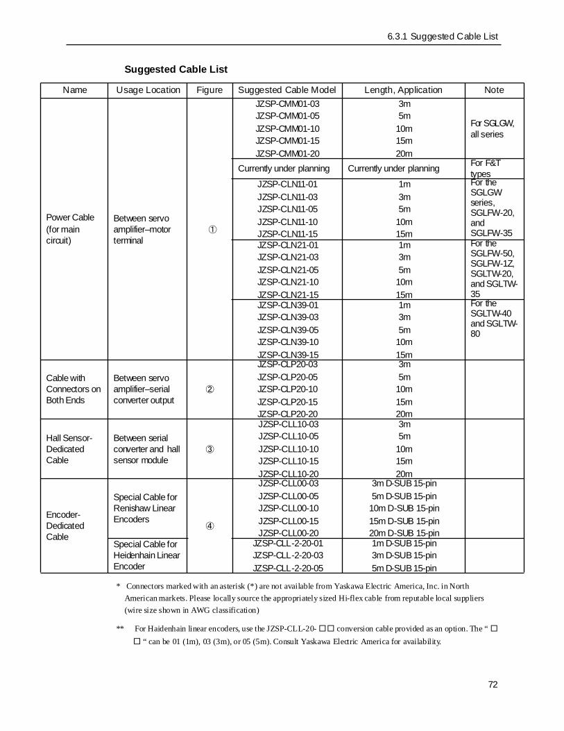
6.3.1 Suggested Cable List
72
Suggested Cable List
* Connectors marked with an asterisk (*) are not available from Yaskawa Electric America, Inc. in North American markets. Please locally source the appropriately sized Hi-flex cable from reputable local suppliers (wire size shown in AWG classification)
** For Haidenhain linear encoders, use the JZSP-CLL-20- conversion cable provided as an option. The “ “ can be 01 (1m), 03 (3m), or 05 (5m). Consult Yaskawa Electric America for availability.
Name Usage Location Figure Suggested Cable Model Length, Application Note
Power Cable(for main circuit)
Between servo amplifier–motor terminal
①
JZSP-CMM01-03JZSP-CMM01-05JZSP-CMM01-10JZSP-CMM01-15JZSP-CMM01-20
3m5m
10m15m20m
For SGLGW, all series
Currently under planning Currently under planning For F&T types
JZSP-CLN11-01JZSP-CLN11-03JZSP-CLN11-05JZSP-CLN11-10JZSP-CLN11-15
1m3m5m
10m15m
For the SGLGW series, SGLFW-20, and SGLFW-35
JZSP-CLN21-01JZSP-CLN21-03JZSP-CLN21-05JZSP-CLN21-10JZSP-CLN21-15
1m3m5m
10m15m
For the SGLFW-50, SGLFW-1Z, SGLTW-20, and SGLTW-35
JZSP-CLN39-01JZSP-CLN39-03JZSP-CLN39-05JZSP-CLN39-10JZSP-CLN39-15
1m3m5m
10m15m
For the SGLTW-40 and SGLTW-80
Cable with Connectors on Both Ends
Between servo amplifier–serial converter output
②
JZSP-CLP20-03JZSP-CLP20-05JZSP-CLP20-10JZSP-CLP20-15JZSP-CLP20-20
3m5m
10m15m20m
Hall Sensor-Dedicated Cable
Between serial converter and hall sensor module
③
JZSP-CLL10-03JZSP-CLL10-05JZSP-CLL10-10JZSP-CLL10-15JZSP-CLL10-20
3m5m
10m15m20m
Encoder-Dedicated Cable
Special Cable for Renishaw Linear Encoders
④
JZSP-CLL00-03JZSP-CLL00-05JZSP-CLL00-10JZSP-CLL00-15JZSP-CLL00-20
3m D-SUB 15-pin5m D-SUB 15-pin
10m D-SUB 15-pin15m D-SUB 15-pin20m D-SUB 15-pin
Special Cable for Heidenhain Linear Encoder
JZSP-CLL-2-20-01JZSP-CLL-2-20-03JZSP-CLL-2-20-05
1m D-SUB 15-pin3m D-SUB 15-pin5m D-SUB 15-pin

6.3.2 Dimensional Drawings of Suggested Cables
73
6.3.2 Dimensional Drawings of Suggested CablesDimensional drawings cables ② ,③ , and ④ in the above table are shown below.
6. 3. 2.1 Cable with Terminal on Both Ends②②②②
6. 3. 2.2 Hall Sensor-Dedicated Cable③③③③
6. 3. 2.3 Encoder-Dedicated Cable④④④④
<Serial Converter Unit Side><Servo Side>
L
6.8
Plug C onnect or: 55100-0600(Mol ex J apan)
17 Series Connec torConnec tor : 17JE-23090-02 (9-pi n)Dai -Ic hi D enko
<Pol e Sensor>L
< C o nv er te r U nit S id e>
17 Se ries Co nnect orConn ector : 17 JE- 230 90-0 2 (9 -pin)Dai-Ich i Denko
17 Se ries Co nnec torCon necto r: 17 JE- 230 90-0 2 (9 -pin)Dai- Ic hi Denko
< Co n ve rt er U n it Sid e>
L
17 Serie s Conn ectorCo nnec tor: 1 7JE-13 150- 02 ( 15-p in )Da i-Ichi De nko
< S ca le He a d Sid e >
17 Se ries Con necto rConn ector :17JE-1 3150 -02 (15- pin)Dai-Ich i Denko

6.3.2 Dimensional Drawings of Suggested Cables
74

Yaskawa Electric America, Inc., July 2001 Printed In U.S.A .YEA-SIA-S800-39.11
YASKAWA ELECTRIC AMERICA, INC.Chicago-Corporate Headquarters 2121 Norman Drive South, Waukegan, IL 60085, U.S.A.Phone: (847) 887-7000 Fax: (847) 887-7310 Internet: http://www.yaskawa.comMOTOMAN INC.805 Liberty Lane, West Carrollton, OH 45449, U.S.A.Phone: (937) 847-6200 Fax: (937) 847-6277 Internet: http://www.motoman.comYASKAWA ELECTRIC CORPORATIONNew Pier Takeshiba South Tower, 1-16-1, Kaigan, Minatoku, Tokyo, 105-0022, JapanPhone: 81-3-5402-4511 Fax: 81-3-5402-4580 Internet: http://www.yaskawa.co.jpYASKAWA ELETRICO DO BRASIL COMERCIO LTDA.Avenida Fagundes Filho, 620 Bairro Saude Sao Paolo-SP, Brasil CEP: 04304-000Phone: 55-11-5071-2552 Fax: 55-11-5581-8795 Internet: http://www.yaskawa.com.brYASKAWA ELECTRIC EUROPE GmbHAm Kronberger Hang 2, 65824 Schwalbach, GermanyPhone: 49-6196-569-300 Fax: 49-6196-888-301 Internet: http://www.yaskawa.deMOTOMAN ROBOTICS ABBox 504 S38525, Torsas, SwedenPhone: 46-486-48800 Fax: 46-486-41410 Internet: http://www.motoman.seMOTOMAN ROBOTEC GmbHKammerfeldstraβe 1, 85391 Allershausen, GermanyPhone: 49-8166-900 Fax: 49-8166-9039 Internet: http://www.motoman.deYASKAWA ELECTRIC UK LTD.1 Hunt Hill Orchardton Woods Cumbernauld, G68 9LF, Scotland, United KingdomPhone: 44-12-3673-5000 Fax: 44-12-3645-8182 Internet: http://www.yaskawa.co.ukYASKAWA ELECTRIC KOREA CORPORATIONPaik Nam Bldg. 901 188-3, 1-Ga Euljiro, Joong-Gu, Seoul, KoreaPhone: 82-2-776-7844 Fax: 82-2-753-2639YASKAWA ELECTRIC (SINGAPORE) PTE. LTD.Head Office: 151 Lorong Chuan, #04-01, New Tech Park Singapore 556741, SINGAPOREPhone: 65-282-3003 Fax: 65-289-3003TAIPEI OFFICE (AND YATEC ENGINEERING CORPORATION)10F 146 Sung Chiang Road, Taipei, TaiwanPhone: 886-2-2563-0010 Fax: 886-2-2567-4677YASKAWA JASON (HK) COMPANY LIMITEDRm. 2909-10, Hong Kong Plaza, 186-191 Connaught Road West, Hong KongPhone: 852-2803-2385 Fax: 852-2547-5773BEIJING OFFICE Room No. 301 Office Building of Beijing International Club,21 Jianguomanwai Avenue, Beijing 100020, ChinaPhone: 86-10-6532-1850 Fax: 86-10-6532-1851SHANGHAI OFFICE 27 Hui He Road Shanghai 200437 ChinaPhone: 86-21-6553-6600 Fax: 86-21-6531-4242SHANGHAI YASKAWA-TONJI M & E CO., LTD.27 Hui He Road Shanghai 200437 ChinaPhone: 86-21-6533-2828 Fax: 86-21-6553-6677 Internet: http://www.yaskawa-tongji.comBEIJING YASKAWA BEIKE AUTOMATION ENGINEERING CO., LTD.30 Xue Yuan Road, Haidian, Beijing 100083 China Phone: 86-10-6232-9943 Fax: 86-10-6234-5002SHOUGANG MOTOMAN ROBOT CO., LTD.7, Yongchang-North Street, Beijing Economic & Technological Development Area,Beijing 100076 ChinaPhone: 86-10-6788-0551 Fax: 86-10-6788-2878YEA, TAICHUNG OFFICE IN TAIWAINB1, 6F, No.51, Section 2, Kung-Yi Road, Taichung City, Taiwan, R.O.C.Phone: 886-4-2320-2227 Fax:886-4-2320-2239