ibml · ibml sg24-5652-00. take note! before using this information and the product it supports, be...
TRANSCRIPT

IBML
ABCs of OS/390 System ProgrammingVolume 2
P. Rogers, G. Capobianco, D. Carey, N. Davies, L. Fadel, K. Hewitt,J. Oliveira, F. Pita, A. Salla, V. Sokal, Y. F. Tay, H. Timm
International Technical Support Organization
www.redbooks.ibm.com
SG24-5652-00


International Technical Support Organization
ABCs of OS/390 System ProgrammingVolume 2
April 2000
SG24-5652-00
IBML

Take Note!
Before using this information and the product it supports, be sure to read the general information inAppendix C, “Special Notices” on page 299.
First Edition (April 2000)
This edition applies to OS/390 Version 2 Release 8, Program Number 5647-A01, and to all subsequent releasesand modifications.
Comments may be addressed to:IBM Corporation, International Technical Support OrganizationDept. HYJ Mail Station P0992455 South RoadPoughkeepsie, New York 12601-5400
When you send information to IBM, you grant IBM a non-exclusive right to use or distribute the information in anyway it believes appropriate without incurring any obligation to you.
Copyright International Business Machines Corporation 2000. All rights reserved.Note to U.S. Government Users — Documentation related to restricted rights — Use, duplication or disclosure issubject to restrictions set forth in GSA ADP Schedule Contract with IBM Corp.

Contents
Figures . . . . . . . . . . . . . . . . . . . . . . . . . . . . . . . . . . . . . . . . . . . ix
Tables . . . . . . . . . . . . . . . . . . . . . . . . . . . . . . . . . . . . . . . . . . xii i
Preface . . . . . . . . . . . . . . . . . . . . . . . . . . . . . . . . . . . . . . . . . . xvThe team that wrote this redbook . . . . . . . . . . . . . . . . . . . . . . . . . . . xvComments welcome . . . . . . . . . . . . . . . . . . . . . . . . . . . . . . . . . . xvi
Chapter 1. OS/390 implementation and daily maintenance . . . . . . . . . . . 11.1 IPL of OS/390 . . . . . . . . . . . . . . . . . . . . . . . . . . . . . . . . . . . . 2
1.1.1 Types of IPL . . . . . . . . . . . . . . . . . . . . . . . . . . . . . . . . . . 31.1.2 The IPL process . . . . . . . . . . . . . . . . . . . . . . . . . . . . . . . . 5
1.2 Basic aspects of OS/390 implementation . . . . . . . . . . . . . . . . . . . . 81.3 Overview of parmlib members . . . . . . . . . . . . . . . . . . . . . . . . . . 9
1.3.1 Syntax rules for parmlib members . . . . . . . . . . . . . . . . . . . . . 111.3.2 Types of system symbols . . . . . . . . . . . . . . . . . . . . . . . . . . 121.3.3 Static system symbols . . . . . . . . . . . . . . . . . . . . . . . . . . . . 141.3.4 Using parmlib concatenation . . . . . . . . . . . . . . . . . . . . . . . . 161.3.5 Description and use of the parmlib concatenation . . . . . . . . . . . 171.3.6 Using system symbols in parmlib . . . . . . . . . . . . . . . . . . . . . 191.3.7 Using system symbols in parmlib . . . . . . . . . . . . . . . . . . . . . 211.3.8 IEASYSxx (system parameter list) . . . . . . . . . . . . . . . . . . . . . 231.3.9 IEASYSxx and system symbols . . . . . . . . . . . . . . . . . . . . . . . 251.3.10 Create an IEASYMxx parmlib member . . . . . . . . . . . . . . . . . . 271.3.11 LOADxx (system configuration data sets) . . . . . . . . . . . . . . . . 281.3.12 Placement of LOADxx . . . . . . . . . . . . . . . . . . . . . . . . . . . . 301.3.13 How to control parmlib . . . . . . . . . . . . . . . . . . . . . . . . . . . 321.3.14 PARMLIB commands . . . . . . . . . . . . . . . . . . . . . . . . . . . . 351.3.15 Parmlib commands . . . . . . . . . . . . . . . . . . . . . . . . . . . . . 361.3.16 Use of SETLOAD command . . . . . . . . . . . . . . . . . . . . . . . . 37
1.4 Catalogs . . . . . . . . . . . . . . . . . . . . . . . . . . . . . . . . . . . . . . . 381.4.1 Using indirect catalog entries . . . . . . . . . . . . . . . . . . . . . . . . 381.4.2 Catalog management . . . . . . . . . . . . . . . . . . . . . . . . . . . . . 39
1.5 Separating data from software . . . . . . . . . . . . . . . . . . . . . . . . . . 401.6 Placing data sets on specific volumes . . . . . . . . . . . . . . . . . . . . . 41
1.6.1 SMP/E global-shared data sets . . . . . . . . . . . . . . . . . . . . . . . 421.6.2 Target libraries (TLIBs) for product sets . . . . . . . . . . . . . . . . . 431.6.3 Distribution libraries (DLIBs) for product sets . . . . . . . . . . . . . . 461.6.4 Image-related data sets . . . . . . . . . . . . . . . . . . . . . . . . . . . 471.6.5 Cluster-related data sets . . . . . . . . . . . . . . . . . . . . . . . . . . . 49
1.7 Choosing a naming convention for data sets . . . . . . . . . . . . . . . . . 511.8 DASD space utilization and performance . . . . . . . . . . . . . . . . . . . 521.9 System data sets . . . . . . . . . . . . . . . . . . . . . . . . . . . . . . . . . . 541.10 System administration tasks . . . . . . . . . . . . . . . . . . . . . . . . . . 551.11 User administration . . . . . . . . . . . . . . . . . . . . . . . . . . . . . . . . 561.12 DASD administration . . . . . . . . . . . . . . . . . . . . . . . . . . . . . . . 57
1.12.1 DASD management . . . . . . . . . . . . . . . . . . . . . . . . . . . . . 571.12.2 How to add additional DASD volumes . . . . . . . . . . . . . . . . . . 581.12.3 Implementing System Managed Storage (SMS) . . . . . . . . . . . . 601.12.4 How to deal with DASD problems . . . . . . . . . . . . . . . . . . . . . 62
1.13 System data housekeeping . . . . . . . . . . . . . . . . . . . . . . . . . . . 65
Copyright IBM Corp. 2000 iii

1.14 How to collect SMF data . . . . . . . . . . . . . . . . . . . . . . . . . . . . . 671.14.1 SMFPRMxx parmlib member . . . . . . . . . . . . . . . . . . . . . . . 691.14.2 Dumping SMF data . . . . . . . . . . . . . . . . . . . . . . . . . . . . . 71
1.15 How to create SYS1.LOGREC . . . . . . . . . . . . . . . . . . . . . . . . . . 721.15.1 How to clear SYS1.LOGREC . . . . . . . . . . . . . . . . . . . . . . . . 73
1.16 The SYSLOG . . . . . . . . . . . . . . . . . . . . . . . . . . . . . . . . . . . . 751.17 Other administration tasks . . . . . . . . . . . . . . . . . . . . . . . . . . . 77
1.17.1 How to work with Missing Interrupt Handler (MIH) . . . . . . . . . . . 781.17.2 How to add additional page data sets . . . . . . . . . . . . . . . . . . 801.17.3 How to change the TSO timeout value . . . . . . . . . . . . . . . . . . 831.17.4 How to add spool volumes . . . . . . . . . . . . . . . . . . . . . . . . . 851.17.5 How to delete spool volumes . . . . . . . . . . . . . . . . . . . . . . . 871.17.6 How to verify the system configuration . . . . . . . . . . . . . . . . . 901.17.7 How to view SYSOUT using ISPF . . . . . . . . . . . . . . . . . . . . . 951.17.8 How to change your TSO user profile . . . . . . . . . . . . . . . . . . 971.17.9 How to back up and restore OS/390 . . . . . . . . . . . . . . . . . . . 99
Chapter 2. Defining subsystems . . . . . . . . . . . . . . . . . . . . . . . . . . 1032.1 IEFSSNxx (subsystem definitions) - keyword parameter form . . . . . . 104
2.1.2 Statements and parameters for IEFSSNxx . . . . . . . . . . . . . . . 1062.2 Subsystem interface - SSI . . . . . . . . . . . . . . . . . . . . . . . . . . . . 109
2.2.1 SSI control blocks and routines . . . . . . . . . . . . . . . . . . . . . . 1102.2.2 SSI request to master subsystem . . . . . . . . . . . . . . . . . . . . 1122.2.3 JES2 supported SSI functions . . . . . . . . . . . . . . . . . . . . . . . 1132.2.4 JES3 supported SSI functions . . . . . . . . . . . . . . . . . . . . . . . 114
Chapter 3. Job Management . . . . . . . . . . . . . . . . . . . . . . . . . . . . 1153.1 OS/390 and job management . . . . . . . . . . . . . . . . . . . . . . . . . . 116
3.1.1 Understanding JCL . . . . . . . . . . . . . . . . . . . . . . . . . . . . . 1173.1.2 Job control statements . . . . . . . . . . . . . . . . . . . . . . . . . . . 119
3.2 JES2 and JES3 main differences . . . . . . . . . . . . . . . . . . . . . . . . 1213.3 JES2 . . . . . . . . . . . . . . . . . . . . . . . . . . . . . . . . . . . . . . . . . 122
3.3.1 JES2 functions . . . . . . . . . . . . . . . . . . . . . . . . . . . . . . . . 1233.3.2 JES2 - Phases of job processing . . . . . . . . . . . . . . . . . . . . . 1253.3.3 JES2 spool . . . . . . . . . . . . . . . . . . . . . . . . . . . . . . . . . . 1283.3.4 JES2 checkpointing . . . . . . . . . . . . . . . . . . . . . . . . . . . . . 1293.3.5 JES2 configurations . . . . . . . . . . . . . . . . . . . . . . . . . . . . . 1313.3.6 JES2 customization . . . . . . . . . . . . . . . . . . . . . . . . . . . . . 133
3.4 JES2 exits . . . . . . . . . . . . . . . . . . . . . . . . . . . . . . . . . . . . . 1363.4.1 JES2 job-related exits . . . . . . . . . . . . . . . . . . . . . . . . . . . 1383.4.2 JES2 - Exits in conversion phase . . . . . . . . . . . . . . . . . . . . . 1423.4.3 JES2 - Exits on execution Phase . . . . . . . . . . . . . . . . . . . . . 143
3.5 How to start JES2 . . . . . . . . . . . . . . . . . . . . . . . . . . . . . . . . . 1443.5.2 JES2 start options . . . . . . . . . . . . . . . . . . . . . . . . . . . . . . 1463.5.3 Restarting JES2 with cold start option . . . . . . . . . . . . . . . . . . 149
3.6 Stopping JES2 . . . . . . . . . . . . . . . . . . . . . . . . . . . . . . . . . . . 1513.7 JES2 operations . . . . . . . . . . . . . . . . . . . . . . . . . . . . . . . . . . 153
3.7.1 Controlling the JES2 environment . . . . . . . . . . . . . . . . . . . . 1553.7.2 Controlling a JES2 MAS environment . . . . . . . . . . . . . . . . . . 1563.7.3 Controlling JES2 spooling . . . . . . . . . . . . . . . . . . . . . . . . . 1573.7.4 Controlling JES2 jobs . . . . . . . . . . . . . . . . . . . . . . . . . . . . 1583.7.5 Controlling JES2 printers . . . . . . . . . . . . . . . . . . . . . . . . . . 159
3.8 JES3 . . . . . . . . . . . . . . . . . . . . . . . . . . . . . . . . . . . . . . . . . 1613.8.1 JES3 configuration . . . . . . . . . . . . . . . . . . . . . . . . . . . . . 1623.8.2 JES3 complex . . . . . . . . . . . . . . . . . . . . . . . . . . . . . . . . 164
iv ABCs of OS/390 System Programming

3.8.3 JES3 single processor . . . . . . . . . . . . . . . . . . . . . . . . . . . 1653.8.4 Multi-system image . . . . . . . . . . . . . . . . . . . . . . . . . . . . . 1663.8.5 Availability . . . . . . . . . . . . . . . . . . . . . . . . . . . . . . . . . . 1673.8.6 Workload balancing . . . . . . . . . . . . . . . . . . . . . . . . . . . . . 1673.8.7 Spool devices . . . . . . . . . . . . . . . . . . . . . . . . . . . . . . . . 1683.8.8 Control flexibility . . . . . . . . . . . . . . . . . . . . . . . . . . . . . . 1683.8.9 JES3 phases of job processing . . . . . . . . . . . . . . . . . . . . . . 1703.8.10 JES3 phases of job processing . . . . . . . . . . . . . . . . . . . . . 1713.8.11 JES3 operator control . . . . . . . . . . . . . . . . . . . . . . . . . . . 1733.8.12 Controlling JES3 jobs . . . . . . . . . . . . . . . . . . . . . . . . . . . 1743.8.13 Managing output service jobs . . . . . . . . . . . . . . . . . . . . . . 1753.8.14 How to start JES3 . . . . . . . . . . . . . . . . . . . . . . . . . . . . . 1763.8.15 JES3 initialization deck . . . . . . . . . . . . . . . . . . . . . . . . . . 1783.8.16 JES3 start parameter . . . . . . . . . . . . . . . . . . . . . . . . . . . 1803.8.17 How to stop JES3 . . . . . . . . . . . . . . . . . . . . . . . . . . . . . 182
3.9 Operations planning and control (OPC) . . . . . . . . . . . . . . . . . . . . 1843.9.1 Who uses TME 10 OPC . . . . . . . . . . . . . . . . . . . . . . . . . . . 1853.9.2 TME 10 OPC platforms . . . . . . . . . . . . . . . . . . . . . . . . . . . 1873.9.3 What is a TME 10 OPC Tracker . . . . . . . . . . . . . . . . . . . . . . 1893.9.4 What is a TME 10 OPC controller . . . . . . . . . . . . . . . . . . . . . 1903.9.5 TME 10 OPC as a workload management tool . . . . . . . . . . . . . 191
Chapter 4. LPA, LNKLST, and authorized libraries . . . . . . . . . . . . . . . 1934.1 Link pack area (LPA) . . . . . . . . . . . . . . . . . . . . . . . . . . . . . . . 194
4.1.1 The LPA subareas . . . . . . . . . . . . . . . . . . . . . . . . . . . . . 1954.1.2 Pageable link pack area (PLPA/extended PLPA) . . . . . . . . . . . 1974.1.3 Specifying LPA parameters in parmlib . . . . . . . . . . . . . . . . . 1984.1.4 Coding a LPALSTxx member . . . . . . . . . . . . . . . . . . . . . . . 2004.1.5 Fixed link pack area (FLPA or extended FLPA) . . . . . . . . . . . . 2014.1.6 Modified link pack area (MLPA/extended MLPA) . . . . . . . . . . . 2064.1.7 Managing dynamic LPA content . . . . . . . . . . . . . . . . . . . . . 210
4.2 The linkList (LNKLST) . . . . . . . . . . . . . . . . . . . . . . . . . . . . . . 2114.2.1 An overview of linkList (LNKLST) . . . . . . . . . . . . . . . . . . . . . 2124.2.2 Managing dynamic LNKLST content . . . . . . . . . . . . . . . . . . . 2144.2.3 The library lookaside (LLA) overview . . . . . . . . . . . . . . . . . . 2154.2.4 Virtual lookaside facility (VLF) overview . . . . . . . . . . . . . . . . . 2224.2.5 COFVLFxx parmlib member . . . . . . . . . . . . . . . . . . . . . . . . 224
4.3 The authorized libraries . . . . . . . . . . . . . . . . . . . . . . . . . . . . . 2274.3.1 Authorized libraries overview . . . . . . . . . . . . . . . . . . . . . . . 2284.3.2 Managing dynamic APF . . . . . . . . . . . . . . . . . . . . . . . . . . 234
Chapter 5. Catalogs . . . . . . . . . . . . . . . . . . . . . . . . . . . . . . . . . . 2395.1 Catalogs . . . . . . . . . . . . . . . . . . . . . . . . . . . . . . . . . . . . . . 2405.2 Introduction to ICF . . . . . . . . . . . . . . . . . . . . . . . . . . . . . . . . 241
5.2.1 Basic catalog structure (BCS) . . . . . . . . . . . . . . . . . . . . . . . 2415.2.2 VSAM volume data set (VVDS) . . . . . . . . . . . . . . . . . . . . . . 2425.2.3 VSAM volume records (VVR) . . . . . . . . . . . . . . . . . . . . . . . 2425.2.4 Non-VSAM volume record (NVR) . . . . . . . . . . . . . . . . . . . . . 242
5.3 Catalogs by function . . . . . . . . . . . . . . . . . . . . . . . . . . . . . . . 2435.3.1 Master catalog . . . . . . . . . . . . . . . . . . . . . . . . . . . . . . . . 2435.3.2 The Mastercat at system initialization . . . . . . . . . . . . . . . . . . 2445.3.3 Identifying the Mastercat . . . . . . . . . . . . . . . . . . . . . . . . . . 2455.3.4 Usercats . . . . . . . . . . . . . . . . . . . . . . . . . . . . . . . . . . . 2465.3.5 Catalog search order . . . . . . . . . . . . . . . . . . . . . . . . . . . . 247
5.4 Access method service (AMS) . . . . . . . . . . . . . . . . . . . . . . . . . 249
Contents v

5.5 Creating a basic catalog structure (BCS) . . . . . . . . . . . . . . . . . . . 2515.5.1 Defining a BCS with model . . . . . . . . . . . . . . . . . . . . . . . . 2525.5.2 Defining aliases . . . . . . . . . . . . . . . . . . . . . . . . . . . . . . . 254
5.6 Deleting data entities . . . . . . . . . . . . . . . . . . . . . . . . . . . . . . 2555.6.1 Alias . . . . . . . . . . . . . . . . . . . . . . . . . . . . . . . . . . . . . . 2555.6.2 Deleting the catalog entry . . . . . . . . . . . . . . . . . . . . . . . . . 2555.6.3 VVR and NVR records . . . . . . . . . . . . . . . . . . . . . . . . . . . 2565.6.4 Generation data group (GDG) . . . . . . . . . . . . . . . . . . . . . . 2565.6.5 Delete an ICF . . . . . . . . . . . . . . . . . . . . . . . . . . . . . . . . 2575.6.6 Delete a migrated data set . . . . . . . . . . . . . . . . . . . . . . . . 258
5.7 Requesting information from a catalog . . . . . . . . . . . . . . . . . . . . 2595.7.1 LISTCAT examples . . . . . . . . . . . . . . . . . . . . . . . . . . . . . 2595.7.2 Printing contents of a CATALOG and VVDS . . . . . . . . . . . . . . 260
5.8 The catalog address space . . . . . . . . . . . . . . . . . . . . . . . . . . . 2615.8.1 Restarting the catalog address space . . . . . . . . . . . . . . . . . . 262
5.9 Backup procedures . . . . . . . . . . . . . . . . . . . . . . . . . . . . . . . . 2635.9.1 Backing up a BCS (Mastercat or Usercat) . . . . . . . . . . . . . . . 2635.9.2 Backing up a VVDS . . . . . . . . . . . . . . . . . . . . . . . . . . . . . 2645.9.3 Backing up a Mastercat . . . . . . . . . . . . . . . . . . . . . . . . . . 264
5.10 Recovery procedures . . . . . . . . . . . . . . . . . . . . . . . . . . . . . 2655.11 Protecting catalogs . . . . . . . . . . . . . . . . . . . . . . . . . . . . . . . 267
5.11.1 RACF authorization checking . . . . . . . . . . . . . . . . . . . . . . 2675.11.2 Profiles . . . . . . . . . . . . . . . . . . . . . . . . . . . . . . . . . . . . 268
5.12 Merging catalogs . . . . . . . . . . . . . . . . . . . . . . . . . . . . . . . . 2695.13 Splitting a catalog . . . . . . . . . . . . . . . . . . . . . . . . . . . . . . . . 2715.14 Catalog performance . . . . . . . . . . . . . . . . . . . . . . . . . . . . . . 273
5.14.1 Factors affecting catalog performance . . . . . . . . . . . . . . . . . 2735.14.2 Eliminating JOBCAT and STEPCAT DD . . . . . . . . . . . . . . . . 2735.14.3 Caching catalogs . . . . . . . . . . . . . . . . . . . . . . . . . . . . . . 2745.14.4 Monitoring the CAS . . . . . . . . . . . . . . . . . . . . . . . . . . . . 2765.14.5 Monitoring the CAS performance . . . . . . . . . . . . . . . . . . . . 2785.14.6 Monitoring the CDSC performance . . . . . . . . . . . . . . . . . . . 279
5.15 Using multiple catalogs . . . . . . . . . . . . . . . . . . . . . . . . . . . . 2805.15.1 Sharing catalogs . . . . . . . . . . . . . . . . . . . . . . . . . . . . . . 2815.15.2 DFSMS enhanced catalog sharing . . . . . . . . . . . . . . . . . . . 283
Appendix A. OS/390 installation and customization . . . . . . . . . . . . . . . 285A.1 SYS1.PARMLIB members . . . . . . . . . . . . . . . . . . . . . . . . . . . . 285A.2 IEASYSxx SYS1.PARMLIB parameters . . . . . . . . . . . . . . . . . . . . 287A.3 System data sets . . . . . . . . . . . . . . . . . . . . . . . . . . . . . . . . . 291
Appendix B. Job Management . . . . . . . . . . . . . . . . . . . . . . . . . . . 295B.1 Example of a JES2 Initialization Data Set . . . . . . . . . . . . . . . . . . 295
Appendix C. Special Notices . . . . . . . . . . . . . . . . . . . . . . . . . . . . 299
Appendix D. Related Publications . . . . . . . . . . . . . . . . . . . . . . . . . 301D.1 IBM Redbooks . . . . . . . . . . . . . . . . . . . . . . . . . . . . . . . . . . 301D.2 IBM Redbooks collections . . . . . . . . . . . . . . . . . . . . . . . . . . . 302D.3 Other resources . . . . . . . . . . . . . . . . . . . . . . . . . . . . . . . . . 302
How to get IBM Redbooks . . . . . . . . . . . . . . . . . . . . . . . . . . . . . . 305IBM Redbooks fax order form . . . . . . . . . . . . . . . . . . . . . . . . . . . . 306
Glossary . . . . . . . . . . . . . . . . . . . . . . . . . . . . . . . . . . . . . . . . . 307
vi ABCs of OS/390 System Programming

IBM Redbooks evaluation . . . . . . . . . . . . . . . . . . . . . . . . . . . . . . 321
Contents vii

viii ABCs of OS/390 System Programming

Figures
1. Initialization of OS/390 . . . . . . . . . . . . . . . . . . . . . . . . . . . . . . 2 2. Types of IPLs . . . . . . . . . . . . . . . . . . . . . . . . . . . . . . . . . . . 3 3. Initial program load . . . . . . . . . . . . . . . . . . . . . . . . . . . . . . . . 5 4. System planning . . . . . . . . . . . . . . . . . . . . . . . . . . . . . . . . . 8 5. Overview of parmlib members . . . . . . . . . . . . . . . . . . . . . . . . . 9 6. Syntax rules for parmlib members . . . . . . . . . . . . . . . . . . . . . . . 11 7. System symbols . . . . . . . . . . . . . . . . . . . . . . . . . . . . . . . . . . 12 8. System symbols . . . . . . . . . . . . . . . . . . . . . . . . . . . . . . . . . . 14 9. Logical parmlib . . . . . . . . . . . . . . . . . . . . . . . . . . . . . . . . . . 1610. Parmlib concatenation . . . . . . . . . . . . . . . . . . . . . . . . . . . . . . 1711. Using system symbols in parmlib . . . . . . . . . . . . . . . . . . . . . . . 1912. Using system symbols in parmlib . . . . . . . . . . . . . . . . . . . . . . . 2113. IEASYSxx member . . . . . . . . . . . . . . . . . . . . . . . . . . . . . . . . 2314. IEASYSxx and system symbols . . . . . . . . . . . . . . . . . . . . . . . . . 2515. IEASYMxx parmlib member . . . . . . . . . . . . . . . . . . . . . . . . . . . 2716. LOADxx parmlib member . . . . . . . . . . . . . . . . . . . . . . . . . . . . 2817. Placement of LOADxx . . . . . . . . . . . . . . . . . . . . . . . . . . . . . . 3018. Controlling parmlib . . . . . . . . . . . . . . . . . . . . . . . . . . . . . . . . 3219. Parmlib commands . . . . . . . . . . . . . . . . . . . . . . . . . . . . . . . . 3520. Parmlib commands . . . . . . . . . . . . . . . . . . . . . . . . . . . . . . . . 3621. Parmlib commands output . . . . . . . . . . . . . . . . . . . . . . . . . . . 3722. Catalogs . . . . . . . . . . . . . . . . . . . . . . . . . . . . . . . . . . . . . . 3823. Separating data from software . . . . . . . . . . . . . . . . . . . . . . . . . 4024. Data set placement . . . . . . . . . . . . . . . . . . . . . . . . . . . . . . . . 4125. The TLIBs volumes . . . . . . . . . . . . . . . . . . . . . . . . . . . . . . . . 4326. The DLIBs volumes . . . . . . . . . . . . . . . . . . . . . . . . . . . . . . . . 4627. The image-related volumes . . . . . . . . . . . . . . . . . . . . . . . . . . . 4728. The cluster-related volumes . . . . . . . . . . . . . . . . . . . . . . . . . . 4929. Naming conventions for data sets . . . . . . . . . . . . . . . . . . . . . . . 5130. DASD space utilization and performance . . . . . . . . . . . . . . . . . . . 5231. System data sets . . . . . . . . . . . . . . . . . . . . . . . . . . . . . . . . . 5432. System administration . . . . . . . . . . . . . . . . . . . . . . . . . . . . . . 5533. User administration . . . . . . . . . . . . . . . . . . . . . . . . . . . . . . . . 5634. DASD administration . . . . . . . . . . . . . . . . . . . . . . . . . . . . . . . 5735. Adding a new DASD volume . . . . . . . . . . . . . . . . . . . . . . . . . . 5836. Implementing SMS . . . . . . . . . . . . . . . . . . . . . . . . . . . . . . . . 6037. Handling DASD problems . . . . . . . . . . . . . . . . . . . . . . . . . . . . 6238. Sample JCL for the ANALYZE command . . . . . . . . . . . . . . . . . . . 6339. Sample JCL for the INSPECT command . . . . . . . . . . . . . . . . . . . 6440. System data housekeeping . . . . . . . . . . . . . . . . . . . . . . . . . . . 6541. SMF data . . . . . . . . . . . . . . . . . . . . . . . . . . . . . . . . . . . . . . 6742. Sample JCL to allocate new SMF data sets . . . . . . . . . . . . . . . . . 6843. SMFPRMxx parmlib member . . . . . . . . . . . . . . . . . . . . . . . . . . 6944. Activating the changes to the SMF parameters . . . . . . . . . . . . . . . 7045. Dumping SMF data . . . . . . . . . . . . . . . . . . . . . . . . . . . . . . . . 7146. LOGREC data . . . . . . . . . . . . . . . . . . . . . . . . . . . . . . . . . . . 7247. Sample JCL to create and initialize a new LOGREC data set . . . . . . . 7348. Sample JCL to clear the LOGREC data set . . . . . . . . . . . . . . . . . . 7349. The SYSLOG data set . . . . . . . . . . . . . . . . . . . . . . . . . . . . . . 7550. Example of HARDCOPY statement in CONSOLxx . . . . . . . . . . . . . . 7551. Other administration tasks . . . . . . . . . . . . . . . . . . . . . . . . . . . 77
Copyright IBM Corp. 2000 ix

52. Working with MIH . . . . . . . . . . . . . . . . . . . . . . . . . . . . . . . . . 7853. Example of IECIOSxx . . . . . . . . . . . . . . . . . . . . . . . . . . . . . . . 7954. Using the SET command to activate the IECIOSxx changes . . . . . . . . 7955. Adding page data sets . . . . . . . . . . . . . . . . . . . . . . . . . . . . . . 8056. Sample JCL to define a new page data set . . . . . . . . . . . . . . . . . 8157. Adding the new page data set to the system . . . . . . . . . . . . . . . . 8158. Checking the status of the auxiliary storage . . . . . . . . . . . . . . . . . 8159. Updating the PAGE parameter in IEASYSxx . . . . . . . . . . . . . . . . . 8260. Changing TSO timeout . . . . . . . . . . . . . . . . . . . . . . . . . . . . . . 8361. Example of SMFPRMxx member . . . . . . . . . . . . . . . . . . . . . . . . 8462. Adding spool volumes . . . . . . . . . . . . . . . . . . . . . . . . . . . . . . 8563. SPOOLDEF statement . . . . . . . . . . . . . . . . . . . . . . . . . . . . . . 8564. $S SPL command . . . . . . . . . . . . . . . . . . . . . . . . . . . . . . . . . 8665. $D SPL command . . . . . . . . . . . . . . . . . . . . . . . . . . . . . . . . . 8666. Deletion of spool volumes . . . . . . . . . . . . . . . . . . . . . . . . . . . . 8767. System response to the $Z command . . . . . . . . . . . . . . . . . . . . . 8868. System response to a $P SPL command when the system is running . 8869. Example of $ SPL,P,CANCEL command . . . . . . . . . . . . . . . . . . . . 8970. Verify system configuration . . . . . . . . . . . . . . . . . . . . . . . . . . . 9071. Creating CONFIGxx member in batch . . . . . . . . . . . . . . . . . . . . . 9372. View SYSOUT using ISPF . . . . . . . . . . . . . . . . . . . . . . . . . . . . 9573. Job status information display . . . . . . . . . . . . . . . . . . . . . . . . . 9674. Status display for a particular job . . . . . . . . . . . . . . . . . . . . . . . 9675. Changing your TSO profile . . . . . . . . . . . . . . . . . . . . . . . . . . . 9776. Backup and restore of OS/390 . . . . . . . . . . . . . . . . . . . . . . . . . 9977. Sample JCL for a full volume dump . . . . . . . . . . . . . . . . . . . . . 10078. Sample JCL for an incremental dump . . . . . . . . . . . . . . . . . . . . 10079. Sample JCL for backing up selective data sets . . . . . . . . . . . . . . 10180. IEFSSNxx member . . . . . . . . . . . . . . . . . . . . . . . . . . . . . . . 10481. Statements and parameters for IEFSSNxx . . . . . . . . . . . . . . . . . 10682. Subsystem interface - SSI . . . . . . . . . . . . . . . . . . . . . . . . . . 10983. SSI control blocks and routines . . . . . . . . . . . . . . . . . . . . . . . 11084. SSI request to master subsystem . . . . . . . . . . . . . . . . . . . . . . 11285. JES2 supported SSI funcitons . . . . . . . . . . . . . . . . . . . . . . . . . 11386. JES3 supported SSI functions . . . . . . . . . . . . . . . . . . . . . . . . . 11487. OS/390 and job management . . . . . . . . . . . . . . . . . . . . . . . . . 11688. Job management . . . . . . . . . . . . . . . . . . . . . . . . . . . . . . . . 11789. JCL-related actions (user and MVS) . . . . . . . . . . . . . . . . . . . . . 11990. Submit the JCL to the System as a Job . . . . . . . . . . . . . . . . . . . 12091. JES2 and JES3 main differences . . . . . . . . . . . . . . . . . . . . . . . 12192. JES2 . . . . . . . . . . . . . . . . . . . . . . . . . . . . . . . . . . . . . . . . 12293. Relationship of JES2 to BCP . . . . . . . . . . . . . . . . . . . . . . . . . 12394. JES2 job fLow . . . . . . . . . . . . . . . . . . . . . . . . . . . . . . . . . . 12595. Spool data set . . . . . . . . . . . . . . . . . . . . . . . . . . . . . . . . . . 12896. JES2 checkpoint data set . . . . . . . . . . . . . . . . . . . . . . . . . . . 12997. JES2 example of a NJE configuration . . . . . . . . . . . . . . . . . . . . 13198. JES2 customization . . . . . . . . . . . . . . . . . . . . . . . . . . . . . . . 13399. Areas of JES2 modification . . . . . . . . . . . . . . . . . . . . . . . . . . 136100. JES2 - Exits on input phase . . . . . . . . . . . . . . . . . . . . . . . . . . 138101. JES2 - Exits in conversion phase . . . . . . . . . . . . . . . . . . . . . . . 142102. JES2 - Exits on execution Phase . . . . . . . . . . . . . . . . . . . . . . . 143103. JES2 start procedure . . . . . . . . . . . . . . . . . . . . . . . . . . . . . . 144104. JES2 start options . . . . . . . . . . . . . . . . . . . . . . . . . . . . . . . . 146105. Restarting JES2 . . . . . . . . . . . . . . . . . . . . . . . . . . . . . . . . . 149106. Stopping JES2 . . . . . . . . . . . . . . . . . . . . . . . . . . . . . . . . . . 151
x ABCs of OS/390 System Programming

107. JES2 operations . . . . . . . . . . . . . . . . . . . . . . . . . . . . . . . . . 153108. Controlling the JES2 environment . . . . . . . . . . . . . . . . . . . . . . 155109. Controlling a JES2 MAS environment . . . . . . . . . . . . . . . . . . . . 156110. Controlling JES2 spooling . . . . . . . . . . . . . . . . . . . . . . . . . . . 157111. Controlling JES2 jobs . . . . . . . . . . . . . . . . . . . . . . . . . . . . . . 158112. Controlling JES2 printers . . . . . . . . . . . . . . . . . . . . . . . . . . . 159113. JES3 . . . . . . . . . . . . . . . . . . . . . . . . . . . . . . . . . . . . . . . . 161114. JES3 configuration . . . . . . . . . . . . . . . . . . . . . . . . . . . . . . . 162115. JES3 complex . . . . . . . . . . . . . . . . . . . . . . . . . . . . . . . . . . 164116. JES3 in a single-processor environment . . . . . . . . . . . . . . . . . . 165117. JES3 multiprocessing . . . . . . . . . . . . . . . . . . . . . . . . . . . . . . 166118. Spooling to collect job output . . . . . . . . . . . . . . . . . . . . . . . . . 168119. JES3 job flow . . . . . . . . . . . . . . . . . . . . . . . . . . . . . . . . . . 170120. JES3 job flow . . . . . . . . . . . . . . . . . . . . . . . . . . . . . . . . . . 171121. JES3 commands . . . . . . . . . . . . . . . . . . . . . . . . . . . . . . . . . 173122. Controlling JES3 jobs . . . . . . . . . . . . . . . . . . . . . . . . . . . . . . 174123. Managing output service jobs . . . . . . . . . . . . . . . . . . . . . . . . 175124. JES3 start procedure . . . . . . . . . . . . . . . . . . . . . . . . . . . . . . 176125. JES3 initialization deck . . . . . . . . . . . . . . . . . . . . . . . . . . . . . 178126. JES3 start parameter . . . . . . . . . . . . . . . . . . . . . . . . . . . . . . 180127. TME 10 OPC . . . . . . . . . . . . . . . . . . . . . . . . . . . . . . . . . . . 184128. TME 10 OPC platforms . . . . . . . . . . . . . . . . . . . . . . . . . . . . . 187129. OS/390 OPC Configuration . . . . . . . . . . . . . . . . . . . . . . . . . . 189130. Link pack area . . . . . . . . . . . . . . . . . . . . . . . . . . . . . . . . . . 195131. Pageable link pack area . . . . . . . . . . . . . . . . . . . . . . . . . . . . 197132. LPA parmlib definitions . . . . . . . . . . . . . . . . . . . . . . . . . . . . 198133. Example of overriding the IEASYSxx LPA parameter . . . . . . . . . . . 198134. Coding a LPALSTxx parmlib member . . . . . . . . . . . . . . . . . . . . 200135. Fixed link pack area . . . . . . . . . . . . . . . . . . . . . . . . . . . . . . 201136. Coding the IEAFIXxx member . . . . . . . . . . . . . . . . . . . . . . . . . 202137. Specifying the IEAFIXxx member . . . . . . . . . . . . . . . . . . . . . . . 204138. Example of overriding the FIX parameter value . . . . . . . . . . . . . . 205139. Modified link pack area . . . . . . . . . . . . . . . . . . . . . . . . . . . . 206140. Coding the IEALPAxx member . . . . . . . . . . . . . . . . . . . . . . . . 207141. Specifying the IEALPAxx member . . . . . . . . . . . . . . . . . . . . . . 208142. Example of overriding the MLPA parameter value . . . . . . . . . . . . 209143. Managing dynamic LPA content . . . . . . . . . . . . . . . . . . . . . . . 210144. The LNKLST . . . . . . . . . . . . . . . . . . . . . . . . . . . . . . . . . . . 212145. Example of overriding the LNK parameter value . . . . . . . . . . . . . 213146. Dynamic LNKLST functions . . . . . . . . . . . . . . . . . . . . . . . . . . 214147. Library lookaside . . . . . . . . . . . . . . . . . . . . . . . . . . . . . . . . 215148. Dynamic LNKLST functions . . . . . . . . . . . . . . . . . . . . . . . . . . 217149. Compressing LLA-managed libraries . . . . . . . . . . . . . . . . . . . . 220150. Virtual lookaside facility . . . . . . . . . . . . . . . . . . . . . . . . . . . . 222151. COFVLFxx parmlib member . . . . . . . . . . . . . . . . . . . . . . . . . . 224152. An example of COFVLFxx . . . . . . . . . . . . . . . . . . . . . . . . . . . 225153. The authorized libraries . . . . . . . . . . . . . . . . . . . . . . . . . . . . 228154. How to get APF authorization . . . . . . . . . . . . . . . . . . . . . . . . . 231155. An example of IEAAPFxx . . . . . . . . . . . . . . . . . . . . . . . . . . . 232156. Example of PROGxx . . . . . . . . . . . . . . . . . . . . . . . . . . . . . . 233157. Dynamic APF functions . . . . . . . . . . . . . . . . . . . . . . . . . . . . 234158. Example of SET PROGxx command to activate an APF list change . . 235159. Activating a change to add an APF library . . . . . . . . . . . . . . . . . 235160. Catalogs . . . . . . . . . . . . . . . . . . . . . . . . . . . . . . . . . . . . . 240161. Introduction to ICF . . . . . . . . . . . . . . . . . . . . . . . . . . . . . . . 241
Figures xi

162. Master catalog . . . . . . . . . . . . . . . . . . . . . . . . . . . . . . . . . 243163. Identifying the Mastercat . . . . . . . . . . . . . . . . . . . . . . . . . . . 245164. Using aliases . . . . . . . . . . . . . . . . . . . . . . . . . . . . . . . . . . 246165. The catalog search order . . . . . . . . . . . . . . . . . . . . . . . . . . . 247166. Access method service . . . . . . . . . . . . . . . . . . . . . . . . . . . . 249167. Creating a basic catalog structure . . . . . . . . . . . . . . . . . . . . . . 251168. Defining a BCS with model . . . . . . . . . . . . . . . . . . . . . . . . . . 252169. Defining aliases . . . . . . . . . . . . . . . . . . . . . . . . . . . . . . . . . 254170. Deleting a data set . . . . . . . . . . . . . . . . . . . . . . . . . . . . . . . 255171. Example DEFINE RECATALOG command . . . . . . . . . . . . . . . . . . 256172. Example DELETE VVR command . . . . . . . . . . . . . . . . . . . . . . . 256173. Example of deleting a GDB catalog entry . . . . . . . . . . . . . . . . . . 256174. Example of deleting and replacing a user catalog . . . . . . . . . . . . 257175. Example of deleting an empty user catalog . . . . . . . . . . . . . . . . 257176. Listing a catalog . . . . . . . . . . . . . . . . . . . . . . . . . . . . . . . . 259177. Example of using LISTCAT to list aliases for a catalog . . . . . . . . . . 259178. Example of using LISTCAT to list all user catalogs . . . . . . . . . . . . 260179. Example of listing all information from a catalog . . . . . . . . . . . . . 260180. Example of a VVDS print . . . . . . . . . . . . . . . . . . . . . . . . . . . . 260181. The catalog address space . . . . . . . . . . . . . . . . . . . . . . . . . . 261182. Backup procedures . . . . . . . . . . . . . . . . . . . . . . . . . . . . . . . 263183. Recover procedures . . . . . . . . . . . . . . . . . . . . . . . . . . . . . . 265184. RACF . . . . . . . . . . . . . . . . . . . . . . . . . . . . . . . . . . . . . . . 267185. Merging catalogs . . . . . . . . . . . . . . . . . . . . . . . . . . . . . . . . 269186. Splitting catalogs . . . . . . . . . . . . . . . . . . . . . . . . . . . . . . . . 271187. Catalog performance . . . . . . . . . . . . . . . . . . . . . . . . . . . . . . 273188. Monitoring the CAS . . . . . . . . . . . . . . . . . . . . . . . . . . . . . . . 276189. Monitoring the CAS performance . . . . . . . . . . . . . . . . . . . . . . 278190. Monitoring the CDSC performance . . . . . . . . . . . . . . . . . . . . . 279191. Use multiple catalogs . . . . . . . . . . . . . . . . . . . . . . . . . . . . . 280192. Sharing catalogs . . . . . . . . . . . . . . . . . . . . . . . . . . . . . . . . 281193. DFSMS enhanced catalog sharing . . . . . . . . . . . . . . . . . . . . . . 283
xii ABCs of OS/390 System Programming

Tables
1. JES2 job-related exits . . . . . . . . . . . . . . . . . . . . . . . . . . . . . 139 2. Some SMF job-related exits . . . . . . . . . . . . . . . . . . . . . . . . . . 141 3. JES2 Start Parameter . . . . . . . . . . . . . . . . . . . . . . . . . . . . . 147 4. Some AMS commands that can be used with catalogs . . . . . . . . . 249 5. Overview of parmlib members . . . . . . . . . . . . . . . . . . . . . . . . 285 6. Overview of IEASYSxx parameters . . . . . . . . . . . . . . . . . . . . . 287
Copyright IBM Corp. 2000 xiii

xiv ABCs of OS/390 System Programming

Preface
This redbook is Volume 2 of a five-volume set that is designed to introduce thestructure of an OS/390 and S/390 operating environment. The set will help youinstall, tailor, and configure an OS/390 operating system, and is intended forsystem programmers who are new to an OS/390 environment.
Chapter 1 provides an introduction to OS/390 implementation and dailymaintenance, and how to IPL an OS/390 system. Described are the mainparameters and system data sets necessary to IPL and run an OS/390 operatingsystem and the main daily tasks that a system programmer performs in order tomaximize the advantages that a well implemented operating system can offer toyour I/T structure.
Chapter 2 describes subsystems and how to define them.
Chapter 3 describes the two job entry subsystems, JES2 and JES3.
Chapter 4 describes what factors should be considered when placing loadmodules or load libraries into storage.
Chapter 5 describes how data sets are managed in a catalog structure and thevarious types of catalogs.
The team that wrote this redbookThis redbook was produced by a team of specialists from around the worldworking at the International Technical Support Organization PoughkeepsieCenter.
Paul Rogers is an OS/390 specialist at the International Technical SupportOrganization, Poughkeepsie Center. He writes extensively and teaches IBMclasses worldwide on various aspects of OS/390. Before joining the ITSO 11years ago, he worked in the IBM Installation Support Center (ISC) in Greenford,England as OS/390 and JES support for IBM EMEA.
Guillermo Capobianco is an IT Specialist in IBM Global Services PSS Argentina.He has five years of experience working with customers on MVS, MVS-relatedprogram products, and OS/390. He is currently leading a technical groupproviding on-site customer support for the OS/390 platform.
David Carey is a Senior IT Availability Specialist with the IBM Support Center inSydney, Australia, where he provides defect and nondefect support for CICS,CICSPlex/SM, MQSeries, and OS/390. David has 19 years of experience withinthe information technology industry, and was an MVS systems programmer for12 years prior to joining IBM.
T. Nigel Davies is a Systems Specialist in IBM Global Services Product SupportServices (PSS) in the United Kingdom. He has 10 years of IT experience invarious roles, ranging from operations to PC and LAN support to mainframesystems programming. He joined IBM in 1997 with eight years of experience asa VM/VSE systems programmer, and since joining IBM has cross-trained inOS/390 systems skills. His areas of expertise include VM and VSE systems
Copyright IBM Corp. 2000 xv

programming, installation, and technical support, and more recently, OS/390installation and support.
Luiz Fadel - IBM Brazil
Ken Hewitt is an IT Specialist in IBM Australia. He has over 10 years ofexperience working with S/390 customers in a range of roles from CE to SystemEngineer. His areas of expertise include I/O and OSA configuration.
Joao Natalino Oliveira
Joao Natalino de Oliveira is a certified I/T consulting specialist working for theS/390 in Brazil providing support for Brazil and Latin America. He has 24 yearsof experience in large systems including MVS-OS/390. His areas of expertiseinclude performance and capacity planning, server consolidation and systemprogramming. He has a bachelor degree in Math and Data Processing fromFundação Santo André Brazil.
Fabio Chaves Pita - IBM Brazil
Alvaro Salla has 30 years of experience in OS operating systems (since MVT).He has written several redbooks on S/390 subjects. Retired from IBM Brasil, heis now a consultant for IBM customers.
Valeria Sokal is an MVS system programmer at Banco do Brasil. She has 11years of experience in the mainframe arena. Her areas of expertise includeMVS, TSO/ISPF, SLR, and WLM.
Yoon Foh Tay is an IT Specialist with IBM Singapore PSS (S/390). He has sixyears of experience on the S/390 platform, providing on-site support tocustomers.
Hans-Juergen Timm is an Advisory Systems Engineer in IBM Global ServicesPSS Germany. He has 20 years of experience working with customers in theareas of MVS and OS/390, software and technical support, and planning andmanagement. He also worked six years as an MVS Instructor in the IBMEducation Centers in Mainz and Essen, Germany. His areas of expertise includeimplementation support for OS/390, Parallel Sysplex, UNIX System Services, andBatch Management.
Comments welcomeYour comments are important to us!
We want our redbooks to be as helpful as possible. Please send us yourcomments about this or other redbooks in one of the following ways:
• Fax the evaluation form found in “IBM Redbooks evaluation” on page 321 tothe fax number shown on the form.
• Use the online evaluation form found at http://www.redbooks.ibm.com/
• Send your comments in an Internet note to [email protected]
xvi ABCs of OS/390 System Programming

Chapter 1. OS/390 implementation and daily maintenance
Regardless of which method you use to install the OS/390 operating system (ServerPac, CBPDO...) it ishighly recommended that you understand the basic aspects of the OS/390 implementation, frominstallation, to preparing to do daily activities after IPL.
This chapter will give you an overview of the basics as well as the IPL process. We will describe themain parameters and system data sets necessary to IPL and run an OS/390 operating system and themain daily tasks that a system programmer performs in order to maximize the advantages that awell-implemented operating system can offer to your IT structure.
Copyright IBM Corp. 2000 1

Figure 1. Initialization of OS/390
1.1 IPL of OS/390
When the system hardware is ready, you can use the system console to load the system software.
During initialization of an OS/390 system, the operator uses the system console, which is connected tothe processor controller or support element. From the system console, the operator initializes thesystem control program during the nucleus initialization program (NIP) stage.
During the NIP stage, the system might prompt the operator to provide system parameters that controlthe operation of MVS. The system also issues informational messages that inform the operator aboutthe stages the initialization process.
The LOADxx parmlib member allows your installation to control the initialization process. Forexample, in LOADxx, you specify IEASYSxx or IEASYMxx members that the system is to use; thesystem does not prompt the operator for system parameters that are specified in those members.Instead, it uses the values in those members.
The definition of these parameters are discussed in this chapter.
2 ABCs of OS/390 System Programming
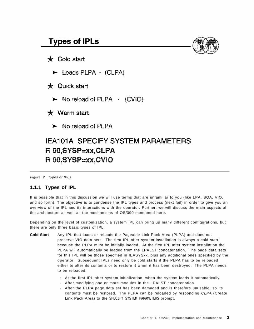
Figure 2. Types of IPLs
1.1.1 Types of IPL
It is possible that in this discussion we will use terms that are unfamiliar to you (like LPA, SQA, VIO,and so forth). The objective is to condense the IPL types and process (next foil) in order to give you anoverview of the IPL and its interactions with the operator. Further, we will discuss the main aspects ofthe architecture as well as the mechanisms of OS/390 mentioned here.
Depending on the level of customization, a system IPL can bring up many different configurations, butthere are only three basic types of IPL:
Cold Start Any IPL that loads or reloads the Pageable Link Pack Area (PLPA) and does notpreserve VIO data sets. The first IPL after system installation is always a cold startbecause the PLPA must be initially loaded. At the first IPL after system installation thePLPA will automatically be loaded from the LPALST concatenation. The page data setsfor this IPL will be those specified in IEASYSxx, plus any additional ones specified by theoperator. Subsequent IPLs need only be cold starts if the PLPA has to be reloadedeither to alter its contents or to restore it when it has been destroyed. The PLPA needsto be reloaded:
• At the first IPL after system initialization, when the system loads it automatically• After modifying one or more modules in the LPALST concatenation• After the PLPA page data set has been damaged and is therefore unusable, so its
contents must be restored. The PLPA can be reloaded by responding CLPA (CreateLink Pack Area) to the SPECIFY SYSTEM PARAMETERS prompt.
Chapter 1. OS/390 Implementation and Maintenance 3

Quick Start Any IPL that does not reload the PLPA and does not preserve VIO data sets. Thesystem will re-create page and segment tables to match the in-use PLPA. You wouldnormally perform a Quick Start IPL after a power up. The PLPA from the previoussession can be used without reloading it from the LPALST concatenation. A Quick Startcan be initiated by replying CVIO (Clear VIO) to the SPECIFY SYSTEM PARAMETERS prompt.
Warm Start Any IPL that does not reload the PLPA and preserves journaled VIO data sets. Theoperator does not enter CLPA or CVIO at the SPECIFY SYSTEM PARAMETERS prompt. Anydefinitions of existing page data sets as non-VIO local page data sets are preserved.
1.1.1.1 System Parameters promptIf the LOADPARM has been set to indicate the operator should be prompted for system parameters (A,P, S or T), NIP issues the following prompt on the NIP console:
� �IEA101A SPECIFY SYSTEM PARAMETERS� �
At this point, the operator can respond in one of a number of ways:
• Pressing Enter will cause the system to use the parameters as coded in SYS1.PARMLIB(IEASYS00).
• Entering SYSP=xx will cause the parameters in SYS1.PARMLIB(IEASYSxx) to be used.
• Entering multiple IEASYSxx members, SYSP=(xx,yy,..), for multiple concatenations to be used.
Specifying any of the individual parameters that appear in IEASYSxx will cause these parameters to beused instead of the ones coded in IEASYSxx except PAGE parameters. If multiple IEASYSxx membersare searched, the system always reads IEASYS00 first, followed by the additional ones you specify. Ifthe same parameters are found in one or more IEASYSxx members, the latest overriding parameter isused.
1.1.1.2 PAGE parameters
The PAGE parameter allows the installation to name page data sets as additions to existing page datasets. The maximum number of page data sets is 256, which includes the optional page data setspecified by the DUPLEX parameter. The system determines which page data sets to use by merginginformation from three sources: IEASYS00, IEASYSxx, and the PAGE parameter.
During system initialization, the system first uses the list of page data sets specified on the PAGEparameter of the IEASYS00 parmlib member. It then uses any other IEASYSxx parmlib member(identified via the SYSP=xx parameter). The IEASYSxx PAGE data set name list overrides the one inIEASYS00.
4 ABCs of OS/390 System Programming

Figure 3. Initial program load
1.1.2 The IPL processAn Initial Program Load (IPL) is the act of loading a copy of the operating system from disk into theCPU′s central storage and executing it. Not all disks attached to a CPU will have loadable code onthem. A disk that does is generally referred to as an IPLable disk, and more specifically as theSYSRES volume.
IPLable disks will contain a bootstrap module at cylinder 0 track 0. At IPL, this bootstrap is loaded intostorage at real address zero and control is passed to it. The bootstrap then reads the IPL controlprogram IEAIPL00 (also known as IPL text) and passes control to it. This in turn starts the morecomplex task of loading the operating system and executing it.
Attempts to IPL from a disk that does not contain IPL text results in an error condition.
IEAIPL00 prepares an environment suitable for starting the programs and modules that make up theoperating system. First, it clears central storage to zeros before defining storage areas for the masterscheduler. It then locates the SYS1.NUCLEUS data set on the SYSRES volume and loads a series ofprograms from it known as IPL Resource Initialization Modules (IRIMs). These IRIMs will then start toconstruct the normal operating system environment of control blocks and subsystems that make up anOS/390 system. Some of the more significant tasks performed by the IRIMs are to:
• Read the LOADPARM information entered on the hardware console at the time the IPL commandwas executed. LOADPARM is discussed in 1.1.2.1, “The Load Parameter (LOADPARM)” onpage 6.
Chapter 1. OS/390 Implementation and Maintenance 5

• Search the volume specified in the LOADPARM as containing the IODF data set for the LOADxxmember—the value of xx is also taken from the LOADPARM. IRIM will first attempt to locateLOADxx in SYS0.IPLPARM. If this is unsuccessful, it will look for SYS1.IPLPARM and so on up toand including SYS9.IPLPARM. If, at this point, it still has not been located, the search will continuein SYS1.PARMLIB.
When a LOADxx member has been successfully located it will be opened and information includingthe nucleus suffix (unless overridden in LOADPARM), the master catalog name, and the suffix ofthe IEASYSxx member to be used, will be read from it.
• Load the MVS nucleus.
• Initialize virtual storage in the master scheduler address space for the System Queue Area (SQA),the Extended SQA (ESQA), the Local SQA (LSQA), and the Prefixed Save Area (PSA). At the end ofthe IPL sequence, the PSA will replace IEAIPL00 at real storage location zero, where it will thenstay.
• Initialize real storage management, including the segment table for the master scheduler, segmenttable entries for common storage areas, and the page frame table.
The last of the IRIMs then loads the first part of the Nucleus Initialization Program (NIP), which theninvokes the Resource Initialization Modules (RIMs), one of the earliest of which starts upcommunications with the NIP console defined in SYS1.NUCLEUS.
1.1.2.1 The Load Parameter (LOADPARM)
The most basic level of control is through the Load Parameter (LOADPARM). This is aneight-character value made up of four fields that the operating system will refer to as it IPLs, causing itto take the specified actions. The LOADPARM is made up of the following components:
IODF ccuu The IODF device address. This is also the device on which the search for the LOADxxmember of SYSn.IPLPARM or SYS1.PARMLIB begins. The first four characters of theLOADPARM specify the hexadecimal device address for the device that contains the I/ODefinition File (IODF) VSAM data set. This is also the device on which the search for theLOADxx member of SYSn.IPLPARM or SYS1.PARMLIB begins. This device address canbe in the range X′ 0000′ to X′ FFFF′ . If the address is less than four digits, pad it withleading zeros—for example, a device address of c1 should be entered as 00c1. If you donot specify the device address, the system uses the device address of the systemresidence (SYSRES) volume.
LOADxx The xx suffix of the LOADxx parmlib member. The LOADxx member contains informationabout the name of the IODF data set, which master catalog to use, and which IEASYSxxmembers of SYS1.PARMLIB to use.
The default for the LOADxx suffix is zeroes. The system reads the LOADxx andNUCLSTxx members from SYSn.IPLPARM or SYS1.PARMLIB on the volume specified onthe LOAD parameter (or the SYSRES volume, if no volume is specified). After the systemopens the master catalog, the system reads all other members from the SYS1.PARMLIBdata set that is pointed to by the master catalog. This SYS1.PARMLIB might be differentfrom the SYS1.PARMLIB to which the LOAD parameter points.
IMSI x The prompt feature character specifies the prompting and message suppressioncharacteristics that the system is to use at IPL. This character is commonly known as aninitialization message suppression indicator (IMSI).
Some IMSI characters suppress informational messages from the system console, whichcan speed up the initialization process and reduce message traffic to the console. It canalso cause you to miss some critical messages, so you should always review thehardcopy log after initialization is complete.
6 ABCs of OS/390 System Programming

Alt Nuc x The last character specifies the alternate nucleus identifier (0− 9 ) . Use this character atthe system programmer′s direction. If you do not specify an alternate nucleus identifier,the system loads the standard (or primary) nucleus (IEANUC01), unless the NUCLEUSstatement is specified in the LOADxx member.
Chapter 1. OS/390 Implementation and Maintenance 7

Figure 4. System planning
1.2 Basic aspects of OS/390 implementation
When you build an OS/390 system, you must balance the needs of your installation to build one thatmeets its needs well. While this will sometimes mean compromise, it more often means finding waysto build a flexible system that is easy to install, easy to migrate, easy to extend, and most important,easy to manage. When applied well, using a well-planned structure, this flexibility can be used tocontrol the time it takes to install and migrate new systems or new software levels throughout aninstallation.
A phased approach will often prove most feasible and can be begin to control the installation andmigration workload in the least time. This provides you benefits, starting with the next installation andmigration cycle, while controlling the work involved in implementation.
Some aspects you might have to consider in adopting a structured approach to installation are:
• SYS1.PARMLIB and parmlib concatenation (logical parmlib)
• Catalogs and indirect catalog entries
• Separating data from software
• Placing data sets on specific volumes
• Choosing a naming convention for data sets
• DASD space utilization and performance
• System and installation requirements
8 ABCs of OS/390 System Programming

Figure 5. Overview of parmlib members
1.3 Overview of parmlib members
SYS1.PARMLIB is a required partitioned data set that contains IBM-supplied and installation-createdmembers, which contain lists of system parameter values. You can include user-written systemparameter members in SYS1.PARMLIB before installing a product.
SYS1.PARMLIB is read by the system at IPL, and later by such components as the system resourcemanager, the TIOC, and GTF, which are invoked by operator commands. The purpose of parmlib is toprovide many initialization parameters in a pre-specified form in a single data set, and thus minimizethe need for the operator to enter parameters. The SYS1.PARMLIB data set can be blocked and canhave multiple extents, but it must reside on a single volume.
Note: This is the most important data set in an OS/390 operating system.
All parameters of the SYS1.PARMLIB data set are described in Appendix A, “OS/390 installation andcustomization” on page 285. Three of the most important parmlib members are discussed in thischapter. They are:
IEASYSxx This parmlib member allows the specification of system parameters that are validresponses to the IEA101A SPECIFY SYSTEM PARAMETERS message; see 1.1.1.1, “SystemParameters prompt” on page 4. Multiple system parameter lists are valid. The list ischosen by the operator SYSP parameter or through the SYSPARM statement of theLOADxx parmlib member.
Chapter 1. OS/390 Implementation and Maintenance 9

IEASYMxx Specifies, for one or more systems in a multisystem environment, the static systemsymbols and suffixes of IEASYSxx members that the system is to use. One or moreIEASYMxx members are selected using the IEASYM parameter in the LOADxx parmlibmember.
LOADxx Contains information about the name of the IODF data set, which master catalog to use,and which IEASYSxx members of SYS1.PARMLIB to use.
10 ABCs of OS/390 System Programming

Figure 6. Syntax rules for parmlib members
1.3.1 Syntax rules for parmlib members
The following rules apply to the creation of parmlib members:
• Use columns 1 through 71 to specify parameters. The system ignores columns 72 through 80.
• Do not use blank lines.
• Leading blanks in records are acceptable. Therefore, a parameter need not start at column 1.
• Enter data in uppercase characters only; the system does not recognize lowercase characters.
• Use commas to separate multiple parameters in a record, but do not leave blanks betweencommas and subsequent parameters.
• Enclose multiple subparameters in parentheses. The number of subparameters is not limited.
• Indicate record continuation with a comma followed by at least one blank.
• The system ignores anything after a comma followed by one or more blanks. You can use theremainder of the line for comments.
• The system considers the first record that does not end in a comma to be the end of the memberand ignores subsequent lines. You can use the remainder of the record, which contains the lastparameter, for comments, providing there is at least one blank between the last parameter and thecomments. You can also use additional lines after the last parameter for comments.
The visual shows an example of the syntax used in creating a parmlib member.
Chapter 1. OS/390 Implementation and Maintenance 11

Figure 7. System symbols
1.3.2 Types of system symbolsThe following terms describe the types of system symbols:
Dynamic A system symbol whose substitution text can change at any point in an IPL. Dynamicsystem symbols represent values that can change often, such as dates and times. A set ofdynamic system symbols is defined to the system; your installation cannot provideadditional dynamic system symbols.
Static A symbol whose substitution text is defined at system initialization and remains fixed for thelife of an IPL. One exception, &SYSPLEX, has a substitution text that can change at onepoint in an IPL. Static system symbols are used to represent fixed values such as systemnames and sysplex names.
There are two types of static system symbols:
System-defined System-defined static system symbols already have their namesdefined to the system. Your installation defines substitution texts oraccepts system default texts for the static system symbols, which are:
• &SYSCLONE• SC68• &SYSPLEX• &SYSR1
Note: Your installation cannot define substitution texts for &SYSR1.
12 ABCs of OS/390 System Programming

Installation-defined Installation-defined static system symbols are defined by yourinstallation. The system programmer specifies their names andsubstitution texts in the SYS1.PARMLIB data set.
Chapter 1. OS/390 Implementation and Maintenance 13

Figure 8. System symbols
1.3.3 Static system symbolsThe system substitutes text for static system symbols when it processes parmlib members. For staticsystem symbols that the system provides, you can define substitution texts in parmlib or accept thedefault substitution texts. You can also define up to 99 additional static system symbols. You canenter the DISPLAY SYMBOLS operator command to display the static texts that are in effect for a system.See OS/390 MVS System Commands, GC28-1781, for information about how to enter DISPLAY SYMBOLS.You can use the SYMDEF interactive problem control system (IPCS) subcomm static system symboldefinitions. See OS/390 MVS IPCS Commands, GC28-1754, for information about the SYMDEFsubcommand.
In addition to the system symbols listed above, the system allows you to define and use symbols in:
JCL symbol Symbols can be used in JCL. You can define JCL symbols on EXEC, PROC, and SETstatements in JCL, and use them only in:
• JCL statements in the job stream
• Statements in cataloged or in-stream procedures
• DD statements that are added to a procedure
For more information about using JCL symbols, see OS/390 MVS JCL Reference,GC28-1757.
14 ABCs of OS/390 System Programming

IPCS symbol Symbols can be use by IPCS to represent data areas in dumps that are processedwith IPCS subcommands.
For more information about using IPCS symbols, see OS/390 MVS IPCS User′s Guide,GC28-1756.
Note
Although IBM recommends the use of ending periods on system symbols, the text of this chapterdoes not specify them, except in examples, out of consideration for readability.
1.3.3.1 Dynamic system symbolsYou can specify dynamic system symbols in parmlib. However, be aware that the system substitutestext for dynamic system symbols when it processes parmlib members. For example, if you specify&HHMMSS in a parmlib member, its substitution text reflects the time when the member is processed.
This situation can also occur in other processing. For example, if you specify the &JOBNAME dynamicsystem symbol in a START command for a started task, the resolved substitution text for &JOBNAME isthe name of the job assigned to the address space that calls the symbolic substitution service, not theaddress space of the started task.
1.3.3.2 Symbols reserved for system useWhen you define additional system symbols in the IEASYMxx parmlib member, ensure that you do notspecify the names reserved for system use.
If you try to define a system symbol that is reserved for system use, the system might generateunpredictable results when performing symbolic substitution.
Chapter 1. OS/390 Implementation and Maintenance 15

Figure 9. Logical parmlib
1.3.4 Using parmlib concatenation
As of OS/390 R2, you can concatenate up to 10 data sets to SYS1.PARMLIB, in effect creating a logicalparmlib. You define the concatenation in the LOADxx member of SYS1.PARMLIB or SYSn.IPLPARM.When there is more than one PARMLIB statement, the statements are concatenated andSYS1.PARMLIB, as cataloged in the Master Catalog, is added at the end of the concatenation. You canalso use the SETLOAD operator command to switch from one logical parmlib to another without an IPL.
The benefits of using parmlib concatenation is that it gives you greater flexibility in managing parmliband changes to parmlib members.
Note: If you do not specify at least one PARMLIB statement in the LOADxx, the parmlib concatenationwill consist of only SYS1.PARMLIB and Master Scheduler processing will use the IEFPARM DDstatement, if there is one in the Master JCL. However, if there is no PARMLIB statement in the parmlibconcatenation and there is no IEFPARM DD statement, Master Scheduler processing will use onlySYS1.PARMLIB.
For more information on logical parmlib, see OS/390 MVS Initialization and Tuning Reference,SC28-1752.
16 ABCs of OS/390 System Programming

Figure 10. Parmlib concatenation
1.3.5 Description and use of the parmlib concatenation
This section discusses the parmlib concatenation, its purpose, ways to control the parmlib data set(s),and general syntax rules for creating most members of the data set(s).
The parmlib concatenation is a set of up to 10 partitioned data sets defined through PARMLIBstatements in the LOADxx member of either SYSn.IPLPARM or SYS1.PARMLIB. These memberscontain many initialization parameters in a pre-specified form in a single logical data set, thusminimizing the need for the operator to enter parameters. SYS1.PARMLIB makes the eleventh or lastdata set in the concatenation and is the default parmlib concatenation if no PARMLIB statements existin LOADxx. For specific information on how to define a logical parmlib concatenation, see 1.3.11,“LOADxx (system configuration data sets)” on page 28. The SYS1.PARMLIB data set itself can beblocked and can have multiple extents, but it must reside on a single volume. The parmlibconcatenation used at IPL must be a PDS. However, after an IPL you may issue a SETLOAD command toswitch to a different parmlib concatenation which contains PDSEs. For information on processing ofconcatenated data sets see DFSMS/MVS Using Data Sets, SC26-4922.
Parmlib contains both a basic or default general parameter list IEASYS00 and possible alternategeneral parameter lists, called IEASYSaa, IEASYSbb, and so forth. Parmlib also contains specializedmembers, such as COMMNDxx, and IEALPAxx. Any general parameter list can contain both parametervalues and “directors.” The directors (such as MLPA=01) point or direct the system to one or morespecialized members, such as IEALPA01.
Chapter 1. OS/390 Implementation and Maintenance 17

The parmlib concatenation is read by the system at IPL, and later by other components such as thesystem resource manager (SRM), the TIOC, and SMF, which are invoked by operator commands. TheTIOC is the terminal I/O coordinator, whose parameters are described under member IKJPRM00. SMFis the System Management Facility whose parameters are described under member SMFPRMxx.
The system always reads member IEASYS00, the default parameter list. Your installation can overrideor augment the contents of IEASYS00 with one or more alternate general parameter lists. You canfurther supplement or partially override IEASYS00 with parameters in other IEASYSxx members oroperator-entered parameters. You can specify the IEASYSxx members that the system is to use in:
• The IEASYMxx parmlib member
• The LOADxx parmlib member
The operator selects the IEASYSxx member using the SYSP parameter at IPL. The parameter valuesin IEASYS00 remain in effect for the life of an IPL unless they are overridden by parameters specifiedin alternate IEASYSxx members or by the operator.
18 ABCs of OS/390 System Programming

Figure 11. Using system symbols in parmlib
1.3.6 Using system symbols in parmlib
After you set up parmlib for sharing, do the following to specify system symbols in parmlib definitions:
1. Know the rules for using system symbols in parmlib.
2. Determine where to use system symbols in parmlib.
3. Verify system symbols in parmlib.
1.3.6.1 Know the rules for using system symbols in parmlib
Follow these rules and recommendations when using system symbols in parmlib:
1. Specify system symbols that:
• Begin with an ampersand (&)
• Optionally end with a period (.)
• Contain 1 to 8 characters between the ampersand and the period (or the next character, if youdo not specify a period)
If the system finds a system symbol that does not end with a period, it substitutes text for thesystem symbol when the next character is one of the following:
• Null (the end of the text is reached)
• A character that is not alphabetic, numeric, or special (@,#, or $)
Chapter 1. OS/390 Implementation and Maintenance 19

Recommendation: End all system symbols with a period. Omitting the period that ends a systemsymbol could produce unwanted results under certain circumstances. For example, if the characterstring (2) follows a system symbol that does not have an ending period, the system processes the(2) as substring syntax for the system symbol, regardless of how you intended to use the string inthe command.
2. Use a small set of system symbols so they are easy to manage and remember.
3. Code two consecutive periods (..) if a period follows a system symbol. For example, code&DEPT..POK when the desired value is D58.POK and the substitution text D58 is defined to thesystem symbol &DEPT.
4. When using system symbols in data set name qualifiers, keep the rules for data set naming inmind. For example, if you use SC68 as a data set qualifier, ensure that the substitution text beginswith an alphabetic character.
5. Ensure that resolved substitution texts do not extend parameter values beyond their maximumlengths. For example, suppose the following command is to start CICS:
S CICS,JOBNAME=CICSSC68,...
The resolved substitution text for SC68 cannot exceed four characters because jobnames arelimited to eight characters (the four characters in CICS plus up to four character in &SYSNAME). Asubstitution text of SYS1 is valid because it resolves to the jobname CICSSYS1. However, asubstitution text of SYSTEM2 is not valid because it resolves to the jobname of CICSSYSTEM2,which exceeds the allowable maximum of eight characters.
6. If you use &SYSCLONE, ensure that the LOADxx parmlib member indicates that the system is tocheck for a unique &SYSCLONE substitution text on each system.
7. If you use &SYSNAME, ensure that its substitution text is unique on each system.
8. Do not specify system symbols in the values on the OPI and SYSP parameters in the IEASYSxxparmlib member.
9. Do not specify system symbols that were introduced in MVS/ESA SP 5.2 in parmlib members thatare processed by pre-MVS/ESA SP 5.2 systems.
10. Do not specify any system symbols in parmlib members that do not support system symbolsubstitution.
20 ABCs of OS/390 System Programming

Figure 12. Using system symbols in parmlib
1.3.7 Using system symbols in parmlib
System symbols offer the greatest advantage when two or more systems require different data sets,jobs, procedures, or entire parmlib members. This section provides examples of how to specifysystem symbols when naming certain resources in parmlib.
Data sets:
A good example of using system symbols in data set names is the DSNAME parameter in theSMFPRMxx parmlib member, which specifies data sets to be used for SMF recording. Assume thateach system in your sysplex requires one unique data set for SMF recording. If all systems in thesysplex use the same SMFPRMxx parmlib member, you could specify the following naming pattern tocreate different SMF recording data sets on each system:
SY&SYSCLONE..SMF.DATA
When you IPL each system in the sysplex, the &SYSCLONE system symbol resolves to the substitutiontext that is defined on the current system. For example, if a sysplex consists of two systems namedSYS1 and SYS2, accepting the default value for &SYSCLONE produces the following data sets:
SYS1.SMF.DATA on system SYS1SYS2.SMF.DATA on system SYS2
Note that the use of &SYSCLONE provides unique data set names while establishing a consistentnaming convention for SMF recording data sets.
Shared parmlib members:
Chapter 1. OS/390 Implementation and Maintenance 21

You can apply the same logic to system images that require different parmlib members. For example,assume that system images SYS1 and SYS2 require different CLOCKxx parmlib members. If bothsystems share the same IEASYSxx parmlib member, you could specify &SYSCLONE in the value on theCLOCK parameter:
CLOCK=&SYSCLONE.
When each system in the sysplex initializes with the same IEASYSxx member, &SYSCLONE resolves tothe substitution text that is defined on each system. Accepting the default value for &SYSCLONEproduces the following:
CLOCK=S1 (Specifies CLOCKS1 on system SYS1)CLOCK=S2 (Specifies CLOCKS2 on system SYS2)
Started task JCL:
If JCL is for a started task, you can specify system symbols in the source JCL or in the START commandfor the task. You cannot specify system symbols in JCL for batch jobs, so you might want to changethose jobs to run as started tasks.
If a started task is to have multiple instances, determine if you want the started task to have a differentname for each instance. Started tasks that can be restarted at later times are good candidates. Thedifferent names allow you to easily identify and restart only those instances that require a restart. Forexample, you might assign different names to instances of CICS because those instances might berestarted at later points in time. However, instances of VTAM, which are generally not restarted, mighthave the same name on different systems.
When you start a task in the COMMNDxx parmlib member, you can specify system symbols as part ofthe job name. Assume that system images SYS1 and SYS2 both need to start customer informationcontrol system (CICS). If both system images share the same COMMNDxx parmlib member, you couldspecify the SC68 system symbol on a START command in COMMNDxx to start unique instances of CICS:
S CICS,JOBNAME=CICSSC68,...
When each system in the sysplex initializes with the same COMMNDxx member, SC68 resolves to thesubstitution text that is defined on each system. If SC68 is defined to SYS1 and SYS2 on the respectivesystems, the systems start CICS with the following jobnames:
CICSSYS1 on system SYS1CICSSYS2 on system SYS2
Note that the resolved substitution text for SC68 is eight characters long, which is the maximum lengthfor jobnames.
1.3.7.1 Verify system symbols in parmlibIBM provides you with tools to verify symbol usage in parmlib. The parmlib symbolic preprocessortool allows you to test symbol definitions before you IPL the system to use them. This tool shows howa parmlib member will appear after the system performs symbolic substitution.
If you only need to verify a new parmlib member ′s use of the current system symbols, you can run theIEASYMCK sample program to see how the contents of the parmlib member will appear after symbolicsubstitution occurs.
The IEASYMCK program is located in SYS1.SAMPLIB. See the program prolog for details.
22 ABCs of OS/390 System Programming

Figure 13. IEASYSxx member
1.3.8 IEASYSxx (system parameter list)You can specify system parameters using a combination of IEASYSxx parmlib members and operatorresponses to the SPECIFY SYSTEM PARAMETERS message. You can place system parameters in theIEASYS00 member or in one or more alternate system parameter lists (IEASYSxx) to provide a fastinitialization that requires little or no operator intervention.
IEASYS00 is the most likely place to put installation defaults or parameters that will not change fromIPL to IPL. The system programmer can add to or modify parameters in IEASYS00. The alternateIEASYSxx members, in contrast, should contain parameters that are subject to change, possibly fromone work shift to another.
Use of the IEASYS00 or IEASYSxx members can minimize operator intervention at IPL. BecauseIEASYS00 is read automatically, the operator can respond to SPECIFY SYSTEM PARAMETERS withENTER or U and need not enter parameters unless an error occurs and prompting ensues.
The use of system parameter lists in parmlib offers two main advantages:
• The parameter lists shorten and simplify the IPL process by allowing the installation to preselectsystem parameters.
• The parameter lists provide flexibility in the choice of system parameters.
You can do one of the following to specify a parameter list other than IEASYS00 for an IPL:
• Have the operator specify the suffix of an alternate IEASYSxx member by replying SYSP=xx inresponse to the SPECIFY SYSTEM PARAMETERS message.
Chapter 1. OS/390 Implementation and Maintenance 23

R 00,SYSP=xx
The operator specifies this parameter to specify an alternate system parameter list in addition toIEASYS00.
• Specify one or more suffixes of alternate IEASYSxx members on the SYSPARM parameter in theLOADxx or in the IEASYMxx parmlib member.
1.3.8.1 Overview of IEASYSxx parameters
See A.2, “IEASYSxx SYS1.PARMLIB parameters” on page 287 for a list of all the system parametersthat can be placed in an IEASYSxx or IEASYS00 member (or specified by the operator). Detaileddiscussions of these parameters are provided in other sections of the IEASYSxx topic.
Note: PAGE and GRS are the only mandatory parameters that have no default. They must bespecified.
The GRSRNL parameter is mandatory when the GRS= parameter is specified as JOIN, TRYJOIN,START, or STAR. The GRSRNL parameter is ignored when GRS=NONE.
1.3.8.2 Specifying the list option for IEASYSxx parameters
Certain parameters in IEASYSxx (such as CLOCK, CON, and MLPA) allow you to specify the list option(L). If you specify the L option, and message suppression is not active, the system writes all of thestatements read from the associated parmlib member to the operator′s console during systeminitialization. If message suppression is active (the default), the system writes the list to the consolelog only.
To ensure that messages are not suppressed, specify an appropriate initialization messagesuppression indicator (IMSI character) on the LOAD parameter. The IMSI characters that do notsuppress messages are A, C, D, M, and T.
For more information on the LOAD parameter, see the section on loading the system software inOS/390 MVS System Commands, GC28-1805.
1.3.8.3 Statements/Parameters for IEASYSxxFor detailed information about statements/parameters, see OS/390 Initialization and Tuning Reference,SC28-1752.
24 ABCs of OS/390 System Programming

Figure 14. IEASYSxx and system symbols
1.3.9 IEASYSxx and system symbols
You can specify system symbols in all parameter values in IEASYSxx except in the values for the SYSPand OPI parameters and in specifying CLPA and OPI.
If you intend to use system symbols to represent parmlib member suffixes in IEASYSxx, be carefulwhen defining, in the IEASYMxx parmlib member, parentheses (such as in the case of list notation) orcommas as part of the substitution text:
• Specify system symbols only to the right of the equals sign and before the comma in the IEASYSxxnotation.
• Specify only balanced parentheses in either the defined substitution text or the hard-coded values.
For example, the following notation for IEASYMxx and IEASYSxx is valid, because the left and rightparentheses both appear in the system symbol definition:
IEASYMxx IEASYSxx-------- --------
SYMDEF(&PAGTOTL=′ ( 10 ,5 ) ′ ) PAGTOTL=&PAGTOTL.,
The following notation is not valid, because the parentheses are split between the system symboldefinition and the hard-coded definition in IEASYSxx:
IEASYMxx IEASYSxx-------- --------
SYMDEF(&PAGTOTL=′ 10 ,5 ) ′ ) PAGTOTL=(&PAGTOTL.,
Chapter 1. OS/390 Implementation and Maintenance 25

Example of using system symbols in IEASYSxx: Suppose the following system symbols have thevalues:
SC68 = SYSA&SYSCLONE = SA&SYSPLEX = PX01
Then assume that you want to do the following in IEASYSxx:
1. Specify the LNKLSTxx member identified by the last two letters in the sysplex name and alsoLNKLSTxx members 03 and 00.
2. Specify the CLOCKxx member identified by &SYSCLONE.
3. Specify the PROGxx member identified by the first two letters in the system name.
4. Specify a data set name for error recording that has the system name as a high-level qualifier.
Code IEASYSxx as follows:
LNK=(&SYSPLEX(-2:2).,03,00,L),CLOCK=&SYSCLONE.,PROG=&SYSNAME(1:2),LOGREC=SC68.LOGREC
The values of the parameters resolve to:
LNK=(01,03,00,L),CLOCK=SA,PROG=SY,LOGREC=SYSA.LOGREC
26 ABCs of OS/390 System Programming

Figure 15. IEASYMxx parmlib member
1.3.10 Create an IEASYMxx parmlib member
The main purpose of IEASYMxx is to provide a single place to specify system parameters for eachsystem in a multisystem environment. The IEASYMxx parmlib member contains statements that do thefollowing:
• Define static system symbols
• Specify IEASYSxx parmlib members that contain system parameters
You can apply the statements in IEASYMxx to any system in your environment. Therefore, only oneIEASYMxx member is required to define static system symbols and specify system parameters for allsystems.
In IEASYMxx, you can define up to 99 additional static system symbols for each system in amultisystem environment. In other words, you can define as many additional static system symbols inIEASYMxx as you like, so long as no more than 99 of those system symbols apply to a particularsystem at any time during an IPL.
The LOADxx parmlib member specifies the IEASYMxx member that the system is to use. Forinformation about how to specify the suffix of the IEASYMxx member in LOADxx, see the next visual.
Chapter 1. OS/390 Implementation and Maintenance 27

Figure 16. LOADxx parmlib member
1.3.11 LOADxx (system configuration data sets)
The system must have access to a LOADxx member which specifies:
• Information about your I/O configuration as specified by the IODFxx suffix to be used.
• An alternate nucleus ID.
• The NUCLSTxx member that you use to add and delete modules from the nucleus region atIPL-time.
• The name of the master catalog.
• Information about the parmlib concatenation.
• The name of the sysplex (systems complex) that a system is participating in; it is also thesubstitution text for the &SYSPLEX system symbol.
• The IEASYMxx and IEASYSxx parmlib members that the system is to use.
• Additional parmlib data sets that the system will use to IPL. These data sets are concatenatedahead of SYS1.PARMLIB to make up the parmlib concatenation.
• Filtering keywords so you can use a single LOADxx member to define IPL parameters for multiplesystems. The initial values of the filter keywords (HWNAME, LPARNAME, and VMUSERID) are set atIPL to match the actual values of the system that is being IPLed. The LOADxx member can besegmented by these keywords.
28 ABCs of OS/390 System Programming

The LOADxx member is selected through the use of the LOAD parameter on the system control(SYSCTL) frame of the system console. For information about specifying the LOAD parameter, seeOS/390 MVS System Commands, GC28-1781. If the operator does not select a LOADxx member on thesystem console, the system uses LOAD00.
Chapter 1. OS/390 Implementation and Maintenance 29
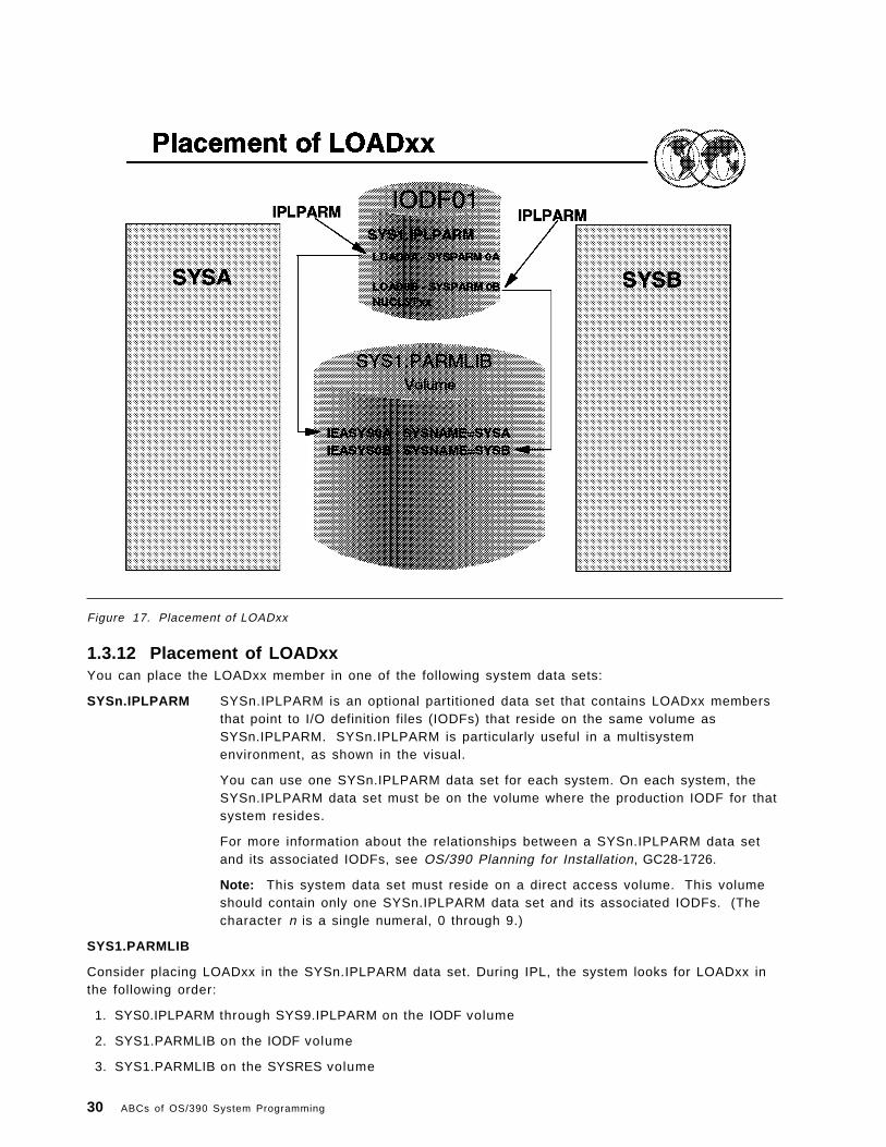
Figure 17. Placement of LOADxx
1.3.12 Placement of LOADxxYou can place the LOADxx member in one of the following system data sets:
SYSn.IPLPARM SYSn.IPLPARM is an optional partitioned data set that contains LOADxx membersthat point to I/O definition files (IODFs) that reside on the same volume asSYSn.IPLPARM. SYSn.IPLPARM is particularly useful in a multisystemenvironment, as shown in the visual.
You can use one SYSn.IPLPARM data set for each system. On each system, theSYSn.IPLPARM data set must be on the volume where the production IODF for thatsystem resides.
For more information about the relationships between a SYSn.IPLPARM data setand its associated IODFs, see OS/390 Planning for Installation, GC28-1726.
Note: This system data set must reside on a direct access volume. This volumeshould contain only one SYSn.IPLPARM data set and its associated IODFs. (Thecharacter n is a single numeral, 0 through 9.)
SYS1.PARMLIB
Consider placing LOADxx in the SYSn.IPLPARM data set. During IPL, the system looks for LOADxx inthe following order:
1. SYS0.IPLPARM through SYS9.IPLPARM on the IODF volume
2. SYS1.PARMLIB on the IODF volume
3. SYS1.PARMLIB on the SYSRES volume
30 ABCs of OS/390 System Programming

Do not create a SYSn.IPLPARM data set unless it contains the LOADxx member that is used toconfigure your system. When the system finds either SYSn.IPLPARM or SYS1.PARMLIB, it expects tofind a LOADxx member in the data set. If the LOADxx member specified on the LOAD parameter is notin the data set, the system loads a wait state.
The NUCLSTxx member must reside in the same data set as the LOADxx member. This member canreside in either SYS1.PARMLIB or SYSn.IPLPARM, depending on how the installation defined its I/Oconfiguration.
Member SYSCATLG of SYS1.NUCLEUS can contain a pointer to the master catalog. However, IBMrecommends that you use the SYSCAT statement of the LOADxx member of SYS1.PARMLIB orSYSn.IPLPARM to identify the master catalog.
Chapter 1. OS/390 Implementation and Maintenance 31

Figure 18. Controlling parmlib
1.3.13 How to control parmlibA parmlib concatenation allows you to have more flexibility in managing parmlib members andchanges to parmlib members. To control parmlib and ensure that it is manageable, you shouldconsider the following:
• Use the ability to have up to 10 installation-defined parmlib data sets to separate your parmlibmembers along organization or function lines and use appropriate RACF security for each data set.
• Include members with installation changes in one of the 10 installation-defined parmlib data sets toavoid having the member overlaid by IBM maintenance on SYS1.PARMLIB.
Note: If a member exists more than once within the parmlib concatenation, the first occurrence isused.
• Use an installation-defined parmlib data set to contain any parmlib members to be used on testsystems. They can be included in front of your standard parmlib concatenation without forcingchanges to the standard parmlib concatenation.
• Delete unsupported parameters and members. Because most components treat unsupportedparameters from previous releases as syntax errors, you should probably remove the oldparameters or build parmlib from scratch. This action will minimize the need for operatorresponses during an IPL. Then, you can save space by removing unsupported members.
• Use the parmlib members for the appropriate functions. For example, use COMMNDxx to containcommands useful at system initialization. Use IEACMDxx for IBM*-supplied commands. UseIEASLPxx for SLIP commands. See each member for further information.
• Update parmlib with new and replacement members, as you gain familiarity with the new release.
32 ABCs of OS/390 System Programming

• Keep track of which parameters are included in particular parmlib members. This bookkeeping isnecessary for two reasons: 1) The system doesn′ t keep track of parmlib members and theirparameters. 2) The default general parameter list IEASYS00 is always read by the system andmaster scheduler initialization.
The parameters in IEASYS00 can be overridden by the same parameters when they are specifiedin alternate general lists, such as IEASYS01, or IEASYS02. Then, certain parameters, such as FIX,APF, and MLPA, direct the system to particular specialized members (in this example, IEAFIXxx,and IEALPAxx).
The installation should keep records of which parameters and which values are in particularmembers, and which general members point to which particular specialized members(COMMNDxx, IEALPAxx, etc.). A grid or matrix for such bookkeeping is very helpful.
• Allocate sufficient space for parmlib. One way to estimate space is to count the number of80-character records in all members which are to be included in one parmlib data set and factor inthe blocksize of the data set. Then add a suitable growth factor (for example, 100− 3 0 0 percent) toallow for future growth of alternate members. To recapture space occupied by deleted members,use the compress function of IEBCOPY. However, should the data set run out of space, you maycopy the members to a larger data set, create a new LOADxx member in which you replace thePARMLIB statement for the full data set with a PARMLIB statement for the new larger data set, andthen issue a SETLOAD command to switch to the concatenation with the new data set.
• Ensure EXITxx and GTFPARM reside in SYS1.PARMLIB since they can only be accessed fromSYS1.PARMLIB.
• Decide which volume(s) and device(s) should hold the parmlib concatenation. The data set must becataloged, unless it resides on SYSRES or its volume serial number is included on the PARMLIBstatement in LOADxx. The data set could be placed on a slow or moderate speed device. Forinformation about the placement of parmlib data sets and the IODF data set, see OS/390 MVSSystem Data Sets Definition, GC28-1782.
• Use a security product (like RACF) to protect the data sets. The purpose is to preserve systemintegrity by protecting the appendage member (IEAAPP00) and the authorized program facilitymembers (IEAAPFxx and PROGxx) from user tampering.
1.3.13.1 General syntax rules for the creation of membersThe following general syntax rules apply to the creation of most parmlib members. Exceptions to theserules are described under specific members. The general rules are:
• Logical record size is 80 bytes.
• Blocksize must be a multiple of 80.
• Any columns between 1 and 71 may contain data.
• Statements are entered in uppercase characters.
• Suffix member identifiers can be any combination of A to Z and 0 to 9, though some memberidentifiers may allow other characters.
• Columns 72 through 80 are ignored.
• Continuation is indicated by a comma followed by one or more blanks after the last entry on arecord.
• Leading blanks are suppressed. A record therefore need not start at a particular column.
• Suffix member identifiers (such as LNK=A2) can be any alphanumeric combination.
• Comments are most often indicated by using /* and */ as the delimiters in columns 1− 7 1 , forexample:
/*comment*/
Chapter 1. OS/390 Implementation and Maintenance 33

However, some parmlib members require other methods. Check specific parmlib members forinformation about specifying comments.
34 ABCs of OS/390 System Programming

Figure 19. Parmlib commands
1.3.14 PARMLIB commandsThe use of commands enable installations to display the current logical parmlib, display general IPLinformation, and change the current logical parmlib settings.
The commands are:
• DISPLAY PARMLIB
This command displays the logical parmlib setup for the IPLed system. The output of thiscommand includes the parmlib data set name(s) and volser(s) that was defined by LOADxxPARMLIB statement(s), and if used, MASTER JCL IEFPARM DD statements. When the errorsoption on the command is used, the display shows any parmlibs that were defined in LOADxx butwere not found. This command is only valid before a SETLOAD command is issued. A sample outputis shown in the visual.
• DISPLAY IPLINFO
This command displays the general IPL information used by the system. The output includes thedate and time of the IPL, release level, LOADxx information, and what IEASYSxx and IEASYMxxparmlib members were used. A sample output of the command is shown in the visual.
Chapter 1. OS/390 Implementation and Maintenance 35

Figure 20. Parmlib commands
1.3.15 Parmlib commands
The following command (which is also shown in the visual) allows the installation to dynamicallychange a parmlib concatenation without having to IPL. A sample output of the SETLOAD command isshown in the visual.
SETLOAD R2,PARMLIB,DSN=SYS0.IPLPARM
36 ABCs of OS/390 System Programming

Figure 21. Parmlib commands output
1.3.16 Use of SETLOAD command
The sample output shown in visual is a result after the SETLOAD command was issued.
The second display shows the output of a DISPLAY PARMLIB command after an IPL had taken place usingLOADR2. PARMLIB statements were specified in LOADR2. Note the difference in the FLAGS columnshown in the visual.
The FLAGS describe how the parmlibs were specified:
• S denotes the LOADxx PARMLIB statement.
• D denotes the default (SYS1.PARMLIB).
Chapter 1. OS/390 Implementation and Maintenance 37

Figure 22. Catalogs
1.4 Catalogs
A catalog is a data set which contains information about other data sets. It provides users with theability to locate a data set by name, without knowing where the data set resides. By cataloging datasets, your users will need to know less about your storage setup. Thus, data can be moved from onedevice to another, without requiring a change in JCL DD statements which refer to an existing data set.
Cataloging data sets also simplifies backup and recovery procedures. Catalogs are the centralinformation point for VSAM data sets; all VSAM data sets must be cataloged. In addition, allSMS-managed data sets must be cataloged.
1.4.1 Using indirect catalog entries
Indirect cataloging, also known as indirect volume serial support, allows the system to dynamicallyresolve volume and device type information for non-VSAM, non-SMS managed data sets that reside onthe system residence (IPL) volume when accessed through the catalog. This allows you to change thevolume serial number or the device type of the system residence volume without also having torecatalog the non-VSAM data sets on that volume.
The extended indirect volume serial support that was introduced in OS/390 R3 allows catalog entries tobe resolved using system symbols defined in the IEASYMxx parmlib member, so that indirectreferences can be made to one or more logical extensions to the system residence volume. Therefore,
38 ABCs of OS/390 System Programming

you can have multiple levels of OS/390 data sets residing on multiple sets of volumes with differentnames and device types, and use them with the same master catalog.
Using indirect catalog entries, together with the indirect volume serial enhancements, allows you toshare the master catalog among multiple images that use different volumes with different names forthe system residence volumes and their extensions.
For more information on indirect volume serial support, see OS/390 MVS Initialization and TuningReference, SC28-1752.
1.4.2 Catalog management
Ensuring that your catalogs are effectively managed is therefore a crucial aspect of DASDmanagement. Some of the most common catalog management tasks that a system programmer mayhave are:
• Defining and maintaining the master catalog
• Defining the alias and user catalog
• Protecting the catalogs
• Cleaning up catalogs
• Backing up catalogs and performing catalog recovery
Chapter 1. OS/390 Implementation and Maintenance 39

Figure 23. Separating data from software
1.5 Separating data from software
When you separate your data from your system software, you eliminate many tasks that wouldotherwise need to be performed each time you upgrade or replace your system software. Oneeffective way to achieve this is to use dedicated pools of DASD volumes for each.
The kinds of data you should separate from OS/390 software are:
• Customization data, including most system control files
• Non-IBM software
• IBM non-OS/390 products, for example CICS and DB2
• User-defined exits
• User data
Your goal is to make it easier to replace the volumes that contain OS/390 software, which allows youto keep the other software and data you will need to use with OS/390 across migrations.
40 ABCs of OS/390 System Programming

Figure 24. Data set placement
1.6 Placing data sets on specific volumes
Some SYSRES volume types, such as the 3390-3, are not big enough to hold all the target libraries foran OS/390 system. Therefore, you have to move some data sets to SYSRES logical extension volumes(or overflow volumes). The considerations you should take into account for placing data sets onspecific volumes are:
• Your ability to use a system (or subsystem) replacement
• Data set and system availability
• System performance
• System cloning and servicing techniques
• Sysplex/multisystem operations
• Sharing data sets
• Backup and recovery
• Disaster recovery
Based on these considerations, you should determine which data sets to place on each volume basedon data set type, not based on element, feature, or product. There are basically five types of data sets,which each type can be placed on a separate (logical) volume:
• SMP/E global-shared data sets
Chapter 1. OS/390 Implementation and Maintenance 41

• Target libraries (TLIBs) for product sets
• Distribution libraries (DLIBs) for product sets
• Image-related data sets
• Cluster-related data sets
1.6.1 SMP/E global-shared data sets
These data sets should be placed on a volume shared by all systems in the complex that need SMP/Eglobal information. Sharing these data sets will provide an ease of backup and recovery. Therecommended types of data sets for this volume are:
• SMP/E global CSI
• SMPPTS
• SMP/E global logs (SMPLOG and SMPLOGA)
42 ABCs of OS/390 System Programming

Figure 25. The TLIBs volumes
1.6.2 Target libraries (TLIBs) for product sets
These target libraries spread across several volumes, from primary to secondary volumes:
• Primary target volume (TVOL1)
The TVOL1 is the first target library volume and the system residence (IPL) volume; it containsmany of the OS/390 target libraries. Make sure you leave enough free space to allow for futuregrowth. The recommended types of TVOL1 data sets are:
− Load libraries which are data sets containing load modules.
− Change migration libraries that are used during migration from one level of software toanother.
− Help libraries are data sets that contain help information.
− Panel libraries are data sets that contain ISPF panels.
− Message libraries are OS/390 libraries that contain ISPF messages and MMS source messages.
− Skeleton libraries are OS/390 libraries that contain ISPF skeletons.
− Table libraries are OS/390 libraries that contain ISPF tables.
− Fixed-block CLIST and EXEC libraries are data sets that contain CLIST and REXX EXECs.
− Data libraries are OS/390 libraries that contains data parts which include workstationinformation, header files, or other various types of data.
− SMP/E-managed PARMLIB which is the data set that is pointed to by the PARMLIB DDDEF,which will be used to store parmlib members supplied by products you install.
Chapter 1. OS/390 Implementation and Maintenance 43

− SMP/E-managed PROCLIB which is the data set that is pointed to by the PROCLIB DDDEF,which will be used to store JCL procedures supplied by products you install.
• Secondary target volumes (TVOL2 − TVOLn)
The TVOL2 through TVOLn are volumes used for data sets that do not fit on TVOL1. They are forthe OS/390 product set and the recommended types of TVOL2 through TVOLn data sets are:
− Fixed-block CLIST and EXEC libraries are used only if variable-block CLIST and EXEC librarieswere used on TVOL1.
− Sample and JCL libraries are OS/390 libraries that contain samples, header files, and JCL jobs.
− Source libraries are OS/390 libraries that contain source code.
− Macro libraries are OS/390 libraries that contain assembler macros, header files, and otherinformation identified in SMP/E as the element type MACRO.
− Workstation libraries which can be combined with the data libraries.
− Softcopy libraries into which SMP/E installs are OS/390 libraries that contain books,bookshelves, and bookindexes.
− Font and printing libraries are OS/390 libraries that contain fonts and data sets required forprinting.
− Flat files that SMP/E cannot manage include interface repositories and so forth, excludingbooks.
− SMP/E target CSI
− SMP/E target data sets including SMPLTS, SMPMTS, SMPSTS, and SMPSCDS.
− User catalog for the SMP/E target CSI and MVS-supplied data sets
• HFS target volume
The recommended types of data sets (filesystems) for this volume are:
− HFS data sets for OS/390 elements or features that install into an HFS.
− Any non-OS/390 HFS data set, except those containing customization data.
• Licensed product target volume
The libraries on this volume consist of the licensed product set that you might not have in asystem-replacement order and you want to keep separate. The recommended types of data setsfor this volume are:
− Licensed program target libraries.
− SMP/E target CSI.
− SMP/E target data sets: SMPLTS, SMPMTS, SMPSTS, and SMPSCDS.
− User catalog where all the licensed program libraries and the SMP/E target CSI are cataloged.
• Vendor product target volume
The libraries on this volume consist of the vendor product set that you might not have in asystem-replacement order and you want to keep separate. The recommended types of data setsfor this volume are:
− Vendor target libraries.
− SMP/E target CSI.
− SMP/E target data sets: SMPLTS, SMPMTS, SMPSTS, and SMPSCDS,
− User catalog where all the vendor product target libraries including the SMP/E target CSI arecataloged.
44 ABCs of OS/390 System Programming

• Subsystem target volume
The libraries on this volume consist of the subsystem product sets (for example, CISCS, DB2, IMS,or NCP). The recommended types of data sets for this volume are:
− Subsystem target libraries.
− Alternate subsystem SMP/E global CSI, if applicable.
− SMP/E target CSI.
− SMP/E target data sets: SMPLTS, SMPMTS, SMPSTS, and SMPSCDS.
− User catalog where the subsystem targets libraries including SMP/E CSIs are cataloged.
Chapter 1. OS/390 Implementation and Maintenance 45
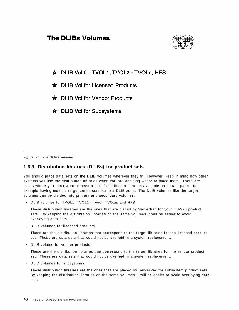
Figure 26. The DLIBs volumes
1.6.3 Distribution libraries (DLIBs) for product sets
You should place data sets on the DLIB volumes wherever they fit. However, keep in mind how othersystems will use the distribution libraries when you are deciding where to place them. There arecases where you don′ t want or need a set of distribution libraries available on certain packs, forexample having multiple target zones connect to a DLIB zone. The DLIB volumes like the targetvolumes can be divided into primary and secondary volumes:
• DLIB volumes for TVOL1, TVOL2 through TVOLn, and HFS
These distribution libraries are the ones that are placed by ServerPac for your OS/390 productsets. By keeping the distribution libraries on the same volumes it will be easier to avoidoverlaying data sets.
• DLIB volumes for licensed products
These are the distribution libraries that correspond to the target libraries for the licensed productset. These are data sets that would not be overlaid in a system replacement.
• DLIB volume for vendor products
These are the distribution libraries that correspond to the target libraries for the vendor productset. These are data sets that would not be overlaid in a system replacement.
• DLIB volumes for subsystems
These distribution libraries are the ones that are placed by ServerPac for subsystem product sets.By keeping the distribution libraries on the same volumes it will be easier to avoid overlaying datasets.
46 ABCs of OS/390 System Programming

Figure 27. The image-related volumes
1.6.4 Image-related data sets
These data sets contain non-shareable system image information. Although the recommendation isthat they be put on separate volumes, if DASD space is scarce you can combine them at the expenseof performance or availability, or both. The image-related data sets are placed in the followingrecommended volumes:
• Page data sets volume 1
The recommended types of data sets for this volume are:
− PLPA (one-cylinder allocation)
− COMMON
Note: Unless your system is central-storage constrained, and has significant PLPA pagingactivity, there is little or no performance impact to combining the PLPA and COMMON pagedata sets. The PLPA data set should be allocated first, as a one-cylinder data set, with theCOMMON data set allocated second, immediately following the PLPA data set on the samevolume. The size of the COMMON data set should be large enough to contain both PLPA andCOMMOND pages.
This causes the vast majority of PLPA pages to be written to the COMMOND page data setduring IPL. This allows the operating system to use the chained CCWs within a single data setand improves performance when both data sets are on the same volume.
The message (ILR005E PLPA PAGE DATA SET FULL, OVERFLOWING TO COMMON DATA SET)during IPL can be ignored when the PLPA and COMMON page data sets are on the samevolume.
• Page data set volumes 2 to n
Chapter 1. OS/390 Implementation and Maintenance 47
The recommended types of data sets for these volumes are:
− Local
− SMF
− RMF reporting
− STGINDEX data set (if used)
− Image-related LOGREC data set (if used)
• HFS customization volume
This is an installation maintained volume that contain data sets that will not be overlaid by systemreplacement. This volume is separate from the HFS target volume because it containsunshareable HFS files that will generally need to be mounted MODE(RDWR). The recommendedtypes of data sets for this volume are:
− HFS data sets that must be in write mode (for instance, /tmp, /etc, /dev, /u) and containcustomized information.
− User catalog where the HFS data sets are cataloged.
48 ABCs of OS/390 System Programming

Figure 28. The cluster-related volumes
1.6.5 Cluster-related data sets
These are shareable data sets used in a multisystem environment. Cluster-related data sets shoulduse system symbolics in their names for easier maintainability. While all cluster-related data sets canbe combined on the same volume, it is usually preferable to separate certain data sets from others forperformance or availability reasons. You can group the cluster-related data sets into the followingvolumes:
• Master catalog volume
The recommended types of data sets for this volume are:
− Master Catalog
− BROADCAST data set
− Customer parmlib concatenation (not the SMP/E DDDEFed PARMLIB)
− Customer proclib concatenation (not the SMP/E DDDEFed PROCLIB)
− UADS data set (if used)
− VTAMLST data set
− SMS control data sets (ACDS, SCDS, and COMMDS), HSM, RMM, and so forth
− APPC VSAM data set
− System control files (TCPI/P configuration and so forth)
− Primary RACF database
− IODF data set
Chapter 1. OS/390 Implementation and Maintenance 49

− SYS0.IPLPARM
− UCATs
− SYS1.DDIR sysplex dump directory data set
− DAE data set
• JES checkpoint volume
For maximum performance and reduced contention, place the primary JES checkpoint data set onits own dedicated volume. The JES checkpoint primary data set may be on a Coupling Facility.
• JES spool volume
You can place the JES duplex checkpoint data set together with the JES spool to reduce I/O andimprove performance. Having the duplex data set on the same volume as one of the JES spooldata sets will take advantage of the fact that JES checks, during every write to the JES spool,whether a checkpoint data set resides on the same volume.
• Sysplex-related volume 1
The recommended types of data sets for this volume are:
− SYSPLEX primary
− CFRM alternate
− ARM primary
− WLM primary
− LOGR primary
Note: The CFRM primary and SYSPLEX primary should be on different volumes attached todifferent control units. All other primary couple data sets can reside on the same volume, andall other alternate couple data sets can reside on a different volume.
• Sysplex-related volume 2
The recommended types of data sets for this volume are:
− SYSPLEX alternate
− CFRM primary
− ARM alternate
− WLM alternate
− LOGR alternate
− Secondary RACF database
• Softcopy volume
This volume holds softcopy books and related data sets. The recommended types of data sets forthis volume are:
− Books
− Bookshelves
− Bookindexes
Many volumes on your system will contain data sets that are not supplied by ServerPac. Keeping suchvolumes separate from those that ServerPac will replace, or that you will replace when migrating thenew system to other system images, makes it easier to prevent overlaying data sets that you want tokeep.
For more information on data sets placement, see OS/390 Planning for Installation, GC28-1726.
50 ABCs of OS/390 System Programming

Figure 29. Naming conventions for data sets
1.7 Choosing a naming convention for data sets
Choosing the right naming conventions for system software data sets can save you considerable timeduring installation and migration.
Some data sets are associated with only one system in a multisystem environment. Choose names forthese data sets that reflect the name of the specific system. Names of system operational data sets,such as page and swap data sets, should include the system name. You can accomplish this using theIBM-supplied system symbol SC68.
Using symbolic substitution involves carefully establishing naming conventions for data sets, such asparmlib and proclib members, system images, HCD definition, and so forth. Remember that once yoursystem goes into production with a set of naming conventions, you cannot easily change them.
IBM has been removing the level-dependent qualifier (such as V1R1M0) from default data set namesfor OS/390 elements in order to ease your migration to a new OS/390 release. This preserves much ofyour existing JCL, system procedures, parmlib and other system control file contents, and securitysystem definition across upgrades, saving you time and reducing the opportunity for error becauseupdates will be limited to just the data sets in which the low-level qualifiers were changed.
Chapter 1. OS/390 Implementation and Maintenance 51

Figure 30. DASD space util ization and performance
1.8 DASD space utilization and performance
The space required by system software data sets, except for PDSE data sets, is affected by the blocksizes you choose for those data sets. Generally, data sets with larger block sizes use less space tostore the same data than those with smaller block sizes.
The exception to this general rule are fixed block (FB) record format data sets. They should not beallocated with block sizes larger than half the track length of the DASD they are allocated on. Doing sowill cause considerable DASD space to be wasted, because current DASD track lengths are less thantwice the maximum block size of 32760 bytes.
Generally, system-determined block sizes (SDB) are the best choice for block size for fixed block (FB),variable blocked (VB), and variable block spanned (VBS) record format data sets. You should use SDBfor all system software data sets with these record formats except those for which IBM specificallyrecommends other block sizes. One way to do this is by specifying BLKSIZE=0 in the DCB parameterof a DD statement when allocating new data sets using JCL. For more information, see OS/390 MVSJCL Reference, GC28-1757.
Data sets with undefined (U) record formats do not follow the same rules as those with other recordformats. In particular, most load libraries in partitioned data sets (not PDSEs) will require less spaceand offer better performance at increasing block sizes right up to the block size limit of 32760 bytes.The reason is because the program management binder, linkage editor, and IEBCOPY′s COPYMODcommand use the data set block size only to set the maximum block length they will use.
Allocate all load libraries using a block size of 32760 bytes unless you plan to move your systemsoftware data sets from the device types on which they were originally allocated to device types with
52 ABCs of OS/390 System Programming

shorter track lengths, or plan to move them between device types having different track lengths withoutusing IEBCOPY COPYMOD.
For most efficient use of DASD, it is recommended that you allocate OS/390 data sets using thefollowing block sizes:
• Use the SDB for most of non-RECFM U data sets.
• For RECFM U data sets, use BLKSIZE=32760.
• For UADS data sets for TSO/E, use the same block size you currently use to allocate a new one.Do not use SDB, as this will result in very poor DASD space utilization.
• You should not use the SDB for font libraries too. The correct block size for the font libraries is12288.
For more information on the usage of SDB, see DFSMS/MVS Using Data Sets, SC26-4922.
Chapter 1. OS/390 Implementation and Maintenance 53

Figure 31. System data sets
1.9 System data sets
Before you install OS/390, you must select and define the system data sets that you need.
Before you include components from the distribution libraries (DLIBs) and user-defined data sets in thesystem, use JCL and access method services to define the system data sets.
This visual contains some of the common system data sets. For a complete list of system data sets,see OS/390 MVS System Data Sets Definition, GC28-1782.
A description of the data sets can be found in A.3, “System data sets” on page 291.
54 ABCs of OS/390 System Programming

Figure 32. System administration
1.10 System administration tasks
Once you have the system up and running, you will spend most of your time maintaining the well-beingof the system at the same time providing technical support to your users. The following sections inthis chapter discuss some of the administrative tasks performed by a system programmer.
Chapter 1. OS/390 Implementation and Maintenance 55

Figure 33. User administration
1.11 User administration
A system is never complete without users using it. Most of the time, you will find yourself having toperform certain user administration tasks. The next few sections provide examples of typicalprocesses used when adding, deleting, or administrating users.
Some of the common user administrative tasks discussed in this section are:
• Add new users
• Create RACF profiles for new users
• Modify RACF profiles for existing users
• Reset password
• Delete users and their RACF profiles
56 ABCs of OS/390 System Programming

Figure 34. DASD administration
1.12 DASD administration
On a larger installation, you might have a team of storage administrators to take care of all DASDadministration tasks and you as a system programmer may only be required to help with obscureproblems and exit routines. In that environment, you may never have to deal with the hardware side ofDASD management, other than modifying IODF and IOCDS using HCD. On the other hand, yourinstallation may be of a smaller scale that doesn ′ t warrant having a dedicated team of storageadministrators and so you may have to take on far more of these roles.
1.12.1 DASD management
As a system programmer taking on the additional responsibility of a storage administrator, you mighthave to handle these aspects of DASD management:
• Adding new DASD devices and volumes to your system
• Implementing SMS
• Effectively managing catalogs
• Dealing with DASD problems
Chapter 1. OS/390 Implementation and Maintenance 57

Figure 35. Adding a new DASD volume
1.12.2 How to add additional DASD volumes
The following list outlines the steps of making a new DASD volume available to your system:
1. Physically connect the new device to the storage controller, which is connected to the systemthrough an available channel. Normally, this task is performed by an IBM Customer Engineer whotakes care of all the hardware installation.
2. Using HCD, you have to update the IODF and IOCDS to include the new devices. You might wantto define the device as belonging to one or more eligible device tables defined in your currentIODF, so that data sets can be allocated on it using the UNIT parameter with the associatedesoteric device name. For more information on how to use HCD, see OS/390 HardwareConfiguration Definition User′s Guide, SC28-1848.
3. Using ICKDSF, initialize the new volume with a volume serial label, a volume table of contents(VTOC), and a VTOC index. For more information on ICKDSF, see ICKDSF R16 Refresh, User′sGuide, GC35-0033.
4. Vary the device online, and issue an appropriate MOUNT command, or re-IPL MVS to cause the newvolume to be mounted according to the VATLST entries.
A disk volume is mounted with one of the following use attributes except DFSMS-managedvolumes:
• PRIVATE
58 ABCs of OS/390 System Programming
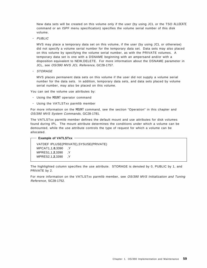
New data sets will be created on this volume only if the user (by using JCL or the TSO ALLOCATEcommand or an ISPF menu specification) specifies the volume serial number of this diskvolume.
• PUBLIC
MVS may place a temporary data set on this volume, if the user (by using JCL or otherwise)did not specify a volume serial number for the temporary data set. Data sets may also placedon this volume by specifying the volume serial number, as with the PRIVATE volumes. Atemporary data set is one with a DSNAME beginning with an ampersand and/or with adisposition equivalent to NEW,DELETE. For more information about the DSNAME parameter inJCL, see OS/390 MVS JCL Reference, GC28-1757.
• STORAGE
MVS places permanent data sets on this volume if the user did not supply a volume serialnumber for the data sets. In addition, temporary data sets, and data sets placed by volumeserial number, may also be placed on this volume.
You can set the volume use attributes by:
• Using the MOUNT operator command
• Using the VATLSTxx parmlib member
For more information on the MOUNT command, see the section “Operation” in this chapter andOS/390 MVS System Commands, GC28-1781.
The VATLSTxx parmlib member defines the default mount and use attributes for disk volumesfound during IPL. The mount attribute determines the conditions under which a volume can bedemounted, while the use attribute controls the type of request for which a volume can beallocated.
Example of VATLSTxx
VATDEF IPLUSE(PRIVATE),SYSUSE(PRIVATE)MPCAT1,1,0,3390 ,YMPRES1,1,2,3390 ,YMPRES2,1,2,3390 ,Y
The highlighted column specifies the use attribute. STORAGE is denoted by 0, PUBLIC by 1, andPRIVATE by 2.
For more information on the VATLSTxx parmlib member, see OS/390 MVS Initialization and TuningReference, SC28-1752.
Chapter 1. OS/390 Implementation and Maintenance 59

Figure 36. Implementing SMS
1.12.3 Implementing System Managed Storage (SMS)
After you have added the new volumes to the system, you should not make all the volumes availableto the users and allow them to use them as they wish. With no restriction on which volumes they canuse or how much space they can allocate, your new disk volumes will be filled up fairly quickly. Youcould spend most of your time providing a new supply of disk volumes for other essential data,tracking down the owner of each data set to establish their importance, and trying to negotiate forspace reduction.
One way to solve this problem is to allocate individual volumes to each application, usage type, orgroup of users. Each of these volumes are mounted PRIVATE and allocation can be done by specifyingthe volume serial number. However, this method of control has some disadvantages:
• The requirement of specifying a volume serial number in JCL during allocation can lead toinflexibility; for example, a space allocation on one volume might fail even though there is lot ofspace on other volumes available to the user.
• It is time-consuming and difficult to change the volumes available to the user as this requireschanging the hard-coded volume serial number in the JCL.
All these problems can be avoided by implementing System Managed Storage (SMS). It uses softwareto help you to automate the management of storage, for example data security, data set placement,data set migration and recall, data set backup, data set recovery and deletion, to ensure that currentdata is available when needed and obsolete data is removed from storage. Some of the benefits ofsystem managed storage are:
60 ABCs of OS/390 System Programming

• Simplified data allocation• Ensured data integrity on new allocation• Improved allocation control
Chapter 1. OS/390 Implementation and Maintenance 61

Figure 37. Handling DASD problems
1.12.4 How to deal with DASD problems
The most common DASD problem that you will encounter in your role as a system programmer is I/Oerror.
The normal error handling processing by the storage subsystem (that is, the storage control and itsattached storage devices) and by the operating system, OS/390, includes various functions thatrecognize errors and recover from them whenever possible.
The storage subsystem performs the following functions:
• Adds ECC (error checking and correction) information to each field of a record when it is written.
• Detects error in reading data, in performing control operations, in functioning of the hardware, andin programming.
• Retries I/O operations for certain error conditions.
• Assembles usage and error information in the form of sense information.
• Maintains counts of disk storage errors.
• Performs ECC correction activity or sends the ECC data to the operating system for correction.
The operating system, MVS, provides standard error recovery procedures to handle errors detected bythe storage subsystem:
• Implements recovery actions
62 ABCs of OS/390 System Programming
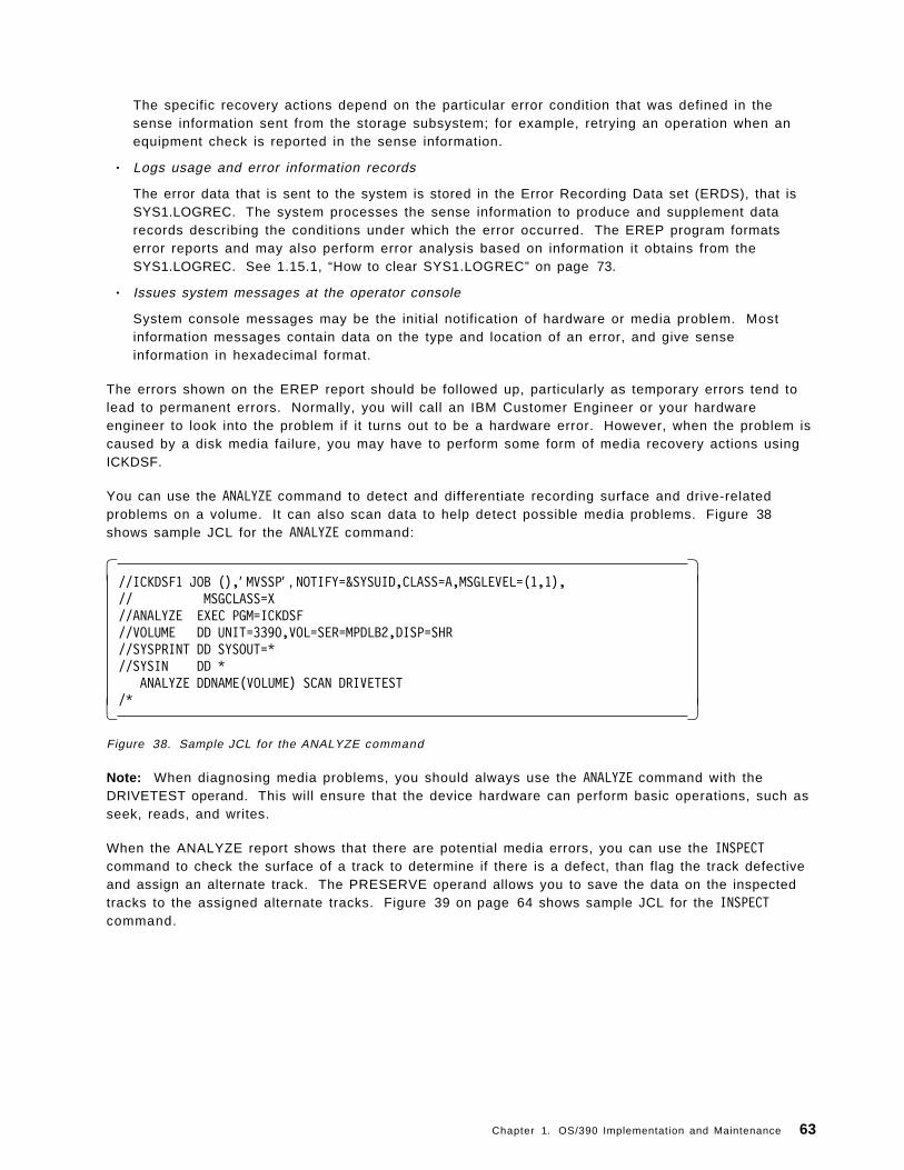
The specific recovery actions depend on the particular error condition that was defined in thesense information sent from the storage subsystem; for example, retrying an operation when anequipment check is reported in the sense information.
• Logs usage and error information records
The error data that is sent to the system is stored in the Error Recording Data set (ERDS), that isSYS1.LOGREC. The system processes the sense information to produce and supplement datarecords describing the conditions under which the error occurred. The EREP program formatserror reports and may also perform error analysis based on information it obtains from theSYS1.LOGREC. See 1.15.1, “How to clear SYS1.LOGREC” on page 73.
• Issues system messages at the operator console
System console messages may be the initial notification of hardware or media problem. Mostinformation messages contain data on the type and location of an error, and give senseinformation in hexadecimal format.
The errors shown on the EREP report should be followed up, particularly as temporary errors tend tolead to permanent errors. Normally, you will call an IBM Customer Engineer or your hardwareengineer to look into the problem if it turns out to be a hardware error. However, when the problem iscaused by a disk media failure, you may have to perform some form of media recovery actions usingICKDSF.
You can use the ANALYZE command to detect and differentiate recording surface and drive-relatedproblems on a volume. It can also scan data to help detect possible media problems. Figure 38shows sample JCL for the ANALYZE command:
� �//ICKDSF1 JOB (),′ MVSSP′ , NOTIFY=&SYSUID,CLASS=A,MSGLEVEL=(1,1),// MSGCLASS=X//ANALYZE EXEC PGM=ICKDSF//VOLUME DD UNIT=3390,VOL=SER=MPDLB2,DISP=SHR//SYSPRINT DD SYSOUT=*//SYSIN DD *
ANALYZE DDNAME(VOLUME) SCAN DRIVETEST/*� �
Figure 38. Sample JCL for the ANALYZE command
Note: When diagnosing media problems, you should always use the ANALYZE command with theDRIVETEST operand. This will ensure that the device hardware can perform basic operations, such asseek, reads, and writes.
When the ANALYZE report shows that there are potential media errors, you can use the INSPECTcommand to check the surface of a track to determine if there is a defect, than flag the track defectiveand assign an alternate track. The PRESERVE operand allows you to save the data on the inspectedtracks to the assigned alternate tracks. Figure 39 on page 64 shows sample JCL for the INSPECTcommand.
Chapter 1. OS/390 Implementation and Maintenance 63

� �//ICKDSF2 JOB (),′ MVSSP′ , NOTIFY=&SYSUID,CLASS=A,MSGLEVEL=(1,1),// MSGCLASS=X//INSPECT EXEC PGM=ICKDSF//VOLUME DD UNIT=3390,VOL=SER=MPDLB2,DISP=SHR//SYSPRINT DD SYSOUT=*//SYSIN DD *
INSPECT DDNAME(VOLUME) ASSIGN CHECK PRESERVE/*� �
Figure 39. Sample JCL for the INSPECT command
For more information on ANALYZE and INSPECT, and other ICKDSF commands, see ICKDSF R16 Refresh,User′s Guide, GC35-0033.
64 ABCs of OS/390 System Programming

Figure 40. System data housekeeping
1.13 System data housekeeping
To help you to manage your system properly, MVS generates lots of useful management data ofvarious types and stores them in system data sets. There are four types of system data which you willhave to deal with:
• SMF records
The SMF records contain a variety of information that enables you to produce many types ofanalysis reports and summary reports so that you can evaluate changes in configuration, workload,or job scheduling procedures by studying the trends in the data.
You can also use SMF data to determine system resources wasted because of problems such asinefficient operational procedures or programming conventions
• LOGREC data
The data from the LOGREC data set contains statistical data about machine failures (processorfailures, I/O device errors, channel errors). It also contains records for program error recording,missing interrupt information, and dynamic device reconfiguration (DDR) routines.
• SYSLOG data
This data set resides in JES2′s spool space. It can be used by application and systemprogrammers to record communications about problem programs and system functions. It alsocontains a record of console messages and operator commands for audit and diagnosis purposes.
• System DUMP data sets
Chapter 1. OS/390 Implementation and Maintenance 65

These system data sets are sequential data sets which contain system dumps, that record areas ofvirtual storage in case of system task failures. For more information on SYS1.DUMPx data sets, seeChapter 9, “Debugging OS/390.”
66 ABCs of OS/390 System Programming

Figure 41. SMF data
1.14 How to collect SMF data
To record SMF data, you have to allocate direct access space and catalog the SMF data sets. Youshould allocate at least two data sets for SMF use (with at least one on a high-performance device).
Notes:
1. A high-performance device is needed because, if the I/O rate is too slow, data wil l have to bebuffered. The buffers will eventually fill up, which could result in lost data.
2. You also have to consider the following factors when determining which device type whenallocating SMF data sets:
• Your system configuration
• The amount of SMF data to be written
• The size of SMF buffers (the control interval size)
• Your installation ′s report program requirement
The naming convention used for SMF data sets is SYS1.MANx, such as SYS1.MAN1, SYS1.MAN2,SYS1.MAN3, and so forth. You can use the sample JCL shown in Figure 42 on page 68 to allocatenew SMF data sets:
Chapter 1. OS/390 Implementation and Maintenance 67

� �//DEFINE JOB (),′ MVSSP′ , NOTIFY=&SYSUID,CLASS=A,MSGLEVEL=(1,1),// MSGCLASS=X//STEP1 EXEC PGM=IDCAMS//SYSPRINT DD SYSOUT=*//SYSIN DD *
DEFINE CLUSTER( -CONTROLINTERVALSIZE(4096) -CYLINDERS(40) -NAME(SYS1.MAN1) -NONINDEXED -RECORDSIZE(4086,32767) -REUSE -SHAREOPTIONS(2) -SPANNED -SPEED -VOLUME(MTCAT1) ) -
DATA( -NAME(SYS1.MAN1.DATA) )
/*� �Figure 42. Sample JCL to allocate new SMF data sets
68 ABCs of OS/390 System Programming

Figure 43. SMFPRMxx parmlib member
1.14.1 SMFPRMxx parmlib member
Once you have allocated all the required SMF data sets, you have to update the SMFPRMxx inSYS1.PARMLIB to reflect the new SMF data sets. In order to enable SMF recording, make sure thatthe first parameter in SMPFPRMxx is set to ACTIVE as shown in the visual.
To activate the new changes to SMF parameters, you can use the SET command to make themeffective (assuming that you have added SYS1.MAN3 to SMFPRM00) as shown in Figure 44 onpage 70.
Chapter 1. OS/390 Implementation and Maintenance 69

� �SET SMF=00IEF196I IEF237I 0800 ALLOCATED TO IEFPARMIEE252I MEMBER SMFPRM00 FOUND IN SYS1.PARMLIBIEF196I IEF237I 0802 ALLOCATED TO SYS00004IEE966I SYS1.MAN3 IS BEING FORMATTED�1�IEF196I IEF285I SYS1.PARMLIB KEPTIEF196I IEF285I VOL SER NOS= MPRES1.IEE949I 03.01.03 SMF DATA SETS 097
NAME VOLSER SIZE(BLKS) %FULL STATUS�2�P-SYS1.MAN1 MPCAT1 7200 9 ACTIVE
S-SYS1.MAN2 MPCAT1 1800 0 ALTERNATES-SYS1.MAN3 MPCAT1 1800 0 ALTERNATE
IEE536I SMF VALUE 00 NOW IN EFFECT� �Figure 44. Activating the changes to the SMF parameters
�1�SMF found that SYS1.MAN3 has not been formatted. The formatting is now taking place.
�2�The name of the SMF data set preceded by a P indicates that it is the primary SMF data set. If thename is preceded by a S, the data set is a secondary SMF data set.
1.14.1.1 Types of SMF records
You can control which SMF record types are recorded by using the SYS parameter in the SMFPRMxxparmlib member. You can specify SYS(TYPE(0:255)) to record all SMF records. However, this cancreate considerable overhead and fill up the SMF data sets very quickly. The default SYS parameter isSYS(NOTYPE(14:19,62:69,99). This collects all SMF records except the following:
• Record type 14 is written for input non-VSAM direct access, tape data sets, or VIO data sets.
• Record type 15 is written for output non-VSAM direct access, or VIO data sets.
• Record type 16 is written to record information about events and operations of the sorting program.
• Record type 17 is written when a non-temporary data set or temporary data set is scratch.
• Record type 18 is written when a non-VSAM data set is renamed.
• Record type 19 is written for a list of online devices with specific IPL time frame.
• Record types 62 to 69 are written for various VSAM data sets and catalog activities.
• Record type 99 is written by the System Resource Manager (SRM) component when running ingoal mode.
For more information about the rest of SMF record types, see OS/390 V2R7.0 MVS System ManagementFacilities (SMF), GC28-1783.
70 ABCs of OS/390 System Programming

Figure 45. Dumping SMF data
1.14.2 Dumping SMF data
When the current recording data set cannot accommodate any more records, the SMF writer routineautomatically switches recording from the active SMF data set to an empty SMF data set and issuesthe following message regarding the full data set:
*IEE362A SMF ENTER DUMP FOR SYS1.MAN1 ON MPCAT1
You can use the sample JCL shown in the visual to dump the SMF data to a user data set and clearthe SMF data set for reuse.
OPTIONS(ALL) indicates that the input data set specified in the DUMPIN DD statement is to be copied,then reset and preformatted.
Note: The output data set in the DUMPOUT DD statement should be large enough to hold one SMFdata set, the minimum requirement is 30 cylinders.
Alternatively, you may code an IEFU29 exit to submit the job. The IEFU29 exit is invoked (if activated inSMFPRMxx) whenever an SMF data set switch occurs. For more information about the IEFU29 dumpexit, see OS/390 V2R7.0 MVS Installation Exits, SC28-1753.
Chapter 1. OS/390 Implementation and Maintenance 71

Figure 46. LOGREC data
1.15 How to create SYS1.LOGREC
When an error occurs, the system records information about the error in the LOGREC data set. Theinformation provides you with a history of all hardware failures, selected software errors, and selectedsystem conditions. You can use the Environment Record, Editing, and Printing (EREP) program to:
• Print reports about the system records
• Determine the history of the system
• Learn about a particular error
Before the system can record all this information, you must first allocate the LOGREC data set andinitialize it.
Note: Whenever you allocate or reallocate the LOGREC data set, the newly allocated data set will notbe used until you initialize it and IPL the system on which it is to be used.
You can use the sample JCL shown in Figure 47 on page 73 to accomplish the task.
72 ABCs of OS/390 System Programming

� �//LOGREC JOB (),′ MVSSP′ , NOTIFY=&SYSUID,CLASS=A,MSGLEVEL=(1,1),// MSGCLASS=X//***********************************************//* CREATE A NEW LOGREC DATASET AND INITIALIZE IT//***********************************************//STEP1 EXEC PGM=IFCDIP00,COND=(4000,LT)//SERERDS DD UNIT=SYSDA,VOL=SER=MPRES1,SPACE=(CYL,3,,CONTIG),// DSN=SYS1.LOGREC,DISP=(,CATLG)//SYSPRINT DD SYSOUT=*� �
Figure 47. Sample JCL to create and initialize a new LOGREC data set
Note: The IBM-supplied default name for the LOGREC data set is SYS1.LOGREC. To change theLOGREC data set name known to the system, use the LOGREC parameter of the IEASYSxx parmlibmember.
If you use the default name SYS1.LOGREC in a multisystem environment take care to ensure that theLOGREC data set is uniquely specified with the volume-serial. This will prevent the initialization ofanother system′s LOGREC data set in the event that IFCDIP00 is run on a different system.
1.15.1 How to clear SYS1.LOGREC
The LOGREC data set will eventually become full, the same as the SMF data set, and consolemessages appear requesting the operator to take action. Therefore, this data set needs to be clearedso that it can be reused. The process is a little different because there is only one LOGREC data set.
As a system programmer, you have to set up a process to clear the LOGREC data set when thefollowing message appears:
IFB080E LOGREC DATA SET NEW FULL, DSN=SYS1.LOGREC
This is issued when the LOGREC data set becomes 90 percent full; if action is not taken and LOGRECfills up completely, the following message is issued which requires prompt action:
IFB081I LOGREC DTA SET IS FULL, hh.mm.ss, DSN=SYS1.LOGREC
At this stage, if you do not take any action, the system continues processing, but further error recordswill be lost. You can use the sample JCL shown in Figure 48 to clear your LOGREC data set.
� �//CLRLOG JOB (),′ MVSSP′ , NOTIFY=&SYSUID,CLASS=A,MSGLEVEL=(1,1),// MSGCLASS=X//STEP EXEC PGM=IFCEREP1,PARM=′ CARD′//SERLOG DD DSN=SYS1.LOGREC,DISP=OLD//ACCDEV DD DSN=SYS1.LOGREC.TEMPSTOR,DISP=MOD//TOURIST DD SYSOUT=*//EREPPT DD SYSOUT=*//SYSIN DD DUMMY
SYSUMACC=YZERO=Y
/*� �Figure 48. Sample JCL to clear the LOGREC data set
Chapter 1. OS/390 Implementation and Maintenance 73

The job will copy the LOGREC data set to the data set specified in the DDNAME ACCDEV, print a briefsummary of LOGREC data, and then clear the data set. For more information about the rest of theparameters, see EREP V3R5 Reference, GC35-0152.
74 ABCs of OS/390 System Programming

Figure 49. The SYSLOG data set
1.16 The SYSLOG
The SYSLOG on the MVS system actually consists of two separate logs: the system log and thehardcopy log.
The hardcopy log is a record of all system message traffic:
• Messages to and from all consoles
• Commands and replies entered by the operator
In a JES3 system, the hardcopy log is always written to the SYSLOG. While in a JES2 system, you canchoose to have the hardcopy log written to the SYSLOG or to a console printer. You can do this byspecifying the HARDCOPY statement in the CONSOLxx parmlib member as shown in Figure 50.
� �HARDCOPY DEVNUM(SYSLOG,OPERLOG)�1�
ROUTCODE(ALL)CMDLEVEL(CMDS)UD(Y)HCFORMAT(CENTURY)� �
Figure 50. Example of HARDCOPY statement in CONSOLxx
Chapter 1. OS/390 Implementation and Maintenance 75

�1�SYSLOG indicates that the system log is to be the hardcopy medium, while OPERLOG indicates thatthe operations log will be activated and will receive the hardcopy message set.
Note: The system defaults to SYSLOG as the hardcopy medium in any of the following cases:
• You do not code a HARDCOPY statement.
• You specify an unusable hardcopy console.
• You specify OPERLOG alone but the operations log is unusable.
For more information on the HARDCOPY statement, see OS/390 MVS Initialization and TuningReference, SC28-1752.
The SYSLOG is a SYSOUT data set provided by the job entry subsystem (either JES2 or JES3).SYSOUT data sets are output spool data sets on direct access storage devices (DASD). An installationshould print the SYSLOG periodically to check for problems. The SYSLOG consists of the following:
• All messages issued through Write To Log (WTL) macros.
• All messages entered by the LOG operator commands.
• Usually, the hardcopy log.
• Any messages routed to the SYSLOG from any system component or program.
You can limit the maximum number of WTLs (messages) allowed for the SYSLOG at IPL time by usingthe LOGLMT parameter in the IEASYSxx parmlib member. The value is used by log processing todetermine when the SYSLOG should be be scheduled for SYSOUT processing by JES. When this valueis reached, the log processing:
• Issues a simulated WRITELOG command to close and free the current SYSLOG.
• Releases the closed SYSLOG to the printer queue whose output class is specified by the LOGCLSparameter of the IEASYSxx parmlib member.
• Allocates and opens a new SYSLOG.
Example of LOGLMT and LOGCLS in IEASYSxx
LOGCLS=L, LOGLMT=99999,
In the example, the SYSLOG is scheduled for SYSOUT processing on output class L when 99,999 WTLshave been issued. For more information on LOGLMT and LOGCLS, see OS/390 MVS Initialization andTuning Reference, SC28-1752.
Remember that the SYSLOG provides a permanent, consolidated record of all console messages andcommands, that is, the event log of the system. Thus, you might want to review the SYSLOG at a laterdate when you are doing problem diagnosis. Instead of having the SYSLOG written to the outputqueue after a certain number of WTLs, you should set up a procedure to housekeep the SYSLOG dataset depending on your installation′s requirement.
You can perform your housekeeping as follows:
1. Set up a procedure to have the system operator issue the WRITELOG. command to close andallocate a new SYSLOG at the end of each processing day. For example, WRITELOG H.
Note: Class H is not a default printer class so the SYSLOG data set is kept in the spool.
2. At the end of the week, you wil l have seven SYSLOG data sets in the spool. You can now decideto offload the SYSLOG to an MVS data set or route it to a printer for a hardcopy printout.
3. It′s really not necessary to keep SYSLOG data sets for more than a week, so if you keep a week ′sworth of SYSLOG data sets, you should not have a problem.
76 ABCs of OS/390 System Programming

Figure 51. Other administration tasks
1.17 Other administration tasks
In this section, we discuss some other administrative tasks and techniques:
• How to work with MIH
• How to add page data sets
• How to change TSO timeout
• How to add spool volumes
• How to delete spool volumes
• How to verify system configuration
• How to view SYSOUT using ISPF
• How to change your TSO profile
• How to back up and restore OS/390
Chapter 1. OS/390 Implementation and Maintenance 77

Figure 52. Working with MIH
1.17.1 How to work with Missing Interrupt Handler (MIH)
When OS/390 sends channel commands to a control unit, it waits for a response. If no response isreceived after a certain amount of time, a missing interrupt situation exists. The following conditionsqualify as missing interrupts if the specified time interval has elapsed:
• Primary status interrupt pending
• Secondary status interrupt pending
• Start pending condition
• Idle with work queued
• Mount pending
You can use the IECIOSxx parmlib member to specify the timing limits for devices in your system.When the value that you specify for the I/O timing limit is greater than the value that you specify forMIH, normal MIH recovery will be in effect until the I/O timing limit is reached. Once this limit isreached, the system abnormally ends the I/O request.
Hot I/O refers to a hardware malfunction that causes repeated, unsolicited I/O interrupts. If those I/Ointerrupts are not deleted, the system can loop or the System Queue Area (SQA) can be depleted. TheI/O subsystem (IOS) tries to detect the hot I/O condition and performs recovery actions before thesystem requires an IPL. Recovery actions taken for a hot device depend on the type of device and itsreserve status. You can use the HOTIO statement in IECIOSxx as shown in Figure 53 on page 79 to
78 ABCs of OS/390 System Programming

modify the Hot I/O Detection Table (HIDT), and to eliminate operator intervention where recoveryactions defined in HIDT (by default) require the operator to response to a message.
� �HOTIO DVTHRSH=200MIH TIME=00:30,DEV=(2E8-2FF,7300-7370)HOTIO DFLT111=(CHPK,CHPF),DFLT112=(CHPK,OPER)MIH IOTIMING=00:12,DEV=(2E8-2FF,730-737)MIH TIME=00:00,DEV=(180-187,230,B10-B17)� �
Figure 53. Example of IECIOSxx
Once you have updated the IECIOSxx parmlib member, you can activate the changes using the SETcommand as shown in Figure 54.
� �SET IOS=00IEE252I MEMBER IECIOS00 FOUND IN SYS1.PARMLIBIOS090I IECIOS00. MIH UPDATE(S) COMPLETEIEE536I IOS VALUE 00 NOW IN EFFECT� �
Figure 54. Using the SET command to activate the IECIOSxx changes
For more information on IECIOSxx, see OS/390 MVS Initialization and Tuning Reference, SC28-1752.
Chapter 1. OS/390 Implementation and Maintenance 79

Figure 55. Adding page data sets
1.17.2 How to add additional page data sets
OS/390 can support a large amount of virtual storage by using paging data sets. Data sets namedpage spaces are used to contain this virtual storage. Another term often used to collectively describethese page spaces is auxiliary storage which is managed by Auxiliary Storage Manager (ASM).
As your workload increases, you may run out of available auxiliary storage, and the system issues thefollowing message:
IRA200E AUXILIARY STORAGE SHORTAGE
At this moment, the system detected a shortage of available slots in the auxiliary storage pagingspace, when 70 percent of all available slots are already in use. The system rejects LOGON, MOUNT, andSTART commands until the shortage is relieved.
If no action is taken, the system issues the following message when 90 percent of all availableauxiliary storage is in use:
IRA201E CRITICAL AUXILIARY STORAGE SHORTAGE
The solution to this problem is to increase the auxiliary storage available for OS/390 use by definingmore page space. You can use the sample JCL shown in Figure 56 on page 81 to define a new pagedata set:
80 ABCs of OS/390 System Programming

� �//DEFPAGE JOB (),′ MVSSP′ , NOTIFY=&SYSUID,CLASS=A,MSGLEVEL=(1,1),// MSGCLASS=X//STEP1 EXEC PGM=IDCAMS,COND=(4000,LT)//SYSPRINT DD SYSOUT=*//PAGELOC DD UNIT=3390,VOL=SER=MPCAT1,DISP=OLD//SYSIN DD *DEFINE PAGESPACE( -
FILE(PAGELOC) -NAME(PAGE.MHQPROD.LOCAL3) -CYLINDERS(200) -VOLUME(MPCAT1) )
/*� �Figure 56. Sample JCL to define a new page data set
After you have successfully defined a new page data set, you can now relieve the auxiliary shortage byadding the new page data set to the system as shown in Figure 57.
� �PAGEADD PAGE=PAGE.MHQPROD.LOCAL3IEE783I PAGEADD COMMAND- 531PAGE.MHQPROD.LOCAL3 PAGE DATA SETNOW AVAILABLE FOR SYSTEM USE� �
Figure 57. Adding the new page data set to the system
After you have added the new page data set to the system, the system issues the following message:
IRA202I AUXILIARY STORAGE SHORTAGE RELIEVED
You can check the status of the auxiliary storage by issuing the command shown in Figure 58.
� �D ASMIEE200I 02.28.37 DISPLAY ASM 539TYPE FULL STAT DEV DATASET NAMEPLPA 67% OK 0802 PAGE.MHQPROD.PLPACOMMON 13% OK 0802 PAGE.MHQPROD.COMMONLOCAL 25% OK 0802 PAGE.MHQPROD.LOCAL1LOCAL 23% OK 0802 PAGE.MHQPROD.LOCAL2LOCAL 3% OK 0802 PAGE.MHQPROD.LOCAL3NO SWAP DATASETS ARE IN USEPAGEDEL COMMAND IS NOT ACTIVE� �
Figure 58. Checking the status of the auxiliary storage
To ensure this new page data set remains a permanent part of your OS/390 system, you should updatethe PAGE= parameter in your IEASYSxx parmlib member to include the new page data set as shownin Figure 59 on page 82.
Chapter 1. OS/390 Implementation and Maintenance 81

� �PAGE=(PAGE.MHQPROD.PLPA,
PAGE.MHQPROD.COMMON,PAGE.MHQPROD.LOCAL1,PAGE.MHQPROD.LOCAL2,PAGE.MHQPROD.LOCAL3,L),� �
Figure 59. Updating the PAGE parameter in IEASYSxx
82 ABCs of OS/390 System Programming

Figure 60. Changing TSO timeout
1.17.3 How to change the TSO timeout value
After a period of inactivity, TSO will automatically log off a user. This elapsed time is set in theSMFPRMxx parmlib member using the parameter JWT(hhmm) as shown in Figure 61 on page 84,where hh is the amount of real time in hours and mm is in minutes.
Chapter 1. OS/390 Implementation and Maintenance 83

� �ACTIVE /*ACTIVE SMF RECORDING*/DSNAME(SYS1.MAN1, /*SMF DATA SET NAMES*/
SYS1.MAN2, /*SMF DATA SET NAMES*/SYS1.MAN3) /*SMF DATA SET NAMES*/
NOPROMPT /*DON′ T PROMPT THE OPERATOR*/REC(PERM) /*TYPE 17 PERM RECORDS ONLY*/INTVAL(10) /* INTERVAL RECORDING EVERY 10 MIN */MAXDORM(3000) /* WRITE AN IDLE BUFFER AFTER 30 MIN*/STATUS(010000) /* WRITE SMF STATS AFTER 1 HOUR*/JWT(0030) /* 522 AFTER 24 HOURS */SID(&SYSNAME(1:4)) /* SYSTEM ID IS SC68 */LISTDSN /* LIST DATA SET STATUS AT IPL*/LASTDS(MSG) /*DEFAULT TO MESSAGE */NOBUFFS(MSG) /*DEFAULT TO MESSAGE */SYS(TYPE(0,6,7,15,17,21,26,30,43,45,61,64,65,66,70:79,80,81,110),
EXITS(IEFU83,IEFU84,IEFACTRT,IEFUJV,IEFUSI,IEFUJI,IEFUTL,IEFU29),NOINTERVAL,NODETAIL)
� �Figure 61. Example of SMFPRMxx member
In the example, a user is forced off after 30 minutes of no activity. You can edit this PARMLIB memberand change this value. You can set this new value by using the SET operator command:
SET SMF=00
Note:
There is a possibility that TSO users are not being timed out when the value specified in the JWTparameter has expired. This usually happens when TIME=1440 is specified in the TSO logonprocedure that the users used to logon to the system.
//TSPROC PROC//TSPROC EXEC PGM=IKJEFT01,DYNAMNBR=256,TIME=1440
The TIME=1440 is a special value that will:
• Allow the particular job to run for an unlimited amount time
• Ignore the JWT parameter in SMFPRMxx parmlib member for the job
84 ABCs of OS/390 System Programming

Figure 62. Adding spool volumes
1.17.4 How to add spool volumes
The spool is the repository for all input jobs and most system out (SYSOUT) that JES2 manages. Dueto fluctuating workload requirements, such as I/O errors, hardware failures, or utilization needs, youmight need to add spool packs.
Spool volumes are added either at cold start or dynamically through the use of the operator command$S SPL. You can define a maximum of 253 spool volumes to JES2 at any one time.
To define the spool volumes during JES2 startup, you use the SPOOLDEF statement in the JES2 PARM.Figure 63 an example of SPOOLDEF statement in the JES2 PARM:
� �SPOOLDEF BUFSIZE=3856, /* MAXIMUM BUFFER SIZE &BUFSIZE c*/
DSNAME=SYS1.MHQPROD.HASPACE�1�,FENCE=NO, /* Don′ t Force to Min.Vol. &FENCE oc*/SPOOLNUM=32�2�, /* Max. Num. Spool Vols c*/
TGBPERVL=5, /* Track Groups per volume in BLOB ownc*/TGSIZE=33, /* 30 BUFFERS/TRACK GROUP &TGSIZE wnc*/TGSPACE=(MAX=16288, /* Fits TGMs into 4K Page &NUMTG=(, c*/
WARN=80), /* &NUMTG=(,% onc*/TRKCELL=3, /* 3 Buffers/Track-cell &TCELSIZ c*/VOLUME=MPSPL�3� /* SPOOL VOLUME SERIAL &SPOOL c*/� �
Figure 63. SPOOLDEF statement
�1�The JES2 spool data set name.
Chapter 1. OS/390 Implementation and Maintenance 85

�2�This specifies the maximum number of spool volumes which can be defined at any one time.
�3�Specifies the four- to five-character prefix assigned to JES2′s spool volumes. The first four to fivecharacters of the volume serial must be identical to the character specified by this parameter. Thosevolumes beginning with this prefix and a data set named the same as the DSNAME specification areconsidered JES2 volumes.
Note: If the maximum of 253 spool volumes is exceeded during a cold start, JES2 issues a messageinforming the operator that more spool volumes were found than expected from the SPOOLNUMparameter on the SPOOLDEF initialization statement.
As mentioned, you can also add spool volumes dynamically by using operator command, $S SPL asshown in Figure 64.
� �$S SPL(MPCAT2)$HASP893 VOLUME(MPCAT2) STATUS=INACTIVE,COMMAND=(START)$HASP646 16.9066 PERCENT SPOOL UTILIZATIONIEF196I IEF237I 0805 ALLOCATED TO $MPCAT2IEF196I $HASP423 MPCAT2 IS BEING FORMATTED$HASP423 MPCAT2 IS BEING FORMATTED$HASP850 3750 TRACK GROUPS ON MPCAT1$HASP850 586 TRACK GROUPS ON MPCAT2$HASP851 28232 TOTAL TRACK GROUPS MAY BE ADDED$HASP630 VOLUME MPCAT2 ACTIVE 0 PERCENT UTILIZATION� �
Figure 64. $S SPL command
Note: If the dynamic addition of another spool volume is attempted (thereby exceeding the maximumof 253 spool volumes), the command will be ignored, the volume will not be added, and the message$HASP411 will be issued to the operator.
You can now display the status and the percentage utilization of all spool volumes using the operatorcommand, $D SPL as shown in Figure 65.
� �$DSPL$HASP893 VOLUME(MPCAT1) STATUS=ACTIVE,PERCENT=16$HASP893 VOLUME(MPCAT2) STATUS=ACTIVE,PERCENT=0$HASP646 14.7370 PERCENT SPOOL UTILIZATION� �
Figure 65. $D SPL command
86 ABCs of OS/390 System Programming

Figure 66. Deletion of spool volumes
1.17.5 How to delete spool volumes
Spool volumes can be deleted dynamically as required to meet your installation ′s requirements usingthe operator commands:
• $Z SPL
• $P SPL
Some considerations must be recognized and proper precautions must be taken to prevent improperusage of the spool volume deletion commands:
• If the volume being deleted (halted or drained) contains spooled or remote messages or theJESNEWS data set, they are automatically moved to another volume.
Note: This process may take some time as spooled remote messages and SYSOUT are onlymoved from the draining volume when they become the lowest-numbered job on the volume.
• If there are no active volumes available for these data sets, the deletion process will not completeuntil an active volume is available to accept them.
You use the $Z SPL command to halt an active spool volume. When you issued the $Z command, nonew work is allowed to start and no new space on the volume is allocated. Any currently allocatedspace remains intact and the volume can be removed without the loss of work.
The volume status is HALTING until all currently active jobs which have space allocated on the volumeare completed. After that the status of the volume changes to INACTIVE. Figure 67 on page 88 showsthe response from the system after you issued $Z command:
Chapter 1. OS/390 Implementation and Maintenance 87

� �$ZSPL,V=MPCAT2$HASP893 VOLUME(MPCAT2) STATUS=ACTIVE�1�,COMMAND=(HALT)$DSPL�2�$HASP893 VOLUME(MPCAT1) STATUS=ACTIVE,PERCENT=13$HASP893 VOLUME(MPCAT2) STATUS=HALTING�3�,PERCENT=16$HASP646 13.7066 PERCENT SPOOL UTILIZATION
.
.
.$HASP395 LSTDDF ENDED$HASP309 INIT B INACTIVE ******** C=GAIEF196I IEF285I SYS1.MHQPROD.HASPACE KEPTIEF196I IEF285I VOL SER NOS= MPCAT2.$HASP630 VOLUME MPCAT2 INACTIVE�4� 16 PERCENT UTILIZATION� �
Figure 67. System response to the $Z command
�1�The initial status of the spool volume, MPCAT2 was ACTIVE.
�2�To display the status of spool volumes, you used the $DSPL command.
�3�After the $Z command was issued, the status changed to HALTING.
�4�When the job (LSTDDF) ends, the status of the spool volume (MPCAT2) changed to INACTIVE.
To drain and delete an entire spool volume, you can use the $P SPL operator command. The commandprevents any available tracks on the draining spool volume from being selected for allocation. Until alljobs currently allocated to the volume have completed all phases of job processing the volume isconsidered to have a status of draining. The spool volume is drained when no allocated spool spaceremains on that volume, and the volume is unallocated to all systems in the multi-access spoolcomplex.
Note: Once the spool volume is drained, JES2 does not retain any information concerning that volume.Therefore, you cannot display any information about the volume.
Figure 68 shows the system response when you issue the $P SPL command when an active job isrunning:
� �$PSPL(MPCAT2)$HASP893 VOLUME(MPCAT2) STATUS=ACTIVE�1�,COMMAND=(DRAIN)$HASP646 1.9142 PERCENT SPOOL UTILIZATION$DSPL$HASP893 VOLUME(MPCAT1) STATUS=ACTIVE,PERCENT=1$HASP893 VOLUME(MPCAT2) STATUS=DRAINING�2�,PERCENT=1$HASP646 1.9200 PERCENT SPOOL UTILIZATION� �
Figure 68. System response to a $P SPL command when the system is running
�1�The initial status of the spool volume to be drained.
�2�After the $PSPL(MPCAT2) command was issued, the status of the spool volume (MPCAT2) changed toDRAINING.
If you want to cancel and deallocate all cancellable jobs on the drained spool volume, you can use theCANCEL operand together with the $P SPL command. All jobs and SYSOUT will be deleted from the
88 ABCs of OS/390 System Programming

volume; any spooled remote messages and the JESNEWS data set (if present) are automatically movedto another active spool volume.
Note: The $P SPL,CANCEL command can also be used to drain an inactive volume, purging all jobsallocated to it. However, this can result in lost track groups on other volumes. You can recover anylost space by doing an all-member warm start or the JES2 automatic spool reclamation function willalso recover them within one week, whichever occurs first. You can prevent the loss of spool space byusing the $S SPL,P,CANCEL command only if the spool volume can be remounted. Figure 69 shows anexample of $S SPL,P,CANCEL.
� �$SSPL(MPCAT2),P,CANCEL�1�$HASP893 VOLUME(MPCAT2) STATUS=DRAINING,COMMAND=(START,DRAIN)$HASP646 7.1200 PERCENT SPOOL UTILIZATION
.
.
.IEF196I IEF285I SYS1.MHQPROD.HASPACE KEPTIEF196I IEF285I VOL SER NOS= MPCAT2.$HASP806 VOLUME MPCAT2 DRAINED�2�� �
Figure 69. Example of $ SPL,P,CANCEL command
�1�The command will fail with the message: REQUEST INVALID DUE TO ACTIVE STATUS if the spoolvolume is not in the DRAINING status.
�1�At the successful completion of the command, the status of the spool changed to DRAINED whichindicates you can no longer display any information about the volume.
Note
If all the spool volumes are deleted, JES2 will not be capable of performing any work. Hence, bevery careful when you delete any spool volumes.
For more information on the use and syntax of the spool configuration commands, see OS/390 V2R7.0JES2 Commands, GC28-1790.
Chapter 1. OS/390 Implementation and Maintenance 89

Figure 70. Verify system configuration
1.17.6 How to verify the system configuration
The CONFIGxx parmlib member is a list of records that an installation can use to define a standardconfiguration of system elements. The system elements include the processors, the expanded storage,vector facilities, storage, channel paths, devices, and volumes. You can use the configuration definedin CONFIGxx in two ways:
• To compare the differences between the current configuration and the standard configuration asdefined in a CONFIGxx member. To do that, you use the DISPLAY M=CONFIG(xx) operator command.
• To reconfigure some of the system elements by using the CONFIG operator command with theMEMBER option.
You can create a CONFIGxx parmlib member manually as described in the OS/390 MVS Initializationand Tuning Reference, SC28-1752; or through the Build CONFIGxx member option using HardwareConfiguration Definition (HCD).
To build the CONFIGxx using HCD, you have to do the following:
1. Select Option 2, Activate or process configuration data from the Hardware Configuration panel(remember to specify your production IODF):
90 ABCs of OS/390 System Programming

� �Hardware Configuration
Select one of the following.
2 1. Define, modify, or view configuration data2. Activate or process configuration data3. Print or compare configuration data4. Create or view graphical configuration report5. Migrate configuration data6. Maintain I/O definition files7. Query supported hardware and installed UIMs8. Getting started with this dialog9. What′ s new in this release
For options 1 to 5, specify the name of the IODF to be used.
I/O definition file . . . ′ SYS6.IODF71′
� � 2. Next select Option 6, Activate or verify configuration dynamically:
� �OS/390 Release 5 HCD
__________________ Process Configuration Data ______ | | | | | Select one of the following tasks. | | | | 6_ 1. Build production I/O definition file | | 2. Build IOCDS | | 3. Build IOCP input data set | | 4. Create JES3 initialization stream data | | 5. View active configuration | | 6. Activate or verify configuration | | dynamically | | 7. Activate configuration sysplex-wide | | 8. Activate switch configuration | | 9. Save switch configuration | | 10. Build OS configuration data set | | 11. Build and manage S/390 microprocessor | | IOCDSs and IPL attributes |
� � 3. Then select Option 6, Build CONFIGxx member:
Chapter 1. OS/390 Implementation and Maintenance 91

� �
_________________ Activate or Verify Configuration _________________| || || The currently active IODF matches the hardware I/O || configuration. Both hardware and software definitions may be || changed. Select one of the following tasks. || || 6_ 1. Activate new hardware and software configuration. || 2. Activate software configuration only. Validate || hardware changes. || 3. Activate software configuration only. || 4. Verify active configuration against system. || 5. Verify target configuration against system. || 6. Build CONFIGxx member. |
� � 4. Next specify the system that you want your CONFIGxx member to build from:
� �
________________ Identify System I/O Configuration _________________ | | | | | Specify or revise the following values. Press ENTER to | | continue. | | | | IODF to be used . . . . : SYS6.IODF71 | | Processor ID . . . . . SCZP601 + | | Partition name . . . . A1 + | | OS configuration ID . L06RMVS1 + |
� � 5. Complete the process by specifying the partitioned data set that wil l contain CONFIGxx and the
suffix of the CONFIGxx:
� �____________________________ Build CONFIGxx Member _____________________| || || Specify or revise the values for the CONFIGxx member. Press ENTER to || continue. || || Partitioned data set name . ′ SYS1.PARMLIB′ || Suffix of CONFIGxx member . 00 || || Volume serial number . . . ______ + (if data set not cataloged) |
� �Note: It is recommended that you update the corresponding CONFIGxx member to reflect changes thatyou have made especially after any dynamic changes to the system elements.
92 ABCs of OS/390 System Programming

Figure 71. Creating CONFIGxx member in batch
1.17.6.1 Creating CONFIGxx member in batch
You can also use a batch job to create the CONFIGxx member. The JCL above is a sample toaccomplish the task:
�1�This parameter creates a CONFIG00 member with the Processor ID (SCZP601), Partition ID (A1) andOS configuration ID (L06RMVS1).
�2�This specifies the Source IODF.
�3�This specifies the output partitioned data set for CONFIGxx.
For more information, see OS/390 HCD User′s Guide, SC28-1848.
When you issue the DISPLAY M=CONFIG(xx) operator command, the system displays the differencesbetween the current configuration and the configuration described in the CONFIGxx parmlib member.The default suffix of the CONFIGxx is 00.
If the existing configuration matches the one specified in the CONFIGxx, the following message isshown:
Chapter 1. OS/390 Implementation and Maintenance 93

� �D M=CONFIGIEF196I IEF237I 0FC0 ALLOCATED TO SYS00118IEE252I MEMBER CONFIG00 FOUND IN SYS1.PARMLIBIEE097I 11.07.34 DEVIATION STATUS 633
FROM MEMBER CONFIG00NO DEVIATION FROM REQUESTED CONFIGURATION� �
On the other hand, if there is any mismatch between the existing configuration and that defined in theCONFIGxx, the following message is shown (note that this is only an example, you might receivesomething different depending on what is deviated from in the configuration):
� �D M=CONFIGIEE252I MEMBER CONFIG00 FOUND IN SYS1.PARMLIBIEE097I 23.15.15 DEVIATION STATUS 663
FROM MEMBER CONFIG00CHP DESIRED ACTUAL20 ONLINE NOT AVAILABLEDEVICE DESIRED ACTUAL0790,95 ONLINE OFFLINE� �
94 ABCs of OS/390 System Programming

Figure 72. View SYSOUT using ISPF
1.17.7 How to view SYSOUT using ISPF
You can use Option 3.8 from the ISPF Primary Option Menu to view the SYSOUT of your jobs, insteadof SDSF.
The list jobs function is used to obtain status information on jobs in your system. To list job status, fillin the following fields of the Outlist Utility panel:
• Enter L in the option field.
• Optionally, enter the jobname parameter as follows:
− If jobname is blank or consists of your user ID plus one character, status is listed for all jobshaving jobnames consisting of your user ID followed by one character.
Note: The jobname must be your user ID or start with your user ID.
− If jobname is anything else, status is listed for the specified jobname only.
The job status information will be displayed on the lower part of the screen as shown in Figure 73 onpage 96. If the list is too long to fit on the screen, *** will be written as the last line. Press ENTER todisplay the next page of data:
Chapter 1. OS/390 Implementation and Maintenance 95

� �For Job to be requeued:
New Output class . .
JOB TAYYFB(JOB20684) ON OUTPUT QUEUEJOB TAYYFA(JOB20683) ON OUTPUT QUEUEJOB TAYYFC(JOB20685) ON OUTPUT QUEUE***� �
Figure 73. Job status information display
After you have the list of your jobs in the output queue, you can now display the output for a particularjob by entering the Jobname or the Job ID in the appropriate place and pressing ENTER. The paneldisplayed will be similar to that shown in Figure 74. The Job ID is useful if there are several jobs withthe same job name:
� �BROWSE TAYYF.SPF103.OUTLIST Line 00000000 Col 001 080Command ===> Scroll ===> CSR******************************** Top of Data ***************************
J E S 2 J O B L O G -- S Y S T E M S C 5 2 --
13.54.38 JOB20683 ---- THURSDAY, 06 MAY 1999 ----13.54.38 JOB20683 IRR010I USERID TAYYF IS ASSIGNED TO THIS JOB.13.54.38 JOB20683 ICH70001I TAYYF LAST ACCESS AT 13:38:05 ON THURSDA13.54.38 JOB20683 $HASP373 TAYYFA STARTED - INIT A - CLASS A - SYS13.54.38 JOB20683 IEF403I TAYYFA - STARTED - TIME=13.54.3813.54.45 JOB20683 - --TIMINGS (13.54.45 JOB20683 -JOBNAME STEPNAME PROCSTEP RC EXCP CPU SR13.54.45 JOB20683 -TAYYFA APPRSU 00 3047 .02 .013.54.45 JOB20683 IEF404I TAYYFA - ENDED - TIME=13.54.4513.54.45 JOB20683 -TAYYFA ENDED. NAME-MVSSP TOTAL CPU13.54.45 JOB20683 $HASP395 TAYYFA ENDED
.
.
.� �Figure 74. Status display for a particular job
You can also use the requeue job output function to change output from a held SYSOUT queue to someother output class. It is typically used to print the output by directing it to a non-held output class.(Use the list job option if you wish to obtain the names and IDs of currently held jobs.) To requeue joboutput, fill in the following fields of the Outlist Utility panel:
• Enter R in the option field.
• Enter the job name.
• Enter the class to specify the held SYSOUT queue (which currently contains the job output).
• Enter the job ID if duplicate jobnames exist in the held SYSOUT queue (otherwise, omit).
• Enter the new output class to specify the output class into which the held output will be requeued.
96 ABCs of OS/390 System Programming

Figure 75. Changing your TSO profi le
1.17.8 How to change your TSO user profile
Your user profile defines how you want the system to respond to information sent to or from yourterminal. The typical user profile is defined by default values of the PROFILE command ′s operands.You can use the PROFILE command to display or change your user profile
You can enter the PROFILE command from a TSO prompt (either a READY prompt, or Option 6, ISPFCommand Shell in ISPF). You can also enter the PROFILE command in the command line of any ISPFpanel by prefixing the command with TSO:
TSO PROFILE
An example of the profile:
CHAR(0) LINE(0) PROMPT INTERCOM NOPAUSE NOMSGID MODE WTPMSG NORECOVER PREFIX(TAYYF) PLANGUAGE(ENU) SLANGUAGE(ENU) DEFAULT LINE/CHARACTER DELETE CHARACTERS IN EFFECT FOR THIS TERMINAL
Using the PROFILE command, you can specify:
• On terminals without delete keys, the characters that delete a single character or the remainder ofa line (CHAR operand, LIST operand).
• Whether you want the system to prompt you for information (PROMPT/NOPROMPT operand).
• Whether you want to receive messages from other users (INTERCOM/NOINTERCOM operand).
• Whether you want to be able to obtain information about messages issued to your terminal whileyou execute a CLIST (PAUSE/NOPAUSE operand).
Chapter 1. OS/390 Implementation and Maintenance 97
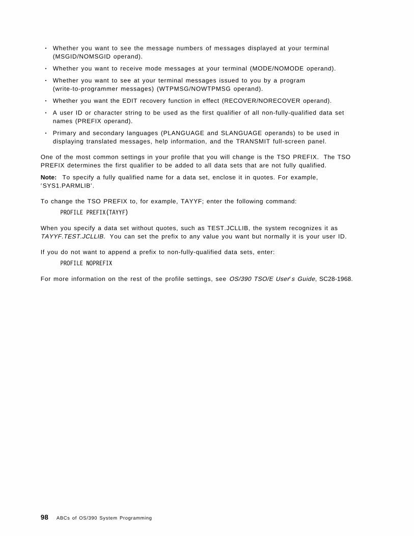
• Whether you want to see the message numbers of messages displayed at your terminal(MSGID/NOMSGID operand).
• Whether you want to receive mode messages at your terminal (MODE/NOMODE operand).
• Whether you want to see at your terminal messages issued to you by a program(write-to-programmer messages) (WTPMSG/NOWTPMSG operand).
• Whether you want the EDIT recovery function in effect (RECOVER/NORECOVER operand).
• A user ID or character string to be used as the first qualifier of all non-fully-qualified data setnames (PREFIX operand).
• Primary and secondary languages (PLANGUAGE and SLANGUAGE operands) to be used indisplaying translated messages, help information, and the TRANSMIT full-screen panel.
One of the most common settings in your profile that you will change is the TSO PREFIX. The TSOPREFIX determines the first qualifier to be added to all data sets that are not fully qualified.
Note: To specify a fully qualified name for a data set, enclose it in quotes. For example,′SYS1.PARMLIB′.
To change the TSO PREFIX to, for example, TAYYF; enter the following command:
PROFILE PREFIX(TAYYF)
When you specify a data set without quotes, such as TEST.JCLLIB, the system recognizes it asTAYYF.TEST.JCLLIB. You can set the prefix to any value you want but normally it is your user ID.
If you do not want to append a prefix to non-fully-qualified data sets, enter:
PROFILE NOPREFIX
For more information on the rest of the profile settings, see OS/390 TSO/E User′s Guide, SC28-1968.
98 ABCs of OS/390 System Programming

Figure 76. Backup and restore of OS/390
1.17.9 How to back up and restore OS/390
There are times when you have made a change to some system parameters and at the next scheduledIPL, the system simply refuses to start up. You realize that you have made a mistake in the change,and try to go back to the way things were before the change. That′s why you need to back up thesystem.
There are several other situations in which you need to perform recovery actions that besides ofmessing up a system change:
• When a hardware error occurs; for example, an DASD crash that took out a critical DASD volume.
• An I/O error during IPL due to a change to a system library, for example SYS1.NUCLEUS, orperhaps the master catalog, or any one of the critical system data sets that you need for asuccessful IPL.
• A corrupted system data set.
Before you start backing up your system, you have to set up a backup/restore strategy if it is not inplace in your environment. There are a number of aspects you should consider in your policy:
• The frequency of the backup
Normally, a full system backup is done weekly. This is sufficient if you do not have frequentsystem changes. For any minor changes before the scheduled backup, you might want to considerback up by data sets instead of a full system backup.
• The resource needed for backup
Chapter 1. OS/390 Implementation and Maintenance 99

The tape or cartridge drive (for example, IBM or compatible 3420, 3480, or 3490) is considered oneof the most commonly used backup/restore devices. The disadvantage of using these devices arethey are relatively slow as compared to a direct access device, like the IBM 3390.
• How many backup sets should you keep
You probably want to keep two sets of backup, if your resource permits. One set is kept at yourinstallation, and the other is kept offsite.
You can use the DFSMSdss program ADRDSSU to back up your system. Using ADRASSU, you canplan to have the following typical backup:
• Full or complete
All data in the system is backed up regardless of type, content, or access pattern. Figure 77shows sample JCL for doing a full volume dump operation.
� �//DSSDUMP JOB (),′ MVSSP′ , NOTIFY=&SYSUID,CLASS=A,MSGLEVEL=(1,1),// MSGCLASS=X//STEP1 EXEC PGM=ADRDSSU//SYSPRINT DD SYSOUT=A//DASD DD UNIT=3390,VOL=SER=MPDLB1,DISP=OLD//TAPE DD UNIT=(3480,2),VOL=SER=(TAPE01,TAPE02),// LABEL=(1,SL),DISP=(NEW,CATLG),DSNAME=MPDLB1.BACKUP//SYSIN DD * DUMP INDDNAME(DASD1) -
OUTDDNAME(BACKUP) -FULL OPTIMIZE(4) -COMPRESS
/*� �Figure 77. Sample JCL for a ful l volume dump
• Incremental
An incremental backup only backs up data that has been changed since a previous backup.Managing data this way requires the operating system to maintain some form of change control forindividual data sets. Figure 78 shows sample JCL for doing a dump on only data sets changedsince last backup.
� �//DSSDUMP JOB (),′ MVSSP′ , NOTIFY=&SYSUID,CLASS=A,MSGLEVEL=(1,1),// MSGCLASS=X//STEP1 EXEC PGM=ADRDSSU//SYSPRINT DD SYSOUT=A//TAPE DD UNIT=(3480,2),VOL=SER=(TAPE01,TAPE02),// LABEL=(1,SL),DISP=(NEW,CATLG),DSNAME=MPDLB1.BACKUP//SYSIN DD *
DUMP OUTDD(TAPE) -DS(INCL(**) -
BY((DSCHA EQ 1)))/*� �
Figure 78. Sample JCL for an incremental dump
• Selective
Data backed up under control of the user. Specific volumes and data sets are selected for backupbased on importance or access pattern. Figure 79 on page 101 shows sample JCL for backing updata sets that have a high level qualifier of ISP.
100 ABCs of OS/390 System Programming

� �//DSSDUMP JOB (),′ MVSSP′ , NOTIFY=&SYSUID,CLASS=A,MSGLEVEL=(1,1),// MSGCLASS=X//STEP1 EXEC PGM=ADRDSSU//SYSPRINT DD SYSOUT=A//TAPE DD UNIT=(3480,2),VOL=SER=(TAPE01,TAPE02),// LABEL=(1,SL),DISP=(NEW,CATLG),DSNAME=MPRES2.BACKUP//SYSIN DD *
DUMP OUTDD(TAPE) -DS(INCL(ISP.**)) -TOL(ENQF) OPTIMIZE(4) COMPRESS
/*� �Figure 79. Sample JCL for backing up selective data sets
For more information on the usage of ADRDSSU, see DFSMS/MVS DFSMSdss Storage AdministrationReference, SC26-4929.
Chapter 1. OS/390 Implementation and Maintenance 101

102 ABCs of OS/390 System Programming

Chapter 2. Defining subsystems
Subsystem initialization is the process of readying a subsystem for use in the system. IEFSSNxxmembers of SYS1.PARMLIB contain the definitions for the primary subsystems, such as JES2 or JES3,and the secondary subsystems, such as VPSS and DB2. For detailed information about the datacontained in IEFSSNxx members for secondary systems, refer to the installation manual for the specificsystem.
During system initialization, the defined subsystems are initialized. You should define the primarysubsystem (JES) first, because other subsystems, such as DB2, require the services of the primarysubsystem in their initialization routines. Problems can occur if subsystems that use the subsystemaffinity service in their initialization routines are initialized before the primary subsystem. After theprimary JES is initialized, then the subsystems are initialized in the order in which the IEFSSNxxparmlib members are specified by the SSN parameter. For example, for SSN=(aa,bb) parmlibmember IEFSSNaa would be processed before IEFSSNbb.
Subsystem definitions must be done in order to allow special programs to perform special tasks suchas:
• JES2
• JES3
• CICS
• DB2
• IMS
Copyright IBM Corp. 2000 103

Figure 80. IEFSSNxx member
2.1 IEFSSNxx (subsystem definitions) - keyword parameter form
A subsystem is a service provider that performs one or many functions, but does nothing until it isrequested. Subsystems are defined to MVS by the processing of the IEFSSNxx parmlib member duringIPL. You can use either the keyword format or positional format of the IEFSSNxx parmlib member. Werecommend that you use the keyword format, which allows you to define and dynamically manage yoursubsystems. You do this by:
• Issuing the IEFSSI macro
• Issuing the SETSSI system command
IEFSSNxx contains parameters that define the primary subsystem and the various secondarysubsystems that are to be initialized during system initialization.
IEFSSNxx allows you to:
• Name the subsystem initialization routine to be given control during master scheduler initialization.
• Specify the input parameter string to be passed to the subsystem initialization routine.
• Specify a primary subsystem name and whether you want it started automatically.
For information about writing subsystems, see OS/390 MVS Using the Subsystem Interface, SC28-1502.
The order in which the subsystems are initialized depends on the order in which they are defined inthe IEFSSNxx parmlib member on the SSN parameter. Unless you are starting the Storage
104 ABCs of OS/390 System Programming

Management Subsystem (SMS), start the primary subsystem (JES) first. Some subsystems require theservices of the primary subsystem in their initialization routines. Problems can occur if subsystemsthat use the subsystem affinity service in their initialization routines are initialized before the primarysubsystem. If you are starting SMS, specify its record before you specify the primary subsystemrecord.
Note: In general, it is a good idea to make the subsystem name the same as the name of the memberof the SYS1.PROCLIB used to start the subsystem. If the name does not match, you may receive errormessages when you start the subsystem.
2.1.1.1 Restrictions for IEFSSNxxThe following restrictions apply for IEFSSNxx:
• All subsystem definitions in a single IEFSSNxx member must use the same format. A singlemember cannot contain both positional and keyword definitions.
− If a member begins with the positional format and switches to the keyword format, processingof the member stops, and the IEFJ002I message is issued. The last subsystem definitionprocessed for the member is the last positional format definition before the switch. The systemdoes not process another definition of either format from the member, but continues processingwith the next member, if any.
− If a member begins with the keyword format and a positional format definition is found, thesystem issues a syntax error message, and processing continues with the next definition of thekeyword format.
Only subsystems that have been defined using the keyword format IEFSSNxx parmlib member, theIEFSSI REQUEST=ADD macro, or the SETSSI ADD system command can use the following dynamic SSIservices:
• Macros
IEFSSI REQUEST=ACTIVATE
IEFSSI REQUEST=DEACTIVATE
IEFSSI REQUEST=OPTIONS
IEFSSI REQUEST=SWAP
IEFSSI REQUEST=GET
IEFSSI REQUEST=PUT
IEFSSVT
• System commands
SETSSI ACTIVATE
SETSSI DEACTIVATE
You cannot use dynamic SSI services for subsystems defined with the positional form of this member.
Chapter 2. Subsystems 105

Figure 81. Statements and parameters for IEFSSNxx
2.1.2 Statements and parameters for IEFSSNxx
The storage management subsystem (SMS) is the only subsystem that can be defined before theprimary subsystem. Refer to the description of parmlib member IEFSSNxx in OS/390 MVS Initializationand Tuning Reference, SC28-1752, for SMS considerations. The statements and parameters forIEFSSNxx are:
SUBSYS The statement that defines a subsystem that is to be added to the system. Ifmore than one SUBSYS statement appears for the same subsystem name,the first statement will be the one used to define the subsystem. Theduplicate statements will be rejected with a failure message that is sent tothe console.
SUBNAME(subname) The subsystem name. The name can be up to four characters long; it mustbegin with an alphabetic or special character (#, @, or $), and the remainingcharacters (if any) can be alphanumeric or special.
CONSNAME(consname) The name of the console to which any messages that the SSI issues as partof initialization processing are to be routed. This name is optional and canbe two to eight characters long. This console name is also passed to theroutine named on the INITRTN keyword if it is specified. The default is toissue messages to the master console.
INITRTN(initrtn) The name of the subsystem initialization routine. This name is optional andcan be one to eight characters long. The first character can be eitheralphabetic or special. The remaining characters can be either alphanumeric
106 ABCs of OS/390 System Programming

or special. The routine receives control in supervisor state key 0. It must bethe name of a program accessible through LINKLIB.
INITPARM(initparm) Input parameters to be passed to the subsystem initialization routine. Theinput parameters are optional and are variable in length for a maximum of60 characters. If blanks, commas, single quotes, or parentheses are includedin the input parameters, the entire parm field must be enclosed in singlequotes. If the parm field is enclosed in single quotes, a single quote withinthe field must be specified as two single quotes. The INITPARM keywordcan only be specified if the INITRTN keyword is specified.
PRIMARY({NO|YES}) This parameter indicates whether this is the primary subsystem. Theprimary subsystem is typically a job entry subsystem (either JES2 or JES3).
This parameter is optional. Initialize the primary subsystem before anysecondary subsystem(s) except SMS. If you specify PRIMARY on more thanone statement, the system issues message IEFJ008I and defines the secondsubsystem but ignores the PRIMARY specification.
The IEFSSNxx parmlib member is the only place you can define the primarysubsystem. It cannot be defined using the dynamic SSI services IEFSSIREQUEST=ADD macro or the SETSSI ADD command. The default is NO.
START({YES|NO}) This parameter indicates whether an automatic START command should beissued for the primary subsystem.
If the parmlib entry for the primary subsystem is START(NO), the operatormust start it later with a START command. If the parmlib entry for the primarysubsystem does not specify the START parameter, it defaults to START(YES).
The START parameter cannot be specified for a secondary subsystem. If youspecify the PRIMARY(NO) parameter, there is no default for the STARTparameter.
2.1.2.1 Example
Define subsystem JES2 as a primary subsystem and the START command to be issued by the system.No initialization routine is required because subsystem JES2 builds the SSVT when the START commandis issued.
SUBSYS SUBNAME(JES2) PRIMARY(YES)
2.1.2.2 Parameter in IEASYSxx (or specified by the operator):
The SSN parameter in IEASYSxx identifies the IEFSSNxx member that the system is to use to initializethe subsystems, as follows:
SSN= {aa }{(aa,bb,...) }
The two-character identifier, represented by aa (or bb, and so forth) is appended to IEFSSN to identifyIEFSSNxx members of parmlib. If the SSN parameter is not specified, the system uses the IEFSSN00parmlib member.
The order in which the subsystems are defined on the SSN parameter is the order in which they areinitialized. For example, a specification of SSN=(13,Z5) would cause those subsystems defined in theIEFSSN13 parmlib member to be initialized first, followed by those subsystems defined in the IEFSSNZ5parmlib member. If you specify duplicate subsystem names in IEFSSNxx parmlib members, the systemissues message IEFJ003I to the SYSLOG, the master console, and consoles that monitor routing code10 messages.
Chapter 2. Subsystems 107
Some exits that use system services may run before other system address spaces are active. Youmust ensure that any address spaces required by the system services are available prior to invokingthe service.
For more information, see the section on handling errors in defining your subsystem in OS/390 MVSUsing the Subsystem Interface, SC28-1502.
2.1.2.3 Syntax rules for IEFSSNxxThe following rules apply to the creation of IEFSSNxx:
• Each SUBSYS statement in IEFSSNxx defines one subsystem to be initialized.
• Use columns 1 through 71. Do not use columns 72 through 80, because the system ignores thesecolumns.
• Comments may appear in columns 1 through 71 and must begin with /* and end with */ .
• A statement must begin with a valid statement type followed by at least one blank or end-of-line.
• A statement ends with the beginning of the next valid statement type or end-of-file.
• A statement can be continued even though there is no explicit continuation character.
• Operands must be separated by valid delimiters. Valid delimiters are a blank, or column 71. If theoperand contains parentheses, then the right parenthesis is accepted as a valid delimiter.
• Multiple occurrences of a delimiter (except for parentheses) are accepted, but treated as one.
2.1.2.4 IBM-supplied default for IEFSSNxxIf you do not specify the SSN system parameter, the system uses the IEFSSN00 parmlib member.IEFSSN00 specifies JES2 as the primary subsystem.
If you specify a set of IEFSSNxx members that do not identify a primary subsystem, the system issuesa message that prompts the operator to specify the primary subsystem.
108 ABCs of OS/390 System Programming

Figure 82. Subsystem interface - SSI
2.2 Subsystem interface - SSI
The SSI is an interface that provides communication between MVS and JES through the IEFSSREQmacro. The SSI is the interface used by routines (IBM, vendor, or installation-written) to requestservices of, or to pass information to, subsystems. An installation can design its own subsystem anduse the SSI to monitor subsystem requests. An installation can also use the SSI to request servicesfrom IBM-supplied subsystems. The SSI acts only as a mechanism for transferring control and databetween a requestor and the subsystem; it does not perform any subsystem functions itself.
MVS functions issue the IEFSSREQ macro to invoke JES. The calling routine uses the subsystemoption block (SSOB) and subsystem identification block (SSIB) to identify the required processing toJES3. The calling routine uses the IEFSSREQ macro to pass the SSIB and SSOB to JES.
Chapter 2. Subsystems 109

Figure 83. SSI control blocks and routines
2.2.1 SSI control blocks and routines
The MVS nucleus contains a control block named the JES control table (JESCT). This block contains apointer to the primary subsystem (JES3) communication vector table (SSCVT), which is located in CSA.There will always be at least two SSCVTs, one of which represents the MVS master subsystem.
The macro that provides communication between MVS and JES3 is the IEFSSREQ macro. MVSfunctions issue this macro to invoke JES3. The calling routine uses the subsystem option block (SSOB)and subsystem identification block (SSIB) to identify the required processing to JES3. The callingroutine uses the IEFSSREQ macro to pass the SSIB and SSOB to JES3. The control blocks involvedare:
JESCT JES control table (JESCT). A control block in the MVS nucleus that contains informationused by subsystem interface routines.
SSCVT Primary subsystem communication vector table (SSCVT). This control block is the commonstorage area that contains information used by the subsystem interface routines.
SSVT The subsystem vector table (SSVT). The SSVT resides in the JES3 common service area(CSA) and contains the following information:
SSOB Subsystem options block (SSOB). The control block into which MVS places afunction code when communicating with JES3 over the subsystem interface. Thefunction code identifies a requested service.
110 ABCs of OS/390 System Programming

SSIB Subsystem identification block (SSIB). The control block into which MVS placesthe name of the subsystem to which it is directing a request over the subsysteminterface.
Chapter 2. Subsystems 111

Figure 84. SSI request to master subsystem
2.2.2 SSI request to master subsystem
The IEFJSREQ routine checks the validity of the SSOB and SSIB; the request routine determines thatthe target subsystem exists and is started. It next uses the function code to determine if thesubsystem performs the requested function and to derive the address of a routine to which the requestis be passed. The SSOB contains the function code requested by the caller and the SSIB contains thename of the subsystem to perform the function requested.
There are 15 SSI functions supported by the master subsystem but several of the routines performmore than one function.
The SSVT contains a matrix of the function codes and in the visual the first function code supported bythe MSTR subsystem is function code 4. The number 4 shown in the fourth position indicates that theroutine that gets control is the fourth routine pointer (ptr) shown after the function code matrix in theSSVT.
Function code 15, is used by the master subsystem (MSTR) to verify the subsystem (JES) name whenJES initializes and is the third routine pointer as function code 15 has a 3 in the matrix.
112 ABCs of OS/390 System Programming
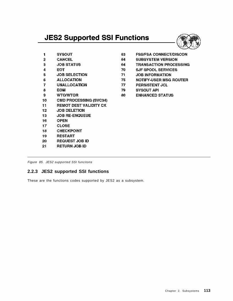
Figure 85. JES2 supported SSI funcitons
2.2.3 JES2 supported SSI functions
These are the functions codes supported by JES2 as a subsystem.
Chapter 2. Subsystems 113

Figure 86. JES3 supported SSI functions
2.2.4 JES3 supported SSI functions
These are the functions codes supported by JES3 as a subsystem.
114 ABCs of OS/390 System Programming

Chapter 3. Job Management
OS/390 Job Management in an OS/390 system uses a job entry subsystem (JES) to receive jobs intothe operating system, schedule them for processing by OS/390, and to control their output processing.JES provides supplementary job management, data management, and task management functionssuch as: scheduling, control of job flow, and spooling. JES is designed to provide efficient spooling,scheduling, and management facilities for the OS/390 system.
For a program to execute on the computer and perform the work it is designed to do, the programmust be processed by the operating system. The operating system consists of a base control program(BCP) with a job entry subsystem (JES2 or JES3) and DFSMSdfp installed with it.
For the operating system to process a program, programmers must perform certain job control tasks.These tasks are performed through the job control statements, (JCL). The job control tasks areperformed by the JES and are:
• Entering jobs• Processing jobs• Requesting resources
Copyright IBM Corp. 2000 115
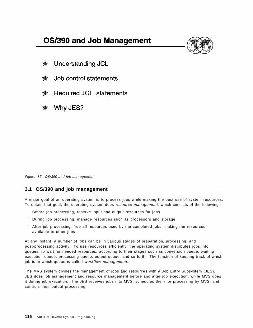
Figure 87. OS/390 and job management
3.1 OS/390 and job management
A major goal of an operating system is to process jobs while making the best use of system resources.To obtain that goal, the operating system does resource management, which consists of the following:
• Before job processing, reserve input and output resources for jobs
• During job processing, manage resources such as processors and storage
• After job processing, free all resources used by the completed jobs, making the resourcesavailable to other jobs
At any instant, a number of jobs can be in various stages of preparation, processing, andpost-processing activity. To use resources efficiently, the operating system distributes jobs intoqueues, to wait for needed resources, according to their stages such as conversion queue, waitingexecution queue, processing queue, output queue, and so forth. The function of keeping track of whichjob is in which queue is called workflow management.
The MVS system divides the management of jobs and resources with a Job Entry Subsystem (JES).JES does job management and resource management before and after job execution, while MVS doesit during job execution. The JES receives jobs into MVS, schedules them for processing by MVS, andcontrols their output processing.
116 ABCs of OS/390 System Programming

Figure 88. Job management
3.1.1 Understanding JCL
To get your MVS system to do work for you, you must describe to the system the work you want doneand the resources you will need. You use Job Control Language (JCL) to provide this information toMVS.
One way of thinking about JCL is to compare it to a menu in a restaurant.
If you are a customer at a restaurant, you and the other customers don′ t just walk into the kitchen andstart cooking your own dinners, that would defeat the very purpose of going to a restaurant. Instead,from a menu describing all the restaurant has to offer, you select items to make up an order,specifying which entrees you want, which salad dressing you prefer, and any other special requestsyou have. You then ask the waiter to take your order to the kitchen.
In the kitchen, a team of chefs divides up the work and the appropriate ingredients in order to prepareeach dish as quickly and efficiently as possible. While the meals are being prepared, you and yourfriends can ignore what ′s going on in the kitchen, engaging instead in dinner conversation, catching upon the latest news. When the waiter brings your meal out, you concentrate on your enjoyment of themeal.
How does this relate to JCL?
Now imagine yourself back at the office using your OS/390 system, and think of JCL as the menu. Inthe same way that you and the other diners select items from the menu and place orders for the waiter
Chapter 3. Job Management 117

to take to the team of chefs, you and other OS/390 users use JCL to define work requests (called jobs),and use a job entry subsystem (JES) to submit those jobs to OS/390.
Using the information that you and the other users provide with JCL statements, OS/390 allocates theresources needed to complete all of your jobs, just as the kitchen chefs divided up the work to preparethe orders of all the customers.
And just as the chefs worked in the kitchen while you and the other diners devoted your attention towhat was going on at your tables, OS/390 completes the submitted jobs in the background of thesystem, enabling you and the other users to continue working on other activities in the foreground.
And just as the waiter conveys the results of the chef′s work to you, JES presents the output of the jobsto you.
Figure 89 on page 119 shows an overview of the job-submission process. The user performs the partson the left side of the figure, and the system performs the parts on the right. In this figure, OS/390 andJES comprise the “system.”
118 ABCs of OS/390 System Programming

Figure 89. JCL-related actions (user and MVS)
3.1.2 Job control statements
For every job that you submit, you need to tell to MVS where to find the appropriate input, how toprocess that input (that is, what program or programs to run), and what to do with the resulting output.
You use JCL to convey this information to MVS through a set of statements known as job controlstatements. The set of job control statements is quite large, enabling you to provide a great deal ofinformation to MVS.
Most jobs, however, can be run using a very small subset of these control statements. Once youbecome familiar with the characteristics of the jobs you typically run, you may find that you need toknow the details of only some of the control statements.
Within each job, the control statements are grouped into job steps. A job step consists of all thecontrol statements needed to run one program. If a job needs to run more than one program, the jobwould contain a different job step for each of those programs. The job control statements consist of:
• JCL statements• JES2 control statements• JES3 control statements
A JCL statement:
• Consists of one or more records 80 bytes length.• Is coded from column 1 to column 71, in uppercase.• Starts with a / / at the beginning of the line.
Chapter 3. Job Management 119

• A commentary line begins with a / /* .• A line with only / / and blanks indicates end of job.• A comma indicates that the statement has continuation.• A continuation of a statement from a previous line must start from column 4 to 16.• Comments must be separated from operators/parameters by at least one blank.
3.1.2.1 Required control statements
Every job must contain a minimum of the following two types of control statements:
• A job statement, to mark the beginning of a job and assign a name to the job.
//jobname JOB ............
The job statement is also used to provide certain administrative information, including security,accounting, and identification information. The required job statement parameters depends on theJES customization. Every job has one (and only one) job statement.
• An EXEC (execute) statement, to mark the beginning of a job step, to assign a name to the step,and to identify the program or procedure to be executed in the step.
//stepname EXEC ............
You can add various parameters to the EXEC statement to customize the way the programexecutes. Every job has at least one EXEC statement.
In addition to the JOB and EXEC statements, jobs usually contain:
• One or more DD (data definition) statements, to identify and describe the input and output data tobe used in the step.
//ddname DD ............
The DD statement may be used to request a existing data set, to define a new data set, to define atemporary data set, or to define and specify the characteristics of the output.
You can create your own JCL by using the TSO/ISPF Edit option. When you have finished entering theJCL into the data set, submit the job by entering the SUBMIT command from the ISPF EDIT commandline, as shown in the following example.
EDIT ---- userid.SORT.JCL -------------------------- LINE 00000000 COL 001 080COMMAND ===> SUBMIT SCROLL ===> CSR********************************* TOP OF DATA *******************************//jobname JOB ′ accounting data′//stepname EXEC ′ parameter′//ddname DD ′ data parameter′// .// .
Figure 90. Submit the JCL to the System as a Job
120 ABCs of OS/390 System Programming

Figure 91. JES2 and JES3 main differences
3.2 JES2 and JES3 main differences
IBM provides two JESs from which to choose: JES2 and JES3. In an installation that has only oneMVS image, JES2 and JES3 perform similar functions. That is, they read jobs into the system, convertthem to internal machine-readable form, select them for processing, process their output, and purgethem from the system. However, for an installation that has more than one MVS image in aconfiguration, there are noticeable differences in how JES2 and JES2 work.
Each JES2 in each MVS image exercises independent control over its job processing functions. Thatis, within the configuration, each JES2 processor controls its own job input, job scheduling, and joboutput processing.
In contrast, JES3 exercises centralized control over its processing functions through a single globalJES3 processor. The global processor provides all job selection, scheduling, and device allocationfunctions for all the other JES3 systems. The centralized control that JES3 exercises providesincreased job scheduling control, deadline scheduling capabilities, and increased control by providingits own device allocation.
To better understand the functional differences between JES2 and JES3, refer to OS/390 JES2Initialization and Tuning Guide, SC28-1791, and OS/390 JES3 Initialization and Tuning Guide, SC28-1802.
Chapter 3. Job Management 121

Figure 92. JES2
3.3 JES2
JES2 is descended from Houston automatic spooling priority (HASP). HASP is defined as a computerprogram that provides supplementary job management, data management, and task managementfunctions such as scheduling, control of job flow, and spooling. HASP remains within JES2 as theprefix of most module names and the prefix of messages sent by JES2 to the operator.
JES2, or Job Entry Subsystem 2, is a functional extension of the HASP II program that receives jobsinto the system and processes all output data produced by the job. So what does all that mean?Simply stated, JES2 is the component of OS/390 that provides the necessary functions to get jobs into,and output out of, the OS/390 system. It is designed to provide efficient spooling, scheduling, andmanagement facilities for the OS/390 operating system.
You can run OS/390 in your installation in many processing configurations that range from a singleMVS image with a single JES2 that is completely isolated from other processing systems to one that isa part of a worldwide processing network. The choice of configuration complexity is yours andgenerally is a dynamic one that grows as your business needs grow.
The visual shows the topics discussed in this chapter about JES2.
122 ABCs of OS/390 System Programming

Figure 93. Relationship of JES2 to BCP
3.3.1 JES2 functions
To manage job input/output, JES2 controls a number of functional areas, all of which you cancustomize to your installation′s need. Some of the major functional areas and processing capabilitiesare:
• Getting work into and out of MVS (input/output control):
JES2 controls output devices such as local and remote printers, punches, and card readers. Youdefine each device to JES2 using JES2 initialization statements. All are directly under JES2 ′scontrol with the exception of those printers that operates under the Print Services Facility (PSF).Printed and punched output can be routed to a variety of devices in multiple locations. The controlJES2 exercises over its printers ranges from the job output classes and job names from which theprinter can select work to such specifications such as the forms on which the output is printed.This control allows the system programmer to establish the job output environment most efficientlywithout causing unnecessary printer backlog or operator intervention. Through JES2, theinstallation defines the job input classes, reader specifications, and output device specifications.As a result, JES2 is the central point of control over both the job entry and job exit phases of dataprocessing.
• Maximizing efficiency through job selection and scheduling:
JES2 allows the installation to define work selection criteria. It can be specific for each outputdevice (local and remote printers and punches and offload devices). The work selection criteriaare defined in the device initialization statements and can be changed dynamically using JES2commands. You can define:
Chapter 3. Job Management 123

− Specification of job and output characteristics that JES2 considers when selecting work for anoutput device
− Priority of the selection characteristics
− Characteristics of the printer and job that must match exactly
A job′s output is grouped based on the data sets output requirements. The requirements may bedefined in the job′s JCL or by JES2-supplied defaults.
When selecting work to be processed on a device, JES2 compares the device characteristics withthe output requirements. If they match, JES2 sends the output to the device. If they do not match,JES2 does not select the work for outpt until the operator changes the device characteristics or theoutput requirements.
• Offloading work and backing up system workload:
JES2 gives your installation the capability to offload data from the spool and later reload data tothe spool. This is useful if you need to:
− Preserve jobs and SYSOUT across a cold start
− Migrate your installation to another release of JES2
− Convert to another DASD type for spool
− Archive system jobs and SYSOUT
− Relieve a full-spool condition during high-use periods
− Provide a backup for spool data sets
− Back up network connections
JES2 offers many selection criteria to limit the spool offload operation. These selection criteria canbe changed by operator command, according to initial specification in the JES2 initializationstatements.
• System security:
JES2 provides a basic level of security for resources through initialization statements. That controlcan be broadened by implementing several JES2 exits available for this purpose. A more completesecurity policy can be implemented with System Security Facility (SAF) and a security product suchas RACF.
• Supporting advanced function printers (AFPs)
JES2 is responsible for all phases of job processing and monitors the processing phase. The basecontrol program (BCP) and JES2 share responsibility in the OS/390 system. JES2 is responsible for jobentry (input), the base control program for device allocation and actual job running, and finally JES2 forjob exit (output).
Figure 94 on page 125 presents a view of the job phases.
124 ABCs of OS/390 System Programming

Figure 94. JES2 job fLow
3.3.2 JES2 - Phases of job processing
The job queues contain jobs:
• Waiting to run - conversion queue• Currently running - execution queue• Waiting for their output to be produced - output queue• Having their output produced - hard-copy (print/punch) queue• Waiting to be purged from the system - purge queue
The six phases of job processing are as follows:
1. Input phase
JES2 accepts jobs, in the form of an input stream, from input devices, internal readers, other nodesin a job entry network, and from other programs.
The internal reader is a program that other programs can use to submit jobs, control statements,and commands to JES2. Any job running in MVS can use an internal reader to pass an inputstream to JES2. JES2 can receive multiple jobs simultaneously through multiple internal readers.MVS uses internal readers, allocated during system initialization, to pass to JES2 the job controllanguage (JCL) for started tasks, START and MOUNT commands, and TSO LOGON requests.
The system programmer defines internal readers to be used to process all batch jobs other thanSTCs and TSO requests. These internal readers are defined in JES2 initialization statements andJES2 allocates them during JES2 initialization processing. The internal readers for batch jobs canbe used for STCs and TSO requests, if not processing jobs.
Chapter 3. Job Management 125

JES2 reads the input stream and assigns a job identifier to each JOB JCL statement. JES2 placesthe job′s JCL, optional JES2 control statements, and SYSIN data onto DASD data sets called spooldata sets. JES2 then selects jobs from the spool data sets for processing and subsequent running.
2. Conversion phase
JES2 uses a converter program to analyze each job′s JCL statements. The converter takes thejob ′s JCL and merges it with JCL from a procedure library. The procedure library can be defined inthe JCLLIB JCL statement, or system/user procedure libraries can be defined in the PROCxx DDstatement of the JES2 startup procedure. Then, JES2 converts the composite JCL intoconverter/interpreter text that both JES2 and the job scheduler functions of MVS can recognize.Next, JES2 stores the converter/interpreter text on the spool data set. If JES2 detects any JCLerrors, it issues messages, and the job is queued for output processing rather than run. If thereare no errors, JES2 queues the job for execution.
3. Processing phase
In the processing phase, JES2 responds to requests for jobs from the MVS initiators. An initiator isa system program that is controlled by JES or by WLM (in goal mode, with WLM Batch InitiatorManagement).
JES2 initiators are defined to JES2 through JES2 initialization statements. JES2 initiators arestarted by the operator or by JES2 automatically when the system initializes. The installationassociates each initiator with one or more job classes in order to obtain an efficient use ofavailable system resources. Initiators select jobs whose classes match the initiator assignedclass, obeying the priority of the queued jobs.
WLM initiators are started by the system automatically based on the performance goals, relativeimportance of the batch workload, and the capacity of the system to do more work. The initiatorsselect jobs based on their service class and the order they were made available for execution.Jobs are routed to WLM initiators via a JOBCLASS JES2 initialization statement.
In goal mode, with WLM Batch Management, a system can have WLM initiators and/or JES2initiators.
After a job is selected, the initiator invokes the interpreter to build control blocks from theconverter/interpreter text that the converter created for the job. The initiator then allocates theresources specified in the JCL for the first step of the job. This allocation ensures that the devicesare available before the job step starts running. The initiator then starts the program requested inthe JCL EXEC statement.
JES2 and the MVS Basic Control Program (BCP) communicate constantly to control systemprocessing. The communication mechanism, known as the subsystem interface, allows MVS torequest services of JES2. For example, a requestor can ask JES2 to find a job, message orcommand processing, or open (access) a SYSIN or SYSOUT data set. Further, the base controlprogram notifies JES2 of events such as messages, operator commands, the end of a job, or theend of a task.
By recognizing the current processing phase of all jobs on the job queue, JES2 can manage theflow of jobs through the system.
4. Output phase
JES2 controls all SYSOUT processing. SYSOUT is a data set in a printer device format, that is, it isready to be printed. Intermediately, a sysout file is stored in the spool data set. There are manyadvantages in spooling a sysout to JES, such as faster processing (DASD is faster than a printer),optimization of the printer devices, and spool backup and archive. MVS directs to sysout systemmessages related to job execution.
After a job finishes, JES2 analyzes the characteristics of the job′s output in terms of its output classand device setup requirements; then JES2 groups data sets with similar characteristics. JES2queues the output for print processing.
126 ABCs of OS/390 System Programming

5. Hardcopy phase
JES2 selects output for processing from the output queues by output class, route code, priority, andother criteria. The output queue can have outputs to be processed locally or output to beprocessed at a remote location (either an RJE workstation or another node). After processing allthe output for a particular job, JES2 puts the job on the purge queue.
6. Purge phase
When all processing for a job completes, JES2 releases the spool space assigned to the job,making the space available for allocation to subsequent jobs. JES2 then issues a message to theoperator indicating that the job has been purged from the system.
Chapter 3. Job Management 127

Figure 95. Spool data set
3.3.3 JES2 spool
The Simultaneous Peripheral Operations Online (spool) data set is the direct access device or devicesthat contains the spool data.
Spooling is a process by which the system manipulates its work.
This includes:
• Using storage on direct access storage devices (DASD) as buffer storage to reduce processingdelays when transferring data between peripheral equipment and a program to be run.
• Reading and writing input and output streams on an intermediate device for later processing oroutput.
• Performing an operation such as printing while the computer is busy with other work.
For these reasons, spooling is critical to maintain performance in the MVS-JES2 environment.
128 ABCs of OS/390 System Programming

Figure 96. JES2 checkpoint data set
3.3.4 JES2 checkpointing
Errors can occur while processing jobs and data. Some of these errors can result in the halting of allsystem activity. Other errors can result in the loss of jobs or the invalidation of jobs and data. If sucherrors occur, it is preferable to stop JES2 in such a way that allows processing to be restarted withminimal loss of jobs and data. The checkpoint data set, checkpointing, and the checkpointreconfiguration dialog all help to make this possible.
Checkpoint is the data set that JES2 maintains on either DASD or a Coupling Facility that permits JES2to perform two separate functions:
1. Job and output queue backup to ensure ease of JES2 restart, since it contains information aboutwhat work is yet to be processed and how far along that work has progressed.
2. In a multi-access spool (MAS) environment, member-to-member workload communication toensure efficient independent JES2 operation.
JES2 periodically updates the checkpoint data set by copying the changed information from thein-storage copy to the checkpoint data set copy. Information in the checkpoint data set is critical toJES2 for normal processing as well as in the event that a JES2 or system failure occurs.
Checkpointing is the periodic copying of a member ′s in-storage job and output queues to thecheckpoint data set. In a MAS environment, checkpointing ensures that information about a member′sin-storage job and output queues is not lost if the member loses access to these queues as the resultof either hardware or software errors. Because all members in a JES2 MAS configuration operate in aloosely-coupled manner, each capable of selecting work from the same job and output queues,
Chapter 3. Job Management 129

checkpointing allows all members to be aware of current queue status. Within the single-memberenvironment, the checkpoint function operates solely as a backup to the “in-storage” job and output(SYSOUT) queues maintained by JES2.
There are three ways of specifying the checkpoint configuration mode. The type of mode you selectdepends upon your JES2 configuration:
1. DUPLEX-mode processing with backup:
JES2 can operate its checkpoint configuration in DUPLEX mode if you have defined two checkpointdata sets, a primary and a duplex. They can be either in DASD or a Coupling Facility. The duplexdata set is updated once for every write to the primary. If the primary data set suffers an error, theduplex can provide either an exact duplicate of the primary or a very similar, almost current(depending on when it was last updated) copy of the checkpoint data.
IBM recommends that all members in the JES2 configuration operate, if possible, withDUPLEX=ON in the CKPTDEF. This provides the greatest protection from checkpoint error.
2. DUPLEX-mode processing without backup:
Processing with a single checkpoint data set is not recommended in most cases. If that data setbecomes damaged, lost, or suffers an I/O error, and your member experiences a concurrentfailure, you will not have a checkpoint data set available to restart JES2. But you have the benefitthat JES2 will not need to read/write to two data sets. However, depending on your specificvolume or structure use and configuration, it might not be practical for particular members of yourJES2 configuration to maintain a backup checkpoint (for example, in systems that manage basicallyonline transactions).
3. DUAL-mode processing:
This configuration also uses two data sets, but in a “flip-flop” scheme; that is, individual membersdo not always read and write to the same CKPTn data set. However, the member performing aread always uses the checkpoint data set last updated. This is not required in a single-memberenvironment. However, it is recommended in a MAS environment, if the installation is sufferingfrom degraded system performance due to high checkpoint data set I/O. The use of the changeprovides reduced I/O to the checkpoint data set during most, if not all, update accesses by amember of the multi-access spool configuration.
Note: This mode cannot be used if any checkpoint data set resides on a Coupling Facilitystructure.
JES2 provides a dynamic means by which the current checkpoint configuration can be changed. It isthe checkpoint reconfiguration dialog and can be initiated by the operator system or by JES2. JES2 willenter a checkpoint reconfiguration for any of these reasons:
• To complete initialization processing:
− Either JES2 could not determine the checkpoint data set specifications, or JES2 requiresoperator verification of the data set specifications
− JES2 startup option
− Checkpoint statement definition
• To correct an I/O error to the checkpoint data set
• To move the checkpoint off a volatile Coupling Facility structure
130 ABCs of OS/390 System Programming
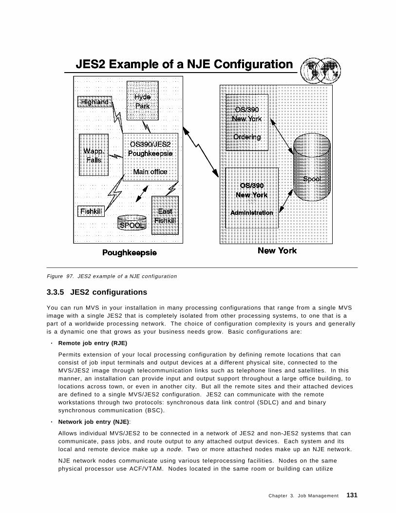
Figure 97. JES2 example of a NJE configuration
3.3.5 JES2 configurations
You can run MVS in your installation in many processing configurations that range from a single MVSimage with a single JES2 that is completely isolated from other processing systems, to one that is apart of a worldwide processing network. The choice of configuration complexity is yours and generallyis a dynamic one that grows as your business needs grow. Basic configurations are:
• Remote job entry (RJE)
Permits extension of your local processing configuration by defining remote locations that canconsist of job input terminals and output devices at a different physical site, connected to theMVS/JES2 image through telecommunication links such as telephone lines and satellites. In thismanner, an installation can provide input and output support throughout a large office building, tolocations across town, or even in another city. But all the remote sites and their attached devicesare defined to a single MVS/JES2 configuration. JES2 can communicate with the remoteworkstations through two protocols: synchronous data link control (SDLC) and and binarysynchronous communication (BSC).
• Network job entry (NJE) :
Allows individual MVS/JES2 to be connected in a network of JES2 and non-JES2 systems that cancommunicate, pass jobs, and route output to any attached output devices. Each system and itslocal and remote device make up a node. Two or more attached nodes make up an NJE network.
NJE network nodes communicate using various teleprocessing facilities. Nodes on the samephysical processor use ACF/VTAM. Nodes located in the same room or building can utilize
Chapter 3. Job Management 131

channel-to-channel adapters (CTCA) or telecommunications links. Nodes that are geographicallydispersed utilize SNA or BSC telecommunication links.
• Single system configuration
The spool and checkpoint data set are not shared between MVS systems. This configuration issuitable for an installation that has a relatively small workload, or possibly an installation thatrequires an image to be isolated from the remainder of the data processing complex, possibly tomaintain a high degree of security.
• Multi-access spool (MAS)
Also referred to as a multi-system configuration, MAS consists of two or more JES2/MVS imagessharing the same spool and checkpoint data sets. There is no direct connection between the JES2processors. The shared direct access data sets provide the communication link. Each JES2 in amultiple system complex operates independently of the other JES2 processors in the configuration.
The JES2 share a common job queue and a common output queue, which reside on the checkpointdata sets. These common queues enable each JES2 to share in processing the installation ′sworkload. Jobs can run on whatever MVS image is available and print or punch output onwhatever MVS image has an available device with the proper requirements. Users can alsorequest jobs to run on a particular processor and output to print or punch on a specific device. Ifone MVS image in the configuration fails, the others can continue processing by selecting workfrom the shared queues and optionally take over for the failed MVS image. Only work in processon the failed MVS image is interrupted; the other JES2 systems continue processing.
• Poly-JES
MVS allows more than one JES2 subsystem to operate concurrently. One subsystem must bedesigned as the primary subsystem and the others are defined as secondary subsystems. Thesecondary JES2 does not have the same capabilities, and some restrictions apply to its use. Forexample, TSO/E users can only access the primary subsystem. However, secondary JES2 can beuseful in testing user modifications while the the primary JES2 is being used for production.
Figure 97 on page 131 shows an example of a JES2 configuration. Poughkeepsie is the MVS site, withremote stations at Fishkill, East Fishkill, and so forth. They comprise the Poughkeepsie node. Theyare connected with the New York node (MAS configuration).
132 ABCs of OS/390 System Programming

Figure 98. JES2 customization
3.3.6 JES2 customization
JES2 is designed to be tailored to meet an installation′s particular processing needs. You can addressyour basic customization needs when you create the JES2 initialization data set. If you find this controlover JES2 processing to be insufficient, JES2 also provides exits and table pairs to change many JES2functions or processes.
3.3.6.1 JES2 initialization data set
The JES2 initialization data set provides all the specifications that are required to define:
• Output devices (printers and punches)
• Job classes
• The JES2 spool environment
• The checkpoint data sets
• The trace facility
• And every other JES2 facility and function
A sample JES2 initialization data set is shown in Appendix B, “Job Management” on page 295.
With a set of approximately 70 initialization statements, you can control all JES2 functions. Eachinitialization statement groups initialization parameters that define a function. The use of most JES2
Chapter 3. Job Management 133

initialization statements is optional. Many of the parameters provide defaults. You need define onlythe required parameters and those to fit your installation ′s needs.
In the IBM-provided sample data set SYS1.VnRnMn.SHASSAMP data set, the HASI* members aresamples you can tailor to meet your installation′s needs.
JES2 initialization statements give the system programmer a single point of control to define aninstallation′s policies regarding the degree of control users have over their jobs. For example,consider the confusion an installation would experience if users were allowed to define their own jobclasses and priorities. Very likely, all users would define all their jobs as top priority, resulting in noeffective priority classifications at all.
JES2 provides a sort of commands you can use to can dynamically alter JES2 customization wheneveryour processing needs change. Here are some of 71 available JES2 initialization statements:
BUFDEF - Local JES2 Buffer DefinitionCKPTDEF - JES2 Checkpoint DefinitionCONDEF - JES2 Console Communication DefinitionDEBUG - JES2 Debug OptionDESTDEF - Defining How Destinations Are ProcessedEXIT(nnn) - Exit and Exit Routine AssociationINITDEF - Initiator DefinitionINTRDR - Internal ReaderJOBCLASS - Job, Started Task, and Time Sharing User ClassJOBDEF - Job DefinitionJOBPRTY(n) - Job PriorityLOGON(nnn) - Identification of JES2 to VTAMMASDEF - Multi-Access Spool DefinitionMEMBER(nn) - Define Members of a Multi-Access SpoolNETACCT - Define Network/JES2 Account Number CorrespoNODE (xxxxxxxx) - Define a Network Node to JES2OPTSDEF - Start Options Processing DefinitionsOUTCLASS(v) - SYSOUT Class CharacteristicsOUTDEF - Job Output DefinitionOUTPRTY(n) - Job Output PriorityPRINTDEF - Local Print Environment DefinitionRMT(nnnnn) - SNA RJE WorkstationSMFDEF - JES2 SMF Buffer DefinitionSPOOLDEF - Spool Volume DefinitionTRACEDEF - Trace Facility Definition
For more information, refer to OS/390 JES2 Initialization and Tuning Reference, SC28-1792.
When you are first getting started, you need not define or even be concerned about some of the moresophisticated processing environments such as a multi-access spool complex, nodes, or remoteworkstations. You are simply building a base on which your installation can grow. There is no need tobe overwhelmed with the potential complexity of your JES2 system.
As your installation grows, you will likely use more and more of JES2′s available functions. Thesample data set shipped in SYS1.PARMLIB contains all default values and requires only the addition ofinstallation-defined devices and installation-specific values. It contains all the JES2 initializationstatements and the defaults for all parameters for which they are provided.
134 ABCs of OS/390 System Programming

3.3.6.2 JES2 table pairs
Table pairs provide a facility to change, delete, or add to JES2 processing and/or function. It is astructured mechanism to change JES 2 processing that imposes fewer constraints and less complexitythan using exit points.
A number of JES2 functions (such as initialization statement processing, command processing, andmessage building) use tables. You can customize these JES2 functions, and others, by extending theirassociated tables. JES2 examines two tables, known as table pairs. The first table is the JES2 table. Itprovides the default processing specifications. The second table is the user table. The user table isused to extend, change, or delete the default processing specifications. For example, you can addyour own JES2 commands and messages, add a new initialization statement or parameter, abbreviatethe length of a JES2 command, or delete an unnecessary command to prevent its accidental misuse.For more details about table pairs, refer to OS/390 JES2 Macros, SC28-1795.
Chapter 3. Job Management 135

Figure 99. Areas of JES2 modification
3.4 JES2 exits
JES2 may not satisfy all installation-specific needs at a given installation. When you modify JES2 codeto accomplish your specific functions, you are susceptible to the migration and maintenanceimplications that result from installing new versions of JES2. JES2 exits allow you to modify JES2processing without directly affecting JES2 code. In this way, you keep your modifications independentof JES2 code, making migration to new JES2 versions easier and making maintenance lesstroublesome.
JES2 provides various strategic locations, called exit points, from where an installation-written exitroutine can be invoked. JES2 can have up to 256 exits, each identified by a number from 0 to 255.JES2 code includes a number of IBM-defined exits, which have already been strategically placed inJES2 code. For these IBM-defined exits you need only write your own exit routines and incorporatethem via the EXIT(nnn) and LOAD(xxxxxx) initialization statements, where nnn is the exit point numberand xxxxxx is the load module name.
If the IBM-defined exits are not sufficient, you can define your own exit points. However, exitsestablished by you are modifications to JES2 code, and you must remember that you run a greater riskof disruption when installing a new version of JES2 code. The new JES2 code into which you haveplaced your exits may have significantly changed since your insertion of your exit point.
The IBM-defined exits can be classified into two categories:
• Not job-related exits:
136 ABCs of OS/390 System Programming

These are exits taken during functions not necessarily related to individual jobs (for example, JES2initialization, JES2 termination, RJE, and JES2 command processing).
• Job-related exits:
These exits are described in further detail in the following section.
Chapter 3. Job Management 137
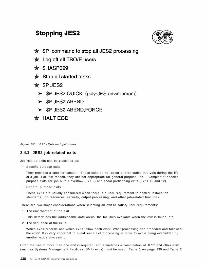
Figure 100. JES2 - Exits on input phase
3.4.1 JES2 job-related exits
Job-related exits can be classified as:
• Specific purpose exits
They provides a specific function. These exits do not occur at predictable intervals during the lifeof a job. For that reason, they are not appropriate for general-purpose use. Examples of specificpurpose exits are job output overflow (Exit 9) and spool partitioning exits (Exits 11 and 12).
• General purpose exits
These exits are usually considered when there is a user requirement to control installationstandards, job resources, security, output processing, and other job-related functions.
There are two major considerations when selecting an exit to satisfy user requirements:
1. The environment of the exit
This determines the addressable data areas, the facilities available when the exit is taken, etc.
2. The sequence of the exits
Which exits precede and which exits follow each exit? What processing has preceded and followedthe exit? It is very important to avoid some exit processing in order to avoid being overridden byanother exit′s processing.
Often the use of more than one exit is required, and sometimes a combination of JES2 and other exits(such as Systems Management Facilities (SMF) exits) must be used. Table 1 on page 139 and Table 2
138 ABCs of OS/390 System Programming

on page 141 list the job-related exits in order to help you decide which exits to choose to controlcertain processes or functions during the life of a job.
Figure 100 on page 138 shows the available exit points and their sequence in the job input phase.Many installations use input service exits to control installation standards, tailor accountinginformation, and provide additional controls. When choosing a exit to act in this phase, it is importantto consider all sources of jobs, especially if you want to select jobs from some sources to followstandards. For more details, refer to JES2 Installations Exits, SC28-1793.
Table 1 (Page 1 of 3). JES2 job-related exits
Exit Exit title Comments and some specific uses
1 Print/punch jobseparator
Taken when a job′s data sets have been selected for printing or punching,prior to the check for the standard separator page.
Uses:
• Selectively produce separators for particular users or particular jobclasses.
• Place the company′s logo on header page.• Suppress production of standard separator.
2 JOB statement scan The first exit taken for a job and before the statement is processed.
Uses:
• Enforce security and standards.• Alter/supply JOB statement parameters.• Selectively cancel or purge jobs.
3 JOB statementaccounting fieldscan
Taken after JOB statement has been processed.
Uses:
• Process nonstandard accounting fields.• Pass information to subsequent exits through the JCT user fields.
4 JCL and JES2control statementscan
Taken for each JCL and JECL statement submitted but not including JOB andPROCLIB JCL statements.
Uses:
• Process your own installation-defined JES2 control statementsub-parameters.
• Alter/supply JCL parameters.
6 Converter/InterpreterText scan
A good exit for scanning JCL because of structured text and single record foreach statement (no continuation).
7 $JCT Read/Write(JES2 environment)
Receive control whenever control block I/O is performed by the JES2 maintask.
Uses:
• Read or write your own installation-defined job-related control blocks tospool along with the reading and writing of JES2 control.
8 $JCT Read/Write(user/subtaskenvironment)
As 7, but from a user or subtask environment.
15 Output DataSet/Copy
Receive control to handle the creation of separator pages on a data set orcopy basis.
Uses:
• Selectively generate separator pages for each data set to be printed.• Change default print translation tables.
20 End of Job Input Taken at the end of input processing and before $JCT is written. This isusually a good place to make final alterations to the job before conversion.
Chapter 3. Job Management 139
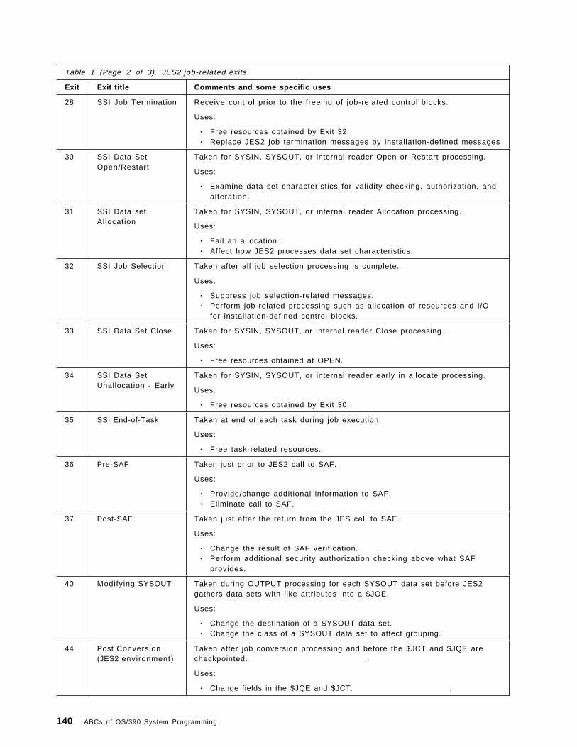
Table 1 (Page 2 of 3). JES2 job-related exits
Exit Exit title Comments and some specific uses
28 SSI Job Termination Receive control prior to the freeing of job-related control blocks.
Uses:
• Free resources obtained by Exit 32.• Replace JES2 job termination messages by installation-defined messages
30 SSI Data SetOpen/Restart
Taken for SYSIN, SYSOUT, or internal reader Open or Restart processing.
Uses:
• Examine data set characteristics for validity checking, authorization, andalteration.
31 SSI Data setAllocation
Taken for SYSIN, SYSOUT, or internal reader Allocation processing.
Uses:
• Fail an allocation.• Affect how JES2 processes data set characteristics.
32 SSI Job Selection Taken after all job selection processing is complete.
Uses:
• Suppress job selection-related messages.• Perform job-related processing such as allocation of resources and I/O
for installation-defined control blocks.
33 SSI Data Set Close Taken for SYSIN, SYSOUT, or internal reader Close processing.
Uses:
• Free resources obtained at OPEN.
34 SSI Data SetUnallocation - Early
Taken for SYSIN, SYSOUT, or internal reader early in allocate processing.
Uses:
• Free resources obtained by Exit 30.
35 SSI End-of-Task Taken at end of each task during job execution.
Uses:
• Free task-related resources.
36 Pre-SAF Taken just prior to JES2 call to SAF.
Uses:
• Provide/change additional information to SAF.• Eliminate call to SAF.
37 Post-SAF Taken just after the return from the JES call to SAF.
Uses:
• Change the result of SAF verification.• Perform additional security authorization checking above what SAF
provides.
40 Modifying SYSOUT Taken during OUTPUT processing for each SYSOUT data set before JES2gathers data sets with like attributes into a $JOE.
Uses:
• Change the destination of a SYSOUT data set.• Change the class of a SYSOUT data set to affect grouping.
44 Post Conversion(JES2 environment)
Taken after job conversion processing and before the $JCT and $JQE arecheckpointed. .
Uses:
• Change fields in the $JQE and $JCT. .
140 ABCs of OS/390 System Programming

Table 1 (Page 3 of 3). JES2 job-related exits
Exit Exit title Comments and some specific uses
46 NJE Transmission Taken for NJE header, trailer, and data set header during NJE jobtransmission.
Uses:
• Remove/add/change installation-defined sections to an NJE data areabefore transmission.
47 NJE Reception Taken for NJE header, trailer, and data set header during NJE job reception.
Uses:
• Remove/change installation-defined sections that were previously addedto an NJE data area.
48 Sysout unallocation- Late
More suitable then exit 34 when modifying SYSOUT characteristics oraffecting SPIN processing.
49 Job Queue WorkSelect
Taken whenever JES2 has located a pre-execution job for a device.
Uses:
• Provide an algorithm to accept or not accept a JES2-selected job• Control WLM initiator job selection.
Table 2. Some SMF job-related exits
Exit Exit title Comments and some specific uses
IEFUJV SMF Job Validation Receives control:
• Before each JCL statement is interpreted and• After all the JCL is converted and again• After all the JCL is interpreted.
IEFUJI SMF Job Initiation Receives control before a job on the input queue is selectedfor initiation.
Uses:
• Selectively cancel the job.
IEFUSI SMF Step Initiation Receives control before each job step is started (beforeallocation).
Uses:
• Limit the user region size.
IEFACTRT SMF Job Termination Receives control on the termination of each step or job.
Uses:
• Decide whether the system is to continue the job (forstep job)
• Decide whether SMF termination records are to bewritten to SMF data set.
IEFUJP SMF Purge Receives control when a job is ready to be purged from thesystem, after the job has terminated and all its sysouts havebeen written.
Uses:
• Selectively decide whether the SMF job purge record(type 26) is to be written to the SMF data set.
Chapter 3. Job Management 141

Figure 101. JES2 - Exits in conversion phase
3.4.2 JES2 - Exits in conversion phase
The visual shows the exit points in the conversion phase. The steps A and K are processed in theJES2 environment. The other steps are processed in the JES2 subtask environment. The reason forthe subtask environment is that the conversion process requires the reading of the JCL data set fromspool, reading JCL from PROCLIB, writing JCL images to spool, and the writing of C/I text to spool.These I/O operations cannot be accomplished in the maintask environment.
The conversion phase offers the only chance to have exit control over all of a job′s JCL. Although SMFexit IEFUJV is taken for each JCL and continuation statement, JES2 Exit 6 offers some advantages asfollows:
• The format of the C/I text is more structured.
• There is no continuation statement, only a single C/I text statement.
• All major syntax errors have been removed.
An SAF security environment can be used with the RACF FACILITY class to control the specification ofoptions within the JCL.
142 ABCs of OS/390 System Programming

Figure 102. JES2 - Exits on execution Phase
3.4.3 JES2 - Exits on execution Phase
The visual shows exits and their sequences for the execution phase. Job Selection is defined as theperiod starting with the initiator′s Subsystem Interface (SSI) call for job selection by class and endswith the JES2 message, $HASP373 JOB STARTED.
The visual shows services provided by the JES2 job selection (includes end-of-job functions) and theMVS Initiator.
Refer to OS/390 JES2 Installation Exits, SC28-1793, for all JES2 job-related exit scenarios.
Chapter 3. Job Management 143

Figure 103. JES2 start procedure
3.5 How to start JES2
JES2 can be started after the OS/390 system has been initialized. The OS/390 system automaticallystarts JES2 if your installation provides this capability. Otherwise, you must issue the STARTcommand to invoke a JCL procedure in SYS1.PROCLIB that starts JES2. JES2 initialization isperformed after JES2 has been started. Initiators will not accept work (process jobs) until JES2initialization is complete.
3.5.1.1 JES2 start procedure
To start the JES2 component, an installation must provide a subsystem cataloged JCL procedure(PROC). The PROC name can be a maximum of four characters. The PROC must be defined in theIEFSSNxx member of SYS1.PARMLIB.
The basic JCL procedure is shown in this visual. It contains an EXEC statement and five DDstatements. The EXEC statement parameters specify as follows:
P G M = Specify the name of the JES2 load module that resides in an authorized library.
T I M E = Specify ′NOLIMIT′ or 1440 to prevent system ABEND code 322.
P A R M = Specify JES2 start options. IBM suggests you specify NOREQ for the start parameters. WARMis the default. Table 3 on page 147 lists the JES2 start options available.
IBM recommends that you do not specify the REGION parameter to prevent any virtual storagelimitations in the JES2 address space. The DD statement parameters specify as follows:
144 ABCs of OS/390 System Programming

PROC00 Defines a default procedure library to be used for converting the JCL of batch jobs,time-sharing logons, and system tasks.
PROCxx (01-99) Can be used to define other user-cataloged procedure libraries that are associatedwith job classes by the JOBCLASS initialization statement or by the /*JOBPARMJES2 control statement.
HASPLIST Defines what is normally a dummy output data set, but you can modify thisstatement to permanently point to a specific device or data set.
HASPPARM Specifies the data set containing the initialization statements that will be used forJES2 initialization. With this statement, you can control all JES2 functions. Themajority of them can be changed dynamically using JES2 commands.
Chapter 3. Job Management 145
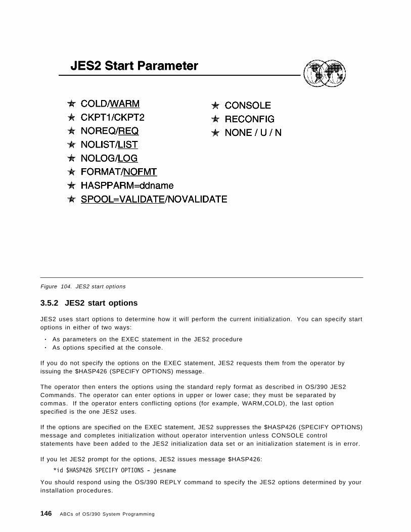
Figure 104. JES2 start options
3.5.2 JES2 start options
JES2 uses start options to determine how it will perform the current initialization. You can specify startoptions in either of two ways:
• As parameters on the EXEC statement in the JES2 procedure• As options specified at the console.
If you do not specify the options on the EXEC statement, JES2 requests them from the operator byissuing the $HASP426 (SPECIFY OPTIONS) message.
The operator then enters the options using the standard reply format as described in OS/390 JES2Commands. The operator can enter options in upper or lower case; they must be separated bycommas. If the operator enters conflicting options (for example, WARM,COLD), the last optionspecified is the one JES2 uses.
If the options are specified on the EXEC statement, JES2 suppresses the $HASP426 (SPECIFY OPTIONS)message and completes initialization without operator intervention unless CONSOLE controlstatements have been added to the JES2 initialization data set or an initialization statement is in error.
If you let JES2 prompt for the options, JES2 issues message $HASP426:
*id $HASP426 SPECIFY OPTIONS - jesname
You should respond using the OS/390 REPLY command to specify the JES2 options determined by yourinstallation procedures.
146 ABCs of OS/390 System Programming

REPLY id,options
Table 3 explains the JES2 start options. Read the rules following the table before attempting to specifystart options from the console.
If you respond to message $HASP426 with the $PJES2 command, JES2 will terminate.
Note: If you specify the NOREQ option, JES2 will automatically start processing following initialization.Otherwise, you must enter the $S command in response to the $HASP400 ENTER REQUESTS message tostart JES2 processing.
Table 3 (Page 1 of 2). JES2 Start Parameter
Option Explanation
FORMAT
NOFMT
FORMAT specifies that JES2 is to format all existing spool volumes. If you addunformatted spool volumes, JES2 automatically formats them whether FORMATis specified or not. With FORMAT, JES2 automatically performs a cold start.
Default: NOFMT specifies that JES2 is not to format existing spool volumesunless JES2 determines that formatting is required.
COLD
WARM
COLD specifies that JES2 is to be cold-started. All jobs in the system will bepurged and all job data on the spool volumes will be scratched.
Default: WARM specifies that JES2 is to continue processing jobs from wherethey were stopped. If the FORMAT option was also coded, then JES2 will ignorethe WARM specification and perform a cold start.
SPOOL=VALIDATE
NOVALIDATE
VALIDATE specifies that the track group map is validated on a JES2 all-memberwarm start.
Default: SPOOL=NOVALIDATE specifies that the track group map is not validatedwhen JES2 restarts.
NOREQ
REQ
NOREQ specifies that the $HASP400 (ENTER REQUESTS) message is to besuppressed and JES2 is to automatically start processing when initialization iscomplete.
Default: REQ specifies that the $HASP400 (ENTER REQUESTS) message is to bewritten at the console. This message allows you to start JES2 processing withthe $S command.
NOLIST
LIST
NOLIST specifies that JES2 is not to print the contents of the initialization dataset or any error flags that occur during initialization. If you specify NOLIST, JES2ignores any LIST control statements in the initialization data set. OS/390 JES2Initialization and Tuning Reference presents an example of an initialization dataset listing produced by using the list option.
Default: LIST specifies that JES2 is to print all the statements in the initializationdata set and any error flags that occur during initialization. (JES2 prints thesestatements if a printer is defined for that purpose when JES2 is started.) LISTwill not print any statements that follow a NOLIST control statement in theinitialization data set.
NOLOG
LOG
NOLOG specifies that JES2 is not to copy initialization statements or initializationerrors to the HARDCPY console. If you specify NOLOG, JES2 ignores LOGcontrol statements in the initialization data set.
Default: LOG specifies that JES2 is to honor any LOG statements in theinitialization data set.
CKPT1
CKPT2
Specifies what checkpoint data set JES2 must use for building the JES2 workqueues.
Default: If you do not specify, JES2 automatically determines which checkpointdata set to use.
Chapter 3. Job Management 147

Table 3 (Page 2 of 2). JES2 Start Parameter
Option Explanation
RECONFIG RECONFIG specifies that JES2 will use the checkpoint data set definitions asspecified on the CKPTDEF statement in the initialization data set. JES2 overridesany modifications to the checkpoint data set definitions previously made eitherby the $T CKPTDEF command or through the use of the checkpointreconfiguration dialog. Specifying RECONFIG will also cause JES2 to enter thereconfiguration dialog during initialization and issue message $HASP289 CKPT1AND/OR CKPT2 SPECIFICATIONS ARE REQUIRED.
If you previously reconfigured your checkpoint configuration through thecheckpoint reconfiguration dialog, the CKPTDEF statement definition may notcontain the most current checkpoint definition. Changes made through thecheckpoint reconfiguration dialog are not saved in the input stream data set.
HASPPARM=ddname HASPPARM=ddname specifies the name of the data definition (DD) statementthat defines the data set containing the initialization statements that JES2 is touse for this initialization.
Default: HASPPARM=HASPPARM specifies that JES2 is to be initialized using theinitialization statements in the data set defined by the HASPPARM DD statementin the JES2 procedure.
CONSOLE Causes JES2 to simulate receiving a CONSOLE initialization statement after allinitialization statements are processed. That is, if CONSOLE is specified, JES2will divert to the operator console for further parameter information after theinput stream data set has been exhausted.
NONE
U
N
NONE, U, or N character specifies that JES2 is to use all of the default startoptions. There is no difference between these three options. These options areequivalent. When NONE, U, or N is specified, JES2 uses the default start optionswhich are:
NOFMT
WARM
REQ
LIST
LOG
148 ABCs of OS/390 System Programming

Figure 105. Restarting JES2
3.5.3 Restarting JES2 with cold start option
Very few definitions, or redefinitions, of some JES2 facilities and resources require the JES2 system betotally shut down. JES2 must be restarted with a cold start to allow all component systems to beaware of the changed facilities and resources. The time to restart JES2 in this manner is based on thework in the system and, if not scheduled, causes a disruption in data processing services. All job datapreviously on the spool volumes is lost with cold start. You can avoid data loss by scheduling a spooloffload of the JES2 queues. In a MAS configuration, no other member can be active during a coldstart. Use of the FORMAT option causes a cold start.
An IPL must precede a JES2 cold start, unless JES2 was stopped with a $P JES2 operator command.
3.5.3.1 Warm startDuring a warm-start initialization, JES2 reads through its job queues and handles each job according toits status:
• Jobs in input readers are lost and must be reentered.
• Jobs in output (print/punch) are requeued and later restarted. The checkpoint for jobs on the 3800printer points to the end of the page being stacked at the time of the checkpoint. Jobs that weresent to the 3800 printer but that did not reach the stacker are reprinted from the checkpoint. If nocheckpoint exists, then it is reprinted from the beginning.
• Jobs in execution are either requeued for execution processing or are queued for outputprocessing.
Chapter 3. Job Management 149
• All other jobs remain on their current queues.
There are four ways in which a warm start can be performed in a multi-access spool configuration, asfollows:
1. All-member warm start
An all-member warm start is performed if a warm start is specified by the operator and JES2determines that no other members of the configuration are active or there is only one member inthe configuration. All in-process work in the MAS will be recovered. After an all-member warmstart, other members entering the configuration for the first time will perform a quick start.
2. Single-member warm start
This is performed when WARM is specified and others members of the configuration are active.The warm-starting member joins the active configuration and recovers only work in process on thatmember when it failed or was stopped.
3. Quick start
This is performed when you specified a warm start and JES2 determined that the job queue andjob output table do not need to be updated. In this case, the member being started is not the firstmember being started in the MAS. This occurs:
• After $P JES2 has been issued to quiesce the member. Because all work is quiesced, there isno need to update the job queue or job output table before restarting.
• After an all-member warm start has been performed and no work is waiting to be processed;therefore, the job and output queues are empty.
• When a $E MEM command was entered at a processor within the MAS configuration other thanthe member being started.
4. Hot start
This is a warm start of an abnormally terminated JES2 member without an intervening IPL. Whenit happens, all address spaces continue to execute as if JES2 had never terminated. JES 2validates (and rebuilds, when necessary) the job and output queues and the job queue index.Damaged or corrupted job output elements (JOEs) and job queue elements (JQEs) are placed onthe rebuild queue.
150 ABCs of OS/390 System Programming

Figure 106. Stopping JES2
3.6 Stopping JES2
There are instances when JES2 must be stopped and restarted either by a warm or cold start. Forexample, redefining the number of systems in a network job environment requires a warm start. Youcan stop and restart JES2 in a system at any time by using operator commands. This allows you to:
• Quiesce job processing in preparation for an orderly system shutdown.
• Restart JES2 to perform an initialization with different initialization parameter specifications.
You can dynamically change JES2 initialization statements by using $T operator for most parameters.Before stopping JES2 for the purpose of changing initialization statement parameters, refer to OS/390JES2 Initialization and Tuning Reference, SC28-1791. ,
To stop JES2, do the following:
1. Issue the $P command to stop all JES2 processing. System initiators, printers, punches, jobtransmitters, and SYSOUT transmitters will not accept any new work and will become inactive aftercompleting their current activity. However, new jobs will be accepted through input devices. Whenall TSO users log off, and all JES2 started tasks, logical initiators, printers, and punches completetheir current activities and become inactive, JES2 notifies you with the following message:
$HASP099 ALL AVAILABLE FUNCTIONS COMPLETE
2. Stop all started tasks.
Chapter 3. Job Management 151

3. Enter the $P JES2 command to withdraw JES2 from the system. If any jobs are being processed orany devices are active, the $P JES2 command is processed as a $P command and drains JES2work from the system.
If it is not possible or reasonable to drain the JES2 member (for example, due to large numbers oflines, jobs, and remotes; or, if you plan to restart JES2 using a hot start) you can specify:
$P JES2,ABEND
The ABEND parameter forces JES2 termination regardless of any JES2 or system activity. If thecheckpoint resides on a Coupling Facility structure and the member is processing a write request,JES2 issues the $HASP552 message and delays the $P command until the checkpoint write hascompleted.
If the $P JES2,ABEND command does not successfully terminate JES2, you can also specify theFORCE parameter. The $PJES2,ABEND,FORCE command results in a call to the recoverytermination manager (RTM) to terminate the JES2 address space. Because the FORCE parametercan cause unpredictable results, always attempt to enter the $P JES2,ABEND command first.
To withdraw JES2 from a system involved in cross-system activity, you can issue the $PJES2,QUICK command. Cross-system activity occurs when a user on one JES2 subsystemrequests a cross-system function from another JES2 subsystem within the same poly-JES2environment. This option deletes the control blocks for the request submitted by the user whorequested cross-system function. Before using the QUICK keyword on the $P JES2 command, youshould send a message to the user asking them to end their cross-system activity.
4. Issue the HALT EOD command. It ensures that important statistics and data records in storage arenot permanently lost.
152 ABCs of OS/390 System Programming

Figure 107. JES2 operations
3.7 JES2 operations
No large data processing system or subsystem can continuously operate independently of systemprogrammer or operator intervention. To help you maintain your overall work environment, JES2provides a set of commands that permits you to control the most of JES2 functions and devices underits control.
As your JES2 complex becomes more sophisticated, you might connect your system to others to form anetwork of systems. You can use operator commands to control the lines that connect the separatesystems, as well as to define the separate systems to yours. This is typically a very dynamicenvironment, as different systems are added or deleted from the network due to maintenance,hardware reconfiguration requirements, workload balancing, or the need to access a database at adifferent location. JES2 commands permit you to alter most of your original network definition, asrequired. Almost all JES2 initialization statements can be changed dynamically by JES2 operatorcommands.
Operator commands can be used to:
• Display status information and device definition.
• Start, stop, and halt devices under JES2′s control.
• Assign units to local printers, punches, card readers, and lines, or reassign units to these devices.
Chapter 3. Job Management 153
• Modify processing, such as: output definition, the dynamic alteration of the checkpoint definition,enabling installation-defined exits, offload devices, printer and punch characteristics, and jobcharacteristics.
• Add function and functional subsystems.
• Delete function, network systems, exits, and diagnostic traces.
Your installation can require that only certain operators can issue certain JES2 commands and/orrestrict commands coming in from RJE workstations, NJE nodes, or any other device. You can useRACF and customization techniques to limit the degree of control an individual or group can have overJES2 resources.
All JES2 commands are entered using standard OS/390 command interfaces such as an OS/390console or within the JES2 initialization data set. As the default, JES2 prefixes its commands andmessages with a dollar sign ($). For commands, the prefix character defines the scope of thecommand as being JES2 only; for messages, the prefix character is informational in that it designatesthat the message was issued by the JES2 component. You can change this symbol through theCONDEF initialization statement.
154 ABCs of OS/390 System Programming

Figure 108. Controlling the JES2 environment
3.7.1 Controlling the JES2 environment
The following commands are useful to control the JES2 environment:
• Start JES2 processing, $S
• Stop JES2 processing, $P
• Withdraw JES2 from the system, $P JES2
• Monitor local buffers, $T BUFDEF
• Monitor SMF buffers, $T SMFDEF
Chapter 3. Job Management 155

Figure 109. Controlling a JES2 MAS environment
3.7.2 Controlling a JES2 MAS environment
The following commands are useful to control your multi-access spool (MAS) environment:
• Display characteristics of the MAS, $D MASDEF
• Display the status of MAS members, $D MEMBER
• Control the MAS environment, $T MASDEF
• Display the checkpoint definition, $D CKPTDEF
• Control the checkpoint definition, $T CKPTDEF
156 ABCs of OS/390 System Programming

Figure 110. Controlling JES2 spooling
3.7.3 Controlling JES2 spooling
The following commands are useful to control the JES2 spool:
• Display spool volume usage, $D SPOOL
• Start a spool volume, $S SPOOL
• Control the JES2 spooling environment, $T SPOOLDEF
• Drain a spool volume, $P SPOOL
• Halt a spool volume, $Z SPOOL
Chapter 3. Job Management 157

Figure 111. Controlling JES2 jobs
3.7.4 Controlling JES2 jobs
The following commands are useful to control JES2 jobs:
• Release specified jobs, $A Job
• Cancel a job, $C Job
• Cancel output groups, $CO Job
• Display information about a specified job, $D Job
• Hold a specified job, $H Job
• List job output information, $L Job
• Release or cancel held output groups, $O Job
• Purge a job, $P Job
• Purge an output job, $PO Job
• Change a job′s class, scheduling priority, or member affinity, $T Job
• Set output characteristics, $T O
158 ABCs of OS/390 System Programming
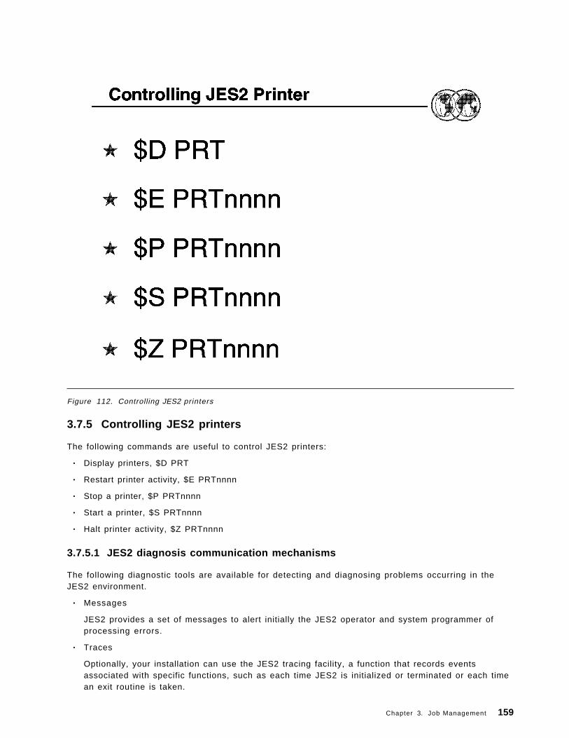
Figure 112. Controlling JES2 printers
3.7.5 Controlling JES2 printers
The following commands are useful to control JES2 printers:
• Display printers, $D PRT
• Restart printer activity, $E PRTnnnn
• Stop a printer, $P PRTnnnn
• Start a printer, $S PRTnnnn
• Halt printer activity, $Z PRTnnnn
3.7.5.1 JES2 diagnosis communication mechanisms
The following diagnostic tools are available for detecting and diagnosing problems occurring in theJES2 environment.
• Messages
JES2 provides a set of messages to alert initially the JES2 operator and system programmer ofprocessing errors.
• Traces
Optionally, your installation can use the JES2 tracing facility, a function that records eventsassociated with specific functions, such as each time JES2 is initialized or terminated or each timean exit routine is taken.
Chapter 3. Job Management 159

• IPCS
JES2 exploits the interactive problem control system (IPCS) facility to allow you to view theformatted contents of JES2 control blocks and dumps of system data necessary when diagnosingand recovering from processing errors.
160 ABCs of OS/390 System Programming

Figure 113. JES3
3.8 JES3
With the OS/390 MVS JES3 system, resource management and workflow management are sharedbetween MVS and its Job Entry Subsystem 3 (JES3) component. Generally speaking, JES3 doesresource management and workflow management before and after job execution, while MVS doesresource and workflow management during job execution.
JES3 considers job priorities, device and processor alternatives, and installation-specified preferencesin preparing jobs for processing job output. The features of the JES3 design include:
• Single-system image• Workload balancing• Availability• Control flexibility• Physical planning flexibility
This visual shows the JES3 topics discussee in this section.
Chapter 3. Job Management 161

Figure 114. JES3 configuration
3.8.1 JES3 configuration
JES3 runs on either one processor or on up to thirty-two processors in a sysplex. A sysplex is a set ofMVS systems communicating and cooperating with each other through certain multisystem hardwarecomponents and software services to process customer workloads.
In a sysplex, your installation must designate one processor as the focal point for the entry anddistribution of jobs and for the control of resources needed by the jobs. That processor, called theglobal processor, distributes work to the processors, called local processors.
It is from the global processor that JES3 manages jobs and resources for the entire complex, matchingjobs with available resources. JES3 manages processors, I/O devices, volumes, and data. To avoiddelays that result when these resources are not available, JES3 ensures that they are available beforeselecting the job for processing.
JES3 keeps track of I/O resources, and manages workflow in conjunction with the workloadmanagement component of MVS by scheduling jobs for processing on the processors where the jobscan run most efficiently. At the same time, JES3 maintains data integrity. JES3 will not schedule twojobs to run simultaneously anywhere in the complex if they are going to update the same data.
JES3 may be operated from any console that is attached to any system in the sysplex. From anyconsole, an operator can direct a command to any system and receive the response to that command.In addition, any console can be set up to receive messages from all systems, or a subset of the
162 ABCs of OS/390 System Programming

systems in the sysplex. Thus, there is no need to station operators at consoles attached to eachprocessor in the sysplex.
If you want to share input/output (I/O) devices among processors, JES3 manages the sharing.Operators do not have to manually switch devices to keep up with changing processor needs for thedevices.
The JES3 architecture of a global processor, centralized resource and workflow management, andcentralized operator control is meant to convey a single-system image, rather than one of separateand independently-operated computers.
JES3 runs in the following environments:
• Single-processor environment
• Multiprocessor environment
• Remote job processing environment
• JES3 networking environment
• APPC environment
A JES3 complex can involve any combination of these environments.
Chapter 3. Job Management 163

Figure 115. JES3 complex
3.8.2 JES3 complex
OS/390 uses the Job Entry Subsystem 3 (JES3) portion of the OS/390 System Product - JES3 to controlthe input, processing, and output of jobs. JES3 services the job processing requirements of one to 32physically connected OS/390 processors called mains. Viewed as a whole, the one- to 32-mainenvironment serviced by JES3 is called a complex.
JES3 has its own private address space in each of the mains in the complex. One main, the JES3global main, is in control of the entire complex. There must be a global main; if there is only one mainin the complex, that main is the global. In a complex with more than one main, the other mains inwhich JES3 resides are called local mains. There can be as many as 31 local mains.
JES3 is designed so that if the global fails, any properly-configured local within the complex canassume the function of the global through a process called dynamic system interchange (DSI). Thevisual illustrates the basic structure of a JES3 complex.
164 ABCs of OS/390 System Programming

Figure 116. JES3 in a single-processor environment
3.8.3 JES3 single processor
The visual shows JES3 in a single-processor environment, also known as a single-system sysplex.Besides the processor, two categories of I/O devices are shown:
• JES3 devices (those used by JES3)
• JES3- and MVS-managed devices (those used by jobs).
The spool device is a direct-access storage device (DASD) that is treated in a special way by JES3, soit is shown and explained separately.
In installations with one processor, the global processor, JES3 coexists in that processor with MVS andwith running jobs. In many respects, JES3 is treated like a job by MVS. (MVS handles JES3 in muchthe same way it handles the jobs it receives from JES3 for processing). JES3 becomes a processable″job″ during initialization, while jobs submitted to the system become processable by the actions ofJES3.
Chapter 3. Job Management 165

Figure 117. JES3 multiprocessing
3.8.4 Multi-system image
Multiprocessing is a way of doing work with two or more connected processors. In a multiprocessingenvironment, also known as a multisystem sysplex, JES3 allows up to 32 processors, also known asmains, to be configured into the complex. JES3 uses one processor (called the global) to do work andalso to distribute work to up to 31 other processors (called locals). Some of the advantages of runningJES3 in this environment are:
• Elimination of much of the overhead of scheduling work for and operating separate processors
• Sharing devices by processors, which means that the devices can be used more efficiently
• Movement of work to other processors, should one processor become overworked, needmaintenance, or need to be removed from the complex for any reason.
The global processor and the local processors communicate using the OS/390 cross-system CouplingFacility (XCF). JES3 devices (the devices from which JES3 reads jobs, and on which JES3 stores jobsawaiting processing, stores job output, and writes job output) are connected to the global processor.Some JES3 devices that write job output can also be connected to the local processors.
The visual shows a JES3 multiprocessing system that has three processors (that communicate via XCFsignalling). The global processor runs most of JES3, for it is from the global processor that JES3allocates resources to jobs and sends jobs to local processors for processing. In addition, JES3 canalso pass jobs to OS/390 in the global processor for processing.
166 ABCs of OS/390 System Programming

Each local processor has a complete OS/390 system and JES3 routines for spooling and forcommunication with the global processor. When OS/390 in a local processor needs a job, JES3 in thatlocal processor sends the job request to JES3 in the global processor via XCF signalling. JES3 in theglobal processor returns identifying information about a job, and JES3 in the local processor uses thatinformation to retrieve the job from the spool device.
If a problem arises on the global processor while JES3 is running, you can transfer global functions toa local processor. This transfer is called dynamic system interchange (DSI). The processor youchoose must be capable of assuming the same workload as the previous global.
3.8.5 Availability
If a problem develops with the global processor, you can have one of the other processors assume theglobal functions. (Operators have JES3 commands to cause the switch.) Jobs running on otherprocessors, including the one to become the new global processor, will usually be unaffected (exceptfor a waiting period until global activities are resumed).
If part of JES3 fails, JES3 collects failure symptoms, records error data, and attempts recovery. Allmajor JES3 components are protected by at least one special JES3 recovery routine. If recovery isunsuccessful, the failing component gets insulated from the rest of JES3, resources are freed, and thefailing component will not be used again. If the component is not critical to overall JES3 processing,complete JES3 failure may be avoided.
3.8.6 Workload balancing
JES3 balances workload among processors by considering the resource requirements of jobs. Themethod JES3 uses is the same whether one or several processors make up the configuration. Thus,addition of another processor does not mean a new operational and scheduling environment.
Chapter 3. Job Management 167

Figure 118. Spooling to collect job output
3.8.7 Spool devices
Most multiprocessing systems use shared data storage. In JES3 the spool device becomes the shareddata storage. Thus, besides being a buffer (as for single-processor systems), in multiprocessingsystems the spool device becomes a collection point for data to be distributed to individual processors.Also, the spool device becomes a collection point for data coming from local processors routed to JES3output devices connected to the global processor.
3.8.8 Control flexibility
Operating systems must be easy to control. Internal complexity must be offset by features that makethe systems easy to operate, to monitor, and to change. JES3 has designed-in features for operators,application programmers, and system programmers:
• Operators have special JES3 commands. Some commands activate programs to handle I/Odevices, while others obtain or change the status of jobs being processed. With multipleprocessing-unit systems, JES3 operators have less to do than for an equal number of individualsystems, because they can control the entire complex from a central point, and because JES3decides where and when jobs will be processed.
JES3 applies installation policies, as defined in the JES3 initialization stream, to perform jobscheduling, thus freeing the operator from this task.
Even though JES3 handles job flow control, there are operational controls in JES3 for the operatorto use at his or her discretion to override JES3 decisions, and to take control in unusual situations.
168 ABCs of OS/390 System Programming
• Application programmers have special JES3 control statements (similar to JCL statements). Thereare control statements to make some jobs run only after successful (or unsuccessful) processing ofother jobs, and for specifying the time of day, week, month, or even the year when jobs should run.
• System programmers have special JES3 initialization statements to define the way JES3 is tomanage devices and jobs. Operators or application programmers can override many of theseinitialization options on a job-by-job basis. JES3 gives system programmers a unique way ofsetting installation policy for device and job management. They define separate groups ofprocessing rules. Application programmers select and apply the groups of rules in various ways toindividual jobs.
Where JES3 does not provide the exact function that your complex requires, such as special printingrequirements, the system programmers can write their own routines and make them part of the JES3program. This is done through installation exits provided with JES3 and through dynamic supportprograms that can be added to JES3. For diagnostic purposes, JES3 provides traces and dumps.Traces are copies of data made during normal processing to help monitor activity in the system, anddumps are copies of data made at times of failure.
Chapter 3. Job Management 169

Figure 119. JES3 job f low
3.8.9 JES3 phases of job processing
Following are the first two phases of processing for a job in a JES3 system:
• Input service
JES3 initially reads all jobs into the global and assigns, to each job, a unique JES3 job numberfrom the available job number pool. Jobs can be submitted from a locally-attached tape, disk, orcard reader. In addition, jobs can be submitted from remote job processing (RJP) workstations,time-sharing option (TSO/E) terminals, other systems in a job entry network, or by the internalreader.
START and MOUNT commands and TSO/E LOGONs cause jobs to be started from predefinedprocedures. Input service processes the JCL created for these jobs in the same manner as anyother standard job.
Jobs initially placed on direct-access storage devices (DASD) and subsequently analyzed by JES3input service are placed on the JES3 spool.
• Converter/interpreter processing (JCL conversion)
JES3 chooses the address space where it converts the job′s JCL. The selected address spacethen reads the job′s JCL from spool and converts and interprets the JCL. During this processing,JES3 flushes any job with JCL errors and determines the job-referenced data sets that requirevolume mounting. JES3 passes the information about the required resources to the JES3 maindevice scheduler (MDS) if a job requires devices, volumes, or data sets.
170 ABCs of OS/390 System Programming

Figure 120. JES3 job f low
3.8.10 JES3 phases of job processing
After the first two phases where jobs are entered into the system and then passed through theconverter and interpreter, the next phases are:
• Main device scheduling (job resource management)
MDS ensures that resources (devices, volumes, and data sets) needed by the job are allocatedbefore the job processes. MDS sends fetch messages to the tape and disk libraries and mountmessages to the setup operators to mount the volumes needed.
• Generalized main scheduling (job selection)
JES3 schedules the job for processing based on specifications determined by the installation.
• Processing (main service - job execution)
Jobs can run on the global or a local. OS/390 controls the job during this phase. Duringprocessing, output generated by the job is usually written to the JES3 spool.
• Output processing
Once processing is complete, JES3 processes the job′s output data from the JES3 spool. Outputdata sets are printed and punched by JES3 output service when an available device matches thedata set′s requirements, such as forms, carriage forms control buffer (FCB), and train. JES3 outputservice informs the operator of any setup requirements of the data sets. The devices involved canbe either local or remote, as defined by the job.
• Purge processing
Chapter 3. Job Management 171

After output processing is complete, the purge function releases all spool space associated withthe completed job.
3.8.10.1 JES3 from a system programmer ′s point of view
One way of visualizing JES3 is as a control program that performs job entry and job exit services.Another way of visualizing JES3 is as a language. Saying that JES3 is a control program is analogousto saying FORTRAN is a compiler. In reality, there is a FORTRAN language and a FORTRAN compiler.Similarly, there is a JES3 language and there is a JES3 program. Just as a FORTRAN programmeruses the FORTRAN language to define work the compiler is to do, JES3 system programmers use theJES3 language to define the work that JES3 is to do.
The JES3 language is made up of initialization statements, control statements, and commands.Operators and application programmers use parts of the language, but it is system programmers whodefine the total JES3 environment. Often, what is specified on JES3 initialization statements can beoverridden with JES3 commands or control statements. While system programmers may notthemselves use commands or control statements, they may have to instruct operators or applicationprogrammers on when and how they should be used.
A further level of defining how JES3 should do its work comes in the form of installation exits suppliedwith JES3. For example, in the area of controlling the print output from jobs, a system programmercan:
• Define initial values in the initialization stream
• Allow the operator to make certain modifications to the initial values
• Write an installation exit routine to further modify or control what should happen to the output.
172 ABCs of OS/390 System Programming

Figure 121. JES3 commands
3.8.11 JES3 operator control
Commands are requests you make to the system. You can use commands to control devices, tochange specifications previously made to the system, or to display information about the operator′sconsole. The first element of a command is a prefix that informs JES3 that a command is beingentered. The default JES3 command prefix is the character (*).
These are the basic JES3 commands and their purposes:
• *INQUIRY commands are used to request information. No action will be taken except that therequested information will be displayed.
• *MODIFY commands are used to change specifications given in jobs or previous commands, orduring initialization.
• *CALL, *START, *RESTART, *CANCEL, and *FAIL commands are used to control dynamic supportprograms (DSPs), such as utilities.
• *VARY commands and the *MODIFY,V command are used to control devices and other JES3resources.
• *SWITCH and *FREE commands are used exclusively to control RJP consoles.• *MESSAGE commands are used to communicate with other consoles and with remote nodes.• *SEND commands are used to route commands to a remote node.• *DUMP and *RETURN commands are used to end JES3.• *TRACE command is used to trace certain JES3 events.
Chapter 3. Job Management 173

Figure 122. Controlling JES3 jobs
3.8.12 Controlling JES3 jobs
Use the *MODIFY,J= or the *F,J= command to:
• Hold a job, *F,J=nnnn H
• Release a job, *F,J=nnnn R
• Cancel a job, *F,J=nnnn C or CP or CO
• Change a job′s pr ior i ty, *F,J=nnnn P=nn
• Change a job′s job class, *F,J=nnnn C=class
• Change a job′s JESMSGLG logging status, *F,J=nnnn LOG or NOLOG
Use the *MODIFY,Q or *F,Q command to:
• Hold or release all the jobs in the JES3 job queue, *F Q H or R
• Hold or release jobs of a designated priority, *F Q P=nnn H or R
174 ABCs of OS/390 System Programming

Figure 123. Managing output service jobs
3.8.13 Managing output service jobs
Use the *INQUIRY,U or the *I,U command to display job output in a JES3 system. The job output canbe at various places within the system and your selection of the proper ″Q = ″ keyword value on the*INQUIRY,U command dictates what output you want.
The choices are generally the following:
• *INQUIRY,U,Q=BDT
To display SNA/NJE job output.
• *INQUIRY,U,Q=HOLD
To display job output on the HOLD queue.
• *INQUIRY,U,Q=WTR
To display job output on the WTR service queue.
• *INQUIRY,U
To display job output on the WTR service queue.
The commands may have a length of 126 characters if the command is issued from an input devicethat permits that command length.
Chapter 3. Job Management 175

Figure 124. JES3 start procedure
3.8.14 How to start JES3
JES3 runs as a started task in the OS/390 environment. Therefore, OS/390 must be active before youcan start JES3. Moreover, JES3 must be active on the global before you can start JES3 on the localmains.
The required JES3 procedure dd statements are explained as follows:
IEFPROC Specifies the name of the JES3 job step task, load module IATINTK.
CHKPNT and CHKPNT2 Define the the JES3 checkpoint data set(s). At least one of the twocheckpoint data sets must be allocated and cataloged prior to JES3operation. Each checkpoint data set must be allocated as a singleextent which begins and ends on a cylinder boundary. The size ofeach data set should be at least 2 cylinders on a 3380, 3390 or 9345spool volume.
JES3JCT Defines the JES3 job control table (JCT) data set. This data set mustbe allocated and cataloged prior to JES3 operation. The data set mustbe large enough to accommodate the maximum number of JCT recordsto be allocated concurrently during normal system operation.
Spool1 and Spoolnn Define the spool data sets. The installation selects the ddnames anddata set names for these statements. The ddname for this statementmust be the same ddname specified on the BADTRACK, FORMAT, or
176 ABCs of OS/390 System Programming

TRACK initialization statements. Spool data sets must be allocatedand cataloged prior to JES3 operation.
JES3OUT Defines the data set upon which the JES3 initialization stream andinitialization error messages are printed. This data set is de-allocatedafter initialization completes You can tailor the block size (BLKSIZE)and logical record length (LRECL) values to improve performance. Thevalues you can specify are device-dependent.
IATPLBST Defines the installation′s standard procedure library.
JES3IN Defines the data set containing the JES3 initialization stream. Thisdata set must be a blocked or unblocked partitioned data set. In ourexample, the initialization stream is read from SYS1.PARMLIB(memberJES3IN00).
Chapter 3. Job Management 177

Figure 125. JES3 initialization deck
3.8.15 JES3 initialization deck
Here are the required JES3 initialization statements:
• DEVICE,DTYPE=SYSMAIN,JNAME=main1,JUNIT=(,main2,, ¬ OFF|ON],...)
Use this form of the DEVICE statement (there are two other forms of the DEVICE statement) todefine the initial status of mains in a JES3 complex. You must code one of these DEVICEstatements for each main on every processor in the complex, as follows:
DEVICE,DTYPE=SYSMAIN,JNAME=SY1,JUNIT=(,SY1,,ON,)
• ENDINISH
Use the ENDINISH statement to identify the end of the initialization statements in the initializationstream.
• ENDJSAM
Use the ENDJSAM initialization statement to indicate the end of the JES3 spool initializationstatements.
• FORMAT,DDNAME=ddname,SPART=partitionname {,STT=(cylnum,cylnum)}{,STTL=(cylnum,numtrkgps)}
Use the FORMAT statement to specify formatting for a data set residing on a direct-access spoolvolume during initialization. Specify this statement only when introducing an unformatted volumeinto a JES3 system or when you change the BUFSIZE parameter on the JES3 BUFFER initializationstatement as follows:
178 ABCs of OS/390 System Programming

FORMAT,DDNAME=SPOOL1,STT=(30,31),SPART=PART1The corresponding DD statement in the JES3 start procedure is://SPOOL1 DD DSN=dsn,DISP=OLD,UNIT=SYSDA,VOL=SER=xxxxxx
• MAINPROC,NAME=main,SYSTEM=JES3,FIXPAGE=,ID=msgprefix,MDEST=,PRTPAGE=,RID=,SELECT=,SID=,SPART=partit ionname,TRKGRPS=,USRPAGE=
Use the MAINPROC initialization statement to define a uniprocessor or a multiprocessor as a JES3main. The initialization stream must include one MAINPROC statement for each main that youwish to define to JES3. Each MAINPROC statement must have a DEVICE statement that specifiesDTYPE=SYSMAIN associated with it.
The NAME=main specifies the name of a JES3 main. The name should match the purpose of themain, or at least the hardware it is using. You also use this name in operator commands and inthe JES3 CLASS, DEVICE, GROUP, MSGROUTE, and SETACC initialization statements to refer tothe main. It must be the first or secound parameter on the statement.
The SPART=partitionname specifies the spool partition that JES3 is to use for jobs that execute onthe main defined by this statement. To specify the default spool partition, omit the SPARTparameter.
• TRACK,DDNAME=ddname,SPART=partitionname {,STT=(cylnum,cylnum)}{,STTL=(cylnum,numtrkgps)}
Use the TRACK initialization statement to replace a corresponding FORMAT statement in aninitialization stream after the spool data set specified by the FORMAT statement has beenformatted. The TRACK statement indicates that the corresponding data set has been formatted.
TRACK,DDNAME=SPOOL1TRACK,DDNAME=SPOOL2Associated DD statements in the JES3 procedure://SPOOL1 DD DSN=dsn,DISP=OLD,UNIT=3330,VOL=SER=xxxxxx//SPOOL2 DD DSN=dsn,DISP=OLD,UNIT=3330,VOL=SER=MVSRW2
Depending on how your OS/390 initial program load (IPL) procedures are set up, JES3 can be startedautomatically or you can start JES3 manually by entering an OS/390 START command from the masterconsole. The manual method allows you to determine if the IPL and system configuration conditionsare acceptable before starting JES3. If the JES3 subsystem definition in the IEFSSNxx parmlib memberspecifies the NOSTART subparameter, JES3 must be started manually. Otherwise JES3 will startautomatically.
Chapter 3. Job Management 179

Figure 126. JES3 start parameter
3.8.16 JES3 start parameter
The types of starts and restarts for the JES3 global processor are shown on the visual. You must usea cold start when starting JES3 for the first time. For subsequent starts (restarts), you can use any oneof the start types, depending on the circumstances at the time. Thus, the other types of starts areactually restarts.
JES3 initialization statements are read as part of cold start, warm start, and hot start with refreshprocessing. If JES3 detects any error in the initialization statements, it prints an appropriate diagnosticmessage on the console or in the JES3OUT data set. JES3 ends processing if it cannot recover fromthe error. In this case, you must notify the system programmer to ensure that the error is correctedbefore restarting JES3.
JES3 configuration and processing options are specified with the initialization statements. Becausemany options affect the overall performance of the system, initialization statements must be providedby your system programmer. Starting a JES3 on a local main you can use the ROUTE command tostart JES3 on all the local processors, once JES3 global initialization is complete, for example:
ROUTE *OTHER,S JES3
Use a local start to restart JES3 on a local main after a normal shutdown on the local, after JES3 endsdue to a failure in either the local JES3 address space or OS/390, or after partitioning a multiprocessor.You must also start each local main after you perform a cold start or any type of warm start on theglobal or after you use a hot start to remove or reinstate a spool data set on the global processor.
180 ABCs of OS/390 System Programming
You can perform a local start any time the global is active. Local start processing uses theinitialization stream placed on the spool data sets during global main initialization.
Note: Do not start a main if another main having the same name is active in the complex.
Before you begin, be sure that all spool data sets available to the global are also available to thislocal.
If you are performing an IPL of the local main and the MSTRJCL contains the automatic STARTcommand, the command is displayed on your console immediately after the OS/390 master scheduleris initialized. You can enter the OS/390 command:
START JES3
The first message from JES3 is:
IAT3040 STATUS OF JES3 PROCESSORS IN COMPLEXmain(status) (,main(status)...)
A series of entries on the following lines of the message contains the name of each main followed by acode for that main′s status as recorded in the complex status record (CSR). During a start for thesystem, this entry (the status of the global) is:
main< >On subsequent starts, this entry could be:main<IN>
This indicates that the previous start ended abnormally during initialization; this main is still recordedin the CSR as being in initialization as follows:
main<UP>
This main is recorded in the CSR as currently being active (up). Consult with the system programmerbefore continuing with a cold start.
Next, JES3 issues the following message:
nn IAT3011 SPECIFY JES3 START TYPE:(C, L, H, HA, HR, HAR, W, WA, WR, WAROR CANCEL)
To continue the start, enter the appropriate letters shown in the message, as follows:
R nn,CTo cancel the start, enter:
R nn,CANCEL
Note: Because cold start processing involves reinitializing the spool and losing all jobs, JES3 issuesthe following message requiring you to confirm your request for a cold start before JES3 takesirreversible action:
nn IAT3033 CONFIRM JES3 COLD START REQUEST (U) OR CANCEL
To continue the cold start, enter:
R nn,U
To cancel the cold start, enter:
R nn,CANCEL
Any other reply restarts the sequence, beginning with message IAT3011.
Chapter 3. Job Management 181

After JES3 initialization has finished, you should start the job segment scheduler (JSS). You start jobscheduling after JES3 issues message IAT3100 notifying you that initialization processing is completeon the global:
IAT3100 JES3 xxxxx SYSTEM type START ON yyyy.ddd AS main
where xxxxx is the release level of JES3; type is COLD, WARM, or HOT; yyyy.ddd is the Julian date;and main is the JES3 name of the main.
Before starting job scheduling, you can use JES3 commands to cancel jobs, change the status of jobs,and change the status of devices. During a hot start with analysis, you can release jobs in spool holdstatus after reinstating a spool data set that contains data for the jobs, and you can vary devices onlineor offline. You can make adjustments for any system data that might have been lost during the restart.You can also make any changes to the system that were made before a hot start or a warm start butdid not remain in effect after the restart.
When you are satisfied that the system is ready to begin processing, enter a *START,JSS command tostart job scheduling:
*START,JSS
After you enter the *START,JSS command, ensure that the global is varied online to JES3. If it is not,enter the *(MODIFY,)V,main,ON command to vary the processor online, ensuring that the subsysteminterface, the OS/390 system commands, and the system log are initialized. JES3 then issues thefollowing message:
IAT2645 ***** main CONNECT COMPLETE *****
If you do not want the global to run jobs, you can now vary the main offline to JES3 scheduling with the*(MODIFY,)V,main,OFF command. At this point, you can resubmit any jobs that were canceled orwhose processing was altered as a result of the restart.
3.8.17 How to stop JES3
Stopping local processors
Before you remove a local main for maintenance or other reasons, allow processing jobs to completenormally. Use the following steps:
1. Enter a *F, V,main,OFF command for the local main to prevent JES3 from scheduling any furtherjobs on the processor.
2. Enter the *RETURN command with the proper password to end JES3 after all jobs on the local mainhave completed processing.
3. Enter the HALT EOD command on the local main to ensure that important statistics and datarecords in storage are not permanently lost.
Your installation may not want to wait for all jobs to complete normally, for example:
• Jobs will not end due to system problems (hardware and software)
• An IPL or JES3 restart is scheduled to take place at a predetermined time and jobs will not be ableto complete. In this case, you must make the decision to delay the IPL or to cancel the jobs.
Note: Enter the HALT EOD command only if you are performing an IPL or SYSTEM RESET, not torestart JES3.
Stopping the global processor
182 ABCs of OS/390 System Programming

Before stopping the global, you should stop the local mains as described before. You should stop allJES3 processing by entering the *F,Q,H command, which puts all jobs in hold status before stoppingJES3. System initiators, printers, and punches do not begin any new work and become inactive aftercompleting their current activity. Jobs in JES3 queues remain in their current position.
You should also queue the system log for printing by entering the WRITELOG command. This preventslog messages from being lost if you later restart JES3 with a hot start.
Once all system activity has completed, enter the *RETURN command to end JES3.
*RETURN,password,FSS=fssname -or-*RETURN,password,FSS=ALL -or*RETURN,password,FSS=NONE
After you enter the *RETURN command, enter the HALT EOD command to ensure that importantstatistics and data records in storage are not permanently lost. As a result of this command, theinternal I/O device error counts are stored in the SYS1.LOGREC data set; the SMF buffers are emptiedonto one of the SYS1.MANx data sets; and the system log, if still active, is closed and put on the printqueue. When these actions are complete, the system issues message IEE334I, stating that the HALTEOD operation was successful.
Chapter 3. Job Management 183
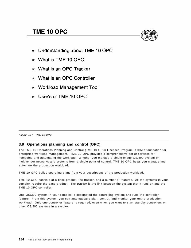
Figure 127. TME 10 OPC
3.9 Operations planning and control (OPC)The TME 10 Operations Planning and Control (TME 10 OPC) Licensed Program is IBM′s foundation forenterprise workload management. TME 10 OPC provides a comprehensive set of services formanaging and automating the workload. Whether you manage a single-image OS/390 system ormultivendor networks and systems from a single point of control, TME 10 OPC helps you manage andautomate the production workload.
TME 10 OPC builds operating plans from your descriptions of the production workload.
TME 10 OPC consists of a base product, the tracker, and a number of features. All the systems in yourcomplex require the base product. The tracker is the link between the system that it runs on and theTME 10 OPC controller.
One OS/390 system in your complex is designated the controlling system and runs the controllerfeature. From this system, you can automatically plan, control, and monitor your entire productionworkload. Only one controller feature is required, even when you want to start standby controllers onother OS/390 systems in a sysplex.
184 ABCs of OS/390 System Programming

3.9.1 Who uses TME 10 OPC• The scheduler maintains the current and future production processing across your enterprise.
− Automatically scheduling all production workload activities.
− Automatically resolving the complexity of production workload dependencies and driving thework in the most efficient way.
− Supporting the simulation of future workloads on the system. The scheduler can evaluate, inadvance, the effect of changes in production workload volumes or processing resources.
− Giving a real-time view of the status of work as it flows through the system so that thescheduler can quickly:
- Respond to customer queries about the status of their work.
- Identify problems in the workload processing.
− Providing facilities for manual intervention.
− Managing many workload problems automatically. The TME 10 OPCproduction-workload-restart facilities, hot standby, automatic recovery of jobs and started tasks,and dataset cleanup provide the scheduler with comprehensive error- anddisaster-management facilities.
− Providing a log of changes to the TME 10 OPC production workload data through the audit-trailfacility. This assists the scheduler in resolving problems caused by user errors.
− Managing unplannable work.
• The operations manager uses the reporting, planning, and control functions in:
− Improving the efficiency of the operation.
− Improving control of service levels and quality.
− Setting service level agreements for end-user applications and for services provided.
− Improving relationships with end-user departments.
− Increasing the return on your IT investment.
− Developing staff potential.
• The Shift Supervisor uses TME 10 OPC especially in multisystem complexes, where local andremote systems are controlled from a central site. Also it can help the shift supervisor in:
− Monitoring and controlling the flow of production work through multisystem complexes.
− Controlling the use of mountable devices.
− Separating information about work status from system and other information.
− Providing end users with status information directly.
− Managing the workload if a system failure occurs.
− Making changes to the current plan in response to unplanned events, such as equipmentfailures, personnel absences, and rush jobs.
• The application programmer . The TME 10 OPC user-authority checking enables applicationdevelopment groups to use all the planning and control functions of TME 10 OPC in parallelwith--but in isolation from--production systems and services. For the application programmer, itcan be a valuable tool for application development staff when they are:
− Packaging new applications for regular running
− Testing new JCL in final packaged form
− Testing new applications and changes to existing ones
Chapter 3. Job Management 185

− Restarting or rerunning unsuccessful jobs.
• The console operators can be freed from the these time-consuming tasks:
− Starting and stopping started tasks.
− Preparing JCL before job submission.
− Submitting jobs.
− Verifying the sequence of work.
− Reporting job status.
− Performing dataset cleanup in recovery and rerun situations.
− Responding to workload failure.
− Preparing the JCL for step-level restarts.
• The workstation operators gets help in:
− Providing complete and timely status information.
− Providing up-to-date ready lists that prioritize the work flow.
− Providing online assistance in operator instructions.
• The end users and help desks can be informed about the status of workload processing. They canuse the ISPF dialogs or the Workload Monitor/2 to check the status of the processing of theirapplications themselves, from a personal workstation. End users can make queries using theWorkload Monitor/2 without having to be familiar with TME 10 OPC, ISPF, or TSO, and withouthaving to be logged on to a local system. The Workload Monitor/2 also provides alerts that canautomatically advise end users when their work has completed or ended in error. The help deskcan use the Workload Monitor/2 in the same way to answer queries from end users about theprogress of their workload processing.
186 ABCs of OS/390 System Programming

Figure 128. TME 10 OPC platforms
3.9.2 TME 10 OPC platformsThe Tivoli Management Environment 10 Operations Planning and Control for OS/390 (TME 10 OPC) isthe state-of-the-art production workload manager, designed to help you meet your present and futuredata processing challenges. Its scope encompasses your entire enterprise information system,including heterogeneous environments.
Pressures on today′s DP environment are making it increasingly difficult to maintain the same level ofservices to customers. Many installations find that their batch window is shrinking. More critical jobsmust be finished before the morning online work begins. Conversely, requirements for the integratedavailability of online services during the traditional batch window put pressure on the resourcesavailable for processing the production workload. More and more 7/24 (7 days a week, 24 hours a day)is not only a DP objective but a requirement.
Users and owners of DP services are also making more use of batch services than ever before. Thebatch workload tends to increase each year at a rate slightly below the increase in the onlineworkload. Combine this with the increase in data usage by batch jobs, and the end result is asignificant increase in the volume of work.
Furthermore, there is a shortage of people with the required skills to operate and manage increasinglycomplex DP environments. The complex interrelationships between production activities--betweenmanual and machine tasks--have become unmanageable without a workload management tool.
TME 10 OPC provides leading-edge solutions to problems in production workload management. It canautomate, plan, and control the processing of your enterprise ′s entire production workload, not just the
Chapter 3. Job Management 187

batch subset. TME 10 OPC functions as an “automatic driver” for your production workload tomaximize the throughput of work, and optimize your resources, but also allows you to intervenemanually as required.
When TME 10 OPC interfaces with other system management products, it forms part of an integratedautomation and systems management platform for your DP operation.
TME 10 OPC forms operating plans based on user descriptions of the operations department and itsproduction workload. These plans provide the basis for your service level agreements and give you apicture of the production workload at any point in time. You can simulate the effects of changes inyour production workload and in resource availability by generating trial plans.
Good planning is the cornerstone of any successful management technique. Effective planning alsohelps you maximize return on your investments in information technology.
TME 10 OPC automates, monitors, and controls the flow of work through your enterprise′s entire DPoperation--on both local and remote systems. From a single point of control, TME 10 OPC analyzes thestatus of the production work and drives the processing of the workload according to installationbusiness policies. It supports a multiple end-user environment, enabling distributed processing andcontrol across sites and departments within your enterprise.
188 ABCs of OS/390 System Programming

Figure 129. OS/390 OPC Configuration
3.9.3 What is a TME 10 OPC TrackerA tracker is required for every controlled OS/390 system in an TME 10 OPC configuration. Thisincludes, for example, local controlled systems within shared DASD or sysplex configurations.
The tracker runs as an OS/390 subsystem and interfaces with the operating system (through JES2 orJES3, and SMF), using the subsystem interface and the operating system exits. The tracker monitorsand logs the status of work, and passes the status information to the controller via shared DASD, XCF,or ACF/VTAM.
You can exploit the OS/390 cross-system Coupling Facility (XCF) to connect your local OS/390 systems.Rather than being passed to the controlling system via shared DASD, work status information ispassed directly via XCF connections. XCF lets you exploit all of TME 10 OPC′sproduction-workload-restart facilities and its hot standby function.
The tracker on a remote OS/390 system passes status information about the production work inprogress to the controller on the TME 10 OPC controlling system. All communication between TME 10OPC subsystems on controlling and remote systems is done via ACF/VTAM.
TME 10 OPC lets you link remote systems using ACF/VTAM networks. Remote systems are frequentlyused locally “on premises” to reduce the complexity of the DP installation.
Every controlled AS/400 system needs the Tracker Agent for OS/400 feature installed. When thisfeature is used, status information and job logs for the production workload are passed back to thecontrolling OS/390 system using APPC services. The TME 10 OPC controller submits jobs and
Chapter 3. Job Management 189
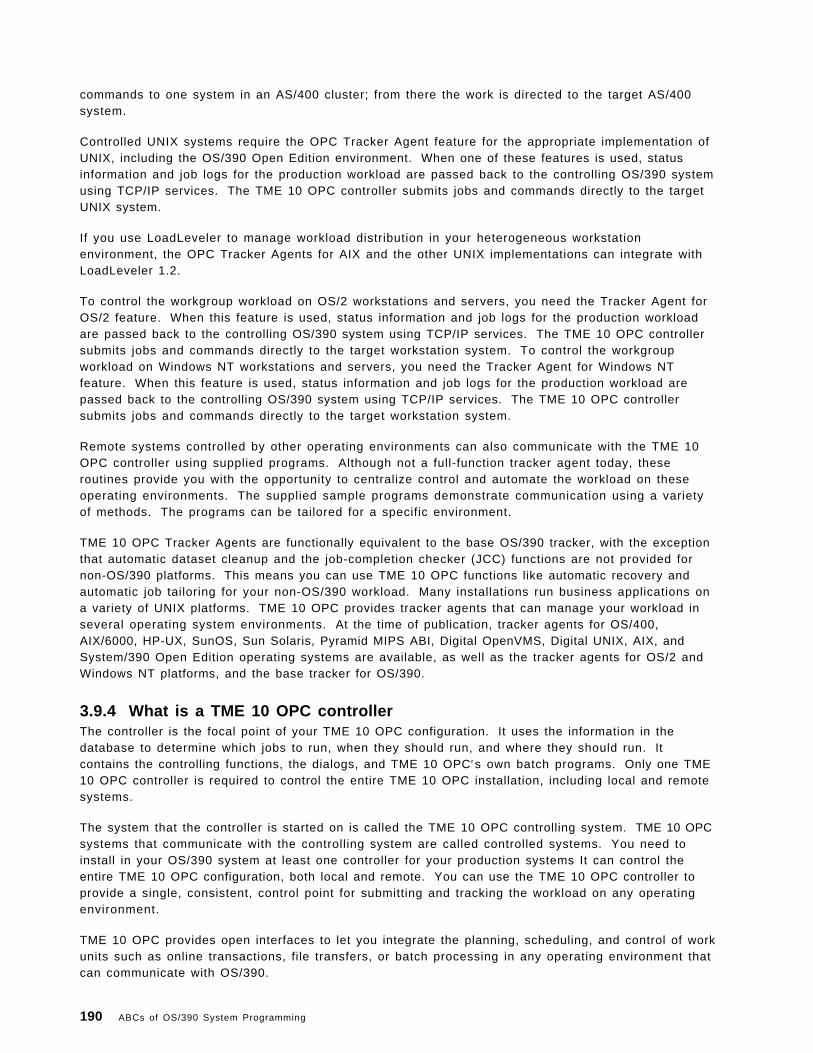
commands to one system in an AS/400 cluster; from there the work is directed to the target AS/400system.
Controlled UNIX systems require the OPC Tracker Agent feature for the appropriate implementation ofUNIX, including the OS/390 Open Edition environment. When one of these features is used, statusinformation and job logs for the production workload are passed back to the controlling OS/390 systemusing TCP/IP services. The TME 10 OPC controller submits jobs and commands directly to the targetUNIX system.
If you use LoadLeveler to manage workload distribution in your heterogeneous workstationenvironment, the OPC Tracker Agents for AIX and the other UNIX implementations can integrate withLoadLeveler 1.2.
To control the workgroup workload on OS/2 workstations and servers, you need the Tracker Agent forOS/2 feature. When this feature is used, status information and job logs for the production workloadare passed back to the controlling OS/390 system using TCP/IP services. The TME 10 OPC controllersubmits jobs and commands directly to the target workstation system. To control the workgroupworkload on Windows NT workstations and servers, you need the Tracker Agent for Windows NTfeature. When this feature is used, status information and job logs for the production workload arepassed back to the controlling OS/390 system using TCP/IP services. The TME 10 OPC controllersubmits jobs and commands directly to the target workstation system.
Remote systems controlled by other operating environments can also communicate with the TME 10OPC controller using supplied programs. Although not a full-function tracker agent today, theseroutines provide you with the opportunity to centralize control and automate the workload on theseoperating environments. The supplied sample programs demonstrate communication using a varietyof methods. The programs can be tailored for a specific environment.
TME 10 OPC Tracker Agents are functionally equivalent to the base OS/390 tracker, with the exceptionthat automatic dataset cleanup and the job-completion checker (JCC) functions are not provided fornon-OS/390 platforms. This means you can use TME 10 OPC functions like automatic recovery andautomatic job tailoring for your non-OS/390 workload. Many installations run business applications ona variety of UNIX platforms. TME 10 OPC provides tracker agents that can manage your workload inseveral operating system environments. At the time of publication, tracker agents for OS/400,AIX/6000, HP-UX, SunOS, Sun Solaris, Pyramid MIPS ABI, Digital OpenVMS, Digital UNIX, AIX, andSystem/390 Open Edition operating systems are available, as well as the tracker agents for OS/2 andWindows NT platforms, and the base tracker for OS/390.
3.9.4 What is a TME 10 OPC controllerThe controller is the focal point of your TME 10 OPC configuration. It uses the information in thedatabase to determine which jobs to run, when they should run, and where they should run. Itcontains the controlling functions, the dialogs, and TME 10 OPC′s own batch programs. Only one TME10 OPC controller is required to control the entire TME 10 OPC installation, including local and remotesystems.
The system that the controller is started on is called the TME 10 OPC controlling system. TME 10 OPCsystems that communicate with the controlling system are called controlled systems. You need toinstall in your OS/390 system at least one controller for your production systems It can control theentire TME 10 OPC configuration, both local and remote. You can use the TME 10 OPC controller toprovide a single, consistent, control point for submitting and tracking the workload on any operatingenvironment.
TME 10 OPC provides open interfaces to let you integrate the planning, scheduling, and control of workunits such as online transactions, file transfers, or batch processing in any operating environment thatcan communicate with OS/390.
190 ABCs of OS/390 System Programming

3.9.5 TME 10 OPC as a workload management tool
TME 10 OPC allows you to:
• Manage your workload on a variety of platforms from a single point of control.
• Run jobs on the right day at the right time.
• Start jobs in the correct order.
• Resolve complex dependencies between jobs.
• Take into account business days and holidays across divisions, states, and countries.
• Provide plans for the future workload to help you manage peak processing (year-end work, forexample).
• Optimize hardware resources by allocating work to specific machines.
• Initiate automatic recovery actions in the event of hardware or software failure.
• Maintain logs of work that has run--available for viewing or post-processing.
Chapter 3. Job Management 191

192 ABCs of OS/390 System Programming

Chapter 4. LPA, LNKLST, and authorized libraries
In order to maximize the retrieving modules performance, the MVS operating system, and now OS/390,has been designed to maintain in memory those modules that are needed for fast response to theoperating system as well as for the critical applications. Link pack area (LPA), LNKLST, andauthorized libraries described here are the cornerstone of the fetching process. The role of VLF andLLA components are described at the appropriated level.
Modules (programs), whether stored as load modules or program objects, must be loaded into bothvirtual storage and central storage before they can be run. When one module calls another module,either directly by asking for it to be run or indirectly by requesting a system service that uses it, it doesnot begin to run instantly. How long it takes before a requested module begins to run depends onwhere in its search order the system finds a usable copy and on how long it takes the system to makethe copy it finds available.
You should consider these factors when deciding where to place individual modules or librariescontaining multiple modules in the system-wide search order for modules:
• The search order the system uses for modules
• How placement affects virtual storage boundaries
• How placement affects system performance
• How placement affects application performance
Copyright IBM Corp. 2000 193

4.1 Link pack area (LPA)
Link pack area (LPA) modules are loaded in common storage, shared by all address spaces in thesystem. Because these modules are reentrant and are not self-modifying, each can be used by anynumber of tasks in any number of address spaces at the same time. Modules found in LPA do notneed to be brought into virtual storage, because they are already in virtual storage.
Modules placed anywhere in LPA are always in virtual storage, and modules placed in FLPA are alsoalways in central storage. Whether modules in LPA, but outside FLPA, are in central storage dependson how often they are used by all the users of the system, and on how much central storage isavailable. The more often an LPA module is used, and the more central storage is available on thesystem, the more likely it is that the pages containing the copy of the module will be in central storageat any given time.
LPA pages are only stolen, and never paged out, because there are copies of all LPA pages in the LPApage data set. But the results of paging out and page stealing are usually the same; unless stolenpages are reclaimed before being used for something else, they will not be in central storage when themodule they contain is called.
LPA modules must be referenced very often to prevent their pages from being stolen. When a page inLPA (other than in FLPA) is not continually referenced by multiple address spaces, it tends to bestolen. One reason these pages might be stolen is that address spaces often get swapped out (withoutthe PLPA pages to which they refer), and a swapped-out address space cannot refer to a page in LPA.
When all the pages containing an LPA module (or its first page) are not in central storage when themodule is called, the module will begin to run only after its first page has been brought into centralstorage.
Modules can also be loaded into CSA by authorized programs. When modules are loaded into CSAand shared by multiple address spaces, the performance considerations are similar to those formodules placed in LPA. (However, unlike LPA pages, CSA pages must be paged out when the systemreclaims them.)
194 ABCs of OS/390 System Programming

Figure 130. Link pack area
4.1.1 The LPA subareas
The link pack area (LPA) is a section of the common area of an address space. It exists below thesystem queue area (SQA) and consists of the pageable link pack area (PLPA), then the fixed link packarea (FLPA) if one exists, and finally the modified link pack area (MLPA).
For more information, see OS/390 MVS Initialization and Tuning Reference, SC28-1752.
Each component of the LPA has a counterpart in the extended common area (that is above the 16megabyte line) as follows:
FLPA The FLPA exists only for the duration of an IPL. Therefore, if an FLPA is desired, the modulesin the FLPA must be specified for each IPL (including quick-start and warm-start IPLs).
An installation can elect to have some modules that are normally loaded in the pageable linkpack area (PLPA) loaded into the fixed link pack area (FLPA). This area should be used onlyfor modules that significantly increase performance when they are fixed rather than pageable.Modules placed in the FLPA must be reentrant and refreshable.
It is the responsibility of the installation to determine which modules, if any, to place in theFLPA. Note that if a module is heavily used and is in the PLPA, the system′s pagingalgorithms will tend to keep that module in central storage. The best candidates for the FLPAare modules that are infrequently used but are needed for fast response to someterminal-oriented action.
Chapter 4. LPA, LNKLST, and authorized libraries 195

PLPA During initialization, both primary and secondary (or duplexed) PLPAs are established. ThePLPA is established initially from the LPALST concatenation.
On the PLPA page data set, ASM maintains records that have pointers to the PLPA andextended PLPA pages. During quick start and warm start IPLs, the system uses the pointersto locate the PLPA and extended PLPA pages. The system then rebuilds the PLPA andextended PLPA page and segment tables, and uses them for the current IPL.
If CLPA is specified at the operator′s console, indicating a cold start to be performed, thePLPA storage is deleted and made available for system paging use. A new PLPA andextended PLPA is then loaded, and pointers to the PLPA and extended PLPA pages arerecorded on the PLPA page data set.
The secondary PLPA is saved on the optional duplex paging data set for recovery purposes.If any uncorrectable I/O error occurs on a page-in request from the PLPA, the duplexed PLPAis used.
MLPA This area may be used to contain reenterable routines from APF-authorized libraries that areto be part of the pageable extension to the link pack area during the current IPL. The MLPAexists only for the duration of an IPL. Therefore, if an MLPA is desired, the modules in theMLPA must be specified for each IPL (including quick start and warm start IPLs).
The MLPA is allocated just below the FLPA (or the PLPA, if there is no FLPA); the extendedMLPA is allocated above the extended FLPA (or the extended PLPA if there is no extendedFLPA). When the system searches for a routine, the MLPA is searched before the PLPA.
Note: Loading a large number of modules in the MLPA can increase fetch time for modulesthat are not loaded in the LPA. This could affect system performance.
The MLPA can be used at IPL time to temporarily modify or update the PLPA with new orreplacement modules. No actual modification is made to the quick start PLPA stored in thesystem ′s paging data sets. The MLPA is read-only, unless NOPROT is specified on the MLPAsystem parameter.
196 ABCs of OS/390 System Programming

Figure 131. Pageable l ink pack area
4.1.2 Pageable link pack area (PLPA/extended PLPA)
The PLPA is an area of common storage which is loaded at IPL time (when you do a cold start, specifyCLPA in your IPL).
This area contains SVC routines, access methods, and other read-only system programs along withany read-only reenterable user programs selected by an installation that can be shared among usersof the system. It is also desirable to place all frequently used refreshable SYS1.LINKLIB andSYS1.CMDLIB modules in the PLPA.
4.1.2.1 Contents of the PLPA or extended PLPA
The PLPA and extended PLPA contain all members of SYS1.LPALIB and any other libraries that arespecified in the active LPALSTxx through the LPA parameter in the IEASYSxx or from the operator′sconsole at system initialization. The modules in the PLPA or extended PLPA must be reentrant andexecutable.
Chapter 4. LPA, LNKLST, and authorized libraries 197

Figure 132. LPA parmlib definitions
4.1.3 Specifying LPA parameters in parmlib
The two characters (A through Z, 0 through 9, @, #, or $) represented by aa (or bb and so forth) shownin the visual, are appended to LPALST to form the name of the LPALSTxx parmlib members.
If the L option is specified, the system displays the contents of the LPALSTxx parmlib members at theoperator ′s console as the system processes the members.
The LPA parameter is only effective during cold starts, or during IPLs in which you specify the CLPAoption. The LPA parameter does not apply to modules requested through the MLPA option.
An example of overriding the value of the LPA parameter in the IEASYSxx during system initializationis shown in Figure 133.
� �IEA101A SPECIFY SYSTEM PARAMETERS FOR OS/390 02.05.00 HBB6605R 00,LPA=03�1�IEE600I REPLY TO 00 IS;LPA=03� �
Figure 133. Example of overr iding the IEASYSxx LPA parameter
�1�LPALST03 was selected during system initialization.
198 ABCs of OS/390 System Programming

4.1.3.1 How to specify modules in the PLPA or extended PLPA
Use one or more LPALSTxx members in the SYS1.PARMLIB to concatenate your installation′s programlibrary data sets to SYS1.LPALIB. You can also use the LPALSTxx member to add your installation′sread-only reenterable user programs to the pageable link pack area (PLPA). The system uses thisconcatenation, which is referred to as the LPALST concatenation, to build PLPA.
Note: The system does not check user catalogs when it searches for data sets to be added to theLPALST concatenation. Therefore, the data sets in the concatenation must be cataloged in the systemmaster catalog.
During nucleus initializing process (NIP), the system opens and concatenates each data set specified inLPALSTxx in the order in which the data set names are listed, starting with the first-specifiedLPALSTxx member.
If one or more LPALSTxx members exist, and the system can open the specified data sets successfully,the system uses the LPALST concatenation to build the PLPA (during cold starts and IPLs that includedthe CLPA option). Otherwise, the system builds the PLPA from only those modules named in theSYS1.LPALIB.
Note: The LPALST concatenation can have up 255 extents. If you specify more data sets than theconcatenation can contain, the system truncates the LPALST concatenation and issues messages thatindicate which data sets are excluded in the concatenation.
Chapter 4. LPA, LNKLST, and authorized libraries 199

Figure 134. Coding a LPALSTxx parmlib member
4.1.4 Coding a LPALSTxx member
Some important syntax rules for the creation of LPALSTxx are:
• On each record, place a string of data set names separated by commas.
• If a data set is not cataloged in the system master catalog but is cataloged in a user catalog,specify in parentheses immediately following the data set name the one to six character VOLSERof the pack on which the data set resides.
• Indicate continuation by placing a comma followed by at least one blank after the last data setname on a record.
The visual displays an example of LPALSTxx. The last member, CICSTS12.CICS.SDFHLPA(TOTCI2), isa user-cataloged data set on VOLSER TOTCI2.
200 ABCs of OS/390 System Programming

Figure 135. Fixed l ink pack area
4.1.5 Fixed link pack area (FLPA or extended FLPA)
The FLPA is loaded at IPL time, with those modules listed in the active IEAFIXxx member ofSYS1.PARMLIB, and also contains modules which must be kept in fixed storage frames (that is cannotbe paged out).
This area should be used only for modules that significantly increase performance when they are fixedrather than pageable. Modules placed in the FLPA must be reentrant and refreshable. The bestcandidate for the FLPA are modules that are infrequently used but are needed for fast response.
4.1.5.1 Contents of the FLPA or extended FLPA
Modules from the LPALST concatenation, the LNKLST concatenation, SYS1.MIGLIB, and SYS1.SVCLIBcan be included in the FLPA. FLPA is selected through specification of the FIX parameter in IEASYSxxwhich is appended to IEAFIX to form the IEAFIXxx parmlib member, or from the operator′s console atsystem initialization.
Modules specified in IEAFIXxx are placed in the FLPA or extended FLPA, depending on the RMODE ofthe modules. Modules with RMODE of 24 are placed in the FLPA, while those with an RMODE of ANYare placed in the extended FLPA.
Chapter 4. LPA, LNKLST, and authorized libraries 201

Figure 136. Coding the IEAFIXxx member
4.1.5.2 Specifying modules in the FLPA or extended FLPA
Use the IEAFIXxx member in the SYS1.PARMLIB to specify the names of the modules that are to befixed in central storage for the duration of an IPL.
Note: These libraries should be cataloged in the system master catalog.
Modules specified in IEAFIXxx are loaded and fixed in the order which they are specified in themember (to keep search time within reasonable limits, do not allow the FLPA to become excessivelylarge).
Coding IEAFIXxx in SYS1.PARMLIB: The statements or parameters used in IEAFIXxx are:
INCLUDE Specifies modules to be loaded as temporary extensions to the existing pageable linkpack area (PLPA).
LIBRARY Specifies a qualified data set name. The specified library must be cataloged in thesystem master catalog.
MODULES Specifies a list of 1 to 8 character module names.
Rules for specification of IEAFIXxx
• Each statement must begin with the INCLUDE keyword.
• The library name follows the LIBRARY keyword and is enclosed in parentheses.
202 ABCs of OS/390 System Programming

• The list of modules follows the MODULES keyword and is enclosed in parentheses. Any number ofmodules names can be specified.
• The statement is assumed to be all information from one INCLUDE keyword to the next INCLUDEkeyword or until end-of-file.
• Use all columns except 72 through 80.
The visual shows an example of IEAFIXxx
4.1.5.3 Advantages of FLPA or extended FLPA
Because fixed modules are not paged, you save I/O time and paging overhead by placing moderatelyused modules into the FLPA. This can shorten the LPALST concatenation. When a module isrequested, the program manager searches the list of fixed routines before it examines the pageableLPA (PLPA) directory.
Note
The price for this performance improvement is the reduction in the central storage available forpaging old jobs and starting new jobs. Remember that pages referenced frequently tend to remainin central storage even when they are not fixed.
For more information, see OS/390 MVS Initialization and Tuning Reference, SC28-1752.
Chapter 4. LPA, LNKLST, and authorized libraries 203
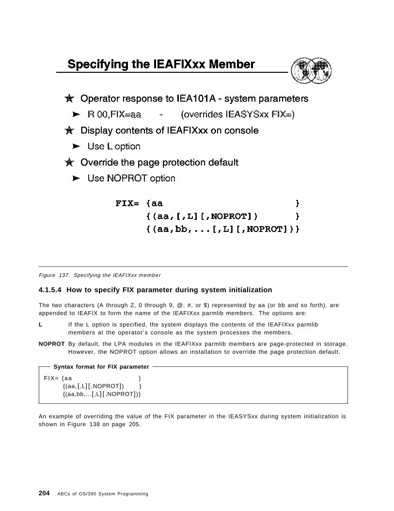
Figure 137. Specifying the IEAFIXxx member
4.1.5.4 How to specify FIX parameter during system initialization
The two characters (A through Z, 0 through 9, @, #, or $) represented by aa (or bb and so forth), areappended to IEAFIX to form the name of the IEAFIXxx parmlib members. The options are:
L If the L option is specified, the system displays the contents of the IEAFIXxx parmlibmembers at the operator′s console as the system processes the members.
NOPROT By default, the LPA modules in the IEAFIXxx parmlib members are page-protected in storage.However, the NOPROT option allows an installation to override the page protection default.
Syntax format for FIX parameter
FIX= {aa }{(aa, [,L] [ ,NOPROT]) }{(aa,bb,... [,L] [ ,NOPROT])}
An example of overriding the value of the FIX parameter in the IEASYSxx during system initialization isshown in Figure 138 on page 205.
204 ABCs of OS/390 System Programming
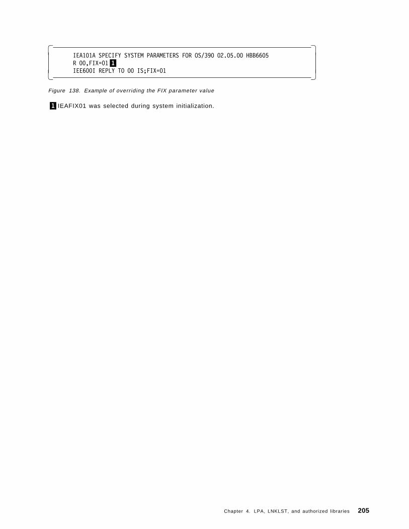
� �IEA101A SPECIFY SYSTEM PARAMETERS FOR OS/390 02.05.00 HBB6605R 00,FIX=01�1�IEE600I REPLY TO 00 IS;FIX=01� �
Figure 138. Example of overriding the FIX parameter value
�1�IEAFIX01 was selected during system initialization.
Chapter 4. LPA, LNKLST, and authorized libraries 205

Figure 139. Modified l ink pack area
4.1.6 Modified link pack area (MLPA/extended MLPA)
This area may be used to contain reenterable routines from APF-authorized libraries that are to bepart of the pageable extension to the link pack area during the current IPL.
The MLPA exists only for the duration of the IPL. Therefore, if an MLPA is desired, the modules in theMLPA must be specified for each IPL (including quick start and warm start IPLs).
4.1.6.1 Contents of the MLPA or extended MLPA
MLPA contains modules listed in the active IEALPAxx member of SYS1.PARMLIB, through thespecification of the MLPA parameter in the IEASYSxx or from the operator′s console at systeminitialization.
LPA modules specified in the IEALPAxx are placed in the MLPA or the extended MLPA, depending onthe RMODE of the modules. Modules with an RMODE of 24 are placed in the MLPA, while those withan RMODE of ANY are placed in the extended MLPA.
206 ABCs of OS/390 System Programming

Figure 140. Coding the IEALPAxx member
4.1.6.2 How to code IEALPAxx of the SYS1.PARMLIB
The visual shows an example of the IEALPAxx member.
The important syntax rules for IEALPAxx are:
• Each statement must begin with the INCLUDE keyword.
• The library name follows the LIBRARY keyword and is enclosed in parentheses.
• The list of modules follows the MODULES keyword and is enclosed in parentheses. Any number ofmodule names can be specified.
• The statement is assumed to be all information from one INCLUDE keyword to the next INCLUDEkeyword or until end-of-file.
Use all columns except 72 through 80.
Chapter 4. LPA, LNKLST, and authorized libraries 207
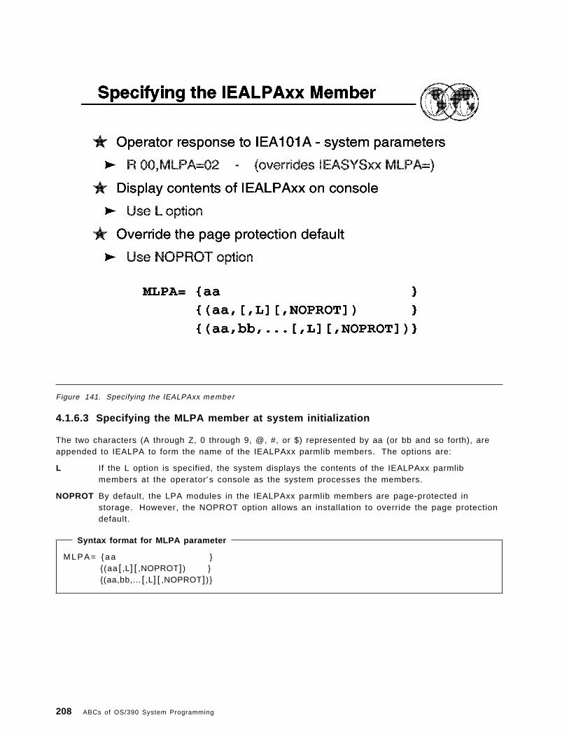
Figure 141. Specifying the IEALPAxx member
4.1.6.3 Specifying the MLPA member at system initialization
The two characters (A through Z, 0 through 9, @, #, or $) represented by aa (or bb and so forth), areappended to IEALPA to form the name of the IEALPAxx parmlib members. The options are:
L If the L option is specified, the system displays the contents of the IEALPAxx parmlibmembers at the operator′s console as the system processes the members.
NOPROT By default, the LPA modules in the IEALPAxx parmlib members are page-protected instorage. However, the NOPROT option allows an installation to override the page protectiondefault.
Syntax format for MLPA parameter
M L P A = { a a }{(aa [,L] [ ,NOPROT]) }{(aa,bb,... [,L] [ ,NOPROT])}
208 ABCs of OS/390 System Programming

An example of overriding the value of the MLPA parameter in the IEASYSxx during system initializationis shown in Figure 142.
� �IEA101A SPECIFY SYSTEM PARAMETERS FOR OS/390 02.05.00 HBB6605R 00,MLPA=02�1�IEE600I REPLY TO 00 IS;MLPA=02� �
Figure 142. Example of overr iding the MLPA parameter value
�1�IEALPA02 was selected during system initialization.
Chapter 4. LPA, LNKLST, and authorized libraries 209
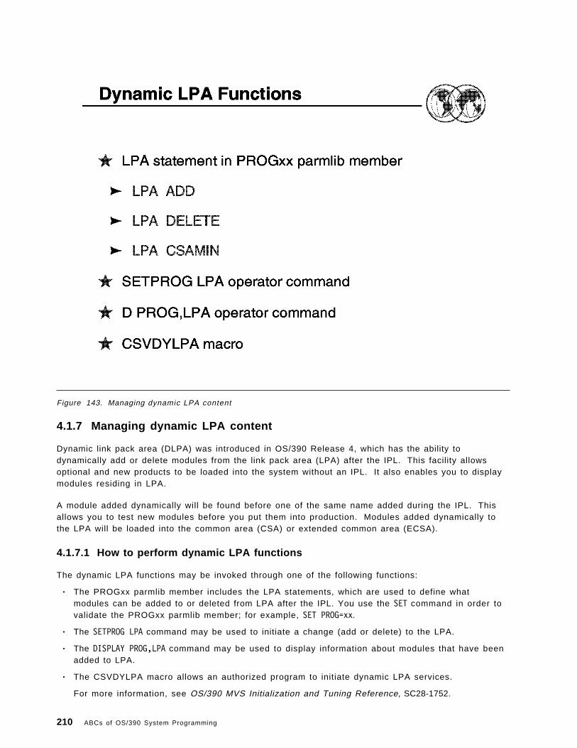
Figure 143. Managing dynamic LPA content
4.1.7 Managing dynamic LPA content
Dynamic link pack area (DLPA) was introduced in OS/390 Release 4, which has the ability todynamically add or delete modules from the link pack area (LPA) after the IPL. This facility allowsoptional and new products to be loaded into the system without an IPL. It also enables you to displaymodules residing in LPA.
A module added dynamically will be found before one of the same name added during the IPL. Thisallows you to test new modules before you put them into production. Modules added dynamically tothe LPA will be loaded into the common area (CSA) or extended common area (ECSA).
4.1.7.1 How to perform dynamic LPA functions
The dynamic LPA functions may be invoked through one of the following functions:
• The PROGxx parmlib member includes the LPA statements, which are used to define whatmodules can be added to or deleted from LPA after the IPL. You use the SET command in order tovalidate the PROGxx parmlib member; for example, SET PROG=xx.
• The SETPROG LPA command may be used to initiate a change (add or delete) to the LPA.
• The DISPLAY PROG,LPA command may be used to display information about modules that have beenadded to LPA.
• The CSVDYLPA macro allows an authorized program to initiate dynamic LPA services.
For more information, see OS/390 MVS Initialization and Tuning Reference, SC28-1752.
210 ABCs of OS/390 System Programming

4.2 The linkList (LNKLST)
This topic explains the LNKLST and the related mechanisms utilized to improve the performance oflocating and fetching modules. It is important to understand the relationship between the LNKLST andLLA/VLF.
When determining which data sets LLA is to manage, try to limit these choices to production loadlibraries that are rarely changed. Because LLA manages LNKLST libraries by default, you need onlydetermine which non-LNKLST libraries LLA is to manage. If, for some reason, you do not want LLA tomanage particular LNKLST libraries, you must explicitly remove such libraries from LLA management.
Because you obtain the most benefit from LLA when you have both LLA and VLF functioning, youshould plan to use both. When used with VLF, LLA reduces the I/O required to fetch modules fromDASD by causing selected modules to be staged in VLF data spaces. LLA does not use VLF tomanage library directories. When used without VLF, LLA eliminates only the I/O the system would usein searching library directories on DASD.
All LLA-managed libraries must be cataloged. This includes LNKLST libraries. A library must remaincataloged for the entire time it is managed by LLA.
The benefits of LLA apply only to modules that are retrieved through the following macros: LINK,LINKX, LOAD, ATTACH, ATTACHX, XCTL, and XCTLX.
LLA does not stage load modules in overlay format. LLA manages the directory entries of overlayformat modules, but the modules themselves are provided through program fetch. If you want to makeoverlay format modules eligible for staging, you must re-linkedit the modules as non-overlay format.These reformatted modules might occupy more storage when they execute and, if LLA does not stagethem, might take longer to be fetched.
Chapter 4. LPA, LNKLST, and authorized libraries 211

Figure 144. The LNKLST
4.2.1 An overview of linkList (LNKLST)
The LNKLST is a group of system and user-defined load libraries, which form part of the search orderthe system uses for programs.
Modules (programs), whether stored as load modules or programs objects, must be loaded into bothvirtual storage and central storage before they can be run.
By default, the LNKLST begins with these system data sets:
• SYS1.LINKLIB
• SYS1.MIGLIB
• SYS1.CSSLIB
You can change this order and add other load libraries to the LNKLST concatenation.
4.2.1.1 The LNKLST concatenation
The LNKLST concatenation is established at IPL time. It consists of SYS1.LINKLIB, followed by thelibraries specified in the LNKLSTxx member(s) of SYS1.PARMLIB. The LNKLSTxx member is selectedthrough the LNK parameter in the IEASYSxx member of the SYS1.PARMLIB. In addition, the systemalso automatically concatenates data sets SYS1.MIGLIB and SYS1.CSSLIB to SYS1.LINKLIB.
The building of the LNKLST concatenation happens during an early stage in the IPL process, before
212 ABCs of OS/390 System Programming

any user catalogs are accessible, so only those data sets whose catalog entries are in the systemmaster catalog may be included in the linklist. However, to include user cataloged data set in theLNKLST concatenation, you have to specify both the name of the data set and the volume serialnumber (VOLSER) of the DASD volume on which the data set resides.
Note: The number of data sets that you can concatenate to form the LNKLST concatenation is limitedby the total number of DASD extents the data sets will occupy. The total number of extents must notexceed 255. When the limit has been exceeded, the system writes error message IEA328E to theoperator ′s console.
These data sets are concatenated in the order in which they appear in the LNKLSTxx member(s), andthe system creates a data extent block (DEB) that describes the data sets concatenated toSYS1.LINKLIB and their extents. This contains details of each physical extent allocated to the linklist.These extents remains in effect for the duration of the IPL. After this processing completes, the librarylookaside (LLA) is started and manages the LNKLST data sets and can be used to control updates tothem.
4.2.1.2 Specifying the LNK parameter
An example of overriding the value of the LNK parameter in the IEASYSxx during system initializationis shown in Figure 145.
� �IEA101A SPECIFY SYSTEM PARAMETERS FOR OS/390 02.05.00 HBB6605R 00,LNK=03�1�IEE600I REPLY TO 00 IS;LNK=03� �
Figure 145. Example of overriding the LNK parameter value
�1�LNKLST03 was selected during system initialization.
For more information, see OS/390 MVS Initialization and Tuning Reference, SC28-1752, and OS/390MVS System Commands, GC28-1781.
Chapter 4. LPA, LNKLST, and authorized libraries 213

Figure 146. Dynamic LNKLST functions
4.2.2 Managing dynamic LNKLST content
You can update the LNKLST content dynamically using the following methods:
• You can create a new PROGxx parmlib member with the new changes to the LNKLST set, thenissue the SET PROG=xx operator command to activate the changes.
• You can simply use the SETPROG LNKLST operator command to update the LNKLST directly.
• You can also use the D PROG,LNKLST command to display information about the LNKLST set.
• Finally, you can use CSVDYNL macro programming service in an authorized program to changethe LNKLST concatenation for associated jobs and address spaces.
For more information, see OS/390 MVS Initialization and Tuning Reference, SC28-1752.
214 ABCs of OS/390 System Programming

Figure 147. Library lookaside
4.2.3 The library lookaside (LLA) overview
Library lookaside (LLA) is an address space that maintain a copy of the directory entries of thelibraries that it manages. Since the entries are cached, the system does not need to read the data setdirectory entries to find out where a module is stored before fetching it from DASD. This greatlyreduces I/O operations.
The main purpose of using LLA is to improve the performance of module fetching on your system.
4.2.3.1 How LLA improves performance
LLA improves the module fetch performance in the following ways:
1. By maintaining (in the LLA address space) copies of the library directories the system uses tolocate load modules. The system can quickly search the LLA copy of a directory in virtual storageinstead of using costly I/O to search the directories on DASD.
2. By placing (or staging) copies of selected modules in a virtual lookaside facility (VLF) data spaceDCSVLLA when you define the LLA class to VLF, and start VLF. The system can quickly fetchmodules from virtual storage, rather than using slower I/O to fetch the modules from the DASD.
3. By determining which modules, if staged, would provide the most benefit to module fetchperformance. LLA evaluates modules as candidates for staging based on statistics it collects aboutthe members of the libraries it manages (such as module size, frequency of fetches per module(fetch count), and the time required to fetch a particular module). If necessary, you can directlyinfluence LLA staging decisions through installation exit routines (CSVLLIX1 and CSVLLIX2).
Chapter 4. LPA, LNKLST, and authorized libraries 215

4.2.3.2 Planning LLA use
Before you can use LLA, you have to do the following:
1. Determine which libraries should be LLA-managed libraries.
2. Code the CSVLLAxx parmlib member to include, modify, and remove the LLA-managed libraries aswell as how to optimize the performance of the search processing and selectively refresh LLAdirectory entries.
3. Learn how to control the LLA through the operator commands Start, Stop, and Modify LLA. LLAdirectory entries may be selectively refreshed via the operator command F LLA,REFRESH.
4.2.3.3 LLA-managed libraries
By default, library lookaside (LLA) address space caches directory entries for all the modules in thedata sets included in the linklist (LNKLST) concatenation (defined in LNKLSTxx or PROGxx parmlibmember).
You can also identify other user-defined load libraries that contain frequently used modules to bemanaged by LLA.
216 ABCs of OS/390 System Programming

Figure 148. Dynamic LNKLST functions
4.2.3.4 CSVLLAxx SYS1.PARMLIB member
You use the CSVLLAxx parmlib member to specify which libraries (in addition to the LNKLSTconcatenation) library lookaside (LLA) is to manage.
Note: If you do not supply a CSVLLAxx member, LLA will by default manage only those librariesdefined in the LNKLST concatenation.
You can also use CSVLLAxx to specify:
• Libraries to be added or removed from LLA management while LLA is active.
• Whether LLA is to hold an enqueue for the libraries it manages.
• Libraries for which LLA is to use the performance-enhancing FREEZE|NOFREEZE option.
• Members of libraries, or whole libraries, to be selectively refreshed in the LLA directory.
• Additional CSVLLAxx members to be used to control LLA processing. These members can residein data sets other than SYS1.PARMLIB.
• Whether exit routines are to be called during LLA processing.
For more information, see OS/390 MVS Initialization and Tuning Reference, SC28-1752.
Chapter 4. LPA, LNKLST, and authorized libraries 217

4.2.3.5 How to start and stop LLA
To start LLA. you use the START LLA,LLA=xx command. This command identifies the CSVLLAxx parmlibmember to build the LLA directory. This command is issued during system initialization by theIBM-supplied IEACMD00 parmlib member; the command can also be entered by the operator.
The parameters for the S LLA command are:
LLA Invokes the LLA procedure and creates the LLA address space.
LLA=xx Indicates which CSVLLAnn parmlib member LLA is to use. If you omit LLA=xx, LLAwill build its directory using only the LNKLST libraries.
SUB=MSTR Indicates that the name of the subsystem that will process the task is the mastersubsystem. If you omit this parameter, the JES subsystem starts LLA. The resultingdependency on JES requires LLA to be stopped when stopping JES.
Note: We recommend that you specify SUB=MSTR on the START LLA command to prevent LLA from failingif JES fails.
Syntax format for S LLA command
S LLA[,SUB=MSTR] [,LLA=xx]
To stop LLA, you use the P LLA operator command.
The parameter for the P LLA command is:
LLA The job name assigned to the LLA address space.
Syntax for P LLA command
P LLA
For more information, see OS/390 MVS Initialization and Tuning Reference, SC28-1752, and OS/390MVS System Commands, GC28-1781.
4.2.3.6 How to modify LLA
You can use the MODIFY LLA command to change LLA dynamically, in one of the following ways:
• MODIFY LLA,REFRESH
This command rebuilds LLA′s directory for the entire set of libraries managed by LLA. This actionis often called the complete refresh of LLA.
• MODIFY LLA,UPDATE=xx
This command rebuilds LLA′s directory only for specified libraries or modules. xx identifies theCSVLLAxx member that contains the names of the libraries for which directory information is to berefreshed. This action is often called a selective refresh of LLA.
218 ABCs of OS/390 System Programming
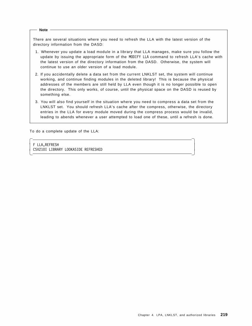
Note
There are several situations where you need to refresh the LLA with the latest version of thedirectory information from the DASD:
1. Whenever you update a load module in a library that LLA manages, make sure you follow theupdate by issuing the appropriate form of the MODIFY LLA command to refresh LLA ′s cache withthe latest version of the directory information from the DASD. Otherwise, the system willcontinue to use an older version of a load module.
2. If you accidentally delete a data set from the current LNKLST set, the system will continueworking, and continue finding modules in the deleted library! This is because the physicaladdresses of the members are still held by LLA even though it is no longer possible to openthe directory. This only works, of course, until the physical space on the DASD is reused bysomething else.
3. You wil l also find yourself in the situation where you need to compress a data set from theLNKLST set. You should refresh LLA′s cache after the compress, otherwise, the directoryentries in the LLA for every module moved during the compress process would be invalid,leading to abends whenever a user attempted to load one of these, until a refresh is done.
To do a complete update of the LLA:
� �F LLA,REFRESHCSV210I LIBRARY LOOKASIDE REFRESHED� �
Chapter 4. LPA, LNKLST, and authorized libraries 219

Figure 149. Compressing LLA-managed libraries
4.2.3.7 How to compress LLA-managed libraries
The procedure for compressing an LLA-managed library is:
1. Create a new CSVLLAxx member that includes a REMOVE statement identifying the library thatneeds to be compressed.
� �Menu Utilities Compilers Help
------------------------------------------------------------------------BROWSE SYS1.PARMLIB(CSVLLA02) - 01.01 Line 00000000 Col 001 080*************************** Top of Data ********************************REMOVE(SYS1.LINKLIB)*************************** Bottom of Data *****************************� �
Then issue the F LLA,UPDATE=xx command:
� �F LLA,UPDATE=02IEE252I MEMBER CSVLLA02 FOUND IN SYS1.PARMLIBCSV210I LIBRARY LOOKASIDE UPDATED� �
2. Compress the library.
There are two ways of compressing a data set:
• You can issue the line command Z against the data set you want to compress from the ISPFpanel.
220 ABCs of OS/390 System Programming

� �Menu Options View Utilities Compilers Help------------------------------------------------------------------------DSLIST - Data Sets Matching SYS1.LINKLIB Row 1 of 1Command ===> Scroll ===> PAGE
Command - Enter ″/″ to select action Message Volume------------------------------------------------------------------------Z SYS1.LINKLIB MPRES1********************* End of Data Set list *****************************� �
• Or you can submit a job to compress the data set using the utility IEBCOPY as shown in thefollowing sample JCL.
� �//COMPRES JOB (),′ MVSSP′ , NOTIFY=&SYSUID,CLASS=A,MSGLEVEL=(1,1),// MSGCLASS=X//*******************************************//* *//* COMPRESSING DATA SETS USING IEBCOPY *//* *//*******************************************//STEP1 EXEC PGM=IEBCOPY//SYSPRINT DD SYSOUT=*//INPUT DD DSNAME=SYS1.LINKLIB,DISP=SHR//OUTPUT DD DSNAME=SYS1.LINKLIB,DISP=SHR//SYSIN DD *
COPY INDD=INPUT,OUTDD=OUTPUT/*� �
3. Create a new CSVLLAxx member that includes a LIBRARIES statement to return the compressedlibrary to LLA management.
� �Menu Utilities Compilers Help
------------------------------------------------------------------------BROWSE SYS1.PARMLIB(CSVLLA03) - 01.01 Line 00000000 Col 001 080*************************** Top of Data ********************************LIBRARIES(SYS1.LINKLIB)*************************** Bottom of Data *****************************� �
Then issue the F LLA,UPDATE=xx command:
� �F LLA,UPDATE=03IEE252I MEMBER CSVLLA03 FOUND IN SYS1.PARMLIBCSV210I LIBRARY LOOKASIDE UPDATED� �
Chapter 4. LPA, LNKLST, and authorized libraries 221

Figure 150. Virtual lookaside facility
4.2.4 Virtual lookaside facility (VLF) overview
The virtual lookaside facility (VLF) is a set of services that can improve the response time ofapplications that must retrieve a set of data for many users. VLF creates and manages data spaces tostore an application′s most frequently used data. When the application makes a request for data, VLFchecks its data space to see if the data is there. If the data is present, VLF can rapidly retrieve itwithout requesting I/O to DASD.
To take advantage of VLF, an application must identify the data it needs to perform its task. The datais known as a data object. Data objects should be small-to-moderate in size, named according to theVLF naming convention discussed later in this section, and associated with an installation-definedclass of data objects.
Certain IBM products or components such as LLA, TSO/E, CAS, and RACF use VLF as an alternate wayto access data. Since VLF uses virtual storage for its data spaces, there are performanceconsiderations that each installation must weigh when planning for the resources required by VLF.
Note: VLF is intended for use with major applications. Because VLF runs as a started task that theoperator can stop or cancel, it cannot take the place of any existing means of accessing data on DASD.Any application that uses VLF must also be able to run without it.
222 ABCs of OS/390 System Programming
4.2.4.1 Using VLF with LLA
You will obtain the most benefit from LLA when you have both LLA and VLF functioning, you shouldplan to use both. When used with VLF, LLA reduces the I/O required to fetch modules from the DASDby causing selected modules to be staged in VLF data spaces.
LLA does not use VLF to manage library directories. When using without VLF, LLA eliminates only theI/O that the system would use in searching for library directories on DASD.
4.2.4.2 VLF considerations
Before you can take full advantage of implementing VLF to improve your system performance, thereare several factors you have to consider; some of these factors are:
• VLF works best with two kinds of data:
− Data objects that are members of partitioned data sets, located through a partitioned data set(PDS) concatenation.
− Data objects that, while not PDS members, could be easily described as a collection of namedobjects that are repeatedly retrieved by many users.
If neither description fits your data objects, it is likely that you would not obtain any performancebenefit from VLF. Remember, there are storage overhead costs associated with using VLF.
• Like data in private storage, data stored through VLF is subject to page stealing. That is, VLFworks best when a significant portion of the data is likely to remain in processor storage and notbe paged out to auxiliary storage.
• VLF works best with relatively small objects because less virtual storage is expended to reduce thenumber of I/O operations.
• VLF is designed to improve performance by increasing the use of virtual storage to reduce thenumber of I/O operations. For a system that is already experiencing a central, expanded, orauxiliary storage constraint, this strategy is probably not a good choice.
4.2.4.3 VLF planning
Before you can use VLF, you have to:
1. Start VLF using the IBM-supplied default COFVLFxx parmlib member.
2. Update COFVLFxx to include the VLF classes associated with the applications or products.
Chapter 4. LPA, LNKLST, and authorized libraries 223

Figure 151. COFVLFxx parmlib member
4.2.5 COFVLFxx parmlib member
You use the COFVLFxx of the SYS1.PARMLIB to define classes of VLF objects. To activate a class ofVLF objects, VLF requires that a CLASS statement describing that group of objects be present in theactive COFVLFxx parmlib member (the member named on the START command used for VLF).
A VLF class is a group of related objects made available to users of an application or component. Toget the most benefit from using VLF, consider its use for objects that are:
• Used frequently
• Changed infrequently
• Used by multiple end users concurrently
Some of the more important statement and parameters for COFVLFxx are:
CLASS Each group of objects that VLF processes must have a CLASS statementdefining it. The CLASS statement indicates that the following parametersdefine that particular group of objects to VLF.
NAME(classname) NAME(classname) specifies the name of the VLF class. The classname maybe 1 to 7 alphanumeric characters including @, #, and $. IBM-supplied VLFclass names begin with the letters A through I, for example, NAME(CSVLLA).
EDSN(dsn) ]VOL(vol) ] For a PDS class, EDSN(dsn) identifies a partitioned data set name whosemembers are eligible to be the source for VLF objects in the class. The dsncan be 1 to 44 alphanumeric characters, including @, #, and periods (.).
224 ABCs of OS/390 System Programming

You do not need to specify the volume if the cataloged data set is the desiredone. If the data set is not cataloged, or if you have multiple data sets with thesame name on different volumes, you must specify VOL(vol). Without thevolume serial number, an uncataloged data is not included in the eligible dataset name list. The system issues an informational message to the operator toidentify any data set where the system cannot find the catalog entry to extractthe volume.
Multiple occurrences of the same data set name with a different volume isacceptable. However if duplicate entries of the same data set name and thesame volume occur, the system issues an informational message and ignoresthe redundant information.
EMAJ(majname) EMAJ identifies an eligible major name (majname) for a non-PDS class, aclass that does not have a major name and minor name related to partitioneddata sets and their members.
The majname can be 1 to 64 alphanumeric characters except comma(,), blank,or right parenthesis ()), for example EMAJ(LLA).
Note: Do not use the EMAJ and the EDSN parameter on the same CLASSstatement.
For more information, see OS/390 MVS Initialization and Tuning Reference, SC28-1752.
Figure 152 shows an example of COFVLFxx:
� �Menu Utilities Compilers Help
------------------------------------------------------------------------BROWSE SYS1.PARMLIB(COFVLF04) - 01.01 Line 00000000 Col 001 080*************************** Top of Data ********************************CLASS NAME(CSVLLA) /* CLASS NAME FOR LIBRARY LOOKASIDE */
EMAJ(LLA) /* MAJOR NAME FOR LIBRARY LOOKASIDE *//* Default MAXVIRT = 4096 4K blocks *//* = 16Mb */
/* */CLASS NAME(IKJEXEC) /* TSO/E VERSION 2 CLIST/REXX INTERFACE */
EDSN(SYS1.OS390.CLIST)EDSN(MVSTOOLS.SHARED.CLIST)MAXVIRT(1024) /* MAXVIRT = 512 4K blocks */
/* = 4Mb *//* */CLASS NAME(IGGCAS) /* MVS/DFP 3.1 CATALOG in Data space */
EMAJ(CATALOG.SC54.MCAT)EMAJ(CATALOG.TOTICF1.VITSO01)MAXVIRT(1024) /* MAXVIRT = 512 4K blocks */
/* = 2Mb (minimum value) */*************************** Bottom of Data *****************************� �
Figure 152. An example of COFVLFxx
4.2.5.1 Starting and stopping VLF
To start VLF, you use the START VLF,SUB=MSTR,N=xx command. This command identifies the COFVLFxxparmlib member to build VLF. This command is issued by the IBM-supplied COMMND00 parmlibmember during system initialization; the command can also be entered by the operator.
The parameters for the S VLF command are:
Chapter 4. LPA, LNKLST, and authorized libraries 225

S VLF,SUB=MSTR[,NN=xx]
Invokes the VLF procedure that starts the virtual lookaside facility (VLF).
NN=xx Indicates that the system is to start VLF using the COFVLFxx member of theSYS1.PARMLIB (default COFVLF00).
Syntax for S VLF command
S VLF,SUB=MSTR[,NN=xx]
To stop VLF, you use the P VLF command.
The parameter for the P VLF command is:
VLF The jobname assigned to the virtual lookaside facility (VLF). Using this parameter stopsVLF with the message COF033I.
Note: Stopping VLF can degrade your system performance.
Syntax for P VLF command
P VLF
226 ABCs of OS/390 System Programming

4.3 The authorized libraries
OS/390 offers a mechanism called the authorized program facility (APF) to restrict the access tosensitive system functions or user programs. APF was designed to avoid integrity exposures. Theinstallation identifies what libraries contain those special functions or programs. Those libraries arethen called APF (authorized program facility) libraries.
The modified link pack area (MLPA) may be used to contain reenterable routines from APF-authorizedlibraries that are to be part of the pageable extension to the link pack area during the current IPL. TheMLPA exists only for the duration of an IPL. Therefore, if an MLPA is desired, the modules in theMLPA must be specified for each IPL (including quick start and warm start IPLs).
The MLPA is allocated just below the FLPA (or the PLPA, if there is no FLPA); the extended MLPA isallocated above the extended FLPA (or the extended PLPA if there is no extended FLPA). When thesystem searches for a routine, the MLPA is searched before the PLPA.
Note: Loading a large number of modules in the MLPA can increase fetch time for modules that arenot loaded in the LPA. This could affect system performance.
The MLPA can be used at IPL time to temporarily modify or update the PLPA with new or replacementmodules. No actual modification is made to the quick start PLPA stored in the system ′s paging datasets. The MLPA is read-only, unless NOPROT is specified on the MLPA system parameter.
Chapter 4. LPA, LNKLST, and authorized libraries 227

Figure 153. The authorized libraries
4.3.1 Authorized libraries overview
Many system functions, such as entire supervisor calls (SVC) or special paths through SVCs, aresensitive. Access to these functions must be restricted to only authorized programs to avoidcompromising the security and integrity of the system.
The system considers a program authorized if the program has one or more of the followingcharacteristics:
• Runs in supervisor state (bit 15 of the PSW is zero).
• Runs with PSW key 0 to 7 (bits 8 through 11 of the PSW are in the range 0 to 7).
• Runs under an APF-authorized job step task
The authorized program facility (APF) allows your installation to identify system or user programs thatcan use sensitive system functions.
Libraries that contain authorized programs are known as authorized libraries. APF-authorizedprograms must reside in one of the following authorized libraries:
• SYS1.LINKLIB
• SYS1.SVCLIB
• SYS1.LPALIB
• An authorized library specified by your installation
228 ABCs of OS/390 System Programming

Note
1. By default, the libraries in the LNKLST concatenation are considered authorized unless youspecified LNKAUTH=APFTAB in the IEASYSxx parameter list. However, if the system accessesthe libraries in the LNKLST concatenation through JOBLIB or STEPLIB DD statements, thesystem does not consider those libraries authorized unless you specified the library name inthe APF list by using either the IEAAPFxx or the PROGxx parmlib member.
2. If a JCL DD statement concatenates an authorized library in any order with an unauthorizedlibrary, the entire set of concatenated libraries is treated as unauthorized.
3. SYS1.LPALIB is treated as an authorized library only while the system builds the pageable linkpack area (PLPA) using the LPALSTxx parmlib member. All modules in PLPA are marked ascoming from an authorized library. When accessed through a STEPLIB, JOBLIB, or TASKLIBDD statement, SYS1.LPALIB is considered an authorized library only if you have included it inthe APF list.
4.3.1.1 Authorized program facility (APF)
You can use the authorized program facility (APF) to identify system or user programs that can usesensitive system functions; for example APF:
• Restricts the use of sensitive system SVC routines (and sensitive user SVC routines, if you needthem) to APF-authorized programs.
• Allows the system to fetch all modules in an authorized job step task only from authorizedlibraries, to prevent programs from counterfeiting a module in the module flow of an authorized jobstep task.
4.3.1.2 Authorizing a program
To authorize a program, you must first assign the authorized code to the first load module of theprogram. APF prevents authorized programs from accessing any load module that is not in anauthorized library. When the system attaches the first load module of a program, the system considersthe program APF-authorized if the module meets both the following criteria:
1. The module is contained in an authorized library.
2. The module is link-edited with authorized code, A C = 1 (to indicate that you want to authorize thejob step task). This code is contained in a bit setting in the partitioned data set (PDS) directoryentry for the module.
4.3.1.3 Link-editing modules with AC=1
You can use the PARM field on the link-edit step to assign the APF-authorization code to a loadmodule. To assign an authorization code using JCL, code AC=1 in the operand field of the PARMparameter of the EXEC statement.
//LKED EXEC PGM=HEWL,PARM=′ AC=1′ , . . .
This method causes the system to consider every load module created by the step to be authorized.
The authorization code of a load module has meaning only when it resides on an APF-authorized dataset and when the load module executes as the first program of a job-step attach. If no authorizationcode is assigned in the linkage editor step, the system assigns the default of authorized. Thus, if aload module tries to execute functions or SVCs that requires authorization, the system abnormallyends the program and issues abend code X′ 306′ reason code X′ 04′ .
Chapter 4. LPA, LNKLST, and authorized libraries 229

4.3.1.4 Guidelines for using APF
When you use APF authorization, you must control which programs are stored in the authorizedlibraries. If the first module in a program sequence is authorized, the system assumes that the flow ofcontrol to all subsequent modules is known and secure as long as these subsequent modules comefrom authorized libraries. To ensure that this assumption is valid you should:
• Ensure that all programs that run as authorized programs adhere to your installation′s integrityguidelines.
• Ensure that no two load modules with the same name exist across the set of authorized libraries.Two modules with the same name could lead to accidental or deliberate mix-up in module flow,possibly introducing an integrity exposure.
• Link edit with the authorization code (AC=1) only the first load module in a program sequence.Do not use the authorization code for subsequent load modules, thus ensuring that a user cannotcall modules out of sequence, or bypass validity checking or critical-logic flow.
It is recommended that you protect the libraries in the APF list with generic security product profiles soonly selected users can store programs in those libraries.
230 ABCs of OS/390 System Programming

Figure 154. How to get APF authorization
4.3.1.5 Specifying program libraries to be APF authorized
The APF list is built during IPL using those libraries specified in the IEAAPFxx or PROGxx parmlibmembers, indicated by the APF and PROG parameters in IEASYSxx, or from the operator′s console atsystem initialization.
Note: You can also dynamically modify the APF list after IPL, but only when you have used thedynamic APF format in the PROGxx.
4.3.1.6 IEAAPFxx parmlib member coding
Use the IEAAPFxx member in the SYS1.PARMLIB to specify program libraries that are to receive APFauthorization. List the data set names of the libraries, along with the volume where the library resides.
To specify the volume where the library resides, use one of the following:
• The volume serial number of the volume on which the library resides.
• Six asterisks (******) to indicate that the library resides on the current SYSRES volume.
• *MCAT* to indicate the library resides on the volume on which the system master catalog resides.
• Nothing after the library name, to indicate that the library is managed by the storage managementsystem (SMS).
Figure 155 on page 232 shows an example of IEAAPFxx.
Chapter 4. LPA, LNKLST, and authorized libraries 231
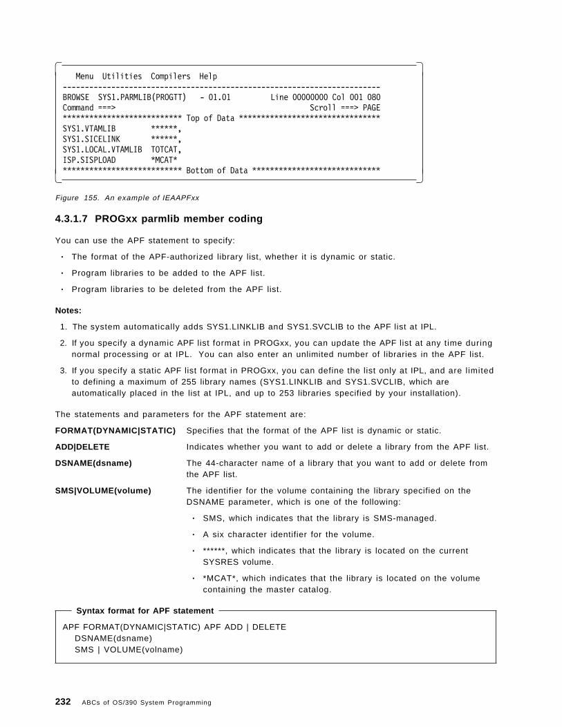
� �Menu Utilities Compilers Help
------------------------------------------------------------------------BROWSE SYS1.PARMLIB(PROGTT) - 01.01 Line 00000000 Col 001 080Command ===> Scroll ===> PAGE*************************** Top of Data ********************************SYS1.VTAMLIB ******,SYS1.SICELINK ******,SYS1.LOCAL.VTAMLIB TOTCAT,ISP.SISPLOAD *MCAT**************************** Bottom of Data *****************************� �
Figure 155. An example of IEAAPFxx
4.3.1.7 PROGxx parmlib member coding
You can use the APF statement to specify:
• The format of the APF-authorized library list, whether it is dynamic or static.
• Program libraries to be added to the APF list.
• Program libraries to be deleted from the APF list.
Notes:
1. The system automatically adds SYS1.LINKLIB and SYS1.SVCLIB to the APF list at IPL.
2. If you specify a dynamic APF list format in PROGxx, you can update the APF list at any time duringnormal processing or at IPL. You can also enter an unlimited number of libraries in the APF list.
3. If you specify a static APF list format in PROGxx, you can define the list only at IPL, and are limitedto defining a maximum of 255 library names (SYS1.LINKLIB and SYS1.SVCLIB, which areautomatically placed in the list at IPL, and up to 253 libraries specified by your installation).
The statements and parameters for the APF statement are:
FORMAT(DYNAMIC|STATIC) Specifies that the format of the APF list is dynamic or static.
ADD|DELETE Indicates whether you want to add or delete a library from the APF list.
DSNAME(dsname) The 44-character name of a library that you want to add or delete fromthe APF list.
SMS|VOLUME(volume) The identifier for the volume containing the library specified on theDSNAME parameter, which is one of the following:
• SMS, which indicates that the library is SMS-managed.
• A six character identifier for the volume.
• ******, which indicates that the library is located on the currentSYSRES volume.
• *MCAT*, which indicates that the library is located on the volumecontaining the master catalog.
Syntax format for APF statement
APF FORMAT(DYNAMIC|STATIC) APF ADD | DELETEDSNAME(dsname)SMS | VOLUME(volname)
232 ABCs of OS/390 System Programming

Figure 156 on page 233 shows an example of PROGxx.
� �Menu Utilities Compilers Help
------------------------------------------------------------------------BROWSE SYS1.PARMLIB(PROGTT) - 01.01 Line 00000000 Col 001 080Command ===> Scroll ===> PAGE*************************** Top of Data ********************************APF FORMAT(DYNAMIC)APF ADD
DSNAME(SYS1.VTAMLIB)VOLUME(******)
APF ADDDSNAME(SYS1.SICELINK)VOLUME(******)
APF ADDDSNAME(SYS1.LOCAL.VTAMLIB)VOLUME(TOTCAT)
APF ADDDSNAME(ISP.SISPLOAD)VOLUME(*MCAT*)
*************************** Bottom of Data *****************************� �Figure 156. Example of PROGxx
Note
It is recommended that you use the PROGxx instead of IEAAPFxx parmlib member to define theAPF list, regardless of whether you plan to take advantage of the dynamic update capability.
If you specify both the PROG=xx and the APF=xx parameters, the system places into the APF listthose libraries listed in the IEAAFPxx, followed by those libraries in the PROGxx.
If you are currently using the IEAAPFxx parmlib member to define the APF list, you can convert theformat of IEAAPFxx to a PROGxx format using an IEAAPFPR REXX exec provided by IBM.
For more information, see OS/390 MVS Initialization and Tuning Reference, SC28-1752.
Chapter 4. LPA, LNKLST, and authorized libraries 233

Dynamic APF functions
Figure 157. Dynamic APF functions
4.3.2 Managing dynamic APF
You can use the following ways to update the content of the APF table dynamically:
• Use PROGxx parmlib member which includes the appropriate APF statement to define the change.
• The SETPROG AFP operator can also initiate a change to the APF table.
• The DISPLAY AFP command may be used to display the list of libraries authorized by APF.
4.3.2.1 Using the PROGxx parmlib member
As mentioned in the previous section, you can use the APF statement to add or delete libraries fromthe APF list.
To delete a library from the APF list use the following command:
Example of the APF DELETE
APF DELETEDSNAME(SCRIPT.R40.DCFLOAD)VOLUME(MPRES2)
Activate the change by using a SET PROG=xx command as shown in Figure 158 on page 235.
234 ABCs of OS/390 System Programming

� �SET PROG=T4IEE252I MEMBER PROGT4 FOUND IN SYS1.PARMLIBCSV410I DATA SET SCRIPT.R40.DCFLOAD ON VOLUME MPRES2 DELETED FROM APFLISTIEE536I PROG VALUE T4 NOW IN EFFECT� �
Figure 158. Example of SET PROGxx command to activate an APF list change
To add a library to the APF list use the following command:
Example of the APF ADD
APF ADDDSNAME(MYPROG.LOADLIB)VOLUME(MPRES3)
Activate the change by using a SET PROG=xx command as shown in Figure 159.
� �SET PROG=T5IEE252I MEMBER PROGT5 FOUND IN SYS1.PARMLIBCSV410I DATA SET MYPROG.LOADLIB ON VOLUME MPRES2 ADDED TO APF LISTIEE536I PROG VALUE T5 NOW IN EFFECT� �
Figure 159. Activating a change to add an APF library
4.3.2.2 Using the SETPROG APF command
Use the SETPROG APF operator command to perform the following functions:
• Change the format of the authorized program facility (APF) list from static to dynamic, or static todynamic.
• Add a library to a dynamic APF list.
• Delete a library from a dynamic APF list.
Syntax format for SETPROG APF command
SETPROG APF{,FORMAT={DYNAMIC|STATIC}}{,{ADD|DELETE},DSNAME|LIBRARY=libname,{SMS|VOLUME=volume}}
To change the format of the APF list to dynamic:
� �SETPROG APF,FORMAT=DYNAMICCSV410I APF FORMAT IS NOW DYNAMIC� �
To add a library to the APF list:
� �SETPROG APF,ADD,DSNAME=SCRIPT.R40.DCFLOAD,VOLUME=MPRES2CSV410I DATA SET SCRIPT.R40.DCFLOAD ON VOLUME MPRES2 ADDED TO APF LIST� �
To delete a library from the APF list:
Chapter 4. LPA, LNKLST, and authorized libraries 235

� �SETPROG APF,DELETE,DSNAME=SCRIPT.R40.DCFLOAD,VOLUME=MPRES2CSV410I DATA SET SCRIPT.R40.DCFLOAD ON VOLUME MPRES2 DELETED FROM APF� �
Note: If you try to add or delete from a APF list that is in a static format, the system responds with aCSV411I message.
� �SETPROG APF,DELETE,DSNAME=SCRIPT.R40.DCFLOAD,VOLUME=MPRES2CSV411I ADD/DELETE IS NOT ALLOWED BECAUSE APF FORMAT IS STATIC� �
4.3.2.3 Using the DISPLAY APF command
You can use the DISPLAY APF command to display or more entries in the list of APF-authorized libraries.Each entry in the APF list display contains:
• An entry number.
• The name of an authorized library.
• An identifier for the volume on which the authorized library resides (or *SMS*, if the library isSMS-managed).
Syntax for DISPLAY APF command
D PROG,APF[,ALL ]| ,DSNAME=l ibname|,ENTRY=xxx|,ENTRY=(xxx-yyy)
],L={a|cc|cca|name|name-a} ]
To display all the whole APF list:
� �D PROG,APFCSV450I 05.18.16 PROG,APF DISPLAY 971FORMAT=DYNAMICENTRY VOLUME DSNAME
1 MPRES1 SYS1.LINKLIB2 MPRES1 SYS1.SVCLIB3 MPRES1 CPAC.LINKLIB�1� .
.
. 36 MPRES2 NETVIEW.V2R4M0.USERLNK 37 MPRES2 NPM.V2R3M0.SFNMLMD1 38 MPRES2 EMS.V2R1M0.SEMSLMD0� �
�1�This is the decimal entry number for each of the libraries defined in the APF list.
To display the specific library at entry number 1:
236 ABCs of OS/390 System Programming

� �D PROG,APF,ENTRY=1CSV450I 05.24.55 PROG,APF DISPLAY 979FORMAT=DYNAMICENTRY VOLUME DSNAME
1 MPRES1 SYS1.LINKLIB� �
To display the all the libraries in the range from 1 to 5:
� �D PROG,APF,ENTRY=(1-5)CSV450I 05.26.27 PROG,APF DISPLAY 981FORMAT=DYNAMICENTRY VOLUME DSNAME
1 MPRES1 SYS1.LINKLIB2 MPRES1 SYS1.SVCLIB3 MPRES1 CPAC.LINKLIB4 MPRES1 ISF.SISFLOAD5 MPRES1 ISF.SISFLPA� �
Chapter 4. LPA, LNKLST, and authorized libraries 237

238 ABCs of OS/390 System Programming

Chapter 5. Catalogs
A catalog describes data set attributes and records the location of a data set so that the data set canbe retrieved without requiring the user to specify the data set′s location. Multiple user catalogscontain information about user data sets, and a single master catalog contains entries for system datasets and user catalogs.
In OS/390 the component controlling catalogs, also called Catalog Manager, is embedded inDFSMSdfp, which supports three types of catalogs, which can coexist on the same operating system:
• ICF catalogs
• VSAM catalogs
• CVOLs
All data sets managed by the storage management subsystem (SMS) must be cataloged in a ICFcatalog.
Most installations depend on the availability of catalog facilities to run production job streams and tosupport online users. For maximum reliability and efficiency, all permanent data sets should becataloged and all catalogs should be integrated catalog facility catalogs. See DFSMS/MVS Version 1Release 4 Managing Catalogs, SC26-4914, for information on VSAM catalogs and CVOLS and how toconvert to integrated catalogs.
Copyright IBM Corp. 2000 239

Figure 160. Catalogs
5.1 Catalogs
A catalog is a data set which contains information about other data sets. It provides users with theability to locate a data set by name, without knowing where the data set resides. By cataloging datasets, your users need to know less about your storage setup. Thus, data sets can be moved from onedevice to another, without requiring a change in JCL DD statements which refer to an existing data set.
Cataloging data sets also simplifies backup and recovery procedures. Catalogs are the centralinformation point for VSAM data sets; all VSAM data sets must be cataloged. In addition, allSMS-managed data sets must be cataloged.
DFSMS/MVS provides three types of catalogs: integrated catalog facility catalogs (ICV), VSAMcatalogs, and operating system control volumes (OS CVOLs).
The integrated catalog facility should satisfy all your cataloging needs. Any type of data set or objectcan be cataloged in an integrated catalog facility catalog. Functions provided for VSAM catalogs andOS CVOLs are for compatibility only. Many advanced MVS/DFP functions require the use of integratedcatalog facility catalogs (for example, the storage management subsystem).
This chapter will provide information only about ICF Catalogs, for further information about VSAMCatalogs and OS CVOLs catalogs, refer to DFSMS/MVS Version 1 Release 4: Managing Catalogs,SC26-4914.
240 ABCs of OS/390 System Programming

Figure 161. Introduction to ICF
5.2 Introduction to ICFAn integrated catalog facility has two components, a VSAM volume data set (VVDS) and a basiccatalog structure (BCS), the following topics explain these components in more detail.
5.2.1 Basic catalog structure (BCS)
The basic catalog structure is a VSAM key-sequenced data set. It uses the data set name as a key tostore and retrieve data set information. For VSAM data sets, the BCS contains volume, security,ownership, and association information. For non-VSAM data sets, the BCS contains volume ownership,and association information. In other words the BCS portion of the ICF catalogs contains the staticinformation about the data set, the information that changes very seldom.
For non-VSAM data sets that are not SMS-managed all their catalog information is only contained inthe BCS. For the other types of data sets, there is other information available in the VVDS.
Related information in the BCS is grouped into logical, variable-length, spanned records related bykey. The BCS uses keys that are the data set names (plus one character for extensions). A controlinterval can contain multiple BCS records. To reduce the number of I/Os necessary for catalogprocessing, logically-related data is consolidated in the BCS.
Chapter 5. Catalogs 241

5.2.2 VSAM volume data set (VVDS)
The VVDS is a VSAM entry-sequenced data set (ESDS) that has a 4 KB control interval size. Itcontains additional catalog information (not contained in the BCS) about the VSAM and SMS-managednon-VSAM data sets residing on the volume where the VVDS is located. Every volume containing anyVSAM or any SMS-managed data sets must have a VVDS in it. In a sense, we may say that the VVDSis a sort for VTOC extension for certain type of data sets. A VVDS may have data set informationabout data sets cataloged in distinct BCSs.
VVDs contains the data set characteristics, extent information, and the volume-related information ofthe VSAM data sets cataloged in the BCS. If you are using the storage management subsystem (SMS),the VVDS also contains data set characteristics and volume-related information for the non-VSAM,SMS-managed data sets on the volume. As you can see the type of information retained in VVDS ismore frequently modified or more volatile than the one in BCS.
A VVDS is recognized by the restricted data set name SYS1.VVDS.Vvolser, where volser is the volumeserial number of the volume on which the VVDS resides.
You can explicitly (via IDCAMS) define the VVDS, or it is implicitly created after you define the firstVSAM data set in the volume or the first non-VSAM SMS-managed data set.
An explicitly defined VVDS is not related to any BCS until a data set or VSAM object is defined on thevolume. As data sets are allocated on the VVDS volume, each BCS with VSAM or SMS-managed datasets residing on that volume is related to the VVDS. An explicit definition of a VVDS does not updateany BCS and, therefore, can be performed before the first BCS in the installation is defined. Explicitlydefining a VVDS is usually appropriate when you are initializing a new volume. If you are not runningSMS, and a volume already contains some non-VSAM data sets, it is appropriate to allow the VVDS tobe defined implicitly with the default space allocation of TRACKS(10 10).
The VVDS is composed of a minimum of two records:
• A VSAM volume control record (VVCR)
• A VVDS self-describing volume record
The first logical record in a VVDS is the VSAM volume control record (VVCR). It contains informationfor management of DASD space and the BCS names which currently have cataloged VSAM orSMS-managed non-VSAM data sets on the volume. It might have a pointer to an overflow VVCR.
The second logical record in the VVDS is the VVDS self-describing VVR (VSAM volume record). Thisself-describing VVR contains information that describes the VVDS.
The remaining logical records in the VVDS are VVRs for VSAM objects or non-VSAM volume records(NVRs) for SMS-managed non-VSAM data sets. The hexadecimal RBA of the record is used as its keyor identifier.
5.2.3 VSAM volume records (VVR)
VSAM volume records contain information about the VSAM data sets residing on the volume with theVVDS. The number of VVRs for VSAM data sets varies according to the type of data set and theoptions specified for the data set.
5.2.4 Non-VSAM volume record (NVR)
The non-VSAM volume record (NVR) is equivalent to a VVR record, but the NVR record is forSMS-managed non-VSAM data sets. The NVR contains SMS-related information.
242 ABCs of OS/390 System Programming

Figure 162. Master catalog
5.3 Catalogs by function
By function the catalogs can be classified as Mastercat (master catalog) and Usercats (user catalogs).A particular case of Usercat is the Volcat, that is a Usercat containing only tape library and tapevolume entries.
There is no structural difference between a Mastercat and a Usercat. What makes a Mastercatdifferent is how it is used, and what data sets are cataloged in it.
5.3.1 Master catalog
Each system has one active Mastercat. The Mastercat does not have to reside on the systemresidence volume. For performance, recovery, and reliability, we recommend that you only useintegrated catalog facility catalogs. Also, a Mastercat can be shared between different MVS images.
The Mastercat for a system must contain entries for all Usercats (and their aliases), which the systemuses. The only other data sets which you should catalog in the Mastercat are the system, or SYS1data sets. These data sets must be cataloged in the Mastercat for proper system initialization.
Chapter 5. Catalogs 243

5.3.2 The Mastercat at system initialization
During a system initialization, the Mastercat is read so that system data sets and Usercats can belocated. Their catalog entries are placed in the in-storage catalog cache as they are read.
Catalog aliases are also read during system initialization, but they are placed in an alias tableseparate from the in-storage catalog. The concept of aliases is covered in 5.3.4.1, “Using aliases” onpage 246.
Thus, if the Mastercat only contains entries for system data sets, catalogs, and catalog aliases, theentire Mastercat is in main storage by the completion of the system initialization.
5.3.2.1 Identifying the Mastercat
At IPL, you must indicate the location (Volser and data set name) of the Mastercat, this can be doneby:
• SYSCATxx member of SYS1.NUCLEUS data set or the default member name that is SYSCATLG(also in SYS1.NUCLEUS).
• LOADxx member of SYS1.PARMLIB / SYS1.IPLPARM. We recomend this method.
244 ABCs of OS/390 System Programming

Figure 163. Identifying the Mastercat
5.3.3 Identifying the Mastercat
The LISTCAT command lists each catalog entry with the generic name GENERIC.*.BAKER, where * isany 1- to 8-character simple name. The parameters are:
ENTRIES Specifies the entryname of the object to be listed. Because GENERIC.*.BAKER is a genericname, more than one entry can be listed
An easy way to identify the Mastercat (after definition) is via ISPF 3.4. Type SYS1.PARMLIB and whenthe SYS1.PARMLIB data sets are listed, enter beside the SYS1.PARMLIB name type LISTC ENT(/), asshown in this visual.
Note: The �/� specifies to use the data set name on the line where the command is entered.
The response to the command is shown at the bottom of the visual as follows:
NONVSAM ------- SYS1.PARMLIBIN-CAT --- MCAT.OS3R5V01.VTOTCAT
Chapter 5. Catalogs 245

Figure 164. Using aliases
5.3.4 Usercats
An ICF Usercat has the same structure as an ICF Mastercat. The difference is in the Usercat function.Mastercat should be used to contain information about system data sets (SYS1.) and pointers toUsercats. Usercats should be used to contain information about your installation cataloged data sets,this is implemented through the alias concept.
5.3.4.1 Using aliases
The way to tell catalog management in which Usercat your data set is cataloged is through aliases.You define an appropriate alias name for an Usercat in the Mastercat. Next, you match thehighest-level qualifier (HLQ) of your data set with the alias. This, identifies the appropriate Usercat tobe used to satisfy the request.
In this visual all data sets with an HLQ of PAY, have their information in the Usercat UCAT1, becausein the Mastercat there is an alias PAY pointing to UCAT1. The ones with DEPT1 and DEPT2 have theirinformation in the Usercat UCAT2, because in the Mastercat there are aliases DEPT1 and DEPT2pointing to UCAT2.
Note that aliases can also be used with non-VSAM data sets in order to create alternate names to thesame data set.
246 ABCs of OS/390 System Programming

Figure 165. The catalog search order
5.3.5 Catalog search order
Most catalog searches should be based on catalog aliases. Some alternatives to catalog aliases areavailable for directing a catalog request, specifically the JOBCAT and STEPCAT DD statements, theCATALOG parameter of access method services, and the name of the catalog.
5.3.5.1 Search order for catalogs
For the system to determine where a data set is to be cataloged, the following search order is used tofind the catalog:
1. If the IDCAMS Define (creation and cataloging) statement is used and the CATALOG parameter(directs the search to an specific catalog) is indicated, then use this referred catalog
2. Otherwise, use the catalog named in the STEPCAT DD statement
3. If no STEPCAT, use the catalog named in the JOBCAT DD statement
4. If no JOBCAT, and the HLQ is a catalog alias, use the catalog identified by the alias or the catalogwhose name is the same as the same HLQ of the data set
5. If no catalog has been identified yet, use the Mastercat.
Chapter 5. Catalogs 247
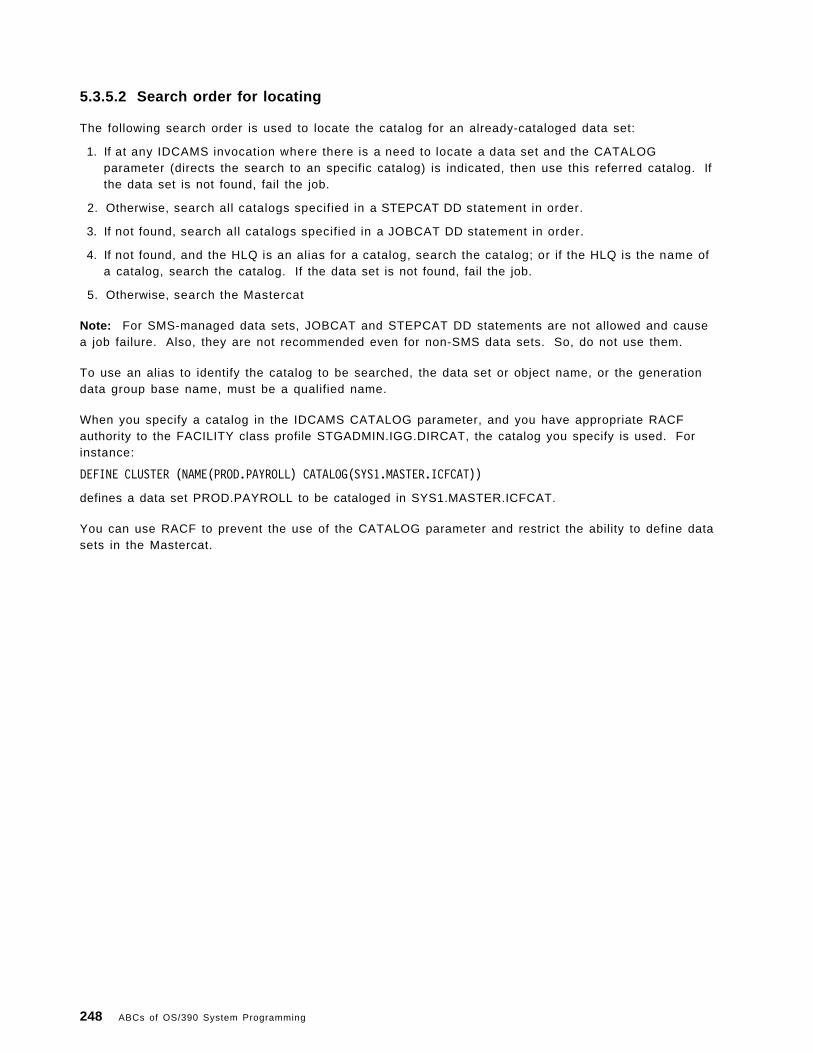
5.3.5.2 Search order for locating
The following search order is used to locate the catalog for an already-cataloged data set:
1. If at any IDCAMS invocation where there is a need to locate a data set and the CATALOGparameter (directs the search to an specific catalog) is indicated, then use this referred catalog. Ifthe data set is not found, fail the job.
2. Otherwise, search all catalogs specified in a STEPCAT DD statement in order.
3. If not found, search all catalogs specified in a JOBCAT DD statement in order.
4. If not found, and the HLQ is an alias for a catalog, search the catalog; or if the HLQ is the name ofa catalog, search the catalog. If the data set is not found, fail the job.
5. Otherwise, search the Mastercat
Note: For SMS-managed data sets, JOBCAT and STEPCAT DD statements are not allowed and causea job failure. Also, they are not recommended even for non-SMS data sets. So, do not use them.
To use an alias to identify the catalog to be searched, the data set or object name, or the generationdata group base name, must be a qualified name.
When you specify a catalog in the IDCAMS CATALOG parameter, and you have appropriate RACFauthority to the FACILITY class profile STGADMIN.IGG.DIRCAT, the catalog you specify is used. Forinstance:
DEFINE CLUSTER (NAME(PROD.PAYROLL) CATALOG(SYS1.MASTER.ICFCAT))
defines a data set PROD.PAYROLL to be cataloged in SYS1.MASTER.ICFCAT.
You can use RACF to prevent the use of the CATALOG parameter and restrict the ability to define datasets in the Mastercat.
248 ABCs of OS/390 System Programming

Figure 166. Access method service
5.4 Access method service (AMS)
You use access method services to define and maintain catalogs. Access method services commandscan also be used to define and maintain VSAM and non-VSAM data sets. For a complete explanationof the usage of access method services, the required JCL, and examples, see DFSMS/MVS Version 1Release 4: Access Method Services for Integrated Catalog Facility, SC26-4906.
Table 4 lists some Access Method Service commands that can be used with catalogs.
Table 4 (Page 1 of 2). Some AMS commands that can be used with catalogs
Command Explanation
ALTER(1) Alters previously defined catalog entries or certain catalog attributes,including entries for tape volume catalogs.
CNVTCAT Converts entries in an OS CVOL or VSAM catalog into integratedcatalog facility catalog entries.
CREATE(1) Creates tape library or tape volume entries.
DEFINE Defines catalog entries.
DEFINE CLUSTER Defines VVDSs and catalog entries.
DEFINE USERCATALOG Defines user catalogs including tape volume catalogs (DEFINEUSERCATALOG VOLCATALOG).
Chapter 5. Catalogs 249

Table 4 (Page 2 of 2). Some AMS commands that can be used with catalogs
Command Explanation
DELETE(1) Deletes catalog and VVDS entries, data sets, catalogs, VVDSs, and dataset control blocks in the VTOC.
DIAGNOSE(2) Determines whether the content of BCS or VVDS records is invalid orunsynchronized.
EXAMINE Determines whether structural errors exist in the index or datacomponent of a BCS.
EXPORT Creates a backup copy of a catalog or copy that can be moved toanother system or volume.
EXPORT DISCONNECT Disconnects the catalog from the Mastercat.
IMPORT Restores an exported backup copy of a catalog, or makes a catalog thatwas previously exported from one system, available for use in anothersystem.
IMPORT CONNECT Connects the catalog to the Mastercat on the same system, or on anyshared system.
LISTCAT Lists catalog entries including entries for tape volume catalogs.
PRINT Prints data set or catalog records.
REPRO Copies catalogs; splits catalog entries between two catalogs; mergescatalog entries into another user catalog or Mastercat. REPROsupports tape volume catalogs.
VERIFY Causes a catalog to reflect the end of a data set correctly after an errorthat prevented closing a VSAM data set. The error might cause thecatalog to be incorrect.
Notes:
1. The access method services ALTER, CREATE, and DELETE commands should only be used to recoverfrom tape volume catalog errors. since access method services cannot change the librarymanager inventory in an automated tape library, ISMF should be used for normal tape libraryALTER, CREATE, and DELETE functions.
2. DIAGNOSE recognizes tape library and tape volume record types. It checks the cell structure of thevolume catalog.
250 ABCs of OS/390 System Programming

Figure 167. Creating a basic catalog structure
5.5 Creating a basic catalog structure (BCS)
Use the access method services DEFINE USERCATALOG ICFCATALOG command to define the basic catalogstructure of an ICF catalog. This visual shows an example of using this command.
Use the access method services DEFINE USERCATALOG VOLCATALOG to define a catalog that only containstape library and tape volume entries. See DFSMS/MVS Version 1 Release 4: Access Method Servicesfor Integrated Catalog Facility, SC26-4906, for more detail.
Chapter 5. Catalogs 251

Figure 168. Defining a BCS with model
5.5.1 Defining a BCS with model
When you define a BCS or VVDS, you can use an existing BCS or VVDS as a model for the new one.The attributes of the existing data set are copied to the newly defined data set, unless you explicitlyspecify a different value for an attribute. You can override any of a model ′s attributes.
If you do not want to change or add any attributes, you need only supply the entry name of the objectbeing defined and the MODEL parameter. When you define a BCS, you must also specify the volumeand space information for the BCS.
In this visual there is one example of that; where:
• NAME specifies the name of the catalog to be defined as RSTUCAT2.
• VOLUME specifies that the catalog is to reside on volume VSER03. Volume VSER03 is dynamicallyallocated.
• MODEL identifies USERCAT4 as the catalog to use as a model for RSTUCAT2. The attributes andspecifications of USERCAT4 that are not otherwise specified with the shown parameters are usedto define the attributes and specifications of RSTUCAT2. The master catalog, AMAST1, contains auser-catalog connector entry that points to USERCAT4. This is why USERCAT4 is specified asMODEL′s catname subparameter. Values and attributes that apply to RSTUCAT2 as a result ofusing USERCAT4 as a model are:
− FOR = 365 days (retention period)
− CYLINDERS = 3 (primary) and 2 (secondary) are allocated to the catalog
252 ABCs of OS/390 System Programming

− BUFFERSPACE = 3072 bytes
− ATTEMPTS = 2
− NOWRITECHECK
− CODE is null
− AUTHORIZATION is null
− OWNER is null
Because catalogs contain their own entries, you must specify the name of the catalog twice in theMODEL parameter.
Chapter 5. Catalogs 253

Figure 169. Defining aliases
5.5.2 Defining aliases
To use a catalog, the system must be able to determine which data sets should be defined in thatcatalog. The simplest way to accomplish this is to define aliases in Mastercat for the catalog—if it is aUsercat. Before defining an alias, carefully consider the effect the new alias has on old data sets. Apoorly chosen alias could make some data sets inaccessible.
You can define aliases for the Usercat in the same job in which you define the catalog by includingDEFINE ALIAS commands after the DEFINE USERCATALOG COMMAND. You can use conditional operators toensure the aliases are only defined if the catalog is successfully defined. After the catalog is defined,you can add new aliases or delete old aliases.
Catalog aliases are defined only in the Mastercat, which contains an entry for the user catalog. Thenumber of aliases a catalog can have is limited by the maximum record size for the Mastercat. If theMastercat is defined with the default record sizes, there is a practical maximum of 3000 aliases percatalog, assuming the aliases are only for HLQs. If you use multilevel aliases, fewer aliases percatalog can be defined.
You cannot define an alias if a data set cataloged in the Mastercat has the same high-level qualifier asthe alias. The DEFINE ALIAS command fails with a duplicate data set name error. For example, if acatalog is named TESTE.TESTSYS.ICFCAT, you cannot define the alias TESTE for any catalog.
This visual shows a DEFINE ALIAS job.
254 ABCs of OS/390 System Programming
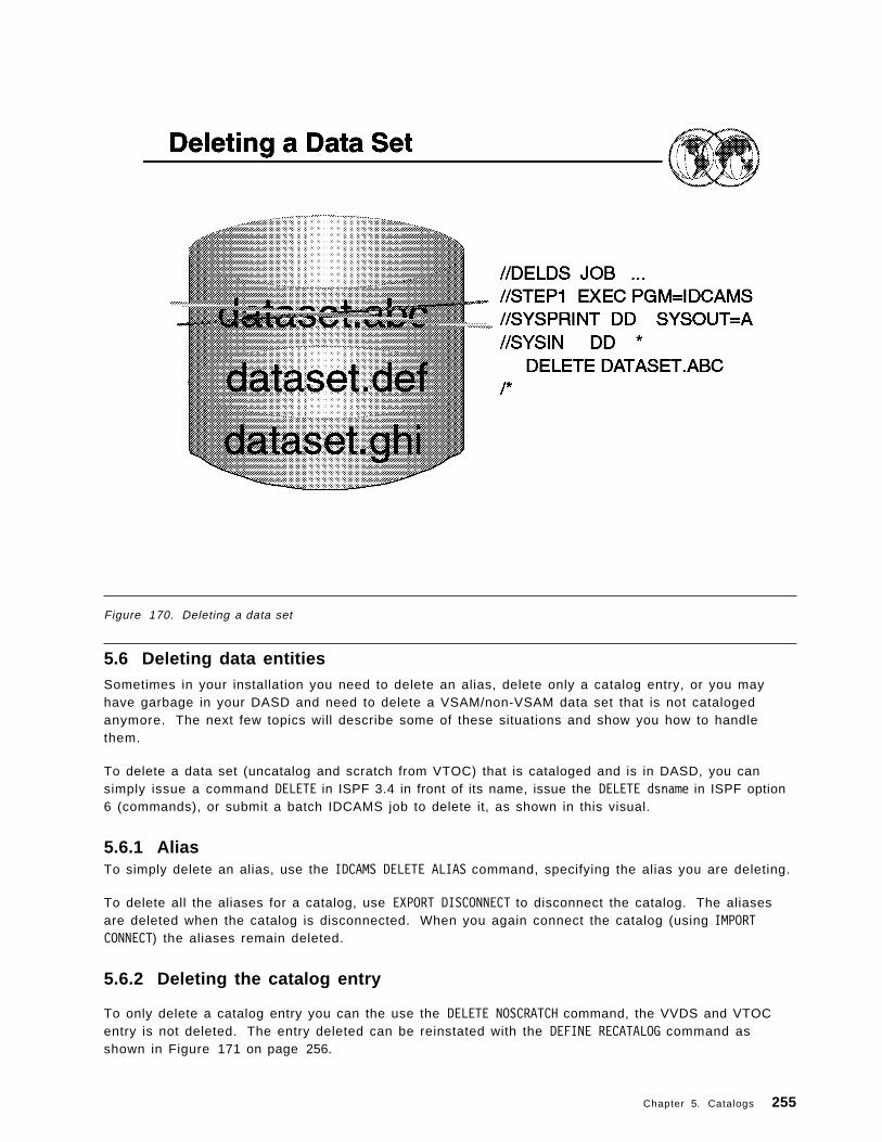
Figure 170. Deleting a data set
5.6 Deleting data entitiesSometimes in your installation you need to delete an alias, delete only a catalog entry, or you mayhave garbage in your DASD and need to delete a VSAM/non-VSAM data set that is not catalogedanymore. The next few topics will describe some of these situations and show you how to handlethem.
To delete a data set (uncatalog and scratch from VTOC) that is cataloged and is in DASD, you cansimply issue a command DELETE in ISPF 3.4 in front of its name, issue the DELETE dsname in ISPF option6 (commands), or submit a batch IDCAMS job to delete it, as shown in this visual.
5.6.1 AliasTo simply delete an alias, use the IDCAMS DELETE ALIAS command, specifying the alias you are deleting.
To delete all the aliases for a catalog, use EXPORT DISCONNECT to disconnect the catalog. The aliasesare deleted when the catalog is disconnected. When you again connect the catalog (using IMPORTCONNECT) the aliases remain deleted.
5.6.2 Deleting the catalog entry
To only delete a catalog entry you can the use the DELETE NOSCRATCH command, the VVDS and VTOCentry is not deleted. The entry deleted can be reinstated with the DEFINE RECATALOG command asshown in Figure 171 on page 256.
Chapter 5. Catalogs 255

� �//DELNOSCR JOB ...//STEP1 EXEC PGM=IDCAMS//SYSPRINT DD SYSOUT=A//SYSIN DD *
DELETE VERA.DATASET NOSCR/*� �
Figure 171. Example DEFINE RECATALOG command
5.6.3 VVR and NVR records
When the catalog entry is missing, and the data set remain in the DASD you can use the DELETE VVR forVSAM data sets and DELETE NVR for non-VSAM SMS-managed data sets as shown in Figure 172.
� �//DELGDG JOB ...
//STEP1 EXEC PGM=IDCAMS //DD1 UNIT=3390,VOL=SER=FERNAN
//SYSPRINT DD SYSOUT=ADELETE -VERA.LUZ.VSAM.INDEX -FILDE(DD1) -VVR� �
Figure 172. Example DELETE VVR command
Caution
When deleting VSAM KSDS, you must issue a DELETE VVR for each of the components, the DATA,and the INDEX.
5.6.4 Generation data group (GDG)
In this example, a generation data group base catalog entry, GDGBASE is deleted from the catalog.The generation data sets associated with GDGBASE remain unaffected in the VTOC, as shown in theJCL shown in Figure 173.
� �//DELGDG JOB ...//STEP1 EXEC PGM=IDCAMS//SYSPRINT DD SYSOUT=A
DELETE -GDGBASE -GENERATIONDATAGROUP -RECOVERY
/*� �Figure 173. Example of deleting a GDB catalog entry
The DELETE command removes the GDG base catalog entry from the catalog. Its parameters are:
GDGBASE GDGBASE is the name of the GDG base entry.
256 ABCs of OS/390 System Programming

GENERATIONDATAGROUP GENERATIONDATAGROUP specifies the type of entry being deleted.VSAM verifies that GDGBSE is a GDG entry, then deletes it. If GDGBASEis not a GDG entry, VSAM issues a message and does not delete it.
RECOVERY RECOVERY specifies that only the GDG base entry name in the catalog bedeleted. Its associated generation data sets remain intact in the VTOC.
5.6.5 Delete an ICF
When deleting an ICF, you must take care if you want to delete only the catalog, or if you want todelete all associated data. The following examples show how to delete a catalog.
5.6.5.1 Delete with recovery
In this example, a user catalog is deleted in preparation for replacing with an imported backup copy.The VVDS and VTOC entries for objects defined in the catalog are not deleted and the data sets arenot scratched, as shown in Figure 174.
� �//DELICF JOB ...//STEP1 EXEC PGM=IDCAMS//DD1 DD VOL=SER=CACSW3,UNIT=3380,DISP=OLD//SYSPRINT DD SYSOUT=A//SYSIN DD *
DELETE -USERCAT -FILE(DD1) -RECOVERY -USERCATALOG
/*� �Figure 174. Example of deleting and replacing a user catalog
RECOVERY
Specifies that only the catalog data set is deleted without deleting the objects defined in thecatalog.
5.6.5.2 Delete an empty user catalog
In the example shown in Figure 175, a user catalog is deleted. A user catalog can be deleted when itis empty—that is, when there are no objects cataloged in it other than the catalog′s volume. If thecatalog is not empty, it cannot be deleted unless the FORCE parameter is specified.
� �//DELICF JOB ...//STEP1 EXEC PGM=IDCAMS//SYSPRINT DD SYSOUT=A//SYSIN DD *
DELETE -CATALOG.ICF.UCAT -PURGE -USERCATALOG
/*� �Figure 175. Example of delet ing an empty user catalog
Chapter 5. Catalogs 257
Attention:
• The FORCE parameter deletes all clusters in the catalog.
• The DELETE command deletes both the catalog and the catalog ′s user catalog connector entry inthe Mastercat.
For more information about the DELETE command, refer to DFSMS/MVS Version 1 Release 4: AccessMethod Services for Integrated Catalog Facility, SC26-4906.
5.6.6 Delete a migrated data set
A migrated data set is a data set moved by DFSMShsm to a cheaper storage device to make room inyour primary DASD farm. MVS recognizes that a data set is migrated by the MIGRAT word in itscatalog entry.
When you need to delete a data set with MIGRAT status in the catalog, but the data set is notreferenced in the HSM control data sets, you should execute a DELETE NOSCRATCH command again forthis data set.
To execute the DELETE command against a migrated data set, you must have a RACF group ARCCATGPdefined, and logon in TSO using this group.
For further information about ARCCATGP group, refer to DFSMS/MVS Version 1, Release 4: DFSMShsmImplementation and Customization Guide, SH21-1078.
258 ABCs of OS/390 System Programming

Figure 176. Listing a catalog
5.7 Requesting information from a catalog
You can list catalog records using the access method services LISTCAT command, or the ISMF lineoperator command CATLIST. CATLIST produces the same output as LISTCAT.
You can use the LISTCAT output to monitor VSAM data sets. The statistics and attributes listed can beused to help determine if you should reorganize, recreate, or otherwise alter a VSAM data set toimprove performance or avoid problems.
This visual shows one example of such a listing.
5.7.1 LISTCAT examples
You can use LISTCAT to list the aliases associated with a catalog. Specify ALL with the catalog name inthe ENTRIES parameter as shown in Figure 177.
� � //ALIAS EXEC PGM=IDCAMS
//SYSPRINT DD SYSOUT=A //SYSIN DD *
LISTCAT ALL ENTRIES(SYS1.UCAT.VVOLUME)/*� �
Figure 177. Example of using LISTCAT to list aliases for a catalog
Chapter 5. Catalogs 259

You can use LISTCAT to list all USERCATALOGs connected to a Mastercatalog as shown in Figure 178on page 260.
� �//LISTUCAT EXEC PGM=IDCAMS//SYSPRINT DD SYSOUT=A
//SYSIN DD *LISTCAT CAT(MCAT.SYSCATLG) USERCATALOG)
/*� �Figure 178. Example of using LISTCAT to list al l user catalogs
Figure 179 shows an example of listing all information from a catalog.
� �//LISTCAT EXEC PGM=IDCAMS//SYSPRINT DD SYSOUT=A//SYSIN DD *
LISTCAT CAT(CATALOG.ICF.VERALS)/*� �
Figure 179. Example of l isting al l information from a catalog
For more information about LISTCAT, see DFSMS/MVS Access Method Services for ICF Catalogs,____-____; for details on using CATLIST, see DFSMS/MVS Using ISMF, ____-____.
5.7.2 Printing contents of a CATALOG and VVDS
You can print the contents of a BCS or VVDS with the PRINT command, but the only circumstancewhere it might be useful is when you need to determine which catalogs are connected to a VVDS. Thismight be necessary to determine which BCSs to specify in a DIAGNOSE command, or when you arerecovering a volume.
Figure 180 shows an example of a VVDS print.
� �//PRNTVVDS EXEC PGM=IDCAMS//SYSPRINT DD SYSOUT=A//VVDS DD DSN=SYS1.VVDS.VSPOOL1,DISP=SHR,// UNIT=SYSDA,VOL=SER=SPOOL1,AMP=AMORG//SYSIN DD *
PRINT INFILE(VVDS) COUNT(1)/*� �
*
Figure 180. Example of a VVDS print
260 ABCs of OS/390 System Programming
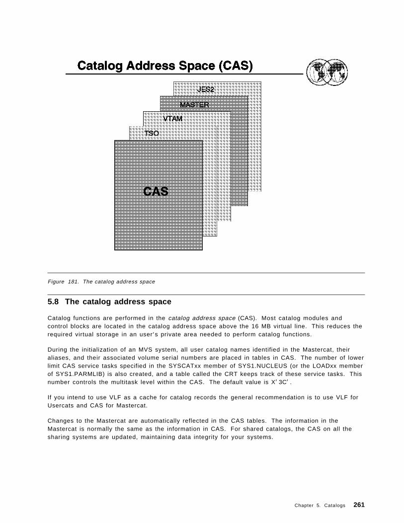
Figure 181. The catalog address space
5.8 The catalog address space
Catalog functions are performed in the catalog address space (CAS). Most catalog modules andcontrol blocks are located in the catalog address space above the 16 MB virtual line. This reduces therequired virtual storage in an user ′s private area needed to perform catalog functions.
During the initialization of an MVS system, all user catalog names identified in the Mastercat, theiraliases, and their associated volume serial numbers are placed in tables in CAS. The number of lowerlimit CAS service tasks specified in the SYSCATxx member of SYS1.NUCLEUS (or the LOADxx memberof SYS1.PARMLIB) is also created, and a table called the CRT keeps track of these service tasks. Thisnumber controls the multitask level within the CAS. The default value is X′ 3C′ .
If you intend to use VLF as a cache for catalog records the general recommendation is to use VLF forUsercats and CAS for Mastercat.
Changes to the Mastercat are automatically reflected in the CAS tables. The information in theMastercat is normally the same as the information in CAS. For shared catalogs, the CAS on all thesharing systems are updated, maintaining data integrity for your systems.
Chapter 5. Catalogs 261
5.8.1 Restarting the catalog address space
Restarting the CAS should be considered only as a final option before IPLing a system. Never tryrestarting CAS unless an IPL is your only other option. A system failure caused by catalogs, or a CASstorage shortage due to FREEMAIN failures, might require you to use MODIFY CATALOG,RESTART to restartCAS in a new address space.
Never use RESTART to refresh catalog or VVDS control blocks or to change catalog characteristics.Restarting CAS is a drastic procedure, and if CAS cannot restart, you will have to IPL the system.
Note: It is possible that a catalog request, currently being processed, cannot be properly retried afterbeing interrupted by these commands. Use these commands when all other means of correcting anongoing catalog error have failed.
When you issue MODIFY CATALOG,RESTART, the CAS mother task is abended with abend code 81A, andany catalog requests in process at the time are redriven.
The restart of CAS in a new address space should be transparent to all users. However, even when allrequests are redriven successfully and receive a return code of zero, the system might produceindicative dumps on the console, the system log, and on user job logs. There is no way to suppressthese indicative dumps.
262 ABCs of OS/390 System Programming

Figure 182. Backup procedures
5.9 Backup proceduresThe two parts of an ICV catalog, the BCS and the VVDS, require different backup techniques: the BCScan be backed up like any other data set, whereas the VVDS can only be backed up as part of avolume dump. The entries in the VVDS and VTOC are backed up when the data sets they describe areexported with access method services, logically dumped with DFSMSdss, or backed up withDFSMShsm.
5.9.1 Backing up a BCS (Mastercat or Usercat)
You can use the access method services EXPORT command, the DFSMSdss logical DUMP command, orthe DFSMShsm BACKDS command to back up a BCS. You can later recover the backup copies using thesame utility used to create the backup; the access method services IMPORT command for exportedcopies; the DFSMSdss RESTORE command for logical dump copies; and the DFSMShsm RECOVERcommand for DFSMShsm backups.
The copy created by these utilities is a portable sequential data set that can be stored on a tape ordirect access device, which can be of a different device type than the one containing the sourcecatalog.
When these commands are used to back up a BCS, the aliases of the catalog are saved in the backupcopy. The source catalog is not deleted, and remains as a fully functional catalog. The relationshipsbetween the BCS and VVDSs are unchanged.
Chapter 5. Catalogs 263

You cannot permanently export a catalog by using the PERMANENT parameter of EXPORT. TheTEMPORARY option is used even if you specify PERMANENT or allow it to default. PERMANENTspecifies that the cluster or alternate index is to be deleted from the original system. Its storage spaceis freed. If its retention period has not yet expired, you must also code PURGE.
Note: You cannot use IDCAMS REPRO or other copying commands to create and recover BCS backups.
5.9.2 Backing up a VVDSThe VVDS should not be backed up as a data set to provide for recovery. To back up the VVDS, backup the volume containing the VVDS, or back up all data sets described in the VVDS (all VSAM andSMS-managed data sets). If the VVDS ever needs to be recovered, recover the entire volume, or allthe data sets described in the VVDS.
You can use either DFSMSdss or DFSMShsm to back up and recover a volume or individual data setson the volume.
5.9.3 Backing up a Mastercat
A Mastercat can be backed up as any other BCS. You should use EXPORT, DFSMSdss, or DFSMShsmfor the backup. Another way to provide a backup for the Mastercat is to create an alternate Mastercat.For information on defining and using an alternate Mastercat, see DFSMS/MVS Version 1 Release 4:Managing Catalogs, SC26-4914.
You should also make periodic volume dumps of the Mastercat′s volume. This dump can later be usedby the stand-alone version of DFSMSdss to restore the Mastercat if you cannot access the volume fromanother system.
264 ABCs of OS/390 System Programming

Figure 183. Recover procedures
5.10 Recovery procedures
Normally, a BCS is recovered separately from a VVDS. A VVDS usually does not need to berecovered, even if an associated BCS is recovered. However, if you need to recover a VVDS, and aBCS resides on the VVDS′s volume, you must recover the BCS as well. If possible, you should exportthe BCS before recovering the volume, and then recover the BCS from the exported copy. Thisensures a current BCS.
Before recovering a BCS or VVDS, try to recover damaged records. If damaged records can be rebuilt,you can avoid a full recovery. BCS records can be recovered using the access method servicesDELETE and DEFINE commands with appropriate parameters. VVDS and VTOC records can be recoveredusing the DELETE command and by recovering the data sets on the volume.
You can recover a BCS that was backed up with the access method services EXPORT command, theDFSMSdss logical DUMP command, or the DFSMShsm BACKDS command or automatic backup. Torecover the BCS, use the IDCAMS IMPORT command, the DFSMSdss RESTORE command, or theDFSMShsm RECOVER command.
When you recover a BCS using these commands, you do not need to delete and redefine the targetcatalog unless you want to change the catalog ′s size or other characteristics, or unless the BCS isdamaged in such a way as to prevent the usual recovery. The recovered catalog is reorganized whenyou use IMPORT or RECOVER, but not when you use RESTORE.
Chapter 5. Catalogs 265

Aliases to the catalog can be defined if you use DFSMSdss, DFSMShsm, or if you specify ALIAS on theIMPORT command. If you have not deleted and redefined the catalog, all existing aliases aremaintained, and any aliases defined in the backup copy are redefined if they are not already defined.
Lock the BCS before you try to recover a BCS. After you recover the catalog, update the BCS with anychanges which have occurred since the last backup You can use the access method services DIAGNOSEcommand to identify certain unsynchronized entries.
When locking a catalog we recommend that you restrict access to a catalog when you are recovering itor when you are performing other maintenance procedures which involve redefining the catalog. If youdo not restrict access to the catalog (by locking it, by terminating user sessions, or by anothermethod), users might be able to update the catalog during recovery or maintenance and create a dataintegrity exposure. Locking the catalog eliminates the need to terminate user sessions during catalogrecovery or maintenance.
In addition, you can only lock integrated user catalogs. You cannot lock a master catalog. While thecatalog is locked, unauthorized requests to access the catalog fail with a return code indicating thatthe catalog is temporarily unavailable. Jobs entered with JCL fail with a JCL error. You cannot makeJCL jobs wait until the catalog is unlocked. The catalog is also unavailable to any system that sharesthe catalog.
You can also use the Integrated Catalog Forward Recovery Utility (ICFRU) to recover a damagedcatalog to a correct and current status. This utility uses system management facilities (SMF) recordsthat record changes to the catalog, updating the catalog with changes made since the BCS was backedup. ICFRU can also be used with shared catalogs or master catalogs, if the master catalog is not beingused as a master at the time. We recommend the use of ICFRU to avoid the loss of some catalog dataeven after the recovery.
For further information about recovery procedures, see DFSMS/MVS Version 1 Release 4: ManagingCatalogs, SC26-4914.
266 ABCs of OS/390 System Programming

Figure 184. RACF
5.11 Protecting catalogs
The protection of data includes:
• Data security: the safety of data from theft or intentional destruction
• Data integrity: the safety of data from accidental loss or destruction
Data can be protected either indirectly, by preventing access to programs which can be used to modifydata, or directly, by preventing access to the data itself. Catalogs and cataloged data sets can beprotected in both ways.
To protect your catalogs and cataloged data, use the Resource Access Control Facility (RACF) orsimilar product.
5.11.1 RACF authorization checking
RACF provides a software access control measure you can use in addition to or instead of VSAMpasswords. RACF protection and password protection can coexist for the same data set.
To open a catalog as a data set, you must have ALTER authority and APF authorization. When definingan SMS-managed data set, the system only checks to make sure the user has authority to the data setname and SMS classes and groups. The system selects the appropriate catalog, without checking theuser ′s authority to the catalog. You can define a data set if you have ALTER or OPERATIONS authorityto the applicable data set profile.
Chapter 5. Catalogs 267

Deleting any type of RACF-protected entry from a RACF-protected catalog requires ALTERauthorization to the catalog or to the data set profile protecting the entry being deleted. If a non-VSAMdata set is SMS-managed, RACF does not check for DASDVOL authority. If a non-VSAM,non-SMS-managed data set is being scratched, DASDVOL authority is also checked.
For ALTER RENAME, the user is required to have the following two types of authority:
• ALTER authority to either the data set or the catalog
• ALTER authority to the new name (generic profile) or CREATE authority to the group
Be sure that RACF profiles are correct after you use REPRO MERGECAT or CNVTCAT on a catalog thatuses RACF profiles. If the target and source catalogs are on the same volume, the RACF profilesremain unchanged.
Non-VSAM tape data sets defined in an integrated catalog facility catalog can be protected by:
• Controlling access to the tape volumes
• Controlling access to the individual data sets on the tape volumes
5.11.2 Profiles
To control the ability to perform functions associated with storage management, define profiles in theFACILITY class whose profile names begin with STGADMIN (storage administration). For a completelist of STGADMIN profiles, see DFSMS/MVS DFSMSdfp Storage Administration Reference, SC26-4920.Examples of some profiles are:
STGADMIN.IDC.DIAGNOSE.CATALOGSTGADMIN.IDC.DIAGNOSE.VVDSSTGADMIN.IDC.EXAMINE.DATASET
268 ABCs of OS/390 System Programming

Figure 185. Merging catalogs
5.12 Merging catalogs
You might find it beneficial to merge catalogs, if you have many small or seldom-used catalogs. Anexcessive number of catalogs can complicate recovery procedures and waste resources such as CASstorage, tape mounts for backups, and system time performing backups.
Merging catalogs is accomplished in much the same way as splitting catalogs. The only differencebetween splitting catalogs and merging them is that in merging, you want all the entries in a catalog tobe moved to different catalog, so that you can delete the obsolete catalog.
The following steps should be followed to merge two integrated catalog facility catalogs:
1. Use ALTER LOCK to lock both catalogs.
2. Use LISTCAT to list the aliases for the catalog you intend to delete after the merger. Use theOUTFILE parameter to delete a data set to contain the output listing.
3. Use EXAMINE and DIAGNOSE to ensure that the catalogs are error-free. Fix any errors indicated.
4. Use REPRO MERGECAT without specifying the ENTRIES or LEVEL parameter. The OUTDATASETparameter specifies the catalog that you are keeping after the two catalogs are merged. Thisstep can take a long time to complete.
5. Use the listing created in step 2 to create a sequence of DELETE ALIAS and DEFINE ALIAScommands to delete the aliases of the obsolete catalog, and to redefine the aliases as aliasesof the catalog you are keeping. If this step fails for any reason, see “Recovering from a REPRO
Chapter 5. Catalogs 269

MERGECAT Failure” in topic 4.2.3 of DFSMS/MVS Version 1 Release 4: Managing Catalogs,SC26-4914.
6. Use DELETE USERCATALOG to delete the obsolete catalog. Specify RECOVERY on the DELETEcommand.
7. If your catalog is shared, run the EXPORT DISCONNECT command on each shared system toremove unwanted user catalog connector entries.
8. Use ALTER UNLOCK to unlock the remaining catalog.
You can also merge entries from one tape volume catalog to another using REPRO MERGECAT. REPROretrieves tape library or tape volume entries and redefines them in a target tape volume catalog. Inthis case, VOLUMEENTRIES needs to be used to correctly filter the appropriate entries. The LEVELparameter is not allowed when merging tape volume catalogs.
270 ABCs of OS/390 System Programming

Figure 186. Splitting catalogs
5.13 Splitting a catalog
You can split a catalog to create two catalogs or to move a group of catalog entries, if you determinethat a catalog is either unacceptably large or that it contains too many entries for critical data sets.
If the catalog is unacceptably large (a catalog failure would leave too many entries inaccessible), thenyou can split the catalog into two catalogs. If the catalog is of an acceptable size but contains entriesfor too many critical data sets, then you can simply move entries from one catalog to another.
To split a catalog or move a group of entries, use the access method services REPRO MERGECATcommand. The following steps should be followed to split a catalog or to move a group of entries:
1. Use ALTER LOCK to lock the catalog. If you are moving entries to an existing catalog, lock it aswell.
2. If you are splitting a catalog, define a new catalog with DEFINE USERCATALOG LOCK.
3. Use LISTCAT to obtain a listing of the catalog aliases which you are moving to the new catalog.Use the OUTFILE parameter to define a data set to contain the output listing.
4. Use EXAMINE and DIAGNOSE to ensure that the catalogs are error-free. Fix any errors indicated.
5. Use REPRO MERGECAT to split the catalog or move the group of entries. When splitting a catalog,the OUTDATASET parameter specifies the catalog created in step 2. When moving a group ofentries, the OUTDATASET parameter specifies the catalog which is to receive the entries. Thisstep can take a long time to complete.
Chapter 5. Catalogs 271

Use the ENTRIES or LEVEL parameters to specify which catalog entries are to be removed fromthe source catalog and placed in the catalog specified in OUTDATASET.
If this step fails for any reason, see “Recovering from a MERGECAT Failure” in topic 4.2.3 ofDFSMS/MVS Version 1 Release 4: Managing Catalogs, SC26-4914.
6. Use the listing created in step 3 to create a sequence of DELETE ALIAS and DEFINE ALIAScommands for each alias. These commands delete the alias from the original catalog, andredefine them as aliases for the catalog which now contains entries belonging to that aliasname.
The DELETE ALIAS/DEFINE ALIAS sequence must be run on each system that shares the changedcatalogs.
7. Unlock both catalogs using ALTER UNLOCK.
272 ABCs of OS/390 System Programming

Figure 187. Catalog performance
5.14 Catalog performance
Performance should not be your main consideration when you define catalogs. It is more important tocreate a catalog configuration which allows easy recovery of damaged catalogs with the least amountof system disruption. However, there are several options you can choose to improve catalogperformance without affecting the recoverability of a catalog.
5.14.1 Factors affecting catalog performance
The main factors affecting catalog performance are the amount of I/O required for the catalog and thesubsequent amount of time it takes to perform the I/O. These factors can be reduced by cachingcatalogs in special caches used only by catalogs. If a catalog is cached, the reduced I/O to the catalogreduces the effect of other factors on catalog performance.
If the Mastercat only contains entries for catalogs, catalog aliases, and system data sets, the entireMastercat is read into CAS virtual storage during system initialization. Because the Mastercat, ifproperly used, is rarely updated, the performance of the Mastercat is not appreciably affected by I/Orequirements.
5.14.2 Eliminating JOBCAT and STEPCAT DD
Another good reason for not using STEPCAT and JOBCAT is because they have poor performance.
Chapter 5. Catalogs 273

5.14.3 Caching catalogs
The simplest method of improving catalog performance is to use cache to maintain catalog recordswithin CAS private area address space or VLF data space.
Two kinds of cache are available exclusively for catalogs. The in-storage catalog (ISC) cache iscontained within the catalog address space (CAS). The catalog data space cache (CDSC) is separatefrom CAS and uses the MVS VLF component which stores the cached records in a data space. Bothtypes of cache are optional, and each can be cancelled and restarted without an IPL.
Although you can use both types of catalog cache, you cannot cache a single catalog in both types ofcache simultaneously. You must decide which catalogs benefit the most from each type of cache.
Catalog records are cached in the ISC or CDSC under the following conditions:
• For Mastercat, all records accessed sequentially or by key are cached except for alias records.Alias records are kept in a separate table in main storage.
• For Usercats, only records accessed by key are cached, that is by data set name—which is thenormal type of access.
• For each catalog, the records are cached in the CDSC if you have indicated the catalog is to useCDSC. Otherwise, the records are cached in the ISC (Usercat included) unless you have stoppedthe ISC for the catalog. If you stop both the CDSC and the ISC for a catalog, then records are notcached.
In-storage cache (ISC)
The in-storage catalog cache resides in the private area of the CAS. It is the default catalog cache.Each Usercat cached in ISC is given a fixed amount of space for cached records. When a Usercatreaches its allotted space in the ISC, the least recently used record is removed from the ISC to makeroom for the new entry.
Catalogs which are not frequently updated use the ISC most effectively. The Mastercat is ideally suitedfor ISC because master catalog records are infrequently updated. The performance of the ISC isaffected if the catalog is shared with another system.
Mastercat, unlike Usercats, are not limited to a set amount of CAS virtual storage. All eligible recordsin the Mastercat are cached in the ISC as they are read.
Thus, you should keep the number of entries in the master catalog to a minimum, so that the ISC forthe master does not use an excessive amount of main storage.
Since ISC is the default catalog cache, catalogs are cached in the ISC unless you specify that thecatalog is to use CDSC, or unless you use the MODIFY CATALOG operator command to remove the catalogfrom the ISC.
Catalog data space cache (CDSC)
CDSC resides in a data space which you define with the COFVLFxx member of SYS1.PARMLIB. TheCDSC uses the virtual look-aside facility (VLF), which can be started by using the START VLF operatorcommand. In the COFVLFxx you should declare:
• NAME(IGGCAS)
• EMAJ(catname)...: for the names of the catalogs to be cached
• MAXVIRT({ 4096|size}): specifying the maximum virtual storage that VLF can use to cache catalogrecords.
274 ABCs of OS/390 System Programming

You can add catalogs to the CDSC only by changing the COFVLFxx member to specify the catalogs,stopping VLF, then starting VLF. Because this interrupts servicing on the existing CDSC, catalogperformance might be degraded for a while.
The CDSC can concurrently be used for any catalog which is not using the ISC. A single catalogcannot use both the CDSC and the ISC. Unlike the ISC, catalogs cached in the CDSC are not limited toa specific amount of data space virtual storage. A catalog caches records until no space is left in thedata space cache. Once the data space cache is full, the space occupied by the record least used isremoved to make room for new records.
Chapter 5. Catalogs 275

Figure 188. Monitoring the CAS
5.14.4 Monitoring the CAS
Using the MODIFY CATALOG,REPORT command, you can obtain general information about the catalogaddress space. This information can be used to evaluate your current catalog environment setup. Ifyou determine that your current setup is inadequate, you can change it with another MODIFY CATALOGcommand, or by changing the SYSCATxx member of SYS1.NUCLEUS.
The visual shows an example of the output of an unqualified MODIFY CATALOG,REPORT command.
There is information about the service tasks available to process catalog requests. In this example,you can see that the service task lower limit is adequate for the current number of tasks. The servicetask upper limit defaults to X′ B4′ , and can be changed by the MODIFY CATALOG,TASKMAX command. Thehighest number of service tasks is equal to the highest value the current number of tasks field hasreached.
Catalog management creates tasks as necessary as the current number of tasks exceeds the servicetask lower limit. As catalog requests subside, the number of tasks attached and available forprocessing requests is reduced until the lower limit is reached.
The maximum number of open catalogs is the value set by the MODIFY CATALOG,CATMAX command. Thisis the maximum number of catalogs, in hexadecimal, which might be open to CAS simultaneously. Ifthe maximum is reached, catalog management closes the least recently used catalog before openinganother catalog. Normally, a catalog remains open once it has be opened.
276 ABCs of OS/390 System Programming

The alias table available entry indicates whether there is a problem with the catalog alias table. Thisfield should always say YES. If it says NO try restarting the catalog address space. Performance isaffected when catalog management does not have catalog aliases in the catalog alias table.
For more details on the F CATALOG,REPORT output, refer to DFSMS/MVS Version 1 Release 4: ManagingCatalogs, SC26-4914.
Chapter 5. Catalogs 277

Figure 189. Monitoring the CAS performance
5.14.5 Monitoring the CAS performance
This visual shows the partial report obtained by the execution of the MVS command:
MODIFY CATALOG,REPORT,PERFORMANCE
This command can be useful in identifying performance problems that you suspect are related tocatalog processing. For example, if the average time for ENQs that is shown in the report seemsexcessive, it might indicate some problems in the GRS configuration, or parameter specifications.High I/O times might indicate problems with:
• Channel or device load
• Volumes that are suffering a high number of I/O errors
• Volumes that have excessively high RESERVE rates or long RESERVE durations
278 ABCs of OS/390 System Programming

Figure 190. Monitoring the CDSC performance
5.14.6 Monitoring the CDSC performance
In order to evaluate the catalog data space cache, use the command:
MODIFY CATALOG,REPORT,CACHE
You can use this command to evaluate the cache performance for a specified catalog, or for allcatalogs that are currently being cached. The numbers shown in this report are in decimal.
When you evaluate the cache performance for a catalog, you need to consider how long the cataloghas been using the cache. If the cache has only been available for a catalog for an hour, the hit ratiowill likely be low. However, if the catalog has been using the cache for a week, expect a good hit ratio.The hit ratio is an indication of cache usage while the cache is available. The values do notaccumulate between performing IPLs, stopping and starting VLF, or restarting the catalog addressspace.
Chapter 5. Catalogs 279

Figure 191. Use mult iple catalogs
5.15 Using multiple catalogs
Multiple catalogs on multiple volumes may perform better than fewer catalogs on fewer volumes. Thisis because of the interference between requests to the same catalog; for example, a single sharedcatalog being locked out by another system in the sysplex. This situation can occur if some otherapplication issues a RESERVE against the volume that has nothing to do with catalog processing.Another reason can be that there is more competition to use the available volumes, and thus more I/Ocan be in progress concurrently.
If you are not using VLF for caching, there is a limited amount of cache storage assigned to eachcatalog in CAS. Large catalogs may suffer from this fixed limit and receive less benefit from non-VLFcaching than an environment with more smaller catalogs.
Multiple catalogs may reduce the impact of the loss of a catalog by:
• Reducing the time necessary to recreate any given catalog
• Allowing multiple catalog recovery jobs to be in process at the same time
Recovery from a pack failure is dependent on the total amount of catalog information on avolume—regardless of whether this information is stored in one or many catalogs
280 ABCs of OS/390 System Programming

Figure 192. Sharing catalogs
5.15.1 Sharing catalogs
If a BCS catalog is defined with share options (3 4), and if it resides on a shared device, catalogmanagement considers the catalog a shared catalog, including the correspondent VVDSs.
If a catalog is not really shared with another system, move the catalog an unshared device or alter itsshare options to (3 3). To prevent potential catalog damage, never place a catalog with share options(3 3) on a shared device.
The volume containing the VVDS is reserved before the I/O is performed.
5.15.1.1 Guaranteeing the ISC/CDSC current information
Before each physical access to a shared catalog, special I/O checking is performed to ensure that theISC or CDSC contains current information. Checking also ensures that the access method controlblocks for the catalog are updated in the event the catalog has been extended, or otherwise alteredfrom another system. This checking maintains data integrity. It also affects performance because inorder to keep this integrity, for every catalog access, a special VVR in the shared catalog must be readbefore using the ISC or CDSC version of the BCS record. This access implies a DASD reserve and I/Ooperations.
Changes to shared catalogs are handled differently depending on whether the catalog uses the ISC orthe CDSC:
Chapter 5. Catalogs 281

• If a catalog uses the ISC and a sharing system updates a record as indicated by the specialVVR—any record, even if the record is not cached in this system′s ISC—catalog managementreleases the entire ISC for the catalog and creates a new ISC for the catalog. Individual recordschanged by a sharing system are not identified and updated for ISC catalogs.
• The CDSC, however, can identify individual records which a sharing system has updated byexecuting I/O operations. The special VVR contains a wrap table with the keys of the 90 mostrecent records updated/added/deleted. For every catalog record read, the catalog VVR must beread. If the BCS records cached in CDSC on that system are not changed, they are still valid. Ifthe table of updated records in the VVR has wrapped since the last time the catalog was accessedby this system, the complete CDSC cache is purged for this catalog. If not, only those recordsindicated in VVR are discarded from CDSC cache. This requires I/O to VVDS for each BCS I/O. Italso generates Reserves or GRS traffic.
Thus, when a sharing system updates a record, the CDSC space used by the catalog is notnecessarily totally released.
282 ABCs of OS/390 System Programming

Figure 193. DFSMS enhanced catalog sharing
5.15.2 DFSMS enhanced catalog sharing
If the catalog has been defined to support DFSMS/MVS 1.5 Enhanced Catalog Sharing (ECS) by theECSHARING attribute, most of the overhead associated with shared catalog is eliminated.
ECS uses a cache Coupling Facility structure to keep the special VVR. Also the Coupling Facilitystructure (as defined in CFRM) keeps a copy of the updated records. A new ENQ is used to indicatethat a catalog is being used in ECS mode. As you can see, there is no more I/O to read the catalogVVR in order to verify the updates. In addition, the eventual modifications are also kept in theCoupling Facility structure, thus avoiding more I/O.
A new attribute, ECSHARING, is available on the IDCAMS DEFINE and ALTER commands. Setting thisattribute on makes a catalog eligible for sharing using the ECS protocol, as opposed to the VVDS/VVRprotocol. However, catalog management does not actually use the ECS protocol unless:
• There is an active connection to the ECS cache structure, and
• ECS mode has been activated by either the MODIFY CATALOG, ECSHR(AUTOADD) command or the MODIFYCATALOG, ECSHR(ADD...) command.
ECS provides saves about 50 percent in elapsed time and an enormous reduction in ENQ/Reserves.
Chapter 5. Catalogs 283

284 ABCs of OS/390 System Programming

Appendix A. OS/390 installation and customization
This appendix shows the SYS1.PARMLIB members and their functions.
A.1 SYS1.PARMLIB members
Table 5 (Page 1 of 3). Overview of parmlib members
Member Description
ADYSETxx Parameters that control dump analysis and elimination (DAE) processing.
ALLOCxx Parameters that control installation defaults for allocation values.
APPCPMxx Parameters that define or modify the APPC/MVS configuration.
ASCHPMxx Parameters that define scheduling information for the ASCH transaction scheduler.
BLSCECT Parameters that control dump formatting performed by IPCS, and by the system (through theABEND and SNAP macros).
BLSCUSER Parameters that specify IPCS customization.
BPXPRMxx Parameters that control the OS/390 UNIX System Services environment and the hierarchicalfile system (HFS). The system uses these values when initializing the OS/390 UNIX SystemServices kernel.
CLOCKxx Parameters that control operator prompting to set the TOD clock, specifying the differencebetween the local time and GMT, and ETR usage.
CNGRPxx Parameters that define console groups as candidates for switch selection if a console fails.
CNLcccxx Defines how translated messages are to be displayed at your installation.
COFDLFxx Allows a program to store DLF objects that can be shared by many jobs in virtual storagemanaged by Hiperbatch.
COFVLFxx Allows an authorized program to store named objects in virtual storage managed by VLF.
COMMNDxx Commands to be issued by the control program immediately after initialization. JEScommands may not be included.
CONFIGxx Allows the installation to define a standard configuration that is compared with the currentconfiguration and to reconfigure processors, storage, and channel paths.
CONSOLxx Parameters to define an installation′s console configuration, initialization values forcommunications tasks, the default routing codes for all WTO/WTOR messages that have noneassigned, and the characteristics of the hardcopy message set. CONSOLxx also containsparameters that define the hardcopy medium and designate the alternate console group forhardcopy recovery.
COUPLExx Describes the systems complex (sysplex) environment for the system.
CSVLLAxx Allows an installation to list the entry point name or LNKLST libraries that can be refreshedby the ′ MODIFY LLA, UPDATE=xx′ command.
CSVRTLxx Defines the run-time library services (RTLS) configuration. CSVRTLxx can be used to specifynames of libraries to be managed, as well as storage limits for caching modules from thelibraries.
CTncccxx Specifies component trace options.
DEVSUPxx Allows an installation to specify whether data will be stored in a compacted format on a 3480or 3490 tape subsystem with the Improved Data Recording Capability feature.
DIAGxx Contains diagnostic commands that control the common storage tracking andGETMAIN/FREEMAIN/STORAGE (GFS) trace functions.
EXITxx Allows an installation to specify installation exits for allocation decisions.
Copyright IBM Corp. 2000 285

Table 5 (Page 2 of 3). Overview of parmlib members
Member Description
EXSPATxx Allows an installation to specify actions taken to recover from excessive spin conditionswithout operator involvement.
GRSCNFxx: Configuration parameters for systems that are to share resources in a global resourceserialization complex.
GRSRNLxx Resource name lists (RNLs) that the system uses when a global resource serializationcomplex is active.
GTFPARM Parameters to control GTF.
IEAABD00: Default parameters for an ABEND dump when a SYSABEND DD statement has been specified.
IEAAPFxx Names of authorized program libraries.
IEAAPPxx Names of authorized installation-written I/O appendage routines.
IEACMD00 IBM-supplied commands that are processed during system initialization.
IEADMCxx Parameters for DUMP command.
IEADMP00 Default parameters for an ABEND dump when SYSUDUMP DD statement has been specified.
IEADMR00 Default parameters for an ABEND dump when SYSMDUMP DD statement has been specified.
IEAFIXxx Names of modules to be fixed in central storage for the duration of the IPL.
IEAICSxx Parameters of an installation control specification that associate units of work (transactions)with performance groups. Performance groups are used by the system resources manager tocontrol and report on transactions.
IEAIPSxx Parameters of an installation performance specification that control the Workload Manager ofthe System Resources Manager.
IEALPAxx Names of reenterable modules that are to be loaded as a temporary extension to the PLPA.
IEAOPTxx Parameters that control resource and workload management algorithms in the SystemResources Manager.
IEAPAKxx “Pack List” names of groups of modules in the LPALST concatenation that the system willload between page boundaries to minimize page faults.
IEASLPxx Contains valid SLIP commands.
IEASVCxx Allows the installation to define its own SVCs in the SVC table.
IEASYMxx Specifies, for one or more systems in a multisystem environment, the static system symbolsand suffixes of IEASYSxx members that the system is to use. One or more IEASYMxxmembers are selected using the IEASYM parameter in the LOADxx parmlib member.
IEASYSxx System parameters that are valid responses to the SPECIFY SYSTEM PARAMETERSmessage. Multiple system parameter l ists are valid. The list is chosen by the operator SYSPparameter or through the SYSPARM statement of the LOADxx parmlib member.
IECIOSxx: Parameters that control missing interrupt handler (MIH) intervals and update hot I/Odetection table (HIDT) values.
IEFSSNxx Parameters that identify what subsystems are to be initialized.
IFAPRDxx Parameters that define a product enablement policy.
IGDDFPKG One or more statements that specify which DFSMS/MVS functional components andseparately orderable features are licensed for use on a particular MVS system or across asysplex.
IGDSMSxx Initialize the Storage Management Subsystem (SMS) and specify the names of the activecontrol data set (ACDS) and the communications data set (COMMDS).
IKJPRMxx TIOC parameters that control TSO/TCAM time sharing buffers.
IKJTSOxx For TSO/E, specifies authorized commands and authorized programs, programs that areauthorized when called through the TSO service facility, commands that may not be issued inthe background, and defaults for SEND and LISTBC processing.
286 ABCs of OS/390 System Programming

Table 5 (Page 3 of 3). Overview of parmlib members
Member Description
IPCSPRxx Parameters that are used during an IPCS session.
IVTPRM00 Sets Communications Storage Manager (CSM) parameters.
LNKLSTxx List of data sets to be concatenated to form the LNKLST concatenation. You can also usePROGxx to define the concatenation.
LOADxx Specifies data sets MVS uses to configure your system.
LPALSTxx List of data sets to be concatenated to SYS1.LPALIB from which the system builds thepageable LPA (PLPA).
MMSLSTxx Specifies information that the MVS message service (MMS) uses to control the languagesthat are available in your installation.
MPFLSTxx Parameters that the message processing facility uses to control message processing anddisplay.
MSTJCLxx Contains the master scheduler job control language (JCL) that controls system initializationand processing.
NUCLSTxx Specifies members of SYS1.NUCLEUS to be included in, or excluded from, the nucleus regionat IPL-time.
PFKTABxx Parameters contain the definitions for program function key tables (PFK tables).
PROGxx: Contains statements that define the format and contents of the APF-authorized programlibrary list, control the use of installation exits and exit routines, define the LNKLSTconcatenation, and specify alternate data sets for SYS1.LINKLIB, SYS1.MIGLIB, andSYS1.CSSLIB to appear at the beginning of the LNKLST concatenation and SYS1.LPALIB toappear at the beginning of the LPALST concatenation.
SCHEDxx Provides centralized control over the size of the master trace table, the completion codes tobe eligible for automatic restart, and programs to be included in the PPT.
SMFPRMxx Parameters that define SMF options.
TSOKEYxx VTIOC parameters that are used by TSO/VTAM time sharing.
VATLSTxx Volume attribute list that defines the mount and use attributes of direct access volumes.
XCFPOLxx Specifies the actions that a system in a sysplex on PR/SM is to take when another system inthe sysplex becomes inactive.
Notes:
1. These parameters can be listed at IPL: APF, DUMP, FIX, ICS, MLPA, SYSP, and OPT.
2. The only mandatory parameter is PAGE. Other parameters have coded defaults.
3. Performance-oriented parameters in IEASYSxx: APG, CMD, FIX, IPS, MLPA, OPT, REAL, RSU,WTOBFRS, WTORPLY.
4. System symbols in COMMNDxx and MSTJCLxx are processed differently than system symbols inother parmlib members. See the descriptions of COMMNDxx and MSTJCLxx in this book fordetails.
A.2 IEASYSxx SYS1.PARMLIB parameters
Table 6 (Page 1 of 5). Overview of IEASYSxx parameters
Parameter Use of the parameter
ALLOC Completes the names of one or more parmlib members (ALLOCxx) that describe installationdefaults for allocation parameters.
Appendix A. OS/390 installation and customization 287

Table 6 (Page 2 of 5). Overview of IEASYSxx parameters
Parameter Use of the parameter
APF Names the parmlib member (IEAAPFxx) that contains authorized library names. IEAAPFxx canspecify only a static APF list, which can only be updated at IPL and contain a maximum of 255entries.
CLOCK Completes the name of the parmlib member (CLOCKxx) that prompts the operator to initializethe TOD clock during NIP, and specifies the difference between the local time and GreenwichMean Time (GMT).
CLPA Causes NIP to load the link pack area with the modules contained in the LPALSTconcatenation. Also, CLPA purges VIO data set pages that were used in the previouslyinitialized system. Thus, CLPA implies CVIO.
CMB Specifies the I/O device classes for which measurement data is to be collected, in addition tothe DASD and tape device classes.
CMD Completes the name of the parmlib member (COMMNDxx) that contains commands to beissued internally during master scheduler initialization.
CON Completes the name of the parmlib member (CONSOLxx) that centralizes control of theconsole configuration for your installation. CONSOLxx also contains the initialization valuesfor communication tasks, the characteristics for the hard-copy log, and default routing codesfor messages that do not have routing information. The CON parameter is also used to allowa system with both JES2 and any level of JES3 installed to run with JES2. This allows functionthat is incompatible with JES3 to operate successfully.
COUPLE Completes the name of the parmlib member (COUPLExx) that describes the sysplexenvironment for the initializing system.
CSA Specifies the sizes of the virtual common service area and extended common service area.
CSCBLOC Determines the location of the CSCB control block chain.
CVIO Deletes previously used VIO data set pages from the paging space. This parameter isautomatically included when CLPA is specified.
DEVSUP Completes the name of the parmlib member (DEVSUPxx) that specifies installation defaultsfor device support options.
DIAG Completes the names of one or more parmlib members (DIAGxx) that specify whether theCSA/ECSA or SQA/ESQA tracking functions are turned on or off, whetherGETMAIN/FREEMAIN/STORAGE (GFS) trace is turned on or off, and the trace records to beincluded in GFS trace output.
DUMP Specifies whether SYS1.DUMP data sets for SVC dump are to be on direct access device(s).This parameter can also indicate that no SYS1.DUMP data sets are to be made available forSVC dumps.
DUPLEX Specifies a duplex page data set name or overrides the existing duplex data set name. Thisparameter is ignored on quick starts and warm starts (non-CLPA IPLs).
EXIT Completes the name of one or more parmlib members (EXITxx) that contains the entry pointsand names of allocation installation exits.
FIX Completes the name of one or more parmlib members (IEAFIXxx) that contain names ofmodules that are to be placed in a fixed LPA that lasts for the duration of the IPL.
GRS Specifies whether the system is to participate in a global resource serialization complex.
GRSCNF Completes the name of the parmlib member (GRSCNFxx) that contains the informationneeded to initialize a system that is to be part of a global resource serialization complex.
GRSRNL Completes the name of one or more parmlib members (GRSRNLxx) that contain resourcename lists (RNLs) or specifies that no RNLs are to be used in the complex.
ICS Completes the name of the parmlib member (IEAICSxx) that contains the installation controlspecification. The installation control specification is used by the system resources manager(SRM) to assign performance groups.
288 ABCs of OS/390 System Programming

Table 6 (Page 3 of 5). Overview of IEASYSxx parameters
Parameter Use of the parameter
IOS Completes the name of the parmlib member (IECIOSxx) that contains missing interrupthandler (MIH) statements used to modify MIH intervals and HOTIO statements used to modifyrecovery actions specified in the hot I/O detection table (HIDT).
IPS Completes the name of the parmlib member (IEAIPSxx) from which the system resourcesmanager (SRM) will obtain the installation performance specification. The absence of anIPS= indicates that the system is to be IPLed in workload management goal mode.
LNK Completes the name of one or more parmlib members (LNKLSTxx) that contain names ofdata sets that are to be concatenated to SYS1.LINKLIB to form the LNKLST concatenation.You can also use PROG to specify the PROGxx member that defines the LNKLSTconcatenation.
LNKAUTH Specifies whether all data sets in the LNKLST concatenation are to be treated asAPF-authorized or whether only those that are named in the APF table are to be treated asAPF-authorized.
LOGCLS Specifies the JES output class for the log data sets.
LOGLMT Specifies the maximum number of WTLs (messages) for a log data set. When the limit isreached, the data set is scheduled for sysout processing.
LOGREC Specifies the logrec recording medium for error recording.
LPA Completes the name of one or more parmlib members (LPALSTxx) that contain names of datasets that are to be concatenated to SYS1.LPALIB for building the pageable LPA (PLPA andextended PLPA).
MAXCAD Specifies the maximum number of SCOPE=COMMON data spaces to be allowed during anIPL.
MAXUSER Specifies a value that the system uses (along with the RSVSTRT and RSVNONR parametervalues) to limit the number of jobs and started tasks that the system can run concurrentlyduring a given IPL.
MLPA Completes the name of one or more parmlib members (IEALPAxx) that names modules thatare to be placed in a modified LPA that lasts for the duration of the IPL.
MSTRJCL Completes the name of the MSTJCLxx data set that contains the JCL used to start the masterscheduler address space.
NONVIO Designates one or more local page data sets that are not to be used for VIO paging.
NSYSLX Specifies the number of linkage indexes (LXs), in addition to those in the system functiontable, to be reserved for system linkage indexes (LXs).
OMVS Specifies the parmlib member or members to use to locate the parmlib statements toconfigure the OS/390 UNIX System Services kernel.
OPI Indicates whether the operator is to be allowed to override particular parameters, or allparameters, contained in IEASYSxx.
OPT Completes the name of a parmlib member (IEAOPTxx) that contains parameters to be used byvarious algorithms of the system resources manager.
PAGE Gives the names of new page data sets to be used as additions to or replacements forexisting page data sets. The first-named data set is used for the PLPA and extended PLPApages. The second-named data set is used for MLPA and CSA. The third and all subsequentlynamed data sets are used as local page data sets. Replacement is possible only if theparameter is placed in IEASYSxx, and the operator selects this member by enteringSYSP=xx. The PAGE parameter, when specified by the operator, can only add temporarily(until the next cold or quick start) to a parmlib page data set list.
PAGTOTL Specifies the total number of page and swap data sets that can be allocated for the life of theIPL.
PAK Completes the name of one or more parmlib members (IEAPAKxx) that contain groups ofnames of modules in the LPALST concatenation that are processed together or in sequence.
Appendix A. OS/390 installation and customization 289

Table 6 (Page 4 of 5). Overview of IEASYSxx parameters
Parameter Use of the parameter
PLEXCFG Specifies the sysplex configuration into which the system is allowed to IPL.
PROD Completes the name of one or more parmlib members (IFAPRDxx) that define the enablementpolicy for products or product features that can be dynamically enabled under OS/390.
PROG Completes the name of one or more parmlib members (PROGxx) that specify the format andcontents of the APF-authorized library list. PROGxx can specify either a static or dynamic APFlist. A dynamic format allows users to update the APF list at any time during normalprocessing or at IPL. You can specify as many APF-authorized libraries as you need in adynamic APF list; there is no system-imposed maximum number. PROGxx also containsstatements that control the use of installation exits and installation exit routines.
You can also use PROGxx instead of LNKLSTxx to define the LNKLST concatenation andactivate it at IPL.
RDE Specifies that the reliability data extractor (RDE) feature is included. For information on RDE,see OS/390 MVS Diagnosis: Tools and Service Aids, LY28-1085 (available to IBM licensedcustomers only).
REAL Specifies the maximum amount of central storage, in 1 KB blocks, that can be allocated forconcurrent ADDRSPC=REAL jobs.
RER Specifies that the reduced error recovery procedures for magnetic tapes are in effect if theyare included on the OPTCD parameter of a data definition (DD) statement or on the DCBmacro instruction. If the DD statement or the DCB macro does not specify the reduced errorrecovery procedures, all requests for them are ignored.
RSU Specifies the number of central storage units to be made available for storagereconfiguration (either physical partitioning, or dividing storage into logical partitions underPR/SM).
RSVNONR Specifies the number of ASVT entries to be reserved for replacing those entries markednon-reusable for the duration of an IPL.
RSVSTRT Specifies the number of address space vector table (ASVT) entries to be reserved for addressspaces created in response to a START command.
RTLS Specifies the following for the RTLS configuration:
• Library names to be managed
• Module name to be managed
• Cache storage to hold libraries
• Library Volume Serial name
SCH Specifies a parmlib member (SCHEDxx) from which the master scheduler will obtain itsparameters. This member centralizes control over the size of the master trace table, theprogram properties table (PPT), and the completion codes that are eligible for automaticrestart.
SMF Specifies a parmlib member (SMFPRMxx) from which SMF will obtain its parameters.
SMS Specifies a parmlib member (IDGSMSxx) from which SMS will obtain its parameters when thesystem is initialized with partitioned data set extended (PDSE) support.
SQA Specifies the size of the virtual system queue area to be created at IPL (in addition to thesystem ′s minimum virtual SQA and extended SQA).
SSN Completes the name of the parmlib member IEFSSNxx, which contains the information to beused in identifying subsystems that are to be initialized.
SVC Completes the name of the parmlib member IEASVCxx, which contains the information aninstallation supplies to define its own SVCs. NIP processing places these SVCs in the SVCtable.
SWAP Specifies the names of new swap data sets to be used as additions to or replacements forexisting swap data sets.
290 ABCs of OS/390 System Programming

Table 6 (Page 5 of 5). Overview of IEASYSxx parameters
Parameter Use of the parameter
SYSNAME Specifies the name of the system being initialized. The name specified here is used by thesystem in various ways. For example:
• In a multisystem global resource serialization complex, SYSNAME identifies each systemin the complex.
• The system also uses this value to uniquely identify the originating system in messagesin the multiple console support (MCS) hard-copy log and in the display created by theDISPLAY R command.
• The value specified can be used in the IGDDFPKG member to identify a system for whicha particular DFSMS/MVS offering level is licensed.
SYSP Specifies one or more alternate system parameter lists (IEASYSxx) that are to be read by NIPin addition to IEASYS00. SYSP may be specified only by the operator.
VAL Names one or more parmlib members (VATLSTxx) that contain “mount” and “use” attributesof direct access devices.
VIODSN Specifies the VSAM data set name for storing information about journaled VIO data sets.
VRREGN Gives the default real-storage region size for an ADDRSPC=REAL job step that does nothave a REGION parameter in its JCL.
A.3 System data sets
Name Description
MasterCatalog
A required system data set that contains data sets and volume information necessary tolocate data sets and users.
IODF A VSAM data set that contains hardware and software configuration definitions.
SYSn.IPLPARM An optional partitioned data set that contains LOADxx members that point to I/O definitionfiles (IODFs) that reside on the same volume as SYSn.IPLPARM.
Note: The suffix n ranges from 0 to 9.
SYS1.BRODCAST A required basic direct access method (BDAM) data set that can contain two types ofTSO/E messages:
• Notices —messages available to all users of a system.
• Mail —messages available to specific users of a system.
This system data set also contains a notice directory to make it easier to access each typeof message.
SYS1.CMDLIB An optional partitioned data set that contains TSO/E command processor routines, serviceroutines, and util ity programs.
SYS1.CSSLIB A required partitioned data set (PDS) or partitioned data set extended (PDSE) that containsIBM-supplied linkage-assist routines that programs use for accessing callable services.
SYS1.DUMPnn SYS1.DUMPnn system data sets (SYS1.DUMP00 through SYS1.DUMP99) are optionalsequential data sets that contains system dumps, which record areas of virtual storage incase of system task failures. For more information on the creation and usage ofSYS1.DUMPnn.
SYS1.HELP An optional partitioned data set that contains help information about the syntax, operands,and function of each TSO/E command.
SYS1.IMAGELIB A required partitioned data set that contains data for printers. For example, it contains theuniversal character set (UCS) images for 1403, 3203-5, and 3211; forms control buffer(FCB) modules for 3203-5, 3211, and 3800; and so forth.
Appendix A. OS/390 installation and customization 291

Name Description
SYS1.LINKLIB A required partitioned data set (PDS) or partitioned data set extended (PDSE) that containsprograms and routines referred to by the XCTL, ATTCH, LINK, and LOAD macroinstructions, as well as nonresident system routines. SYS1.LINKLIB also contains theassembler program, the linkage editor, the util ity programs, and some other service aids.You can also include user-written routines, in load module form, in SYS1.LINKLIB.
LOGREC An optional data set that contains statistical data about machine failures, for exampleprocessor failures, I/O device errors, and channel errors. It also contains records forprogram error recording, missing-interrupt information, and dynamic devicereconfiguration (DDR) routines.
Note: The LOGREC data set cannot be shared between systems.
SYS1.LPALIB A required partitioned data set that contains all the modules loaded into the pageable linkpack area (PLPA). Those modules include system routines, SVC routines, datamanagement access methods, nonresident machine-check handler modules, the programmanagement binder, authorization and accounting exit routines, logon mode tables, andsome TSO/E modules. You can also include user-written routines in load module form inSYS1.LPALIB.
SYS1.MACLIB A required partitioned data set that contains macro definitions. You can also includeuser-written system macros in SYS1.MACLIB.
SYS1.MIGLIB A required partitioned data set (PDS) or partitioned data set extended (PDSE) that is thesystem load library for the interactive problem control system (IPCS) and all componentand subsystem dump exit modules. The component and subsystem dump exits that mustfunction during SNAP processing must also reside in SYS1.LPALIB.
SYS1.MODGEN A required partitioned data set that contains macro definitions. You can also includeuser-written system macros in SYS1.MODGEN.
SYS1.NUCLEUS A required partitioned data set that contains:
• The resident portion of the control program in two members, IEAVEDAT (DAT-off) andIEANUC0x (DAT-on).
• The nucleus initialization program (NIP), and programs for hardware configurationdefinition (HCD) used by IPL.
• Possibly a pointer (in member SYSCATxx) to an alternate master catalog.
SYS1.PARMLIB A required partition data set that contains IBM-supplied and installation-created members,which contain lists of system parameter values. You can also include user-written systemparameter members in SYS1.PARMLIB.
SYS1.PROCLIB A required partitioned data set that contains the source JCL used to perform certainsystem functions. The source JCL can be for system tasks or processing program tasksinvoked by the operator or the system programmer. You can also include user-writtenprocedures in SYS1.PROCLIB.
SYS1.SAMPLIB A required partitioned data set that contains the installation verification procedure (IVP),the independent utilities, and the IPL text. It also contains sample exit routines.
SYS1.SVCLIB A required partitioned data set that contains some online text executive program (OLTEP)and appendage modules. You can also include user-written routines, in load module formin SYS1.SVCLIB.
SYS1.UADS An optional partitioned data set that contains a list of authorized TSO/E users, as well asinformation about those users.
SYS1.STGINDEX The VIO journaling data set is an optional VSAM data set that contains auxiliary storagemanagement records for virtual I/O (VIO) data sets to enable them to be saved across IPLsfor checkpoint/restart.
Note: VIO data sets cannot be preserved if CVIO or CLPA is specified at IPL time.
The VIO journaling data set is required only if you will use checkpoint/restart to restartjobs automatically, and want to preserve VIO data sets used by such jobs across IPLs. Formore information about Checkpoint/Restart, see DFSMS/MVS Version 1 Release 5Checkpoint/Restart, SC26-4907.
292 ABCs of OS/390 System Programming

Name Description
SYS1.VTAMLIB An optional partitioned data set that contains the ACF/VTAM load modules,installation-coded logon exit routines, authorization and accounting exit routines, andunformatted system services (USS) definition tables. You can also include user-writtenroutines, in load module form in SYS1.VTAMLIB.
Note: SYS1.VTAMLIB is only required if you have ACF/VTAM installed in your system.
Appendix A. OS/390 installation and customization 293

294 ABCs of OS/390 System Programming

Appendix B. Job Management
This appendix includes references from the Chapter on the Introduction to Job Management.
B.1 Example of a JES2 Initialization Data SetOPTSDEF LIST=YES/********************************************************************//* *//* SAMPLE JES2 PARAMETER LIBRARY LISTING *//* *//********************************************************************/CKPTDEF CKPT1=(DSN=SYS1.JESCKPT1,VOL=CHECK1,INUSE=YES),
CKPT2=(DSN=SYS1.JESCKPT2,VOL=CHECK2,INUSE=YES),MODE=DUPLEX,DUPLEX=ON
/********************************************************************//* *//* LOCAL DEVICES *//* *//********************************************************************/RDR(1) UNIT=00CRDR(2) UNIT=011,PRIOLIM=9,CLASS=X,AUTH=(JOB=NO,SYSTEM=NO,DEVICE=NO),
PRTDEST=R3PRT(1) UNIT=002,CLASS=AJH,UCS=PNPRT(2) UNIT=00E,CLASS=AJH,UCS=PNPRT(3) UNIT=00F,CLASS=A,ROUTECDE=22,UCS=PNPRT(4) UNIT=018,CLASS=NI,MARK=YES,BURST=NO,TRKCELL=YESPUN(1) UNIT=00D,PAUSE=YESINTRDR PRIOLIM=9,AUTH=(JOB=NO,SYSTEM=NO,DEVICE=NO)INITDEF PARTNUM=8INIT(1) CLASS=AFJKE /*INITIATOR 1*/INIT(2) CLASS=BCDEF /*INITIATOR 2*/INIT(3) CLASS=DEFGH /*INITIATOR 3*/INIT(4) CLASS=XKH /*INITIATOR 4*/INIT(5) CLASS=JKEBF /*INITIATOR 5*/INIT(6) DRAIN /*SPARE INITIATOR*/INIT(7) DRAIN /*SPARE INITIATOR*/INIT(8) DRAIN /*SPARE INITIATOR*/JOBCLASS(STC) LOG=NO,OUTPUT=NO,CONDPURG=YES /*STARTED TASK DEFINITION*/JOBCLASS(TSU) REGION=50K,COMMAND=IGNORE,MSGLEVEL=(1,1),CONDPURG=YESJOBCLASS(S) PROCLIB=03,HOLD=YES /*SYSTEM PROGRAMMER CLASS */OUTCLASS(H) OUTDISP=(HOLD,HOLD),TRKCEL=NO /*SYSOUT CLASS HELD */
/*FOR OUTPUT */OUTCLASS(N) TRKCELL=YESOUTCLASS(X) OUTPUT=DUMMY,TRKCELL=NO /*THROWAWAY CLASS*//*******************************************************************//* *//* NJE/RJE INITIALIZATION PARAMETERS *//* *//*******************************************************************/NJEDEF OWNNODE=1,NODENUM=10,LINENUM=15,RESTNODE=10LINE(1) UNIT=040,DUPLEX=FULL,TRANSPAR=YES,REST=10LINE(2) UNIT=041,TRANSPAR=YES,PASSWORD=SECRET,REST=20LINE(3) UNIT=042,TRANSPAR=YES,PASSWORD=SECRET,REST=15LINE(4) UNIT=043,TRANSPAR=YES,PASSWORD=SECRET,REST=50LINE(5) UNIT=044,TRANSPAR=YES,PASSWORD=SECRET,REST=10
Copyright IBM Corp. 2000 295

LINE(6) UNIT=SNALINE(7) UNIT=SNA,PASSWORD=LINE4PWRMT(1) DEVTYPE=3780,LINE=1,NUMPUN=1,TRANSPAR=YES,BUFEXPEN=1,
COMPRESS=YESR1.PR1 PRWIDTH=144RMT(2) DEVTYPE=2922,NUMPU=1,CONS=YES,MULTILV=YES,TRANSPAR=YESR2.PR1 PRWIDTH=132RMT(3) DEVTYPE=S/370,NUMPRT=2,CONS=YES,MULTILV=YES,TRANSPAR=YESR3.PR1 PRWIDTH=150,FCBLOAD=YESR3.PR2 PRWIDTH=132RMT(4) DEVTYPE=1130,CONS=YES,MULTILV=YES,NUMPUN=1R4.PU1 START=NORMT(5) DEVTYPE=SYSTEM/3,NUMRDR=3,NUMPUN=2,CONS=YES,MULTILV=YESR5.PR1 PRWIDTH=132RMT(6) DEVTYPE=2780,NUMPUN=1,TRANSPAR=YES,MRF2780=YES,HTABS=YESR6.PR1 PRWIDTH=144RMT(7) DEVTYPE=LUTYPE1,ROUTECDE=10,BUFSIZE=512,DISCINTV=8000,
NUMPUN=1,COMPRESS=YESRMT(8) DEVTYPE=LUTYPE1,LINE=6,BUFSIZE=256,NUMPUN=1OPTSDEF LIST=NO/********************************************************************//* *//* REMOTE PASSWORDS *//* *//********************************************************************/RMT(1) PASSWORD=CHICAGORMT(2) PASSWORD=BOARDWLKRMT(3) PASSWORD=ALBANYRMT(4) PASSWORD=LACKLSTRRMT(5) PASSWORD=KALAMAZORMT(6) PASSWORD=UNIQUEOPTSDEF LIST=YES/********************************************************************//* *//* JES2 PARAMETER OVERRIDES *//* *//********************************************************************/BUFDEF BELOWBUF=(LIMIT=10),EXTBUF=(LIMIT=30)SPOOLDEF TRKCELL=6PRINTDEF NIUCS=GF12/********************************************************************//* *//* MULTI-ACCESS SPOOL CONFIGURATION PARAMETERS *//* *//********************************************************************/MASDEF OWNMEMB=SYSA,SHARED=NOCHECKMEMBER(1) NAME=SYSAMEMBER(2) NAME=SYSBD SPOOLDEF VOLUMED CKPTDEF CKPT1 /* DISPLAY CURRENT */D CONDEF CONCHAR /* PARAMETER VALUES *//********************************************************************//* *//* OPERATOR OVERRIDES *//* *//********************************************************************/CONSOLE /* ALLOW OPERATOR TO OVERRIDE *//********************************************************************//* */
296 ABCs of OS/390 System Programming

/* EVENT TRACE OPTIONS *//* *//********************************************************************/TRACEDEF ACTIVE=YES, /* START EVENT TRACING */
LOG=(CLASS=A,SIZE=200,START=YES), /* LOG TRACE OUTPUT */PAGES=4,TABLES=20,TABWARN=50 /* SET TABLE SIZE/NUMBER */
TRACE(1-*) START=YES /* START ALL TRACE IDs) *//********************************************************************//* *//* OPERATOR COMMANDS *//* *//********************************************************************/$S LINE(1-5)$TLINE(1),TR=YES /*TRACE I/O COMPLETIONS ON LINE 1*/$VS,′ V (234,235,236,237),OFFLINE′/********************************************************************//* *//* END OF JES2 PARAMETER LIBRARY LISTING *//* *//********************************************************************/
Appendix B. Job Management 297

298 ABCs of OS/390 System Programming

Appendix C. Special Notices
This publication is intended to help new system programmers who need to understand S/390 and theOS/390 operating system. The information in this publication is not intended as the specification of anyprogramming interfaces that are provided by OS/390 Versions. See the PUBLICATIONS section of theIBM Programming Announcement for OS/390 Version 2 Release 8, Program Number 5647-A01 for moreinformation about what publications are considered to be product documentation.
References in this publication to IBM products, programs or services do not imply that IBM intends tomake these available in all countries in which IBM operates. Any reference to an IBM product,program, or service is not intended to state or imply that only IBM′s product, program, or service maybe used. Any functionally equivalent program that does not infringe any of IBM ′s intellectual propertyrights may be used instead of the IBM product, program or service.
Information in this book was developed in conjunction with use of the equipment specified, and islimited in application to those specific hardware and software products and levels.
IBM may have patents or pending patent applications covering subject matter in this document. Thefurnishing of this document does not give you any license to these patents. You can send licenseinquiries, in writing, to the IBM Director of Licensing, IBM Corporation, North Castle Drive, Armonk, NY10504-1785.
Licensees of this program who wish to have information about it for the purpose of enabling: (i) theexchange of information between independently created programs and other programs (including thisone) and (ii) the mutual use of the information which has been exchanged, should contact IBMCorporation, Dept. 600A, Mail Drop 1329, Somers, NY 10589 USA.
Such information may be available, subject to appropriate terms and conditions, including in somecases, payment of a fee.
The information contained in this document has not been submitted to any formal IBM test and isdistributed AS IS. The use of this information or the implementation of any of these techniques is acustomer responsibility and depends on the customer ′s ability to evaluate and integrate them into thecustomer ′s operational environment. While each item may have been reviewed by IBM for accuracy ina specific situation, there is no guarantee that the same or similar results will be obtained elsewhere.Customers attempting to adapt these techniques to their own environments do so at their own risk.
Any pointers in this publication to external Web sites are provided for convenience only and do not inany manner serve as an endorsement of these Web sites.
Reference to PTF numbers that have not been released through the normal distribution process doesnot imply general availability. The purpose of including these reference numbers is to alert IBMcustomers to specific information relative to the implementation of the PTF when it becomes availableto each customer according to the normal IBM PTF distribution process.
You can reproduce a page in this document as a transparency, if that page has the copyright notice onit. The copyright notice must appear on each page being reproduced.
The following terms are trademarks of the International Business Machines Corporation in the UnitedStates and/or other countries:
ACF/VTAM Advanced Function PrintingAFP AnyNetCICS CICS/ESACICS/MVS DB2
Copyright IBM Corp. 2000 299

The following terms are trademarks of other companies:
The following terms are trademarks of other companies:
Tivoli, Manage. Anything. Anywhere., The Power To Manage.,Anything. Anywhere., TME, NetView, Cross-Site, Tivoli Ready,Tivoli Certified, Planet Tivoli, and Tivoli Enterprise aretrademarks or registered trademarks of Tivoli Systems Inc., anIBM company, in the United States, other countries, or both.In Denmark, Tivoli is a trademark licensed from Kjobenhavns Sommer -Tivoli A/S.
C-bus is a trademark of Corollary, Inc. in the United States and/orother countries.
Java and all Java-based trademarks and logos are trademarks or registeredtrademarks of Sun Microsystems, Inc. in the United States and/or other countries.
Microsoft, Windows, Windows NT, and the Windows logo are trademarks ofMicrosoft Corporation in the United States and/or other countries.
PC Direct is a trademark of Ziff Communications Company in the United Statesand is used by IBM Corporation under license.
ActionMedia, LANDesk, MMX, Pentium and ProShare are trademarks of IntelCorporation in the United States and/or other countries.
SET, SET Secure Electronic Transaction, and the SET logo are trademarksowned by Secure Electronic Transaction LLC.
UNIX is a registered trademark in the United States and othercountries licensed exclusively through the Open Group.
Other company, product, and service names may be trademarks orservice marks of others.
DFSMS DFSMS/MVSDFSMSdfp DFSMSdssDFSMShsm DFSMSrmmDFSORT ESCONFICON IBMIMS InfoPrintIntelligent Printer Data Stream IPDSIP PrintWay Language EnvironmentMVS (block letters) MVS/DFPNetSpool NetViewOpenEdition OS/390Parallel Sysplex PrintWayRACF RAMACRMF S/390S/390 Parallel Enterprise Server Sysplex TimerVTAM
300 ABCs of OS/390 System Programming

Appendix D. Related Publications
The publications listed in this section are considered particularly suitable for a more detaileddiscussion of the topics covered in this redbook.
D.1 IBM Redbooks
For information on ordering these ITSO publications see “How to get IBM Redbooks” on page 305.
• OS/390 Release 5 Implementation, SG24-5151
• OS/390 Release 4 Implementation, SG24-2089
• OS/390 Release 3 Implementation, SG24-2067
• OS/390 Release 2 Implementation, SG24-4834
• cit.OS/390 Security Server 1999 Updates Technical Presentation Guide, SG24-5627
• Security in OS/390-based TCP/IP Networks, SG24-5383
• Hierarchical File System Usage Guide, SG24-5482
• Enhanced Catalog Sharing and Management, SG245594
• Integrated Catalog Facility Backup and Recovery, SG24-5644
• OS/390 Version 2 Release 6 UNIX System Services Implementation and Customiztion, SG24-5178
• IBM S/390 FICON Implementation Guide, SG24-5169
• Exploiting S/390 Hardware Cryptography with Trusted Key Entry, SG24-5455
• TCP/IP Tutorial and Technical Overview, GG24-3376
• Introduction to Storage Area Network SAN, SG2-45470
• TCP/IP in a Sysplex, SG24-5235
• SecureWay Communications Server for OS/390 V2R8 TCP/IP: Guide to Enhancements, SG24-5631
• OS/390 eNetwork Communications Server V2R7 TCP/IP Implementation Guide Volume 1:Configuration and Routing, SG24-5227
• OS/390 eNetwork Communications Server V2R7 TCP/IP Implementation Guide Volume 3: MVSApplications, SG24-5229
• OS/390 Workload Manager Implementation and Exploitation, SG24-5326
• ADSM Server-to-Server Implementation and Operation, SG24-5244
• Stay Cool on OS/390: Installing Firewall Technology, SG24-2046
• Implementing DFSMSdss SnapShot and Virtual Concurrent Copy, SG24-5268
• TCP/IP OpenEdition Implementation Guide, SG24-2141
• IMS/ESA Version 5 Performance Guide, SG24-4637
• Parallel Sysplex Configuration: Overview, SG24-2075
• Parallel Sysplex Configuation: Cookbook, SG24-2076
• Parallel Sysplex Config.: Connectivity, SG24-2077
• DFSMS Optimizer Presentation Guide Update, SG24-4477
• MVS Parallel Sysplex Capacity Planning, SG24-4680
Copyright IBM Corp. 2000 301

• Getting the Most Out of a Parallel Sysplex, SG24-2073
• OS/390 eNetwork Communication Server TCP/IP Implementation Guide Volume 2, SG24-5228
D.2 IBM Redbooks collections
Redbooks are also available on the following CD-ROMs. Click the CD-ROMs button athttp://www.redbooks.ibm.com/ for information about all the CD-ROMs offered, updates and formats.
D.3 Other resources
These publications are also relevant as further information sources:
• OS/390 Initialization and Tuning Guide, SC28-1751
• OS/390 Initialization and Tuning Reference, SC28-1752
• OS/390 Introduction and Release Guide, GC28-1725
• OS/390 MVS JCL User′s Guide, SC28-1758
• OS/390 MVS JCL Reference, GC28-1757
• OS/390 MVS System Diagnosis: Tools and Service Aids, LY28-1085, (available to IBM licensedcustomers only)
• Interactive System Productivity Facility Getting Started, SC34-4440
• OS/390 Security Server (RACF) System Programmer ′s Guide, SC28-1913
• OS/390 TSO/E Customization, SC28-1965
• OS/390 TSO/E Primer, GC28-1967
• OS/390 TSO/E User′s Guide, SC28-1968
• OS/390 SMP/E Reference, SC28-1806
• OS/390 SMP/E User′s Guide, SC28-1740
• OS/390 SMP/E Commands, SC28-1805
• Standard Packaging Rules for MVS-Based Products, SC23-3695
• OS/390 MVS System Commands, GC28-1781
• OS/390 MVS IPCS Commands, GC28-1754
• OS/390 MVS IPCS User′s Guide, GC28-1756
• DFSMS/MVS Using Data Sets, SC26-4922
• OS/390 Planning for Installation, GC28-1726
• OS/390 MVS System Data Sets Definition, GC28-1782
CD-ROM Title Collection Kit NumberSystem/390 Redbooks Collection SK2T-2177Networking and Systems Management Redbooks Collection SK2T-6022Transaction Processing and Data Management Redbooks Collection SK2T-8038Lotus Redbooks Collection SK2T-8039Tivoli Redbooks Collection SK2T-8044AS/400 Redbooks Collection SK2T-2849Netfinity Hardware and Software Redbooks Collection SK2T-8046RS/6000 Redbooks Collection (BkMgr Format) SK2T-8040RS/6000 Redbooks Collection (PDF Format) SK2T-8043Application Development Redbooks Collection SK2T-8037IBM Enterprise Storage and Systems Management Solutions SK3T-3694
302 ABCs of OS/390 System Programming

• ICKDSF R16 Refresh, User′s Guide, GC35-0033
• OS/390 MVS System Management Facilities (SMF), GC28-1783
• EREP V3R5 Reference, GC35-0152
• OS/390 JES2 Commands, GC28-1790
• OS/390 Hardware Configuration Definition User′s Guide, SC28-1848
• DFSMS/MVS DFSMSdss Storage Administration Reference, SC26-4929
• IBM ServerPac for OS/390 Using the Installation Dialog, SC28-1244
• OS/390 Hardware Configuration Definition Planning, GC28-1750
• OS/390 MVS Using the Subsystem Interface, SC28-1502
• DFSMS/MVS Version 1 Release 4: Managing Catalogs, SC26-4914
• DFSMS/MVS Version 1 Release4: Access Method Services for Integrated Catalog Facility, SC26-4906
• DFSMS/MVS: DFSMShsm Implementation and Customization Guide, SH21-1078
• DFSMS/MVS Access Method Services for ICF Catalogs, SC26-4500
• DFSMS/MVS DFSMSdfp Storage Administration Reference, SC26-4920
• OS/390 eNetwork Communications Server: SNA Resource Definition Reference, SC31-8565
• OS/390 eNetwork Communications Server SNA Resource Definition Samples, SC31-8566
• OS/390 eNetwork Communications Server: SNA Operation, SC31-8567
• OS/390 V2R7.0 eNetwork CS IP Configuration, SC31-8513
• eNetwork Communications Server: IP User′s Guide GC31-8514
• OS/390 UNIX System Services Planning, SC28-1890
• OS/390 TCP/IP OpenEdition: Configuration Guide SC31-8304
• OS/390 Open Systems Adapter Support Facility User′s Guide, SC28-1855.
• OS/390 V2R6.0 MVS Planning: APPC/MVS Management, GC28-1807
• Print Services Facility for OS/390: Customization, S544-5622
• DFSMS/MVS Planning for Installation, SC26-4919
• DFSMS/MVS Implementing System-Managed Storage, SC26-3123
• DFSMS/MVS Remote Copy Administrator′s Guide and Reference, SC35-0169
• DFSMS/MVS Macro Instructions for Data Sets, SC26-4913
• DFSMS/MVS DFSMSdfp Diagnosis Guide, SY27-9605
• DFSMS/MVS DFSMSdfp Advanced Services, SC26-4921
• DFSMS/MVS Using Magnetic Tapes, SC26-4923
• DFSMS/MVS Utilities, SC26-4926
• Service Level Reporter User′s Guide: Reporting, SH19-6530
• DFSMS/MVS Object Access Method Application Programmer ′s Reference, SC26-4917
• DFSMS/MVS Object Access Method Planning, Installation, and Storage Administration Guide forObject Support, SC26-4918
• DFSORT Installation and Customization, SC26-7041
• DFSORT Getting Started with DFSORT R14, SC26-4109
• DFSMS/MVS Network File System Customization and Operation, SC26-7029
Appendix D. Related Publications 303

• DFSMS Optimizer User′s Guide and Reference, SC26-7047
• DFSMS/MVS DFSMSdss Storage Administration Guide, SC26-4930
• DFSMShsm Storage Administration Guide, SH21-1076
• DFSMShsm Storage Administration Reference, SH21-1075
• DFSMS/MVS Network File System User′s Guide, SC26-7028
• DFSMS/MVS DFSMSrmm Guide and Reference, SC26-4931
• DFSMS/MVS DFSMSrmm Implementation and Customization Guide, SC26-4932
• MVS/ESA Storage Management Library Managing Data, SC26-3124
• MVS/ESA Storage Management Library Managing Storage Groups, SC26-3125
• MVS/ESA Storage Management Library Leading a Storage Administration Group, SC26-3126.
• DFSMS/MVS Using the Interactive Storage Management Facility, SC26-4911
• ADSTAR Distributed Storage Manager for MVS Administrator′s Guide, GC35-0277
• OS/390 MVS Programming: Assembler Services Guide, GC28-1762
• OS/390 MVS Programming: Resource Recovery, GC28-1739
• OS/390 MVS Setting Up a Sysplex, GC28-1779
• OS/390 MVS Sysplex Services Guide, GC28-1771
• OS/390 Parallel Sysplex Systems Management, GC28-1861
• OS/390 MVS Systems Codes, GC28-1780
• OS/390 MVS System Messages Volume 1, GC28-1784
• OS/390 MVS System Messages Volume 2, GC28-1785
• OS/390 MVS System Messages Volume 3, GC28-1786
• OS/390 MVS System Messages Volume 4, GC28-1787
• OS/390 MVS System Messages Volume 5, GC28-1788
• OS/390 MVS Installation Exits, SC28-1753
• OS/390 MVS Diagnosis Reference, SY28-1084
• CICS User′s Handbook, SX33-1188
• CICS Diagnosis Guide, LX33-6093
• MQSeries for MVS/ESA Messages and Codes, GC33-0819
304 ABCs of OS/390 System Programming

How to get IBM Redbooks
This section explains how both customers and IBM employees can find out about IBM Redbooks, redpieces, andCD-ROMs. A form for ordering books and CD-ROMs by fax or e-mail is also provided.
• Redbooks Web Site http://www.redbooks.ibm.com/
Search for, view, download, or order hardcopy/CD-ROM Redbooks from the Redbooks Web site. Also readredpieces and download additional materials (code samples or diskette/CD-ROM images) from this Redbookssite.
Redpieces are Redbooks in progress; not all Redbooks become redpieces and sometimes just a few chapterswill be published this way. The intent is to get the information out much quicker than the formal publishingprocess allows.
• E-mail Orders
Send orders by e-mail including information from the redbook fax order form to:
• Telephone Orders
• Fax Orders
This information was current at the time of publication, but is continually subject to change. The latest informationmay be found at the Redbooks Web site.
IBM Intranet for Employees
IBM employees may register for information on workshops, residencies, and Redbooks by accessing the IBMIntranet Web site at http://w3.itso.ibm.com/ and clicking the ITSO Mailing List button. Look in the Materialsrepository for workshops, presentations, papers, and Web pages developed and written by the ITSO technicalprofessionals; click the Additional Materials button. Employees may access MyNews at http://w3.ibm.com/ forredbook, residency, and workshop announcements.
In United States: e-mail address: [email protected] North America: Contact information is in the ″How to Order″ section at this site:
http://www.elink.ibmlink.ibm.com/pbl/pbl/
United States (toll free) 1-800-879-2755Canada (toll free) 1-800-IBM-4YOUOutside North America Country coordinator phone number is in the ″How to Order″ section at this site:
http://www.elink.ibmlink.ibm.com/pbl/pbl/
United States (toll free) 1-800-445-9269Canada 1-403-267-4455Outside North America Fax phone number is in the ″How to Order″ section at this site:
http://www.elink.ibmlink.ibm.com/pbl/pbl/
Copyright IBM Corp. 2000 305

IBM Redbooks fax order form
Please send me the following:
Title Order Number Quantity
First name Last name
Company
Address
City Postal code Country
Telephone number Telefax number VAT number
• Invoice to customer number
• Credit card number
Credit card expiration date Card issued to Signature
We accept American Express, Diners, Eurocard, Master Card, and Visa. Payment by credit card notavailable in all countries. Signature mandatory for credit card payment.
306 ABCs of OS/390 System Programming

abend
Glossary
Aabend . Termination of a task before its completionbecause of an error condition that cannot be resolvedby recovery facilities while the task executing.
ACB . Access method control block.
access . A specific type of interaction between asubject and an object that results in the flow ofinformation from one to the other.
access authority . An authority that relates to arequest for a type of access to protected resources.In RACF, the access authorities are NONE, READ,UPDATE, ALTER, and EXECUTE.
access list . A list within a profile of all authorizedusers and their access authorities.
access method control block (ACB). . A control blockthat links an application program to VTAM.
ACDS . Active control data set.
ACF/VTAM . An IBM licensed program that controlscommunication and the flow of data in an SNAnetwork. It provides single-domain, multiple-domain,and interconnected network capability. VTAM runsunder MVS (OS/VS1 and OS/VS2), VSE, and VM/SPand supports direct control application programs andsubsystems such as VSE/POWER.
ACIF . (1) AFP conversion and indexing facility. (2) APSF utility program that converts a print file into AFP,MO:DCA-P, creates an index file for input data, andcollects resources used by an AFP document intoseparate file.
action message retention facility (AMRF) . A facilitythat, when active, retains all action messages exceptthose specified by the installation in the MPFLSTxxmember in effect.
action message sequence number . A decimalnumber assigned to action messages.
Advanced Function Presentation (AFP) . A set oflicensed programs, together with user applications,that use the all-points-addressable concept to print onpresentation devices. AFP includes creating,formatting, archiving, retrieving, viewing, distributing,and printing information.
Advanced Program-to-Program Communications(APPC) . A set of inter-program communicationservices that support cooperative transactionprocessing in a SNA network.
AFP . Advanced Function Presentation.
AFP Printer Driver for Windows . A component ofInfoprint Server for OS/390 that runs on a Windows 95or Windows NT workstation and creates output in AFPformat, for printing on AFP printers.
AFP Viewer plug-in for Windows . A component ofInfoprint Server for OS/390 that runs on a Windows 95or Windows NT workstation and allows you to viewfiles in AFP format.
AIX operating system . IBM′s implementation of theUNIX operating system. The RS/6000 system, amongothers, runs the AIX operating system.
allocate . To assign a resource for use in performinga specific task.
alphanumeric character . A letter or a number.
amode . Addressing mode. A program attribute thatcan be specified (or defaulted) for each CSECT, loadmodule, and load module alias. AMODE states theaddressing mode that is expected to be in effect whenthe program is entered.
AMRF . action message retention facility
AOR . Application-owning region
APPC . Advanced Program-to-ProgramCommunications
APPN . Advanced Peer-to-Peer Networking.
ASCII (American Standard Code for InformationInterchange) . The standard code, using a codedcharacter set consisting of 7-bit coded characters(8-bit including parity check), that is used forinformation interchange among data processingsystems, data communication systems, andassociated equipment. The ASCII set consists ofcontrol characters and graphic characters.
audit . To review and examine the activities of a dataprocessing system mainly to test the adequacy andeffectiveness of procedures for data security and dataaccuracy.
authority . The right to access objects, resources, orfunctions.
authorization checking . The action of determiningwhether a user is permitted access to aRACF-protected resource.
Authorized Program Analysis Report (APAR) . Arequest for correction of problem caused by a defectin a current unaltered release of a program.
Copyright IBM Corp. 2000 307

authorized program facility (APF)
authorized program facility (APF) . A facility thatpermits identification of programs authorized to userestricted functions.
automated operations . Automated procedures toreplace or simplify actions of operators in bothsystems and network operations.
AVR . Automatic volume recognition.
Bbanner page . A page printed before the data set isprinted.
basic mode . A central processor mode that does notuse logical partitioning. Contrast with logicallypartitioned (LPAR) mode.
batch message processing (BMP) program . An IMSbatch processing program that has access to onlinedatabases and message queues. BMPs run online,but like programs in a batch environment, they arestarted with job control language (JCL).
batch-oriented BMP program . A BMP program thathas access to online databases and message queueswhile performing batch-type processing. Abatch-oriented BMP does not access the IMS messagequeues for input or output. It can access onlinedatabases, GSAM databases, and MVS files for bothinput and output.
BMP . Batch message processing (BMP) program.
broadcast . (1) Transmission of the same data to alldestinations. (2) Simultaneous transmission of datato more than one destination.
binary data . (1) Any data not intended for directhuman reading. Binary data may contain unprintablecharacters, outside the range of text characters. (2) Atype of data consisting of numeric values stored in bitpatterns of 0s and 1s. Binary data can cause a largenumber to be placed in a smaller space of storage.
BIND . In SNA, a request to activate a sessionbetween two logical units (LUs).
buffer . A portion of storage used to hold input oroutput data temporarily.
buffered device . A device where the data is writtento a hardware buffer in the device before it is placedon the paper (for example, IBM 3820).
burst . To separate continuous-forms paper intosingle sheets.
Ccache structure . A coupling facility structure thatenables high-performance sharing of cached data bymultisystem applications in a sysplex. Applicationscan use a cache structure to implement severaldifferent types of caching systems, including astore-through or a store-in cache.
carriage control character . An optional character inan input data record that specifies a write, space, orskip operation.
carriage return (CR) . (1) A keystroke generallyindicating the end of a command line. (2) In text data,the action that indicates to continue printing at theleft margin of the next line. (3) A character that willcause printing to start at the beginning of the samephysical line in which the carriage return occurred.
CART . Command and response token.
case-sensitive . Pertaining to the ability to distinguishbetween uppercase and lowercase letters.
catalog . (1) A directory of files and libraries, withreference to their locations. (2) To enter informationabout a file or a library into a (3) The collection of alldata set indexes that are used by the control programto locate a volume containing a specific data set.
CBPDO . Custom Built Product Delivery Offering.
CEC. Synonym for central processor complex (CPC).
central processor (CP) . The part of the computer thatcontains the sequencing and processing facilities forinstruction execution, initial program load, and othermachine operations.
central processor complex (CPC) . A physicalcollection of hardware that includes main storage, oneor more central processors, timers, and channels.
CFRM . Coupling facility resource management.
channel-to-channel (CTC) . Refers to thecommunication (transfer of data between programs onopposite sides of a channel-to-channel adapter (CTCA
channel-to-channel adapter (CTCA) . An input/outputdevice that is used a program in one system tocommunicate with a program in another system.
checkpoint . (1) A place in a routine where a check,or a recording of data for restart purposes, isperformed. (2) A point at which information about thestatus of a job and the system can be recorded sothat the job step can be restarted later.
checkpoint write . Any write to the checkpoint dataset. A general term for the primary, intermediate, andfinal writes that update any checkpoint data set.
308 ABCs of OS/390 System Programming
CICS
CICS. Customer Information Control System.
CICSplex . A group of connected CICS regions.
CICSPlex SM . CICSPlex System Manager
client . A functional unit that receives shared servicesfrom a server. See also client-server.
client-server . In TCP/IP, the model of interaction indistributed data processing in which a program at onesite sends a request to a program at another site andawaits a response. The requesting program is calleda client; the answering program is called a server.
CMOS . Complementary metal-oxide semiconductor.
CNGRPxx . The SYS1.PARMLIB member that definesconsole groups for the system or sysplex.
code page . (1) A table showing codes assigned tocharacter sets. (2) An assignment of graphiccharacters and control function meanings to all codepoints. (3) Arrays of code points representingcharacters that establish ordinal sequence (numericorder) of characters. (4) A particular assignment ofhexadecimal identifiers to graphic elements.
code point . A 1-byte code representing one of 256potential characters.
coexistence . Two or more systems at different levels(for example, software, service or operational levels)that share resources. Coexistence includes the abilityof a system to respond in the following ways to a newfunction that was introduced on another system withwhich it shares resources: ignore a new function,terminate gracefully, support a new function.
command and response token (CART) . A parameteron WTO, WTOR, MGCRE, and certain TSO/Ecommands and REXX execs that allows you to linkcommands and their associated message responses.
command prefix facility (CPF) . An MVS facility thatallows you to define and control subsystem and othercommand prefixes for use in a sysplex.
COMMDS . Communications data set.
complementary metal-oxide semiconductor (CMOS) .A technology that combines the electrical propertiesof positive and negative voltage requirements to useconsiderably less power than other types ofsemiconductors.
connection . In TCP/IP, the path between two protocolapplications that provides reliable data streamdelivery service. In Internet communications, aconnection extends from a TCP application on onesyste system to a TCP application on another system.
console . That part of a computer used forcommunication between the operator or user and thecomputer.
console group . In MVS, a group of consoles definedin CNGRPxx, each of whose members can serve as analternate console in console or hardcopy recovery oras a console to display synchronous messages.
CONSOLxx . The SYS1.PARMLIB member used todefine message handling, command processing, andMCS consoles.
control unit . Synonymous with device control unit.
conversation . A logical connection between twoprograms over an LU type 6.2 session that allowsthem to communicate with each other whileprocessing a transaction.
conversational . Pertaining to a program or a systemthat carries on a dialog with a terminal user,alternately accepting input and then responding to theinput quickly enough for the user to maintain a trainof thought.
copy group . One or more copies of a page of paper.Each copy can have modifications, such as textsuppression, page position, forms flash, and overlays.
couple data set . A data set that is created throughthe XCF couple data set format utility and, dependingon its designated type, is shared by some or all of theMVS systems in a sysplex. See also sysplex coupledata set.
coupling facility . A special logical partition thatprovides high-speed caching, list processing, andlocking functions in a sysplex.
coupling facility channel. . A high bandwidth fiberoptic channel that provides the high-speedconnectivity required for data sharing between acoupling facility and the central processor complexesdirectly attached to it.
coupling services . In a sysplex, the functions of XCFthat transfer data and status between members of agroup residing on one or more MVS systems in thesysplex.
CP. Central processor.
CPC. Central processor complex.
CPF. Command prefix facility.
cross-system coupling facility (XCF) . XCF is acomponent of MVS that provides functions to supportcooperation between authorized programs runningwithin a sysplex.
cryptography . The transformation of data to concealits meaning.
Glossary 309

cryptographic key
cryptographic key . A parameter that determinescryptographic transformations between plaintext andciphertext.
CTC. Channel-to-channel.
Customer Information Control System (CICS) . AnIBM licensed program tha that enables transactionsentered at remote terminals to be processedconcurrently by user-written application programs. Itincludes facilities for building, using, and maintainingdatabases.
DDAE . Dump analysis and elimination.
daemon . A program that runs unattended to performa standard service.
DASD . Direct access storage device.
data definition name . The name of a data definition(DD) statement, which corresponds to a data controlblock that contains the same name. Abbreviated asddname.
data definition (DD) statement . A job controlstatement that describes a data set associated with aparticular job step.
data integrity . The condition that exists as long asaccidental or intentional destruction, alteration, orloss of data does not occur.
data set . The major unit of data storage andretrieval, consisting of a collection of data in one ofseveral prescribed arrangements and described bycontrol information to which the system has access.
data set label . (1) A collection of information thatdescribes the attributes of a data set and is normallystored on the same volume as the data set. (2) Ageneral term for data set control blocks and tape dataset labels.
data set separator pages . Those pages of printedoutput that delimit data sets.
data sharing . The ability of concurrent subsystems(such as DB2 or IMS DB) or application programs todirectly access and change the same data whilemaintaining data integrity.
data stream . (1) All information (data and controlcommands) sent over a data link usually in a singleread or write operation. (2) A continuous stream ofdata elements being transmitted, or intended fortransmission, in character or binary-digit form, usinga defined format.
DBCS . Double-byte character set.
DBCTL . IMS Database Control.
DBRC . Database Recovery Control.
DB2 . DATABASE 2 for MVS/ESA.
DB2 data sharing group . A collection of one or moreconcurrent DB2 subsystems that directly access andchange the same data while maintaining dataintegrity.
DB2 PM . DB2 Performance Monitor.
deallocate . To release a resource that is assigned toa specific task.
default . A value, attribute, or option that is assumedwhen no alternative is specified by the user.
destination node . The node that provides applicationservices to an authorized external user.
device control unit . A hardware device that controlsthe reading, writing, or displaying of data at one ormore input/output devices or terminals.
device number . The unique number assigned to anexternal device.
device type . The general name for a kind of device;for example, 3330.
DFSMS. Data Facility Storage ManagementSubsystem.
direct access storage device (DASD) . A device inwhich the access time effectively independent of thelocation of the data.
directory . (1) A type of file containing the names andcontroll ing information for other fi les or otherdirectories. Directories can also containsubdirectories, which can contain subdirectories oftheir own. (2) A file that contains directory entries.No two directory entries in the same directory canhave the same name. (POSIX.1). (3) A file that pointsto files and to other directories. (4) An index used bya control program to locate blocks of data that arestored in separate areas of a data set in direct accessstorage.
display console . In MVS, an MCS console whoseinput/output function you can control.
DLL filter . A filter that provides one or more of thesefunctions in a dynamic load library - init(), prolog(),process(), epilog(), and term(). See cfilter.h andcfilter.c in the /usr/lpp/Printsrv/samples/ directory formore information. See also filter. Contrast with DLLfilter.
DOM . An MVS macro that removes outstandingWTORs or action messages that have been queued toa console end-of-tape-marker. A marker on a
310 ABCs of OS/390 System Programming

dotted decimal notation
magnetic tape used to indicate the end of thepermissible recording area, for example, aphoto-reflective strip a transparent section of tape, ora particular bit pattern.
dotted decimal notation . The syntacticalrepresentation for a 32-bit integer that consists of four8-bit numbers written in base 10 with periods (dots)separating them. It is used to represent IP addresses.
double-byte character set (DBCS) . A set ofcharacters in which each character is represented bya two-bytes code. Languages such as Japanese,Chinese, and Korean, which contain more symbolsthan can be represented by 256 code points, requiredouble-byte character sets. Because each characterrequires two bytes, the typing, display, and printing ofDBCS characters requires hardware and programsthat support DBCS. Contrast with single-bytecharacter set.
drain . Allowing a printer to complete its current workbefore stopping the device.
Eentry area . In MVS, the part of a console screenwhere operators can enter commands or commandresponses.
EMIF. ESCON Multiple Image Facility.
Enterprise Systems Connection (ESCON) . A set ofproducts and services that provides a dynamicallyconnected environment using optical cables as atransmission medium.
EPDM. IBM SystemView Enterprise PerformanceData Manager/MVS.
ESCD. ESCON Director.
ESCM. ESCON Manager. The licensed programSystem Automation for OS/390 includes all of thefunction previosuly provided by ESCM.
ESCON. Enterprise Systems Connection.
ETR. External Time Reference. See also SysplexTimer.
extended MCS console . In MVS, a console other thanan MCS console from which operators or programscan issue MVS commands and receive messages. Anextended MCS console is defined through anOPERPARM segment.
FFMID . Function modification identifier. The IBMrelease-specific product identifier such as HJE6610 forOS/390 Release 1 JES2.
FOR. File-owning region.
frame . For a System/390 microprocessor cluster, aframe contains one or two central processorcomplexes (CPCs), support elements, and AC powerdistribution.
FSS. functional subsystem. An address spaceuniquely identified as performing a specific functionrelated to the JES. An example of an FSS is theprogram Print Services Facility that operates the 3800Model 3 an 38xx printers.
functional subsystem (FSS) . An address spaceuniquely identified as performing a specific functionrelated to the JES.
functional subsystem application (FSA) . Thefunctional application program managed by thefunctional subsystem.
functional subsystem interface (FSI) . The interfacethrough which JES2 JES3 communicate with thefunctional subsystem.
Ggateway node . A node that is an interface betweennetworks.
generalized trace facility (GTF) . Like system trace,gathers information used to determine and diagnoseproblems that occur during system operation. Unlikesystem trace, however, GTF can be tailored to recordvery specific system and user program events.
global access checking . The ability to allow aninstallation to establish an in-storage table of defaultvalues for authorization levels for selected resources.
global resource serialization . A function thatprovides an MVS serialization mechanism forresources (typically data sets) across multiple MVSimages.
global resource serialization complex . One or moreMVS systems that use global resource serialization toserialize access to shared resources (such as datasets on shared DASD volumes).
group . A collection of RACF users who can shareaccess authorities for protected resources.
GTF. Generalized trace facility.
Glossary 311

hardcopy log
Hhardcopy log . In systems with multiple consolesupport or a graphic console, a permanent record ofsystem activity.
hardware . Physical equipment, as opposed to thecomputer program or method of use; for example,mechanical, magnetic, electrical, or electronicdevices. Contrast with software.
hardware configuration dialog . In MVS, a panelprogram that is part of the hardware configurationdefinition. The program allows an installation todefine devices for MVS system configurations.
Hardware Management Console . A console used tomonitor and control hardware such as the System/390microprocessors.
HCD. Hardware Configuration Definition.
highly parallel . Refers to multiple systems operatingin parallel, each of which can have multipleprocessors. See also n-way.
IICMF . Integrated Coupling Migration Facility.
IMS . Information Management System.
IMS DB . Information Management System DatabaseManager.
IMS DB data sharing group . A collection of one ormore concurrent IMS DB subsystems that directlyaccess and change the same data while maintainingdata integrity.
IMS TM. Information Management SystemTransaction Manager.
initial program load (IPL) . The initialization procedurethat causes an operating system to begin operation.
instruction line . In MVS, the part of the consolescreen that contains messages about console controland input errors.
internal reader . A facility that transfers jobs to thejob entry subsystem (JES2 or JES3).
IOCDS. Input/output configuration data set.
IOCP. Input/output configuration program.
IODF. Input/output definition file.
IPL . Initial program load.
IRLM . Internal resource lock manager.
ISPF. Interactive System Productivity Facility.
JJES common coupling services . A set ofmacro-driven services that provide thecommunication interface between JES members of asysplex. Synonymous with JES XCF.
JESXCF . JES cross-system coupling services. TheMVS component, common to both JES2 and JES3, thatprovides the cross-system coupling services to eitherJES2 multi-access spool members or JES3 complexmembers, respectively.
JES2 . An MVS subsystem that receives jobs into thesystem, converts them to internal format, selectsthem for execution, processes their output, andpurges them from the system. In an installation withmore than one processor, each JES2 processorindependently controls its job input, scheduling, andoutput processing.
JES2 multi-access spool configuration . A multipleMVS system environment that consists of two or moreJES2 processors sharing the same job queue andspool
JES3 . An MVS subsystem that receives jobs into thesystem, converts them to internal format, selectsthem for execution, processes their output, andpurges them from the system. In complexes thathave several loosely-coupled processing units, theJES3 program manages processors so that the globalprocessor exercises centralized control over the localprocessors and distributes jobs to them via a commonjob queue.
JES3 complex . A multiple MVS system environmentthat allows JES3 subsystem consoles and MCSconsoles with a logical association to JES3 to receivemessages and send commands across systems.
job entry subsystem (JES) . A system facility forspooling, job queuing, and managing the schedulerwork area.
job separator page data area (JSPA) . A data areathat contains job-level information for a data set. Thisinformation is used to generate job header, job traileror data set header pages. The JSPA can be used byan installation-defined JES2 exit routine to duplicatethe information currently in the JES2 separator pageexit routine.
job separator pages . Those pages of printed outputthat delimit jobs.
312 ABCs of OS/390 System Programming

keyword
Kkeyword . A part of a command operand orSYS1.PARMLIB statement that consists of a specificcharacter string (such as NAME= on the CONSOLEstatement of CONSOLxx).
LLIC . Licensed Internal Code.
list structure . A coupling facility structure thatenables multisystem applications in a sysplex toshare information organized as a set of lists orqueues. A list structure consists of a set of lists andan optional lock table, which can be used forserializing resources in the list structure. Each listconsists of a queue of list entries.
lock structure . A coupling facility structure thatenables applications in a sysplex to implementcustomized locking protocols for serialization ofapplication-defined resources. The lock structuresupports shared, exclusive, and application-definedlock states, as well as generalized contentionmanagement and recovery protocols.
logical partition (LP) . A subset of the processorhardware that is defined to support an operatingsystem. See also logically partitioned (LPAR) mode.
logically partitioned (LPAR) mode . A centralprocessor complex (CPC) power-on reset mode thatenables use of the PR/SM feature and allows anoperator to allocate CPC hardware resources(including central processors, central storage,expanded storage, and channel paths) among logicalpartitions. Contrast with basic mode.
logical unit (LU) . In SNA, a port through which anend user accesses th SNA network in order tocommunicate with another end user and throughwhich the end user accesses the functions providedby system services control points (SSCPs).
logical unit type 6.2 . The SNA logical unit type thatsupports general communication between programs ina cooperative processing environment.
loosely coupled . A multisystem structure thatrequires a low degree of interaction and cooperationbetween multiple MVS images to process a workload.See also tightly coupled.
LP . Logical partition.
LPAR . Logically partitioned (mode).
MMAS . Multi-access spool.
master console . In an MVS system or sysplex, themain console used for communication between theoperator and the system from which all MVScommands can be entered. The first active consolewith AUTH(MASTER) defined becomes the masterconsole in a system or sysplex.
master console authority . In a system or sysplex, aconsole defined with AUTH(MASTER) other than themaster console from which all MVS commands can beentered.
master trace . A centralized data tracing facility ofthe master scheduler, used in servicing the messageprocessing portions of MVS.
MCS . Multiple console support.
MCS console . A non-SNA device defined to MVS thatis locally attached to an MVS system and is used toenter commands and receive messages.
member . A specific function (one or moremodules/routines) of a multisystem application that isdefined to XCF and assigned to a group by themultisystem application. A member resides on onesystem in the sysplex and can use XCF services tocommunicate (send and receive data) with othermembers of the same group.
message processing facility (MPF) . A facility used tocontrol message retention, suppression, andpresentation.
message queue . A queue of messages that arewaiting to be processed or waiting to be sent to aterminal.
message text . The part of a message consisting ofthe actual information that is routed to a user at aterminal or to a program.
microprocessor . A processor implemented on one ora small number of chips.
mixed complex . A global resource serializationcomplex in which one or more of the systems in theglobal resource serialization complex are not part of amultisystem sysplex.
MP . Multiprocessor.
MPF. Message processing facility.
MPFLSTxx . The SYS1.PARMLIB member thatcontrols the message processing facility for thesystem.
MRO . Multiregion operation.
Glossary 313

multiple console support (MCS)
multiple console support (MCS) . The operatorinterface in an MVS system.
multi-access spool (MAS) . A complex of multipleprocessors running MVS/JES2 that share a commonJES2 spool and JES2 checkpoint data set.
multiprocessing . The simultaneous execution of twoor more computer programs or sequences ofinstructions. See also parallel processing.
multiprocessor (MP) . A CPC that can be physicallypartit ioned to form two operating processorcomplexes.
multisystem application . An application program thathas various functions distributed across MVS imagesin a multisystem environment.
multisystem console support . Multiple consolesupport for more than one system in a sysplex.Multisystem console support allows consoles ondifferent systems in the sysplex to communicate witheach other (send messages and receive commands)
multisystem environment . An environment in whichtwo or more MVS images reside in one or moreprocessors, and programs on one image cancommunicate with programs on the other images.
multisystem sysplex . A sysplex in which two or moreMVS images are allowed to be initialized as part ofthe sysplex.
MVS image . A single occurrence of the MVS/ESAoperating system that has the ability to process work.
MVS router . The MVS router is a system service thatprovides an installation with centralized control oversystem security processing.
MVS system . An MVS image together with itsassociated hardware, which collectively are oftenreferred to simply as a system, or MVS system.
MVS/ESA . Multiple Virtual Storage/ESA.
MVSCP. MVS configuration program.
Nn-way . The number (n) of CPs in a CPC. Forexample, a 6-way CPC contains six CPs.
NIP. Nucleus initialization program.
NJE . Network job entry.
no-consoles condition . A condition in which thesystem is unable to access any full-capability consoledevice.
nonstandard labels . Labels that do not conform toAmerican National Standard or IBM System/370standard label conventions.
nucleus initialization program (NIP) . The stage ofMVS that initializes the control program; it allows theoperator to request last minute changes to certainoptions specified during initialization.
Ooffline . Pertaining to equipment or devices not undercontrol of the processor.
OLTP . Online transaction processing.
online . Pertaining to equipment or devices undercontrol of the processor.
OPC/ESA . Operations Planning and Control.
operating system (OS) . Software that controls theexecution of programs and that may provide servicessuch as resource allocation, scheduling, input/outputcontrol, and data management. Although operatingsystems are predominantly software, partial hardwareimplementations are possible.
operations log . In MVS, the operations log is acentral record of communications and systemproblems for each system in a sysplex.
OPERLOG . The operations log.
OPERPARM . In MVS, a segment that containsinformation about console attributes for extendedMCS consoles running on TSO/E.
OS/390. OS/390 is a network computing-ready,integrated operating system consisting of more than50 base elements and integrated optional featuresdelivered as a configured, tested system.
OS/390 Network File System . A base element ofOS/390, that allows remote access to MVS hostprocessor data from workstations, personalcomputers, or any other system on a TCP/IP networkthat is using client software for the Network FileSystem protocol.
OS/390 UNIX System Services (OS/390 UNIX) . Theset of functions provided by the SHELL and UTILITIES,kernel, debugger, f i le system, C/C++ Run-TimeLibrary, Language Environment, and other elementsof the OS/390 operating system that allow users towrite and run application programs that conform toUNIX standards.
314 ABCs of OS/390 System Programming

parallel processing
Pparallel processing . The simultaneous processing ofunits of work by many servers. The units of work canbe either transactions or subdivisions of large units ofwork (batch). See also highly parallel.
Parallel Sysplex . A sysplex that uses one or morecoupling facilities.
partitionable CPC . A CPC that can be divided into 2independent CPCs. See also physical partition,single-image mode, MP, side.
partitioned data set (PDS) . A data set on directaccess storage that is divided into partitions, calledmembers, each of which can contain a program, partof a program, or data.
partitioned data set extended (PDSE) . Asystem-managed data set that contains an indexeddirectory and members that are similar to thedirectory and members of partitioned data sets. APDSE can be used instead of a partitioned data set.
password . A unique string of characters known to acomputer system and to a user, who must specify thecharacter string to gain access to a system and to theinformation stored within it.
permanent data set . A user-named data set that isnormally retained for longer than the duration of a jobor interactive session. Contrast with temporary dataset.
PFK . Program function key.
PFK capability . On a display console, indicates thatprogram function keys are supported and werespecified at system generation.
PFKTABxx . The SYS1.PARMLIB member thatcontrols the PFK table settings for MCS consoles in asystem.
physical partition . Part of a CPC that operates as aCPC in its own right, with its own copy of theoperating system.
physically partitioned (PP) configuration . A systemconfiguration that allows the processor controller touse both central processor complex (CPC) sides asindividual CPCs. The A-side of the processorcontroller controls side 0; the B-side of the processorcontroller controls side 1. Contrast with single-image(SI) configuration.
PR/SM. Processor Resource/Systems Manager.
Print Services Facility (PSF) . The access method thatsupports the 3800 Printing Subsystem Models 3 and 8.PSF can interface either directly to a user′s
application program or indirectly through the JobEntry Subsystem (JES) of MVS.
printer . (1) A device that writes output data from asystem on paper or other media.
processor controller . Hardware that provides supportand diagnostic functions for the central processors.
Processor Resource/Systems Manager (PR/SM) . Thefeature that allows the processor to use several MVSimages simultaneously and provides logicalpartit ioning capability. See also LPAR.
profile . Data that describes the significantcharacteristics of a user, a group of users, or one ormore computer resources.
program function key (PFK) . A key on the keyboardof a display device that passes a signal to a programto call for a particular program operation.
program status word (PSW) . A doubleword in mainstorage used to control the order in which instructionsare executed, and to hold and indicate the status ofthe computing system in relation to a particularprogram.
pseudo-master console . A subsystem-allocatableconsole that has system command authority like thatof an MCS master console.
PSW. Program status word.
RRACF . See Resource Access Control Facility.
RAID . See redundant array of independent disk.
RAMAC Virtual Array (RVA) system . An online,random access disk array storage system composedof disk storage and control unit combined into a singleframe.
read access . Permission to read information.
recording format . For a tape volume, the format ofthe data on the tape, for example, 18, 36, 128, or 256tracks.
recovery . The process of rebuilding data after it hasbeen damaged or destroyed, often by using a backupcopy of the data or by reapplying transactionsrecorded in a log.
redundant array of independent disk (RAID) . A disksubsystem architecture that combines two or morephysical disk storage devices into a single logicaldevice to achieve data redundancy.
remote operations . Operation of remote sites from ahost system.
Glossary 315

Resource Access Control Facility (RACF)
Resource Access Control Facility (RACF) . AnIBM-licensed program or a base element of OS/390,that provides for access control by identifying andverifying the users to the system, authorizing accessto protected resources, logging the detectedunauthorized attempts to enter the system andlogging the detected accesses to protected resources.
restructured extended executor (REXX) . Ageneral-purpose, procedural language for end-userpersonal programming, designed for ease by bothcasual general users and computer professionals. Itis also useful for application macros. REXX includesthe capability of issuing commands to the underlyingoperating system from these macros and procedures.Features include powerful character-stringmanipulation, automatic data typing, manipulation ofobjects familiar to people, such as words, numbers,and names, and built-in interactive debugging.
REXX. See restructured extended executor.
RMF . Resource Measurement Facility.
rmode . Residency mode. A program attribute thatcan be specified (or defaulted) for each CSECT, loadmodule, and load module alias. RMODE states thevirtual storage location (either above 16 megabytesor anywhere in virtual storage) where the programshould reside.
roll mode . The MCS console display mode thatallows messages to roll of off the screen when aspecified time interval elapses.
roll-deletable mode . The console display mode thatallows messages to roll off the screen when aspecified time interval elapses. Action messagesremain at the top of the screen where operators candelete them.
routing . The assignment of the communications pathby which a message will reach its destination.
routing code . A code assigned to an operatormessage and used to route the message to theproper console.
RVA . See RAMAC Virtual Array system.
SSCDS. Source control data set.
SDSF. System Display and Search Facility.
shared DASD option . An option that enablesindependently operating computing systems to jointlyuse common data residing on shared direct accessstorage devices.
side . A part of a partitionable CPC that can run as aphysical partition and is typically referred to as theA-side or the B-side.
single point of control . The characteristic a sysplexdisplays when you can accomplish a given set oftasks from a single workstation, even if you needmultiple IBM and vendor products to accomplish thatparticular set of tasks.
single system image . The characteristic a productdisplays when multiple images of the product can beviewed and managed as one image.
single-image (SI) mode . A mode of operation for amultiprocessor (MP) system that allows it to functionas one CPC. By definition, a uniprocessor (UP)operates in single-image mode. Contrast withphysically partitioned (PP) configuration.
single-system sysplex . A sysplex in which only oneMVS system is allowed to be initialized as part of thesysplex. In a single-system sysplex, XCF providesXCF services on the system but does not providesignalling services between MVS systems. See alsomultisystem sysplex, XCF-local mode.
SLR . Service Level Reporter.
small computer system interface (SCSI) . A standardhardware interface that enables a variety ofperipheral devices to communicate with one another.
SMF. System management facilit ies.
SMP/E. System Modification Program Extended.
SMS . Storage Management Subsystem.
SMS communication data set . The primary means ofcommunication among systems governed by a singleSMS configuration. The SMS communication data set(COMMDS) is a VSAM linear data set that containsthe current util ization statistics for eachsystem-managed volume, which SMS uses to helpbalance space usage among systems.
SMS configuration . The SMS definitions and routinesthat the Storage Management Subsystem uses tomanage storage.
SMS system group . All systems in a sysplex thatshare the same SMS configuration andcommunications data sets, minus any systems in thesysplex that are defined individually in the SMSconfiguration.
software . (1) All or part of the programs, procedures,rules, and associated documentation of a dataprocessing system. (2) Contrast with hardware. A setof programs, procedures, and, possibly, associateddocumentation concerned with the operation of a dataprocessing system. For example, compilers, l ibrary
316 ABCs of OS/390 System Programming

spanned record
routines, manuals, circuit diagrams. Contrast withhardware.
spanned record . A logical record contained in morethan one block.
status-display console . An MCS console that canreceive displays of system status but from which anoperator cannot enter commands.
storage administrator . A person in the dataprocessing center who is responsible for defining,implementing, and maintaining storage managemepolicies.
storage class . A collection of storage attributes thatidentify performance goals and availabil ityrequirements, defined by the storage administrator,used to select a device that can meet those goals andrequirements.
storage group . A collection of storage volumes andattributes, defined the storage administrator. Thecollections can be a group of DASD volume or tapevolumes, or a group of DASD, optical, or tapevolumes treated as single object storage hierarchy.See tape storage group.
storage management . The activities of data setallocation, placement, monitoring, migration, backup,recall, recovery, and deletion. These can be doneeither manually or by using automated processes.cThe Storage Management Subsystem automatesthese processes for you, while optimizing storageresources. See also Storage ManagementSubsystem.
Storage Management Subsystem (SMS) . ADFSMS/MVS facility used to automate and centralizethe management of storage. Using SMS, a storageadministrator describes data allocationcharacteristics, performance and availability goals,backup and retention requirements, and storagerequirements to the system through data class,storage class, management class, storage group, andACS routine definitions.
storage subsystem . A storage control and itsattached storage devices. See also tape subsystem.
structure . A construct used by MVS to map andmanage storage on a coupling facility. See cachestructure, list structure, and lock structure.
subsystem-allocatable console . A console managedby a subsystem like JES3 or NetView used tocommunicate with an MVS system.
subsystem interface (SSI) . An MVS component thatprovides communication between MVS and JES.
supervisor call instruction (SVC) . An instruction thatinterrupts a program being executed and passes
control to the supervisor so that it can perform aspecific service indicated by the instruction.
support element . A hardware unit that providescommunications, monitoring, and diagnostic functionsto a central processor complex (CPC).
SVC routine . A control program routine thatperforms or begins a contro program servicespecified by a supervisor call instruction.
symmetry . The characteristic of a sysplex where allsystems, or certain subsets of the systems, have thesame hardware and software configurations andshare the same resources.
synchronous messages . WTO or WTOR messagesissued by an MVS system during certain recoverysituations.
SYSLOG . The system log data set.
sysplex . A set of MVS systems communicating andcooperating with each other through certainmultisystem hardware components and softwareservices to process customer workloads. See alsoMVS system, Parallel Sysplex.
sysplex couple data set . A couple data set thatcontains sysplex-wide data about systems, groups,and members that use XCF services. All MVSsystems in a sysplex must have connectivity to thesysplex couple data set. See also couple data set.
Sysplex Timer . An IBM unit that synchronizes thetime-of-day (TOD) clocks in multiple processors orprocessor sides. External Time Reference (ETR) isthe MVS generic name for the IBM Sysplex Timer(9037).
system control element (SCE) . Hardware thathandles the transfer of data and control informationassociated with storage requests between theelements of the processor.
system console . In MVS, a console attached to theprocessor controller used to initialize an MVS system.
system log (SYSLOG) . In MVS, the system log dataset that includes all entries made by the WTL(write-to-log) macro as well as the hardcopy log.SYSLOG is maintained by JES in JES SPOOL space.
system management facilities (SMF) . An optionalcontrol program feature of OS/390 and MVS thatprovides the means for gathering and recordinginformation that can be used to evaluate systemusage.
System Modification Program Extended (SMP/E) . Inaddition to providing the services of SMP, SMP/Econsolidates installation data, allows more flexibilityin selecting changes to be installed, provides a dialog
Glossary 317

Systems Network Architecture (SNA)
interface, and supports dynamic allocation of datasets.
Systems Network Architecture (SNA) . A descriptionof the logical structure, formats, protocols, andoperational sequences for transmitting informationunits through, and controlling the configuration andoperation of networks.
system trace . A chronological record of specificoperating system events. The record is usuallyproduced for debugging purposes.
Ttemporary data set . A data set that is created anddeleted in the same job.
terminal . A device, usually equipped with a keyboardand some kind of display, capable of sending andreceiving information over a link.
terminal user . In systems with time-sharing, anyonewho is eligible to log on.
tightly coupled . Multiple CPs that share storage andare controlled by a single copy of MVS. See alsoloosely coupled, tightly coupled multiprocessor.
tightly coupled multiprocessor . Any CPU withmultiple CPs.
Time Sharing Option (TSO) . An option on theoperating system; for OS/390 the option providesinteractive time sharing from remote terminals.
TOR. Terminal-owning region.
transaction . In APPC/MVS, a unit of work performedby one or more transaction programs, involving aspecific set of input data and initiating a specificprocess or job.
transaction program (TP) . For APPC/MVS, anyprogram on MVS that issues APPC/MVS or CPICommunication calls, or is scheduled by theAPPC/MVS transaction scheduler.
Uundelivered message . An action message or WTORthat cannot be queued for delivery to the expectedconsole. MVS delivers these messages to anyconsole with the UD console attribute in a system orsysplex.
uniprocessor (UP) . A CPC that contains one CP andis not partitionable.
UP. Uniprocessor.
VVM . Virtual Machine.
virtual telecommunications access method (VTAM) . Aset of programs that maintain control of thecommunication between terminals and applicationprograms running under DOS/VS, OS/VS1, andOS/VS2 operating systems.
volume . (1) That portion of a single unit of storagewhich is accessible to a single read/write mechanism,for example, a drum, a disk pack, or part of a diskstorage module. (2) A recording medium that ismounted and demounted as a unit, for example, a reelof magnetic tape, a disk pack, a data cell.
volume serial number . A number in a volume labelthat is assigned when a volume is prepared for use inthe system.
volume table of contents (VTOC) . A table on a directaccess volume that describes each data set on thevolume.
VSAM . Virtual Storage Access Method.
VTAM . Virtual Telecommunications Access Method.
VTOC. Volume table of contents.
Wwait state . Synonymous with waiting time.
waiting time . (1) The condition of a task that dependson one or more events in order to enter the readycondition. (2) The condition of a processing unit whenall operations are suspended.
WLM . MVS workload management.
wrap mode . The console display mode that allows aseparator line between old and new messages tomove down a full screen as new messages are added.When the screen is filled and a new message isadded, the separator line overlays the oldestmessage and the newest message appearsimmediately before the line.
write-to-log (WTL) message . A message sent toSYSLOG or the hardcopy log.
write-to-operator (WTO) message . A message sent toan operator console informing the operator of errorsand system conditions that may need correcting.
write-to-operator-with-reply (WTOR) message . Amessage sent to an operator console informing theoperator of errors and system conditions that mayneed correcting. The operator must enter a response.
318 ABCs of OS/390 System Programming

WTL message
WTL message . Write-to-log message
WTO message . Write-to-operator message
WTOR message . Write-to-operator-with-replymessage.
XXCF. Cross-system coupling facility.
XCF PR/SM policy . In a multisystem sysplex onPR/SM, the actions that XCF takes when one MVSsystem in the sysplex fails. This policy provides high
availabil ity for multisystem applications in thesysplex.
XCF-local mode . The state of a system in which XCFprovides limited services on one system and does notprovide signalling services between MVS systems.See also single-system sysplex.
XRF. Extended recovery facility.
Glossary 319

320 ABCs of OS/390 System Programming

IBM Redbooks evaluation
ABCs of OS/390 System Programming Volume 2SG24-5652-00
Your feedback is very important to help us maintain the quality of IBM Redbooks. Please complete thisquestionnaire and return it using one of the following methods:
• Use the online evaluation form found at http://www.redbooks.ibm.com/• Fax this form to: USA International Access Code + 1 914 432 8264• Send your comments in an Internet note to [email protected]
Which of the following best describes you?__Customer __Business Partner __Solution Developer __IBM employee__None of the above
Please rate your overall satisfaction with this book using the scale:(1 = very good, 2 = good, 3 = average, 4 = poor, 5 = very poor)
Overall Satisfaction ____________
Please answer the following questions:
Was this redbook published in time for your needs? Yes____ No____
If no, please explain:_____________________________________________________________________________________________________
_____________________________________________________________________________________________________
_____________________________________________________________________________________________________
_____________________________________________________________________________________________________
What other redbooks would you like to see published?_____________________________________________________________________________________________________
_____________________________________________________________________________________________________
_____________________________________________________________________________________________________
Comments/Suggestions: (THANK YOU FOR YOUR FEEDBACK!)_____________________________________________________________________________________________________
_____________________________________________________________________________________________________
_____________________________________________________________________________________________________
_____________________________________________________________________________________________________
_____________________________________________________________________________________________________
Copyright IBM Corp. 2000 321

SG24-5652-00Printed in the U.S.A.
AB
Cs of O
S/390 S
ystem P
rogramm
ing Volum
e 2S
G24-5652-00IBML