gpy - bureau of reclamation · and repair of the pipeline. ... table i in tabular form. ......
TRANSCRIPT

/vl AVER
UNITED STATES g p y .. DEPARTMENT OF THC INTERIOR 1 - . ; l ~ . ~ ~ ; , ~ ? ! , ~ T T O N
: a ; . ,!. i LADoP.ATORY BUREAU OF RECLAMATION N21 ;I 2 ; ; >.~:c: 'v ' F'rOh? FlLES
H Y D R A U L I C M O D E L S T U D I E S FOR THE DESIGN
OF THE A N G O S T U R A C A N A L O U T L E T W O R K S
M I S S O U R I B A S 1 N P R O J E C T - SOUTH D A K O T A
H y d r a u l i c L a b o r a t o r y R e p o r t Hyd.-235
ENGINEERING AND GEOLOGICAL
CONTROL AND RESEARCH DIVISION
BRANCH OF DESIGN AND CONSTRUCTION
DENVER. COLORADO
---- --
NOVEMBER 7,1947

Page
.................................................. gummsry 1
............................... Description of the Project 2
Description o f the Model ................................. 2
The Investigation ........................................ 3
..................................... Original Design 3
.............................. S t i l l i n g - b a ~ b Studiee 4
CONTENTS
General ........................................ 4 Width of Stilling-basin ........................ 4 Floor of the StilUng-baah .................... 4 Teeth in the Stilling-barsin .................... 5 Center Pier i n the StUlbg-baain .............. 9
Transition Studiea .................................. 9
Canal Studies ...................................I)... 9
Rec-ended Design ....................................... 10

LIST OF FxGums
Number - 1 CanaL nutlet workrs--Original des- 2 Canal outlet works-Recommended des&n 3 Details of teeth 4 Angostma Dam-Location map 5 Angoaturer Dam--Plan, elevation, tsections 6 Canal outlet works-Plan, prof ire, aactione 7 Canal outlet works opell.etion-0righal design 8 Tailwater curve 9 Canal outlet works operatiox+-Recomaaended deeigrn 10 p!%nal outlet works operation-Becmmnded derr* ll Canal outlet works operation-Recoc~mended dasign 12 Canal outlet works operation-Recammnded design

Branch of Design and Construction Laboratory Report No, 235 PJlgineering and Geological Control Hydraulic Laboratory and Research Division Compiled by: John B. We, Jr.
Denver, Colorado Ben 8. Blackwell Date: November 7, 1947 Reviewed by: A. J. petdrka
SubJect: Hydraulic model studies for the design of the hngoetura Canal out let works--Missouri Basin Project, South Dakota.
T M s report describes model studies on a 1 t o 12 scale model of
the Angostura Canal out let works. The model etudies indicated t h a t
improved operation could be obtained by modifying the layout of the
stilling-basin and the canal. The original design i s ahown in Figure 1
and the recommended design i n Figure 2. Improved operation nae obtained
as a r e su l t of the following changes and additions.
1. The width of the stilling-basin was increased from 9.67 feet t o 14.00 feet
2. The horizontal floor and vertical step were replaced with a sloping f loor
3. Four undercut t e e t h 8 feet high and 1.675 feet wide, Figure 3, were placed i n the stilling-basin
4. The top of the center pier i n the s t i l l ing- basin was lowered 3 feet t o elevation 3165
5. The ver t ica l wing-walls connecting the stilling-basin t o the canal were replaced with a gmooth t rans i t ion
6. A minirnum length of 40 fee t of dumped riprap in the canal immediately below the t ransi t ion is recommended
Theee changes improved stilling-basin operation and materially
reduced wave heights i n the canal.

D The Angostura Dan, Pkissouri Basin Project, Angostura Unit,
- 2 South Dakota, i s located on the Cheyenne River, south of Hot Springs, 3 5 South Dakota, Figure 4. The dam, Figure 5, will consist of a concrete
gravity-type overflow spillway and l e f t abutment sect ions. The r ight
abutment section w i l l be of ea r th - f i l l construction. The overall
length of the dam w i l l be 1,900 feet; 1,000 fee t of concrete and
900 feet of earth f i l l .
Both the river and the canal out let works originate h . t h e short
concrete section to the r ight of the spillway. Over 500 feet of 72-inch
pipe carries the water from the reservoir t o the canal headworks. A
7.&f00t wheel s l ide gate a t the face of the dam permits inspection
and repair of the pipeline.
The canal discharge i s controlled by two 3.5-foot square high-
pressure s l ide gates located i n the canal headworks structure. The
difference i n elevation between the maximum reservoir watersurface
and the center Line of the control gates i s 42.7 feet . The main canal
will be about 25 miles long with a maximum capacity of 840 second-feet.
The normal flow i s expected t o be 490 second-feet. Plans of the canal
outlet works are shown i n Figure 6.
DESCRIPTION OF THl3 MOD=
A l t o 1 2 hydraulic model of the Angostura Canal outlet works was
constructed In t he Hydraulic Laboratory in the Denver Federal Center.
The 500 feet of 72 inch pipe from the resexvoir t o the canal headworks
nas not reproduced in the model. In i t s place, t o obtain steady and
uniform flow through the two aUde gates, a head box was placed 1 foot

of l/4-inch brass plate. A ver t ica l screw with s crank operated the
gates, The stilling-basin, center pier, and tee th were constructed of
wood with the exception of one undercut tooth conbaining 25 piesameter
connections. This tooth was constructed of sheet metal. The piozometer
openings were' l/l&inch in diameter. The transitions were constructed
of concrete while the canal materials were rock, scaled down from t h e
expected prototype s ize of dumped riprap, and sand.
Model layout and deta i l s for the original design are shown i n
Figure 1 and for the recommended design i n Figure 2.
Canal watersurface elevations for various discharges were obtained
from a curve furnished by the ~ e s i b Division and are shown i n Figwe 8.
Normal flow in the canal i s expected t o be 490 second-feet.
Normal operating conditions c a l l for both gat- t o opera'unAfordy. .The
Design Division computed the -urn discharge on the assumption that
both slide gates might be, fu l ly opened with t h e reservoir a t nax$mum . .
elevation. Under this exbrame condition the discharge would be
8 l 4 second-feet . THE INVESTIGATION
O r i g h a l Design
The original design of the Angostura Canal o u t l d works i s erhown
in figure 1 (model) and P i p e 6 (prototw). In .model operation the
watersurface i n t h e stilling-pool was very rougli. Udeairable surges
frequently overtopped the s t i l l ing-bash walls, Figure 7. The.rou,gh
watertlurface in the stilling-pool caused 3- t o 5-foot waves in the
canal. The ve r t i ca l wing-walls that directed the flow from t h e 8till.ing- ,-

D wave action i n the canal.
Stilling-basin Studies
5 General b
To produce smoother flow conditions in the canal, various widths
and floor elevations of the stilling-basin were t r i ed . The e f fec t s on
flow conditions of different numbers and sizes of teeth were studied
as well as the effect of changes i n the length and height of the
center ual l ,
Width of the.Stilling.-baerin
Two widths of sti'l.ling-basins, 9.67 and U.00 feet, were studied.
Operation with the narrower width basin was uneatisfactory. Neither
changes ill the s t i l l ing-bash f loor nor the addition of tee th improved
flow conditions. The watersurface i n t h e stilling-basin wae very rough
with undesirable waves in t h e canal, Operation was greatly improved
when the width was increaeed t o 4 . O O feet . The dimension of
U.00 feet was selected because t h i e i s t h e baere width of the canal.
The improvement obtained through this increaee i n width was not suffi-
cient t o give completely sat isfactory operation. The jncreased width
i n conjunction with floor changes and the additian of tee th (described
elsewhere i n t h i s report) did resul t i n satisfactory operation.
Floor of the Stilling-basin
In the original stilling-basin design, the floor was horizontal
a t elevation 3153.50 with a 4.5-foot ver t ica l s t ep at the end of the
basin, figure 1. This etep wae of no apparent qydsaulic value and wae
replaoed with a 0.045 sloping floor, Figrpre .2. The sloping floor

D wall heights. I n i t s e l f the sloping f loo r did not improve flow condi-
2 t i ons but sa t i s fac tory operation resul ted when t h e sloping f loor was 3 5 used Fn conjunction with the undercut teeth described in t h e following
section.
Teeth in the Sti l l ing-basin
Tests o:~ t ee th i n t h e s t i l l ing-basin were made in conjunction with
changes fi the f loor and in t h e width o f the st i l l ing-basin. The use
of t e e t h in the narrow, 9.67 foot, basin was unsuccessful. A satis-
factory st i l l ing-basin was evolved using the U.0-foot wide basin with
undercut teeth. The different f loor designs had a negl igible e f fec t
on the operation of the s t i l l ing-basin when t ee th were used.
Various combinations of small t e e th were t e s t ed in the model.
These t ee th ranged from 1.25 t o 5.00 f e e t in height and were submerged
during operation. When t h e t ee th were located close t o t h e out le ts ,
the water was deflected upwards and over the t ee th r e su l t i ng in a very
rough watersurface in t h e s t i l l ing-basin and undesirable waves i n t h e
canal. I n moving the t e e t h downstream t o a point where they d id not-
def lect t h e water upwards they became re la t ive ly ineffect ive a s energy
dissipaters. In no case was there a noticeable improvement i n flow
conditions.
Since the small t e e th praved unsatisfactory, it was believed t h a t
properly shaped larger t e e t h might not def lect the water upwards.
These t ee th projected above the maximum watersurface. One, two and
three t ee th were placed below each gate. The single-tooth layout was
the l e a s t effect ive of the three. The three-tooth layout was discarded
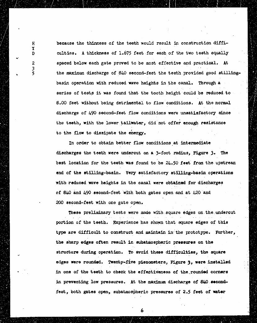
D culties. A thickness of 1.675 fee t for each of the two tee th equally .- 2 spaced below each gate proved t o be most efji'ective and practical. A t 3
b 5 the maximum discharge of 840 second-feet the tee th provided good s t i l l ing-
basin operaticx~ with reduced wave heights I n t h e canal. Through a
ser ies of test,.s it wan found tha t the tooth height could be reduced t o
8.00 feet without being detrimental t o flow conditions. A t the normcll
discharge of 490 second-feet flow conditions were unsatisfactory since
the teeth, with the lower ta i lna tor , d id not off& enough resistance
t o the flow t o dissipate the energy.
In order t o obtain bet ter flow conditions .a t intermediate
discharges the tee th were undercut on a +foot radius, Figure 3. The
best location for the tee th wae found t o be 24.50 f e e t from the upstrean
end of the & W g - b a a i n , Very sat isfactory e t ~ g - b a a i n operatione
with reduced wave heights i n tho canal were obtained fo r discharges
of 8k0 &d 490 second-feet with both gates open .and a t 420 and
280 second-feet with one gate open.
These preliminary t e s t s were made with square 6dies on the undercut
portion of the teeth. Btgerience has shown tha t 7square edges of this
type a re d i f f i cu l t t o construct and maintain i n the prototype. Further,
the e b r p edges often resul t i n subatmoepheric pror8ur.s on t h e
structure during operation. To avoid theee difficulties, the requare
eiiges were rounded, Twsnty-firre p iezaatera , -re 3, were ins ta l l ed
j.n one of the t ee th t o check the effectiveness of the.rounded corners
in prwenting low pressures. A t the maximum discharge of 8l4 second-
fee t , both gates open, subatmospheric p r e s m e s of 2.5 fee t of rater

D showed grea te r than atmospheric pressures. With 4.20 second-feet dis-
2 charging through one gate, subatmospheric pressures between 0.7 and '2 I
5 2.4 f ee t of wa'ter prototype were observed on piezometers 2, 7, and 10.
A t normal discharge o f 490 second-feet with both gates open, all pree-
sures were above atmospheric. The piezometer pressures a re shown i n
Table I in tabu la r form. The observed pressures could probably be
increased by fur ther rounding the edges on t h e undercut portion of t h e
t ee th but this would a l so lleduce t h e i r efficiency as energy dissipa-
t o r s . Considering the infrequency of operation with f u l l gate openings
and t h e small magnitude of t he subatmospheric pressures, t h e a b ~ v e
tooth design, Figure 3, i s recommended.

F?WSURES IN FEET OF WATER ON RECOMAQXDED !EETH*
2, Gates 1 . 2 M t e s 1 1 Gate
% Pressure in feet of water prototype at the piezomster. w Minus(-) indicates that the pressure ia subatmospheric. W Pressure is greater than 10.0 feet of water prototype.
Piezometer locations are shown i n Figure 3.

The or ig ina l design of the center p ie r I n t h e eti l l ing-basin -'
2 i s shown i n Figure 1. The t o p i s a t elevation 3168. Model t e e t ~ 3 5 *wed t ha t t he t o y elevation of the p i e r could be lowered 3 f e e t t o
elevation 3165 with very minor changes i n flow conditions. With t h i s
lower elevation and with t h e mxhum discharge of 840 second-feet, t h e
wstersurface i n t he st i l l ing-baain was 0.5 f ee t above the t o p of t h e
pier. A t lower discharges the watersurface was always below the t o p
of the pier. Any reduction i n t h e length of t h e p i e r increased t h e
wave heights i n t he canal. The recommended p ie r i s the same Length as
t he or iginal , with t he top lowered 3 f ee t t o elevation 3165, Figure 2.
Transition .Studies
In the or ig ina l design, Figures 1 and 6, v e r t i c a l wing-walls,
25 f ee t long, conducted the flow fram the s t i l l ing-basin t o t h e canal
causing eddies and objectionable waves t o form i n the canalo The wing-
w a l l s were mplaced with a 25-foot long, gradually-changing t rans i t ion ,
Figure 2. This t r ans i t i on car r ied the water fram the stilling-berein
t o t he canal with a minimum of disturbance. A aecond t rans i t ion ,
50 feet long and following the ganeral Unea of t h e f i r a t t rans i t ion ,
did not improve flow conditions. Therefore, the 25-foot long, r
gradually-changing t r a n s i t ion i s recommended.
,$anal Studies
In the o r ig ina l canal design t he r ip rap extended beyond t h e
t r ans i t i on f o r 40 feet, ,Figures 1 and 6. The r ip rap section i n t h e
o r ig ina l model was paved with concrete with t h e remainder of t he cana l

wave action along the banks of the canal. To more nearly represent
conditions tha t would obtain i n t he prototype t h e concrete paving was
replaced in the model with rock, scaled down from t h e expected
prototype s ize of dumped riprap. The rough surface of t he dumped
r iprap tended t o absorb the waves and reduced the wave heights i n t h e
canal. The model s tud ies indicated t h e need fo r a minimum length of
40 f ee t of dumped r ip rap i n the canal below the t rans i t ion .
Recommended Design
The recommended design of t he Angoscura Canal ou t le t works
includes the U . 0 e f o o t width of s t i l l ing-basin with t he sloping
f loor , four undercut t ee th and the revised center a e r . The revised
t r ans i t i on and 40 f e e t of dumped r iprap in the canal a r e included.
This recommended design is shorn; I n Figures 2 =d 9B. Detai ls of t h e \
undercut t ee th a re shown b Figure 3. Ehergy d i s e i p t i o n i n t h e
s t i l l ing-basin was sa t i s fac tory f o r a l l discharges with both one and
two gates opan, I n no case did waves or surges ovestop t h e s t i l l i ng -
basin walls. The t r ans i t i on conducted the flow smoothly from t h e
s t i l l ing-basin i n t o the canal. The dumped r iprap below the t rans i t ion
protected the canal against scour and because of i t s rough surface
helped t o reduce wave heights along the canal banks fa r ther downstream.
The s t i l l ing-basin center wall i s at elevation 3165.0, t he s ide
walls a r e at elevation 3170.0, w h i l e the t o p of the canal banks a r e a t
elevation 3168.5. Figure 10 shows model operation at the maximum dis-
charge of $40 second-feet with both gates open. The canal watersurface
i s at elevation 3167.8. The dormstream end of the center w a l l i s

L D Figure ll shows model operation a t t h e normal discharge of 490 second-
2 fee t with both gates open. he canal watersurface i s at elevation 3165.4. 3 5 Figure I2 shows model operation a t a discharge of 420 second-feet .
through one gate . The canal wateraurface i s at elevation 364.8. .
Figure 9 A shows one gate discharging 200 second-feet with t h e canal
watersurface a t elevation 3162.8.
Table 2 shows wave heights for t h e recommended design as
measured a t four locations on the center l ine of the canal f o r discharges
of 840 and 490 second-feet with both gates open and for 420 second-feet
with one gate open.
\WE HEIGHTS I N PROTOTYPE. F l E C
Location of Stations - On canal centerl ine
Stat ion 1- end of s t i l l ing-basin - 0 fee t Stat ion 2 - end of t ransi t ior l - 25 fee t Stat ion 3 - end of dumped r ip rap - 65 fee t S ta t ion 4 - end of model - ' 105 feet


.Vn..u a* I.CLAY.rIOY
N t O S O U I I # A S I N C I O J C O I 4 1 1 0 0 S r U m 4 u u t r - a o u r w 0 A l O t .
ANOOSTURA DAM


FIGURE 7
A . Low Surge 840 Sec on&- f eet Both Gates Open
B. High Surge 840 Second-f ee t Both Gates Open
ANGOST'URA OlJTLET WORKS 1 :12 SCALE MODEL ORIGINAL IZSIGN

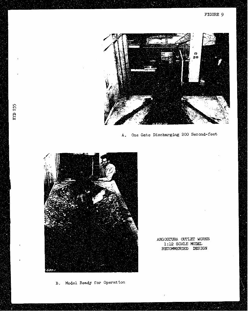
A. One Gate Diecharging 200 Second-feet
ANGOSTUEU OUTLEX' WORKS 1:12 SCALE MODEL
RECOMMENDEI) DESIGN
B. Model Ready fo r Operation

Maximum Discharge 840 Second-f e e t Both G a t ea Open
A N C O S m OUTLET WORXS 1 :12 SCALE MODEL RECOMMENDED DESIGN

FIGURE 11
Normal Dl scharge 490 Second-f eet Both Gates Open
ANGOSTURA 9 m m WORKS 1 :12 SCALE l4OIZEL RECOMMENDED DESIGN

FIGURE 12
Maximum Dl ac harge 420 Second-f eet One Gate Open
ANGOSTURA OUTLET WORKS 1 :12 SCALE MOREL RECOMMENIED DESIGN