forewordcarpiserve.com/pdf/lb100opsmanual.pdf · foreword - thank you for selecting coldelite to...
TRANSCRIPT


F O R E W O R D
- Thank you fo r selecting COLDELITE t o m e e t today's f as t growing demands. Your COLDELITE f reezer has been manufactured a t one o f t h e most modern f reezer manufacturing plants in t h e U.S.A., o u r Winston-Salem, North Carolina facility, utilizing t h e most advanced equipment and technology available in t h e industry. We a t COLDELITE, t ake g r e a t pride and c a r e in t h e manufacture o f e a c h and every f reezer , using only the f ines t components available, t o provide you with years o f trouble-free operation.
Over twenty-five years o f exper ience in t h e manufacturing o f dispensing equipment have guided us in the p r e - j a r a t i ~ n o f this Operation and Service Manual. PLEASE READ IT CAREFULLY. Keep it f o r fu ture re fe rence and most o f all, follow t h e instructions f r o m t h e very t ime your machine is put into service.
On t h e following pages, you will find important information and pro- cedures which describe t h e proper installation, sanitizing, operation, and maintenance o f your COLDELITE machine. W e feel cer ta in t h a t your full compliance with these instructions will assure you of ex- cel lent performance, trouble-free operation and a profi table business f o r years t o come.
PACE A-1

INDEX
P A R T 1
P A R T I 1
P A R T I11
P A R T IV
P A R T V
P A R T VI
P A R T VII
P A R T VII I
P A R T I X
........................ INSTALLATION - 1
......................... A) U N C R A T I N G 1 ............. 8 ) POSITIONING T i f E MACHINE .I ............ C) E L E C T R I C A L REQUIREMENTS Z ............. D l E L E C T R I C A L CONNECTIONS 3
......... E l COMPLETING THE INSTALLATION 4
E X P L A I N A T I O N OF CONTROLS. ............. 4 A) T H E SELECTOR SWITCH ................. 4 8) T H E M E C H A N I C A L TIMER .............. -6
................ C l T H E DISPENSE HANDLE 6 ............... D l T H E ELECTRICAL PANEL 6
E l OTHER CONTROLS ................... - 8
I N I T I A L CLEANING PROCEDURE ............. 8
.............. ASSE:VBLINC THE FREEZER -10 .............. A) ASSEMBLING THE aEATER 1 1 ........ 8) XSSEiL1BLING THE DISPENSE HEAD 11
................ SANITIZING T i f E FREEZER -12
.................. STARTING THE FREEZER 1 3
................ OPERATING THE FREEZER 17
T E C H N I C A L INFORMATION ................ 15 ...................... A) REFRIGERATION 15 ...................... 8 ) BEATER MOTOR 15 ....................... C) DRIVE SYSTEM 16
......................... M A I N T E N A N C E 1 6 ............ A] TROUBLE SHOOTING GUIDE - 1 8
81 PARTS INDENTIFICATION ............... 20 ................... C) 'NIRINC SCHEMATIC 24

IMPORTANT
Failure t o closely follow set-up, operational and maintenance procedures may result in damage t o the unit and/or void your warranty. Coldelite Corporation will not be responsible for any machine not properly main- tained.
In t h e event this unit should malfunction, please contact your Coldelite Distributor or authorized service agency.
PART 1 INSTALLATI0 N
Before starting this procedure, make certain the shipping case does not show any evidence of having been dropped, tampered with or abused in such a way as t o indicate that its contents may have been damaged in transit.
IMPORTANT: Should t he outside of the shipping case give any indication o f possible hidden damage, s ta te this on the bill of lading before signing. Contac t the carr ier immediately and request an inspection of t he damage. If this procedure is not adhered to, you will forfeit your right t o file a damage claim and be responsible for subsequent repair costs.
A) UNCRATINC
Proceed as follows:
1. Remove tho machine from its carton and remove all protective crating material.
2. Remove the single screw a t the bottom of each side panel, Remove t h e side panels by pulling in a downward and outward direction, allowing t h e panel to slide free, The protective plastic coating which is laminated t o t h e panels czn now be removed by simply peeling off.
8) POSITIONING THE MACHINE
1. The machine is now ready to be positioned onto your counter. The counter must b e capable of supporting 225 Ibs., and should be vibration free, Rein- force it if necessary. Remember, when choosing a location, your unit is a i r cooled, proper air flow wi l l need t o be maintained. Allow a t least six (6) inches on ei ther side and a minimum of twelve (1 2 ) inches between the r ea r of the machine and any obstruction. (Ref. Fig, 1 )
PACE 1

17: Flow
I I I
Side View La-1 00B Front View LB-1008
FIGURE 1
Clearances Required For
Proper A i r Cooling
NOTE: If these clearances are not maintained, tile production capacity w i l l be reduced, cycling wi l l increase and the potential exists that the
" - machine w i l l stop immediately.
2, The machine should be within four feet o f the power supply outlet,
3- Position the machine for easy accessibility when cleaning, servicing and performing routine maintenance,
4- 2osit ion the machine away from direct sunlight. f o r every 2 O F above 68 F, the mschine's performance w i l l decrease by approximately 1 %-
5- Once the machine is set in position, it should be le?re!ed as accurately as possible-
C) ELECTRICAL REQUIREMENTS
A11 w i r i n g installed to operate this freezer must be in accordtnce \vith the National Electr ical Code and/or local e1ec;rical codes, rules and regulations. The machine must be properly grounded. It is recommended the power supply be installed by a licensed electrician.
VOLTAGE LB-1008: 1 15 Volts
RUNNING AMPERAGE FLA: 27.0
FUSE SIZE: 32 A M P ~Uax.
WIRE SIZE: (50 Fi. 1tlax.1 $10
POWER SUPPLY must 5e adequate to meet requirements at al l times, V 0 1 i ~ c e f!uc;uations, with ihe machice in operation, should nor exczed = 1 O ~ ~ O F the normal or rated voltace-
PACE 2

f ie mode1 LB-1008 requires a 11 5 Volt, 60 Hertz dedicated circuit [ no other electrical appliances on the circuit), X separate circuit breaker ra ted at 30 AMPS is required . .
. - ADEQUATE WIRING must be provided with respect to wire size or gauge. This includes the direct power line to the madnine electrical and connection box, Coldelite batch Creezers are equipped *:4ith proteciion for the beater motor. Should the l ine voltage crop, or in :he unIikely event a shori circuit occcrs, the overioad protector w i l l automatically disconnect :he contactor. This wiII stop :he machine immediately so that no permanent damage w i l l be caused to the motor.
To resiart the freezer, depress the reset button which is accessible t h r o u ~ h an opwing at the lower right cornlr of the risnt sic2 panel. The protector must cool for several minutes before the reset wil l operate (Ref. Fig. 2).
The compressor is internally protected- If the Xlixon proteGor trips due to an overload condition, the compressor wil! stop and auionaiicalIy restzf l once ihe protector has cooled for several minutes.
01 ELECTRICAL CONNECTIONS (REF. FIG. 51,
H a v i q removed ;he riskit side ?ace!, i h ~ machine's t!ec;rica[ cornponencl wir ins c3nnec:ion box c t n be located az the lower righr corner. ?=move the itleca-ical connection Sox cover.
-. I ne ?owe? !ine i s f irst ,passed :hroush zhs ac<=si hole iocactd a< the bot tom r ight :oar o f the machine. The tine is ?ken ~assed upward thrcugh t k t S C C ~ ~ S
hole in the 3ol?om dack z'ir=c!:/ i x o :he c!ec;rical c3r,nec;ion box, The power iins ,nay now be cannec;td ;O i=rminab L i and LZ. Us2 aaproprizce e lec~r i ca l wiring hardware and cocneciors as governed 5y e l e ~ r i c a l codes.
In al l installations, the machine MUST be properly grounded. Adequate ground continuity is assured by runnjng and securely fastening a ground line (conductor) to the ground lug located in :he electrical connection box,
UTTO

El COMPLETING THE INSTALLATION
Sanitary regulations may require that the counter model machine be sealed t o t h e counter top. To seal, proceed as follows:
1, Clean the counter top thorougidy to remove any dirt, dust, e tc .
2, Clean the lower rim, or bottom flange of the machine base (Ref. Fig. 31.
3. Apply a bead (approx. 114" wide) of General Electric RTV- 102 silicone sealnat (or equivalent) to the bottom surface o f t he base.
4, Place t he machine on the counter in the location chosen,
5. Remove any excess sealant by slowly running a f la t edged tool (spackling tool) .around the flange of the base frame. This will c r ea t e asearnless joint between t h e frame and t h e counter top (Ref. Fig. 3).
6. Allow sealant t o dry thoroughly (refer t o sealant manufacturer's directions) before operating the machine.
FIGURE 3
SILICONE SEALANT
PART I I EXPLANATION OF CONTROLS
All operator controls a r e conveniently located a t the front of the machine. (Ref. Fig. 4).
A) THE SELECTOR SWITCH
The selector switch is a four position, four function switch. The positions of t he switch (Ref. Fig. $1 along with respective functions a re as follows:
1, O F F - The machine does not operate in this position.
PACE 4


2- PRODUCTION - This position is used t o f reeze t h e mix ingredients t o a finished product, Both compressor and bea te r a r e in operation,
3, EXTRACTION - This position is used for dispensing of frozen, finished product. The b e a t e r is in operat ion and t h e compressor is inactivated,
4, CLEAN - This position is used f o r cleaning and sanitizing procedures. Only t h e b e a t e r motor is ac t iva ted in this mode. All refrigeration c i rcui ts a r e de-energized.
8 ) MECHANICAL TIMER (Ref. Fig. 41
The mechanical t imer is a device f o r se t t ing t h e minutes required t o produce a ba tch o f finished product. At t h e end of the f reeze cyc le
- t h e t i m e r will signal and audible reminding t h e operator t h e production cycle, finished product, is completed. The t imer is a reminder only and does not turn o f f t h e machine. The t imer will be discussed in deta i l in Par t VI, S tar t ing The Machine.
C) DISPENSE HANDLE (Ref- Fig. 4)
Moving t h e dispense handle in an upward direction raises t h e g a t e cover for dispensing finished product. A downward motion closes t h e gate,
I FIGURE 5
PACE 6
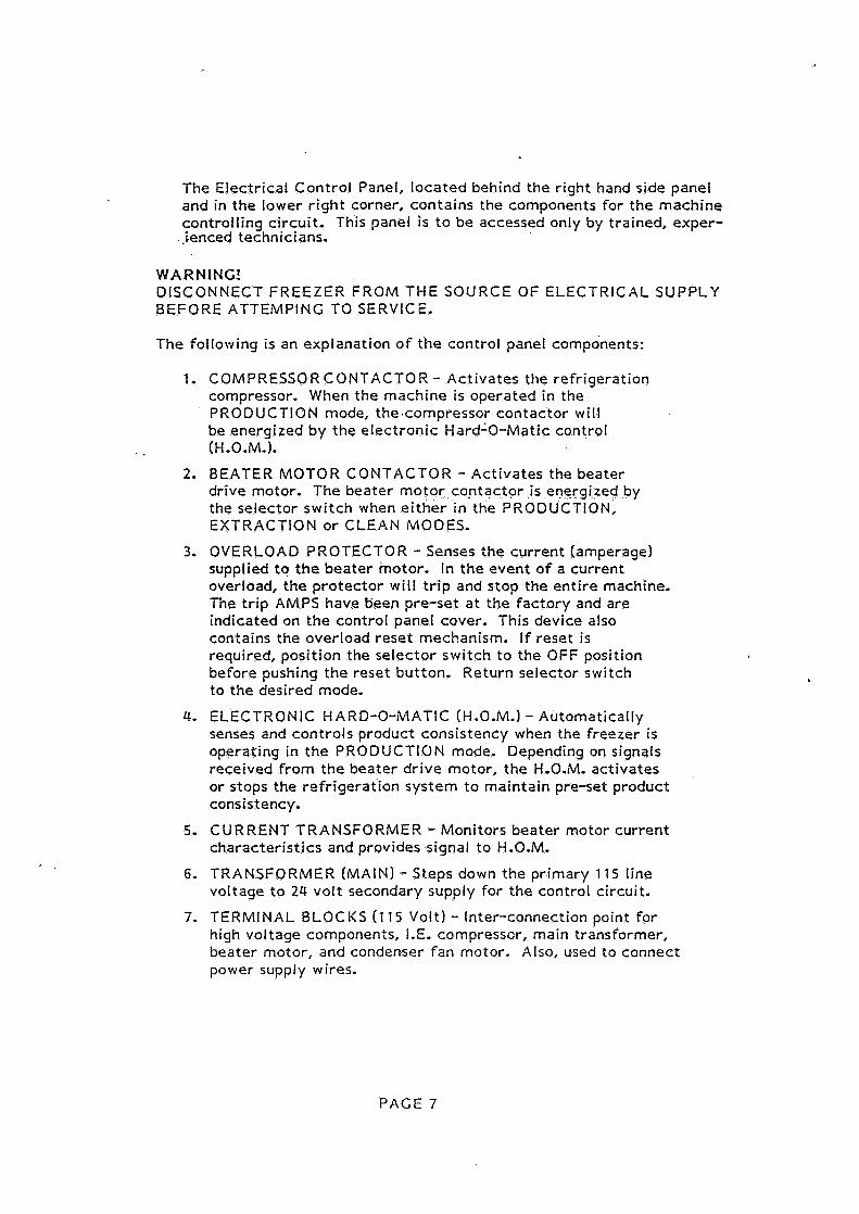
The Electrical Control Panel, located behind t h e right hand side panel and in t h e lower r ight corner, conta ins the components for t h e machine controlling circuit. This panel is t o b e accessed only by trained, exper-
..ienced technicians.
WARNING! DISCONNECT FREEZER FROM THE SOURCE OF ELECTRICAL SUPPLY BEFORE ATTEMPINC TO SERVICE.
The following is a n explanation o f t h e control panel components:
C OMPRESSO R C ONTACTO R - Activates the refrigeration compressor. When the machine is operated in the PRODUCTION mode, the.compressor contactor will be energized by t h e e lect ronic Hard'O-Ma t i c control (H.O.M.).
BEATER MOTOR CONTACTOR - Activates t h e beater drive motor. The beater motor -con tac to r is energized by t h e se lector switch when e i t h e r in the PRODUCTION, EXTRACTION o r CLEAN MODES.
OVERLOAD PROTECTOR - Senses t h e current (amperage) supplied t o t h e bea te r motor. In t h e event of a current overload, t h e protector will t r ip and s top the en t i re machine, The tr ip AMPS have been pre-set a t t h e factory and a r e indicated on t h e control panel cover. This device also contains t h e overload rese t mechanism. If reset is required, position the se lector switch t o t h e OFF position before pushing t h e reset button. Return selector switch to t h e desired mode.
ELECTRONIC HARD-0-MATIC (H.O.M.) - Automatically senses and controls product consistency when the f reezer is operaring in t h e PRODUCTION mode. Depending on signals received from t h e beater drive motor, t h e H.0.M. act ivates or stops the refrigeration system t o maintain pre-set product consistency.
CURRENT TRANSFORMER - Monitors bea te r motor current characterist ics and provides signal t o H.0.M.
TRANSFORMER (MAIN) - Steps down t h e primary 115 line voltage t o 24 volt secondary supply for the control circuit.
TERMINAL BLOCKS (1 15 Volt) - Inter-connection point for high voltage components, I.E. compressor, main transformer, beater motor, and condenser fan motor. Also, used to connect power supply wires.
PACE 7

8 6 9 TERMINAL BLOCKS (24 Volt) - Serves as the in twconnect ion point for all 24 volt controlling c i rcui t components,
El OTHER CONTROLS
1. HIGH PRESSURE CUT-OUT CONTROL - Located on t h e r ight side of t h e freezer's upper lef t corner, and is installed into t h e compressor discharge line (high pressure side). In the event o f a high pressure condition, it will shut down t h e compressor. Reset is a u t o m a t i c when t h e high pressure subsides. A common cause for cut-out is r es t r i c ted air flow through the condenser coil,
2. SAFETY SWITCH DISPENSE HEAD - ' The switch is located behind t h e f ront panel and is a normally open switching device t h a t is mech- anically act ivated t o t h e closed position when t h e dispense head is securely closed and la tched with the retaining knob. Should an a t t e m p t be made t o open t h e dispense head during f r e e z e r operation, t h e switch automatically opens de-energizing t h e machine.
PART I11 INITIAL CLEANING PROCEDURE
The new machine must be completely disassembled, washed, and sanit ized pr ior t o starting. Proceed as follows:
1. Remove t h e i tems packaged with the freezer, (spare pa r t s o r s t a r t - up kit, sample sanitizer, and sani tary lubricant).
THE SPARE PARTS OR START UP KIT will include; a complete s e t o f replacement o-rings and rubber seals, o-ring ex t rac to r , cleaning brush, a tube of sani tary lubricant, four sample packages o f sanitizer, a spatula, and t h e Cperation and Service Manual,
HELPFUL SUGGESTION: Before proceeding with the disassembly o f t h e f reezer , it is recommended t h a t a plast ic dish pan be used in which t o place t h e parts. This will minimize t h e possibility o f misplacing o r damaging t h e various compon- e n t parts.
2: Proceed with the disassembly by removing the dispense head (Ref. Fig. 61.
PACE 8

Grasp and pull the retaining knob outward. Rotate the knob clockwise one. quar te r tu rn t o unlatch t h e dispense hezd.
Swing t h e dispense ?lead open and lift upward removing it from t h e hinge pin.
3. Further disassemble the dispense head by removing t h e fill cover retaining rod and t h e plastic fill cover.
To remove t h e dispense handle and g a t e cover, carefully unscrew t h e dispense handle pivot knob a t t h e lef t and slowly pull t h e handle forward releasing t h e handle, tension spring and g a t e cover.
4. Remove the bea te r from t h e f reezer cylinder with a s t ra ight and forward pull. Slide ihe rubber beater shaf t (lip) seal o f f of t h e bea te r shaft.
5. Using the O-RING EXTRACTOR, remove t h e large o-ring f rom the back of t h e dispense head, and t h e g a t e cover o-ring,
6. The machine is now completely disassembled. The par t s wi l l be washed, rinsed and sanitized- (Ref. Fig. 71,
PACE 9
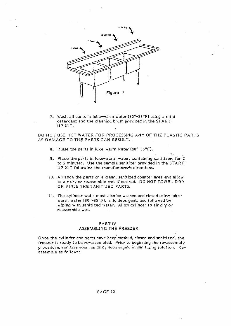
7. Wash all parts in luke-warm water (80°-8S°F) using a mild detergent and the cleaning brush provided in the START- UP KIT.
DO NOT USE HOT WATER FOR PROCESSING A N Y OF THE PLASTIC PARTS AS DAMAGE TO THE PARTS CAN RESULT.
Rinse the parts in luke-warm water (80°-ilS°F).
Place the parts in luke-warm water, containing sanitizer, for 2 t o 5 minutes. Use the sample sanitizer provided in the STXRT- UP i< IT following the manufacturer's directions.
Arrange the parts on a clean, sanitized counter area and allow to air dry or reassemble wet if desired. DO NOT T,'3WEL D R Y OR RINSE THE SANITIZED PARTS.
The cylinder walls musi also be washed and rinsed using luke- warm water (80°-8S°F), mild detergent, and followed by wiping with sanitized water. Allow cylinder to air dry or reassemble wet.
P A R T IV ASSEMBLING THE FREEZER
Once the cylinder and parts have been washed, rinsed and sanitized, the f reezer is ready to be re-assembled. Prior to beginning the re-assembly procedure, sanitize your hands by submerqing in sanitizing solution. Re- assemble as follows:
PACE 10

A) ASSEMBLING THE BEATER
1. Lubricate and install the BEATER LIP SEAL. Using the sample sanitary lubricant included in t he START- UP KIT, lightly coa t the front and back surfaces of t he seal and slide t he seal onto the beater shaft.
2, Insert the BEATER into the freezing cylinder. Hold the beater horizontal and slide i t into the cylinder until it will go no further. Be sure the BEATER LIP SEAL is in place,
. 3. Rotate t he BEATER until you feel the drive shaft engage and push the bea te r further toward the rear t o properly seat.
B) ASSEMBLING THE DISPENSE HEAD (Ref, Fig. 61.
1. Begin by gathering all of the parts required t o assemble the DISPENSE HEAD. These parts include: one (1) dispense head o-ring, dispense head, fill cover, fill cover retaining rod,
gate. cover, ga t e cover O-ring, tension spring, dispense handle and retaining knob.
2. Install the o-ring into the gate cover o-ring groove. Lightly lubricate the o-ring with sanitary lubricant for f ree move- ment of the ga t e cover during dispensing.
3, Position the tension spring between the handle and ga t e cover recess and remount the handle onto the pivot stud. Install the white plastic retaining knob.
4. Re-attach the fill cover t o the fill chute by inserting its retaining rod.
5, Install the dispense head o-ring into the o-ring groove located on the back side of the head, Lubricate the o-ring with a light coating of sanitary lubricant.
6, Attach the DISPENSE HEAD to the freezer by guiding t h e head pivot onto the hinge pin.
7. Close the dispense head and latch into place with the retaining knob.
The machine is now completely assembled and ready to be sanitized.
PACE 11

PART V SANITIZING THE FREEZER
Prior t o starting the freezer with the product t ha t will be served, t h e f reezer mus t be sanitized-
Sanitizing t h e freezer is most important as the procedure retards t he growth o f bacter ia and insures acceptable product test results when examined by local Heal th and/or Agriculture Departments.
The frequency of cleaning and sanitizing cycles must comply with local Health Regulations. If uncertain about the regulations in your area, contact the local Board of Health or Department of Agriculture.
To begin the sanitizing process, you wi l l need a clean pail, wire wisk, and a so f t plastic bristle brush.
1. Mix 2 9z. of sanitizer, STERA S H E E N 'GREEN LABEL O R EQUIVALENT, (sample packs included in the STXRT- UP KIT) into a pail containing one gallon of warm water. Dissolve sanitizer by stirring with a wire wisk, This formula will make a 200 P.P.M- (parts per million) concentration of chlorine sanitizing solution.
IMPORTANT: Do not exceed the formula recommended by the sanitizer manufacturer as i t wi l l not add to its effectiveness,
2. L i f t t h e fill chute cover and pour the sanitizing solution into the cylinder until t he solution rises in the fill chute.
3. Turn the selector switch to the CLEAN position for 30 seconds (Ref, Fig. 4, PC. 5 ) . The beater will run allowing the sanitizing solution to come in contact with all internal product contact areas- During ihe 30 second CLEAN period, the remainder of the one gallon of sanit- izing solution should be added filling the fill chute,
4. Turn the selector t o ihe OFF position.
5. Using a sanitized soft Srisile brush, brush the dispense chute, the underside of the fill cnute cover, and the sides of the fill chute that w i l l come in contact with product. Close the fill cover. Allow the sanitizing solution to remain in contact with the product areas for three ( 3 ) to five ( 5 ) minutes-

6. Place a c lean pail under the dispense chu te and slowly raise t h e dispense handle and g a t e cover t o dra in the sanitizing solution from t h e cylinder.
7, Allow the sani t izer t o drain completely, CIose the dispense handle,
HELPFUL SUGGESTION: When the sanitizer has stopped flowing f rom t h e dispense head, leave the dispense handle in the OPEN position znd tu rn t h e se lec to r switch t o t h e CLEAN position for two t o i h r e e seconds to assist in removal of the last b i t of sanitizer.
00 NOT RINSE THE idACHINE WITH FRESH WATER AFTER THE SANITIZING .PROCESS HAS BEEN COltlPLETEO AS THIS ACTION WOULD COIUPLETELY NEGATE THE ENTIRE PROCESS.
CAUTION: It is recommended t h a t the beater b e turned a s little as possible during the washing and sanitizing processes as excessive ro ta t ion c a n result in premature wear of bea te r blade surfaces;
PART V1 STARTING THE FREEZER.
Only a f t e r t h e machine has been thoroughly cleaned and sani t ized is the r'reozer ready f o r production o f the.initia1 batch,
You have t h e finest, fas tes t and most depenazble f reeze r nanufac:ured, Congratulations!. You a r e now re,ady t o make hard ice c ream, sherbets, ic-ts, g e l a t o and more, .
r
A successful1 re ta i l business depends entirely on the quali ty of t h e product it produces, Therefore you a r e urged t o choose wisely only quali ty increaients f o r t h e formulation or' your f rozen products- Please remember , inexpensive and inferior ingredients will result in a similar inferior product and a d i s a t i s f e d customer.
Please observe the Following recommendations:
1. Make your mixes from- hi& quality natural products o r obxain from a reliable and trust;vor;hy supplier.
2- 00 not serve the product :o the customer unless i ts quali:y and appearance 2r2 entirely sacisfac:ory.
3. 8e sure the machine is kept clean a t all times.
4. In t h e event t h e f r e e z e r requires service, always con tac t an authorized COLD ELITE Technician,
8 a t c h sizes will vary depending on the mix ingredients, desired overrun, etc,, Experience will be t h e t eacher for judging the desired size of each batch- F o r example, when making ices, a larger quantity o f mix may be poured into t h e cylinder as the final finished ba tch wi l l have less expansion due t o minimum overrun.
The initial quanti ty o f mix t o be.poured into t h e cylinder is a minimum or' 1.7 quar t s (54 oz,) and 2.2 quar ts 170 oz.1 maximum, As a guide, when charging t h e cylinder with mix, t h e horizontal mix level mark on the dispense head will indicate a fill of 1.9 quarts 160 oz.).
P repare 1.7 t o 2.2 quar ts of liquid mix, approximately 38O t o 42OF, in a clean, 'sanit ized measuring container.
PART VI1
OPERATING THE FREEZER
1. Pour t h e mix into t h e fill chute and close the chute cover.
2. Set t h e t imer t o 10 minutes and the se lector switch t o PROOUCTION. [Ref. Fig. 4, Pg. 5) .
3. Allow the machine t o f reeze the product t o the desired consisiancy.The t imer may produce an audible prior t o o r a f t e r t h e completion o f t h e freeze cycle. The 10 m i n $ ~ t e t imer se t t ing is an average. Exact timing must be arrived a t based on the mix used, desired overrun and firmness, and t h e consistancy control setting t o be discrrssed in PAST V l l l TECHNICAL INFORMATION.
4. On t h e initial batch when t h e timer sounds a t 10 minutes, turn t h e se lector switch t o EXTRACTION. lift the dispense handle and draw t h e finished batch from the cylinder into a sanitized, cold container. After dispensing is complete re turn the sa lector switch t o OFF.
Note tha t the second batch will be made in a lesser time. Again, exac t t iming must b e concluded based on t h e desired finished produc-i characteristics.
When working with different flavors, plan the saquence of batches before hand, Example, always s t a r t with vanilla, possibly cherry vanilla, vanilla chip, followed by coffee, walnut o r o ther light colored flavors. Naturally, chocolate would b e the final flavor dispensed.
PACE 14

Always remember t o use quali ty ingredients. Producing quali ty i c e creams, ices o r sherbe t s will guarantee a superior product and a happy customer.
PART V111
TECHNICAL INFORMATION
A) REFRlCERATION
Compressor: Hermetic, -75 H.P., R4C4 Refrigerant Voltage: 115 Volt, Single Phase, 60 Her tz FLA: Ampergae = 2 3 Suction Pressure: 1 8 PSI Discharge (Head) Pressure: 255 PSI CooIing System: Air Refr igerant Charge: 20 0gCB
B) BEATER MOTOR
Voltage: 115 Volt, Single Phase, 60 Hertz, 314 H.P. H.0.M: Cut-out Amperage 7-6 Overload Cut-out Amperage 8,s
1 ) Adjusting Patch. Temperature
The LB-1008 uses a Hard-0-Matic sys tem which is r e fe r red t o as H.0.M-. This e lect ronic device controls the refr igera t ion system for t h e freezing cyl inder by 'sensing' t h e consistency o r hardness of t h e product inside t h e f reezing cylinder. No the rmos ta t s a r e used with this-system.
T h e firmness o f the batch product will depend on the se t t ing o f the H.O.M. e lec t ron ic control-
The compressor must c u t o f f when t h e current, absorbed by t h e bea te r motor, r eaches the amperage indicated on t h e label in the e lect r ica l control box (H.O.M. Cut-out AMPS). By using an a m m e t e r and clamping around one leg o f t h e power line feeding t h e b e a t e r motor, i t is possible t o r e a d t h e amperage d rawn by t h e motor. Factory s e t cut -out is f ,, 6 .MPS.
PACE 15

2 ) Electronic Hard-0-Matic Control Adjustment ( A 5 OF ~ E R I ~ L NuNBZQ ~ 8 3 3 )
SETTING PROCEDURE
The HOM board includes 3 potentiometers PT1, PT2 and PT3,2 pilot lights (LED), one red and one green, and 8 DIP SWITCHES (see FIG.1).
PT3
\ P:'. \ RED PILOT LIGHT
DIP-S uOk'Ttt rt- I GREEN PILOT LIGHT (LED)
MICROPROCESSOR
( Fig. 1 )

In order to set the HOM board, you must first coniigure the DIP SWITCHES according to the type of machine. See the table below.
1) Check the Dip switch position (see table 1).
2) Fill the cylinder with liquid mix and turn the main selector switch to the PRODUCTION mode.
3) Connect a clamp tester on a phase of the beater motor to read the current.
MACHINE
LAB lOO/B
4) Set the machine in Production.
DIP
Voltage & Phase
115/60/1
1 2 3 4 5 6 7 8
- PT1 Setting : Don't move it. Its position has no effect.
- PT3 set tin^ : Turn 20 turns clockwise
- PT2 Setting : It's the main setting of the HOM board; turning clockwise increases the current when the compressor cuts off. When the current of the beater motor reaches a value near the name plate value, turn the PT2 trimmer'anticlockwise until the red led shuts off and the green led lights on. Turn PT2 slowlv anticlockwise until the compressor stops once vou reached the 100% of the Beater motor name plate current.
OFF OFF
P.S.: If the compressor motor never stops it's necessary to make 2 turns through the current transformer
OFF OFF
PAGE 16.
OFF OFF ON OFF

C ) DRIVE S Y S T E M The ro ta t ion o f the beater i s counter clockwisz and is motivated by a be l t d r i ve system,
P A R T IX
MAINTENANCE
Your COLDELITE machine has been designed, engineered and manufactured t o achieve high performance and long durability.
The l i fe expectancy o f a machine, any machine, does not depend only on the qua l i t y o f i t s components and design, but also on the beneficial e f f e c ~ s o f basic procedures.
I t is important to you, therefore, to become famil iar with a k w o f these basic procedures:
. . " t - .. --:.-:, % ?:>'-* ,. h .:.-.v.*-: J.. -- ..,. ; . - . - 3
Remove '0' rings only w i t h the '0' r ing extractor supplied wlth the machine.
Clean the machine according to the instructions,+ . = - . G,-s.,r. . .. - -:_ - = _ -
Lubricate al l '0' rings and seals, as instructed,
The wearing or the improper cleaning o f the beater shaft seal, w i l l resul t in leakage from the rear- Check the dr ip t ray frequently and replace the seal when necessary.
Replace any '0' r ing that has a nick in it, If not replaced, it wi l l leak and in ter fere with the proper performance o f the machine.
When all the spare parts supplied with the machine are used, re-order immediately. Do not wait unt i l the part is required again-
NEVER use the AUTO position for washing, sanitizing and in i t ia l ly f i l l i ng the freezing cylinder.
IMPORTANT - During the washing and sanitizing period, run the machine only for t ime st r ic t ly necessary for this operation. Prolonged use o f the beater in the Cleaning position may causcl severe damage to the machine.
Always wash metal, plastic or rubber parts in lukewarm water. NEVER, NEVER USE HOT VJATEil!
I M P O R T A N T As the model LB-1008 i s an air cooled machine, i t s eff ic iency depends on the a i r cooled condenser. The fins of the condenser must be cleaned every t w o o r three months to assure efficiency.
W A R N I N G .-
Ext reme care must be taken when removing side, rear or control box panels.
Always turn the Se1ec;or Switch ro the OFF position. Also, turn o f f the Disconnect Switch on ihe eleca-iczl supply l ine before exposing any e lec t r i ca l connections and/or moving parts, such as belts, pulleys, fan blades and beater.
PAGE 17

TROUBLE SHOOTING GUIDE
PROBLEM POSSIBLE CAUSE SUGGESTED REMEDY
1) Machine will not s t a r t a ) No power t o t h e machine a ) Check c i rcui t breaker, se lector swi tch position, and power supply wiring
b) Off on overload b) Wait 5 minutes and push r e s e t bu t ton
c) Malfuncti oning se lector c ) Contac t se rv ice agency switch
d ) Dispense head d l Check if dispense head safety switch not is properly closed and energized if pin is act ivat ing
t h e s a f e t y swi tch located behind t h e front panel
e) Beater motor e l Check if 24 vol t and compressor t ransformer is oper- contactor not at ing properly energized
2) Product t o o sof t a ) H.O.i\/t. control out o f calibration o r malfunctioning
b) machine low on refr igerant
c) Insufficient freezing t i m e
a ) Contac t author ized service agency
bl Contact author ized service agency
C) Increase f reezing t ime
3) Product t o o hard a) Freezing t ime too long a ) Check fo r proper f reeze t i m e and t h e H.O.M. se t t ing
- - - -
4 ) Machine will not f r e e z e a ) Restricted a i r flow
b) Compressor not working
C) System refrigerant low
d) Malfunctioning H.O.M.
e) Malfunctioning cont ac tor
f ) Insufficient power supply
a ) Remove obst ruct ion o r res t r ic t ion
b) Contac t author ized service agency
c) Contac t author ized service agency
d l Contac t author ized service agency
e) Contact author ized service agency
f ) C o n t a c t author ized service agency
PACE 18

5 ) Compressor will not s t a r t
a ) Low line voltage
b) Open starting capacitor. Relay contacts not closing
C) Off on high pressure
a) Check power supply voltage, Determine voltage drop
b) Replace s tar t capacitor. Replace defective relay.
c ) Clean condenser. Refrigerant over-charge.
6) Compressor operates a) Shortage of refrigerant long o r continuously
b) Dirty condenser . . c) Location 'too warm
a] Repair leak and recharge
b) Clean condenser C) Change to cooler
location
7) Burnt rubber a) Product in cylinder .' a) Refer to H.0.M- odor frozen too hard adjustment
b) Drive belt slipping b) Tighten belt
8) Mix dripping from dispense head
a) Damaged or worn O-ring a) Replace suspect o-ring
9) Mix dripping. from side a) Damaged or worn beater a) Replace beater seal overflow drip tray seal
PACE 19