draft ac 150/5300-14c, design of aircraft deicing ...subject: design of aircraft deicing...
TRANSCRIPT

U.S. Department
of Transportation
Federal Aviation
Administration
Advisory Circular
Subject: Design of Aircraft Deicing Facilities Date: DRAFT
Initiated by: AAS-100
AC No: 150/5300-14C
Change:
1. PURPOSE. This advisory circular (AC) provides standards, specifications, and guidance for designing aircraft
deicing facilities.
2. APPLICATION. The FAA recommends the standards and recommendations in this AC for use in the design of
aircraft deicing facilities. In general, use of this AC is not mandatory. The standards and recommendations contained in this
AC may be used by certificated airports to satisfy specific requirements of Title 14 Code of Federal Regulations (CFR) Part
139, Certification of Airports, subparts C (Airport Certification Manual) and D (Operations). Use of this AC is mandatory
for all projects funded with federal grant monies through the Airport Improvement Program (AIP) and/or with revenue from
the Passenger Facility Charges (PFC) Program. See Grant Assurance No. 34, Policies, Standards, and Specifications, and
PFC Assurance No. 9, Standards and Specifications.
3. CANCELLATION. This AC cancels AC 150/5300-14B, Design of Aircraft Deicing Facilities, dated February 5,
2008.
4. PRINCIPAL CHANGES.
a. The term “centralized aircraft deicing facility” now includes “remote aircraft deicing facilities.” The term
“remote deicing facility” was dropped from the definitions (paragraphs1.1 and 1.2 definitions).
b. Clarified that the airport operator’s FAA-approved Snow and Ice Control Plan must be updated to include
non-gate centralized aircraft deicing facilities are a priority 1 facility under AC 150/5200-30, Airport Winter Safety and
Operations. This action enables the facility to remain fully operational during inclement weather; thereby icing conditions
affecting the safety of flight are better managed (paragraph 1-1(a)). For 14 CFR Part 139 certificated airports having
centralized aircraft deicing facilities, the Snow and Ice Control Plan must be revised to reflect that the facility is classified as
a priority 1 area. Compliance with this requirement is 1 year from the issue date of this AC.
c. This edition acknowledges the practice by the aviation industry that a control center (snow desk) building is
a basic component of a centralized aircraft deicing facility (paragraph 2-1(c)).
d. Added new criteria explaining that the centered aircraft deicing pad of a composite grouping of three pads
requires three Vehicle Safety Zones (VSZ) instead of two VSZs. The new VSZ for the centered taxiway centerline will have
a 1-foot gap between the red painted VSZ and the yellow taxiway centerline (paragraph 3-4(c)).
e. Elevated ice detection cameras for infra-red aircraft deicing structures from an option to should. These
cameras allow facility operators to scan airplane surfaces for the presence of frozen contamination before and after airplanes
are exposed to infra-red energy (paragraph 5.9).
Michael J. O’Donnell
Director of Airport Safety and Standards

AC 150/5300-14C DRAFT 5/17/2013
ii
This page intentionally blank.
5/17/2013 AC 150/5300-14C DRAFT
iii
CONTENTS
CHAPTER 1. INTRODUCTION ............................................................................................................................................... 5
1.1 OVERVIEW. ................................................................................................................................................................. 5 1.2 DEFINITIONS. ............................................................................................................................................................. 6 1.3 PROJECT INPUT. ........................................................................................................................................................ 7 1.4 RELATED READING MATERIAL. ........................................................................................................................... 7 1.5 SAFETY RISK MANAGEMENT. ............................................................................................................................... 8
CHAPTER 2. SIZING AND SITING DEICING FACILITIES ................................................................................................. 9
2.1 GENERAL. ................................................................................................................................................................... 9 2.2 FAA CLEARANCE AND SEPARATION STANDARDS AFFECTING DEICING FACILITIES. ........................... 9 2.3 CAPACITY OF AIRCRAFT DEICING FACILITIES. .............................................................................................. 10 2.4 FACTORS AFFECTING THE NUMBER OF AIRCRAFT DEICING PADS AT CENTRALIZED AIRCRAFT
DEICING FACILITIES. ............................................................................................................................................. 10 2.5 FACTORS AFFECTING CENTRALIZED AIRCRAFT DEING FACILITY LOCATION AND SIZE................... 11 2.6 FLUID HANDLING REQUIREMENTS AT CENTRALIZED AIRCRAFT DEICING FACILITIES. .................... 12 2.7 NIGHTTIME LIGHTING. .......................................................................................................................................... 13 2.8 BYPASS TAXIING CAPABILITY. ........................................................................................................................... 13 2.9 MULTIPLE DEICING QUEUES. .............................................................................................................................. 13 2.10 UTILITIES. ................................................................................................................................................................. 13 2.11 THE AIRPORT LAYOUT PLAN (ALP) AND SITING AND SIZING FACILITIES. ............................................. 13
CHAPTER 3. DESIGN OF AIRCRAFT DEICING PADS ..................................................................................................... 15
3.1 AIRCRAFT DEICING PADS. .................................................................................................................................... 15 3.2 SEPARATION STANDARDS FOR CENTRALIZED AIRCRAFT DEICING PADS. ............................................ 15 3.3 FIXED-FLUID APPLICATORS. ............................................................................................................................... 15 3.4 PAVEMENT SURFACE MARKINGS FOR OFF-GATE DEICING FACILITIES. ................................................. 15 3.5 DEICING PAD LAYOUTS. ....................................................................................................................................... 16 3.6 ELECTRONIC MESSAGE BOARDS FOR OFF-GATE DEICING FACILITIES. .................................................. 23 3.7 APRON DESIGNS FOR OFF-GATE DEICING FACILITIES. ................................................................................ 23
CHAPTER 4. AIRCRAFT ACCESS AND VEHICLE SERVICE ROADS ............................................................................ 27
4.1 AIRCRAFT ACCESS ROUTES. ................................................................................................................................ 27 4.2 VEHICLE SERVICE ROADS. ................................................................................................................................... 27
CHAPTER 5. DESIGN OF INFRA-RED AIRCRAFT DEICING FACILITIES .................................................................... 29
5.1 OVERVIEW. ............................................................................................................................................................... 29 5.2 DESIGN AIRPLANE. ................................................................................................................................................. 29 5.3 INFRA-RED AIRCRAFT DEICING FACILITIES. ................................................................................................... 29 5.4 SITING OF INFRA-RED AIRCRAFT DEICING FACILITIES. .............................................................................. 30 5.5 ENTRANCE TAXIWAY. ........................................................................................................................................... 30

AC 150/5300-14C DRAFT 5/17/2013
iv
5.6 INFRA-RED AIRCRAFT DEICING STRUCTURE. ................................................................................................. 30 5.7 NIGHTTIME LIGHTING. .......................................................................................................................................... 31 5.8 SIZING INFRA-RED AIRCRAFT DEICING STRUCTURES. ................................................................................ 31 5.9 ICE DETECTION CAMERAS. .................................................................................................................................. 32 5.10 FACILITY OPERATIONS SHELTER. ...................................................................................................................... 33 5.11 COMPUTER-CONTROLLED GAS-POWERED INFRA-RED ENERGY UNIT SYSTEMS. ................................ 33 5.12 INSTALLATION OF INFRA-RED ENERGY UNIT SYSTEMS. ............................................................................ 36 5.13 INFRA-RED ENERGY UNIT SYSTEM CONFIGURATION. ................................................................................. 36 5.14 COMPUTER HARDWARE/PERFORMANCE. ........................................................................................................ 36 5.15 ANTI-ICING CAPABILITY. ..................................................................................................................................... 37 5.16 EXIT TAXIWAY. ....................................................................................................................................................... 37 5.17 BYPASS TAXIING CAPABILITY. ........................................................................................................................... 37 5.18 RUNOFF MITIGATION. ........................................................................................................................................... 37
CHAPTER 6. WATER QUALITY MITIGATION ................................................................................................................. 39
6.1 RUNOFF MITIGATION STRUCTURES. ................................................................................................................. 39 6.2 MITIGATION ALTERNATIVES. ............................................................................................................................. 39 6.3 PUBLICLY OWNED TREATMENT WORKS (POTWs). ........................................................................................ 40 6.4 UNDERGROUND STORAGE TANKS (USTs). ....................................................................................................... 40 6.5 RECYCLING GLYCOL FLUIDS. ............................................................................................................................. 40 6.6 ANAEROBIC BIOREMEDIATION SYSTEMS. ...................................................................................................... 41
FIGURES
Figure 1-1. Centralized aircraft deicing facility at Cleveland Hopkins International Airport ..................................................... 5 Figure 2-2. Separate taxiing entrance to a centralized aircraft deicing facility (non-movement area) ...................................... 14 Figure 3-1(a). Deicing pad identification (“B5”) surface marking at entrance point ................................................................ 18 Figure 3-1(b). Vehicle safety zone surface marking standards ................................................................................................. 19 Figure 3-2. Example of a common deicing pad layout (not under ATCT control) ................................................................... 20 Figure 3-3. Example of a composite deicing pad layout (not under ATCT control) ................................................................ 21 Figure 3-4. Deicing pad centerlines oriented 60 degrees to the connecting taxiway ................................................................ 22 Figure 3-5(a). Electronic message board instructing the pilot to continue forward to the stop point of the deicing pad .......... 24 Figure 3-5(b). Electronic message board indicating the aircraft has reached the stop point of the deicing pad ....................... 24 Figure 3-5(c). An electronic message board alternating information to the aircraft receiving deicing/anti-icing treatment .... 25 Figure 5-1. Infra-red deicing facility at John F. Kennedy International Airports with the Boeing 747-200............................. 29 Figure 5-2. FAA Boeing 727-100 taxiing into an infra-red deicing structure test site.............................................................. 30
TABLES
Table 3-1. Separation criteria for centralized aircraft deicing pads having parallel taxiways .................................................. 17 Table 5-1. Protective cover lengths .......................................................................................................................................... 32 Table 5-2. Horizontal clearances .............................................................................................................................................. 33 Table 5-3. Acceptance criteria for contamination removal by infra-red EU systems ............................................................... 36
5
5/17/2013 AC 150/5300-14C DRAFT
5
CHAPTER 1. INTRODUCTION
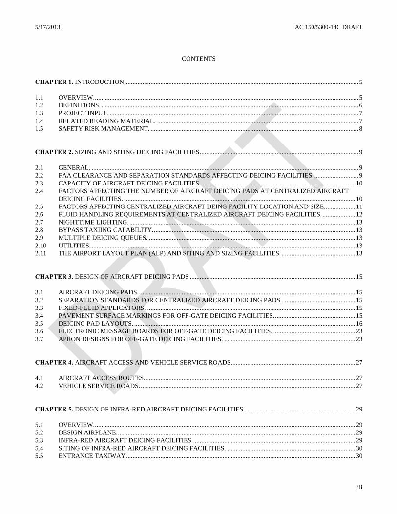
1.1 OVERVIEW. Safe and efficient aircraft operations are of primary importance in the development of any off-gate
aircraft ground deicing facility, referred to as a centralized aircraft deicing facility as shown in figure 1-1. First, this advisory
circular discusses the subjects of sizing, siting, environmental runoff mitigation, and airfield operational requirements to
maximize deicing capacity while maintaining safety and efficiency. Airport operators can construct, within FAA standards,
use terminal gates as an aircraft deicing facility or move this safety function off the gates to a centralized aircraft deicing
facility located along taxiways serving the departure runway. Second, this advisory circular provides design
recommendations and stresses the subject that centralized aircraft deicing facilities have unique deicing/anti-icing operational
issues associated with deicing/anti-icing aircraft that must be addressed. On this latter subject, related material to assist
designers is made available by the Society of Automotive Engineers (SAE) Aerospace Division publication Aerospace
Recommended Practice (ARP) 4902, Design and Operation of Aircraft Deicing Facilities, and ARP 5660, Deicing Facility
Operational Procedures, latest editions. For example, it is preferable that a centralized aircraft deicing facility be operated by
a single service provider. Furthermore, it is recommended that the service provider follow, if possible, agreed-upon
deicing/anti-icing procedures for all users of the facility. The safety benefit of employing common procedures is that it
minimizes confusion of treatment among several air carriers that prescribe different deicing/anti-icing requirements for their
aircraft fleet. This advisory circular recommends that the airport operator address these two subjects prior to the design of the
centralized aircraft deicing facility to ensure the facility’s safety benefits can be achieved in an operationally efficient and
cost-effective manner.
Figure 1-1. Centralized aircraft deicing facility at Cleveland Hopkins International Airport
a. Role of a Centralized Aircraft Deicing Facility. The primary goal of a centralized aircraft deicing facility is
meeting, to the extent practicable, the needs of the air carriers as prescribed in their FAA-approved aircraft ground deicing/anti-
icing program. Achieving this primary goal offers greater operational flexibility among the facility users. To support this
primary goal, the airport operator’s FAA-approved Snow and Ice Control Plan must classify centralized aircraft deicing facilities
as a priority 1 facility for snow clearance time under Advisory Circular 150/5200-30, Airport Winter Safety and Operations.
This action enables the facility to remain fully operational during inclement weather; thereby icing conditions that affect the
safety of flight are better managed.
b. Siting Aircraft Deicing Facilities. This advisory circular identifies an aircraft deicing facility as the use of
terminal gates as an aircraft deicing facility and use of a location away from the terminal gates as a centralized aircraft deicing
facility. As a consequence, centralized aircraft deicing facilities are located along taxi routes (aprons in some cases) leading to
the departure runways.

AC 150/5300-14C DRAFT 5/17/2013
6
(1) Terminal Gates as Aircraft Deicing Facilities. The use of terminal gates to deice/anti-ice aircraft is
the most common option in use today. As a consequence, terminal gates that cannot meet storm water discharge permitting
regulations should be upgraded environmentally when they can under varying weather conditions adequately handle the demand
for aircraft deicing/anti-icing treatments and allow acceptable taxiing times to reach the departure runway.
(2) Centralized Aircraft Deicing Facilities. Centralized aircraft deicing facilities are facilities where
aircraft receive deicing/anti-icing treatment away from the gate, along taxi routes leading to the departure runway(s). Larger
airports have constructed such facilities along numerous taxi routes thereby allowing aircraft to receive deicing/anti-icing
treatment closer to the runway. Two known benefits of facilities built closer to the departure runway are minimizing the taxiing
time between start of treatment and takeoff and avoiding changing weather conditions encountered when aircraft have extra-long
taxi routes.
1.2 DEFINITIONS.
a. Aircraft Deicing Facility. An aircraft deicing facility is a facility where—
(1) frost, ice, slush, or snow is removed (deicing) from the aircraft in order to provide clean surfaces,
and/or
(2) clean surfaces of the aircraft receive protection (anti-icing) against the formation of frost or ice and
accumulation of snow or slush for a limited period of time (referred to as the “holdover time”).
b. Centralized Aircraft Deicing Facility. A centralized aircraft deicing facility is an aircraft deicing facility
located along taxiways leading to the departure runway or on an apron away from the terminal gates where aircraft receive
deicing/anti-icing treatment.
c. Aircraft Deicing Pad. An aircraft deicing pad, where aircraft receive treatment, consists of two areas (see
figure 1-2):
(1) inner area for the parking of aircraft to receive deicing/anti-icing treatment, and
(2) outer area for maneuvering two or more mobile deicing vehicles.
MANEUVERING
AREA FOR MOBILE
DEICING VEHICLES
(INCLUDES AIRCRAFT
PARKING AREAS)
AIRCRAFT
PARKING AREA
Figure 1-2. Aircraft deicing pad with vehicle maneuvering area
d. Holdover Time. Holdover time is the estimated time the application of anti-icing fluid will prevent the
formation of frozen contamination on the protected surfaces of an aircraft. With a one-step deicing/anti-icing operation, the
holdover begins at the start of the operation; with a two-step operation, at the start of the final anti-icing application.
Holdover time will have effectively run out when frozen deposits start to form/accumulate on the treated aircraft surfaces.
For departure planning purposes, holdover time guidelines for various anti-icers, such as Types I, II, and IV, are published.
Guidelines for using holdover times are found in the latest edition of SAE ARP 4737, Aircraft Deicing/Anti-icing Methods.

7
5/17/2013 AC 150/5300-14C DRAFT
7
FAA publishes Holdover Tables at http://www.faa.gov/other_visit/aviation_industry/airline_operators/airline_safety/deicing/.
The Association of European Airlines (AEA) cautions that: “Due to the many variables that can influence holdover times,
these times should not be considered minimum or maximum as the actual time of protection may be reduced or extended,
depending upon particular conditions existing at the time.”
1.3 PROJECT INPUT. Because each airport is unique, deicing/anti-icing needs of users are better addressed when
affected parties help identify the requirements for deicing facilities.
a. Affected Parties. Airport management should solicit input from the following parties:
(1) Station/operations managers of tenant air carriers, regional, and commuter air carriers,
(2) Ground deicing managers of air carrier, regional, and commuter air carriers, and the service
provider contracted with treatment responsibility
(3) FAA Air Traffic Control, Airports Division, Technical Operations, and Flight Standards Offices,
(4) Airport operations chief, environmental manager, and the aircraft rescue and firefighting chief,
(5) Pilot organizations or representatives, air taxis, and general aviation users,
(6) Engineering design contractor, and
(7) Other parties at the discretion of airport operator.
b. Other. The FAA recommends that airports involve or inform Federal, state, and local environmental
authorities having jurisdiction early in the facility development process to ensure compliance with storm water permitting
requirements. The addition of a centralized deicing operation will result in the need to update permits and plans. Review of
aircraft deicing facility plans by environmental authorities is a significant step toward compliance with U.S. Environmental
Protection Agency National Pollutant Discharge Elimination System (NPDES) storm water permitting requirements per 40
CFR 122.26 and 40 CFR Part 449.
1.4 RELATED READING MATERIAL. Publications referenced in this AC are available from the following
organizations:
a. FAA ACs, www.faa.gov.
b. Society of Automotive Engineers (SAE), 400 Commonwealth Drive, Warrendale, PA 15096-0001, or
www.sae.org.
c. The International Organization for Standardization, Case Postal 56, Rue de Varembe, CH-1211
Geneva 20, Switzerland, or www.iso.org.
d. Airport Cooperative Research Program (ACRP), Guidebook for Selecting Methods to Monitor Airport and
Aircraft Deicing Materials by the Transportation Research Board (TRB), http://www.trb.org/main/blurbs/167504.aspx
e. National Fire Protection Association (NFPA), 1 Batterymarch Park, Quincy, MA 02169-7471, or
www.nfpa.org.
f. American Society for Testing and Materials (ASTM) International, 100 Barr Harbor Drive, PO Box
C700, West Conshohocken, PA, 19428-2959, or www.astm.org.
g. Association of European Airlines, www.aea.be.

AC 150/5300-14C DRAFT 5/17/2013
8
1.5 SAFETY RISK MANAGEMENT. Safety Risk Management analysis must be performed before a deicing
pad/facility construction project is initiated.

9
5/17/2013 AC 150/5300-14C DRAFT
9
CHAPTER 2. SIZING AND SITING DEICING FACILITIES
2.1 GENERAL. Aircraft deicing facilities are recommended at airports where icing conditions are expected. This
includes airports that serve aircraft that can develop frost or ice on critical surfaces even though the airport itself does not
experience ground icing conditions. Aircraft deicing facilities are located either at the gates or away from the gate areas. The
latter location is referred to a centralized aircraft deicing facility.
a. Terminal Gates as Aircraft Deicing Facilities. The use of gates as aircraft deicing facilities have
demonstrated that under varying weather conditions they can adequately meet the deicing/anti-icing demands of users and allow
acceptable taxiing times to the departure runways. The phrase “acceptable taxiing times” implies that the taxiing time and the
weather conditions encountered from the gates to the departure runway do not exceed the holdover time (effectiveness) of
applied fluids. To comply with Federal, state, and local environmental discharge permits of aircraft de/anti-icing fluids,
improvements to or expansion of such gate facilities should, if practicable, include apron drainage areas, systems that collect
aircraft glycol runoff for proper disposal or recycling.
b. Centralized Aircraft Deicing Facility. Centralized aircraft deicing facilities are recommended for airports
when (1) gate facilities experience excessive gate delays or lack of gates for treatment or (2) the holdover time of applied glycols
are exceeded frequently because of the taxiing times to arrive at the departure runway or because the taxi route encounters a
variety of weather conditions. Reported benefits of such facilities is that they have improved airfield flow and permit
retreatment of aircraft nearer the departure runway instead of returning the aircraft back to the gates. Some airports have built
such facilities because the construction cost to improve runoff mitigation is not cost-effective at the terminal.
c. Basic Components of Centralized Aircraft Deicing Facilities. Centralized aircraft deicing facilities have
the following basic components:
(1) aircraft deicing pad(s) for maneuvering aircraft and mobile deicing vehicles,
(2) bypass taxiing capability for aircraft not needing treatment,
(3) environmental runoff mitigation measure,
(4) control center (snow desk) building (see figure 2-1),
(5) permanent or portable nighttime lighting system, and, but not necessarily,
(6) deicing crew shelter with kitchen and toilet facilities,
(7) co-located support facilities that may include one or more of the following:
(a) storage tank(s), transfer system(s) for approved aircraft deicing/anti-icing fluid(s),
(b) fixed-fluid applicator (turret applicators instead of mobile deicing vehicle).
2.2 FAA CLEARANCE AND SEPARATION STANDARDS AFFECTING DEICING FACILITIES. To ensure
aircraft safety, the location and operation of centralized aircraft deicing facilities must follow the clearance and separation
standards specified in the latest edition of AC 150/5300-13, Airport Design. These standards involve airspace and aircraft
separations, NAVAID critical areas for FAA technical operations facilities, and line-of-sight criteria for the airport traffic control
tower.
a. Object Clearance Criteria. Centralized aircraft deicing facilities must be sited in accordance with object
clearing criteria described in AC 150/5300-13 which include facilities located in the movement area (under ATCT control) or
non-movement area (not under ATCT control). If the airport is land constrained or sufficient physical space to proposed site is
limited, the airport operator can site the facility in a non-movement area, i.e., an area not under direct ATCT control. The

AC 150/5300-14C DRAFT 5/17/2013
10
benefit of this decision is that smaller wing tip clearance criteria is permissible, i.e., taxilane centerline criteria versus taxiway
centerline criteria. Depending on the site conditions, the airport operator could negotiate with the ATCT manager to redefine a
portion of the movement area as a non-movement area to site the facility.
Figure 2-1. Example of a centralized aircraft deicing facility Snow Desk
b. FAA Technical Operations. Centralized aircraft deicing facilities must be located so as not to cause signal
interference or signal degradation to existing FAA radar, navigational aids (NAVAIDs), airport lighting, weather facilities,
communications, etc. This includes interference or degradation caused by such facilities having aircraft deicing fluid storage
tanks, crew shelters, and permanent nighttime lighting structures. If any FAA radar, navigational aid improvements are planned,
sufficient obstacle clearances, as required by new facilities, must be protected. Some airports may require additional FAA
communications equipment to meet the operational needs of the centralized aircraft deicing facility. Additional communications
equipment installations may result from increased ground control frequencies necessary for the ATCT to provide safe flow of
airport ground traffic and to enable ground deicing personnel to conduct safe deicing operations. In all cases, the installation of
communications equipment and assignment of frequencies need to be coordinated with FAA Technical Operations prior to the
construction of centralized deicing facilities. To further protect FAA installations, proposed sites must be evaluated to assess the
impact of jet blast velocities and exhaust deposits on such installations. This coordination must also take place through
coordination with the respective Airport Regional and District/Development Offices.
c. ATCT Line-of-Sight. The centralized aircraft deicing facility and its supporting structures must minimize
reductions to ATCT’s visual view of the entire movement area. To maintain ATCT’s visual view, aircraft receiving treatment
should not obstruct ATCT’s line-of-sight to active runway ends and their supporting taxiways. To minimize “shadows” created
by aircraft awaiting treatment, aircraft with the largest surfaces and tail sections to be treated should be evaluated. Visual view
of the entre movement area by planned ATCT cab position(s) should always be evaluated.
2.3 CAPACITY OF AIRCRAFT DEICING FACILITIES. Airports that need aircraft deicing facilities (either at the
gates or centralized off the gates) should balance the required treatment capacity of the users with the airport’s peak hour
departure rate during snow/icing conditions. This balance may be achieved by using only gates, a combination of gates and a
centralized aircraft deicing facility, or just a centralized aircraft deicing facility. Paragraph 2-4 discusses the factors that
determine the number of aircraft deicing pads within a centralized aircraft deicing facility.
2.4 FACTORS AFFECTING THE NUMBER OF AIRCRAFT DEICING PADS AT CENTRALIZED AIRCRAFT
DEICING FACILITIES. If a centralized aircraft deicing facility is used, the designer needs to determine the
number of aircraft to be treated for a set time away from the gates, the individual times to treat aircraft for various weather
conditions (wet snow, pellets, freezing drizzle, cold rain, etc.), and the types of aircraft to be treated since some aircraft
configurations require longer treatment than other aircraft. These evaluations lead to a proposed number of deicing pads at
the facility. The final number of deicing pads should relate back to the airport’s peak hour departure rate during snow/icing
conditions. Another factor worth evaluation is the number of aircraft requiring re-treatment (exceeded holdover time.)
Because the type and size of aircraft configurations bear on the number of deicing pads, it is recommended that the designer
take into account future aircraft fleets for a planning period of at least 10 years. This type of information is available from
the air carriers (e.g., anticipated airline service and aircraft on order) and airframe manufacturers.

11
5/17/2013 AC 150/5300-14C DRAFT
11
a. Number of Deicing Pads. Evaluating the impact of the following factors provides a better estimate of the
number of deicing pads needed at a facility.
(1) Procedures and Methods of Users. Facility users will receive either one-step or two-step
deicing/anti-icing treatment. The latter procedure routinely used during periods of active precipitation, results in longer
occupancy times at deicing pads. It is recommended that to provide users with procedural flexibility, the number of deicing pads
be based on the two-step approach. Furthermore, increases to this occupancy time may be needed to reflect differences in the
methods used to treat aircraft and perform preflight inspections. It is not unusual for users to supplement preflight inspection
items recommended by aircraft manufacturers with additional items for aircraft having special operational conditions.
(2) Variations in Meteorological Conditions. Variations in meteorological conditions, e.g., type of
precipitation, increase the extent (and frequency) of the deicing/anti-icing treatment. Airports that commonly experience heavy
wet snows or freezing rain should increase the number of deicing pads to maintain departure flow rates at levels that avoid
unacceptable delays for subsequent aircraft awaiting treatment. If revised flow control procedures fail to prevent meteorological
conditions from frequently degrading the holdover time used for the initial treatment, the airport should consider a facility closer
to the active runway. To the extent practicable, there should be a balance between the number of aircraft deicing facilities (at
gates and off gates) and their location to offset severe meteorological conditions so holdover times are in effect at takeoff.
(3) Type of Aircraft Receiving Treatment. The processing time to deice/anti-ice aircraft for the same
weather conditions and fluids varies by aircraft types. Narrow-body aircraft are processed quicker than wide-body aircraft, and
aircraft with center fuselage mounted engines, such as DC-10s and Boeing 727s, require additional processing time. Airports
with a high percentage of narrow-body aircraft and a low percentage of wide-body aircraft may need additional deicing pads to
adequately maintain this particular fleet’s departure demand. A balanced fleet mix may provide a means of increasing a
facility’s deicing capacity by relating flow rates of common-sized aircraft to specific deicing pads.
(4) Heating Performance and Volume Capacity of Mobile Deicing Vehicles. Additional deicing
pads may be needed if users operate mobile deicing vehicles with small tank capacities or vehicles that require extended periods
of time to heat fluids after refilling (that is, times approaching 20 minutes). Nearby refilling points can help offset such
increases.
(5) Centralized Aircraft Deicing Facilities. Depending on the airport, construction of a centralized
aircraft deicing facility may counter some or all of the above factors.
b. Number of Deicing Facilities. The estimated number of deicing pads plus other structural and operational
needs of a centralized aircraft deicing facility determine the approximate physical space requirement for siting the facility. Once
the facility’s overall physical size requirement is known, the search for suitable sites follows within the framework of safety and
operational siting factors cited in this AC, plus latest edition of AC 150/5300-13.
(1) Multiple Deicing Facilities. When the estimated number of deicing pads cannot be physically sited
or operationally managed (such as under usual poor weather conditions) at a single site, the airport operator should consider
additional centralized facilities.
(2) Type of Facility User. Airports serving a wide variety of scheduled service by main line, regional,
or commuter air carriers and nonscheduled service by air taxi, general aviation aircraft, and charters may better meet their
deicing/anti-icing needs by constructing a separate deicing facility for a group. If a single facility is identified for all airport
users, additional physical space may be necessary to meet the specific needs for one of the groups, e.g., facilities that store
appropriate, approved deicing/anti-icing fluids for smaller aircraft.
2.5 FACTORS AFFECTING CENTRALIZED AIRCRAFT DEING FACILITY LOCATION AND SIZE. The
primary factor for siting centralized aircraft deicing facilities is the taxiing time that begins with the start of the last step of the
deicing/anti-icing treatment and ends with takeoff clearance, such that the holdover times of applied fluids are still in effect. The
analysis should use slower taxiing speeds experienced under winter-contaminated conditions as well as other time-contributing
factors specific to the airport. SAE ARP 4737 and ISO 11076, Aircraft – Ground-based Deicing/Anti-Icing Methods with
Fluids, provide departure planning holdover procedures for various anti-icers, such as Type I and Type IV, which assist in

AC 150/5300-14C DRAFT 5/17/2013
12
balancing holdover times and winter taxiing times from the facility to takeoff point. Other factors involved in locating facilities
follow.
a. Restrictions on Deicing/Anti-icing Fluids. Restrictions on deicing fluid usage can impact the siting of
centralized aircraft deicing facilities. Though used for the same weather conditions, non-Newtonian fluids, such as Type II
and Type IV, provide longer holdover times than Type I, a Newtonian fluid, but they are restricted to aircraft with higher
takeoff rotational speeds (e.g., 100 knots or as approved by airframe manufacturers). This restriction may necessitate siting a
facility closer to the departure runway in order to serve restricted aircraft or to have separate facilities for the two groups.
Also, facility siting may have to take into account airports that are located in very cold climates since Type II fluids have a
lower temperature application limit, i.e., -13 F (-25 C).
b. Effects of Fluid Applicators.
(1) Mobile Deicing Vehicles. Normally, the use of mobile deicing vehicles as compared to fixed-fluid
applicators increases the number of suitable sites for facilities by permitting closer construction to active runways. However, for
certain airports, a close site may require construction of new service roads and/or staging areas to allow such vehicles to serve
the facility.
(2) Fixed-Fluid Applicators. Use of fixed-fluid applicators, such as a gantry, telescopic booms, etc.,
will limit the number of suitable sites due to height restrictions (see AC 150/5300-13, Object Clearing Criteria). However, this
type of applicator may allow airports to reduce vehicle traffic and escorting demands or compensate for the lack of service roads
and staging areas. If fixed-fluid applicators are installed, each deicing pad still must have sufficient outer maneuvering area for
two mobile deicing vehicles.
c. Fleet Mix. The physical space required by deicing facilities depends to some degree on the fleet mix being
served. For instance, airports serving a large variety of aircraft types and sizes may require facilities more flexible and complex
than those airports serving predominantly one class of aircraft.
d. Existing Taxiing Routes. Before siting deicing facilities away from the terminal areas, an airport should first
evaluate the use of existing taxiways that minimize the taxiing time to the facility and, more important, the subsequent taxiing time
remaining between treatment and takeoff.
e. Environmental Runoff Alternative. The cost-effective environmental alternatives available to the airport to
control deicer runoff may reduce the number of sites suitable for a deicing facility. For example, land-locked airports near large
bodies of water may have to site a facility closer to existing sanitary sewers than to departure runways. It is noted that
acceptable alternatives to mitigate deicer runoff will vary according to city, county, and state environmental runoff regulations
imposed on each airport site.
f. Integrating Airport Safety Programs. When identifying deicing/anti-icing requirements, the airport should
look for ways of integrating current airport safety programs with the operation of the deicing facility, thereby continuing airport
safety initiatives. For instance, the runway incursion program at busy airports may be maintained by widening service roads for
bi-directional traffic or by designating additional staging areas instead of constructing separate roads. Other potentially affected
safety programs include the airport’s Surface Movement Guidance and Control System (SMGCS), Emergency Plan and the
Snow and Ice Control Plan. More than likely, there will be changes to the last plan. For instance, the airport may need to
reclassify previously non-cleared service roads to departure runways to priority 1 snow clearing status that will be needed by
deicing vehicles or authorized personnel to conduct post-treatment exterior checks of the aircraft surface.
2.6 FLUID HANDLING REQUIREMENTS AT CENTRALIZED AIRCRAFT DEICING FACILITIES.
a. Storage Tank and Fluid Transfer System Designs. Overheating, excessive mechanical shearing, or
contamination, e.g., from corroded tanks, may degrade the holdover characteristics of non-Newtonian fluids. Non-Newtonian
fluids are Type II, Type III, and Type IV. Newtonian fluids are Type I (see SAE ARP 4737, for fluid classifications). To
protect the performance characteristics of these fluids from degradation, storage tanks and fluid transfer systems installed at

13
5/17/2013 AC 150/5300-14C DRAFT
13
deicing facilities must be designed in accordance with the fluid manufacturer’s recommendations. Fluid transfer systems must
be dedicated to the specific fluid being handled to prevent the inadvertent mixing of fluids of different types or different
manufactures. Fluid manufacturers should provide the airport manager recommendations about compatible pumps, control
valves, piping, and compatible storage tanks. Additionally, SAE ARP 4737 provides industry recommended practices for storage
tank and transfer systems.
b. Separate Storage Tank Capacity. Deicing facilities using various types of deicing/anti-icing fluids will
require more physical space to permit separate storage of fluids. Fluid manufacturers should always be consulted for storage
tank requirements, maintenance, and precautions for currently used fluids and new products entering the market.
c. Tanks, Fill Ports, and Discharge Points Labeling. To avoid cross-contamination of deicing fluids at a
deicing facility, all tanks, fill ports, and discharge points must be conspicuously labeled for the type of fluid handled, e.g., SAE
TYPE I AIRCRAFT DEICING FLUID, ISO TYPE II AIRCRAFT DEICING FLUID.
2.7 NIGHTTIME LIGHTING. All facilities (gate and centralized locations) will provide permanent nighttime lighting
structures or have portable nighttime lighting systems available so ground crews that have the necessary illumination for
deicing/anti-icing operations and pre-takeoff inspections during night or low-visibility conditions. One portable alternative is
mobile deicing vehicles with modified lights that provide sufficient illumination for deicing/anti-icing treatments and pre-takeoff
inspections during night or low visibility. AC 150/5360-13, Planning and Design Guidelines for Airport Terminal Facilities,
provides general lighting requirements for gate-related functions. The height of lighting poles must be in accordance with latest
edition of AC 150/5300-13 Object Clearing Criteria. Permanent nighttime lights should be aimed and shielded to avoid glare to
pilots and the ATCT’s line-of-sight without reducing the illumination of critical areas.
2.8 BYPASS TAXIING CAPABILITY. To further maximize departure flows for all departing aircraft, potential sites
should have enough physical space to allow bypass taxiing capability for aircraft not needing de/anti-icing treatment. This
feature permits the centralized aircraft deicing facility to receive aircraft that require treatment, while allowing other aircraft to
continue unimpeded for departure. Figure 2-2 provides an example.
2.9 MULTIPLE DEICING QUEUES. Gains in deicing capacity at off-gate facilities are possible when deicing pads
have individual entrance and exit queuing capabilities (for example, see figures 3-2, 3-3, and 3-4). These features give the ATCT
greater flexibility to receive aircraft from the service provider and issue departure clearances without subjecting aircraft to a “first-
in/first-out” queuing situation. Such design features are recommended, if practicable, for centralized aircraft deicing facilities that
experience extended periods of operation under continuous poor weather conditions.
2-10. TOPOGRAPHY. Topography is a key cost factor in constructing a deicing facility.
a. Final Grades. To reduce construction costs, facilities should be sited on relatively flat land where the natural
terrain features conform to the final grades for the ultimate design of the deicing facility.
b. Drainage Areas. Sites with high water tables that require costly subdrainage and a runoff mitigation
alternative should be avoided. The final site should readily lend itself to facility runoff mitigation at reasonable cost. AC
150/5320-5, Surface Drainage Design, provides design standards for airfield drainage systems.
2.10 UTILITIES. Although utility considerations are subordinate to other siting factors, the airport manager should
evaluate whether to extend water supply, electric power, telephone service and sanitary or storm sewers to support an off-gate
facility. For some situations, independent service installations or a separate runoff mitigation alternative at the site may be more
cost-effective.
2.11 THE AIRPORT LAYOUT PLAN (ALP) AND SITING AND SIZING FACILITIES. Review of the airport’s
ALP provides information that should simplify the siting and sizing process. Some ALPs delineate planned land acquisition
areas adjacent to airport property for airport development. Consequently, a revision can show areas identified for a deicing
facility. Any changes to the ALP should be considered carefully and all changes documented and submitted to the FAA for
approval.

AC 150/5300-14C DRAFT 5/17/2013
14
SEPARATE
TAXIWAY
ENTRANCE
Figure 2-2. Separate taxiing entrance to a centralized aircraft deicing facility (non-movement area)

15
5/17/2013 AC 150/5300-14C DRAFT
15
CHAPTER 3. DESIGN OF AIRCRAFT DEICING PADS
3.1 AIRCRAFT DEICING PADS. The size of an aircraft deicing pad is determined by the aircraft parking area and
the maneuvering area for mobile deicing vehicles as shown in figure 1-2.
a. Aircraft Parking Area. This area is the inner area used for parking aircraft to receive deicing/anti-icing
treatment.
(1) Width. The width of the parking area equals the upper wingspan of the most demanding airplane
design group (ADG) using the deicing pad.
(2) Length. The length of the parking area equals the fuselage length of the most demanding aircraft
using the deicing pad.
b. Maneuvering Area for Mobile Deicing Vehicles. This outer area provides the “vehicle lane width”
necessary for two or more mobile deicing vehicles to satisfactorily perform simultaneous and complete left- and right-side
uniform fluid distribution techniques for removing deposits of frost, ice, slush, and snow from aircraft surfaces and for anti-
icing operations. The vehicle lane width must be 12.5 feet (3.8 m) and be mutually exclusive of any adjacent deicing pad.
As previously noted by SAE ARP 4737, “Dual vehicle fluid applications help in eliminating potential aerodynamic problems
resulting from fluid applications by a single mobile deicing vehicle.”
3.2 SEPARATION STANDARDS FOR CENTRALIZED AIRCRAFT DEICING PADS. Aircraft deicing pads for
centralized aircraft deicing facilities will have parallel taxiway centerlines. Separation criteria provided in table 3-1 takes
into account the need for individual deicing pads to provide sufficient maneuvering area around the aircraft to allow
simultaneous treatment by two or more mobile deicing vehicles (see paragraph 1-2(d)(2) and figure 1-2) and, with the exception
of column #5 of table 3-1, sufficient non-overlapping space for a vehicle safety zone (VSZ) between adjacent deicing pads (see
paragraph 3-4(d)) and for the outer deicing pads. For example, a centralized aircraft deicing facility with three deicing pads will
have three vehicles maneuvering areas (VMAs) and four VSZs. Table 3-1 observes taxiway centerline to fixed or movable
object criteria because VSZs house fixed and movable objects. Furthermore, table 3-1 entries and footnotes ensure that
sufficient separation exists between taxi centerlines and VSZs and VMAs. Table 3-1 offers airport operators the option to
locate centralized aircraft deicing facilities in the movement area or non-movement areas. Column #5, off-gate deicing
facilities without vehicle safety zones, reflects the practice by airport operators to designate on a temporary basis the use of
suitable apron areas, near a departure runway or adjacent to terminal gates, for deicing/anti-icing airplanes. Temporary off-
gate facilities may have vehicle safety zones, but they generally lack the infrastructure that is associated with permanent
centralized aircraft deicing facilities, such as a snow control center with a crew shelter, overhead lighting, and possibly
electronic message boards.
3.3 FIXED-FLUID APPLICATORS. Fixed-fluid applicators should satisfactorily perform simultaneous and complete
left- and right-side uniform fluid distribution techniques for removing deposits of frost, ice, slush, and snow from aircraft
surfaces and for anti-icing operations. Fixed-fluid applicators, such as gantries or telescopic booms, have the advantage of
reducing vehicle traffic and may lower the quantities of fluid used. Though fixed-fluid applicators may be the primary
deicing applicators for a deicing pad, the pad must have enough maneuvering area for mobile deicing vehicles to provide
secondary backup capabilities in case of primary equipment failure.
3.4 PAVEMENT SURFACE MARKINGS FOR OFF-GATE DEICING FACILITIES.
a. Taxiway Centerline Surface Marking. Centralized aircraft deicing facilities will have only yellow
taxiway centerline surface markings for entering the facility, moving through the deicing pad, and exiting the facility. The
surface marking must be in accordance with AC 150/5340-1, Standards for Airport Markings. At airports operating below
1,200 feet runway visual range (RVR), centralized aircraft deicing facilities located on a designated SMGCS low-visibility
taxi route (see AC 120-57, Surface Movement Guidance and Control System (SMGCS)) may require additional taxiing route
surface marking, lighting, and sign systems necessary to support SMGCS operations.

AC 150/5300-14C DRAFT 5/17/2013
16
b. Facility Boundary Surface Markings. Centralized aircraft deicing facilities shall have either the
taxiway/taxiway intermediate holding position surface marking for facilities under direct ATCT control or the non-
movement boundary surface marking for facilities not under ATCT control but by a service provider - Snow Desk (figures 2-
2, 3-2, 3-3). Both markings indicate the entrance and exit boundary points of the facility and must be painted in accordance
with paragraph 3-4(b)(1) and (b)(2) of this advisory circular. The intent of both markings is to reduce intrusions by deicing
crews and aircraft into the object free area of nearby and connecting taxiways during daytime or low-visibility conditions.
The importance of the second marking is that it identifies the ground control transfer points between the ATCT and Snow
Desk control center. Lighted signage may be used instead of surface markings only at the facility entrance. If lighted signs
are used, they must be in accordance with AC 150/5340-18, Standards for Airport Sign Systems, latest edition.
(1) Surface Marking. The taxiway/taxiway holding position surface marking (perimeter of the
facility under ATCT control) and the non-movement boundary surface marking (facility not under ATCT control) must be in
accordance with latest edition of AC 150/5340-1 (see example figure 3-2 and 3-3).
(2) Composite Deicing Pad Surface Markings. If a single deicing pad will serve as a composite
deicing pad (or “grouping”) such as pad #5 in figure 3-3, which incorporates pads #4 and #6, then a single entrance taxiway
centerline surface marking will be used for the grouping. After a given distance, the single entrance centerline will separate
into individual taxiway centerlines for the incorporated deicing pads. Each individual taxiway centerline entrance within the
grouping will be marked with its own deicing pad identifier. Since these pads are used as a grouping, the deicing pad
identifiers will use the same alpha character followed by a different numeric character. For example, the pad grouping #4,
#5, and #6 would be identified as D2, D1, and D3, respectively, with the main entrance taxiway centerline serving pad #5
designated as D1.
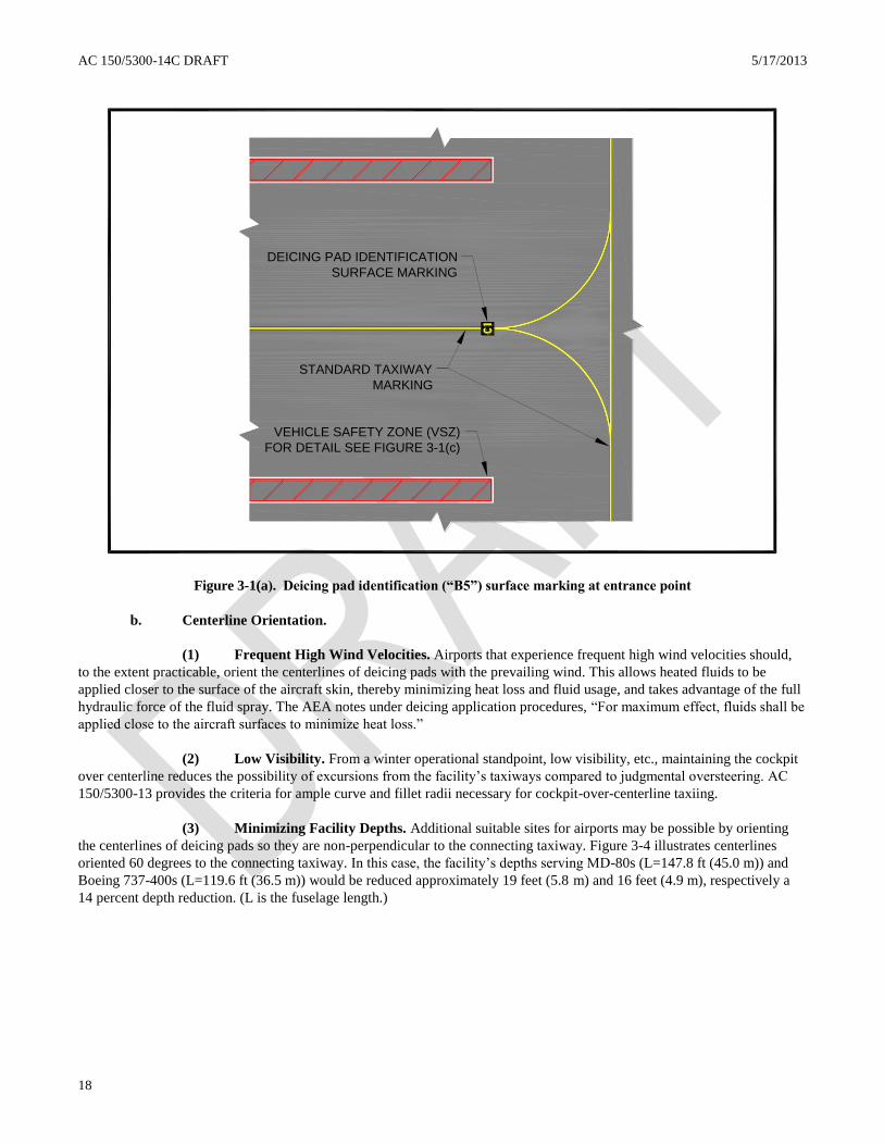
c. Vehicle Safety Zone Surface Markings. Each deicing pad at the facility must have a vehicle safety zone
(VSZ) surface marking on each side of its taxiway centerline in accordance with figure 3-1(b). The VSZ functions as a safety
zone for personnel and parked deicing vehicles and other equipment before and after deicing/anti-icing operations. For a
composite deicing pad (grouping), such as pads #4, #5, #6 in figure 3-3, three VSZs are provided for the grouping, one VSZ
to the left of pad #4 and the other VSZ to the right of pad #6 and one VSZ centered along the centered taxiway centerline.
The “centered VSZ” however has a 1-foot gap between the red painted VSZ and the yellow taxiway centerline as shown in
figure 3-3.
(1) Width of VSZs. The minimum width for the VSZ is 10 feet (3.0 m), which restricts vehicle
parking to “face-to-face” instead of “side-by-side”. The minimum width of the “centered VSZ” is the same, even though
figure 3-3 illustrates a wider VSZ to illustrate a gap between the taxiway centerline and the VSZ marking.
(2) Overall Length of VSZs. The overall continuous length of the VSZ should offer “trouble-free”
parking of the vehicle fleet required to perform the deicing/anti-icing operations. In all cases, the overall continuous length
will be such that neither end of the VSZ violates the taxiway/taxilane object free area of taxiways or taxilanes located outside
the boundary of the deicing facility. Depending on the jet blast profiles of certain aircraft, the length of the VSZ toward the
exit side of the facility may need to be reduced to minimize severe jet blast impacts onto parked vehicles and personnel when
the aircraft exits and turns onto the connecting taxiway.
(3) Location of VSZs. Case 1 – Placement of VSZs between adjacent deicing pads will be in
accordance with paragraph 3-2 of this AC. Case 2 – Placement of the VSZ on the outermost deicing pad will be in
accordance with fixed/movable criteria specified in latest edition of AC 150/5300-13.
3.5 DEICING PAD LAYOUTS. Layouts for deicing pads should maximize the flexibility of deicing operations and
reduce ATCT workloads. The following layouts provide alternatives for varying weather conditions.
a. Layouts.
(1) Common Deicing Pad Layout. A common deicing pad layout has a single centerline through the
deicing pad to guide all sized aircraft. For facilities serving a fleet mix with numerous wide-body aircraft, separating deicing
pads for wide-body aircraft from other aircraft may increase deicing capacity (see pad #1 in figure 3-2).

17
5/17/2013 AC 150/5300-14C DRAFT
17
(2) Composite Deicing Pad Layout. A composite deicing pad layout has more than one centerline
through the deicing pad to guide different sized aircraft. For facilities serving a balanced mix of different sized aircraft,
correlating the percentages of aircraft types to their departure rates may increase deicing capacity (see figure 3-3). When two
aircraft use a common centerline, additional parking space between aircraft may be needed to account for exiting jet blast
degradation of Types II or IV protective coatings and velocities on personnel/equipment (see paragraph 3-5c(1)).
Table 3-1. Separation criteria for centralized aircraft deicing pads having parallel taxiways
Airplane
Design
Group2
(ADG)
Off-Gate Aircraft Deicing Facilities
Non-Movement Area1 Movement Area
1
Column #13
Outer Deicing Pad
Taxi Centerline
(CL) to Edge of
Vehicle Safety
Zone (VSZ)
Column #23
Interior Deicing
Pads
Taxi CL to
Taxi CL
Column #33
Outer Deicing Pad
Taxi CL to
Edge of VSZ
Column #43
Interior Deicing
Pads
Taxi CL to
Taxi CL
Column #5 4
Temporary Deicing
Pads
Taxi CL to
Taxi CL
Includes
1 Vehicle
Maneuvering Area
(VMA)
Includes
2 VMAs + 1 VSZ
Includes
1 VMA
Includes
2 VMAs + 1 VSZ
Includes
VMAs and no VSZ
ADG VI 167 ft
(51 m)
344 ft
(105 m)
193 ft
(59 m)
396 ft
(120.5 m)
324 ft
(99 m)
ADG V 138 ft
(42 m)
286 ft
(87 m)
160 ft
(48.5 m)
330 ft
(100.5)
267 ft
(81 m)
ADG IV 112.5 ft
(34 m)
235 ft
(71.5 m)
129.5 ft
(39.5 m)
269 ft
(82 m)
215 ft
(65.5 m)
ADG III 81 ft
(24.5 m)
172 ft
(52.5 m)
93 ft
(28.5 m)
196 ft
(59.5 m)
152 ft
(46.5 m)
ADG II 57.5 ft
(17.5 m)
125 ft
(38 m)
65.5 ft
(20 m)
141 ft
(43 m)
105 ft
(32 m)
ADG I 39.5 ft
(12 m)
89 ft
(27 m)
44.5 ft
(13.5 m)
99 ft
(30 m)
74 ft
(22.5 m)
The values obtained from the following equations may be used to show that a modification of standard will provide an
acceptable level of safety. Refer to paragraph 6 of AC 150/5300-13 for guidance on modification of standard requirements.
Column No. 1: Taxilane CL to fixed or movable object equals 0.6 times airplane wingspan (WS) plus 10 feet - [(0.6)(WS) +
10] for all ADGs.
Column No. 2: Taxilane CL to parallel taxilane CL with fixed or movable object equals [(1.2)(WS) + 30] for all ADGs, plus
with ADG I, wingspans less than 25 feet require sufficient separation for two VMAs and one VSZ.
Column No. 3: Taxiway CL to fixed or movable object equals [(0.7)(WS) + 10] for all ADGs.
Column No. 4: Taxiway CL to parallel taxiway CL with fixed or movable object equals [(1.4)(WS) + 30] for all ADGs, plus
with ADG I, wingspans less than 15 feet require sufficient separation for two VMAs and one VSZ.
Column No. 5: Taxiway CL to parallel taxiway CL equals [(1.2)(WS) + 10] for ADGs III – VI. Apply the same equation for
ADGs I and II, but wingspans less than 75 feet require sufficient separation for two VMAs and no VSZ.
Note 1: Facilities built in non-movement areas are not under direct ATCT control. Facilities built in movement areas are under
direct ATCT control.
Note 2: ADGs are defined in AC 150/5300-13, paragraph 2. Table 3-1 values assume largest airplane wingspan within each
ADG.
Note 3: Columns #1 – 4 have a 12.5-foot (3.8-m) wide VMAs and a 10-foot (3-m) wide VSZ.
Note 4: Column #5 has 12.5-foot (3.8-m) wide VMA and no VSZ.
AC 150/5300-14C DRAFT 5/17/2013
18
VEHICLE SAFETY ZONE (VSZ)
FOR DETAIL SEE FIGURE 3-1(c)
STANDARD TAXIWAY
MARKING
DEICING PAD IDENTIFICATION
SURFACE MARKING
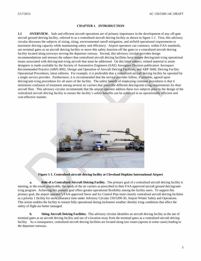
Figure 3-1(a). Deicing pad identification (“B5”) surface marking at entrance point
b. Centerline Orientation.
(1) Frequent High Wind Velocities. Airports that experience frequent high wind velocities should,
to the extent practicable, orient the centerlines of deicing pads with the prevailing wind. This allows heated fluids to be
applied closer to the surface of the aircraft skin, thereby minimizing heat loss and fluid usage, and takes advantage of the full
hydraulic force of the fluid spray. The AEA notes under deicing application procedures, “For maximum effect, fluids shall be
applied close to the aircraft surfaces to minimize heat loss.”
(2) Low Visibility. From a winter operational standpoint, low visibility, etc., maintaining the cockpit
over centerline reduces the possibility of excursions from the facility’s taxiways compared to judgmental oversteering. AC
150/5300-13 provides the criteria for ample curve and fillet radii necessary for cockpit-over-centerline taxiing.
(3) Minimizing Facility Depths. Additional suitable sites for airports may be possible by orienting
the centerlines of deicing pads so they are non-perpendicular to the connecting taxiway. Figure 3-4 illustrates centerlines
oriented 60 degrees to the connecting taxiway. In this case, the facility’s depths serving MD-80s (L=147.8 ft (45.0 m)) and
Boeing 737-400s (L=119.6 ft (36.5 m)) would be reduced approximately 19 feet (5.8 m) and 16 feet (4.9 m), respectively a
14 percent depth reduction. (L is the fuselage length.)
19
5/17/2013 AC 150/5300-14C DRAFT
19
PAD BORDER
(12 IN WIDE
WHITE STRIPE)
VEHICLE BORDER
(6 IN MINIMUM WIDE
RED STRIPE)
2 IN MINIMUM SPACE
BETWEEN WHITE PAD AND
RED VEHICLE BORDERS
OPTIONAL 45° DIAGONAL STRIPING
(6 IN WIDE RED STRIPE, SPACED
15 FT MAXIMUM APART)
10 FT
MINIMUM
Figure 3-1(b). Vehicle safety zone surface marking standards

AC 150/5300-14C DRAFT 5/17/2013
20
DEICING FACILITY
BOUNDARY SURFACE
MARKING
VEHICLE SAFETY
ZONE (VSZ)
MARKING
TAXIWAY B
DEICING PAD
IDENTIFICATION
MARKING
TAXIWAY A
Figure 3-2. Example of a common deicing pad layout (not under ATCT control)

21
5/17/2013 AC 150/5300-14C DRAFT
21
DEICING FACILITY
BOUNDARY SURFACE
POSITION MARKING
VEHICLE SAFETY
ZONE (VSZ)
MARKING
DEICING PAD
IDENTIFICATION
MARKING
SEE PARAGRAPH
3.4(c)(2) FOR
COMPOSITE
VSZ DETAILS
Figure 3-3. Example of a composite deicing pad layout (not under ATCT control)

AC 150/5300-14C DRAFT 5/17/2013
22
TAXIWAY A TAXIWAY B
VEHICLE SAFETY ZONE
(VSZ) MARKING
DEICING FACILITY
BOUNDARY SURFACE
MARKING
DEICING PAD
IDENTIFICATION
MARKING
Figure 3-4. Deicing pad centerlines oriented 60 degrees to the connecting taxiway

23
5/17/2013 AC 150/5300-14C DRAFT
23
c. Exiting Jet Blast.
(1) Exiting Aircraft. The deicing pad layout should account for jet blast effects caused by exiting
aircraft on other aircraft that are receiving or have completed deicing/anti-icing treatment and on personnel and equipment
performing duties. Jet blast velocities on neighboring aircraft can cause a degradation of the protective film coating of Type
II fluids, leading to reduced holdover times. Reduced holdover protection also results when taxiing aircraft recirculate snow
onto following aircraft when trailing separations are short. As AEA states, “Sufficient distance from the preceding aircraft
must be maintained as blowing snow or jet blasts can degrade the anti-icing protection of the aircraft”. AC 20-117, Hazards
Following Ground Deicing and Ground Operations Conducive to Aircraft Icing, further warns that in addition to the
degradation effects of anti-icing protection, “Be aware that operations in close proximity to other aircraft can induce snow,
other ice particles, or moisture to be blown onto critical aircraft components, or allow dry snow to melt and refreeze”.
Aircraft manufacturers are the primary source for jet blast pressures and velocity curves.
(2) Mitigation Measures. Mitigation measures may be necessary at deicing facilities to ensure jet blast
does not damage parked ground service equipment required at the facility, personnel shelter, and FAA navigational facilities.
AC 150/5300-13 describes means of minimizing the effects of jet blast.
3.6 ELECTRONIC MESSAGE BOARDS FOR OFF-GATE DEICING FACILITIES. The use of electronic
message boards (EMBs) at off-gate deicing facilities by the service provider (not ATCT) have increased the overall efficiency of
deicing/anti-icing aircraft and, additionally, improved the transfer of information between flight crews and service providers. In
general, the primary purpose for installing EMBs is to (1) reduce verbal communication between all involved parties; [caution –
radio communication is still necessary to inform flight crews when to exit the deicing pad]; (2) provide flight crews with clear,
concise information; (3) improve deicing pad operational safety and efficiency; and (4) reduce ground congestion by removing
personnel and equipment from the deicing pad area after completing deicing/anti-icing operations. If EMBs are installed, they
should be installed in accordance with the latest edition of SAE Aerospace Standard 5635, Message Boards (Deicing Facilities),
along with a written operational plan that covers procedures when EMBs become inoperative. The SAE aerospace standard
defines the minimum content and appearance of the electronic display, functional capabilities, design requirements, and
inspection and testing requirements for EMBs. One acceptable location for EMBs is within the vehicle safety zones discussed in
paragraph 3-4(d). Figures 3-5(a) through (c) illustrate the types of information exhibited by EMBs at Toronto Pearson
International Airport, Toronto, Canada, and Montreal Pierre Elliot Trudeau International Airport, Montreal, Canada.
3.7 APRON DESIGNS FOR OFF-GATE DEICING FACILITIES. Aprons for deicing facilities must have a
pavement design that supports the anticipated aircraft loads and directs deicing fluid for collection.
a. Pavement Designs. The pavement must be either a rigid (concrete) or flexible (asphalt) pavement and designed
in accordance with AC 150/5320-6, Airport Pavement Design and Evaluation, and AC 150/5320-12, Measurement, Construction,
and Maintenance of Skid Resistant Airport Pavement Surfaces. Deicing pads should be grooved to assist in channeling deicing
fluids for collection and providing aircraft and personnel better traction.
b. Apron Grades and Surface Gradients. Apron grades and adjacent surface gradients must be in accordance
with AC 150/5300-13. Apron areas should direct flows away from deicing pad centerlines, fixed-fluid applicators, vehicle safety
zones, and crew shelter. If interior covered drains are used, they must not create a hazard to aircraft and personnel. AC 150/5320-
5 provides guidance on high-strength covers.
c. Limit of Apron Perimeter. The perimeter of the facility’s apron must extend such that no aircraft surface
being deiced/anti-iced extends beyond it, and it will have a means for collecting or redirecting deicing fluid runoff. One
alternative is a trench drainage system. Regardless of the collection alternative, it must not in itself become a hazard to
taxiing aircraft or personnel.

AC 150/5300-14C DRAFT 5/17/2013
24
Figure 3-5(a). Electronic message board instructing the pilot to continue forward to the stop point of the deicing pad
Figure 3-5(b). Electronic message board indicating the aircraft has reached the stop point of the deicing pad

25
5/17/2013 AC 150/5300-14C DRAFT
25
Left-side – Information Display (both images): Red ‘Stop’, Pad Identification
Right-side – Information Display: Fluid Type, Time (Start of Deicing) (top image);
repeat for Anti-icing, if required; alternating with Outside Ambient Temperature (bottom image)
Figure 3-5(c). An electronic message board alternating information to the aircraft receiving deicing/anti-icing treatment

AC 150/5300-14C DRAFT 5/17/2013
26
This page intentionally blank.

27
5/17/2013 AC 150/5300-14C DRAFT
27
CHAPTER 4. AIRCRAFT ACCESS AND VEHICLE SERVICE ROADS
4.1 AIRCRAFT ACCESS ROUTES. Centralized aircraft deicing facilities must have some form of bypass taxiing
capability so that aircraft requiring treatment within the facility do not restrict the access by other aircraft to the active runways.
Besides supporting departure demand for the anticipated weather conditions, this standard component may offer an aircraft a
return route for re-deicing when it exceeds its holdover time. The merging of taxiing routes serving the facility with other
taxiing routes should allow the ATCT easy directional control to direct aircraft for deicing treatment or for departure.
a. Holding Bays. Some airports do not have enough physical space for facilities to have a separate taxiway for
bypass taxiing capability. One alternative for reducing potential bottlenecks is to expand or construct a holding bay. The size of
the holding bay should allow aircraft the maneuverability to be deiced/anti-iced while permitting subsequent aircraft bypass
taxiing capability. Adequate wingtip-to-wingtip clearances must be provided per table 3-1 of this advisory circular.
b. Design of Taxiing Access Routes for Centralized Aircraft Deicing Facilities. Access taxiing routes for
centralized aircraft deicing facilities will be designed in accordance with the latest editions of AC 150/5300-13, AC 150/5320-6,
and AC 150/5320-12. Additionally, taxiing routes should—
(1) have a minimum of turns, taxiway intersections, and runway crossings,
(2) avoid areas that require repeated ATCT clearances, and
(3) not create potential bottlenecks or operational problems for landing aircraft.
4.2 VEHICLE SERVICE ROADS. Centralized aircraft deicing facilities may require vehicle service roads or vehicle
staging areas to operate more efficiently, to reduce the likelihood of runway incursions by deicing equipment and ground service
vehicles, or to operate the environmental alternative for managing deicing fluid runoff. So as not to compromise the emergency
response times by aircraft rescue and firefighting (ARFF) vehicles using service roads during periods of heavy deicing vehicle
traffic, pullover shoulders should be constructed or similar provisions made for non-emergency response traffic.
a. Operational Dependency. Usually, centralized aircraft deicing facilities located in close proximity to the
terminal apron(s) depend less on service roads than those facilities located near the departure runways. One possible means of
lessening the need for service roads at a centralized facility is to install deicing fluid storage tanks and transfer systems or fixed-
fluid applicators. All facilities are recommended to have a service road when no other means, such as a nonactive taxiway, is
available for mobile deicing vehicles and service vehicles to reach the site. This service road will provide authorized personnel
the access necessary to conduct outside-the-aircraft and pre-takeoff contamination checks and to perform deicing/anti-icing
treatment.
b. Safety Dependency. Reducing potential runway incursions by deicing vehicles and ground service
equipment is a safety objective. A service road is recommended when no other means is available to separate deicing vehicles
and aircraft traffic from sharing a common taxiway route. For some airports, an extension to an existing service road or
perimeter road is sufficient. Depending on the airport’s safety programs, physical constraints, etc., service vehicles without the
benefit of a vehicle service road may still need to be escorted on taxiways and runways.
c. Environmental Dependency. The environmental mitigation alternative needed to manage deicing fluid
runoff may require a service road. For instance, a deicing facility with a detention basin may require an extension of a perimeter
road to allow airport vehicles to reach the basin for monitoring and metering out permitted discharges. A centralized deicing
facility with an underground storage tank or a concrete vault that requires a hauling truck to siphon contaminants for proper
disposal may also need a service road.
d. Service Road Design. Service roads should accommodate deicing vehicle widths and turning radii
requirements. Vehicle dimensions and other characteristics related to service road design are described in SAE ARP 4806,
Aircraft Deicing/Anti-icing Self Propelled Vehicle, Functional Requirements; SAE ARP 1971, Aircraft Deicing Vehicle – Self-
Propelled Large and Small Capacity; and ISO 11077, Aerospace – Self-Propelled De-icing/Anti-icing Vehicles –Functional

AC 150/5300-14C DRAFT 5/17/2013
28
Requirements. If vehicles use remote staging areas, service roads should be located, to the extent practicable, to minimize
runway crossings, repeated ATCT clearances, or airport escorting. Additionally, service roads should—
(1) have the handling capacity to permit the necessary number of deicing vehicles to transport a quantity
of fluid that equals the facility’s peak deicing fluid demand.
(2) have clearly defined circulation routes with the minimum of taxiway and runway crossings to reduce
potential incursions. Service roads for airports operating under a SMGCS Plan may require vehicle stop signs, stop bars, and
other signs and marking to be installed where they intersect an aircraft movement area operating under the plan.
(3) be located so as not to create an aircraft hazard or impede emergency response times of ARFF
vehicles.
(4) be bidirectional where vehicle traffic is heavy.
(5) avoid conflicts with future airport development.
(6) not create additional congestion and inconveniences to other users.

29
5/17/2013 AC 150/5300-14C DRAFT
29
CHAPTER 5. DESIGN OF INFRA-RED AIRCRAFT DEICING FACILITIES
5.1 OVERVIEW. The predominant method for deicing airplanes relies on the application of aqueous solutions of
freezing point depressant (FPD) fluids. For deicing operations, other methods have been employed, such as the mechanical
removal of certain types of contamination from airplane surfaces or the placement of airplanes within a heated hangar to melt
or loosen contamination. For anti-icing airplanes, the only acceptable method continues to rely solely on the application of
an appropriate anti-icing FPD. Today, all available FPDs are glycol-based products. Developments in the ability of infra-
red energy to deliver sufficient, targeted energy to contaminated airplane surfaces, as prescribed in paragraph 5-11, makes
infra-red technology, in conjunction with an FAA-approved airplane ground deicing/anti-icing program, an alternative
method to deice airplanes. Figure 5-1 shows the infra-red aircraft deicing facility built at John F. Kennedy International
Airport to serve aircraft up to the Boeing 747-200 wingspan. This alternative method offers airport authorities an
environmental mitigation benefit because little or no FPD is used during the deicing process. However, since infra-red
energy can support only the deicing process, airplanes requiring anti-icing protection must still require an application of
appropriate anti-icing FPDs. This chapter provides design standards and recommendations for building infra-red aircraft
deicing facility using specified infra-red energy units intended for deicing operations; these specialized energy units differ
from other heating devices used in the heating industry. Figure 5-2 illustrates an infra-red aircraft deicing facility test site
with an entrance taxiway and an infra-red deicing structure; an anti-icing pad is just out of view.
Figure 5-1. Infra-red deicing facility at John F. Kennedy International Airports with the Boeing 747-200.
5.2 DESIGN AIRPLANE. The design airplane used to design an infra-red deicing facility will in many applications be
a composite of several airplanes. A composite airplane allows the designer to take into account the most demanding physical
characteristics of airplanes in terms of their size and shape. For example, the composite approach takes into account
maximum tail heights plus their shapes, such as the T- shaped tail section of De Havilland Dash-8s; vertical heights of wings
fitted with winglets, such as the Airbus 320; and the variations in fuselage lengths within an airplane family, such as the
Boeing 737 family.
5.3 INFRA-RED AIRCRAFT DEICING FACILITIES. The following are basic, standard components of an infra-red
deicing facility:
a. Entrance taxiway,
b. Infra-red deicing structure,
c. Nighttime lighting,
d. Computerized gas-powered infra-red energy unit (EU) system,
e. Facility operations shelter (control center/Snow desk),
f. Anti-icing capability (area to perform fluid application),

AC 150/5300-14C DRAFT 5/17/2013
30
g. Exit taxiway,
h. Bypass taxing capability, and
i. Runoff mitigation measure for de/anti-icing fluids.
As optional equipment, infra-red deicing facility may have ice detection cameras, as described in paragraph 5-9.
5.4 SITING OF INFRA-RED AIRCRAFT DEICING FACILITIES. The infra-red aircraft deicing facility must be
sited in accordance with paragraph 2-2, FAA Clearance and Separation Standards Affecting Deicing Facilities, of this
advisory circular. For air traffic control towers to initiate control and release of aircraft, the perimeter of the facility must be
marked in accordance with paragraph 3-4, Pavement Surface Markings for Centralized Aircraft Deicing Facilities, of this
advisory circular. With the improved holdover times of current anti-icers, terminal or cargo ramp areas present promising
locations for siting infra-red aircraft deicing facilities. For some airports, however, acceptable sites along a taxiway may
better complement the type of operation in use during the winter season. Regardless of the chosen site, the ground
surrounding an infra-red aircraft deicing facility needs to be properly graded and prepared to support ARFF vehicles. The
requirement for grading provides responding ARFF crews with access to any section of the infra-red deicing facility.
Figure 5-2. FAA Boeing 727-100 taxiing into an infra-red deicing structure test site
5.5 ENTRANCE TAXIWAY. As a design standard, infra-red aircraft deicing facilities must have an entrance taxiway
designed, marked, and lighted in accordance with the latest editions of AC 150/5300-13, Airport Design; AC 150/5340-1,
Standards for Airport Markings; and AC 150/5345-46, Specification for Runway and Taxiway Light Fixtures. As a design
standard, the section of the entrance taxiway leading into the infra-red deicing structure must be straight and long enough to
permit the longest airplane to align its entire fuselage with the taxiway centerline prior to entering the structure.
5.6 INFRA-RED AIRCRAFT DEICING STRUCTURE. As a design standard, infra-red aircraft deicing facilities
must have an infra-red deicing structure where airplanes are deiced by a computerized infra-red energy unit system.
a. Modular Truss Design. The structure must be designed in accordance with the building code
requirements for the jurisdiction having authority. The structure must be of a modular truss design that offers the owner the
flexibility to (1) accommodate changes in airplane physical characteristics and (2) relocate the above-ground portion of the
structure on a seasonal basis. The structural components must be of an interchangeable type that offers a range of sizes from
the same basic structural components in terms of expandable widths, lengths, and heights, each being independent of the
other.
b. Modular Truss Construction and Framing Materials. Modular truss components used for framing must
be made of an aluminum alloy or steel. Steel structures must be galvanized in accordance with ASTM A 123, Standard
Specification for Zinc (Hot-Dip Galvanized) Coatings on Iron and Steel Products, to resist corrosion. Each supporting
column must be designed and anchored—in accordance with the building code requirements for the jurisdiction having
authority—to resist imposed static and dynamic forces, such as wind loads and snow loads. All components, including cross
5/17/2013 AC 150/5300-14C DRAFT
31
members, fasteners, and bolts, must be positively secured to protect against loosening and the possibility of foreign object
damage to airplane turbine engines and propellers.
c. Fabric Cover. IDFs must be covered by a fabric material (walls and roof) that is flame-resistant in
accordance with the large-scale test in National Fire Protection Association (NFPA) 701, Standard Method of Fire Tests for
Flame Propagation of Textiles and Films. Furthermore, the fabric cover must be easy to repair when damaged and of a PVC-
coated fabric, as opposed to laminated, to improve durability and to protect the base fabric from ultraviolet light degradation.
Flame spread of all membrane materials exposed within the structure shall be Class A as defined in NFPA 101, Life Safety
Code.
d. Lightning Protection. As a design standard, the structure must be fitted with lightning protection in
accordance with NFPA 780, Standards for the Installation of Lightning Protection Systems.
e. Structure and Installation Design Codes. The structure must be designed in accordance with the building
code requirements for the jurisdiction having authority.
f. Fire Safety Codes. The structure must be designed in accordance with fire code requirements for the
jurisdiction having authority.
g. Electrical Code. Electric service for the structure must be designed in accordance with the electric code
requirements for the jurisdiction having authority. At a minimum, electrical service must be installed in accordance with the
provisions for aircraft hangars contained in Article 513, Aircraft Hangars, of NFPA 70, National Electrical Code®.
Furthermore, all wiring not enclosed in conduits/raceways must be adequately supported, laced, or banded to reduce wear and
damage as the result of jet blast or prop wash.
5.7 NIGHTTIME LIGHTING. As a design standard, infra-red aircraft deicing facilities must provide nighttime
lighting within the infra-red deicing structure and, if constructed, exterior lighting for the exterior anti-icing pad. Nighttime
lighting helps ground personnel perform deicing/anti-icing processes and airplane inspections more effectively. Interior
lighting must be restricted to electric. Lighting for the exterior anti-icing pad must be in accordance with paragraph 2-7,
Nighttime Lighting.
5.8 SIZING INFRA-RED AIRCRAFT DEICING STRUCTURES. The size of infra-red aircraft deicing structure
must be determined by clearance requirements that separate the structure framing/infra-red EUs from the design airplane
(composite airplane).
a. Length of Structure. The length of the structure must equal the length of the design airplane fuselage plus
a length for an overhead protective cover (PC). The PC, which is equally divided front and back of the fuselage, serves to
reduce or eliminate the amount of falling precipitation onto airplane surfaces. The PC length will be in accordance with table
5-1. Sites customarily experiencing large horizontal dispersion of falling snow and/or frozen precipitation, as can result from
strong winds, can minimize such dispersions by orienting the facility centerline perpendicular to such winds.
b. Height of Structure. The height of the structure must be such that the closest point of the infra-red EUs
and structural framing clears the most demanding airplane tail section by 10 feet (3.0 m). Care in selecting this dimension is
necessary since the vertical heights of airplanes vary according to tire pressures and taxiing weights, e.g. operating design
empty weight versus maximum design taxiing weight. Therefore, the designer must take into account the maximum height of
all tail sections and their shape as provided by the airplane manufacturer(s).
c. Roof Size. The roof of the structure must be arched to maximize the delivered radiant energy by the infra-
red EU system and thereby reduce deicing times. Furthermore, the arched-roof must be designed with open ends and be free
of ceiling pockets to eliminate the accumulation of engine exhaust and other vapors. In accordance with NFPA 409,
Standard on Aircraft Hangars, a 10-foot (3.0 m) clearance must be provided between the arched framing/infra-red EUs and
the most demanding airplane wing configuration, i.e., height of wingtips and winglets. The designer needs to take into
account height variations of wingtips, especially for airplanes with winglets, when airplanes are not fully loaded with fuel.
For example, Boeing publication D6-58326-1, 747-400 Airplane Characteristics for Airport Planning, shows that winglets on
AC 150/5300-14C DRAFT 5/17/2013
32
the Boeing 747-400 range from approximately 22 feet (6.7 m) to almost 31 feet (9.3 m) above the ground. The designer must
use the highest ground clearances provided by airplane manufacturers.
d. Width of Structure. The width of the structure must provide the clearance measured horizontally between
wingtips/winglets and the structural framing/infra-red EUs in accordance with table 5-2.
e. Wall Egress. Each wall must have one egress between placed between two adjacent columns to provide
an additional evacuation route for passengers during an emergency. The number of openings along a wall must be in
accordance with the jurisdiction having authority, but each opening must not be less than 4 feet (1.2 m) wide by 8 feet (2.5m)
in height. The egress must be located behind the wing section and prominently labeled and lighted. If the jurisdiction having
authority requires the use of doors, then the doors must be of a non-locking type that opens outwards.
f. Floor Design. The floor must be designed to carry the maximum anticipated taxiing weight of the design
airplane in accordance with paragraph 3-7(a), Pavement Designs. The floor must be sloped to allow for drainage. If an infra-
red deicing structure is placed over an existing taxiway, the taxiway width must be expanded up to the supporting structural
columns of the structure. In this case, the transverse grade of the taxiway will be continued for the full-expanded width. The
portions of floor that are wider than the existing taxiway must have a load-bearing capacity for the expected vehicle traffic
within the structure. The edges of the floor in all cases must be free of any type of continuous curbing.
g. Drainage Design. The floor must be designed to prohibit melt off and other runoff from ponding within
the structure and to direct runoff in a direction for proper treatment. Any interior drains should be located near the perimeter
of the floor to minimize their exposure to aircraft and vehicular traffic. When used, high-strength drainage boxes and covers
must be designed in accordance with AC 150/5320-5. Additionally, the design of the drainage system must take into account
the ability of the ARFF service to respond unimpeded to emergencies and passengers to evacuate the structure safely. For
example, the drainage system leading away from the structure must not be of an open ditch design.
h. Floor Markings. The floor must have two types of markings. First, the floor must be marked with a
yellow taxiway centerline in accordance with AC 150/5340-1, latest edition. Second, the floor must be marked with a nose
wheel stop mark(s) to indicate the proper placement of airplanes under the infra-red EU system. The facility operator should
determine the shape and color of the stop mark. Since the infra-red EU system offers the operator the flexibility for zonal
application of energies—that is, energizing only portions of the infra-red energy unit system—more than one stop mark may
be needed to process smaller, medium sized airplanes.
5.9 ICE DETECTION CAMERAS. Infra-red aircraft deicing structures should have ice detection cameras that allow
facility operators to scan airplane surfaces for the presence of frozen contamination before and after airplanes are exposed to
infra-red energy. The cameras must meet the requirements of SAE AS 5116, Minimum Operational Performance
Specification for Remote On-Ground Ice Detection System, latest edition. Cameras may be either a hand-held system or
fixed system with color monitors that show degrees of frozen contamination. The color monitor for hand-held cameras are
built into the camera itself, while for a fixed system, the color monitor is a separate piece of equipment. If a fixed system is
used, the cameras should be placed in a manner that maximizes the surface viewing areas of airplanes.
Table 5-1. Protective cover lengths
Airplane Design Group (ADG) Protective Cover Length1
ADG II and Smaller 20 feet (6.1 m)
ADG III and Larger 30 feet (9.1 m)
Note: 1. PC is equally divided front and back of the fuselage.

5/17/2013 AC 150/5300-14C DRAFT
33
Airplane Design Group (ADG) Clearance Distance
ADG II and Smaller 10 feet (3.0 m)
ADG III 15 feet (4.6 m)
ADG IV and Larger 20 feet (6.1 m)
Table 5-2. Horizontal clearances
5.10 FACILITY OPERATIONS SHELTER. As a design standard, the infra-red aircraft deicing structure must have
an enclosed, temperature-controlled shelter (control center) for facility personnel, with a separate operations room to house
the computer system that controls the infra-red EU system, a printer, color monitor(s) for the fixed infra-red ice detection
camera(s), telephones, and other equipment necessary to the operation. The separate operations room is intended to eliminate
inadvertent distraction to system operator(s). The operations room must have a window(s) that allows personnel running the
infra-red EU system a full view of the operation. The shelter must be located in accordance with the clearances specified in
table 5-2. A suitable portable fire extinguisher(s) must be provided in accordance with NFPA 10, Standard for Portable Fire
Extinguishers.
5.11 COMPUTER-CONTROLLED GAS-POWERED INFRA-RED ENERGY UNIT SYSTEMS. Gas-powered
infra-red EU systems must deliver sufficient radiant energy at appropriate wavelengths that target specific types of
contamination without damaging airplanes. Furthermore, systems must be computer-controlled to ensure greater operational
control and improved efficiency to remove contaminates. Computer control allows specific infra-red EU systems to vary
their energy levels and exposure times independently for zonal applications. Thus, operators can tailor the deicing process to
tackle differences in airplane types and sizes and variations in the types and thickness of contamination adhering to the
airplane. Therefore, systems must deliver infra-red energy in accordance with the two-part test criteria from the following
paragraphs.
An independent lab must evaluate the manufacturer’s system to be installed at the airport and analyze the actual energy levels
that airplanes will be subjected to. The testing parameters will allow the flexibility for conducting system evaluations either
outdoors (preferable due to the separation requirements of the test and limit the size of infra-red EU systems) or in a very
large cold chamber. The FAA reserves the right to retest all manufacturers’ infra-red EU systems at its discretion.
a. Purpose of Contamination Removal and Heated Panel Tests. Acceptable infra-red EU systems pass
two interrelated tests. Test procedure (TP) #1, Contamination Removal, evaluates the system’s capacity to deliver sufficient
focused infra-red energy to remove artificially produced ice layers of specified thicknesses from test panels within specified
time frames. Test procedure (TP) #2, Heated Panel, evaluates the system’s performance settings used in TP #1 to evaluate
the potential for the system to overheat uncontaminated (cleaned) test panels beyond a prescribed maximum surface
temperature. System evaluations must be conducted in accordance with the test methods outlined in paragraph 5-11(d).
Although the evaluation tests are based on a 10-foot (3.05 m) separation between the panels and infra-red EU system, the
majority of the infra-red EUs within a system in field applications will operate at much greater distances. Infra-red EU
systems are intended to work effectively at greater distances, such as 20 to 30 feet (6 to 9 m) or more from some aircraft
sections. For example, some infra-red EUs aimed at the midwing sections and the upper fuselage will be placed much more
than 10 feet away (3 m).
b. Test Locations and Conditions. Independent labs must conduct evaluations either in a large cold chamber
or, preferably, outdoors under the following conditions: cold chamber or ambient outdoor temperature at or below 28 °F ± 2
°F (–2.5 °C ± 1.0 °C) with winds not exceeding 10 mph (16 km/hr.)

AC 150/5300-14C DRAFT 5/17/2013
34
c. Independent Testing Lab Report. The independent testing lab report must contain—
(1) for TP #1, the actual observed times necessary to remove completely the contamination
thicknesses for each tested panel,
(2) for TP #2, a temperature rise over time profile graph that notes the highest recorded temperature
for each tested panel,
(3) photographs showing the system’s setup over the inclined supporting structure that holds the test
panels,
(4) separation distances from the infra-red EUs to the test panels,
(5) ambient outdoor or cold chamber temperature and wind conditions at the start and conclusion of
the evaluations, and
(6) statement of success or failure for the candidate system. Specific failure(s) of a testing
requirement(s) will be noted.
For pass/fail determinations, complete ice removal is defined as the absence of ice, which has undergone a physical change to
water or vapor, from the entire upper surface of a test panel, excluding water droplets from the drip edge. Also, since the
testing panels are inclined, portions of ice sheets that disbond and slide off the testing panels due to the effect of gravity are
considered to be “completely removed”, i.e., meeting the intent of TP #1.
d. Testing Methods and Materials for Contamination Removal and Heated Panel Tests.
Testing Materials:
(1) Test panels, six in all, will be 3-foot square by ⅛-inch thick flat sheets of aluminum alloy SAE
Aerospace Material Specification (AMS) 4037 in accordance with AMS 1428, Fluid, Aircraft Deicing/Anti-icing, Non-
Newtonian (Pseudo plastic), SAE Types II, II and IV, latest edition.
(2) Artificial ice will be produced by freezing ASTM D 1193, Standard Specification for Reagent
Water, Type IV water.
(3) Set up an inclined supporting stand (ISS) to secure and support three separated test panels
simultaneously in an inclined position. The ISS must be able to secure test panels so the lower drip edge of the test panels
are 3 feet ± 1 inch (91.5 cm ± 2.5 cm) above the floor and provide a +10 degree ± 1.0 degree incline from the horizontal. The
ISS must have a means to eliminate sagging of the test panel, which in turn may cause breakage of the artificial ice layer (for
example, ISSs should have a center structural member to eliminate sagging). Furthermore, ISSs should be on wheels/casters
to allow them, once test panels are secured, to be rolled into position beneath the candidate infra-red EU system.
5.11.1 Test Procedure: TP #1
Contamination Removal
Step 1: Setup of Overhead Infra-red EU System. Position the candidate infra-red EU system directly above the
ISS with three clean test panels (see 5-11(d)(3) for height requirements) such that the lowest part of the system (EU housing)
is at a distance of 10 feet ± 1 inch (3.05 m ± 2.5 cm) above the top of the three test panels. Regardless of the system’s
arrangement, all EUs must be at least 10 feet (3.05 m) away from the test panels. Mark the location of the ISS on the floor.
Floor markings will later be used to reposition the ISS with secured test panels for actual test runs.
Step 2: Artificial Ice. Prepare six test panels, individually numbered with an artificially produced ice layer. Test
panels will have temporary walls attached to their edges to create a ½-inch (1.27 cm) high dam effect. (The dam effect can

5/17/2013 AC 150/5300-14C DRAFT
35
be obtained by using paraffin wax, silicon, or caulking compound to hold water.) Pour Type IV water into the six test panels
to obtain three test panels with a depth of ⅛ inch ± 1/16 inch (0.32 cm ± 0.16 cm) and three test panels with a depth of ¼ inch
± 1/16 inch (0.64 cm ± 0.16 cm). To help measure the water depth, five small rubber washers having the prescribed depths
can be used. The five rubber washers will be placed in a “T pattern” (not an “X pattern”) one centered and four placed
approximately 6 inches (15.25 cm) from the edges. Cold store test panels with washers at 25 to 28 °F (-4.0 to -2.5 °C) for at
least 8 hours to allow the Type IV water to freeze completely. All temporary walls are to be removed carefully prior to
exposing test panels with infra-red energy.
Step 3: Inclined Test Panels. Carefully place three test panels with ¼-inch ice thickness, separated horizontally
by 1 foot (30.5 cm), onto the ISS. Make sure the lower edge of the test panels are slightly below the ISS, approximately ½
inch (1.25 cm), to allow ice melt to flow freely off the inclined test panels. Precaution: Panels need to be secured in a “flat
as possible” manner to eliminate ice breakage due to sagging or bending of the test panels.
Step 4: Time Recording. After the infra-red EU system achieves equilibrium (expected settings in actual field
operations), roll the ISS with secured test panels underneath the system and reposition the ISS using the step #1 floor
markings. Commence time recording immediately. The clock is stopped for each test panel once all observable ice
contamination is removed from the entire upper surface. Record the time required for all three test panels. Test panels can
have water droplets on the drip edges, and panels need not be completely dried. The longest time duration recorded for this
ice thickness will be used to determine acceptance in accordance with table 5-3. Repeat steps #3 and #4 with the ⅛-inch
contaminated test panels.
5.11.2 Test Procedure: TP #2
Heated Panel
Step 1: Setup of Overhead Infra-red EU System. Evaluate the identical infra-red EU system and ISS setup used
for TP #1, step 1.
Step 2: Acclimated Test Panels. Cold store six clean, uncontaminated test panels at 25 to 28 °F (-4.0 to –2.5 °C) for
3 hours.
Step 3: Inclined Test Panels. Secure three clean, uncontaminated test panels in the same position as described in
TP #1, step 3.
Step 4: Thermocouple Placement. Attach two thermocouples down the middle of each test panel so they record
the surface temperature of the test panel. Place the first thermocouple 1 foot (30.5 cm) from the top of the test panel. Place
the second thermocouple 1 foot (30.5 cm) below the first thermocouple. Cover the housing of the thermocouple in such a
manner as to minimize a temperature rise in the thermocouple itself as a result of infra-red energy exposure. Thermocouples
used must have an operating temperature reading range from at least +10 to +250 °F (-12 to +121 °C) with a tolerance of 1 °
F (0.5 °C).
Step 5: Time Recording. Energize the infra-red EU system to the same power settings used to remove the ¼-inch
ice contamination in TP #1, step 4. Once the system is in equilibrium, reposition the ISS and commence time and
temperature recording. Record the continuous surface temperature rise of each test panel for a total exposure time of 10
minutes. Repeat TP #2, steps 3, 4, and 5, for the ⅛-inch power settings. Acceptable systems are those where the maximum
temperature rise as measured in step 5 of TP #2 for all six test panels remains below 150 °F (65.5 °C).
AC 150/5300-14C DRAFT 5/17/2013
36
Table 5-3. Acceptance criteria for contamination removal by infra-red EU systems
Contamination
Type and
Thickness
Maximum Removal
Time Permitted
(minutes)
⅛-inch Ice 8
¼-inch Ice 15
5.12 INSTALLATION OF INFRA-RED ENERGY UNIT SYSTEMS. Installed infra-red EU systems must be gas-
fueled. Individual infra-red EUs that comprise the system will be at least 10 feet (3.0 m) away from airplane surfaces for the
airplanes expected to use the facility. Gas-fueled infra-red EU systems, which include the gas supply and, if present, storage
vessels, must be installed in accordance with NFPA 54, National Fuel Gas Code. The main gas supply system(s) will be
equipped with manually operated control valves and emergency safety shutoff valve(s). The manually operated valves must
be located at strategic points inside and immediately outside the structure so the main gas supply can be shut down quickly in
the event of an emergency. A placard must indicate the location of all red-coded control and emergency safety shutoff
valve(s).
5.13 INFRA-RED ENERGY UNIT SYSTEM CONFIGURATION.
a. Infra-red Energy Zones. The entire infra-red EU system must be placed in an overhead configuration
that provides effective infra-red energy to the design airplane. Additionally, the configuration must consist of independently
operated energy zones that allow the operator to use all energy zones in the system or pre-selected energy zones. For
example, the operator could use only those energy zones that are better suited for small airplane applications.
b. Maintenance. Infra-red EU systems must be located in areas that do not subject them to damage by
aircraft or ground equipment. Provisions must be made to ensure accessibility to individual infra-red EUs for scheduled
maintenance purposes.
5.14 COMPUTER HARDWARE/PERFORMANCE.
a. Hardware. Infra-red EU systems must employ computer hardware consisting of a processing unit, color
monitor, and printer. The computer must have the operating capability to perform software routines with sufficient speed and
memory for data evaluation/records.
b. Software Routines. Software routines may be initiated by keyboard and/or by a touch screen monitor.
The software must have a routine that automatically self-imposes a system shutdown when the system itself acknowledges a
problem. Furthermore, the software must have routines that allow the operator to—
(1) pre-warm the structure,
(2) regulate the amount of focused infra-red energy through variable power settings to remove the
various types of contamination and various airplane configurations,
(3) regulate the duration of infra-red energy application for each power setting,
(4) energize specific infra-red EUs and at different infra-red energies for zonal applications,
(5) shutdown the entire system with a single command button,

5/17/2013 AC 150/5300-14C DRAFT
37
(6) print records detailing airplane designation, time of entry to structure, energy settings used and
their duration, and time of completion, and
(7) receive warning(s) as required by the authority having jurisdiction to indicate a problem has
occurred with the infra-red EU system.
5.15 ANTI-ICING CAPABILITY. Infra-red aircraft deicing facilities will provide the facility operator with the
capability to anti-ice airplanes in one of two ways.
a. Interior Anti-icing Operations. The clearance criteria for sizing infra-red deicing structures is such that
sufficient clearance is afforded for deicing trucks to perform anti-icing operations within the structure. Depending on where
the infra-red deicing structure is placed, a paved vehicle staging area may be necessary. That is, deicing trucks will have a
staging area(s) that allows untreated and treated airplanes to enter and exit the structure safely.
b. Exterior Anti-icing Pad. If a determination is made to perform exterior anti-icing operations, then a
dedicated uncovered anti-icing pad will be required. Generally, the anti-icing pad will be located directly in line with the
infra-red deicing structure. It is recommended that the anti-icing pad, which consists of the aircraft parking area and the
vehicle maneuvering area, be at least 20 feet (6 m) from the opening of the infra-red structure. The anti-icing pad must be
marked with a yellow taxiway centerline and lighted in accordance with the latest editions of AC 150/5340-1 and AC
150/5345-46. The length of the anti-icing pad must be in accordance with paragraph 3-1, Aircraft Deicing Pads, of this
advisory circular. The anti-icing pad must be 10 feet (3 m) wider than specified in paragraph 3-1. The 10-foot (3 m) increase
is used to provide a 10-foot (3 m) vehicle safety zone for parking and staging mobile deicing trucks.
5.16 EXIT TAXIWAY. As a design standard, infra-red aircraft deicing facilities must have an exit taxiway designed,
marked, and lighted in accordance with AC 150/5300-13, AC 150/5340-1, and AC 150/5345-46, latest editions. The section
of the exit taxiway leading out of the infra-red deicing structure must be straight and long enough to permit the longest
exiting airplane to completely clear the structure before initiating a turn.
5.17 BYPASS TAXIING CAPABILITY. As a design standard, infra-red aircraft deicing facilities will provide a
taxiway route to by-pass the infra-red aircraft deicing facility in accordance with paragraph 2-8, Bypass Taxiing Capability.
5.18 RUNOFF MITIGATION. As a design standard, infra-red aircraft deicing facilities must have a runoff mitigation
structure(s) that permits proper disposal of glycol-based products in accordance with Chapter 6, Water Quality Mitigation.

AC 150/5300-14C DRAFT 5/17/2013
38
This page intentionally blank.

5/17/2013 AC 150/5300-14C DRAFT
39
CHAPTER 6. WATER QUALITY MITIGATION
6.1 RUNOFF MITIGATION STRUCTURES. Since deicing/anti-icing fluids are chemical products that have
environmental consequences that affect the water quality of receiving waters and the aquatic communities that use those waters,
deicing facilities must have runoff mitigation structures. The recommended structures are those that compose a mitigating
alternative that collects and retains runoff for proper disposal or recycling. In terms of structural best management practices, this
approach to “control the source” offers airport managers an effective and economical means of complying with storm water
permitting requirements. AC 150/5320-15, Management of Airport Industrial Waste, provides additional best management
practices for mitigating various types of pollutants from entering storm water runoff conveyances. AC 150/5320-15 also
includes basic information on the characteristics, management and regulations of industrial wastes generated at airports.
Guidance for the development of a Storm Water Prevention Plan (SWPPP) that applies best management practices to eliminate,
prevent, or reduce pollutants in storm water runoff associated with particular airport industrial activities is also provided.
a. Treatment Advantages. The approach to “control the source” offers two treatment advantages. First, it
lessens the difficulty of dealing with the facility’s deicer runoff by isolating it from airfield storm sewers or from terminal areas
that do not divert seasonal flows of glycols. Second, deicing facilities enhance the feasibility and economic benefits of recycling
glycols by collecting higher glycol concentrations, as compared to drainage systems where glycols are further diluted with other
runoff and precipitation.
b. Treatment Parameters. Biochemical oxygen demand (BOD) and toxicity are the primary runoff effects the
alternative needs to mitigate. The additives in fluids may have an effect on the overall biodegradability. Depending on the type
of discharge permit, the alternative would need to monitor specific items, generally based on BOD5, chemical oxygen demand
(COD), total organic carbon (TOC), total suspended solids (TSS), oil/grease, pH, and flow rate limits.
6.2 MITIGATION ALTERNATIVES. The mitigation alternative should allow users of the deicing facility continued
use of deicing fluids within the framework of Federal, state, and local storm water runoff regulations (discharge permits).
The FAA strongly recommends the Federal, state, or local environmental authority having jurisdiction review the proposed
alternative to verify its effectiveness in meeting water quality permit requirements (see paragraph 1-3, Project Input). Prior to
final selection, all alternatives should be evaluated on a lifecycle cost basis to avoid an accepted long-term alternative with a
short useful life; for an example, see paragraph 6-3, Publicly Owned Treatment Works (POTWs). Additionally, it should
reflect the best alternative afforded by the facility’s site and integration with the airport master drainage plan. A few
alternatives are an—
a. off-airport biochemical treatment of facility runoff at POTWs by way of a sanitary sewer. See paragraph 6-
3, Publicly Owned Treatment Works, for additional guidance.
b. on-airport detention basin with a pump station for discharging metered runoff to receiving waters by an airport
storm sewer. See paragraph 6-4, Detention Basins, for additional guidance.
c. on-airport anaerobic biochemical reactor for pre-treatment of runoff prior to discharge to POTWs or a
detention basin. See paragraph 6-7, Anaerobic Bioremediation Systems.
d. on-airport underground storage tanks (USTs) or concrete vaults for detention of runoff that hauling tankers
can pump out for proper disposal. Airports lacking the physical space for detention ponds can consider placing USTs near the
deicing facility. See paragraph 6-5, Underground Storage Tanks (USTs), for additional guidance.
e. on-airport recycling system. See paragraph 6-6, Recycling Glycol Fluids, for additional guidance.
f. diversion boxes for diverting seasonal glycol runoff to a specific location, such as a detention basin.
Depending on the site and storm water permitting requirements, one of the above alternatives and/or other technologies working
in tandem should provide the airport manager with an effective alternative acceptable to Federal, state, and local environmental
authorities.

AC 150/5300-14C DRAFT 5/17/2013
40
6.3 PUBLICLY OWNED TREATMENT WORKS (POTWs). Off-airport biochemical treatment of facility runoff at
POTWs is a proven mitigation alternative. This alternative normally requires the airport manager to monitor flow volumes and
pretreat glycol-contaminated storm water to protect the receiving POTW facility; for an example, see paragraph 6-7, Anaerobic
Bioremediation Systems. Areas of probable pretreatment are high BOD5, COD, TOC, TSS, pH, and oil/grease. Of these,
treatment of glycol BOD loads is of primary concern since some data show an impact load of approximately 3,000 times that of
raw human sewage. To protect POTWs, the U.S. Environmental Protection Agency (USEPA) developed a national
pretreatment strategy (1977) under the Clean Water Act. The regulations were published as Title 40 Code of Federal
Regulations (CFR), Part 403, General Pretreatment Regulations for Existing and New Sources of Pollution. Regardless of the
size of the surrounding community, airport authorities considering this alternative should not only evaluate the POTW’s current
capacity, but whether it can accept both future load demands from the airport and a growing community.
6-4. DETENTION BASINS. For airports with available physical space, an economical alternative to treating “first flush”
runoff from deicing facilities is with a single or series of detention basins. The state or local authority having jurisdiction
generally sets construction and design standards. Impermeable liners to protect the groundwater and/or monitoring wells to
detect breached liners will likely be required.
a. Sizing. The biodegradability rate, which varies by glycol types, is a primary factor for determining basin
capacity. Basin capacity can be reduced by taking into account the slower microbial activity during the winter season and the
greater concentration of available oxygen in colder water. Dissolved oxygen is normally expressed in parts per million or other
concentrations. Detention of ethylene glycol, which degrades quicker than propylene glycol, permits earlier metered discharges
and, thus, reduced basin capacity.
b. Mechanical Aeration. The quick consumption of available oxygen levels within basins by glycol can lead to
anaerobic conditions (lack of oxygen). This condition leads to undesirable odors due to the adverse impacts to bacterial
generation necessary for glycol degradation. A recommended corrective action is to install a mechanical aeration system to
replenish oxygen levels. This supplemental acceleration of biodegradation, and earlier discharging of glycols, further reduces a
basin’s capacity. The installed system should maintain dissolved oxygen levels at the level that places the alternative in
environmental compliance. For some basins, pump stations and force mains may be required if the discharge cannot reach the
desired outfall locations.
c. Wildlife Management. AC 150/5320-15 and AC 150/5200-33, Hazardous Wildlife Attractants On or Near
Airports, provide recommended configurations and site location for detention basins to minimize potential wildlife issues. Non-
enclosed detention basins must not be situated under or adjacent to runway approaches.
d. Other Features. Additional design features may be necessary if runway deicers containing urea or other
effluents are collected within a basin that contains nutrients for plant growth. For instance, the growth of algae blooms under the
right conditions may be considered suspended solids by some environmental authorities. Their inclusion in the TSS discharge
limit may cause this alternative to exceed permitted levels.
6.4 UNDERGROUND STORAGE TANKS (USTs). UST systems that collect ethylene glycol deicing fluids are
regulated under the USEPA UST regulations, i.e., 40 CFR, Part 280, Technical Standards and Corrective Action Requirements
for Owners and Operators of Underground Storage Tanks (UST), and Part 281, Approval of State Underground Storage Tank
Programs. Though other types of glycols are available that may not be regulated and thus not require USTs, UST systems have
the potential to collect a regulated substance such as aviation fuel. Because of this potential and future use of ethylene glycol-
based fluids by tenants, the FAA recommends this alternative be designed in accordance with applicable USEPA and state UST
regulations. For facilities used on a yearly basis, this alternative may collect regulated substances when the deicing pads are
used for washing the exterior of aircraft. If a UST is the final collection point, a rigid pad with catch basin may be required for
hauling tankers.
6.5 RECYCLING GLYCOL FLUIDS. Depending on the nature of the runoff and economics, it may be possible to use
improved technologies that recycle spent glycol fluids collected at concentrations of 5 percent and, under certain conditions,
even lower percentages. The recycling of fluid types that offer longer holdover times compared to Type I fluids is normally
more demanding because of special polymers. This problem, however, is resolved by adding an extra processing step, thus
making recycling an economical alternative. Recycling provides airport management with two valued resources: recycled glycol
5/17/2013 AC 150/5300-14C DRAFT
41
and water. In addition to recouping some of the chemical cost for glycol and the utility cost for water, other recycling benefits
may be reduced sludge disposal costs incurred by other mitigation alternatives and less physical space needed for equipment.
a. Recycled Glycol Fluids. Recycling glycol may lower disposal cost of effluent through the resale of
recovered product to fluid manufacturers or to other secondary markets. Prior to using recycled glycols as the primary aircraft
deicer/anti-icer fluid, recertification in accordance with established industry standards is necessary, e.g., SAE, ISO. Also,
recycled glycol fluids may be reused on the airfield pavements if they meet the appropriate glycol-based runway fluid
specifications in AC 150/5200-30, Airport Winter Safety and Operations, latest edition.
b. Recycled Water. The limited availability and high cost of water for some airports may make recycling a
cost-effective runoff mitigation alternative. Airport management can commit recovered water, if permitted, to irrigate airport
landscapes, wash airport/aircraft equipment, or use for other non-potable water purposes.
6.6 ANAEROBIC BIOREMEDIATION SYSTEMS. Anaerobic bioremediation systems in conjunction with POTWs
or detention basins can be an effective means of disposing of glycol-contaminated storm water. The bioremediation system
generally consists of a glycol contaminated storm water collection and storage system, a bioreactor treatment system, and a
gas/heat recovery system. Today, many POTWs will only accept limited quantities of glycol-contaminated storm water.
Anaerobic systems, depending on the airport’s discharge permit, can reduce BOD5 concentration levels sufficiently to permit
unrestricted disposal to a POTW. For example, one airport-tested system reduced the oxygen demand of incoming
glycol-contaminated runoff by over 98 percent. For those cases where POTWs continue to impose discharge restrictions, the
lowered BOD5 concentration level may allow an increase to the permitted discharge rate. Regarding detention basins, the
presence of high glycol concentrations usually makes complete treatment more difficult. Treatment under such conditions
normally requires considerably more energy for aeration systems and produce large amounts of excess biomass, which, in
turn, needs proper disposal. Anaerobic systems not only reduce high BOD5 concentration levels but produce significantly
less biomass. When biomass is a problem, anaerobic systems can use activated carbon as the media for attaching the
biomass. Furthermore, these systems have demonstrated an additional ability to remove or lower to non-detectable levels
“additive packages” that are necessary in deicer products from collected runoff. An economic benefit of the anaerobic
process is that it converts glycol in runoff to methane gas that can be used for heating.

AC 150/5300-14C DRAFT 5/17/2013
42
This page intentionally blank.