-教學資源-datsun 1000 and 1200 a10 a12
DESCRIPTION
MANUAL DE SERVICIOTRANSCRIPT
SCIENTIFIC PUBLICATIONS
WORKSHOP MANUAL SE IES No 87rl
WITH SPECIFICATIONSREPAIR ANDMAINTENANCEDATA
COVERINGAIO AI2 ENGINE
STATION WAGONSEDANPICKUP
1000Z 1 1
r

SCIENTIFIC PU LICATIONS
WORKSHOP MANUAL SERIES No 87
DATSITN 14M O 1 00
I

c
seIE I FIe PUBLICATIONS
WORKSHOP MANUAL SERIES No 87
DATSUN 1000 1200SERIES OIO 0110
SEDAN WAGON PICK UP
AUTOMATIC and MANtJAL TRANSMISSIONS
With Speelfieations
Repair and Maintenanee Data
SCIIL C PUBUCADONS S MELBOURNE

Published by Scientific Publications Ply Ltd
142 Oarence Street Sydney 2000 New South Wales
Printed by Kenmure Press Ply Ltd
New South Wales
Copyright by Scientific Publications Pty Ltd
Registered at GPO Sydney for transmission by post as a book
First Edition January 1972
National Library of Australia Registry NumberSBN 85566 038 4
CK OWLt UC E IE T
Scientific Publications wishes to thank Nissan Motor
Corp USA and Borg Warner Lid Fairfield for help in
aspects of preparing this manual
J

EXGIXE
COOLING SYSTEM
FUEL SYSTEM
CLUTCH
MANUAL TRANS1UISSION
AUTOMATIC TIlANSMISSION
REAR AXLE
STEERING
FRONT SUSPENSION
RE R SUSPENSION
BRAKES
ELECTRIC LSYSTE
BODY
WHEEL AXD TYRES
LUHIUCATION AND MAINTENANCE
EMISSIOX CONTROL SYSTI MS
IXDEX
GLOSSARY OF TERMS
ROAD TEST
7
28
14
47
57
73
85
103
Ill
126
131
148
184
195
200
201
211
lIlt
217
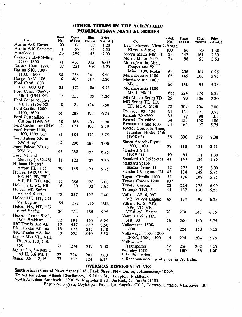
OTHER TITLES IN THE SCIENTIFIC
PUBUCATIONS BNUAI SERIES
Bool Pag s IDo Price Book Pages Dlus Price
Car No of Text Indiom Aus t Car No of Text trntiollS AusLt
Austin A40 Devon 00 106 89 120 Lawn Mowers Vieta 2 Stroke
Austin A40 Somerset 1 99 84 2 30 Kirby 4 Stroke 100 80 89 140
A utoServ I 50 294 48 7 00 Morris Minor MM II 23 142 161 2 30
Complete BMC Mini Morris Minor 1000 24 96 96 350
1100 1800 7L 431 315 9 00 Morris Austin Mini
Datsun 1000 1200 87 224 208 6 25 Cooper and S
Datsun 510 1300 Mini 1100 Moke 64 236 187 6 25
1400 1600 88 256 241 6 50 Morris Austin 1100 65 145 106 5 75
Dodge ASM 106 6 464 517 2 80 Morris Austin 1800
Ford Capri 1600 Mk I 66 138 95 5 75
and 1600 GT 82 173 108 5 75 Morris Austin 1800
Ford ConsulZephyr Mk I Mk II 66a 224 174 6 25
Mk I 1951 55 7 153 85 120 MG Midget Series TO 29 90 106 230Ford ConsulZephyr MG Series TC TD
Mk II 1956 62 8 184 124 350 TF MGA MGB 70 304 204 7 00Ford Cortina 1200 Peugeot 403 404 31 121 171 3 75
1500 1600 68 288 192 6 25 Renault 750f760 33 79 98 100Ford Customline Renault Dauphine 34 133 158 4 00
Custom 1949 54 10 166 193 120 Renault R8 and RIO 74 164 97 5 75Ford Customline OHV 9 121 107 3 50 Rootes Group HillmanFord Escort I 100 Humber Husky Cob
BOO 1300 GT 81 184 172 5 75 1958 66 36 390 399 7 00Ford Falcon XK to Simca Aronde ElyseeXW 6 cyl 62 290 188 7 00Ford Falcon XR to
1200 1300 37 113 121 3 75
XW V8 63 238 155 6 25Standard 8 14
Ford V8 and1939 46 40 81 51 100
Mercury 1932 48 11 122 132 3 50Standard 10 1955 58 41 147 134 175
Hillman HunlerStandard Space
Arrow HB HC 79 188 121 5 75master Series 11 42 125 105 3 00
Holden 1948 53 FJStandard Vanguard III 43 184 149 5 75
FE FC FB EK Toyota Corolla 1100 73 176 107 5 75
EH EJ HD HR 67 286 128 7 00 Toyota Corolla 1200 93
Holden FE FC FB 16 80 82 185 Toyota Corona 83 224 175 6 00
Holden HI Series Triumph TR2 3 4 44 167 130 5 25
V8 and 6 cyt 75 287 197 7 00 Valiant AP 6 VC
Holden HK HT HG VE VF V8 Engine 69 174 95 6 25
V8 Engine 85 272 215 7 00 Valiant R S AP5
Holden HK HT HG AP6 VC VE
6 cyl Engine 86 224 188 6 25 VF 6 cy Engine 78 279 145 6 25
Holden Torana S SL Vauxhall Viva HA
1969 Brabham 72 191 120 6 25 HB 90 76 200 140 5 75
HC Trucks AR AL 17 437 657 3 50 Volkswagen 1500
IHC Trucks AS line 18 173 245 140 1600 47 224 160 6 25
IHC Trucks AA line 19 595 1040 3 50 Volkswagen 1100 1200
Jaguar Mks VII VIII 1200A 1300 1500 46 224 204 6 25
IX XK 20 140 Volkswagen150 21 274 237 7 00 Transporter 48 256 202 6 25
Jaguar 24 34 Mks I Wolseley 1500 49 100 66 100
and II 3 8 Mk II 22 274 281 7 00 In Production
Jaguar 3 8 4 2 E 77 202 124 6 25 t Recommended retail price in Australia
OVERSFAS REPRESENTATIVES
South Africa Central News Agency Ltd Laub Street New Centre Johannesburg 10799
United Kingdom Alltech Distributors 15 High St Hampton Middlesex
North America Autobooks 2900 W Magnolia BlvdBurbank California 91503
Repco Auto Parts Doylestown Penn Ios Angeles Calif Toronto Ontario Vancouver Be

Type
Bore
StrokeAIO engine
A 12 engine
CapacityAI0 engine
A12 engine
Compression ratio
AIO engineA 12 engine
Bhp Maximum
AIO engineA 12 engine
Maximum torqueA I 0 engine
A 12 engine
Firing order
Idling speed
CYLINDER HEAD
TypeGasket face distortion limit
Valve seat materialInlet
Exhaust
Valve seat insert recess diameter
in headInlet standard insert
Inlet replacement insert
Exhaust standard insert
Exhaust replacement insert
Cylinder head bore diameter for valve
guidetandard guide
ENGINESPECIFIC TIO S
4 cylinder in
line OHV73mm
2 874 in
59mm2323 in
70mm2 756 in
988 cm360 3 in31171 em
715 in3
8 5 I
9 0 1
56 at 6000 rpm68 at 6000 rpm
8 50 kg m
@ 4000 rpm615 ft lb
@4000 rpm9 70 kg m
@ 3600 rpm
70 1 ft lb
@ 3600 rpm1 3 4 2
600 rp
Aluminium alloyO IOmm
0 004 in
AluminiumbronzeCast iron
37 016 37 00 mm
14573 14567 in
37 516 37 50 mm
14770 14763 in
33 016 33 00 mm
12998 1 2992 in
33 516 3350 mm
13195 13190 in
12 011 12 00 mm
04728 04724 in
Replacement guide 12 211 12 200 mm
04807 04800 in
450Valve seat angleValve seat width
Inlet 130 mm
0 0512 in
1 80mm
0 p709 inExhaust
Valve seat insert outer diameter
standardInlet 37 080 37 096 mm
I 459 1460 iri33 080 33 096 mm
1302 1303 inExhaust
Valve seat insert inner diameter
Inlet
Exhaust
30 to 1O mm
1181 to 004in
26mm1023 in
6 0 5 90 mm
02362 0 2323 in
0 064 0 096 mm
0 0025 0 0038 in
VALVES GUIDES AND SPRINGS
Valve seat insert depthInlet and exhaust
Insert interference fit in head
Valves
Head diameter inlet 35mm
1378 in
29mm
0 142 in
8 70 8 69 mm
03426 03430 in
103 5 104 1 mm
4 0750 4 0984 in
0 015 0 045 mm
0 0006 0 0018 in
0 040 0 070 mm
0 0016 0 0028 in
exhaust
Stem diameter
Overall length
Stem to guide clearanceInlet
Exhaust
Valve liftA10 engine 7 80 mm
03071 in
750 mm
0 2953 inA 12 engine
Valve guideInner diameter 8 015 8 000 mm
0 3155 03150 in
12 044 12 033 mm
04740 04737 in
0 022 0 044 mm
0 0009 0 0017 in
53mm2 087 in
Outside diameter
Interference fit in head
Length
7

2 Engine
Fitted height above spring seat
Valve springFree length
Fitted length and load
Number ofeffective coilsWire diameter
Coil diameter
Rocker arm to valve stem clearanceHot
18mm0 709 in
45 7 mm
I 7992 in
38 5 mm
@ 30 0 kg1 516 in
@66 llb4 5
4 276 mm
0 1693 in
26 224 mm
0 0324 in
03 5 mm
0 0138 in
0 25 mm
0 0098 in
PISTONS PISTON RINGS AND GUDGEON PINS
Cold
Pistons
Type
Piston fitSkirt diameter standard
I t oversize 25 mm
2nd oversize 50 mm
3rd oversize 75 mm
4th oversize 100 nun
5 th oversize 125 mm
6th oversize 150nun
Piston to cylinder bore clearance
Piston ringsWidth compression
oil con trol
Side clea ance in grpove
Ung gap
GUDGEON PIN
Gudgeon pinDiame er
Slipper skirtcast aluqliniumalloySelective72967 73 0 7 nun
2 8727 2 8747 in
73 217 73267 nun
2 8826 2 8845 in
73 467 73 517 mm
2 8924 2 8944 in
73 717 73 767 nun
29022 2 9042 in
73 967 74 017 riun
2 9121 2 9140 in
74 217 74 297 nun
2 92 19 2 9239 in
74467 74 517 nun
2 9318 2 9337 in
0 023 0 043 nun
0 0009 0 0017 in
2 00 mm
0 0787 in
4 00 mm
0 1575 in
0 04 0 07 mm
0 0016 0 0027 in
0 20 030 mm
0 0079 0 0ll8 in
17447 17452mm0 6869 0 6871 in
Clearance in piston 0 006 0 008 mm
10 0002 0 0003 in
Interference fit in connecting rod 0 017 0 034 mm
0 0007 0 0013 in
Length 65 23 6548 mm
2 5681 2 5779 in
With pistolJ at a temperature of 200C 680F
CRANSHAFT AND MAIN BEARINGS
CrankshaftMain journal diamet r 49 964 49 957 mm
I 9671 1 9668 in
0 03 mm
00012 in
0 020 0062 nun
0 0008 0 0024 in
0 5mm
0 0059 in
0 015 0 050 nun
10 0006 00020 in
0 05 0 15 mm
0 0020 0 0059 in
030 mm
0 0118 in
1835 1 827 mm
0 0722 0 0719 in
44 974 44 961 mm
I 7706 1 7701 in
0 03 mm
0 0012 in
CONNECTING ROD AND BIG END BEARING
Journal taper or ovality wear limit
Main bering clear ce
Clearance wearl it
CrankShaft run out
End float
End float wear limit
Main bearing thickness
rankpin diameter
Crankpin taper or ovality wear limit
Connecting rod
Lergth A 10 engine 116 97 117 3 mm
4 9051 4 6188 in
12147 12153 mm
4 7822 4 7846 in
1 500 1 508 mm
0 0591 0 0594 in
0 20 030 mm
0 0079 0 0012 in
040 mm
0016 in
0020 0 050 mm
0 0008 0 0020 in
0 05 010 mrn
00020 0 0039 in
CAMSHAFT AND BEARINGS
AI2 engine
Big end bearing thickness
Big end end float
End float wear limit
Big end bearing clearance on
crankpin
Connec ing rod bent or misalignment
Camshaft bearing journal diameter
No 43 79343 806 mm
I 7241 1 7246 in
43 283 43 296 mm
17040 1 7046 inNo 2
8

No 3
No 4
No 5
Camshaft run out
Journal to bearing clearance
Bearing inner diameter
No 1
No 2
No 3
No 4
No 5
LUBRICATION
TypeOil pump type
Filter typeOil pump
Side clearance inner and outer
rotors
Clearance outer rotor and body
Clearance rotor to end cover
Relief valve springFree leilgth
Fitted length
Reliefpressure
42 78342 796 mm
1 6844 16849 IiI42 283 42 296 rom
I 6647 16652 in
41218 41231 mm
16228 16233 in
0 61 0 IOmm
0 0004 0 0039 in
0 024 0 065 mm
0 0009 0 0026 in
43 843 43 833 mm
17261 17257 in
43333 43323 mm
I 7060 1 7050 in
42 846 42 836 mm
1 6868 16865 in
42333 42 323 nim
1 6667 16663 in
41268 41258 mm
1 6247 1 6243 in
Full pressureEccentric motor
trochoidFull flow
0 65 0 12 mm
0 0020 0 6047 in
0 15 0 21 mm
0 0059 0 0083 in
0 12mm0 0492 in
4349 mm
I 71 in
3030 mm
I 19 in
3 80 4 26 kg cm254 0 59 70 psi
Engine3
CapacityWith new filter 3 20 litre
2 75 Imp qts337 US qts
2 70 litre
237 Imp qts2 87 US qts
Less filter
TORQUE WRENCH SETTING MAXIMUM
Comiecting rod nuts 3 6 kg m
26 ft lb
Cylinder head bolts 4 80 kg m
34 70 ft lb
Flywheel boltsA10 engine 3 00 kg in
7 50 ft lb
Al2 engine 7 50 kg m
5420 tt lb
Main bearing cap bolts 530 kg m
3830 ftlb
Camshaft sprocket bolt 4 50 kg m
3250 ft lb
Camshaft locating plate bolts 0 50 kg m
3 60 ft lb
Sump bol ts 0 60 kg in430 ft lb
Oil pump attachment bolis 1 50 kg m
I0 80 ft lb
Oil strainer bolts 1 40 kg in
10 10 ft tb
Crankshaft pulley bolt 16kg m
116 ft lb
Timing chain tensioner bolts 0 80 klilm5 80 ft lb
Rocker pedestal bolts 2 50 kg m
I 8 10 ft lb
Mainfolct bolts 1 40kg ni
10 10 ft lb
Pump release valve plug 5 00 kg in36 20 ft lb
t
I DESRIPilON
The four cylinder overhead valve engine has a cast iron the comi cting rod and this is the only means ofretaining the
alloy cylinder block and crankcase The cylinder head is of gudgeon pin in the assemblycast aluminium alloy with replaceable valve guides Each The crankshaft is counter balanced and funs in three
valve has its individual port and is operated by a tappet push AIO or five AI2 steel backed copper lead split shell
rod and rocker arm from the camshaft main bearings Crankshaft end float is taken at the centre
main bearingConnectirig rod big end bearings are split steel backed
copper lead replaceable shellsPistons are marked on the crown with a code number of
the cylinder bore size which must be to the front of the
engine
Pistons are slipper skirt aluminium alloy type with two
compression rings and orie oil ring The lower compressionring is taper faced and t e oil ring comprises an upper and
lower chrome faced steel segment with a spacer in between
The gudgeon pin is an interference fit in the smail end of
9

4lEngine
I
Driven Side View of 1000 Series Engine and Automatic Transmission
Typical Also of 1200 Series
Connecting rods and big end bearing caps are numbered
The big ends of the connecting rods are bored with an oil
squirt hole on the thrust side
The oil pump is the trocoid gear or internal rotor typeand is driven by the camshaft to provide full pressure to the
engineOil passes through a drilling to thecentre rocker pedestal
to provide lubrication to the rocker armSand shaft
Oil pressure is maintained at a pre detennined maximum
by a spring loaded relief valve situated within the pump
body
The lubricating oil passes through a full flow oil filter
moun ted externally on the oil pump
TO REMOVE AND INSTAL
2 E mNE AND TRANSMISSION
1 Drain the cooling system and the gearbox2 Disconnect the battery leads at the battery and
remove the battery and battery Hay3 Release the retaining clips and remove the upper and
lower radiator hoses Remove the air cleaner4 Where fitted release the retaining clips and
disconnect the heaterhoses at the engine5 Disconnect the high and low tension leads at the coil
and distributor6 Disconnect the alternator leads at the alternator and
the starter leads at the starter solenoid
7 Disconnect the oil gauge and temperature gaugewires at the engne
8 Disconnect the choke and throttle con rrollinkage at
the carburettor9 Disconnect the fuel inlet pipe at the fuel pump
10 Remove the flange nuts and disconnect the exhaustoutletpipe at the manifold
11 Raise the car sufficiently take out the split pins
and disconnect the gear change links at the levers on the side
of the gearbox12 Unscrew the ferrule and disconnect the
speedometer drive cable assembly at the gearbox rear
extension
13 Disconnect the earth strap at the starter motor
mountingbolt14 Disconnect the handbrake rod support on the
gearbox15 Take out the four bolts disconnect the rear
universal joint flange from the pinion flange at the rear and
withuraw the pC0peller shaft from the rear ufthc gearboxt 16 1000 model Slacken the lock nut at the adjuster
endof the clutch control cable and unscrew the cable adjusterbolt from the end of the cable 1200 model Slacken the
adjustment at the upper end ofth cable case and unhook the
lower end of the cable offthe clutch release throwout lever
17 Remove clutch cable casing bracket attaching bolt
and withdraw the cable and bracket clear of the engine and
gearbox assembly18 On models with hvdraulic clutch operation
10

disconnect the flexible hose at the slave cylinder and plugboth the hose and the cylinder connection to prevent entry of
dirt
19 Take out the four securing bolts and remove the
radiator
20 Using suitable lifting tackle attached to the liftingbrackets on the engine tighten the lifting gear to take the
weight ofthe engine assembly21 Remove the nuts securing the front engine
mountings take out the two bolts attaching the rear enginemounting to the rear extension housing take out the two
Engine5
bolts attaching the mounting bracket to the underframe and
remove the rear mountingassemble22 Raise the engine tilting it upwards sharplv at the
front and lift it from the car through the bonnet openingInstallation is a reversal of the removal procedure with
attention to the following pointsAIlOw the weight of the engine to settle on the front
engine mounting before tightening the mounting n11ts
Fill the gearbox with the correct grade and quantity of
oil
frEnsure that there are no water leaks
TO REMOVE AND DISMANTLE
1 ROCKERinMS AND SHAFII
1 Remove the air cleaner and the pipe from the air
cleaner to the rocker cover
2 Take out the screws and lift off the rocker cover and
remove the cork gasket3 Unscrew the five rocker pedestal bolts progressively
loosening eacn bolt a few turns at a time until they are all free
and lift offthe rocker assembly4 Remove the bolts from the rocker pedestals starting
at the rear and withdraw the rear pedestal rocker armspringrocker arm pedestal in that order noting any spacer washers
interposed between the rocker arms and the adjacentpedestaL
NOTE Keep each component in the order ofdismantling so
that it can be assembled in the original position This is
important as the rocker arms are offset with the adjustingscrew end towards the adjacen tpedestal
TO ASSEMBLE AND INSTAL
1 Check each rocker armand the rocker shaft for wear
Check that the oil holes and passages in the rocker arms are
clean and free ofany sludge or scale2 Position the front rocker pedestal on the front end
of the shaft and insert the pedestal bol t to hold it in position3 Instal a spacer washer if fitted followed by the
front rocker ann spring rocker ann washer and the second
pedestal push the pedestal along the shaft compressing the
spring unttl the pedestal bolt can be inserted to hold the
assembly in position
t
Vi i
4 Continue to reassemble the remaining componentsiitilthe rear pedestal has been installed and retained in
position by inserting the securing bolt
NOTE If the rockershaft is correctly assembled each rocker
arm vfiu be offset with the adjuster screw end of the rocker
towards the adjacent pedestal
5 Place the rocker assembly on the cylinder head and
screw the securing bolts into the head until they are fingertight Ensure that the ball end ofeach rocker adjusting screw
is seated correctly in the socket end ofits push rod
6 Using a suitable spanner tighten each pedestalsecuring bolt progressively a few turns ach until the five
pedestals are seating securely on the cytlnder head Use care
to ensure that the centre pedestal is located correctly on the
oil passage in the cylinder head
7 Tighten the rocker pedestal securing bolts to the
specified torque8 Check the rocker arm to valve stem clearance and
adjust if necessary as described in TO ADJUST VALVE
CLEARANCE9 Using a new gasket place the rocker cover on the
cylinder head with the oil filler cap to the front instal the six
securing screws firmly but do notover tighten or the cover
flange will become distorted
10 Position the air cleaner on the carbureltor and
secure with clamp and wing nut Using suitable pliers to
expand the clips connect the pipe between the aircleaner and
the rocker cover
r
U
Rocker and Shaft Assembly Note Offset of Rocker Screws
11

6Engine
4 Cl LI DER UKD
TO REMOVE
I Remove the air cleaner and the pipe from the air
cleaner to the rocker cover
2 Drain the cooling system at the two drain cocks one
on the rear ofthe lower radiator tank and the other on the left
hand side of the engine towards the rear
NOTE Ifanti freeze mixture is beingused drain intoa dean
container to be usedagain
3 Disconnect the earth cable at the battery tenninal4 Slacken both hose clips and remove the upper
radiator hose between the radiator and the thermostat
housing5 Disconnect the fuel feed pipe at the carburettor and
the fuel pump release the fuel pipe from the steady clip on
the front of the cylinder head and remove the pipe from the
engine6 Disconnect the vacuum advance pipe from the
RINGSEU
A
COTTERS
bCOTTERS
9 SPRING eN
AINLET VALVE SEAL
IOsEAT WASHERS
q4HLET VALVE
I
1EXHAUST VALVE
Valve and Valve Spring Companenu
carburettor and distributorand remove from theengine7 Disconnect the high tension leads at the spark plugs
and coil and remove the distributor cap and leads Remove
the spark plugs from the cylinder head8 Disconnect the temperature gauge wire at the
connection on the front of the cylinder head
9 rake out the six securing screws and remove the
rocker cover and gasket from the cylinder head
10 Progressively loosen the rocker pedestal securingbolts a few turns at a time until they can be fully unscrewed
with the fingers Do not remove the bolts from the pedestalsand shaft as they will serve to retain the rocker componentson the shaft Remove the rocker and shaft assembly from the
cylinder headII Withdraw the push rods keeping them in order of
removal to ensure installation in the original positions12 Remove the nuts and washe and remove the inlet
and exhaust manifold assembly Remove and discard the
manifold gasket13 Unscrew and remove the cylinder head bolts in the
reverse order of tightening see illustration Note that the
cylinder head bolt removed from the centrehole on the righthand side is marked with aT on the bolt head
14 Lift off the cylinder head and gasket Discard the
gasket
TO DISMANTLE
1 Place the cylinder head on its edge on a bench and
using a suitable valve spring compressor compress each valve
spring in turn remove the O ring seal and split retainingwllets
2 Release the spring compressor and remove the valve
spring retaining cap spring and spring seat washer if fitted
3 Check the end ofthe valves for bur and upsettingcaused by slack adjustment and ifnecessary clean up with a
smooth file
4 Withdraw the valves keeping them in order so that
EXHAUST VALVES
LLJI J JL
INLET VALVES
Combustion Chamber Side of Cylinder Head
12

Engine7
7
e
Sequence fr Tightening Cylinder Head Its Loosen in Reverse Order
they can be reassembled in the original positions Jlt surface ground to bring the head back to a serviceable
5 Pull the shroud type neoprene seal offthe end ofthe conditioninlet valve guide and discard if they have been in service for a 7 With a valve spring tester check the valve springconsiderable time Note that the shroud type seal is retained tensions and lengths see Specifications If a valve springon the endof the guide by a spring ring tester is unavailable then the test can be made by comparing
the used springs with a new springAlso check the valve springs for squarenessTOCHECK AND INSPECT
I Clean the valves thoroughly of carbon deposit and
discard any valve that is cracked or burnt
2 Reface each valve face to the recommended angle as
shown in the specifications and each valve stem flat and true
on a suitable valve eefacing machine Discard any valve tha t
proves to be excessively bent
If a valve head has been reduced to 0 50 mm 0 020 in or
less after the grinding operation then the valve concerned
should be renewed
Valve stem ends may only be reduced up to 0 50 mm
0 020 in
3 Measure the valve stem outer diameter and the valve
guide inner diameter to calculate the actual valve stem to
guide clearance If clearance is in excess of the limit of 0 1
mm 0 004 in then the valve guides and or valves should be
renewed4 Remove the carbon deposits from the cylinder head
face and the valve throats and check the conditions of the
valve se ts
Ifnecessary recut the seats with a valve seat cutter to the
recommended angle and wid tho
NOTE If the seats in the head are worn or recessed
excessively then new inserts will have to be installed It is
recommended that the installation of new valve inserts
and or valve guides if necessary be entmsted to an
automotive engine reconditioner who has the necessarv
specialised equipment to carry out these operations
5 Lap the valves to the valve seats with a lappingcompound Apply a smear ofPruss ion blue to the valves after
lapping and check the valves on their respective seats to
ensure that a true and concentric seating has been gained6 With a steel straight edge and feeler gauge check the
cylinder head face for warping If the cylinder head is found
to be warped in excess of the limit specified see
Specifications then it will be necessary to have the head
TO RENEW V ALVEGUIDES
I Using a suitable pilot drift drive the worn valve
guides out of the cylinder head towards the combustion
chamber2 Clean the area in and around the guide position in
the cylinder head and wipe clean
3 Warm the cylinder head up to a temperature of
2000C 3920F lightly oil the lower end of the new guideand using the shouldered drift drive the new guide into
position so that it stands proud ofthe valve spring seat by the
specified amount See Specifications
NOTE The internal bore of the exhaust valve guide is
counter bored at its combustion chamber end Ensure that
this end of the guide enters the cvlinder headfirst
4 Check the fit of the valve in the new valve guide and
if necessary ream the guide to the specified diameter
5 After the new guide has been fitted and ifnecessaryreamed to size reface the valve seat using a vibro centric or
suitable tool to ensure that the valve seat is true and
concentric with bore axis of the valve guide This is most
important to ensure that the valve seatscorrectly
TOCHECK VALVE SPRING
I Check the valve spring free length and length under
load2 Check that the springs are not bent or distorted from
heat
If a spring tester is not available check the springs bycomparison with new springs This can be done by using a
surface plate and straight edge for checking free length and byusing a new spring and a used spring loaded in a vice end on
end with a plate in between Measure from the plate to the
vice jaw adjacent to both the new and used springs
13

sEngine
A used spring is serviceable if1t does not show collapse in
excess aftive percent when subjected to this comparison test
TO ASSEMBLE
1 Before assembling the cylinder head ensUre that all
traces of emery dust or grinding paste are removed from the
valv seats and ports and apply a light coating of oil to the
seats and the valve guides2 Oil the valve items and instal all eight valves ensuring
that each valve is installed in the position from which it was
remQved3 On inlet valves instal a new shroud type seal on
each valve stem and secure on the valve guide upper end byfitting the spring ring
4 Instal a valve spring seat washer valve spring and
spri g retaining cap5 Using a suitable spring compressor compress the
spritig and fit the split retaining collets in the recess in the
end of the valve stem Hold the collets in position and
carefully release and remove the spring compressor Ensure
that the collets are correctly seated in the spring retainingcap y tapping on the end of the valve stem with the end of
a hammer handle6 Oil a new Oring seal and instal it in the receSS in
the spring retaining cap above the split collets Assemble
the remaining valves in a similar manner
TO INSTAL
I Ensure that the gasket faces of the cylinder block
and the cylinder head are perfectly clean and free of any
burrs or pieces of the old gasket2 Place the new gasket in position on the cylinder
block face and ensure that all bolt and water circulation
holes register If available screw a guide pin into one of the
hold down bolts holes at each end of the cylinder block
face
NOTE The cylinder head gasket is marked TOP to
acilftate co ectassembly
3 Lower the cylinder head into position and instal
seveal of the cylinder head bolts finger tight4 Remove the two guide pins if used and instal the
remmnder of the cylinder head bolts finger tight
NOTE One of rhe cylinder head bolts is marked wirh a
r on the bolt head This bolt must be installed at the
centre hole position on the right hand side of rhe engine
5 Using a suitable torque wrench tighten the
cyli det head bolts evenly and progressively to the specifiedtightening figure See Specifications in the order shown
in the illustration
6 Instal the push rods ensuring that each is replaced
in the location from which it was removed and that each
rod seats correctly in its tappet7 Position the rocker shaft and tocker ann assembly
on the cylinder head and instal the rocker pedestal securingbolts finger tight
8 Tighten the rocker pedestal bolts a few turns at a
time evenly and progressively to the specified torque see
Specifications9 Turn the engine crankshaft in the direction of
normal totation until each valve tappet is exactly on the
heel of its cam and adjust the clearance between the tocket
arm and the valve stem See Specifications This is a
starting point for valve adjustment and the c1eatance should
be ch cked wheQ the engine is at normal opetatingtemperature
10 Refit the inlet and exhaust manifolds using a new
manifold gasket and temporarily fit the r ket cover and
gasket11 Connect the fuel delivery pipe between the
catbureltot and the fuel pump and the vacuum advance
pipe between the distributot and the catbureltor
12 Clean adjust and instal the spark plugs fit the
distributor cap and connect the high tension leads to the
spark plugs and the ignition coil
13 Connect the wire to the tempetature gauge sender
unit on the front ofthe cylinder head
14 Instal the upper tadiator hose and secure with the
two hose clips15 Fill the cooling system with clean water if
necessary using the water and anti freeze mixture drained
from the engine previouslyI6 Connect the earth lead to the battery tenninal
start the engine and bring it to nonnal operatingtemperature switch off the engine remove the rocker cover
and check and if necessary adjust the rocker to valve stem
cleatance see Specifications17 Re instal the rocker cover and tighten the six
screws securely18 Instthe ait cleaner and pipe from the cleaner to
the rocker cover start the engine and run to check for oil
leaks
TO ADJUST VALVE CLEARANCE
I Run the engine at a fast idle speed until it has
attained the normal operating temperature2 Remove the air cleaner and rocker covet
3 Turn the crankshaft in the normal direction of
rotation until No I cylinder is at tde on the compressionstroke and adjust both rocker anns to give the specifiedrocker to valve stem clearance
4 Using the same procedure fot the remaining three
cylinders adjust the other six tockers
5 To check the adjustment turn the crankshaft until
one valve is fully open then turn a fUtther one completeturn and check the clearance for this valve Check the
remaining valves in the same manner
6 Refit the rocker cover and air cleaner
14

Engin 9
TO REMOVE AND INSTAL
d ENGINE SUMP
I With the engine removed from the vehicle removethe drain plug and drain the oil into a suitable container
Replace and tighten the plug2 Progressively loosen and remove all the bolts and
spring washers securing the slimp to the crankcase
3 Remove the sump lifting it clear of the oil intake
strainer Remove the side gasket and the end seals around
the rear bearing cap and the lower edge of the timing cover
and discard J
4 Clean the sump thoroughly ensuring that all traces
of the old gasket are removed5 Clean the gasket face of the crankcase and the end
seals ensuring that all traces o the old gasket are removed
6 Using a small quaniity of suitable sealingcompound position a new gasket on the crankcase face of
the cylinder block
NOTE With new cork gaskets that appear to be too small
or have shrunk a few minutes immersed in water will
restore them to their norma length
7 Place the end seals in position and ensure that the
ends of the seals mate with the ends of the side gasket to
form an oil tight joint8 Carefully place the sump in position on the gaskets
and instal two or three sump retaining bolts to hold it in
position9 Instal the remainder of the bolts and tighten finger
tight10 Using a suitable sockei wrench tighten the bolts
evenly and progressively a few tums each to pull the sumpup firmly against the gasket Do not over tighten the bolts
or the flange on the sump will be distorted Ensure that the
drain plug is tight before filling with oil
TO REMOVE
6 TIMiNG HAIN AND ieUV K
1 vlith the engine rerrloved from the vehicle remove
the water pump and fan assembly2 Take out the retaining bolt and washer and
withdraw the crankshaft pulley3 Removeihe sump drain plug drain the oil into a
suitable container and remove the sump
Timing Cover showing Timing Chain Damper Pad
4 Remove the remaining bol ts and washers and
withdrathe timing chain cover from the front of the
engine Remove the oil slinger if fitted from the front end
of the crankshafi5 Unscrew the two bolts securing the chain tensioner
to the front of the cylinder block and remove the chain
tehsioner B
NOTE Use care when removing the tensioneras the padand stem will be forced out of the tensioner body by the
spring when the bolts aremoved
6 Rotate the crankshaft until the sprocket key is at 4
o clock and the timing mark on the crankshaft sprocket is
adjacent to the marked link plate on the chain The other
marked link plate on the chain will be at approximately12 15 clock and adjacent to the timing mark dimple on
the camshaft sprocket7 Remove the camshaft sprocket retaining bolt and
washers and using a suitable lever prise the sprocket off
the camshaft from the top and remove the sprocket and
chain disengaging the chain from around ihe crankshaft
sprocket
TO INSTAL
1 Clean all components and remove all traces of the
old gasket from the timing cover waier pump body and
sump2 Check and if necessary rotate the camshaft until
the sprocket locating dowel is at the 4 0 clock position in
relation to the centre of the camshaft
3 Check and if necessary rotate the crankshaft until
the sprocket drive key in the shaft is at 4 0 clock position
15

lQEngine
Showing Wear Limit for Timing Chain Stretch and
Tensioner Pad Wear
in relation to the centre of the crankshaft
4 With the camshaft and crankshaft positioned as in
i and 3 above a line drawn through the centre of each
shaft will also pass through the centre of the camshaft
dowei and the crankshaft key5 uy the camshaft sprocket flat on a bench with the
timing mark dimple to the top arid facing up The locatingdowel hole will be at 4 0 clock
6 Loop the timing chain on the camshaft sprocket so
that one of the two marked link plates of the chain engagesthe sprocket adjacen t to the sprocket timing mark dimpleThe second marked chain link plate must be to the right on
the short chain run
SPROCKET
RETAINING WASHER
BOLT
t
4RETAIDlER PLATE
1SPRING WASHER
TIMING CHAIN
TENSIONER BODY
fENSIONER SPRING 0
SUPPER HEAD
WASHER
Camshaft and Timing Chain Components
NOTE The liming clwill lillk plale marks circles are rell
plates apart on the shortest chain run This includes the
marked plates
7 Grasp the camshaft sprocker engaged in the chain
and position it on the camshaft looping the chain around
the crankshaft sprocket so that the second mark circle on
the chain link is adjacent to the timing mark dimple on
the crankshaft sprocket see illustration
8 Push the camshaft sprocket on to fully engage the
locating dowel lnstal the securing bolt and washers and
tighten to the specified torque see Specifications9 Check that both sprocket and chain timing minks
register for correct valve timing10 Instal the chairi tensioner on the front face of the
cylinder block ensuring that the long end of the slipper padis to the camshaft sprocket
II Check that the side tensioner pad in the timingcover is serviceable and renew if excessively worn
12 Instal a new oil seal in the timing cover with the
lipped face of the seal towards the timing sprocket Instal
the oil slinger if fitted with the concave face towards the
crankshaft pulleyi 3 Further installation is a reversal of the removal
procedure with attention to the followingFit new gaskets where necessaryDo not over tighten the sump retaining bolts
7 C AMSHAFT ND TAI PETS2 Evenly and progressively loosen the rocker pedestal
securing bolts and remove the rocker arm and shaft
assembly3 Take out the retaining bolt and withdraw the
crankshaft pulley
TO REMOVE
I With the engine removed from the vehicle remove
the water pump and fan assembly and take off the rocker
cover
16

r
Checking Camshaft End Float
4 Drain the engine oil and remove the sump5 Take oui the remaining bolts and withdraw the
timing chain cover from the front of the engine Remove
tlie oil Slinger from the front end of the crankshaft6 Unscrew the two bolts securing the chain tensioner
to the front of the cylinder block and remove the chaintensioner
NOTE Use care when removing the tensioner as the padand stem will be forced out of the tensioner bodv bv the
spring when the boltsare removed
7 Remove the eamshaft sprocket retaining bolt andwashers and using a suitable lever prise the sprocket offthe camshaft from the top and remove the sprocket and
chain disengaging the chain from around the crankshaft
sprocket8 Turn the engine so that the crankshaft is
Enginell
uppermost and press each tappet down well clear of the
camshaft9 Disconnect the fuel delivery pipe at the fuel pump
take out the two bolts and remove the fuel pump from the
right hand side of the engine
10 Remove the distributor cap and high tension
leads disconnect the vacuum pipe at the vacuum advance
unit
II Unscrew and remove the iwo bolts from the
oistributor retaining plate and withdraw the distributor
from the cylinder block
12 Remove the oil pump and tilter as an assembly byunscrewing the three bolts and withdrawing the assemblyfrom the crankcase
13 Remove the two retaining bolts and washers and
slide the camshaft retaining plate clear of the groove in the
camshaft and remove the plate14 Withdraw the camshaft from the cylinder block
using care not to damage the camshaft bearings with the
sharp sides of the cams Remove the tappets keeping them
in their correct order for reassembly5 Check the camshaft bearings and if worn to
excess using a special screw press remove the worn
bearings and press ne bearings into position Line bore the
new bearing to the cor ect size and fit a new expansionplug using a small quantity of sealing compound in the
end of the rear camshaft bearing bore
TIMING MARKS
A9 tr
r lCAMSHAFT SPROCKET J e i
O
j wf1
17
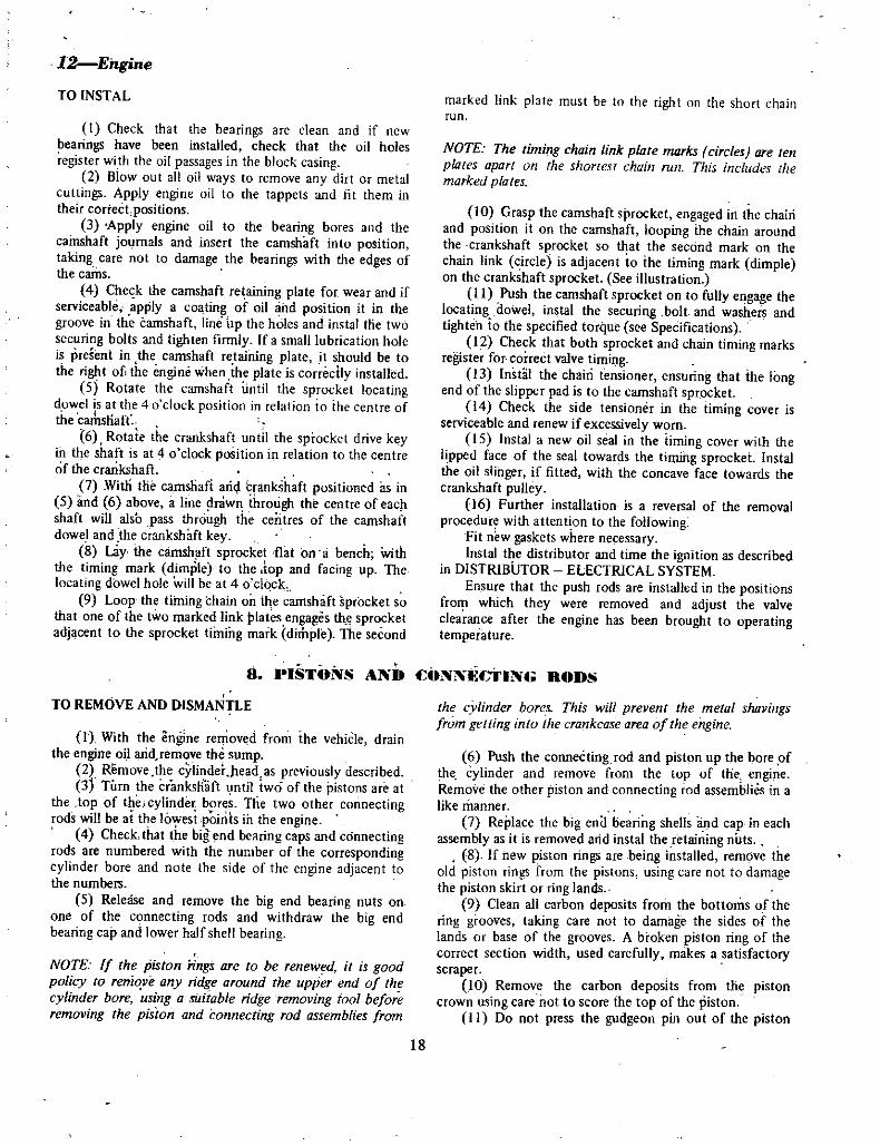
12EngineTO INSTAL
t Check tha t the bearings are clean and if new
bearings have been installed check that the oil holesregister with the oil passages in the block casing
2 Biow out all oil ways to remove any dirt or metal
cuttings Apply engine oil to the tappets and fit them intheir cortect positions
3 Apply engine oil to the bearing bores and thecainshaft jOlJrnals and insert the camshaft into positiontaking care not to damage the bearings with the edges ofthe cams
4 Che k the camshaft retaining plate for wear and ifserviceable apply a coating of oil and position it in thegroove in the camshaft lineup the holes and instal tlie twosecuring bolts and tighten firmly If a small lubrication holeis preSent in the camshaft retaining plate it should be tothe right of the engine when the plate is correctly installed
5 Rotate the camshaft until the sprocket locatingdowel i s at the 4 u clock position in relation io the centre ofthe camsHaft
6 Rotate the crankshaft until the sprocket drive keyii1 tle shaft is at 4 o clock position in relation to the centre
of the crankshaft7 Witli die camshafi aM crankShaft positioned as in
5 and 6 above a line drawn ihrOligh the centre of eac
shaft will also pass through the centres of the camshaftdowel and the crankshaft key
8 Lay the cainsh ft sprocket flat on a bench Withthe timing mark dimple to the top and facing up The
locating dowel hole will be at 4 0 clock9 Loop the timing chain on the camshaft sprocket so
that one of the two marked link plates engages tlce sprocketadjacent to the sprocket timing mark dimple The second
marked link plate must be to the right on the short chainrun
NOTE The timing chain link plate maries circles are ten
plates apart on the shortest chain roll This includes themarked plates
10 Grasp the camshaft sprocket engaged in the chairiand position it on the camshaft looping ine chain aroundthe crankshaft sprocket so that the secdnd mark on thechain link circle is adjacent io ihe timing mark dimpleon the crankshaft sprocket See illustration
11 Push the camshaft sprocket on to fully engage thelocating dowel instal the securing bolt and washers andtighten io the specified torque see Specificationst2 Check that both sprocket and chain timing marks
register for correct valve timi1Jg13 Instlil the chain tensioner ensuring that ille long
end of the slipper pad is to the camshaft sprocket14 Check the side tensioner in the timing cover is
serviceable and renew if excessively worn
15 Instal a new oil seal in the timing cover with the
lipped face of the seal towards the timing sprocket Instalthe oil slinger if fitted with the concave face towards thecrankshaft pulley
16 Further installation is a reversal of the removalprocedure with attention to the following
Fit n wgaskets where ne essaryInstal the distributor and time the ignition as described
in DISTRIBUTOR ELECTRICAL SYSTEMEnsure that the push rods are installed in the positions
from which they were removed and adjust the valveclea ance after the engine has been brought to operatingtemperature
TO REMOVE AND DISMANTLE
8 PISTONS AND CONNECTING RODS
lJ With the engine removed from ihe vehiCle drainthe engine oil aridJemove the sump
2 Remove the cylinder pead as previously described3j Turn the cr mkstfift ntil iwd of the pistons are at
the top of theicylinder bores The two other connectingrods will be ai the lo esipoinls ih the engine
4 Check that the big end bearing caps and connectingrods are numbered with the number of the correspondingcylinder bore and note the side of the engine adjacen t tothe numbers
5 Release and remove the big end bearing nuts on
one of the connecting rods and withdraw the big end
bearing cap and lower half shell bearing
NOTE If the piston iings are to be reneWed it is goodpolicy to remove any ridge around the upper end of the
cylinder bore using a suitable ridge removing tool beforeremoving the piston and connecting rod assemblies from
the cvlinder bore This will prevent the metal shavingsfrom getting into the crankcasearea of the enginc
6 Push the connecting rod and piston up the bore ofthe cylinder and remove from the top of the engineRemove the other piston and connecting rod assemblies in a
like manner7 Replace the big eno liearing shells and cap in each
assembly as it is removed arid instal the retaining nuts8 If new piston rings are being installed remove the
old piston rings from the pistons using care not to damagethe piston skirt or ring lands
9 Clean all carbon deposits from the bottoms of thering grooves taking care not to damage the sides of thelands or base of the grooves A broken piston ring of theCorrect section width used carefully makes a satisfactoryscraper
10 Remove the carbon deposits from the pistoncrown using care not to score the top ofthe piston
II Do not press the gudgeon pin out of the piston
18

and small end of the connecting rod unless one or other ofthe components are to be renewed
NOTE The gudgeon pin is an interference fit in the small
end of the connecting rod and this is the sole means ofretaining the assembly together The gudgeon pin is a
thumb push fit in the piston at normal room temperature
TO FIT NEW PISTON RINGS
1 Wipe the cylinder bores clean and ensure that there
are no traces of carbon or other foreign matter present2 Place a new piston ring in the bore of the cylinder
and using the piston inverted push the piston ring down toa relatively unworn part of the cylinder bore
3 Using a feeler gauge of the correct thickness checkthe gap Ifnecessary adjust the gap by filing to increase the
gap width If the gap is too wide select another ring from
the set If the rings are a matched set adjustment will notbe necessary
4 Treat all piston rings in the same manner andensure that the ring side clearance in the piston groove iswithin the specified limits and that the rings are installed on
the piston for the cylinder to which the rings have beenfitted
NOTE USe a ring expanding tool to fit the rings on the
pistons Fit the rings from the top ofthe piston never over
the skirt
f Lubricate the piston and ring assemblies with
engine oil before fitting in the cylinder bores6 If the compression rings are taper faced they will
be marked Top and this mark must be uppermost when ihe
rings are installed on the pistons
TO REASSEMBLE AND INSTAL
1 With the rings fi tted to the pistons and the pistonand connecting rod assembly adequately lubricated withclean engine oil arrange the piston rings so that the top ringgap will be to the side of the piston directly away from theexhaust valve position
2 Fit the second compression ring with the gap at
1800 to the top ring gap3 Fit the oil ring spacer with the gap to the right side
of the engine and the upper and lower oil ring segmentswith their gaps 1200 either side of the spacer gap
4 Insert the connecting rod into the cylinder borefrom which the assembly was originally removed and usinga suitable ring compressor to compress the rings tap the
assembly iilto the bore using a clean hammer handle untilthe ring compressor is free The size code number and theletter F if shown should be to iheTront
5 Oil the upper half of the big end bearing shell andensure that it is correctly seated in the connecting rod with
tang oUhe bearing shell locating with the recess in the rod6 Pull the connecting rod and piston assembly down
Engine13
TOP RING oSECOND RING OOIL RING SEGMENT OOIL RING EXPANOER
OIL RING SEGMENT0PISTON
CONNECTING ROD
1BOLT
JBEARING CAP
NUT
Piston and Connecting Rod Components
the bore until the big end of the connecting rod engages
squarely with the crankpin7 Oil the lower halfbearing shell and bearing cap and
fit it to the connecting rod Instal the big end nuts fingertight
NOTE Ensure that the number of the bearing cap is
adjacent to the number on the connecting rod and that the
squirt hole in the big end of the connecting rod is to the
right hand side ofthe engine
8 Instal the other piston and connecting rod
assemblies using the same procedure9 J Tighten the big end bearing nuts to the specified
torque See Specifications
19

14Engine
TO CHECK CYLINDER BORES
9 LlNDER BOllES AND PISTONS
DEGlAZING CYLINDER BORES
NOTE To accurately check cvUnder bore condition alld
wear it is essential that all pistons and connecting rod
assemblies be removed from the cylinder block also thataccurate measuring equipment be available to determine theactual cvlinder bore overall wear including taper and
ovality The cylinder boTf s should be wiped thoroughlyclean with a clean rag before checking
I Visually check the bores for cracks flaws scuffingorscoring
2 Check each cylinder bore for wear including taperand ovality
3 Cylinder bores that upon checking prove to be
unserviceable should be rebored and honed to the smallestimmediate oversize and new oversize pistons and ringsfilted
NOTE If it is found that the cylinders leed boring selectthe cylinder with the most wear to detennine whatoversize
pistons aTe to be used Bore all cylinders to that oversize
See Specifications for available oversize pistons
Engines that have been bored to their extreme limit can
be filted with cylinder sleeves which are available in threesizes on outer diameterNew pistons and rings should stillbe filted with sleeves
NOTE Cl lilder bores that are fit for further service withoriginal pistons but require renOnging should be deglazedwith a hone
1 Position plenty of clean rag over the crankshaftand under each cylinder bore to keep abrasive materialsfrom entering the crankcase area
2 De glazing of the cylinder walls may be done byusing a cylinder surfacing hone equipped with 280 gritstones
3 Honing should be carried out by moving the honeup and down the cylinder walls fast enough to achieve a
cross hatch pattern When hone marks interect at 60 degthe Cross hatch angle is most satisfactory for the correct
seating of piston rings
NOTE When deglazing it is important twt only enoughstrokes of the hone are made to eliminate the glazingcondition of the cylinder Excessive honing will increasebore size and thus increase piston skirt clearance
4 Use honing oil which is available from all majordistributors Do not use engine or transmission oil mineralspirits or kerosene
5 After honing it is necessary that the cylinder blockbe thoroughly cleaned to remove all traces of abrasive
Piston and Cylinder Grade Numbers Stamped on Pistons and Top of Cylinder Block
20

i r lW
l
XI I Il i
r0 iiI 11
1
h @ If j 0 t ff I hfi 0 l J I
I r
q i tIl I if
1eo EP II
I
I i 1 l
xs
CA UTlON Be sure that all abrasives are removed from the
engine after honing It is recommended that a solution ofsoap and water be used with a brush and the affectedcomponents thorough y dried
The cylinder bores can be cfmsidered clean when theycan be wiped clean with a white cloth and the cloth remainsclean Smear the bores with engine oil after cleaning to
prevent rusting
CHECKING PISTON SKIRTCLEARANCE
NOTE Cylinders that haye been rebored and honed to takethe appropriate oversize pistons should have each pistonmeasured and then tried in its respective bore with a feelerstrip and spring scale to ensure that correct skirt clearanceis obtained
1 Measure the outside diameter of the piston skirt at
right angles to the gudgeon pin axis and IS 6 mll 0 732 indown from the gudgeon pin centres
The piston temperature when measuring should be
approximately 200C 6S0F2 Select a feeler strip 0 04 mm 0 0016 in in
ISPACER SHIMSfU
EngineIS
thickness and approximately 12 mm 0 50 in in width The
strip should be long enough to extend the full length of the
piston3 Insert the feeler strip into the cylinder bore Invert
the piston and position it into the cylinder bore so that the
feeler strip is located lengthwise between the cylinder wall
and the full length of the piston at 90 degrees to the
gudgeon pin axis
4 Attach a spring scale to the top end of the feeler
strip and withdraw the feeler strip in a plane parallel to the
centre line of the cylinder bore noting the reading on the
spring scale
5 The correct spring scale reading should be within0 2 and 15 kg 0 44 and 330 Ibs If the reading is not
within these specifications then check the originalmeasurements of the piston and bore and also check the
piston skirt for high spots If necessary select measure andcheck another piston to obtain the required fit
6 Follow the same procedure to fit the remainingpistons as required
fio
Q
o
1ll
o 7QH
Underside of Engine with Sump Removed Showing Arrow on Front and Intermediate Main Bearings and Shims behindCrankshaft Sprocket 1000 Series shown 1200 has five Main Bearings
TO REMOVE AND INSTAL
lO CRANKSHAFT NU MAIN HEAIIINGS
1 With the engine removed from the vehicle remove
the rocker mechanism manifold and cylinder head as
previously described2 Remove the sump timing cover timing chain and
sprockets as previously described3 Remove the oil pick up tube and strainer
4 Release the lock plates take out the six securing
bolts and remove the flywheel marking the flywheelposition in relation to the crankshaft flange
5 With the engine inverted and resting on a cleanbench on the cylinder block top gasket surface release the
big end bearing cap nuts and remove the caps and lowerhalf of the bearing shells Keep each cap and shell togetherfor correct installation and note the number on the side ofeach cap
6 Push the connecting rod and piston assemblies
21

16Engine
tFLANGE PLATE
INNER PLATE
Torque Converter Drive Plate to Crankshaft Attachment 1000 Series Automatic
SECURING BOLTS 161
LOCK PLAn 131 O
down the bores towards the top of the block well clear ofthe crankshaft but do not push the pistons out through thetop of the bores Ensure that the upper half of each big end
bearing shell has remained in the connecting rod and is not
sticking to the crankpin7 On the AIO engine release the main bearing cap
bolts and lift off the three main bearing caps andlower half
tF ii
tJ
Rear Main Bearing Oil Sealwith Bearing Cap Removed
bearing shells Keep each cap and shell together for
reassembly On the A12 engine release the main bearingcap bolts and remove the five main bearing caps and lowerhalf bearing shells Keep each cap and shell together forreassembly
NOTE Number the main bearing caps if they are not
already numbered With the exception of the rear main
Checking Crankshaft Endfloat at Centre Main
Bearing on 1000 Model
22

bearing there is an arrow cast in the cap of ail other
bearings which mustpoint to the front of the engine
8 Lift the ctankshaft directly upwards and remove
from the qankcaSe9 Remove the upper half of the main bearings and
keep them together in pairs with each cap for correct
reassembly
NOTE The centre main bearing shells have aflange on each
side to fake crankshaft end thrust
Ins allation is a reversal of the removal procedure with
attention to the following pointsJournals and bearing shells should be checked fat
excessive wear taper or sc ring Bearings that are
unserviceable should be replaced with the appropriateundersize shells and the journal ground to fit
EngineI7
One damaged journal will necessitate the grinding of all
journills and fitting new undersize hearing shells or fitting a
new crankshaft and standard bearings Ensure that the
row on the bearing cap points to the frorit of the engineand the number on the cap coincides with the number on
the crarikcaseConnect up the connecting rod big ends to the
crankpins before tightening the main bearing bolts and thentighten one main bearing to the specified torque followedby rotatilg Jhe crankshaft one or two revolutions to check
forbindirtgIt will be good policy to renew the rear main bearing
oil se l d the seal in the timing cover Instal new gasketsthroughout
It will be necessarY to resei the valve timing on the
timing chain and sprockets check the ignition timing and
adjust rocker to valve stem clearance with the engineinstalled and at working temperature
TO REMOVE AND INSTAL
JI 011PUMP AND FILTER
PLUofiGASKET
VALVE SPRIN V
PRESSURE REGULATOR ALVE Il
Irrch iitlr Y
INNER ROTOR AND SHAFTOSY PASS VALVE
dSPRING
EXPANSION PLUG
1 Grasp the oil filter body firmly turn itanti clockwise and upscrew it off the oil pump body If thefilter is too tight to rotate by hand a special tool isavailable to fit the lower end of t1ie filter body
Take out the three securing screws and withdrawthe oil pump from the right hand side of the crankcase
Installation is a eversa1 ofthe removalprocedure vittiattention to the following points
Use a new gasket 1 etween the pump cover imd thepump body and the body andcrankcase
Tighten the three pump securing bolts to the specifiedtorque see Specifications
Irtstal a new filter if the original unit is not
comparatively ne
Tighten the filter to the pump by hand only Do not
over tighten or leaking may resultEnsure that gasket faces are dean and free of any burrs
TO DISMANTLE AND ASSEMBLE
1 Remove the oil filter take out the tiuee securingbolts and withdraw the pump assembly from the crankcaseDiscard the gasket
2 Unscrew and remove the single bolt attaching the
GASKET
PUMP BODVDRI E GEAR
1lAiifJJ
aja 11 a
RETAINER PIN
Exploded View of Oil Pump Components
body cover to the main body of the pump separate the twoassemblies and discard the gasket
3 Mark the outer end face of the pump outer
trochoid rotor and refl10ve it by tapping the end of the
main body on the bench4 USing a suitable pin punch drive out the pin
securing the pump diive gear 0 the shaft and tap the shaft
and inner rotor out fthe gear and the pump body
NOTE DiJ not remove the inner rotor from the shaftRenew the shaft and inner rotor as an assembly if either are
worn
0
5 Unscrew and remove the screwed plug and gasketand withdraw the pressure relief valve and spring 00 not
lose the adjusting shim between the outer end of the springand the screwed plug
6 Unscrew and remove the pressure gauge sendingunit being careful to avoid damage io the sender element
7 Using a sharp centre punch driven through the
23

18Engine
I
1 t1he I
t tj JS
r
Checking Clearance Between Outer Rotor and Body
expansion plug remove the plug and withdraw the filtetby pass valve spring and ball Disc ttthe expansign Ilug
8 Thoroughly clean all components of the pump andremove all traces ofthe old gaskets from the gasket faces ofthe pump and crankcase
9 Insert the inner rotor and shaft in the pump bodyfit the drive gear and temporarily fit the retaining pin
10 Check the end float of the shaft and rotor in the
body TItis should be a minimUm free fit
1I Apply engine oil to the outer trochoid rotorwith the mark made on dismantling to the top and slide it
into the pump body to mesh with the inner rotor
12 Check the clearance between the outer rotor andthe pump body and also between the highest point of the
inner rotor lobe to the highest point on the outer rotorlobe using feeler gauges of the specified thickness see
SpecificationsIf clearance at these points is in excess
of wear limits renew the pump assembly13 Using a straight edge placed across the ends of the
rotors and the pump body use a feeler gauge to measure
rotor to cover end clearance see Specifications14 f end float of the rotor shaft is excessive remove
the drive gear and instal a suitable spacer shimJ 5 Instal the drive gear and peen the retaining pin
0p
fjL
G e
IiI 1
t
fJS rJr
I
wCftlecking Clearance Between Inner and Outer Rotor lobes
16 Apply engine oil to the inner and outer rotor andinstal the outer rotor
J 7 POsition a new gasket on the cover face of the
pump body and locate it on the cover dowelsJ 8 Place the body cover in position on the main
body to locate on the dowels and instal and tighten the
small securing bolt
19 Place the filter by pass valve ball in positionfollowed by the spring small end first and instal a new
xpansion plug Use a small amount of sealing compoundon the plug to prevent oil leaks
20 Insert the relief valve plain end first in the bore
in the pump body followed by the spring ana any shims
that are fitted Place the shims in the hollow bure of the
retaining plug21 Instal the plug and gasket and tighten securely
l22 Screw the pressure light sender unit into positionin the cover and tighten just sufficiently to prevent any oil
leaks23 Using a new gasket instal the pump assembly on
the crankcase and tighten the three securing bolts to the
specified torque24 Instal the oil filter unit on the pump cover and
tighten by hand only
24

TO REMOVE AND INSTAL FRONT
12 EN INE MOUNTINGS
fJngi 19
I Raise the front of the vehicle and support on
chassis stands2 Remove the bolt nuts fixing the engine mounting
brackets to the front crossmember3 Interpose a wooden block between the engine
sump and a jack and jack up the front of the engineassembly
4 Remove the nuts securing each engine mounting tothe engife ounting brackets and the bolts from the
bracket to the crossmemher5 Remove both front mountings from the brackets
Installation is a reversal of the removal procedureAllow the full weight of the engine assembly to bear on the
mountings before tightening the securing bolts and nuts
TO REMOVE AND INSTAL REAR
I Raise the front of the vehicle and support on
chassis stands
2 Place a jack under the transmission to take the
weight of the engi e and transmission assembly3 Remove the two transmission rear crossmember to
mounting securing bolts4 Remove the bolts which attach the rear
transmission crossmember to the uf derbody an remove
the crossmember
5 Undo the bolts connecting the rear enginemounting to the transmission extension housing and
remove the mountingInstallationis a reversal of the removal procedure
Ensure that the mounting i centralized and that eflgineand tiansm sion weight is aken on the mounting bef9refinally tigjItening the mounting securingbolis
NOTE Engine mountings that are oil soaked should be
renewed and the cause of the oil lea rectified to ensure a
normql working flfe for the mounting concerned
IJ ENGINE FA1JLT DIA NOSIS
I Engine wm not start by normal crankingPossible cause
a Dirty or corroded distributor pointsb Carburettor noodingc Moisture on high tension wires and or inside
distributor capd Dirt or water in carburettor and fuel systeme Incorrectly set spark plug gaps
t Faulty coil or capacitorg Faulty low or high tension wiresh Fuel vapor lock
i Faulty fuel pump
0 Incorrectly set ignition timingk Broken or shortcircuited low tension lead to
distributo points
2 Engine wm not start weak or erratic crankingPossible cause
a Weak or faulty batteryb Fault in starter lead or solenoid
c Faulty starter
3 Engine stalls
RemedvClean or renewand adjust pointsCheck needle valve and noat clean out fuel systemDry out high tension wires and cap
Clean out carburettor and fuel systemReset spark plug gaps to specificationTest and renew faulty componentsTest and renew faulty wires
Check source of vapo lock and insulate a inst heatTest and overhaul fuel pumpCheck and retime ignitionTest and renew lead
Remedv
Recharge or renewbatteryTest and renew faulty componentsTest and overhaul starter
Possible cause Remedya Idling speed set too slow Readjust idling speed stop screw
b Idling mixture too lean or rich Readjust idling mixtur s rew and idling speed screwc Carburettor nooding or noat level incorrectly set Check needle valve r reset noat level
Continued neXl p1ge
25

2QEngine
d ault in coil or apacitore Valve clearance out of adjustmentt Air leak at inlet manifold or carburettor flangeg Carbon tracking or cracked distributor caph Weak or fa lty battery and or corroded terminals
i Carburettor flooding or incorrect float level
setting0 Fauty coil or capaci tor
k Excessive wear in distributor shaft and bushes or
contact breaker earn
I Burned warped or pitted valves
4 Engine missing at idling speedPossible cause
a Dirty defectiJe or incorrectly set spark plugsb Burned or pitted distributor contact pointsc Loose or broken low or high tension wires in
ignition systemd Carburettor idling mixture out of adjustmente Burned or cracked distributor rotor
t Moisture on tigh tension wires spark plug or
distribut1r cap
S Engine mis on accelerati n
Possible cause
a Distributor points dirty or incorrectly adjustedb Spark pluilfs dirty faulty or gap set too widec Dirt or water in carburettor
d Carburettor accelerator pump discharge jetblocked or pump defective
e Coil or capacjtor faultyt Incorrect ignition timingg Burned warped or pitted valves
6 Engine misses at high speedPossible cause
a Distributor points dirty or incorrectly adjustedb Spark plugs dirty faulty or gap set too wide
c Dirt or water in carburettord Burned or cracked distributor rotor
e Faulty coil or capacitort Dirt in cluburettor power jetg Incorrect ignition timingh Excessive wear in distributor shaft or carn
7 Engine lacks powerPossib e cause
a Dirty or incorrectly set spark ptugsb Dirt or water in carburettor and fuel systemc Incorrect ignition timingd Incorrect carburettor float level
e Faulty fuel pump
I Incorrect valve clearance
g Faulty distributor automatic advanceh Restricted muffler or tail pipe
J
Test and 1 lleW faulty cOlllpollelllAdjust valve clearance
Tighten securing bolts or renew gasketsClean or renew cap
Recharge or renew battery and or clean or renew
terminals
Check needle valve or reset float level
Test and renew faulty componenteriew worn components
C rry o t top overhaul on engine
RemedyClean or renew and set spark plugsClean or renew and adjust contacts
Tighten or renew defective components
Adjust idling mixture screw
Renew faulty componentDry out high tension system and cap
RemedyClean and readjust pointsClean or renew and reset faulty plug s
Clean and blowout carburettor and fuel pump filterClean out carburettor
Renew defective componentCheck and reset ignition timingCarty out top overhaul on engine
RemedvClean and readjust pointsClean or renewand reset faulty plug s
Clean out carburettor and fuel pump fil ter
Renew faulty componentRenew faulty componentClean and blowout carburettor
Cteck and reset ignition timingRenew fulty components
RemedyClean and reset gap to specific tions
Drain and clean out fuel system and carburettorCheck and reset ignition timingCheckand reset float levelCheck and overhaul fuel pumpCheck and readjust valve clearanceCheck and rectify or renew
Check a1d Iean as ne essarv
26

i Faulty coil or capacitor0 Burned or cracked distributor rotor
k Excessive wear in distributor shaft or earn
I Incorrect valve timingm Burned warped or pitted valvesn Blown cylinder head gasket0 loss of compression
So Noisy valve operationPossible cause
a Incorrectly adjusted clearanceb Weak or broken valve springsc Worn valve guides
9 Big end bearing noise
Possible cause
a Lack of adequate oil supply
b Excessive bearing clearance
c Thin oil or crankcase dilution
d Low oil pressure
e Misaligned big end bearings10 Apparent main bearing noise
Possible cause
a Loose flywheelb Loose crankshaft pulleyc Low oil pressure
d Excessive crankshaft end playe Crankshaft journals ou t of round and excessive
bearing to journal clearancef Insufficient oil supplv
II Excessive oil consumptionPossible cause
a Oil leaksb Damaged or worn valve stem oil sealsc Excessive clearance valve stem to valve guide
d Worn or broken ringse Rings too tight or stuck in grovest Excessive wear in cylinders pistons and ringsg Compression rings incorrectly installed oil rings
c1ogged or hroken
12 Drop in oil pressurePossible cause
a Oil level low in sumpb Thin or diluted oil
c Oil pump relief valve stuck or spring brokend Excessive bearing clearance
e Excessive wear of oil pump componentsi Air leak in oiling system
Engine21
Renew faulty componentRenew faulty componentRenew faulty componentsCheck and reset as necessary
Carry out top overhaul on engineRenew gasketCnrrv out compression test and rectify
RemedyCheck and adjust to specificationsCheck and renew faulty componentsRenew or reallJ and fit oversize valve
RemedyCheck oil level in sump condition of oil pump andrelief valve Renew oil fiI teT element
Renew bearing shells check and regrind journals ifoval
Change to correct oil grade Check operatingconditions and cooling system thermostat
Check pressure relief valve and spring oil filter by passvalve
Align connecting rods and renew bearings if necessary
RemedyTighten securing bolts to specified torqueRenew or tighten pulleyCheck bearing to journal clearance check condition ofoil pump and pressure relief valve Recondition as
necessaryRenew centre main bearing thrust washers
Regrind journals and fit undersize bearings
Replenish oil in sump to correct level
RemedyCheck and renew gaskets as necessaIRenew damaged or worn componentsRenew valve guides bushes and valves or ream and fitoversize valves
Renew ringsRenew rings and clean out ring groovesRecondition cylinders and renew pistons and ringsRenew rings
RemedyCheck and replenish to full mark
Change to correct oil grade and rectify source ofdilutionFree valve or renew broken springRenew bearing shells or recondition journals as
necessaryRenew or recondition oil pumpRectify as necessary
27

1
COOLING SYSTEMSPIlCIFICATIONS
Water pump
Type CentrifugalimpellerDouble row ball
bearing andshaft assembly
Bearing rype
Impeller to bodyclearance 0 5mm
0 019 inThermostat
TypeOpening temperature
Wax pellet82 deg C
180 deg F
8 mm @ 95 deg C0315 in @
203 deg F
Maximum valve lift
Radiator capTypeWorking pressure
Pressure
0 9 kg cm212 8 psiCorrugated finRadiator type
Cooling system capacityWith heater 4 9 litre
9 Imp pt10 5 US pt4 2 litre
7 Imp pI9 US pt
10 15 nun
0394
0 590 in
Without heater
Fan belt deflection
1 DESCH ON
The cooling system is the thermo syphon type with fan
and water pump assistance Two dra ning poin ts are
incorporated in the system one at the lower radiator tank
and the other at the left hand side of the engine assemblyThe system is also pressurised in order to raise the
boiling point of the coolant within the system and so
increase the efficiency of the engine
NOTE To avoid accidental scalding use caution when
releasing the radiator cap of an engine that is at nonnal
operating temperature
The fan belt and water pump are driven by a V belt
from the crankshaft pulley This belt also drives the
alternator
The water pump is fitted with a shaft and ball bearingassembly which is pre lubricated and requires no further
lubrication in service
The water pump seal is a spring loaded carbon thrustwasher and rubber bellows assembly
Temperature within the cooling system is controlled bya thermostat located in the cylinder head water outlet pipehousing
A by pass is incorporated in the system to allow limitedcirculation of the coolant when the thermostat is closed
2 RADIATOR
TO REMOVE
I Remove the radiator cap and drain the coolingsystem via the tap on the lower radiator tank
2 Disconnect and remove the upper and lowerradiator hoses
3 On vehicles with automatic transmission disconnect the torque converter cooling pipes if fitted at
the lower radiator tank plug the pipes and unions
to prevent entry of dirt4 Unscrew the fixing bolts and remove the radiator
grille5 Remove the four radiator retaining bolts and lift
out the radiator
NOTE When a radiator that has been in use for some time
is removed from the vehicle to enable repairs to be carried
out to the engine it should not be alloweq to stand empty
for any length of time The radiator should be immersed ina tank of water or otherwise kept fUll Failure to observethis precaution may result in overheatingwhen the engine is
put back into sef1Jice This is caused by internaldeposits inthe radiator drying and flaking and so obstmcting thecirculation of the coolant in the system
6 Securely plug the water outlets in the upper and
lower radiatof tanks and fill the radiator assembly withclean water
TO CHECK
1 With the radiator removed from the vehicle turn it
upside down and apply a hose to the lower tank outlet andreverse flush the unit
2 Stand the radiator upright and using a jet of water
or air pressure to the rear side of the core remove any dirt
28

or foreign matter that may have accumulated on the front
side of the core
3 With the aid of a flash light make a visual check
down through the radiator fill point onto the radiatortubes If it is apparent that the tubes are severelyimpregnated with flakes of rust it will be necessary to havethe upper and lower tanks un sweated from the core andthe tubes thoroughly cleaned It is recommended that this
operation be carried outby a radiator specialist who has the
necessary specialised equipment to carry out this type of
work
TO INSTAL
1 Position the radiator assembly in the front panelopening and instal and tighten the four securing bolts
2 Connect the upper and lower radiator hoses
between the radiator and the engine Use a light smear of
grease between the hoses and pipes
Cooling System 2
NOTE Inspect all hoses before installing for cracking or
perishing and renew any hose that upon impection provesto be unserviceable
3 On vehicles fitted with automatic transmission and
where applicable connect up the torque converter coolingpipes at the lower radiator tank
4 Close the radiator drain tap and instal the drain
plug at the cylinder block Fill the system with clean water
and instal the pressure cap5 Start the engine and check that the water level in
the radiator is approximately within 12 7 mm 0 50 in ofthe bottom of the filler neck
NOTE Use care to avoid the risk ofscalding If the engineis at operating temperature remuve the radiator cap slowlyto allowpressure to escape before removing the cap
6 With the engine running and at operatingtemperature check thoroughly for water and or
transmission fluid leaks
J T ERMOSTAT
TO REMOVE AND INSTAL
1 Remove the radiator pressure cap and drain the
water from the cooling system via the tap on the lowerradiator tank
2 Disconnect and remove the top radiator hose
3 Remove the two bolts securing the water outlet
elbow to the front portion of the cylinder head
4 Detach the water outlet elbow and gasket andwithdraw the thermostat from the recess in the cylinderhead
NOTE A visual examination of the thermostat will oftendetermine its serviceability and obviate the necessity forfurther testing Fur instance a thermostat with its valve
open when removed from a cold engine is obviously faultvand should be discarded and a newunit fitted
Installation is a reversal of the removal procedureEnsure that a new gasket is fitted when assemblingFill the cooling system with clean water to
approximately 12 7 mm 0 50 in below the radiator fillerneck and check for water leaks
TO CHECK
1 Gleck that the thermostat is closed when it is cold2 Suspend and immerse the thermostat together with
a reliable thermometer in a v essel of cold water ensuring
that neither the thermostaor thermometer is touching thesides or bottom of the vessel
3 Progressively heat the water noting thetemperature reading on the thermometer as the thermostatvalve commences to open
4 Continue heating until the valve is completely openand then measure the maximum lift of the thermostatvalve
See Specification section fo maximum valve lift
and valve opening temperatureA thermostat with opening temperature and maximum
valve lift not within specifications should be discarded anda new unit fitted
Thermostat and Housing Compartments
29

3Cooling System4 W TER PU IP
TO REMOVE
l Remove the radiator cap and drain the coolingsystem via the tap on the lower radiator tank and at the
plug on the left hand side of the cylinder block2 Disconnect and remove the upper and lower
radiator hoses
3 On vehicles fitted with automatic transmission andwhere applicable disconnect the torque converter coolIngpipes at the lower radiator tank plug the pipes and unionsto prevent entry of dirt
4 Unscrew the fixing bolts and remove the radiator
grille5 Remove the four radiator retaining bolts and lift
out the radiator
6 Slacken the fan belt adjusting bracket bolt and the
two bolts attaching the alternator to the mounting bracket
on the cylinder block7 Push the alternator towards the cylinder block and
remove the fan belt8 Bend back the lock tabs where applicable and
remove the four bolts securing the fan and fan pulley to the
water pump andwithdraw the fan and pulley9 Unscrew the water pump to timing case securing
bolts and detach the water pump and gasket Discard the
gasketInstallation is a reversal of the removal procedure with
attention given to the followingUse a new gasket between the water pump and timing
cover when installing the pump
Apply a smear of jointing compound to both sides of
the new gasketAdjust the fan belt as described under FAN BELT
TO ADJUSTEnsure that the cooling system drain points are closed
and that the system is replenished with clean water
TO DISMANTLE
I Drain the cooling system and remove the water
pump as previously described2 Using a suitable puller withdraw the pump pulley
flange from the fOlWard end of the shaft and bearingassembly
3 Remove the bearing retainingbearing and shaft assembly togetherimpeller out of the pump body
4 Press the impeller off the end of the shaft and
bearing assembly and withdraw the seal assembly5 Remove the seal rubbing block and shaft seal from
the recess in the impeller
clip and press thewith the seal and
TO CHECK
NOTE It is generally unnecessary to dismantle the water
pump assembly unless it is leaking water past the seal or if
the ball bearing has becume noisv Once dismantled it is a
good policy to instal a complete water pump kit whichconsists of seal as emb y bearing and shaft assemb v and
impellerWhen the pump is removed from the vehicle make a
visual check of the pump body If it is apparent that the
pump body is corroded or cracked then it can be assumedthat the pump bodv is unserviceable in which case the
complete water pump assembly should be discarded and a
new unitfitted
1 Check the pump body for corrosion cracks or
damage2 Check the bearing for looseness in the pump body
bore and for roughness when rotated
3 Check that the water by pass hole in the pumpbody and timing cover are free ofobstruction
NOTE When cleaning the pump components do not
immerse the shaft and bearing assembly in cleaningsoh ent
if rhe assembly is to be used again
Q 5mm0020In
74 mm 2913In
Assembly Dimensions f Vater Pump
30

TO ASSEMBLE
1 With a small amount of waterproof sealingcompound applied to the large end of the new sealassembly press the new seal assembly into position in the
pump body so that the carbon face of the seal will be facingtowards the pump impeller
2 Applying pressure to the outer portion of the
bearing press the bearing and shaft assembly into the pumpbo y from the ffont side of the pump
NOTE On v press the bearing far enough into the pumpbody to apgn the belring retaining clip grooves
3 Instal the bearing retaining clip4 Position the shaft seal and rubbing block into the
recess in the impeller5 Support the pump on the front end of the shaft
RETAINER CU
PULLEY FLANGE
I
rBEARING AND SHAFT ASSY
Cooling System4assembly and press the impeller Oli O the shaft until a
clearance of 0 5 mm 6 019 in is obtained between theimpeller and the pump body
6 Inver the pump and support it on the impeller endof the shaft
7 With the bossed side of the pulley flange facingtowards the pump press the flange onto the front end ofthe pump bearing shaft until a measurement of 74 mm
2 913 in is obtained between the gasket face of the Plj11Pbody and the outer face of the flange
NOTE When pressing the pullev flange onto the shaft as
detailed in operatiqn 7 ensure that the assemblv is
supported directlv on the end of the shaft and not on the
impeller o herwise t e clearance qetween the impeller andthe re r face of the pump as given in operation 5 mav bedecreased with possible damae to the impeller and setilassemP v
iDSEAL ASSY
dIMPELlER
w4 ER
Exploded View ofWater Pump Components
TO RENEW
5 FAN BELT
TO ADJUST
1 Loosen the two alternator to mounting bracketbolts
2 Loosen the alternator adjusting bracket bolts3 Push the alternator as far as possible towards the
cylinder block assembly4 Slip the old belt off the alternator pulley and hen
manoeuvre it off the fari and crankshaft pulleys and remove
it from the engine5 Manoeuvre the new belt over the crankshaft and
fan pulleys and position it on the alternator6 Adjust he tension on the fan belt ard retighten
the adjusting pracket bolts7 Securely tighten the two alternator to engine
bracket securing bolts
1 Loosen the two alternator mounting bracket bolts2 io sen the alternator adjusting bracket bolts and
pull the alternator away from the cyli der blocksufficiently to give the belt enolgh ten ion to prevent it
slipping on the pulleys3 Hold the alternator in this posi jon and tighten the
adjusing bracket and mounting bracket bolts securely
NOTE Do not over tighten the fan belt An over tenJionedfan belt will cause rapid wear in the wlter pump andalternator bearings
The belt will be deemed to have sufficient tensionwhen it can be flexed between 10 and 15 mm 0 394 and0 590 in with finger and thumb between the alternator ndwater pump pulleys
Tq REMOVE AND INSTAL I 000
6 DEATER U T
I Raise the engine bonnet
2 Remove the radiator cap and drain the coolingsystem at the lower radiator tank and at the plug situated atthe left hand side of the engine assembly
3 Disconnect both heater hoses from within the
engine comp rtment and re ove the hos clips4 To gain access to ihe heater unit the radio gl ve
box and parcel tray where fitted should be renioyed5 Disconnect the heater fan electrical wires at the
harness connector which is located at the r ar of the he terunit
31

5Cooling SY3tem6 Detach the wo uemisting tubes by hand 3t each
side of the unit
l7J Remove the four heater assembly mounting bolts
and carefully remove the heater assembly from the vehicle
NOTfThe heater assemblv is moullted to the pellicle bv
two bolts at the engine bulkhead and by two bolts at the
dash panel
Installation is a reversal of the removal procedureEnsure that the cooling system is refilled after heater
unit installation
Start and run the engine until it reaches normal
operating temperature and check that the heater unit is
functioning correctlyAllow the engine to cool off and check the coolan t
level
TO REMOVE AND INSTAL 1200
I Raise the engine bonnet
2 Remove the radiator cap and drain the cooling
Heater Oemister Assembly 1200 Series
Heater Demister Assembly 1000 Series
system at the lower radiator tank and at the plug which issituated on the left hand side of the engine assembly
3 Disconnect both heater hoses from within theengine compartmen t and remove the hose clips
4 To gain access to the heater unit remove the parceltray and the ash tray
5 Disconnect the heater control wires and rod at the
heater unit
NOTE Before carrying out operation 5 set the uppercontrol lever to the demisting position and the lower lever
to the offposition
6 Disconnect the heater fan electrical wires at theharness connection which is located at the rear of theheater unit
7 Detach the two demisting tubes by hand which are
located at each side of the heater room valve
S Remove the four heater assembly mounting bolts
and carefully remove the heater assembly from the vehicle
NOTE The heater assembly is mounted to the vehicle bytwo bolts at the engine bulkhead and by two bolts at the
dash panel staYs
Installation is a reversal of the removal procedureEnsure that the cooling system is refilled after heater
unit installationStart and run the engine until it reaches normal
operating temperature and check that the heater is
functioning correctly Allow the engine to cool off and
check the coolant leveL
32
1
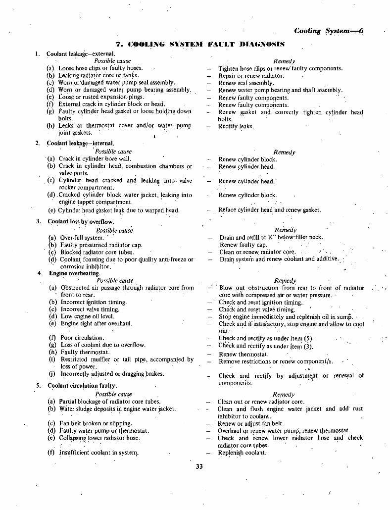
7 t OOLlNtS STIl 1 AULT IUAtNOSIS
Cooling Y3tem
L Coolant leakage external
Possible calise
a Lpose hose clips or faulty hoses
b Leaking radiator core or tanks
e Worn or damaged water pump seal assemblyd Worn or damaged water pump bearing assemblye Loos or rusted expansion plugsI External crack in cylinder block or head
g Faulty cylinder head gasket or loose holding downbolts
h Leaks at thermostat cover and or water pump
joint gaskets
2 foolant leakage internal
Possible cause
a Crack in cylinder bore wallb Crack in cylinder head combustion chambers or
valve portsc Cylinder head cracked and leaking into valve
rocker compartmentd Crackeq cylinder block water jacket leaking into
engine tappet compartmente Cylinder head gasket leak due to warped head
3 Coolani loss by overflow
Possible cause
a Over full systemb Faulty pressurised radiator capc Blocked radiator core tubes
Coolani foaming due to poor quality anti freeze or
corrosion inhi itor4 Engine overheating
Possible cause
a Obstructed air passage through radiator core fromfrout to rear
b Incorrect ignition timingc Incorrect valve timingd Low engine oil level
e Engine tight after overhaul
I Poor circulation
g Loss of coolani due to overflowh Faulty thermostati Restricted muffler or tail pipe accompanied by
loss of power
j Incorrectly djusted or dragging brakes
5 Coolant circnlation faultyPossible cause
a Partial blockage of radiator core tubesb Water sludge deposits in engine water jacket
c Fan belt broken or slippingd Faulty water pump or tltermostate Coll psing lower radiator hose
I Insufficient coobnt in systelT
Remedy
Tighten hose clips or renew faulty components
Repair or renew r diatorRenew seal assemblyRenew water pump bearing and shaft assemblyRenew faulty componentsRenew faulty componentsRenew gasket and correctly tighten cylinder head
bolts
Rectify leaks
RemedyRenew cylinder blockRenew ylinder head
lenew cylinder head
Renew cylinder bloc
Reface cylinder head and reney gasket
RemedyDrain and refill to l below filler neck
Renew faulty capClean Of renew radiator c re
Drai systemartd reneW coolant and additive
RemedyBlow o t obstruction from rear to front of radiatorcore with compressed airor water pressureCheck and reset ignition timingCheck and res t valve timingStop engine immediately and replenish oil in sumpCheck and if satisfactory stop erigineandallow to cool
outCheck and rectify as under item 5
Check and rectify as under ite 3
Renew thermostatRemove restrictions or renew compone t s
Check and rectify by adjustIlent or renewal of
components
RemedyClean out or renew radtator core
Clean and flusl engine water jacket and add rust
inhibitor to cool ntRenew or adjust fan bellOverhaul Qr ren wwater pump renew tpe mostat
Check and renew lower nidiator hose and checkradiator core tllbesRepleni r coolall
33

CARBURETTOR
Make and model
1000
1200
Primary throttle barrel diameter
1000 1200
Secondary throttle barrel diameter10001200
Primary venturi diameter1000 1200
Secondary venturi diameter10001200
Primary main jet Metric10001200
Secondary main jet1000
1200
Primary slow jet10001200
Secondary slow jet1200
Primary main air bleed1000 1200
Secondary main air bleed1000
1200
Primary slow air bleed10001200
Secondary slow air bleed1200
Power jet1000 1200
Primary main jet with altitude
compensation jetting 1000 120098 96
92
90
86
Secondary main jet with altitude
compensation jetting 1000140 135
135
FUEL SYSTEMSPECIFIC TIOS
130
Hitachi DCG286
Dual barrelHitachi DCG306
Dual barrel
26mm
28mm30mm
20mm
24mm26mm
100ths mm
95
98
140135
40
43
50
80
120
80
210220
100
60
1000 m
3300 ft2000 m
6600 ft3000 m
10000 ft4000 m
13300 ft
1000 m
3300 ft2000 m
6600 ft
34
125
Secondary main jet with altitude
compensation jetting 1200135 130
130
125
120
Float level1000
1200
tFlo t seat clearance1000 1200
3000 m
10000 ft4000 m
13300 ft
1000 m
3300 ft2000 m
6600 ft
3000 m
10000 ft4oo0m
13300 ft
10 5 mm
0413 in
I2 0mm0472 in
13 1 7 nun
0 051 0 066 in
Distance between carburettor top cover gasket surfaceand upper edge of float with float in the raised positiont Distance between float seat and needle valve stem withfloat in the lowered position
FUEL PUMP
Type
Delivery pressure1000
I ZOO
Delivery rate
1000 1 ZOO
AIR CLEANER
Type
FUEL TANK
CapacitySedan
Wagon and coupe
Mechanical
diaphragm
0 16 kg cm22Z8 psi
0 18 kg cm2Z 56 psi
450 cc per min0 7 Imp pI per mini0 8 US pt per min
Paper element
40 litre8 81 Imp gal10 57 US gal
38 litre837 Imp gall0Q4 US gal

1 Ct RBIJRETTOR
Fuel System 2
The Hitachi DCG286 and DCG306 carbureltors are
filted to the Datsun 1000 and 1200 engines respectivelyandare almost identical in constructionThe major difference between the two carburettors is
the power valve mechanism which was introduced to the1200 version to improve high speed driving
As both carburettors are quite similar overhaul
procedure etc as outlined in the carhurettor section will be
applicable to both models unless otherwise statedThe carburettor is of the twin barrel type with each
barrel incorporating a multiple venturi systemThe barrels provide a primary and secondary system
and each barrel shares a common air horn and separatemain nozzle and throttle valve
The primary system provides suitable mixtures for low
speed moderate speed and acceleration It also providesadequate mixtures for starting when the choke plate is
closedThe secondary bore provides mixtures for high speed
and also for full throttle openings at low speedA high speed valve which is incorporated in the
secondary system opens against a counterweighted lever to
enable the secondary system to maintain full mixture for
high power operation
TO REMOVE AND INSTAL
I Raise the engine bonnet and fit fender covers to
both front fenders2 Remove the air cleaner assembly3 Disconnect the fuel feed pipe4 Disconnect the distributor vacuum advance pipe5 Disconnect the choke control cable
6 Detach the tluottle cable from the carburettorthrottle lever
PRIMARY THROTTLE VALVE
T
dSPRING
lirTHROTTLE SCREW
E SCREW
HIGH SPEED VALVE
Carnurettor Flange and Main Body with Main Jets Throttle
and Idle Screws Removed Typical of Both Models
7 Remove the four nuts and washer ecuring the
carburettor to the inlet manifold and withdraw the
carburettor and gasket from the engine Discard the gasketInstallation is a reversal of the removal procedure with
attention given to the fullowingUse a new gasket between the carburettor and irilet
manifold If necessary scrape the gasket surfaces clean
making sure that no foreign matter is dropped into the inlet
manifold orifice
NOTE It is good practice to cover the inlet manifold with
rag when the carburetfor is removed for overhaul Extensive
engine damage mav result if objects are accidentallydropped into the induction Orifice
Ensure that the choke valve is fully open when thechoke control knob is in the full off position at the dash
paneLCheck the carburettor for fuel and vacuum leaks and
adjust the idling speed to the specified rpm after warm up
TO SERVICE
When overhauling the carburettor several items of
importance should be observed to ensure a thorough jobi All parts should be carefully cleaned in a suitable
solvent and then inspected for damage or wear
2 Use air pressure 9nly to clear the various oritlcesand channels
3 Replace faulty parts with new ones When checkingparts removed from the carburettor it is at times v rydifficult to be sure whether they are satisfactory for furtherservice
It is therefore recommended that in such cases new
parts be installed4 Always use a new gasket kit when overhauling the
carburettor5 It is most important that the correct fitting
35

fCHOKE VALVE
3 Fuel Sy tem
CHOKE LEVER
PUMP ACnJATING LEVER
HIGH SPEED VALVE LEYEA
Rear View of 1200 Series Carburettor Also Typical of 1000 Series
I Remove the carburetlor from the engine as
previously described
2 Disengage and remove the primary throttle return
spring3 Unscrew the retaining screw and detach the
accelerator pump actuating lever from the top cover On
1200 models remove the actuating lever return spring with
the lever4 Take out the five screws and washers and detach
screwdrivers and spanners be used when seTvicing the
carburettQf
TO DISMANTLE
FLANGE
Right Hand Side View of 1000 Series
Carburettor Typical of 1200 Series
36

the carburettor top cover assembly Disconnect the chokelink during this operation
5 Remove the three retaining screws and separate the
carburettor flange from the main body6 The carburettor has now been dismantled into its
three major components namely main body flange and topcover
TO CLEAN PARTS
1 Clean all carburettor components in petrol or
cleaning solvent and place in a suitable container
2 If compressed air is available blow each
component clean when assembling
NOTE Du not clean jets with wire drills or othermechanical means as orifices may become enlarged causingtoo rich a mixturefor proper perfomzance
3 Clean away any carbon deposits that may have
accumulated around the throttle valves
4 Discard all used gaskets and packings5 Before assembling check all fuel passages by
blowing through with compressed air
TO SERVICE MAIN BODY
1 Remove the primary and secondary main air
bleeds
2 Remove the primary and secondary emulsion
tubes3 Remove the primary slow jet4 On 1200 models only remove the secondary slow
jet5 Unscrew the two plugs to gain access to the main
jets and then remove the primary and secondary main jets6 On 1200 models remove the power valve
7 Withdraw the accelerator pump plunger invert thecarburettor body and remove the plunger spring and check
ball8 With the carburettor body still inverted allow the
accelerator pump outlet weight to become dislodged fromits bore
9 Using a small file remove the peening from the
ends of the high speed valve retaining screws and mark thevalve in relation to the carburettor body to facilitatecorrect assembly
10 With a suitable screwdriver remove the two highspeed valve retaining screws and withdraw the high speedvalve
11 Remove the high speed valve shaft from the body
NOTE Onlv remove the high speed valve and shaft fromthe carburettor bodv if it is unserviceable
12 Now that the carburettor main body is
dismantled check all components for serviceability and
make replacements as found necessary
Fuel System4
l sLOWJET
Slow Jets and Main Air Bleeds Dismantled from
Carburettor Main Body 1000 Series
13 Inspect the body for cracks and all gasket surfacesfor nicks or burrs
14 Check the power valve for smooth operation and
proper seating If necessary blow against the power valve to
ensure that it does not leak15 Check the accelerator pump plunger for wear and
for smooth operation in the plunger bore Check the springfor rust or weakness
16 Check the high speed valve shaft for excessive
play in the body and also for bend
17 Reassembly is a reversal of the dismantlingprocedure with attention given to the following
Instal all new gaskets when reassemblingPeen the ends of the throttle and choke valve retaining
screws to ensure that they will not b comc dislodged in
service
TO SERVICE TOP COVER
The carburettor top cover assembly which houses the
choke valve and shaft normally requires very little service
Do not remove the choke valve and shaft unless it is
absolutely necessary1 Remove the primary and secondary slow air bleeds
On 1000 models the primary side only
37

5 Fuel SY6tem TOP COVER MAIN BODY
POWER VALVE
SECONOARY MAIN AIR 8 O
SECQNOARY SLOW JET
ti
PRIMARY SlOW JET
C
Oto J
SECONOARV SLOW AIR OLEED
ItPOWER VALVE PISTON
PRIMARY SLOW AIR BLEED
Internal View of Carburettor Top Cover and Main Body Assemblies 1200 Series
2 Mark the choke valve in relation to the cover to
facilitate correct assembly3 Using a small me remove the peening from the
ends of the choke valve retaining screws
4 With a suitable screwdriver remove the two choke
valve retaining screws and withdraw the choke valve
5 Remove the choke valve shaft from the cover
6 Lay a straight edge across the gasket face of the
cover to check for warpage File the cover gasket face back
to a true condilion ifexcessive warpage is eviden t
7 Reassemble by carrying out the dismantlingprocedure in reverse with attention given to the foBowingpoints
Check the choke valve for proper operation Instal the
two new choke valve retaining screws and peen the ends of
the screws to ensure that they will not work loose and fall
into the inlet manifold
TO SERVICE FLANGE
I Screw out the idle adjusting screw and spring2 Remove the throttle adjusting Screw and spring3 Check the primary and secondary throttle valve
shafts for wear in the flange body If wear is not evident
then do not dismantle the shaft assemblies4 Mark the primary and secondary throttle valves in
conjunction with their respective bores File the peeningaway from the ends of the throttle plate retaining screws
and remove the screws
5 Withdraw both throttle valves disconnect the
primary to secondary connecting link and then remove
both throttle shafts from the flange6 If necessary unscrew the retaining nut and remove
the throttle lever etc from the end of the primary throttle
shaft Note how components a re situated before
dismantling to ensure correct assembly
7 Inspect the flange for cracks and the gasketsurfaces for nicks or burrs
S Lay a straight edge across the gasket surfaces and
check for warping9 Check the seating surface and the thread of the idle
adjusting screw for damageIO Place both primary and secondary throttle shafts
into their respective bores in the flange and check for
excessive clearance Renew the shafts or flange as found
necessary
I I Assemble the flange in the reverse order of
dismantling with attention given to the followingAdjust the primary and secondary throttle valves to
close fullyCheck both primary and secondary throttle valve and
shafts for smooth operation and peen over the ends of the
valve retaining screws
Turn the idle adjusting screw and spring in gently with
the fingers until it just seats and then back it off
appruximately 3 turns
Screw the throttle adjusting screw in two or three
turns
NOTE The abovementioned adjustments on the rhraule
and idle screw are olllv preliminarY adjustments Engineidle mixture and speed must be adjusted correct v with the
engine at operating temperature See adjustment section forprocedure
TO ASSEMBLE
I Assemble the flange with a new gasket onto the
carburettor main body and instal and tighten the three
retaining screws
2 Assemble the top cover to the main body with a
new gasket and instal and tighten the five retaining screWS
38

Fuel Syatem6LINK
PRIMARY THROTTLE LEVER
II Throttle and Idle Screws Installed 1200 Series rburettor
Flange Typical of 1000 Serie
3 Connect up the choke link during the above
operation4 Fit the accelerator pump actuating lever and spring
where fitted to the top cover and instal and tighten the
securing screw to retain the lever During this operationconnect the primary throttle lever to accelerator pump
actuating lever link into the inner hole on t e actuatinglever
5 Attach the primary throttle lever return spring6 Actuate all throttle and choklinkage by hand to
ensure that all mechanism is operating smoothly
PLUNGER
SPRING
TO CHECK AND ADJUST FLOAT LEVEL
1 Remove the air cleaner and carburettor top cover
assembly as previously described
2 Invert the carburettor top cover and allow the floatseat to rest against the needle valve
3 Measure the distance from the upper edge of the
Pump Components Dismantled
From Carburettor MainBody Typical Both Model
a
P7FLOAT
i lG4SKET
PIN
y
Float and Needle Valve Assembly Removed
Carburettor Top Cover Typical of Both Models

7Fuel System
floal to the carburet tor top cover gasket surface Thismeasurement should be 10 5 mm 0413 in for 000models and 12 0 mm 0472 in for 1200 models
4 If adjustment is required bend the float seat tabgently with a pair of long nosed pliers until the desiredpleasurement is obtained
With the carbureltor top cover still inverted raisethe float with the fingers until the float stopper tabcontacts its stop
6 Now measure the distance between the needlevalve stem and the float seat tab
This measurement should be within the limits as set out
in the Specificatio section un4er F oat Seat Clearance7 If found n cessary bend the float stopper tab with
a pair of long nosed pliers until the Correct float seat
clearance is obtained
CHOKE INTERLOCK ADJUSTMENT
NOTE When the choke valve is in the fully closed positionthe primary throttle valve should be opened 1 22 mm
0 048 in This wili obtain a throttle valve opening angle vf14 degrees from the fully closed position
1 Remove the carburettor from the vehicle as
previously described2 Actuate the choke operating lever by hand until
the choice valye is in the fully closed position3 Using a 122 mm 0048 iiI diameter rod as a
gauge check the clearance betfeen the primary throttlevalye and the valve bore
4 If the throttle valve clearance is larger or smaller
FLOAT ti l Ei
fv
1FLOATS AT
1 31 7 mm o l o066 n
CLEA CE
N ED LE VALVE STE
Method of Checking Float Seat Clearance Float Must beRaised Against Stop to Simulate its lowered pOsltio
1 22 mm10 048 nl OIA PRIARY THROTTLE VA VE
GAUGE ROO
Method f Checking Cho e Interlock Adjustment BothModels
than the gauge rod then carefully bend the choke
connecting rod with a pair of suitable pliers until the gaugewill just slide neatly between the throttle valve and bore
PRIMARY ANp SECONDARY THROTTLEINTERLOCK ADJUSTMEIT
The secondary throttle valve should begin to openwhen the primary throttle valve is opened 48 degreesIromthe fully closed position This angle can be assessed by
40

SECONDARY THROTTLE VALVE PRIMARY THROTTLE VALVE
I5 831T1f1 0230 nl CIA GAUGE ROO
MethOd of Checking Primary and Secondary ThrottleInterlock Opening Typical of Both Models
positioning a 5 83 mm 0 230 in diameter rod between the
primary throttle valve and valve boreI Remove the carburettor from the vehicle as
previously described
2 Position a 5 83 mm 0 230 in diameter rod as
shown in the illustration between the primary throttle
valve and ihe throttle bore
FLOAT STOPPER TAB
I
Carburettor TQp C ver with Float in the Raised Position
Showing Correct Float level
Fuel SyatemB
3 Ensure that the secondary throttle valve is fullyclosed
4 Bend the connecting rod with a pair ofpliers until
it just comes into contact with the primary throttle lever
5 Check the adjustment by withdrawing the gaugerod closing both throttle valves and then gradually openthe primary throttle valve via the throttle iever until the
secondary throttle valve just commences to open In this
position the gauge rod should just slide neatly between the
primary throttle valve and the primary throttle bore
toADJUST IDLING SPEED AND MiXTURE
I Remove the vacuum access plug from the inlet
manifold2 Connect a vacuum gauge with suitable adaptors
into the inlet manifold3 Connect a tachometer to the ignition coil
4 Start anti run the erigine until it reaches riormal
operating temperature5 Adjust the throttle idling screw until an idle speed
of 600 rpm is obtained on the tachometer
6 Adjust the idling mixture screw until the higheslvacuum reading on the vacuum gauge is obtained it may be
necessary to re adjust the jdle speed during this operation7 Stop the engine and discorinect the vaculm gauge
and tachometer
NOTE An exhaust gasanalyser ifavaiiable can be used to
adjust the mLrture or to check as a comparison with the
vacuum gauge readings An uptimum mixture strengthreading is desired on the gas analvser at engine idle Turningthe idling mixture screw in a clockwise direction gives a
lealler mLrture and anti clockwise a richer mixture
105 rill U13 I MODEL
1200MDOEl
41

9 Fuel Syatem
2 1
DESCRIPTION
The fuel pump is a mechanically operated diaphragmtype actuated by a rocker arm assembly which in turn is
operated by an eeCCll tTic on the engine camshaftWhen the carhurettor floar chamber is full and the
carburettor needle valve is closed pressure in the pumpoutlet pipe will hold the pump diaphragm downwardsagainst the pressure of the diaphragm spring
At this time the rocker arm assembly will run freely on
the diaphragm stem until the pressure in the outlet pipe isrelieved
When the outlet pipe pressure is relieved the pumpdiaphragm again rises under pressure from the diaphragmspring and into operation by the rocker ann assembly
A small compression spring holds the rocker ann inconstant contact with the eccentric on the camshaft to
minimise operating noise
A seal which runs on the diaphragm stem and which isretained in the fuel pump lower body by the diaphragmspring prevents engine oil from entering the upper sectionof the pump lower body
The rubber fuel pump diaphragm is held together bytwo metal discs and is specially treated so that it is not
affected by gasoline
TO REMOVE AND INSTAL
I Raise the engirie bonnet and fit fender covers to
both front fenders2 Disconnect the fuel inlet and outlet pipes at the
fuel pump connections
OUTLETVALVE
lIP
1 Remove the two nuts and spring washers whichsecure the fuet pump to the cylinder block and withdrawthe fuel pump with spacer and gaskets
NOTL During operation 3 lousen the luts progressiFehuntil pressure nf the diaphragm and rocker aml spring isreUelled
InstallJtion is a reversal of the removal procedure withattention given to the following
Instal new gaskets to both sides of the fuel pumpspacer
PUMP OUTLET
RETAINING SCREW
Assembled View of Fuel PumpRETAINER
DIAPHRAGM MOUNTING FACE
FUEL NLET
t
INLET VALVE
Valves Mounted in Fuel Pump Upper Body
42

COVER
SCREW
GASKET UTRBOOY
AVALVES
GbASKET 4 iJj
rL
kF SCREW
Fuel System 10
@f 0SPRING
oiISPRIN
gft
DIAPHRAGMLOWER BOOY
GASROCKER ARM
SPAeER
l Exploded view of Fuel Pump Components
RETAINER AND SCREWS
Ensure that all traces of old gasket are removed beforethe new gaskets are fitted and the pump installed
A smear of jointing compound applied to both sides ofthe gasket will help sealing
TO DISMANTLE
I Remove the fuel pump from the engine as
previously described
2 Actuate the rocker arm by hand and expel residualfuel out of the pump into a suitable container
3 Remove the pump top cover retaining screws and
detach the top COef and gasket4 With the corner of a file mark the assembled
position of the upper and lower body section of the pumpto facilitate correct assembly
5 Remove the screws from the pump upper body and
separate the two pump body section
6 Mark or note the position of the inlet and outletvalves in relation to the pump upper body section
7 Remove the two screws from the valve retainer and
take out the retainer valves and gaskets Discard the
gaskets8 Press down on the diaphragm and by using a probe
working through the rocker arm aperture in the pumplower body unhook the diaphragm stem from the end of
the rocker arm
9 Withdraw the diaphragm and lift off the diaphragmspring take out the seal retainer and withdraw the
diaphragm stern oil seal from the pump lower body10 Relieve the staking on one end of the rocker arm
pivot pin and with the pump suitably supported on the
pivot pin boss tap in one end of the rocker arm pivot pinwith a pin punch to remove it from the opposite end of the
pump bodyII Withdraw the pin punch and lift out the rocker
arm and rocker armspring
TO CLEAN AND CHECK
J Wash all components thoroughly in cleaningsolvent
2 Check the pump diaphragm and stem oil seal for
perforation and or deterioration3 Check the valve assemblies and mechanical linkage
for undue wear
4 Using a suitable flat surface or surface plate check
the diaphragm surface of the two main sections of the
pump for distortion Rectify by filing if necessary5 Renew faulty components as found necessary
NOTE If a fuel pump has seen considerable service and is
dismantled for repair or inspection it is advisable tv fit a
repair kit which includes diaphragm seal valves and gasketThis wii ensure a thorough job and further trouble freeservice from the unit
Mounting Position of Disposable Type Fuel Filter
Assembly
43

II Fuel System
TO ASSEMBLE
Assembly is a reversal of the dismantling procedurewith attention given to the following
Ensure that valve assemblies are installed correctly in
their respective seats and that each valve is fitted with a
new gasketLubricate the mechanical linkage and the diaphragm
stem with engine oil when assembling
FUEL PUMP PRESSURE TEST
I Disconnect the fuel feed pipe at the carburettor2 fit a T fitting to the fuel feed pipe and from one
junction connect a pipe back to the carburettor
3 Connect a suitable pressure gauge to the remainingjunction of the T piece
4 Start and run the engine at varying speedsobserving the pressure readings on the pressure gaugeCheck the specifications in the front of the section to
comparereconutlcnded pressures with pressure readingsA fuel pump that has a delivery pressure above or
below that recommended is unserviceable and should be
removed and dismantled for inspection
WlJlG NUT eo
LOIfEFlBODY
r
NOTE Excessivelv high pressure usualv mdicati that an
incorrecr diaphragm spring has been Jitted to he pump or
hat he diaphragm is pulled lOa rightLow pressures could be caused bv worn linkage
perforated diaphragm gummed valves or a weak ur broken
diaphragm spring
FUEL PUMP CAPACITY TEST
NOTE This test should be carried out if the pump pressure
was checked and found to be within specifications
I Run the engine for a few minutes to ensure that
the carburettor float chamber is full of fue2 Stop the engine and disconnect the fuel pump
delivery pipe at the carburettor
3 Position a measuring beaker under the pipe and
start and fun the engine at 1000 rpm for one ffilnute
4 If the capacity of fuel delivered in the beaker is
below that specified see Specitkations then either a
partial blockage in the system may be evident or the pump
is unserviceable Check the condition of the fuel filter and
blowout the fuel lines before removing the pump for
inspection
View of 1000 Inlet and Exhaust Manifold Assembly Also
TypicaJ of 1200
Dismantled View of Air Cleaner Assembly Typical of Both
Models
44

Fuel Syrem 12
DESCRIPTION
1 AIR CI HANER
The air cleaner assemblies on the two models covered
in this manual are fitted with viscous paper type elementsThe elements should not be cleaned in service but
should be renewed at the recommended mileage of 40 000kilometres 24 000 miles
This mileage is only a guide for nonnal operatingconditions and should be reduced accordingly if the vehicle
is operating under extremely dusty conditions
NOTE Paper air cleaner elements should not be washed in
petrol or any other type of so vent Elements that have
been washed in so vent or that have become oil soaked
should be discarded and a new element fitted
TO REMOVE
1 Detach tire rocker cover to air cleaner ventilation
hose2 Remove the two bolts which secure the air cleaner
assembly to the inlet manifold bracket
3 On 1200 models disconnect the additional bracket
which is secured on the inlet manifold to cylinder head
retaining stud
4 Remove the air cleaner assembly from the
carburettor5 Unscrew the wing nut and remove the top cover
from the air cleaner main body and withdraw the paperelement
t
TO INSTAL
1 With a piece of clean fluffless cloth thoroughlywipe accumulated dust away from both portions of the air
cleaner assembly2 Place the paper element into he air cleaner body
and centre it on its seat3 Position the air cleaner top cover onto the main
body and instal and tighten the wing nut
4 Instal the air cleaner assembly to the carburetlor5 Fit and tighten the two inlet manifold to air
cleaner assembly bracket bolts6 On 1200 models connect the additional bracket
which is secured to the inlet manifold to cylinder head
retaining stud
7 Reconnect the rocker cover to air cleaner
ventilation hose
1 Engine will not start
4 FUEl SYSTEM FAULT DIA NOSIS
Possible cause
a Lack of fuel in bowl
b Engine floodedwith fuel when cold byexcessive use of choke or accelerator
c Engine flooded when hot as in b above
2 Engine stalls at idle speed
Possible cause
a Incorrect adjustment of idling speedand or mixture control screws
b Carburettor float bowl flooding
c Carburettor starving for fuel
d Blocked idling jet or idle air bleed
e Carburettor to manifold attachment bolts lopsef Leaking carburettor flange or intake
manifold gasketsg Faulty gasket or loose attachment screws
carburettor main body to air horn assembly
Remedy
Check fuel pump delivery sticking or
clogged needle valve
Hold accelerator flat until enginestarts and revise starting procedureHold accelerator pedal flat until engine starts
Remedv
Check and adjust control screws
Check float level and for sticking needle valveor punctured float Clean and blowout carburettor
Check fuel delivery at needle valve Clean
and blowout carburetlor Check fuel pumpClean and blowout carburettor
Check and tighten boltsCheck and renew faulty gaskets
Renew faulty gaskets and tighten securing screws
45

13 Fuel System
3 Flat spot on acceleration
Possible cause
a Blocked accelerator pump dischargejet or sticking check valve
b Faulty accelerator pump plungerc Faulty accelerator pump linkage
4 Engine misfires or cuts out at high speed
Possible cause
a Obstruction in main or power jetsb Low fuel level in float chamber or
float chamber starving for fuelc Failure of fuel pump to
deliver sufficien t fuel
d Blockage in fuel tank pipee Restriction in fuel filter
f Air leak between fuel pump and filteror between filter and tank
g Air leak between carburettor air hornand main body assemblies or main body flange
h Water in carburettor
5 Excessive fuel consumption
Possible cause
a Float level too highb Choke butterfly partially closedc Air cleaner element dirty or
requires renewald Accelerator pump requires an adjustment
or in wrong hole in pump connecting link
e Fuel pump delivery pressure too high
f Faulty fuel pump diaphragmg Leaks between fuel pump and fuel tank
or fuel pump and carburettorh Power jet vacuum plunger stuck
in release lower positioni Faulty power jetj Worn or damaged main or power jetsk Excessive use of choke or
accelerator pump
Remedr
Clean and blowout carburettor
Renew pump plunger assemblyCheck and rectify pump linkage Check that
pump connecting link is in correct positionin the pump lever
Remedv
Dismantle and blowout jetsCheck float level setting check fuel pumpfilter and supply linesOverhaul fuel pump
Remove blockage and clean pipeClean or renew filter
Rectify air leak
Check and renew gasket and tightensecuring screws
Drain and clean fuel system
Remedy
Check and re adjust float levelCheck and rectifyClean element or renew
Re adjust accelerator pump strokewith link in other hole ofleverCheck and fit correct diaphragm spring adjustfuel pressure with pump base gasketOverhaul fuel pump and renew as necessaryGleck and rectify leaks
Free plunger or renew
Check and renew faulty jetCheck and renew faulty componentsRevise driving habits
46

CLUTCHSPEIFltATIONS
1000 SERIES
Type Single dryplateHydraulic or
mechanicalSpring tushion
Operation
Type of driven plate hiIb
Driven plateOutside diameter 160 mm
630 in
3 2mm0 126 in
llOmm4330 in
2i2 cm232 860 in2
15 87 mm
0 625 in
315mm
1 240 in
1 5 2 0mm
0 0590078 in
19 05 mm
0 750 in
23 5 mm
0 925 in
144 5 mm
5 689 in15 20mm
0590
0 787 in
Facing thickness
Inside diameter
Total friction area
Master cylinder diameter
Piston stroke
Clutch throw out bearing free travel
Slave cylinder diameter
Piston stroke
Pedal height
Chitch pedal free travel
I ioo SERIES
Type Single dryplateHydraulic or
mechanicalOperation
Type ofdriven plate hub
Driven plateOutside diameter
Spring cushion
Facing thickness
180mm7 09 in
7 8mm0307 in
125mm4 92 in
264 cm
40 92 in215 87 mm
0 625 in
Inside diameter
Total friction area
Master cylinder dl meter
Clutch throw aut bearing free traveiMechanical 0 9 1 2 mm
0 0354
0 0472 in
0 7mm0 027 in
Hydraulic
Clutch pedal free travel
Mechanical 110 15 0 mm
0433
0 591 in
30mm
1181 in
139 5
143 5 rum
5492
5 65 in
141 5mm
5 57 in
Hydraulic
Pedal heightMechanical
Hydraulic
TORQUE WRENCH SEITINGS
Pressure plate to flywheel bolts 2 2 kg m
I 5 9 ft lb
1000 SERIESI DESRIPTION
The clutch driven plate and pressure plate assembly is
of the same design as that fitted to the 1200 Series with the
following exceptionsThe throw out bearing release me chanism differs in
that the release fork is mounted on a shaft which extends
through the clutch housingThe release fork is mounted on the centre of the shaft
by means of two tapered pins with the fork extendingdown to contact the throw out bearing sleeve thus engagingand disengaging the bearing
A return spring is fitted to the shaft to assist in the
return of the fork and release uf the bearing when the
clutch pedal is returned from the depressed positionOperation of the release fork on the mechanical clutch
is by means of a cable which is connected to the arm of the
release shaft at one end and to the clutch pedal at the
opposite end
Removal of the throw out bearing and release shaft
differs in that with the gearbox removed the bearing and
sleeve are removed first tap out the tapered dowels and
withdraw the shaft sufficiently to remove the return springand fork then withdraw the shaft
Throw out bearing adjustment is achieved by adjusting
47

2Clutch
the bolt connecting the cable to the release shaft arm
Measure the distance between the lower faces of the cable
support bracket and the release shaft arm The correct
measurement oetween the two faces is to read 114 mm
4 881 in
Pedal height adjustment is obtained by adjusting thepedal stop and cable
First adjust the pedal stop and measure the distancebetween ihe top of the pedal through a centre line to thefloor
Secondly to obtain correct pedal free travel adjust thecable at the cable lower end
Where a hydraulic clutCh is fitted LH drive vehiclesthe same iype dfmaster cylinder and siave cylindet as fittedto the 1200 Series is utilised
Adju tf1ent of the throw out bea ing and clutch pedaland bleeding procedute for the hydraulic system is the sameas that of ihe 1200 Series
1200 SERIES
The single dry plate clutch comprises a press ure plateand cover assembly and a driven plate assembly the
pressure plate and cover assembly incorporates a diaphragmtype spring
The assembly has eigllteen tapered levers which are
integral with the diaphragm and maintain constant pressureon its pressure plate thus holding the driven plate to theflvwheel
The driven plate has a spring cushioned hub spiined toslide on the c10tch shaft gearbox input shaft
the spigot bearing for the clutch shaft gearbox inputshaft located in he end of the engine crankshaft is a
porous bronze bushThe clutch throw out bearing is a single row ball thrust
type mounted on the bearing sleeve which slides on theclutch shaft bearing retainer
Where a hydraulically operated clutch releasemechanism is fitted the push rod on the slave cylinder is
adjusiable to provide clearance between the throw out
bearing and diaphragm fingers with the throw out bearingin the released position
Where a mechanically operated release mechanism isfitted the cable is adjustable to provide clearance betweenthe throw out bearing and the diaphragm lingers with thethrow out bearing in the released position
TO REMOVE AND INSTAL
2 I UTU UNIT
1 Raise the vehicle and remove the propeller shaftand gearbox as described in the MANUALTRANSMISSION section
2 Mark the pressure plate cover in relation to the
flywheel so that they may be assembled in their originalpositions
3 Take out the six bolts and spiing washers securingthe pressure plate assembly to the t1ywheel releasing theni
evenly and progressively and remove the dutch pressureplate and cover assembly and the clutch driven plate
JnstaHation is a revers 1 9f the removal procedure with
particular attention to the following pointsUse the special aligning tool or used gearbox input
shaft to align the centre of the driven plate hob with thespigot bearing in the rear end ofthe crankshaft
NOTJThe raised section of the driven plate hub mustfacethe pressure plate
Align the marks on the pressure plate cover and
flywheel made on dismantlingTighten the six securing bolts evenly and progressively
Diaphragm Spring Type Pressure Plate and Driven Plate Assemblies Release Bearing Side of Pressure Plate
48

Clutch3
COVER
I
L
W0
Wh
j
DIAPHRAGM SPRING
PRESSURE PLATE
to the specified torquefitting the securing bolts
If the flexible hydraulic pipe has been discoimectedfroni the slave cylinder it will be necessary to bleed thehydraulic system
FiJI the gearbox with the recommended od and ensurethat the propeller shafi fear universal joint flange and
pinion flange are connected to the marks made on
ismantling in order to maintain the original baiance of the
shaft
Diaphragm Spring Type Pressure Plate Assembly FlyWheel Side
Fit new spring washers prior to spigot bearirig in the flywheei flange Is in serviceablecondition
This beacing is a sinterect bronze bush and requires nb
luorication in service6 Check the iIuow out bearing for n ise or
roughness
NOn When cleaning the clutch parts do not immerse iheth owout bearing in the cieaning fluid This beanng is
luqricated when assemblea and requires no furtherlubrication ih service
TO CHECK AND INSPECT
q Check that the driven plate facings are not highlyglazed or gummed with burned oil
2 If the driven plate facings are worn down to therivets check the flywheel and pressure plate faces for wear
and coring3 Check the hub of the driven plate for looseness or
wear in the hub splines Check effective action of the drivenplate hob cushion springs
4 Check that the run out of the flywheel face does
not exceed 0 050 nim o ooi in
5 Check that the clutch shaft gearbox input shaft
7 If the driven plate is stilI serviceabie do not allow
any cleaning fluid oil or grease to contaminate the platefacings
8 Do not reamthinput shaft spigot bearing Applya iight coating of high melting point grease to the bore ofthe biIsh before assembling the clutch
9 Check the flywheel and pressure plate for highspots glazing and cracking
If gIaz g and high spots are in evidenre remove the
flywheel from the crankshaft Machine ihe surfa e
removing only sufficient material to restore the flywheelface Renew both the driven plate and pressure plateassembly
MASTER VUNDER
3 Remove the two attaching bolts and withdraw the
master cylinder assembly and spacer shims
4 installation is a reversal of the renioval procedureRefill the reservoir with clean hyctratilic brake fluid and
bleed the system Ensure that hydraulic fluid is not spilt on
any painted surface
TO REMOVE AND INSTAL
I Remove the split pin and clevis pin to release the
master cylinder push rod from the clutch pedal2 Disconnect the pressure pipe at the master
cylinder
49

PUSH HOORUBBER BOOT
I PISTON AND SEAL ASSV CYLlNDE R BODY
VALVE SPRING SPRING
It
TJI4ljllllll OIDtfCIRCL
RETA N R WASH R VALV SPRING R TAIN R
J
SH7 OJWASH RS
4clutch
TO DISMANTLE
I Remove the tiller cap from the reservoir and drainthe nuid from the master cylinder and reservoir
2 Pull back the robber boot and remove the circlip3 Withdraw the push rod and stop washer4 Remove the inlet valve stop bolt from the master
cylinder and withdraw the piston assembly and returnspring
5 Remove the spring from the spring retainer lift the
spring retainer from the spigot end of the piston and takeout the spring and inlet valve
Take care not to lose the inlet valve spring6 Remove the inlet valve seal from he inleLvalve and
remove the primary and secondary cup from the pistonassembly
TO CLEAN AND INSPECT
I Thoroughly clean the master cylinder componentsand the inside of the master cyIind in methylated spiritS
2 Check the inside of the bore for wear and or
pitting Ifnecessary hone the bore3 Check the piston groove and piston body for wear
and renew the piston cups4 Check the tension of the piston return spring5 Renew the rubber boot if it shows signs of
deterioration6 Check the breather hoie in the reservoir cap to
ensure that it is clear7 Remove any sediments that may have accumulated
in the bottom of the reservoir
TO ASSEMBLE
I Dip the master cylinder components in a containerof clean hydraulic fluid and instal the new primary and
secondary cup on the piston enSuring that the cups areseated correctly and that the lip is facing the spigot end ofthe piston
Place the inlet valve seal un the inlet valve with the
lip facing the piston assembly3 Place the inlet valve spring with the tapered end on
the face of the inlet valve flange and press the springretainer down over the splined end of the piston assemblyand secure
4 Place the piston return spring over the springretainer dip the piston in hydraulic fluid and instal the
spring and piston assembly Screw in the inlet valve stopbolt
5 Insert the push rod push in and instal the retainingwasher circlip and rubber boot
6 Partially fill the reservoir with clean hydraulic fluidand pUmP the push rod until fluid emits from the cylinderoutlet
7 Fit the master cylinder to the vehicle arid ensure
that the Correct number of spacer shims are fitted betweenthe master cylinder retaining flange and the fire wall toachieve correct pedal clearance
8 Connect the hydraulic pipe to the master cylindertop up the master cylinder replace the filler cap and bleedthe air from the system as described in TO BLEED in theHYDRAULIC SYSTEM Top up the master cylinder on
completion
eM
FLU D R R
A J
@ CLIP
VALVE RELEASE BOLT
Clutch Master Cylinder Exploded ViewLeft Hand DriveModels
TO REMOVE AND DISMANTLE
4 SI AVI UNDER
I Unhook and remove the clutch withdrawal leverreturn spring connected to the lever and the lug on the slavecylinder
2 Disco ect the flexible hydraulic pipe at the slavecylinder and plug the pipe to prevent loss of fluid and
ingress of dirt
3 Unscrew the two lock nuts and withdraw the pushrod from the withdrawal lever
4 Remove the two bolts attaching the slave cylinderto the clutch housing and remove the slave cylinder fromthe vehicle
5 Draw back the slave cylinder rubber boot removethe retaining clip and withdraw the piston and push rod
from the slave cylinder Remove the seal from the piston
50
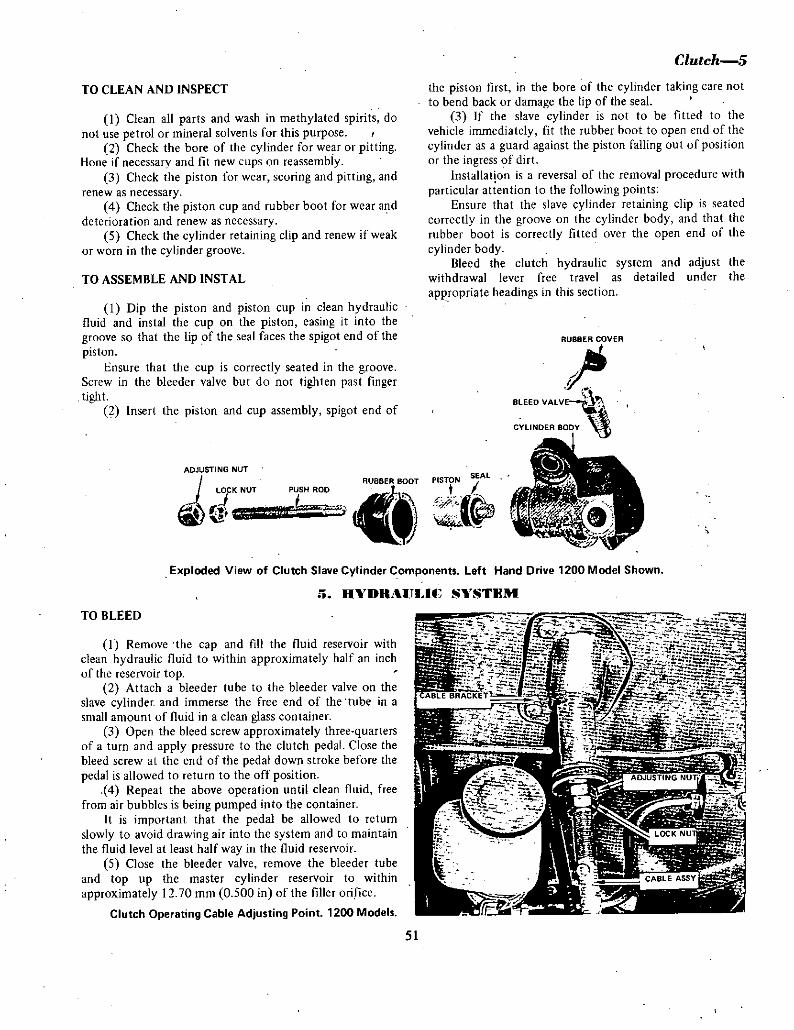
TO CLEAN AND INSPECT
1 Clean all parts and wash in methylated spirits do
not use petrol or mineral solvents for this purpose2 Check the bore of the cylinder for wear or pitting
Hone if necessary and fit new cups on reassembly3 Check the piston for wear scoring and pitting and
renew as necessary4 Check the piston cup and rubber boot for wear and
deterioration and renew as necessary5 Check the cylinder retaining clip and renew if weak
or worn in the cylinder groove
TO ASSEMBLE AND INSTAL
1 Dip the piston and piston cup in clean hydraulicfluid and instal the cup on the piston easing it into the
groove so that the lip of the seal faces the spigot end of the
pistonEnsure that the cup is correctly seated in the groove
Screw in the bleeder valve but do not tighten past fingertight
2 Insert the piston and cup assembly spigot end of
ADJUSTING NUT
LOCK NUT
fJJ iu
PUSH ROD iIiDT
rr
Clutch5
the piston tIrst in the bore of the cylinder taking care not
to bend back or damage the lip of the seal3 If the slave cylinder is not to be fitted to the
vehicle immediately fit the rubber boot to open end of the
cylinder as a guard against the piston falling out of positionor the ingress of dirt
Installation is a reversal of the removal procedure with
particular attention to the following pointsEnsure that the slave cylinder retaining clip is seated
correctly in the groove on the cylinder body and that the
rubber boot is correctly fitted over the open end of the
cylinder bodyBleed the clutch hydraulic system and adjust the
withdrawal lever free travel as detailed under the
appropriate headings in this section
RUBBER COVER
toBLEED VA LVE
CYLINDER BODY
PISTONSEA L
I Iif tAo
Exploded View of Clutch Slave Cylinder Components Left Hand Drive 1200 Model Shown
TO BLEED
HVDRAIJIU SVSTIlM
I Remove the cap and fill the fluid reservoir with
clean hydraulic fluid to within approximately half an inch
of the reservoir top2 Attach a bleeder tube to the bleeder valve on the
slave cylinder and immerse the free end of the tube in a
small amount of fluid in a clean glass container
3 Open the bleed screw approximately three quartersof a turn and apply pressure to the clutch pedal Close the
bleed screw at the end of the pedal down stroke before the
pedal is allowed to return to the offposition4 Repeat the above operation until clean fluid free
from air bubbles is being pumped into the container
It is important that the pedal be allowed to return
slowly to avoid drawing air into the system and to maintain
the fluid level at leasthalf way in the fluid reservoir
5 Close the bleeder valve remove the bleeder tube
and top up the master cylinder reservoir to within
approximately 12 70 mm 0 500 in of the filler orifice
Clutch Operating Cable Adjusting Point 1200 Models
51

6Clutch
6 1 tJTCH THROW OUT BEARING
MECHANICAllY OPERATED CLUTCHTO RENEW 1000 SERIES
1 Remove the gearbox and clutch bell housingassembly as described in the TRANSMISSION SECTION ofthis manual
2 Unhook and remove the bearing return spring fromthe release shaft fork
3 Slide the throw out bearing and hub assemblyforward along the gearbox input shaft bearing retainersleeve and withdraw from the bellhousing
4 Tap out the two tapered pins securing the releaseshaft fork to the shaft and withdraw the shaft sufficientlyto remove the fork and return spring from the shaft andwithdraw the shaft from the bellhousing
5 Inspect the release shaft and fork for wear anddistortion
6 Check the release shaft bushes in the beUhousingfor wear
7 Using a suitable puller or press remove thethrowout bearing from the bearing hub and check the
bearing hub for wear
Replace all worn or damaged components where
necessary
jjNS EL
iLEVE
l E RE RN SP G
AFT
rBEAAING RETAINER SPRING
BEARING AHDstEEVE
fJIJExploded View of Clutch Release Components 1000 Models
8 Instal the new throw out bearing on the bearinghub 0 that the thrust face of the bearing is facing awayfrom the end of the hub
NUTE Applv pressure to the inner race vf the bearingwhen instaingon the bearing hub
9 Insert the bearing release shaft sufficiently into the
housing to instal the return spring and release shaft forkIO Posh the release shaft fully home and check the
movement tIld alignment in the bellhousingII Centre the fork on the shaf and tap in the two
tapered pins and check that they are secure
12 Lightly lubricate the input shaft and sleeve with
high melting poin t grease13 Instal the bearing and hub assembly on the input
shaft bearing retaining sleeve and position the fork on the
bearing hub
14 Instal the bearing return spring on the bearing huband locate the end of the spring on the fork
IS Check the operation of the clutch release
mechanism and instal the gearbox and bellhousing assemblyin the vehicle as described in the TRANSMISSION sectionof this manual
16 Adjust the clutch release shaft free travel to
specifications as detailed in under ADJUSTMENTS in thissection
MECHANICALLY OPERATED CLUTCHTO RENEW 1200 SERIES
I Remove the gearbox and clutch bellhousingassembly as described in the TRANSMISSION section ofthis manual
2 Remove the rubber dust excluder from the end ofthe withdrawal lever and the aperture in the bellhousing
3 Separate the withdrawal lever return spring fromthe lever and throw out bearing and witlldraw thethrow out bearing and bearing hub out over the input shaftbearing retaining sleeve
4 Disengage the withdrawal lever from the lever pivotpin and withdraw the lever from the bellhousing
5 Using a suitable puller or press remove thethrow out bearing from the bearing hub
6 Clean the components excluding the bearing in a
suitable solvent and allow to dry7 Inspect the bearing hub withdrawal lever pivot
pin return spring and dust excluder for wear damage and
fatique Renew worn or damaged components wherenecessary
8 Instal the new throw out bearing on the bearinghub so that the thrust face of the bearing is facing awayfrom the lever end of the hub
NOTE When installing the bearing ofl the bearing hub the
pressure must be applied to the inner race of the bearing
52

Unless this procedure is adhered to the bearing will be
damaged
9 Position the end of the withdrawal lever in the
aperture of the bellhousing and locate the opposite end ofthe lever on the lever pivot pin
10 Lubricate the gearbox input shaft bearing retainer
sleeve sparingly with a high melting point grease and instal
the throw out bearing and bearing hub on the sleeve
11 Locate the ends of the withdrawal lever return
spring in the holes in the lever and the throw out bearinghub
NOTE Ensure that the spring ends are correctly lucated
prior to installation of the gearbox and belhousingassembly
12 Instal the rubber dust excluder over the end ofthe withdrawal lever and ensure that it is correctly seated inthe clutch bellhousing aperture
13 Instal the gearbox and bellhousing assembly in
the vehicle as described in the TRANSMISSION section ofthis manual
14 Adjust the clutch withdrawal lever free travel to
specifications as detailed under ADJUSTMENTS in thissection
HYDRAULIC CLUTCH
TO RENEW 1200 SERIES
I Remove the gearbox and clutch bellhousingassembly as described in the TRANSMISSION section ofthis manual
2 Remove the rubber dust excluder from the end ofthe withdrawal lever and the aperture in the bellhousing
3 Remove the return spring from the throw out
bearing hub and withdraw the bearing and hub assembly4 Remove the withdrawal lever from the lever pivot
pin and withdraw the lever from the clutch bellhousing5 Using a suitable puller or press remove the
throw out bearing from the bearing hub6 Clean the components excluding the bearing in a
suitable solvent and allow to dry7 Inspect the bearing hub withdrawal lever pivot
pin bearing return spring and dust excluder fof wear
damage and fatigue Renew worn parts and damagedcomponents where necessary
8 Instal the new throw out bearing on the bearinghub so that the thrust face of the bearing is facing awayfrom the lever end of the hub
Clutch 7
Non When installing the bearing on the bearing hub the
pressure must be applied to the inner section of the beanngUnless this procedure is adhered tu the bearing will be
damaged
9 Position the end of the withdrawal lever in the
bellhousing aperture and locate the lever on the lever pivotpin
10 Lobricate the gearbox input shaft bearing retainer
sleeve sparingly with high melting point grease and instal
the throw out bearing and hub assembly on the gearboxinput shaft sleeve
11 Position the throw out bearing return spring on
the throw out bearing ensuring that it is correctly seated
on the bearing and in the bellhousing12 Instal the rubber dust excluder over the end of
the withdrawal lever and ensure that it is correctly seated in
the clutch bellhousing aperture13 Instal the gearbox and bellhousing assembly in
the vehicle as described in the TRANSMISSION section ofthis manual
14 Adjust the clutch withdrawal lever free travel to
specifications as detailed under ADJUSTMENTS in this
section
OBEARING SLEEVE I
LEVER
RETAINER SPRING
PIVOT BOLT
Clutch Withdrawal Lever and Bearing Typical Left Hand
Drive Models
53

8Clutch
HYDRAULIC CLUTCH
7 U TB PIlD4L
To Remove and Instal
I Disconnect and femove the clutch pedal return
spring2 Withdraw the split pin and washer take out the
clevis pin and disconnect the clutch pedal from the master
cylinder push rod3 Unscrew the self locking nut remove the flat
washer waved washer and withdraw the clutch pedal pivotbolt and lift oot the clutch pedal Remove the two nylonflanged bushes from the metalspacer
4 Check the pedal bushes and pivot bolt for wear
5 Check the clevis and cleviS pin for wear6 Replace all components where necessary7 lightly apply high melting point grease to the
pedal bush and pivot bolt and instal the nylon bushes in themetal spacer
8 Place the clutch pedal in position and insert the
ADJUSTING B
LOCK
NUT
SCREWED CABLE END
I
jJINNER CABLE
it
CABLE BRACKET
SPRING
r
Exploded View of Clutch and Brake Pedal Fulcrum Bushes
Pin and Clutch Cable 1000 Models
piVOI bolt fit the waved washer and flat washer and secure
with the self locking nut
9 Align the holes in the clevis with the hole in the
clutch pedal instal the clevis pin and secure with the flatwasher and new split pin
10 Instal the clutch pedal return spring and checkthe operation of the pedal
PEDAL AND CONTROL CABLE
To Remove and Instal 1000 Series
Removal and installation induding components of theclutch pedal on the 1000 Series is the same as for the
hydraulic system with the exception that the clutch control
clevis coupling is connected to the top of the clutch pedaLI To remove the control cable from the clutch pedal
remove the split pin and flat washer withdraw the clevis
pin from the clevis thus disconnecting the clutch controlcable from the slot at the top of the clutch pedal
2 Withdraw the clevis and the outer cable from the
firewall at the upper end3 Working at the clutch release shaft end disconnect
the lower end of the control cable from the release shaft4 Loosen the two lock nuts connecting the inner and
outer cable to the cable support bracket attached to the
engine and separate the cables from the support bracket5 Withdraw the control cable from the vehicle and
check the outer cable for damage or fatigue6 Check lock nuts for thread damage and the rubber
insulators for fatigue7 Replace all worn or damaged components where
necessaryInstallation is the reverse procedure to that ofremoval
with attention to the followingLobricate the cable with molybdenum disulphide
grease
Adjust the pedal height and release shaft free travel to
specifications as detailed under ADJUSTMENTS in thissection
Tn Remove and Instal 1200 Series
Removal and installation including cnmponents of the
dotch pedal on the 1200 series is the same as for the
hydraulic system with the exception that the clutch control
clevis coupling is cnnnected to the top of the clutch pedalI To remove the control cable from the clutch pedal
unhook the clutch cable from the slot at the top of the
clutch pedal2 Remove the three screws attaching the control
cable flange to the fire wall3 Working at the lower end of the control cable
disconnect the cable from the withdrawal lever
54

4 Release the lock nuts at the upper end of the outercable and withdraw the cable assembly
5 Inspect the inner and ooter cable for fraying and
external damage6 Replace worn or damaged components where
necessary
Clutch 9
Installation is the reverse procedure to that of removalwith attention to the following
Instal the control cable with the grease nippleuppeqnost to facilitate lubrication and lubricate the cable
Adjust the clutch release lever free travel and pedalheight to specifications as detailed in this section
HYDRAULIC CLUTCH
8 AD JlJSTMENTS
To Adjust Pedal Height
Pedal height adjustment is carried out in two stages1 Check the pedal height by measuring in a straight
line with a steel rule the distance from he floor to the topof the pedal pad The correct measurement shoold be 143 5
mm 5 65 inIf adjustment is necessary back off the pedal stop
loosen the two bolts attaching the master cylinder to the
fire wall and add or remove adjusting shims as required to
obtain the correct pedal heightEnsure that the upper and lower adjusting shims are of
equal thickness and that the two bolts attaching the master
cylinder to the fire wall have been secured on completionof this adjustment
2 Measure the distance between the floor and the topof the pedal pad and adjust the pedal stop so that the pedalpad height is 141 5 mm 5 57 in
Tighten the pedal stop lock not and recheck the
measurements
To Adjust Withdrawal Lever Free Travel
1 Raise the front of the vehicle and sopport on
stands or support the complete vehicle on a hoist2 Apply clutch pedal and allow to return to the off
position3 Check the adjustment by measuring the free travel
of the lever from the full off position and the positionwhen the thrust bearing contacts the clutch diaphragmfingers
4 If adjustment is required slacken the lock nut on
the slave cylinder push rod and turn the adjustment nut to
achieve the specified free travel of the withdrawal lever See
Specification section
5 Hold the adjusting nut and push rod and tightenthe lock nut Recheck the free travel
PEDAL AND CONTROL CABLE
To Adjust 1000 Series
Pedal height adjostment is obtained by adjusting the
pedal stop
i Check the pedal height by measuring in a straightline with a steel rule the distance from the floor to the top
Clutch Release Mechanism Cable Operated 1200 Models
of the pedal pad The correct measurement should be 144 5
mm 5728 in
Ifadjustment is necessary back offthe pedal stop lock
nut and adjust the stop to obtain the correct pedal heightTighten the lock nut and recheck the pedal pad height
2 Working at the lower end of the cable release the
lock nut on the adjusting bolt and measuring the distancebetween the lower face of the release shaft lever and the
under side of the cablc lower support bracket The correct
measorement between the two faces is 124 mm 4 881 in
with the release shaft free travel reading 1 5 2 0 mm
0 059 0078 in
Tighten the lock nut and recheck both measurements
To Adjust I200 Series
Pedal height adjustment is carried out in two stagesI Check the pedal pad height by measuring in a
straight line with a steel rule the distance from the floor to
the top of the pedal padThe correct measurement should be from 139 5 to
143 5 mm 549 5 65 in
Shoold pedal height adjustment be necessary back offthe pedal stop lock nut and adjust the pedal stop to obtain
the correct pedal height
55

1 iUtch
Secure the lock nut and recheck the pedal pad heigllt2 Release the lock nut at the upper end of the outer
cable and adjust the pedal free travel
Adju t the cable uhtil a free travel of between II 15
rum 0433 0 591 in from the original pedal height settinghas been ohtairiect
Check the bearing release lever free travel and this
reading should be 3 0 40 rum 0 1 i81 0 1575 in
Should the bearing release lever free travel not be
within this tolerance readjust the pedal free travel
Tighten the cable adjusting lock nut and recheck thefree travel
IClutch slipping
9 LUTfU FAIJI T DIAGNOSIS
Possible cause
a Clutch bleadjustfnentb Weak or broken diaphragm springc Worn driven plate facingsd Worn or scored flywheel face
2 Gutch shudder
Possible cause
a Oil or gummy driven plate facingsb Scor d pressure plate or flywheel
c Loole or damaged engine mountingd Loose or damaged driven plate hube Loose driven plate facingsf Cracked pressure plate face
3 Gutch grab
Possible cause
a Gummy driven plate facingsb Cracked pressure piate faceel Loose or broken engine mountings
4 Throw out bearing noise
Possible cause
a Dry or seized bearingb Incorrect clutch cable adjustmentc Faulty or broken diaphragm spring
5 Insufficient clutch release
Possible cause
a Excessive free travel of clutch pedalb Excessive play of release leverc Pilot bushing siickingd Clutch disc warpede Leaking master cylinder cupf Leaking shive cylinder cupg Air in hydraulic systemh Low fluid levei in reservoir
Remedy
Check and adjust to spepificationsCheck and renew assemblyCheck arid renew driven plateRenew flywheel and ring gear
Remedv
Check and renewdriven plateJeriew pressure plate and cover
assembly or flYYheel and ring gearCheck arid renew mountings as riecessaryCheck and renew driven plateRenew or check driven plateRenew pressure plate and cover assembly
Remedv
Renew driven plateRenew pressure plate and cover assemblyCheck and renew engine mountings as
necessaiy
Remedy
Checkand renew bearingCheck and readjust to specificationCheck and renew pressure plate assembly
Remedv
Adjust correctlyAdju t correctly
eplace pilot bearingReplace clutch disc
Replace cupRepl ce cupBleed systemTop up with brake fluid
56

MANUiTILNSMJSSIONSPEClFlATlQNS
I THREE SPEED TRANSMISSIONi ARBOX
The laygear operates on two ball type bearings whichlocate in tile carrier plate and ge lbox casing Laygearend float is adjusted by a washef which can be obtained in
differ nt thickness s for this purposeainshaft laygear and reverse idler are attached to the
carrieipl te whicll is interposed between the ge f case andreaf extelsi9n The m in raft operate on two ball type
GEARBOX
3 SPEED
Type 3 speed with
rem9te controlcolunID cljangeOn all forward
gears
Synchromesh
Ratios
TopInterme iate
IDwReverse
1 00 I
173 I
338
3 61 I
4 SPEED
Type 4 speed with
flogr changeqn all forwardears
Synchromesh
Ratios
TopThirSecondFir t
Reverse
100
1402 173 76
3 64
and 4 SPEEDGear end float
Ist and 2nd gears all 0 15 0 25 mm
0 0060 01 0 in
0 15 035 rum
0 006
0 014 in
01 0 0 25 mm
0 0040p1O in
0 05 0 1 mm
6 0020 006 in
3rd gear 4 speed
Reverse ear 3 speed
Reverse idler 3 speed
Baulring to gear clearanceStandar 105 140 mm
0 040 CO
0 055 in
PAQT
DESCRIffION
The three speed gearbox has synchrqme ori all
forwar gears The gears are helical cut and run in con tarytmesh with the laygear Revefse gear funs in mesh with a
everse i ler gear which i constan tly m shed with theIaygear
Minimum 0 5mm0 020 in
0 08 0 15 mm
0 0030 006 in
Gear backlash
LaygeaEnd float O O I mm
0 0 004 in0 8 13 mm
incremeQts ofO lmm
0 031 0 051in incrementsof 0 004 in
Thrust washer sizes for adjustment
Fron bearifg cov r
Adjustin shim size 0 1 0 2
0 5 mm
0 004 0 0080 020 in
Detent springLength at lo d 164111m at
7kg0 6457 in
at 154lb
PROPELER SHAFT
TypeNumber of universal jointsType 0 univ rsal j ints
Oper tubular2
Needle rollerbe ring and
trunnion
TORQUE Wl ENfSEITINGS
Main drive bearing retainer 10 I 4 kg m
7 10 ft lb1 6 2 2 kg m
12 16 f IbExtension housing
t
57

I
2 lUtmual Transmission
bearings which also locate in the I arrier plate and gearboxcasing
Front bearing end float is adjusted by shims which are
available ill different thicknesses for this purpose All
mainshaft gears run on needle roHef bearings A needle
roller bearing is also used to mount the input shaft tn themainshaft
The gear change is the remote control type mounted on
the steering column Rods transfer the gear change levermovement to operating levers located in the gearbox case
and throogh selector forks to the synchro sleeves Rodadjustment is carried out at the steering box end of therods
TO REMOVE AND INSTAL
J Jack up the front of the vehicle and support on
axle stands
2 Remove the drain plug and drain the oil from the
gearbox3 Disconnect the exhaust pipe at the manifold and
holding brackets4 Disconnect the speedometer cable at the rear
extension housing5 Mark across the edges of the rear universal joint
and axle pinion flanges to ensure reassembly in their
original positions6 Disconnect the universal joint flange from the
pinion flange and withdraw the propeller shaft from therear of the gearbox
7 Take out the spring clips and detach the gear
change rods from the operating levers and relay shaft8 Detach the relay shaft from between the gearbox
and side plate9 Disconnect the clutch cable from the clutch lever
or clutch slave cylinder where fitted from the bell
housingJ 0 Loosen off and remove the starter motor
11 Take out the bolts and remove the dust shieldfrom the lower half of the bell housing
12 Support the engine and transmission on a jack
l1
13 Remove the bolts attaching the rear gearboxmounting cross member to the chassis and extension
housing14 Unscrew and remove the bolts securing the clutch
bell housing to the rear of the engine15 Carefully draw the gearbox rearward lower it to
the floor and remove from beneath the vehicleInstallation is a reversal of the removal procedure
TO DISMANTLE
t I Disconnect the release bearing retaining springfrom the release fork and withdraw the bearing and sleeve
assembly2 Knock out the taper pins securing the release fork
to the release shaft and lever Withdraw the shaft from the
case and fork 1000 model only3 Take out the three bolts retaining the mainshaft
front bearing cover to the case and withdraw the cover 0
ring and shims
NOTE Check the number of adjusting shims fitted to
facilitate adjustment at reassembly
4 Remove the two bolts retaining the speedo driven
gear assembly to the extension housing and withdraw the
assembly5 Remove the bolts securing the extension housing
to the carrier plate and gearbox casing6 Withdraw the extension housing from the rear face
of the carrier plate It may be necessary to ease the housingoff the plate dowels this can be best accomplished byexerting upward pressure on the housing while tapping the
ends of the dowels with a punch and hammer
7 Hold the mainshaft and using a soft faced hammer
gently tap the gearbox casing to separate the carrier plateand gear assembly from the casing
NOTE Check the number ofadjusting shims at the front ofthe aygear to facilitate adjustment at reassemblv
8 Mount the carrier plate and gear assembly in the
jaws of a vice fitted with protective covers
9 Remove the circlip and thrust washer at the front
SYNCHRO ASSY
Lay Gear and Main haft Assembly
58

Manual Tra smission3
1ST REVERSE SELECTOR ROD AND FORK
REVERSE LIGHT SWITCH
of reverse idler gear shaft and also at the rear carrier plateface end of the shaft
10 Knock out the idler shaft from the rear face ofthe carrier plate and detach the idler gear and rear thrustwasher
I I Support the selector forks and knock out the
spring pin attaching each fork to each selector rod
12 Unscrew the plug retaining the detent spring andball in the end ofthe carrier plate
I
13 Tap the 1st reverse selector rod out of the carrier
plate allowing the rod to move through the fork
14 Repeat the operation for the 2nd top selector rodand remove the interlock plunger located in the carrier
plate between the selector rod holes
NOTE A n additional detent ball and springare located in a
blank ended hole in the carrierplate and should lie removedwhen practicable
15 Using a soft faced hammer tap the rear end of themainshaft to dislodge the bearing from the carrier plate It
may be also necessary to tap the Jaygear rear bearing to
enable the laygear and mainshaft assembly to be withdrawntogether from the carrier plate
16 Pull the input shaft from the end of the mainshaftassembly remove the needle roller bearing if attached tothe mainshaft spigot
2ND TOP SELECTOR ROO AND FORK
INPUT SHAFT
L1
View of Gearbox with Gear CaseRemoved to Show Internal Assembly
1ST REVERSE SELECTOR FORK
1ST REVERSE SELECTOR ROD
10 THF
i 9bQOWASHE SHIMS
BAULK RING
Exploded View of Input Shaft Components
59

ltjr IoJoo ir1 t oJ
REVE EGEAR BAUL NG TtGEA BL NG SYNC O ASSEMBLY
t LOCATINGBALL
4111anual Trammission
CIRCLlP BEARING
MAINSHAFTI
Exploded View of M inshaft Component
17 Remove the thrust washer and ball bearing from 6 Check the baulk rings on their corresponding gearthe end of the mainshaft followed by the baulk ring cones for wear see specificationssynchro hub assembly second baulk ring and second gear
7 Check the selector forksfowear the selector
complete with needle roller bearing detent balls for wear and the detent springs for breakage or
18 Remove the circlip and washer retaining the loss of tension see specificationsmainshaft rear bearing and remove the bearing 8 Renew all worn or damaged components as
119 Withdraw the thrust washer reverse gear with necessary
needle roller bearing and mainshaft bush20 Remove the synchro hub assembly followed by
the bau1k ring and low gear with needle roller bearing
NOTE Some mainshaft assemblies may have the gearsmounted on a narrow section roller bearing with theaddition of a bearing spacer Note the spacer position when
dismantling to facilitate reassembly
21 Before dismantling the extension housing markthe position of the levers in relation to the housing
22 Remove the nut and washer and kIiock out the
cotter pin retaining the low reverse selector lever to thecross shaft
23 Withdraw the cross shaft from the housing and
selector lever24 Repeat the operation to remove the second top
cross shaft and selector lever25 If replacement of the oil seal and or the main
shaft bush is necessary knock out the components fromthe rear of the extension housing
26 If replacement of the input shaft bearing is
necessary remove the circlip and washer and press or draw
the bearing from the shaft
TO CLEAN AND INSPECf
I Clean all components in cleaning solvent and blow
dry with compressed air2 Check ball bearings for roughness or excessive side
play Do not rotate the bearings at high speed with
compressed air particularly when the bearings are dry or
damage will result3 Check needle roller bearings for wear and or
pitting4 Examine the teeth on all gears for wear and or
pitting also burring on the teeth ends5 Check the synchronising teeth on the gear for wear
or chipping
TO ASSEMBLE
I Instal the low gear and needle roller bearing on the
main shaft with the gear cone facing to the rearof the shaft
NOTE Instal the bearing spacer if originally fitted and oil
components during assembly
2 Position the baulk ring on the gear cone
3 If the synchro hub has been dismantled instal the
synchro plates in the hub slots and slide the sleeve over thehub splines Fit the synchro springs under the synchro platelugs at each side to tension the plates
NOTE The svnchro springs must be installed so that when
viewed from one side they travel in opposite directions
4 Instal the synchro hub assembly on the mainshaft
engaging the ends of the synchro plates in the notches ofthe baulk ring and the hub splines on the mainshaft splines
5 Lubricate and instal the needle roller bearing and
mainshaft bush for reverse gear6 Position the reverne gear on the mainshaft with the
gear cone facing the synchro hub assembly
NOTE Instal the bearing spacer if originally fitted
7 Instal the thrust washer and press the rear bearingonto the mainshaft
8 Position the tension washer on the mainshaft so
that the concave face of the washer faces the bearing9 Instal the circlip and check that it is correctly
seated in the groove of the mainshaft
10 Check the end float between the reverse gear and
thrust washer and the first gear and mainshaft flange See
specifications for end float clearance
NOTE If end float exceeds the limit renew the thrust
washer
60

11 Instal the second gear needle roller bearing on thefront of the mainshaft
12 Instal bearing spacer if originally fitted
13 Position the second gear on the needle roller
bearing with the gear cone facing forward
14 If dismantled assemble the synchro hub as
previously described
15 Position the synchro hub assembly on themainshaft so that the synchro plate ends engage the baulk
ring notches and the hub splines engage the mainshaftsplines
16 Instal the ball bearing in the mainshaft recess
grease bnth faces of the thrust washer and instal so that theoil groove side of the washer abuts the synchro hub Locatethe notch in the thrust washer over the ball bearing
17 Position the baulk ring so that the synchro plateends engage the baulk ring notches
18 Lubricate and instal the needle roller bearing on
the mainshaft spigot19 If the input shaft has been dismantled press on
the bearing and secure with the washer and circlip20 Position the input shaft on the mainshaft needle
roller bearing and engage the gear cone in the baulk ringMainshaft assembly is now completed ready for installation
NOTE Before the laygear assembly can be installed to the
mainshaft assembly it will be necessary to check the
laygear end float in the gear case This is essential
particularly if any partsof the assembly have been renewed
21 Ensure that the circlip is correctly located in thebearing aperture at the front of the gear case
22 Instal the laygear in the case so that the bearingabuts the circ1ip
SYNCHRC ASS
THRUST WASHERND GEAR
Thrust Washer Must be Fitted with Dumpled Face Forward
Manrtal Tranamiaaion5
ST REVERSE CROSS SHAFT
LEVER
IIr
COTTER P1N lo
LEVER
Q RINGSEALS
THRUST
WASHERtiIiIr E ClIP
NorrOP CROSS SHAFT
Exploded View of Selector Cross Shaft Components
23 Using special tool No ST4367 position the tool
across the faces of the pen end of the gear case with the
laygear rear bearing located immediately below the cutawayin the tool
24 Insert the thrust washer originally removed on
dismantling between the top face of the bearing and thelower edge of the gauge cutaway
25 Using feeler gauges check the remaining gapbetween the washer and gauge Measure the thickness of thewasher and add the thickness of the feeler gauges usedDeduct from the total measurement 0 03 mm 0 001 in forend float The balance remaining is the thickness of thewasher necessary for correct adjustment See specificationsfor washer thicknesses and end float tolerance
26 Alternatively if the special toolJis not availablethe Plastigage method can be used as follows
27 Cut three pieces of Plastigage or soft lead wire tofit an the bearing aperture flange in the carrier plate spacethem equidistant around the flange
NOTE To hold the three pieces ofPlastigage or lead wirein position it may be necessary to use a smear ofgrease
28 With the laygear installed as described in
operations 21 and 22 fit the carrier plate into positionover the laygear rear bearing and onto the gear case
29 Instal the carrier plate retaining bolts and tightenthem evenly and diagonally to a torque of 12 16 ft lb
30 Remove the carrier plate and carefully detach thepieces of Plastigage or lead wire from the flange
NOTE Provided thePlastigage or lead wire wasof adequatethickness it should now be in a flattened condition
31 Using a micrometer check the thickness of eachpiece of compressed Plastigage or soft lead wire and arriveat a mean figure Deduct from this figure the necessaryend float operation 25 and the balance represents the
thickness of the washer required32 Remove the laygear assembly from the gear case
33 Mount the carrier plate in the jaws of a vice fittedwith protective covers
61

6Manual Transmission
GEAR SHAFT
I
t
THRUST WASHER
NOTE Ensure that both bearings enter the apertures
squarely and do not allow the gear teeth to come out ofmesh
37 Instal the selector forks to the synchro sleeves
38 Instal a detent spring and ball to the blank endhole in the carrier plate and using a piece of rod depressthe ball and spring and hold in this position
39 Insert the second top selector rod through the
PLUoIIR
DETENT 8ALL
INTERLOCK PLUNGER
@oETENTBALL
I SPRING
CARRIER PLATE
L
l j
Order in which Selector Road Detent Components are
Fi to the Carrier Plate
Exploded View of Reverse Idler Components
selector fork and into the carrier plate with the threedetents on the selector rod facing the detent ball
40 When the selector rod engages over the depresseddetent ball remove the holding rod and push in the selector
rod until the ball engages in the centre detent on the shaftInstal the stop circlip at the rear end of the selector rod
41 Insert the interlock plunger into the hole locatedat right angles to and between the selector rod holes
42 Instal the first reverse selector rod with the singledetent on the rod facing the interlock plunger
43 Drop the remaining detent ball and spring into
the hole on the edge of the carrier plate and screw in the
plug until it is flush with the plate edge
NOTE The position of the detent plug regulates the
amount of tension on the detent ball and spring Normalvit is correct when set as described in operation 43
44 Firmly support the selector rods and forks alignthe hole in each rod and fork and tap in the retaining springpins
45 With the gears in neutral position instal thereverse idler gear with front and rear thrust washers
46 Tap the idler shaft into position and secure with
circlips at the front and rear of the shaft47 Check the end float on the reverse idler gear and
renew the thrust washers if the clearance exceeds
slecifications48 Instal the selected laygear end float adjusting
washer to abut the circlip in the front bearing apertureSmear with a little grease to hold in position
49 Instal the carrier plate assembly into the gear case
so that the front bearings of the mainshaft and laygearas emblies enter the bearing apertures squarely
50 Check that the dowel holes and dowels are
aligned in the carrier plate and gear case Use a soft facedhammer and gently tap the carrier plate down into position
51 If the extension housing components have beendismantled assemble as follows
62
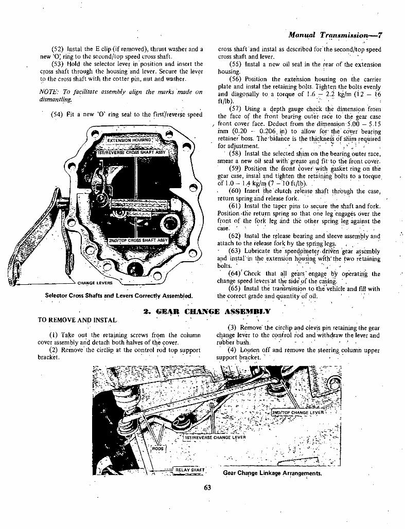
52 Instal the E clip if removed thrust washer and a
new 0 ring to the second top speed cross shaft53 Hold the selector lever in position and insert the
cross shaft through the housing and lever Secure the levert the cross shaft with the cotter pin nut and washer
NOTE To facilitate assemblv align the marks made on
dismantling
54 Fit a new 0 ring seal to the fiItreverse speed
Selector Cross Shafts and levers Correc y Assemb ed
Manual Tran mi ion 7
cross shaft and instal as described for the second top speedcross shaft and lever
55 Instal a new oil seal in the rear of the extension
housing56 Position the extension housing on the carrier
plate and instal the retaining bolts Tighten the bolts evenlyand diagonally to a torque of 1 6 22 kg m i 2 i6ft lb
57 Using a epth gauge check the dimension fromthe face of the front bearing outer race to th gear case
front cover face Deduct from the dimension 5 00 5 15inm 0 20 0 206 in to allow f r th cover bearingretainer boss The balance is the thicklles s of sni requir dfor adjustment
58 Instal the selected shim on the bearing outer race
smear a new oil seal with grease anq fit to the front cover59 Position the front over with gasket ring on the
gear case instal nd tighten the ret inlng bo1ts to a torqueof 10 I 4 kg m 7 10 ft l
60 Insert the clutch release shaft through the case
return spring and release fork
61 Instal the taper pins to secure the shaft and forkPosition tne return spring so that one leg engages over the
front of the fork leg and the other spring leg against thecase
62 Instal the release bearing and sleeve assem ly and
attach to the release fork by the spring legs63 Lubricate the speedpinete driven gear assembly
apd in tar in t e extension h8using with tpe wo r tainingbolts
64 Check that a 1 gears engage by operatiPg the
change speed levers at the side pf the casing65 Instal the tran mission to the vehicle and fin with
the correct grade and quantity of oil
TO REMOVE AND INSTAL
2 GE DANGE ASSE1UBLY
1 Take out the retaining screws frm the columncover assembly and detach both halves of tle cover
2 Remove the circlip at the control rod top supportbracket
R LAY SHAfT
3 Remove the circlip and clevis pin retaining the gear
clange lever to the control rod and withraw the lever and
rubber bush4 Lapsen off and remove the steeri g column upper
support r cket
r
Gear Charge Linkage rfange ents
63

8 Manu l Tran lfliuion
CIRCLlPf
WASHER
rlBUSH
INSERTj8Ji0 PIN f
J I r
SPRI G
Lof GEAR C ANGE LEVER
ecLlP
CONTROL ROD
1ST AND REVERSE LEVERRETAINER
l CLAMP BRACKET
3Jfl 1
iifYSADDLEBOLT
I B ARING BOSS AND SUPPORT
it 2ND AND TOP LEVER
PIN
Y
tBOLT Q RpAINER
Iumn Contro Gear al1ge Comp9nents
5 Remove the screws attaching the rubber dust sealto the floor boards and work the seal up the column
6 Working at the steering box disconnect both gearchange rods from the control rod levers
7 Remove the two set bolts from the bracket
retaining the lever assembly to the steering columnMove the control rod assembly down the column
to facilitate rerpoval of the spring swivel pin and bush fromthe upper end of the control rod
9 Ease the control assembly down and out from thevehicle working the rod through the rubber dust seal
Jnstallation is a reversal of the remava procedure
TO DISMANTLE AM ASSEMBLE
I Remove the set bolt retaining the s dd1e to theco trol rod lever bearing boss nd remove the saddle
2 From the end of the control rod remove the
groove retainer op rating lever and be ring boss3 Extract the pin from the hole in tIie control rod
and remoVe the remaining operating lever llnd groovedretainer
4 Clean all components and examine tlje bearingbushes for wear Re eV al1Y components which are worn or
damaged Lubricate components during assemblyAssembly is a reversal of the dismantling procedure
TQ ADJUST GEAR CHANGE RODS
I Ch ck that the tra smission is in neutral2 lpte that the control rod operating levers are
marked with a groove on their top edge and the bearitgboss with a ridge When correctly adjusted in the neutral
position all three marks will be aligned3 If adjustment is required lengthen or shorten the
gear ch ge rods as necessary at the adjustihg nu s locateqabove and below the trunnions
PAnT FtlJR SPEED T ANSMISSION
I GEARBOX
DESCRIPTION
The four speed gearbox has synchromesh on all
forward speeds The gears are helical cut a d run in
constant mesh with the laygear
TjIe laygear qperates o two ball type bearings which
locate in the carrier plate and gearbox casi g Laygearend f1qat is adjusted by a washer which can be obtairied indifferent thi9ki1 sses for this purpose
M insh ft laygear reverse gear and reverse sliding andidler gears are attached to the carrier plate which is
interposed between the gear case and rear extension
All mairishaft forward gears run on needle roller
bearings A needle roller bearing is also used to mount the
inpu sjIaft to the mainshaftReverse gear is splined to the mainshaft and secured by
a circlip The reverse idler gear is plinecl to the laygear and
cured by a circlip A reverse sliding gear operat d by the
selector fork meshes with both reverse gear and idler whenreverse is selectecl All components of the revers gearassembly are locaied at the rear face of the carrier plale
The floor type gear change is spring loadeq to preventaccidental election of reverse gear
64
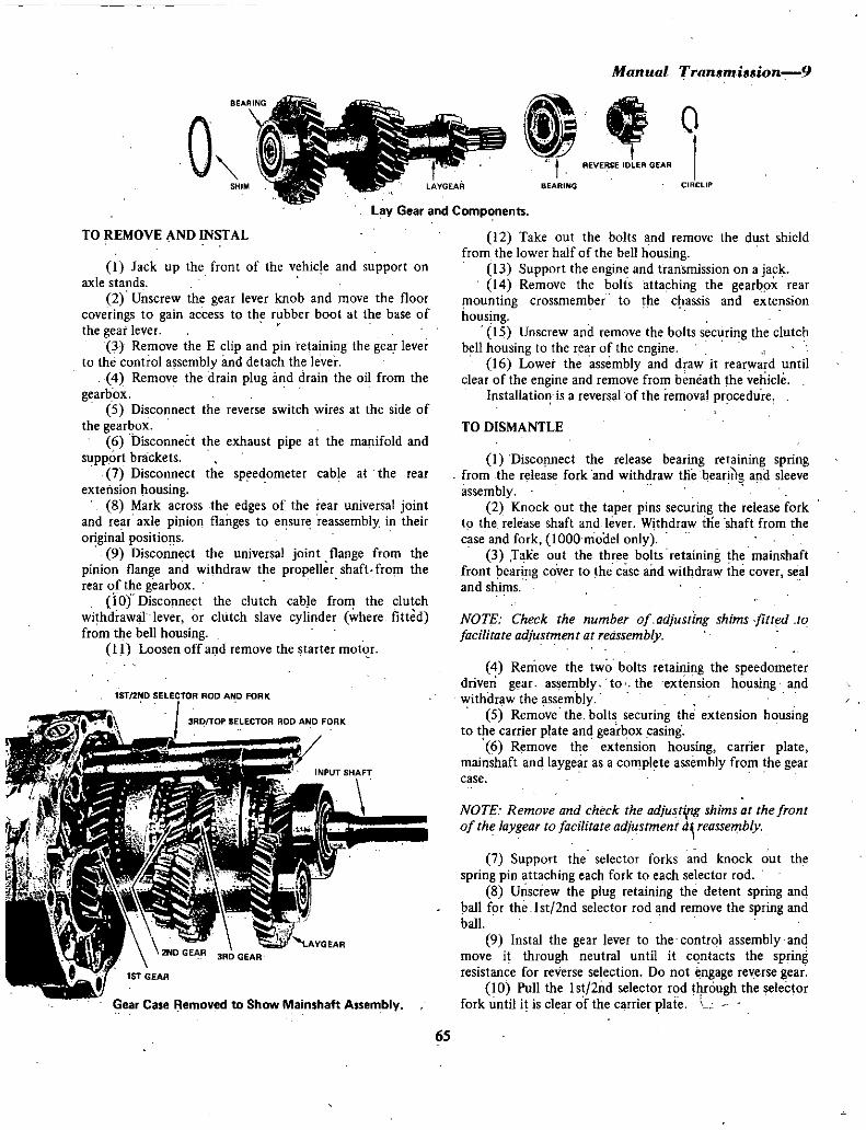
Mannal fransmission 9
1
o
SHIM
REVERSE IDLER GEAR
LAYGEAR BEARING C1RCLlP
L y Gear and Components
12 Take out the bolts and remove the dust shieldfrom the lower half of the bell housing
13 Support the engine and transmission on a jack14 Remove the bolts attaching the gearbx rear
mounting crossmember to the c assis and extension
housing15 Unscrew and remove the bolts securing the clutch
bell housing to the rear of the engineI6 Lower the assembly and draw it rearward until
clear of the engine and remove from beneath the vehicleInstallatio is a reversal of the removal procedure
TO REMOVE AND INSTAL
I Jack up the front of the vehicle and support on
axle stands
2 Unscrew the gear lever knob and move the floor
coverings to gain access to the rubber boot at the base ofthe gear lever
3 Remove the E clip and pin retaining the gea leverto the control assembly and detach the lever
4 Remove the drain plug ilOd drain the oil from the
gearbox5 Disconnect the reverse switch wires at the side of
the gearbox6 Disconnect the exhaust pipe at the manifold and
support brackets7 Disconnect the speedometer cable at the rear
extension housing8 Mark across the edges of the rear universal joint
and re r axle pinion flanges to e sur reassembly in their
original positio s
9 Disconnect the universal joint flange from the
pinion flange and withdraw the propeller shaft from the
rearofthe gearbox10 Disconnect the clutch cable from the clutch
withdrawal lever or clutch slave cylinder where fittedfrom the bell housing
11 Loosen offand remove the starter motqr
lST2ND SELECTOR ROD AND FORK
RDTOP SELECTOR ROO AND FORK
Gear Case Removed to Show Mainshaft Assembly
TO DISMANTLE
I Disconnect the release bearing retaining springfrom the r lease fork and withdraw tHe earitg a d sleeve
assembly2 Knock out the taper pins securing the release fork
to the release shaft and lever Withdraw die shaft from thecase and fork IOOOmoael only
3 TaKe out the three bolts retaining the mainshaftfront earing cover to he case andwithdraw the cover sealand shims
NOTE Check rhe number of adjusring shims fitted to
facilitate adjustment at reassembly
4 Remove the two bolts retaining the speedometerdriven gear as embly to the extension ho sing andwithdraw the assemhly
5 Remove the bolts securing the extension housingto the carrier plate and gearbox casing
6 Remove the extensi n housing carrier platemainshaft and laygear as a complete assembly from the gearcase
NOTE Remove and check the adjusti1g shims ar the fronrofthe laygear to facilitate adjustment d reassembly
7 Support the selector forks and knock out the
spring pin attaching each fork to each selector rod
8 Unscrew the plug retaining the detent spring and
ball for the Ist 2nd selector rod and remove the spring and
ball9 Instal the gear lever to the control assembly and
move it through neutral until it contacts the springresistance for reverse selection Do not ngage reverse gear
10 Poll the Ist 2nd selector rod t ugh the selectorfork until it is clear of the carrier plate
6S

10lI1anual Transnri33ion
NUT1 nsure that the IIlterluck plunger is recJlered If itshould be dislodged from the carrier plate
11 Move the gear lever across to what is normally the1 st 2nd position and retain in this position
2 Carefully tap the extension housing with a
soft faced hammer to disengag i from the carrier platedowels and separate the hous ng from the carrier plateassembly
13 Unscrew the plug retaining the detent spring andball for the 3rd 4th selector rod and remove the spring andball
14 Unscrew the blanking plug for the reverse selectorrod but note that the detent ball and spring cannot beremoved until the rod is withdrawn
15 Tap the 3rdj4th selector rod through the selectorfork and out ofthe carrier plate detach the fork
16 Tap the reverse selector rod through the carrier
plate and out of the selector fork detach the fork
17 Remove reverse selector detent spring and ballfrom the blank ended hole in the carrier plate also
interlock plungers from their respective positions18 Withdraw the reverse sliding gear from its shaft
19 Remove the circlips retaining reverse gear to the
mainshaft and reverse idler gear to the layshaft
GEAR lEVER
BUSH
tCllP
BOSH
SEAl
O rSELECTOR LEVER
t BOLT
CLEVIS PIN
20 Slide both gears from the splines of their
respective shafts21 Using a soft faced hammer tap the rear end of the
mainshaft to dislodge the bearing from the carrier plate It
may be necessary to tap the laygear shaft also to allow the
laygear and mainshaft assemblies to be withdrawn togetherfrom the carrier plate
22 Separate the laygear from the mainshaft and pullthe input shaft from the top of the mainshaft assemblyremove the needle roller bearing if still attached to the
mainshaft spigot23 Remove the thrust washer and ball bearing from
the end of the mainshaft followed by the baulk ringsynchro hub assembly third gear baulk ring and third gearcomplete with needle roller bearing
24 Remove the mainshaft rear bearing and thrust
SPR1NG PIN
tt 1ST lNDSELECTOR ROD
1ST 2ND SELECTOR FO
srRIH I IN
Cf
3RfTOf SELECTOR ROD
IC
3ROTOP SELECTOR FORK 7REVERSE SELECTOR SHAFT
REVERSE SlIOING GEAR
Gear Selector Rods and Forks
1rar
WELCH PLUG
CLEVIS PIN 1 CONTRtOl ROD
EcLIP
EXTENSION HOUSING
Exploded View of Gear Change Control Components
66

Manual Transmissionll
MAINSHAFT i idl i t BAULK RING THRUST WASHER
I G o fA o 4 o 6 bt
VJt RoIGEAR t
THRUST WASHER
It 2ND GEAR Ii
SYNCHRQ AS V
t SVNCHRO ASSY
REVERSE GEAR BEAR1NG
SPACERBAULK RING BEARING
Exploded View of Mainshaft C mponents BUSH IIwasher followed by first speed gear complete with needle
roller bearing spacer and mainshaft bush25 Withdraw from the mainshaft the first gear baulk
ring synchro hub assembly second gear baulk ring and
second gear complete with needle roller bearing26 If dismantling the synchro hub assemblies is
necessary mark one face of the hub and sleeve to ensure
reassembly in the correct order27 Remove the synchro springs from each end of the
hubs and press out the hubs from the sleeves28 If replacement of the input shaft bearing is
necessary remove the circlip and washer and press or drawthe bearing from the shaft
29 To remove the gear change control rod assemblyfrom the extension housing remove the wire locking thecontrol rod selector lever retaining bolt and remove the boltand lever
30 Unscrew the retaining plug and withdraw the
double spring and plunger for reverse selector loading31 Remove the gear lever if not already removed32 Remove the circlip and clevis pin retaining the
control rod assembly to the extension housing and
withdraw the assembly from the housing sleeve33 To separate the control rod from the pivot
assembly it will be necessary Jo remove the expansion plugand push out the control rod
34 If replacement of the oil seal and or themainshaft bush is necessary knock out the componentsfrom the rear of the extension hous ng
Extension Housing Removed to Show Revene Gear Assembly
67
ftCUG
OUTER SPRING
PLUNGER
i
Components for Reverse Selector Loading

0
f
t
J2Manual T arisis ion
TO CLEAN AND INSPECT
l Clean all components in cleaning solvent and blow
dry with compressed airCheck ball bearings for roughness or excessive side
play Do not rotate the bearings at high speed with
compressed air particularly when thebearings are dry or
damage will result
3 Check needle roller bearings for wear imd or
pitting4 Examine the teeth on all gears for wear and or
pitting also for burring on the teeth ends5 Check the synchronising teeth on the gears for
wear or chipping6 Check the baulk rings on their corresponding gear
cones for wear see specific tions7 Check ihe selector forks for wear the selector
detent balls for wear and the detent springs for breakage or
loss of tensjon see specifications8 Renew all worn or damaged components as
necessary
TO ASSEMBLE
I Ir stal second gea nd ne le roller bearing on the
mainshaft with the gear cone facing to the rear of the shaft2 Position the baulk ring on the gear cone
3 If the synchro hub has een dismantled instal the
syrichrci plates in ihelub slots and slide the sleeve over thehub splines so thaI the marks made on dismantliitg are at
the same side
SH FT PLATES
Ex loded View ofSvnchrolii r omponents
4h II
4 Fit the synchro spring under the synchru platelugs at each side to tension the plates
NOTE The svnchrn springs must be installed so thal whenviewed from one side thev travel in opposite directions
5 Instal the synchro hub assembly on themainshaftengaging the ends of the synchro plates in the notches ofthe baulk ring and the hub splines on the mainshaft splines
6 Lubricate and instal the mainshaft bush needleroller bearing and spacer for first gear
7 Engage the not hes of a baulk ring on the synchrohub plate ends and instal the first gear entering the cone
into the baulk ring8 Instal the thrust washer and press the rear bearing
onto the mainshaft9 For the purpose of checking first gear to thrust
washer end float instal the reverse gear and secure with the
circlip Check the end float between first gear and thrustw h er also between second gear and the mainshaft flange
See specifications for end float Clearance
NOTE If end float exceeds the limit renew the thrustwasher and recheck
l0 Remove reverse gear and Circlip on completion of9
11 Lubricat and instal third gear complete withneedle roller bearing to the front of the mainshaft with gearcone facing forwaro
12 Instal a baulk ring to the thrd gear cone
13 If dismantled assemble the synchro hub as
previously described4 Position the synchro hub assembly on the
mainshaft SQ that the synchro plate ends engage the baulkring notches and the hub splines engage the mainshaftsplines
5 lnstalthe ball bearing in the mainshaft recess
grease both faces of the thrust washer and instal so that theoil gronve side of the washer abuts the synchro hub Locate
the notch in the tliIust washer over the ball bearing16 Position the remaining baulk ring so that the
synchro plate ends engage the baulk ring notches17 Lubricate and iris tal the needle roller bearing on
the mainshaft spigot18 If the input shaft has been dismantled press on
the bearing and secure with the washer and circlip19 Position the input shaft on the mainshaft needle
roller bearing and erigage the gear cone in the baulk ringMainshaft assembly is ow completed ready for installation
NOTE Before installation of the laygear and mainshaftassemblies to the carrierplatdi Will be necessary to checkthe laygear end float This is essential particularly if anyparts of the assemb v have beei renewed
As in the three speed gearbox the end float figure is
nomul v found bv use of a special tool for this purpose
68

BAU
uOTRlNG
N
TT
19VI
Manual Tran mi ion 1l
i OydSHIMS CIRCLIP
Exploded View of Input Shaft Components
which should be used if available Alternative v if the tool is
not available the Plastigage method can be used as follows
20 Ensure that the citc1ip is correctly located in the
bearing aperture at the front of the gear case
21 Instal the laygear in the case so that the bearingabuts the circlip
22 Cut three pieces of Plastigage or soft lead wire tofit on the bearing aperture flange in he carrier plate spacethem equidistant around the flange
NOTE To hold the three pieces ofPlastigage or lead wire
in position it may be necessary to use a smear ofgrease
23 Fit the carrier plate into position over the laygearrear bearing and onto the gear case
24 Instal the carrier plate retaining bolts and tightenthem diagonally and evenly to a torque of 12 16 ft lb
25 Remove the carrier plate and carefully detach the
pieces of Plastigage or lead wire from the flange
NOTE Provided the Plastigage or lead wire was ofadequatethickness it should now be in a flattened comjitiolL
26 Using a micrometer check the thickness of each
piece of compressed Plastigage or soft lead wire and arrive
at a mean figure Deduct fr9m this figure the necessaryend float of 0 03 rum 0 001 in and the balance representsthe thickness of the washer required
27 Remove the laygear assembly from the gear case
28 Mount the carrier plate in the jaws of a vice fittedwith protective covers
29 Bring together the laygear and mainshaft
assembly so that the teeth on both are meshed in the
running position30 Insert the mainshaft through the appropriate hole
in the carrier plate and enter the rear bearings of the
mainshaft and laygear in their respective carrier plateapertures
31 Using a soft faced hammer or press seat the
bearings in their apertures
NOTE Ensure that both bearings enter the apertures
squarely and do notallow the gear teeth to unmesh
32 Instal the reverse idler gear to the layshaft and
secure with the circlip33 Instal reverse gear on the mainshaft and secure
with the circlip
34 Instal the reverse sliding gear on its shaft35 Instal the selector forks on the synchro sleeves
and the reverse selector fork on the sliding gear36 Insert the detent spring and ball for the reverse
selector rod in the blank ended hole in the carrier plateUsing a piece of metal rod depress the ball and spring and
hold in this position37 Insert the reverse selector rod through the fork
and carrier plate with the two detents on the selector rod
facing the detent ball
38 When the selector rod engages over the depresseddetent ball remove the holding rod and push in the selector
rod until the ball engages the first detent on the rod Instalthe plug in the detent hole
39 Align the holes in the selector rod and fork andknock in the spring pin to secure
40 Instal the interlock plunger for reverse andthird top selector rods
41 Insert the third top selector rod through thecarrier plate and selector fork with the three detents on the
rod facing the hole in the carrier plate for the detent balland spring
42 Align the centre detent on the rod with thecarrier plate hole and instal the detent ball and springScrew in the retaining plug until it is flush with the plateedge
43 Align the holes in the selector rod and fork andknock in the spring pin to secure
NOTE First second selector rod should not be installed
untilthe extension housing has been fitted
44 Assemble the control rod components to the
extension housing in the reverse order of removal Instal a
new oil seal and expansion plug to the pivot assembly and
locking wire to the control rod selector lever retaining bolt45 Fit the gear lever to the control rod assembly and
move the gear lever to what is normally the first second
position andretain in this position46 Offer the extension housing up to the carrier
plate and engage it on the dowels Use a soft faced hammerand gently tap the housing into position on the carrier
plate47 Move the gear lever across to the reverse position
but do not attempt to engage the gear hold in this position48 Insert the interlock plunger for third tnp and
first second selector rods49 Push the selector rod through the first second
selector fork and into the carrier plate with the three
69

14MaJlUal Transmission
detents on the shaft facing the hole in the carrier plate forthe detent ball and spring
50 Align the holes in the selector rod and fork andknock in the spring pin to secure
51 Insert the detent ball and spring into the carrier
plate and screw in the retaining plug until it is flush withthe plate edge
NOTE The position of the detent retaining plugs regulatesthe amount of rension on the detent balls and springsexcept reverse selectorNormally the tension is correct
when the plugs are screwed in flush with the carrier plateedge
52 Instal the selected laygear end float adjustingwasher to abut the circlip in the front bearing apertureSmear with a little grease to hold in position
53 Instal the carrier plate assembly into the gear case
so that the front bearings of the mainshaft and laygearassemblies enter the bearing apertures squarely Ensure thatthe selector rods enter the support holes in the gearcase
54 Check that the dowel holes and dowels are
aligned in the carrier plate and gear case Use a soft facedhammer and gently tap the carrier plate down into position
55 Instal the retaining bolts and tighten evenlyworking diagonally from one bolt to another to a torque of16 2 2 kg m 12 16 ft lb
56 Using a depth gauge check the dimension fromthe front face of the front bearing outer race to the gearcase front cover face Deduct from the dimension 5 00
515 mm 0 20 0 206 in to allow for the cover bearingretainer boss
The balance is the thickness of shim required for
adjustment57 Instal the selected shim on the bearing outer race
smear a new oil seal with grease and fit to the front cover
58 Position the front cover with gasket ring on the
gear case instal and tighten the retaining bolts to a torqueof 10 1 4 kg m 7 10 ft lb
59 Insert the clutch release shaft through the case
return spring and release fork60 Instal the taper pins to secure the shaft and fork
Position the return spring so that one leg engages over thefront of the fork leg and the other spring leg against thecase
61 Instal the release bearing and sleeve assembly andattach to the release fork by the spring legs
62 Lubricate the speedometer driven gear assemblyand instal in the extension housing with the two retainingbolts
63 Instal the plunger double spring and retainingplug for the reverse selector loading Refit the reverse lightswitch if it has been removed
64 Check that aU geari engage by operating the gearchange lever
65 Instal the transmission to the vehicle and fIll withthe correct grade and quantity of oil
PART 3 PROPELLER SHAFT
DESCRIPTION
The one piece tubular propeller shaft is fItted with twoneedle roller and trunnion type universal joints
The rear yoke of the rear universal joint is flanged and
bolted to the rear axle pinion shaft flangeThe sleeve on the front yoke of the front universal
joint has internal splines which slide on mating splines on
the rear end of the gearbox mainshaft which is supportedon its outer circumference by a bush with an oil seal in the
gearbox rear extension
Oversize circlips are available to compensate for anyend float in the bearing cups
70

TO REMOVE AND INSTAL
l Jack up the rear of the vehicle and support on axlestands
2 Mark across the edges of the rear universal jointand rear axle pinion flanges to ensure reassembly in thei
original positions3 Remove the four universal joint flanges to rear axle
pinion attaching bolts and nuts
4 Withdraw the propeller shaft to the rear and
disengage the front yoke sleeve from the gearboxmainshaft
Insert a spare sliding sleeve in the transmission rear
cover to prevent loss of oil
Installation is a reversal of the removal procedure
TO DISMANTLE AND ASSEMBLE
1 Knock out and remove the two securing circ1ips on
opposed needle roller bearings of the front niversal joint2 Holding the joint in a vice and using a soft metal
drift tap on the end of one of the bearing cups to drive the
other bearing out of the yoke Lift the bearing out with the
Ianllal Transmission 15
fingers to avoid dislodging the needle rollers3 Again using a soft drift tap on the end of the
trunnion of the bearing just removed to drive the other
bearing out of the yoke and again carefully remove to avoid
dislodging the needle rollers4 Manoeuvre the yoke over the ends of the trunnion
and withdraw from the shaft assembly5 Treat the other two bearings of the front universal
joint and the bearings of the rear universal joint in a similar
manner to completely dismantle the propeller shaft6 Check the needle roller bearings and trunnions for
wear I fwear is apparent renew the trunnions and bearingsas a kit Never renew individual needle roller bearingassemblies or fit old bearings to a new trunnion Always use
new bearing retaining circlips and bearing seal washers
Reassembly is a reversal of the dismantling procedure
NOTE When dismantling or reassembling do lIorhold the
machined section of the front universal joint yoke in theunprot cred jaws of a vice or the seal surface of the yokewill be damaged Where necessary reduce any bearing cup
end float bv installing oversize circlips
GEARBOX
PART 4 MANUAL TR1NSMISSION FAUIT DIAGNOSIS
IDifficult gear change
Possible cause
a Maladjustment ofselector mechanism
b Faulty gear synchroniser mechanismc Faulty clutch or clutch release mechanism
d Damaged gear teethe Distorted transmission shaft splines
2 Gear clash on changing down
Possible cause
a Faulty clutch or clutch release mechanism
b Faulty synchro rings and cones
c Broken or incorrect positioning ofsynchrobar retaining springs
d Gearbox lubricating oil too heavy
3 Slipping nutof gear 1st and 2nd
Possible cause
a Weak or broken selector shaft detent springb Worn mainshaft sliding gear or laygear
Remedv
Check and adjust selector mechanism
Overhaul gearboxCheck and overhaul clutch and or adjustrelease me hanism
Renew damaged componentsRenew damaged component
Remedy
Overhaul clutch and or adjust release mechanismCheck and overhaul gearbox renew componentsas requiredCheck and overhaul gearbox renewcomponentsas requiredDrain gear case and refill with correct quantityand grade of oil
Remedy
Renew faulty componentsCheck and renew faulty components
71

16Manual Tran3miuion
c fxcessive end float of laygeard Worn main drive gear or mainshaft ball bearingse Incorrectly adjusted gear change mechanism
4 Slipping out of gear 3rd and Top
Possible cause
a Weak or broken selector shaft detent springb Worn synchro teeth on third or top speedsc Excessive end float of laygeard Worn ball bearings on main drive gear or mainshafte Incorrectly adjusted gear change mechanism
5 Gearbox noise in neutral
Possible cause
a Worn main drive ball bearingb Chipped or pitted constan t mesh gears
laygear main drive gear or 2nd and 3rdspeep mainshaft gearo
c Excessive laygear end floatd Lack of sufficient lubricant
PROPELLER SHAFT
IShaft vibration
Possible cause
a
b
c
d
e
Bent propeller shaftExcessive wearin universal joint trunnionand bearingsPiopeller shaft out of balanceExcessive wear of front joint sleeve in rear
exterision bush hearingRear universal joint to pinion flange bolts loose
2 lxcessive backlash
Possible cause
a Worn univeroal joint trunnion and bearingsb Worn mainshaft and universal joint sleeve
splines
Check and renew faulty thrust washero
Check and renewworn componentsCheck llfld re adjust as necessary
Remedy
Check and renew faulty componentsCheck and re1ew worn componentsCheck and renewworn thrust washersCheck and renew worn bearingsCheck and re adjust as necessary
Remedy
Overhaul and renew bearingOverpaul and renew components as necessary
Check and renew laygear thrust washersDrain and refill gear case with correct quantityand grade of pi
Remedy
Renew shaftRenew complete univeroal joint trunnion
and bearingsRenew complete propeller shaft
Rrnew exteJlsion housing bush assembly
Renew and tighten loose bolts
Remedy
Renew joint trunnion and bearings as assemblyRenew worn components
72

AUTOMATIC TRAN MISSIONSPE IFITlONS
Type Three forward
speeds and
reverse
epicyclic geartrain with torquecooveTtef
Nissan 3N71A
Automatic
hydraulic
Model
Operation
Gear controlIOdo Series1200 Series
Column changeFloor changeT bar quadrant
Gear ratios
LowIntermediate
HighReverse
Lubricant
type
2 4581458IdOO2 182
3N71A Type For equivalent551itres
9750 Imp pistJl750USpts
Total capacity
Shift Speeds 4 111 I Axle ratio
Upshift speeds light throttleLow to intermediate 12 17kph
8 II mph29 34 kph18 21 mph
34 39 kph21 24 mph
55 6034 38 kph
43 48kph27 30 mpli
77 82 kph48 51 mph
71 76 kph44 47 mph
Intermediate to high
Upshift speeds full throtileLow to intermediate
Intermediate to high
Upshift speeds on kickdownLow to intermediate
Intermediate to high
Downshift speeds on kickdown
High to intermediaie
Intermediate to low
Downshift speeds nil tlirottleIntermediate to low
Shift Speeds 3 900 1 Axle ratio
Upshift speeds light throttleLow to iri termediate
Intermediate to high
Upshift speeds kickdownLow to intermediate
Intermediate to high
Downshift speeds on kickdownHigh to iniermediate
Intermediate to low
Downshift speeds nil throttleIntermediate to low
TORQUE WRENCH SEITINGS
Drive plate to crankshaft
Drive plate to torque converter
Oil pan drain plug
Inhibitor switch iotransmission case
Manual shift lock nut
Oil cooling pipe flare nut
Oil cooling pipe connecting nut
Converter housing to engine
I DESiUPTION
The automatic transmission combines a fluid couplingor torque converter with a fully automatic three speedepicyclic gear system The torque converter housing arid the
transmission case are separate casingsThe transmission provides three forward ratios and one
reverse The hydraulic system consists of a single pump and
a valve arrangement
34 39 kph21 24 mph
8 13 kph5 8 inph
1O 18kph6 11 inph14 24kph9 15 mph
35 48kph22 30 mph
80 96 kph50 60 mph
78 88 kph48 55mph24 40 kphI5 25 mph
8 13 kph5 8mph
6 0 kg m
43Ib ft10kg m
7Ib ft
45 kg in
32Ib fl
kg m
8Ib ft4 5 kg m
32lb ftII kg m
81b ft3 0 kg m
21 lb ft
2 5 kg m
18Ib ft
Fiuid level in the transmission is checked by a dipsticktype indicator locaied in the oil filler tube The 1200 Series
gear selector is it floor mounted T bar and quadrantThe speed selector quadritnt adjacent to the base of
the floor mounted selector lever is marked L lock in first
or low 2 drive in I and 2 D drive or direct N
neutral R reveIe and P park
73

2 Automatic Transmission
The following gear selections cannot be made withoutdepressing the spring loaded button on the side of theT shaped gear selector lever P to R R to P D to 2 2 to Iand N to R
n addition a starter inhibitor switch ensures that it isnot possible to start the engine unless the selector lever is inthe P or N position
The 1000 Series gear selector differs from the 1200series in that the gear selection lever is mounted on the
steering column
ENGINE TUNING
When tuning or testing the engine the handbrake must
be firmly applied and the selector lever must be in the P
park or N neutral position otherwise the vehicle willmove forward or backward as the engine speed is increased
When adjusting the idling speed move the selector leverto the D position in order that the correct idling speedadjustmen t may be obtained
If idling speed is too slow the engine will not operatesmoothly If it is too high a shock or crunch develops when
changing from N to D or R
TOWING
For long distance towing the propeller shaft should bedisconnected at the rear universal flange and removed fromthe vehicle and a suitable plug applied to the rear of the
transmission case to prevent loss of fluid or ingress of dirt
TRUNNION
WASHER
I PIfIJ
SELECTOR KEY
CIRCUP
View of the Automatic Transmission Selector ComponentsLower End of SteeringColumn 1000 Models
An alternative method is to tow the vehicle suspendedfrom the rear
The vehicle may be towed for a short distance without
disconnecting the propeller shaft provided the towing speeddocs not exceed 48 kmh 30 mph and the cause for which
the vehicle is being tow J is nut within the trausmissiull ur
the rear axleIt is not practicable to start the engine by either towing
or pushing the vehicle
2 HYDRAULIFLUID
Only a recommended Automatic Transmission Fluidshould be used in the transmission when topping up or
changing the fluid in the system See Specification sectionThe fluid level in the transmission case should be
checked at regular intervals of no greater than 6 500 km
4 000 miles and it is good policy to check the fluid levelat each lubrication service
Every 48 000 km 30 000 miles the fluid should bedrained off while the transmission assembly is at operatingtemperature
Gear Selector level Pivot and Quadrant with Turn SignalSwitch and Top Column Covers Removed 1000 Models
TO CHECK AND TOP UP
1 Place the vehicle on a level t100r and open the
engine bonnet2 Carefully clean around the top of the transmission
case filler tube and dipstick to ensure that no dirt or
foreign matter can enter the filler tube as the dipstick iswithdrawn
3 Check the transmission thoroughly for damp areas
and determine the type of oil present Transmission oil is
readily identified by its reddish colour
4 I is difficult to detemline the exact area from
74

CROSS
STnASSV
DISHED WASHER
DUST BOOT SPRING
I IJl12QlD
a
WASHER
rDISHED WASHER
TRANSMISSION LINK
Automatic Transmission lBUSH
ISUPPORT RACKET
II
STEERING COLUMN TUBE
BRACKETINSERT WASHER BRACKET SCREW
CONTROL TUBE 1 l fLJ
t11lIIIIlIIlIII@ Lj
y t LAMP ASSVCI
ADJUSTING NUTSSPRING 1
IPIN QUADRANT INDICATOR
J aE CLIP
BUSH
ADJUSTING THREAD
Exploded View of Cross Shaft Assembly and linkageComponents Automatic Transmission 1000 Models
which the fluid is escaping However by checking in the
following sequence it can be determined from what aveoue
the oil is escapingShould oil be leaking from the converter housing the
oil could be emitting from the pump housing holes in the
pump external wall or the oil seal of the engine crankshaftIf the rubber ring fitted to the oil pump housing is
defective it will allow the oil to seep out onto the external
walls of the converter housing5 To determine accurately the areas from which the
oil is escaping wipe the transmission assembly thoroughlyand remove the dust cover from the converter housingHaving removed the dust cover wash the area clean
6 Bring the oil to normal operaiing temperaturethen select D or R to increase the oil pressure and examine
the torque converter housing for leakage7 Clean the area where the transmission body is
coupled to the extension housing Select the D or R
position and with the transmission fluid under pressureexamine the elbow connector oil pressure inspection hole
and the gasket between the transmission body andextension housing for leakage
8 Should the vacuum diaphragm be damaged this
can be readily detached by checking the emission of smoke
at the rear end of the exhaust pipeIf white smoke is emitting from the exhaust pipe this
indicates a damaged diaphragm allowing the transmission
fluid to be drawn up into the manifold and dispensedthrough the exhaust system
A damaged diaphragm will
consumption of transmission fluid
wear
result in excessive
and premature engine
WIRING
U Exploded View of Automatic Trans
mission Selector Components Upper End
of Steering Column 1000 Models
Replace the defective vacuum diaphragm immediately9 Check and top up the fluid in the following
manner Place the selector lever in the P position and firmlyapply the handbrake
10 Start the engine and run at a fast idle to bring the
engine and transmission to normal operating temperature
NOTE Alternatively run the vehicle on the road forapproximately five miles
II Return the engine to the correct idling speedwithdraw the dipstick and check the level of the hydraulicfluid If necessary add sufficient fluid to the transmission
case via the filler rube to bring the level to the FULL mark
on the dipstick
NOTE Use a recommended automatic transmission fluidonly do not overfill or foaming and unsatisfactoryoperation of the assemblv will result
75

4Automatic Transmission
1 I Replace the dipstick in thc tiller tube ensuringthat no dirt or dust can enter the transmission case
TO DRAIN AND FILL
I Bring the transmission to the nonnal operatingtempera LUre and raise the vehicle on a hoist or place it overa pit so that the transmission case is reasonably level
2 Unscrew and remove the transmission case oil pandrain plug and drain the hydraulic fluid into a suitablecontainer
rOTE Excn ise extreme cauriun Htzen Jrallling llie fluidafter a long nm as scalding could result
3 Replace and tighten the oil pan drain plug to the
specified torque4 Refill the transmission case with the correct grade
and quantity of fluid as recommended start the engine and
bring it to the normal operating temperature5 Check the fluid level on the dipstick and top up if
necessary as detailed in TO CHECK AND TOP UP
3 TRANSMISSION SELECTOR LlNKA4 E
TO ADJUST
LEVER
IA
SELECTORQU ADRA NT
1r
iclE
AND PARK BL PIN
LEVER BRACKET dIWIRE
J
i
1 Raise the front of the vehicle and support on
stands
2 Check the position of the gear indicator in relationto the actual selected or detent position on the transmission
by selec ing either P park or L low3 When either of the gears are selected a slight
perceptible drag is experienced during the change patternthis indicates that the manual valve is correctly positionedin the detent position in the valve body and that the lever is
correctly aligned4 Check position of the gear indicator when released
in relation to the relevant position on the plate5 Should adjustment be necessary raise the bonnet
and working from inside the engine compartment 1000Models only adjust the linkage Prior to carrying out
adjustment select position 0 on the gear indicatormounted on the steering column
NOTE all 1200 Models with Tbar floor shift the
adjustment point on the link rod is accessible from belowthe eizicIe
Adjust the linkage so that the detent position D
corresponds with position 0 on the indicator platequadrant
View of Selector Lever Showing Reverse and Park BlockingPin and Method of Locking the Lever Bracket Grub Screw
FloorChange Systell 1200 Models
4 NEUTRAL SAFETY SWITR
The neutral safety switch incorporating the reverse
light switch is attached to the right hand side of thetransmission case The black yellow wires of the switch are
connected with the starter inhibitor switch to ensure thatthe engine can only be started with the transmission ineither the N neutral or P park positions
The two red black wires of the switch are connected inseries with the reverse light which should only operatewhen the R reverse position is selected 011 the selectorquadrant
Any adjustment to the transmission linkage should befollowed by the neutral safety switch adjustment
TO ADJUST
1 With the engine stopped disconnect the remotecontrol lower rod and position the gear selecting lever at Nneutral un the side of the transmission case
It will be noted that the parallel flats on the switch
76
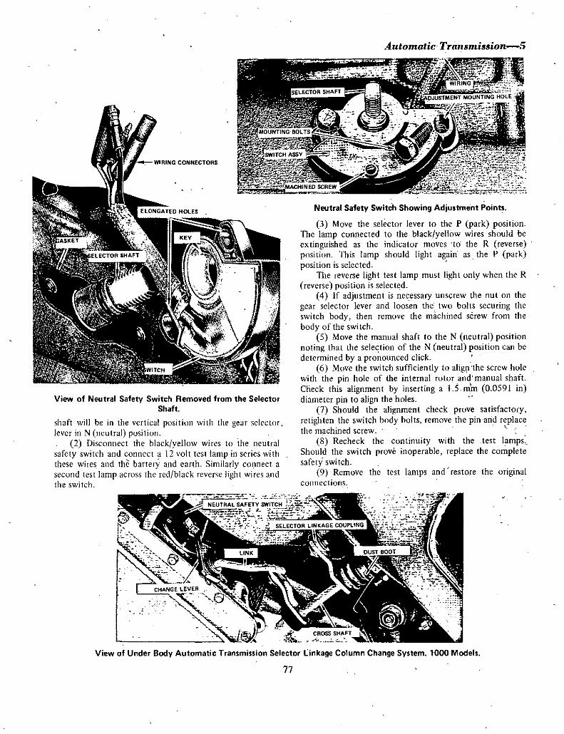
Automatic Trallsmission 5
WIRING CONNECTORS
View of Neutral Safety Switch Removed from the SelectorShaft
shaft will be in the vertical position with the gClf selector
lever in N neutral position2 Disconnect the black yellow wires to the neutral
safety switch and connect a 12 volt test lamp in series with
these wires and the battery and earth Similarly eOJmeet a
second test lamp across the red black reverse light wires and
the switch
Neutral Safety Switch Showing Adjustment Points
3 Move the selector lever to the P park positionThe lamp connected to the black yellow wires should be
extinguished as the indicator moves to the R reverse
position This lamp should light again as the P parkposition is selected
The reverse light test lamp must light only when the R
reverse position is select d
4 If adjustment is necessary unscrew the nut on the
gear selector lever and loosen the two bolts securing the
switch body then remove the machined screw from the
body of the swi tch5 Move the manual shaft to the N ncutral position
noting that the selection of the N neutral position can be
determined by a pronounced click
6 Move the switch sufficiently to alig1 the screw hole
with the pin hole of the internal rotor and manual shaft
Check this alignment by inserting aU mm 0 0591 in
diameter pin to align the holes
7 Should the alignment check prove satisfactoryretighten the switch body bolts remove the pin and replacethe machined screw
8 Recheck the continuity with the test lampsShould the switch prove inoperable replace the completesafety switch
9 Remove the test lamps and restore the originalconnections
View of Under Body Automatic Transmission Selector linkage Column Change System 1000 Models
77

6oAutomatic Tran mission
View of the Under Body Automatic Transmission Selector Linkage Floor Change System 1200 Models
5 KIKDOWN SWITII AND DOWNSHIFT SOLENOID
TO CHECK AND TEST
I Turn the ignition key to the ON position and pressthe accelerator pedal fully
2 During the pressing of the pedal the electricalcircuit between the kickdown switch and the solenoid is
completed When the circuit is completed a click is emittedfrom the solenoid
3 Should the solenoid fail to emit a click during this
operation or the gear change speed be higher than specifiedcheck the following components with suitable electrical test
equipment4 Test the kickdown switch for internal shorting out
5 Test the downshift solenoid for internal shortingout and faulty connections
6 Check the wiring connecting the kickdown switch
to the downshift solenoid for continuity7 Replace defective components where necessary If
the solenoid is to be replaced the torque converter shallhave to be partially drained
8 Drain off approximately I litre I 750 Imp pts2 125 US pts fit the new solenoid and replace the same
amountof oil as drained from the torque converter
View of Brake Pedal and Accelerator Pedal Showinglocation of Automatic Transmission Kick Down Switch
1000 Models
78

6 STALL TEST
Aittomatic Tran mi ionC7
SELECTOR
jWRl
R t E
I6 iI BOSH
fi 7PIN tff 1iil
t iDISHED WASHER d PIN LEVER BRACKET
PIN
b SCREW
ECLlP l
I ECLlP
SPRING I
The stall test is performed in I low 2 intermediateD drive and R reverse range at full throttle to check
engine performance converter clutch operation or
installation and the holding ability of the forward clutch
reverse clutch and low band
NOTE While perfonning this test do not hoid the throttleat full opning for more than ten seconds at a time
Prior to carrying out the tests bring the engine and
transmission to nonnal operating temperature by placingthe transmission in P park arid running for severalminutes
I Check the transmission oil engine oil and radiator
Top up where necessary2 Chock all wheels and apply the parking brake
firmly3 Connect the tachometer to the engine and mount
tre tachometer where it is plainly visible from the driver 5
seat
4 Mark the tachometer at 1700 rpm 1 100 rpm on
the dial
5 Apply the foot brake and shift the selector lever toI 2 D and R r ges successively and at ach range pressthe accelerator pedal gradually and note the engine speedrpm
When the accelerator pedal is fully compressed the
iII
OISHEO WASHER iBUSH PlN f @O a ul
Ij
WiASHE BUSH
@amll1 t
SPRING BOOT
LINK
WASHER
BlitH I@ G
WASHER
IPIN O@
DISHED WASHER
engine speed will become constant and this speed is calledthe stall point at which the engine speed should be noted
The speed should be ihe same in all ranges and shoold be
between 1950 and 2000 rpm
NOTE Having tested one range and prior to testing the
next range place the transmission in Nand nm at
approximately 1200 rpm for one or two minutes to cool
the torque converter oil
6 If the stall point is the same in each range but
below the specified rpm the following defects may be
present a The engine output is inadequate Check thethrottle valve in the carburettor for full throttle opening in
relation to accelerator pedal movement b The stator one
way clutch may be slipping in the converter7 When the stall point exceeds the specified figure
band or clutch slippage is apparent depending on the range
selected8 Excessive engine speed in I 2 and D indicate that
the rear clutch is slipping9 Excessive engine speed in 2 and D and normal rpm
in 1 the one way clutch is slipping10 Excessive engine speed in R only indicates that
the front clutch or low and reverse brake is slipping
j
LEVER
BUSH
o @ 0
T Co Gj TBARTRUNNION
Exploded View of the Automatic Gear Change linkage 1200 Model
79

8Automatic TrarumilJlJion
I I When the stall test speeds are the same in everyrange but above 2100 rpm and discharge pressure from the
oil pump is normal and there is no slippage of clutch or
band the following defects mav be present a Low oil
level in the torque converter b Oil circulation to theconverter has ceased thus allowing the generation ofsteamand air inside the converter c Air in the transmission
fluid due to overheating of the oil
TO CHECK AND TEST
7 LINE PRESSURE TEST
I Should the transmission performance indicate
slipping of the clutch band and brake or incorrect speedsduring gear change check the line pressure
2 To cheCK the line pressure remove the plugs and
connect the line pressure gauge to the measuring points Inthe rear flange
3 Commence the line pressure measurement at idle
speed and check by stages through to throttle range4 High throttle pressure results in excessive speeds
and a sharp thump or shock during the chariging up process5 Leaking spool valve or gear trains result in slipping
or faulty transmission performance6 With the line pressure gauge titted to the
transmission carry out a slow idling line pressure test for thelilll gear range
Should low idling pressures exist in all ranges namelyR P I 2 and D this condition can be caused by a
defective pressure supply system or insufficient power dueto a worn oil pump a sticking regulator valve or oil pressureleak in the valve body or case or an oil pressure leakage inthe oil pump
7 Select ranges I 2 and D and check the linepressure at low i le
Should the readings in the three respective ranges bebelow those readings specified and pressure reading in R iswithin the specified range the cause of the lo pressure
reading can be attributed to oil leakage in the governor andrear clutch
8 Select positions R and P and check the linepressure Ifthe pressure reading is below that specified and
on selecting I 2 and D and finding that the pressures are as
specified it can be determined that the loss of pressure in Rand P is due to oil leakage in the low and reverse brakecircuit
9 High idling line pressures are caused by increasedline pressures due to sticking regulator valve and increasedthrottle pressure due to vacuum tube or diaphragm leakage
10 To measure the vacuum leakage remove thevacuum pipe and measure the negative pressureimmediately the pipe is removed
d 1 A defective or punctured diaphragm can bedetermined by the emission of white smoke from theexhaust pipe If the diaphragm is damaged replaceImmediately as a damaged diaphragm will drain the oil fromthe transmission via the manifold
12 Checking of line pressure iitcrease should becarried out in conjunction with the STALL TEST Using a
vacoum gauge with a range from 0 rum Hg 300 rum Hgcarry out the necessary tests
13 Should the line pressures fail to increase with thevacuum decreasing then check the vacuum rod connection
14 Faulty line pressures are due mainly to a defectivepressure regulator valve plug or pressure regulating valve
View of Automatic Transmission with Oil Pan Vacuum Diaphragm Assembly and Down Shift Solenoid Removed
80

Automatic Tran3mi33ion 9
LINE PRESSURE SPECIFICATIONS
Gear Throttle Opening Low Speed 15 kph High speed 35 kphRange 93 mph and below 217 mph and above
Metric English Metric EriglishFull throttle 10 kg cm2 i421b in2 6 kg cm2 85 Ib in2
Half throttle 7 kg cm2 991b in2 4 8 kg cm2 681b in2
Minimum throttle 3 5 kR cm2 49 Ib in2 3 5 kg cm2 491b in2
2 Full throttle 10 kg cm2 l42lb in2 6 kg cm2 851b in2Half to
minimum throttle 93 kg cm2 132Ib in 5 7 kg cm2 811b in2
D Full throttle io kg cm2 1421b in2 6 kg cm2 851b in2
Half throttle 7 kg cm2 991b in2 4 8 kg cm2 681b in2Minimum throttle 3 5 kg cm2 491b in2 3 5 kg cm2 49lb in2
R Full throttle 15 kg cm2 2131b in2Half throttle 10 7 kg cm2 152 Ib in2Minimum throttle 54 kg cm2 76lb in2
TO REMOVE
8 TRANSMISSION ASSEMBLV
I Raise the vehicle and support on stands disconnect
the earth lead at the battery terminal and the lead at the
terminal on the starter solenoid switch
2 Disconnect the wiring connecting the kickdown
switch to the downshift solenoid
3 Disconnect the accelerator linkage at the
carbu ret or
4 Discoitnect the lower shift rod from the manual
control lever
5 Disconnect the cross shaft from the transmission
assembly6 Unscrew and withdraw the speedometer cable
7 Take out the drain plug and drain off the oil into a
clean container for further use
8 Disconnect the vacuum tube and remove the inlet
arid outlet oil cooling pipes9 Disconnect the exhaust outlet pipe at the
manifold
10 Disconnect the propeller shaft at the rear
universal flange withdraw the propeller shaft from the rear
of the transmission and remove the shaft assembly from thevehicle Plug the rear end of the transmission to prevent
ingress of dirt
NOTE To preserve the original balance of the propellershaft mark across the joint and pinion flange to ensure
replacement in the original positions
II With suitable protection on the Ijack head
support under the transmission case and remove the
transmission supporting crossmember from the und rbodyand from the gearbox
12 Disconnect the wires to the starter safety switch
on the side of the transmission noting the correct positionof the wires for reassembly
13 If installed disconnect the reversing light earthwire froin under the appropriate gearcase to extension
housing bolt
14 Take out the securing bolts and remove thestarter motor then remove the torque converter dust cover
15 Working through the aperture for the starter
motor rotate the crankshaft as necessary and mark the
drive plate in relation to the torque converter plate thenprogressively slacken off and remove the drive plate t
conveiter bolts
16 Sopport the engine with a suitable jack using care
not to damage the sump
17 Progressively slacken off and remove the eightbolts connecting the torque converter housing to the
engine
NOTE Ensure that the transmission is supported on alld
secured to a suitable jack so that it cannot become
dislodged as it is withdrawn from the vehicle Ensure rhat
the jack does notdamage the transmission oil panI
18 Lower the transmission assembly slightly and
remove the dipstick assembly Carefully withdraw the
assembly rearwards to clear the converter from the plate
NOTE Exercise extreme cautioil when withdrawing the
assembly to ensure that the torque converter does not
become dislodged from rhe front of the transmission
Attach a suitable retaining strap to the converter
housing bolting ir ro the housing cover halts so that it
retains the converter in position when the transmission is
withdrawn from rhe rearof the engine
81

1tiA utomalic fran mission
19 Lower the jack supporting the transmission
assembly and withdraw it from the vehicle
TO INSTAL
Installation is a reversal of the removal procedure with
particular attention to the following pointsI Ensure that the converter is fully engaged in the
front of the transmission and in the spigot in the rearof the
crankshaft2 Ensore that the attachment faces of the torque
converter housing and the rear of the engine crankcase are
perfectly dean and free of any burrs
3 Instal the bolts securing the converter to the drive
plate and tighten evenly to the specified torque4 Tighten the bolts securing the converter housing to
the rear of the engine to the specified torque5 Fill the transmission with the specified grade and
quantity of the recommended hydr ulic fluid6 Check and if necessary adjust the selector linkage7 Check the neutral safety switch and kickdown
switch Replace ifnecessary
8 Road test the vehicle and recheck the hydraulicfluid level as described in HYDRAULIC FLUID TO
CHECK AND TOP UP
IEngine will not stari in P or N
9 AUTOMATIC TRANSMISSION FAUI T DIAGNOSIS
Possible cause
a Incorrect selector linkage adjustmentbj Defective inhibitor switch or wiring
c Faulty ignition switch or starter motor
2 Engine starts in D or R range
Possible couse
a Incorrect selector linkage adjustmentb Defective inhibitor switch or wiring
3 Harsh engllgement N to D
Possible cause
a Engine idling speed too highb Faulty vacuum diaphragm or pipec Throttle pressure too high
d Contrf1 valve sticking or faulty
4 No drive in D operates in other ranges
Possible cause
a Incorrect selector linkage adjustmentb Throttle pressure too high
c Control valve sticking or faulty
Remedy
Check and adjost linkageCheck switch and wires adjust or renew
switch as necessary
Check and repair or renew switch or starter
Remedy
Check and adjust linkageCheck switch and wires adjust or renew
switch as necessary
Remedy
Check and adjust idling speedCheck and renew faulty componentsCheck throttle pressure and regulatorvalve and plugFree up or renew control valve
Remedy
Check and adjust linkageCheck throttle pressure regolator valve
and plugFree up or renew control valve
82

5 No drive in R operates in other rangespoor acceleration
Possible cause
a Low fluid level in transmission
b Selector linkage requires adjustmentc Low thr tt1e pressured Control valve sticking or faulty
6 Slipping in all ranges
Possible cause
a Low fluid level in transmission
b Selectorlinkage requires adjustmentc Low throttle pressured Transmission fluid foaminge Control valve sticking or faulty
7 No upshift in D range
Possible cause
a Incorrectly adjusted selector linkageb Faulty vacuum diaphragm or pipingc Fault in shift solenoid and kickdown
switch wiringd Faulty governor valve servo or control valve
e Fluid level low or fluid foaming
Automatic Tranllmullion ll
Remedy
Check and top up fluid level
Check and adjust selector linkageCheck pressure and regulator valve and plugFree up or renew control valve
Remedy
Check fluid level and top up
Check and adjust linkageCheck pressure regulator valve and plugChange to recommended brand of fluid
Free up or renew control valve
Remedy
Check and adjust linkageCheck and renewdiaphragm or pipingCheck and renew or repair wiring
Renew governor valve overhaul servo
Drain and refill with recommended grade and
quantity of fluid
83

1000 MODELS
TypeRatio
SedanStation Sedan
Number ofcrown wheel and
pinion teeth4 111 1 ratio
4375 I ratio
Bearing typeDrive pinion
Dimension pinion head to
crownwheel centre
Bearing pre load
Thickness range of selective fit
shims pinion height adjustment
Thickness range of selective fit
washers bearing preload adjustment
Thickness range of selective fit
spacers bearing preload adjustment
CrownwheelBacklash between crownwheel
and pinion
Maximum run out at crownwheelface
Carrier earingsStandard width
Thickness range of adjusting shims
REAR AXLESPECIFIATIONS
Hypoid
4 111 I4375 I
37 935 8
Tapered roller
45 0 mm
I 772 in6 8 kg cm
5 2 6 9Ib in
0 05 0 50 mm
increments
0 002
0 020 in
increments
230 2 60 mm
increments of0 02 mm
0 09 0 10 in
increments of
0 0008 in
5 75 mm
0 226 in
6 00 mm
0 236 in
6 25 mm
0 246 in
0 10 0 15 mm
0 004
0 006 in
0 08 mm
0 003 in
17 5mm
0 69 in
0 05 0 50 mm
increments
0 002
0 020 in
incremen 1s
Side gearsThickness range of thrust washers
Gear to thrust washer clearance
0 76 0 91 mm
increments of0 05 mm
0 030 0 036in increments
of 0 002 in
0 1 0 2 mm
0 004
0 008 in
TORQUE WRENCH SETTINGS
Maximum SettingsDifferential carrier to axle housing
Propeller shaft flange nuts
Pinion nut
Crownwheel bolts
Carrier bearings cap nuts
1200 MODELS
TypeRatio
Sedan and coupeStation se an and van
Number of crownwheel and
pinion teeth3 900 I ratio
4 III ratio
Bearing typeDrive pinion
Dimension pinion head tocrownwheel centre approx
Preload with new bearingsand oil seal initial
Preload with used bearingsand oil seal initial
Preload with new bearingsbut without oil seal initial
85
2kg m
14 5 ft lb2 5 kg m
18 ft lb
14 17 kg m
101 123
ft lb3 5 kg m
25 5 ft lb5 kg m
36 ft lb
Hypoid
3 900
4 111
39 10
37 9
Tapered roller
45 0 mm
I 772 in
7 9 kg cm
6 1 7 8
lb in
4 5 kg em
3 5 43
lb in
6 8 kg cm
5 2 6 9
lb in

1 1c
2Rear Ask
Preload with used bearings butwithout oil seal initial 3 4 kg em
2 6 3 5
Ib in
Thickness range of selective fitwash rs trinioheight adjustment 2 743 25 mm
increments o f0 03 mm
0 108 0 128
in incrementsof 0 0012 in
Crownwheel
lacklash between rownwheel andpinion 0 10 0 15 mm
0 004
0 006 in
Maximum run out at crownwheelface 0 05 mm
0 002 inCarrier bearings
Standard width 17 5mm0 69 in
0 05 0 50 mm
increments0 002 0 020
increments
TIrickness range of adjusting shims
j
Side gearsThickness range of thrust washers 0 76 0 91 mm
increments of0 05 mm
0 030 0 036
incrementsof 0 002 in0 1 0 2 mm
0 004
0 008 in
Gear to thrust washer clearance
TORQUE WRENCH SETTINGS
Maximuin settingsDifferential carrier to axle
housing nuts 25 kg m
18 ft lb10 kg m
72 ft lb
2 7 kg m
19 ft ID12 17kg m
87 123 ft lb
7kg m
50 ft lb
6kg m
43 ft lb
Oil filler plug
Propeller shaft flange nuts
Pinion nut
Crownwheel bolts
Carrier bearing cap bolts
PART I REAR AXLE IOOO MODELSJ DESCRIPTION
2 DIFFERENTIAl ARRIER ASSEMBI Y
4 Remove the nuts retaining the brake backing platesto the axle casing through the holes provided in the axleshaft flange
5 Withdraw each axle shaft assembly from the axlecasing using a slide hammer and adaptor if necessary
6 Take out the oil drain plug and drain thedifferential oil into a suitable container
7 Mark across the flanges of the pinion and rear
universal joint take out the four securing bolts and nuts torelease the propeller shaft
if
The rear axle is a semi floating type with hypoid finaldrive gears mounted in a detachable carrier
The crownwheel and differential case assembly is
supported in the carrier by two tapered roller bearings thebearing preload and crownwheel backlash is adjusted bymeans of shims
The drive pinion is supported in the carrier by twotapered roller bearings which are adjusted for pre load by a
wJSher and spacer installed between the linion sllOlderand the front bearing inner cone assembly
Pinion height in relation to the crownwheel iscontrolled by shims located between the rear bearing outercone and the carrier
o 7
TO REMOVE AND INSTAL
I Raise the rear of the vehicle and support on axlestands
2 Loosen off and remove the rear wheels and brakeIrunis
3 pisconnect the handbrake cables and hydraulicbrake pipes at the rear of the brake backing plates Plug thepipes to prevent the loss of fluid and entry of dirt
ito
Axle shaft bearings are the pre lubricated ball typewhich require no lubrication in service and are retained to
the shafts by means of collars End float in the axle shaft
assembly is adjusted by shims located at the brake backingplate
With the removal of the axle shafts the differentialcarrier assembly can be detached from the axle without
removing the axle casing from the vehicleIt is important to note thatadjustritent figures stamped
on the fin al rive c9mpOn n s are irl1nits of O opl j ch
which must be taken into consideration when calculatIngthe various differential and pinion adjustments
86

0 OUTER CONE
THRUST WASHER
o i o DIFFERENTIAL CASE
CROWNWHEEL
M 00
c DRIVE PINION
LDCK PIN IPINION SHAFT rj
a SIDE GEAR
O THRU TWASHERHIM
EA
T R CONE
8 Remove the nuts retaining the differential carrier
assembly to the axle casing and withdraw the assemblyInstallation is a reversal of the removal procedure but it
will be necessary to bleed the brake hydraulic system
TO DISMANTLE
NOTE Before dismantling the assembly carry out the
following checks The information gained from the checks
will prove helpful when assembling the unit
a Check the tooth contaci of th ctownwheel and
pinion by applying a thin coating of red lead and engine oilto both sides ofSix or eight of the crownwheej teeth
b Roiate the pinion both ways placing a bar
between the differential case and the carrier tn apply a loadto the gear teeth and so obtain a good marking If the
pinion height bearing pre load a d backlash are correct the
area of contact should be as shown in the teeth markingillustration
c The margin ab6ve and below the area of contacishould be the same and the contact margin should run
approximately three quarters of the tooth length check the
patterps on both sides of the toothd Moont a dial indicator gauge on to the differential
carrier housing so that the plunger is in contact with and at
right angles to the heel of a crownwheel tooth then zero
the dial gaoge
e Hold the pinion firmly and rock the crownwheel
back and forth to check the backlash on the dial gaugeCheck the backlash at approximately three positionsaround the crownwheel Backlash is correct when withinthe imits of0 1 0 0 15 mm 0 004 0 006 in
NOTE Having completed the foregoing checks dismantlethe assemblv as follows
1 Remove the carrier bearing cap nuts and detach the
caps Check that the caps are marked in relation to hecarrier to ensure installation in their original positions
Rear A xle3
FLANGE WASHER
BEAI NG
fIt1o
IWij 91t
OUTER CONE OilSEAL NUT
Exploded View of Differential Final Drive Componen
2 Lift out the differential assembly from the carrier
but ensure th at the bearing outer cones are kept with their
respective bearings
NOTE To facilitate assembly carry aut the followingcheck
a Using a pre load measuring gaugeor spring scale
and cord check the torque required to rotate the pi iO1 at
the flange end Torque required should be within the1imits
of 4 5 kg cm 3 5 43 jn lb Note the reading3 wiih the pinion fl ange held to prevent it from
turning re ove the flange retaining nut3ld wa hef
4 USing a suitable puller withdraw the pinion fl nge
from the end of the pinion shaft5 Using a soft metal drift tap the pinion s aftwith
rear bearing inner cone assembly wash r and bearing spacer
out of the differential carrier housing6 Workirig through the rear bearing outer tp drift
out the front bearing inner cone and rollers and the pinionflange oil seal
NOTE Unless replacement of the pinion taper bearings is
intended do not remove the taper bearing outer cones fromthe carrier
Provided replacement of the pinion is not required do
not remove the rear bearing inner cone assembly from the
pinionIf however replacement ofone or both of the above is
required continue dismantling as follows
7 Using a suitable puller or a press remove the rear
taper bearing inner cone assembly from the pinion8 Draw or press the taper bearing outer cones from
the carrier takirig particular note of the pinion height
87

4Rear Axle
OI
DRIVE PINION OUTER CONE
WASHER BEARING FlANGE NUT
0I 5 Jn
I II tSPACER OUTER CONE OIL SEAL WASHER
Expldded View of Drive Pinion Components
adjusting shims located between the rear outer cone andcarrier
NOTE Beiore dismantling the differential check the camer
bearings at each end of the differential case Provided thebearings are fit for further service do not remove fromtheirposition
9 Mark the position of the crownwheej in relation tothe differential case
10 Release the locks from the crownwheel retainingbolts and remoVe the bolts and crownwheel
II Knock out the differeniial shaft lock pin from thecrownwlieel side of the differential case
12 knock out the differential shaft and remove the
pinions iuid side gears together with the thrust washers
NOTE It is important that each pinion and siLle geartogether with its thrUst washer is marked in relat on to thedifferential case to ensure original installation on assembly
1 3 If necessary for bearing replacement or bearingpre load or backlash setting use a suitable puller and drawhe carrier b arings rbro each side of the differential case
Noie ihe adjusting shims between the bearing and case
TO CLEAN AND INSPECT
I Wash all components in a cleaning solvent andblow dry Vith compressed air
2 Check the crownwheel and pinion for wear pittingor damage
NOTE Crownwheel and pinion are supplied as matchedsets o ly therefore damage to one item requires the
replacement ofboth
3 Check the differential carrier bearings for wearpitting or damage If a bearing is faulty renew the completebearing c9rnprisi g inIer cone rollers and outer cup
4 Check the pinion taper bearings and renew asdesciibed in 3
5 Examine the difTerentialpinion and side gear teethand thrust faces foi wear pitting or damage Check that thethrust washers are in a serviceable condition
6 Check the differential shaft for wear pitting or
damage Replace parts listed in 5 and 6 if not in
serTiceable condition
7 Examine the differential case for damage and or
distortion and renew if necessary Check also the pinionand side gear thrust faces in the case for wear and or
pitting8 Ensure that all shims and spacers are free of
damage
TO ASSEMBLE AND ADJUST DRIVE PINION
Where the old pinion and bearings are serviceable andthe tooth contact turning torque and backlash checksmade on dismantling are satisfactory then assembly is a
reversal of the dismantling procedureIf any of the above factors proved incorrect on the
check it will be necessary to carry out the appropriateadjustment as described in this section
This is not the case however when a new pinion and
crownwheel is to be installed and or the bearings renewed
Adjustment of the pinion positiori and bearing pre loadthen becomes essential
There are two methods of obtaining the correct pinionposition which is regulated by the shims located betweenthe rear bearing outer cup and the carrier One methodrequires the use of an arbor and gauge kit to calculate the
thickness of shim required The second method entails the
alteration of the existing shims thickness to comperisate forthe new pinion head variation using the old pinion headvariation as a guide
Note that the pinion head variation from standardfigures is given in units of 0 00 I in
To Adjust Pinion PositionMethod I With special tools
1 Instal the front and rear bearing outer cones withoriginal shims to the carrier
2 Instal ihe rear bearing inner cone assembly to the
dummy pinion3 Fit the dummy pinion to the carrier and instal the
front taper bearing and the pinion flange
NOTE Do not instal the bearing pre load spacer alld
washer at this point
l4 Instal and tighten the flange retaining nut until the
88

Rear A le5
CrQWnwheel and Pinion Mating Numben and Pinion HeadVariation from Standait Units of 0 001 in
correct initial turning torque of the pinion is obtained see
specifications This should be checked with pre load
measuring gauge or spring scale arid cord
5 Mount the arbor into the differential case carrier
bearing bores so that the gauge rod is directly over the
pinion head
6 Using feeler gauge check the clearance between
the pinion head and the tip of the gauge rod and note th
measurement
7 Calculate the thickness of shims required to obtaincorrect pi ion positIon from tfte following equ tion
W N H x 0 001 0 008 T inches
DefinitionW thickness of adjusting shims fitted
N clearance figures obtained in 6 with feeler gauges
Ii pinion head variation figure on the pinion head
T thickness of shims required to correctly positionp pion
Examplew 0 010 in
N 0 004 inH I
Therefore0 010 0 004 I x 0 001 0 008 0 007 in
Thickness of shims required to correctly position pini9D j
0 007 in 0 178 mm
8 Remove the dummy pinion assembly from thecar ier and withdraw the rear bearilg outer cone and o
adjusting shims from the carrier
9 Instal the shims as calculated to the carrier and
refit the rear bearing outer cone
To Adjust PiniQn PositionMethod 2 Without pecial tools
In the event of the arbor and gauge kit not beingavai1 ble it will be necessary tQ use the shims removedfom
behind the re r bearing o ter cone plus or minus as thecase may be the figure etched on the new pinion as a
starting point foi pinion position adjustment This method
ofadjus ment entails asseini ling the pinion and adjustingpillion bearing pre load fitting crownwheel and differential
a sembly and adjusting the backlash and iaking t th
markings with red lead or engineers blue This is it trial anderro method unt sat sfactory arking is o tained
If a new crownwheel and pinion are to be fitted withthe old pinion bearing it is a relatively simple maUr to
caculate the thickness of the pinion positioning shinis ift e shim from the old pinion are kept intact and used
agairi taking into consideratiln the markings on the lIdand new pinions
I
Example IIf both pinion markings are 0 or zero the original
shims will be correct
If the old pinion marking is 0 or zero and the new
pinion marking is 2 then 0 002 in must beSUBTRACTED from the original shim thickness
Again if the new pinion mark is 2 then 0 002 in
mustbe ADDED to the original shim thickne s to ive thecorrect pinion position
Example 2
Where the old pinion marking is 2 and the new pipionmarking i 2 the p ositiqn is slightly mqre complica ed
As 0 002 in was added to the shim thickness for a zero
marked pinion to compensate for the 2 mark on the olqpinion head then 0 002 in must now be subtracted from
89

Rear Axle
DRIVE OVERDRIVE
VI o TOE OF TOOlCENTR MARKING C6NTRE TOE
Crownwheel Tooth Marking for Correctly Adjusted Crownwheel and Pinion Marking will be slightly Closer to Toeof Tooth on Overdrive or Concave Side Changes in Thickness of Pinion Positioning Shims will Affect Tooth Marlcingon Overdrive to Greater Exteiit than 0 Drive or Conve Side of Toath Changes in Backlash have a more Pronounced
Effect on Drive Side Markings IAII models J
J TOE OF TOOT
TOE LOW
low Profile Marlcing on Both Sides of Tooth
HEEL LOW
Rectify by Reducing Thickness of Pinion Positioning Shims and ResetBacHash All models
V I J TOE OF TOOT
EEl HIGH TOE HIGH
High Profile Marlcing on Both Sides of Crownwheel Tooth Rectify by Increasing of Pinion Positioning Shims and ResetBacklash IA 1 models
TOE OF TOOTiTOE CENTRE TOE SLIGHTLY LOW
Toe Marlcing on Drive Side and low Profile Marlcing on Overdrive Side of Crownwheel Tooth To Rectify IncreaseBacklash It may be Necessary to Increase Thickness of Pinion Positioning hims to Maintain Backlash within Specified
limit All dels
TOE OF TOO
HEEL CENTRE HEEL SLIGHTLY HIGH
Heel Marki g on Drive Side and High Profile Marlcing on Overdrlve Side of Crownwheel Tooth To Retify ReduceBacklash It may be Nec ary to Decrea e Thickness of Phiion Positioning Shims to Maintain acklash within Specified
limit All models
90
Hi

Differential Case Variation from Standard Units of 0 001
in
the present shim thickness and a further 0 002 in
subtracted for the 2 marking on the new pinion head
Thus 0 004 in should be subtracted from the shintthickness when replacing an old pinion marked 2 with a
new pinion marked 2
The pinion head thickness as calculated in the previousparagraph is an accurate starting point for pinion positionadjustment but fmal assessment will be influenced by the
crownwheel tooth contact markings taken after thecrownwheel to pinion backlash adjustment has been made
TO ADJUST PINION BEARING PRE LOAD
I With the selected pinion positioning shims fitted
between the rear bearing outer cone and the carrier instal
the bearing spacer and original adjusting washer to the
pinion
NOTE Do not instal the oil seal at this point but lubricate
the bearings
2 Insert the pmlOn assembly into the c rfier and
through the front taper bearing3 Fit the pinion flange washer and retaining nut
during the tightening of the retaining nut rotate the pinionto seat the bearings
NOTE Tighten the retaining nut a little ar a time checkingrhe bearing preload frequently to avoid exceeding the
specified bearing preload and retaining nut torque See
specifications for permissible limitson bearing preload and
nut torque
Rear Axle7
If rhe pre load becomes excessive before the nut
maximum tightening torque is reached substitute the
washer and or spacer for thicker ones to relieve the
pre load
t
4 With the retaining nut tightened to the correct
torque check the torque required to rotate the pinionassembly with a pre load measuring gauge
5 If necessary adjust the bearing pre load to obtain a
turning torque figure within the specified limits byreplacing the washer and or spacer from the available sizes
NOTE Reducing the overall length of the spacer and
washer will increase the tuming torque Increasing the
overallength will reduce rhe turning torque When used
bearings are taken back into service the preload should be
adjusted to the lower limit
h
t
6 Recheck the pinion position to ensure that therehas been no alteration in height
7 On final assembly instal a new oil seal tighten the
retaining nut to the specified torque and secure with a new
split pin
TO ASSEMBLE AND ADJUST DIFFERENTIAL
I Instal the side gears and pinions together with
mating thrust washers into their former positions in the
differential case
2 Instal the differential shaft aligning the hole in the
shaft with the hole in the case for the lock pin3 Check the clearance by feeler gauge between the
side gears and thrust washers Clearance should be within
the limits of 0 10 0 20 mm 0 004 0 008 in If
necessary replace the thrust washers to obtain the correct
clearance4 Instal the differential shaft lock piit from the right
side of the case and secure in position by peening the hole5 Position the crownwheel on the differential case
according to the marks made on dismantling6 Instal the crownwheel retaining bolts with new
lock plates Tighten the bolts progressively a little at a time
in a diagonal pattern to the specified torque Secure the
bolts by turning the lock plate tabs against the bolt heads
r
i
NOTE During the tightening procedure lightly tap each
bolt head to assist seating ofthe crownwheel on the case
7 Provided the original differential case and carrier
bearings assemblies are to be used mount the differential
case assembly with the original pre load shims between the
carrier bearing inner cone and case into the carrier
NOTE Operations 7 and 8 are only practical when the
dismanrling check on tooth contact pattern backlash and
pre load proved satisfactoryHowever if the differential case or carrier bearings
91

8Rear A de
have been replaced ur the differential checks prored
unsarisfactory it will be necessary to adjust the differentialas follows
8 Instal the carrier bearing caps and nuts accordingto the mating marks on the cap and housing Tighten the
retaining nuts to the specified totque9 Using a surface plate and dial indicator measure the
variation from standard width standard width 17 5 mm
0 689 in of each carrier bearing when subject to a 2 5 kg5 5Ib load Variation should be in units of 0 001 in
10 Calculate the thickness of shims required for each
carrier bearing by the following equationsLeft side Tl A C D N E x 0 001 0 008
Right side T2 B D N F x 0 001 0 008
Definition location of letters and variation from
standard figures in units of 0 001 in
A left side carrier bearing housingB right side carrier bearing housingC D differential case
E F bearing width variation from standard for each
carrier bearing in units of 0 001 in
N crownwheelThickness of shims required for each carrier bearing
calculated by the equation will be in thousandths of an inch
0 001 in
NOTE If the old carrier bearings are to be taken back into
service the pre load required will be slightly less than that
for new bearing To compensate for the old bearings reduce
the shim thickness aJreadr calculated bl O OJ 0 07 mm
0 001 0 003 in
J 1 Instal the selected shims nn their respective ends
of the differential case and fit the carrier bearing inner cone
assemblies12 With the carrier bearing outer cones mated with
the correct inner cone assemply instal the differential in the
carrier osing a soft faced hammer to tap the assembly in to
the bearing seats
13 Instal the carrier bearing caps and nuts accordingto the mating marks on the cap and housing Tighten the
retaining nuts to the specified torque14 Check the crownwheel backlash as previously
described in TO DISMANTLE If necessary adjust the
backlash by transferring the appropriate thickness of carrier
bearing shims from one side to the other according to the
requirement15 Check the crownwheel run out if the run out
exceeds specifications remove the differential assemblydetach the crownwheeJ from the case and check the contact
faces of the case and crown wheel for dirt or burrs Duringassembly ensure that the crownwheel is pulled down
squarely on the case If the run out still exceeds
specifications a new crownwheel and pinion set will have to
be installed16 Carry out the tooth contact pattern check as
described previously in TO DISMANTLE Provided pinionheight backlash and pre loads are correct the desired tooth
patterns will be obtained
17 Instal the assembly in the vehicle in the reverse
order of removal fill with correct quantity and grade of oil
Carrier Bearing Housing Variation From Standard Units of 0 001 in
92

3 AXLE SHAFT AND BEARINGS
Rear A rle9
TO REMOVE
I Raise the rear of the vehicle and support on stands
2 Loosen off and remove the rear wheel and brakedrum
NOTE It may be necessary to release the brake adjusrerseveral notches if the brake drum proves difficult to
remove
3 Disconnect the handbrake cable and hydraulicbrake pipe at the rear of the brake backing plate Plug the
pipe to prevent the loss of fluid or entry of dirt4 Remove the nuts retaining the brake backing plate
to the axle casing through the holes provided in the axle
shaft flange5 Withdraw the axle shaft from the axle casing using
a slide hammer and adaptor if necessary
NOTE Keep intact the end float adjustment shims fittedbetween the backing plate and casing
TO RENEW AXLE SHAFT BEARING
I Remove the axle shaft as described above
3tfs
bri
f 2
AI yT 1
Method of Removing Rear Axle Shaft Bearing Retainer
2 Place the axle shaft so that the bearing retainingcollar i resting on an anvil and using a hammer and coldchisel make a cut in the top of the retaining collar
NOTE Use care not to damage the axle shaft with the
chisel if it is necessary to cut completely through the collar
Usually it will be necessary to make shallow cuts only in
order to expand the collar sufficiently for it to be removed
3 Using a press and press plates support the bearingon the inner race and press the axle shaft out of the
bearing or use special tool No ST37130000 to pull the
bearing from the shaft4 Detach the bearing spacer brake backing plate and
grease trap5 Clean all parts and check the condition of the axle
shaft for wear damage or distortion6 Ifnecessary remove the old oil seal from the axle
casing grease the seal lips of the new seal and instal into the
casing7 Position the grease trap brake backing plate
bearing spacer and bearing on the axle shaft
8 Press a new bearing retaining collar onto the shaftto secure the bearing a load of 4 5 tons will be necessaryfor collar installation
TO INSTAL
I Pack the axle shaft bearing with suitable gre and
smear the outer face of the retaining collar with greafe2 Position the shims originally removed on the brake
backing plate3 Insert the axle shaft assembly into the rear axle
casing engaging the splines of the shaft and differential side
gear
NOTE Ensure that the oil seal lip is not damaged as the
shaft is passed through it
4 Instal and tighten the retaining nuts to secure the
assembly to the axle casing flange5 Mount a dial gauge to the brake backing plate with
the gauge plunger bearing on the axle shaft flange and zero
the gauge Check the end float on the axle shaft which
should be within the limits of 0 0 1 mm 0 0 004 in
6 If adjustment to the shaft end float is necessary
add to or subtract from the shims located between the
brake backing plate and axle casing until the correct
end float is obtained
7 Connect the brake cable and hydraulic brake pipeand refit the brake drum
8 Adjust the braking system and bleed as describedin the BRAKES section
9 Ensure that the rear axle oil level is correct refit
the road wheel and lower the vehicle to the ground
93
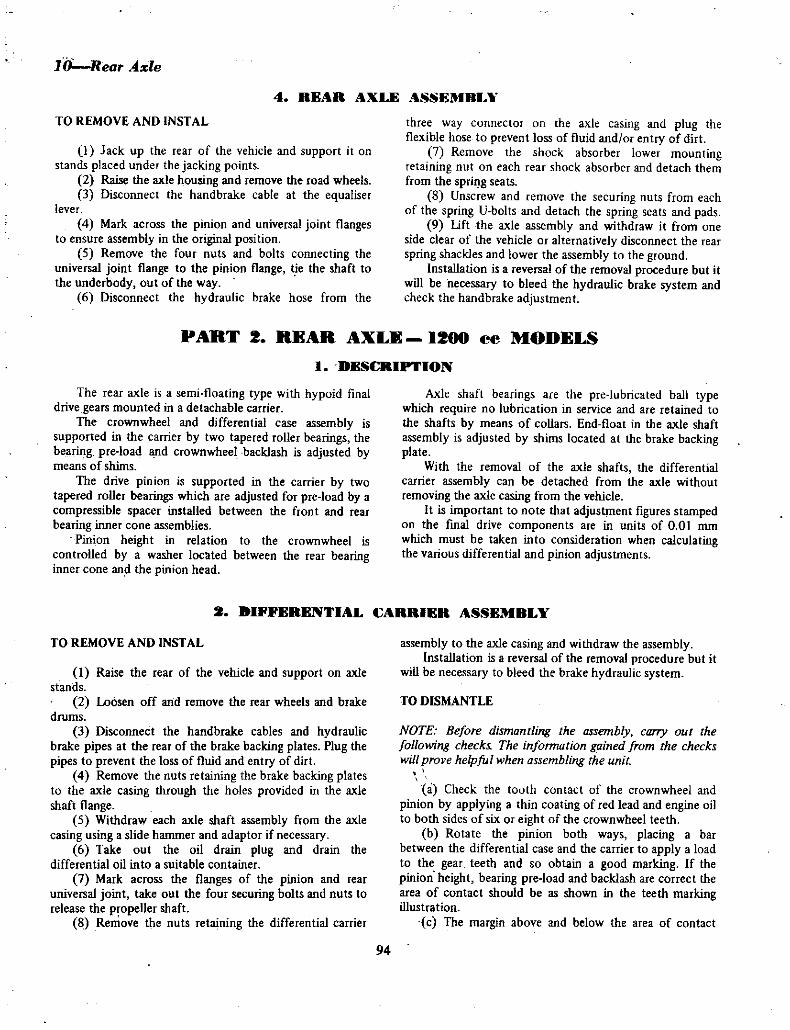
10Rear Ade
TO REMOVE AND INSTAL
4 REAR AXLE ASSEMRL1f
ll Jack up the rear of the vehicle and support it on
stands placed under the jacking points2 Raise the axle housing and remove the road wheels3 Disconnect the handbrake cable at the equaliser
lever
4 Mark across the pinion and universal joint flangesto ensure assembly in the original position
5 Remove the four nuts and bolts connecting theuniversal joint flange to the pinion flange tie the shaft to
the underbody out of the way6 Disconnect the hydraulic brake hose from the
three way connector on the axle casing and plug theflexible hose to prevent loss of fluid and or entry of dirt
7 Remove the shock absorber lower mauntingretaining nut on each rear shock absorber and detach themfrom the sprillg seats
8 Unscrew and remove the securing nuts from eachof the spring V bolts and detach the spring seats and pads
9 tift the axle assembly and withdraw it from one
side clear of the vehicle or alternatively disconnect the rear
spring shackles and lower the assembly to the groundInstallation is a reversal of the removal procedure but it
will be necessary to bleed the hydraulic brake system andcheck the handbrake adjustment
PART 2 BEAR AXLE 1200 ee MODELS
I DESCRIPIION
The rear axle is a semi floating type with hypoid finaldrive gears mounted in a detachable carrier
The crownwheel and differential case assembly is
supported in the carrier by two tapered roller bearings the
bearing pre load and crownwheel backlash is adjusted bymeans of shims
The drive pinion is supported in the carrier by two
tapered roller bearings which are adjusted for pre load by a
compressible spacer installed between the front and rear
bearing inner cone assembliesPinion height in relation to the crownwheel is
controlled by a washer loc ted between the rear bearinginner cone and the pinion head
Axle shaft bearings are the pre lubricated ball typewhich require no lubrication in service and are retained to
the shafts by means of collars End float in the axle shaft
assembly is adjusted by shims located at the brake backingplate
With the removal of the axle shafts the differentialcarrier assembly can be detached from the axle withoutremoving the axle casing from the vehicle
It is important to note that adjustment figures stampedon the final drive components are in units of 0 01 mm
which must be taken into consideration when calculatingthe various differential and pinion adjustments
TO REMOVE AND INSTAL
2 IFFER l I AL ARRIER ASSEMBLY
1 Raise the rear of the vehicle and support on axle
stands2 Loosen off and remove the rear wheels and brake
drums
3 Disconnect the handbrake cables and hydraulicbrake pipes at the rear of the brake backing plates Plug the
pipes to prevent the loss of fluid and entry of dirt4 Remove the nuts retaining the brake backing plates
to the axle casing tIuough the holes provided in the axleshaft flange
5 Withdraw each axle shaft assembly from the axle
casing using a slide hammer and adaptor ifnecessary6 Take out the oil drain plug and drain the
differential oil into a suitable container
7 Mark across the flanges of the pinion and rear
universal joint take out the four securing bolts and nuts to
release the propeller shaft8 Remove the nuts retaining the differential carrier
assembly to the axle casing and withdraw the assemblyInstallation is a reversal of the removal procedure but it
will be necessary to bleed the brake hydraulic system
TO DISMANTLE
NOTE Before dismantling the assembly carry out the
following check The information gained from the checks
will prove helpful when assembling the unit
a Check the tooth contact of the crownwheel and
pinion by applying a thin coating of red lead and engine oilto both sides of six or eight of the crownwheel teeth
b Rotate the pinion both ways placing a barbetween the differential case and the carrier to apply a load
to the gear teeth and so obtain a good marking If thepinion height bearing pre load andbacklash are correct thearea of contact should be as shown in the teeth markingillustration
c The margin above and below the area of contact
94

BEARING CA
rCONE
CAPBOLTS 1ra
SPACER
i ot9t I I
ORIVE PINION BEARINGCOMPRESSIBLE SPACER
BEARING
FLANGE
NrBEARING CAP 0 I
SHER
Gm I IOUTER CONE OilSeAL
CAP BOLTS
should be the same and the contact margin should run
approximately three quarters of tpe tooth length check the
patterns on both sides of the toothd Mount a dial indicator gauge on to th differential
carrier housing so that the plunger is in contact with and at
right angles to the heel of a crownwheel tooth then zero
the dial gaugee Hold the pinion firmly and rock the crownwheel
back and forth t check the backlash on the dial gaugeCheck the backlash at approximately three positionsaround the crownwheel Backlash is correct when withinthe limits of 0 10 IS mm 0 004 0 006 in
NOTE Having completed the foregoing checks dismantle
the assembly as follows
1 Take out the carrier bearing cap bolts and detach
the caps Check that the caps are marked in relation io the
carrier tq ensure installation in their original position2 Lift out the differential assembly from the carriei
but nsure that the pearing outer cones are kept with thei
respective bearings
NOTE To facilitate assembly carry out rhe followingcheck
a Using a pre load measuring gauge or spring scaleand cor check the torque required to rotate the pinion at
the flange end Torque required should be within the limits
of 4 5 kg cm 3 5 c 43 in lb Not the reading3 With the pinion flange held to prevent it from
turning remove the flange retaining nut and vasher
CROWNWHEEL BOLTS
tt
LOCK PLATE
DIFFERENTIAL CASE
AND BEARINGS
CROWNWHEEL
OOTER CONE O
Exploded View of Differential Final Drive Components
R ar Ax ell
4 Using a suitable puller withdraw the pinion flangefrom the end of ihe pinion shaft
5 Using a soft metal drift tap the pinion shaft with
rear bearing inner cone anq rollers and bearing spacer out ofthe differential carrier housing
6 Working through tpr rear bearing outer cup drift
out the front bearing i ner cqne and rollers and the pinionflange oil seal
NOTE Unless replacement of the pinion taper bearings is
intended do not remove the taper bearing outer cones fromthe carrier
Provided replacele t of the pinionis not required do
not remove the rear bearing inner cone assemblv rom t e
pinionIf however replacement ofone or both of the above is
required continue dismantling as follows
7 Using a suitable puller or a press remove the rear
taper bearing inner cone assembly and adjusting washerfrom the pinion
8 Draw or press the taper bearing outer cones fromthe arrier
NOTE Before dismlUltIing the differeniial check thJ carrierbearings at each end of the differimtiatcase Provided the
bearings are fit for further service do not remove them
from position
9 Mark the position of the crownwheel in relation tothe differential case
10 Release the locks from the crownwheel itainingbolts and remove the bolts and crownwheel
II Knock out the differential shaft lock pin from the
crownwh el side of the differential case
12 Knock out the differential shaft and remove the
pinions and side gea s togetlier with the thru t washers
NOTE It is important that each pinion and side gear
together with its thrust washer is marked in relation to the
differential case to ensure original installation on assembly
9S

T UST ER 0P
THRUST HE
0 DIFFERENTIAL SHAFT OR
io
THRUSTE
12 Rear 4 le
Exploded View of Differential Case Components
SIDE GEAR
THRUST WASHER
I
13 If necessary for bearing replacement or bearingpre load or backlash setting use a suitable puller and drawthe carrier bearings from each side of the differential case
Note the adjusting shims between the bearings and case
TO CLEAN AND INSPECT
I Wash all components in a cleaning solvent andblow dry with compressed air
2 Check the crownwheel and pinion for wear pittingor damage
NOTE Crownwheel and pinion are supplied as matchedsets only therefore damage to one item requires thereplacement ofboth
3 Check the differential carrier bearings for wear
pitting or damage Ifa bearing is faulty renew the cOflpletebearing comprising inner cone rollers and outer cup
4 Check the pinion taper bearings and renew as
described in 3
5 Examine the differential pinion and side gear teethand thrust faces for wear pitting or damage Check that thethmst washers are in a serviceable condition
6 Check the differential shaft for wear pitting or
damage Replace parts listed in 5 and 6 if not in
serviceable condition
CARRIER
li
DIFFERENTIAL
LOCK PIN
CARRIER BEARING
7 Examine the differential case for damage and or
distortion and renew if necessary Check alsn the pinionand side gear thrust faces in the case for wear and or
pitting8 Ensure that all shims and spacers are free of
dam ge
TO ASSEMBLE AND ADJUST DRIVE PINION
Where the old pinion and bearings are serviceable andthe tooth contact turning torque and backlash checksmade on dismantling are satisfactory then assembly is a
reversal of the dismantling procedureIf any of the above factors proved incorrect on the
check it will be necessary to carry out the appropriateadjustment as described in this section
This is not the case however when a new piniqn andcrownwheel is to be installed and or the bearings renewed
Adjustment of the pinion position and bearing pre loadthen becomes essential
There are two methods of obtaining the correct pinionposition which is regulated by the washer located betweenthe xear bearing inner cup and pinion head One methodr tlires the use of an arbor and gauge kit to calcuiate the
Exploded View of Drive Pinion Components
BEARINGOUTER CO ES O EAl
ttDRIVE PINION JJIl 1 iO I
COMPRESSIBLE SPACERB RING FLANGE
j96

Rear 41e13
Crown wheel and Pinion Mating Numbers and Pinion Head Variation from Stand rd Figure Units of 0 01 m
thickness of washer requ rcd The secund method entails
the alteration of the existing washer thickness to
compensate for the new pinion head variation using the old
pinion head variation as a guideNote that the pinion head variation from standard
figure is given in units of 0 0 mm
To Adjust Pinion Position
Method I With special tools
1 Instal the front and rear bearing outer cones to the
carrier2 Instal the rear bearing inner cone assembly and
original adjusting washer to the dummy pinion3 Fit the dummy pinion to the carrier and instal the
fron t taper bearing and the pinion flange
NOTH Do not instal the bearing pre load spacer at this
point
4 Instal and tighten the flange retaining nut until the
correct initial turning torque of the pinion is ohtained see
specifications This should be checked with a pre load
measuring gauge or spring scale and cord5 Mount the arbor into the differential case carrier
bearing bores so that the gauge rod is directly over the
pinion head6 Using feeler gauges check the clearance between
the pinion head and the tip of the gauge rod and note the
measurement
7 Calculate the thickness of washer required to
obtain correct pinion position from the followingequation
W N H xO OI 0 2 T in mm
Definition
W thickness of adjusting washer fittedN clearance figure obtained in 6 with feeler gaugesH pinion head variation figure on the pinion head
T thickness of washer reR uired to correctly positionpinion
ExampleW 2 95 mm
N O4mm
H I
Therefore
2 95 04 I x 0 01 0 2 3 16 mm
Thickness of washer required to orrectly positiqnpinion is 3 16 mm 0 1244 in
8 Remove the dummy pinion assembly from the
carrier and withdraw the rear bearing inner cone and old
adjusting washer from the dummy pinion9 Instal the washer as calculated to the pinion and
refit the rear bearjng inner cone
NOTE Ensure that the chamfer on the adjusting washer is
towards the pinioll head
Tu Adjust Pinion Position
Method 2 Without special tools
In the event of the arbor and gauge kit not beingavailable it will be necessary to use the washer removed
from behind the rear bearing inner cone plus or minus as
the case may be the figure etched on the new pinion as a
starting point for pinion position adjustment This methodof adjustment entails assembling the pinion and adjustingpinion bearing pre load fitting crown wheel and differentia
assembly and adjusting the backlash and taking teeth
97

14Rear Axle
markings with red lead or engineers blue This is a trial and
error method until a satisfactory marking is obtainedIf a new crown wheel and pinion are to be fitted with
the old pinion bearing it is a relatively simple matter to
calculate the thickness of the pinion positioning washer ifthe washer from the old pinion is kept intact and used
again taking into consideration the markings on the oldand new pinions
Example I
If both pinion markings are 0 or zero the originalwasher will be correct
If the old pinion marking is 0 or zero and the new
pinion marking is 2 then 0 02 mm must beSUBTRACTED from the original washer thickness
Again if the oe pinion mark is 2 then 0 02 mm
must be ADDED to the original washer thickness to givethe correct pinion position
Example 2Where the old pinion marking is 2 and the new pinion
marking is 2 the position is slightly more complicatedAs 0 02 mm was added to the washer thickness fur a
zero marked piflion to compensate for the 2 mark on theold pjnion head the 0 02 mm must now be subtracted fromthe present washer thickness and a further 0 02 mm
subtracted for the 2 marking on the new pinion headThus 0 04 mm should be subtracted from the washerthickness when replacing an old pinion marked 2 with a
new pinion marked t2
The pinion head thickness as calculated in the previousparagrap is an accurate starting point for pinion positionadjustment but final assessment will be influenced by the
crownwheel tooth contact markings taken after thecrownwheel to pinion backlash has been made
TO ADJUST PINION BEARING PRE LOAD
I With the selected pinion positioning washer fittedetween the rear bearing inner cone and pinion head instal
a ncloY bearing spacer to the pinion
NOTE Ensure that the chamfer on the adjusting washer isawards the pinion head
2 Instal a new oil seal in the carrier and insert the
pinion assembly into the carrier and through the front taperbearing and oil seal
NOTE Lubricate the oil seal lips and bearings bur ensure
that the pinion thread nut and washer are free of oil or
grease
3 Fit the plOlOn flange washer and retaining nut
during the tightening of the retaining nut rotate the pinionto seat the beariitgs
NOTE Tighten the retaining nuta little at a time checkingthe bearing pre load frequently to avoid exceeding the
specified beanzg pre uad and rewillillg Ill wrque fsee
specifications for permissable limits on bearing pre load andnut rorque
Do not slacken back the flange retaining nut if the
speCified bearing pre load is exceeded il is essenlia ill thiscase In renew the compressible bearing spacer
4 Recheck the pinion positiun to ensure Ihat therehas been no alteration in height
TO ASSEMBLE AND ADJUST DIFFERENTIAL
1 Instal the side gears and pinions together with
mating thrust washers into their former positions in thedifferential case
2 Instal the differential shaft aligning the hole in heshaft with the hole in the case for the lock pin
3 Check the clearance by feeler gauge between theside gears and thrust washers Clearance should be withinthe limits of 010 0 20 mm 0 004 0 008 in If
necessary replace the thrust washers to obtain the correct
clearance4 Instal the differential shaft lock pin from the right
side of the case and secure in position by peening the hole5 Position the crownwheel on the differential case
according to the marks made on dismantling6 Instal the crownwheel retaining bolts with new
lock plates Tighten the bolts progressively a little at a timein a diagonal pattern to the specified torque Secure thebolts by turning the lock plate tabs against the bolt heads
IDENTIFICATION LETTER AND VARIATION FIGURE
Carrier Bearing Housing Variation from Standard FiguresUnits of 1 01 mm
98

IDENTIFICATION LETTER AND
Differential Case Variation from Standard Figures Units of
0 01 mml
NOTE During the tightening procedure lightly tap each
bolt head to assist seating of the crownwheel on the case
7 Provided the original differential case and carrier
bearing assemblies are to be used mount the differentialcase assembly with the original pre load shims between the
carrier bearing inner cones and case into the carrier
8 Instal the carrier bearing caps and bolts accordingto the mating marks on the cap and housing Tighten the
retaining bolts to the specified torque
NOTE Operations 7 and 8 are only practical when the
dismantling check on tooth contact pattern backlash and
pre load proved satisfactoryHowever if the differential case or carrier bearings
have been replaced or the differential checks provedunsatisfactory it will be necessary to adjust the differentialas follows
9 Using a surface plate and dial indicator measure the
variation from standard width standard width 17 5 mm
0 689 in of each carrier bearing when subject to a 2 5 kg5 5Ib load Variation should be in units of 0 01 mm
10 Calculate the thickness of shims required for each
carrier bearing by the following equationsLeft side Tl A C D E x 0 01 0 2
Rear 4de15
Right side T2 B D F x 0 01 0 2
Definition location of letters and variation fromstandard figures in units of 0 01 mm
A left side carrier bearing housingB right side carrier bearing housingC D differentill case
E F bearing width variation from standard for eachcarrier bearing in units of 0 01 mm
Thickness of shims required for each carrier bearingcalcolated by the equation will be in hundredths of a
millimetre 0 01 mm
NOTE If the old carrier bearings are to be taken back into
sel1Jice the preload required will be slightly less than that
for new bearing To compensate for the old bearings reducethe overall shim thickness alreadv calculated by 0 030 07 mm 0 001 0 003 in
II Instal the selected shims on their respective endsof the differential case and fit the carrier bearing inner coneassemblies
12 With the carrier bearing outer cones mated with
the correct inner cone assembly instal the differential in
the carrier using a soft faced hammer to tap the assemblyin to he bearing seats
13 Instal the carrier bearing caps and bolts accordingto the mating marks on the cap and housing Tighten the
retaining bolts to the specified torque
14 Check the crownwheel backlash as previouslydescribed in TO DISMANTLE If necessary adjust the
backlash by transferring the appropriate thickness of carrier
bearing shims from one side to the other according to the
requirement15 Check the crownwheel runout if the run out
exceeds specifications remove the differential assemblydetach the crownwheel from the case and check the contact
faces of the case and crownwheel for dirt or burrs Duringassembly ensure that the crownwheel is pulled down
squarely to the case If the run out still exceeds
specifications a new crownwheel and pinion set will have to
be installed
16 Carry out the tooth contact pattern check as
described previously in TO DISMANTLE Provided pinionheight backlash and pre loads are correct the desired tooth
patterns will be obtained
17 Instal the assembly in the vehicle in the reverse
order of removal fill with correct quantity and grade of oil
PINION on SEtI
3 Mark the relative position of the pinion llange and
propeller shaft flange if not previously marked and remove
the retaining bolts support the propeller shaft to the
underbody clear of the pinion flange
I DRIVE
TO RENEW OIL SEAL AND OR PINION FLANGE
I Raise the rear of the vehicle and support on stands
under the axle housing or raise the complete vehicle on a
hoist
2 Remove both axle shaft and bearing assembliesfrom the axle housing as described under AXLE SHAFT
AND BEARING TO REMOVE
NOTE As the tension of the lip ofa newpinion oil seal on
the seal surface of the pinion flange will be greater than
that of the original component particuiarly ifa new flange
99

16Rear Arle
is alsv being instaled it will be lleceSJf ru cukulate theoverall preload to ensure that after reassemb v the actual
pinioll bearing pre load is the same as originally Thiscalculation is ca ied out dun ng the following op rations
4 Using a suitable pre load measuring gauge measure
the overall tOlque required torotat the drive pinion at theflange before loosening the flange securing nut and make a
record of the I1gure obtained5 Undo the pinion flange retaining nut
approximately three complete turns and using a suitablepoller draw the flange along the pinion shaft to abut the
retaining nut
6 Tighten the flange retaining nut until there is a
slight end float in the pinion shaft bearings
NOTE This will relieve the assemb y ofallY pillioll bearillgpreload but will maintain the side bearing preJoad and the
turque lleceJsaf IV fum lhe piniull assemblJ against the
retardillg effect of the old oil seal
7 Again using a pre Iuad measuring gauge measurethe torque required to rotate the pinion at the flange endwith negative pinion bearing p e Ioad as in operation 4and record the ligure obtained
8 Undo and completely remove the pinion flangeretaining nut and washer and again using a suitable pullerwithdraw the flange from the pinion shaft
9 Prise the defective seal assembly out of thedifferential carrier bore and discard
10 Clean the recess for the new seal in the end of thecarrier bore and the splines on the end of the pinion shafe
NOTE Ensure that 110 foreign matter finds its way infO the
front pinion bearing or a false pre load setting will beobtained
II Apply a light coating of suitable sealingcompound to the outer surface of a new pinion oil seal
position it in the bore of the differential carrier so that the
lip of the seal faces the pinion bearing and tap it fully into
place
NOTE The new seal should be allowed to stand immersedin light engine oil for at least one hour before installing
12 Apply a coating of non hardening sealingcompound to the inner splines of the pinion flangeposition the flange on the end of the pinion shaft and titthe washer and a new nut on the threaded end of the pinionshaft
NOTE Renew the pinioll jlallge if the splilles dre a loose fit
UIl he slwJi or iJ the seal surJ n of the jlange is grovl ed ur
rough A new jlange should be a reasonably right fit on the
shaft splines
11 Hold the tlange against rotation and carefullytighten the pinion retaining nut until there is just a slightend float in the pinion shaft and bearings
14 Using a pre load measuring gauge measure the
torque required at the flange end to rotate the pinion with
negative pinion bearing pre load but with the originalpre load on the carrier side bearings plus the retardingeffect of the new pinion seal and if fitted the new pinionflange Record the figure obtained
15 Subtract the figure obtained in operation 7from that obtained in operation 14 and add the result to
the tlgure obtained in operation 4
16 The result calculated in operation 15 will be
the overall pre load required at the pinion flange when theassembly is correctly adjusted
17 To apply the overall pre load see operations 15and 16hold the pinion flange against rotation and verycarefully lighten the flange retaining nut to just remove the
bearing end float Rotate the assembly to correctly seat the
pinion bearings18 Continue to tighten the flange retaining nut
carefully a fraction of a turn at a time alternativelychecking the overall pre load at the pinion tlange until the
pre load gauge reading is as detailed in operation 16
NOTE It is most important to adhere strictly to the
instructions given in operation i8 to avoid exceeding thecalculated overall preload bv tightening the retaining nut
beyond this point and over compressing the special spacerbetween the inner cones of the pinion bearings In the event
of the pinion bearing preload figure being exceeded byovertightening the flange nUl it will be necessary to remOle
the pinion flange and oil seal again and withdraw the frontpinion bearing inner cone instal a new collapsible spacerand re instal the bearing cont oil seal pinion flange withwasher ilnd a new nut and carry out operations 17 and
IS again
19 When the calculated pre load has been correctlyapplied to the assembly connect the rear universal jointflange to the pinion flange then instal and tighten the boltsand self locking nuts
20 Instal both rear axle shaft and bearing assembliesin the axle housing and fit the brake drums and road wheels
Adjust the brake shoes
21 Check the lubricant level in the rear axle and topup with the correct grade ifnecessary
22 Check the differential housing breather to make
sure it is clear23 Lower the vehicle to the floor
100

Rear Axle17
4 AXI S U T AXD n AIIIl4
TO REMOVE
1 Raise the rear of the vehicle and support on stands2 Loosen off and remove the rear wheel and brake
drum
NOTE It may be necessary to release the brake adjusterseveral notches if the brake drum proves difficult to
remove
3 Disconnect the handbrake cable and hydraulicbrake pipe at the rear of the brake backing plate Plug the
pipe to prevent the loss of fluid or entry of dirt
4 Remove the nuts retaining the brake backing plateto the axle casing through the holes provided in the axle
shaft flange5 Withdraw the axle shaft from the axle casing using
a slide hammer and adaptor if necessary
NOTE Keep intact the end float adjustment shims fittedbetween the backing plate and casing
TO RENEW AXLE SHAFT BEARING
I Remove the axle shaft as described above2 Place the axle shaft so that the bearing retaining
collar is resting on an anvil and using a hammer and cold
chisel make a cut in the top of the retaining collar
NOTE Use care not to damage the axle shaft with the
chisel if it is necessary to cut completely through the colar
Usually it will be necessary to make shallow cu ts only in
order to expand the collar sufficlentlv for it to be removed
3 Using a press and press plates support the bearingon the inner race and press the axle shaft out of the
bearing or use special tool No ST37130000 to pull the
bearing from the shaft4 Detach the bearing spacer brake backing plate and
grease trap
5 Clean all parts and check the condition of the axle
shaft for wear damage or distortion
6 If necessary remove the old oil seal from the axle
casing grease the seal lips of e new seal and instal into the
casing7 Position the grease trap brake backing plate
bearing spacer and bearing on the axle shaft
8 Press a new bearing retaining collar onto the shaft
to secure the bearing a load of 4 5 tons will be necessaryfor collar installation
TO INSTAL
1 Pack the axle shaft bearing with suitable grease and
smear the ou er face of the retaining collar with grease2 Position the shims originally removed on the brake
backing plate3 Insert the axle shaft assembly into the rear axle
casing engaging the splines of the shaft and differential side
gear
NOTE Ensure that the oiLseal lip is not damaged as the
shaft is passed through it
4 Instal and tighten the retaining nuts to secure the
assembly to the axle casing flange5 Mount a dial gauge to the brake backing plate with
the gauge plunger bearing on the axle shaft flange and zero
the gauge Check the end float on the axle shaft which
should be within the limits of 0 0 1 mm O 0 004 in
6 If adjustment to the shaft end float is necessaryadd to or subtract from the shims located between the
brake backing plate and axle casing until the correct
end float is obtained
7 Connect the brake cable and hydraulic brake pipeandrefit the brake drum
8 Adjust the braking system and bleed as describedin the BRAKES section
9 Ensure that the rear axle oil level is correct refitthe road wheel and lower the vehicle to the ground
TO REMOVE AND INSTAL
5 ll AH XI SS flU
1 Jack up the rear of the vehicle and support it on
stands placed under the jacking points2 Raise the axle housing and remove the road wheels3 Disconnect the handbrake cable at the equaliser
lever
4 Mark across the pinion and universal joint flangesto ensure assembly in the original position
5 Remove the four nuts and bolts connecting the
universal joint flange to the pinion flange tie the shaft to
the underbody out of the way6 Disconnect the hydraulic brake hose from the
three way connector on the axle casing and plug the
flexible hose to prevent loss of fluid and or entry of dirt
7 Remove the shock absorber lower mountingretaining nut on each rear shock absorber and detach them
from the spring seats
8 Unscrew and remove the securing nuts from each
of the spring U bolts and detach the spring seats and pads9 Lift the axle assembly and withdraw it from one
side clear of the vehicle or alternatively disconnect the rear
spring shackles and lower the assembly to the groundInstallation is a reversal of the removal procedure but it
will be necessary to bleed the hydraulic brake system and
check the handbrake adjustment
101

18Rear Ale
f IlEAR XI I FAUIT IUAf NOSIS
1 Rear wheel noise
Possible cause Remedv
a Wheel loose on axle flange Check condition of axle and wheel and tighten or
renew componentRenew faulty components
b Defective brake components shoes or wheelcylinder
e Worn or defective axle shaft bearing lack oflubrication
d Bent axle tube or shaft
e Wheel out of balance or bent
Renew faulty components
Renew axle housing and or shaft
Check and rectify wheel balitnce or renew or true up
2 Final drive gear noise
Possible cause Remedy
a Faulty inion bearingsb Faulty differential carrier bearingsc Lack oflubrication
Renew pinion bearings and readjust gearsRenew carrier bearings and readjust gearsCheck condition of assembly flushand renew
lubricantCheck condition of gears and readjust or renewas
mated pairCheck condition ofassembly adjust bearing pre loador renew faulty componentsOverhaul assembly and renew faulty componentsOverhaul assembly and renew faulty componentsFaulty final drive gears and adjustment Renew andreadjustRenew housing and faulty components
dl Incorrectly adjusted crownwheel and pininn
e Incorrectly adjusted bearing pre load pinion or
carrier bearingsf Excessive noise orgrind under load
g Excessive noise or grind on overdrive
h Excessive noise on coast
i Bent axle housing
3 Excessive backlash in differential
Possible cause Remedy
a
b
c
d
e
Looseness between axle shaft and differentialside gear splinesWorn dtfferential side gear thrust washersWorn differential pinion thrust washersExcessive backlash between differential side gearsand pinionsExcessive wear between differential shaft andpinions and or shaft bore in carrier housing
Check and renewaxle and or side gears
Check and renew differential side gear thrust washersCheck and renew differential pinion thrust washersCheck condition of gear and pinion teeth and renew
gear and or pi ion thrust washersCheck and renew faulty components
4 Repeated axle shaft breakage
Possible cause Remedy
a Bent axle housingb RepeatJd over loadingc Abnormal clutch operationd Incorrectly torqued axle shaft bearing
retaining plate nuts
Check and renew housingRevise load capacityRevise driving habits or check condition of clutch
Tighten axle shaft bearing retaining nuts to specifiedtightening torque
102

STEERINGS E FIC TlONS
Type Recirculatingball nut ardworm
15 0 1Ratio
Preload adjustmentSteering worm shaftSector shaft end tltrust
Steel shimsSteel sh and
screw
Shim thickness
Five sizes for worm shaft 0 05 0 20 mm
0 0020 008 in
1515 1655mm
0 0590 065 in
0 05 0 10 mm
0 0020 004 in
0 05 mm
o ooi in
Four sizes for sector shaft
Collapsible steering columnbush
Sector shaft end playStee ing wheel turning torqueminus sectQr shaft 5 0 kg cm
69 injoz
Ball nut balls
Number
Size new
385 556 mm
0 218 in
0 23 litre0405 Imp pts0486 USpts
SAE 90 EP
Oil capacity
Oil grade
TORgUE WRENCH SEITINGS
Column flange fixing bolts 2 8 kg m
20 ftjlb5 0 kg m
36 ft lb
14 0 kg m
101 ft lb63 kg m
45 ft lb2 6 kg m
I9 ft lb2 6 kg in19 ft lb35 kg m
25 ft lb
Ball stud nut
Sect9f shaft to pitman arm nut
Idler arm nut
Gear housing fixing bolls
Idler arm fixing bolts
Steering wheel lock nut
I DESRIPTION
The steering gear is the worm and re circulati g ball
typeThe steering shaft at the worm end operates in two ball
thrust bearin and at the steering wheel end in a plasticbush
The sector shaft operates in bronze bushes and has an
oil seal at its lqwer end
A three toothed sector on the upper end of the sector
shaft engage a sector on the side of the ball nut
There are 60 steel balls in the ball nut 5 556 mm
0 218 in in dial1eter
The steqing worm shaft bearing adjustment is
controlled by shims between the steering box and the
s eering column flangeSector shaft end thrust is controlled by an adjusting
screw and lock nut in the top cover d attached to a
recessed slot in the upper end of the sector shaftThe steering gear li kage omprises a steeriI1g
connecting rod connected by a ball join at oe end to the
steering gear pitman arm and at the other end to the idler
arm which in turn pivots on a bracket attached to the
underbody frameAn adjustable tie rod on either side of the steering
linkage is attached by ball joints at its inner end to the
connecting ro and at its outeeend to the steering arm
attached to the brake backing plate These tie rods are a
means for setting the alignment for the front wheels
toe in and must both be the same length to maintain the
steering box on centre whefl the front wheels are in
straight ahead position
TO REMOVE Column Gear Change
l STEERING GEAR ASSEMIILY
1 Disconnect the lead at the positive terminal of the
battery2 Unscrew the two horn ring emblem retaining
screws and lift off the horn ring3 Remove the steering wheel retaining nut and
withdraw the steering wheel
4 Remove the column shell retaining bolts and shell
oosen the trafficator clamp screws disc nnect e
electrical plug arid slide the trafficator switch off the
steering column complete with the column shell cover
5 Remove the two bolts connecting the steeringcolumn to the facia
6 Remove the dust cover screws conne tjng thC cover
to the floor
103

2Steering
7 Release the car shift control rod drclip at the
support bracket at the lOp of the control rod
t 8 Remove the E dip and pin retaining the gear
change lever to the control rod and detach the lever and
bush9 Working at the steering hox end of the linkage
disconnect the gear change rods from the control levers byremoving the split pin and nat washer on each of the rod
trunnions
10 Take out the lower support bracket retainer bolt
and detach the control rod lever retainer
II Place all linkages to one side and secure
I2 pemove the lower change speed lever and bush bysliding off the lower end of the contrbl rod
13 Poll down on the control rod and remove the
control lever actuating pin14 Press down on the control rod insert and
disengage from the bracket on the upper end of the steeringcolumn Withdraw the insert bush and spring frqm the end
of the control rod
15 Withdraw the control rod from the drivers
compartment of the vehicle
16 Disconnect the steering linkage connecting rod at
the steeri g gear pitman armball joint17 Remove the three retaining bolts securing the
steering box to the body18 Withdraw the steering box from the engine
compartment
TO DISMANTLE
l With the steering box removed from the vehicle as
already described remove the fjller plug turn the box
upside down and draiIl off the oil2 Remove tf1e pitman ann retaining nut and spring
washer Using a suitable puller remove the pitman arm
NOTE Prior to removal ensure that the pitman ann is
marked in relation to the sector shaj This willfaci itate
assemMv
3 Loosen the sector shaft adjusting bolt lock nut and
back Off the adjusting bolt4 To remove the sector shaft from the hoosing
remove the four retaining bolts attaching the cover to the
housing and remove the cover and sector shaft Unscrew the
adjusting bolt out of the cover and lock nut and slide the
adjusiing bolt and shim out of the upper end of the sector
shaft5 Take o t the four retaining bolts securing the
steering column tube flange to the housing Withdraw the
column assembly Do not allow the ball nut to rotate on
the worm as damage will be incurred to the ball guides
NOTE The cover plate shim are situated with a gasket o
the cover plate Ensure tho the shims are not dahlagedduring dismantling procedure Store shims and gasket in a
safe place for reassembly
6 Remove the worm shaft frum the column tubto
7 Remove the upper bearing outer cup from the
olumn tube tlange with a suitable puller8 Remove the lower bearing outer cup from the
steering box with a suitable puller9 Remove the sector shaft oil seal from the steering
box10 Before dismantling ball nut and worm shaft
check for correct alignment and excessive wear
I Remove the clamp fitted to the ball guide tubes
and withdraw the ball guide tube from the ball nut Emptythe b ls into a suitable container
2 Invert the nut and rotate the column left to rightuntil all 38 Qalls have been removed from the nut Havingremoved the balls the nut can be withdrawn from the
column
TO CLEAN AND INSPECT
I Wash all components in cleaning solvent and dryoff
2 Check the steering worm shaft bearing inner cones
for wear or pitting3 Cpeck the outer cups and balls of the steering
worm shaft bearings for wear and pitting4 Check the ball nut and track guides and balls for
wear or pitting5 Chec the ball tracks on the steering worm for
wear and pitting6 Check the sector shaft pushes for wear and
alignment7 Check the ball nut sector teeth for wear and
chipping8 Check the adjusting bolt head and shim for
wear or damage9 Replace all worn or faulty components as found
necessary
TO ASSEMBLE
I Fit the ball nut to the worm with the ball guideholes uppermost
2 Place 19 balls in each of the two holes on the same
side Qf the nut As the balls are being fitted turn the worm
shaft gradually away from the holes until the 38 balls are
installed
NOTE If the balls are Slopped bv the end of the wonn use
a clean punch or rod to hold down the balls previous v
jitted and tum the shaft in the opposite direction until the
passage is clear
Add remainder of the balls filling the circuit fully3 Instal the remaining 22 balls in the guide tubes
11 to each lube Hold the guides together and plug with
petroleum jelly ready for installation4 Fit the guide tubes to the guide holes of the ball
nut
1

Exploded View of Steering Gear Components 1200 Model Shown
Typical also of 1000 Models Except for Collapsible Column
5 Fit the ball guide retaining clamp to the ball nut
and secure with two screws
6 When replacing the sector shaft bushes in the
steering box press the new bushes into position so that the
plain end of the bush is flush with the oil seal shoulder in
the bore housing7 Pross the oil seal into the housing Ensure that the
oil seal is lightly lubricated with a suitable grease8 Fit the bearing cups to the column tube and
steering box Fit the worm shaft and bill nutassembly into
the steering box with the ball nut sector facing the sector
shaft side of the box Fit the column tube over the worm
shaft and attach to the steering box with new gasket and
shims as removed Instal the foor bolts and adjust the
worm shaft bearing pre load by adding or removing shims
See Specifications9 To determine the correct end clearance and lash
adjustment on the sector shaft fit the lash adjuster bolt to
the slot and check the clearance with a feeler gaugeClearance should be 0 01 0 03 mm 0 0004 0 0012 in
Shim sizes are available in different thicknesses see
Specifications for the purpose of obtaining the correct
end tloatI U Rotate the worm shaft by hand ontil the ball nut
is located in the centre posit ion to allow the centre tooth of
the sector shaft to engage the centre tooth of the ball nut
Prior to installing the sector shaft smear the shaft with oil
nsert the sector shaft and cover into place and checkthat back lash exists between ball nut and sector shaftteeth before tightening the side cover bolts
I I Temporarily secure the adjusting screw with the
lock nut
Steering3
TS
LotNUT
I
Check Sector Shaft End Float
105

4Seeeriiag
12 Rotate the sector shaft several times ensuring it
turns smoothly13 Fit the pitman arm to the sector shaft and ensure
that the marking on the pitman arm is in line with the
marking on the sectorshaft14 Select the central point in the steering box
release the adjusting SCrew lock nut and adjust the screw
until the mOVement of the pitman arm is within 0 01 rnm
10 0039 in
15 Refill the steering box with SAE 90 EP oil andinstal the plug
16 Instal the steering box assembly 10 the vehicleInstallation is a reversal of the removal procedure
I7 Finally check the steering wheel aligitment gearshift mechanism and lubricate all applicable points
DESCRIPTION
1 COLLAPSIBLI ST fliiX6
The principle of the steering column is to compress on
impact of a pre determined forceThe operation of a collapsible steering column
assembly is the same as that of the conveniional type The
only variance is that caution must be exercised when
working on the column when in situ Severe bumping or
downward pressure to or on the steering wheel could resultin the shearing of the nylon pins connecting the upper andlower shafts causing the column to collapse
UPPER COLUMN SHAFT
I
rSNAP RING GROOVE LOWER COLUMN TUBE
1LOCK COllAR BOm
b
The column assembly is comprised of an upper andlower shaft lower column tube jac et tube column bushand collar steering post clamp snap link and washer
The column is so designed so that on impact the forceapplied to the steering wheel forces the upper shaft downshearing the nylon pinS connecting the upper and lowershaft allowing the upper shaft to move down over the
lower shaftThe jacket is constructed of a fibre glass material and is
of the convoluted design This design allows the jacket toabsorb initial shock then collapse when the upper shaft isforced down over the lower shaft
PLASTIC PINS LOWER COLUMN SHAFT BALL NUT
I I
BEARING
tCOLUMN BUSH
tCOLLAPSIBLE COLUMN TUBE ASSYOLT
A BOLTS
F ISLIDING BLOCK COLUMN CLAMP
COLUMN FLANGE SHIMS STEERING BOX ASSY
Exploded View of Collap ible Steering Column
Components fitted to 1200 Models
TO REMOVE AND INSPECT
4 JAKET TUDf
I Remove the steering gear assembly in the same
manner as the conventional assembly but firstly removethe snap ring from the upper face of the column bush Donot bump the steering wheel or convoluted section of theassembly during removal
2 Carry out an inspection of the steering box and
componen ts in the normal manner
3 With the steering jacket iristalled on the shaftmeaSUre the end clearance between the jacket bush flange
and the washer on the shaft If the end clearance is not
within 3 mm 0 118 in the jacket can be put back intoservice by means of a thicker thrust washer at the top ofthe jacket
4 Inspect the plastic pins conoecting the columnshafts for fatigue
5 Inspect the steering column lock collar for fatigueand looseness
6 Support the column shaft on two V blocks at theworm end and check the shaft for distortion If distortionexceeds 1 0 mm 0 039 in at the steering wheel endcorrect or replace as necessary
i06

1 With the previous adjustments completed and the
ball nut fitted to the worm shaft lubricate where necessary
and fit the worm shaft and column to the steering box
Tigh ten the four bol ts connecting the column to the
steering box and check the adjustment2 Fit the upper bush to the column and apply the
washer and snap ring Check the snap ring for correct
seating in the groove3 Raise the bush until the top of the bush contacts
the lower surface of the washer Back off the bush until a
clearance of less than 1 0 mm 0 039 in is obtained
Check for free turning of the column sh ft and adjustthe bush accordingly Shoold the clearance between the
washer and the bush be insufficient binding will result4 Align the upper end of the jacket lube with the
groove in the cohmn bush and chalk twq symmetricalpositions on the jacket
Caulk the two posi tions to a depth not exceeding 4 0
mm 0 157 in and ensure that the inner periphery of the
tube measurement is less than 318 mm 1 252 in
Re check the clearance of the bush and should the
clearance be incorrect it will be necessary to fe caulk or
adjust by adding shims
5 Fit and adjust the sector shaft and tighten the side
cover bolts to the specified torque
Upper End of Steering Worm Shaft and Column Tube
CIRCUe
0
COLUMN TUBE
S eering 5
TO ASSEMBLE AND INSTAL
TO INSPECT AND INSTAL
a 4OLUMl LAMP
I Inspect the two aluminium spacer blocks for
damage with particular attention to the nylon pins
2 Check the colomn clamp for damage and cracking
3 Check that the bolts connecting the clamp to the
jacket lock collar are of the correct length Fit the clamp to
the jack lock collar ensuring that the bolts do not contact
the steering shaft
4 Fit the steering assembly to the vehicle with the
open end of the spacer blocks facing the steering wheel It
is imperative that the spacer blocks be fitted in this manner
to ensure that on impact the nylon pins yill shear off
allowing the column to move forward away from the driver
Replace parts where necessary
6 STIlIlHIl4 II KA41l
3 Using a suitable extractor press the tapered ball
joint out of the tapered hole in each steering ann
4 Repeat operations 1 and 2 to detach the inner
end of each tie rod from the steering connecting rod and
withdraw the tie rods from the vehicle
TO REMOVE AND DISMANTLE
I Jack up the front of the vehicle block the rear
wheels and lower the vehicle on to jack stands
2 Take out the split pin and remove the castellated
nut securing the tie rod outer ball joint to the steering arm
on each suspension unit
IDLER ARM ASS
TIE ROD BALL JOINT
TIE ROD BALL JOINT PITMAN ARM BALL JOINT
ITIE ROD
fIfl CONNECTING ROD
TI
TIE ROD BAll JOI IDLER ARM BALLJOINT
View of Steering linkage Components Removed from Vehicle 1000 Models
107

6Steering
5 Take out the split pin and remuve the nut un thesteering connecting rod joint bolt on the pitman arm
6 Using a suitable extractor press the bolt out of the
forward end of the pitman arm
7 Using similar procedure as in operations 4 anddisconnect the steering connecting rod from the
forward end of the idler arm and withdraw the connectingrod from the vehicle
8 If tie rods ends are unserviceable they must be
replaced as a complete unit not serviced separately
TO ASSEMBLE AND INSTAL
I If the steering connecting rod ends are to berenewed press the new bolt and bush into the rod until theend of the outer sleeve of bush is flush with the end of the
SPLIT PIN
BALLKl lTr NU
SPLIT PIN
@NUT
T1EIROO 7TIE ROD BAllJOIHT
7
eye in the uIlnccting rod Repeat JIl the uther end of therod
2 Position the connecting rod on the pitman arm andidler arm Fit castellated nuts and split pins
3 Attach the inner ball join t of each tie rod to the
connecting rod tighten the castellated nut and secure witha new split pin
4 Attach the outer ball joint of each tie rod to its
respective steering arm tighten the castellated nut and fit a
new split pin5 Measure the length of tie rods between the ball
stud centres Distance between Centres should be 296 8 mm
1169 in
6 Centre the steering box with the wheels in thestraight ahead position and check the wheel alignmenttoe in as described under LINKAGE ADJUSTMENT
CONNECTING ROD
l
SPLrTPIN
NU AlL JOINT
T1E ooNUTo
IE ROD BALL JOINT
SPLIT PIN
Dismantled View of Steering Linkage Components 1000 Models
IOU AIUI
TO REMOVE AND DISMANTLE
1 Remove the split pin and castellated nut securingthe idler arm to the connecting rod and detach theconnecting rod
2 Remove the two nuts and bolts securing the idlerbracket assembly to the body side member and remove theassembly from the vehicle
3 Remove the split pin and castellated nut and pressthe idler arm pivot bolt out of the bracket body
TO ASSEMBLE AND INSTAL
I With the idler assembly removed check the bushesfor wear and fatigue
If new bushes arc required wet the bushes with a soapy
solution and instal them in the idler housing Ensure thatthe lip of the bushes is protruding equally at either end
The wetting procedure is unnecessary where a nylonbush is fitted
2 Instal the idler arm pivot bolt fit the castellatednut and tighten to the specified torque See Specificationsection Fit a new split pin
3 Position the bracket assembly on the body sidemember and secure with the two retaining bolts and nuts
4 Connect the steering connecting rod to the idlerarm and instal the castellated nut and new split pin
5 When the idler arm assembly is mounted on the
body the centre line of the idler arm should be parallel to
the chassis6 Check and if necessary adjust the front wheel
alignment toe in as described in LINKAGEADJUSTMENT
TO ADJUST STEERING LOCK STOPS
II UKAf F o UST IF TS
1 Set the vehicle up with turn tables under the frontwheels and slacken the lock nuts and stop adjusting bolts
2 Turn the front wheels to the left lock and checkhe degree angle of the wheel Adjust the stop bolt setting
the angle to the specified degree reading and tighten thelock nut See Specifications
3 Turn the front wheels to the right hand lock and
check the degree angle of the wheel Adjust the stop boltsetting the angle to the specified degree reading and tightenthe k nut See Specifications section
4 Recheck both locks and remove the turn tables
108

FLAT WASHE
G NUT
e
Steerirrg 7
o NUT
FLAT WASHER
lASTrC BlAH
iiiLASTIC BUSH
fi
o ORING
Exploded View af Idler Arm Campanents 1200 Madels
Exploded View af Idler Arm Campanenn 1000 Madels
TO CHECK AND ADJUST TOE IN
I With the vehicle on a level floor jack up the front
of the vehicle2 Spin each wheel in turn and using a piece of chalk
mark a line around the periphery of each tyre as near to the
centre as possible3 Lower the vehicle to the floor bouncc the front
and rear of the vehicle up and down several times and let it
find its own height Set the front wheels in the straightahead position
4 Mark the centre chalk line on both tyres at a
position approximately 203 254 mm 8 10 in above
the floor and in front of the suspension5 Using a suitable telescopic gauge measure the
distance between the two marks on the tyre een tees and
record the measurements6 Maintain the wheels in the straight ahead position
roll the vehicle lurwanJ until the marks are the same
distance above the floor at the rear of the front suspension7 Again use the telescopic gauge to measure and
record the distance between the maries on the tyresThe distance measured at the front of the wheels ust
be approximately 5t1 mm 0 2t0 04 in Sedan and 6t1
mm 0 24t0 04 in Station Wagon less than the
measurement taken at the rear of the wheels
8 If adjustment of the toe in is required loosen the
lock nuts on each tie rod and turn each rod by eq al
aITounts until the toe in is Correct Tighten the four lock
nuts
NOTE II is importall t to make equal adjustmen ts on each
tie rod to maintain the central pusition ufthe steering gear
If all oplical or other tvpe gauge is used follow the
manufacturers instmctions
109

BSteering
ft ST ER t FAUIT D t OS S
Excessive play or looseness in steering gear
Possible cause
a Steering gear worn or out of adjustment
b Steering linkage ball joints worn or loosec Pitman arm loose on sector shaftd Idler lever bush and bolt worn
e Steering gear loose on sub frame mounting bolts
2 Heavy steeringPossible cause
a Low or uneven tyre pressuresb Steering gear incorrectly adjustedc Lack of lubricant in steering linkage joints
d Front suspension worn or out of alignment
e Mis alignment between steering gear and columnmountings
t Soft or sagging front springs
3 Steering pulls to one side
Possible cause
a Uneven tyre wear or pressure
b Incorrect front end adjustmentc Dragging brakesd Broken or sagging rear spring so
e Broken rear spring mounting bolts
I Damaged front suspension or front sub frame membersg Faultv or damaged front crossmember
4 Front wheel wobble or shimmyPossible causes
a Looseness in steering gearb Uneven tyre wear or incorrect tyre pressures
c Tyre and or wheel unbalanced Front end damaged or out ofalignmente Worn or badly adjusted front wheel bearingI Wheel alignment incorrectly adjustedg Loose or worn tie rod endsh Faulty shock absorbers
S Steering erratic or wanderingPossible cause
a Incorrect or uneven camber andjorc3stor settingb Smooth front lyresc Excessive play in steering gear and or linkaged Excessively high or low tyre pressurese Loose or incorrectly adjusted front wheel bearings
Remedv
Overhaul steering gear renew faultycomponents and adjustTighten or renew faulty componentsTighten pitman ann retainingnutRenew and adjust idler lever bush and boltTighten mounting bolts and check alignmentof steering gear mounting
Remedy
Chech tyres and inflate to recommended pressuresCheck and readjust steering gearAscertain cause of loss ofllbricant and lubricatesteering linkage where applicableCheck front end for wear renewworn componentsand fe align front end
Check and align steering gear and olumn mountings
Renew springs and check front end alignment
Remedy
Check conditions of tyres and inflateto recommended pressuresCheck front end alignmentCheck and adjust brake shoesRenew faulty springsRenew faulty componen tsCheck and renewdamaged componentsCheck and renew front crossmember
Remedv
Rectify and adjustCheck condition of tyres and inflateto recommended pressuresCheck and balance as necessaryCheck and rectify front end damage and alignmentCheck condition and adjust wheel bearingsCheck and adjust front wheel toe in alignmentCheck and renew faulty componentsCheck and renew as a pair
Remedv
Check and renew components to rectifyCheck and renew tyres as necessaryCheck and renew faulty components readjustCheck and inflate to recommended pressuresCheck and adjust front wheel bearings
llU

FRONT SUSPENSIONpAnT I 1000 SERIES
SPEFI T 4 NS
Type Transverse leaf
spring with upperand lower controlarms tubularshock absorbel1
and radius rods
Spring dimensions
Length 976 mm
36 925 in
50mm
1 968 in
4mm
0 157 in
6
120mm4 724 in
Width
Thickness
Number of leavesFree camber
Wheel alignmentToe in 2 3mm
0 0787
0 118 in
20 15 min
I 15 min
60 30 min
450360 36 min
Caster angleCamber angleKing pin inclinationToe out on turn inner wheel
Toe out on turn Quter wheel
TORQUE WRENCH SEITINGS
Lower ball nut 7 6 kg m
55Ib ft
5 3 kg m
38Ib ftLower control arm connecting bolt
I SPRING AND LOWER ONTIlOIRM
TO REMOVE AND INSPECT
I Jack up the front of the vehicle block the rear
wheels and support the vehicle on jack stands
2 Remove the road wheels3 Remove the two bolts attaching the shockabsorber
to the radius rod and lower control ann
4 Remove the bolts attaching the radius rod to the
lower control arm
5 Sopport the lower control arm with a floor jackand remove the split pin and castellated nut and loweringthe floor jack to withdraw the lower ball joint from thestub axle swivel
6 Working at the opposite end of the control arm
unscrew the nut remove the washers and withdraw the
Radius rod front 4 5 kg m
32lb ft
53 kg m
38Ib ft4 9 kg m
35lb ft53 kg m
38Ib ft2 5 kg in
i8lb fi2 8 kg m
20Ib ft2 2 kg m
16lb ft2 8 kg m
20Ib ft
Radius rod rear
Upper ball joint
Retaining Ilut fulcrum
Stub axle nut
Shock absorber bolt front
Upper ball to control arm bolts
Lower ball to control arm bolts
8RETAINING RING
0DUST SEi
SPRING SUppORTNOT
W@ LOCK WASHER BALL JOINT BOLTS
@ WsHER ttLOWER CONTROL AFM
1
SPACER
BAll JOINTVOTOO T
WASHER v
NUTtt
f 1f
NUTS
Exploded View of Lower Control Arm with Stub Axle and
Swivel Arm Components 1000 Models
111
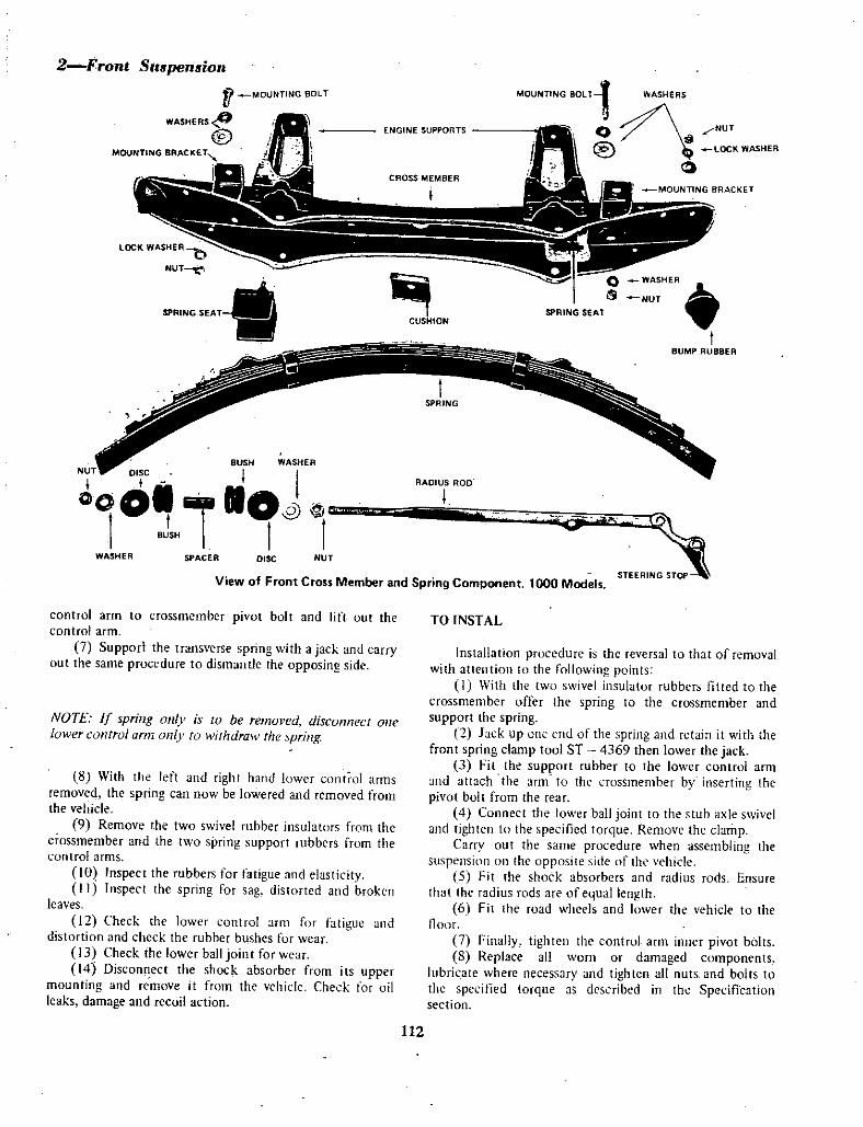
2 Front Suspension
ft MOUNTING BOLT
WASHERS
@ENGINE SUPPORTS
MOUNTING 80LT1 WASHERS
@o
NUT
lOCK WASHER
CROSS MEMBER
I MOUNTING BRACKET
CUSHIONSPRING SEAT
WASHER
NUT
tBUMP RUBBER
BUSH WASHERNUT DISC I It RADIUS ROD
CAOll 10I
1 8JSH I0
I1
WASHER SPACER DISC NUT
View of Front Cross Member and Spring Component 1000 Models
control arm to crossmembcr pivot bolt and lift out thecontrol arm
7 Supporl the transverse spring with a jack and carryout the same procedure to dismantle the opposing side
NOTE If spring Oll V is to be removed discoIJnect onelower control arm Oil lu withdraw the spring
8 With the left and right hand lower control arms
removed the spring can now be lowered and removed fromthe vehicle
9 Remove the two swivel rubber insulators from thecrossmember and the two spring support rubbers from thecornrol arms
10 Inspect the rubbers for fatigue and elasticityII i Inspect the spring for sag distorted and broken
leaves12 Check the lower 10l1tl01 arm for fatigue and
distortion and check the rubber bushes fur wear
13 Check the lower ball join t for wear
14 Disconnect the shock absorber from its uppermounting and remove it from the vehicle Check for oilleaks damage and recoil action
TO INSTAL
Installation procedure is the reversal to that of removalwith attention to the following points
I With the two swivel insulator rubbers fitted to thecrossmember offer the spring to the crossmember andsupport the spring
2 Jack up one end of the spring and retain it with thefront spring clamp tool ST 4369 then lower the jack
3 fit the support rubber to the lower control arm
llld attach the arm to the crossmember by inserting thepivot bolt from the rear
4 Cunnect the lower ball joint to the stub axle swiveland tighten to the specified torque Remove the clamp
Carry uut the same procedure when assembling the
suspension on he upposite ide of thL vehicle5 Fit the shock absorbers and radius rods Ensure
that the radius rods are ofequal length6 Fit the road wheels and lower the vehicle to the
Ilum7 Finally tighten thc control arm inner pivot bolts8 Replace all worn or damaged components
lubricate where necessary and tighten all nuts and bolts to
the specified torque as described in the Specificationsection
112

Front SlIspension3
U L NT
BACKING PLATE
RADIUS ROD
LOWER BALL JOINT
Rear View of the Left Hand Side Suspension arid Steering Componelts 1000 Models
TO REMOVE AND INSPECT
2 UPPER 4 ONTROJ AIlM
0 Raise the front of the vehicle block the rear
wheels and support the vehicle on jack stands2 Remove the road wheels3 Withdraw the split pin unscrew the castellated nut
and disconnect the arm from the stub axle swivel at the
upper ball joint4 Working at the opposite end of the control arm
remove the two retaining nuts and bolts and lift off thecontrol arm assembly noting the position and number of
shims between the pivot shaft and the body frame5 Clean the arm assembly and inspect for fatigue or
distortion6 Inspect the bushes for wear If replacement is
necessary press t e bushes out from the opposite ends andremove the pivot shaft To fit new bushes place the pivotshaft in the upper control arm and press the bushes homeensuring that the splines on the bush are correctly alignedwi th the splines in the control arm
7 Inspect rebound rubbers for fatigue and cracking8 Check the upper ball joint for wear
9 Replace all worn or damaged components where
necessary
View of Upper Inner Control Arm in Mounted Position1000 Model
113

4Ifront SU5pe 8ion
UPPER CONTROL ARM
WASHER
OCK WSHER
NUT
Dismantled View of Upper Control Arm Components 1000 Models
TO INSTAL
rnstallation procedure is tne reverse to that of removal
with attention to the following pointsII As a starting point fit the camber adjusting shims
NUT
LOCI WASHER
WASHER
BOSH
fULCRUM SHAfT
CAMBER ADJUSTING SHIMS
00
V
eiin the positions from which they were removed
2 Check and adjust front end alignment3 Carry out tightening torque to required
specifications See Specification section
4 Lubricate all points where necessary
TO REMOVE AND INSPECT
3 STUB AXLE SWn EL
1 Raise the vehicle block the Tear wheels and
support the vehicle on jack stands2 Remove the road wheels3 Remove the hydraulic brake line retaining clamp
disconnect the brake line and plug the line to avoid loss offluid and ingress of dirt
4 Remove the brake drum and hub assembly as
described in the 1200 Series FRONT SUSPENSIONsection in this manual
5 Disconnect the stub axle swivel from the upper and
lower control arms and withdraw the assembly from the
vehicle
6 Check the swivel and stub axle for distortion
7 Remove and inspect the wheel bearings cups andseals and assembly as described in the 1200 Series
TO INSTAL
Installation is the reversal of the removal procedurewith attention to the following points
I Bleed the hydraulic system and top op the master
cylinder2 Carry out tightening procedure as specified in the
Specification section
4 TO REK AND AD1UST ASTOR ND CAMBER ANGUlS
I Check and adjust tyre pressures and set the vehicle
up with the alignment equipment being used according to
tJle manufacturer s instructions Bounce the vehicle up anddown and let it find its own level
2 Check the castor angle and if necessary adjust bytransferring shims from one upper suspension pivot shaft
mounting bolt to the other Transferring shims from the
rear bolt to the front bolt will decrease castor and
transferring shims from the front bolt to the rear bolt willincrease castor
3 Check the camber angle and adjust by removing or
installing an equal number of shims at each of the two
upper suspension pivot shaft mounting bolts
114

Front Suapenawn5
TO REMOVE AND INSTAL
5 SHOK ABSORBERS
I Raise the front of the vehicle and support on
stands2 Remove the two bolts connecting the shock
absorber to the lower control arm and radius rod
3 Remove the nut and washer connecting the upperend of the shock absorber to the sub frame and withdraw
the shock absorber from the vehicleInstallation is a rever al of the removal procedureCheck test and bleed the shock absorber as described
under TO TEST AND BLEED
TO TEST AND BLEED
The extent to which a shock absorber can be tested
without special testing equipment is limited to the
following
1 Mount the shock absorber upright in a vice by the
lower eye or stem
2 Grasp the upper half of the shock absorber pull up
to the fully extended position and then slowly push down
until the shock absorber is fully compressed3 Repeat operation 2 six or eight times to remove
any slack spots caused by air in the system If slack spotsexist and cannot be removed by this method the shock
absorber is evidently defective and should be renewed
NOTE The resistance will be greater on upward stroke ofthe shock absorber than on the downward stroke
4 Check the body of the shock absorber for dents or
damage and for fluid leakage The shock absorbers cannot
be repaired in service and should be renewed if defective
TO REMOVE AND INSTAL
8 BALL JOINTS
I Raise the front of the vehicle support on stands
and remove the road wheel
NOTE It will also be necessarv to support the lower
control arm on a jack to relieve the springpressure on the
upper rebound rubber
2 To remove the upper and lower bali jointsseparately remove the split pin and nut from the upper ball
joint and using a suitable spreader press the ball jointtapered spindle oot of the stub axle swivel
NOTE Use care not to damage the hydraulic brake pipeby stretching
3 Remove the bolts connecting the ball joint to the
upper control arm and withdraw the ball joint4 Sopport the lower control arm with a jack and
remove the split pin and nut from the lower balljointUsing a suitable spreader press the lower ball joint
tapered spindle out of the stub axle swivel5 Remove the bolts connecting the lower ball joint
to the lower control arm and withdraw the balljoint6 Place the ball joint in the vice and check the dust
cover metal circlip or 0 ring whichever is fitted to the
dust cap for damage or fatigueInstallation is a rev rsal of the removal procedure
1 Front end noise
7 FRONT SUSPESIOX AIJLT DIAt NOSIS 1000 SERIES
Possible cause
a Loose upper suspension mountingb Loose or worn suspension unit lower
ball jointc Noise in shock absorber unit
d Worn steering linkage or idler arm
componentse Mal adjusted front hub bearings
Remedy
Tighten mountingTighten or renew lower ball joint
Renew shock absorber unit
Renew defective components
Readjust or renew hub bearings
Continued next page
115

6Front Suspension2 Poor or erratic road holding ability
Possible cause
a Low or uneven tyre pressureb Defective shock absorber operationc Incorrect front end alignmentd Loose or defective front crossmembere Weak or broken front spring leaf or leaves
I Broken leaf in or weak rear springg Loose or defective front hub bearingsh Mal adjusted or defective steering gear
or idler
i Defective tyres or front wheel balance
j Worn or sagging spring pivot rubber
3 Heavy steering
Possible cause
a Low or uneven tyre pressure
b Incorrect front end aligrunentc Lack of lubricant in steering gear
and componentsd Worn or damaged front suspension
e Sagging or broken transverse springI Incorrect adjustment ofsteering gear
4 Front wbeeI w bble or shimmy
Possible cause
a Tyre and or wheel unbalanceb Rapid and uneven tyre wear
c Worn or loose hob bearingsd Worn or damaged steering linkagee Incorrect front end alignment
I Mal adjusted or worn steering gear
g Steering gear loose on frame mountingor offcentre
5 Vehicle pulls to one side
Possible cause
a Low or uneven tyre pressure
b Incorrect or unequal front end alignmentside to side
c High road camber
d Weak or broken rear springe Front brake draggingf Steering gear off centre
Remedy
Inflate tyres to recommended pressuresCheck and renew faulty onit
Check and adjust alignment as necessaryCheck and tighten or renew memberCheck and renew springCheck and renew leaf or complete rear springAdjust or renewhub bearingsAdjust or renew faulty components
Renew defective tyres and balancefront wheels
Renew spring pivot rubbers
Remedy
Check and inflate tyres to recommended
pressuresCheck and adjust aLignmentCheck oil level in steering gear and applygrease gun to any grease nipplesCheck and renew worn or damaged componentsand adjust front end alignmentRenew springCheck and adjust steering gear
Remedy
Check and balance tyre and wheel as a uni t
Check front end alignment see Wheels and
TyresCheck and renew or adjust hub bearingsCheck renew faolty components and adjustAdjust and or renew suspension componentsto restore alignmentRenew and oradjust steering gear componentsCheck and tighten mounting and or centre
steering gear
Remedv
Check and inflate tyres to recommended
pressuresCheck and adjust to restore correct
alignmentAvoid as far as possibleRenew faulty springAdjust or rectify cause
Check and re centre steering
116

Type
Coil springFree length
Loaded length
Load at loaded length
Total number of coils
Wire diameter
Wheel alignmentCaster angle Sedan models
aster an le Station wagonCamber angle
King pin inclinationSedan modelsStation wagon
Toe out on turnsInner wheelOuter wheel
Toe in
Sedan models
Station wagon
Front Suspension 7
PART II 1200 SERIESSPEIFICiTIONS
Suspension and TORQUE WRENCH SEITINGSshock absorberunit with coil Gland packing I 10 kg m
spring and lower 79Ib ft
control arm Piston rod nut 6 5 kg m
47lb ft
Upper mounting bolts 2 1 kg m
338 tlO mm IS Ib ft
133 t 04 in Stabiliser bar link
203 tS mm retaining nuts 12kg m
7 99t0 2 in 8Ib ft
200 kg Stabiliser bar bracket bolts 12 kg m
44llb 8Ib ft
77 Stub xle nut 2 4 kg m
IOmm 17lb ft
0394 in Radius rod to frame 6 5 kg m
47Ib ft
Radius rod to control ann 3 0 kg m
1010 t3021Ib ft
1040 t30 Lower ball joint to strut 6 1 kg m
1005 t 3044 lb ft
Lower ball joint retaining nut 7 4 kg m
53 Ib ft
7055Engine mounting bracket nut 12 kg m
8 Ib ft7045 t30 Disc brake caliper bolts 6 1 kg m
44 lb ftDisc to hub assembly 6 0 kg m
430 t1 43Ibfft360t O Backing plate installation
bolts 3 7 kgfm261b ft
5 lmm Lower ball joint to
2 t 04 in control arm 3 0 kg m
6tlmm 21Ib ft
24 t04 in Back off to nearest castellation
I DESRIPTION
Each McPherson strut type front suspension unit
comprises a vertical tubular shOCk absorber surrounded at
the upper end by a coil on top of which is the upper springmounting attached to the underside of the front wheel
housingThe piston rod of the shock absorber is in turn
attached to the upper centre of the spring upper mountingby a rubber mounted thrust bearing assembly
The suspension unit foot integral with the wheel stub
axle is attached to the lower end of the shock absorber
tubeA ball joint incorporating the steering arm is attached
to the suspension unit foot by two bolts and springwashers
The ball bolt of the ball joint attaches the suspensionunit to the suspension control arm which pivots at its inner
end on a bolt and rubber bush attaching it to the
suspension crossmemberA radius rod is attached at its rear end by tW9 bolts to
the outer end of the lower control arm and at its forward
end to a bracket on the under frame by a rubber bush
mountingarrangementA stabiliser bar attached to the body sub frame
forward of the suspension and connected between the outer
117

BFronl Srupenaion
end of each suspension unit control arm by a rubber bushed
link
Caster camber and swivel inclination are set in
production and cannot be adjusted Any variations in these
angles will be caused by wornor damaged components
i
If the coil spring is to be removed from the unit special
clips must be used to hold the spring in a compressedcondition to assist in the removal and installation of the
unit
2 WBEELBlJB AND BEARING
TO REMOVE AND DISMANTLE Drum Type Brakes
I Place blocks at rear and front of rear wheels raise
the front of the vehicle and support on jack stands2 Remove the wheel nuts then take off wheel and
drum3 Remove the dust cover withdraw the split pin and
remove huh retlillill nut and washer4 Remove the outer bearing cone and withdraw hub
assembly from the stub axle
5 Place the assembly in a vice and using a drift or
suitable hand tool tap out the grease seal
6 Lift out the inner bearing cone re mount hub
assembly in a vice and using a suitable drift tap out both
inner and outer bearing cups from the hub assembly
TO CLEIN AND INSPECT
I Wash the bearings cups and hub assembly in a
suitable cleaning solvent and carry out a thoroughinspection of component parts
2 Inspect bearing cups and cones for scoring and
chipping Should it be necessary to renew either a bearingor cup they must be renewed as a complete unit Do not
mix new and used parts3 Once having removed the grease seals they shauld
be replaced with new seals4 Check the stub axle for miSalignmen t and the
inner bearing seating area for scoring5 Check the castellated nut and the thread on the
stub axle for damage or wear If the thread on the stub axle
is badly damaged the suspension unit must be replaced
TO ASSEMBLE AND INSTAL
I Drift the two hub bearing cups into position in the
hub ensuring that their tapers are opposed to each other
2 Pack the space in the hub between the cups with
BEARING
SEALB A NG CUP 1
I0 ot
BACKING PLATE AND BRAKE ASSY
wheel bearing grease apply grease to the rollers of the inner
cone and place it in position in the hub3 Place a new grease retaining seal on the inner end
of the hub and tap into position4 Apply wheel bearing grease to the inner cone and
rollers of the outer hub bearing place the hub asselflbly on
the stub axle and fit the roller bearing to the hub5 Fit the D washer and castellated nut on the stub
axle and while rotating the hub tighten the nut until a
slight preload is placed on the hub bearings6 Slacken off the nut until there is a slight end float
in the hub bearings and then tighten with the fingers until
the end float is just removed7 Fit a new split pin and replace the grease retaining
cap
NOTE If the split pin hole does nor line up with a slot in
the nut release the nutuntil pin can be installed
8 Instal the road wheels and re adjust the brake
shoes Lower the vehicle to the floor
TO REMOVE Disc Type Brakes
1 Place blocks at front and rearof rear wheels
2 Raise the front of the vehicle and support with
jack stands3 Screw off the wheel retaining nots and lift off the
road wheel4 Disconnect the hydraulic brake hose adjacen t to
the chassis from the brake pipe and plug the pipe to
avoid leakage of hydraulic fluid
5 Remove the retaining bolts securing the caliper to
the stub axle flange and withdraw the caliper assembly6 Remove the dust cover arid split pin unscrew the
nut from the stub axle7 Withdraw the hub and disc assembly from the stub
axle8 Remove the washer and outer bearing cone from
the hubHUB
BEARING CUP KEYED WASHER
1 B A NGNUT
CAP
0dWSPUT PI
Exploded View of Front Hub Assembly with Backing Plate Assembly Drum Brakes
118

9 Place the assembly in a vice and using a drift or
suitable hand tool tap out the grease seal
10 tift out the inrier bearing cone re mount the
assembly in the vice and using a suitable drift iap out both
inner and outer bearing cups from the hub assembly
I I Remove the bolts connecting the disc to the hub
assembly and separate the disc from the assembly
TO CLEAN AND iNSPECT
I Wash the bearings cups hub assembly in cleaningsolvents Inspect bearings and cups for scoring chips and
pitting if damaged replace as complete asseinblyInspect the disc for distortion chipping or cracking
Replace where necessary When replacing the disc also
renew the bolts2 Renew the grease seal
Front SUspension 9
3 Check the stub axle for misalignment and the inner
bearing seating area for scoring4 Check the castellated nut and the lhread on the
stub axle for damage or wear If the thread is badlydamaged the suspension unit must be replaced
TO ASSEMBLE AND INSTAL
I Assembly and installation procedure is the reversal
to that of removal See also Drum Type Brakes
2 When reassembling the bearings to the hub packthe bearings and hub with heavy duty wheel bearing greaseto manufacturer s instructions
3 Tighten and adjust to specified torque see
Specification sectiori4 Bleed the hydraulic system and t st the brakes
I STABILlSER BAR
TO REMOVE
I Chock the rear wheels raise the front of the
vehicle fit the special spring clips and support on jackstands Remove the road wheels
2 Remove the engine splash cover
3 Remove the retaining nuts rubber bUshes and
washers attaching the stabiliser bar link to the lower
suspension arms
4 Take out the retaining bolts attaching ihe stabiliser
supporting brackets to the chassis and withdraw the
stabiliser bar from the vehicle5 Inspect the bar for distortion and fatigue Renew
all rubber bushes if necessary
TO INSTAL
NOTE Instal the stabiliser bar with the paintediden tification mark to rhe left hand side of the vehicle
1 Place a flat washer and rubber half bush on each ofihe stabiliser bar links so that the flange of the halfbush is
I
adja ent to the washer2 With the sweep of the stabilisingbar facing
upwards position the bar with its link ends in the
suspension urn holes Instal each half bush and washer onthe erids of the bar link and fit the self locking nuts
3 nstai the mounting bracket s on the siabiliser bar
mounting bushes and secure with bolts and lock wash rs
4 Tighten the nuts on the ends of the stabiiiser bar
link to the specified torque see Specification section
NOTE Ensure the vehicle is in the lowered position when
final tightening procedure is carried out
5 Instal the engirie splash cover
6 Lower the front of the vehicle and remove the
spring clips
4 RADIUS RODTO REMOVE
1 Remove the retaining bolts attaching the radius rod
to the lower support arm
2 Remove the retaining nui washer and rubber
bushes from the forward end of the radius rod and
RADIUS R D
CUP WASH
Nfln
STOP WASHER RUB8ER BUSH
withdraw the Hjd from the bracket on th under frameCheck the radius rod for distortion and fatigue Renew
all nibber bushes and washers if necessary
Replace the radius rod where necessary
CUP WASHER
r
lrnRUBBER BUSH FLAT WASHER
Radius Rod Forward Mounting 1200 Model
119

lOFront Suspension
TO INSTAL
Installation procedure is the reversal of removal withattention to the fqllowing points
1 Tighten the nuts and bolts to the specified torque
set Specific3tion sec ion and ensure that the rods are
fitted correctly2 The rods are marked LH and R H and must be
fitted accordingly3 Ensure that the metal bush and rubber bushings are
seated correctly
TO REMOVE
a SUSPENSION UNIT
I Block the rear wheels Raise the vehicle wi th a jackunder the suspension control arm on the side that is to beremoved and rerilOve the road wheel
2 Wijh the full weight of the vehicle still on the coilspring fit the special spring clips to maintain the coil springin the compressed position
3 Raise ilie front of the vehicle and support withjack stands
4 Remove the hub grease retaining cap withdraw the
split pin and remove the stub axle nut and washer5 Withdraw the brake drum and hut assembly from
the stub axle Remove the outer wheel bearing
NOTE Where disc brakes are jilted use the procedilre forremoval of hub disc and calipaDisconnect the brake hosemid plug the hydraulic line
6 Uriscrew the four retaining nuts and bolts securingthe bacIdng plate to ihe stub i le flange
7 Now remove Jhe hydraulic br e Iin retainingc lip
Orin Side Suspension Unit 1200 Models
from the suspension unit Withdraw the backing plateassembly from ihe stub axle and support the backing plateto avoid damage to the hydraulic line and hose
8 Withdraw the split pin and unscrew the castellatednut securing the tie rod end ball bolt to the steering arm
Remove the ball bolt from the steering aim9 Disconnect the radius rod and stabiliser bar from
the lower suspension control arm
10 Place a jack under the lower suspension controlann
I I Remove the two bolts securing the suspensioncontrol arm to the suspension unit and ball joint
12 Raise the bonnet and working from the enginecompartment remove the retainjng nuts securing thesuspension unit to the upper support member
13 Lower the jack and remove the suspension unitfrom the vehicle
TO CLEAN AND DISMANTLE
I Prior to dismantling of the suspension unit cleanthoroughly and en iUre that a clean working area is availableprior t6 dismantling
2 Fit the strut attachment tool ST35650000 tn thestrut buter casing and mount in a vice Fit coil springcompressor to the suspension unit and compress the springuntil the insulator can be turned by hand
NOTE To renlOve the lock nut from the piston rod instala nul Il one of the bolts connecting the suspension to the
bodv and llsing as a lever base app v a screw driver to thelock nut Ind using a levering action release the lock nut
3 Remove the suspension mounting insulator thrust
bearing spring se t bumper rubber and dust cover
4 Back off the spring compressor and remove the coil
spring5 Using special gland packing wrench remove the
gland packing
NOTE Prior to removal push the piston rod down to thelowestpoint clean the gland nul and surrounding area
If the gland packing nut has been caulked break theseal and removegland nu t
6 Pull the piston rod slowly upwards remove the 0ring from the tnp of the piston goide and withdraw thepiston rod and cylinder assembly
120

Strut and Coil Spring Assembly 1200 Model
NOTH Do not remove the piston rod and g1ide from the
cylinder as they are serviced as an assembly
TO CLEAN AND INSPECT
I Drain oil from the casing and cylinder wash
components and dry off with ompressed air
Non metalic parts to be cleaned by air only2 New gland packing 0 ring and hydraulic fluid is
to be osed every time the assembly is dismantled3 Check the strut outer casing for distortion and
cracks4 Inspect the spindle for distortion Check the base
and threaded section for fatigue5 Test the coil spring for sag and fatigue and check
rubber components6 Check thrust bearing for pitting scoring and
general wear
TO ASSEMBLE
1 Prior to assembly ensure that all parts are clean
Avoid damage to work ng parts as they are precision ll1adeDo not use cotton waste for wiping down Particles
Front Suspension II
NUT
1
WASHER
ISTON ROD
t8EARING
r
STU
rSTRUT ASSEMBLY
BUMP U88EReStrut and Coil Spring Coponimts 1200 Model
could lodge in the cylinder and result in faulty operation2 To reassemble fit the outer casing to the
t i
suspension unit bo y3 Place the piston rod and cylinder assembly in the
outer casing and fill the casjng with the specified quantityand type of oil
The operating efficiency of the suspension unit is
greatly influenced by the specified quantity and quality of
hydraulic fluid4 Fit the 0 ring to the top of the piston rod guide
and assemble the gland packing Take care not to damagethe oil se l during assembly
se special tool No ST35550000 gland packing guideto instal gland packinfNOTE Prior to tightening the gland packing nut withdraw
the piston rod approximately 90 mm 3 54 in to f cilitate
bleeding of the shock absorber
5 Using special tool ST35500000 tighten the glandpacking nut to the specified torque see Specificationsection
6 Bleed the air from the shock absorber by
121

12 Jlront Suspension
pumping he piston up and down until all au is expelledThis is carried ou t in the foHowing manner Have the
spindl l tI1e down position when the piston is drawn
upwards and the spindle in the upper positian when the
piston is pushed down
Expulsion of all air from the system can be determined
by even pressure in either direction of the piston7 Fully extend the piston rod and fit the coil spring
bump rubber spring seat and dust cover Compress the coil
spring and fit the bearing assembly and mounting insulator
NOTE Ensure that the thrnst bearing gland packing IItIC
anu oil sal are lubricated pnor w assemblY
Fit a new washer and self locking nut and tighten to
the specified torque see Specification section8 Remove the coil spring compressor and fit the
suspension unit to the vehicle Renew all parts where
necessary
TO INSTAL
Using the reverse procedure to that of removal
observing torque settings set out in the specificationsection fit the suspension unit to the vehicle
6 SVSPENSION ONTROI ARM
TO REMOVE
I Block the rear wheels raise the front of the vehicle
and support with jack stands Remove the road wheel
2 Ref1ove the retaining bolts and nuts connectingthe iadi rod and stabiliser bar to the control arm
3 Remove the lower ball joint retaining bolts
4 Unscrew the retaining nuts connecting the control
arm to the body member and withdraw the control arm
from the member
TO INSPECT
1 Clean the conirol arm and inspect the metalic
section for distortion and fatigue Replace if damaged
7 LOWER BALI JOINT
TO REMOVE
I Block the rear wheels raise the vehicle and supporton jack stands Remove the road wheel
2 Remove the bolts and nuts attaching the stabiIiser
bar and radius rod to the lower control arm
3 Take out the retaining bolts attaching the stub axle
assembly and suspension unit to the st ring arrrl4 Withdraw the split pin remove the tie rod ball
2 Check the rubber bushings for damage and or
fatigue Should the rubber bushing require replacing mount
the control arm in the press and remove the bush from the
control arm
To replace the bushing lubricate the bushing with
soapy solution mount the arm in the press and fit the
bushing to the arm
Ensure that the bushing protrudes equally from either
end of the arm collar when fitted
TO INSTAL
Insta11atio procedure is the reverse to that of removal
NOTE Tightening torque for respective nurs andbolts are
contained in the Torque SettingSpecification section
WASHER
UT
BOLTFU8B R BUSHES
Lower Control Arm and Ball Joint
Components 1200 Models
joint retaining nut and disconnect the ball joint from the
steering arm
5 Remove the two bolts connecting the steering arm
to the suspension unit and remove the steering arm
6 Mount the steering arm in a vice remove the splitpin and castellated nut and withdraw the ball bolt from the
arm
122

TO CLEAN AND INSPECT
1 Clean the ball joint in suitable cleaning fluid and
carry out inspection2 Inspect the ball join t for excessive end play and
metal fatigueWhen the end play between the upper spring seat and
top of the spring exceeds 1 0 mm 0 039 in the ball jointshould be replaced
3 Check the shaking torque by mountiog the ball
joint in a vice and attaching a spring gauge to the top of the
ball joint bolt beneath the castellated nut and measure the
amount of torque required to move the ballThe torque reading should be between 35 60 kg em
30 52 Ib in If the readings are not within these
Front Suapenaion 13
tolerances the ball joint should be replacedThe ball joint is not repairable and must be renewed
when found to be defective4 Renew the dust cover ai all times
NOTE To lubricate the ball joint remove the plug at the
base of the ball joint fit a grease nipple and fill with greaseuntil old grease is expelled When lubricating with highpressure gun ensure dust cover is notdamaged
TO INSTAL
Installation is the reverse procedure to that ofremoving
Tightening torque is set out in the Specificationsection
TO REMOVE
8 SUSPENSION ASSEMBLY
I Block the rear wheels raise the vehicle and supporton jack stands Remove the road wheels
2 Disconnect and plug the left and right hand brake
hose then remove the hose retaining spring clips3 Remove the radius rod from the vehicle
4 Disconnect the stabiliser bar from the chassis
5 Using a suitable engine lifting device support the
engine and remove the engine mounting bolts from the
member6 Place a floor jack under the centre of the
crossmember and supporting the meniber remove the bolts
connecting the member to the chassis
7 Remove the self locking nuts connecting the
suspension units to the upper support members8 Lower the floor jack slightly and withdraw the
suspension assembly from the vehicle
TO CLEAN AND INSPECT
I Inspect all insulator rubbers and rubber bushes for
fatigue and wear
2 Check the stabiliser bar and radius rod for
distortion and thread damage
3 Check the suspension crossmember for crackingwith particular attention to the mounting bolt holes
4 Inspect the lower control arm for distortion or
d ge5 Remove the brake drum and hub assembly and
inspect the bearings and stub axle Where disc brakes are
fi tted inspect the disc distortion and fatigue6 Check the coil springs for sag and cracking7 Inspect the strut for distortion and upper support
mounting for cracking8 Check the ball joint operation9 Replace component parts where necessary
TO INSTAL
Installation procedure is the reversal to that of removalwith attention to the following points
1 Instal the stabiliser bar with the paintidentification mark fitted to the left hand side of the
vehicle
2 Instal the radius rods to their respective sides on
the vehicle The rods are marked LH and RH and must befi tted in this manner
3 Lubricate all applicable points4 CarTY out adjustments and torque settings as
annotated in the Specification section
ADJUSTMENT
8 SUSPENSION AND STEERING ANGLES
TO CHECK AND ADJUST TOE IN
I Prior to carrying out a wheel alignment select a
clean and level area to carry out the necessary adjustments2 Carry out a thOtough inspection of the steering
linkage front wheel bearing adjustment suspension jointsand rods springs and suspension unit recoil action Replaceor repair where necessary
3 Inspect the tyres for even tread If found defective
replace with serviceable tyres4 Inflate tyres to correct pressure
I With the vehicle on a level floor jack up the front
of the vehicle2 Spin each front wheel in turn and using a piece of
chalk mark a line around the periphery ofeach tyre as near
to the cen tre as possible3 Lower the front of the vehicle to the floor and
bounce the vehicle up and down several times and let it find
its own level Set the front wheels in the straight ahead
position
123

14Fronl SuapemiOn4 Mark the centre line on both tyres at
approximately 208 254 mm 8 10 in above the floor and
in front of the suspension5 Using a suitable telescopic gauge place it between
the two front tyres on the chalk marks and record the
distance between the centres of the tyres6 Maintaining the wheels in the straight ahead
position roll the vehicle forward until the marks are the
same distance above the floor but to the rear of the
suspension7 Again use the telescnpic gauge to measure and
record the distance between the marks on the tyres The
distance measured at the front of the tyres should be less
than the measurement at the rearof the tyres8 If adjustment is required loosen the lock nut on
each end of each tie rod and turn each rod by equalamounts until the toe in is correct
Tighten the four tie rod lock nuts
NOTE t is important to make equal adjustments on each
tierod to maintain the central position of the steeringgear
f an optical or other type of toein guage is used
follow the manufacturer s instlUcnons
TO CHECK CAMBER AND CASTER
I Before any attempt is made to check the camber or
caster angles or to check and adjust front wheel toe in the
suspension unit should be thoroughly checked to ascertainthat it is in a serviceable condition
The tread of the tyres should be examined for excessive
or uneven wear as certain conditions of tyre wear are
indica tive of damaged or worn componen ts in the
suspension steering linkage and or wheels and bearingsThe vehicle shoold be unladen except for the normal
amount of petrol oil and wateI with the tyres inflated to
the normal pressure2 Check and adjust the tyre pressures and set the
vehicle up with the alignment equipment being used
according to the manufacturers instructions Bounce the
vehicle up and down several times and let it find its own
level3 Check the front wheel alignment toe in and if
necessary adjust as previously described4 Check the caster camber and swivel inclination
according to the instructions set down for alignmen t
equipment being used and compare with the manufacturers
specifications5 If the caster angle is incorrect check the radius rod
brackets and rubber bushes Also check the suspensioncontrol arm rubber pivot bushes for wear
6 If the camber and swivel inclination angles are both
incorrect check the suspension unit upper mounting and
lower ball joint for wear orlooseness Check the suspensioncontrol arm for distortion and its rubber pivot bushes for
wear
7 If the swivel inclination angle is correct and the
camber angle is incorrect the stub axle is bent A new
suspension unit should be installed
8 Measure the toe out on turns of the front wheels
using the equipment according to instructions
If the toein is correctly adjusted and the toe out on
either or both left or right hand turn is incorrect then the
tie rods are Gf unequal length or one or both steering arms
may be bentIn the latter case the steering armis must be renewed
and the steering linkage re adjusted
Note The maximum minimum steering angle toein
toeout on turns is also detennined by the distance
between the face of the adjustable stop fitted to the
steering arm and the bracket on the rear of the lower
control arm when the wheels are turned from lock to lock
When adjusting the steering angle by stop adjusterensure the distance between the radius rod and the tvre is
not less than 30 mm 81 in Should the clearance be
less than specified adjust the angle stop outwards until a
length reading not exceeding 275 mm 11 083 in on the
stop adjuster bolt is obtained
9 For angle and adjustment settings see
Specification section
10 FRONT SUSPENSION FAUI T DIAGNOSIS 1200 SERIES
I Front end noise
Possible cause
a Loose upper suspension mounting or piston rod
bearingb Loose or worn suspension unit lower balljointc Noise in shock absorber unitd Worn steering linkage or idler arm componentse Mal adjusted front hub bearings
Remedy
Tighten mounting andlor adjust piston rod bearing
Adjust tighten or renew lower ball jointRenew shock absorber unit
Renew defective componentsReadjust or renew hub bearings
124

2 Heavy steering
Possible cause
a Low or uneven tyre pressureb Steering gear incorrectly adjustedc Lack oflubricant in steering linkage joints
d Front suspension worn or out of alignment
e Mis alignmen t between steering gear and column
mountingsI Soft or sagging front springs
3 Steering pulls to one side
Possible cause
a Uneven tyre wear or pressure
b Incorrect front end alignmentc Dragging brakesd Broken or sagging rear spring so
e Broken rear spring mounting bolts
I Damaged front suspension or front sub frame
members
g Faulty or damaged front crossmember
4 Front wheel wobble or shimmy
Possible cause
a Looseness in steering gearb Uneven tyre wear or incorrect tyre pressures
c Tyre and or wheel unbalanced Front
ed damaged or out of alignment
e Worn or badly adjusted front wheel bearingI Front wheel align men incorrectly adjustedg Loose or worn tie rod ends
h Faulty shock absorbers
S Steering erratic or wandering
Possible cause
a Incorrect or uneven camber and or castor settingb Smooth front tyresc Excessive play in steering gear and or linkaged Excessively high or low lyre pressurese Loose or incorrectly adjusted front wheel
bearings
Front Suapenaion 15
Remedy
Check tyres and inflate to recommended pressuresCheck and readjust steering gearAscertain cause of loss of lubricant and lubricate
steering linkage where applicableCheck front end for wear renew worn componentsand re align front endCheck and align steering gear and column mountings
Renew springs and check front end alignment
Remedy
Check condition of tyres and inflate to recommended
pressuresCheck front end alignmentCheck and adjust brake shoesRenew faulty springsRenew faulty componentsCheck and renew damaged components
Check and renew front crossmember
Remedy
Rectify and adjustCheckcondition of tyres and inflate to recommended
pressuresCheck and balance as necessaryCheck and rectify front end damage and alignmentCheck condition and adjust wheel bearingsCheck and adjust front wheel toe in alignmentCheck and renew faulty componentsCheck and renewas a pair
Remedy
Check and renew components to rectifyCheck and renew tyres as necessaryCheck and renew faulty components readjustCheck and inflate to recommended pressuresCheck and adjust front wheel bearings
125

REAR SUSPENSION
Type
SPEI IATIO S
Semi elliptic Station wagon 6 7 and 11 mmleaf spring and 0 236 0 275double acting and 0433 inshock absorbers Spring length 1I10mm
43 70 in
Spring free camber
50mm Sedan and conpe 100mm
1968 in 4 291 inStation wagon 131mm
7mm 5 157 in
0 275 in Spring laden camber II mm
5 7 and 0 433 in
II mm Spring eye diameter
0 197 0 275 Front 35mmand 0433 in 1377 in
1150 mm Rear 23mm45 275 in 0 905 in
Shock absorber stroke
156mm Sedan I67mm
6 142 in 6 574 in
161 5mm Coupe and station wagon 180mm
6358 in 7 086 in
3
160mm TORQUE WRENCH SEITINGS6 299 in
Shock absorber mounting nuts 2 5 kg m
I8Ib ft
50mm Spring U bolts 4kg m
1968 in29Ib ft
Shackle bolt nuts
6 and 7 mmFront 4kg m
0 236 and 29IbjftRear 2 5 kg m0 275 in
18Ib ft
1000 SERIES
Spring width
Leaf thicknessSedan
Station wagon
Spring length
Spring free camberSedan
StMionwagon
Number ofspring leavesShock absorber stroke
1200 SERIES
Spring width
Leaf thickness
Sedan and coupe
I DESRIPTION
The rear suspension comprises semi elliptic leaf springswith double acting type tubular shock absorbers
The shock absorbers are mounted just to the rearof the
axle housing and connect to the spring mounting plate atthe lower end and to the body at the upper end
Shock absorber mountings are in the form of rubberbushes
The bump rubbers on the 1200 Series differ to theconventional type in that they are mounted on the shockabsorber spindle
The front end of the spring on 1200 Series is connectto the vehicle by two plates three shackle pins and nuscomplete with rubber bushes Two shackle pins passingthrough the upper section of the plate insulated by rubberbushes connect the upper section of the spring hanger to
the body The third pin and rubber bush are fitted to thelower section of the spring hanger through the spring eye
The rear end of the spring is connected to the body bytwo plates upper and lower shackle pins and bushes
The spring centre bolt is located in a hole in the axlehousing bracket and the spring is attached to the assemblyby two U bolts with self locking nuts and mounting plate
Plastic inserts are fitted to the ends of the lower springleaves to reduce metal friction
NOTE The only mounting variation between the 1000 and
1200 series is thar the front end of the rear spring of the1000 series is connected direc ly to the chassis by a singleshackle pin and insulating rubber bushes through the springeye
126

TO REMOVE AND INSTAL
2 SHOK AUSORIIERS
Rear Suspension 2
1 Raise the rear of the vehicle block the front
wheels and support on jack stands placed under the rear
axle
2 Disconnect the shock absorber at the bodyattachment at its upper end
3 Disconnect the lowet end of the shock absorber at
the spring plate attachment and remove the shock absorber
from the vehicleInstallation procedure is the reversal to that of removalCheck test and bleed the shock absorber as described
under TO TEST AND BLEED
TO TEST AND BLEED
The extent to which a shock absorber can be tested
without special testing equipment is limited to the
followingI Mount the shock absorber upright in the vice by
the lower mounting eye or stem
2 Grasp the upper half of the shock absorber pull upto the fully extended position and then slowly push down
until the shock absorber is fully compressed3 Repeat operation 2 several times to remove any
slack spots caused by air in the system If slack spots exist
and cannot be removed by this f1ethod the shock absorber
is obviously defective and should be renewed
NOTE The resistance will be greater on the upward stroke
ofthe shockabsorber than on the downward stroke
4 Check the body of the shock absorber for denting
or damage and for fluid leakage The shock absorberscannot be repaired in service and should be renewed if
found defective5 Inspect the retaining nuts washers and rubber
bushes Renew the rubber bushes as required
LOCKNUT
N JT
WAHER
8 TOt SHOCK ABSORBER RU BER
SHOCK ABsoRBER
Shock Absorber Assembly with Bump Rubber
Component 1200 Models
LOWER MOUNTING
TO REMOVE AND OISMANTLE
I SPRlNf S
I Jack up the vehicle and support on stands placedjust forward of the rear spring front hanger
2 With a jack under the centre of the fear axle case
raise the axle assembly sufficiently to take strain off the
shock absorbers3 Disconnect the shock absorber lower mounting at
the spring mounting plate and push the shock absorber upclear of the axle housing
4 Lower the housing to take the weight off the
springs remove the nuts from the V bolts and take off the
mounting plate5 Remove the rear shackle nuts and washers6 Remove the shackle plates noting the position of
the shackle pins the retaining nut is installed towards thecentre of the vehicle
7 Support the axle housing on stands and lower therear of the spring to the floor Remove the rubber bushesfrom the body and spring
8 Remove the nut s from the spring front mountingpin s and withdraw the pin so Lower the spring to the floorand remove the bushes from the spring eye and body
9 Inspect the spring for sag and cracking10 Check rubber bushes for fatigueII Check shackle pins for wear and cracking
12 Replace all worn or damaged parts where
necessary
TO ASSEM OLE AND INSTAL
I Install the front spring eye bushes and the bushes
1200 only in the chassis with the special tool used to re
move the old bushes Ensure that the bushes are fitted cor
rectly
127

B SH
CAPPAD JI
WASHER
NUT
LiitU BOL T NUT AND WASHERS
PLATE
Lubricate the bushes with a liquid soap prior to fitting2 Instal the rear bushes in the spring eye and spring
hanger3 Refit the spring to the vehicle using the reverse
procedure to removal with attention to the followingpoints
a Do not tighten the V bolts nuts in excess of thespecified torque or the spring and rear axle casing may beaffected
b Do not fully tighten the shackle bolts until the fullweight of the vehicle is on the rear wheels This will preventthe rubber bushes from being overstressed when in thenormal working position
3 Rear SU31Xm3ion
SHACKLE PLATE AND PINS
T L
SUMP RUBBER ASYI
n
SPRING EYEUBOLTS
PLATE
PAO IJ CENTRE BOLT7SPRING BUSHES PLATE
WASHERSYVNUTS
1
d
WASHER
NUT OJ1
OpeSHOCK ABOSRBER BUSHES
SPRING ASSV
I
Exploded View of Rear Spring Components 1000 Models
AACKlE PINS AND PLATE ASY
fCLAMP
I I
SlR NG BUSHES
I 11 tI
cCi I
WASHERS J NUTS
SPRING ASSY
sPRING ASSY
Exploded View of the Front Hanger of the Rear Spring1200 Models
Exploded View of the Rear Shackle Assembly of the Rear
Spring 1200 Models
128
NUT
WASHER 3
CAP tnJ
BUSH
SHACKLE PIN
SPRING EYE
j
SHACKLE PLATE ANO PINS

Rear Sllspension4
4 SITSI SIOFAITI T III U OSIS
1 Noise in suspension
Possible cause Remedv
a Defective shock absorber and or mountingb Loose or worn rear shackle bolts and bushes
c Loose orworn spring anchor bolt and or boshes
d Broken rear spring leaf or leavese Sprong or bent axle tube
t Worn or deteriorated spring leaf inserts
g Faulty or overtight spring seat
h Loose or broken spring leaf clamps
Renew faulty componentsTighten or renew loose or worn componentsTighten or renew loose or worn componentsRenew broken leaves or complete springRenew axle casingCheck and renew inserts
Check and adjustTighten or renew faulty clamps
2 Rear wheels not in alignment with front wheels
Possible I ause Remedv
a Broken main leaf of spring forward of springseat
b Broken main leaf of spring at rear of springseat
c Broken spring mounting bolts or rear shackled Spring badly sagging on one side
el Sprong or bent axle casing
Renew main leaf or complete spring
Renew main leaf or complete spring
Renew fauity componentsRenew defective springRenew axle casing
3 Rear brake locked on one side
Possible cause Remedv
a Broken spring main leaf forward ofspring seat
b Broken spring centre bolts
c Broken spring anchor bolt
Renew main leaf or complete springRenew spring centre boltRenew spring anchor bolt
129

BRAKESSPECI ICATIO S
Type front Braking area
1000 Drum Front drums 273 em
1200 Disc or drum 42 3 in2Type rear Drum Rear drums 273 cm2Operation t42 3 in2
Fnot brake Hydraulic Front discs 903 cm2Handbrake Cable rear 14 0 in2
wheels only Wheel cylinderFront and rear drums Front and rear diameter 20 64 mm
Diameter 203 2 mm 0 812 in
8 00 in Rear diameter 1200 with disc
Dot of roond limit in diameter 0 05 mm only 1746 mm
0 002 in 0 687 in
Machining limit in diameter 204 2 mm Piston clearance limit 0 15mm
8 039 in 0 006 in
Front disc 1200 Caliper cylJllderDiameter 212 5 mm Diameter 48 1 mm
8370 in 1894 in
Thickness 9 5 mm Piston clearance limit 0 15mm
0374 in 0 006 in
Machining limit 84 mm Master cylinder0 331 in Diameter 1746mm
Run out limit 0 03 mm 0 687 in
0 0012 in Piston clearance limit 0 13mm
Front pads 1200 0005 in
Width 42 5 mm Brake pedal height1 673 in 1000 144 5 mm
Thickness 10 3 mm 5 688 in
0406 in 1200 1415mm
Length 53 1 mm 5 570 in
2 091 in Available brake pedal heightFront and rear linings adjusting shim thickness
Width 35 0 mm First size 0 50 mm
1378 in 0 0197 in
Thickness 4 8mm Second size 0 80 mm
0 189 in 0 0315 in
Length 195 0 mm Third size 1 60mm7 680 in 0 0630 in
TORQUE WRENCH SEITINGS
Calliper securing bolts 6 kg m Master cylinder securing bolts 2 9 kg m
44 ftlb 21 ft lb
Backing plate retaining bolts 3 7 kglm Brake pedal fulcrum pin 2 9 kg m
27 ft lb 21 ft lb
Wheel cylinder securing bolts 2 2 kg m Brake pipe connection 18 kg m
16 ft lb 13 ft lb
Brake disc retaining bolts 5 9 kg m Brake hose 2 0 kg m
43 ft lb 14 ft lb
Rear brake adjuster securing bolts 2 2 kg m Master cylinder cap bolt 3 5 kg m
l6ft lb 25 ft lb
130

DRUM BRAKES
I DESIlIPTIOI Brakes2
The four wheel hydraulically operated drum brakes are
fitted as standard equipment to all 1000 and 1200 models
Two leading sho lype brakes are jilted un each uf the
front brake assemblies and trailing shoe type on each rear
assemblyThe frunt brakes use a separate wheel cylinder to
operate each shoe whereas the rear wheel shoes are
operated by a single ended type whee cylinder only I
The rear wheel cyJinders aJso incorporate thehandbrake operating levers which protrude from the rear
backing plates Handbrake cable pull applied at the outerends of the levers allows the inner ends of the levers to
operate directly on the rear wheel cylinder pistonsThe rear wheel cylinders are not rigidly attached to
their respective backing plates and are capable of sliding on
the plates within limits to provide a self centring actionfor the rear brake shoes
Each front brake shoe is adjusted by a hexagonalheaded earn which is located on the outer section of thebrake backing plate
Rear wheel shoe adj stment is made available by a
single tapered adjuster unit bolted rigidly on the brake
backing plate positioned diametrically opposite the wheelcylinder The adjuster operates on both shoe at the same
time and also acts as a shoe anchor when the brakes are
applied A square end on the outer portion of the adjusterand which protrudes through the brake backing plateenables rear brake shoe adjustment to be carried out
The single and the dual circujt type master cylindersare operated directly by a push rod from the pendant typebrake pedal
The hydraulic system incorporates bleeder valves at thedual type master cylinder and a bleeder valve at each of thewheel cylinder assemblies
DISC BRAKES
As a safety item for high speed driving later modelJ 200 vehicles are available with front wheel disc typebrakes
The caliper assemblies are of the floating type and are
allowed to float in a lateral directionAs found with most disc type brakes the assemblies are
self adjusting and require no adjustment in service As padwear takes place the caliper piston is allowed to slideoutwards through its seal to take up a new position in the
caliper cylinder bore
When the brakes are in the off position a minimum ofclearance is maintained between the pads and disc
Elastic deformation of the piston seal on the pistontakes place when the brakes are applied and returns the
piston to its normal off position when the brakes are
released
TO REMOVE ANDINSTAL
2 SIX iilE JIRUIT M STER YLlNDIlIl
I Raise the engine bonnet and fit fender covers to
both front fenders2 Disconnect the brake fluid pipe at the front end of
the master cylinder and plug the pipe to prevent entry ofdirt
3 Remove the spring pin and withdraw the clevis pinfrom the master cylinder push rod clevis and pedal
4 Unscrew the two nuts securing the brake master
cylinder to the engine bulkhead and remove the cylinder
NOTE Care should be exercised when removing or
installing the master cvlinder assembly to ensure that brakefluid is not permitted to drop onto the surroundingpaintwork of the vehicle Brake fluid if accidentallv spiltshould be immediately washed away with water and thenallowed to dry natural v and not wiped with cloth
IIlstallation is a reversal of the removal procedure withattention to he following
Fill the master cylinder reservoir with clean brake fluidBleed all air from the system as described in the
HYDRAULIC SYSTEM sectionSingle Circuit Type Master Cvlinder Mounted on Engine
Bulkhead Typical
131

3 Brakes
Adjust the brake pedal height See rel vant section for
adjusting procedureCheck the master cylinder for fluid leaks
TO DISMANTLE
I Remove the reservoir cap and seal and drain the
fluid from the cylinder reservoir2 Pull back the dust boot from the rear end of the
cylinder and with a suitable pair of snap ring pliers remove
the snap ring3 From the rear end of the cylinder withdraw the
push rod assembly with dust boot piston primary cupreturn spring check valve and check valve seat in that
order
4 Remove the secondary cup from the piston beingcareful not to SCore the piston
5 Loosen the reservoir to cylinder retaining clip and
detach the reservoir
TO CLEAN AND INSPECT
I Wash all component parts thoroughly in clean
brake fluid or alcohol2 Check the master cylinder bore for excessive wear
scoring or pitting3 Inspect the piston for pilling excessive wear or
scoring4 Check the piston to cylinder clearance and renew
the piston and or cylinder if the clearance is in excess of
that specified see SPECIFICATION section for pistonclearance limit
5 Check the lips on the primary and secondary cupsfor wear and the check valve rubber fnr swellingperforation or distortion
6 Check the piston compression spring for weakness
or rusting
7 Renew all oomponen ts of the cylinder assemblythat upon checking prove to be unserviceable
NOTE It is always advisable tu instal new UPS check valveand dust boot to a master cylinder that has been
dismantled This l illensure a thorough overhaul and longservice from the unit
TO ASSEMBLE
I Soak all internal components of the cylinder in
c1ean hydraulic brake fluid before assembling2 Carefully instal the secondary cup to its recess in
the pistonEnsure that the leading lip of the cup is facing to the
front of the piston3 Instal the check valve seat check valve spring
primary cup and piston in that order into the rear end ofthe cylinder Ensure that the leading lip of the primary cupis facing towards the front of the cylinder
4 Fit the push rod assembly to the rear of thc
cylinder and instal the snap ring5 Instal the dust boot to the rear of the cylinder
making sure that the dust boot is positioned correctly over
its retaining lip on the cylinder body6 Attach the reservoir to the cylinder and fit and
securely lighten the reservoir retaining dip7 Fill the reservoir with clean hydraulic brake fluid
8 Fit the reservoir cap and seal and bleed the
cylinder by hand by slowly pumping the piston via the pushrod at the rear of the cylinder until all trapped air is
expelled from the cylindereN AND SEAL
VC
pRESERVOIR
SECONDARY CUP
rs PIN
PRIMARY CUP CHECK VALVE SEAT Af
0
1BOOT 1
cUP
J illl Q
1ON I CHECK VALVE cyLINDER BODY
SPRING PIN PUSH ROO ASSV RETURN SPRING Dismantled View of Single Circuit Type Master Cylinder
J nuu IRUIT M ST II UND
The dual circuit type master cylinder assembly was
introduced as a safety factor on later type vehicles and can
be of either Nabco or Tokico manufacture
The front and rear brakes are applied by independantcircuits If a malfunction occurs in one circuit the
remaining circuit is capable of stopping the vehicle safely
A brake line pressure differential warning light switch
if corporated within the system allows a bulb to glow on
the dash panel when a malfunction occurs within the
systemThe switch is actuated by a shuttle valve when a
pressure difference of lH hu 3 and 17 kg 185 and 242
psi is encountered between the two hydraulic circuits
NOTE The complete switch assembly should be renewed ifit is found to be unserviceable Under no circumstances
should an attempt be made to repair the switch
132

CAP BOLY SPR
WASHER
ddd
STOP SCREW BOLT RETURN SPRING RETAINER PRIMARY PISTON
TO REMOVE AND INSTAL
I Raise the engine bonnet and fit fender covers to
both front fenders2 Disconnect the two brake fluid pipes from the
outlets on the cylinder plug the pipes to prevent entry of
dirt3 Remove the split pin and withdraw the clevis pin
from the master cylinder push rod clevis and brake pedal4 Unscrew the two nuts securing the brake master
cylinder to the engine bulkhead and remove the cylinder
NOTE Care should be exercised when removing or
installing the master cvlinder assembly to ensure that brake
fluid is not permitted to drop onto the surroundingpaintwork of the vehicle
Brake fluid if accidentally spilt should be immediareZvwashed away with water and then allowed to drv naturallyand notwiped with cloth
Installation is a reversal of the removal procedure witlattention given to the following
Fill the master cylinder reservoirs with clean brake
fluid
Bleed all air from the system as described in the
HYDRAULIC SYSTEM section
Check the brake pedal height and adjust if necessary
See relevant section
TO DISMANTLE NABCO
1 Remove the reservoir caps and seals and drain the
hydraulic fluid from the cylinder and fluid reservoirs into a
suitable container2 Unscrew and remove the secondary piston stop
screw with sealing washer from the side of the master
cylinder body
BLEED VALVE
CYLINDER BODY
SPRING
Brakes4
3 Pull back the dust boot from the rear end of the
cylinder4 Using a suitable pair of snap ring pliers remove the
snap ring from the groove at the rear of the cylinder and
detach the push rod assembly5 Tap the open end of the cylinder on a block of
wood and allow the primary piston assembly to become
dislodged from the cylinder bore
6 Using the same procedure remove the secondarypiston assembly from the cylinder bore
7 Using the correct fitting ring spanner and with the
master cylinder body assembly securely clamped in a vice
remove the two cap bolts and washers from the front
underside portion of the cylinder body8 Lift out the front and rear check valve and spring
assemblies from the cap bolt apertures9 Unscrew and remove the bleeder valve s from the
side of the cylinder body10 If found necessary loosen the reservoir retaining
clips and detach the reservoirs
11 Withdraw the spring spring retainer and then the
primary cup from the spigot on the front end of the
secondary piston12 Using a suitable blunt instrument remove the two
opposing secondary rubbers from the rear end of the
secondary piston Be careful not to score the piston duringthis operation
13 Remove the bolt from the aperture of the
primary piston spring retainer and dismantle the two springretainers primary cup and shim from the spigot end of the
primary piston14 Again using a blunt probe remove the secondary
cup from the recess in he primary piston being careful not
to score the piston
TO DISMANTLE TOKICO
I Remove the reservoir caps and filters and drain the
hydraulic fluid from the cylinder and fluid reservoirs into a
suitable container2 Pull back the dust boot from the rear end of the
cylinder3 Using a suitable pair of snap ring pliers remove the
snap ring from the groove at the rear end of the cylinder
RETAINER
I
tSEAL
PUSH ROD
I
SNAP RING DUST BOOT
CAP BOlT Exploded View of NABCO Dual Circuit Master Cylinder Components
133

5 Brakes
IRETURN SPRING
tSTOPWASHER SNAP RING
Exploded View of TOKICO Dual Circuit Master Cylinder Components
and detach the push rod assembly4 Tap the cylinder gently on a block of wood and
allow the primary and then the secondary piston assembliesto become dislodged from the cylinder bore
5 Using the correct fitting ring spanner and with the
master cylinder securely clamped in a vice remove the two
cap bolts and washers from the front underside portion of
the cylinder body6 Lift out the front and rear check valve assemblies
from the cap bolt apertures7 Dismantle the spring spring retainer and primary
cup from the spigot which is situated at the front end of
the primary piston assembly8 Remove the secondary cup from the primary
piston rear groove being careful not to SCore the piston if a
blunt probe has to be used
NOTE The secondary piston assembly is preset at
manufacture and should not be dismantled Ifcomponentsof the assembly are unserviceable then renew the completepiston assemhZv
9 Unscrew the bleeder valve ftom the side of the
cylinder body10 If deemed necessary loosen the reservoir retaining
clips and detach the reservoirs
TO CLEAN AND INSPECT NABCO AND TOKlCO
I Wash all componen ts thoroughly in clean hydraulicbrake fluid or alcohol
2 Check the master cylinder bore for excessive wear
scoring or pitting3 Check both pistons for pitting excessive wear or
scoring4 Check the piston to cylinder clearance and renew
the pistons and or cylinder if the clearance is in excess of
that specified see SPECIFICATION section for pistonclearance limit
5 Check the lips on all cups for wear and the checkvalve rubbers for swelling or distortion
6 Check the piston compression springs and the
check valve springs for weakness or rusting7 Renew all components of the cylinder assembly
that upon inspection proves to be unserviceable
NOTE Once a cvlinder is dismantled it is always advisable
to instal all new rubber components This will ensure a
thorough overhaul and long service from the unit
TO ASSEMBLE NABCO
1 Soak all internal components of the cylinder in
clean hydraulic brake fluid before assembling2 Carefully instal the new cups to the primary and
secondary piston assemblies Ensure that the shim is fitted
behind the primary cup of the primary piston and that all
piston cups except the rear cup on the secondary pistonhave their leading lips facing towards the front end of their
respective istons
NOTE Instal the secondary cup of the secondary pistonwith its leading lip facing towards the rear portion of the
cvlinder
3 Instal the spring retainers and compression springto the primary piston and fit and tighten the special bolt
through the front spring retainer aperture4 Instal the spring retainer and spring to the spigot
end of the secondary piston5 Now that the primary and secondary piston
assemblies are assembled lubricate the bore of the cylinderand carefully enter the secondary and primary pistonassemblies in that order into the cylinder
6 Fit the push rod assembly to the rear of the
cylinder and instal the snap ring7 Instal the dust boot 0 the rear of the cylinder
134

making sure that it is seated correctly over its retaining lipon the cylinder body
8 Compress the cylinder pistons via the push rod and
instal the secondary piston stop bolt and sealing washer
9 Instal a check valve assembly into each of the cap
bolt apertures in the cylinder body10 Secure the master cylinder in a vice and fit and
tighten both cap bolts and washers See specificationsection for torque setting
I 1 Attach the reservoirs to the cylinders if theywere removed and securely tighten the two retaining clips
12 Fit and tighten the cylinder bleeder valve s
13 Fill both reservoirs with clean hydraulic brake
fluid and fit the reservoir caps and seals Bleed the cylinderby hand by slowly pumping the pistons via the push rod
assembly at the rear until all air is expelled from the
cylinder
TO ASSEMBLE TOKICO
I Soak all internal components of the cylinder in
clean hydraulic brake fluid
2 Carefully instal the new cups to the primary pistonassembly with their leading lips facing frontwards
NOTE The secondary piston should notbe dismantled and
Brake6
should be renewed as an assemb v if cups etc appear to be
unserviceable I
3 Assemble the spring seat and compression spring to
the spigot end of the primary piston4 Lubricate the bore of the cylinder with clean
hydraulic brake fluid and carefully enter the secondary and
primary piston assemblies in that order into the cylinder5 Fit the push rod assembly to the rear of the
cylinder and instal the snap ring6 Instal the dust boot to the rear of the cylinder
making sure that it is seated correctly over its retaining lipon the cylinder body
7 Attach the reservoirs to the cylinder if they were
removed and securely tighten the two retaining clips8 Instal a check valve spring seat and valve into each
cap bolt aperture in the cylinder body9 Secure the master cylinder in a vice and fit and
tigh ten both cap bolts and washers
10 Screw the bleeder valve s into position in the
cylinder body11 Position the reservoir filters into the reservoir
chambers and fill the reservoirs with clean hydraulic brake
fluid Fit the reservoir caps and seals
12 Bleed the cylinder by hand by slowly pumpingthe pistons via the push rod at the rear ofthe cylinder until
all air is expelled from the cylinder
TO REMOVE AND DISMANTLE
4 REAR BRAKE ASSEMBLY
I Raise the rear of the vehicle and support on chassis
stands
2 Remove the road wheel release the handbrake and
withdraw the brake drum
NOTE It may be necessary to back off the brake shoe
adjuster in order to remove the brake drum
3 Detach the return spring remove the clevis pin and
disconnect the handbrake cable or rod whichever is
applicable from the handbrake operating lever protrudingfrom the rear wheel cylinder
4 Mark each brake shoe for correct assembly
compress the shoe retaining spring on one shoe turn the
top washer through 90 deg and remove the spring washer
and retainer pin Use the same procedure to remove the
retainer spring washers and pin from the remaining shoe
5 Back off the brake shoe adjuster in an
anti clockwise direction until it is in the full off position6 Using a suitable pair of brake spring pliers
disconnect the upper return springs from each brake shoe
7 Ease the end of the brake shoes from the adjustertappets and whee cylinders and detach the brake shoes
8 Position a rubber band lengthwise around theMethod of Oisloding Adjusting Plates from Rear Wheel
Cylinder Assembly
135

7 Brakes
wheel cylinder to prevelll he piston Jnd cup from
becoming dislodged9 Disconnect the lower brake shoe return spring
from the brake shoes
10 Disconnect the brake fluid pipe from the wheel
cylinder at the rear uf the backing plate and plug the pipeto prevent entry ofdirt
II Remove the rubber dust cover from behind the
brake backing plate and unscrew the bleeder valve from the
backof the wheel cylinder assembly12 Withdraw the retainer plates and adjusting shims
and remove rhe wheel cylinder assembly lrom the rake
backing pl te
13 Detach the retaining clip and rubber boot from
the open end of the wheel cylinder and withdraw the pistonand seal Detach the seal from the spigot end of the piston
14 If it is necessary to remove and dismintle the
brake shoe adjuster unscrew and remove the twonuts andlock washers and withdraw the assembly from the brake
backing plate15 Mark the adjoster tappets and withdraw them
frnm the adjuster housing Unscrew the adjuster wedge bolt
from the housing
TO CLEAN AND INSPECT
I Check the shoe linings for wear Renew the liningsif thickness is found t be less than 1 5 mm 0 059 in
BRAKE BACKING PLATE
2 If the linings are still serviceable check for oil
saturation and gumminess and renew 3S required3 Check the brake drum for cracks ovality or scoring
and renew or machine as found necessary See
SPEClFICAnON section for drum ovality and machininglimits
4 Wash the wheel cylinder components in
methylated spirits and blow dry with compressed air
5 Cpeck the rubber boot and piston seal for
ueterioration or damage and renew as necessary
6 Check the wheel cylinder piston and cylinder bore
for wear and or pitting and renew the assembly if
necessary7 Clean the adjuster components in solvent and
check for wear or damage and renew jf required8 Check the tension of the brake shoe return springs
by comparison with new springs and make replacements as
found necessary
TO ASSEMB E AND INSTAL
ILubricate the components of the adjuster assemblywith zinc oxide grease screw the wedge bolt into the
adjuster housing and instal the adjuster tappets according to
the marks made on dismantling2 Position the adjuster assembly on the brake
SHOE RET AIER
BRAKE SHOE
SPRING
A LE FLANGE
View of Right Hand Rear Brak Shoe Assemly with Drum Removed
136

NUT
tfOJ
JRETAINING PIN
lFRING WASHER
WEDGE BOLT
t lrDJUSTERBOD
a
@ dReT1JRNSPRING
AING
I RETAININGtBWASHER @ 0C
J
RETAINING WASHER
i ilP1STO
EAs0
CYUNDERouCf j lIl RETAINIHGCLJP
HsPRING RETA NERS
1BOOT
BLEED VALVE 11 2J L Jle ft HANDBRAKE OPERATING LEVER
ADJUSTING PLATES and handbrake operating link at the rear of the backingC plate Check that the wheel cylinder assembly is free to
DUST BOOTmoVe on the backing plate face
10 Place a smear of zinc oxide grease on each brakeshoe supportpad on the brake backing plate inner faceII Connect the brake shnes together with the lower
Exploded View of Rear Brake COmponents brake shoe return spring12 Position the brake shoes on the backing plates
according to the marks made on dismantling locating ther ar shoe on the adjuster tappet and with the handbrakeoperating lever entered in the aperture provided in the
brake shoe
13 Pull the other shoe into position on the adjustertappet and wheel cylinder
14 Insert the shoe retaining pin through the hole in
the backing plate and shoe from behind and instal theretaining wa hers and spring turn the top washer through90 deg to lock into position Instal the other shoe retainingpin washers and spring in a similar manner
15 Using a suitable pair of brake spring pliers instalthe two upper return springs to the adjuster ends of the
brake shoes
16 Fit the brake fluid pipe and the bleeder valve to
the wheel cylinder17 Instal the brake drum on the axle Ilange and lit
and tighten the road wheel
backiQg plate and secure wjth the two retjining nuls andlockwashers Position an elastic band around the assemblyto prevent the tappets from becoming dislodged
3 Lubrieate the wheel cvlinder bore with clean brakefluid also dip the piston and seal in the fluid and instal theseal on the piston so that the lip of the seal will be facingtowards the spigot end of the piston
NOTE Ensure thut the seal is seatiilg correct v in fhe
groove in the piston
4 Dip the piston and seal assembly into clean
hydraulic brake fluid and insert it into the cylinder bore
Take care not to turn back the lip of the seal on entry
NOTE The sea lip must face the blind end of the cllinderbore
5 Position the rubber boot on the open end of thewheel cylinder and secure it with the boot retaining clip
6 Position the handbrake operating lever in he slotend of the wheel cylinder body locating the lever pivot in
the recess in the wheel cylinder body7 Insert the handbrake operating lever in the backing
plate and position the wheel cylinder on the plate from
inside8 Instal the adjusting plates and spring retainers 011
to the whee cylinder from the rear of the brake backingplate
9 Insla the rubber dust boot over the wheel cylinder
Bral esB
NOTf It will be Ilccessan to fullv tighten the road wheelwhen the I ehicle is luwered tv the ground
18 Adjost the brake shoes and bleed the hydraulicsystem as described in the appropriate sections
19 Reconnect the handbrake cabie or rod whicheveris applicable to the handbrake operating lever and instalthe return spring It may be necessary to back off the
handbrake cable adjuster tu cunnect the cable20 Lower the vehicle to the ground folly tighten the
road wheel relaining nuts and road test the vehicle
137

9 Brake8
FIlONT HEIL DIll1 1 Im KIS
TO REMOVE AND DISMANTLE
I Raise the front of the vehicle and support on
chassis stands2 Remove the hob and grease retaining caps
withdraw the split pin undo the stub ax e nut anu remove
the road wheel and brake drum
NOTE It may be necessary to back off each shoe adjustingeam in order to remove the wheeland drum assembly
3 Matk each brake shoe for correct assemblycompress the shoe retaining spring on one shoe turn the
top washer through 90 deg and remove the spring washersand retainer pin Use the same procedure to remove theretainer spring washers and pin from the remaining shoe
4 Pull the shoe away from the wheel cylinder pistonand disengage the other end of the shoe from the blind end
of the other wheel cylinder Unhook the return spring at
the shoe web and at the brake backing plate and remove theshoe and spring Remove the other shoe in the same
manner
5 Disconnecr and remove the short hydraulic bridgepipe which connects the two wheel cylinders at the rear of
tile backing plate and also the remaining steel brake pipewhich runs from one wheel cylinder to the strut bracket
BOOT
RETAINING WASHER
RETURN SPRINGRETAINING N I
u
@ If eSPRING
1BlEEOVE
I BfllDGE PIPENT
CYLlNOER BOO
SPRING WASHER
SlRIN
D
I cup
RING SEAT
l6 PISTON
cuP
ftsPRING SEAT
1 SPRING
CY BODY
Y
7miT
IJ PISTON
SPRING WASHER SPRING
r@RETAINING WASHER
RE11r 1M NG filM
liiiitBOOT
Exploded View of Right Hand Front Brake Shoe Components
6 Remove the bolts and nuts securing one wheel
cylinder to the backing plate and withdraw the cylinder7 Remove the rubber boot and withdraw the piston
cup spring seat and spring in that urder from the open end
of the whecl cylinder8 If necessary unscrew and remove the whee
cylinder bleeder valve9 Repeat operations 6 7 and 8 to remove and
dismantle the other wheel cylinder Any further
dismantling will be unnecessary
TO CLEAN AND INSPECT
I Check the shoe linings for wear Renew the liningsif thickness is found to be less than 1 5 mm 0 059 in
2 If the linings are still selViceable check for oilsaturation and gumminess and renew as required
NOTE Linings must be renewed as sets onlv with the
corresponding linings on the other front wheel
3 Check the brake drum for cracks ovality or scoringand renew or machine as found necessary See
SPECIFICAnON section for drum ovality and machininglimits
1000 Series Sedan Front and Rear Brake DrumsNote Additional Ribbing on Front Drum Periphery
138

Brakes l0
DUST BOOT
View of Right Hand Front Brake Shoe Assembly with Drum and Hub Removed
4 Wash the wheel cylinder components in
methylated spirits and blow dry with compressed air5 Check the rubber boot and cylinder cup for
deterioration or damage and renew as nec ssary6 Check the wheel cylinder piston and cylinder bore
for wear and or pitting and renew the assembly as
necessary7 Check the adjusters in the backing plate for wear
or looseness and renew as required8 Check the tension of the brake shoe return springs
by comparison with new springs and renew as foundnecessary
TO ASSEMBLE AND INSTAL
I Lubricate the internal components and the wheelcylinder bore with clean hydraulic brake fluid
2 Instal the spring spring seat cup and piston in the
open end of the cylinder Ensure that the cup is installedwith its lip facing towards the blind end of the cylinder
3 Position the rubber dust boot over the spigotportion of the piston and over the open end of the cylinderFit a rubber band lengthwise around the assembly to
prevent the piston and cup from becoming dislodged fromthe cylinder bore
4 Position the wheel cylinder assembly in the
locating hole in the brake backing plate and instal andtighten the retaining bolls and stud nuts
5 Fit the cylinder bleeder valve where necessary6 Repeat operation I and 5 inclusive to assemble
and instal the other wheel cylinder7 Instal the short connecting pipe between the two
cylinders and tighten the unions8 Place a smear of high melling point grease on each
of the brake shoe support pads on the brake backing plateand instal each brake shoe and return spring according to
the marks made on dismantling9 Insert the shoe retaining pin through the hole in
the brake backing plate and shoe from behind and instalthe retaining washer and spring turn the top washerthrough 90 deg to lock into position Instal the othershoeretaining pin washers and spring in a similar manner
NOTE Ensure Ihat the brake shoe ends are proper vlocated on the wheel cylinder pistons and also on he blindend of the cylinder Ensure that tile brake shoe adjustingcams are in Ihe full offposilion
10 Instal and tighten the steel brake pipe which runsfrom one wheel cylinder to the strut bracket union
II Instal the brake drum and road wheel assembhonto the stub axle and adjust the hub bearings as detailed inthe FRONT SUSPENSION section Refit the grease andhub caps
12 Bleed the hydraulic system and adjust the brakeshoes lower the front of the vehicle and road test
139

ll Brakelt
WHEEl OISBR KES
5 Note or mark which way the pistons are positionedin the cylinder to facilitate correct assembly This is
important as the two pistons are not interchangeable6 Rcmnve the retaining rings and detach the dust
boots from the ends of the cylinder7 Using finger pressure press both pistons out of the
cylinder body8 Again using the fingers carefully lift and remove
the two piston seals from their respective grooves in the
caliper cylinder bore9 Disengage the two caliper plate springs from the
caliper plate10 With a suitable pair of pliers withdraw the nylon
bias spring from the bore of the inner piston Only remove
the bias spring if it is found to be unserviceableII Clean all caliper components except the disc
pads in methylated spirits and examine for wear Renew all
components that upon inspection prove to be excessivelyscored pitted or worn
Discard the piston seals and also the dust boots
6 RONT
TO REMOVE AND INSTAL BRAKE CALIPER
I Raise the front of the vehicle and support on
chassis stands
2 Remove the hub cap and road wheel3 Remove the caliper pads as follows
Withdraw the retaining spring clip from the padretaining pins
Remove the pad retaining pins and coil spring notingthat the spring is installed on the lower pin
Disengage and remove the two anti rattle clipsMark the pads and anti squeal shims with chalk or
crayon to facilitate correct assembly and with a pair of longnosed pliers withdraw the pads with shims from the caliperassembly
4 Disconnect the steel brake tube at the calipercylinder and strut bracket
5 Remove the two bolts securing the lower
suspension unit to the steering arm and separate the
suspension unit far enough away from the steering arm to
gain access to the two caliper assembly mounting bolts6 Unscrew the two caliper assembly to stub axle
flange mounting bolts and detach the caliper assembly fromthe stub axle
Installation is a reversal of the removal procedure withattention to the following points
Tighten the caliper assembly to stub axle flange bolts
to the correct specified torque See BRAKE
SPECIFlCAnON section for correct torque settingInstal and tighten the two steering arms to lower
suspension unH bolts to the correct specified torque SeeFRONT SUSPENSION section for correct torque setting
Instal the brake pads and anti squeal shims according to
the marks made when dismantling If new shims are beingtiUed then instal with shim arrows facing towards wheet
rotation
Renew the brake pads if lining thickness is worn downto less than 16 mm 0 063 in
NOTE Brake pads should Dilly be renewed in sets offourIt will be necessafl to bleed the hl drauic Sl stem when
installation is completed
TO DISMANTLE AND ASSEMBLE
I Thoroughly clean accomulated dirt from the
outside of the caliper cylinder2 Unscrew the bleeder valve and drain the hydraulic
fluid from the caliper cylinder3 Securely position the flanged end of the caliper
plate in a vice
4 With a soft faced hammer carefully tap the caliperplate head until the cylinder assembly is dislodged from the
caliper plate During this operation enSure that the pistonsare not allowed to slide from the cylinder body
NOTE Irispermissible to lightly hone the caliper cylinderbore with fine carborundum paper to remove accumulatedrust or foreign matter Do notattempt to use carbornndum
paper or similar abrasive materials on the plated surface ofthe caliper pistons
12 Lubricate the caliper cylinder bore and seals witha small amount of rubber grease and position the new sealsin their respective grooves in the cylinder bore
13 If the nylon bias spring was removed from the
inner piston then instal the spring rounded portion firstinto the piston bore Press the bias spring down far enoughto allow it to seat on the bottom of the piston bore
14 Smear a small amount of rubber grease on the
sliding surfaces of the caliper pistons and carefully enter the
pistons into the cylinder Slowly push the piston into the
cylinder by hand until the piston rims are approximatelyflush with the ends of the cylinder
NOTE Ensure that the pistons are notpushed tou far into
the cylinder bore otherwise the piston seals willbe allowedto drop into the stepped portion of the pistons and may be
damaged
15 Instal the two caliper cylinder dust boots and
retaining rings16 If removed instal Ule caliper plate springs on the
plate17 Apply a small amount of rubber grease to the
caliper cylinder and caliper plate sliding surfaces and
assemble the cylinder to the caliper plate It may be
necessary to tap the caliper plate head with a soft facedhammer to seat the plate tongue fully into the nylon bias
spring18 Fit and tighten the cylinder bleeder valve
140

DUST BOOT
oTO REMOVE AND INST AtBRAKE DISCS
I Raise the front of the vehicle and support onc assis stands
2 Remove the hub cap and road wheel3 Remove the brake pads and caliper assembly as
previously described4 Detach the grease cup from the disc hub5 Withdraw the split pin from the castellated nut on
the stub axle and tighten the nut slightly to eliminate anyend float that may be present on the hub and bearingassembly
6 Mount a dial indicator gauge on the suspensionllnit so that the dial plungl f is bearing on the outer
periphery of the disc
U Zero the dial gauge and rotate the disc to assess themaximum run out of the brake disc
8 If the disc run out is in excess of the limits
specified and or if the disc is scored then machining ofthedisc will be necessary
See SPECIFICATION section for brake disc run out
limit and reconditioning limit
9 Remove the stub axle nut thrust washer and outer
hub bearing and withdraw the hub and disc assembly10 Mark the hub in relation to the disc and remove
the four securing bolts Separate the hub and brake discII If necessary remove the hub bearings and seal as
Brkes 12
ExplOded View of Brake Caliper ComponentsANTI RATTLE CLIP
6 rI
BOOTANTI
TUEALSlUM
PADS
ANTI SQ AL SHIM
OQ1f OSPRING CU
PADR
AINIG
IN rlSPRING
tUUtllllQ
described in the FRONT SUSPENSION section of this
manual
12 Clean the mating faces ofthe brake disc and the
hub flange and instal and correctly torque the four securingbolts See SPECIFICAnONS for torque setting
13 If the hub bearings and seal have been removedassemble instal and adjust the hub bearings as described inthe FRONT SUSPENSION section of this manual
14 Mount a dial gauge to the brake disc as pr viouslydescribed and again check the disc run out
15 If the run out is in excess of the limit specifiedrecheck the hub flange and disc mating surfaces for dirt or
burrs and the hub bearings for correct adjustment
NOTE Ifa flew brake disc wasJUtedand excessive ron out
is still evident even although the abOl ementioned checks
have been mode and proved 0 be not the run out cause
then check the mnout on the hub flange and brake disc
separate v If the fault is in the hub flange then new the
ilub assembll
If the hub flange is troe and the fault is in tile disc then
fit a new disc and again check he mn out
16 Further installation is a reversal of the removal
procedure
TO REMOVE AND INSTAL
7 REAR IIR KE IIA KIX6 PI TE
I Raise the rear of the vehicle and support on chassisstands
2 Remove the wheel hub cap3 Loosen off and remove the rear wheel and brake
drum
NOTE I may be necessan to release the brake adjusterseveral notches if the brake dmm proves difficult to
remove
4 Disengage the return spring and disconnect the
handbroke cable or rod whichever is applicable and the
hydraolic brake pipe at the rear of the brake backing platePlug the pipe to prevent the Joss of fluid orentry of dirt
5 Remove the nuts retaining the brake backing plateto the axle casing through the holes provided in the axleshaft flange
6 Withdraw the axle shaft assembly from the axle
casing If found necessary use a slide hammer and adaptor
NOTE Keep intact the end float adjustment shims whichare fitted between the backing plate and casing
7 Place the axle shaft assembly on an anvil so thatthe hearing retaining collar is supported by the anvil Using
141

13 Brakelt
left Hand Rear Brake Assembly Showing Shoe Adjusterand Handbrake linkage 1000 Model
a hammer and cold chisel make a ell t in the top of the
reraining collar
NOTUse care mt to damage theQde shaft with the
chisel if il is found necessary 10 cui complelelv Ihrough the
collarUsualv it vibe necessary to make shallow cuts onlv
in order to expand he cailar sufficiently for il to be
remrJJled
8 Using a press and press plates support the bearingon the inner race and press the axle shaft out of the
bearing or use special tool No ST37130000 to pull the
bearing from the shaft9 Detach the brake backing plate with the bearing
and grease trapInstallation is a reversal of the removal procedure with
attention to the fonowing pointsUse a new bearing retaining collar when reassembling
the axle shaft assemblyCheck the axle shaft end float as described in the
AXLE SHAFT AND BEARING of the REAR AXLE
section Adjust end tloat if necessary by subtraction or
addition of shims to the shim pack between the brake
backing plate and axle casingAdjust and bleed the brake system See relevant
sections
8 FIlONT BIlAKE BACKINCO PIATt
TO REMOVE AND INSTAL DRUM BRAKES
I Raise the front of the vehicle and support on
chassis stands2 Remove the road wheel with the brake drum and
hub as previously described
NOTE It mav be necessarv Co back ojf the brake shoe
adjusting cams in order to withdraw the brake dmm fromthe shnes
3 Disconnect the steel hydraulic brake pipe whichruns from the whee cylinder to the flexible hose at the
strut bracket
4 Unscrew and remove the four bolts securing thebrake backing plate and grease shield to the stub axle flangeand withdraw the backing plate and grease shicld from the
stub axle Separate the backing plate and grease shield
installation is a reversal of the removal procedure with
attention to the followingTighten the brake backing plate securing bolts to the
correct specified lorqoe See SPECIFICATIONS section for
torque settingEnsure that the hub bearings are adcquately lobricated
with wheel bearing grease and instal and adjust the hub
bearings as detailed in the FRONT SUSPENSION section ofthis manual
On completion of installation bleed the hydraulicsystem and adjust the brake shoes on both front wheelsbefore road testing
BACKING LATE
IWHEEL CYlINOER
MOUNTING HUTS
UST COVER
BLEED VALVE
Rear View of 1000 Series Right Hand Front Backing Plate
Assembly Typical also of 1200 Models
142

Brake 14
9 HANDBRAKE ASSEMBLY
HANDBRAKE LEVER ASSEMBLY AND FRONT CABLE
TO REMOVE AND INSTAL 1000
I Chock the two rear road wheels and release the
handbrake to the full offposition2 Withdraw the spring retainer and clevis pin and
disconnect the front cable from the handbrake lever
3 Remove the spring retainer and clevis pin and
disconnect the handbrake puli lever yoke from the lower
end of the handbrake lever
4 On the upper end of the pull lever and at the pullguide withdraw the spring retainer and clevis Rio and
disconnect the pull guide from the assembly bracket
5 The handbrake pull lever assembly can now be
removed from the vehicle6 With the vehicle raised to a suitable working height
and supported on standslI disconnect the clamp which
secures the handbrake cable to the underbody7 From underneath the vehicle unscrew the cable
adjusting nut and detach the cable from the bottom lever
8 Still working from under the vehicle withdraw the
lock plate at the lower cable fixing point and pull the cable
clear of the underbody9 Pull th cable through the top assembly bracket
and remove the cable from the vehicle10 If found necessary drive out the handbrake puil
lever spring pin and dismantle the pull lever assemblyObserve the position of the pawl and spring and also the
handbrake pull set spring to ensure correct assembly11 Check the handbrake poll lever components and
the front cable for serviceability and make replacements as
found necessary
NOTE Renew cables that are excessively stretched or that
have chaffed or broken braid
Installation is a reversal of the removal procedure with
attention to the followingLubricate all working points of the handbrake
mechanism when assemblingAdjust the handbrake as described in the BRAKE
ADJUSTMENT section
TO REMOVE AND INSTAL 1200
I Raise the vehicle to a suitable working height and
support on chassis stands2 Release the handbrake to its full off position3 Working from underneath the vehicle back off the
turn buckle adjusting nut and disengage the front cable
from the rear cable
4 Still working from under the vehicle withdraw the
lock plate at the front cable lower fixing point and pull the
cable clear of the underbody5 At the upper end of the front cable and working
from within the vehicle withdraw the lock plate to
disconnect the cable from its upper fixing point6 Remove the handbrake lever cover from the
handbrake lever assembly7 Unscrew the nuts securing the handbrake lever
assembly to the body and remove the lever assembly with
front cable attached from the vehicle
8 Remove the spring pin and clevis pin and
disconnect the front handbrake cable from the lever
assembly
Rear Underbody View of 1000 Series Showing Handbrake Cable and Rod Arrangement
143

I5 Brakes
Rear Underbody View of 1200 Series Showing Rear Handbrake Cable Arrangement
9 Check the handbrake lever assembly componentsand the front cable for serviceability and make
replacements as found necessary
NOTE Rench cables thai are excessiveJv stretched or that
have chaffed or broken braid
InstallJ tion is a reversal of the removal procedure with
attention given to the following poir IS
Lubricate all working points of the handbrake
mechanism when assemblingAdjust the handbrake as described in the BRAKE
ADJUSTMENT section
REAR HANDBRAKE CABLETO REMOVE 1000
I Raise the vehicle to a suitable working height and
support on chassis stands2 Working from underneath the vehicle withdraw the
split pin and clevis pin and detach the rear cable from the
balance lever which is located on the differential housingassembly
NOTE It mal be necessarIn back off thc adjusting nutat
the rear of the fron cable 10 aIow the cleris pill fO be
wil ulralVll
3 Remove the split pin and clevis pin and disconnectthe front portion of the rear cable at the lever protrudingdown from the centre of the underbody
4 The rear cable can now be removed from the
vehicle5 If found necessary disengage the return springs
and remove the cross rods which run from the balance lever
assembly on the differential housing across 0 both rear
wheel cylinder assemblies
TO REMOVE 1200
II Raise the vehicle to a suitable working height and
support on chassis staf ds
1 Working from underneath the vehicle back off theturn buckle adjusting nut and disengage the rear cnbJe from
the front cable3 Withdraw the lock plate at the rear cable front
fixing point on the differcnt al housing4 Detach the retorn springs and disconnect the cables
at the wheel cylinder assemblies
5 Remove the hanger strnp mounting holts at the
differential assembly and remove the complete rear
handbrake cable assembly as a unit6 If found necessary undo the hanger strap unit nut
and separate the two rear cable assemblies
TO INSPECT BOTH MODELS
Check the cables for excessive stretching chaffing or
broken braidCheck all clevis pins and eyes for wearRenew all components that upon inspection prove to
be unservileable
TO INSTAL BOTH MODELS
lnstallation is a reversal of the removal procedure for
the model applicableApply lubricant to all working points when installingAdjust the rear brake shoes and then the hand brake as
described in the following BRAKE ADJUSTMENT section
144

Brakes16
10 BRAKE USTMENT
TO ADJUST FRONT BRAKE SHOES Drum TyPe
I Raise the fron t of the vehicle so that the wheels areclear of the floor and support on chassis stands
2 Check that the wheels rotate freely and that thereis no end noat in the hub bearings
3 Working from under the vehicle and at the back ofthe brake backing pia ie rotate one of the adjusting cams ina forward direction until the brake shoe locks the brakedrum
4 Slowly back off the adjuster until the wheel willjust rotate freely without any sign of brake drag
5 Carry out operations 3 and 4 on tne other shoeadjuster for the Same wheel and again check that the wheelwill rotate freely
6 Using the same procedure adjust the shoes on theother front wheel and lower the front of the vehicle to the
ground
NOTt Disc brakes where fifted to the front wheels are
selfadfusting and no manual adjustment is provided or
required
TO ADJUST REAR BRAKE SHOES ALL MODELS
1 Raise the rear of the vehicle and support on standsplaced under the axle housing so that the wheels are clearof the ground
2 Release the handbrake pull lever to the full offposition
3 Back the front handbrake cable adjusting nut offseveral turns at the adjusting point under the vehicle
4 Check that both rear wheels are capable of beingrotated without any sign of brake drag
5 Working from beneath the vehicle and at the rear
of the backing plate turn the square on the adjuster in a
clockwise direction ontil the brake drum is locked by therear shoes
6 Back off the adjuster a little at a time until thewheel is just free to rotate without dragging
7 Using the same procedure adjust the shoes on theother fear wheel
8 Adjust the handbrake cable as described in the
following section lower the vehicle to the floor and roadtest
TO ADJUST HANDBRAKE CABLE 1000
I Raise the rear of the vehicle support on chassisstands and adjost the rear brake shoes as previouslydescribed
2 From underneath the vehicle adjust the front cable
adjusting nut until an application stroke of between I i 0and 120 mm 4330 and 4 724 in is obtained on thehandbrake pull lever stem within the vehicle This wiJ be
accornpJjshed easJer with two operators one underneaththe vehicle arid the other sitting in the driving positionassessing the pull lever stroke
3 Lower the vehicle to the ground ahd check thehandbrake operation on an incline Check that no brakebinding is evident when the handbrake is in the fullyreleased position
TO ADJUSTHANDBRAKE CABLE 1200
I Raise the rear of the vehicle support on chassisstands and adjust ihe rear brake shoes as previouslydescribed
2 Back off the locknut and adjust the turn buckletietween the front and rear cabies untii an applicationstroke of 78 5 mm 3 091 in is obtairied on the handbrakelever within the vehiCle This should be equivalent to
approximately six notches on the ratcJtetThe adjusting operation wil be accomplish d easier
with two operators one under the vehicle and the othersitting in the driving position assessing theiever stroke
3 When correct adjustmeni is obtained tighten irelock nut at the turn buckle and lower the vehicle to the
ground4 Check handbrake operation on an inciine and
ensure that no brake binding is evident when the hand brakeis in ihe fully rele sed positioo
BRAKE PEDAL HEIGHT ADJUSTMENT 1000
i Loosen the brake pedai stop lock nut and back the
stop well away from the brake pedal arm
2 Adjust the brake pedal to a height of 146 5 mm5 767 in by adding or subtracting shims between the
master cylinder assembly and the engine bulkhead SeeSPEC FICAnON section for shiin sizes available
NOTE Ifshim adjustment is necessary ensure that the shimthickness for upperand lower bolts areofan even thicknesswhen instaJiJig shims
Pedal height dimension should be measured from the
top of the pedal pad down to the sloping section of the
bulkhead
3 Whep satisfied that the abovementioned pedalheight has been obtained adjust the pedal stop downagainst the pedal arm until a height of 144 5 mm 5 689 in Iis established between the top of the pedal pad and the
sloping section of the erigine bulkhead4 Tighten the peaal stop lock nut
BRAKE PEDAL HEIGHT ADJUSTMENT 1200
I Loosen the lock huts and back off the combinedstop light switch and pedal stop well away from the brake
pedal arm
145

17 Brakes
2 Adjost the brake pedal to a height of 143 5 mm
5 650 in by adding or subtracting shims between the
master cylinder assembly and the engine bulkhead See
SPECIFICATIONS section for shim sizes available
NOTE Ifshim adjustment is necessan ensure that the shim
thickness for upper and lower bolts are ofan even thicknesswhen installing shims
Pedal height dimemion should be measured from rhe
tup of the pedal pad down tv the sloping sedivfl vf the
bulkhead
3 When satistied that the abovementioned pedalheight has been obtained adjost the combined stop lightswitch and pedal stop down against the pedal arm until a
height of 141 mm 557 in is established between the topof the pedal pad and the sloping section of the bulkhead
4 Securely tighten the two lock nuts ensuring that
the pedal height is not altered
TO BLEED
II BYDRAULIS STE
Bleeding the hydraulic system is not a routine
maintenance operation and should only be necessary when
some portion of the hydraulic equipment has beendisconnected or fluid drained off thereby allowing air to
enter the systemThere are five parts in the system where bleeder valves
may be found to be fitted One on each front wheel
cylinder or caliper where fitted with disc brakes one on
each rear wheel cylinder and one on the master cylinderassembly
1 Fillthe fluid reservoir on the master cylinder with
clean hydraulic brake fluid and maintain it at least half full
throughout the entire bleeding operation2 Remove the dust cover from the bleeder valve on
the master cylinder attach a rubber bleeder tube to thevalve and allow the other end of the tube to be immersed in
a small amount offluid contained in a clean glass jar3 Unscrew the bleeder valve one complete turn4 Depress the brake pedal slowly to the full extent of
its travel and lock up the bleeder valve Allow the pe al to
return without assistance5 Repeat operation 4 until a constant stream of
clean fluid without air bubbles is being discharged into the
glass jar6 Carry out the bleeding operations in the same
manner on the remaining bleeder valves in he systemAlways work from the longest line in the system down to
the shortest
NOTE Do nor allow the fluid illthe reservoir ro fall below
the halffull level at anv time during the bleeding operatiollor air may enter the system and afresh start will have to be
made Always use Ilewfluid for toppillg up the reservoir
7 Finally remove the bleeder tube refit the dust
covers to the bleeder valves and lOp up the fluid in the
reservoir
NOTE It is obvjous that two operators will be needed to
bleed the brakes when using the abovementioned system
146

Brake818
1 Brake pedal hard
12 BRAKIl FAULT DI anSIS
Possible cause
a Incorrect shoe linings fitted
b Frozen pedal pivotc Restricted brake line from master cylinderd Frozen wheel cylinder orcalliper piston so
e Vacuum servo system inoperative
2 Brake drag due to pressure build upPossible cause
a Clogged master cylinder portsb Frozen wheel cylinder or calliper piston so
c Frozen handbrake linkaged Broken or stretchedbrake shoe return springse Frozen handbrake cables
f Blockedvent in fluid reservoir cap
3 Lower spongy brake pedalPossible cause
a Incorrectly adjusted brake shoes
b Lackofsufficient fluid insystem
c Air in brake hydraulic system
4 Brake locks on applicationPossible cause
a Gummy linings or disc pads due to oil or fluid
contaminationb Bent or eccentric brake drum so
c Incorrect linings fitted
d Broken or stretched brake shoe return springso
S Brake pedal pulsatesPossible cause
a Bent or eccentric brake drum or disc
b Loose or worn front hub bearingsc Bent rear axle shaft
6 Brake fade at high speedPossible cause
a Incorrect shoe adjustmentb Eccentric or bent brake drum
c Lining s saturated with hydraulic fluid
d Incorrect linings fitted
7 Brakes overheatPossible cause
a Incorrect shoe adjustmentb Broken shoe returnspring so
c Faulty handbrake cables and oradjustmentd Frozen wheel cylinder pistonse Obstructed or damaged hydraulic hose or line
f Obstructed master cylinder compensating port
g Blocked vent inmaster cylinder reservoir cap
Ii Broken rear spring main leaf or centre bolt
RemedyCheck and replace linings with recommendedtype
Rectify or renew pivot pin and bush if fitted
Check brake line uId remove restriction or renew line
Check free up or renewpistonsCheck servo system and rectify
RemedyCheck andclean master cylinder and fluid reservoirCheck free up or renew pistonsFree up or renew linkageRenew defective springsFree upor renewcables
Checkvent and remove obstruction
RemedyCheckand adjust brake shoes
Check for leaks replenish fluid to specified level andbleed brake systemBleed hydraulic system
RemedyClean and renew linings or disc pads
Checkand renew faulty drum so
Check and renew linings in pairs with recommended
typeCheck and renew faulty springso
RemedyCheck and renewdrums or disc as requiredAdjust or renew front hubbearingsCheck and renew faulty components
RemedyCheckand adjust shoe to drumclearance
Check and renew faulty componentRenew contaminated liningso
Check and instal recommended linings in sets
RemedyCheckand adjust shoe to drum clearance
Renew faulty springso
Check cables renew or adjustFree up or renew faulty componentsRemove obstruction or renewhydraulic hose or line
Clear compensatingportCheck and removeobstruction invent
Checkand renew faulty components
147

ELEcndCAL SYSTEMSPEIFICATIONS
BATfERY
TypeCapacity
11 volts40 amp hrs at
20 hr rate
Nega tive
earthPolarity
Specific gravity at 20 deg C
68 deg F 1260 fully charged1120 discharged
ALTERNATOR
Make and typeHitachi LTl25 02
LTl25 06
LTl33 05
MitsubislU AS202SA I
MaxiInum outputHitachi LTl2S 02 24 amps
LT125 06 25 ampsLTl33 0S 33 amps
Mitsubishi AS202SA I 25 ampsPolarity Negative earth
Stator windings Star connectedDiode identification
Positive Red markingson base
Negative Black markingson base
RectificationLTl2S 02AS202SA I Diodes in heat
sinks and or end
bracket
LTl2S 06LTl33 05 Diode rectifier
pack assemblyField resistance at 20 deg C 68 deg F
LT12S 02 4 07 ohms
LT125 06 440 ohms
LT133 05 4 50 ohms
AS202SA 6 7 ohms
Brush lengthLT12S 02 19 0mm
0 748 in
LT12S 06 I4 S mm
0 570 in
LTl33 05 14 Smm0 S70 in
AS202SA 13 0mm0 SI2in
Brush minimum lengthMaximum wear all models 7 0mm
0 275 in
148
Brush spring tensiun
LT 125 02
LT125 06
LTl33 05
AS202SA 1
Drive belt detlection
Rotor shaft run out aU units
300 380gII 13 oz
250 350 g9 120z
250 350 g9 120z
300 400 g
I1 140z13mm
0 5 in0 10 mm
0 004 in
ALTERNATOR REGULATOR
Application and modelLT12S 02 alternatorLT12S 06 alternatorAS2025A 1 alternator
LTl33 05 alternator
Type
Mechanical SettingsTLlZIOA Voltage regulator
Armature to frame air gap
Armature to core air gap
Point gap
Pilot lamp relayArmature to frame air gap
Armature to core air gap
Point gap
TLlZ 37 Voltage regulatorArmature to frame air gapArmature to core air gap
Point gap
Charge relayArmature to frame air gapArmature to core air gap
Point gap
RL2220 BS Voltage regulatorArmature to frame air gap
TLlZ lOA
TLlZ 37
RL2220BSTLlZ 37
Tirril constant
voltage relay
0 9 10 mm
0 035 0 039 in
0 8 1 2 mm
0 031 0 047 in
04 O S mm
0 0 6 0 020 in
0 2mm0 008 in
0 5 0 6 mm
0 020 0 024 in
0 4 0 5 mm
0 016 0 020 in
Non adjustable06 1 0 mm
0 024 0 039 in
03 04 mm
0 012 0 016 in
Non adjustable0 8 1 0 mm
0 0310 039 in
04 0 6 rom
0 0160 024 in
0 8 I I rom
0 0310 043 in

Armature to core air gap
Point gap
Pilot Lamp RelayArmature to frame airgap
Armature to core air gap
Poin t gap
Electrical SettingsVoltage Relay
Adjust engine speed to
Primary and secondary side set
voltage to 14 2 volts at
ambient temperature of
Reduce voltage setting by 0 1
volts for every ambient
temperature rise of
Increase voltage setting by0 1 volts for every ambient
temperature drop of
Electrical SettingsCharge Relay
Operating voltage
STARTER MOTOR
Make and ModelHitachi
MitsubishiDrive all
Number of poles all
Number ofbrushesNo Load Test Hitachi
Volts
Amperage draw
Revolutions
MitsubishiVolts
0 8 1 2 mm
0 031
0 047 in03 04 mm
0 012
0 016 in
0 8 11 mm
0 0310 043 in
0 9 1 2 mm
0 0350 047 in
0 8 I I mm
0 0310 043 in
2500 rpm
20 deg C
68 deg F
10 deg C
20 deg F
10 deg C
20 deg F
4 5 5 2
volts
Sl14 87
S114 87L
MW VIR
Over runningclutch solenoid
operated4
2or4
12 volts60 ampsmaximum
7000 rpmminimum
II volts
Electrical System 2
60 ampsmaximum
4800 rpmminimum
Amperage draw
Revolutions
Lock test Hitachi
Volts
Amperage draw
Torque minimum
MitsubishiVolts
Amperage draw
Torque minimum
Brush length new Hitachi
Mitsubishi
Brush length worn Hitachi
Mitsubishi
Brush spring tension all
Armature shaft maximwn bend all
Commutator out of round
maximum all
Undercut of commutator
segments all
Commutator diameter Hitachi
Mitsubishi
Commutator minimum diameter
Hitachi
Commutator minimum diameter
Mitsubishi
Bush to shaft clearancemaximum all
Centre bush maximum clearanceHitachi
Armature end fioat all
Pinion clearance pinion to pinionstop solenoid energised all
149
63 volts420 ampsmaximum0 9 kg m
6 5 ft lb
6 volts470 ampsmaximum
0 68 kg m
5 ft lb16mma 630 in
ISmm0 590 in
9 5mm
0374 in
8mm0315 in
700 800 g25 28 oz
0 08 mm
0 003 in
0 20 mrn
0 008 in
0 50 0 80 mm
0 020
0 031 in33 mni
1299 in
32mm1 259 in
31mm
1220 in
30mm1181 in
0 20 mm
0 008 in
045 mm
0 018 in
0 05 030 mm
a 002a 012 iri
030 SO mm
0 012
0 059 in

3 Electrical System
Solenoid face to adjusting nut
plunger depressed all
Solenoid pull in voltage MaxiInumHitachiMitsubishi
DISTRIBUTORMake
Model
Hitachi
MitsubishiRotation
Firing orderDwell angleCapacitor capacityControl
Ignition timing0412 53
TVA 4 FI L
0411 61 manual
automatic
0412 63 manual
Cen trifugal advance0412 53 commences
Maximum
TVA 4 Fl L
0411 61 commences
Maximum
0412 63 commences
Maximum
Vacuum advance0412 53 commences
Maximum
31703230 mm
1 248
1272 in
8 volts9 volts
Hitachi
Mitsubishi
0412 530411 610412 63TVA 4 FI LAnti clockwise1 3 4 2
49 55 deg0 20 0 24 mfdVacuum advanceand centrifugaladvance
8 deg at
600 rpm8 deg at
600 rpm7 deg at
600 rpm7 deg at
600 rpm5 deg at
700 rpm
4 SO rpm12 deg at
1300 rpmo 1 8 degat 500 rpm6 7 9 5 degat 1000 rpm110 13 0 degat 1440 rpm547 rpm115 deg at
2400rpm550 rpm12 5 degat 2100 rpm
I SO mm hg5 905 in hg95deg at
305 mm hg9 5 deg at
12 in hg
TVA 4 F1 L
0411 61 commences
Maximum
0412 63 commences
Maximum
Contact point gap all
Contact spring tension all
Shaft to housing clearanceMaximum
Shaft to earn clearance Maximum
I 7 deg at
160 mm hg1 7 deg at
6 299 in hg5 5 8 7
deg at 250mm hg
55 8 7
deg at 9 842
in hg8 5 10 5
deg at 350mm hg8 5 10 5
deg at 13 779
in hg150 mm hg5 905 in hg
9 5 deg at
305 mm hg9 5 deg at
12 in hg250 mm hg9 842 in hg
6 5 deg at
350 mm hg6 5 deg at
13779 in hg045 0 55 mm
00180 022 in
500 650 g
18 21 oz
0 08 mm
0 003 in0 005
0 029 mm
0 00020 001 in
Make
SPARK PLUGS AND LEADS
Hitachi
Early model vehiclesLater mode vehicles
NGK
Early model vehiclesLater model vehicles
High tension leads
Firing orderReach
150
Hitachior NGK
L45
L46 P
B 6EBP 6ERadio
suppressed1 3 4 219mm0 750 in

Thread diameter
Plug gapL4S and B 6E
14mm
0 7 0 8 mm
00280 031 in
0 8 0 9 mm
0 031OD3S in
1 5 2 0 kg m
II IS ft lb
L46P and BP 6E
Tightening torque
IGNITION COIL
Make Hitachi
MitsubishiHanshin
TypeHitachi
with series resistance
MitsubishiHanshin with series resistance
Cf4 51
C6R 200HPS JOEHPS 13E
I
MAINTENANCE
Maintenance consists mainly of regular inspection and
servicingI Keep the battery and its surroundings clean and
dry Give the top of the battery particular attention to
prevent electrical leakage between the cell terminals
2 Remove the vent plugs and see that the vent holes
are clean
3 Check the electrolite level and top up as necessaryThe correct level is just over the top of the separators Do
not overfill or acid will escape through the vent holes with
detrimental effect to the connections and adjacent parts of
the car
4 Use only distilled water for topping up
NOTNever use a
battery as the gases
dangemuslv explosive
naked light when examining the
given off bv the battery can be
Electrical System4
Resistance measured at 20 deg C68 deg F
C 14 51 primary resistance 3 2 4 1
ohms20000 ohms
maximum6mm
minimum13 16
ohms14000 ohms
maximum14 1 8ohms
7mm
minimum
3 2 4 1
ohms17 000 ohmsmaximum
6mm
minimum
secondary resistance
Spark gap
C6R200 primary resistance
secondary resistance
series resistor
Spark gap
HPS JOE primary resistance
secondary resistance
Spark gap
BATTER
5 If the battery required an excessive amount of
topping up the cause should be sought If overcharging is
suspected check the regulator setting If one cell in
particular is at fault check the case for cracks Never
transfer electrolite from one cell to another6 Keep the positive and negative terminals clean and
apply a small amount of petroleum jelly to the terminals to
prevent corrosion
TO REMOVE AND INSTAL
I Release the terminal screws and carefully remove
the cables from the terminal posts2 Release the battery holding clamp and lift the
battery from the car
Reverse the above operation to instal the battery and
smear petroleum jelly on the terminals to preventcorrosion Do not over tighten the terminal screws and
make sure of the correct earth polarity
DESCRIPTION
2 AI TIlHNATOH
The alternator charging unit uses a rotating field and
pole shoe assembly and together form a rotor unit Low
amperage current is fed through the slip rings and brushes
to the field windings so wear on brushes and slip rings is
very slight and maintenance is reduced to a minimum
The output current is generated in the fixed stator
windings and is three phase alternating current AC
The stator windings are wound on a laminated soft iron
fanner and are star connected
As it is not possible to recharge a storage battery with
alternating current it is necessary to rectify the output of
the stator windings to direct current DC This is done bythe bank of diodes mounted within the alternator end
bracket
The output of the alternator is governed by the controlunit and built in characteristics of the alternator
An electrical cut out unit is not necessary with the
aiternator charging system as the diodes stop a reverse
current flow through the alternator
151

5 Electrital System
SERVICE PRECAUTIONS
1 Make SUTe the battery is connected the correct
way Refer to SpecificationsDu not short out or ground any terminals common
to the charging circuit
t3 Always disconnect the battery before connecting a
battery charger4 If a booster battery is used always connect it in a
parallel circuit Le positive to positive t to and negativeto negative to to maintain a 12 volt supply pressure
S Never disconnect the battery or terminals in thecharging circuit while the engine is running
6 Regularly check fan belt tension dellection shouldbe 13 mm O S in
7 Keep battery terrninals clean and all electricalconnections tight
8 Disconnect the battery and alternator when arc
welding on the vehicle
9 Never connect a capaeitor to the field F terminal
TO REMOVE AND INSTAL
I Fit covers to both fenders and disconnect the
battery terminal2 Disconnect the terminal block at the alternator if
used by pulling on the terminal block not the wires or
remove the terminal nuts and lock washers to remove the
wiring from the terminals3 Loosen both mounting bolt nuts4 Remove the fan belt from the pulleyS Remove both mounting bolts while supporting the
aiternator with the hand do not drop or bump thealternator
Installation is a reverse of the removal procedure withparticulir attention to the following
1 Do not overtighten the mounting bolts as brokenmounting lugs could result
2 Do not over tension the fan belt
3 Apply pressure to the mounting end bracket onlywhen adjusting the fan belt
4 Check the wiring where soldered to the slide on
rmillals ill tlie t rmintl bluck ur where soldered to lhe cyeterminals
TO TEST THE ALTERNATOR
I Remove the alternator from the vehicle as
described under the heading TO REMOVE AND INSTAL
t2 Mount the aiternator on an electrical test bench
equipped for testing charging circuits3 Using a fully charged battery connect a 0 50 amp
test ammeter in series between the positive batteryterminal and the alternator A terminal witli an on offswitch in series at the battery terminal
4 Bridge the F terminal and A terminal at thealternator
S Connect a test voltmeter 0 20 vults between the Aterminal of the alternator and the negativ terminal ofthe battery
6 Earth the alternator frame to the negativebattery terminal
7 Connect a variable load resistance of 3S amps IS
ohms with a switch in series across the battery8 Open circuit the variable resistapce with the
switch9 When testing Hitachi LT12S 02 and Mitsubishi
AS202SA 1 alternators close the On Off switch at the
positive battery terminals leaving the variable resistanceswitch open slowly increase the speed of the alternatoruntil the reverse current flow is eliminated and a 2 ampcharge is indicaied on the amtJleter The speed of thealternator should be approximately 1000 rpm at this point
When testing the Hitachi LTl2S 06 and LTl33 0S
alternators slowly increase the alternator speed to
approximately 800 rpm and close the On Off switch at the
positive battery terminal gradually increase theaitematar speed until the voltmeter reading reaches 14
volts at this point the alternator speed Should be less than
looq rpm if the unit is serviceabl
Ii 0 Close the switch of the variable resistance and
slowly increase the alternator speed to approximately 2500rpm adjus the variable resistance Until the voltmeter reads14 volts The alternator output should be at maximum
reading refer SpeCifications no noticeable increase inalternator output shoul9 occur as the rpm is increased
a ove this figure nor should there be any drop off inout ut
NOTE Do not leave the variable resistance in circuit longerthan is llecessarv to do the teSt
It Should the alternator not meet the above tes s itwill have to be dismantled and all components tested
12 If the altcrlllfor test prove that the alternator isserviceable but the hattery is not receiving all electrical
charge carry out the regulator unit test procedure
TO TEST ON tHE VEHICLE
The regulator unit must not be in circuit when drryingqut this test disconnect the battery before connecting anyof the test equipment and make sure that the battery isfully charged
I Disconnect the wiring from the Nand F terminalsof tlie al ernatoL
2 Connect a 0 20 volt test voltmeter between the Aterminal of the alternator and a good earth check that thevoltmeter reads battery voltage when the battery isreconnected
3 Connect a jumper lead between the F and Aterminals of the alternator
4 Connect a tachometer to the engine according tothe manufacturers instructions
S Reconnect the battery termihais and start theengine and allow to idle at its minimum speed
152

BEARING RETAINER
ITERMINAL
B
IGDIODE HEAT SINK BOlT
lIb 514t w 0 NUT
RETAI ER SCREWS NfT
4TERMINAL BOLT BRUSH COVER
l e BRUSH SCREW I
Exploded View of MitsubishiWASHE COVER SCREWS
Alternator Showing Tags onI
Stator Leads for Identifica tion 011 tWhen Reassembling t DIODE HEAT SINK
1SCREW BRUSH HOLDER CONNECTOR
PULLEY HALF FAN DRIVE END BRACKET
1 itWASHER
SPACER
WASHER@fit
Switch on the headlamps to apply a load across thel6battery
7 Slowly increase the engine speed to approximately1000 rpm The oltmeter should give a miniInum reading of12 5 volts if the alternator isserviceable should the readingbe below this figure the alternator will have to be removedfor repairs
NOTE Do not switch off the headlamps until the enginehas been stopped
TO DISMANTLE
lt is iInportant that the diode wire be held with a pairof pointed pliers when soldering and unsoldering the leads
the pliers dissipate some of the heat and so protect the
diode from being damagedAll wiringcorulections should be marked and tagged
before rem oval to avoid wrong connections duringreassembling
L
i Mark the assembled position of both end brackets
and the stator winding lamination2 Remove the brush cover screws and brush cover
On models LTl25 06 and LTl33 05 remove the brush
holder mounting screws and remove the brush holder and
brushes3 Remove the through bolts and separate the drive
end bracket and rotor frow the stator win9ings and brush
e d bracket
NOTi Ir may be necessary to gently tap the drive end
bracket with q softfaced hammer to separate it from the
stato laminations and brush end bracket
4 Carefully s pport the rotor in a vice fitted with
soft jaws and remove the pulley nut pulley fan woodruff
key where fitt d and spacer
Electrical System6STATOR WINDINGS ROTOR BEA liNG BRUSH END BRACKET
I
fJ L c tu
THROGH BOL TS me
TAGS
f
WIRING CONNECTORhr
A TERMINAL
DIODE HEAT SINK MOUNTING SCREWS
Hitachi Alternator LT125 02 showing Diode Locations
Terminals and Wiring Connector
153

7 Electrical System
5 Remove he bearing plate retaining screws from the
drive end bracket
6 Support the drive end bracket on the bed ofa press
and carefuBy press the rotor and drive end bearing from the
bracket7 Using a bearing puller remove the bearing from the
rotor shaft remove the bearing retainer plate from the shaft
and the bearing dust seal from the end bracke18 Remove the slip ring end bearing using the bearing
puller
Models LT125 02 and AS2025A l
Remove the heat sink retaining bolt nuts and washers
from the end bracket
On units fitted with one heat sink with the negative Jdiodes fitted directly into the end bracket unsolder the
stator leads using a very hot soldering iron while holdingthe diode wire with a pair of pointed pliers remove the
brush holder retaining screws
Remove the end bracket from the stator winding and
heat sinks at the same time easing the wiring terminal
connector through the end bracket cover plate hole note
the position of aU insulator washers and spacers for
reassemblyRemove the brush holder screws from the two heat
sink type units and remove the brush terminal screws and
wiring remove the brush holder
Unsolder the stator leads from the diodes using a very
hot soldering iron while holding the diode wire with a pairofpointed pliers
Unsolder the bridging wires from the diodes in
preparation for testing
Models L Tl25 06 alld fTU305
Unsolder the stator leads from the rectitler diode packusing a hot soldering iron while holding the diode leads
with a pair of pointed pliersRemove the A terminal nutand the rectifier diode pack
retainirlg nut and remove the rectifier diode pack assemblyfrom the end bracket Separate the stator windings from
the end bracket
TO CLEAN PARTS
I Do not immerse units of the alternator in cleaningsolvents as damage to the windings will result
2 The end brackets may be washed in kerosene or
similar cleaning fiuid after they have been completelydismantled from the unit They should be thoroughly dried
after cleaning3 Compressed air can be used to carefully blowout
the dust from the stator winding and the field winding on
the rotor
4 Using a petrol damp rag carefully clean the slip ringassembly and check for any damage or wear Never machine
the slip rings Any burrs or burn marks can be polished out
with very fine sand paper noi emery paper5 Clean the brushes and brush holders using a petrol
damp rag and check and remove any burrs from the
holders6 The bearings are of the sealed ball type and are
pre packed shielded bearings and should be replaced when
the alternator is overhauled if they show signs of being dryand rough
USH
nRM
jLI
BRUSH SPRING
LOCk WASHER
COVERSCRE
tji
BRUSH SCREWS
Hitachi Alternator LT125 02 with Brush Cover
RelT9ved Sh9 ing Brsh ounting Positions
154

Electrical Sysrem8
LOCK WASHER
FAN DRIVE END BRACKET
RETAINING SCRE
kROTOR SLIP RINGS
PULLEY HALF
INI
OPt
WASHER
BEARINGS
Hitachi L T125 02 AlternatorSTATOR WINDINGS
TO CHECK AND TEST COMPONENT PARTS
All parts being electrically tested should be resting on a
non conductive pad
Slip Rings
I Visually check the slip ring assembly for damage2 Remove all burrs and burn marks with fine sand
paper not emery paper3 With a 110 volt AC test lamp and prods test the
slip ring unit for an electrical bridge between the slip ringsThe test lamp should not light
NOTE The above test is carried out with the field leadsdisconnected
4 If the test lamp lights up or burns dimly indicatingan electrical bridge a new slip ring assembly will have to befitted
5 Using a 110 volt AC test lamp and prods check the
slip ring to earth insulation by holding one prod on the
rotor shaft and touching the other prod to each slip ring in
turn
6 If the test lamp lights up or burns dimly indicatingan electrical short a new slip ring assembly will have to befitted
Field Windings and Rotor Assembly
I The insulation to earth test is done with the 110
volt test equipment connect one of the test prods to one of
the field wires and the other test prod to one pole piece of
the rotor
2 If the test lamp lights or burns dimly and novisual
earthing can be seen and rectified a new rotor assemblywill have to be fitted
3 To check for bridged or internal shorting of the
field coil connect a pair of test leads to a 12 volt batterywith an ammeter connected in series with one lead connect
CUP FELT SEAL
I Io 0
RETAINER
C BRUS END BRACKET
NAL NUTS WASHERS
AND INSULATORS
Ilit 0 o Q
00 C C
o C tI
04SCREWS
0
BRUSH COVER
I
COVER SCREWS
o
the test leads one to each field wire and note the ammeter
reading a high reading over 3 5 amps indicates a bridgedcircuit within the coil No reading on the armf1eter indicates
an open circuit exists in the field coiL In both the above
cases a new rotor assembly will have to be fitted
Stator Windings
I The insulation to earth test is done with the 110
volt test equipment connect one test prod to one stator
wire and the other test prod to the laminated stator
winding frame2 If the lamp lights or burns dimly indicating a short
circuit a new stator windil g assembly must be fitted3 To test the continuity of the stator winding
connect a pair of test leads to a 12 volt battety connect in
series with one of the leads a 36 watt globe4 Connect the test leads across any two leads of the
stator winding the lamp should light Repeat the operationto the remaining leads alternately
5 If the light fails to light on anyone of the tests
then the stator winding assembly will have to be renewed
DiodesModels LTI2S 02 and AS202SA 1
CA UTION Never use a hand driven generator type tester
to test diodes
Before the diodes can be tested the wiring has to be
unsoldered from the diode leads using a very hot solderingiron and holding the diode lead with a pair of pointed pliersto dissipate the heat and protect the diode unsolder each
wire in turn after marking and noting their connected
positionsConnect a pair of test leads to a 12 volt battery with a
1 5 walt globe in series with one lead touch the diode wire
with one lead and the heat sink of that diode with the other
lead then reverse the leads
155

DRIVE END BRACKETBRUSH END 8RACJlET
l STATOR WINDINGS TERMINAL NUTS AND WASHERS
I
i1HALF PULLEV FAN WASHER SEAL ji COVER I
I SPACER l SJE
030A
BR S
NUT
Loel7 t
CUP
WASHER
ROTOR ASSVBEARING
THROUGH BOL TS BRUSH OLDER
WASHER SLIP RINGS INSULATORRETAINER SCR
9 Electrreal System
NUT
fW OLOER
COVER
Exploded View of Hitachi LT125 06 and L T133 05 Alternator
Repeat the tests to all diodes in turn The globe shouldlight when the leads are connected in one way only
If anyone or more of the diodes prove faulty a new
heat sink or the faulty diode s will have to be replaced
Models LT126 06 and LT133 0S
These nits have the diode mounted in a rectifier packassembly and should anyone diode prove unserviceable therectifier pack willhave to be replaced as an assembly
Connect a pair of test leads to a 12 volt battery with a
1 5 watt globe in series with one leadConnect one test lead to the A terminal connecting link
and the other lead to each heat sink in turn the globeshould light only when the lead is connected to one of theheat sinks if the globe fails to light or light in both cases
the rectifier diode pack is unserviceable which will
necessitate a renewal of the assembly
Brush Springs and Brushes
1 Brush spring tension is tested with a push typespring tension gauge push the sptlng and brush into thebrush holder with the gauge until the face of the brushesand holder are flush A serviceable spring should give a
reading within specification limits Replace unserviceable
springs2 The brushes should protrude from their holders
without tension on their springs when checking brushlength Fit new brushes when the measurement is less than
specified
Bearings
Check both tracks and balls or rollers for chips androughness Fit new bearings when in doubt of the
serviceability of the old bearings
TO ASSEMBLE
The assembly procedure is the reverse of the
dismantling operations with attention to the followingpoin ts
I Carry out the cleaning operations and the testingand checking of component parts as laid down in the
appropriate sections
2 Replace all worn damaged shorted or opencircuited components
3 Take care not to damage the slip ring assemblywhen refitting
4 Resolder the field leads to the slip rings using a
very hot soldering iron
5 Ensure that both ball races are serviceable Fit new
bearings when in doubt6 Press the slip ring and bearing onto the rotor shaft7 Instal the bearing dust seal into the drive end
bracket with the bearing bearing retainer and retainerscrews
8 Press the bearing and drive end bracket onto therotor shaft using a hollow arbor that will fit over the rotorshaft and contact the bearing centre
NOTE When jitring bearings always apply the fittingpressure on to the section of the bearing being fitted Donotapply pressure through the balls or rollers
9 Instal the fan spacer and fit the woodruff keywhen used into its keyway
10 Fit the fan with the blades towards the alternator
I I Instal the pulley lock washer and nut tighten thenut to 3 8 kgm 27 ft lb
12 On LTI25 02 and AS202SA I models resolderthe stator leads to the diodes according to the tags and
marks made before unsoldering the leads take the
necessary precautions to protect the diodes from beingdamaged by excessive heat
13 Resolder the terminal wiring back onto their
original positions14 Align the marks made on the brush end bracket
and stator laminations before dismantling and assemble thetwo components while feeding the terminal wiring or statorleads through the end bracket cover plate hole
15 Instal the heat sink assembling bolts andinsulation washers as noted when dismantling and tightenthe retaining nuts evenly
156

End View of Hitachi Alternator Showing Wiring Terminals
and Diode Rectifier Pack Models L T125 02 and L T133 05
Electrical System l0
dismantling taking the necessary precautions to protect the
diodes from heat damage Instal the brush holder and
brushes connect the wiring terminals to their respectivescrews and tighten all screws and terminals
21 Refit the end bracket brush cover and retainingscrews
THROUGH BOLT
DESCRIPTION
3 ALTIlRNATOR REGUlATOR
The alternator regulator is a two unit type comprising a
pilot lamp relay and a voltage regulatorA cut out relay is not required as a reverse current
cannot flow from the battery to the alternator at any time
even with the engine stopped due to the effect of the diode
rectifiersThe voltage relay directs the charging system voltage to
the field circuit when the engine is runningWhen the ignition is switched on current from the
battery flows through the charge indicator light a parallelresistance and the voltage regulator contacts to the field
coil of the rotor to supply a starting current for thealternator to commence charging This is necessary as the
residual magnetism retained by the alternator is insufficient
to start a voltage build up within the alternator The voltageregulator controls the alternator output according to the
voltage of the battery and pm of the engine
REGULATOR ADJUSTMENTS
When testing or adjusting the alternator regulator on
the vehicle disconnect the earth lead at the batterynegative terminal before attempting to connect the test
instruments removing or replacing the regulator cover or
making any adjustments This is to obviate the possibilityof short circuiting any of the regulator terminals or wires to
earth which would result in serious damage to the
alternator or regulator
Vol tage relay and voltage regulator gap adjustmentshould be made with the regulator unit removed from thevehicle
Electrical tests and adjustments should be made with
the regulator unit on the vehicle using reliable test
equipmentG
TU E BLADE NG BlADE
J DJUSTlNGfJTDP
fARMATURE TO1
FRAME AlA GAP
1i VOLTAGE REGULA
BOBBIN
MitJubishi Regulator with Cover Removed Typical of
Hitachi Early Model Voltage Control Unit
iS7
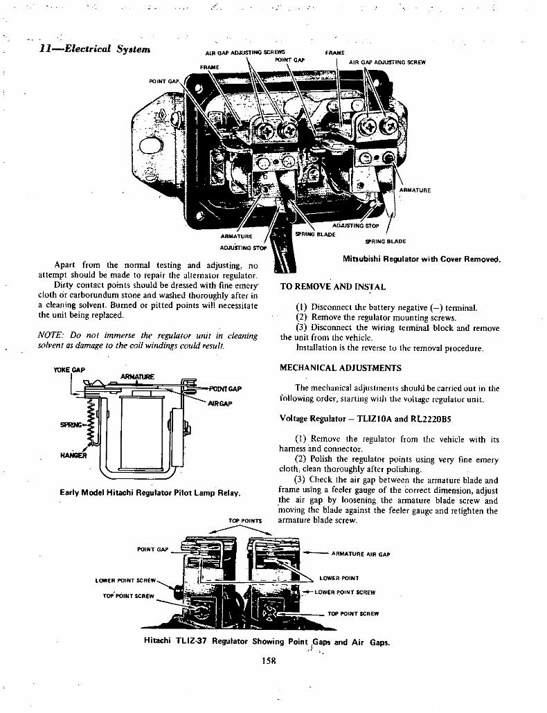
TOP POINTS
J
dIi LOWER POINT
ll Electrical Sy tem
Apart from the normal testing and adjusting no
attempt should be made to repair the alternator regulatorDirty contact points should be dressed with fine emery
cloth or carborundum stone and washed thoroughly after ina cleaning solvent Burned or pitted points will necessitatethe unit being replaced
NOTE Do not immerse the regulator unit in cleaningsolvent as damage to the coil windings could result
YOKE GAP
LlIIlE
JHANGER
lo GAP
A1RGAP
Early Model Hitachi Regulator Pilot Lamp Relay
POINT GAP
LOWER POINT SCREW
FRAME
AIR GAP ADJUSTING SCREW
ARMATURE
SPRING BLADE
Mitsubishi Regulator with Cover Removed
TO REMOVE AND INSTAL
1 Disconnect the battery negative terminal2 Remove the regulator mounting screws
3 Disconnect the wiring terminal block and remove
the unit from the vehicleInstallation is the reverse to the removal procedure
MECHANICAL ADJUSTMENTS
The mechanical adjustmellls should be carried out in the
following order starting with the vultage regulatur unit
Voltage Regulator TLlZ IOA and RL2220BS
I Remove the regulator from the vehicle with its
harness and connector2 Polish the regulator points using very fine emery
cloth clean thoroughly after polishing3 Check the air gap between the armature blade and
frame using a feeler gauge of the correct dimension adjustthe air gap by loosening the armature blade screw andmoving the blade against the feeler gauge and retighten thearmature blade screw
ARMATURE AIR GAP
LOWER POINT SCREW
TOP POINT SCREW
Hitachi TLlZ 37 Regulator Showing Point Gaps and Air Gaps
158

TOP POINT AOJUSTMENT SCREW
Electric l System 12
AIR GAP
RAME
IR GAP
VOLTAGE REGULATOR BOBBIN CORE
Hitachi TlIZ 37 Regulator with Cover Removed Showing Air Gap and Poi1t Adj stments
I Check the yoke air gap between the armature blade
and yoke frame using a feeler gauge of the correct
dimension adjust the gap at the annature set screw
2 Check the air gap between the bobbin core and
armature blade using a feeler gauge of the correct
dimension adjust the air gap by loosening the retainingscrew of the upper contact point blade and moving the
blade in the direction required using a screw driver
positioned in the adjusting slot
3 Check the point gap between the armature blade
point and the lower fixed point with the armature blade at
rest against the top point use a feeler gauge of the correct
dimension to check the gap and adjust the gap byloosening the point support screw and moving the point
ARMATURE BLAOE AIR GAP
support up or down to obtain the correct gap 0L
RELAY FRAMEPOINT GAP
I
rI i
t1 f
VOLTAGE REGULATOR ADJUSTING SCREW 1 l it r 7 1
J
LFhliHitachi TlIZ 37 Regulat r with Co er Removed Showing Regulator Adjusting Screws
4 Check the air gap between the bobbin core and
armature blade using a feeler gauge of the correct
dimension adjust by bending the primary contact supportbracket
5 Check the point gap with the armature at rest
using a feeler gauge of the correct dimension adjust the
point gap by bending the secondary contact supportbracket
Pilot Lamp Relay TLIZIOA
2
fr
f1f
ft
Voltage Regulator and Charge Relay TLIZ37
I Remove the regulator from the vehicle with its
harness and connector2 Polish the regulator points with very fine emery
cloth clean thoroughly after polishing3 Check the air gap between the bobbin core and
armature blade using a feeler gauge of the correct
dimension adjust the air g p by loosen ng the top pointsupport to frarpe retaining screw and move the pointsupport to give the correct air gap retightel1 the retainingscrew
4 Check the point gap with the armature at rest usinga feeler gauge of the correct dimension adjust the l int gapby loosening the lower point s pport retaining screw and
moving the point support to obtain the correct gapretighten the retaining screw
ELECTRICAL ADJUSTMENTS
Charge Relay
The charge relay check and adjustment is done with the
regulator removed from the vehicle
POINT GAP ADJUSTING SCREW
159

13 Electrical System
1I Djsconnecl the negative battery tenninal
2 Remove the regulator from the vehicle
3 Remove the c ver frolthe regulator4 Using a fully charged 12 volt battery connect a
O 3 ohm variable resistance with a switch in series betweenthe posi tive terminal and the N terminal yellow wireof the regulator wiring socket leave the switch in the off
position and the resistor at maximum5 Connect a 12 volt 3 watt globe in series between
the positive battery terminal and the L terminal redwith white trace wire of the regulator wiring socket
6 Connect the negative battery terminal to the Eterminal black wire ofthe regulator
7 Connect a 0 20 volt test voltmeter between the
regulator side of the variable resistor and the E terminal or
negative battery termn8 Turn on the switch and slowly reduce the
resistance of the variable resistor until the test lamp goesout note the voltage reading at this point which should bebetween 4 5 and 5 2 volts
9 To adjust turn off the switch turn the resistor to
maximum loosen the lock nut and screw the adjustingscrew in o increase and out to decrease the boltage atwhich the lamp will go out tighten the locknut after eachadjustment and recheck as in item 8
10 Afte the charge relay adjustment is completedremove the test instruments and wiring and instal theregu at f unit cover and instal the unit onto the vehicle
Voltage Regtlato TLlZIOA and RL2220BS
I Check the state of charge of the vehicle batteryshpuld it be under three quarters charged rech rge or
repl ce it with a fully charged one before the electrical tests
and adjustments are attempiedo
2 Disconnec t4e neg tive battery terminal3 Disconnect the wire rom the battery terminal on
th alternator4 Connect a 0 50 amp test animeter in series
between the disconnected wire and the alternator batteryterminal
5 Connect a 0 20 volt test voltmeter in parallelbetween the alternator battery terminal and a good earthsuch as the negative battery lead
6 ake sure t4e regulator unit is firmly mounted tothe vehi le and tJiat the wiring terminal connection is
firmly joined7 Connect a tachometer to the engine according to
the manufacturer s instructions
8 Reconnect the negative battery terminal andstart the engine and bring to operating temperature
9 Mount a thermometer on the cover of the regulatortl regis er the a bient temperature the thermometer can
be held in place with a lump of putty or similar substancec10 wJien the engine reaches operating temperature
and the ambient temperature reaches its maximum allowthe e gine to idle then slowly increase the rp and rote the
voltmeter reading which will rise with he engine speeduntil the regulator voltage is reached when the voltmeterneedle will give a sligl t kickback refer Specit1catiuns furcorrect setting
I I Increase the engine speed to approximately 2200
rpm and checc that the voltage reading remains within
Specification12 Should the voltage setting of the regulator not
meet with Specifications stop the engine and remove the
negative battery terminal remove the regulator cover
and bend the voltage regulator armature spring blade stopup to increase the voltage setting and down to decrease the
voltage selting
NOTE It is only necessary to bend the stop a minuteamount t alter the voltage setting
13 After making the adjustment replace the cover ofthe regulator reconnect the negative battery terminalan restart the engine
14 Repeat operations 9 to 13 until the correct
voltage setting is obtained
NOTE If the voltage build up of the aItemator cannot be
contrulled by the regulator it indicares thar the regulatorunit is at fault and should be replaced with a serviceableunit
lS After the voltage regulator adjustment has beencorrected stop the engine and disconnect the negativebattery terminal remove the test instruments andreconnect all wiring to the correct terminals reconnect the
negative battery terminal
Voltage Regulator TLlZ37
To check and adjust the voltage setting the regulatorunit should be installed in its mounted position on thevehicle
J Check that the regulator points are clean and freefrom pits or urn marks
2 Check the state of charge of the vehicle batteryshould it not he fully charged either charge it or replace it
with a fully charged one before the electrical tests andadjustments are attempted
3 Disconnect the negative battery terminal4 Disconnect the A terminal wiring from the
alternator and connect a 0 50 amp test ammeter and a
0 25 ohm resistor in series with the terminal anddisconnected lead bridge the resistor and ammeter with a
jumper lead to protect the ammeter until the alternatorcommences to charge
5 Connect a 0 20 volt test voltmeter between the Aterminal ofthe alternator and the negative battery terminal
6 Connect a tachometer to the engine according tothe manufacturer s instructions
7 Make sure an light switches and accessories are
turned off
160

8 Mount a thermometer on the cover of the regulatorto re ster the ambient temperature a cylindrical typethermometer may be held in place with a lump of putty or
similar substance9 Start the engine and allow it to reach operating
temperature10 Remove the jumper I d bridging the ammeter
resistor and increase the engine speed to approximately2500 rpm the ammeter reading should be less than 5 ampsafter a few minutes operation
lP With the engine operating at 2500 rpm check the
voltage reading on the voltmeter and note the ambient
temperature reading on the thermometer compare the
readings with Specifications12 If the voltage reading is not to specifications
allow the engine to idle and reconnect the jumper lead
bridge to protect the ammeter then stop the engine13 Remove the negative battery termjnal
14 Remove the regulator cover
Elec rical System 14
15 Reconnect the negative battery terminal
16 Start the engine again and remove the jumper lead
bridge17 Loosen the adjusting screw lock nut and turn the
adjusting screw in to increase t e reading arid out todecrease the reading Tighten the locknut after each
adjustment
NOTE The adjustment must be made within one minute
after the removal of the regulator cover as the change in
temperature occuring in the unit will alter the voltagesetting and the procedure will have to be repeated after the
unit has normalised with the cover installed
18 After the adjustment is completed stop the engineand remove the negative battery term nal disconnect
the test instruments and reconnect the alternator A
terminal and wiring19 Reconnect the negative battery terminal
DESCRIPTION
4 STARTER MOTOR
The starter motor is a 12 volt series wound four polefour brush or two brush unit
The starter motor is equipped wi a solenoid actuated
pre engaging starter drive and over running clutch assemblyThe solenoid is attached to the start r frame the solenoid
plunger is connected to the over running clutch and driv
pinion assembly through a link lever and pivot pin
arrangementWhen tpe solenoid windings are energised the plunger
acting on the lever and pivot engages the drive pinion with
the flywheel ring gear and at the same time closes the
switch supplying power from the positive lead of the
battery to the starter motor field coils to operate the
motor
As he engine fires the over runrung clutch of the drive
pi1ion assembly prevents high speed rotation of and
possible damage to the starter armature if the solenoid
wjndings are not immediately de energised by releasing theswitch key
The startersolenoid switch windings are energised byt e key operated combination ignition and starter switch
TO TEST ON THE VEHICLE
Should the starter fail to operate when the switch is
moved to the start posipon che k the following pointsi Check the battery condition and slate ofcharge
refer to batt ry section of this ITlanuaL
YOKE WINDOWS
DR V END BRACKETY KE
18 lEVER J
iiJhf
SO NOID JQCDVERZJ BRUSH TERMINALS
SPLIT PIN
SOLENOID SCREWS 0
c YPIVOT PIN
WASHERSCENTRE BRACKET
RETAINER CIRClIP
iARM TURE
BRUSH PLATE
b IP 4JI t i ICOLLAR 0 t n
roY
THRDUGH BOLTS BRUSHES Lta
BRUSH SHEW
Exploded View of Hitac i Starter Motor
161
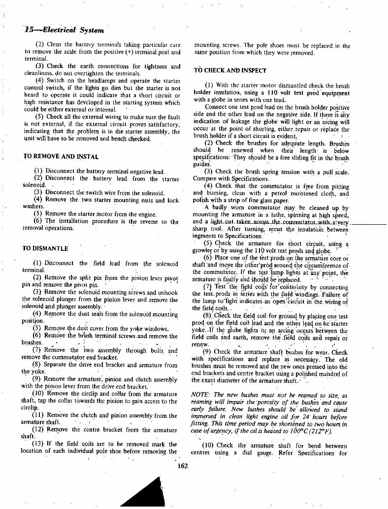
15 Elecfrical Sytem
2 Clean the battery terminals taking particular care
to remove the scale from the positive terminal post and
terminal3 Check the earth connections for tightness and
cleanliness do not overtighten the terminals4 Switch on the headlamps and operate the starter
control s tch if the lights go dim but the starter is not
heard to operate it could indicate that a short circuit or
high resistance has developed in the starting system whichcould be either external or internal
5 Check all the external wiring to make Sure the faultis not external if the external circuit proves satisfactoryindicating that the problem is in the starter assembly theunit will have to tie removed and bench checked
TO REMOVE AND INSTAL
I Disconnect the battery terminal negative lead2 Disconnect the battery lead from the starter
solenoid3 Discunnect the switch wire from the solenoid4 Remove the two starter mounting nuts and lock
washers5 Remove the starter motor from the engine6 The installation procedure is the reverse to the
removal operations
TO DISMANTLE
I Disconnect the field lead from the solenoidterminal
2 Remove the split pin from the pinion lever piyotpin and remove the pivot pin
3 Remove the solenoid mounting screws d unhooktpe solenoid plunger from the pinion lever and re ove thesolenoid and plunger assembly
4 Replove the dust seals from the solenoid mountingposition
5 Remove tpe dust cover from the YOle windows6 Remove the brush terminal screws and remove the
brushes
7 Remove the two assembly through bolts andremove the commutator end bracket
8 Separate th drive end bracket and armature fromthe yoke
9 Remove the armature pinion and clutch assemlywith the pinion lever from the drive end bracket
10 Remove the circlip and collar from the armatureshaft tap the collar towards the pinion to gain access to thecirclip
II Remove the clutch and pinion assembly from thearmatlre shaft
12 Remove the centre bracket from the armatureshaft
13 If the field coils are to be removed marl thelocation of each individual pole shoe before removing the
mounting screws The pole shoes must be replaced in thesame position from which t ley were removed
TO CHECK AND INSPECT
I With the starter motor dismantled check the brushholder insulation using a 110 volt test prod equipmentwith a globe in series with one lead
Connect one test prod lead on the brush holder positiveside and the other lead on the negative side If ihere is allyindication of leakage the globe will light or an arcing willoccur at the point of short ng ei1l1er r pair or replace thebrush holder ifa short circuit is evident
2 Check the brushes for adequate length Brushesshould be renewed when their length is belowspe itcations Theys ould be a free sliding fit in the bguides
3 Check the brush spring tension with a pull scaleCompare with Specifications
4 Check that the commutator is f e from pitlingand burning clean with a petrol moistened clotandpolish With a strip of fine glass paper
A badly Yom commutator may be cleaned up bymounting the armature in a lathe spinning at high speedand a lighLcuLtaken ac JSSiIe commutatOLWillLa yefJsharp tool After turning r cut tlJe insulation betweeiisegments to Specifications
5 Check the armature for short circuit using a
growler orby using the 110 volt test prods and globe6 Place one fthe t srprods on the arniat re Core or
shaft and moye t e other proarounq ipe cif umference ofthe commutator If the test lamp lights at any point thearmature is faulty ahd should be replaced
7 Test the nFld c04s tor cohtinuity by connectjngthe test prods in series with the field windings Failure Ofthe lamp to light indicat s an open brcuit in the wiring ofthe field coils
8 C eck the fjelq coil for grounq by pla ing one testprod on the field coil lead anthe other lead on he starteryok If the globe lights or arcing occurs between thefield coils and earth remove the field coils ana repair or
renew
9 Check the armature shaft bushes for wear Checkwith speCifications and replace as necessary The oldbrushes plust be removed and the pew ones pressed illto theend brackets and centre bracket using a polished mandrel ofthe exact diameter of the armature shaft
NOTE The new bushes must not be reamed to size as
reaming will impair the porosity of the bushes and cause
early failure New bushes should be allowed to standimmersed in clean light engine oil for 24 hours beforefitting This time period may be short ned to two hours incase ofurgelcy i the oil is heated to Jooe 2120F
10 Check the armature shaft for bend betweencentres using a dial gauge Refer Specifications for
162

I
1
Electrical System 16
Showing Method of Measuring Protruding length of Plunger from Solenoid Face to Adjusting Nut
tolerances Replace the armature if it is not within
SpecificationsII Check the drive assembly clutch pinion teeth for
wear scoring or chipping A clutch in good condition
should take up the drive in one direction only lt shouldrotate easily and smoothly in the non drive direction and
the assembly should move smoothly along the armature
helical splines
NOTE Do not wash the drive assembly or clutch in solvent
as this will destroy the clutch lubricant and cause early
failure of the unit
12 To replace the thrust plate and spring remove the
circlip from the sleeve while compressing the spring with
the thrust plate13 Check the ring gear for chipped worn and or bent
teeth replace as necessary
TO ASSEMBLE
I Lubricate the drive assembly on the armature shaft
splines armature shaft bushes and solenoid switch movingstud with a light coating ofmulti purpose grease
2 Instal the centre bracket to the armature shaft
3 Assemble the clutch and pinion to the shaft fit the
collar with the cup away from the pinion fit the circlip and
stake in position and fit the collar over the circlip4 Check the protruding length of the plunger
adjusting nut by pressing the solenoid plunger against a fiat
surface to completely depress the plunger measure the
distance from the face of the solenoid to the face of the flatsurface adjust the adjusting nut to give the correct
measurement Refer Specifications5 Assemble the armature start r clutch pinion lever
and cen trebracket to the drive end bracket
NOTE Make sure the thrust washer assgmbly and the lever
are correctly meshed
6 Instal the armature and drive end bracket assemblyto the yoke
7 Instal the commutator end thrust washers to the
armature shaft8 Instal the brush plate bracket and through bolts9 Tighten the through bolts and check the armature
end float Refer Specifications adjust with shiIns at
corrmutatoT end
163
I

17Electrcal System
Hitachi Starter Motor Showing Pinion to Pinion Stop Clearance
10 Instal the brushes into their correct holders andfit their tenninal screws and tighten
II Instal the solenoid dust seals and the solenoid
plunger tu the pinion lever invert the starter to allow the
pinion lever to move into position to instal the pivot pinmove the solenoid to align the pivot pin hules and instal the
pivot pin fit the solenoid mounting screws and tighteninstal the split pin to the pivot pin
12 Instal the dust cover over the yoke windows
TEST AND ADJUST
Starter Solenoid
The solenoid unit should be tested with the unit
mounted on the starter motor and connected in its
operating position but with the starter field lead
disconnected
I To test the series coil mount the starter motor
securely in a vice connect the negative terminal of 3 fullycharged 12 volt baltety to the M terminal of the solenoid
using a suitable jumper lead2 Make an 8 volt tapping on the battery and connect
a jumper lead with a switch in series to the solenoid S
terminal3 Close the switch the solenoid should be activated
and the plunger pulled smartly into the solenuid moving the
pinion assembly forward on the shaft4 To test the hold in coil connect the solenoid case
to the negative battery tenninal energise the solenoid as for
the series coil test then remove the M terminal connection
The solenoid plunger should remain held in the solenoid if
the hold in winding is serviceable5 To check the pinion to pinion stop clearance
energise the solenoid as above to move the pinion into its
mesh position
6 Measure the clearance between the pinion and the
pinion stop Refer Specifications for the correct clearance
NOTE Only hold the solenoid energised long enough to
make the measurement as damage to the solenoid could
occurfrom overheating
7 If the pinion to pinion stop clearance is notwithin
specifications remove the solenoid and adjust the plungeradjusting nut instal the solenoid and recheck the clearance
repeat the operation until the clearance is within
Specifications8 When he pinion to pinion stop clearance is
correctly adjusted remove the jumper leads and connect the
field wire to the terminal of the solenoid
Starter Motor
I Proceed with the noload test after checking and
adjusting the solenoid and pinion clearance2 Connect an ammeter capable of reading 0 500
amps in series with the positive battery terminal and the
solenoid B terminal using heavy core cable
3 Earth the negative battery terminal to the starter
body using heavy core cable4 Bridge the B terminal and the S terminal of the
solenoid using a jumper lead with a switch connected in
series5 Connect a revolution counter to the armature
shaft6 Close the switch in the jumper lead between the B
and S terminals and note the rpm and current draw of the
164

starter motor compare the readings with specifications7 After completing the starter test remove the test
instruments and leads
NOTE High amperage reading with low revolu tions check
for shorted armature shorted fields worn bushes bellt
armature shaft or poling armature high amperage draw
with no revolutiolls check for shorted field coils shortedarmature or shorted brnshes
Electrical System 18
To carry out the lock torque test mount the startermotor on a starter test bench and make the connections
according to the manufacturer s instructions use a highamperage variable resistor in the battery circuit so that the
voltage can be controlled accurately as small variations in
voltage and amperage can considerably alter the torque of
the starter motor Refer Specifications for the correct test
figures
DESCRIPTION
5 DISTRIBUTOR
The distributor is driven by a skew gear from the
camshaft Mechanical advance and vacuum advance systemsare incorporated in the distributor Mechanical advance is
by centrifugal weights mounted to the shaft and governedby one advance spring on all models except 0411 61
which has two advance control springsThe vacuum advance consists of a diapragrn unit
mounted externally onto the distributor body with linkageto the breaker plate from the diaphragm advance is
controlled by engine loadings
TO CLEAN AND ADJUST BREAKER POINTS
At intervals of 4000 km 3000 miles the contact
breaker points should be checked for excessive burning and
MOVING POINT
CONTACT POIN
FIXED POIN
ADJUSTING SCRE
I
pitting arid the dwell angle should be checked and adjustedif necessary
Points that are badly pitted and burned should be
replaced Points that are still serviceable should be cleaned
to a smooth square surface on a fine oil stone Remove all
traces of oil from the points by washing them in petrol as
oil or grease on the points will cause pitting and burningI To remove the breaker points firstly remove the
distributor cap and rotor button then loosen the low
tension lead screw on the fixed point and slide the wire
terminal from behind the screw
2 Loosen the fixed plate retaining screws do not
remove the screws
3 Slide the breaker point assembly away from the
retaining screws and adjusting screw at the same time lift
the breaker points clear of the distributor
LOW TENSION PIG TAIL
LOW TENSION TERMINAL
RETAINING SCREW
RETAINING SCREW
DIAPHRAGM LINK
MOUNTING SCREWS Distributor with Cap and Rotor Removed
165

19 Eleclrical Syatem4 To instal the breaker points rever e the removal
procedureS Turn the engine until the rubbing block of the
moving contacts is on the highest point of the cam lobe6 Slightly loosen the tixed contact plate lock screw
and using a suitable screwdriver move the contact plate in
the necessary direction until a clean feeler gauge blade ofthe specified thickness is a neat sliding fit in the point gapthen retighten the contact plate lock screw Again checkthe fit of the feeler gauge blade between the contact points
ROTOR OECLII
SCREWSCREW
MOVINGPOINT
FIXEDpOINT
8REAKERPLATE
EARTH PIGTAll
SCREW l
CLlP
VACUUM ADVANCE UNIT
SHMT AU
SPACER WASHER
P1G TAIL
oSHIMS
VI
PLATEaORING SEAL 0
CAPACITOR SCREWS
1
CLIP
REW
f
0THRUST WASHER
PINDRIVE GEAR
Exploded View of the Distributor Component Model
041161 Distributor u two Control Springs
Non If new poinls are being filled set Ihe gap allhe
upper limit of the specifications as the initial wearofa new
breaker arm rubbing bluck will be rapid If thepoinlS havebeen in use for some time but arestill sen iceable set the
gap at approximatelv mid way betlveen the upper and
lower limits of the specifications
7 Turn the engine and measure the contact poiot gapat each earn lobe being sure that the heel of the breaker
arm rubbing block is in the position of maximum lift on
each cam
8 Measure the breaker arm pressure with a springtension tester by pulling at right angles with the breaker
points see SpeciHcations9 Place a smear of high melting point grease on the
lobes of the earn assembly and instal the rotor arm and the
distribotor cap
10 Connect the dwell meter and check the contact
dwell adjust if necessary to specificationsII Connect the timing light and check the ignition
timing
TO REMOVE
I With the distributor cap removed turn the engineuntil the ignition timing mark indicates number one
cylinder is on tdc that is with the pointer in line with the
extreme left hand mark on the pulley when looking at the
engine from the front of the vehicle and the rotor button in
line with number one high tension lead tennina position2 Remove the vacuum advance line from the vacuum
advance control unit
3 Remove the primary ignition lead from the
terminal block4 Remove the set bolt holding the mounting plate to
the engine block and remove the distributor from the
engine
TO DISMANTLE
I Remove the rotor button2 Remove the vacuum advance control unit
mounting screws disconnect the linkage from the
diaphragm to breaker plate and remove the advance unit
3 Loosen the contact breaker point retaining screws
and terminal screw slide out the wire terminal and remove
the contact breaker points4 Remove the E clip from the moving point pivot
post and separate the breaker points5 Remove the low tension terminal block and
capacitor from the distributor body6 Remove the two screws holding the fIXed breaker
plate to the distributor body and remove the breaker plateassembly
7 To dismantle the breaker plates compress the
spring to gain access to the circlip and remove the circlipand spring taking care not to lose the balls between the
spring and plate and the two breaker plates
166
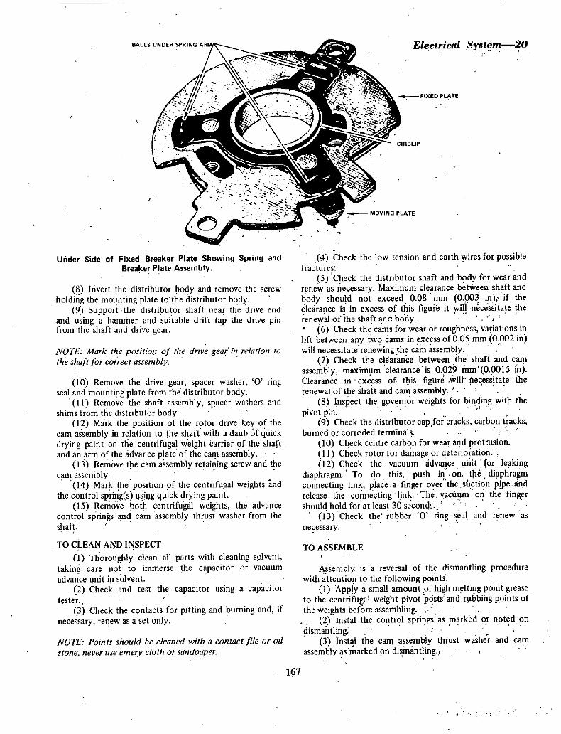
BALLS UNDER SPRING AR
I
Under Side of Fixed Breaker Plate Sho ing Spring and
Brea er Plate Assem ly
8 Invert the distributor body and remove the screw
holding the mounting plate to the distributor body9 Support the distributor shaft near the drive end
and using a hammer and suitable drift tap the drive pinfrom the shaft and drive gear
NOTE Mark the position of the drive gear in relation to
the shaft for co ect assembly
10 Remove the drive gear spacer washer 0 ringseal and mounti g plate from the distributor body
II Remove the shaft assembly spacer washers and
shims from the distributor body12 Mark the position of the rotor drive key of the
cam assembly in relation to the shaft with a daub of quickdrying paint on the centrifugal weight carrier of the shaft
and an arm of the advance plate of the earn assembly13 Remove the earn assembly retaining screw and the
cam assembly14 Mark the position fthe centrifugal weights and
the control spring s using quick drying paint15 Remove bofu centrifugal weights the advance
c mt olsprings and carn assembly thrust washer from the
shaft
TO CLEAN AND INSPECT
I Thoroughly clean all parts with cleaning solvent
taking care lot to immerse the capacitor or vacuum
advance unit ip solvent
2 Check and test the capacitor using a capacitortester
3 Check the contacts for pitting and burning and if
necessary re was a set only
NOTE Points should be cleaned with a contact file or oil
stone never use emery cloth or sandpap r
El ctrical Syatem 20
CIRCLIP
M Check the low tension and earth yires for possiblefractures
S Check the distributor shaft and body for wear and
renew as necessary Maximum clearance betweel1 s4aft and
body should not exceed 0 08 mm 0 p03 in if the
clearance is in excess of this figure it will necessitate the
renevial of the shaft and body6 Check the cams for wear or roughness variations in
lift between a y two cams in excess of0 05 mm 0 002 in
will necessitate renewing the c m assembly7 Check the clearance between the shaft and earn
assembly maximum clearance is 0 029 mm 0 0015 illClearance in ex ess of this figure will necessitate therenewal of the shaft and earn assembly
Inspect the governor weights for binding wit the
pivot pin9 Check the distributor cap for cr cks carbon tracks
burned or corroded terminal
10 Check centre carbon for wear a d protrusionI I Check rotor for damage or terioiation
12 Check the vacuum adv ce mut for leakingdiaphragm To do this push in on tpe diaphragmco ecting link p lace a fmger ave the s ction p pe andrelease the connecting link The vacuum on the fingershould hold for at least 30 seconds
03 Check the rubber 0 ring eal anq renew as
necessary
TO ASSEMBLE
Assembly is a reversal of the dismantling procedurewith attention to the following points
i Apply a small amount of high melting point greaseto the centrifugal weight pivot posts and rubbing points of
the weights before assembling2 Instal the control spri gs as marked or oted on
dismantling3 Instal the cam assembly thrust washer and am
assembly as marked on di mantling
167

21 Electrical Sy8fent
VOTE Un all Slflg C CUlrm sprillg HtJJl ls check IWI the
long slot in the com assembly udJ ilnce plate is jiued to the
weight with the cOIJtro spring arrilcheJ ami the shorr slot is
fitted to the weight without the control spring011 dual control sprmg mudels the shvneH sprmg is
attached to the centrifugal weight which is installed into
the long sJot of the cam assembly advance plate and the
longer spring is fitted lO the weight which is installed intu
the short SIOl of the advance plate
4 Instal the cam assembly retaining screw and
tighten5 Place the washers on the distributor shaft and
instal the shaft into the housing
NOTE Starting from the top the washers are ill the
following order washer bakelite washer and adjustingwasher Lubricate the shaft with engine oil before installing
6 Instal the muunting plate and the 0 ring seal to
the distributor body and instal the moun ting plate to
distributor body screw with the scale at the centre positiontighten the screw
7 Instal the drive gear and thrust washer on the shaft
and align the marks made on dismantling instal the drive
pin8 Measure the end thrust of the shaft with a feeler
gauge or dial gauge the end l10at should nut exceed 0 40mm 0 015 in If the end fluat exceeds the maximum
restore to the correct clearance by installing a suitable
adjusting washer9 Assemble the breaker plates and lubricate the balls
between the plates and between the spring and lower platewith high melting point grease
10 Instal tbe breaker plates and fit the retainingscrews
11 Instal the vacuum advance unit and connect thelink t9 the pin on the moveable plate and lightly lubricatewith hi melting point grease
12 Instal the capacitor terminal connections earth
pigtail wire and cap retaining clips13 Lightly lubricate the pivot post of the contact
breaker set and assemble ie breaker points14 Instal the breaker points onto the breaker plate
lightly lubricate the carns and apply a small dab of highmelting point grease to the rubbing block of the movingpoint
J 5 Adjust the contact breaker gap as described in the
section TO CLEAN AND ADJUST BREAKER POINTS16 Instal the rotor button and check that the
centrifugal weights are free to operate by turning the rotor
button against the centrifugal control spring while holdingthe drive assembly when the rotor button is released it
should return freely to the fully retarded position17 If the rotor is inclined to stick or does not return
to the retard position the cause should be located and
rectified
Tdc Timing Mark on Crankshaft Pulley in Line with
Pointer on Timing Cover and Distributor Rotor at No 1
Cylinder Firing Point
TOIN TAL
J Check that the engine has not been rotated after
the distributor was removed by rechecking the timingposition as described in item I of the TO REMOVE
section
2 Turn the distributor shaft 50 that the rotor button
points to the position of the high tension terminal for
number one cylinder then turn the rotor in 3 clockwise
direction sufficiently to move the gear one tooth
3 Instal the distributor into its mounting hole
making sure that the drive geat is fully engaged and that
the rotor button is pointing to the cap clip aI1d the positionof the high tension terminal for number one cyUnder instal
the mounting plate to engine retaining bolt
4 Check that the contact breaker points are juststarting to open when the e3rn assembly is turned in the
direction of rotation and tighten the mounting plate to
engine retaining bolt5 Instal the distributor cap and connect the spark
plug leads6 Instal the low tension lead
168

7 Check the ignition timing with a timing light and
check and adjust the dwell angle if necessary8 Instal the vacuum advance line
TO TIME ENGINE AND SET IGNITION TIMINGStatic method
1 Ensure that the contact breaker points are clean
and adjusted to the specified clearance2 Rotate the crank haft until No 1 piston is at tdc at
the end of the compression stroke3 Align the pointer on the timing cover with the
extreme left hand mark on the crankshaft pulley when
viewing the pulley from the front of the car
4 The position of the rotor should be in alignmentwith No I high tension lead terminal of the cap and the
contact breaker points should be just starting to open5 To adjust loosen the anchor plate to mounting
bracket screw and move the distributor body in the
direction required then retighten the screw
6 Road test the vehiCle and make final adjustmentsto obtain best performance and smoothest operation
TO ADJUST IGNITION TIMING AND DWELL ANGLE
Using instruments
1 Connect a tachometer dwell meter and timinglight to the engine according to the manufacturer s
instructions
2 Start the engine and bring to normal operatingtemperature
3 Adjust the engine igle speed to specifications
Electrical System 22
4 Disconnect the vacuum line from the vacuum
advance unit and check the advance position with the
timing light each division on the crankshaft pulley equals 5
degrees refer specifications for the correct setting5 Adjust the timing position by loosening the
mounting plate retaining bolt and rotate the distributor
body in the slot if the adjustment is not possible at this
point it will be necessary to loosen the screw holding the
mounting plate to the distributor body both these screw
holes are elongated for this adjustment6 After the COffect timing position has been
determi ed make sure the mounting plate to engineretaining bolt and the mounting plate to distributor bodyscrews are firmly tightened
7 Check the contact dwell refer Specifications for
the correct setting adjust by opening or closirig the contact
breaker pain t gap the engine will have to be stopped and
the distributor cap and rotor button removed to carry out
this operation8 After setting the contact dwell at idle speed
increase the engine speed t0 approximately 2500 rpm
checking the dwell angle as the rpm s increase Anyvariation greater than specifications indicate orn partswithin the distributor in which case the distributor will
have to be removed for uverhaul9 After checking and adjusting the dwell angle
recheck the ignition timing and adjust if necessary10 Reconnect the va uum advance line and adjust
the engine idle to speCifications11 Remove the test instruments and reconnect any
disconn ctcd wiring etc
POINTER
IGNITION TIMING MARKS
Showing Ignition Timing Marks and Distributor Advance and Retard Scale
169

23 Erectriea Sy nt
TO SERVICE
8 SPARKIXf PLUGS
The spark plugs should be removed for inspectioncleaning and resetting at intervals of 5 000 to 6 000 km
3 000 to 4 00Q miles
Spark plugs removed from an engine in good condition
operating under nonna conditions should have a lightpowdery deposit ranging in colour from liglit brown to
greyish tan After considerable service the electrodes will
show signs of wear or nOllllal buming Spark plugs showinga thick black oily deposit indicate an engine in poormechanical condition or possibly that a plug with too low
a heat range has been fitted
Spark plugs howing a white or yellowish depositindicate sustained high speed driving or possibly that plugs
of too high heat range have bC1l tIued particularlv when
these deposits are accompanied by blistering of the
pon elain and burning 01 the eletrodes
If the heat range is correct clean the plugs on a sandingmachine and blow clean with compressed air
Set the electrode gap see Specifications by bendingthe earthing electrode s and test the plug on a reliable
testing machine
NOTE Neve attempt to set tlte electrode gap bv bendingthe centre electrode or a cracked insulator wiI result
Clean the spark plug threads and using new gaskets fit
the plugs finger tight Using a torque wrench tighten to the
recommended torque Refer Specifications
7 HIGH TENSION UlADS
The high tension cables between the sparking plugs and
the distributor cap and the centre high tension terminal on
the distributor cap and the ignition coil are of specialmanufacture and have a carbon impregnated core instead of
the normal wire core
This is to eliminate radio interference care must be
exercised when removing the cables from the sparking plugsto ensure that the cables are not damaged by stretchingwhich will break tlie core and render the cable
unserviceable
Always r move the cable from a sparking plug bypulling on the cable terminal Use the same care when
connecting the cable to the plugIf a cable has a broken core it will cause misfiring
Check the cables for perishing or cracking and renew as
required Never attempt to repair defective cables
The cables may be carefully cleaned using a cloth
moistened with kerosene then wiping completely dryAlso check the distributor cap for cracks or tracking
between the high tension tenninals on both the inside and
outside of the cap Renew the cap if cracks or tracking is
evidentCheck the carbon brush in the centre of the distributor
cap for evidence of arcing and renew as necessary
8 IGNITION COli
Two types of primary ignition circuits are used on
these vehicles the simple circuit and a series resistance
circuitThe primary circuit which does not include a resistance
between the ignition switch and coil uses a normal 12 volt
coil and a simple primary circuit
When a series resistance is incorporated in the primarycircuit a special 12 volt coil is used which is marked to be
used with a series resistanceThe series resis ance is mounted near the coil and when
used cannot be overlooked or disregarded when the primarycircuit is being checked disconnected or connected
When the series resistance is used in cunjunction with
the special coil a high secondary voltage is obtained
throughout the speed range of the engine resulting inbetter performance of the vehicle The series resistance is
by passed when the ignition switch is moved to the start
position by an internal bridge in the ignition switch which
brings in a secondary primary circuit This secondary circl it
allows a full 12 volt pressure at the coil terminal resulting ina stronger spark for starting purposes as any voltage dropcaused by the heavy starter draw is automaticallycompensated for by the circuitry
DESCRIPTIOND TURN SIGNAL Sl ITfH IIIlADI OT DIPPER AND HORN BUTTOX
HORN BUTTON
The turn signal switch is a multi purpose unit
comprising switch mechanism for the turn signal lamps with
automatic cancelling the headlight dipper switch a highbeam flasher contact for overtaking and the hum wiringcontacts for the horn button circuit
To Remove and Instal Early Model 1000
I Disconnect the battery negative tenninaL2 Pull out and remove the horn button medallion
3 Remove the horn button retaining ring
170

4 Remove the steering wheel retaining nut lock
washer and flat washer
5 Remove the horn bar assembly from the steeringwheel
6 Remove the three springs from under the insulator
ring7 To dismantle the horn bar remove the three
assembling screws
8 Separate the insulator ring horn contact seat
contact plate and the insulators between the horn bar and
contact plate9 Remove the steering wheel using a suitable puller0 Remove the screws holding the turn signal trip
insert and remove the horn contact slip ring and trip insert
Assembly and installation is a reversal of the removal
and dismantling procedures
To Remove and Instal Later Model 1000
1 Disconnect the battery negative terminal2 Press in on the horn button and turn in an
anti clockwise direction to release it from the retainer
3 Remove the horn button spring4 Remove the three screws holding the retainer plate
to the steering wheel hub and remove the retainer plate
HORN BUTTON
Electrical System 24
5 To dismantle the horn button remove the three
screws and the non conductive retaining blocks from the
horn button
6 Remove the contact plate and sponge rubber ringfrom the horn ring
7 The assembling and installation procedure is the
reverse to removal and dismantling operations
To Remove afd Instal 1200
I Disconnect the battery negative terminal
2 Remove the two screws holding the horn button
and medallion assembly to the steering wheel working from
the underside of the wheel3 Raise the button and medallion assembly from the
steering wheel and disconnect the horn wire from the
terminal in the steering wheel hub remove the button and
medallion4 To remove the thumh press buttons from the
medallion remove the two E clips retaining the thumb
press button to the medallion and remove the button
5 Remove the nut washers and wiring terminal from
he centre terminal screw
RETAINER SCREWS
QUADRANT ASSY
HOUSING
WEDGE
JSTEERING SHAFT
tJACKET
UJ II COVER
LEVER COVER SCREWS
Dismantled View of Top of Steering Column Automatic
Transmission later Model 1000
Dismantled View of Horn Contacts Early Model 1000
171
r Q NToLE
WAHERIe
I INSULATOR RING
10 1SPRINGS SCREWS INSULATORS NUT

Iju 2 Electrical SY3tem
6 Remove the insulation bIOl k H spring andcontact assembly
Installation is a reversal of the removal procedure
TURN SIGNAL SWITCH
To Remove and Instal
I Disconnect the negative battery terminal2 Remove the horn button assembly and retainer
where used
3 Remove the steering wheel retaining nul andwasher and remove the steering wheel
4 Remove the horn contact rubbing plate from theunderside of the steering wheel and remove the contact
spring and plunger5 Remove the Screws holding the two halves of the
steering column cover together and remove the cover
6 On automatic transmission models disconnect thequadrant light wires and remove the quadrant assembly
7 Disconnect the turn signal wiring at the terminal
connecting block at the dash panel8 On 1000 models loosen the mounting screw in the
top of the switch and tap downwards to release the locatingwedge remove the switch from the steering jacket
9 On 1200 models remove the switch retainingscrews from the clamp loosen the switch from the steeringjacket to free the locating peg and remove the switch fromthe steering jacket
Installation is a reversal of the removal procedure
I BUTTON
CONTACT
u rNG
flJINSUtTOR
SWITCH ASSY
uSCREWS
d
EClIP
Dismantled View of Turn Signal Switch Later Model 1000
WIRES TO BUTTONS
ECLlPS
WASHERS
NUTHorn Button and Medallion Assembly
Removed 1200 Models
HORN CONTACT View of Turn Signal Switch Assembled 1200 Models
172

Electrical Sy tem 26
HEADLAMP SWITCH
10 SWITCHES AND CONTROLS
INHIBITOR SWITCH
I Disconnect the negative battery terminal2 Press in on the switch knob and turn in an
anti clockwise direction to remove the knob from the rod
3 Remove the escutcheon nut using a specialremoving tool
4 Remove the switch from the rear of the panel5 Disconnect the wiring terminal block from the
switch and remove the switch
Installation is a reversal of the removal procedure
WINDSCREEN WIPER SWITCH
The removal and installation pro edure is the same as
for the head lamp switch
IGNITION SWITCH Standard Type
J Disconnect the negative battery terminal
2 Remove the switch escutcheon nut using a specialremoving tool on 1000 models remove the switch from the
dash panel on 1200 models remove the switch from the
switch bracket3 Disconnect the wiring terminal from the switch
and remove the switchInstallation is the reverse to the removal procedure
Steering Lock Type
When the ignition switch is turned to the lock positionand the key removed from the switch a plunger engagesinto a collar on the steering shaft locking the steering wheel
and shaftThe ignition switch is mounted onto the end of the
locking barrel and is replaceable without removing the
locking barrel and key assemblyl To replace the steering lock assembly use a
suitable drill to drill out the old shear type assembly bolts
2 Remove the two ordinary assembling screws fromthe bracket and remove the lock assembly
Installation is the reverse to the removal procedure bu t
new shear type mounting bolts should be used
Warning Buzzer
The buzzer switch is mounted to the steering lock
assembly and operated when the vehicle door is openedwhile the switch is in the unlocked position
The buzzer is mounted behind the dash panel on the
left hand side and is held in place by two screws
To remove the buzzer switch disconnect the wire
terminals
Remove the cover and remove the two mountingscrews
Installation is the reversal of the removal procedure
Refer to the AUTOMATIC TRANSMISSION section
for adjustmen t and service procedure
STOP LIGHT SWITCH
The 1000 model vehicles use a hydraulically operatedswitch which is mounted on the four way connection
attached to the engine firewall
The 1200 model vehicles use a mechanically operatedswitch which is mounted on a bracket under the dash paneland is operated by the brake pedal
Hydraulic Type
To remove the hydraulic type switch disconnect the
wires from the switch terminals and unscrew the switchfrom its mounting position
Installation is the reverse to the removal procedurewith the addition of bleeding the brake system as necessaryRefer to the BRAKES section for the bleeding procedure
Mechanical Type
To remove the mechanical type switch disconnect the
wires from the switch connections loosen the lock nut and
remove the mounting nut and the switchTo instal the stop light switch refer to the BRAKES
section of this manual under the sub heading BRAKE
PEDAL HEIGHT ADJUSTMENT 1200
NOTE DO NOT atTempr to adjusT the stop light swirch
unless the pedal height is checked and adjusted as aultv
brake uperatio could result
HANDBRAKE WARNING LIGHT
The warning light is operated by an earth switch
controlled bv the handhrakc lever when the handhrake is
applied tl l switch is dueu cllmplcting the warning lightcircuit when the handbrake is released the switch is openedbreaking the warning light circuit
The handbrake dash warning light indicator also acts as
the dual brake system warning light as both systems are
wired through the same dash warning light indicator
DUAL BRAKE SYSTEM WARNING LIGHT SWITCH
Description
The switch is a differential type pressure s vitch
Should a failure occur in either the front or rear brake
system the switch piston will be forced to the side with the
lowest pressure earthing the contact of the electrical
connection completing the circuit of the dash warning light
173
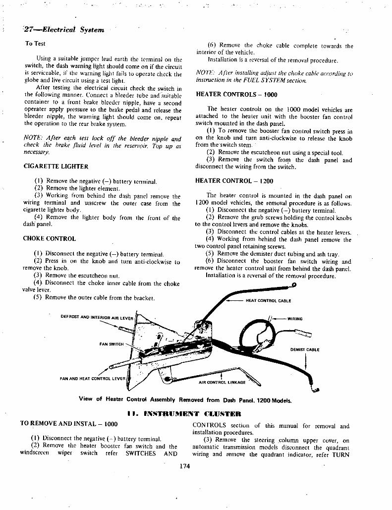
27 Electrical System
To Test
Using a suitable jumper lead earth the terminal on the
switch the dash warning light should come on if the circuit
is serviceable if the warning light fails to uperate check the
globe and live circuit using a test lightAfter testing the electrical circuit check the switch in
the foHowing manner Connect a bleeder tube and suitable
container to a front brake bleeder nipple have a second
operater apply pressure to the brake pedal and release thebleeder nipple the warning light should come on repeatthe operation to the rear brake system
NOTE After each test lock off the bleeder nipple and
check the brake fluid level in the resen oir Top up as
necessary
CIGARETTE LIGHTER
I Remove the negative battery terminal
2 Remove the lighter element3 Working from behind the dash panel remove the
wiring tenninal and unscrew the outer case from the
cigarette ligh ter body4 Remove the lighter body from the front of the
dash panel
CHOKE CONTROL
I Disconnect the negative battery terminal
2 Press in on the knob and turn anti clockwise to
remove the knob3 Remove the escutcheon nut
4 Disconnect the choke inner cable from the choke
valve lever
5 Remove the outer cable from the bracket
FAN AND HEAT CONTROL LEVER
6 Remuve the choke cable complete towards the
interior of the vehicleInstallation is a reversal of the removal procedure
NOTE 4frer installing adjust the choke cable according to
instruction in the FUEL SYSTEMsectiull
HEATER CONTROLS 1000
The hearer controls on the 1000 model vehicles are
attached to the heater unit with the booster fan control
switch mounted in the dash panel1 To remove the booster fan control switch press in
on the knob and turn anti c1ockwise to release the knob
from the switch stem
2 Remove the escutcheon nut using a special tool
3 Remove the switch froll the dash panel and
disconnect the wiring from the switch
HEATER CONTROL 1200
The heater control is mounted in the dash panel on
1200 model vehicles the removal procedure is as follows
I Disconnect the negative battery terminal
2 Remove the grub Screws holding the control knobs
to the control levers and remove the knobs
3 Disconnect the control cables at the heater levers
4 Working from behind the dash panel remove the
two control panel retaining screws
5 Remove the demister duct tubing and ash tray
6 Disconnect the booster fan switch wiring and
remove the heater control unit from behind the dash panelInstallation is a reversal of the removal procedure
AIR CONTROL 1INKAGE
View of Heater Control Assembly Removed from Dash Panel 1200 Models
11 INSTnUIlNT CI USTER
CONTROLS section uf this manual for removal and
installation procedures3 Remove the steering column upper cover on
automatic transmission models disconnect the quadrantwiring and remove the quadrant indicator refer TURN
TO REMOVE AND INSTAL 1000
I Disconnect the negative battery terminal
2 Remove the heater booster fan switch and the
windscreen wiper switch refer SWITCHES AND
174

SIGNAL SWITCH seciion of this manual for removal and
installation procedures4 Disctlfinect the speedo drive cable casing from the
speeao head
5 Move the instrument Cluster towards the steeringwheel arid disconnect the twelve point plug from the
prlnted circuit ter inals
6 Remove the instrument cluster from the dash
panelinst llation is a reversal of the removal procedure
TO REMOVE AND INSTAL 1200
ij Disconnect the negative battery terminal2 Re ove the radio control knobs and spindle
retaining ntits3 Remove the heater control knobs cigarette lighter
unit head light switch windscreen wiper switch and choke
Electrical SY3tem 28
control cable from the dash panel refer SWITCHES AND
CONTROLS section of this manual for removal and
in tal1 ati9n procedureseirove the steering column upper cover refer
TURN SIGNAL SWITCH section of this manual for
removal and installation procedures5 Remove the two screws holding the instrument
cluster to the dash panel models with round instruments
only hav o e screw holding the instrument cluster to the
dash panel6 Disconnect the speedo drive casing from the
speedo head
7 Move the instrument cluster towards the steeringwheel and disconnect the twelve point plug from the
printed circuit terminals8 Remove the instrument cluster from the dash panel
complete with cover panelInstailation is a reversal of the removal procedure
TO REMOVE AND INSTAL
12 WINDSCREll WIPER
I Disconnect the ne ative battery terminal
2 FroI1 under the dash panel on the left side remove
the wiper spindle to linkage retairiing nut and disconnect
the linkage3 Disconnect the wiring terminal connector at the
wipe r motot4 Remove the wiper motor retainirig bolts
5 Remove the wiper m tor from the vehicleInstallation is a reversal of the removal procedure with
partictiiar atiention being paid to the sealing between the
wiper spindle and vehicle body
NOTE The automaric parking posirion is not adjustableTheonly adjuslinent is bv the positioning of the wiper aims
on ihe spindles
toREMOVE AND INSTAL tHE PIVOT BOXES
I Disconnect the negative baitery terminal2 Remove the wiper arm to spindle retaining nuts
and remove the wiper arms and blades3 From under the dash panel remove the pivot box
retaining bolts and the wiper motor spindle to linkageretaining nut
Wiper Motor 1000 MOdelS
4 Remove the linkage and pivot boxes from the
vehicletIn tallatidn is a reversal of the reniov 1 procedure
p irgj articula care to the serviceability of the pivot box
to bodji seals
TO REMOVE AND iNSTAI HEADLAMP uNIT
I i I IP U ITS
1 r Disconriect the negative battery t rminai2 Remove the headlamp rim on all models except
coupes un tuupe mudels remuve the radiator grille
retaining screws and remove the grille3 Remove the headlamp retaining bezel screws
4 Remove the lamp unit and disconnect the wiring
plugInstallation is a reversal of the removal procedure
175
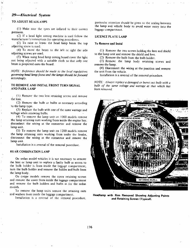
29Eleclrical Syslem
TO ADJUST HEADLAMPS
I Make sure the lyres are inflated to their correct
pressuresif a head hght aiming ma hine is u eJ follow the
manufacturer s instructions for operating procedures3 To raise or lower lhe head lamp beam the top
adjusting screw is used4 To move the beam to the left or right the side
adjusting screws are used5 When using head lamp aiming board cover the light
not being adjusted with a suitable cloth so that only one
beam is projected onto the board
NOTE Reference should be made to the local regulationsgoverning head lamp focus and the lamps should be focused
according v
TO REMOVE AND INSTAL FRONT TURN SIGNAL
AND PARK LAMP
I Remove the two lens retaining screws and remove
the lens2 Remove the bulb or bulbs as necessary according
to the lamp type3 Replace the bulb with one of the same wattage and
voltage when renewing bulbs4 To remove the lamp unit on 1000 models remove
the lamp retaining nuts working from inside the engine baydisconnect the wiring at the connector and remove the
lamp unit
5 To remove the lamp unit on 1200 models remove
the lamp retaining nuts working from under the fender
disconnect the wiring at the connector and remove the
lamp unit
lnstaHation is a reversal of the removal procedure
REAR COMBINATION LAM
On sedan model vehicles it is not necessary to remove
the lens or lamp unit to replace a faulty bulb as access to
the bulb holder is from inside the luggage compartment
turn he bulb holder and remove the holder and bulb from
the lamp bodyOn cotipe models remove the cover retaining screws
and remove the cover from inside the luggage compartment
and remove the bulb holders and bulbs as for the sedan
modelsTo remove the lamp units remove the retaining nuts
and washers from inside the luggage compartment
Installation is a reversal of the removal procedure
particular artention should be given to the sealing between
the lamp and vehicle body to avoid waler entry into the
luggage compartment
LICENCE PLATE LAMP
To Remove and Instal
I Remove the two screws holding the lens and shield
to the lamp unit and remove the shield and lens
2 Remove the bulb from the bulb holder
3 Remove the lamp body retaining screws and
remove the lamp4 Disconnect the wiring at the junction and remove
the unit from the vehicleInstaHation is a reversal of the removal procedure
NOTE 41wavs replace a damaged or burnt outbulb with a
bulb of the same voltage and wattage as thar which has
been removed
HeadJamp with Rim Removed ShoWing Adjusting Pointsand Retaining Screws Typical
176

Electrical Sy tem30
WIRING BODY SEAL LENS SCREWS
TURN SIGNAL INSERT
Exploded View of Front Parking lamp 1000 Model
PARK BULB TURN SIGNAL LENS
m
Exploded View of Front Parking lamp 1200 Model
jt
TURN SIGNAL LENS
REVERSE LAMP LENS
itREVERSE LAMP BULB
1 1r p
STOPTAIL BULB
fI
J@i4 0 G
4
7j tV SBODY TURN SIGNAL BULB
1MOUNTING NUTS AND WASHERS
BEZElL
ISEAL
Exploded View of Rea Combination lamp 1000 Models
BULB SOCKETS BOOY TURN SIGNAL BULB TURN SIGNAL LENS
fI sJTAIl BULB
1
LSEALS
D REVERSE LAMP BULB
L MOUNTING NUTS AND WASHERS
BEZEll
REVERSE LAMP LENS
Exploded View of Rear Combination lamp 1200 Models
177
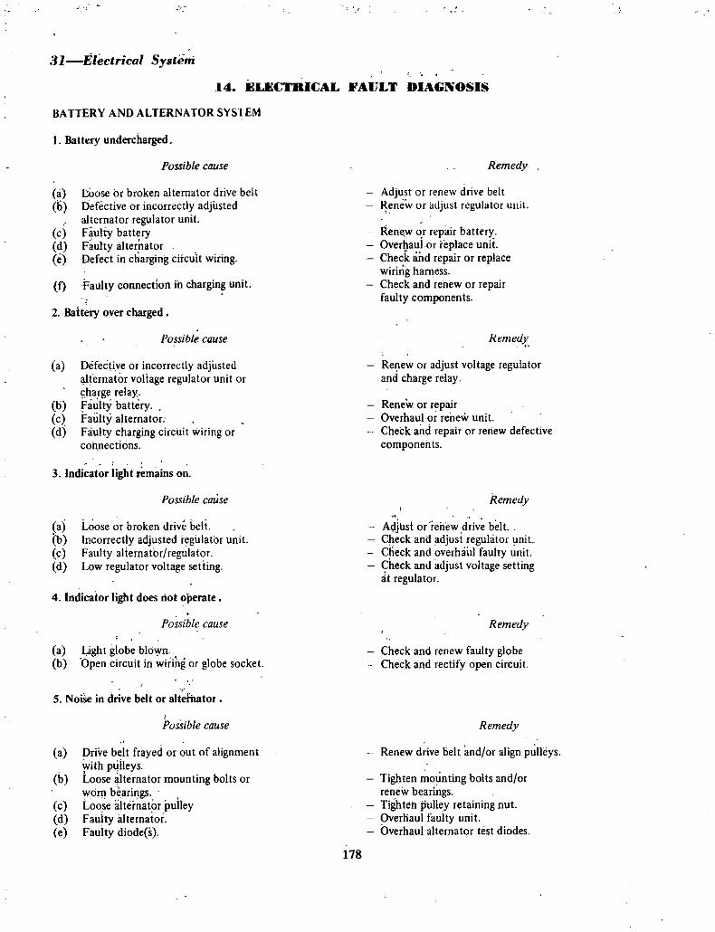
ll Electrical System
14 ELIlCTRICAL FAULT DIAGNOSIS
BA TTERY AND ALTERNATOR SYSTEM
Battery undercharged
Possible cause Remedy
a 1o0se or broken alternator drive belt
Ii Defective or incorrectly adjustedalternator regulator unit
c Faulty batteryd Faulty alternatore Defect in charging circuit wiring
f Falilty connection in charging unit
Adjust or renew drive belt
new or adjust regulator unH
Renfwor repair batteryOver auior replace unitCheck and repair or replacewiring harness
Check and renew or repairfaulty components
2 Baltery over charged
Possible cause Remed
Re ew or adjust voltage regulatorand charge relay
a Defective or incorrectly adjustedfernator voltage regulator unit or
sharge relayb Faulty batteryc Faulty alternatord Faulty charging circuit wiring or
connections
Renew or repairOverhaul or renew unit
Check and repair or renew defective
coniponents
3 Indicator light remains on
Possible caUse Remedy
a Loose or broken drive beltb Incorrectly adjusted regulator unit
c Faulty alternator regulatord Low regulator voltage seding
Aljl1s1 or renew drive belt
Check and adjust regulator lInitCheck and overhaul faulty unit
Check and adjust voltage settingt regulator
4 Indicator light does riot operate
Possible cause Remedy
a Light globe blownb Open circuit in wiring or globe socket
Check and renew faulty globeCheck and rectify open circuit
5 NoiSe in drive belt or alternator
Possible cause Remedy
a Drive belt frayed or out of alignmentwith puileys
b Loose alternator mounting bolts or
worr bearilgsc Loosealtemator pulleyd Fauity illternatore Faulty diode s
Renew drive belt and or align pulleys
Tighten mounting bolts and or
renew bearingsTighte pulley retaining nut
Overliaul faulty unit
Overhaul alternator test diodes
178

Electrical System J2
BA ITERY AND STARTING SYSTEM
1 Starter lacks power to crank engine
Possible cause Remedy
a Battery undercharged Check charging system and rectifyas necessaryCheck and repair or renew batteryClean and tighten terminalsCheck and overhaul starter motor
Check and renew solenoid as necessary
b Battery faulty will not hold chargec Battery terminals loose or corrodedd Faulty starter motor
e Faulty starter solenoid switch
or contacts
2 Starter will not attempt to crank engine
Possible cause Remedy
b Discharged batteryc Battery fully charged but will not
crank engine
Check for dirty or loose terminals dirtycommutator faulty solenoid faulty switchCheck for fault or short circuit in systemCheck for locked drive and ring gears internal
starter fault or seized engine
a Open circuit in starting system
IGNITION SYSTEM
IEngine will notstart
Possible cause
Remedya Fault in ignition primary circuit wiringb Fault in ignition switch
c Fault in coil primary windingd Burnt or dirty contact breaker pointse Faulty capacitor or capacitor lead
f Fused or broken wire between breakerarm and low tension terminal
g Fault in coil high tension circuit
h Cracks in distributor capi Crack in distributor rotor
OJ Faulty high tension leadsk Faulty or incorrectly adjusted spark plugs
Check circuit and repair as necessaryRenew ignition switchRenew coilClean and orrenew and adjust point so
Check and renew capacitorRenew low tension block and wires
Test and renew coil as necessaryRenew distributor capRenew rotor
Check and renew leadsRenew and or clean and adjust spark plugs
2 Engine starts but misfires underload
Possible cause Remedv
a Faulty dirty or incorrectly adjustedspark plugs
b Dirty or incorrectly adjustedcontact breaker
e Uneven wear on distributor earn
d Condensation oisture on inside or
outside of distributor cape Cracked spark plug insulator s
f Faulty ignition coil
Renew and or clean and adjust spark plugs
Clean and adjust points
Check and overhaul distributor
Check and dry out and examine for minute cracks
Renew faulty plugs
Renew or check coil
179

33 Electr cal System3 Engine runs but lacks power
Possible cause
a Ignition timing incorrectly set or
contact points require adjustingb Vacuum advance mechanism sticking or
excessively worn
c Vacuum advance unit inoperative
d Vacuum advance unit operates but
ineffective
AUTOMATIC TRANSMISSION 1000
ANO 1200 MODELS
1 Kickdown switch
2 Kickdown solenoid3 Fuse panel4 Ignition switch
5 I nhibitor switch
6 Starter motor and solenoid
7 Battery
G
n l8
C Ir
BY
11 Ills1
tJ1 7 I
COLOR CODE
G Green
B Black
RB Red with black tracer
BY Black with yellow tracer
Remedy
Check and readjust ignition timingand or contact pointsOverhaul distributor
Check for faulty vacuum pipe or faultyadvance unit
Advance unit link disconnected or
requires adjustment
DATSUN 1000 MANUAL TRANSMISSION
COLOR CODE
V
B
G
W
R
BL
WR
WB
RB
BW
VB
GV
BG
GBGR
VW
RW
GW
BR
BY
WBL
GBL
BBL
BLRBLW
BWtwBIG
180
Yellow
Black
GreenWhite
Red
Blue
White red tracer
Whiteblack tracer
Redblack
Black white tracer
Vellowblack tracer
Greenyellow tracer
Black green tracer
Greenblack tracerGreenred tracer
Yellow white tracerRed white tracerGreenwhite tracer
Black red tracer
Black yellow tracer
White blue tracer
Greenblue tracer
Black blue traeer
Blue red tracer
Bluelwhite tracer
Blackwhite tracerlwhite ideeve
Black green sleeve

G
T
L w
mF
1lFYy
N 1lE
I 2 1J 3 Dcrj W
T
or
@fIl2 C
28
r
y
ltB
e
7OC oJlG
1 Alternator
2 Aegulator3 4 Horns
5 Horn relay6Ignition coil
Distributor
S fuse panel9 Radio
10 Cigar lighter11 Windscreen wiper switch
12 Heater
13 Windscreen wiper14 R H reversing lamp15 R H turnsignal lamp16 A H stop and tail lamps17 Reversing lamp vans only18 Licen plate lamp
19 Interior lamp and switch
20 Courtesy lamp door switches
0
T11
y
iPllIL
f1Q A
ri3 ic1feD
wo0
l CtIDE B
i BIl2L
1 1 J
@ frJ
fpsJ1ss
O LII T L IBlrJi l RW it
f Jf 11lIiBD Jil 51R1
r Q
r
w
w
J
P
rN
I
Wiring Diagram for 1000 Models with Manual Transmission
1 Ignition switch
22 Lighting switch
23 Battery24 Starter motor and solenoid
25 R H fog lamp26 R H front side turn signal
lamp27 R H turn signal and parking
lamp28 Fog lamp switch
29 R H headlamp30 LH headlamp31 LH turnsignal and parking
lamp32 LH front side turn signal lamp33 L H fog lamp34 Turn signal and combination
switch35 T signal relay unit
181
Electrical System 34
fiW
w
Ig
CD 1p
T
wtfjjw
36 Engine temperature sender unit
37 Oil pressure warning tamp switch
38 High beam indicator lamp39 R H turn signal indicator lamp40 Oil pressure warning lamp41 Fuel gauge42 Instrument voltage stabiliser
43 Ignition winning lamp44 LH turnsignal indicator lamp45 Engine temperature gauge46 Instrument panel harness
connector
47 Reversing lamp switch
48 LH reversing lamp49 LH turn signal lamp50 LH tail and stoP lamps51 Fuelgauge sender unit
52 Clock53 54 Instrumentpanel lamps55 Stop lamp switch

e
G iL
w
R LJ
2
IFT Lfl
1
w t1
J r
1
r i
lt Llu Ul
GY UfF Ii @
t EJt1 a
35 Eleclrical System
Co
cpJrW
m
A
m
A
@
ICD CA
c
ILw
CD@
Wiring Diagram for 1200 V 8110 Models with Manual Transmission
Alternator
2 Regulator3 4 Horns
5 Horn relay6 Distributor7 Ignition coil
8 Resistor
9 Fuse panel10 Windscreen wiper switch
11 Windscreen wiper12 Heater
13 Heater switch
14 R H reversing lamp15 R H turnsignal lamp16 R H tail and stop lamp17 Interior lamp18 Interior lamp switch
19 Courtesy lamp door switches
20 Stop lamp switch
21 Passing lamp relay22 Wiring harnessconnectors
23 Windscreen washer
24 Battery
25 Fuse
26 Starter motor and solenoid
Xl R H front side turnsignallainp28 R H turnsignal and parking
lamp29 R H headlamp30 Engine temperaturesender unit
31 Oil pressure switch
32 33 34 Instrument panel lamps35 Fuel gauge36 Engine temperaturegauge37 Ignition warning lamp38 Oil pressure warning lamp39 High beam indicator lamp40 Ignition switch
41 Revening lamp switch
42 licence plate lamp43 LH tail and stop lamps44 L H turnsignal lamp45 LH reversing lamp46 Fuel gauge sender it
47 Cigar lighter
48 Radio
49 Fuse50 R H turnsignal indicator lamp51 LH turn signal indicator lamp52 Turn signal relay53 Turn signal and combination
switch
54 LH headlamp55 LH turnsignal and parking
lamp56 LH front side turnsignal lamp57 lighting switch
BL
WR
WB
RB
BW
YB
GY
BG
GB
GR
YW
RW
GW
BRBY
WBL
GBL
BBL
BLR
BLW
BW W
COLOR CODE
Y
B
G
W
R
Yellow
Black
Green
White
Red BIG
182
Blue
White red tracer
White black tracer
Red blaCk tracer
Black white tracer
Yellow black tracer
Greenyellow tracer
Black green tracer
Green black tracer
Green red tracer
Yellow white tracer
Red white tracer
Greenwhite tracer
Black red tracer
Black yellow tracer
White blue tracer
Green blue tracer
Black blue tracer
EUue red tracer
Blue white tracer
Black white tracer
white steeve
BI ck oreen sleeve

AFN
E
Electrical System36
5jtjl
c
@J
111 611 Il
Q1
Jiflt
Wiring Diagr m for 1200 Mode s with Manual Transmission for North AmeriCa
BWr 1
d ilk 0 1 7 p ow IIF1 I 1 Ufe tr t 1t
t30 il idfC4 1
j J
IG 8
Lr@ l l j
w
ltF rjc
0i 0 IH r r
rJ l@t i U
0 r jI
1 Alttirnator2 Regu ator3 Fuie4 5 HOrns
6 Horn relay7 bistributor8 Ignition cOil9 Resistor
19 Windicreim wiper switch
11 Fuse panel12 Windscreen wiper13 Heater switCh14 H ter
lS Heater reSinance
16 R H reversing amp17 R H rear tiun signaHamp18 R H tail and stop lamps19 Interior tamp20 Warning b z er Switch
21 Warnirlg buzzer
22 Interior lamp iWitch23 Courtesy lamp door sWitch24 Stop lamp sWitch25 Reverse lamp switch26 Harness connector
27 Battery28 Starter motor and solenoid29 R H front side clearance lamp30 R H turnsignal and rlting
a31 R H headlamp32 Windscreen lIme33 Engine temperature sender unit
34 Oil pressure warning sWitch35 36 37 Instrument lamps38 Handbrake warning lamp39 Fuel gauge
40 Igine temPerature gauge
41 Ignition warning lamPs42 Oil pr8ssur warning lImp
43 H i9h beam indicitor lamp44 Tachometer45 Ignition switch46 Handbrake warning lamp sWitCh47 Dual brake warning lamp sWitch48 licenee pllte lamp49 LH tail and stop lamps
O LH tUrl signal lamp51 H r 8iersing lamp52 Fuel Puge sender unit
Si Cigar lighter54 Radio55 Fus56 Lighting switch57 R H tur signal indicator iamp58 LH tllrn sign 1 i1dieator lamp59 rbrn siQnal relav60 Turn signal and combination
switch
61 Hazard signal relay62 Hazard signal Switch63 LH headlamp64 L H turnsignal and parking
lampL H front side clearance lamp
66 Clock
COLOR carie
Y
BG
Yell ow
BlackGreen
183
WRBL
WRWB
FIBBWfBGYBGGB
GRYW
W
GWBR
BYWBL
G8l88L
BLRBLW
BW W
BIG
WhiteRed
BiiJeWhite red tracerWhii black i acerRed blaCk tracerBlack White tracer
eiiow biack tracerGreenfyellowtracerBlack green tracer
Green bl ck tracerGreen reet tracer
Yeliow whltt tracerRed white tracerGreenwhit traCer
Black red tracerBladc yellow tracer
VVhit bIUe tracerGreenblue tracer
BIack blue tracer8i e red tracer
fJ11 l white tr fetilcick llte tracerl
white SleeveSlack green sleeve

BODY
I WINDSCRIlIlN AND REAR WINDOW GLASS
WINDSCREEN
To Remove
I Cover the bonnet ndscuttle panel with a suitable
protective cloth to avoid damage to the paint work2 Reinove the windscreen wiper arms and blades
from the front of the windscreen and remove the rear vision
mirror3 Push the weatherstrip lip under the top and sides
of the windscreen aperture flange from inside tHe vehicleUse a suitable lipping tool for this purpose
4 Applying firm pressure from inside the car pushthe windscreen and weatherstrip assembly forward arid out
of the windscreen aperturesj Pri e out the joint cover clip and pull the finish
strip out of the weathertrip Remove the weatherstripfrom the glass
To Instal
I Clean all old sealing compound from the glass and
the body flange grooves in the weatherstrip and from the
flange of the body aperture Check the weatherstrip for
deterioration
2 Place the weatherstrip correctly on the windscreen
glass3 Using a suitable pressure gun and sealing
compound apply the compound to the weatherstrip rubber
to body groove4 lrisert a length of strong cord in the weatherstrip
rubber to body groove starting at the lower centre of the
assembly and continuing around the periphery of the
windscreen glass to meet and cross the start of the cord
and tape both ends to the glass on the inside5 With the aid of a second operator position the
windscreen and weatherstrip assembly centrally in the
windscreen aperture applying firm pressure to the outside
of the glass Ensure that the ends of the cord are not
trapped between the weatherstrip and the body fiange6 From inside the vehicle carefully pull each end of
the cord from the lower centre of the glass assembly across
the bottom of the lower corners of the body aperture to
seat the lip of the rubber over the body aperture flange7 Using a suitable pressure gun with swan necked
nozzle and sealing compound apply the compound to the
rubber to glass groove8 Replace the finish strip in its groove in the
weatherstrip with the use of the lipping tool Replace the
joint cover clip9 Clean off any excess sealing compound with a
cloth soaked in petrol and wipe the assembly clean
10 Replace the windscreen wiper arms and blades
REAR WINDOW GLASS
To Remove and Instal
The procedures for removing the rear glass are similar
to the procedures described in the previous section for
removal aild installation of the windscreen
2 FRONT DOOR
INTERIOR HANDLES AND TRIM PANEL
To Remove
I Remove the window regulator handle retainingscrew and remove the handle arid thrust washer
2 Remove the inside door handle retaining screw on
1000 models remove the escutcheon plate retaining screw
on 1200 models remove the handle and thrust washer or
the escutcheon plate3 Remove the arm rest retaining screws if an arm rest
is fitted and remove the arm rest
4 On 1200 models remove the door pull mountingscrewS and door pull
5 Using a thin wide bladed lever inserted between the
trim panel and the door near a ret ining clip lever the clipout of die retaining hole taking care not to damage the
door pairit work6 Lever each clip free in turn and remove the door
trim panel
To Instal
I Check that the dust and splash shields are correctlyfitted and not torn or damaged
2 Check the trim panel retaining clips and inserts
replace damaged pints3 Position the trim panel into its recess and align the
clips with the mounting inserts
4 Check each clip individually before applyingpressure to the panel and start at the top and work down
5 Wind the window to the closed position fit the
thrust washer over the spindle fit the handle to correspondwith the opposite door and instal the retaining screw and
tighten6 On 1000 models fit the thrust washer over the
door handle spindle position the handle to correspond with
the opposite door and instal the retaining screw on 1200
models instal the escutcheon plate and retaining screw
7 Refit the door pull and arm rest where applicable
184

SNI1PER SUTTON
LOCtING ROD
IREMOTE CONTROL D
rDOOR LOCK REMOTE
CONTROL
RETAINING SCREWSREGULATOR ARM
Front Door with Trim Panel and Splash Shields Removed
1200 Models
rGEAR AND RACKf PIVOT
Ca1 r Ci
SPINDLE
I
THRUST WASHER SJHANDLE
RETAINING SCREW
Front Door Window Regulator Assembly 1QOO Models
WINDOW REGULATOR
To Remove and Instal
I Remove the interior handles and door trim panel2 RemQve the dust and splash shields from the door
inner apertures3 Raise the window to the closed position and hold
in this position with rubber wedges4 Remove the screws holding the regulator to the
door panel and lowbr the regulator down inside the door
Bod 2
DIVISIO AR
TRIM RETAINER
INSERTS
TRIM RETA N R INSERTS
Front Qoor with Trim Pane and SplashShiel s Removed4 p r 1 000 lel
REGULATOR ARM
IROLLER PIVOT
0
r
1j h L 6
j DLE
THRUST WASHER @HANDLE
SCREW
Front Door WindoW Regulator Assembly 1200 Models
185

3 Body
RETAINING SCREW
jREMOTE CONTROL
aINSIDE H NDlE
THRUST WASIER
5 Slide the regulator arm from its slide in thewindow lift channel
6 Rem ve the window regulator unit from the doorthroJlgh the large hole at the bottoJl1 of the door innerpanel
Installation is a rever al of the removal procedure
NOTE Make sure that the dust and splash shields are
fitted cpmctly over t e ioor pa1lel ap rtures before fittingthe rillpanel
Showing et od of R ri1C vin9 Front poor Gias
REW
rH NOlE
REMOTE CONTROL LINK
1
INSIDE PlA If
NUTS OUTSIDE HANDLE
W HERS
Il
qNK CtlP t7
l K NG lINK
lOCK ARREl
RETAINING ClIP tFron Door Lock Assemy Removed Later ModellJOO
WINDOW GLASSTo o e and Instal
I Remove the interior handles and door trim panel2 Remove the dust and splash shields from the door
inner pertu es
3 Remove the window regulatorRellJqve the window stop and lower the glass to
the bbttdm ofthe door5 Remove the quarter window ptounting screws and
the lower division bar wounting scr w
6 lemove the quarter window assembly from thedoor
7 Rptate the door glass so that the glass lift channelis tQVards the front of the vehicle and remove the glass andlift channel aSsembly through the top of the dpor
Installation is a reversal of the removal procedure
DOOR LqCK AND MOTE CONTROL
To ll ove
I Remove the interjoT handles anq door trim pfiel2 Remove the dust and splash shields from the door
inner apertures3 Wind the window to the fully closed position4 Remqve the screw holding the bpttoin section of
the rear glass run channel andmove the channel to clear the
dodock
ReMOTE CONTROL ASS
IROO
j
Flush Type Inside DOor Handle and Remote Control 1200
VIodels
186

5 Disconnect the locking lever from the lockingbarreL
6 Remove the locking barrel spring retaining plate bysliding it out of the retaining grooves in the barrel
7 Remove the locking barrel and seal from the outer
door skin8 Remove the snipper button from the inside locking
rod
9 Remove the door lock retaining screws
10 Remove the door lock remote control retainingscrews
I Remove the door lock assembly from the door
through the aperture
To Instal
Installation is a reversal of the removal procedure with
attention to the following adjustment pointsI With the door lock installed adjust the position of
the remote control so that the remote control lever of the
lock is just touching the lock body when the inside handleis at rest then tighten the remote control mounting screws
and check the lock operation
tCy8ARAEl LOCKING LEVER
L
L REMOTE CONTROL ROD
LOCKING ADD 1NIPPER ADD
OUTSIDE HANDLE
RELEASE LEVER
Fron Door lock Assemblv Showing Operating Mechanism
1200 Models
Body4
j
Front Door lock in Mounted Position with Method of
locking Barrel Connection Shown Early Model 1000
REMOn CONTROL ROD
SPRING
OCKING LEVEA
NIPPeR ROD
187
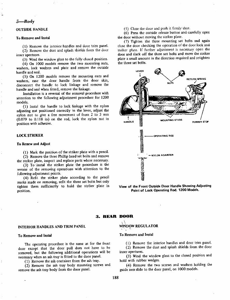
5 BodyOUTSIDE HANDLE
To Remove and Instal
I Remove the interior handles and door trim panel2 Remove the dust and splash shields from the door
inner apertures3 Wind the window glass to the fully closed position4 On 1000 models remove the two mounting nuts
washers lock washers and plate and remove the outside
handle and seal5 On 1200 models remove the mounting nuts and
washers ease the door handle from the door skin
disconnect the handle to lock linkage and remove the
handle and seal when fitted remove the linkageInstallation is a reversal of the removal procedure with
attention to the following adjustment procedure for 1200
modelsI Instal the handle to lock linkage with the nylon
adjusting nut positioned correctly in the lever adjust the
nylon nut to give a free movement of from 2 to 3 rom
0 079 to 0 18 in on the rod lock the nylon nut in
position with adhesive
LOCK STRIKER
To Renew and Adjust
I Mark the position of the striker plate with a pencil2 Remove the three Phillip head set bolts and remove
the striker plate inspect and replace parts where necessary
3 To instal the striker plate the procedure is the
reverse of the removing operations with attention to the
following adjustment points4 Refit the striker plate according to the pencil
marks made on removing refit the three set bolts but onlytighten them sufficiently to hold the striker plate in
position
5 Close the door and push it firmly shut
6 Press the outside release button and carefully open
the door without moving the striker plate7 Tighten the three mounting set bolts and again
close the door checking the operation of the door lock and
striker plate If further adjustment is necessary open the
door and slack off the three set bolts and move the striker
plate a small amount in the direction required and retightenthe three set bolts
@ GRETURN SPRING
NUTS
tHANDLE
MOUNTING STUDSRUBBER STOP
l OPERATING ROO
INYLON ADJUSTER
G
mI
View of the Front Outside Door Handle Showing AdjustingPoint of Lock Operating Rod 1200 Models
3 REAR DOOR
INTERIOR HANDLES AND TRIM PANEL
To Remove and Instal
The operating procedure is the same as for the front
door except that the door pull does not have to be
removed but the following additional operations will be
necessaty when an ash tray is fitted to the door panel
I Remove the ash container from the ash tray
2 Remove the ash tray body mounting screws and
remove the ash tray body from the door panel
WINDOW REGULATOR
To Remove and Instal
I Remove the interior handles and door trim panel2 Remove the dust and splash shields from the door
inner apertures3 Wind the window glass to the closed position and
hold with rubber wedges4 Remove the two screws and washers holding the
guide arm slide to the door panel on 1000 models
188

Door Lock Striker Early 1000 Model
5 Remove the screws holding the regulator to the
door panel and lower the regulator6 Slide the regulator arm 1200 models and the
guide arm 1000 models from their slides in the window
lift channel7 Lower the regulator to the bottom of the door and
wind the arm to the down position align the guide arm
with the regulator arm 1000 models and remove the
regulator out through the large aperture of the door panelboth models
Installation is a reversal of the removal procedure
NOTE Make sure the dust and splash shields are fittedco ectly over the door panel apertures before fitting the
trim panel
WINDOW GLASS
To Remove and Instal
1 Remove the interior handles and door trirn panel2 Remove the dust and splash shields from the door
inner apertures3 Remove the window regulator and let the glass rest
in the bottom of the door it will be necessary to remove
the window stop on 1200 models4 Remove the screws at the top of the division bar
and the screws holding the bottom of the division bar to
the door inner panel
Body6
Door Lock Striker Later Model 1000 and 1200 Models
JfrOUARTER WIN
I
TOP TRIM RETAINING CHANNEL
i
L Jj 11
i Do REGUL TOR
ISC SC WS
giif
IHAND
c J I T
AIN
1 QJ or INSERTDOOR LOCK
WlNDOW REGUl ArOR
o VISlDN EW1
JA
TRIMRETAINERINSeRTS rg
BOTTOM TRIM RETAINING CHANNEL
DIVISION 8AR
Rear Door with Trim Panel and Splash Shields Removed
4 Door 1000 Model
189
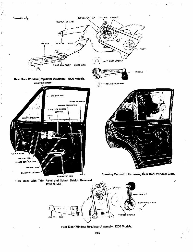
7 8ody
ROllER
Rear Door Window Regulator Assembly 1000 Model
MOUNTING SCREWS
REGULATOR ARM
C THRUST WASHER
c I HANDLE
y
It RETAININGSCREW
Showing Method of Removing Rear DoOr Window Glass
Rear Door with Trim Panel and Splash Shield RemovedM
f Ierz
jG i j
1 cTHRUST WASHER
OLLER ARM
RETAINING SCREW
Rear Door Window Regulator Assembly 1200 Model
190

BodB
5 Ease the division ar
and remove it from the door6 Remove the widow opening outer moulding7 Turn the window glass so hat the lift channel is
towards the qU lfter wiridow8 Raise the glass up through the door glass opening
and working from outside the door lif the glaSs clear of the
openingInstallation is a reversal of the removal procedure
After installing make sure the glass mov freely iq theslides without undue side movement A small amount of
adjustment is obtained by positioning he division bar
PLATE
@1
REMOTE CONTROL
REMOTE CONTROL lI K
rsJt
RETAI I G SCREW
THRUST WASHER
HANDLE
DOOR WCK AND REMOTE CONTROL0 Rear Door Lock A sembly Removed with loor Lock
Reversed to ShOw Detail Lock Barre and Lever Shownin In et 1000 rodelTo Remove and Instal 1000
I Remove the interior handles and door trim panels2 RelIlove the dust ine splash shields from the door
inner apef ures
3 Wind the jVinclow to the l sed position4 Remove the two screws 61dillg the remote control
to the door inner paneL5 Remove the door lock mo rmg crews
RETA N NG SCREW
Rear qoort
LockshoWin I ald Chi P oofLoc ingLevei LatelJOl O Model Door Lock Roller Early 1000 Model
1
191

@ RETURN SPRING
It NUTS
41
ll UFFER1 J 6 iCI
faIrr
LEVER MOUNTING STUDS
9 Body
6 Remove the lower division bar screws
7 Remove the remote control and door lock fromtheir mounted posi ions and slide them towards the frontedge of the door
8 Working through the door aperture disconnect thelock from the remote control rod and remove the lock andremote control from the door
Insianation is a reversal of the removal procedurePAWL
LOCKING ROD LOCKING EVER ETURN SPRING
Rear Dlr lock As emb y 1200 Model
Outside Door Handle for Rear Door 1200 Models
To Remove and Instal 1200
1 Remove the interior handles and door trim panel2 Remove the dust and splash shields from the door
inner apertures3 Wind the window to the closed position4 Remove the outside door handle retaining nuts and
washers and remove the door handle5 Remove the two screws holding the remote control
to the door inner panel6 Remove the snipper button7 Rellove he snipper rod and locking rod pivot
screw washer and nylon bush8 Remove the snipper rod from the door panel and
the rod retaining tapes9 Remove the door lock retaining screws and remove
the door lock through the apertureInstallation is a reversal of the removal procedure
OUTSIDE HANDLE
To Remove and Instal
I Remove the interior handles and door trim
2 Remove the dust jDd splash shields from the toprear door panel aperture
3 Remove the outside handle retaining nuts andwashers and remove the outside handle from the doorpanel
Installation is a reversal of the removal proceduretaking particular care that the outside handle weather seal isserviceable
To Remove
4 ENGINE BONNET
II
J Release the bonnet catch and open the bonnet2 Using a pencil Ilark around the outside edge of
each hinge plate3 Cover both fenders with a protective cover to
prevent damage to the paint work4 With the help of a second operator support the
bonnet and remove the bonnet stay from its guide5 Remove the mounting bolts holding the hinges to
the bonnet and remove the bonnet
To Instal
1 Holding the bonnet in the pOSItion previouslymarked fit the bonnet hinge bolts and tighten to Just over
fmger tight
192
P

2 Close the bonnet and by pushing with the hand
position the bonnet evenly in its opening3 Open the bonnet carefully and tighten the
mounting bolts
4 Recheck for correct positioning if necessaryloosen one bolt at a time to adjust
5 Check the bonnet catch when the catch is releasedthe bonnet should pop up sufficiently to enable the fingersto release the safety catch and lift the bonnet
6 To adjust first mark the base position with a
pencil then loosen the mounting bolts and move the catchin the desired girection tighten the bolts and rech ck
NOTE The male section of the catch will move sidewaysfor adjustment and the female section will move fore and
aftfor adjustment
7 Close the bonnet and check the locking position iftoo loose shorten the dove tail bolt if too tight lengthenthe dove tail bolt
8 To adjust the dove tail bolt loosen the lock nuta d Screw the bolt in or out using a screw driyer
Bodyl0
MALE SECTION OF C
TCHFIMOUNTING BO
t LOCK NurJ SAfPY CATCH Lr l li 1
Wf
1 j
ff
I
b
IOVE A 9lT0
To Remove
5 LUGGAGIl COMPARTMENT 1 10
Engine Bonnet Lock Components
I Open the lid with a pencil mark the edges of the
mounting plate to lid position on both sides2 Support the lid and remove the torsion bars3 While supporting the lid remove the two bolts from
each hinge plate and remove the lid
To Instal and Adjust
Installation is the reversal of the removal procedurewith the addition of the following pointsI Tighten the mounting bolts to just over finger tight
and close the lid check for even clearance around the lidand push into position with the hands
I
Boot Lid Striker Plate 1000 MOdels
t2 When the lid is correctly positioned carefully openand tighten the hinge bolts and recheck
3 To adjust the closed posiiion of the lid loosen thestriker plate screws and move the striker plate in the
required direction
NOTE The striker is adjustable sideways and up anddown
Boot Lid Lock 1000 VIOdels
193
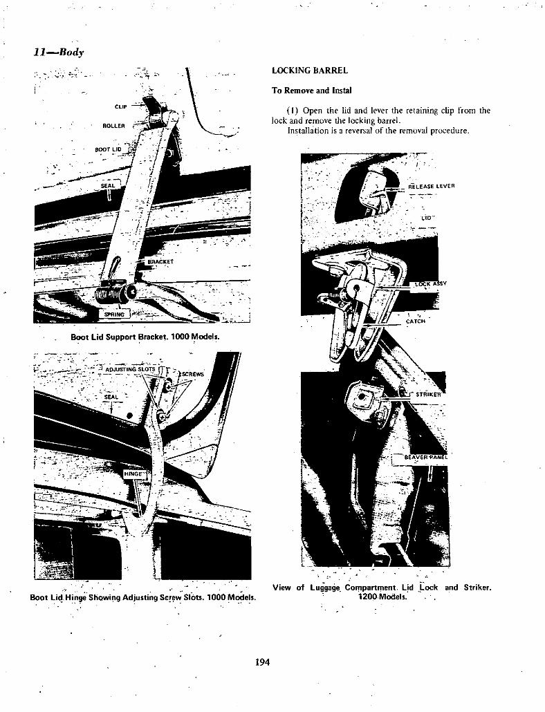
1l Body
r
Boot lid Support Bracket 1000 Model
7t
Boot liHingtl Showi g Adjusting SC wSlots 1000 Model
LOCKING BARREL
To Remove and Instal
I Open the lid and lever the retaining clip from theJock and remove me locking baIfel
In tallat on is a reversal of the removal procedure
A r
I
riD
View of luggage Compartment lid ock and Striker1200 MOdels
194

WHEELS AND TYRESSPIlCIFIATIOXS
1200 MODELS1000 MODELS
Wheel typeTyee size
Sedans
Pressed steel
550x 12
4 ply500 x 12
4 ply front6 ply rear
12 kg cm217 psi1 2 kg cm217 psiI 4 kg cm220 psi
Station sedan
Inflation pressures normal speedFront all models
Rear sedans
Rear station sedans
Wheel typeTyee size
Sedans and station wagons
Pressed steel
600x 12
4 ply
12 kg cm217 psi
Inflation pressures normal speedFront and rear
NOTE Increase the above pressures by 0 3 kg cm2 4 psifor sustainedhigh speed driving
TO REMOVE
I WHIlIlI NO TYIIIl 4SSIlMBI
1 Apply the handbrake
2 Detach the hub cap from the wheel to be removed3 Unscrew the wheel nuts approximately
three quarters of a turn4 Jack up the vehicle5 Remove the wheel nuts and withdraw the wheel
from the vehicle
TO INSTAL
Installation is a reversal of the removal procedure withattention to the following points
Tighten the wheel nuts in the order of 1 3 2 and 4 anddo notover tigbten
TO MAINTAIN
Proper tyre and whfel maintenance is essential foreconomical and safe operation
I Checkand adjust tyre pressures when the tyres are
in a cold condition Frequent loss of pressure should beinvestigated and the leakage rectified
NOTE Never adjust tyre pressures when the tyres are wann
otherwise pressures will be incorrect when the lyres cooldown
2 Inspect tyres regularly for damage and abnormalwear Any abnormal wear may be due to one or more ofthe faults shown in the illustrations or listed in the Fault
Diagnosis section Attention should e givel topenetrations or cuts in the tyre which will allow the entryof moisture into the carcass resulting in premature failure
3 Ensure that tyres are kept free of oil or grease4 Inspect the whee studs and nuts for thread damage
and the stud holes in the wheels for elongation5 Check the wheels for radial and lateral run out and
for damage to the flanges and bead seats6 Tighten wheel retaining nuts to the correct torque7 Periodically rotate wheels and tyresaccording to
the illustration sequence8 Maintain correct wheel balance
t
IDiagram for Correct Wheel Rotation to Prolong Tyre
Life and Minimise Tyre Wear
TO REMOVE
2 TUBIlD TVRES
I Jack up the vehicle and remove the wheel
2 Remove the valve cap and valve core
3 Separate the inside bead from the inside wheel
flange and using tyre levers with rounded edges lever thebead of the tyre over the inside edge of the flange
NOTE Exercise extreme care during operation 3 to
ensure that the levers do not damage the tube by forcing it
against the rim
195

2 Wheels and Tvres
4 Push the valve of the inner tube into the lyreinterior and withdraw the inner tube out between the inner
bead of the tyre and the inner flange of the wheel
Separate the outside beau of the tyre from the
outside flange at the wheel and using lyre levers with
rounded edges lever the bead of the tyre over the inside
flange of the wheel separating the two components
TO INSTAL
1 Remove any loose or excessive scale or rust from
the wheel flanges and finally clean with a wire brush or
emery paper2 Position the inside fiange of the wheel partially
inside one of the tyre beads and using tyre levers in goodcondition lever the remainder of the tyre bead over the
flange onto the wheel
NOTE During operation 2 ensure that the position of the
lyre bead opposite the side where the levers are applied is
seating in the Velbase of the wheel rim
3 Place the inner tube inside the tyre and insert the
valve through the hole in the wheelScrew a valve core removing tool on the end of the
valve to prevent the valve slipping back into the interior ofthe tyre when the other tyre bead is being placed on the
wheel4 Fit the second bead of the tyre over the wheel
inner flange using the tyre levers or a rubber mallet and
ensuring that the side of the bead adjacent to the tube valve
goes over the wheel flange last
NOTE in the event ofa tvre being marked with a balance
dot place the dot adjacent to the valve stem to maintain
correct tvre balance
5 Staod the wheel and tyre upright fit the valve core
and inflate the tube until the tyre beads commence to
position themselves on the wheel bead seats
6 Bounce the tyre on the floor several times to
position the tyre beads against the wheel flanges Inflate the
tyre and tube to the recommended pressure and finallycheck the valve core for leakage and instal the valve cap
TO TEST FOR LEAKS
I TUBEI IlSS T IlIlS
I With the wheel removed from the vehicle inflate
the tyre to the recommended pressure immerse the tyreand wheel in a water tank and check for leaks
2 Place the assembly in the tank so that the valve is
uppermost then submerge the valve and check for bubbles3 Release and allow the assembly to float ensuring
the channel between the rim flange and the tyre is filledwith water carefully check for air bubbles emitting from
this area
4 Turn the wheel assembly over and submerge the
wheel rivets if not already submerged and check for leaks5 Submerge the assembly and fill the channel
between the flange and the tyre allow to float and check
for leaks If leaking wipe area dry and mark the position of
the leak with chalk
TO REPAIR LEAKS
I Repair of a small fracture not exceeding 2 38 mm
0 093 in in the tyre may be repaired by applying sealingcement or dough with a suitable applicator
2 Minor repairs to the rim seat can be effected bydeflating the tyre and holding the bead away from the seat
and cleaning offthe affected area
3 To repair fractures not exceeding 635 mm 0 250
in in diameter remove the tyre from the wheel and repairthe fracture by inserting a rubber plug coated in cement
into the hole with the needle provided in the repair kit
Withdraw the needle after ensuring it has fully penetratedthe tyre and cut the rubber leaving approximately 6 35
mm 0 250 in protruding above the tread
NOTE Should the fracture he in excess of 6 35 mm 0 250
in tlte repair should be carried out by an aUlhorised tyre
dealer
4 If the valve stem is leaking deflate the tyre and
remove from th wheel Remove the valve from the wheel
and inspect for splitting crushing or dirt between the wheel
and the valve Clean area or replace if necessaryWhen fitting a new valve wet the valve stem and valve
hole with soap and insert from the inside of the wheel
Using Schrader tool No 553 pull the valve through until
correctly seated on rim Do not use pliers or similar hand
tools to fit valve
TO REMOVE
I Remove the wheel from the vehicle remove the
valve cap and core
2 Separate both inside and outside beads from thewheel flanges so that the beads are in the base of the rim
3 Using tyre levers with rounded edges lever thebeads of the tyre one at a time off the inner flange of the
wheelPrior to removal use a soap solution on the beads and
wheel flange and see that the beads diametrically oppositethe point of leverage are seating on the bottom of the
wellbase
TO INSTAL
1 Remove loose or excessive scale or rust from the
wheel taking care not to damage paint Repaint the wheel
if necessary
196

2 Remove any dents from the rim flanges and wipeclean with a moist rag
3 Clean off the tyre beads moisten tyre beads rim
surfaces and tyre levers with clean water or soap solution
4 Fit the tyre in the normal way use narrow leversand taking small bites to avoid strain and damage to thebeads Avoid damage at all limes as the sealing quality ofthe tyre is determined by the condition of the bead
5 Fit the second bead so that the part of the beadnearest the valve goes over the rim flange last
NOTE Do not use hammer or mallet to fit tubeless tvres
Ensure that the balance mark on the lyre is adjacent to the
valve
TO INFLATE
i Holding the assembly upright bounce the tread ofthe tyre on the ground at several points around its
periphery This will help to seat the beads on the taperedrim seats and provide a partial seal
Wheels and Tyres3
2 With the valve core removed connect the air hoseand inflate the tyre until the beads have sealed correctly It
may be necessary to bounce the tyre while inflating3 Remove the air hose fit the valve core and infiate
the tyre to 2 81 kg cm2 40 psi Test the tyre for leaks anddeflate to the normal pressure
TO INFLATE USING A TOURNIQUET
l Inflate the tyre with the assistance of a tourniquetuse Dunlop tool No TTl or its equivalent follow the
fitting instructions included in the kit2 With the valve core removed inflate the tyre until
the beads are sealed against the flanges Remove the hose
fit the valve core and inflate the tyre to 2 81 kg cm2 40
psi Test the tyre for leaks and defiate to normal pressure
NOTE A s an alternative methud a tourniquet can be madebv using a piece of rope and a suitable lever e g a bar tyrelever orapiece ofwood
Abnormal wear on both sides of tread
4 TynE WE R DI lOSIS
Pussible cause
a
b
Under inflation of tyresOver loading
Remedy
Check and inflate to recommended pressuresReduce maximum loading
2 Abnormal wear in centre of tread
Possible cause
a Over inflation oftyres
Remedy
Check and reduce to recommended pressures
197

4Wheel and Tyre3 Abnormal wear on inside of tyres
Possible cause Remedy
al Insufficient camber angleb Sagging front coil spring s
c Loose or worn front hub bearingsd Bent stub axle
e Loose or worn suspension arm components
Check front end alignment and adjust as necessaryCheck and renew faulty spring s
Check and adjust or renewhub bearingsCheck and renew faulty componentsCheck and renew faulty components Align front end
4 Abnormal wear on outside of tread
Possible cause Remedv
a Excessive camber angleb Incorrect coil spring s fitted
Check front end alignment and adjust as necessaryCheck and instal recommended replacement spring s
S Spotty or irregular wear
Possible cause Remedy
a Static or dynamic unbalance of wheel and tyreassembly
b Lateral run outof wheel
c Excessive play in wheel hub bearingd Excessive play in steering knuckle ball joints
Check and balance wheel and tyre assembly
Check and true up or renew wheelCheck and adjust or renewhub bearingCheck and renew ball joints
6 Lightly worn spots at centre of tread
Possible cause Remedy
a Static unbalance ofwheel and tyre assemblybl Radial runout eccentricity of wheel
Check and balance wheel and tyre assemblyCheck and renew wheel
7 Flat spots at centre of tread
Possible cause Remedy
a Eccentric brake drurn
b Repeatedly severe brake applicationc Lack of tyre rotation
Check and renew brake drum
Revise driving habits
Periodically change tyres by rotation of wheel tyreassembly
198

8 Heel and toe wear sawtooth effect
Possible cause Remedy
a Over loadingb High speed drivingc Excessive braking
9 Feathered edge on one side of tread pattern
Revise max um loadingAvoid as far as possibleRevise driving h bits
Possible cause Remedy
a Sharp inside edge excessive toe in
b One tyre sharp inside edge other tyre sharp outside
edge
Check and adjust wheel alignmentCheck for bent steering arm and renew
199

1000 SER ES
LBBRICATION AND MAINTENANCE1200 SERIES
ENGINE
Sump without filter
Sump with filter
Grade of lubricant
MANUAL TRANSM SSION
Capacity
Lubricant grade
AUTOMATIC TRANSMISSION
Capacity
Lubricant grade
REAR AXLE
Capacity
Lubricant grade
STEERING BOX
Capacity
Lubricant grade
COOLING SYSTEM
Without heater
With heater
FUEL TANK
Capacity Sedan
Capacity Station Wagon Van
ENG NE
3 04 litre Sump withou t fiIter 2 7 litre5352 Imp pt 4 760 Imp pt645 US pt 5 750 US pt
3 58 litre Sump with filter 3 24 litre6 125 Imp pt 5 750 Imp pI7 5 US pt 6 875 US pt
SAE 30 Grade of lubricant SAE 30
MANUAL TRANSM SSION
O R litre Capacity 12 litre15 Imp pb 2 25 Imp ptI 8 US pt 2 50 US ptSAE 90 HD Lubricant grade SAE 90 HD
AUTOMATIC TRANSMISSION
5 250 litre Capacity 5 5 litre9 125 Imp pt 9750 Imp pt
111 US pt II 750 US pt3N71 A Type F Lubricant grade 3N71A Type F
or equivalent or equivalent
REAR AXLE
0 710 litre Capacity 0 75 litre1250 Imp pt 1375 Imp pt15 US pt 1 625 US pt
SAE 90 HD Lubricant grade SAE 90 HD
STEERING BOX
0 240 litre Capacity 0 23 litre0 5 Imp pt 0375 Imp pt0 6 US pt 0 500 US pt
SAE 90 HD Lubricant grade SAE 90 ffD
COOLING SYSTEM
3 8 litre Without heater 4 2 litre6 750 Imp pt 7375 Imp pt
7 8 US pt 8 875 US pt45 litre With heater 4 9 litre8 Imp pt 9 625 Imp pt9 6 US pt 10378 US pt
FUEL TANK
35 litre Capaci ty Sedan 40 litre7 875 Imp gal 8 75 Imp gal918 Us gal 00 5 US gal
30 litre Capacity Coupe Station Wagon Van 38 litre
6 750 Imp gal 8375 Imp gal8 8 US gal Ip O US gal
200

CRANKCASE AND OIL FILTER
I ENGINE
L 1 rication and Uaifltenance2
1 Check oil daily and top up with specified gradewhen necessary
2 Drain and fill the sump at the first i 000 km 600miles again at 3000 km 2000 miles Continue to changeoil at every 3000 km 2000 iniles until the mileage readingis 10 000 km 6000 miles Subsequent changes every 5000km 3000 miles If vehicle is operating under dusty or
severe conditions change oil and filter more frequently3 Change the oil filter at 5000 km 3000 miles and
every 10 000 km 6000 miles during oil change oHverysix months
4 Clean the oil filler cap every 10 000 km 6000miles Wash in petrol dry out and ie oil
5 Clean crankcase ventilation control valve every20 000 km 12 000 miles
COOLING SYSTEM
1 Check coolant level in radiator daily and top upwith clean water vvhen necessary
2 Drain fiush and refill the cooling system withclean water every 10 000 km 16 000 km 6000 10 000miles
FUEL SYSTEM
I Clean the fuel pump filter every 10 000 km 6 000miles and check fuel pump operation every 20 000 km
12 000 miles
Change the fuel pump filter every 20 000 km 12 000miles
2 Remove air cleaner element every 5000 km 3 000miles and tap out dust Using low pressure air blowoutthe remainder of the dust Clean the air cleaner body and
fe instal elementThe air cleaner element should be changed every
40 000 km 24 000 miles or more frequently when
operating under dusty conditions Do not washer the paperelement in petrol or solvent of any kind
3 Lubricate accelerator Iinkag points with a fewdrops of engine oil every 10 000 km 6000 miles
4 Lubricate the carburettor linkage every 10 000 km
6000 miles with a few drops of engine oil
GEARBOX
2 TRANSMISSION
I Check the oil level and top up as necessary every5 000 km 3 000 miles with correct grade of lubricant
2 Drain and refill the gearbox when the vehicle has
completed 1000 km 600 miles and subsequently every40 000 km 24 000 iniles with the correct grade ofiubricant
PROPELLER SHAFT
I Repack the universal joints every 50 000 km30 000 miles with lithium based grease
2 Replce the universal joints when found to be
unserviceable
REAR AXLE
1 heck the oil level iri the rear axle and top up as
necessary every 5000 km 3000 miles with the correct
grade ofIubricant2 Drain and refill the rear axle when the vehicle has
completed 1000km 6000 miles and subsequently every50 000 km 30 000 miles with the correct grade of
lubricant
FRONT SUSPENSION
I SUSPENSION AND STEERING
I Remove clean and repack the hub bearings withwheel bearing grease every 50 000 km 30 000 miles orearlier if operating under severe conditions
STEERING
1 Steering box is filled on assembly and must not be
over filled2 Check for leaks and if excessive remove and
rectify refillwith correct amount and grade ofoil
3 Check oil level iri the steering box every 10 000 km6000 miles and top up with correct grade of oil when
necessary4 Clean the area surrounding the suspension ball
joint and grease every 20 000 km 12 000 miles5 Rehew the lubricant in the suspension ball joint
every 50 000 km 30 000 miles
6 Lubricate the steering linkage every 20 000 km
12 000 miles7 Renew the lubricant in the steering linkage every
50 000 km 30 000 miles
201

J bricaiion and Maintenanfe
BRAKE FLUID RESERVOIR
t lIsnIL OUS
BATTERY
I When disc brakes are fitted flush and change the
hydraulic brake fluid every 20 000 km 12 000 miles withclean heavy duty hydraulic brake fluid
ALTERNATOR
The alternator bearings are packed with grease duringassembly and no further lubricating is necessary duringoperatioQ
DISTRIBUTOR
I Remove ihe distributor cap and rotor and insert a
few drops of oii in the top of the distributor shaft earn
assembly to lubricate the earn bearing every 10 000 km6000 miles
2 Smear the distributor earn lobes with a highmelting point grease when the contact points have beenremoved for cleaning or renewal
Check and top lip electrolite with distilled water as
required or at least fortnightly
TYRES
I Test and inflate when cold to recommended
pressures as required or at least fortnightly2 Rotate tyres every 10 000 km 6000 miles
BODY
I Check and lubricate the following components
every 10 000 km 6000 miles with dry lubricantDoor locks and strikers bonnet catch luggage lock and
striker
2 Lubricate the following components with a few
drops of engine oil Door hinges luggage compartmentlock mechanism and hinges
Lubricate the hand brake linkages clutch and footbrake linkages and remote coritrollever
202

EMISSION CONTROLSPECIFIfATIONS
Ignition timingEngine idle speed
Manual transmission
Automatic transmission
5 deg btdc
700 rpm600 rpm in D
rangeDistributor
Make
Model
Capacitor capacityDwell anglePoint gap
HitachiD412 63
0 22 mfd49 55 deg0508 mm
0 020 in
NGKBP 6E
0 80 0 90 mm
0 031 0Q35 in
Spark plugMakeModel
Gap
AlternatorMake
Model
Capacity
Hitachi
LT133 0S
12 volt
33 ampCarburettor
Make
Model
Type
HitachiDCG306Dual throat
downdraft17 5 deg2 3
Fast idle setting at full choke
CO percentage setting
Flow guide valve
Make
Model
Opening pressure
Hitachi
FGA l
10mm hg0 4inhg
Control valve
Make
Model
Operating depression at sea
level manual transmission
Hitachi
TPA28 1
566
579 mm hg223
22 8 in hgServo diaphragm
Full stroke 5 0mm
0 197 in
1700 1800
engine rpm
Operating stroke no loading
To reduce Carbon Monoxide Hydrocarbons andOxides of Nitrogen which are the three primary automativeemissions causing air pollution three distinct types ofemission control systems are used in the BIIO SeriesDatsun range of vehicles
Depending on pollution standards involved the systemmay be found to be fitted collectively or separately to thevehicle
I fRANKt ASE V NTII ATION S HiTEM
The Closed System draws clean induction air fromwi thin the air cleaner assembly through a meshed flamearrester and into a hose which is connected to the rocker
cover
The air is then passed through the engine and into theinlet manifold via an oil separator hose and regulatingvalve Crankcase vapours are thereby fed back into the
cylinders and consumed
As with the sealed system the oil dipstick and filler capare sealed from the atmosphere
This system is most effective at part throttle operationwhere a pa ticularly high vacuum is present in the inletmanifold to allow the regulating valve to open and for allcrankcase vapours to be scavenged from the crankcase At
full throttle operation the manifold vacuum is insufficient
to draw all crankcase vapours through the regulating valveand into the inlet manifold Under these conditions the
crankcase ventilation flow is reversed with the fumes
drawing into the air cleaner instead of the inlet manifoldIf the engine is excessively worn and blow by is at a
high level then irrespective of throttle operation a certain
amount of crankcase vapour will re cycle back through the
rocker cover and into the air cleaner
DESCRIPTION
Two types of crankcase ventilation systems are used as
standard equipment on the 8110 series engines One isknown as the sealed system and the other as the closed
systemThe sealed system was used on some earlier type
vehicles but was replaced by the closed system which isnow standard equipment on all models which are exportedto the USA and Canada
The Sealed System consists of a hose connecting therocker cover to the air cleaner assembly Pressure dropcreated within the air cleaner assembly by air flow permitscrankcase vapours to flow from the crankcase via the rockercover into the air cleaner assembly where they are drawninto the inlet manifold and consumed in the cylinders
The engine oil dipstick and also the oil filler cap are
sealed to prevent crankcase fumes from escaping into theatmosphere
To prevent air cleaner element oil contamination
through crankcase vapour the hose inlet connection intothe air cleaner assembly is so situated that the vapourentering the assembly does not pass through the element
203

2 Emission Control
FLAME TRAP
IHOSEAIRCLEANER TO VALveCOVER
HOSE PC v
VALVE TO CRANKCASE
DISPOSABLE PCV
QttOSE CLIPS
PCV VAlV
VALVE
IAIR CLEANER BASE
OIL FILLER CAP 9d
DIPSTICK
l
Components of Closed Type Ventilation SystemNote inset PCV Valve Disposable Type
A baftle plate and a meshed lIIter which is locatedwithin the crankcase prevents engine oil from being drawn
upwards into the inlet manifold
TO CHECK AND TEST OPERAliON
Sealed Svstem As this system is relatively simple anddoes not incorporate a regulating valve it is only a matter of
periodically checking the following components at the
recommended intervals of 12 months or 18 000 kilornetres
12 000 miles
I Check the rocker cover to air cleaner assemblyhose for collapsing blocking or deterioration Renew the
hose if after checking it is found to be unserviceable2 Check the seals on the engine oil filler cap and the
dipstick Renew the seals if they are damaged or if their
sealing qualities are suspectClosed System The system should also be serviced at
the recommended intervals of 12 months or 18 000kilomctres 12 000 miles with particular attention given to
the regulating valve
I Check the condition of the rocker cover to air
cleaner assembly hose and also the crankcase to inletmanifold hose Carefully check for blocking collapsing or
deterioration Renew the hoses as found necessary2 Check the seals on the engine oil filler cap and the
QO RING
dipstiCk Renew the seals if they are damaged or if their
sealing qualities are suspect3 Check the operation of the ventilation regulating
valve as followsWith the engine running at a steady idle speed
disconnect the hose from the regulating valveA sharp hissing noise will be heard at the valve when
the hose is disconnectedNow place a finger over the valve inlet A strong
vacuum should immediately be felt as the finger is placedover the valve
If the regulating valve is found to be partially or fullyinoperative then renew the valve as a complete assembly It
is not practicable to dismantle and clean the valve
4 A faulty regulating valve may give rise to anyoneor more of the following conditions
a Black smoke emerging from the exhaustb Engine hunting at idle
c Engine idle fluctuates but engine does not stalld Loss of power and surging at speeds above idlee Engine stalls after stops and runs roughly after
being restarted with indications ofa lean mixture
Note To ensure effident operation of the ventilation
system if is adl isahle to renew he regulating vah e everv
50000 kilomerres 30 OliO miles
2 XH liST O TII I S STE
Moditications to the distributor carburettor and the
introduction of a throttle opening device were used to
achieve this resultIt is known that when a coasting condition exists and
the throttle valve is fully closed an inadequate fuel air
DESCRIPTION
The engine modifications system is utilized to reducethe percentage of pollutant gases being expelled from the
engine exhaust
204

mixture is drawn into the engine where it is incompletelyburnt resulting in excessive carbon monox de and
hydrocarbon exhaust emissionThe throttle opening device is designed to open the
carburettor throttle valve whenever these coastingconditions exist This allows an adequate fuel air mixture tobe drawn into the engine where proper combustion takes
place therefore reducing the level of hydrocarbon and
carbon monoxide emission
The basic components of the throttle opening deviceare
Control Valve Servo diaphragm Interconnectingtubes
When deceleration takes place and inlet manifoldvacuum increases the control valve opens permittingmanifold vacuum to be routed to the servo diaphragmvacuum chamber As shown in the diagram the servo
diaphragm assembly is mounted on the carburettor and isconnected to the throttle lever through Iinkage Appliedvacuum actuates the servo diaphragm and linkage to the
carburettor thus slightly opening the throttle valve to thedesired degree
As manifold vacuum lowers to a predetermined leveldue to the vehicle speed decreasing the con trol valve beginsto close The control valve closing aBows the inlet manifold
vacuum to be maintained at the constant predeterminedlevel
An altitude corrector is built into the control valve
body and is adjusted to a slight preload to compensate forany variation in atmospheric pressure
This system does not effect engine braking which is
normally desired during deceleration
CONTROL VALVE
To Remove
I Raise the engine bonnet2 Disconnect the inlet manifold to control valve
vacuum tube3 Disconnect the control valve to servo diaphragm
vacuum tube
4 Loosen and remove the two control valve assemblyattaching bolts at the inlet manifold
5 The control valve assembly can now be removedfrom the engine compartment
NOTE It is not practicable to di mantle and repair the
control valve If the unit is malfunctioning then renew thevalve as an aHembly
To Instal
I Position the control valve back in the enginecompartment on the inlet manifold
2 Instal and tighten the control valve assemblyattaching screws
Emission Control B
3 Connect the inlet manifold to control valvevacuum tube
4 Connect the control valve to servo diaphragmvacuum tube
5 Check the operation of the valve and adjust if
necessary as described in a following section
SERVO DIAPHRAGM
To Remove
1 Detach the vacuum hose from the servo diaphragmvacuum chamber connection
2 Remove the carburettor from the engine as
previously described in the Fuel Section3 With the carburettor removed from the vehicle and
placed on a work bench withdraw the split pin and
disconnect the servo diaphragm link from the carburettorthrottle lever
4 Loosen and remove the locknut and detach theservo diaphragm from the moun ting bracket on the
carburettor
NOTE It is notpractical to dismantle and repair the servo
assemblv If the unit is malfunctioning then renew the servo
diaphragm assembll
To Instal
1 Position the servo diaphragm on the carburettorbracket and instal and tighten the locknut
2 Connect the servo diaphragm Iink to thecarburettor throttle lever and retain with a new split pin
3 Instal the carburettor to the engine as described inthe Fuel Section
4 Attach the vacuum hose to the servo diaphragmvacuum chamber connection
5 Check the servo diaphragm for correct operationand adjust if necessary See following text for correct
procedure
TO ADJUST SERVO DIAPHRAGMAND CONTROL VALVE
NOTE Make all checks and adjustments after first bringingthe engine to operating temperature Ensure that the chokevalve is in the fullv open position
I Connect a tachometer to the engine distributor2 Disconnect the servo vacuum pipe at the control
valve
3 Disconnect the control valve vacuum pipe at the
inlet manifold4 Now connect the servo diaphragm vacuum pipe
straight to the inlet manifold by passing the control valve5 Start the engine and without working the throttle
note the engine rpm reading on the tachometer scale
205

4EmiJJ ion Control
NOTE As soon as the engine is started inlet manifoldvacuum should actuate the seroo diaphragm and pull the
diaphragm link upwards until the link stop abuts the servo
body
6 If the servo diaphragm adjustment is correct the
engine speed should read between 1700 and 1800 rpm7 If the engine speed is below the lowest figure
quoted then back off the lock nut and turn the adjustingscrew clockwise slightly until the engine speed falls within
the figures quoted8 When the engine speed is above the highest figure
quoted back off the locknut and turn the adjusting screw in
an anti clockwise direction until the correct engine speed is
obtained9 Retighten the locknut after adjusting as described
in operation 7 or 8 whichever was applicable makingsure that the adjusting screw is not disturbed
NOTE See diagram for situation of adjusting screw andlocknut
10 Start the engine and disconnect the servo vacuum
hose from the inlet manifold and reconnect back to the
control valve Reconnect the control valve vacuum pipeback to the inlet manifold The control valve and servo
diaphragm vacuum piping should now be back in its originalposition
II Restart the engine and by actuating the
carburettor throttle lever by hand bring the engine up to
3000 rpm12 Release the throttle lever and let the engine speed
decrease of its own accord3 The engine speed should decrease from 3000 rpm
to 1000 rpm in 3 5 to 45 seconds for manual transmission
equipped vehicles and 2 5 to 3 5 seconds for automatic
transmission equipped vehicles
14 If the engine speed decrease tUnes are not within
the limits specified for respective applicable model thenloosen the control valve lock screw and turn the vacuum
adjusting screw slightly until the engine speed decrease time
falls within the lime figures as quoted in operation 13See diagram for control valve lock screw and adjusting
screw situation
NOTE Turn the adjusting screw in a clockwisedirection to
lengthen the engine speed decrease time and an
anti clockwise direction to shorten the engine speeddecrease time
IS When satisfied the adjustment is correct tightenthe control valve lock screw and recheck the engine speedadjustment to ensure that the vacuum adjusting screw hasnot altered position
CARBURETfOR
To obtain effective exhaust emission control it is
important that the carburettor idle speed and mixture
setting are periodically checked and accurately adjustedThe choke setting should be checked and adjusted to
affecting the tinal result regarding exhaust emission control
To Adjust Idle Speed and Mixture
I Connect a tachometer to the engine distributor2 Start and run the engine until it reaches normal
operating temperature3 Allow the engine to operate for one minute at
idling speed4 Adjust the throttle adjusting screw and the idle
mixture screw in conjunction with each other until a
smooth idle speed of 750 rpm is obtained 780 rpm forautomatic transmission
5 Now turn the idle mixture screw clockwise to
reduce the engine speed to 700 rpm 750 rpm forautomatic transmission
6 For vehicles that are fitted with automatic
transmission the idle speed should be 600 rpm when theshift lever is moved to the D position This can be checkedafter operation 5 and any subsequent slight adjustmentmade
IMPORTANT Ex treme care should be exercised when
carrying out adjustment with the transmission in the drivepas tion
7 Stop the engine and disconnect the tachometer
ELECTRICAL EQUIPMENT
To ensure efficient burning of the fuel in the enginecombustion chamber it is important that all electrical
equipment be periodically checked for serviceability as a
fault in anyone piece of electrical equipment usually has
adverse effects on other related components as well as
affecting the final result regarding exhaust emission control
Spark plugs
Remove and sand blast the plugs at the recommended
checking intervals Check each plug thoroughly for
cracking chipping and for excessive wear at the electrodesRenew the plugs as found necessary
If the spark plugs are still serviceable file the centre
electrodes flat prior to setting gaps with the correct
adjusting tool See Specifications section for correct
electrode gap
High Tension Leads
Remove the distributor cap with high tension leads
from the engine assembly
206

CARBURETTOR
SKONDAllYV
NrrPRIMARYVENTURI
INlET MANIfOLD
Using an ohmmeter check the resistance in each hightension l ad
Tq make the test fit a plug adaptor into the spark plugend of the lead and connect the ohmmeter between the
adaptor and the corresponding terminal in the distributorcap
If the resistance in any lead is more than 30 000 ohmscarefully remove the lead from the cap and check thele dresistance separately
If resistance is still over 30 000 ohms then renew theleads ai fault
iMPORTANT Carbon filled high tension leads must behandled carefullv at ail times Mishandling of leads willcause a breakdown in lead continuity
Distributor
The distributor breaker points should be checked at therecommended mileage iJitervals and renewed if abnormaJpitting and wear is evident
Ensure that the points are in correct alignment so thata full contact will be made when the points are in theclosed position
Emission COlltrol 5
MoUNTINGBRACKET
VACUUMADJUSTING
SCRTW
Throttle Opener Control System Arrangement
Set the gap and dwell angle to specificaiions in thenormal mariner and then check and adjust the ignitioniirning as follows
1 Check the spark plugs for serviceability and correct
gap2 Instal an ignition timing light and a tachometer to
the engine3 J Wipe the crankshaft pulley so that the iimihg
marks are clearly visible4 Warm up the engine and set the idling speed to 100
rpm5 Loosen the distributor reiaining screw far enough
to allow ihe distributor to be moved by hand
6 With ihe aid of the ii ing light adjust the ignitioniiniing to 5 deg btdc
NOTE The 5 deg mark on the crank shaft pulley is the firstgraduation on the right side of the tdc mark
7 Tighten the distributor set screw when ihe ignitiontiming is correctly adjusted but make sure that the timing isnot altered by moving the disiributor
8 Set the idie speed and mixture as previouslydescriOed
t EVAI OIlATn ll t OXTIlOI S STIM
Positive sealed fuel tank Vapour liquid separatorVapour vent Une Flow guide valveWhen the engine is at rest fuel vapour through
evaporation gradually fills the air space in the fuel tank
vapour liquid separator and apotir vent lines and as thefuel tank is fitted with a positive type sealing cap vapour
pressure builds up within the systemThe flow guide valve opens wtten the vapqur pressure
within the sysiem exceeds 10 mm hg 04 in hgJ Excess
DESCRIPTION
The evaporative control system is another approach in
reducing the amount of vehicle hydro carbon emission Ithas been estimated that approximately 20 percent of all
automotive hydrocarbon eniissi9n results from evaporativeloss from the fuel tank
The basic components of the evaporative controlsystem are
207

t FLAME TRAP
J lINLET MANIFOLD i
t GAS TIGHT
u
j TAr
il VAPOUR LIQUID SEPARATOR
I
FROM CRANKCASE
P
Emis ion CoJltrol
vapour is then by passed into the crankcase via a connectinghose
When the engine starts Vacuum created within the
inlet manifold opens the positive crankcase ventilation valveand also the crankcase side of the flow guide valve Vapourwhich has been stored in the crankcase vent line separatorand fuel tank is then drawn into the inlet manifold andconsumed in the cylinders
When vapour pressure within the system dropssufficiently the air cleaner side of the flow guide valve
opens This permits atmospheric air pressure to be routedfrom the air cleaner assembly to the fuel tank A flamearrester is situated in the line between the air cleaner and
the flow guide valve in case of backfire through thecarhurettor
Allowing air into the system prevents a high vacuum
forming within the system which could cause technicaldifficulties including a crushed fuel tank
FLOW GUIDE VALVE
The flow guide valve s most import ant function is to
prevent crankcase blow by from entering the vapour vent
line and fuel tank The valve should be removed and
checked for serviceability at the recommended intervals It
is not practicable to repair the valve if it is found to be
unserviceable
For easy identification the valve apertures are clearlyengraved with A F and C denoting Air Cleaner FuelTank Crankcase
FROM AIR CLEANER
J
FROM VALVE COVERAIR CLEANER
I
FLOW GUIDE
VALVE
iT
TO INLET MANIFOLD OR CRANKCASE
TO TEST
I Raise the engine bonnet2 Disconnect all hoses and then remove the now
wide valve from the vehicle3 Apply a low pressure of air to the fuel tank F
side aperture of the valve The air shuuld flow through the
valve and out the crankcase C side aperture4 If no air pressure is felt at the crankcase C
aperture then renew the valve5 Now apply air pressure to the crankcase C side of
the valve Renew the valve if air flow is felt from the air
cleaner A and fuel tank F apertures6 When air pressure is applied to the air cleaner A
aperture it is nonnal for air pressure to be felt at the
crankcase C and fuel tank F sides of the valve
FUEL TANK VAPOUR LIQUIDSEPARATOR AND
VAPOUR VENT LINE
To Test
I Check the fuel tank filler cap and all hoses for
serviceability2 Disconnect the vapour vent line from the flow
guide valve F aperture3 Connect a tee piece with manometer and a suitable
cock into the vapour vent line
4 Slowly apply air pressure to the system via thecock until the manometer indicates 14 5 in Aq then closethe cock
5 Leave the system undisturbed for 25 minutes and
then measure the height ofthe liquid in the manometer
6 The variation of height in the test instrument
should remain wi th 1 0 in Aq
7
FUEL TANk
PCV VALVE
Diagram showing Evaporation Control Systemwith Engine at Slow Running Speed
208

7 If the test is satisfactory remove the tank filler capand check that the fluid in the manometer drops quickly to
zero
8 If the fluid height in the manometer drops off
slowly a blocked vapour vent line is indicated The
Emission Control 7
blockage must be rectified to ensure sufficient vapour
delivery to the crankcase9 If the test instrument reading was unsatisfactory in
operation 6 check the tank filler cap and hoses for
leakage Rectify as found necessary
4 EXHAUST CONTROl S STFM FAIJLT IUAt NOSIS
Engine knock when coasting
Possible cause
a Incorrectly adjusted throttle openerb Malfunctioning control valve
2 Erratic engine idle
Possible cause
a Incorrect ignition timingb Incorrect carburettor adjustment
3 Engine idling too fast
Possible cause
a Incorrectly adjusted throttle openerb Malfunctioning throttle cable or linkagec 1 Malfun tioning control valve
4 Engine stops
Possiblecause
a Incorr ctcafburettor adjustmentb Incorrect ignition timing
Remedv
Adjust throttle openerRenew control valve
Remedy
Reset ignition timingAdjust carburettor
Remedy
Adjust throttle openerCheck throttie cable or linkage and rectifyRenew control valve
Remedy
Adjust carburettorReset ignition timing
RIlCO MIlNDIlD I INTFNANCt
To ensure efficient operation of the emission controlsystem it is important that the following service procedurebe carried out on the items mentioned at the recommcndeu
mileage intervals
ENGINE
I Carry out the following service procedure every
5000 km 3000 milesCheck distributor points for serviceability and adjust
dwell angleCheck and adjust ignition limingCheck and adjust engine idle speed and mixture
Remove clean and regap spark plugs2 Carry out the following service procedure every
10 000 km 6000 miles
Sparingly lubricate distributor cam and cam heel
3 Carry out the following service procedure every
20 000 km 12 000 milesRenew distributor contact pointsRenew spark plugsCheck high tension leads for serviceabilityTune and test engine4 Carry out the following service procedure every
40 000 km 24 000 milesRenew carburettor air cleaner element
CRANKCASE VENTILATlON SYSTEM
1 Carry out the following service procedure every
20 000 km 12 000 miles
Check for correct operation of crankcase regulatingvalve
Check all hoses and connection for leaks
209

8 Emiuion Control
EXHAUST CONTROL SYSTEM
I Carry out the following service procedure every20 000 km 12 000 miles
Check and adjust control valve and servo diaphragm
EVAPORATIVE CONTROL SYSTEM
I Carry out the following service procedure every20 000 km 12 000 miles
Check hoses pipes and connections for leakageRemove and test flow guide valve for correct operation
210

INDEXENGINE To Service Top Cover 37
Specifications 7 To Service Flange 38
Description 9 To Assemble 38
Engine and Transmission 10 To Check and Adjust Float Level 39
To Remove and Instal 10 Choke Interlock Adjustment 40
Rocker Arms and Shaft 11 Primary and Secondary ThrottleTo Remove and Dismantle II Interlock Adjustment 40To Assemble and Instal 11 To Adjust Idling Speed and Mixture 41
Cylinder Head 12 Fuel Pump 42
To Remove 12 Description 42
To Dismantle 12 To Remove and Instal 42
To Check and Inspect 13 To Dismantle 43
To Renew Valve Guides 13 To Clean and Check 43
To Check Valve Spring 13 To Assemble 44
To Assemble 14 Fuel Pump Capacity Test 44
To Assemble 14 Air Cleaner 45To Adjust Valve Clearance 14 Description 45
Engine Sump IS To Remove 45
To Remove and Instal 15 Fuel System Fault Diagnosis 45
Timing Chain and Cover 15 To Instal 45To Remove 15
To Instal 15 CLUTCH
Camshaft and Tappets 16 Specifications 47
To Remove 16 Description 47
To Instal 18 Clutch Unit 48
Pistons and Connecting Rods 18 To Check and Inspect 49
To Remove and Dismantle 18 Master Cylinder 49
To Fit New Piston Rings 19 To Remove and Instal 49
To Reassemble and Instal 19 To Dismantle 50
Cylinder Bores and Pistons 20 To Clean and Inspect SOTo Check Cylinder Bores 20 To Assemble SO
Deglazing Cylinder Bores 20 Slave Cylinder 50
Checking Piston Skirt Clearance 21 To Remove and Dismantle SO
Crankshaft and Main Bearings 21 To Clean and Inspect 51
To Remove and Instal 21 To Assemble and Instal 51
Oil Pump and Filter 23 Hydraulic System 51
To Remove and Instal 23 To Bleed 51
To Dismantle and Assemble 23 Outch Throw out Bearing 52
Engine Mountings 25 Mechanically Operated Clutch to
To Remove and Instal Front 25 Renew 1000 Series 52To Remove and Instal Rear 25 Mechanically Operated Clutch to
Engine Fault Diagnosis 25 Renew 1200 Series 52
Hydraulic Clutch to Renew
COOLING SYSTEM 1200 Series 53
Specifications 28 Clutch Pedal 54
Description 28 Hydraulic Clutch 54
Radiator 28 To Remove and Instal 54
To Remove 28 Pedal and Control Cable 54
To Check 28 To Remove and Instal 1000 Series 54
To Instal 29 Pedal and Control Cable 54
Thermostat 29 To Remove and Instal 1200 Series 54
To Remove and Instal 29 Adjustments 55
To Check 29 Hydraulic Clutch 55To Adjust Pedal Height 55
FUEL SYSTEM Hydraulic Clutch 55
Specifications 34 To Adjust Withdrawal Lever
Carburettor 35 Free Travel 55
To Remove and Instal 35 Pedal and Control Cable 55
To Service 35 To Adjust 1000 Series 55
To Dismantle 36 Pedal and Control Cable 55
To Clean Parts 37 To Adjust 1200 Series 55
To Service Main Body 17 Clutch Fault Diagnosis 56
211

2 lndex
MANUAL TRANSMISSION To Assemble and AdjustSpecifications 57 Differential 91Part I Three Speed Transmission Axle Shaft and Bearings 93
Gearbox 57 To Remove 93Description 57 To Renew Axle Shaft Bearings 93To Remove and Instal 58 To Instal 93To Dismantle 58 Rear Axle Assembly 94To Clean and Inspect 60 To Remove and Instal 94To Assemble 60 Part 2 Rear Axle 1200 cc Models 94Gear Change Assemble 63 Description 94To Remove and Instal 63Part 2 Four Speed Transmission DIFFERENTIAL CARRIER ASSEMBLY
Gearbox 64 To Remove and Instal 94Description 64 To Dismantle 94To Dismantle and Assemble 64 To Clean and Inspect 96To Adjust Gear Change Rods 64 To Assemble and Adjust DriveTo Remove and Instal 65 Pinion 96To Dismantle 65 To Adjust Pinion Bearing Pre Load 98To Clean and Inspect 68 To Assemble and Adjust Differential 98To Assemble 68 Drive Pinion Oil Seal 99Part 3 Propeller Shaft 70 To Renew Oil Seal and or Pinion Flange 99Description 70 Axle Shaft and Bearing 101To Remove and Instal 71 To Remove 101To Dismantle and Assemble 71 To Renew Axle Shaft Bearing 101Part 4 Manual Transmission Fault To Instal 101
Diagnosis 71 Rear Axle Assembly 101To Remove and Instal 101Rear Axle Fault Diagnosis 102
AUTOMATIC TRANSMISSIONSSpecifications 73 STEERINGDescription 73 Specifications 103Engine Tuning 74 Description 103Towing 74 Steering Gear Assembly 103Hydraulic Fluid 74 To Dismantle 104To Check and Top Up 74 To Clean and Inspect 104To Drain and Fill 76 To Assemble 104Transmission Selector Linkage 76 Collapsible Steering 106To Adjust 76 Description 106Neutral Safety Switch 76 Jacket Tube 106To Adjust 76 To Remove and Inspect 106Kickdown Switch and Downshift
Cohujm Clamp 107Solenoid 78 Inspect and Instal lO7To Check and Test 78
Steering Linkage 107Stall Test 79 To Remove and Dismantle 107Line Pressure Test 80 To Assemble and Instal 107To Check and Test 80 To Assemble and Instal 108Transmission Assembly 81 Idler Arm 108To Remove 81 To Remove and Dismantle 108To Instal 82 To Assemble and Instal 108Automatic Transmission Fault Linkage Adjustment 108Diagnosis 82 To Adjust Steering Lock Stops 108To Check and Adjust Toe in 109REAR AXLESteering Fault Diagnosis 110Specifications 85
Part I Rear Axle 1000 Models 86
Description 86 FRONT SUSPENSIONDifferential Carrier Assembly 86 Part I 1000 SeriesTo Remove and Instal 86 Specifications IIITo Dismantle 87 Spring and Lower Control Arm IIITo Clean and Inspect 88 To Remove and Inspect IIITo Assemble and Adjust Drive To Instal 112
Pinion 88 Upper Control Arm 113To Adjust Pinion Bearing 91 To Remove and Inspect 113
212

To InstalStub Axle SwivelTo Remove and InspectTo Check and Adjust Castor and Chamber AnglesTo Instal
Shock AbsorbersTo Remove and InstalTo Test and BleedBall JointsTo Remove and InstalFront Suspension Fault Diagnosis 1000 SeriesPart 1200 SeriesSpecificationsDescriptionWheel Hub and BearingsTo Remove and Dismantle
Drum Type BrakesTo Clean and InspectTo Assemble and InstalTo Remove Disc Type Brakes
To Clean and InspectTo Assemble and InstalStabiliser BarTo RemoveTo InstalRadius RodTo Remove
To Instal
Suspension UnitTo RemoveTo Clean and DismantleTo Clean and InspectTo AssembleTo Instal
Suspension Control ArmTo RemoveTo InspectTo InstalLower Ball Joint
To Remove
To Clean and InspectTo InstalSuspension AssemblyTo Remove
To Clean and InspectTo InstalSusp nsion and Steering AnglesAdjustmentsTo Check and Adjust Toe InTo Check Camber and CasterFront Suspension Fault Diagnosis
REAR SUSPENSION
Specifica lions
DescriptionShock AbsorbersTo Remove and InstalTo Test and BleedSpringsTo Remove and DismantleTo Assemble and Instal
Suspension Fault Diagnosis
1141141141141141 IS115115115115
115117117117118
BRAKES
SpecificationsDescriptionDrum BrakesDisc BrakesSingle Circuit Master CylinderTo Remove and InstalTo DismantleTo Clean and InspectTo AssembleDual Circuit Master CylinderTo Remove and InstalTo Dismantle NabcoTo Dismantle TokicoTo Clean and Inspect Nabco and TokicoTo Assemble Nab co
To Assemble TokicoRear Brake AssemblyTo Remove and DismantleTo Clean and InspectTo Assemble and InstalFront Wheel Drum BrakesTo Remove and DismantleTo Clean and InspectTo Assemble and InstalFront Wheel Disc BrakesTo Remove and Instal Brake CaliperTo Dismantle and AssembleTo Remove and Instal Brake DiscsRear Brake Backing PlateTo Remove and InstalFront Brake Backing Plate
To Remove and Instal Drum BrakesHandbrake AssemblyHandbrake Lever Assembly and Front
Cable to Remove and Instal 1000To Remove and Instal 1200Rear Handbrake Cable To Remove 1000To Remove 1200To Inspect Both ModelsTo nstal Both ModelsBrake AdjustmentTo Adjust Front Brake Shoes
Drum TypeTo Adjust Rear Brake Shoes All ModelsTo Adjust Handbrake Cable 1000
To Adjust Handbrake Cable 1200Brake Pedal Height Adjustment 1000Brake Pedal Height Adjustment 1200Hydraulic SystemTo BleedBrake Fault Diagnosis
118118118118119119
119119119119
119120120120120
121121122122
122122122122
122123123123
23In123123
123123124124
127127128128
128128
128128129
ELECTRICAL SYSTEMSpecificationsBatteryMaintenance
AlternatorDescriptionTo Remove and InstalService PrecautionsTo Remove and Instal
213
Index fJ
130131131131
131131132132132132133133133
134134134135135136136
138138138139
140140140141141
141142142143
143143144
144144144145
145145145145145
145146146147
148151151
151151151152
152

4lndex
To Test the Alternator 152 licence Plate Lamp 176To Test on the Vehicle 152 Electrical Fault Diagnosis 178To Dismantle 153To Clean Parts 154 BODYTo Check and Test Components Parts 154 Windscreen and Rear Window 184To Assemble 156 Windscreen 184Alternator Regulator 157 Front Door 184Qescription 157 Interior Handles and Trim Panel 184Regulator Adjustments 157 Rear Window Glass 184To Remove and Instal 158 Window Regulator 185Mechanical Adjustments 158 Window Glass 186Electrical Adjustments 159 Door Lock and Remote Control 186Starter Motor 161 Outside Handle 188Description 161 Lock Striker 188ToTest on the Vehicle 161 Rear Door 188To Remove and Instal 162 Interior Handles and Trim Panel 188To Dismantle 162 Window Regulator 188To Check and Inspect 162 Window Glass 189To Assemble 163 Door Lock and Remote Control 191Test and Adjust 164 OutJide Handle 192Distributor 165 Engine Bonnet 192Description 165 Luggage Cumpartment lid 193To Clean and Adjust Breaker Points 165 To Remove 193To Remove 166 To Instal and Adjust 193To Dismantle 166 Locking Barrel 194To Clean and Inspect 167 To Remove and Instal 194To Assemble 167To Instal 168 WHEELS AND TYRESTo Time Engine and Set Ignition Timing 169 Specifications 195To Adjust Ignition Timing and Dwell Angle 169 Wheel and Tyre Assembly 195
Sparking Plugs 170 To Remove 195To Service 170 To Instal 195
High Tensiun Leads 170 To Maintain 195Ignition Coil 170 Tubed Tyres 195Turn Signal Switch Headlight Dipper To Remove 195
and Horn Button 170 To Instal 196Description 170 Tubeless Tyres 196Horn Button 170 To Test for Leaks 196Turn Signal Switch 172 To Repair Leaks 196Switches and Controls 173 To Remove 196Headlamp Switch 173 To Instal 196Windscreen Wiper Switch 173 To Inflate 197Ignition Switch 173 To Inflate Using a Tourniquet 197Inhibitor Switch 173 Tyre Wear Diagnosis 197Stop Light Switch 173Handbrake Warning light 173 LUBRlCAnON AND MAINTENANCEDual Brake System Waming light Switch 173 Engine 201
Cigarette Lighter 174 Cooling System 201Choke Control 174 Fuel System 201
Heater Controls 1000 174 Transmission 201Heater Controls 1200 174 Gear Box 201Instrument Cluster 174 Propeller Shaft 201
To Remove and Instal 1000 174 Rear Axle 201
To Remove and Instal 1200 175 Suspension and Steering 201Windscreen Wiper 175 Front Suspension 201To Remove and Instal 175 Steering 201To Remove and Instal the Pivot Boxes 175 Miscellaneous 202
Lamp Units 175 Brake Fluid Reservoir 202To Remove and Instal Headlamp Unit 175 Alternator 202To Adjust Headlamps 176 Distributor 202To Remove and Instal Front Turn Battery 202
Signal and Park Lamp 176 Tyres 202Rear Combination Lamp 176 Body 202
214

EMISSioN CONTROL SYSTEMSpecificationsCrankcase Ventilation SystemTo Gheck and Test OperationExhaust Control SystemControl ValveServo DiaphiagmTo Adjust Servo Diaphragm and Control ValveCarburettorTo Adjust Idle Speed and MixtureElectrical EquipmentSpark PlugsHigh Tension LeadsDistributor
Evaporative Control SystemDe criptionFlow Guide Valve
203203204204205
205205206206206206206
207207207208
To TestFuel Tank Vapour Liquid Separator and
Vapour Vent Line
Exhaust Control System Fault DiagnosisRecommended Maintenance
EngineCrankcase Ventilation SystemExhaust Control SystemEvaporative Control System
Index S
208
208209209
209209
210210
GLOSSARY OF TERMS
ROAD TESTSDa tsun 1000 4 DoorDatsun 1000 2 DoorDatsun 2004 DoorDa tsun I200 2 Door
218
219
220221
215
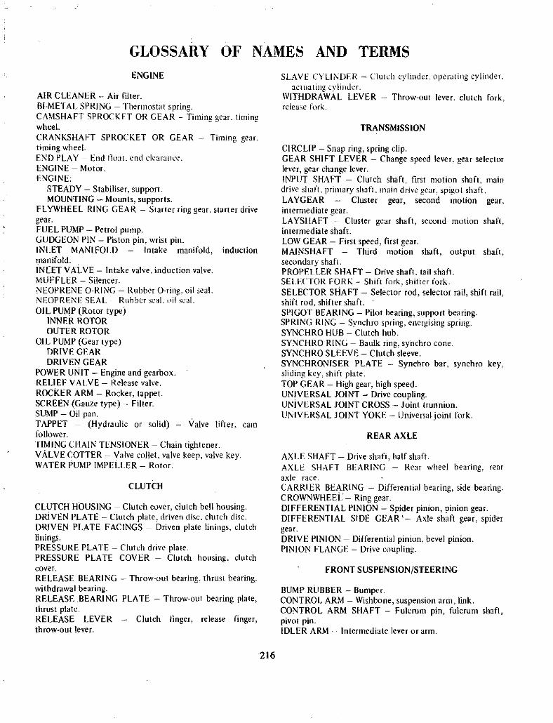
GLOSSARY OF NAMES AND TERMS
ENGINE
AIR CLEANER Air filterBI METAL SPRING Thermostat springCAMSHAFT SPROCKET OR GEAR Timing gear timingwheel
CRANKSHAFT SPROCKET OR GEAR Timing gear
timing wheelEND PLAY End tlUJt end clearanl c
ENGINE MotorENGINE
STEADY Stabiliser supportMOUNTING Mounts supports
FLYWHEEL RING GEAR Starter ring gear starter drive
gearFUEL PUMP Petrol pumpGUDGEON PIN Piston pin wrist pinINLET MANIFOLD Intake manifold induction
manifoldINLET VALVE Intake valve induction valve
MUFFLER SilencerNEOPRENE Q RING Rubber O ring oil eal
NEOPRENF SEAL Rubber selL nil seal
OIL PUMP Rotor typeINNER ROTOROUTER ROTOR
OIL PUMP Gear typeDRIVE GEARDRIVEN GEAR
POWER UNIT Engine and gearboxRELIEF VALVE Release valve
RockER ARM Rocker tappetSCREEN Gauze type FilterSUMP Oil panTAPPET Hydraulic or solid Valve lifter cam
follower
TIMING CHAIN TENSIONER Chain tightenerVALVE COTTER Valve collet valve keep valve keyWATER PUMP IMPELLER Rotor
CLUTCH
CLUTCH HOUSING Clutch cover clutch bell housingDRiVEN PLATE Clutch plate driven disc clutch discDRJVEN PLATE FACINGS Driven plate linings clutch
liningsPRESSURE PLATE Clutch drive platePRESSURE PLATE COVER Clutch housing clutch
cover
RELEASE BEARING Throw out bearing thrust bearingwithdrawal bearingRELEASE BEARING PLATE Throw out bearing platethrust plateRELEASE LEVER Clutch linger release fingerthrow out lever
SLAVE C LINDER Clutch vlind r operating cylinderactuating vlinder
WITHDRAWAL LEVER Throw oUl lever clutch forkrelease fork
TRANSMISSION
CIRCLlP Snap ring spring clipGEAR SHIFT LEVER Change speed lever gear selectorlever gear change lever
INPUT SHAFT Clutch shaft first motion shaft maindrive shaft primary shJfl main drive gear spigot shaftLAYGEAR Cluster gear second motion gearintermediate gearLAYSHAFT Cluster gear shaft second motion shaft
intermediate shaftLOW GEAR First speed first gearMAINSHAFT Third motion shaft output shaft
secondary shaftPROPELLER SHAFT Drive shaft tail sh3ftSELECTOR FOR Shift fork shifter tork
SELECTOR SHAFT Selector rod selector rail shift railshift rod shifter shaftSPIGOT BEARING Pilot bearing support bearingSPRING RING SVl1chro spring encrgising springSYNCHRO HUB Clutch hub
SYNCHRO RING Baulk ring synchro cone
SYNCHRO SLEEVE Clutch sleeveSYNCHRONISER PLATE Synchro bar synchro keysliding key shift plateTOP GEAR High gear high speedUNIVERSAL JOINT Drive couplingUNiVERSAL JOINT CROSS Joint trunnion
UNIVERSAL JOINT YOKE Universal joint fork
REAR AXLE
AXLE SHAFT Drive shaft half shaftAXLE SHAFT BEARING Rear wheel hearing rear
axle race
CARRIER BEARtNG Differential bearing side bearingCROWNWHEEL Ring gearDIFFERENTIAL PINION Spider pinion inion gearDIFFERENTIAL SIDE GEAR Axle shaft gear spidergearDRIVE PINION Differential pinion bevel pinionPINION FLANGE Drive coupling
FRONT SUSPENSION STEERING
BUMP RUBBER BumperCONTROL ARM Wishbone suspension arm link
CONTROL ARM SHAFT Fulcrum pin fulcrum shaft
pivot pinIDLER ARM Intermediate lever or arm
216

KING PIN Swivel pinPITMAN ARM Steering arm drop arm sector shaft arm
SECTOR SHAFT Roller shaft pitman arm shaft droparm shaftSHOCK ABSORBER DamperSTABILlSER BAR Ride stabiliser sway barSTEERING ARM Knuckle arm steering lever
STEERING CONNECTING ROD Tie rod relay rod
STEERING LINKAGE Track rods
STEERING GEAR Steering gearbox steering box
STEERING SHAFT Worm shaft steering columnSTUB AXLE Swivel axle
STUB AXLE SUPPORT Steering knuckle support swivellink control arm linkTiE ROD Track rod steering link rodTIE ROD BALL JOINT Tie rod endWHEEL ALIGNMENT Toe in track alignment
BRAKES
BACK PLATE Brake plate backing plateFLEXI BLE BRAKE PIPE Brake hose flexible connector
PISTON PlungerPRIMARY CUP Main cup maio rubber seaLRETURN SPRING Pull off spring retractor springSECONDARY CUP Piston seal
WHEEL CYLINDER CUP Wheel cylinder rubber wheelcylinder seal
WHEELCYLINDER Actuating cylinder
ELECTRICALADJUSTABLE CONTACT Breaker pointALTERNATOR AC GeneratorBREAKER ARM CONTACT Breaker arm pointCAPACITOR CondensorCOURTESY LIGHT Interior light roof lightDIPPER SWITCH Dimmer switchFUEL GAUGE Petrol gaugeGENERATOR DynamoGENERATOR REGULATOR Voltage regulator controlbox
GLOBE Bulb lampTURN SIGNAL LIGHT Direction indicator light llasherlight trafficator lightTURN SIGNAL SWITCH Direction indicator switchflasher switch trafficator switchHEADLAMP Head light main lightHIGH TENSION LEADS Plug wiresHORN PUSH Horn switch horn buttonINSTRUMENT LIGHT Panel lightLENS lass rvslal
NUMBER PLATE LIGHT Licence plate lightMEDALLION Name plate cover
PARKING LIGHT Side light side lampREGULATOR AlternalO regulator alternator COl1trolROTOR ARM Rotor buttonSTOP LIGHT Brake lightSTARTER Starter motorSTARTER DRIVE Bendix gear drive pinionTAIL LIGHT Rear lightTEMPERATURE GAUGE Heat gaugeWARNING LIGHT Indicator lightWINDSCREEN WIPER Windshield wiper
BODY
DOOR GLASS Door window window glassFENDER Mudguard wingGLASS LIFT CHANNEL Window lift channel
GLASS REGULATOR Window lift regulator windowwinder
GLASS RUN CHANNEL Glass channel glass runner
bailey channelHEADLINING Roof liningHOOD Bonnet engine compartment lidLUGGAGE COMPARTMENT Boot
REAR GLASS Back light back window
VENTILATOR GLASS No draught ventilator vent glassventilator flipper window quarter glassWEATHERSTRIP WeathershieldWINDSCREEN Windshield
217

DatsWl1000
4 door sedan1899
nil
white
START 47904930
13cwt
OPTIONSCOLORMILEAGEFINISH
MAKE
MODELBODY TYPEPRICE
WEIGHT
FUEl CONSUMPTIONOverall
Cruising35 2 rnpg
36 39 mpg
TEST CONDITIONSWeather fine Surface hot mix bitumen Load twopersons Fuel premium gradeSPEEDOMETER ERRORIndicated mph 30 40 50 60 70
Actual mph 30 37 45 53 62
PERFOR JA CE2320 it min
16 4 mph4660 rpm4250 rpm
24
Piston speed at m6X bhpTop gear mph per 1000 rpm
Engine rpm at max speedEngine rpm at cruising speedLbs laden per gross bhp power to weightMAXIMUM SPEEDSFastest run
Average of all runs
Speedometer indication fastest run
In gears 1st 23 mph 2nd 38 mph 3rd
82 mphACCELERATION
through gears0 30 mph0 40 mph0 50 mph0 60mph0 70 mph
82 mph82 mph89mph
53 mph 4th
44 sec
8 1 see
12 2 sec
18 2 sec
23 0 sec
4thgear8 2sec
8 2 sec
11 5sec
12 5see
20 40 mph30 50 mph40 60 mph50 70 mph
STANDING QUARTER MILEFastest run
Average of all runs
3rd gear6 0 see
7 5 sec
7 5 see
20 2 see
20 3 sec
4TH
STANDI G V4Mil E20 3 V
AD
MPH
2L
oc
1
oc
4C
TOP PEED82 KP H
x1ST
2 PH
ACCDERATION THROUGHGEARS WITH CHANGE
POtNTS
01611LI4410 1520 n 10 1S 40
MPH eLAPSED TIME IN SECONDS
Road test figures courtesy Wheels Magazinefrom its October 68 Sydney report
SPECIFIC TIONS
ENGINE
CylindersBore and stroke
Cubic capacityCompression ratioValves
Carburettor
Fuel pumpOil filter
Power at rpmTorque at rpm
TRANSMISSIONTypeClutchGear lever locationDirect ratio 1st
2nd
3rd4thFinal drive
CHASSIS and RUNNING GEAR
ConstructionSuspension front
Suspension rear
Shock absorberssteering typeTurnS l to I
Turning circleSteering wheel diameterBrakes typeDimensionsFriction areaDIMENSIONSWheelbaseTrack frontTrack rear
LengthHeightWidth
Fuel tank capacitylYRESSizePressures
Make on test car
GROUND CLEARANCE
Registered
218
four in line73mm by 59mm
988 cc
8 5 fa 1
overhead pushrod2 bbl HaUachi d draft
mechanical
full flow62 8 at 6000 rpm
61 51b ft at 4000 rpm
4 speed all syncro
single dry platefloor3 762 t7
140100
4111 to t
unitarywishbones transverse spring
leaf springstelesCopic
recirc 15 1 ratio2 8
28 2 ft
15 indrum drum
8 in diameter89 sq In
7 ft 5 in
3ft tOI in3ft 10 in
12 ft 6 in
4ft 5in4ft 8il in
7 gal
5 50 12
17 psiDunlop Dunsafe
7i in

33lfl 17
I 0
00
q 375
MAKEMODEL 1000BODY TYPE
Datsun
coupe 10002 dr coupe4 dr sedan
2145 2119
ntlwhite white
PRICE
OPTIONSCOLORWEIGHT
t3 25 ewt 13 1ewtFUEL CONSUMPnONOverall
CruisingTEST CONDITIONSWeatherSurfaceLoad
Fuel
SPEEDOMETER ERRORIndicated mphActual mph
32 mpg 29 mpg34 38 mpg 30 34 mpg
tinehot mix bitumen
2 persons
premium grade
302829 5
403739 0
504748 0
6057
57 0
70
6667 0
PERFORMANCIl
Piston speed at Max bhp 2310 ftminTop gear mph per 1000 rpm 15 5mphEngine rpm at Max speed 5350rpm 4900rpmLbs laden per gross bhp power to weight 22 6 23 6MAXIMUM SPEEDSFastest run 89 0 mph 78 2mphAverage of all nms 86 4mph 76 0mphSpeedometer indication fastest run 92 mph 81 mphIn gears1st 29 mph 30 2nd 49 mph 50 3rd 75 mph 76
4th 86 mphAcceleration through gears0 30mph0 40mph0 50 mph0 60 mph0 70 mph0 80 mph
4 8 sees
7 2 sees
0 5sees
15 2sees
210sees
32 6secs
8 2 secs
006 sees
050 secs
23 2 sees
36 5 sees
Figures tor Automatic Sedan in brackets
JuP il
II j
3Rcr75 MPt
STAN
7fIM U 204
I OMT1G
V6lTANDIIIG
IMILE 2 0
2ND
49 2ND
I I ISOMP
7C
6C
50
4tTOP SPEED
I86 4 MPH
76 0 P H
AcmERATll THRJGH IGEARS WITH CHANGEPOINTS
t 1J5 C 15 H
ELAPSED TIME IN SECONDS
20
Road test figures courtesy Wheels Magazinefrom its August 1969 Sydney report
20 40 mph30 50 mph40 60 mph50 70 mphSTANDING QUARTERFastest run
Average of all rWlS
3rd gear6 4 sees
6 7 sees
7 6 sees
10 0sees
MILE
4thgear9 9 sees
10 1 sees
11 2 sees
13 7 sees
Drive5 5sees7 0 sees
10 7sees
218 sees
SPECIFIATIONS
20 3 sees 23 5 sees
20 4 sees 24 0 sees
ENGINECyllndersBore and strokeCubic capacityCompression ratio
ValvesCarburettorPower at rpmTorque at rpm
TRANSMISSION
Type 4 speedClutcl1Gear lever locationOverall ratio
Final driveCHASSIS and RUNNINGCOnatnIctionSUSPENSIONFrontRearShock absorbersSTEERINGTypeTUrns I to I
Tumlng circleBlAKES
TypeDIMENSIONSWheelbaseTrack front
Track rear
LengthHetghtWtdthFuel tank capacityTYIESSizeMake on teat car
GROUND CLEARANCERegistered
219
four in line73mm by 59mm
988 cc
90 to 1ohv
2 bbl downdraught66 at 6000 rpm 62 at 6000 rnm
65 7Ib lt at 4000rpmlt at 4
Nissan 3 speed tully automaticsdp torque converter
central floor column quadrant1st 3 76 2 458 2nd 2 17 1458
3rd 140 l000l 4th 1004 111 to 1
GEAR
wishbones
unitary
transverse leafleaf springs
telescopic
recirc ball3 4
26 It
dnnn front and rear
89 8in
46 9 tn46 5in
12 ItUin l21t 5 6 tn
41t 36tn 4ft 5 in4ft 89 in
S gals 7 7 gals
5 50 12
Dunlop Dunsafe
6 7 in 6 3 tn

MAKEBODY TYPEOPTIONS
MILEAGE START
FINISH
Datsun
4 dr edanNil
16092023
MODEL 1200 Manuall
Automatic13 9 ewt 690 Kg
2108 2334Red
WEIGHTPRICECOLOR
fUEL CONSUMPTIONOverall Manual 31mpg 13 2k ll Auto 28mpg
10 9 k IlCruising Manual 32 36 mpg 035 15 3 k l Auto
29 33 mpg 12 3 14 k l
rEST CONDITIONSWeather tine Surface bitumen bonded gravel Load
two persons Fuel premium gradeSPEEDOMETER ERROR mphIndicated 30 40 50 60 70
Actual 8 37 46 54 5 64
PIlRFon I CPiston speed at max bhp 70 050 cm min 2760 ft min
Tcp gear mph per 1000 rpm 16 0 25 8 kphEngine rpm at max speed 4200
Lbs laden per gross bhp lXlWer toweight 22 2
10kg bhpMAXIMUM SPEEDSFastest run 121 kph 75 5 mphAverage of all runs 120 5kph 75 0 mphSpeedometer indication fastest run 146 kphJ 91 0 mphIN GEARSAutomatic Drive
1st 28 mph 45 kph2nd 54mph 87kph3rd 75mph 120kphlACCELERATION Through gears
0 30 mph0 40mph0 50mph0 60mph0 70 mph
Held
46mph 74kph60 mph 97 kph75mph 120kph
6 1 sec
94see
13 3 see
19 5sec29 5 sec
J3
7sJPH ISTANC NG V4 I I IMILE 21 5St
2ND tJND I HELD4MPH V I
MPH
PH I II
Xl15T I I28MP
2
IACCnERATIOH THRC1JGH
GEARS WITH CHANGE
L l JPOJ j5 15 H
ELAPSED TIME IN SECONDS
7C
IC
5C
4C
TOP SPEED75 MPH
MPH
Road test figures courtesy Wheels Magazinefrom its September 1970 Sydney report
20 40 mph30 50mph40 60 mph50 70 mphSTANDING QUARTER MILEFastest run
Average all runs
BRAKINGFrom 30 mph to 0
From 60 mph to 0
SPEIFlf TIOSENGINECylindersBore and strokeCUbic capacityCompression ratioValves
CarburettorsPower at rpm
Torque at rpmTRANSMISSIONType 4 speed all syncro Borg Warner Type 35
Clutch Single dry plate fluidGear lever location Central central T bar
Overall ratio 1st 3 76 2 46 2nd 2 17 146 3rd 140100 4th 1000 finat drive 3 90
CHASSIS AND RUNNING GEARCOnstructionSuspension front
Suspension rear
Shock absorbers
steering typeTurns 1 to I
Turning circleBrakes typeDimensionsDlhUNSIONSWheelbaseTrack frontTrack rear
LengthHeightWidthFuel tank capacityTyres SizeMake on test car
GROUND CLEARANCE
220
Autcmatic
2nd Gear6 36 47 39 1
Drive4 t527 1tt6
21 5 sec
2155 see
l Osec
3 05 sec
4 in line73 by 70 mm 2 87 by 2 76 in
1171cc 715cuin
9 0 W tohv
single downdraft Aisan SU69 bhp at 6000 rpnl
70 ft lb 10 6 kg m at 3600 rpm
integralcoil struts anti roll bar
lea springstelescopic
recirculating ball4 15 to 1 ratio
27ft 82mdrum front and rear
8 in 20 2 em diameter
90 6 in 243 em
48 8 in 124 ern
49 0 in 125 em
12 ft 69 in 405 em
4 ft 6 7 in 139 cm
4 ft 10 9in 124 cm
88 galls 32 5 litres600 x 12 155 x 305
Dunlop Dunsafe
Registered 6 6 16 8 em

Road test figures courtesy Wheels Magazine from its Apri I 1971 reportACCELERATION hhrough gears039 mph040 mph050 mph0 60 mph070 mphQ80mph
MAKE
MOOEL
BODY TYPEPRtCE
COLOR
MtLEAGE START
MILEAGE FtNtSH
WEtGHT
Datsun
1200 Coupe2door Coupe
24t4
Cream
2t
608
1520 Ib 1695 kg
FUEL CONSUMPTIONOverall
Cruising31 mpg
37 38 mpg
TEST CONDITIONS
WeatherSurface
Load
Fuel
Hot fine
Hot mix
2 persons
premium
SPEEDOMETER ERROR ImphIndicated 30 40
Actual 28 4 38 1
50 60
46 8 55 8
70
63 9
f
PERFORMANCE840 m min 2760 ft min
16
5500
22 Ib 110 kg
Piston speed at max bhpTop gear mph per 1000 rpmEngine rpm at max speedLbs laden per gross bhp power ta weight
MAXIMUM SPEEDS
Fastest run
Average of all ns
Speedometer ndication fastest run
141 kph 88 mph136 kph 85 mph157 kph 98 mph
IN GEARS
1st2nd
3rd
4th
284mph 45 kphl 6000 rpm51 mph 82 kph 6000 rpm
77 5 mph 124 kph 6000 rpm88 mph 141 kphl 5500 rpm
ST OING1
MILEJ19 J
I 3RI H
VII 2ND hJPH
V17r2BM1
I I
PH
III
III
c
4C
IlOP SPEED88 MPH
I Ir
r
I
ACCELERATION THROUGHGEARS WITH CHANGE
POINTS
o
MPH
5l I 1
10 15 20 25 30 35 J
EUlPSED TIME IN SECONDS1
2040 mph3050 mph4060 mph5070 mph
STANDING OUARTER MtLE
Fastest run
Average all runs
BRAKING
From 30 mph to 0
From 60 mph to 0
2nd gear4 0 see
4 2 see
5 4 see
77 see
10 9 see
15 5 see
22 1 see
32 see
4th gear11 6 see
9 6 see
10 5 see
124see
3rd gear8 0 see
7 0 see
8 2 see
83 see
19 1 see
19 3 see
1 7 see
3 6 sec
SPECI FICATIONS
ENGINE
CylindersBore and Stroke
Cubic CapacityCompression Ratio
Varves
Carburettors
Fuel PumpOil Filter
Power at rpmTorque at rpm
TRANSMtSSIONTypeClutch
Gear lever location
RATIOS
2 87Four in line
2 76 73 mm 70 mm
715cu 1171 I9to 1
Overhead pushrodTwo barrel downdraft
Meehan ical
Full flow
69 bhp 600070 Ibltt 19 7 kglm @3600
4 manual all syncroI
SDP
Floor console
Direct1st 3 76
2nd 2 173rd 1404th 1 0Final Drive 3 9 1
CHASSIS and RUNNING GEAR
Construction
Suspension Front
Suspension Rear
Shock Absorbers
Steering TypeTurning Circle
Steering Wheel Diameter
Brakes Type
DIMENSIONS
Wheelbase
Track Front
Track Rear
LengthHeightWidth
Fuel Tank Capacity
TYRES
Size
Pressures
Make on Test Car
GROUND CLEARANCE
Registered
221
Overall
14 66
8 46
5 46
3 9
UnitaryMcPherson struts anti roll bar
Semielliptic leafs
TelescopicRecirculating ball
26 tt8 8 2 m
15 38 1 em
Disc drum
90 6 230 eml48 8 in 124 cm
49 124 5 em
12 ft6 in 382 em
4ft 5 135cm
4ft 11 6 in 1515 em
8 5 gals 38 litres
t55SR 12
24 Ib all round
Dunlop SP 3
6 7 in 17 em

DATE REMARKS
222

QATE1
REMARKS
J
223

DATE REMARKS
J
Printed by Kenmure Press Pty Ltd 50 Derby Street North Lidcombe New South Wales 2141
r

D i T
at t t t lJ ic
1
b iid 5d bj r iT 1Ziizk jj 0 tiJt