dixonvalve.com • customer service: 877.963 · 2 dixonvalve.com 877.963.4966 877.963.4966...
TRANSCRIPT

MA
NU
FA
CT
UR
ING
• Q
UA
LIT
Y •
SER
VIC
E •
MA
NU
FA
CT
UR
ING
• Q
UA
LIT
Y •
SER
VIC
E •
MA
NU
FA
CT
UR
ING
• Q
UA
LIT
Y •
SER
VIC
E •
MA
NU
FA
CT
UR
IN
®
Band Clampsand
Accessories
dixonvalve.com • Customer Service: 877.963.4966

877.963.4966 3dixonvalve.com877.963.49662 dixonvalve.com
Band Clamps
F and FO series ...............................................................................................................................................................4
K series ............................................................................................................................................................................5
Smooth ID .....................................................................................................................................................................6-7
Band and Buckle ...........................................................................................................................................................8-9
Clamp Selection Guide ......................................................................................................................................................10
Preparing the Hose............................................................................................................................................................. 11
Tools
Clamp Cutter ..................................................................................................................................................................12
Mallet .............................................................................................................................................................................12
51960 Screw-Action ......................................................................................................................................................12
C2 Jack-Type .................................................................................................................................................................14
F1 ...................................................................................................................................................................................16
F100 ...............................................................................................................................................................................18
F175 ...............................................................................................................................................................................20
F38 .................................................................................................................................................................................22
F40 .................................................................................................................................................................................24
Safety
Dixon's couplings and retention devices are designed to work safely for their intended use. The selection of the proper hose, coupling and retention device, and the proper application of the coupling to the hose are of utmost importance.
Users must consider the size, temperature, application, media, pressure and hose and coupling manufacturer's recommendations when selecting the proper hose assembly components. Dixon recommends that all hose assemblies be tested in accordance with the Association for Rubber Products Manufacturer's (ARPM) recommendations and be inspected regularly (before each use) to ensure that they are not damaged or have become loose. Visit ARPMINC.com for more information.
Where safety devices are integral to the coupling, they must be working and utilized. The use of supplementary safety devices such as safety clips or safety cables are recommended.
If any problem is detected, couplings must be removed from service immediately.
Dixonisavailabletoconsult,trainandrecommendtheproperselectionandapplicationofallfittingswesell.Westrongly recommend that distributors and end users make use of Dixon's Testing and Recommendation Services. Call 877.963.4966 or click dixonvalve.com to learn more.
Table of Contents

877.963.4966 3dixonvalve.com877.963.49662 dixonvalve.com
The use of band style clamps is a proven method of retaining hose couplings in industrial hose.
To achieve proper retention and sealing of the hose coupling in the hose, it is imperative that these clamps be installed correctly. Please follow the manufacturer’s recommendations as to the proper selection and installation of band clamps.
When installing multiple clamps, the buckles must be offset around the hose, (reference page 8), eliminating the possibility of a straight line leak under the buckle area.
Proper installation of band clampsClamps installed with buckles equally rotated.
Improper installation of band clampsClamps installed with buckles in-line.
Thefirstclampshouldbeinstalledjustinsidethemarkonthehosefurthermostfromthehoseend(referencepage11).
Leaving excess band material turned back over the buckle does not improve the performance of the clamp. In fact, a safety hazard develops from this practice by leaving sharp edged material exposed.
Band Clamps Procedure 2100-2199 PDF's
Band Clamps Procedure 2100-2199 Video's
Procedure 2100: Pre-Formed Band
Clamp Using Pneumatic Roll-Over
Tool
Procedure 2101: Pre-Formed Band
Clamp Using Punch Style Tool
Procedure 2102: Pre-Formed Band
Clamp Using Punch Style Tool with Roll-
Over Tool Attachment
Procedure 2103: Pre-Formed Band
Clamp Using Screw-Action Tool with Roll-Over Tool Attachment
Procedure 2104: "Clamp-It" Band and Buckle Installation
Using Screw Action Tool
Reference pages 10 and 11 for selection and preparation guidelines.
Procedure 2100: Pre-Formed Band
Clamp Using Pneumatic Roll-Over
Tool
Procedure 2101: Pre-Formed Band
Clamp Using Punch Style Tool
Procedure 2102: Pre-Formed Band
Clamp Using Punch Style Tool with Roll-
Over Tool Attachment
Procedure 2103: Pre-Formed Band
Clamp Using Screw-Action Tool with Roll-Over Tool Attachment
Procedure 2104: "Clamp-It" Band and Buckle Installation
Using Screw Action Tool
Safety Recommendations

877.963.4966 5dixonvalve.com877.963.49664 dixonvalve.com
style F(pre-formed)
The F series double-wrapped metal band clamp is formed to a given diameter with a tailpiece through the buckle.
style FO(open end)
The FO clamp is open-ended and may be applied easily without sliding the clamp over the hose end.
F and FO Series Clamps
Features:• install with center punch tools F1, F38, F40 and F100,
other manufacturer's punch style tools may also be used• on stainless clamps, bands are 300 series stainless steel,
buckles are 302 series stainless steel• double-wrapped• triple-punched• holds permanently• sold in package quantities only
BandWidth ID Band
THK
Stainless SteelPart #
PkgQty
BandTHK
Galvanized SteelPart #
PkgQty
⅜" 13/16" .020 FS3 100 .025 F3 1001-3/8" .020 FS311 100 .025 F311 100
⅝"
1" .022 FS4 100 .025 F4 1001-1/4" .022 FS5 100 .025 F5 1001-1/2" .022 FS6 100 .031 F6 1001-3/4" .022 FS7 100 .031 F7 100
2" .022 FS8 100 .031 F8 1002-1/4" .022 FS9 100 .031 F9 1002-1/2" .022 FS10 50 .031 F10 502-3/4" .022 FS11 50 .031 F11 50
3" .022 FS12 50 .031 F12 503-1/2" .022 FS14 50 .031 F14 50
4" .022 FS16 25 .031 F16 254-1/2" .022 FS18 25 .031 F18 25
5" .022 FS20 25 .031 F20 256" .022 FS24 25 .031 F24 257" .022 FS28 25 .031 F28 258" .022 FS32 25 .031 F32 25
BandWidth ID Band
THK
Stainless SteelPart #
PkgQty
BandTHK
Galvanized SteelPart #
Pkg Qty
⅜"13/16" .020 FOS3 100 .025 FO3 1001-3/8" .020 FOS311 100 .025 FO311 100
2" .020 FOS316 100 .025 FO316 1003-1/8" .020 FOS325 100 .025 FO325 100
⅝"
2" .022 FOS8 100 .025 FO8 1002-1/2" .022 FOS10 50 .025 FO10 50
3" .022 FOS12 50 .031 FO12 503-1/2" .022 FOS14 50 .031 FO14 50
4" .022 FOS16 50 .031 FO16 504-1/2" .022 FOS18 50 .031 FO18 50
5" .022 FOS20 25 .031 FO20 256" .022 FOS24 25 .031 FO24 257" .022 FOS28 25 .031 FO28 258" .022 FOS32 25 .031 FO32 259" .022 --- 25 .031 FO36 25
10" .022 --- 25 .031 FO40 2512" .022 --- 25 .031 FO48 2514" .022 --- 10 .031 FO56 10

877.963.4966 5dixonvalve.com877.963.49664 dixonvalve.com
• center punched
• rolled over
punch indentation for ease of center punching
Note: ¾" must be applied with the F175 hand tool found on pages 20-21.
K Series Clamps
Features:• on stainless clamps, bands are 300 series stainless steel,
buckles are 302 series stainless steel• designed to be slipped over the hose end before the fittingisinserted• can be center punched or rolled over, install with the cen-
ter punch or roll over tools • Fast-Lok™ tools: F1, F40, F100 • Super Strap Tools: 51960 screw action with 51970
adapter • Bandit®: S100 air tool with S180 Jr. head, C-001 hand
tool with J001 Jr. adapter, S350 air tool with S260Jr.head,T-240for⅜"onlyorT-250for⅜"and⅝",S-38for⅜"and⅝",J-102Pok-It™for⅜"only.
• Punch-Lok®tools:P-1000for⅜"and⅝",P-3000for⅜"only,P-38for⅜"and⅝"
• sold in package quantities only
BandWidth ID Band
THK
Stainless SteelPart #
PkgQty
BandTHK
Galvanized SteelPart #
PkgQty
⅜" 13/16" .025 KS3 100 .025 K3 1001-3/8" .025 KS311 100 .025 K311 100
⅝"
1" .031 KS4 100 .030 K4 1001-1/4" .031 KS5 100 .030 K5 1001-1/2" .031 KS6 100 .030 K6 1001-3/4" .031 KS7 100 .030 K7 100
2" .031 KS8 100 .030 K8 1002-1/4" .031 KS9 100 .030 K9 1002-1/2" .031 KS10 50 .030 K10 502-3/4" .031 KS11 50 .030 K11 50
3" .031 KS12 50 .030 K12 503-1/2" .031 KS14 50 .030 K14 50
4" .031 KS16 25 .030 K16 254-1/2" .031 KS18 25 .030 K18 25
5" .031 KS20 25 .030 K20 256" .031 KS24 25 .030 K24 257" .031 KS28 25 .030 K28 258" .031 KS32 25 .030 K32 25
BandWidth ID Band
THKStainless Steel
Part #PkgQty
¾"
2" .030 KS87501 1002-1/4" .030 KS97501 1002-1/2" .030 KS107501 502-3/4" .030 KS117501 50
3" .030 KS127501 503-1/2" .030 KS147501 50
4" .030 KS167501 254-1/2" .030 KS187501 25
5" .030 KS207501 256" .030 KS247501 257" .030 KS287501 258" .030 KS327501 25

877.963.4966 7dixonvalve.com877.963.49666 dixonvalve.com
The smooth inside diameter produces a uniform clamping surface to prevent leak paths.
Dixon Smooth ID Clamps
Application:For use with industrial hose made of stiffer, thinner thermo-plastics.
Features:• provide a uniform, gap-free inside diameter, and strong
holding power• Install with roll over type clamp tools and most common
band clamp tools such as the 51960 and 51970 band tools
• sold in package quantities only
BandWidth ID Band
THK201 Stainless Steel
Part #PkgQty
Galvanized SteelPart #
PkgQty
⅜"13/16" .025 JS201 100 JS301 100
1" .025 JS243 100 JS343 1001-3/8" .025 JS202 100 --- ---
2" .025 JS245 1 100 --- ---
½"1" .030 JS203 100 JS303 100
1-1/4" .030 JS204 100 JS304 1002-3/4" .030 JS230 100 JS330 1 100
⅝"
1-1/2" .030 JS205 100 JS305 1001-3/4" .030 JS206 100 JS306 100
2" .030 JS207 100 JS307 1002-1/4" .030 JS208 100 JS308 1002-1/2" .030 JS209 100 JS309 100
¾"
2-3/4" .030 JS210 50 JS310 1 503" .030 JS211 50 JS311 50
3-1/2" .030 JS212 50 JS312 504" .030 JS213 25 JS313 25
4-1/2" .030 JS214 25 JS314 255" .030 JS215 25 JS315 256" .030 JS216 1 25 --- ---7" .030 JS218 1 25 --- ---
1 stock quantities only
877.963.4966 7dixonvalve.com877.963.49666 dixonvalve.com
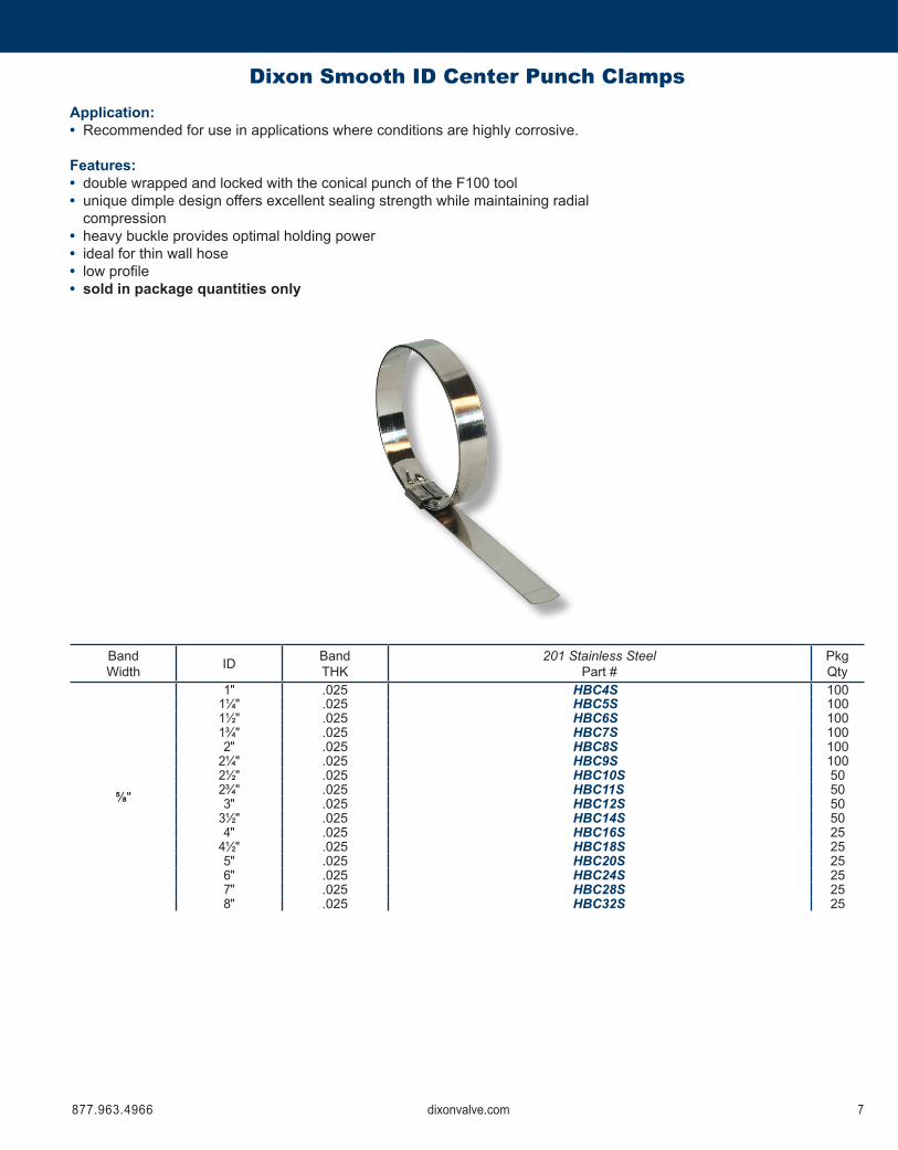
Dixon Smooth ID Center Punch ClampsApplication:• Recommended for use in applications where conditions are highly corrosive.
Features:• double wrapped and locked with the conical punch of the F100 tool• unique dimple design offers excellent sealing strength while maintaining radial compression• heavy buckle provides optimal holding power• ideal for thin wall hose• lowprofile• sold in package quantities only
BandWidth ID Band
THK201 Stainless Steel
Part #PkgQty
⅝"
1" .025 HBC4S 1001¼" .025 HBC5S 1001½" .025 HBC6S 1001¾" .025 HBC7S 1002" .025 HBC8S 100
2¼" .025 HBC9S 1002½" .025 HBC10S 502¾" .025 HBC11S 503" .025 HBC12S 50
3½" .025 HBC14S 504" .025 HBC16S 25
4½" .025 HBC18S 255" .025 HBC20S 256" .025 HBC24S 257" .025 HBC28S 258" .025 HBC32S 25

877.963.4966 9dixonvalve.com877.963.49668 dixonvalve.com
Band and Buckle
Features:• install with C2 or 51960 band clamp tools• economicalmethodofsecuringfittingstolargediameter
rubber hose (2" and above)• Do not use strapping and buckles made of different
metals, e.g. stainless steel strapping must be used with stainless steel buckles.
• sold in box quantities only
Caution! Strapping edges can be extremely sharp! All necessary precautions should be taken to prevent installer’s hands from being cut during the assembly process.
strapping buckles
BandWidth
BandThickness Length
201 Stainless SteelPart #
Galvanized SteelPart #
⅜" .025 100' SS375 SG375½" .031 100' SS500 SG500⅝" .031 100' SS625 SG625¾" .031 100' SS750 SG750
Band Width
201 Stainless Steel Pkg
QtyGalvanized Steel Pkg
QtyPart # Part #
⅜" CS375 100 CG375 100½" CS500 100 CG500 100⅝" CS625 100 CG625 100¾" CS750 100 CG750 50

877.963.4966 9dixonvalve.com877.963.49668 dixonvalve.com
Set Screw Buckles
Applications:• Used in applications when a temporary clamp is desired
or space limitations do not allow for tool roll-over• set screw locks band after tensioning.• sold in box quantities only
1 ¾"bucklemaybeusedwith⅝"band
Band Width201 Stainless Steel Pkg
QtyPart #⅜" SSB375 50½" SSB500 25¾" SSB750 1 25
Stainless Steel Banding
Features:• resistant to moisture• built-in handle• full view of available band• easy to dispense and recoil
BandWidth
BandThickness Length Package Type
201 Stainless SteelPart #
½" .030 100' plastic blue tote ST204B⅝" .030 100' plastic green tote ST205G¾" .030 100' plastic red tote ST206R
877.963.4966 11dixonvalve.com877.963.496610 dixonvalve.com
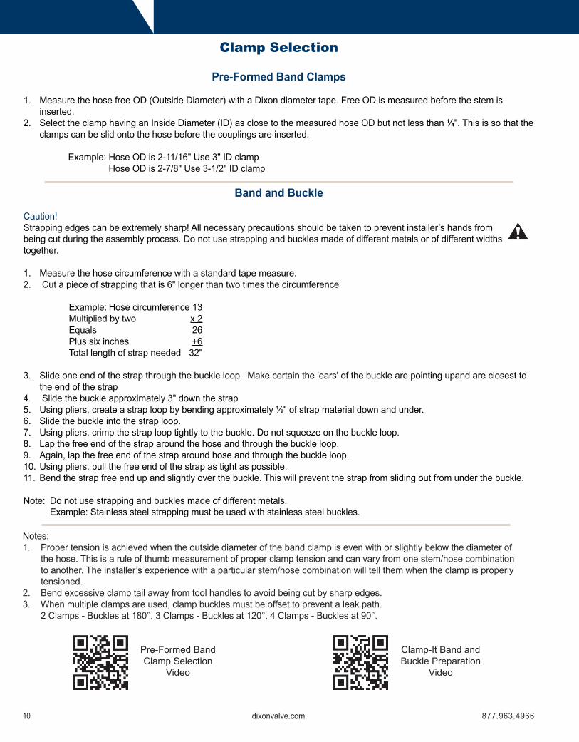
Pre-Formed Band Clamps
1. Measure the hose free OD (Outside Diameter) with a Dixon diameter tape. Free OD is measured before the stem is inserted.
2. Select the clamp having an Inside Diameter (ID) as close to the measured hose OD but not less than ¼". This is so that the clamps can be slid onto the hose before the couplings are inserted.
Example: Hose OD is 2-11/16" Use 3" ID clamp Hose OD is 2-7/8" Use 3-1/2" ID clamp
Band and Buckle
Caution!Strapping edges can be extremely sharp! All necessary precautions should be taken to prevent installer’s hands from being cut during the assembly process. Do not use strapping and buckles made of different metals or of different widths together.
1. Measure the hose circumference with a standard tape measure.2. Cut a piece of strapping that is 6" longer than two times the circumference
Example: Hose circumference 13 Multiplied by two x 2 Equals 26 Plus six inches +6 Total length of strap needed 32"
3. Slide one end of the strap through the buckle loop. Make certain the 'ears' of the buckle are pointing upand are closest to the end of the strap
4. Slide the buckle approximately 3" down the strap5. Using pliers, create a strap loop by bending approximately ½" of strap material down and under.6. Slide the buckle into the strap loop.7. Using pliers, crimp the strap loop tightly to the buckle. Do not squeeze on the buckle loop.8. Lap the free end of the strap around the hose and through the buckle loop.9. Again, lap the free end of the strap around hose and through the buckle loop.10. Using pliers, pull the free end of the strap as tight as possible.11. Bend the strap free end up and slightly over the buckle. This will prevent the strap from sliding out from under the buckle.
Note: Do not use strapping and buckles made of different metals. Example: Stainless steel strapping must be used with stainless steel buckles.
Notes:1. Proper tension is achieved when the outside diameter of the band clamp is even with or slightly below the diameter of
the hose. This is a rule of thumb measurement of proper clamp tension and can vary from one stem/hose combination to another. The installer’s experience with a particular stem/hose combination will tell them when the clamp is properly tensioned.
2. Bend excessive clamp tail away from tool handles to avoid being cut by sharp edges.3. When multiple clamps are used, clamp buckles must be offset to prevent a leak path. 2 Clamps - Buckles at 180°. 3 Clamps - Buckles at 120°. 4 Clamps - Buckles at 90°.
Pre-Formed Band Clamp Selection
Video
Clamp-It Band and Buckle Preparation
Video
Clamp Selection

877.963.4966 11dixonvalve.com877.963.496610 dixonvalve.com
Cut Hose to LengthCut Ends Square (Lack of a square cut on the hose end can reduce coupling retention.)For hoses having a helical wire:1. Determine the direction the helical wire is pointing in. This is necessary as proper installation of pre-formed band
clamps and bands and buckles rely upon proper orientation of the clamp tail with the helical wire. See illustration below.
2.Ifhelicalwireisnotusedforstaticgrounding,trimthewirebackintothecarcassofthehose.Thisistopreventinjuryduring use of the assembly.
Clean Hose IDMark the hose for proper clamp placementAll styles of band clamps (both pre-formed and bands & buckles) require proper placement to achieve maximum retention. Place marks on hose for proper clamp placement as follows:1. Determine shank serration style a. Symmetrical (all serrations the same size), e.g. King combination nipples, suction couplings, etc. b. Pronounced (some serrations are higher than the other serrations), e.g. Cam and groove, King nipples, etc.2. Symmetrical Shanks a. Determine number of clamps required. Reference Dixon’s Pressure Chart for correct number of clamps to install
based on coupling style and size. b. Place the shank next to the hose to simulate the shank being fully inserted. c. Place a mark on the hose that corresponds with the point of the last serration. d. When multiple clamps are required, place corresponding number of marks equally spaced from one another and the
hose end. e. Do not place a clamp directly on the hose end. Leave ¼"to⅜"spacebetweenthehoseendandthelastclamp
installed.3. Pronounce shanks a. Place the shank next to the hose to simulate the shank being fully inserted. b. Place a mark on the hose that corresponds with the point of each pronounced serration. c. The correct number of clamps to install will be equal to the number of marks placed on the hose.Static Grounding When required, proper static grounding is essential. Typically, this is accomplished by bending the built-in static wire or the helical wire (or wires) inside the hose ID so that it contacts the metal coupling. Caution should be taken to bend innomorewirethannecessary.Usually½"ofwirebentinissufficient.Othermethodsofstaticgroundingareavailableand may be required due to hose type, hose manufacturer or style of coupling to be installed. Always contact the hose manufacturerforproperstaticgroundingtechniquesforthatparticularhose.Improperstaticgroundingcanleadtofire,explosions,reducedassemblylife,damagetopropertyandinjuryordeathtopersonnel.Seal the Hose Ends At each end of the hose, the reinforcement is exposed to the outside elements. This exposure can lead to premature assembly failure especially if the end of the assembly is laying in a puddle of water or puddle of product. If the assembly istobesubjectedtotheseconditions,thehoseendsmustbesealed.Typically,rubbercementorshellacisused.Contactthe hose manufacturer for recommendations. Wire reinforce hoses can corrode to the point of failure near the clamp. Textile or fabric reinforced hoses can wick water or product to anywhere in the length of the hose and exit the cover at the weakest spot.Coupling Lubricant The coupling shank and the hose ID are to be lubricated prior to coupling insertion. Dixon recommends using Dixon Coupling Lubricant (DCL10 1 liter, DCL80 4 liters). Do not use hand soap, oil, grease, WD40, silicone spray, or other substances that may attack the tube material and / or reduce coupling retention.
General Preparation Instructions Video
Preparing the Hose for Assembly

877.963.4966 13dixonvalve.com877.963.496612 dixonvalve.com
Part #
F550
Clamp Cutter MalletFeatures:• malleable iron with rubber covered handles• weight: 2.11 lbs.• length: 14"
Features:• ductile iron head, wooden handle• weight: 2.65 lbs.• length: 12"
Part #
F225
Part #
51960
Features:• screw-action type tool for installing band and buckles• plated steel• weight: 4.17 lbs.• length: 12"
Part #
51970
Features:• adapter for 51960 for installing preformed clamps• for vise applications only• plated steel• weight: 1.23 lbs.• length: 10½"
Installation Tools
51960 Installation Tool
51970 Rollover Attachment

877.963.4966 13dixonvalve.com877.963.496612 dixonvalve.com
1Hold the tool in the left hand so that the cutter bail is on the bottom and the pulling dog lever is on top. Slide the strap tail through the slot on the right side of the tool.
2Press down on pulling-dog lever and rotate handle to begin tightening. Tighten strap to desired tension. Simultaneously relieve some tension while pushing the tool away as far as possible.
3Pull the cutter bail to cut the strap tail. Tap the buckle ears down to hold the cut strap tail in place
1. Slide the 51970 Roll - over attachment on to the head of the 51960 Screw - action tool.
2. With handle of 51970 facing installer, place 51960 in a vise and tighten.
3. Slide the clamp tail through the slot on the 51970.
4. Press down on pulling-dog lever and rotate handle to begin tightening.
5. Tighten clamp to desired tension.
6. Simultaneously relieve some tension while rolling hose towards cutter.
7. When clamp buckle engages cutter, pull handle.
Operating Instructions for the 51960 Installation Tool
Operating Instructions for the 51960 with 51970 Roll-Over Attachment

877.963.4966 15dixonvalve.com877.963.496614 dixonvalve.com
Features:• lightweight, side and front entry• jack-typeclampingtool• designed to provide easy installation of the band and
buckle system• forapplying⅜"and⅝"bandclamps• tooladjuststensionandlocksbuckleinplace• steel• weight: 3.09 lbs.• length: 14"
Part #
C2
Qty Per Tool Part Description Part #
1 Holding dog C-2072 Puller links FX-211A2 Puller links FX-211B1 Puller link pin C-2121 Pulling dog FX-2141 Pulling dog spring FA-2171 Pulling dog pin F-2331 Ball handle assembly FA-2201 Pusher puller assembly CA-2313 Retaining rings F-2421 Cutter EXP-2011 Crescent ring F-2321 Cutter handle C-2001 Holding dog pin F-2331 Holding dog spring F-2171 1/8" x 3/8" roll pin C-2432 3/16" x 5/8" roll pin C-236
Sliding Jack Replacement Kit
Part #
F205K
Feature:• fitstheF100,F175andC2tools
Illustrations are not in correct proportion to one another.
C-207 FX-211A FX-211B C-212
FX-214 FA-217 F-233 FA-220
CA-231 F-242 EXP-201 F-232
C-200 F-233 F-217 C-243
C-236
FX-214 FA-217 FX-211A FX-211B
Part Identification for the C2 Installation Tool
877.963.4966 15dixonvalve.com877.963.496614 dixonvalve.com
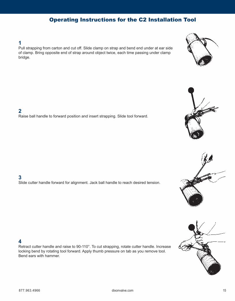
1Pull strapping from carton and cut off. Slide clamp on strap and bend end under at ear side ofclamp.Bringoppositeendofstraparoundobjecttwice,eachtimepassingunderclampbridge.
2Raise ball handle to forward position and insert strapping. Slide tool forward.
3Slide cutter handle forward for alignment. Jack ball handle to reach desired tension.
4Retract cutter handle and raise to 90-110°. To cut strapping, rotate cutter handle. Increase locking bend by rotating tool forward. Apply thumb pressure on tab as you remove tool. Bend ears with hammer.
Operating Instructions for the C2 Installation Tool

877.963.4966 17dixonvalve.com877.963.496616 dixonvalve.com
Qty Per Tool Part Description Item # Part #
1 Head 1 FI2011 Spring pin 2 FI2031 Punch 3 FI2021 Retaining ball 4 FI2051 Punch holder 5 FI2041 Pusher nose 7 FI2061 Spring 8 F2091 Holding dog 9 F2071 Nose 11 FA2311 Holding dog pin 12 F2336 Retaining ring 13 F2321 Head pivot pin 14 FI2331 Set screw 15 FI2501 Tension handle assembly 18 FA220I1 Tension handle shaft only 18B FA2221 Handle ball 21 FA2211 Slide 25 FA2281 Pulling dog pin 26 F2331 Pulling dog 27 FI2142 Dowel pin 28 FI2131 Link 29 F2111 Shaft 32A FA2321 Handle 32B FA2331 Compression spring 34 FI2453 Washer 35 F223
Features:• forapplying⅝"bandclamps• steel• weight: 3.15 lbs.• length: 12"
Part #
F1
Part Identification for the F1 Installation Tool

877.963.4966 17dixonvalve.com877.963.496616 dixonvalve.com
1Push tension handle all the way forward. Insert the clamp tail and push all the way into tool.
2Tighten the clamp with short downward strokes. Tension handle should be in down position at completion of tightening clamp.
If clamp tension needs to be released before locking, move slide back against spring. This raises the pulling dog.
3Holding tension handle down, lock clamp by hitting punch at least twice with mallet.
4Hold hose and raise the tool back and forth to break off clamp tail. Remove from tool by operating tension handle. When tail has moved through holding dog, raise tension handle and pull tail free.
Operating Instructions for the F1 Installation Tool

877.963.4966 19dixonvalve.com877.963.496618 dixonvalve.com
Features:• forapplying⅜"and⅝"bandclamps• steel• weight: 2.86 lbs.• length: 13"
Part #
F100
Qty Per Tool Part Description Part #
1 Punch head FX-2011 Punch F-2021 Punch head pin F-2331 Pusher nose F-2061 Holding dog F-2071 Pusher nose pin F-2081 Holding dog spring F-2092 Puller links FX-211A2 Puller links FX-211B1 Puller link pin F-2121 Pulling dog FY-2141 Pulling dog spring FY-2171 Pulling dog pin F-2331 Ball handle assembly FA-2201 ⅜"clampadapter F-229HT1 Pusher puller assembly FA-2313 Retaining rings F-2421 Crescent ring F-2321 Punch retainer ring F-235
Sliding Jack Replacement Kit
Illustrations are not in correct proportion to one another.
FX-201 F-202 F-233 F-206
F-207 F-208 F-209 FX-211A
FX-211B F-212 FY-214 FY-217
F-233 FA-220 F-229HT FA-231
F-242 F-232 F-235
FY-214 FY-217 FX-211A FX-211B
Part Identification for the F100 Installation Tool
Part #
FY205K
Feature:• fitstheF100,F175andC2tools

877.963.4966 19dixonvalve.com877.963.496618 dixonvalve.com
1Hold tool as shown with ball handle all the way forward. Insert clamp and push the end entirelyintothetooluntilthelockisheldinpusherhousingjaws.
2Slip the hose with nipple inserted into the clamp and locate clamp directly over groove - (position of groove can be laid out on hose with chalk), tighten the clamp with downward strokes of ball handle, using short strokes after initial slack is out so that ball handle finishesindownposition.
3Hold the tool with clamp resting on Vee block, vise or other solid surface. Swing punch head down against lock and strike hard with mallet; this locks the clamp. Raise punch head to free punch. Hold hose to keep from turning and raise both handles of tool up together which will break off band at lock. (optional) Peen corners of the lock down smooth. To remove cut off end from tool, operate ball handle to work it through holding dog. Then press release lever and pull strip out toward rear of tool.
4TheF100tooldescribedabove,asshipped,isreadyforuseinapplyingallsizesof⅝"standardandheavydutyhoseclamps.Toapplythe⅜"wideclampsusetheadapter(F-229).To insert the adapter, hold the tool with the punch head (FX-201) raised as shown and place the adapter under the pusher nose with the bent ends up and push back until the shoulder rests against the front of the pusher nose. The F-229 clamp adapter under the pusher nose (F-206) centers the narrower clamp in the tool.
Instructionsforusingadaptertoapply⅜"widthclamps
Operating Instructions for the F100 Installation Tool

877.963.4966 21dixonvalve.com877.963.496620 dixonvalve.com
Features:• for applying ¾" K series band clamps• steel• weight: 3.07 lbs.• length: 13"
Part #
F175
Qty Per Tool Part Description Part #
1 Punch head F-2017501 Punch F-2021 Punch head pin F-2041 Pusher nose F-2061 Holding dog F-2071 Pusher nose pin F-2081 Holding dog spring F-2092 Puller links FX-211A2 Puller links FX-211B1 Puller link pin F-2121 Pulling dog FX-2141 Pulling dog spring FY-2171 Pulling dog pin F-2331 Ball handle assembly FA-2201 Pusher puller assembly FA-2317504 Retaining rings F-2421 Wrench F-224
Sliding Jack Replacement Kit
Part #
FY205K
Feature:• fitstheF100,F175andC2tools
Illustrations are not in correct proportion to one another.
F-201750 F-202 F-204
F-206 F-207 F-208 F-209
FX-211A FX-211B F-212 FX-214
FY-217 FA-233 FA220 FA-231750
F-242 F-232
FX-214 FY-217 FX-211A FX-211B
Part Identification for the F175 Installation Tool

877.963.4966 21dixonvalve.com877.963.496620 dixonvalve.com
1Hold tool as shown with ball handle all the way forward. Insert clamp and push the end entirelyintothetooluntilthelockisheldinpusherhousingjaws.
2Slip the hose with nipple inserted into the clamp and locate clamp directly over groove - (position of groove can be laid out on hose with chalk), tighten the clamp with downward strokes of ball handle, using short strokes after initial slack is out so that ball handle finishesindownposition.
3Hold the tool with clamp resting on Vee block, vise or other solid surface. Swing punch head down against lock and strike hard with mallet; this locks the clamp. Raise punch head to free punch. Hold hose to keep from turning and raise both handles of tool up together which will break off band at lock. (optional) Peen corners of the lock down smooth. To remove cut off end from tool, operate ball handle to work it through holding dog. Then press release lever and pull strip out toward rear of tool.
4The F175 tool is to be used for applying ¾" wide preformed K clamps.
Operating Instructions for the F175 Installation Tool

877.963.4966 23dixonvalve.com877.963.496622 dixonvalve.com
Features:• forapplying⅜"and⅝"bandclamps-Fseries• small portable hand tool• steel• weight: 0.82 lbs.• length: 10"
Part #
F38
Qty Per Tool Part Description Part #
1 Frame FA-2851 Punch and holder FA-2891 Winder FF-2902 Retaining ring F-2921 Ratchet wrench FB-298
FA-285 FA-289
Illustrations are not in correct proportion to one another.
FF-290 FB-298 F-292
Part Identification for the F38 Installation Tool

877.963.4966 23dixonvalve.com877.963.496622 dixonvalve.com
1Push end of clamp completely into slotted end of clamp tool.For⅜"widthclampusenarrowslottedend.
2Push winder into frame with slot engaging clamp end. Ratchet wrench attached to winder.
3Pushforwardwithsufficientstrokesuntildesiredtensionisobtained.
4Push punch down on lock and while holding tension with wrench,strikefirmblowwithhammer,thuslockingtheclamp.
5Raise punch and while holding tension with wrench, swing frame forward and up against edge of lock, breaking off tail piece.(optional) Peen corners of the lock smooth. Twist up tail and when it is free, pull out of winder. To move punch from one end to other end, squeeze legs of punch holder and reengage in holes at opposite end.
6To use open end clamps, wrap and lace the clamp twice around, threading each wrap through the lock, apply clamp-tool and use as above.Note: On applications such as glass, radiator spud or objectswherepunchingwouldbeinjurious,pulltension-raise clamp tool to bend strip at right angle - remove winder - clip off ¼" above the bend - fold end, close over lock.
Operating Instructions for the F38 Installation Tool

877.963.4966 25dixonvalve.com877.963.496624 dixonvalve.com
Features:• forapplying⅜"and⅝"bandclamps-Fseries• Intermediate size tool with anti-backlash ratchet.• steel• weight: 1.53 lbs.• length: 11"
Part #
F40
Qty Per Tool Part Description Part #
1 Frame F-2401 Punch and holder FCA-2891 Winder FF-2902 Retaining ring F-2921 Ratchet wrench FB-2981 Lever E-2931 ⅜"clampadapter FC-2291 Spring 641104F11 Ball E-295
Illustrations are not in correct proportion to one another.
F-240
FCA-289 FF-290 F-292
FB-298 E-293
FC-229 641104F1 E295
Part Identification for the F40 Installation Tool

877.963.4966 25dixonvalve.com877.963.496624 dixonvalve.com
1Push end of clamp into slotted end of clamp tool. Rotate ratchet wrench to engage clamp end in slot in winder.
2Pushratchetwrenchforwardwithsufficientstrokesuntildesired tension is obtained.
3Grip ratchet wrench and tool together. Push punch down onlockandstrikefirmblowwithhammer,thuslockingtheclamp tension.
4Raise punch and while holding wrench and tool together, rotate tool forward and up against edge of the lock, breaking off tail piece.
5To remove tail piece, rotate wrench until tail is free from slot in tool. With thumb, slide lever and remove winder and wrench from tool.
6Forapplicationof⅜"wideclamps,swing⅜"adaptertoforward position and follow steps 1 through 5.
Operating Instructions for the F40 Installation Tool

®
© 2014 DVCC BC1114WEB
Dixon, founded in 1916, is a premier manufacturer and supplier of hose couplings, valves, dry-disconnects, swivels, and other fluid transfer and control products. The company’s global reach includes a wide range of products for numerous industries including petroleum exploration, refining, transportation, chemical processing, food & beverage, steel, fire protection, construction, mining and manufacturing. Dixon’s strategic objective is to create solutions that make products safer, leak-free, longer lasting, and always available.
dixonvalve.com • Customer Service: 877.963.4966
800 High Street, Chestertown, MD 21620fx 800.283.4966
Dixon Valve
Dixon Customer Service