© copyright 2005, inus technology, inc. head measurement august 2005august 2005 ©1998-2006 inus...
TRANSCRIPT

© Copyright 2005, INUS Technology, Inc.
Head MeasurementHead Measurement
•August 2005August 2005
•©1998-2006 INUS Technology, Inc.©1998-2006 INUS Technology, Inc.
•All rights reserved.All rights reserved.

© Copyright 2005, INUS Technology, Inc.
Align To Global Coordinate (1)Align To Global Coordinate (1)
1. Import 1. Import Scan DataScan Data
2. Select 2. Select Reference RegionReference Region by by Selection Mode (Rectangle)Selection Mode (Rectangle) and and Selection Option (Select Selection Option (Select
Through)Through)
3. Separate 3. Separate Reference RegionReference Region by Ctrl+C (Copy Shell) / Ctrl+V (Paste Shell)by Ctrl+C (Copy Shell) / Ctrl+V (Paste Shell)
4. Create 4. Create Initial PlanInitial Plan to make Symmetry Planeto make Symmetry Plane
Using Using “Ref.Geometry > Create > Plane > Pick Points”“Ref.Geometry > Create > Plane > Pick Points”

© Copyright 2005, INUS Technology, Inc.
Align To Global Coordinate (2)Align To Global Coordinate (2)
5. Create 5. Create Symmetry PlaneSymmetry Plane from Initial Plane usingfrom Initial Plane using
“Ref.Geometry > Create > Plane > Symmetry Plane”“Ref.Geometry > Create > Plane > Symmetry Plane”
6. Create 6. Create Boundary PlaneBoundary Planeusing using “Ref.Geometry > Create > Plane > “Ref.Geometry > Create > Plane > At Min/Max Boundary With X,Y,Z Axis”At Min/Max Boundary With X,Y,Z Axis”
7. Create 7. Create Ref.VectorRef.Vector from the couple of Ref.Plane using from the couple of Ref.Plane using
“Ref.Geometry > Create > Vector > Plane X Plane”“Ref.Geometry > Create > Vector > Plane X Plane”
8. Create Ref.Point On the Surface of Shell 8. Create Ref.Point On the Surface of Shell using using “Ref.Geometry > Create > Point > Pick Point”“Ref.Geometry > Create > Point > Pick Point”

© Copyright 2005, INUS Technology, Inc.
Align To Global Coordinate (3)Align To Global Coordinate (3)
9. Create 9. Create Projection PointProjection Point on Ref.Plane on Ref.Planefrom Picked Point usingfrom Picked Point using
“Ref.Geometry > Create > Point > Project on Plane”“Ref.Geometry > Create > Point > Project on Plane”
10. Create 10. Create Ref.Vector Ref.Vector from the couple of Pointfrom the couple of Pointusing using “Ref.Geometry > Create > Vector > Pick Points”“Ref.Geometry > Create > Vector > Pick Points”
11. Create 11. Create Model CoordinateModel Coordinatefrom the couple of Ref.Vector using from the couple of Ref.Vector using
“Ref.Geometry > Create > Coordinate > “Ref.Geometry > Create > Coordinate > Pick Origin & Input Direction”Pick Origin & Input Direction”
12. Create 12. Create Global CoordinateGlobal Coordinateusing using “Ref.Geometry > Create > Coordinate >“Ref.Geometry > Create > Coordinate >
Input Origin & Rotation”Input Origin & Rotation”
© Copyright 2005, INUS Technology, Inc.
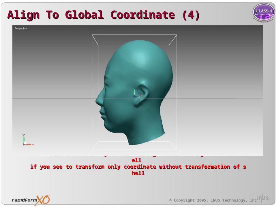
Align To Global Coordinate (4)Align To Global Coordinate (4)
13. Finally, Align to Model Coordinate from Model Coordinate13. Finally, Align to Model Coordinate from Model Coordinate※ Bind Reference Entity to shell using “ Ref.Geometry > Bind To Shell”※ Bind Reference Entity to shell using “ Ref.Geometry > Bind To Shell”if you see to transform only coordinate without transformation of shellif you see to transform only coordinate without transformation of shell

© Copyright 2005, INUS Technology, Inc.
Head Measurement (Position 01)Head Measurement (Position 01)
Method >Method > 1. Create 1. Create Normal PlaneNormal Plane form the Coordinate form the Coordinate using using “Ref.Geometry > Create > Plane > Input Normal & Position”“Ref.Geometry > Create > Plane > Input Normal & Position”
2. Create 2. Create Slice CurveSlice Curve from Normal Plane from Normal Plane
3. Measure 3. Measure the length of curvethe length of curve using using “Information > Curve”“Information > Curve”
Position Position 0101
End Point of End Point of CurveCurve
End Point of End Point of CurveCurve

© Copyright 2005, INUS Technology, Inc.
Head Measurement (Position 02)Head Measurement (Position 02)
Method >Method > 1. Create 1. Create Reference Point Reference Point on the surface of shell by Pick Pointon the surface of shell by Pick Point
2. Create 2. Create Projection PointProjection Point on Normal Plane (Normal Direction : Z Axis) From Reference Point on Normal Plane (Normal Direction : Z Axis) From Reference Point
2. Create 2. Create SectionSection Plane Plane usingusing thethe three of Point and Create three of Point and Create Slice CurveSlice Curve Form Section Plane. Form Section Plane.
3. Trim Interesting Region and Measure 3. Trim Interesting Region and Measure the length of curvethe length of curve using using “Information > Curve”“Information > Curve”
Position Position 0202
Reference Reference pointpoint
End Point of curve End Point of curve (Position 01)(Position 01)

© Copyright 2005, INUS Technology, Inc.
Head Measurement (Position 03)Head Measurement (Position 03)
Method >Method > 1. Create 1. Create Reference Point Reference Point on the surface of shell by Pick Pointon the surface of shell by Pick Point
2. Create 2. Create Normal Plane (Normal Direction : X Axis ) Normal Plane (Normal Direction : X Axis ) and Create and Create Parallel Plane Parallel Plane From Normal From Normal Plane using Plane using Normal Plane and Reference PointNormal Plane and Reference Point
2. Create 2. Create Slice CurveSlice Curve by Parallel Plane. by Parallel Plane.
3. Trim Interesting Region Measure 3. Trim Interesting Region Measure the length of curvethe length of curve using using “Information > Curve”“Information > Curve”
Position Position 0303
Reference Reference pointpoint

© Copyright 2005, INUS Technology, Inc.
Head Measurement (Position 04)Head Measurement (Position 04)
Method >Method > 1. Create 1. Create Reference Point Reference Point on the surface of shell by Pick Pointon the surface of shell by Pick Point
2. Create 2. Create Parallel Plane Parallel Plane From Normal Plane (Normal Direction : X Axis) using Normal Plane and From Normal Plane (Normal Direction : X Axis) using Normal Plane and Reference PointReference Point
2. Create 2. Create Slice CurveSlice Curve by Parallel Plane. by Parallel Plane.
3. Trim Interesting Region Measure 3. Trim Interesting Region Measure the length of curvethe length of curve using using “Information > Curve”“Information > Curve”
Position Position 0404
Reference Reference pointpoint

© Copyright 2005, INUS Technology, Inc.
Head Measurement (Position 05)Head Measurement (Position 05)
Method >Method > 1. Create 1. Create Reference Point Reference Point on the surface of shell by Pick Pointon the surface of shell by Pick Point
2. Create 2. Create Normal Plane (Normal Direction : Y Axis ) Normal Plane (Normal Direction : Y Axis ) and Create and Create Parallel Plane Parallel Plane From Normal From Normal Plane using Plane using Normal Plane and Reference PointNormal Plane and Reference Point
2. Create 2. Create Slice CurveSlice Curve by Parallel Plane. by Parallel Plane.
3. Trim Interesting Region Measure 3. Trim Interesting Region Measure the length of curvethe length of curve using using “Information > Curve”“Information > Curve”
Position Position 0505
Reference Reference pointpoint
© Copyright 2005, INUS Technology, Inc.
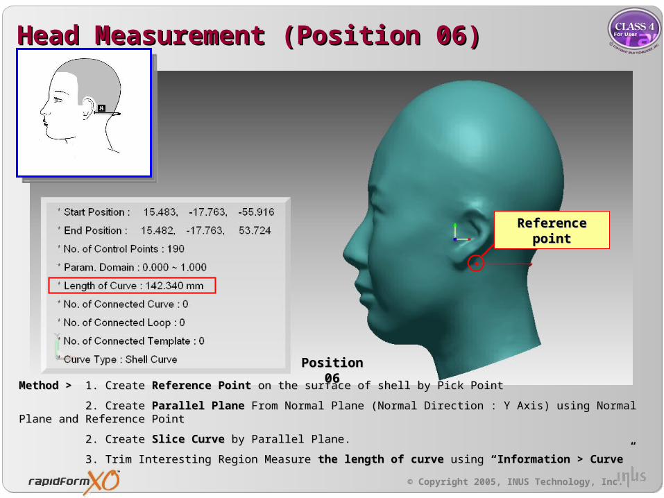
Head Measurement (Position 06)Head Measurement (Position 06)
Method >Method > 1. Create 1. Create Reference Point Reference Point on the surface of shell by Pick Pointon the surface of shell by Pick Point
2. Create 2. Create Parallel Plane Parallel Plane From Normal Plane (Normal Direction : Y Axis) using Normal Plane and From Normal Plane (Normal Direction : Y Axis) using Normal Plane and Reference PointReference Point
2. Create 2. Create Slice CurveSlice Curve by Parallel Plane. by Parallel Plane.
3. Trim Interesting Region Measure 3. Trim Interesting Region Measure the length of curvethe length of curve using using “Information > Curve”“Information > Curve”
Position Position 0606
Reference Reference pointpoint

© Copyright 2005, INUS Technology, Inc.
Head Measurement (Position 06)Head Measurement (Position 06)
Method >Method > 1. Create Projection Point on the Normal Plane (Normal Direction : Z Axis) form Ref.Point of Position 04 and 1. Create Projection Point on the Normal Plane (Normal Direction : Z Axis) form Ref.Point of Position 04 and CreatCreate e Section Plane Section Plane using Ref.Points (Position 04, Projected Point and Position 05). using Ref.Points (Position 04, Projected Point and Position 05).
2. Create 2. Create Slice CurveSlice Curve by Section Plane. by Section Plane.
3. Create Projection Point on the Normal Plane (Normal Direction : Z Axis) form Ref.Point of Position 05 and 3. Create Projection Point on the Normal Plane (Normal Direction : Z Axis) form Ref.Point of Position 05 and CreatCreate e Section Plane Section Plane using Ref.Points (Position 05, Projected Point and the End Point of Curve (Position 01)). using Ref.Points (Position 05, Projected Point and the End Point of Curve (Position 01)).
4. Create 4. Create Slice CurveSlice Curve by Section Plane. by Section Plane.
5. Trim the couple of Slice Curve using 5. Trim the couple of Slice Curve using “Curve > Trim > Curve / Curve”“Curve > Trim > Curve / Curve”. .
6. Trim Interesting Region Measure 6. Trim Interesting Region Measure the length of curvethe length of curve using using “Information > Curve”“Information > Curve”
Reference pointReference point
Position Position 0606
End Point of End Point of CurveCurve