analyze & assess integrated and self-consistent ife chamber concepts understand trade-offs and...
Post on 22-Dec-2015
214 views
TRANSCRIPT

Analyze & assess integrated and self-consistent IFE chamber concepts
Understand trade-offs and identify design windows for promising concepts. The research is not aimed at developing a point design.
Identify existing data base and extrapolations needed for each promising concept. Identify high-leverage items for R&D:
• What data is missing? What are the shortcomings of present tools?
• For incomplete database, what is being assumed and why?
• For incomplete database, what is the acceptable range of data? Would it make a difference to zeroth order, i.e., does it make or break the concept?
• Start defining needed experiments and simulation tools.
ARIES Integrated IFE Chamber Analysis and Assessment Research -- Goals

ARIES-IFE Is a Multi-institutional Effort
Program ManagementF. Najmabadi
Les Waganer (Operations)
Mark Tillack (System Integration)
Program ManagementF. Najmabadi
Les Waganer (Operations)
Mark Tillack (System Integration)Advisory/Review
Committees
Advisory/Review
Committees
OFESOFESExecutive Committee
(Task Leaders)
Executive Committee
(Task Leaders)
Fusion
Labs
Fusion
Labs
• Target Fab. (GA, LANL*)
• Target Inj./Tracking (GA)
• Chamber Physics (UW, UCSD)
• Chamber Eng. (UCSD, UW)
• Parametric Systems Analysis (UCSD, BA, LLNL)
• Materials (ANL)
• Target Physics (NRL*, LLNL*, UW)
• Drivers* (NRL*, LLNL*, LBL*)
• Final Optics & Transport
(UCSD, LBL , PPPL, MIT, NRL*,LLNL*)
• Safety & Env. (INEEL, UW, LLNL)
• Tritium (ANL, LANL*)
• Neutronics, Shielding (UW, LLNL)
Tasks
* voluntary contributions
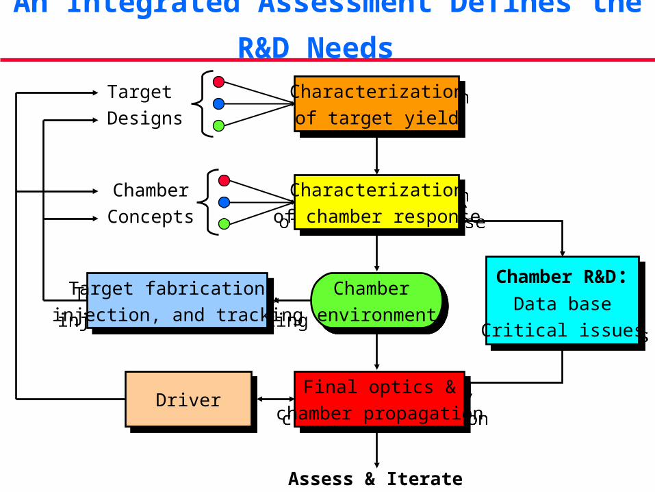
An Integrated Assessment Defines the R&D Needs
Characterization
of target yield
Characterization
of target yield
Target
Designs
Chamber
ConceptsCharacterization
of chamber response
Characterization
of chamber response
Chamber
environment
Chamber
environment
Final optics &
chamber propagation
Final optics &
chamber propagation
Chamber R&D:Data base
Critical issues
Chamber R&D:Data base
Critical issues
DriverDriver
Target fabrication,
injection, and tracking
Target fabrication,
injection, and tracking
Assess & Iterate

We Use a Structured Approach to Asses Driver/Chamber Combinations
To make progress, we divided the activity based on three classes of chambers:• Dry wall chambers;• Solid wall chambers protected with a “sacrificial zone” (such
as liquid films); • Thick liquid walls.
We plan to research these classes of chambers in series with the entire team focusing on each.
While the initial effort is focused on dry walls, some of the work is generic to all concepts (e.g., characterization of target yield, target injection and tracking, etc).

Status of ARIES-IFE Study
Six classes of target were identified. Advanced target designs from NRL (laser-driven direct drive) and LLNL (Heavy-ion-driven indirect-drive) are used as references.
Detailed output spectrum from these targets are calculated and used for analysis of other systems.
Analysis of design window for successful injection of direct and indirect drive targets in a gas-filled chamber (e.g., Xe) is completed.
Final focus and transport is under study:
• Grazing incident metal mirrors for lasers.
• Focusing magnets for heavy ions and beam transport in a “high-pressure” chamber.
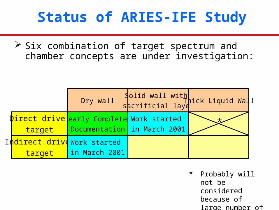
Status of ARIES-IFE Study
Six combination of target spectrum and chamber concepts are under investigation:
Nearly Complete,
Documentation
Direct drive
target
Work started
in March 2001
Dry wallSolid wall with
sacrificial layerThick Liquid Wall
Indirect drive
target
Work started
in March 2001
* Probably will not be considered because of large number of penetrations needed
*

Backup Material

Reference Direct and Indirect Target Designs
NRL Advanced Direct-Drive Targets
DT Vapor0.3 mg/cc
DT Fuel
CH Foam + DT
1 m CH +300 Å Au
.195 cm
.150 cm
.169 cm
CH foam = 20 mg/cc
DT Vapor0.3 mg/cc
DT Fuel
CH Foam + DT
5 CH
.122 cm
.144 cm
.162 cm
CH foam = 75 mg/cc
1
10
100
1000
0 5 10 15time (ns)
laser power •NRL Direct Drive Target Gain Calculations (1-D) have been corroborated by LLNL and UW.
LLNL/LBNL HIF Target

Energy output and X-ray Spectra from Reference Direct and Indirect Target Designs
NRL Direct Drive Target (MJ)
HI Indirect Drive Target (MJ)
X-rays 2.14 (1%) 115 (25%)
Neutrons 109 (71%) 316 (69%)
Gammas 0.0046 (0.003%) 0.36 (0.1%)
Burn product fast ions
18.1 (12%) 8.43 (2%)
Debris ions kinetic energy
24.9 (16%) 18.1 (4%)
Residual thermal energy
0.013 0.57
Total 154 458
X-ray spectrum is much harder
for NRL direct-drive target
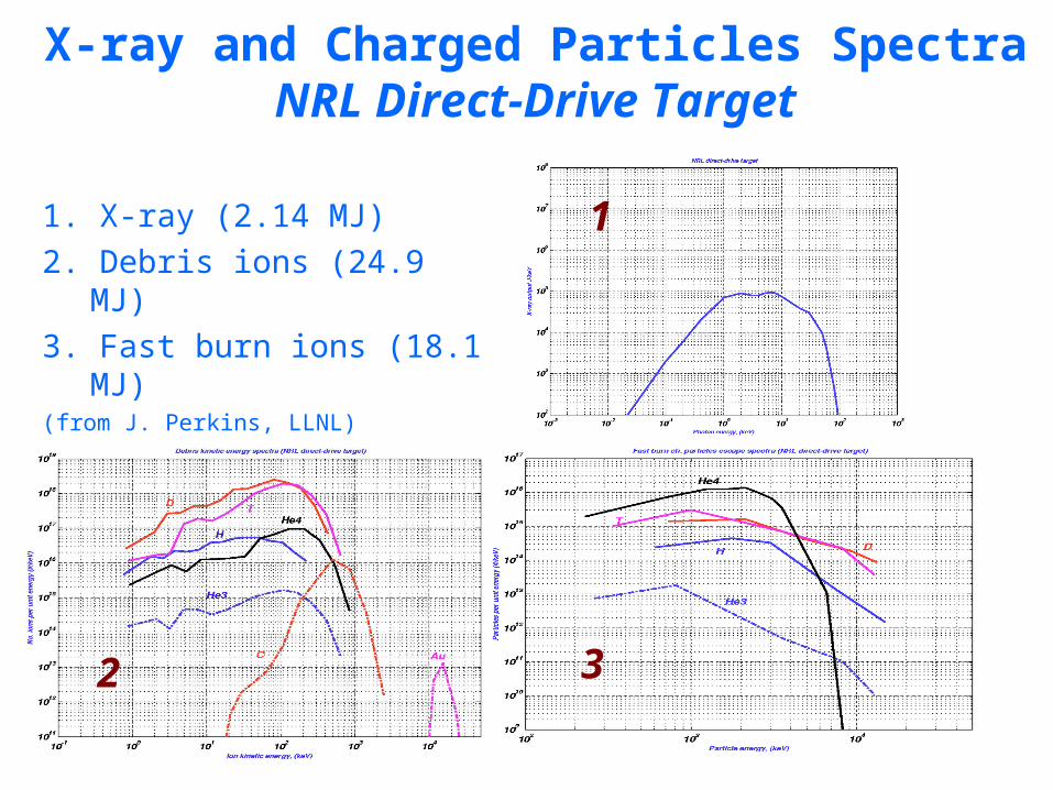
X-ray and Charged Particles SpectraNRL Direct-Drive Target
1. X-ray (2.14 MJ)
2. Debris ions (24.9 MJ)
3. Fast burn ions (18.1 MJ)(from J. Perkins, LLNL)
3
1
2

Ion Spectra from Reference HI-Driven Indirect –Drive Target
Slow Ions
Fast Ions

• 1992 Sombrero Study highlighted many advantages of dry wall chambers.
• General Atomic calculations indicated that direct-drive targets do not survive injection in Sombrero chamber.
A Year Ago, Feasibility of Dry Wall Chambers Was in Question

Target injection Design Window Naturally Leads to Certain Research Directions
Chamber-based solutions:Low wall temperature: Decoupling of first wall & blanket temperaturesLow gas pressure: More accurate calculation of wall loading & response
Advanced engineered materialAlternate wall protection Magnetic diversion of ions*
Target-based solutions: Sabot or wake shield, Frost coating* * Not considered in detail
Target injection window
(for 6-m Xe-filled chambers):
Pressure < 10-50 mTorr
Temperature < 700 C
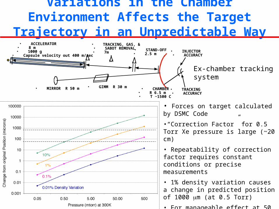
Variations in the Chamber Environment Affects the Target Trajectory in an Unpredictable Way
• Forces on target calculated by DSMC Code
•“Correction Factor” for 0.5 Torr Xe pressure is large (~20 cm)
• Repeatability of correction factor requires constant conditions or precise measurements
• 1% density variation causes a change in predicted position of 1000 m (at 0.5 Torr)
• For manageable effect at 50 mTorr, density variability must be <0.01%.
• Leads to in-chamber tracking
Ex-chamber tracking system
• MIRROR R 50 m
• TRACKING, GAS, &• SABOT REMOVAL • 7m
• STAND-OFF • 2.5 m
• CHAMBER • R 6.5 m • T ~1500 C
• ACCELERATOR • 8 m • 1000 g • Capsule velocity out 400 m/sec
• INJECTOR • ACCURACY
• TRACKING • ACCURACY
• GIMM R 30 m
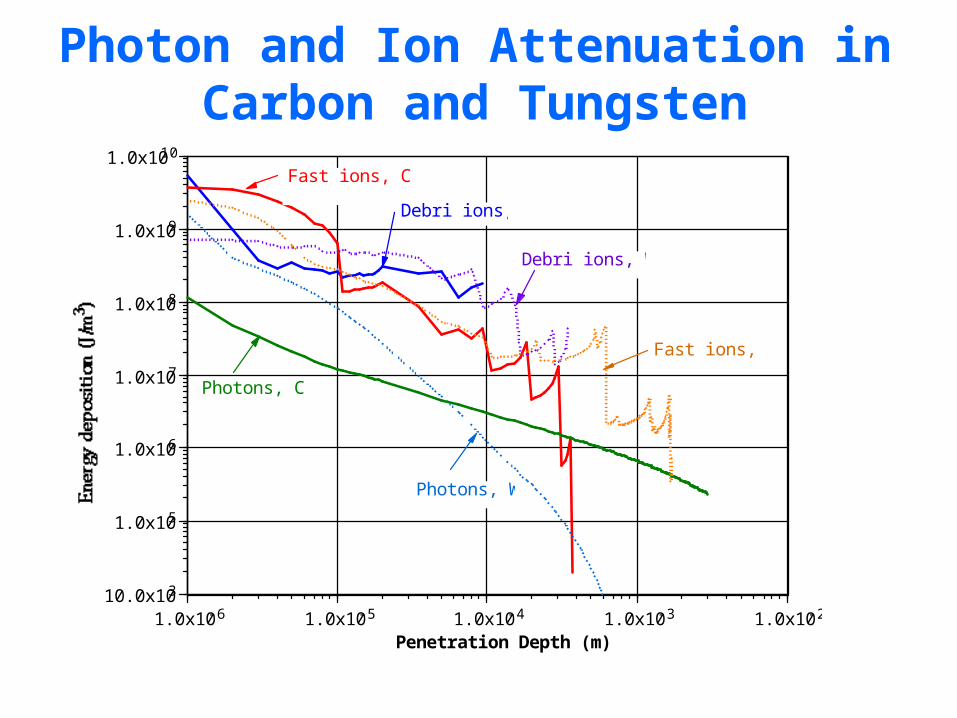
Photon and Ion Attenuation in Carbon and Tungsten
10.0x10³
1.0x10⁵
1.0x10⁶
1.0x10⁷
1.0x10⁸
1.0x10⁹
1.0x10¹⁰
1.0x10⁻⁶ 1.0x10⁻⁵ 1.0x10⁻⁴ 1.0x10⁻³ 1.0x10⁻²
Penetration Depth (m)
Photons, C
Photons, W
Fast ions, C
Fast ions, W
Debri ions, C
Debri ions, W
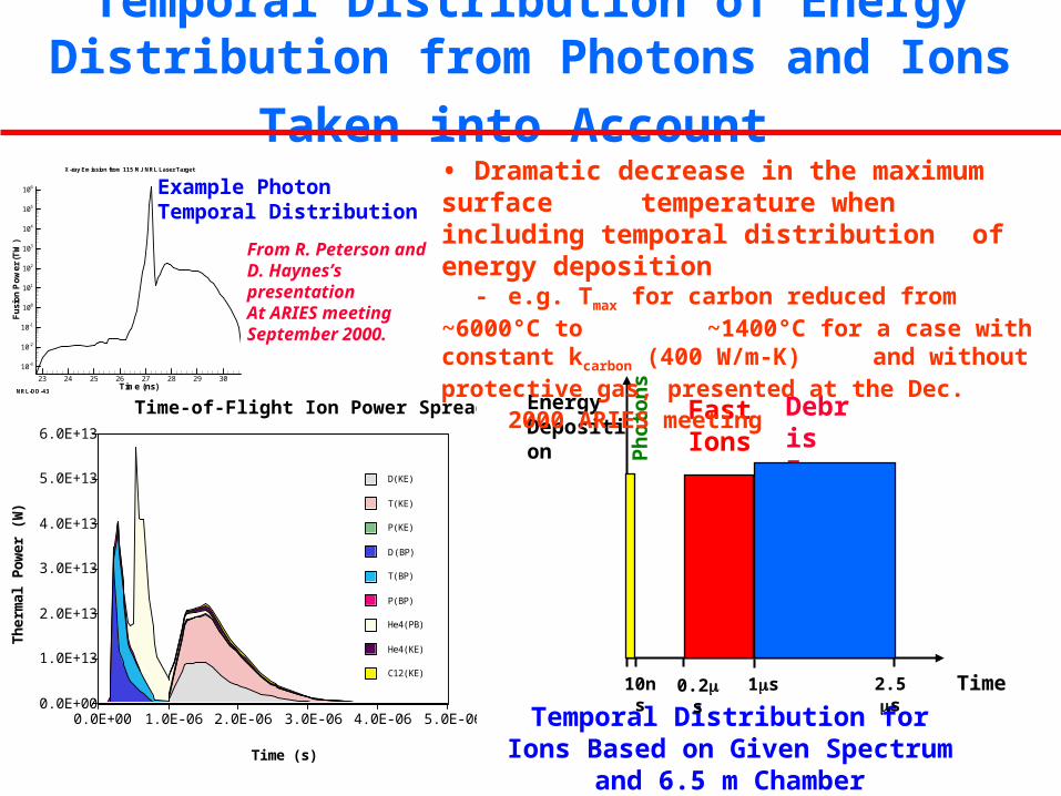
Temporal Distribution of Energy Distribution from
Photons and Ions Taken into Account
Time (ns)
Fu
sio
nP
ow
er
(TW
)
23 24 25 26 27 28 29 30
10-3
10-2
10-1
100
101
102
103
104
105
106
NRL-DD-43
X-ray Emission from 115 MJ NRL Laser Target
From R. Peterson and D. Haynes’s presentation At ARIES meeting September 2000.
Example Photon Temporal Distribution
Temporal Distribution for Ions Based on Given Spectrum and 6.5 m Chamber
0.0E+00
1.0E+13
2.0E+13
3.0E+13
4.0E+13
5.0E+13
6.0E+13
Th
erm
al P
ower
(W
)
0.0E+00 1.0E-06 2.0E-06 3.0E-06 4.0E-06 5.0E-06
Time (s)
Time-of-Flight Ion Power Spread
C12(KE)
He4(KE)
He4(PB)
P(BP)
T(BP)
D(BP)
P(KE)
T(KE)
D(KE)
Debris Ions
Time10ns 0.2s 1s 2.5s
FastIonsP
hot
onsEnergy
Deposition
• Dramatic decrease in the maximum surface temperature when including temporal distribution of energy deposition- e.g. Tmax for carbon reduced from ~6000°C to ~1400°C for a case with constant kcarbon (400 W/m-K) and without protective gas, presented at the Dec. 2000 ARIES meeting

Example Temperature History for Carbon Flat Wall Under Energy Deposition from NRL Direct-
Drive Spectra• Coolant temperature = 500°C
• Chamber radius = 6.5 m
• Maximum temperature = 1530 °C
• Sublimation loss per year = 3x10-13 m (availability=0.85)
Coolant at 500°C3-mm thick Carbon Chamber Wall
EnergyFront
Evaporation heat flux B.C at incident wall
Convection B.C. at coolant wall:h= 10 kW/m2-K
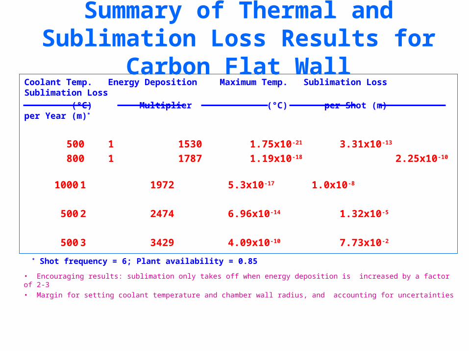
Summary of Thermal and Sublimation Loss Results for Carbon Flat Wall
Coolant Temp. Energy Deposition Maximum Temp. Sublimation Loss Sublimation Loss
(°C) Multiplier (°C) per Shot (m) per Year (m)*
500 1 1530 1.75x10⁻²¹ 3.31x10⁻¹³
800 1 1787 1.19x10⁻¹⁸ 2.25x10⁻¹⁰
1000 1 1972 5.3x10⁻¹⁷ 1.0x10⁻⁸
500 2 2474 6.96x10⁻¹⁴ 1.32x10⁻⁵
500 3 3429 4.09x10⁻¹⁰ 7.73x10⁻²
* Shot frequency = 6; Plant availability = 0.85
• Encouraging results: sublimation only takes off when energy deposition is increased by a factor of 2-3
• Margin for setting coolant temperature and chamber wall radius, and accounting for uncertainties
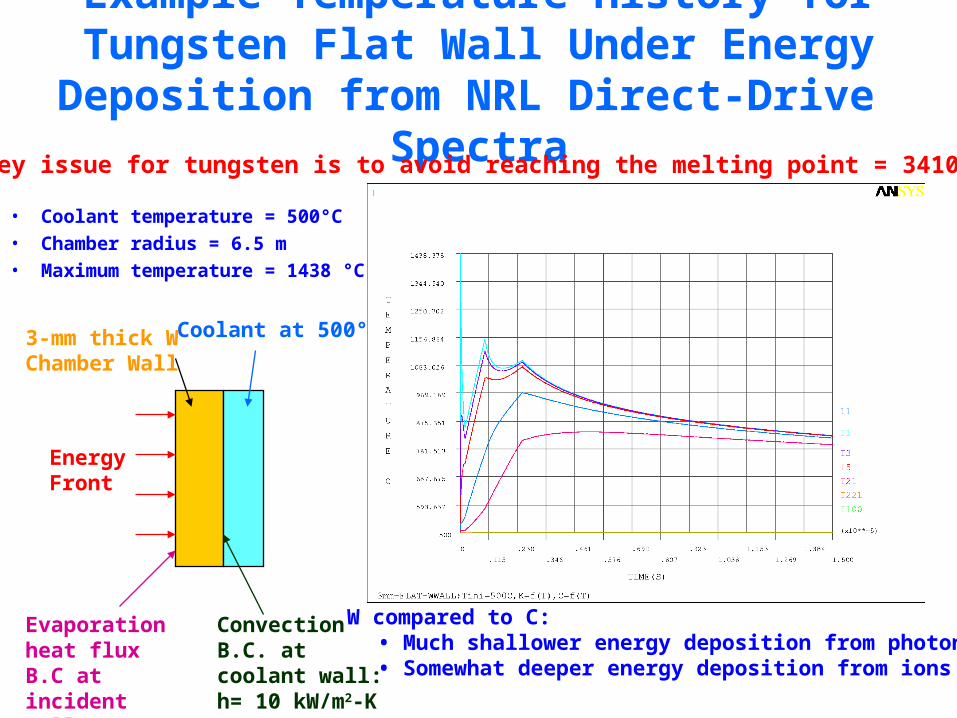
Example Temperature History for Tungsten Flat Wall Under Energy Deposition from NRL Direct-
Drive Spectra
• Coolant temperature = 500°C• Chamber radius = 6.5 m• Maximum temperature = 1438 °C
Coolant at 500°C3-mm thick W Chamber Wall
EnergyFront
Evaporation heat flux B.C at incident wall
Convection B.C. at coolant wall:h= 10 kW/m2-K
Key issue for tungsten is to avoid reaching the melting point = 3410°C
W compared to C:• Much shallower energy deposition from photons • Somewhat deeper energy deposition from ions

Example Temperature History for Tungsten Flat Wall Under 5 x Energy Deposition from
NRL Direct-Drive Spectra• Illustrate melting process from W; melting point = 3410°C• Include phase change in ANSYS by increasing enthalpy at melting point to
account for latent heat of fusion (= 220 kJ/kg for W)• Melt layer thickness ~ 1.2 m Separation = 1 m
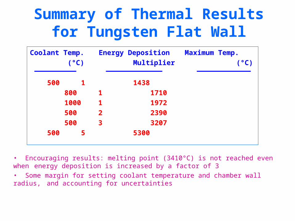
Summary of Thermal Results for Tungsten Flat Wall
Coolant Temp. Energy Deposition Maximum Temp.
(°C) Multiplier (°C)
500 1 1438
800 1 1710
1000 1 1972
500 2 2390
500 3 3207
500 5 5300
• Encouraging results: melting point (3410°C) is not reached even when energy deposition is increased by a factor of 3
• Some margin for setting coolant temperature and chamber wall radius, and accounting for uncertainties
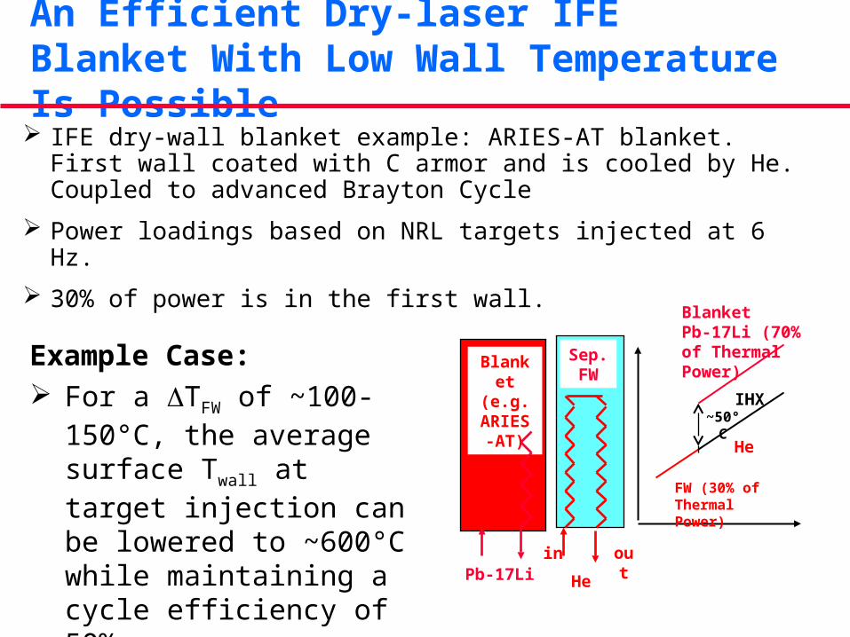
An Efficient Dry-laser IFE Blanket With Low Wall Temperature Is Possible IFE dry-wall blanket example: ARIES-AT blanket. First wall
coated with C armor and is cooled by He. Coupled to advanced Brayton Cycle
Power loadings based on NRL targets injected at 6 Hz.
30% of power is in the first wall.
Blanket(e.g.
ARIES-AT)
Sep.FW
Pb-17Lioutin
He
BlanketPb-17Li (70% of Thermal Power)
He
FW (30% of Thermal Power)
~50°CIHX
Example Case: For a TFW of ~100-150°C, the
average surface Twall at target injection can be lowered to ~600°C while maintaining a cycle efficiency of 50%

Initial Results from ARIES-IFE have Removed Major Feasibility Issues of Dry Wall Chambers
Research is now focused on Optimization And Attractiveness
Trade-off studies are continuing to fully characterize the design window. We are analyzing response of the chamber to Higher target yields Smaller chamber sizes Different chamber wall armor
Un-going activities in: Engineered Material, Effect of chamber environment on target trajectory Final optics Safety

• Good parallel heat transfer, compliant to thermal shock
• Tailorable fiber geometry, composition, matrix
• Already demonstrated for high-power laser beam dumps and ion erosion tests
• Fibers can be thinner than the x-ray attenuation length.
Advanced Engineered Materials May Provide
Superior Damage Resistance
Carbon fiber velvet in carbonizable substrate 7–10 m fiber diameter1.5-2.5-mm length1-2% packing fraction
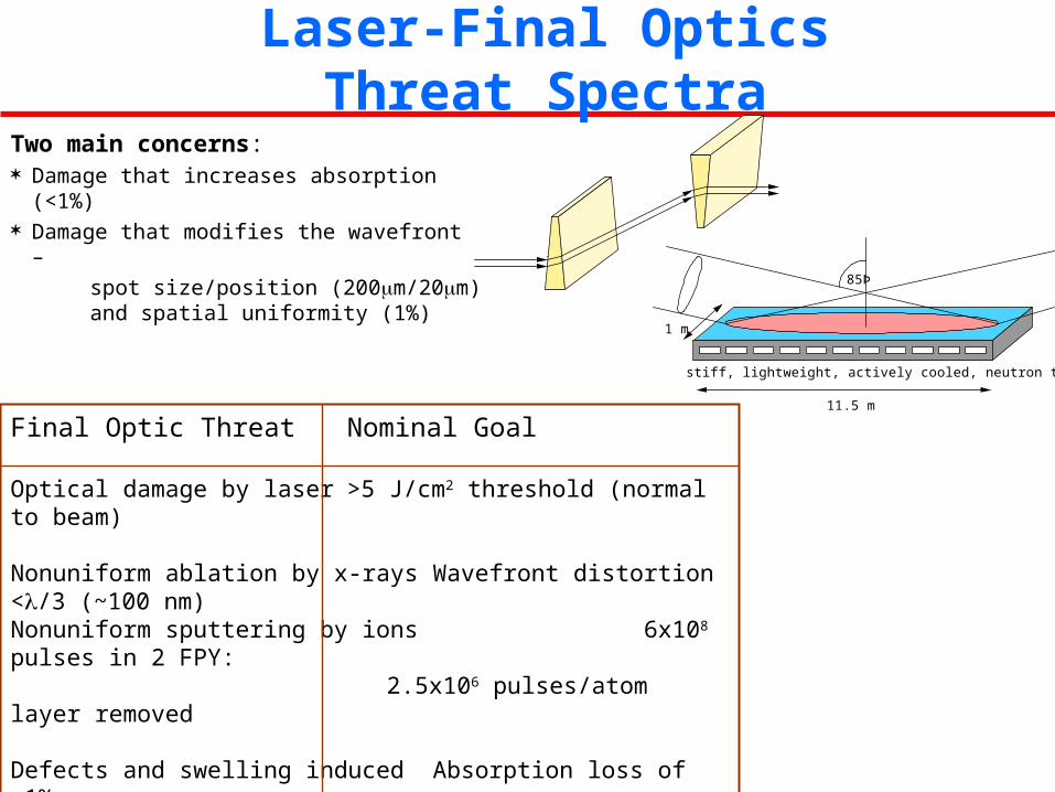
Laser-Final Optics Threat Spectra
Final Optic Threat Nominal Goal
Optical damage by laser >5 J/cm2 threshold (normal to beam)
Nonuniform ablation by x-rays Wavefront distortion </3 (~100 nm)Nonuniform sputtering by ions 6x10⁸ pulses in 2 FPY:
2.5x10⁶ pulses/atom layer removed
Defects and swelling induced Absorption loss of <1%by -rays and neutrons Wavefront distortion of < /3
Contamination from condensable Absorption loss of <1%materials (aerosol, dust, etc.) >5 J/cm2 threshold
Two main concerns: Damage that increases absorption (<1%) Damage that modifies the wavefront –
spot size/position (200m/20m) and spatial uniformity (1%)
85Þ
stiff, lightweight, actively cooled, neutron transparent substrate
1 m
11.5 m
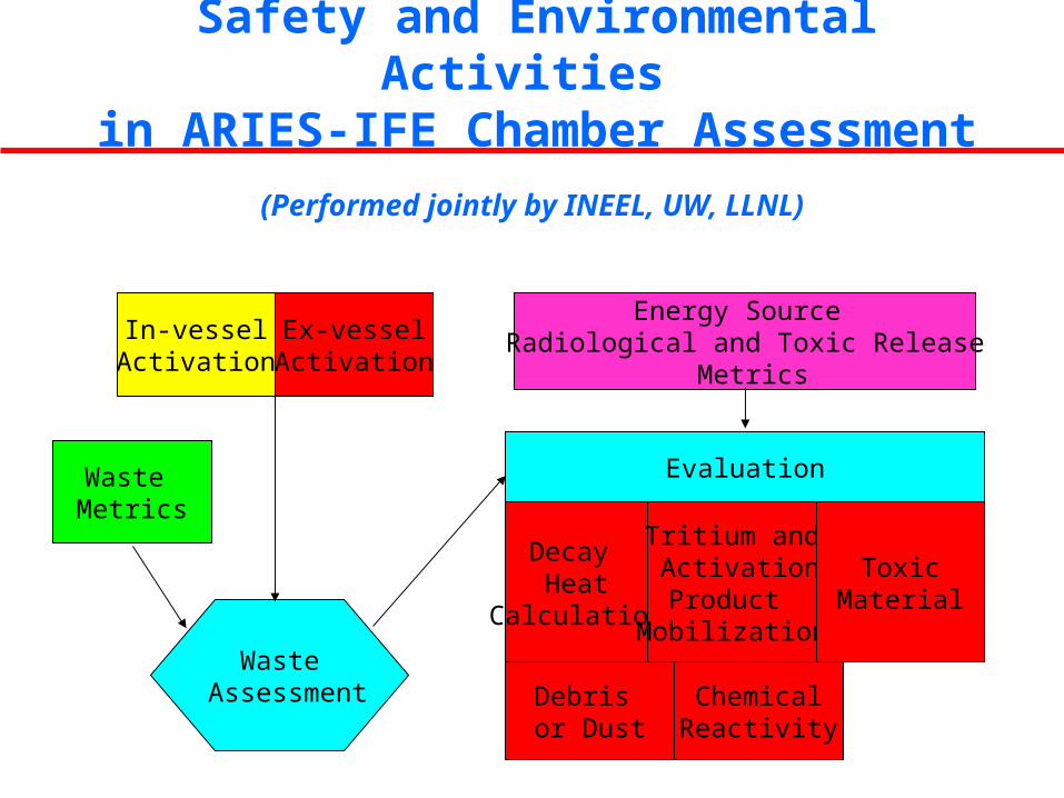
Safety and Environmental Activities in ARIES-IFE Chamber Assessment
In-vesselActivation
Ex-vesselActivation
Waste Assessment
Waste Metrics
Energy Source Radiological and Toxic Release
Metrics
Evaluation
Decay Heat
Calculation
Tritium and ActivationProduct
Mobilization
Debris or Dust
ChemicalReactivity
ToxicMaterial
(Performed jointly by INEEL, UW, LLNL)