© abb group september 4, 2015 | slide 1 thermowell calculation guide in accordance with asme ptc...
TRANSCRIPT

© ABB Group April 19, 2023 | Slide 1
Thermowell Calculation GuideIn accordance with ASME PTC 19.3 TW-2010
Andrew Dunbabin March 2012
© ABB Group April 19, 2023 | Slide 2
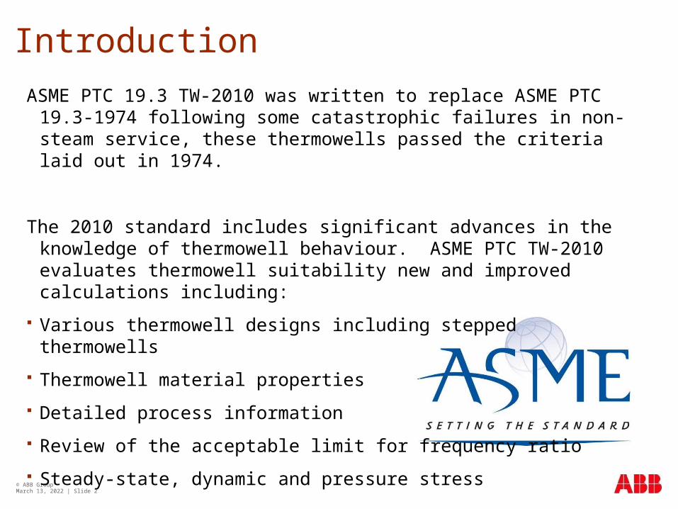
Introduction
ASME PTC 19.3 TW-2010 was written to replace ASME PTC 19.3-1974 following some catastrophic failures in non-steam service, these thermowells passed the criteria laid out in 1974.
The 2010 standard includes significant advances in the knowledge of thermowell behaviour. ASME PTC TW-2010 evaluates thermowell suitability new and improved calculations including:
Various thermowell designs including stepped thermowells
Thermowell material properties
Detailed process information
Review of the acceptable limit for frequency ratio
Steady-state, dynamic and pressure stress

Failure of a thermowell
© ABB Group April 19, 2023 | Slide 3
In 1995 a thermowell failed in the secondary coolant loop of the Monju fast breeder reactor in Japan.
The failure closed the plant for 15 years
The thermowell was designed to ASME PTC 19.3 1974
The failure was found to be due to the drag resonance induced on the thermowell by the liquid sodium coolant

© ABB Group April 19, 2023 | Slide 4
Stresses on a Thermowell
Thermowells protect temperature sensors from direct contact with a process fluid. But once inserted into the process, the thermowell can obstruct flow around it, leading to a drop in pressure. This phenomenon creates low pressure vortices downstream of the thermowell.
These vortices occur at one side of the thermowell and then the other, which is known as alternating vortex shedding. This effect can be seen in the example of a flag pole rippling a flag in the wind
© ABB Group April 19, 2023 | Slide 5
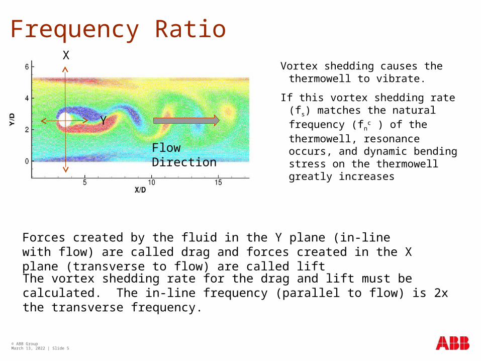
Frequency Ratio
Vortex shedding causes the thermowell to vibrate.
If this vortex shedding rate (fs) matches the natural frequency (fn
c ) of the thermowell, resonance occurs, and dynamic bending stress on the thermowell greatly increases
The vortex shedding rate for the drag and lift must be calculated. The in-line frequency (parallel to flow) is 2x the transverse frequency.
Forces created by the fluid in the Y plane (in-line with flow) are called drag and forces created in the X plane (transverse to flow) are called lift
X
Y
Flow Direction

Induced Frequencies
Where the induced frequency meets the natural frequency of the thermowell the amplitude of vibration increases rapidly
The drag frequency induced is twice that of the lift frequency induced.
As such it meets the natural frequency of the thermowell at half the fluid velocity of the lift induced frequency
The drag forces are smaller than the lift forces and under certain special conditions may not be significant.
© ABB Group April 19, 2023 | Slide 6

Resonance “lock in”
Both lift and drag resonance tends to “lock in” on the natural frequency
The low damping of thermowells exaggerates this effect
© ABB Group April 19, 2023 | Slide 7
Fn
Nominal lock-in range
In line (drag) excitationTransverse (lift)
Fluid velocity
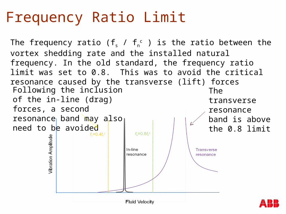
Frequency Ratio Limit
The frequency ratio (fs / fnc ) is the ratio between the vortex shedding rate and the
installed natural frequency. In the old standard, the frequency ratio limit was set to 0.8. This was to avoid the critical resonance caused by the transverse (lift) forces
The transverse resonance band is above the 0.8 limit
Following the inclusion of the in-line (drag) forces, a second resonance band may also need to be avoided
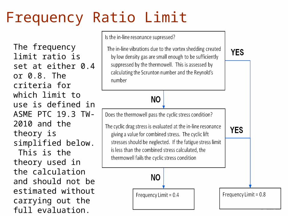
Frequency Ratio Limit
The frequency limit ratio is set at either 0.4 or 0.8. The criteria for which limit to use is defined in ASME PTC 19.3 TW-2010 and the theory is simplified below. This is the theory used in the calculation and should not be estimated without carrying out the full evaluation.
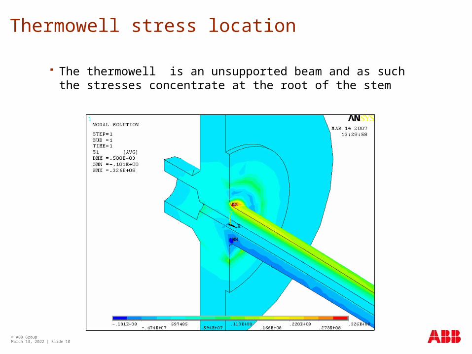
Thermowell stress location
The thermowell is an unsupported beam and as such the stresses concentrate at the root of the stem
© ABB Group April 19, 2023 | Slide 10

Thermowells; when to perform a calculation
A thermowell can be considered to be at negligible risk if the following criteria are met:
Process fluid velocity is less than 0.64 m/s
Wall thickness is 9.55 mm or more
Unsupported length is 610 mm or less
Root and tip diameter are 12.7 mm or more
Maximum allowable stress is 69 Mpa or more
Fatigue endurance limit is 21 Mpa or more
For all other conditions it is advised that a calculation is performed
© ABB Group April 19, 2023 | Slide 11
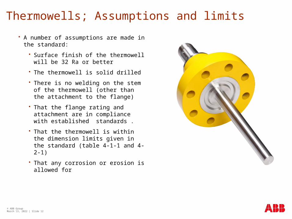
Thermowells; Assumptions and limits
A number of assumptions are made in the standard:
Surface finish of the thermowell will be 32 Ra or better
The thermowell is solid drilled
There is no welding on the stem of the thermowell (other than the attachment to the flange)
That the flange rating and attachment are in compliance with established standards .
That the thermowell is within the dimension limits given in the standard (table 4-1-1 and 4-2-1)
That any corrosion or erosion is allowed for
© ABB Group April 19, 2023 | Slide 12

Thermowell; the pass criteria
There are four criteria for a thermowell to pass evaluation to PTC 19.3 TW-2010
Frequency limit: the resonance frequency of the thermowell shall be sufficiently high so that destructive oscillations are not excited by the fluid flow
Dynamic stress limit: the maximum primary dynamic stress shall not exceed the allowable fatigue stress limit
Static stress limit: the maximum steady-state stress on the thermowell shall not exceed the allowable stress, determined by the Von Mises criteria
Hydrostatic pressure limit: the external pressure shall not exceed the pressure ratings of the thermowell tip, shank and flange
All four of the criteria need to be evaluated and all four need to be passed.
© ABB Group April 19, 2023 | Slide 13
© ABB Group April 19, 2023 | Slide 14
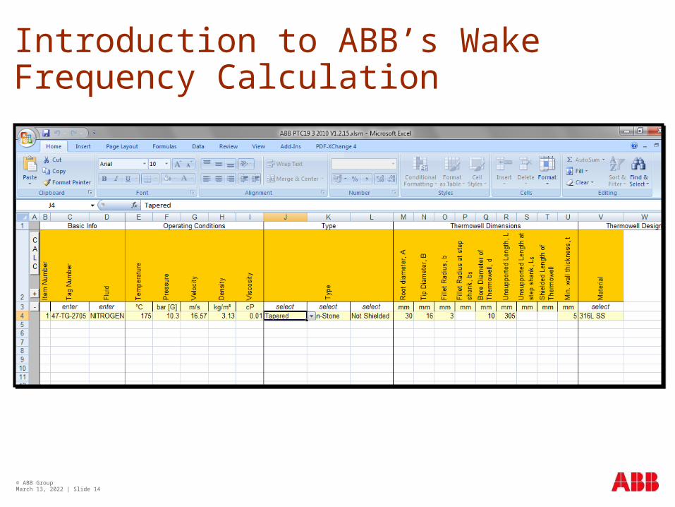
Introduction to ABB’s Wake Frequency Calculation

© ABB Group April 19, 2023 | Slide 15
Thermowell Types
STR/THREAD STR/SW STR/FLG STR/VAN STR/WELD
TAP/THREAD TAP/SW TAP/FLG TAP/VAN TAP/WELD
STEP/THREAD STEP/SW STEP/FLG STEP/VAN STEP/WELD
KEY: STR = STRAIGHT; TAP = TAPERED; STEP = STEPPED
THREAD = THREADED; SW = SOCKET WELD; FLG = FLANGED;
VAN = VAN STONE; WELD = WELD-IN
© ABB Group April 19, 2023 | Slide 16
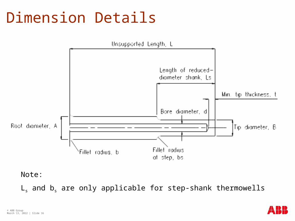
Dimension Details
Note:
Ls and bs are only applicable for step-shank thermowells

© ABB Group April 19, 2023 | Slide 17
Calculation Report
Project and client details from the Front Page are shown here
Input data from the Data Entry sheet is pulled through here including the thermowell type and material details
The calculated results are shown in either Metric or Imperial units as selected on the Front Page
Thermowell Suitability is the key information
The reason for suitability failure can be found in the comments section

© ABB Group April 19, 2023 | Slide 18
When a Calculation Fails
If a thermowell fails the evaluation, the design can be changed in the following ways:
• Shorten the thermowell to reduce the unsupported length
• Increase the thickness of the thermowell (A and B)
A velocity collar can be added to reduce the unsupported length although this is not generally recommended. A velocity collar is used to provide a rigid support to the thermowell and will work only if there is an interference fit between the standoff wall and the collar.
Care must be taken to ensure the collar meets the standoff wall at installation and is not affected by corrosion. If a velocity collar is the only viable solution, it is the responsibility of the operator to ensure there is an interference fit between the standoff wall and the velocity collar.

© ABB Group April 19, 2023 | Slide 19