· a controlnet physical network is comprised of this cable and a combination of connecting,...
TRANSCRIPT

� � � �������� � ��� ��
�� �������� �������
This chapter introduces the ControlNet network. It contains thesesections:
�� �� ���
���� #"'%# ��'� ��'*#%�� ��&&�#" �
���� #"'%# ��'� ��'*#%�� �&� �� ��%'� #�� �"� � �",�%�� �+� �%���'��'(%� �
�����'� �#�� �"� �
���� #"'%# ��'� #!!("���'�#"� �#�� �
#"'%# ��'� �%#�(�'� �)�%)��*
#"'%# ��'� �"�� �%&
#"'%# ��'� ����� ��
The ControlNet network’s mission is to provide reliable, high-speedtransport of two basic types of application information:
• control and I/O data
• non-time critical messaging data related to the controlled system
Control and I/O data are given highest priority. Other information,such as programming or parameter upload and download operations,does not interfere with the transport of control and I/O data.
The ControlNet network:
• provides a high-speed control and I/O network
• facilitates deterministic data transfer over the network
• supports transparent media redundancy (optional)
• combines the functions of RIO and DH+ networks into a singleLAN
• supports easy configuration, maintenance, and troubleshooting
��� ���������� ������� �� ��
#"'%# � �"�� ���� ��'�� �&�"�#%!�'�#"� �%�'��� � '#� '��#$�%�'�#"� #�� �� $%#��&&�

2 An Introduction to the ControlNet Network
The ControlNet network is designed to be the central communicationarchitecture for interoperating automation products. Figure 1.1represents the ControlNet network’s broad environment.
������ �������������! ����� ������������
)'($"�&� �$'(� $"%)(�&
�)"�#�#(�&����'
�)!( ���#�$&��* ��'
�(�+�-'
�& *�'�)"�& ��!$#(&$!
��!�$#(&$!
��'�%�&�($&�#(�&����'
��'' '
��'
��#'$&���()�($& � #�!�� �$ #(� �����#'$&���()�($& � #�!�� �$ #(� ���
�������� ��������
�!�,����
�������� ��������
����� ���
& ���'�
��������� ���������
��������
�(��&�)($"�( $#
�)%%! �&'��&$�)�('
�#(�!! ��#(��#'$&���()�($&
��� ���
���� ���������� ������� ���� ����� ��� ��� �����!������ ������������

3An Introduction to the ControlNet Network
The ControlNet network is designed through object modeling.Object modeling organizes related data and procedures into oneentity: the object.
An object is a collection of related services and attributes. Servicesare procedures an object performs. Attributes are characteristics ofobjects represented by values, which can vary. Typically, attributesprovide status information or govern the operation of an object.Attributes often represent the state of an object. The valueassociated with an attribute may or may not affect the behavior of anobject. An object’s behavior is an indication of how the objectresponds to particular events.
Classes categorize objects. A class defines a particular type ofobject and defines the characteristics shared by all the objects withina class. For example, the human race could be represented by theclass “Human” with millions of objects within it.
Objects within a class are called object instances. An object instanceis the actual representation of a particular object within a class. Eachinstance of a class has the same set of attributes, but has its own setof attribute values, which makes each instance in the class unique.
Each person in the human race can be represented by an instancewithin the class “Human.” All humans have the same set ofattributes: eyes, ears, age, gender, etc. Yet, because the values ofeach attribute vary, each of us looks different and performs indistinct ways.
� ����� �������� ���������� ���������� ������
��� !&��% �����
�"���
��� !&��� ��
� �"���
����� ��% ����
����� ��� ��
Application objects communicate with each other by sendingmessages. As shown in Figure 1.2, messages can be sent betweenobjects within a single node and across networks.
������� ���������������� ������� ������� ����
�����!�����!�����! �����!
��
���
��
���
��
���
��������
����������
�� ��� � ���� ��$�� � � �� ���� ����$ �
�����!
������� �������
��!��� �!����
Objects
�� ����� � ��������!
�� �� ���� � � � ������ ��!� !�� �������!� !�� ���"� !�� ��#����

4 An Introduction to the ControlNet Network
General relationships between the functions that comprise theControlNet communication model are illustrated in Figure 1.3. All of the figure’s blocks below the User’s Application Objectsreside within either a ControlNet ASIC or ControlNet class-specificExample Code.
��&#�� �����! %#!� �%� �!��& ���%�! �!���
�$�#�$� �""����%�! � �����%$
������ ����$$� ��#'���$
� ����������� � � � � � ����
�� ������� �������
������������ � � ���� ��� � � � � ���� � � ������
�� �� ��)�#� �#�'�#
��)$����� ��)�#� %�#����
�������� ������ � �
� � � �������
����������� � � ���
�""����%�! �
�%(!#�
�#� $"!#% ��)�#
��)�#
��)�#
��)�#�� �
������ ����$$
������ � � ����)$����� ��)�#
���� ���� �����
�������� �������� ������ ��� � �
���� �! %#!� �%�!��& ���%�! � �!���

5An Introduction to the ControlNet Network
�������� ����� ����� ����������
This section provides a bottom-up definition of each of theControlNet Communication Model’s components illustrated inFigure 1.3, on page 4.
The Physical Layer Interface consists of the hardware componentswhich are necessary to get on and off the network’s physical media.It is responsible for:
• providing transceiver components for the redundant coax mediaports
• providing transceiver components for the Network Access Port(NAP)
Media Access Service allows an application to transmit on thenetwork’s media. This service is contained within the ControlNetASICs. It is responsible for:
• providing transmit and receive data flow-control on and off themedia
• checking received data for errors
• adding the proper header and trailer information on transmitframes
• deleting header and trailer information from received frames
• controlling the media redundancy switch-over algorithm
The Link Layer Driver assembles data into correctly-formattedControlNet frames and is responsible for:
• setting up the Media Access Service
• moving data to and from the Media Access Service
• controlling the Media Access Service’s transmit and receive dataflow
• holding received data in temporary storage until checked forerrors by the Media Access Service
The Unconnected Message Manager (UCMM) provides the abilityto send a message without an established connection. It isresponsible for:
• receiving incoming UCMM messages
• sending and receiving unconnected messages to and from UCMMobjects on other nodes
• sending and receiving unconnected messages to and from its localMessage Router
� ��� �� � ��� ������ ��
��� � ������� �������
����� � ��� ������
������������ � � ��� ��� � � � ���� � � ����

6 An Introduction to the ControlNet Network
The Message Router (MR) allows an application to openconnections to objects within the same node and is responsible for:
• interpreting the part of a message that indicates the localdestination object
• routing the message to the appropriate object for execution
The Connection Manager (CM) opens and closes connections aswell as maintains the network’s connection tables. It is responsiblefor:
• setting up a connection within its node
• processing all connection requests sent on the local service
• forwarding an open connection service via the UCMM to the nextnode in a connection path
• establishing a connection to a target node
Connection Tables hold information about all connections in whichthe node participates.
Transport Services define the type of data delivery an applicationobject requires. They are responsible for:
• notifying the transmitting application of the data’s arrival
• detecting duplicate data delivery
������ ��� Once a connection is established, objects such as theMR, UCMM and CM are no longer required. Data cango directly to the destination object.
The User’s Application Objects are the functions for which data istransmitted or received. They are responsible for:
• making a connection request to establish a path that allows theexchange of information between application objects
• selecting the connection type that defines how many applicationobjects can use the data
• deciding the connection priority which defines the time-criticalnature of the data to be sent
• defining the trigger mode, which determines when new datashould be sent
• choosing the transport service which defines the quality ofdelivery required
• generating the data that has been requested by other applications
���� ��� �����
����������� � � � ���
� ����������� � � � � � ����
�� ������� �������
������� ������ ����� �������

7An Introduction to the ControlNet Network
A ControlNet product is made up of several components. In general,a product developer is responsible for supplying the hostmicro-processor and application specific software that resides abovethe ControlNet enabling hardware and software. The generalcomponents required to implement ControlNet-based communicationwithin a product are illustrated below:
.
����������
������������������� ���
�������
� � �������� � � ������� � � � ����� � ������������������
�����
�����������������������
� � � � � � ���� � � ��������� ����������
����������� ���� �
���� ������������������
� �������������� � ������� �� �
����������
��������
������������
����� �����
��� ���
��������
����������� ���� ��������

8 An Introduction to the ControlNet Network
�������� �� �������� ������ ���
ControlNet Enabling Software provides access to enablinghardware as well as defines a product’s behavior.
• Application-specific Software, provided by the productdesigner, resides above the ControlNet enabling components; it provides the added value of the customer’s specific product orapplication.
• ControlNet Example Software is an example implementationthat demonstrates the required protocol for the network. Itincludes:
• opening/closing connections
• maintaining connections
• directing data transmission and reception
• supporting specific, product-based requirements
• supporting interfaces to several product classes:
– Message Class (CNA20)– Adapter Class (CNA30)– Scanner Class (CNA40)
ControlNet Enabling Hardware implement lower levels ofControlNet’s protocol and provide physical connections to thenetwork. These components include: ASICs, transceivers,transformers, crystals, and connectors.
• A ControlNet ASIC is an Application Specific IntegratedCircuits developed for the ControlNet network.
• ControlNet Coax Interface Components allow a ControlNetASIC to access the network’s physical signalling.
• Network Access Port (NAP) Interface Components include anRJ45 connector and transceiver that provide a tapless, full-speed,temporary network connection at every node.
• ASIC Firmware provides a product class-specific personality tothe ControlNet node. Much of the computationally intensiveparts of the ControlNet protocol are done here, offloading thehost CPU.
ControlNet Media Products are items that compose the network’sphysical environment such as the cable and taps. (See Chapter 6,“ControlNet Physical Media.”).
������������
�����
�������� ������
� ������� ������ � ����� � ���
�����
�� �����
����
�������� �
� � � � � � ���� � � � ��� ��� � ������ ���
� � � ������ � � ��� ��� � � � ����� � ��� ��� ������ ���
���
������

9An Introduction to the ControlNet Network
ControlNet enablers are the software and hardware componentsnecessary for a product to function on the ControlNet network.Figure 1.4 illustrates these components.
�"%$&(�#(� All application-specific software resides in auser-provided host micro-processor, not on ControlNetASICs.
��)&�� �����$"%$#�#('� (��(� �#��!�� �$"")#���(�$#� $#� (��� �$#(&$!��(��(*$&
����'
�$#(&$!��(� �&$�)�(� �$"%$#�#('
,�&��
�&,'(�!
� � � � ��������� ����
������ ���� )��
� � � � ����#� $���&�#
� � � � �!�(�#� $���&�#
��%' ��%��(�&'
����
�����������
��&$-%&$��''$&
���!��$$!'
� � ��%'!#�� � � ����$$� � � � �!#%� � � %�#�����!�"! � %$
�$#(&$!��(� ����
�! %#!���% ���� ���#�'�#�
�$#(&$!��(� �&$�)�(
�&$�)�('
����'
�!�(� � %�#����� �!�"! � %$
�%%!���(�$#��%�������$�(*�&�
�$#(&$!��(�+�"%!�
�!$%���#!"#!��$$!#
�! %#!���% ���� ��!�%'�#�
� � � �������� ����
�&�#'�$&"�&'�$#(&$!��(
�$�(*�&�
�&"*�&�
����
�'��!!�($&$&
��� ����
�������
����
�� ����
�$#(&$!��(� �#��!�&'

10 An Introduction to the ControlNet Network
ControlNet media consists of the trunk-cable, connectors, taps, andrepeaters through which data travels. In contrast to the logicalcomponents such as software or protocols, the media are the physicalcomponents that make up a ControlNet network.
������ �� �
������ � �
����� �����
�� #� ������$� ��� ����$#� $�� $��� ���$"����$$"%��*������� � �� $� � �#� "�!%�"��� ��"� ����� �������� ��"� ��$�� #���#� ��� ����� "� ��$�"� ������ ������$�"#� �$$���
$"%��� ������ #��$���#� $�� $��$� #�
� ������� � �� ��
#�����$� �
#�����$� �
� �������� � �"�� ��*���� "�#�#$�"#
���%�$��� ��� ��� �%�#�� ������ ��� $��
���#� ��� #�����$#� $�� "�&��$
"�����$���#� �"��� ���%""���� �$� $��� ���#
��� �����#�
����� �� � �#� �� ������ $��$
������$#� �� ����� $�� $��� $"%��
������ �$��#� �#� ��� ��$��"��� �"$
��� $��� $� #�
�� � ��� � �#� $��� �"$� ��� �� �)#����� ��&���
������$���� $�� $��� ��$'�"�� '����� "�!%�"�#� �
��$'�"�� ���"�##� ��� �"��"� $�� �%��$���� ��� $��
��$'�"�� �� ����� ��)� ���$���� �� ��(��%�� ���
����#�
� � � �� � ���"��#�� $��� �%���"� ��� $� #� �"��$$��
��� �� ����� �"� �($���� $��� $�$��� ����$�� ��� �� ������ � �
"� ��$�"� �#� �� $'�* �"$� ��$�&�� �)#����*��)�"� ��&���
$��$� "����#$"%�$#� ���� "�$"��#��$#� ���� $"������ �$� ���"#
��� ���� #�����$� $�� ���$��"� #�����$�� � �� "� ��$�"
���� ��� ��#$������ ��� ��� � $� �
�� � �� ��� �#� �� $"%��*������ #��$���� ������$��� &��
$� #� '�$�� $�"����$�"#� �$� ����� ���� �� #�����$� ���#
��$� ����%��� "� ��$�"#�
�� ����� �#� �� ������$���� ��� ����#� '�$�� %��!%�� ���"�##�#� ���� $��� "����� ��� �*��
������$#� ������$��� �)� "� ��$�"#� ����� % � �� ����� ����#� ������$��� �)
�"����#� ����� % � �� ��$'�"��
�������� �� � ��

�� ���� � �������� ��
This chapter discusses how the ControlNet network is configuredand maintained. This chapter contains these sections:
��� �� ����
� ������ ���� ������ ��� � ��� ������������ �
�������� �� ������������� ��� �� ��� �
The ControlNet configuration method prevents any single node fromdisrupting the network’s normal operations. This method includes acommon set of operating rules for all nodes:
• all nodes on a link must agree on a common set of networkconfiguration parameters before transmitting scheduled orunscheduled data
• each connection originator (CO) is required to have specificscheduling information before requesting or transmittingscheduled data
• each connection target (CT) can transmit unscheduled dataimmediately after power–up and a request from a connectedoriginator
�������� ��� ���� ������������� ������� ��

2 ControlNet Configuration
The ControlNet Configuration Keeper node is responsible formaintaining and distributing the network and schedulinginformation. The Keeper node must hold the network attributes andscheduling information in non-volatile storage, allowingre-distribution after a power-fail event. Every ControlNet link musthave a Keeper-capable node to:
• support scheduled traffic
• save and distribute the network parameters and schedulinginformation
��
���
�������
�� ��
��� ���
������
��� ���������������������
��� ���������������������
A network may contain more than one Keeper.
���������� ���������������� ���
���� ����������� ��� ���������� ������� ����� ��� ������� ����� ������ ���� �������� ����������� ������������� �� ��������� ��� ���� ������������������� ��� ������������ ��� ������ ������

�� ������� �������� ����
This chapter provides a summary of ControlNet physical media.Also, it provides related specifications and parameters on a generallevel. This chapter contains these sections:
������� ���
�,�(,!�-� &�� � /)!��#� ���!� �
��*-&("� �'��!�!��*!&%)� �%�� ��(�$�*�() �
��'� �/'�)
� /)!��#� ��/�(� ��'��*�()
���+%��%*� ���!�
�#*�(%�*�� ��*-&("� �&%%��*!&%
The primary physical media for the ControlNet network is coaxialcable. A ControlNet physical network is comprised of this cable anda combination of connecting, transceiving, and terminating devices.Secondary is a fiber optic repeater device and cabling which isavailable to support long distances, such as building-to-buildinginstallation, as well as intrinsically safe environments. The following sections are a general description of the primaryphysical system, its limitations, and components.
Figure 1.1 illustrates the basic components of ControlNet’s physicalmedia.
������� ������������ ����������� ��� �� ����������� �� ��� �!����
�
�
�
�
�
�
�
�
�
�
�
��
�
� �
����
)��$�%* )��$�%*
�
�%� * !)� �.�$'#��� *-&� )��$�%*)� �(�� #!%"��� �/� �(�'��*�(� *&� �&($� �� )�,�%� %&��� #!%"�
�
�
�
�*�'
�(�'��*�(
��%&��
�&%%��*&( *�($!%�*&(
�(&'����#��$�������
������ � ��� �!����������

2 ControlNet Physical Media
Figure 1.2 graphs the network’s physical parameters. It alsoillustrates the relationship between the length of a cable segment andthe number of taps allowable within that distance, indicating whenrepeaters are necessary.
��%"�� ������$"�� �$� ����� �'#$��� ��!%�"����$#
� �
������
��������
� �������
���������
�� ��$�"�"�!%�"��
�� ��$�"���$�"�!%�"��
#�����$�����$�����$�
�
)�3&)0)� �((+2��("� ."$)"*/� ("*$/%� ����)� �� ���)� � 3� �� ���� ��� ���� �� �
+-���#/� �� ���#/� 3� �� ���� ��� ���� �� �
�� �"$��$� Networks that stay within the limits detailed in Table 1.A may connect additional nodes at all availableNAPs. (See “Alternate Network Connection,” on page 4.)
������ ������$"�� �$� �$&�"�� ��"���$�"#
��"���$�" ����$
��3&)0)� *0)�"-� +#� *+!".� ,"-� (&*' ��� *+!".
��3&)0)� *0)�"-� +#� -","�/"-.� &*� �� ."-&".� �(&*'� !","*!.� +*� �)+0*/� +#� ��("� 0."!
��/�� -�/" ��� ��&/��" � ���� �� ." ��4/"�
�*!"/" /"!� "--+-� -�/" �� � "--+-� &*� �� 4"�-.
�$&�"�� � �������$���#���� ��"���$�"#
�� /�,� +**" /.� ��*+!"� /+� /%"� *"/2+-'�./-0*'� ��("�
�� ."$)"*/� &.� /-0*'5 ��("." /&+*.� +**" /"!� 1&�� /�,.2&/%� /"-)&*�/+-.� �/� "� %"*!�� �� ."$)"*/� !+".� *+/&* (0!"� -","�/"-.�

3ControlNet Physical Media
The ControlNet network uses a passive tap with four differentconfigurations. The taps’ names are derived from the uniquecombination of their connecting end configurations. The following end configurations and their resulting combinationsare shown in Figure 1.3.
����� � ������� ��������������
$%#����%��(%�"� ��(���
$%#����%� �(%�"� ��(����
#���%� � ���� �(%�"� ��(���
#���%� � ���� �(%�"� ��(����
Physical layer repeaters extend the length and/or node count of thenetwork when a system requires more than 48 taps per link or alonger cable than specifications allow (reference Figure 1.2). Also,repeaters do not occupy any of the 99 network addresses allowed perlink; they do not require an address. (See Figure 1.2, ControlNetCable System Limitations and Requirements.)
#�"��%�#
$���� %� �
��� ����� $���� %� �$� ��$$� %�� � ���������� $���� %� �!&��� �! %�� � &"� %!� � !��$��� �! ��%�! $� �#�� ���!'��� ! � �� ���� � $���� %� �� �� �� �� %�"� �$� �!#� %��� #�"��%�#��
$���� %�
��� �� �
��������� ��� �� � �� ��

4 ControlNet Physical Media
The ControlNet network provides the option of installing a secondcable between nodes. With redundant media, nodes send identicalsignals on two separate segments. The receiving node continuouslycompares the signals’ quality and selects the better cable to receivethe next message. This also provides a backup cable in case one isimproperly installed, not connected, or fails.
��������� Redundant media is not “Hot-Backup.”
Actual ControlNet products are labeled with these icons .
Cables on a redundant cable link are defined by the segment numberand the redundant cable letter.
������ �������������� �����
������ �
������ ��
!"�� !"��� !"���
All ControlNet nodes, except repeaters, are equipped with a NetworkAccess Port (NAP). This feature provides a tapless, full-speed,temporary network connection at every node. Each connection usesa 10-foot modular cable with connectors to access the system’scoaxial media. This cable can be extended to a length of 10m.
��������� This cable is available as catalog number 1786-CP.
���������� �����
� !"��� �&� '��� #"%'"�� �� #�,&����� ��)����"!!��'�!�� '"� '��!�'*"%�� *����%�$(�%�&� �� !�'*"%����%�&&� �!� "%��%� '"�(!�'�"!� "!� '��!�'*"%��
� ��!�� �&� �� �"����'�"!"�� !"��&� *�'�� (!�$(����%�&&�&� ��-������� �!'&� �"!!��'���,� %�#��'�%&� ���(#� �� ��!��� ��!�&�"!!��'��� �,�%����&� ���� (#� �!�'*"%��
���������� �����������������
� �
��
�
�
�"!'%"���'
�"�(�� ���� ���'�
�� �&
��'*"%����&&�"%'
�"�+������"!!��'�"!&

�� ����� � ������ ��
This chapter presents the fundamentals of ControlNet connections.It contains these sections:
��� ��� ����
�+*/-+(�"/� �"/2+-'� �� '"/� �+-)�/ �
�+**" /&+*.
�%"� �-+!0 "-��+*.0)"-� �+!"(
When a node sends data over the ControlNet network, it packagesthat data into a MAC frame. Each MAC frame can contain multipleLPackets which are transmitted together. (See Figure 1.1.)
����� �� � Each node can send only one MAC frame of up to amaximum of 510 bytes during each transmissionopportunity.
��!��� ���� ��� ����� ���� ������ � � ���� �
��� �� ��� ��� � � ��� ������� �4/".� ��3�
���� �&/.���� �&/.����� �&/.� ��� �&/.� ��� �&/.�
���
�1�-&��("�
�-"�)�("
�/�-/� �"(&)&/"-
�+0- "� �"/2+-'�!!-"..
�*!� �"(&)&/"-
������ �,� '"/ �,� '"/����
�4 (& ��"!0*!�* 4
�%" '
�*/"-#-�)"���,
�"*$/% �+*/-+( �&*'���/�
���&/.
1�-&��("
�*+)&*�(���4/".�
���&/.
�+**" /&+*���
��� ����
��� ����� � �� "�������� � ����
����� ��������� ���� � ��������� � �-"� /%"#+-)� &*� 2%& %� �*+!"� /-�*.)&/.� �$-+0,� +#� !�/���%&.� $-+0,� +#� !�/�&.� &*� /%"� #+-)� +#��� '"/.�� � �.&*$("� ���� #-�)" �*� +*/�&*."1"-�(� ��� '"/.�
�� ����� ����� �� +-������ � &.� !�/�/%�/� %�.� �""*,� '�$"!� �*!�(��"("!� �4� �� *+!"&*� ,-",�-�/&+*� #+-/-�*.)&..&+*�
2 ControlNet Communication
��� ���� � ������� �
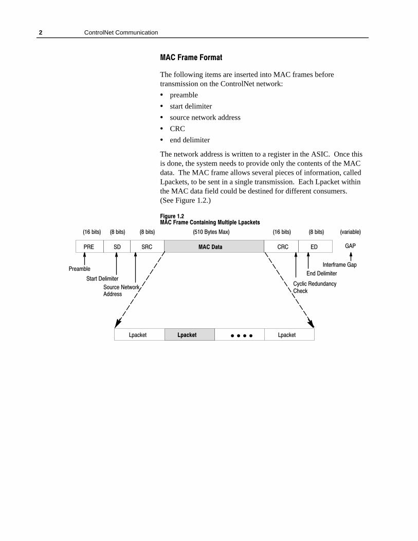
The following items are inserted into MAC frames beforetransmission on the ControlNet network:
• preamble
• start delimiter
• source network address
• CRC
• end delimiter
The network address is written to a register in the ASIC. Once thisis done, the system needs to provide only the contents of the MACdata. The MAC frame allows several pieces of information, calledLpackets, to be sent in a single transmission. Each Lpacket withinthe MAC data field could be destined for different consumers. (See Figure 1.2.)
����� � ������� ���� � ����������� ������ � ���� ��
�� �� ��� ��� ���� ��� �
����� +&�%� ��*� ���� ��&%���� ��&%����� ��&%� ��� ��&%� ��� ��&%�
��
�(�$������
�$�� ���
�&�$&� ���� �&�$
�"'$��� ��&)"$���$�%%
!�� ���� �&�$
���� ��#����& �#����&����
�+��������'!��!�+�����
�!&�$�$� ����#

3ControlNet Communication
�������� �����
As shown in Figure 1.2, the MAC data field can contain severalLpackets, which are the packets of interest to a user’s application.Each Lpacket contains a single piece of application informationdestined for one or more nodes on the network. Packets sent orreceived on the physical wire contain data of interest to theapplication layers as well as a connection ID (CID ), control byte,and length byte. (See Figure 1.3.) An application uses the CID todetermine whether or not a particular Lpacket contains the data itneeds.
������ ����� ������ �����
������ ������� ���������
������
���������������#���
������
������������
The CID is an identifier or name automatically created byControlNet nodes. A CID is a shorthand method for referring to aparticular object message. In the figure above, the CID can be oneof two formats:
• fixed connection ID (2 bytes)
• general connection ID (3 bytes)
A Fixed Connection ID is two bytes long and contains a servicecode and destination network address byte. (See Figure 1.4.) The code byte is used to indicate the service required, while thedestination byte indicates to which network address it is to bedelivered.
������ ��������� ��� �����
������ ������� ������������ ���������
�"���������������
�� �#���
�� �������
� � � ��������������!���� �������
�� ����������� �� ���� � ���� �������� ����������� ��� ����!����� � �� ������ ���������������� ��������!�

4 ControlNet Communication
A General Connection ID is three bytes long and contains a numberused to identify a specific data packet. (See Figure 1.5.) A generalCID must be a unique value on any ControlNet network.
������ �������� �� ���� ��� �
������ ������� ������������� ������ �
�� �����
����� �� ����������� ��
������� � ����
In some ways, a ControlNet connection can be compared to atelephone circuit. When you place a call, the telephone systemselects a path for your call and sets up each switching station in theroute to handle it. As long as the call continues, the resulting virtualcircuit remains open, carrying data or voice traffic. In the telephonesystem, a single call can traverse multiple and different-type links.Through all of this, the connection appears the same to both thecaller and the party called: sound in one end becomes sound in theother.
A connection also provides a path between two end points. Once theconnection manager determines the virtual circuit, the route betweenend points is fixed. (See “Connection Manager,” on page 7.) The end points of connections are applications that need to sharedata. Figure 1.6 illustrates a virtual circuit that traverses one or moreintermediate nodes between the source and destination.
������ ��� The terms source and destination imply that aconnection has been established and currently exists.
������ ��������� �� �������
�����
������ ����
���������������
� ��������
�����������

5ControlNet Communication
���������� �� � ����� �
Every node contains the following:
• Unconnected Message Manager (UCMM)
• Message Router (MR)
• Connection Manager (CM)
• ControlNet Object
• Identity Object (ID)
����������������������
����������������
�� ���������� ��� ���� ��� ������ � ������� ��� �������� ��� ��� ��� ��� �� ����������
�� ���������
����������� ��� �� ��
� ��� ���� ������ �
����������
�� ������ ��� ��
������������ ��� � � ��
� � ����������� ��
��������� ��� �������
In addition, a connection originator node contains a ConnectionScheduler (CS) Object
The following sections about establishing a connection provide:
• a brief functional description on each connection object listedabove
• a graphic as well as written explanation of how these componentsinteract while a connection is initiated and established
Unconnected Message Manager (UCMM)
The UCMM facilitates the exchange of information used to establish,open, or close a connection between applications. In addition, it isused to convey non-repetitive, non-time critical data on a single link.To establish a connection, the Connection Manager provides theUCMM with the network address and path to the target node. Oncethe connection is established, the address and path are no longerrequired. Opening the connection establishes a CID, which will beused to exchange application information.
As shown in Figure 1.7, each message the UCMM receives isforwarded to the Message Router where it is analyzed and sent to itsspecified function or object. The UCMM keeps a transaction recordof each message received so that a reply can be sent to the properlocation. Open and Close connection request messages are alwayssent via the UCMM. In addition, the UCMM provides:
• duplicate detection
• automatic retries
• message time-out

6 ControlNet Communication
������ ��������� ���� �������� ������ ����������
����
���� ��������
����
���� ��������
������ ������
����������������
��������� UCMM messages are always sent in the unscheduledportion of the network interval.
Message Router
The Message Router (MR) allows an application to open connectionsto multiple objects within the same node. It acts much like aninternal switchboard for a node’s objects. Other nodes may establisha connection with the MR through the UCMM and connectionmanager. Figure 1.8 is an example of how the MR functions.
������ ������������ ������ ��������
������ ����
���� ��������
����������
����
�����
�����
�
�
�
�
����������
1. The MR determines which object is to perform the specifiedservice by interpreting the identifying portion of the message.
2. The message is forwarded to the destination object.
3. A response from the destination object for the requesting object isreceived.
4. The MR forwards the response to the requesting object via anestablished connection.
��������� Connections can be created without a MR connection; amessaging connection to the MR is only mandatorywhen the originating application requires access tomultiple internal objects through the same connection.

7ControlNet Communication
Connection Manager
The Connection Manager (CM) allocates internal resourcesnecessary for each connection. Connection requests are originatedby:
• other nodes via the UCMM
• an application on a node
Figure 1.9 is an example of how the the CM of a target nodefunctions upon receiving a connection request by an originatingnode.
������� ���� ����� ����������� ��� ���� ����������� �������
����������������� ���
������������������
����������
��������������������
��
��� ��������
�
�
�
�
�
����������� �������
1. The originator’s UCMM contacts the target’s UCMM with aconnection request.
2. The request is routed through the target’s MR to the CM.
3. The CM allocates the needed resources.
4. A connection is made to the originator node.
The ControlNet network uses the Producer/Consumer model toexchange application information. This model is the basis forunderstanding all ControlNet transactions. The following builds aproducer/consumer model by discussing its basic components:
• object messages
• connection ID (CID)
• producer/consumer connection types
• transport services
• transport connection types
���� ���������������������

8 ControlNet Communication
������ ��� ���
In the ControlNet network’s Producer/Consumer model, objectmessages are used to exchange information. An object message is apiece of information that interests one or more nodes on the network.It carries a value or set of values with a description of the value’smeaning. The ControlNet network transfers object messagesbetween producers and consumers to convey information.
The network view of messages, shown below, is simplified tofacilitate minimal processing, high performance, and smallcode-requirements. It contains only that part of an object’s value thatchanges with time.
���� ������ �� ������ � �
Nodes watch for certain CIDs transmitted by producer nodes. Once a node recognizes a CID, it consumes the message, thereforebecoming a consumer. The network assumes that each objectmessage has exactly one meaning but may have one or moreconsumers.
������������������ ����������� �����
The concept of one producer and one consumer, illustrated in Figure1.10, is known as a point-to-point connection.
������� �������������������� ������������������ ����������
�� ��
�� ��
��������
��������
The concept of more than one consumer per message, or multicast, is shown in Figure 1.11. The dashed arrow represents an objectmessage. In Figure 1.11, Node 1 produces a message on thenetwork. Nodes 4, 7, and 8 consume the message. Nodes 2, 3, 5, and6 see the message but are not interested in it and do not consume thatmessage.
��� ������� ���� ����� � �� � � ������������� ������ � ���� �� � ����� � ��� �� ��� �� � ������
�� ��������� ��� ������������� ��� �
�� ��������� ��� �� � ������ ��� �

9ControlNet Communication
��!��� ������!� ���� � ����!�������!���� ����� ���
������
������
������
������
������
������
������
�����
����!���
���!���
���!���
���!���
����� �� � Nodes can be producers, consumers, or both. Forexample, in Figure 1.12, Node 4 may want to send anobject message to Node 3 based on the information itjust consumed from Node 1.
��!��� ������� ������� ���� ��� �� �� �� ����!���� ���� ���!���
������
����!���
������
������ ������ ���!���
ËËËËËËËËËËËË
���!�������!���
����� �� ������������� ��� ��������
�������� � ���"����
Table 1.A lists the two general-purpose transport classes that havebeen defined for the ControlNet network. Each transport classprovides a different level of service. It is these services that allowcommunication between applications. Transport classes with highernumbers incorporate and build upon the functions of lower transportclasses. The originating application must determine which transportclass best suits its needs for a particular data transfer.
������ ������������ � ������
����� !���� ����� ���
� ����� ��� ���������
� ��������
Transport Class 1 (T1)
Transport class 1 is illustrated in Figure 1.13. Class 1 provides theminimum level of service only, duplicate data detection.

10 ControlNet Communication
������ ������� ������� � ��� �
� ��� �� �� ������� ����
� ����� ���� ����������� ��� ������� ���������� �� ��� � � ��������
� ����� ��� � �� ��� ��������� ������ ��� ������ �������� �� ������ ������
� ���� ���� ��� ��� ������ ���������� ����� �������� ��������� ��� � ���� � ����� �� �������� ����� ����� � ����������� ���� �������� �� ���� ��� �������
� ���
� ��� �������
��������
�
������� ���� �������� ��������
� ������� �������� ����� ���� ���� �������� � ����� ��� ��������
�
�������
��������
Transport Class 3 (T3)
Figure 1.14 illustrates transport classes 3. Class 3 provides dataverification.
������ ������� ������� � ��� �
� ��� �� �� ������� ����
� ����� ���� ����������� ��� ������� ���������� �� ����� �� ����� � ����������� ���� �������� � ���� ���� ���������
�� ��� ����� ������� � � � �� � � � ���� ��������� ��� � ���� ������ ��� ����� � � ���������� �������� � �� �������
���������� ��������� �������
� ���
� ���
ËËËËËËËËËËËË
���������������
ËËËËËËËËËËËËËËËË
���������������
������� ���� �������� ������� ������� ��� �������� ����� ���� ���� �������� �������
�������� � � ������������� ��� ����� � � ��� ����� �� �
� �
�
�
�� ������� ���������� �����
The ControlNet network supports two types of connections:
• point-to-point connections use one producer and only oneconsumer. No additional connections can be added.
• multicast connections allow one producer of data with more thanone consumer.
Both types of connections can be defined further by the application,depending on the particular services that application requires.

11ControlNet Communication
Point-to-Point Class 1
Figure 1.15 illustrates a point-to-point connection betweenapplications. In this example, data is simply sent from oneapplication to another. No services other than data delivery andduplicate detection are provided by class 1. This type of connectionis commonly used for cyclic I/O data transfers (class 1).
������� ������������������ ����������� ������ �� ������� �� ��� �
�
�
�����
�����
������ ���� �� �������������
�������� ������ ������ ������
��������� ����������������� ������ ������� ����
������������ ������
����������� ������� ���� ������� ����� � ����� ���� �������� � ����������� �������� ���� ������� ��������� ���� ��������
�������� ���� �������� ���� �
�
� �������� ��� ������ ���� �
��������
�������

12 ControlNet Communication
Point-to-Point Class 3
Figure 1.16 illustrates a point-to-point connection with deliveryverification. In this type of connection, the application can specify aclass 3 transport. The delivery notification is used for messageverification (class 3). A typical use for this type of connection isclient/server message traffic.
������ ����� ����!��! ����� ���������� ������ ���������� ����� �
������
������
����������� ���������
��������������������ËËËËËËËËËËËË
������� �������
ËËËËËËËËËËËË
������� �������
�����
��� ��
����������� ��� ��� � � �� � ���� � ����� ��� ��������� � ����������� ������ � � �� � �������� ��� � �������
�������� ���� �������� ������� � �������� ���� �������� ����� ����� � �� ������� ������� �
�
�
���������� Delivery verification is not a point-to-point connectionrequirement, only an available augmentation.
�� ������ � ��� �������������� � ��������� �������� ���� ������������� ����� �����������������
�� ��� ��� ��� �������������� � ��������� ��� ��������� �������� ������ � ������ ������ ��� �����������������

13ControlNet Communication
Multicast Class 1
Figure 1.17 illustrates a multicast connection that can be definedfurther as class 1 by the application. This example is similar toFigure 1.15. The application may specifies that duplication detectionis required. A common use for this type of multicast connectioncould be an adapter sending inputs to multiple scanners.
������ �������������� ����������� ������ ��������� ������ �
�
������ ������
������
�������� ������������������� ��������
����������� ��������
����������� ��������
��������
�� ����� �� ���� � ��� ������ �� �� � ������ ���� �������� � �� ����� �� �������� ��� ������ �� ������� ���� ��������
�������� ���� �������� ���� �
�
�
�
� �������� ��� ������ ���� �

14 ControlNet Communication
Notes:

�������� ��� ��� �����
This chapter describes the method by which the ControlNet network:
• provides determinism for control and I/O data
• facilitates unscheduled messaging
• allocates resources
• allows access to the network’s media
This chapter contains these sections:
���#��� ����
���� ������ ���!!� ��"��� �
�����#���� �� $��� �
��!����#���� �� $��� �
�#� ����� �
Access to the network is determined by time. Each node maytransmit only during its assigned turn, which falls within a specifiedtime frame. An algorithm called Concurrent Time DomainMultiple Access (CTDMA ) regulates the opportunity to transmit.This opportunity repeats itself at precise intervals. The NetworkUpdate Time (NUT) is the fixed and known rate at which thisnetwork update interval (NUI) is repeated. Figure 1.1 illustrates therepeating NUI in which nodes can transmit their scheduled andunscheduled messages. As depicted below, the NUI is divided intothree sections:
• Scheduled
• Unscheduled
• Guardband (network maintenance)
��$!�� �������� ���#!����#� ��#&�!��"� ����� ����""� �#���
ÇÇÇÇÇÇÇÇÇÇÇÇÉÉÉÉ
ÉÉÉÉÄÄÄÄ
ÇÇÇÇÇÇÇÇÇÇÉÉÉÉÉÉ
ÉÉÉÉÉÉÄÄ
ÇÇÇÇÇÇÇÇÇÇÇÇÇÇÇÇÉÉÉ
ÉÉÉÄÄÄÄ
���!� "���� �!� �!� $��� �� �"����$��� � ��!!���� " �����
���!� "����� ������� "��&�$�!�������� � �!� �!� $��� ��
��#&�!�� ����#������
����
���!� "���� �!� �!� $��� �� $�"����$��� � ��!!���� " �����
��#&�!�� � ��#�� ��#�!%��
���� ����� ����""� �#���
����$!!��#� ����� ������ $�#� ��� ����""� ��� ���!� "��� ���� �"��� %�"�� %����"��� ��" �� �"� ��"%� �" ��!��"!� ��"��
���� ��#&�!�� � ��#�� ��������� � �!� "��� ���"�"�$�� "�����"� $��� ��� %����� ��"�� ������ !��"� ��� "��� ��" �� �"��"%� ��
2 ControlNet Network Protocol
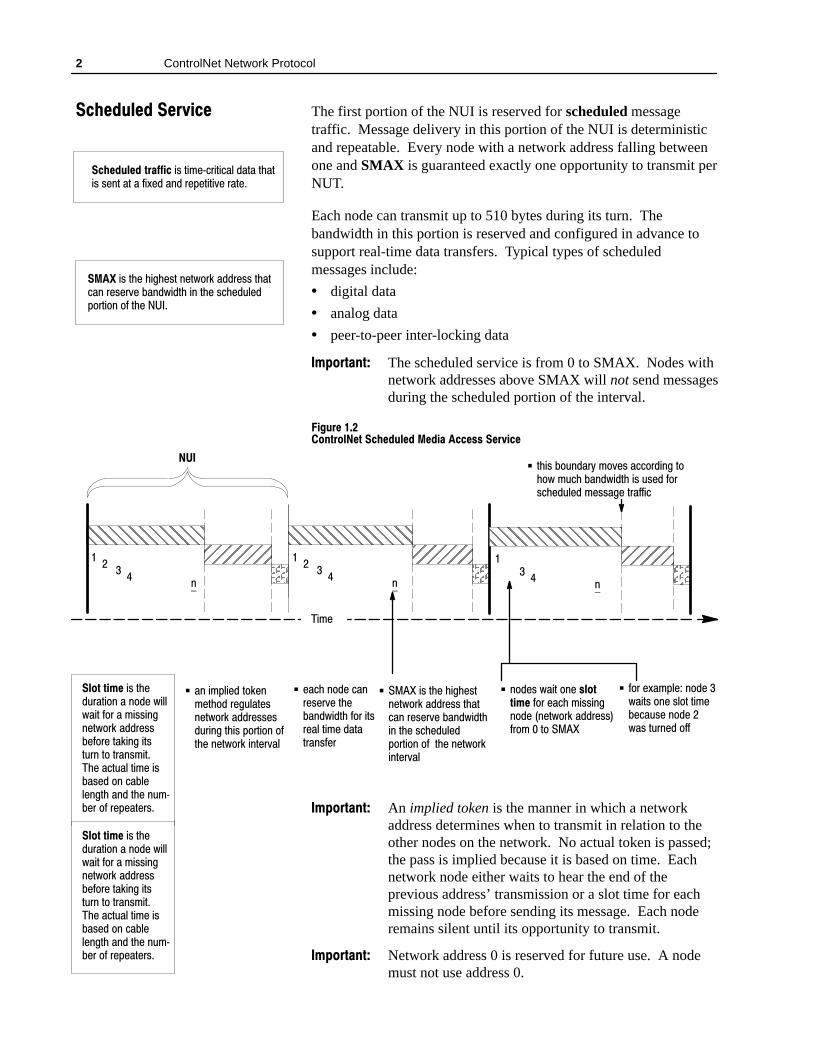
The first portion of the NUI is reserved for scheduled messagetraffic. Message delivery in this portion of the NUI is deterministicand repeatable. Every node with a network address falling betweenone and SMAX is guaranteed exactly one opportunity to transmit perNUT.
Each node can transmit up to 510 bytes during its turn. Thebandwidth in this portion is reserved and configured in advance tosupport real-time data transfers. Typical types of scheduledmessages include:
• digital data
• analog data
• peer-to-peer inter-locking data
��������� The scheduled service is from 0 to SMAX. Nodes withnetwork addresses above SMAX will not send messagesduring the scheduled portion of the interval.
������� ��������������� ���������� ����� ������� ��� ���
ÇÇÇÇÇÇÇÇÇÇÇÇÇÇÉÉÉÉ
ÉÉÉÉÄÄÄÄ
����
��
�
�
ÇÇÇÇÇÇÇÇÇÇÇÇÇÇÉÉÉÉ
ÉÉÉÉÄÄ
��
�
�
ÇÇÇÇÇÇÇÇÇÇÇÇÇÇÇÇÉÉÉ
ÉÉÉÄÄÄÄ
��
�
� ����� � ��� ����"�#�"&�� $�������'��$�� � "� �$#�"���� $���� ��$��$"��#��"
�
� � ��� �#� $��� �����#$���$' "�� ���"�##� $��$����� "�#�"&�� ����'��$����� $��� #����%����! "$� �� �� � $��� ��$' "����$�"&��
� � ��#� '��$� ��� ���������� � "� ����� ��##����� ��� ���$' "�� ���"�##��" �� �� $ � � ��
� $��#� � %���")� � &�#� ��� "����� $ �� '� �%��� ����'��$�� �#� %#��� � "�#����%���� ��##���� $"�����
� � "� �(��!��� � ��� ��'��$#� ��� #� $� $��������%#�� � ��� ��'�#� $%"���� ��
� �� � ��!����� $ ������$� �� "��%��$�#���$' "�� ���"�##�#��%"���� $��#� ! "$� �� ��$��� ��$' "�� ��$�"&��
��������� An implied token is the manner in which a networkaddress determines when to transmit in relation to theother nodes on the network. No actual token is passed;the pass is implied because it is based on time. Eachnetwork node either waits to hear the end of theprevious address’ transmission or a slot time for eachmissing node before sending its message. Each noderemains silent until its opportunity to transmit.
��������� Network address 0 is reserved for future use. A nodemust not use address 0.
���������� ��� ���
���������� �������� �#� $���*�"�$����� ��$�� $��$�#� #��$� �$� �� ��(��� ���� "�!�$�$�&�� "�$��
���� �#� $��� �����#$� ��$' "�� ���"�##� $��$���� "�#�"&�� ����'��$�� ��� $��� #����%���! "$� �� �� $��� ����
����� ����� �#� $���%"�$� �� �� � ��� '���'��$� � "� �� ��##�����$' "�� ���"�##��� "�� $������ �$#$%"�� $ � $"��#��$����� ��$%��� $���� �#��#��� �� ���������$�� ���� $��� �%�*��"� �� "�!��$�"#�
����� ����� �#� $���%"�$� �� �� � ��� '���'��$� � "� �� ��##�����$' "�� ���"�##��� "�� $������ �$#$%"�� $ � $"��#��$����� ��$%��� $���� �#��#��� �� ���������$�� ���� $��� �%�*��"� �� "�!��$�"#�

3ControlNet Network Protocol
The unscheduled portion of the NUI begins after all schedulednodes have had an opportunity to transmit. The time remainingbefore the beginning of the guardband is available on a sequentiallyrotating basis to all nodes, with a network address between 0 andUMAX . This rotation continues until the beginning of theguardband. The right to transmit first in the unscheduled portionrotates one node per NUI.
��������� A node may have the opportunity to transmit manytimes during the unscheduled portion of the NUI;however, a node is not guaranteed an opportunity everyNUI.
In Figure 1.3, node 7 begins the unscheduled portion in theexample’s first NUI. Node 8 transmits first in the second NUIregardless of who finished the last interval. Typical types ofunscheduled data include:
• connection establishment
• peer-to-peer messaging data
• programming data (uploads and downloads)
���������
• the unscheduled service is from 0 to the value of UMAX . Inaddition, UMAX is always greater than or equal to SMAX
• nodes with addresses greater than SMAX and less than or equalto UMAX may only send unscheduled messages
• nodes with a network address less than or equal to SMAX maysend both scheduled and unscheduled messages
• nodes with network addresses above UMAX may notcommunicate on the ControlNet network
�� ��� ��������������� ������� ���� ������ ������� ��!���
ÇÇÇÇÇÇÇÇÇÇÇÇÇÇÉÉÉÉ
ÉÉÉÉÄÄÄÄ
����
ÇÇÇÇÇÇÇÇÇÇÇÇÇÇÇÇÉÉÉÉ
ÉÉÉÉÄÄ
ÇÇÇÇÇÇÇÇÇÇÇÇÇÇÉÉÉÉÉ
ÉÉÉÉÉÄÄ
��
��
� �
����
���
�
��
� !��$� (��%� ! �� $�!%�%���� �!#� ����� ��$$� �� !��� � �%(!#�� ���#�$$���#!�� �� %!� ����
����
� ����� !��� ��)�%#� $��%� �� )� %���$�!#� !%� �%� ���
� & $����&���� ����'�#)� �$� !%� ��%�#�� �$%��� !#�#�"��%����
� � � ��"����� %!�� � ��%�!��#��&��%�$� �%(!#�� ���#�$$�$��&#� �� %��$� "!#%�! � !�� %��� �%(!#�� � %�#'��
������ !""!#%& �%)� %!� %#� $��%� ��#$%� � � %��� & $����&���"!#%�! � !�� %��� �� � "�$$�$� ! � �� #!%�%� �� ��$�$�
������� ���� ��!���
����� �$� %��� �����$%� �%(!#�� ���#�$$� %��%� �� �!��& ���%�� �&#� �� %��� & $����&���� "!#%�! !�� %��� �� �� � ���� ����&�%� �$� ����� �� �
������� ���� �������� �$� ��%�� (����� ��$� !%���*�#�%����� �! $%#�� %$�

4 ControlNet Network Protocol
The Guardband is the final part of the NUI and is reserved fornetwork maintenance. During this time, the moderator transmitsinformation, called the moderator frame, which keeps all nodessynchronized (Figure 1.4).
��������� As the application dictates, the user can perform anetwork change algorithm to edit configurationinformation within a moderator frame. This changemay or may not force a change in the NUT.
������� �������� ��������� ������ ������������ ������� �� � ���������
��������� �����
� ��
� ���� ��� ����
� ���� ����� � ���� �����!��� �� ��� ���� ��"�� ��� �������� ����
ÇÇÇÇÇÇÇÇÇÇÇÇÇÇÉÉÉÉ
ÉÉÉÉÄÄÄÄ
���
ÇÇÇÇÇÇÇÇÇÇÇÇÇÇÉÉÉÉ
ÉÉÉÉÄÄ
ÇÇÇÇÇÇÇÇÇÇÇÇÇÇÇÇÉÉÉ
ÉÉÉÄÄÄÄ��������� ��������� ���������
�
��������� Each node’s ASIC has the ability to act as a moderator.If the current moderator node ceases to operate, thenode with the next higher address assumes themoderator duties.
����������
��� ���������� ��� ���� ����� ���� ���� �� ������ ���� �������� � ������� ���� �� ��� ���� ��������� �� ������� ���� ���������� ������

� ���� � �������
This chapter contains these sections:
������� ���
���� ����� ��� �
�!�#����� �$��#���" �
���$����#���� �!���""�! �
$��( �!#� ��� �
����� ���#&�!�� �� ����#" �
���$����#���� �'�� ��� ��� �
ControlNet media-access control-hardware (ASICs) are interfacechips that allow a product to access a ControlNet network. The ControlNet ASIC is called CNA10. The CNA10, in conjunctionwith class-specific Firmware, provides connection layer services, as shown in Figure 1.1.
������ ��������������� ������ ���� ���� ����������� ��"��� �� �������� �� ����
��#!����#�!��"���%�!
��#!����#���$����#���
���#&�!�
��#!����#�����""� ��#!�� �!�&�!�
������������
���!���
���������
�����
��"��
��"��
��"��
��"����������"������
The CNA10 ASIC is an interface chip for Intel� and Motorola�host processors. It provides the following features:
• a 16-bit communication processor
• a 3K byte dual-port RAM interface
• hardware support for 31 connected channels
• a data quarantine service
• transport services
���� ������ ���

2 ControlNet Enablers
The protocol machine within the CNA10:
• contains media access controller
• receives data from the host processor and network
• transmits data via its modem and a transceiver onto the network
• filters data received from the network
• holds data to be transmitted or received in buffers within theASIC
• supports optional redundant media
• contains ControlNet Object Powerup and State Transition Logic.
The CNA10, Allen-Bradley’s ControlNet ASIC, supports allrequired media access functions. In addition, through a dedicatedon-chip communication processor, the CNA10 ASIC supports muchof the required transport protocol, shown in Figure 1.2. This facilitates a simple dual-port RAM interface to a user-suppliedhost-processor, shown in Figure 1.3

3ControlNet Enablers
��'$�� �������� �"!&$"���&� �" '!���&�"!� "���� �!�� &��� �������$(���%
ÇÇÇÇÇÇ
ËËËË
ÊÊÊÊ
�%�$� �$!(�����!�&)�$�
�! &$!���&�!��' ���&�! *��"��� �!��
������ �����$�)�$�
�! &$!���&�$� %���(�$�!�"! � &%
�! &$!���&� �����!�"! � &%
ËËËËËËËËËËËËËË ����� ����%%� ��$(���%
ËËËËËËËËËËËËËËËËËËËËË
ÊÊÊÊÊÊÊÊÊÊÊÊÊÊÊÊÊÊÊÊÊ
��!�� ��*�$� $�(�$
��*%����� ��*�$� �!&�$����
�##����&�"!�
��&)"$�
�$�!%#"$& ��*�$
��*�$
��*�$
��*�$��!�
����� ����%%
����� � � ����+%������+�$
ËËËËËËËËËËËËËËË
� �! ��&�! � � � � � �����%
ÇÇÇÇÇÇÇÇÇÇÇÇÇÇÇÇÇÇÇÇÇÇÇÇÇÇÇÇÇÇÇÇÇÇÇ
ÇÇÇÇÇÇÇÇÇÇÇÇÇÇÇÇÇÇÇÇÇÇÇÇÇÇÇÇÇÇÇÇÇÇÇÇÇÇÇÇ
� �! ��&��� � � �%%���� � � � ���$� � � ��� �
�! &$!�� � ����� ��&�
� ��&�&$����$
ÇÇÇÇÇÇÇÇÇÇÇÇÇÇÇ
�%%����� �!'&�$
�! ��&� $�#'�%&� � ���%%���� ��&�
�%�$�%� �##����&�"!� �����&%
ËËËËËËËËËËËËËËËËËËËË
�$� %"!$&� ��$(���%
ÇÇÇÇÇÇÇÇÇÇÇÇÇÇÇÇÇÇ
�! ��&�! � � ���$
As shown in Figure 1.2, the communication example code runs in ahost-processor and is responsible for supporting all layers below it.It is application-specific example code and is offered byAllen-Bradley to assist designers in creating their own productsoftware. Because every product has slightly different applicationrequirements and may require a different host-processor, it is notpractical to supply a single software package to fit all needs.Therefore, Allen-Bradley has developed several examples of how aspecific application could be applied using the CNA10. Theseexamples can be used as a foundation for a CNA10-based product.

4 ControlNet Enablers
���%"�� ������ ��� ���"��� ���'� �� $��� ����
�!& %�#$
�����
�!��& ���%�! � �
�!��& ���%�! �#!��$$!#
&����!#%���� !$%
����� $�����%!#
�! ���&#�%�! ��%$
�%�%&$��
�$�#�""����%�! �" $ � �
�%��$� �#
���!" ��## "� ���"����&��$"��#��$�����# !����$�#�"����"
���
�#� $���'�#
����
�
The CNA10 ASIC protocol engine supports the following features:
• MAC processor
• modem services
• transmit and receive FIFOs
• Lpacket screeners
• cable redundancy
• NAP
• signal integrity checking (CRC)
The CNA10 modem sends and receives data in the form of MACframes. Its protocol controller constantly tracks which node is nextto transmit and manages the receive and transmit process. When apacket is waiting to be sent, it is held in transmit FIFOs until its turn.Before a received Lpacket can be processed, it is screened by theLpacket screener. The Lpacket’s CID is read and compared to aninternal, host-programmed list of CIDs. If a match is found, thescreener attaches an index value to the Lpacket and sends it to thecommunication processor.
�" $ � �� �%��$� �#
�����
���%��$� �#
�#� $���'�#
���
�� �$� � � ��#! (��!#� (�������& �� �(� �����
�� �$� � � ��#! (��!#� ! ��%�! �� %����#�

5ControlNet Enablers
The communication processor is a 16-bit micro-processorresponsible for the implementation of communication transportfunctions. It quarantines packets from the receive FIFO until theirCRC can be verified. The communication processor also sends andreceives data from the dual-port RAM. To the host, the CNA10simply appears to be RAM.
�#!!("���'�#"�%#��&&#%
�(� ��#%'��� �#&'
�#!!("���'�#"���
The CNA10 provides one transmit and one receive ring buffer thatsupports an Unconnected Message Manager (UCMM) transport aswell as 31 connected channels. In general, ring buffers are used forunconnected messaging such as open/close requests and client/servermessaging, while the connected transport channels are used forreal-time I/O data transfers.
For more information, refer to the pages listed in the table below.
���� ������������ ������ ���
��� %�!�&� �"�� �$����'& �#"'%# ��'� �#!!("���'�#"�� $���� �
����� �"�� ��� �#"'%# ��'� ��')#%�� �%#'#�# �� $���� �
�#""��'�#"� ��& �#"'%# ��'� �#!!("���'�#"�� $���� �
The dual-port RAM is the point at which the host processorphysically and logically connects to the CNA10. It is 3K-bytes insize and provides buffers for:
• configuration
• interrupt control
• communication services
• one receive and one transmit ring buffers (UCMM and T3)
• each of the 31 connecting channels (two channels required foreach T1 connection and one channel required for each T3connection with its data routed through the ring buffers)
�#!!("���'�#"�%#��&&#%
�(� ��#%'��� �#&'
�������������� ���������
�
����"����� ��
��������
�����
�������
� ���
�������������
�!� ����� ������
�!� ����� ������
����������� ��������
����� ����� ��
�����*'�&
�����*'�&

6 ControlNet Enablers
��! "$��$� The sum of all areas must not exceed 3K-bytes. In addition, the boundary between the ring buffer andconnection buffers is fixed at the time of configuration.
These features facilitate transport support inside the CNA10.
������ ���� ����$��� ���� ��� ����$��� %���"� ��(�#
%���" ����%� �'��%� ����%�$
��� ������"��� �������! �� %� �!� �� � ������� ��� %� �! ��"� ����������
�� � �& ��� %� �! ��� ��� %� �!
�� � �& �� %� � ��� ��� %� �!
CNA10 software components are located both in the ASIC firmwareand in the host processor. These components operate together toprovide services to applications. The following description builds ageneral profile of its capabilities by explaining each of its majorsoftware components and processes.
��� ����$��� �##���� �����"� �� �
Unconnected Message Manager delivers and buffers messagesbetween nodes that do not have an available and establishedconnection between them. The messages may be a request to open aconnection or simply non-repetitive, non-time critical data. AllControlNet nodes are required to have UCMM message transmit andreceive capability. For this purpose, the CNA10 provides transmitand receive services on an independent channel across a single link.UCMM messages may be serviced anytime the ASIC is online.They do not require prior setup or negotiation by the client andserver. The UCMM service is primarily used for:
• establishing real-time data transfers
• non-connection event information between nodes
Because it is not necessary to establish a connection for UCMMmessages, they may be sent at any time. If a response timeoutoccurs, the application is responsible for any retries.
��! "$��$� These messages have no guarantee of delivery. Also, acommunication failure will result in a response timeout.
����� � �$&�"� �! ���$#
������� ����!� "�� ����"�$��'� �� "�����"������ "������#����"�����"%� ��
��#���#� ��� $��� #$� !" ��## "

7ControlNet Enablers
������� ������� ���
The Message Router routes all incoming messages to the appropriateobjects. Valid destinations are any internal object class as well asany application object-class that has been registered with the MR.All received UCMM messages are forwarded to the MR for deliverywithin the node.
���������
All message transfers use a specific transport class. Unconnectedmessages have one class called UCMM transport while theconnected messages have two, transport classes 1 and 3. The tablebelow indicates which transport classes are supported by the CNA10.The bulleted items are CNA10 supported transport functions.
• allocation/de-allocation
• start/stop
• write
• trigger
������ ����� ������ ��� ����� ���������� �
� ��� ����� ������ ��
� ����� ��
����������� ������� ���
The Connection Manager is responsible for establishing andremoving connections supported by the CNA10 ASIC. Also, as theCM determines the allocation of resources, it must determine if aparticular connection request can be honored by its node. The availability of connection channels and bandwidth allocationdirectly impacts the acceptance or rejection of a connection request.
�������� ��� �������� ���������
�������� ��� �������� ���������

8 ControlNet Enablers
Time Critical Bandwidth Allocation in the Connection Manager
Upon start up, part of the configuration data received specifies howmuch time-critical bandwidth on the network has been allocated tothe node; it is allocated strictly on a first-come, first-serve basis.Depending on the sophistication of the application, the CM can bedesigned for one of three levels of connection request versusbandwidth reviewing:
• low-end: Connections supported by the node are fixed. The CMcan only accept a request that exactly matches one of theavailable connections.
• mid-range: The CM compares connection requests to a variablelength list of acceptable connections. The product application hasthe option to modify the list when desired.
• high-end: The CM will attempt to optimize the allocation ofControlNet bandwidth. It minimizes stale data by generating aconnected-data transmit-schedule with uniform loading over timeat the requested throughput.
��������� Connections can only be established to either theproduct application objects or to the MR object.
The communication example code, shown in Figure 1.2, supports aset of application objects and interfaces. This set of objects andinterfaces may differ, depending on the type of product beingdeveloped. Communication software examples have been developedwith the appropriate objects and interfaces to support the real-timeI/O class and the non-time-critical messaging class. Examples ofhow products would exchange data with the other classes is shown inFigure 1.4
������ ��������������� ������� �������
���
�������
�������� ������ ������
���������� ������ ������ �������� ������ ������
���
�������
���
�������
�������������� �����������

9ControlNet Enablers
��������� ����
Messaging Class products support only unscheduled messages to allproduct classes; all other product classes also support unscheduledmessage traffic. A Messaging Class product is an initiator orresponder to connections (T3) and exchanges unconnectedclient/server messages (UCMM). It is only used in non-time criticalapplications because response time in the ControlNet unscheduledservice is not deterministic. Typical Messaging Class productsinclude:
• monitoring devices
• software-based supervisory products
• operator interface devices
• programming tools
• PCMCIA interface cards
• other computer interface cards
• calibration tools
������ � ����
An Adapter Class product emulates functions provided by traditionalrack-adapter products. This type of node exchanges scheduledreal-time I/O data with a Scanner Class product (example, a PLCscanner); it does not initiate connections on its own. However, it cansupport unconnected messages as a server. This facilitates theAdapter Class product’s ability to exchange real-time I/O data with aPLC processor as well as unscheduled messages to exchange devicecalibration, status, and configuration information with a MessageClass, Scanner Class, or other Adapter Class node. Typical AdapterClass products may include:
• rack adapters
• drives
• weigh scale
• operator interface devices
• welders
• robots
����� � ������ ������ �������� ������ �� ���������

10 ControlNet Enablers
������� ���
A Scanner Class product exchanges scheduled real-time I/O datawith Adapter Class and Scanner Class products. This type of nodecan respond to connection requests and can also initiate connectionson its own. In addition, the Scanner Class supports unconnectedmessages as a client or server. This facilitates emulation of a PLCprocessor in all respects. It can exchange data with other products inits class as well as directly to racks of I/O cards. Typical ScannerClass products may include:
• PLC processors
• I/O scanners
• drives
• motion controllers
• robots
• CNCs