? ? ? ? ? ?. 3 point bending test : varying loads and spans variables measured in the gravity...
TRANSCRIPT

Recent Works on PETALto Validate FE Model
??????

MECHANICAL TESTS
3 POINT BENDING TEST: Varying loads and spans Variables measured in the gravity
center:Deflections with vision machineStrains with gauges in longitudinal
and transverse directions Estimated Parameters:
Efacings
Gcore 4U
PL
48D
PLδ
3
)1(12
)( 33
f
f
v
cdbED
c
cdbGU c 4
2
10000 110000 210000 3100000
0.01
0.02
0.03
0.04
0.05
0.06
f(x) = 0.0000001583035 x + 0.012979185R² = 0.968462173594817
δ/P5L
L2(mm2)
δ/P
5L

MECHANICAL TESTS
VIBRATION TEST WITH CONSTRAINTS and FREE BOUNDARY CONDITIONS: Test Positions: Suspended and Restricted Applied Loads: Impulse and Harmonic Loads Variables measured in different points along the petal:
Accelerations and forces Estimated parameters:
Mode shapes and its Natural frequencies.
0 200 400 600 800 1000 12000
50
100
150
200
250
Suspended
Restricted

STEADY STATE THERMAL TESTS (David)
Tª Box Air (ºC) Coolant
Tª Pipes_Coolant
(ºC)
Surface Strains (µm)
T ª Surface Petal (ºC)
12 H2O 12 No Yes
12.5 H2O 27.5 No Yes
10 -- -- Yes No
10.7 CO2 -27 Yes Yes
11.1 Chiller _FRICOFIN -25 Yes Yes
THERMAL TEST CONDITIONS AND MEASUREMENTS : Variables measured along the petal:
Transverse Strains with capacity sensorsSuperficial Temperatures with IR camera and PT100s.
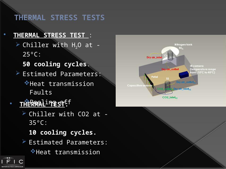
THERMAL STRESS TESTS
THERMAL STRESS TEST : Chiller with H2O at -25ºC:
50 cooling cycles. Estimated Parameters:
Heat transmission FaultsPeeling off
THERMAL TEST: Chiller with CO2 at -35ºC:
10 cooling cycles. Estimated Parameters:
Heat transmission
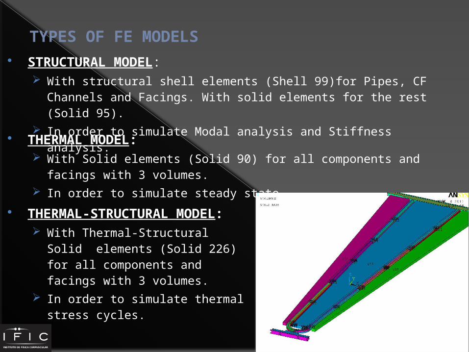
TYPES OF FE MODELS STRUCTURAL MODEL:
With structural shell elements (Shell 99)for Pipes, CF Channels and Facings. With solid elements for the rest (Solid 95).
In order to simulate Modal analysis and Stiffness analysis.
THERMAL MODEL: With Solid elements (Solid 90) for all components and facings with
3 volumes. In order to simulate steady state.
THERMAL-STRUCTURAL MODEL: With Thermal-Structural Solid
elements (Solid 226) for all components and facings with 3 volumes.
In order to simulate thermal stress cycles.

FEA ANALYSIS VALIDATION AND VERIFICATION OF THE MODEL:
4 Validity checks:Unit Enforced Displacement and RotationFree-Free Dynamics with a Stiffness Equilibrium CheckUnit Gravity LoadingUnit Temperature Increase
VALIDATION WITH EXPERIMENTAL DATA: Dynamic Test:
Free Vibration Modal AnalysisRestricted Petal Modal Analysis with Impulse Load appliedRestricted Petal Modal Analysis with frequencies sweep.
Stiffness Test Steady State Thermal Test Thermal Stress Test
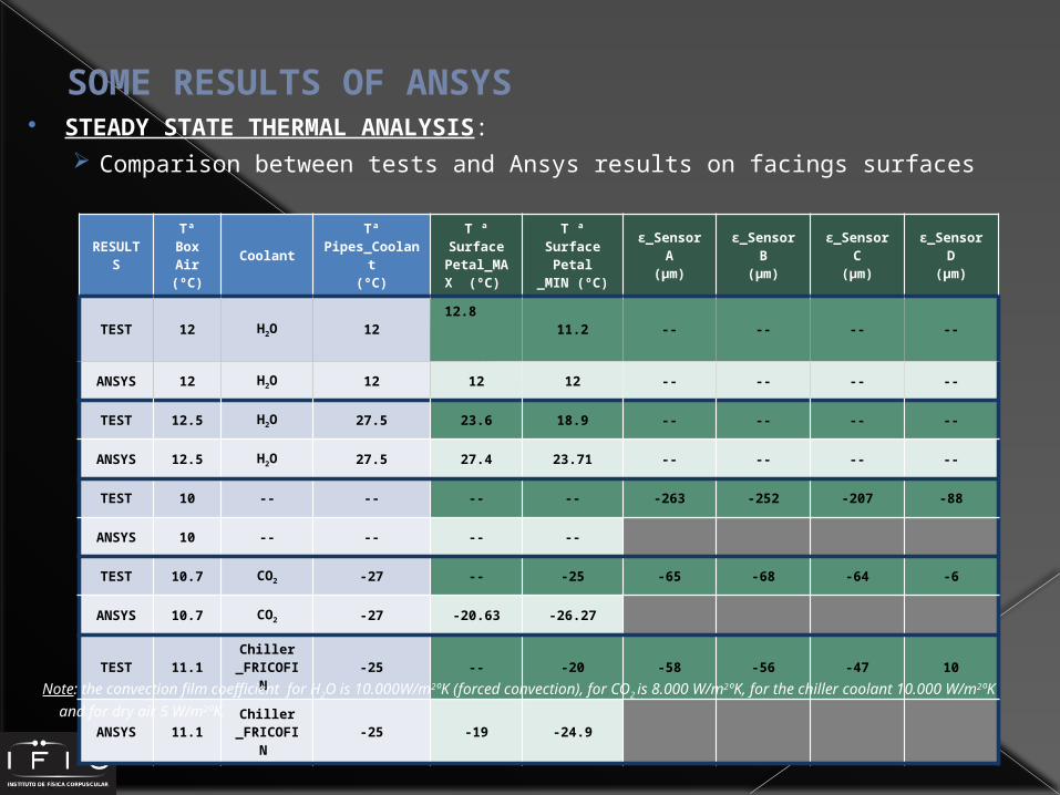
SOME RESULTS OF ANSYS STEADY STATE THERMAL ANALYSIS:
Comparison between tests and Ansys results on facings surfaces
RESULTS
Tª Box Air (ºC)
Coolant
Tª Pipes_Coola
nt(ºC)
T ª Surface
Petal_MAX (ºC)
T ª Surface Petal
_MIN (ºC)
ε_Sensor A
(µm)
ε_Sensor B
(µm)
ε_Sensor C
(µm)
ε_Sensor D
(µm)
TEST 12 H2O 1212.8
11.2 -- -- -- --
ANSYS 12 H2O 12 12 12 -- -- -- --
TEST 12.5 H2O 27.5 23.6 18.9 -- -- -- --
ANSYS 12.5 H2O 27.5 27.4 23.71 -- -- -- --
TEST 10 -- -- -- -- -263 -252 -207 -88
ANSYS 10 -- -- -- --
TEST 10.7 CO2 -27 -- -25 -65 -68 -64 -6
ANSYS 10.7 CO2 -27 -20.63 -26.27
TEST 11.1Chiller
_FRICOFIN
-25 -- -20 -58 -56 -47 10
ANSYS 11.1Chiller
_FRICOFIN
-25 -19 -24.9Note: the convection film coefficient for H2O is 10.000W/m2ºK (forced convection), for CO2 is 8.000 W/m2ºK, for the chiller coolant 10.000 W/m2ºK and for dry air 5 W/m2ºK.

SOME RESULTS OF ANSYS STEADY STATE THERMAL ANALYSIS:
CO2 -27ºCDRY AIR 10.7ºC
Chiller -25ºCDRY AIR 11.1ºC
H2O 27.5ºCDRY AIR 12.5ºC
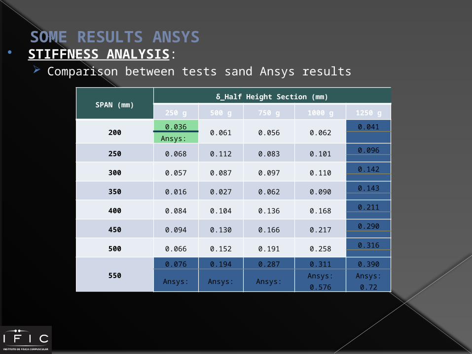
SOME RESULTS ANSYS STIFFNESS ANALYSIS:
Comparison between tests sand Ansys results
SPAN (mm)δ_Half Height Section (mm)
250 g 500 g 750 g 1000 g 1250 g
200 0.036 0.061 0.056 0.062 0.041Ansys:
250 0.068 0.112 0.083 0.101 0.096
300 0.057 0.087 0.097 0.110 0.142
350 0.016 0.027 0.062 0.090 0.143
400 0.084 0.104 0.136 0.168 0.211
450 0.094 0.130 0.166 0.217 0.290
500 0.066 0.152 0.191 0.258 0.316
550 0.076 0.194 0.287 0.311 0.390Ansys: Ansys: Ansys: Ansys: 0.576 Ansys: 0.72

SOME RESULTS OF ANSYS STIFFNESS ANALYSIS:
Analysis with SPAN 550 mm and LOAD 1250 gr
DEFLECTIONS VON MISSES STRESSES

SOME RESULTS OF ANSYS MODAL ANALYSIS:
Free Boundary conditions
MODE
Frequency (Hz)
1 0.12949e-01
2 0.16566e-01
3 0.23572e-01
4 7.50073
5 7.6362
6 21.366
7 22.407
8 26.313
FIRST SIX MODES=
MOVEMENT OF RIGID SOLID
MIN